Embed Size (px)
Citation preview

1 | Industrial Refrigeration – Carsten Dahlgaard
2nd EDITION REFRIGERATION CONFERENCE 2018
Bahrain 25. April 2018
Carsten Dahlgaard
Danfoss

2 | Industrial Refrigeration – Carsten Dahlgaard
Carsten Dahlgaard Danfoss A/S. Denmark
• Main areas of work:
• Senior Director Sales
Europe, Middle East and Africa
• Education:
• Masters degree (Marine Engineering)
• Primary Education Engineering Materials
• Work experience:
• 18 years in Danfoss out of 27 years within Refrigeration
• Branch Manager for IR Contractor
• Senior Director Sales Asia
• Global Marketing Director
• Sale Manager for Industrial Refrigeration (IR) and Original Equipment Manufacturers (OEM)
• Sales Engineer
• Technical Service Support
• Installation Manager for Refrigeration Contractor
• Marine Engineer

3 | Industrial Refrigeration – Carsten Dahlgaard
Danfoss engineers technologies that enable the world of tomorrow to do more with less. We meet the growing need for infrastructure, food supply, energy efficiency and climate-friendly solutions

4 | Industrial Refrigeration – Carsten Dahlgaard
26,645 Employees
WORLDWIDE SALES in more than 100 countries
72 FACTORIES in more than 20 countries
Sales 2017 7 bn USD All 4 segments
Key facts
USA, CHINA
AND GERMANY Top three markets
PRIVATELY HELD Ownership
NORDBORG, DENMARK Headquarters
Danfoss A/S

5 | Industrial Refrigeration – Carsten Dahlgaard
#2 Market position
Business segments
32% of Group net sales
• 6,815 employees • 22 factories in 11 countries • 2.3bn USD
#1 Market position
• 6,396 employees • 13 factories in 10 countries • 1.9bn USD
#2 Market position
24% of Group net sales
• 4,652 employees • 11 factories in 7 countries • 1.7bn USD
#1 Market position
• 5,339 employees • 26 factories in 12 countries • 1.2bn USD
27% of Group net sales
17% of Group net sales
DANFOSS
POWER SOLUTIONS
DANFOSS
COOLING
DANFOSS
DRIVES
DANFOSS
HEATING

6 | Industrial Refrigeration – Carsten Dahlgaard
Industrial Refrigeration
FROZEN FOOD DAIRY PROCESSING MARINE MEAT PROCESSING COLD STORAGE
BREWERIES CHEMICAL PROCESSING
INDUSTRIAL HEATPUMPS
ICE RINKS SOIL FREEZING

7 | Industrial Refrigeration – Carsten Dahlgaard
Innovation highlights 2004-2018
ICV 20 to 65
2004 2006 2011
AKS 4100 ICF 20-25
2012 2014
SVL Flexline SVL SS Flexline ICLX 32 to 150 ICF 15
2016
ICF 50 and 65
2013
EKE 347
ICF SS 20 and 25 ICF Defrost
Module
2017
New Pilots
2018
ICSH 26 to 65 Next Generation GD
SW Heat Exchanger

8 | Industrial Refrigeration – Carsten Dahlgaard
The Formula for Efficiency Danfoss ICFD Defrost Module

9 | Industrial Refrigeration – Carsten Dahlgaard
Small Medium Large
ICF 20
ICF 25
ICF 65 ICF 50
ICF 15 ICF 25
SS ICF 20
SS Liquid Line
Hot Gas
Suction
Defrost Drain
ICFD 20
ICFD 20
ICF 15-4
ICF 20-4
ICF 20-6
ICF 25-4
ICF 25-6
ICF 50-4 ICF 65-3
ICF 20-4
ICF 15-4
Focus is to continually develop our offering to meet customer and market needs and continue the journey from conventional valves and
transfer to ICF valve stations.
The ICF Portfolio
Stainless Steel
Stainless Steel
New function on ICF

10 | Industrial Refrigeration – Carsten Dahlgaard
New opportunities
SVA-FIA-ICS-NRVA-REG-SVA ICF

11 | Industrial Refrigeration – Carsten Dahlgaard
Hot gas defrost by pressure control
Air cooler without the ICF Valve Station
A conventional system with numerous individual valves:
• Installation requires disassembly and re-assembly prior to welding
• Increased risks for leakages due to several weldings
• Complex insulation
• Occupies much space
• Need for regular maintenance on
individual products
FIA
SVA SVA
SVA
ICM
SVA
SVA
FIASVA
REGSVA ICS 1
BSV
CHV
EVM-NCCVP-HP
ICLX ”Wet” return line
Liquid line (pump)
Hot gas line
ICS 3
SNV
SNV
CHV
ICEDRAW.DK
NC NO
SNV

12 | Industrial Refrigeration – Carsten Dahlgaard
Hot gas defrost by liquid drain
Air cooler with the ICF Valve Station
ICF Valve Stations across the wet suction, liquid, hot gas, and defrost drain lines
Uniting simplified efficiency and reduced energy consumption

13 | Industrial Refrigeration – Carsten Dahlgaard
Air cooler performance vs. ice build-up on surface
”Clean” aircooler Need defrost

14 | Industrial Refrigeration – Carsten Dahlgaard
Pressure Controlled vs Liquid Drain
• Pressure Controlled
• Increasing amount of gas is bypassed as defrost progresses
• Liquid Drain
• Float valve just returns liquid to separator
• …minor gas bypass necessary though bleed

15 | Industrial Refrigeration – Carsten Dahlgaard
Liquid drain
Pressure control
Ma
ss f
low
Time
Pressure control
Additional hotgas
energy [kWh] Net effective hotgas
energy [kWh]
Total convection loss energy [kWh]
Liquid drain
Mass flow Liquid drain method vs. Pressure control method
Removing ice Loss to
surrounding Saving
potential

16 | Industrial Refrigeration – Carsten Dahlgaard
Defrost test
• Laboratory tests / measurements at DTI
• Defrost simulation tool
• Test on Industry applications
• Literature study

17 | Industrial Refrigeration – Carsten Dahlgaard
Laboratory defrost test
Laboratory defrost test shows significant saving potential on a new “modern” air-cooler, with Liquid Drain defrost vs. Pressure Controlled defrost
0 5 10 15 20 25 30 [min]
Pressure Control
Liquid Drain

18 | Industrial Refrigeration – Carsten Dahlgaard
1
3 4
2
Time: 17 min Time: 25 min
Pressure Control
Liquid Drain 3 4
1 2
Defrost energy – Pressure Control vs. Liquid Drain

19 | Industrial Refrigeration – Carsten Dahlgaard
0 5 10 15 20 25 30 [min]
~130%
~80%
Freezing mode: 100% cooling capacity Defrost mode: 75% cooling capacity
75%
100%
Pressure Control
Liquid Drain
Compressor work during defrost - Pressure Control vs Liquid Drain Defrost of 25% evaporator capacity

20 | Industrial Refrigeration – Carsten Dahlgaard
Gas by-pass orifice A gas by-pass orifice with a flow coefficient
of approximately 5-7 % of the Kv-value of the expansion device (float valve), is
normally sufficient. The gas by-pass is a loss, but the mass
flow for gas is typically around 1/10 of the liquid mass flow => Loss 0,5%
Gas by-pass
5 m (16 ft)
Roof mounted valve station (Liquid Drain -ICF) Gas by-pass orifice

21 | Industrial Refrigeration – Carsten Dahlgaard
Regulated hot gas pressure
• Defrost temperature ~ 10 C (50 F) is generally an efficient defrost temperature.
• Hotgas supply pressure depends on the pressure drop in the supply system, but a “rule of thumb” state ~1 bar(15 psi) across the hotgas solenoid.
• “Regulated” hot gas is recommended (pressure my increase in evaporator to higher level than for Pressure Control method); regulated by a back pressure control valve.
• “Regulated” hot gas is good design practice, and support high safety level.
22 | Industrial Refrigeration – Carsten Dahlgaard
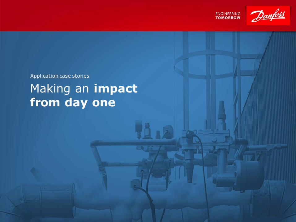
Making an impact from day one
Application case stories

23 | Industrial Refrigeration – Carsten Dahlgaard
Technical Data
• 2 air-cooled evaporator, Ammonia
• Both 41 kW @ -25C (12 TR, @ -13F)
• ICFD Defrost Module installed in an ICF 20
valve station
Land based cold storage plant in Denmark (Reitan)
Danfoss data analysis • Comparable test. Pressure vs ICFD Defrost Module • Defrost 40 min, once a day

24 | Industrial Refrigeration – Carsten Dahlgaard
Customer Benefit (end-user)
• Reduction of blow-by gas by up to 90%
• Eliminates need to re-compress blow-by gas
• Less loading of compressors
• Reduce hot gas consumption
Customer Value (end-user) • Reduced energy consumsion
Compressor energy savings
Valu
e Q
uanti
ficati
on
Custo
mer V
alu
e $
Assumptions:
Evaporator: 41 kW @ -25C (12 TR, @ -13 F)
Defrost 40 min. Once a day
Savings:12.6 kWh pr defrost
Industry current rate: EU 28 countries 2017:0.17 USD
Danish Energy Ministry: https://ens.dk/service/statistik-
data-noegletal-og-kort/priser-paa-el-og-gas
Calculation:
Evaporator/year: 12.6 x 0.17 x360
782 USD Per Evaporator /Year
(650 EUR)

25 | Industrial Refrigeration – Carsten Dahlgaard
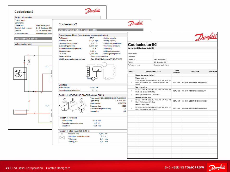
• Provides complete valve and piping calculation and selection
• Offers specific sales/order codes
• Consult Danfoss Industrial Refrigeration
experts for advice on how to optimize the defrost cycle based on the system conditions in question
• Easy download and installation
• ICFD released August 31st
Danfoss IRF Coolselector®2
Optimizes product selection and operation of the ICF Defrost Module with optimal system design
26 | Industrial Refrigeration – Carsten Dahlgaard
QuantityCode
num berType Code Sales Pr ice
1 027L3009 ICF-20-6-20DSXFXEXOXRANX62XX
1 027L5023 ICF-50-4-50DSXBXIXSXXXXX2JXX
1
1 027L4067 ICF-25-4-32DSXFXEHSXXXXX49XX
1 027L4589 ICF-15-4-20DSYFYEXD1XXXX24AX
Defros t drain line
ICF-15-4-20D DIN-EN Butt w eld DN 20. M1: Stop. M2:
Filter. M3: Solenoid. M4: Float EV
ICF-20-6-20D DIN-EN Butt w eld DN 20. M1: Stop. M2:
Filter. M3: Solenoid. M4: Manual. M5: Control. M6:
Check
Wet return line
ICF-50-4-50D DIN-EN Butt w eld DN 50. M1: Stop. M2:
Blank. M3: Solenoid. M4: Stop
Welding connection for ICF side port
Hot gas defros t line
ICF-25-4-32D DIN-EN Butt w eld DN 32. M1: Stop. M2:
Filter. M3: Solenoid. M4: Stop
Preferences used: Industrial applications
Product Descr iption
Evaporator valve s tation 1
Liquid feed line
Comments:
Created by: Niels Vestergaard
Printed: 29. November 2017
Coolselector®2Vers ion 2.1.2 | Database 22.22.1.9.5
Project name:

27 | Industrial Refrigeration – Carsten Dahlgaard
2nd EDITION REFRIGERATION CONFERENCE 2018
Bahrain 25. April 2018
Carsten Dahlgaard
TREND IN TECHNOLOGIES WITHIN INDUSTRIAL REFRIGERATION

28 | Industrial Refrigeration – Carsten Dahlgaard
Driving forces of Large Refrigeration System

29 | Industrial Refrigeration – Carsten Dahlgaard
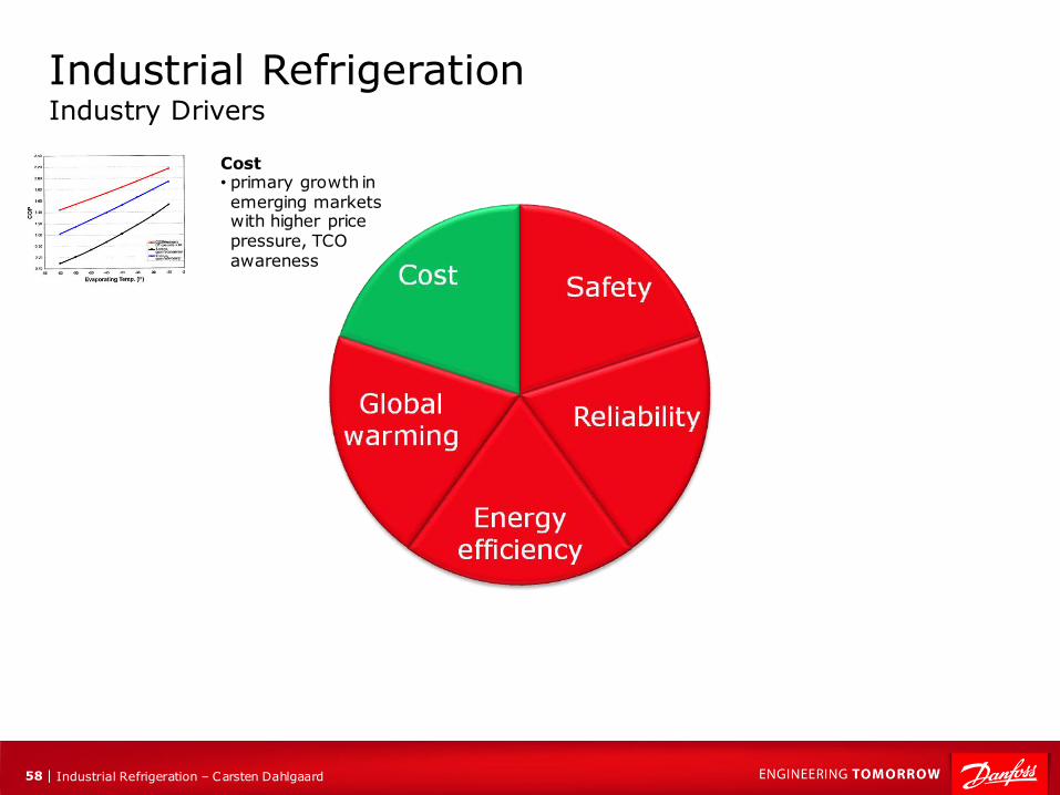
Industrial Refrigeration Industry Drivers
Reliability • Automatic running
Safety • products and
system design
Energy efficiency • new and retrofit systems
• Industriel heat pumps
Global warming • refrigerants focus,
plays along with NH3 and CO2
Cost • primary growth in emerging markets with higher price pressure, TCO awareness

30 | Industrial Refrigeration – Carsten Dahlgaard
Global warming • refrigerants focus,
plays along with NH3 and CO2

31 | Industrial Refrigeration – Carsten Dahlgaard
100.000
10.000
1.000
100
10
1,00 0,10
R507A
R422C
R410A R417A
R407C
R404A
HFC-1234ze
HFC-1234yf
R1270 (Propylene)
R744 (Carbon Dioxide)
R717 (Ammonia)
R600A (Isobutane)
R290 (Propane)
R152A
R143A
R134A
R125
R32
R23
R142B
R124
R123
R22
R115
R114
R113
R13
R12
R11
CFC
HCFC
HFC
Natural
A1 Non-toxic/non-flammable
B Toxic
2L Low flammability
2 or 3 flammable
0
4.000
0,05
Glo
ba
l W
arm
ing
Po
ten
tia
l (G
WP
)
Ozone Depletion Potential (ODP)
Source: UNEP 2010 TOC Refrigeration, A/C and Heat Pumps Assesment Report
Pending HFC developments
Refrigerant Map - outlook
Short Term
Medium to
Long Term
Kyo
to
pro
toco
l
Montreal protocol
R744 (Carbon Dioxide)
R717 (Ammonia)

32 | Industrial Refrigeration – Carsten Dahlgaard
Industrial Refrigeration Industry Drivers
Safety • products and
system design

33 | Industrial Refrigeration – Carsten Dahlgaard
E Super low-charge Ammonia system
• Install a number of
rooftop mounted self-
contained ammonia
units
R717-charge e.g.
8 x 200 kg
(0,4 kg / kW)
4 MW ammonia system
Charge: 5 kg / kW
20.000 kg
D Ammonia-CO2
• Ammonia-CO2
cascade system or
Ammonia-CO2 brine
system
R717-charge ~2.000 kg
(0,5 kg / kW)
A Increase general
safety level of
system.
• Documented risk
assessment.
• Offsite risk
assessment.
• Safety quick closing
section valves.
• Safety gas detection.
• Etc.
R717-charge
1 x 20.000 kg
(5 kg / kW)
B Sub-segments
• Design system with a
number of sub-
segments, which can
be separated from each
other in the event of
leakage.
R717-charge e.g.
4 x 5.000 kg
(5 kg / kW)
C Ammonia-DX
system
• Ammonia DX-system
reduce the required
liquid charge
R717-charge e.g.
2 x 5.000 kg
(2,5 kg / kW)
Offsite risk mitigation by charge reduction / segmentation
Charge reduction
34 | Industrial Refrigeration – Carsten Dahlgaard
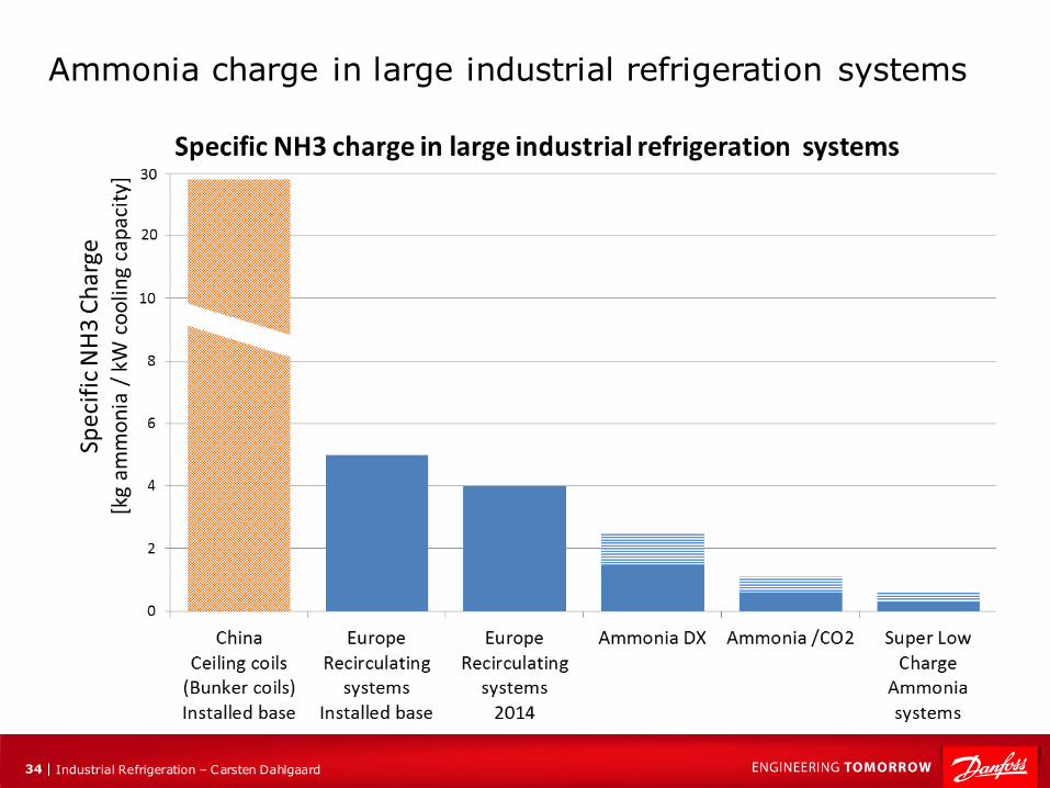
Ammonia charge in large industrial refrigeration systems

35 | Industrial Refrigeration – Carsten Dahlgaard
Reduced charge = Reduced Risk
Example: Cold Store 2300 kW
Ammonia Ceiling Coil system Ammonia DX system with Aluminum Air Coolers
Capacity, 50,000 pallets with recirculation system, room temperature, -18℃
Type of evaporators Ammonia charge (kg)
Ammonia charge
(kg /kW)
Charge reduction
(%)
U bend ceiling coil (OD,38mm; ID, 32mm) 59869 26 94%
Aluminum DX Air coolers 3680 1.6

36 | Industrial Refrigeration – Carsten Dahlgaard
Industrial Refrigeration Industry Drivers
Safety • products and
system design
Energy efficiency • new and retrofit systems
• Industriel heat pumps

37 | Industrial Refrigeration – Carsten Dahlgaard
New upcoming “Low Charge” solutions

38 | Industrial Refrigeration – Carsten Dahlgaard
Specific refrigerant charge [kg refrigerant / kW cooling]
Eff
icie
ncy “small footprint” “small footprint” “large footprint” “large footprint”
Charge reduction without compromising efficiency Impact on efficiency by concepts
Our concept
“small footprint” = short pipes “large footprint” = long pipes

39 | Industrial Refrigeration – Carsten Dahlgaard
Super low charged ammonia system for cold storages
Mitigating risks
Though not entirely new, advancements in
evaporator design and liquid feed control open
the door to NH3 systems offering
No need for an engine room
Roof-top based design
“VLC” very low NH3 charge
Claimed to have up to 98% less ammonia than regular systems (lowest charge < 100 g / kW)
Fully automated self-contained NH3 system
Very fast installation
1)
2)
3) Source: 1) http://www.foodengineeringmag.com/articles/92191-making-ammonia-safer-and-more-efficient-in-refrigeration-applications
2) http://www.ammonia21.com/web/assets/companybrochure/file/533_azanefreezer_uk.pdf 3) http://hvacpproducts.com/2015/03/evapco-introduces-evapcold-packaged-refrigeration-system/

40 | Industrial Refrigeration – Carsten Dahlgaard
Super low charged ammonia system for cold storages New upcoming trend in USA
Example: Cold storages with 6 self-contained NH3 “penthouse units” 6 x 100 kg ammonia 6 x 250 kW cooling capacity
Complet refrigerant system Evaporator
Roof

41 | Industrial Refrigeration – Carsten Dahlgaard
ChillPAC MK3 Better performance, less vibration, less charge, easy service
Compact design, small footprint, door size
Capacity: 150 – 1400 kW (Water inlet 12°C, water outlet: 7°C
Flooded evaporator with integrated liquid separator
Low refrigerant (ammonia) charge: 40 kg / 1000 kW cooling
HP-side design pressure: 28 bar (suitable as lukevarm heat pump)

42 | Industrial Refrigeration – Carsten Dahlgaard
(-37 oC)
(-23 oC)
(+2 oC)
(+35 oC)
• No liquid refrigerant in engine room • No liquid ”distribution lines” • All ”distribution lines” – dry gas • Specific charge: 1.5-3 lbm/TR (0,5-1 kg/kW)

43 | Industrial Refrigeration – Carsten Dahlgaard
Ammonia pump circulating system with regulated circulation rate
Ammonia “DX”-system with hot gas defrost & suction accumulator
Ammonia low charge systems

44 | Industrial Refrigeration – Carsten Dahlgaard
Potential: Charge reduction by regulated liquid circulation
Example based on: Cold Store: 580 kW freezing @ -35 oC and 800 kW cooling @ -5 oC total 1380 kW 14 evaporators @ -35 oC and 22 evaporators @ -5 °C
Today
~3,2 kg/kW ~1,7 kg/kW
Charge can be reduced with approx. 50%
when regulated

45 | Industrial Refrigeration – Carsten Dahlgaard
Ammonia vs. CO2/Ammonia and Glycol systems
-50 oC Temperature 0 oC
Eff
icie
ncy
NH3
NH3/CO2 cascade
NH3/CO2 secondary

46 | Industrial Refrigeration – Carsten Dahlgaard
The Heat-Transfer Efficiency Factor expresses the relation between the heat-transfer coefficient and the
necessary pump power to overcome frictional pressure losses.
CO2 <-> Secondary cooling systems Heat-Transfer
Efficiency Factor
0
20
40
60
80
100
120
-40 -35 -30 -25 -20 -15 -10 -5 0 5 10 15 20
CO2
HYCOOL 30
Temper -30
Ethylene Glycol
40,2%
Propylene Glycol
43,2%
Ammonia 17,7 %
Water
Reference:
Water + 10 Deg.C
He
at-
Tra
ns
fer
Eff
icie
nc
y F
ac
tor
[%]
[Deg. C]

47 | Industrial Refrigeration – Carsten Dahlgaard
CO2 as a brine Calculation example : Energy consumption
CO2
Propylen
Glycol CO2 Hycool
Air temperature [oC] 0 0 -20 -20
Cooling capacity [kW] 500 500 500 500
Evaporating temp [oC] -7,0 -9,5 -28,0 -32,0
Additional heat gains, [%] 7% 10% 9% 12%
Additional heat gains, [kW] 35 50 45 60
Pump power [kW] 1 14 1 16
Cooling capacity adjusted [kW] 536 564 546 576
Compressor power [kW] 130 140 251 306
Pump power [kW] 1 14 1 16
Total install [kW] 131 154 252 322
Total energy difference (CO2 vs. glycol) [%] 15% 22%

48 | Industrial Refrigeration – Carsten Dahlgaard
Pre-conditions
• Dimensioning capacity: 1000 kW @ -10 oC & 1000 kW @ - 40 oC
• Floating condensing temperature: TCmin = 15 oC for R717 & 10 oC for CO2
• Ammonia two stage open intercooler
• HT: SAB 283 S VSD
• LT: SAB 283 E male drive
• Control system: Flooded evaporators
• CO2 + Ammonia two stage cascade
• HT: SAB 283 S VSD
• LT: HPC 108 S Rotatune
• Control system: Flooded evaporators & temperature difference in cascade cooler: 5 K
• Transcritical CO2
• HT / IT: Bitzer 4CTC-30K
• LT: Bitzer 4NSL-30K
• Control system: DX
Comparison of ammonia vs. CO2 systems
Calculation based on Pack Calculation Pro ver.4.20

49 | Industrial Refrigeration – Carsten Dahlgaard
Comparison of ammonia vs. CO2 systems
100
98
108
90
95
100
105
110
115
120
Ammonia twostage open
intercooler
CO2 +Ammonia two
stage cascade
TranscriticalCO2
Com
pre
ssor
energ
y c
onsum
pti
on index
Compressor energy consumption
Denmark
100 98
117
90
95
100
105
110
115
120
Ammonia twostage open
intercooler
CO2 +Ammonia two
stage cascade
TranscriticalCO2
Com
pre
ssor
energ
y c
onsum
pti
on index
Compressor energy consumption
Rome (Italy)
(baseline) (baseline)

50 | Industrial Refrigeration – Carsten Dahlgaard
Comparison of ammonia vs. CO2 systems
Mean ambient temperature for Rome (Italy)

51 | Industrial Refrigeration – Carsten Dahlgaard
Industrial Refrigeration Industry Drivers
Energy efficiency • new and retrofit systems
• Industriel heat pumps

52 | Industrial Refrigeration – Carsten Dahlgaard
Dairies Ice Rinks Slaughter-houses
Breweries Poultry District Heating
Utilize waste heat with Ammonia Heat pumps
Ammonia – high temperature
• Pressure: up to 65 bar
• COP: up to 5 or higher as add-on
• Temperature range: water up to 95oC
• Applications: food processing, process technologies and district heating
• Capacity range: ~200 kW –> 30+ MW

53 | Industrial Refrigeration – Carsten Dahlgaard
Benefit of implementing effective control systems
Servo operated valves requires 0.2 bar
for 100% opening, and min 0.05 bar
Example: An additional pressure drop at
e.g. 0.05 bar in a suction line of an Ammonia system with an evaporating
temperature at -40 Deg. C correspond to a temperature drop on approx. 1.5 K.
Increase in compressor energy @ 0.05 bar pressure
drop in suction line. Screw compressor with Ammonia. (TE -40 to -20 Deg. C / TC +30 Deg. C)
0%
1%
2%
3%
4%
5%
6%
7%
-40 -35 -30 -25 -20
Incre
ased
kW
h [%
]
Evaporating temperature [deg. C]
Increased kWh @ 0.05 bar pressure drop
Servo operated valves vs. motorized valves

54 | Industrial Refrigeration – Carsten Dahlgaard
Industrial Refrigeration Industry Drivers
Reliability • Automatic running

55 | Industrial Refrigeration – Carsten Dahlgaard
Danfoss Flexline™ Commonalities Across ICV, ICF And SVL
• Platform based concept offering a lot of benefits such as
• Clever simplicity
• Advanced flexibility
• Timesaving efficiency
• All products are designed for Ammonia and CO2
• Standard approval for 52 bar (65 bar on request)
ICF Flexline TM
- Complete valve stations SVL Flexline TM
- Line components ICV Flexline TM
- Control valve

Industrial Refrigeration – Carsten Dahlgaard 56 |
“State of the art” Cold Store application
ICF
ICF 15-4
ICF
ICF 65-3
ICF
ICF 25-6
ICF
ICF 20-6
ICF
ICF 25-4
ICF
ICF 15-4

Industrial Refrigeration – Carsten Dahlgaard 57 |
• Provides complete valve and piping
calculation and selection
• Provides application selection (complete
evaporator station selection)
• Offers specific sales/order codes
• Easy download and installation
Coolselector®2
Fast and easy selection
58 | Industrial Refrigeration – Carsten Dahlgaard
Industrial Refrigeration Industry Drivers
Cost • primary growth in emerging markets with higher price pressure, TCO awareness

59 | Industrial Refrigeration – Carsten Dahlgaard
Maintenance cost
Installation cost
Real time monitor/control
Power consumption
First Cost of equipment
Typical CapEX budget Line
Other cost below surface More important
factors
Safety, production stop
Bad food quality
Weight loss of food
Production capacity
Operation cost
System design
Total cost of ownership for complete system
Total cost of ownership

60 | Industrial Refrigeration – Carsten Dahlgaard
Conclusion
The ammonia industry has a long history with more than 100
years of experince.
Today’s challenges:
Ammonia is still the preferred refrigerant for industrial applications
Safety is a topic, that has to be treated professional
Low charge ammonia systems is an obvious solution
Low charge solutions can be obtained by:
Re-design traditional pump-systems
Combining ammonia and CO2
Transcritical CO2
Increase energy efficiency

Industrial Refrigeration 10|