Embed Size (px)
Citation preview

Journal of Thermal Engineering, Vol. 5, No. 4, pp. 237-250, July, 2019 Yildiz Technical University Press, Istanbul, Turkey
This paper was recommended for publication in revised form by Regional Editor Alibakhsh Kasaeian 1Department of Mechanical Engineering, Kerman Branch, Islamic Azad University, Kerman, Iran. *E-mail address: [email protected] Orcid id: 0000-0002-2975-2690, 0000-0001-5947-8701 Manuscript Received 19 September 2017, Accepted 1 November 2017
MULTI-OBJECTIVE OPTIMIZATION OF A R744/R134A CASCADE
REFRIGERATION SYSTEM: EXERGETIC, ECONOMIC, ENVIRONMENTAL, AND
SENSITIVE ANALYSIS (3ES)
M.M. Keshtkar1*, P. Talebizadeh1
ABSTRACT
This work presents the optimization of a two stage-cascade refrigeration system (TS-CRS), based on
exergetic, economic, environmental, and sensitive analysis (3ES). R134a and R744 are considered as the
refrigerants of high and low temperature circuits, respectively. Two single-optimization strategies including
exergetic and economic optimizations and a multi-objective optimization are applied on the problem. In the first
step, a comprehensive performance evaluation of different effective parameters, based on the genetic algorithm,
used to indicate the optimum operative conditions in single objective strategies. In the next step, a multi-
objective optimization is performed with considering a decision-making strategy based on the Pareto frontier
using TOPSIS method. The higher exergetic efficiency and lower cost found in the exergetic and economic
single-optimization, respectively. The multi-objective optimization results demonstrate that, the total system cost
and the exergetic efficiency increase 28.6% and 99.5%, respectively, compared to the base design, and 46.6%
higher energy can be saved in the compressors.
Keywords: Cascade Refrigeration, Thermo-economic Optimization, Exergetic, Economic,
Environmental, Sensitive Analysis
INTRODUCTION
The cascade refrigeration system (CRS) is a freezing system that uses two kinds of refrigerants having
different boiling points, which circulate through their own independent refrigeration cycle and are thermally
coupled with each other through a cascade condenser [1]. This system is employed to obtain temperatures of -40
to -80°C or ultra-low temperatures [2]. At such ultra-low temperatures, a common single-refrigerant two-stage
compression system limits the low-temperature characteristics of the refrigerant to a considerably poor level,
making the system significantly inefficient [3]. The efficiency is improved by combining two kinds of
refrigerants having different temperature characteristics. Different refrigerants with suitable characteristics for
specific applications can be employed in CRSs [4]. Devotta et al. [5] carried out an experimental work based on
the replacement of propane (R290) with R22. They concluded that R290 has more COPs and less energy
consumption with respect to R22. Chen [6] replaced R22 with R410A in a residential air conditioner and showed
an improvement of about 4% on cooling capacity and 13.9% on performance coefficient. Lee et al. [7] performed
a thermodynamic investigation for a R744–R717 CRS. The optimal condensing temperature was obtained with
the aim of maximizing the COP and minimizing the exergy destruction for the cascade condenser. Bhattacharyya
et al. [8] studied a cascade cycle and determined the optimum intermediate temperature for R744/R290. Mafi et
al. [9] performed an exergy analysis for multistage CRS and found that the minimum work depends only on the
properties of incoming and outgoing process streams cooled or heated with refrigeration system and the ambient
temperature.
Another researchers showed that, thermodynamic optimization is widely used for the optimization of
energy systems [10]. Modeling and optimization of R717/R134a ice thermal energy storage air conditioning
systems using two multi-objective optimization algorithms (NSGA-II and MOPSO) studied by Rahdar et al.
[11]. The optimal design parameters which lead to the optimal objective functions (exergy efficiency and total
cost rate) achieved. By using TOPSIS decision-making method, the optimum point from Pareto frontier of each
optimization algorithm selected for both refrigerants. Najjar et al. [12] carried out a thermoeconomic analysis by
combining the energy and exergy analysis with economic analysis to evaluate the total operating cost on a novel

Journal of Thermal Engineering, Research Article, Vol. 5, No. 4, pp. 237-250, July, 2019
238
inlet air cooling system with gas turbine engines using cascaded waste-heat recovery. In this work, a
thermoeconomic analysis was done using specific exergy costing method by combining the energy and the
exergy analysis with the economic analysis to evaluate the total operating cost of the system over a wide range of
operating variables. Rezayan and Behbahaninia [13] studied a thermo-economic optimization of a R744/R717
cascade refrigeration cycle. The optimum values were calculated based on a trade-off between the capital and
input exergy costs. Raja et al. [14] used a multiobjective heat transfer search (MOHTS) algorithm and
investigated thermo-economic and thermodynamic optimization of a plate–fin heat exchanger. Effectiveness and
accuracy of the proposed algorithm were evaluated by analyzing application examples of a PFHX. The obtained
results using the proposed algorithm for thermo-economic considerations were compared with the NSGA-II and
TLBO. Dubey et al. [15] performed a thermodynamic optimization of a transcritical R744 /R1270cycle for
heating and cooling applications. Parekh et al. [16] studied a thermo-economic and cost optimizations using
R404A-R508B and determined the cost of the products. Keshtkar [17] modeled and optimized a R744/R717
cascade refrigeration system using multi-objective optimization. Toghyani et al. [18] investigated the efficiency
and the power loss due to pressure drop into the heat exchangers for a Stirling system using non-ideal adiabatic
analysis and the second-version Non-dominated Sorting Genetic Algorithm. The optimized answers were chosen
from the results using three decision-making methods. There are some other works in the literature that studied
the optimization of thermal systems [19-22].
At this work, the optimum operative condition of a R744-R134a TS-CRS has been evaluated based on
thermo-economic performance using genetic algorithm and TOPSIS decision-making procedure with Pareto
frontier. For this purpose, an exergy investigation has been performed based on thermo-economic analysis. Then,
two different optimization strategies according to exergy, economic and a multi-objective optimization as
equilibrium between cost and exergetic optimizations have been carried out. Various parameters of the system
including evaporating and condensing temperatures as well as the superheating and sub-cooling degrees of both
stages have been optimized. Exergetic, economic, environmental, and sensitive analyses (3ES) have not been
carried out so far for R134a/R744 cascade refrigeration system.
MATERIAL AND METHOD
Figure 1 and Figure 2 display a schematic diagram of a CRS using R744/R134a as the refrigerants and
the corresponding P–h diagram, respectively. The R134a and R744 are the working fluid of higher and lower
stage cycles, respectively. A detailed description of the circuits has been expressed in [19]; however, the
difference is using the R134a as a higher stage working fluid in the current study. The basic design parameters
used as a case study for the CRS have been listed in Table 1.
Figure 1. Schematic diagram of R744/R134a system.

Journal of Thermal Engineering, Research Article, Vol. 5, No. 4, pp. 237-250, July, 2019
239
Figure 2. Pressure-enthalpy diagram of R744/R134a CRS.
Table 1. Input parameters used for simulation of CRS at a basic design
Refrigeration capacity LQ 60kW
Condensing temperature CT 40 C
Evaporating temperature ET 50 C
Temperature difference in cascade condenser .Cas condT 5 C
Ambient temperature 0T 26 C
Cold room temperature CLT 27 C
The following assumptions have been taken into account:
Considering sub-cooled liquid state for the condenser and cascade condenser outlet
conditions at LT circuit.
Considering superheated vapor state for the evaporator and cascade condenser outlet
conditions at HT circuit.
Considering the adiabatic condition for the compression process within compressor
Considering the values of m e and
s for the HTC and LTC compressors equal to 0.93 and
0.73, respectively.
Negligible heat transfer between the heat exchangers and the ambient.
Considering isenthalpic condition for the throttling process within expansion valve.
Neglecting the pressure drop in pipelines and heat exchangers.
Energy and Exergy Analysis
For energy and exergy study of CRS, the needed equations have been specified in Table 2. In addition,
the performance coefficient is given as:
5 8 1 4E
HTC LTC 6 5 2 3 5 8 2 1
h -h h -hQCOP= =
W +W h -h h -h + h -h h -h (
(1)

Journal of Thermal Engineering, Research Article, Vol. 5, No. 4, pp. 237-250, July, 2019
240
The total inlet exergy to the system is given as [23]:
in LTC,comp HTC,comp fan,evap fan,condEx =W +W +W +W (
(2)
The outlet exergy (exergy of products) can be determined as:
0out L
CL
TEx = -1 Q
T
(
(3)
The overall system exergy destruction and exergetic efficiency are given as [24]:
D,total in outEx =Ex -Ex (
(4)
D,totaloutII
in in
ExExη = =1-
Ex Ex
(
(5)
Table 2. Energy and exergy study of CRS components
Component Energy Balance Exergy Balance
Evaporator L 4L 1Q = m h -h 0D,evap L 4 1 fan,evap
cl
TEx = 1- Q + Ex -Ex +w
T
LTC compressor L 2s 1 L 2 1
LTC,Comp
s m e m e
m h -h m h -h W = =
η η η η η
D,LTC,comp 1 2 LTC,compEx = Ex -Ex +W
HTC compressor
condenser
H 6s 5 H 6 5
HTC,Comp
s m e m e
m h -h m h -h W = =
η η η η η
D,LTC,comp 1 2 LTC,compEx = Ex -Ex +W
Cascade condenser 2 3HCas.cond L 2 3 H 5 8
L 5 8
h -hmQ =m h -h =m h -h , =
m h -h
D,Cascond 2 8 3 5Ex = (Ex +Ex )- Ex +Ex
Condenser
LTC expansion valve
HTC expansion valve
HH 6 7Q =m h -h
3 4h =h
7 8h =h
0D,cond H 6 7 fan,cond
0
TEx = -1 Q + Ex -Ex +W
T
D,LTC,exp 3 4Ex = Ex -Ex
D,HTC,exp 7 8Ex = Ex -Ex
Thermo-economic Analysis
Thermo-economic is the combination of exergy analysis with economic constraints. For an energy
system, the thermo-economic analysis allows one to calculate the cost rate of all streams based on
thermodynamic and economic analysis. In thermo-economic analysis, all of the stream costs are determined
through the exergy costing principles [25]. The exergy costing equation includes the cost balances for every
component. For mth component, a cost balance indicates that the total cost values related to all streams is
identical to the total cost of all streams entering and the suitable charge because of annual capital cost CI
mz ,
maintenance cost and annual operating OM
mz , and annual penalty cost ENV
mz in terms of US$ per year. Note
that in this analysis, as mentioned, the input exergy cost of each component is equal to the output rate of previous
component. Therefore, the unknown quantity in the equation is the product’s exergy cost. The system’s total cost
is given as [25]:

Journal of Thermal Engineering, Research Article, Vol. 5, No. 4, pp. 237-250, July, 2019
241
total out out w in in Q Q m
m
C = c Ex +c W= c Ex +c Ex + Z (
(6)
In Eq. (6), the place of heat and work can change as production or input according to the system
conditions. In the exergy costing equation,totalC is the sum yearly cost of the system;
ic and oc are the unit costs
of the input and product exergy, respectively. inEx and
outEx are the annual exergy rates from internal sources
and output products, respectively. In TS-CRS, the input exergy is only the electrical energy, while the product is
cooling capacity. The capital cost of each component CI
mz is given as [26]:
0.46
HTC,comp HTC,compZ =9624.2 W (
(7)
0.46
LTC,comp LTC,compZ =10167.5 W (
(8)
0.89 0.76
cond cond fan,condZ =1397A +629.05 W (
(9)
0.89 0.76
evap evap fan,evapZ =1397A +629.05 W (
(10)
0.68
cas,cond cas,condZ =2382.9A (
(11)
In engineering economics, by introducing the capital recovery factor (CRF), the time interval unit
considered for the capital cost calculation is commonly considered as a year and determined as [25]:
n
n
i(1+i)CRF=
(1+i) -1
(
(12)
At the present work, the rate of interest ( )i and the system life ( )n are assumed 14% and 15 years,
respectively. According to the investment cost ($)mz , the common function for the cost rate, z $ / sm ,
related to capital cost and the maintenance cost for thethm is given as:
mm
Z ×CRF×fZ =
N×3600
(
(13)
At this work, the values of the maintenance factor ( ), the system yearly hours of operation ( N ), and
CRF are considered 1.06, 8000 h and 18.2%, respectively. After obtaining the cost rate for all components, the
total annual cost rate is given as:

Journal of Thermal Engineering, Research Article, Vol. 5, No. 4, pp. 237-250, July, 2019
242
2 2
tot HTC,comp LTC,comp cond evap cas,cond
elec,peak elec,mid-peak
HTC,comp LTC,comp Fan,LTC Fan,HTC
Co Co
C = Z +Z +Z +Z +Z +
c c1 2W +W +W +W × + +
3 3600 3 3600
m 1000 c×
N 3600
(
(14)
where value of ,elec peakc , is 0.07 $kWh-1, and ,elec mid peakc is 0.04 $kWh-1, which are the unit costs of
electricity during the working hours for the peak and the mid-peak time, respectively. Note that the 1/3 and 2/3
coefficients show the electricity use in the peak and the mid-peak. 2Com kg is the amount of
2CO emission and
is determined from the annual electricity consumption[ ]kWh , using the emission conversion factor equal to
10.968kgkWh . At the present work, the unit environmental cost of emission of carbon dioxide 2
( )Coc is
assumed 290 $US tonCo [26].
Heat Exchanger Design
Since the annual cost of CRS depends on the pressure drop and thermal area of heat exchangers, the
design of the employed heat exchangers including evaporator, air-cooled, and cascade condensers is important
[27]. Evaporator and air-cooled condenser are compact air-cooled heat exchangers. The cascade condenser is a
double-pipe heat exchanger. For designing of heat exchangers, the number of tube rows, tube diameter, and tube
thickness are important. At the present work, for heat transfer and pressure drop calculations, the library
functions in EES (Engineering Equation Solver) were used [28]. The heat transfer area for every heat exchanger
is given as:
o oA = Q U LMTD (
(15)
The overall coefficient of heat transfer ( )OU regarding the external heat transfer area and the
logarithmic temperature are given as:
0
hot,i cold,o hot,o cold,ii
o o i i o o hot,i cold,o
hot,o cold,i
dln T -T - T -Td1 1 1
= + + , LMTD=U A h A h A 2πLk T -T
lnT -T
(
(16)
Figure 3 shows a compact tube-fin, cross-flow heat exchanger used in the present work for the
evaporator, and air-cooled condenser. The geometric parameters have been shown in Fig. 3. The fins have been
made from copper with a thickness offinth and a fin pitch of
finp . The heat exchanger includes 10 rows of tubes
in two columns connected in series. The vertical and horizontal spacing between adjacent tubes is vs and
hs ,
respectively. The heat exchanger length in the direction of the airflow is L, and the width and height of the front
face are W and H, respectively. The tubes have been made from copper with outer diameter of 𝐷𝑜𝑢𝑡 and wall
thickness, th . The roughness of the tube inner surface is 10e m . Clean dry air passes through the heat
exchanger perpendicular to the tubes with a volumetric flow rate of 30.06cV m s . Table 3 shows the
geometric parameters of the condenser and evaporator. The pressure drop of the air regarding the compact tube-
fin heat exchanger is given as:

Journal of Thermal Engineering, Research Article, Vol. 5, No. 4, pp. 237-250, July, 2019
243
2
2flow in in
in h out in out
4L ρ ρG 1 1 1 1Δp= f + 1+σ -1 , = +
2ρ D ρ ρ ρ 2 ρ ρ
(
(17)
G is mass velocity, andi ,
o , and are, the inlet, outlet, and mean air density, respectively. f is
the coefficient of friction presented in [29]. More information on the subject of air-side and tube-side pressure
drop and heat transfer calculations for all heat exchangers are found at [30-32]. It should be noted that, selection
of cascade condenser model has been carried out based on pre-defined models in EES library [28]. At the
double-pipe heat exchanger, the fluid in inner pipe is considered R744 and in annual space is R134a.
Table 3. Geometry specifications of evaporator and condenser at this work.
Component Outside
diameter (m)
Tube thickness
(mm)
Fin
thickness
(mm)
Horizontal
pitch (mm)
Vertical pitch
(mm)
Number of tube
rows
Evaporator 0.0102 0.9 0.33 22 25.4 10
Condenser 0.0159 0.9 0.33 22 25.4 10
Figure 3. Schematic of evaporator and condenser.
SYSTEM OPTIMIZATION WITH NSGA-II
For the thermo-economic optimization, six independent parameters have been shown in Table 4. These
parameters are chosen as the decision making variables within the defined range. The maximum and minimum
values for each design parameter have been applied as the constraints. The loaded optimization limitations of the
key design parameters have been indicated according to the proposed rates from the literature [25].
Two different objective functions have been employed as the optimization strategies; the total cost rate
( )totC and the exergy efficiency ( )II of CRS. The exergy efficiency represents the thermodynamic
irreversibility due to the heat transfer extracted by the variation of temperature in various components. The
following multi-linear regression equations are fitted on the EES achieved data:
2 2
3 sub,L 4 sub,L 5 sup,H 6 sup,H
2
II 0 1 sub,H 2 sub,H
C C
2 2 2
7 sup,L 8 sup,L 9 10 11 E 12 E
+a ΔT +a ΔT +a ΔT +a ΔT
+a
η =a
ΔT +a ΔT +a T +a T +a T +
+a ΔT
a
+ T
T
a Δ
(
(18)

Journal of Thermal Engineering, Research Article, Vol. 5, No. 4, pp. 237-250, July, 2019
244
2 2
3 sub,L 4 sub,L 5 sup,H 6 sup,H
2 2 2
7 sup,L 8 sup,L 9
2
total 0 1 su
10 11 E 12
b,H 2 sub,H
C C E
C +b ΔT +b ΔT +b ΔT +b ΔT
+b ΔT +b ΔT +b
=b +b ΔT
T +b T +b T +b
b ΔT
T
+ (
(19)
The multi-linear regression coefficients for Eqs. (18) and (19) have been given in Table 5. The root
mean square errors and coefficients of correlations have been calculated equal to 1.076E-03 and 99.48% for Eq.
(18) and 4.309E-05 and 97.15% for Eq. (19), respectively [33].
Table 4. Decision variables for TS-CRS and their corresponding range of variation.
Decision variables Range of variation
Condensing temperature of R134a o o
C38 C<T <48 C
Evaporating temperature of R744 o o
E-60 C<T <-40 C
Degree of superheating at R744circuit o o
sup,LTC0 C<ΔT <20 C
Degree of subcooling at R744circuit o o
sub,LTC0 C<ΔT <10 C
Degree of superheating at R134a circuit o o
sup,HTC0 C<ΔT <20 C
Degree of subcooling at R134a circuit o o
sub,HTC0 C<ΔT <10 C
Table 5. Coefficients of Eqs. (18 and 19) using Multi-linear regression.
II 0a
1a 2a
3a 4a
5a 6a
7a 8a
9a 10a
11a 12a
Values -1.6468
E+00
1.5169
E+00
3.4059
E-03
9.1870
E-01
2.6264
E-01
-1.0013
E-01
-8.2059
E-03
-1.2031
E+00
-9.5615
E-03
1.3121
E-01
3.3807
E-03
-7.8029
E-04
1.6868
E-03
totC 0b
1b 2b
3b 4b
5b 6b
7b 8b
9b 10b
11b 12b
Values 5.8974
E-03
-1.1183
E-04
-5.2061
E-05
6.0660
E-04
-1.1655
E-04
2.8431
E-05
1.7375
E-05
-9.5376
E-05
5.0526
E-05
-3.5672
E-05
-4.2426
E-07
-1.2371
E-04
2.2200
E-06
It is noticeable that for optimization of the system, the exergy efficiency (Eq. 18) should be maximized,
while the total cost rate (Eq. 19) should be minimized. To optimization of the CRS, a NSGA-II genetic algorithm
method has been used. In engineering optimization, genetic algorithms can establish reasonable solutions with
random initialization [34]. Genetic algorithm is a non-deterministic optimization technique with general-purpose
search method based on the principles of evolution including the crossover, selection, and mutation operators
with the aim of presenting the optimal solution in a population to achieve an identified criterion of termination.
The setting parameters in GA optimization method have been given in Table 6.
Table 6. The setting parameters in the optimization process
Setting parameters value
Population size 500
Maximum number of generation 400
Minimum function tolerance 5-10
Probability of crossover 90%
Probability of mutation 1%
Number of crossover point 2
Selection process Tournament
Tournament size 2
Note that an in-house computer code software has been developed in MATLAB to achieve the Pareto
frontier. The Pareto frontier solution indicates the optimal solutions, and one of these solutions is selected as the

Journal of Thermal Engineering, Research Article, Vol. 5, No. 4, pp. 237-250, July, 2019
245
best solution in this work using a decision-making technique. TOPSIS is a decision-making technique for finding
the closest result to the ideal solution defined in the following argument.
In this method since the dimension of various objectives might be different, first, the scales and
dimension of objectives space must be non-dimensionalized. So, a non-dimensionalized objective,n
ijF , is
introduced as:
ijn
ijm
22
ij
i=1
for minimizing and maximizing objectF
F =
(F )
(20)
Decision making in the TOPSIS method is performed by calculating each solution’s distance on the
Pareto frontier from the best point indicated by id
and from the non-ideal point indicated by id
as following
[35]:
2
1
( )n
Ideal
i ij j
j
d F F
(21)
2
1
( )n
Non Ideal
i ij j
j
d F F
(22)
where n shows the objectives; i stands for every solution on the frontier of Pareto (i=1,2,….,m).Ideal
jF
andNon Ideal
jF are the ideal and non-ideal values for
thj objective calculated from a single-objective
optimization, respectively. In the non-ideal point, every objective possesses its worst value. Therefore, a iCl
variable is also explained as:
i
i
i i
dCl
d d
(23)
Finally, a solution with minimum iCl is chosen as a suitable solution.
RESULTS AND DISCUSSION
To find the effect of various parameters on the COP of the system, the exergy destruction value of all
components ( )DEx , the exergetic efficiency ( )II , and the overall system’s cost are first analyzed. A sensitive
analysis is carried out before the optimization process. The evaporation, condensation, sub-cooling, and
superheating temperature in both cycle have been selected as the most effective parameters in CRS cycle.
Furthermore, their variations are much more important than other parameters.
Figure 4 shows the effect of evaporating temperature in R134a circuit ,( )CAS ET on the COP of the
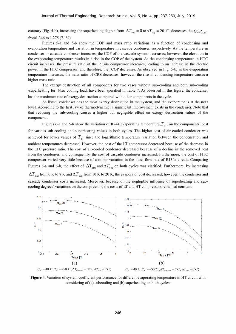
system at the given operating conditions. Figs.4-a and 4-b display the variation of COP at different values of sub-
cooling and superheating degrees, respectively. It can be seen that the MAXCOP increased as the degree of sub-
cooling increased. Furthermore, increasing the sub-cooling degree from 0subT to 10subT C enhanced in
the MAXCOP from 1.342 to 1.445, i.e. a 10.3% increase with respect to its value without sub-cooling. On the
Journal of Thermal Engineering, Research Article, Vol. 5, No. 4, pp. 237-250, July, 2019
246
contrary (Fig. 4-b), increasing the superheating degree from sup 0T to
sup 20T C decreases the MAXCOP
from1.346 to 1.275 (7.1%).
Figures 5-a and 5-b show the COP and mass ratio variations as a function of condensing and
evaporation temperature and variation in temperature in cascade condenser, respectively. As the temperature in
condenser or cascade condenser increases, the COP of the cascade system decreases; however, the elevation in
the evaporating temperature results in a rise in the COP of the system. As the condensing temperature in HTC
circuit increases, the pressure ratio of the R134a compressor increases, leading to an increase in the electric
power in the HTC compressor, and therefore, the COP decreases. As observed in Fig. 5-b, as the evaporating
temperature increases, the mass ratio of CRS decreases; however, the rise in condensing temperature causes a
higher mass ratio.
The exergy destruction of all components for two cases without sub-cooling and both sub-cooling
/superheating for 60kw cooling load, have been specified in Table 7. As observed in this figure, the condenser
has the maximum rate of exergy destruction compared with other components in the cycle.
As listed, condenser has the most exergy destruction in the system, and the evaporator is at the next
level. According to the first law of thermodynamic, a significant improvement exists in the condenser. Note that
that reducing the sub-cooling causes a higher but negligible effect on exergy destruction values of the
components.
Figures 6-a and 6-b show the variation of R744 evaporating temperature,ET , on the components’ cost
for various sub-cooling and superheating values in both cycles. The higher cost of air-cooled condenser was
achieved for lower values of ET since the logarithmic temperature variation between the condensation and
ambient temperatures decreased. However, the cost of the LT compressor decreased because of the decrease in
the LTC pressure ratio. The cost of air-cooled condenser decreased because of a decline in the removed heat
from the condenser, and consequently, the cost of cascade condenser increased. Furthermore, the cost of HTC
compressor varied very little because of a minor variation in the mass flow rate of R134a circuit. Comparing
Figures 6-a and 6-b, the effect of subT and supT on both cycles was clarified. Furthermore, by increasing
subT from 0 K to 8 K and supT from 10 K to 20 K, the evaporator cost decreased; however, the condenser and
cascade condenser costs increased. Moreover, because of the negligible influence of superheating and sub-
cooling degrees’ variations on the compressors, the costs of LT and HT compressors remained constant.
(a)
sup( 40 , 50 , 5 , 0 )C E CascondT C T C T C T C (b)
su( 40 , 50 , 5 , 0 )C E Cascond bT C T C T C T C
Figure 4. Variation of system coefficient performance for different evaporating temperature in HT circuit with
considering of (a) subcooling and (b) superheating on both cycles.

Journal of Thermal Engineering, Research Article, Vol. 5, No. 4, pp. 237-250, July, 2019
247
(a) (b)
Figure 5. Effect of evaporating ET , condensing CT , evaporating temperature in R134a cycle CAS,ET
and temperature difference in cascade condenser CAST on (a) system performance and (b) mass ratio at
various conditions.
Table7. The exergy destruction rates ( )kW for cooling load of 60kw .
Component HTC
Comp.
LTC
Comp. Condenser Evaporator
Cascade
Cond.
HTC
Ex.
Valve
LTC
Ex.
Valve
( 8 , 10 )sub supT C T C 2.1 2.4 10.2 5.6 0.7 0.2 0.1
( 0 , 10 )sub supT C T C 2.3 2.6 10.7 5.9 0.85 0.25 0.15
(a)
sup0, 10subT T C (b) sup8 , 20subT C T C
Figure 6. Effect of R744 evaporating temperature on the costs of system components
,( 40 , 5 , 5 )C Cascond CAS ET C T C T C
Figures 7-a and 7-b show the variation of ,sub LT and ,sub HT , i.e. the sub-cooling degrees in
low and high temperature circuits on the annual total cost and exergetic efficiency of the CRS. By
increasing ,sub LT or ,sub HT , the exergetic efficiency and annual overall cost rose. Furthermore, an
optimum point for sub-cooling degree can be found by carrying out a trade-off between the annual total
cost and the system’s exergetic efficiency.

Journal of Thermal Engineering, Research Article, Vol. 5, No. 4, pp. 237-250, July, 2019
248
The variations of sup,LT and sup,HT , i.e. the superheating degrees in low and high temperature
circuits on the annual total cost and exergetic efficiency of the CRS have been shown in Figs.7-c and 7-d.
Increasing sup,LT orsup,HT decreases the annual total cost and exergetic efficiency. However,
comparing Figures 7-c and 7-d, optimum points for superheating degree can be obtained by performing a
trade-off between the total cost and exergetic efficiency of the system.
(a) (b)
(c) (d)
Figure 7. Variations of annual cost and exergetic efficiency of the system versus the (a- b) subcooling
degree and (c-d) superheating degree in low and high temperature circuits
,( 40 , 50 , 5 , 5 )C E Cascond CAS ET C T C T C T C

Journal of Thermal Engineering, Research Article, Vol. 5, No. 4, pp. 237-250, July, 2019
249
Figure 8. Pareto optimal frontier from multi-objective optimization of R134A/R744 CRS.
CONCLUSION
In the present work, R134a/R744 cascade refrigeration system, based on exergetic, economic,
environmental, and sensitive analysis (3ES) was modeled and analyzed. A multi-objective optimization was also
done regarding the Pareto frontier employing NSGA-II optimization and a decision-making strategy. The
findings showed that by enhancing ,sub LT or ,sub HT , the exergetic efficiency and the total annual cost of the
CRS increased. Furthermore, according to single objective optimizations, the exergetic efficiency increased by
94.8%, resulting from 38.7% decrease in the total cost, using the exergetic optimization, in comparison to the
base design. The total system cost decreased by 10.3%, using the cost optimization, and the exergetic efficiency
increased by 20.6%. The higher cost of air-cooled condenser was achieved for lower values of ET since the
logarithmic temperature variation between the condensation and ambient temperatures decreased. However, the
cost of the LT compressor decreased because of the decrease in the LTC pressure ratio. The cost of air-cooled
condenser decreased because of a decline in the removed heat from the condenser, and consequently, the cost of
cascade condenser increased. The findings of multi-objective optimization demonstrated that the exergetic
efficiency and the overall annual system expense increased 99.5% and 28.6%, respectively, and 46.6% higher
energy was saved in both compressors.
REFERENCES
[1] Getu, H. M., Bansal, P. K. (2006). Simulation model of a low-temperature supermarket refrigeration system.
HVAC&R Research, 12(4), 1117-1139.
[2] Getu, H. M., Bansal, P. K. (2008). Thermodynamic analysis of an R744–R717 cascade refrigeration system.
International journal of refrigeration, 31(1), 45-54.
[3] Messineo, A. (2012). R744-R717 cascade refrigeration system: performance evaluation compared with a
HFC two-stage system. Energy Procedia, 14, 56-65.
[4] Pearson, A. (2001). New developments in industrial refrigeration. Ashrae Journal, 43(3), 54.
[5] Devotta, S., Padalkar, A. S., Sane, N. K. (2005). Performance assessment of HC-290 as a drop-in substitute
to HCFC-22 in a window air conditioner. International Journal of Refrigeration, 28(4), 594-604.
[6] Chen, W. (2008). A comparative study on the performance and environmental characteristics of R410A and
R22 residential air conditioners. Applied thermal engineering, 28(1), 1-7.
[7] Lee, T. S., Liu, C. H., Chen, T. W. (2006). Thermodynamic analysis of optimal condensing temperature of
cascade-condenser in CO2/NH3 cascade refrigeration systems. International Journal of Refrigeration, 29(7),
1100-1108.
[8] Bhattacharyya, S., Bose, S., Sarkar, J. (2007). Exergy maximization of cascade refrigeration cycles and its
numerical verification for a transcritical CO2–C3H8 system. International Journal of Refrigeration, 30(4), 624-
632.
[9] Mafi, M., Naeynian, S. M., Amidpour, M. (2009). Exergy analysis of multistage cascade low temperature
refrigeration systems used in olefin plants. International journal of refrigeration, 32(2), 279-294.

Journal of Thermal Engineering, Research Article, Vol. 5, No. 4, pp. 237-250, July, 2019
250
[10] Keshtkar, M. M., Talebizadeh, P. (2017). Multi-objective optimization of cooling water package based on
3E analysis: A case study. Energy, 134, 840-849.
[11] Rahdar, M. H., Heidari, M., Ataei, A., Choi, J. K. (2016). Modeling and optimization of R-717 and R-134a
ice thermal energy storage air conditioning systems using NSGA-II and MOPSO algorithms. Applied Thermal
Engineering, 96, 217-227.
[12] Najjar, Y. S., Abubaker, A. M. (2017). Thermoeconomic analysis and optimization of a novel inlet air
cooling system with gas turbine engines using cascaded waste-heat recovery. Energy, 128, 421-434.
[13] Rezayan, O., Behbahaninia, A. (2011). Thermoeconomic optimization and exergy analysis of CO2/NH3
cascade refrigeration systems. Energy, 36(2), 888-895.
[14] Raja, B. D., Jhala, R. L., Patel, V. (2018). Multiobjective thermo‐ economic and thermodynamics
optimization of a plate–fin heat exchanger. Heat Transfer—Asian Research, 47(2), 253-270.
[15] Dubey, A. M., Kumar, S., Agrawal, G. D. (2014). Thermodynamic analysis of a transcritical CO2/propylene
(R744–R1270) cascade system for cooling and heating applications. Energy conversion and management, 86,
774-783.
[16] Parekh, A. D., Tailor, P. R., Sutaria, N. (2012). Thermoeconomic Optimization of Cascade Refrigeration
System using Refrigerant Pair R404A-R508B. In Applied Mechanics and Materials (Vol. 110, pp. 677-684).
Trans Tech Publications.
[17] Keshtkar, M. M. (2016). Effect of subcooling and superheating on performance of a cascade refrigeration
system with considering thermo-economic analysis and multi-objective optimization. Journal of Advanced
Computer Science and Technology, 5(2), 42-47.
[18] Toghyani, S., Kasaeian, A., Ahmadi, M. H. (2014). Multi-objective optimization of Stirling engine using
non-ideal adiabatic method. Energy Conversion and Management, 80, 54-62.
[19] Sadatsakkak, S. A., Ahmadi, M. H., Ahmadi, M. A. (2015). Optimization performance and thermodynamic
analysis of an irreversible nano scale Brayton cycle operating with Maxwell–Boltzmann gas. Energy Conversion
and Management, 101, 592-605.
[20] Kaushik, S. C., Kumar, R., Arora, R. (2016). Thermo-economic optimization and parametric study of an
irreversible regenerative Brayton cycle. Journal of Thermal Engineering (ICES2015).
[21] Heidarnejad, P. (2017). Exergy Based Optimization of a Biomass and Solar Fuelled CCHP Hybrid Seawater
Desalination Plant. Journal of Thermal Engineering, 3(1), 1034-1043.
[22] Keshtkar, M. M. (2017). Performance analysis of a counter flow wet cooling tower and selection of
optimum operative condition by MCDM-TOPSIS method. Applied Thermal Engineering, 114, 776-784.
[23] Wouagfack, P. A. N., Tchinda, R. (2011). Irreversible three-heat-source refrigerator with heat transfer law of
QαΔ (T− 1) and its performance optimization based on ECOP criterion. Energy Systems, 2(3-4), 359-376.
[24] Kotas, T. J. (1986). Exergy method of thermal and chemical plant analysis. Trans IChemE, 64, 212-229.
[25] Bejan, A., Tsatsaronis, G., Moran, M., Moran, M. J. (1996). Thermal design and optimization. John Wiley
& Sons.
[26] Aminyavari, M., Najafi, B., Shirazi, A., Rinaldi, F. (2014). Exergetic, economic and environmental (3E)
analyses, and multi-objective optimization of a CO2/NH3 cascade refrigeration system. Applied Thermal
Engineering, 65(1-2), 42-50.
[27] Rao, R. V., Saroj, A. (2018). Multi-objective design optimization of heat exchangers using elitist-Jaya
algorithm. Energy Systems, 9(2), 305-341.
[28] Klein, S. A., Alvarado, F. L. (1992). EES: Engineering equation solver for the Microsoft Windows operating
system. F-Chart software.
[29] Nellis, G., Klein, S. (2009). Mass transfer. Heat Transfer, Cambridge University Press, New York.
[30] Kays, W.M., London, A.L., “Compact Heat Exchangers”, Krieger Publishing Company, (1984).
[31] Shah, R.K., Sekulic, D.P., “Fundamentals of Heat Exchanger Design”, Wiley, (2003)
[32] Thirumaleshwar, M., “Software Solutions to Problems on Heat Transfer - Boiling and Condensation”,
(2013)
[33] Harrell Jr, F. E. (2015). Regression modeling strategies: with applications to linear models, logistic and
ordinal regression, and survival analysis. Springer.
[34] Konak, A., Coit, D. W., Smith, A. E. (2006). Multi-objective optimization using genetic algorithms: A
tutorial. Reliability Engineering & System Safety, 91(9), 992-1007.
[35] Holland, J. H. (1992). Adaptation in natural and artificial systems: an introductory analysis with applications
to biology, control, and artificial intelligence. MIT press.