Embed Size (px)
Citation preview
Prepared for:
Indiana University and the Indiana Office of Community and Rural Affairs (OCRA)
in Support of the Development of the Indiana Fluvial Erosion Hazard Mitigation Manual, an Indiana Silver Jackets Initiative
October 2018
Prepared by:
Christopher B. Burke Engineering, LLC 115 West Washington Street, Suite 1368 South
Indianapolis, Indiana 46204
CBBEL Project No. 14-0014.00000
DANDY TRAIL SITE FEH MITIGATION ALONG EAGLE CREEK

Dandy Trail Site FEH Mitigation October 2018 along Eagle Creek
i
Table of Contents Page
Table of Contents .................................................................................... i
Executive Summary .............................................................................. iii
Project Overview .................................................................. 1 1.1 Introduction ................................................................................................... 1 1.2 Project History ............................................................................................... 1 1.3 Project Purpose ............................................................................................ 2 1.4 Analysis Process ........................................................................................... 2
Data Gathering ..................................................................... 3 2.1 Sources of Data ............................................................................................ 3 2.2 Previous Studies ........................................................................................... 4
FEH Mitigation Study ........................................................... 5 3.1 Identification of Assessment Reach .............................................................. 5 3.2 Site Assessment ........................................................................................... 6 3.3 Watershed-scale Assessment ....................................................................... 6 3.4 Reach-scale Assessment ............................................................................ 10 3.5 Key Findings of FEH Mitigation Study ......................................................... 12
Stakeholder Input and Mitigation Objectives .................. 13 4.1 Decision Making Process ............................................................................ 13 4.2 Mitigation Objectives ................................................................................... 13 4.3 Prioritized Mitigation Objectives & Performance Metrics ............................. 14
Passive Management Considerations ............................. 15
Active River Management Analysis ................................. 16 6.1 Vertical Stability Considerations .................................................................. 16 6.2 Lateral Stability Considerations ................................................................... 16 6.3 Proposed Mitigation Measures .................................................................... 17
Recommendations ............................................................. 20 7.1 Monitoring ................................................................................................... 20 7.2 Improvement Implementation ...................................................................... 20 7.3 Next Steps .................................................................................................. 20
References .......................................................................... 21
Dandy Trail Site FEH Mitigation October 2018 along Eagle Creek
ii
List of Tables and Figures Table 1: Comparison of Observed Channel Properties with Regional Curves ........... 7 Table 2: Risk Level Criteria ........................................................................................ 8 Table 3: Identification of Fluvial Erosion Hazards ...................................................... 8 Table 4: Triple Bottom Line Comparison of Improvement Alternatives .................... 17 Figure 1: Stream Bank Along Eagle Creek Levee ...................................................... 1 Figure 2: Failed Streambank above Revetment at FEH Site ..................................... 2 Figure 3: Preliminary Assessment Reach .................................................................. 5 Figure 4: Controlled vs. Natural Flow ......................................................................... 6 Figure 5: Eagle Creek Dam ........................................................................................ 7 Figure 6: Locations of At-Risk Infrastructure .............................................................. 9 Figure 7: Overflow Path near FEH Site .................................................................... 10 Figure 8: Toe Protection Measures .......................................................................... 16 Figure 9: Armored Channel in Indianapolis, IN ........................................................ 17
List of Exhibits Exhibit 1 – Study Area Map Exhibit 2 – Topographic Map of Eagle Creek Watershed Exhibit 3 – Map of Unstable Slopes Exhibit 4 – Levee Conceptual Improvements
List of Appendices Appendix 1: Site Observation Photographs Appendix 2: Site Assessment Data & Calculations Appendix 3: Watershed-scale Assessment Data & Calculations Appendix 4: Reach-scale Assessment Data & Calculations Appendix 5: Triple Bottom Line and Cost Estimate Calculations
Dandy Trail Site FEH Mitigation October 2018 along Eagle Creek
iii
EXECUTIVE SUMMARY
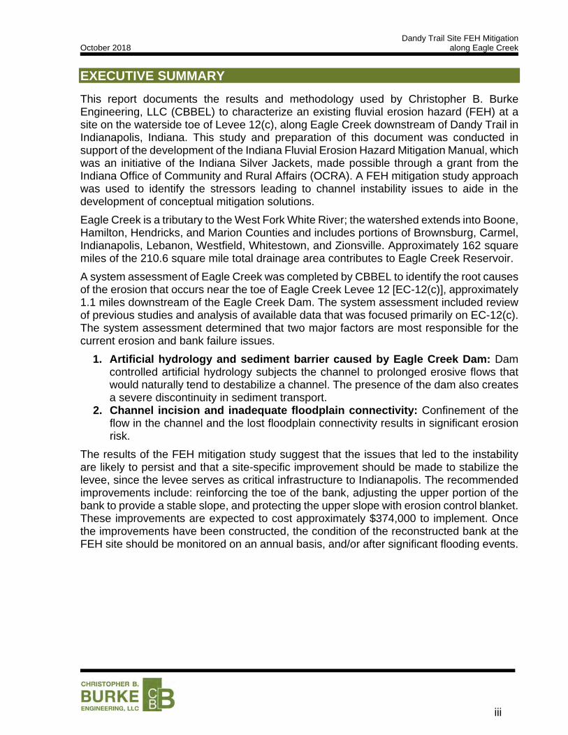
This report documents the results and methodology used by Christopher B. Burke Engineering, LLC (CBBEL) to characterize an existing fluvial erosion hazard (FEH) at a site on the waterside toe of Levee 12(c), along Eagle Creek downstream of Dandy Trail in Indianapolis, Indiana. This study and preparation of this document was conducted in support of the development of the Indiana Fluvial Erosion Hazard Mitigation Manual, which was an initiative of the Indiana Silver Jackets, made possible through a grant from the Indiana Office of Community and Rural Affairs (OCRA). A FEH mitigation study approach was used to identify the stressors leading to channel instability issues to aide in the development of conceptual mitigation solutions.
Eagle Creek is a tributary to the West Fork White River; the watershed extends into Boone, Hamilton, Hendricks, and Marion Counties and includes portions of Brownsburg, Carmel, Indianapolis, Lebanon, Westfield, Whitestown, and Zionsville. Approximately 162 square miles of the 210.6 square mile total drainage area contributes to Eagle Creek Reservoir.
A system assessment of Eagle Creek was completed by CBBEL to identify the root causes of the erosion that occurs near the toe of Eagle Creek Levee 12 [EC-12(c)], approximately 1.1 miles downstream of the Eagle Creek Dam. The system assessment included review of previous studies and analysis of available data that was focused primarily on EC-12(c). The system assessment determined that two major factors are most responsible for the current erosion and bank failure issues.
1. Artificial hydrology and sediment barrier caused by Eagle Creek Dam: Dam controlled artificial hydrology subjects the channel to prolonged erosive flows that would naturally tend to destabilize a channel. The presence of the dam also creates a severe discontinuity in sediment transport.
2. Channel incision and inadequate floodplain connectivity: Confinement of the flow in the channel and the lost floodplain connectivity results in significant erosion risk.
The results of the FEH mitigation study suggest that the issues that led to the instability are likely to persist and that a site-specific improvement should be made to stabilize the levee, since the levee serves as critical infrastructure to Indianapolis. The recommended improvements include: reinforcing the toe of the bank, adjusting the upper portion of the bank to provide a stable slope, and protecting the upper slope with erosion control blanket. These improvements are expected to cost approximately $374,000 to implement. Once the improvements have been constructed, the condition of the reconstructed bank at the FEH site should be monitored on an annual basis, and/or after significant flooding events.
Dandy Trail Site FEH Mitigation October 2018 along Eagle Creek
1
PROJECT OVERVIEW
1.1 INTRODUCTION
This report documents the results and methodology used by Christopher B. Burke Engineering, LLC (CBBEL) to identify the need and ability to mitigate an existing fluvial erosion hazard (FEH) along the waterside toe of Levee 12(c) along Eagle Creek just downstream of Dandy Trail in Indianapolis, Indiana. This study and preparation of this document was conducted in support of the development of the Indiana Fluvial Erosion Hazard Mitigation Manual. The development of the Manual was an initiative of the Indiana Silver Jackets, made possible through a grant from the Indiana Office of Community and Rural Affairs (OCRA). A system-based approach was used to identify the stressors leading to channel instability issues to aide in the development of conceptual mitigation solutions.
1.2 PROJECT HISTORY
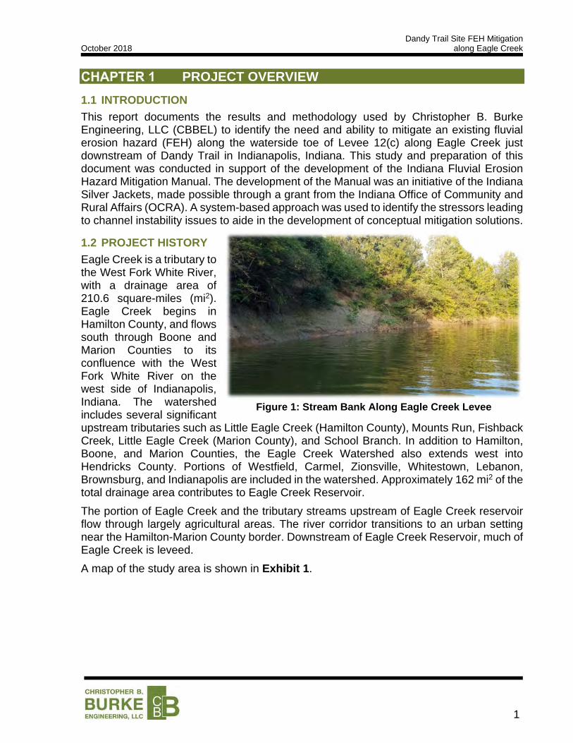
Eagle Creek is a tributary to the West Fork White River, with a drainage area of 210.6 square-miles (mi2). Eagle Creek begins in Hamilton County, and flows south through Boone and Marion Counties to its confluence with the West Fork White River on the west side of Indianapolis, Indiana. The watershed includes several significant upstream tributaries such as Little Eagle Creek (Hamilton County), Mounts Run, Fishback Creek, Little Eagle Creek (Marion County), and School Branch. In addition to Hamilton, Boone, and Marion Counties, the Eagle Creek Watershed also extends west into Hendricks County. Portions of Westfield, Carmel, Zionsville, Whitestown, Lebanon, Brownsburg, and Indianapolis are included in the watershed. Approximately 162 mi2 of the total drainage area contributes to Eagle Creek Reservoir.
The portion of Eagle Creek and the tributary streams upstream of Eagle Creek reservoir flow through largely agricultural areas. The river corridor transitions to an urban setting near the Hamilton-Marion County border. Downstream of Eagle Creek Reservoir, much of Eagle Creek is leveed.
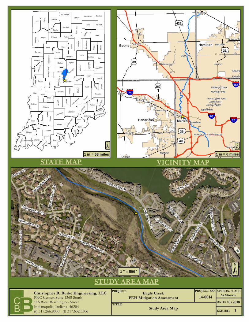
A map of the study area is shown in Exhibit 1.
Figure 1: Stream Bank Along Eagle Creek Levee
Dandy Trail Site FEH Mitigation October 2018 along Eagle Creek
2
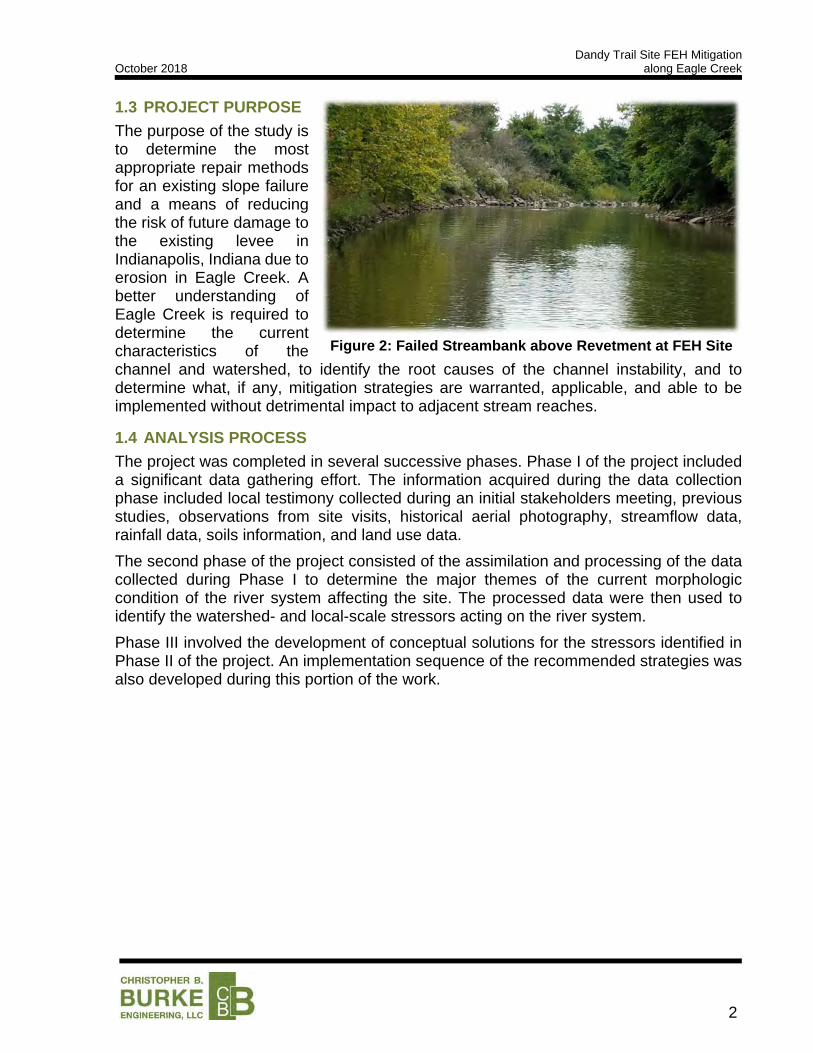
1.3 PROJECT PURPOSE
The purpose of the study is to determine the most appropriate repair methods for an existing slope failure and a means of reducing the risk of future damage to the existing levee in Indianapolis, Indiana due to erosion in Eagle Creek. A better understanding of Eagle Creek is required to determine the current characteristics of the channel and watershed, to identify the root causes of the channel instability, and to determine what, if any, mitigation strategies are warranted, applicable, and able to be implemented without detrimental impact to adjacent stream reaches.
1.4 ANALYSIS PROCESS
The project was completed in several successive phases. Phase I of the project included a significant data gathering effort. The information acquired during the data collection phase included local testimony collected during an initial stakeholders meeting, previous studies, observations from site visits, historical aerial photography, streamflow data, rainfall data, soils information, and land use data.
The second phase of the project consisted of the assimilation and processing of the data collected during Phase I to determine the major themes of the current morphologic condition of the river system affecting the site. The processed data were then used to identify the watershed- and local-scale stressors acting on the river system.
Phase III involved the development of conceptual solutions for the stressors identified in Phase II of the project. An implementation sequence of the recommended strategies was also developed during this portion of the work.
Figure 2: Failed Streambank above Revetment at FEH Site

Dandy Trail Site FEH Mitigation October 2018 along Eagle Creek
3
DATA GATHERING
Existing data and previous studies, where available, were used as supporting information for the FEH mitigation study. Additional data and observations were collected to provide a more comprehensive understanding of the physical processes at work within the river system. The following sections detail the origin and use of existing datasets and applicable previous studies, as well as the type and extent of additional information gathered.
2.1 SOURCES OF DATA
Topography Data
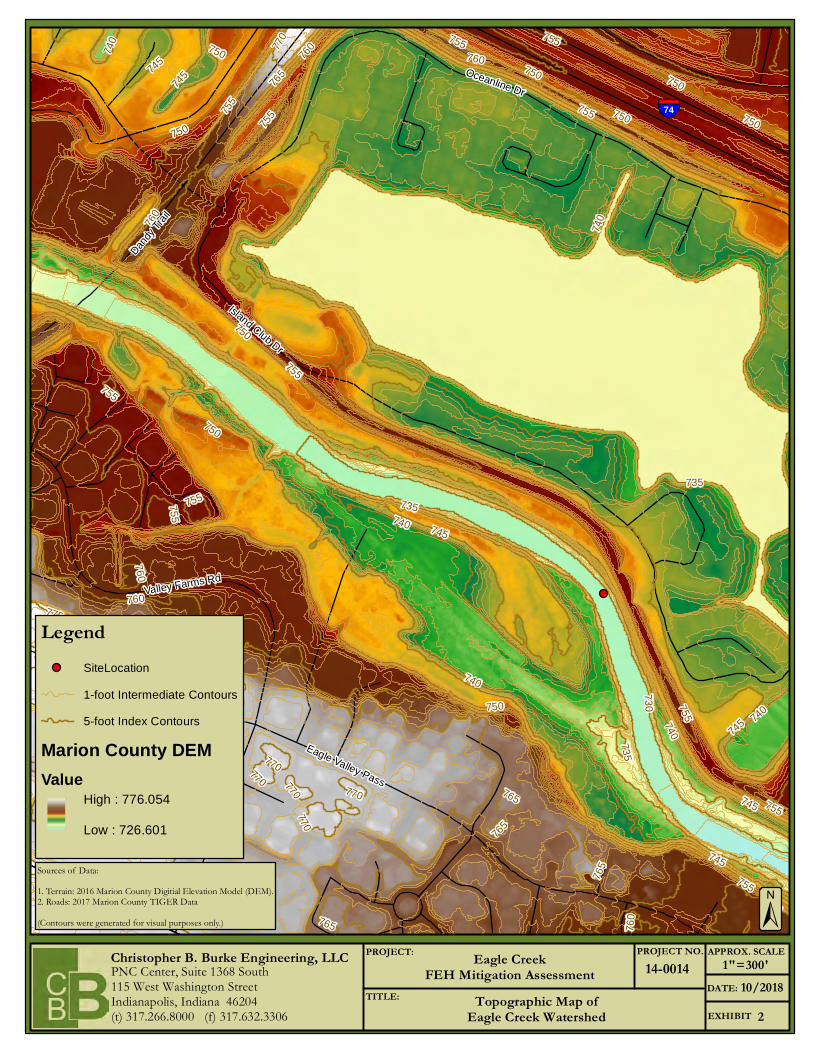
The analysis of the Eagle Creek corridor and watershed required detailed topographic information for various calculations. The 2011 IndianaMap Digital Elevation Model (DEM) was used as the source of topographic data for bankfull width approximation, floodplain connectivity considerations, and as the terrain source for a two-dimensional hydraulic model. The IndianaMap DEM covers the entire Eagle Creek Watershed with a 5-foot cell resolution, which is sufficient for producing 1-foot contours. A limited site survey was completed by SJCA on September 6, 2018 to provide more accurate topographic data of the FEH site, support the determination of the channel classification, and confirm the accuracy of the 2011 DEM. A topographic map of the Eagle Creek Watershed is provided in Exhibit 2.
Streamflow Data
Streamflow information served as a critical component to the hydrologic analysis completed as a part of this study. All streamflow information was obtained from the United States Geological Survey’s (USGS) online portal.
Aerial Photography
Aerial photography of the Eagle Creek Watershed was obtained from multiple sources. The primary source of aerial photography information was the 2011 IndianaMap Orthophotography.
Dandy Trail Site FEH Mitigation October 2018 along Eagle Creek
4
2.2 PREVIOUS STUDIES
The review of previous studies in the Eagle Creek Watershed was limited to hydrologic and hydraulic analyses, as well as a small number of other reports of significance to fluvial stability and flooding considerations.
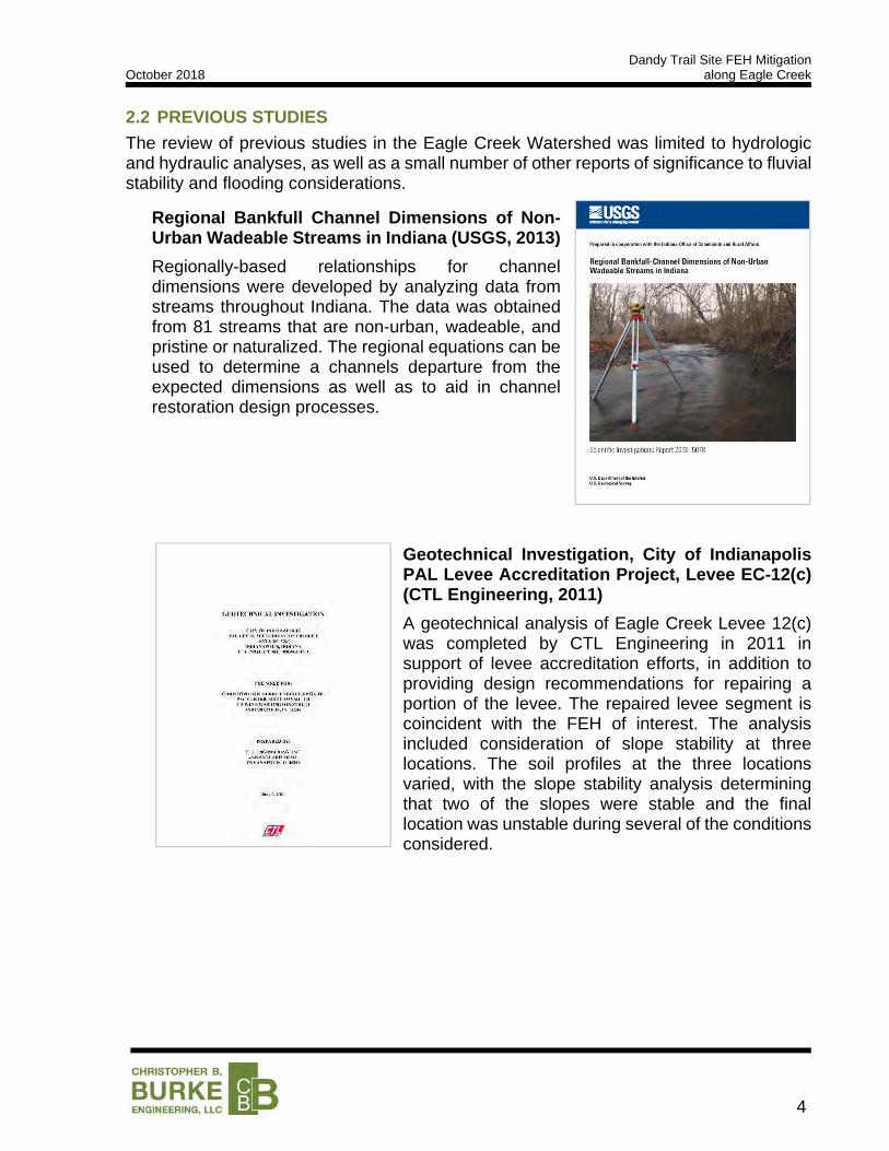
Regional Bankfull Channel Dimensions of Non-Urban Wadeable Streams in Indiana (USGS, 2013)
Regionally-based relationships for channel dimensions were developed by analyzing data from streams throughout Indiana. The data was obtained from 81 streams that are non-urban, wadeable, and pristine or naturalized. The regional equations can be used to determine a channels departure from the expected dimensions as well as to aid in channel restoration design processes.
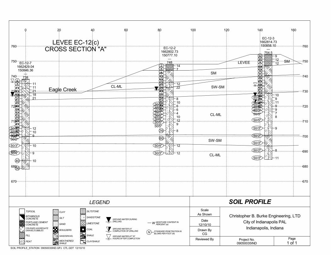
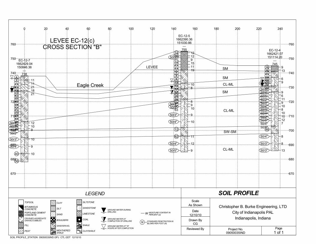
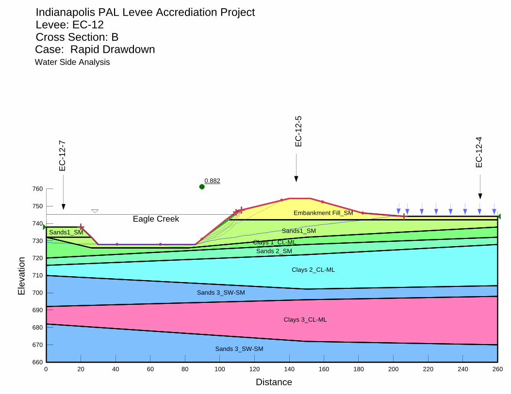
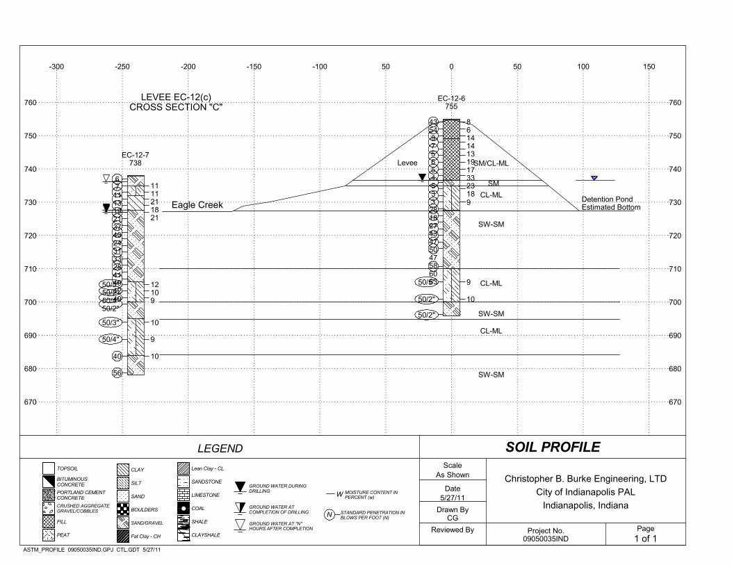
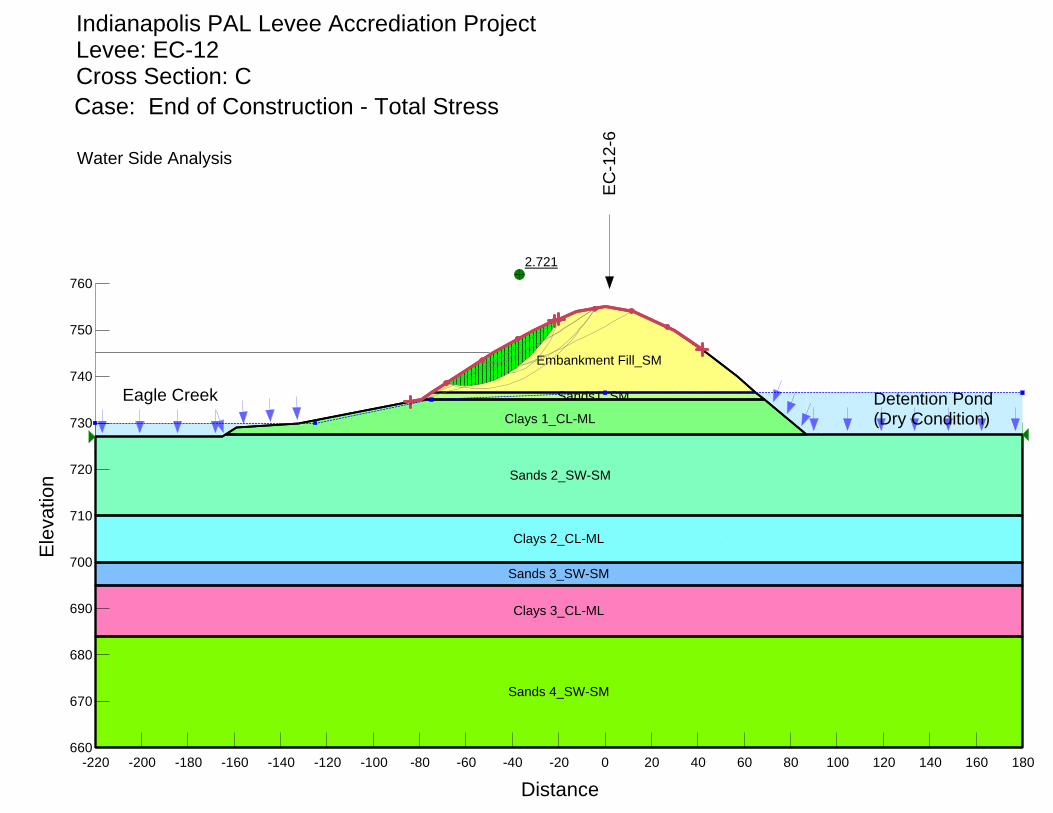
Geotechnical Investigation, City of Indianapolis PAL Levee Accreditation Project, Levee EC-12(c) (CTL Engineering, 2011)
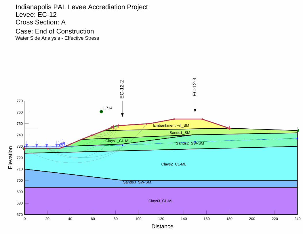
A geotechnical analysis of Eagle Creek Levee 12(c) was completed by CTL Engineering in 2011 in support of levee accreditation efforts, in addition to providing design recommendations for repairing a portion of the levee. The repaired levee segment is coincident with the FEH of interest. The analysis included consideration of slope stability at three locations. The soil profiles at the three locations varied, with the slope stability analysis determining that two of the slopes were stable and the final location was unstable during several of the conditions considered.
Dandy Trail Site FEH Mitigation October 2018 along Eagle Creek
5
FEH MITIGATION STUDY
The FEH mitigation study included consideration of the findings of previous studies, an extensive site investigation, and the contributing watershed area to the main stem of Eagle Creek. The FEH mitigation study was broken into three major categories of observations and analysis, including site assessment, watershed-scale assessment, and reach-scale assessment. The following paragraphs provide an overview of each component of the FEH mitigation study.
3.1 IDENTIFICATION OF ASSESSMENT REACH
The preliminary identification of an assessment reach is necessary to determine the extent of the stream that will be evaluated during the site assessment, to establish the portion of the overall watershed that should be considered during the watershed-scale assessment, and to provide an initial estimate of the extent of the reach-scale assessment.
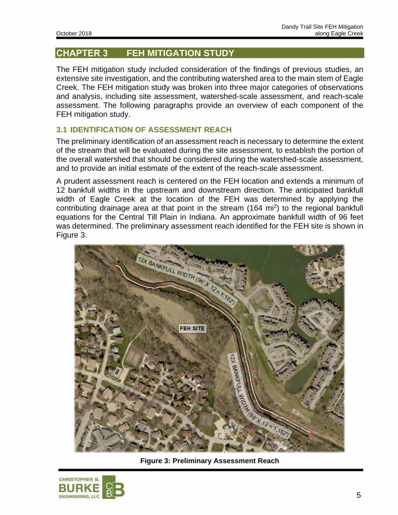
A prudent assessment reach is centered on the FEH location and extends a minimum of 12 bankfull widths in the upstream and downstream direction. The anticipated bankfull width of Eagle Creek at the location of the FEH was determined by applying the contributing drainage area at that point in the stream (164 mi2) to the regional bankfull equations for the Central Till Plain in Indiana. An approximate bankfull width of 96 feet was determined. The preliminary assessment reach identified for the FEH site is shown in Figure 3.
Figure 3: Preliminary Assessment Reach

Dandy Trail Site FEH Mitigation October 2018 along Eagle Creek
6
3.2 SITE ASSESSMENT
A site visit was conducted on September 6, 2018 to observe the river corridor along the preliminary assessment reach to determine the characteristics of the channel and to help identify the physical processes occurring in the channel. The site observations focused on measuring key dimensions of the channel and locating signs of morphological change, or changes in the channel, such as scoured and/or failed streambanks, significant upland erosion, and sediment deposition. A significant amount of riprap armoring was noted along the lower portion of the streambank.
Observations and representative measurements were made to allow for the assessment reach to be classified and to provide information that can be evaluated to determine if the channel should be expected to be relatively stable or unstable. Photographs taken during the site assessment are provided in Appendix 1.
Downstream of the dam, Eagle Creek is a B4c stream according to Rosgen Classification of Natural Rivers based on the field measurements. A B4c stream is a moderately entrenched stream with moderate sinuosity, gentle slope, and gravel streambed. A copy of the field measurements and stream classification form is provided in Appendix 2.
3.3 WATERSHED-SCALE ASSESSMENT
Typically, an evaluation of the contributing watershed would be necessary to determine if there are systemic issues contributing to the instability noted at the FEH site. The fact that the FEH site exists downstream of Eagle Creek Dam indicates that systemic issues exist, as the dam disrupts the natural conveyance of flow and sediment. Rather than seeking to determine the potential causes of observed changes at the site, the watershed assessment was used to quickly evaluate the severity of the systemic issues caused by the dam and to identify the infrastructure at risk from the anticipated fluvial instability.
Artificial Hydrology and Sediment Barrier caused by Eagle Creek Dam Eagle Creek Dam effectively controls the hydrology for the assessment reach. The dam operates based on standard procedures that contain a limited number of possible outflow ‘settings’. These discrete ‘settings’ do not allow the downstream channel to experience the continuous, natural, rainfall-driven inputs from the watershed. The downstream channel is subjected to abrupt changes in flow; the flows do not meaningfully increase or decrease, but rather create elongated flow ‘stair-steps’. This artificial hydrology subjects the channel to prolonged erosive flows that would naturally tend to destabilize a channel.
Figure 4: Controlled vs. Natural Flow
0
500
1,000
1,500
2,000
2,500
3,000
10/31/2018 11/2/2018 11/4/2018 11/6/2018 11/8/2018 11/10/2018
Flo
w R
ate
(cfs
)
Date (mm/dd/yyyy)
Controlled Flow from Eagle Ck Dam Natural Flow
Dandy Trail Site FEH Mitigation October 2018 along Eagle Creek
7
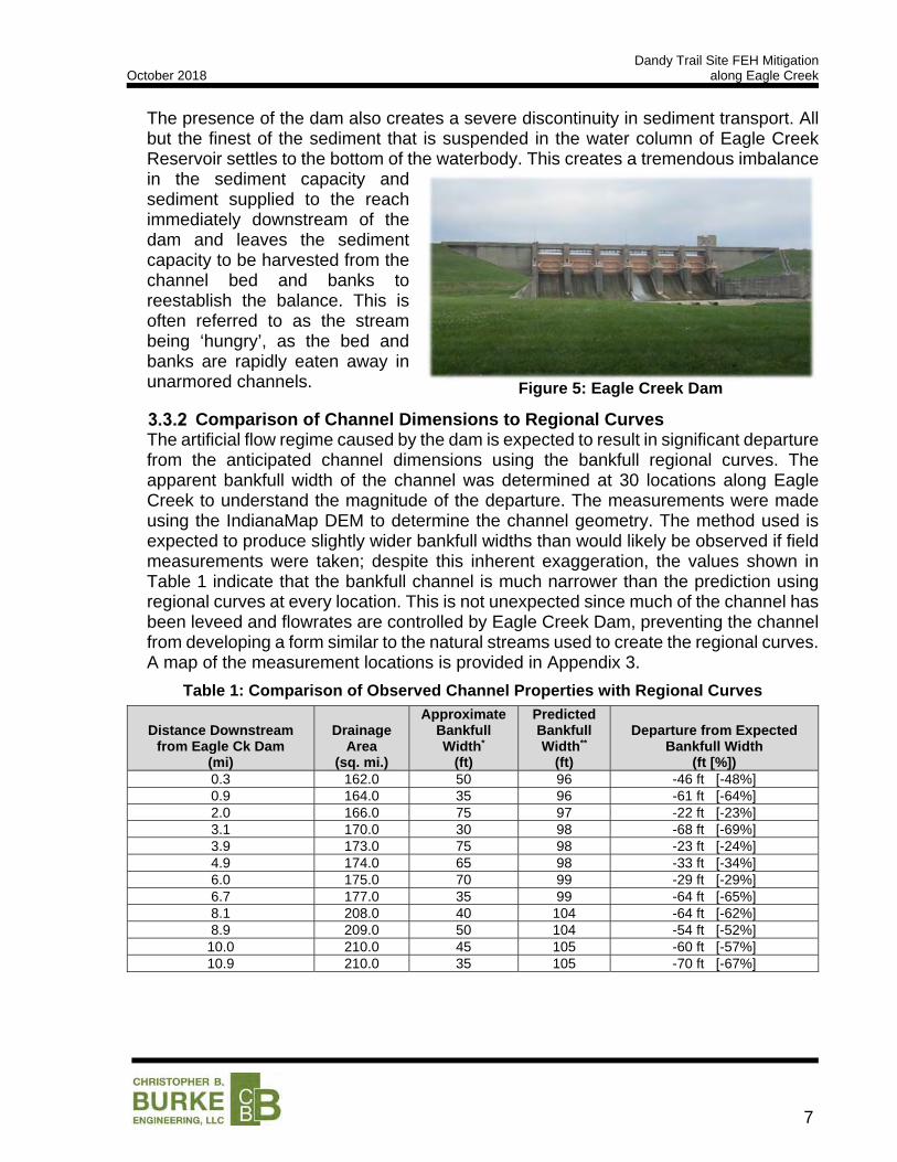
The presence of the dam also creates a severe discontinuity in sediment transport. All but the finest of the sediment that is suspended in the water column of Eagle Creek Reservoir settles to the bottom of the waterbody. This creates a tremendous imbalance in the sediment capacity and sediment supplied to the reach immediately downstream of the dam and leaves the sediment capacity to be harvested from the channel bed and banks to reestablish the balance. This is often referred to as the stream being ‘hungry’, as the bed and banks are rapidly eaten away in unarmored channels.
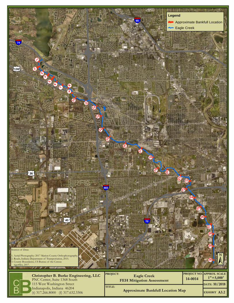
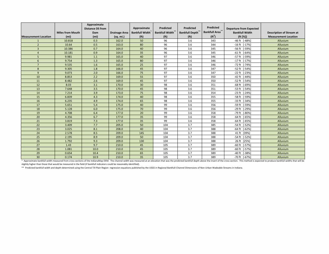
Comparison of Channel Dimensions to Regional Curves The artificial flow regime caused by the dam is expected to result in significant departure from the anticipated channel dimensions using the bankfull regional curves. The apparent bankfull width of the channel was determined at 30 locations along Eagle Creek to understand the magnitude of the departure. The measurements were made using the IndianaMap DEM to determine the channel geometry. The method used is expected to produce slightly wider bankfull widths than would likely be observed if field measurements were taken; despite this inherent exaggeration, the values shown in Table 1 indicate that the bankfull channel is much narrower than the prediction using regional curves at every location. This is not unexpected since much of the channel has been leveed and flowrates are controlled by Eagle Creek Dam, preventing the channel from developing a form similar to the natural streams used to create the regional curves. A map of the measurement locations is provided in Appendix 3.
Table 1: Comparison of Observed Channel Properties with Regional Curves
Distance Downstream from Eagle Ck Dam
(mi)
Drainage Area
(sq. mi.)
ApproximateBankfull Width*
(ft)
Predicted Bankfull Width**
(ft)
Departure from Expected Bankfull Width
(ft [%])
0.3 162.0 50 96 -46 ft [-48%] 0.9 164.0 35 96 -61 ft [-64%] 2.0 166.0 75 97 -22 ft [-23%] 3.1 170.0 30 98 -68 ft [-69%] 3.9 173.0 75 98 -23 ft [-24%] 4.9 174.0 65 98 -33 ft [-34%] 6.0 175.0 70 99 -29 ft [-29%] 6.7 177.0 35 99 -64 ft [-65%] 8.1 208.0 40 104 -64 ft [-62%] 8.9 209.0 50 104 -54 ft [-52%]
10.0 210.0 45 105 -60 ft [-57%] 10.9 210.0 35 105 -70 ft [-67%]
Figure 5: Eagle Creek Dam
Dandy Trail Site FEH Mitigation October 2018 along Eagle Creek
8
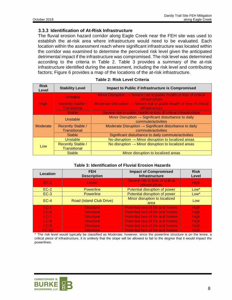
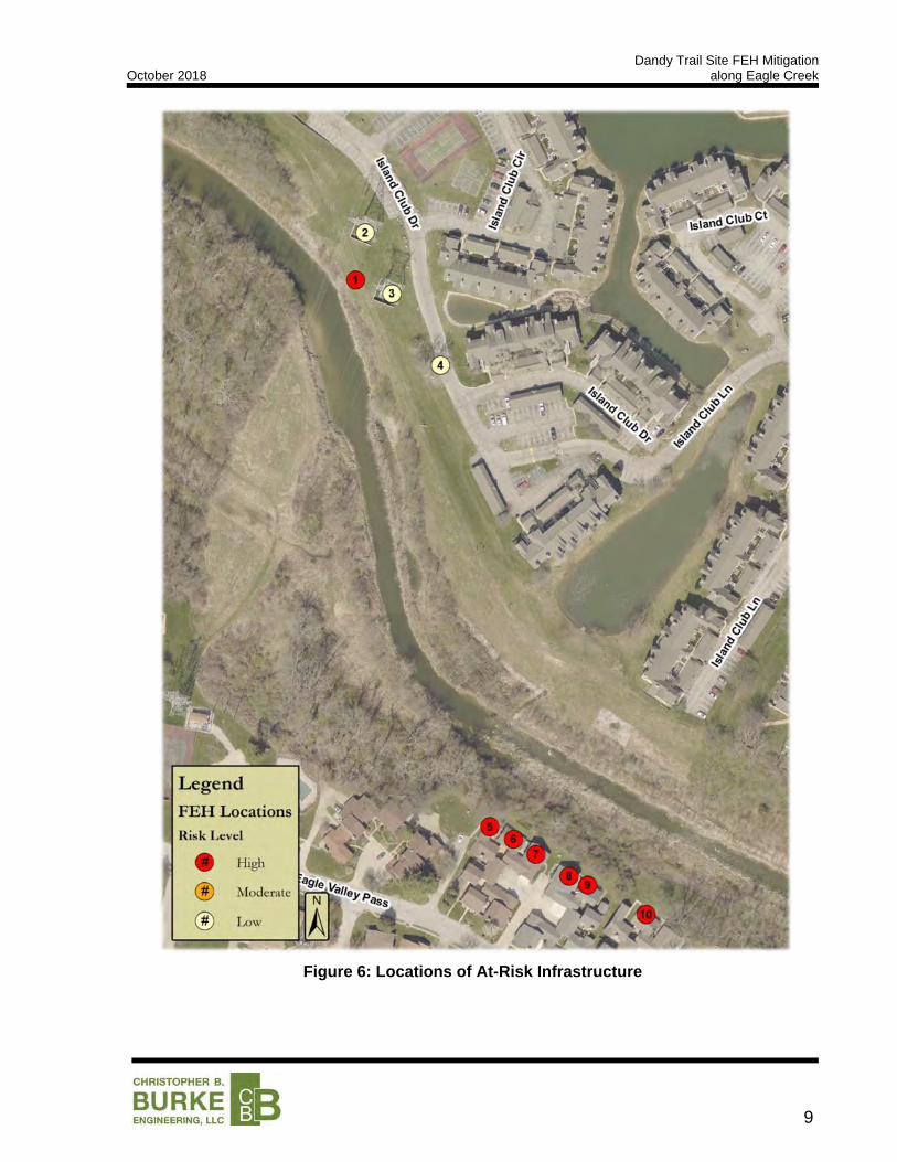
Identification of At-Risk Infrastructure The fluvial erosion hazard corridor along Eagle Creek near the FEH site was used to establish the at-risk area where infrastructure would need to be evaluated. Each location within the assessment reach where significant infrastructure was located within the corridor was examined to determine the perceived risk level given the anticipated detrimental impact if the infrastructure was compromised. The risk level was determined according to the criteria in Table 2. Table 3 provides a summary of the at-risk infrastructure identified during the assessment, including the risk level and contributing factors; Figure 6 provides a map of the locations of the at-risk infrastructure.
Table 2: Risk Level Criteria
Risk Level
Stability Level Impact to Public if Infrastructure is Compromised
High
Unstable Minor Disruption → Severe risk to public health or loss of critical
infrastructureRecently Stable /
Transitional Moderate Disruption → Severe risk to public health or loss of critical
infrastructureStable Severe risk to public health or loss of critical infrastructure
Moderate
Unstable Minor Disruption → Significant disturbance to daily
commute/activities Recently Stable /
Transitional Moderate Disruption → Significant disturbance to daily
commute/activities Stable Significant disturbance to daily commute/activities
Low
Unstable No disruption → Minor disruption to localized areasRecently Stable /
Transitional No disruption → Minor disruption to localized areas
Stable Minor disruption to localized areas
Table 3: Identification of Fluvial Erosion Hazards
Location FEH
DescriptionImpact of Compromised
Infrastructure Risk Level
EC-1 Levee Severe risk to loss of critical
infrastructureHigh
EC-2 Powerline Potential disruption of power Low*EC-3 Powerline Potential disruption of power Low*
EC-4 Road (Island Club Drive) Minor disruption to localized
areaLow
EC-5 Structure Potential loss of life and homes HighEC-6 Structure Potential loss of life and homes HighEC-7 Structure Potential loss of life and homes HighEC-8 Structure Potential loss of life and homes HighEC-9 Structure Potential loss of life and homes HighEC-10 Structure Potential loss of life and homes High
* The risk level would typically be classified as Moderate; however, since the powerline structure is on the levee, a critical piece of infrastructure, it is unlikely that the slope will be allowed to fail to the degree that it would impact the powerlines.
Dandy Trail Site FEH Mitigation October 2018 along Eagle Creek
9
Figure 6: Locations of At-Risk Infrastructure
Dandy Trail Site FEH Mitigation October 2018 along Eagle Creek
10
3.4 REACH-SCALE ASSESSMENT
A more detailed evaluation of the assessment reach was completed to quantify the parameters needed to develop conceptual active management solutions. The analyses were also used to further improve the understanding of the local system. The following paragraphs summarize the additional analyses completed for the reach-scale assessment.
Refined Assessment Reach The preliminary assessment reach extent was evaluated to determine if the detailed analyses should cover the entirety of the reach or if analysis and evaluation efforts could be limited to a smaller area. The full extent of the preliminary reach was determined to be necessary as a result of the overflow path in the right overbank area. Some of the analyses completed considered areas beyond the refined assessment reach but did so only to reduce the influence of assumptions and selected boundary conditions for the hydraulic model.
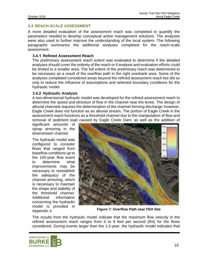
Hydraulic Analysis A two-dimensional hydraulic model was developed for the refined assessment reach to determine the speed and direction of flow in the channel near the levee. The design of alluvial channels requires the determination of the channel forming discharge; however, Eagle Creek does not function as an alluvial stream. The portion of Eagle Creek in the assessment reach functions as a threshold channel due to the manipulation of flow and removal of sediment load caused by Eagle Creek Dam, as well as the addition of significant amounts of riprap armoring in the downstream channel.
The hydraulic model was configured to consider flows that ranged from baseflow conditions up to the 100-year flow event to determine what improvements may be necessary to reestablish the adequacy of the channel armoring, which is necessary to maintain the shape and stability of the threshold channel. Additional information concerning the hydraulic model is provided in Appendix 4.
The results from the hydraulic model indicate that the maximum flow velocity in the refined assessment reach ranges from 5 to 9 feet per second (ft/s) for the flows considered. During events larger than the 1.5-year, the hydraulic model indicates that
Figure 7: Overflow Path near FEH Site

Dandy Trail Site FEH Mitigation October 2018 along Eagle Creek
11
the flow leaves the channel just upstream of the site of interest. The velocities through the overflow path range from 4 to 7 ft/s for events up to the 100-year flow. Flow moving as swiftly as the flow in both locations is capable of causing bank scour and preventing the establishment of vegetation. Bank scour and a lack of vegetation can initiate bank instability.
It should be noted that the maximum velocity in the main channel does not occur during the most extreme event. The highest velocity occurs in the channel just prior to when the overflow path is activated. This provides a clear example of the benefit that a floodplain can provide in terms of energy dissipation. Unfortunately, the floodplain at this location in Eagle Creek is not attached to the channel at an appropriate depth, which allows erosive flows to occur prior to the energy-dissipating activation of the overflow path.
Scour Evaluation The results of the hydraulic model were used to compute general scour and bend scour at the FEH site. The general scour calculations were completed using the Blodgett and Pemberton and Lara methods. The results of the analyses show that scour depths near the FEH site are expected to range from 2 to 9 feet for general scour. Long-term channel degradation is not accounted for in the above-mentioned scour depths. Scour calculations are provided in Appendix 4.
Slope Stability Analysis The 2011 CTL Geotechnical Investigation included a slope stability analysis of three locations along Levee EC-12(c). The soil profiles for each location varied; however, the calculated factors of safety are well-correlated with the slope of the bank. The results of the analysis suggest that slopes 2.5 feet horizontal to 1 foot vertical (2.5H:1V) or flatter are acceptably stable and slopes that are 1.2H:1V or steeper are unstable. The low factor of safety (0.882) for the 1.2H:1V slope suggests that slopes slightly flatter than 1.2H:1V are also unstable. It should be noted that the unstable location from the CTL analysis corresponds to the FEH of interest.
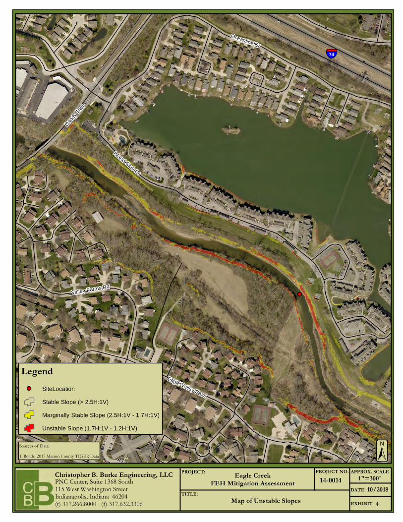
An analysis of the land slope within the refined assessment reach was evaluated to determine the location and extent of banks that have either failed or should be considered unstable. Slopes of 2.5H:1V and flatter were considered stable, slopes between 2.5H:1V and 1.7H:1V were considered marginally stable, and slopes steeper than 1.7H:1V were considered unstable. Exhibit 3 provides a map of the estimated slope stability proximate to the channel. A significant portion of the channel banks within the project reach are expected to be marginally stable; approximately 500 feet of the channel bank at the FEH location has either failed or is expected to be unstable.

Dandy Trail Site FEH Mitigation October 2018 along Eagle Creek
12
3.5 KEY FINDINGS OF FEH MITIGATION STUDY
The most significant factors affecting the stability of the channel through the assessment reach identified during the FEH mitigation study are described in the following paragraphs. All of the stressors identified have interplay with at least one of the other stressors, creating a compounding effect that reduces the overall stability of the river.
Eagle Creek Dam & Threshold Channel Conditions
As discussed in Section 3.3.1, Eagle Creek Dam prevents the natural delivery of flow and sediment to the assessment reach. The operation of the dam results in elevated, elongated, and ‘clear water’ flows that result in the stream being unstable without armoring.
Much of the channel has been armored with riprap. The areas where the riprap appears to be of inadequate size or depth have eroded, and in many cases become unstable.
Channel Incision & Inadequate Floodplain Connectivity
The human-imposed narrowness of the main channel confines the flow, preventing meaningful floodplain storage at or above a bankfull event. In healthy streams, the channel is well-connected to a substantial floodplain that helps to store excess flow and sediment, as well as to reduce the overall erosive energy in the flow.

Dandy Trail Site FEH Mitigation October 2018 along Eagle Creek
13
STAKEHOLDER INPUT AND MITIGATION OBJECTIVES
The identification of the overall mitigation objectives is critical to the development of mitigation strategies and the success of the project. Establishing a clear decision-making process, evaluating the impairments to be addressed, and considering the potential improvements using a merit-based system is imperative to a prudent design. It is also important to identify what will constitute ‘project success’. These factors should be considered by appropriate stakeholders.
4.1 DECISION MAKING PROCESS
The decision to proceed with a design of mitigation features will ultimately lie with the City of Indianapolis. The conceptual improvements identified later in Chapters 5 and 6 were determined by the designer using the objectives noted below with consideration of the impairments to be mitigated and the likelihood of mitigation success.
4.2 MITIGATION OBJECTIVES
Conversations with City officials revealed concern over the long-term viability of the levee adjacent to Eagle Creek due to observations of streambank erosion. The following objectives were implied:
1. Prevent the stream from compromising the toe of the levee and minimize the long-term FEH risk
2. Low maintenance need for improvements 3. Cost efficient construction
Impairments to be Mitigated The FEH site has several impairments that must be considered to meet the mitigation objectives. The impairments are both local instabilities and systemic issues affecting the channel downstream of the dam. The following issues must be addressed by the design:
1. High flow velocities and scour through the assessment reach
2. Bank instability at the site, largely attributable to over-steepened slopes
3. Prolonged erosive flow rates due to increased runoff volume and artificial hydrology
Functional Lift The relatively small extent of the FEH of interest and the limited scope of the objectives for the project reduce the potential for providing function lift to the stream reach.
The severe systemic issues imposed by Eagle Creek Reservoir and Dam cannot be alleviated without removal of the facility and the reestablishment of a natural river corridor, both of which are impracticable. Without significant naturalization, localized FEH mitigation measures should not be expected to provide significant functional lift to the overall stream.
Dandy Trail Site FEH Mitigation October 2018 along Eagle Creek
14
4.3 PRIORITIZED MITIGATION OBJECTIVES & PERFORMANCE METRICS
The mitigation objectives identified in Section 4.2 were provided in the order of priority that was understood from conversations with the City of Indianapolis. The specific mitigation objectives have been expanded in the list below and are accompanied by designer-specified performance objectives intended to achieve the stated objectives:
1. Prevent the stream from compromising the toe of the levee and minimize the long-term FEH risk:
This mitigation objective will require active management strategies to effectively stop erosion in the vicinity of the at-risk levee. Prudent performance metrics for the improvements near the area of interest include:
A. Flow velocity during the 100-year event must be below the acceptable performance threshold of the surface cover/protection to prevent erosion during all but the most extreme of flow events.
B. Flow vectors during the full range of flow events should be well aligned with the surface contouring inundated by and adjacent to the flow.
C. Protect against long-term degradation. D. Mitigation measures implemented in and adjacent to the stream should
consider the potential for the peak annual flow rate to continue to rise for the engineering life-span of the project, although expected at a lower rate of increase compared with an unregulated flow stream.
2. Low maintenance need for improvements
Low maintenance requirements hinge on the types of improvements designed and the types of materials selected. Maintenance need is heavily dependent on uncontrolled variables (e.g. severity and frequency of flooding, debris strikes, etc). As a result, performance metrics are limited to anticipated outcomes rather than results of detailed analyses:
A. Maintenance activities should be required no more frequently than once, annually.
B. Material selections should have a long (20+ year) life-span to reduce or prevent the need to replace components of the project.
3. Cost efficient construction
Minimizing the project implementation cost requires evaluation of materials and active management stabilization methods used. Though the overall cost of the improvements cannot be accurately predicted or determined prior to the selection of active management treatments, generalized goals can be established:
A. A high project cost is anticipated due to the presence of the levee. B. The complexity of the design should be minimized to reduce installation
costs and materials should be locally available and cost efficient.
Dandy Trail Site FEH Mitigation October 2018 along Eagle Creek
15
PASSIVE MANAGEMENT CONSIDERATIONS
Passive management strategies are most effective for addressing systemic issues that are watershed-based, or site-specific issues for a location that does not have a large contributing drainage area. That would seem to suggest that the use of passive management strategies is ideal for the mitigation of the FEH of interest; however, the majority of the systemic issues arise from the presence of Eagle Creek Dam. Furthermore, the benefit of watershed-scale measures will likely be dampened downstream of the Eagle Creek Reservoir. As a result, passive measures are not considered a viable solution for the FEH site.
Dandy Trail Site FEH Mitigation October 2018 along Eagle Creek
16
ACTIVE RIVER MANAGEMENT ANALYSIS
Active river management includes modifications to the stream corridor that directly combat or eliminate the instabilities that are present. Various types of active management strategies can be combined to create robust improvements to specific portions of the channel or the entire channel through a given reach. Active river management methods must address both vertical and lateral instability to be effective.
6.1 VERTICAL STABILITY CONSIDERATIONS
Improvements to the FEH mitigation site will need to address two potential sources of vertical instability: scour along the toe of the bank during significant flow events and the potential for long-term degradation or head-cutting caused by the imbalance in sediment supply and capacity.
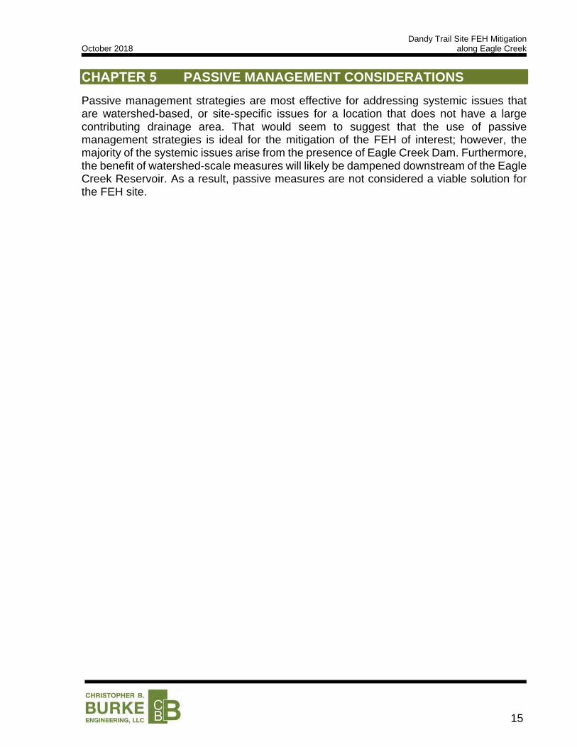
Toe protection measures are typically necessary for FEH mitigation sites that have vertical or horizontal stability issues due to the fact that a bank is not likely to remain stable if the toe is eroded; this is particularly true for the FEH site due to the slope stability issues already present. Toe protection usually comes in the form of large stone, concrete, or wooden revetment that is designed to be immobile, even during high flow events; sheet piling is sometimes used when the site is particularly confined. An example of riprap toe protection is shown in Figure 8. There is currently toe protection material in place at the site; however, the size, extent, and location may not be ideal.
Grade control structures and/or bed armoring are often used to prevent the process of channel degradation, or the gradual lowering of the channel invert elevation due to erosion downstream propagating upstream. Grade control structures can be made of large, immobile stone, concrete, or sheet piling and span the width of the channel to stop the upstream migration of a headcut.
6.2 LATERAL STABILITY CONSIDERATIONS
Failed, over-steepened, and undermined banks are unstable due to an inability to support the weight of the soil forming the bank. Where banks suffer from this type of geotechnical instability, a simple and cost-effective means of correcting the issue is to reduce the slope to a more stable angle, typically in the range of 3-feet horizontal to 1-foot vertical (3H:1V), or flatter.
Figure 8: Toe Protection Measures
Dandy Trail Site FEH Mitigation October 2018 along Eagle Creek
17
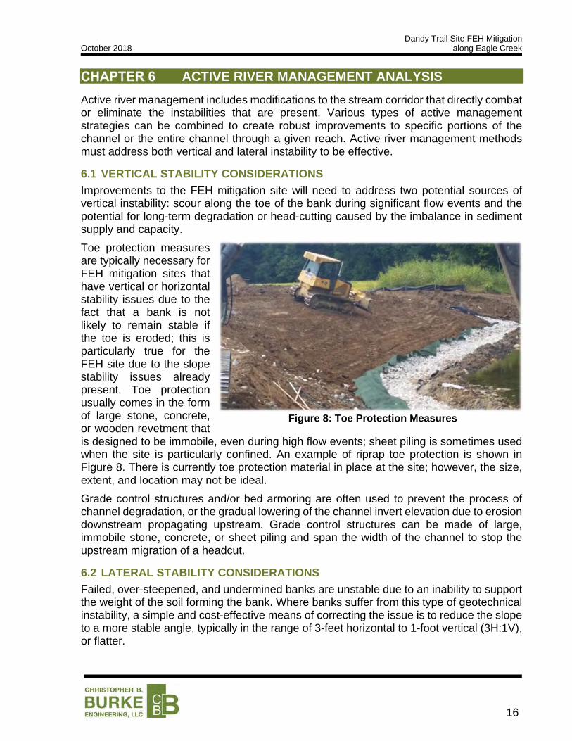
Natural, healthy streams in Indiana typically meander and gradually move back and forth across their floodplain. In certain situations, such as this one, allowing the movement of the stream can endanger critical infrastructure. Utilizing an armoring system on the channel banks can help to prevent the natural erosion processes that allow the channel to move or change its shape in meaningful ways. Channel armoring is accomplished by installing a system that can withstand the flow velocity in the channel with negligible loss of bank and bed material over time; riprap, turf reinforcement mats, soil cement, etc. are examples of common armoring systems.
6.3 PROPOSED MITIGATION MEASURES
The type of mitigation techniques used to improve the stability of a stream is dependent on the type of instability present in the channel. The reach of Eagle Creek exhibits various forms of instability, including bank scour, potential vertical instability, and minor lateral migration. The proposed mitigation techniques and the portions of the stream to which the strategies are applicable are discussed below.
Evaluation of and Selection of Improvement Alternatives There are different treatment methods available to address the different types of instability presented at the mitigation site. For vertical instability, treatments that provide toe protection are the most applicable. These treatments include toe wood, interlocking concrete jacks, and gabion baskets. For lateral instability, treatments that provide channel armoring are the most applicable. These treatments include gabion baskets, soil lifts with live stakes, and erosion control blanket systems. Each of the three types of toe protection were considered in conjunction with soil lifts, live stakes, and erosion control blankets.
A triple bottom line comparison was completed for the three channel improvement alternatives to evaluate the economic costs, social benefits, and environmental benefits. A summary of the triple bottom line comparison is provided in Table 4. The complete triple bottom line decision matrix is included in Appendix 5.
Table 4: Triple Bottom Line Comparison of Improvement Alternatives
Improvement Alternative Economic
Score Social Score
Environmental Score
Total Score
Toe Wood 2.8 2.0 2.7 7.5
Interlocking Concrete Jacks 2.5 2.0 3.1 7.6
Gabion Wall 2.3 2.0 3.4 7.7
Figure 9: Armored Channel in Indianapolis, IN

Dandy Trail Site FEH Mitigation October 2018 along Eagle Creek
18
Toe wood had the highest economic score because it was the least expensive and has moderate lifecycle cost in this application. Gabion baskets were the most expensive and have a moderate lifecycle cost. The interlocking concrete jacks have a low to moderate lifecycle cost but have a higher installation cost than toe wood.
All three treatment methods have the same potential social benefits score as they all provide a relatively similar level of service. The benefit of maintaining the integrity of the levee extends to a large number of properties and as a result provides a moderate to high level of benefit to public safety. However, none of the treatment methods are capable of improving flooding or drainage issues due to the extreme confinement of the channel. The project will also afford no meaningful improvement to quality of life.
The differentiating factor in the environmental scores relates to the permitability of the treatment methods, particularly with regard to meeting requirements for a certified levee. Toe wood is typically a very high performing treatment method with regard to environmental benefit; however, the permitability of toe wood as a part of a certified levee is doubtful. Adequately consolidating clayey material around the structure will likely be impossible and the infill materials will allow for a preferential seepage path to develop. These concerns caused toe wood to have the lowest environmental score. All the protection types provided a robust level of protection but did little to restore or protect the floodplain function of the stream because the limitations of the project resulting from the upstream dam and confined stream. The certainty in the quality of material consolidation and ease of installation is highest for gabion baskets, which resulted in the highest score due to the ease of permitability.
Description of Improvements The proposed improvements include the use of riprap to reinforce the toe of the levee and reducing the over-steepened section of the streambank. Erosion control blankets will be used to prevent erosion above the riprap toe protection.
A schematic layout of the potential improvements is provided in Exhibit 4. As can be seen in the exhibit, significant impacts to the stream are required to install the treatments. It is anticipated that armoring the streambank would require the acquisition of the following environmental permits, at a minimum:
IDNR Construction in a Floodway
IDEM Section 401 Water Quality Certification
USACE Section 404 Dredge & Fill Permit
IDEM Rule 5 Permit
The recommended bank armoring detail, or any other stabilization method, should not be used indiscriminately along the channel to ‘fix’ the banks. The installation of bank armoring can result in increased erosion and instability downstream of the project that impacts adjacent properties. Strategic integration of the improvements into the stream corridor is paramount to project success.
The cost of designing, permitting, and constructing these improvements is expected to be approximately $374,000. A detailed breakdown of the anticipated project cost is provided in Appendix 5.
Dandy Trail Site FEH Mitigation October 2018 along Eagle Creek
19
Anticipated Performance The improvements are expected the stabilize the streambank through the FEH site. Reinforcing the toe of the bank, adjusting the bank to provide a stable slope, and protecting the levee with erosion control blanket should provide sufficient resistance to erosion and prevent further instability. An evaluation of the mitigation objectives using the previously identified performance metrics is as follows:
1. Prevent the stream from compromising the toe of the levee and minimize the long-term FEH risk:
The anticipated maximum flow velocity is 9 ft/s in the channel and 7 ft/s in the overflow path. Class 1 riprap will be necessary to adequately armor the toe given the high channel velocity. Most erosion control blanket systems have a performance threshold of up to 9 ft/s in an unvegetated state. This performance metric is met, as both erosion prevention systems have adequate erosion resistance during the 100-year event.
The adjustment of the slope of the left channel bank helps to improve the direction of the flow vectors to be more well-aligned with the bank during the full range of flow events.
The FEH site is protected against long-term degradation by installing the toe protection measures to an adequate depth to resist scour.
2. Low maintenance need for improvements
Utilizing various forms of riprap protection at and below the ordinary high-water mark will minimize the need for maintenance at the toe of the slope. The use of gabion baskets does require monitoring and maintenance when the baskets begin to break down due to debris strikes or corrosion.
The use of mitigation measures that are only vegetative on the upper portion of the slope reduces the difficulty of the required maintenance activities; in fact, the grass species used in conjunction with the erosion control blankets can be selected such that they do not need to be mowed to maintain a vigorous stand.
The use of non-degradable erosion control blankets and vegetation as reinforcement reduce the likelihood that the system would need to be augmented or replaced.
3. Cost efficient construction
The overall project cost for the improvements is anticipated to be approximately $262,000. The total length of stabilized streambank is 265 feet, resulting in a unit cost of $600 per foot. The cost per foot is slightly inflated by the additional grading area not included in the length of stabilized streambank.
The proposed methods are common construction methods, cost efficient given the presence of the levee, and the materials are locally available.
Dandy Trail Site FEH Mitigation October 2018 along Eagle Creek
20
RECOMMENDATIONS
The results of the stream assessment described in Section 3.0 and the key factors influencing the stability of Eagle Creek described in Section 3.5 suggest that the issues are likely to persist and cannot be solved by correcting a problem in a specific location. However, the levee serves as critical infrastructure to Indianapolis, and should therefore be protected against damage from fluvial erosion. Monitoring the channel conditions at the FEH site will be a critical component to maintaining the integrity of the FEH mitigation along the levee.
7.1 MONITORING
Once the improvements have been constructed, the condition of the reconstructed bank at the FEH site should be monitored on an annual basis, and/or after significant flooding events. If the improvements are damaged or the embankment is threatened by stream migration, remedial action should be completed as soon as possible.
7.2 IMPROVEMENT IMPLEMENTATION
Armoring approximately 265 feet of the bank at the FEH site is expected to prevent the erosion of the streambank from compromising the integrity of the levee. Reinforcing the toe of the bank, adjusting the upper portion of the bank to provide a stable slope, and protecting the upper slope with erosion control blanket should provide sufficient resistance to erosion to prevent further instability. Exhibit 4 shows a typical section of the recommended method of bank armoring. Additional methods and treatments that are applicable for bank armoring exist; however, the recommended method was selected based on limiting the risk of failure while being sensitive to overall project cost.
7.3 NEXT STEPS
The following steps are recommended to reduce the fluvial erosion hazard risk along Eagle Creek at EC-12(c):
1. Meet with CBBEL to discuss the findings and recommendations of this report.
2. Move forward with the detailed design and permitting of the proposed FEH mitigation measures for EC-12(c).
3. Establish a monitoring plan that records the location and condition of the streambank and other significant changes to the channel at the identified fluvial erosion hazard location and any additional FEH locations that may become a concern in the future.

Dandy Trail Site FEH Mitigation October 2018 along Eagle Creek
21
REFERENCES
Chow, V. T. (1959). Open-Channel Hydraulics. Caldwell: The Blackburn Press.
Leopold, L.B., Wolman, M.G., and Miller, J.P. (1964) Fluvial Processes in Geomorphology. Freeman, 522 p.
National Oceanic and Atmospheric Administration (NOAA). National Climatic Data Center (NCDC). Hourly Rainfall Data for Indianapolis International Airport. Available http://gis.ncdc.noaa.gov/map/viewer/. Accessed October 1, 2018.
Robinson, B.A., 2013, Recent (circa 1998 to 2011) channel-migration rates of selected streams in Indiana: U.S. Geological Survey, Scientific Investigations Report 2013–5168, 14 p. plus 1 app., http://pubs.usgs.gov/sir/2013/5168/.
Robinson, B.A., 2013, Regional bankfull-channel dimensions of non-urban wadeable streams in Indiana: U.S. Geological Survey, Scientific Investigations Report 2013-5078, 33 p.
Rosgen, D, L. (1996) Applied River Morphology. Wildland Hydrology, variously paged.
United States Geological Survey. Stream Gage Data for Station 03353460 Eagle Creek at Indianapolis, IN. Available http://maps.waterdata.usgs.gov/mapper. Accessed October 15, 2018.
United States Geological Survey. Stream Gage Data for Station 03353500 Eagle Creek at Indianapolis, IN. Available http://maps.waterdata.usgs.gov/mapper. Accessed October 15, 2018.

Eagle Creek October 2018 FEH Mitigation Assessment
Exhibits
Indianapolis city (balance)
Carmel
Zionsville
Avon
Westfield
Plainfield
Lebanon
Whitestown
Brownsburg
Danville
Noblesville
Speedway
Pittsboro
Beech Grove
Sheridan
Meridian HillsLizton
Clermont
Clayton
Fishers
Ulen
Crows NestRocky Ripple
Williams Creek
Wynnedale
Fishers
North Crows Nest
Boone
MarionHendricks
Hamilton
Christopher B. Burke Engineering, LLCPNC Center, Suite 1368 South115 West Washington StreetIndianapolis, Indiana 46204(t) 317.266.8000 (f) 317.632.3306
PROJECT:
TITLE:
PROJECT NO. APPROX. SCALE
EXHIBIT
DATE:
Eagle CreekFEH Mitigation Assessment
Study Area Map
14-0014
110/2018
MORGAN COUNTYMARION COUNTY
Allen
Lake
Jay
Knox
Vigo
White
Po
rte
r
Jasper
Cass
Clay
Pike
Rush
Parke
Grant
Greene
La Porte
Perry
Clark
Ripley
Noble
Gibson
We
lls
Pos
ey
Elkhart
Owen
Henry
Boone
Mia
mi
Pu
tna
m
Jackson
Dubois
Sh
elb
y
Pulaski Fulton
Marion
Wayne
Clinton
Sullivan
Ha
rrison
Benton Carroll
Da
vie
ss
Ma
rtin
Orange
Ko
sciu
sko
Mo
nro
e
Morgan
Ma
dis
on
Ne
wto
n
Marshall
Warrick
Wab
ash
Warren
Bro
wn
Franklin
Ad
am
s
Starke
Spenc
er
Decat
ur
Randolph
Lawrence
Whi
tley
Foun
tain
De Kalb
Hamilto
n
Was
hing
ton
St. Joseph
Tip
pe
can
oe
Tipton
Jenn
ings
De
law
are
He
nd
rick
s
Lagrange
Mo
ntg
om
ery
Jefferson
Steuben
Howard
Joh
nso
n
Scott
Hu
ntin
gto
n
Hancock
Crawford
Dea
rbor
n
Bartholo
mew
Fayette Un
ion
Flo
yd
Ve
rmill
ion
Switzerland
Ohio
Vanderburgh
Blackford
_̂
_̂
Coast D
rS
alt L
ake
Rd
Valle
y F
arm
s R
d
Island Club Dr
Waterfront Dr
US Hwy 136
Towpath Ln
Peb
ble Po
int D
r
Tink
ersf
ield
Ln
Island Club Ln
Eagle Valley Pass
Dandy Trl
Eddy Ct
Sunfield Ct
Stillmeadow Dr
Valley F
arm
s Ln
Island Club C
t
Va
lley
Far
ms
Ct
Valley Farms Trl
Island Club Dr
Isla
nd C
lub
Ln
±
1 " = 500 ' ±
±
As Shown
STATE MAP VICINITY MAP
STUDY AREA MAP
1 in = 58 miles 1 in = 6 miles
¬«39
¬«267
£¤40
§̈¦70_̂ §̈¦65
§̈¦465
§̈¦74
£¤36
£¤421
£¤31
745
740
735
750
755
760
730
765
770
775
765
745
745
755
770
755
755
770
770
760
745
770
765
760
745
740
760
760
770
750
755
755
770
740
750
765
735
755
735
760
740
755
755
770
750
750
750
745
740
755
765
750
750
755
750
755
760
740
765
770
±Sources of Data:1. Terrain: 2016 Marion County Digitial Elevation Model (DEM).2. Roads: 2017 Marion County TIGER Data(Contours were generated for visual purposes only.)
Christopher B. Burke Engineering, LLCPNC Center, Suite 1368 South115 West Washington StreetIndianapolis, Indiana 46204(t) 317.266.8000 (f) 317.632.3306
PROJECT:
TITLE:
PROJECT NO. APPROX. SCALE
EXHIBIT
DATE:
Eagle CreekFEH Mitigation Assessment
Topographic Map ofEagle Creek Watershed
14-0014
210/2018
LegendSiteLocation
1-foot Intermediate Contours
5-foot Index Contours
Marion County DEMValue
High : 776.054
Low : 726.601
1 " = 300 '
§̈¦74Dan
dy T
rail
Island Club Dr
Valley Farms Rd
Oceanline Dr
Eagle Valley Pass
±Sources of Data:1. Quaternary Geology, Indiana Geological Survey, 1989.2. Fluvial Erosion Hazard Zone: Indiana Silver Jackets. 3. Roads, Indiana Department of Transportation, 2015.4. County Boundaries, US Bureau of the Census tigerfiles, 2017.
Christopher B. Burke Engineering, LLCPNC Center, Suite 1368 South115 West Washington StreetIndianapolis, Indiana 46204(t) 317.266.8000 (f) 317.632.3306
PROJECT:
TITLE:
PROJECT NO. APPROX. SCALE
EXHIBIT
DATE:
Eagle CreekFEH Mitigation Assessment
Quaternary Geology
14-0014
310/2018
LegendEagle Creek Watershed
Fluvial Erosion Hazard Zone
Alluvium
Lake
Lake silt and clay
Loam till
Mixed drift
Undifferentiated outwash
1 " = 14,000 '
£¤31
¬«32
¬«267
¬«38
§̈¦65
£¤136
§̈¦74
¬«47
§̈¦465
£¤421
±Sources of Data:1. Roads: 2017 Marion County TIGER Data
Christopher B. Burke Engineering, LLCPNC Center, Suite 1368 South115 West Washington StreetIndianapolis, Indiana 46204(t) 317.266.8000 (f) 317.632.3306
PROJECT:
TITLE:
PROJECT NO. APPROX. SCALE
EXHIBIT
DATE:
Eagle CreekFEH Mitigation Assessment
Map of Unstable Slopes
14-0014
410/2018
LegendSiteLocation
Stable Slope (> 2.5H:1V)
Marginally Stable Slope (2.5H:1V - 1.7H:1V)
Unstable Slope (1.7H:1V - 1.2H:1V)
1 " = 300 '
§̈¦74Dan
dy T
rail
Island Club Dr
Valley Farms Rd
Oceanline Dr
Eagle Valley Pass

ISLA
ND C
LU
B D
R
ISLA
ND CLU
B CI
R
115 West Washington Street
Indianapolis, Indiana 46204
(317) 266-8000 FAX: (317) 632-3306
PROJECT:
TITLE:CERTIFIED: PROJECT NO.
DRAWING NO.
10/2
4/2
018
R:\2014\1
4-0
014.0
0000\W
ork H
ub\D
esig
n\E
agle Cre
ek D
esig
n.d
gn
SHEET OF
CHRISTOPHER B. BURKE ENGINEERING, LLC
CONSTRUCTION
NOT FOR
PRELIMIN
ARY
PNC Center, Suite 1368 South
19.R140014.00000
1 1
1
100
SCALE: 1" = 100'
EX4
2TYPICAL MITIGATION DETAILNOT TO SCALE
0+00 0+50 1+00 0+50 1+00
EX4
1
EX4
2
NOT TO SCALE
0LEVEE EC-12(c) IMPROVEMENTS
FEH MITIGATION ASSESSMENTEAGLE CREEK
TYPICAL CROSS-SECTION
715
725
735
745
755
765
725
735
745
755
765
715
EX4
2
EA
GLE C
REE
K
AND GEOGRIDEROSION CONTROL BLANKET
SOIL LIFTS W/
EROSION CONTROL BLANKET
6" TOPSOIL
GRANULAR MATERIALFREE DRAINING
MATERIALUNDISTURBED
EXISTING CLASS 1 RIPRAP
MATERIALSTREAMBED
NATIVE
PROPOSED GRADE
EXISTING GRADE
LIVE STAKES
COMPACTED CLAY
ORDINARY HIGHWATER MARK
REGRADED STREAMBANK / LEVEEW/ EROSION CONTROL BLANKET
265 LF OF GABION MATTRESS W/ SOIL LIFTS
AND RIPRAP TOE PROTECTION
EXISTING GRADE
PROPOSED MITIGATION MEASURES
REGRADED STREAMBANK / LEVEEW/ EROSION CONTROL BLANKET
LEVEE CREST
POWER DISTRIBUTION TOWER
5

Eagle Creek October 2018 FEH Mitigation Assessment
Appendix 1: Site Observation Photographs

!(!(!(!(
!(!(!(!(
!(!(!(
!(
±Sources of Data:1. Aerial Photography: 2017 Marion County Orthophotography.2. Photo Locations: CBBEL 2018 Site Visit3. Roads: 2017 Marion County TIGER Data
Christopher B. Burke Engineering, LLCPNC Center, Suite 1368 South115 West Washington StreetIndianapolis, Indiana 46204(t) 317.266.8000 (f) 317.632.3306
PROJECT:
TITLE:
PROJECT NO. APPROX. SCALE
EXHIBIT
DATE:
Eagle CreekFEH Mitigation Assessment
Photo Location Map
14-0014
A1.110/2018
Legend!( Photograph Locations
Eagle Creek
1 " = 300 '
9 10 11
12
8
1 2 3 4
5 6 7
§̈¦74Dan
dy T
rail
Island Club Dr
Valley Farms Rd
Oceanline Dr
Eagle Valley Pass

Eagle Creek
October 2018 FEH Mitigation Assessment
1
Photo 1: Downstream of Dandy Trail (west bank)
Photo 2: Downstream of Dandy Trail (east bank)

Eagle Creek
October 2018 FEH Mitigation Assessment
2
Photo 3: Downstream of Dandy Trail, looking downstream
Photo 4: Downstream of Dandy Trail, looking upstream
Eagle Creek
October 2018 FEH Mitigation Assessment
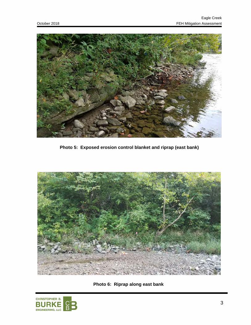
3
Photo 5: Exposed erosion control blanket and riprap (east bank)
Photo 6: Riprap along east bank
Eagle Creek
October 2018 FEH Mitigation Assessment
4
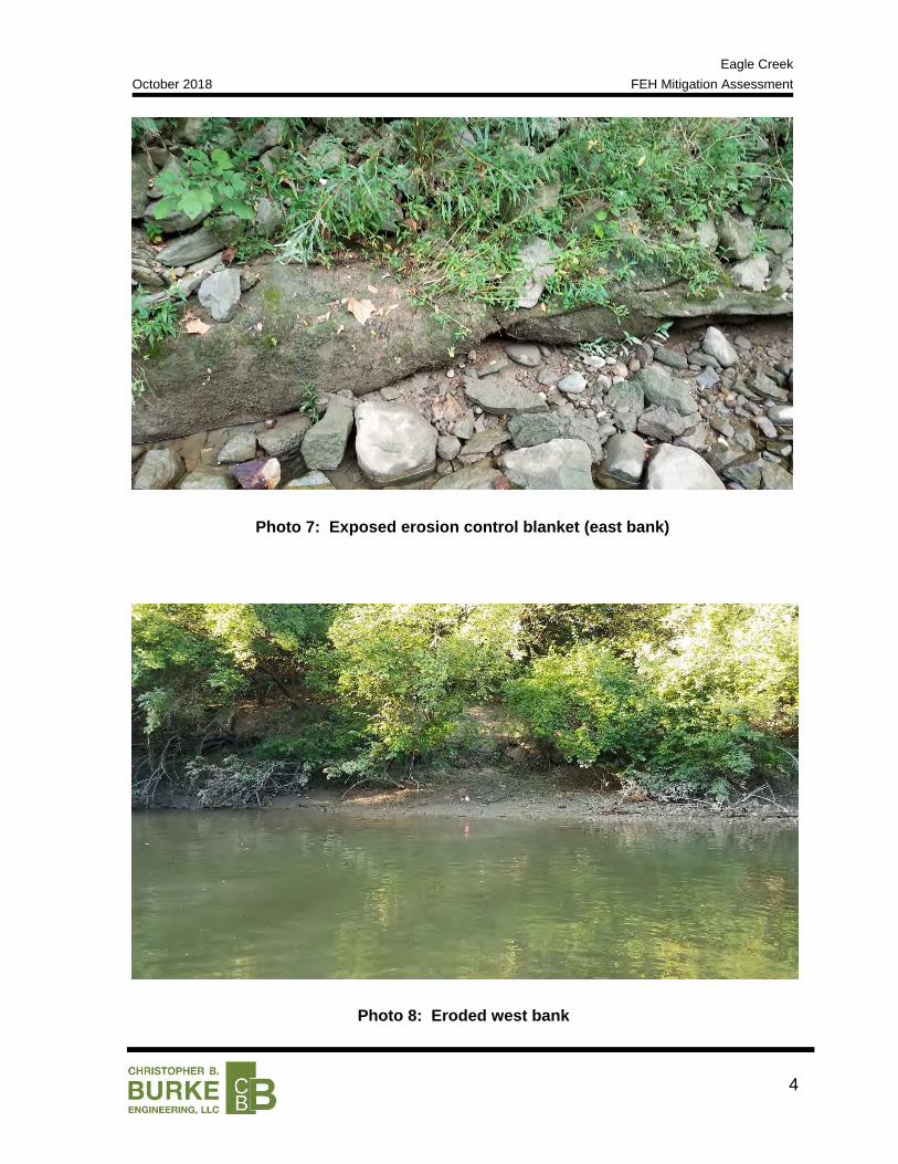
Photo 7: Exposed erosion control blanket (east bank)
Photo 8: Eroded west bank

Eagle Creek
October 2018 FEH Mitigation Assessment
5
Photo 9: Upstream of site (west bank)
Photo 10: Looking downstream towards site
Eagle Creek
October 2018 FEH Mitigation Assessment
6
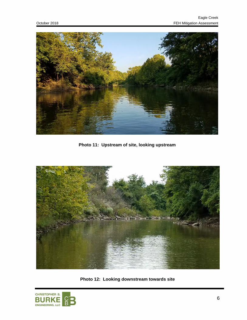
Photo 11: Upstream of site, looking upstream
Photo 12: Looking downstream towards site

Eagle Creek October 2018 FEH Mitigation Assessment
Appendix 2: Site Assessment Data & Calculations

Dandy Trail Site FEH Mitigation October 2018 along Eagle Creek
Bankfull Cross Section Plot

Bankfull Channel Cross‐section Properties
726
728
730
732
734
736
738
740
742
0
2
4
6
8
10
12
14
16
0.1 1.0 10.0 100.0 1000.0 10000.0
Elevation (ft, N
AVD8
8)
Max Flow Dep
th (ft)
Area (ft2) Top Width (ft) Hydraulic Radius (ft)
Area Top Width Hydraulic Radius
720.0
725.0
730.0
735.0
740.0
745.0
750.0
0 20 40 60 80 100 120 140
Elevation (ft, NAV
D88
)
Station (ft)
Channel Bankfull WSE

Dandy Trail Site FEH Mitigation October 2018 along Eagle Creek
Stream Classification Sheet
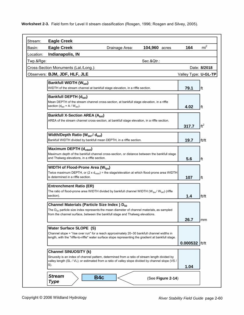
Worksheet 2-3. Field form for Level II stream classification (Rosgen, 1996; Rosgen and Silvey, 2005).
104,960 acres 164 mi2
Date: 8/2018
U-GL-TP
Bankfull WIDTH (Wbkf)
WIDTH of the stream channel at bankfull stage elevation, in a riffle section. ft
Bankfull DEPTH (dbkf)
ft
Bankfull X-Section AREA (Abkf)
ft2
Width/Depth Ratio (Wbkf / dbkf)
Bankfull WIDTH divided by bankfull mean DEPTH, in a riffle section. ft/ft
Maximum DEPTH (dmbkf)
ft
WIDTH of Flood-Prone Area (Wfpa)
ft
Entrenchment Ratio (ER)
ft/ft
Channel Materials (Particle Size Index ) D50
mm
Water Surface SLOPE (S)
ft/ft
Channel SINUOSITY (k)
Mean DEPTH of the stream channel cross-section, at bankfull stage elevation, in a riffle section (dbkf = A / Wbkf).
AREA of the stream channel cross-section, at bankfull stage elevation, in a riffle section.
Maximum depth of the bankfull channel cross-section, or distance between the bankfull stage and Thalweg elevations, in a riffle section.
Channel slope = "rise over run" for a reach approximately 20–30 bankfull channel widths in length, with the "riffle-to-riffle" water surface slope representing the gradient at bankfull stage.
Sinuosity is an index of channel pattern, determined from a ratio of stream length divided by valley length (SL / VL); or estimated from a ratio of valley slope divided by channel slope (VS / S).
79.1
4.02
B4c
Twice maximum DEPTH, or (2 x dmbkf) = the stage/elevation at which flood-prone area WIDTH is determined in a riffle section.
The ratio of flood-prone area WIDTH divided by bankfull channel WIDTH (W fpa / Wbkf) (riffle section).
The D50 particle size index represents the mean diameter of channel materials, as sampled from the channel surface, between the bankfull stage and Thalweg elevations.
317.7
19.7
5.6
1.04
107
1.4
26.7
0.000532
Eagle Creek
Sec.&Qtr.:
Cross-Section Monuments (Lat./Long.):
Stream:
Drainage Area:
Observers:
Twp.&Rge:
Location:
Basin:
Indianapolis, IN
Eagle Creek
Valley Type:BJM, JDF, HLF, JLE
Stream Type
(See Figure 2-14)
Copyright © 2006 Wildland Hydrology River Stability Field Guide page 2-60

Dandy Trail Site FEH Mitigation October 2018 along Eagle Creek
Geotechnical Investigation
670
680
690
700
710
720
730
740
750
760
670
680
690
700
710
720
730
740
750
760
0 20 40 60 80 100 120 140 160
As Shown
PEAT WEATHEREDSHALE
W
STANDARD PENETRATION INBLOWS PER FOOT (N)
TOPSOIL
Date
SOIL PROFILESILTSTONE
SAND/GRAVEL
CLAY
N
GROUND WATER DURINGDRILLING
Page
Christopher B. Burke Engineering, LTD
09050035INDReviewed By
Drawn By
SHALE
Project No.
CG
LIMESTONE
BITUMINOUSCONCRETE
PORTLAND CEMENTCONCRETE
MOISTURE CONTENT INPERCENT (w)
GROUND WATER ATCOMPLETION OF DRILLING
CRUSHED AGGREGATEGRAVEL/COBBLES
FILL
SILT
SAND
CLAYSHALE
COALBOULDERS
1 of 1
LEGEND
12/10/10Indianapolis, Indiana
Scale
City of Indianapolis PALSANDSTONE
GROUND WATER AT "N"HOURS AFTER COMPLETION
SOIL PROFILE_STATION 09050035IND.GPJ CTL.GDT 12/10/10
LEVEE
SM
CL-ML SW-SM
CL-ML
SW-SM
CL-ML
LEVEE EC-12(c)CROSS SECTION "A"
Eagle Creek
50/5"50/3"50/4"50/5"50/4"50/5"50/5"
50/4"
50/3"
147
1222
81066410129
8
12
12
EC-12-21662802.73150777.10
---748
27812152434432024404562
76
60
32377241011102526274348294767
50/4"
50/4"50/5"50/3"50/5"
50/5"
50/3"
50/2"
50/3"
50/2"
50/3"
91212
109119978
9
8
11
EC-12-31662814.73150858.10
---754.5
671113192137402431332841494249
40
56
50/5"50/2"50/4"50/2"
50/3"
50/4"
1111211821
12109
10
9
10
EC-12-71662429.04150846.36
---738
SM
Embankment Fill_SM
Sands1_SM
Clays1_CL-MLSands2_SW-SM
Clays2_CL-ML
Sands3_SW-SM
Clays3_CL-ML
1.714
EC
-12-
2
EC
-12-
3
Case: End of Construction
Indianapolis PAL Levee Accrediation ProjectLevee: EC-12Cross Section: A
Water Side Analysis - Effective Stress
Distance
0 20 40 60 80 100 120 140 160 180 200 220 240
Ele
vatio
n
670
680
690
700
710
720
730
740
750
760
770
670
680
690
700
710
720
730
740
750
760
670
680
690
700
710
720
730
740
750
760
0 20 40 60 80 100 120 140 160 180 200 220 240
As Shown
PEAT WEATHEREDSHALE
W
STANDARD PENETRATION INBLOWS PER FOOT (N)
TOPSOIL
Date
SOIL PROFILESILTSTONE
SAND/GRAVEL
CLAY
N
GROUND WATER DURINGDRILLING
Page
Christopher B. Burke Engineering, LTD
09050035INDReviewed By
Drawn By
SHALE
Project No.
CG
LIMESTONE
BITUMINOUSCONCRETE
PORTLAND CEMENTCONCRETE
MOISTURE CONTENT INPERCENT (w)
GROUND WATER ATCOMPLETION OF DRILLING
CRUSHED AGGREGATEGRAVEL/COBBLES
FILL
SILT
SAND
CLAYSHALE
COALBOULDERS
1 of 1
LEGEND
12/10/10Indianapolis, Indiana
Scale
City of Indianapolis PALSANDSTONE
GROUND WATER AT "N"HOURS AFTER COMPLETION
SOIL PROFILE_STATION 09050035IND.GPJ CTL.GDT 12/10/10
Eagle Creek
LEVEE EC-12(c)CROSS SECTION "B"
LEVEE 18161126151922
48
50/5"
50/2"50/4"50/5"50/2"50/3"50/4"50/3"50/4"50/2"50/5"50/4"50/5"
50/4"
50/3"
50/3"
913
69
961191081010127
8
8
13
EC-12-41662421.07151114.20
---745
1416
121111999131517482434343063
12
62
50/2"
50/3"50/5"
50/3"
50/4"
50/4"
50/5"
12129151119
108
8910
9
10
11
12
9
EC-12-51662390.36151030.86
---755
671113192137402431332841494249
40
56
50/5"50/2"50/4"50/2"
50/3"
50/4"
1111211821
12109
10
9
10
EC-12-71662429.04150846.36
---738
SM
SM
SM
CL-ML
CL-ML
SW-SM
CL-ML
Sands1_SM
Embankment Fill_SM
Sands1_SM
Clays 1_CL-ML
Sands 2_SM
Clays 2_CL-ML
Sands 3_SW-SM
Clays 3_CL-ML
Sands 3_SW-SM
0.882
EC
-12-
4
EC
-12-
7 EC
-12-
5
Eagle Creek
Case: Rapid Drawdown
Indianapolis PAL Levee Accrediation ProjectLevee: EC-12Cross Section: B
Water Side Analysis
Distance
0 20 40 60 80 100 120 140 160 180 200 220 240 260
Ele
vatio
n
660
670
680
690
700
710
720
730
740
750
760
670
680
690
700
710
720
730
740
750
760
670
680
690
700
710
720
730
740
750
760
SOIL PROFILE
SAND/GRAVEL
CLAY
N
GROUND WATER DURINGDRILLING
Page
Lean Clay - CL
Christopher B. Burke Engineering, LTD
09050035INDReviewed By
Drawn By
SHALE
-250 -200 -150 -100 50 0 50 100 150
Project No.
CG
LIMESTONE
BITUMINOUSCONCRETE
PORTLAND CEMENTCONCRETE
MOISTURE CONTENT INPERCENT (w)
GROUND WATER ATCOMPLETION OF DRILLING
CRUSHED AGGREGATEGRAVEL/COBBLES
FILL
SILT
SAND
CLAYSHALE
COALBOULDERS
1 of 1
LEGEND
5/27/11Indianapolis, Indiana
Scale
City of Indianapolis PALSANDSTONE
GROUND WATER AT "N"HOURS AFTER COMPLETION
Fat Clay - CH
As Shown
PEAT
W
STANDARD PENETRATION INBLOWS PER FOOT (N)
TOPSOIL
Date
ASTM_PROFILE 09050035IND.GPJ CTL.GDT 5/27/11
-300
Eagle Creek
SW-SM
Levee SM/CL-ML
CL-ML
SW-SM
CL-ML
SW-SM
LEVEE EC-12(c)CROSS SECTION "C"
CL-MLDetention PondEstimated Bottom
43549756545332818274347504758606350/5"
50/2"
50/2"
8614141319173323189
9
10
EC-12-6755
671113192137402431332841494249
40
56
50/5"50/2"50/4"50/2"
50/3"
50/4"
1111211821
12109
10
9
10
EC-12-7738
SM
Embankment Fill_SM
Sands1_SM
Clays 1_CL-ML
Sands 2_SW-SM
Clays 2_CL-ML
Sands 3_SW-SM
Clays 3_CL-ML
Sands 4_SW-SM
2.721
Detention Pond (Dry Condition)
EC
-12-
6
Eagle Creek
Case: End of Construction - Total Stress
Water Side Analysis
Indianapolis PAL Levee Accrediation ProjectLevee: EC-12Cross Section: C
Distance
-220 -200 -180 -160 -140 -120 -100 -80 -60 -40 -20 0 20 40 60 80 100 120 140 160 180
Ele
vatio
n
660
670
680
690
700
710
720
730
740
750
760

Geotechnical Investigation City of Indianapolis PAL Levee Accreditation Project Levee EC-12(c) CTL Project No.: 09050035IND June 6, 2011 Page 8
Table 3 – Summary of Factor of Safety for Slope Stability
Parameter Factor of Safety for Slope Stability
Existing Condition
Steady Seepage
Rapid Drawdown Earthquake
Side of Levee Water Dry Water Dry Water Dry Water Dry Cross Section “A” 1.7 3.9 1.62 3.0 1.6 --- 1.1 2.2 Cross Section “B” < 1.0 --- 0.8 2.8 0.8 3.1 not performed Cross Section “C” 2.4 1.9 2.6 1.8 2.6 1.9 1.9 1.4
Minimum Allowed* 1.3 1.4 1.0 to 1.2 1.0 * Refer to EM 1110-2-1913, Table 6-1b
Various permanent methods of repair are available for consideration, including gabion walls, sheet piling with and/or without tiebacks, and riprap. As a temporary solution, the erosion along the east back of Eagle Creek was repaired with a limited amount of riprap due to construction restraints. The temporary erosion repair using riprap along the river bank was analyzed. By analyzing the levee at the location of Cross Section B after the application of riprap, results of the stability analysis indicate that the entire levee system is stable. However, the levee system does not meet the minimum factor of safety requirements as shown in Table 4 below.
Table 4 – Summary of Factor of Safety for Slope Stability (Using Riprap)
Parameter Factor of Safety for Slope Stability Using Riprap
Existing Condition
Steady Seepage
Rapid Drawdown Earthquake
Side of Levee Water Dry Water Dry Water Dry Water Dry Cross Section “B” 1.0 3.1 1.1 2.8 1.0 3.3 0.8 2.0
Minimum Allowed* 1.3 1.4 1.0 to 1.2 1.0 * Refer to EM 1110-2-1913, Table 6-1b

Eagle Creek October 2018 FEH Mitigation Assessment
Appendix 3: Watershed-scale Assessment Data & Calculations
Dandy Trail Site FEH Mitigation October 2018 along Eagle Creek
Approximate Bankfull Location Map and Bankfull Dimension Comparison
¬«5
¬«2
¬«4
¬«13
¬«22
¬«17
¬«27
¬«24
¬«7
¬«26
¬«3
¬«23
¬«21
¬«25
¬«15
¬«6
¬«10
¬«30
¬«14
¬«29
¬«16
¬«18¬«19 ¬«20
¬«9
¬«28
¬«1
¬«8
¬«12
¬« 11
±Sources of Data:1. Aerial Photography: 2017 Marion County Orthophotography.2. Roads, Indiana Department of Transportation, 2015.3. County Boundaries, US Bureau of the Census tigerfiles, 2017.
Christopher B. Burke Engineering, LLCPNC Center, Suite 1368 South115 West Washington StreetIndianapolis, Indiana 46204(t) 317.266.8000 (f) 317.632.3306
PROJECT:
TITLE:
PROJECT NO. APPROX. SCALE
EXHIBIT
DATE:
Eagle CreekFEH Mitigation Assessment
Approximate Bankfull Location Map
14-0014
A3.210/2018
LegendApproximate Bankfull Location
Eagle Creek
1 " = 5,000 '
£¤36
§̈¦65
£¤136
§̈¦74
§̈¦465
£¤40 §̈¦70
Measurement LocationMiles from Mouth
(mi)
Approximate Distance DS from
Dam(mi)
Drainage Area(sq. mi.)
ApproximateBankfull Width*
(ft)
Predicted Bankfull Width**
(ft)
Predicted Bankfull Depth**
(ft)
Predicted Bankfull Area**
(ft2)
Departure from Expected Bankfull Width
(ft [%])Description of Stream atMeasurement Location
1 10.818 0.3 162.0 50 96 3.6 343 ‐46 ft [‐48%] Alluvium2 10.64 0.5 163.0 80 96 3.6 344 ‐16 ft [‐17%] Alluvium3 10.386 0.7 164.0 40 96 3.6 345 ‐56 ft [‐59%] Alluvium4 10.181 0.9 164.0 35 96 3.6 345 ‐61 ft [‐64%] Alluvium5 9.981 1.1 165.0 40 97 3.6 346 ‐57 ft [‐59%] Alluvium6 9.754 1.3 165.0 80 97 3.6 346 ‐17 ft [‐17%] Alluvium7 9.535 1.6 165.0 25 97 3.6 346 ‐72 ft [‐74%] Alluvium8 9.305 1.8 166.0 45 97 3.6 347 ‐52 ft [‐54%] Alluvium9 9.073 2.0 166.0 75 97 3.6 347 ‐22 ft [‐23%] Alluvium10 8.853 2.2 169.0 55 97 3.6 350 ‐42 ft [‐44%] Alluvium11 8.482 2.6 169.0 45 97 3.6 350 ‐52 ft [‐54%] Alluvium12 8.03 3.1 170.0 30 98 3.6 351 ‐68 ft [‐69%] Alluvium13 7.648 3.5 170.0 45 98 3.6 351 ‐53 ft [‐54%] Alluvium14 7.214 3.9 173.0 75 98 3.6 354 ‐23 ft [‐24%] Alluvium15 6.839 4.3 174.0 40 98 3.6 355 ‐58 ft [‐59%] Alluvium16 6.235 4.9 174.0 65 98 3.6 355 ‐33 ft [‐34%] Alluvium17 5.651 5.4 175.0 40 99 3.6 356 ‐59 ft [‐59%] Alluvium18 5.128 6.0 175.0 70 99 3.6 356 ‐29 ft [‐29%] Alluvium19 4.708 6.4 177.0 20 99 3.6 358 ‐79 ft [‐80%] Alluvium20 4.356 6.7 177.0 35 99 3.6 358 ‐64 ft [‐65%] Alluvium21 3.819 7.3 177.0 35 99 3.6 358 ‐64 ft [‐65%] Alluvium22 3.409 7.7 205.0 50 104 3.7 385 ‐54 ft [‐52%] Alluvium23 3.025 8.1 208.0 40 104 3.7 388 ‐64 ft [‐62%] Alluvium24 2.578 8.5 209.0 145 104 3.7 388 41 ft [39%] Alluvium25 2.195 8.9 209.0 50 104 3.7 388 ‐54 ft [‐52%] Alluvium26 1.792 9.3 209.0 130 104 3.7 388 26 ft [25%] Alluvium27 1.43 9.7 210.0 45 105 3.7 389 ‐60 ft [‐57%] Alluvium28 1.081 10.0 210.0 45 105 3.7 389 ‐60 ft [‐57%] Alluvium29 0.654 10.4 210.0 65 105 3.7 389 ‐40 ft [‐38%] Alluvium30 0.174 10.9 210.0 35 105 3.7 389 ‐70 ft [‐67%] Alluvium
* Approximate bankfull width measured from cross‐sections of the IndianaMap DEM. The channel width was measured at an elevation that was the predicted bankfull depth above the invert of the cross‐section. This method is expected to produce bankfull widths that will be slightly higher than those that would be measured in the field (if bankfull indicators could be reasonably identified).** Predicted bankfull width and depth determined using the Central Till Plain Region regression equations published by the USGS in Regional Bankfull‐Channel Dimensions of Non‐Urban Wadeable Streams in Indiana.

Eagle Creek October 2018 FEH Mitigation Assessment
Appendix 4: Reach-scale Assessment Data & Calculations

Dandy Trail Site FEH Mitigation October 2018 along Eagle Creek
Stream Gage Analysis

1 Program PeakFq U. S. GEOLOGICAL SURVEY Seq.002.000 Version 7.2 Annual peak flow frequency analysis Run Date / Time 3/28/2018 07/02/2018 13:46
--- PROCESSING OPTIONS ---
Plot option = Graphics device Basin char output = None Print option = Yes Debug print = No Input peaks listing = Long Input peaks format = WATSTORE peak file
Input files used: peaks (ascii) - C:\Users\hfinfrock\Desktop\PEAK_CLERMONT.TXT specifications - C:\Users\hfinfrock\Desktop\PKFQWPSF.TMP Output file(s): main - C:\Users\hfinfrock\Desktop\PEAK_CLERMONT.PRT
*** User responsible for assessment and interpretation of the following analysis *** 1
Program PeakFq U. S. GEOLOGICAL SURVEY Seq.001.001 Version 7.2 Annual peak flow frequency analysis Run Date / Time 3/28/2018 07/02/2018 13:46 Station - 03353460 EAGLE CREEK AT CLERMONT, IN
TABLE 1 - INPUT DATA SUMMARY
Number of peaks in record = 11 Peaks not used in analysis = 0 Gaged peaks in analysis = 11 Historic peaks in analysis = 0 Beginning Year = 2007 Ending Year = 2017 Historical Period Length = 11 Skew option = WEIGHTED Regional skew = -0.200 Standard error = 0.550 Mean Square error = 0.303 Gage base discharge = 0.0 User supplied high outlier threshold = -- User supplied PILF (LO) criterion = -- Plotting position parameter = 0.00 Type of analysis BULL.17B PILF (LO) Test Method MGBT Perceptible Ranges = Not Applicable
1
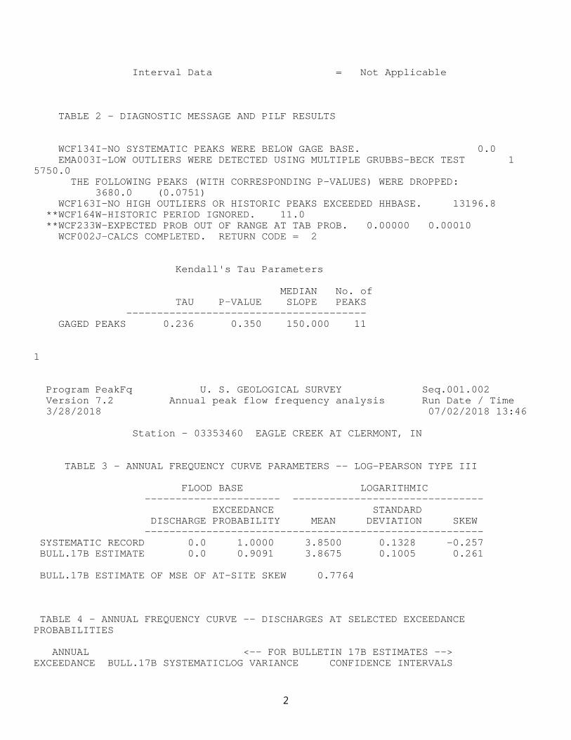
Interval Data = Not Applicable
TABLE 2 - DIAGNOSTIC MESSAGE AND PILF RESULTS
WCF134I-NO SYSTEMATIC PEAKS WERE BELOW GAGE BASE. 0.0 EMA003I-LOW OUTLIERS WERE DETECTED USING MULTIPLE GRUBBS-BECK TEST 1 5750.0 THE FOLLOWING PEAKS (WITH CORRESPONDING P-VALUES) WERE DROPPED: 3680.0 (0.0751) WCF163I-NO HIGH OUTLIERS OR HISTORIC PEAKS EXCEEDED HHBASE. 13196.8 **WCF164W-HISTORIC PERIOD IGNORED. 11.0 **WCF233W-EXPECTED PROB OUT OF RANGE AT TAB PROB. 0.00000 0.00010 WCF002J-CALCS COMPLETED. RETURN CODE = 2
Kendall's Tau Parameters
MEDIAN No. of TAU P-VALUE SLOPE PEAKS --------------------------------------- GAGED PEAKS 0.236 0.350 150.000 11
1
Program PeakFq U. S. GEOLOGICAL SURVEY Seq.001.002 Version 7.2 Annual peak flow frequency analysis Run Date / Time 3/28/2018 07/02/2018 13:46 Station - 03353460 EAGLE CREEK AT CLERMONT, IN
TABLE 3 - ANNUAL FREQUENCY CURVE PARAMETERS -- LOG-PEARSON TYPE III
FLOOD BASE LOGARITHMIC ---------------------- ------------------------------- EXCEEDANCE STANDARD DISCHARGE PROBABILITY MEAN DEVIATION SKEW ------------------------------------------------------- SYSTEMATIC RECORD 0.0 1.0000 3.8500 0.1328 -0.257 BULL.17B ESTIMATE 0.0 0.9091 3.8675 0.1005 0.261
BULL.17B ESTIMATE OF MSE OF AT-SITE SKEW 0.7764
TABLE 4 - ANNUAL FREQUENCY CURVE -- DISCHARGES AT SELECTED EXCEEDANCE PROBABILITIES
ANNUAL <-- FOR BULLETIN 17B ESTIMATES -->EXCEEDANCE BULL.17B SYSTEMATICLOG VARIANCE CONFIDENCE INTERVALS
2
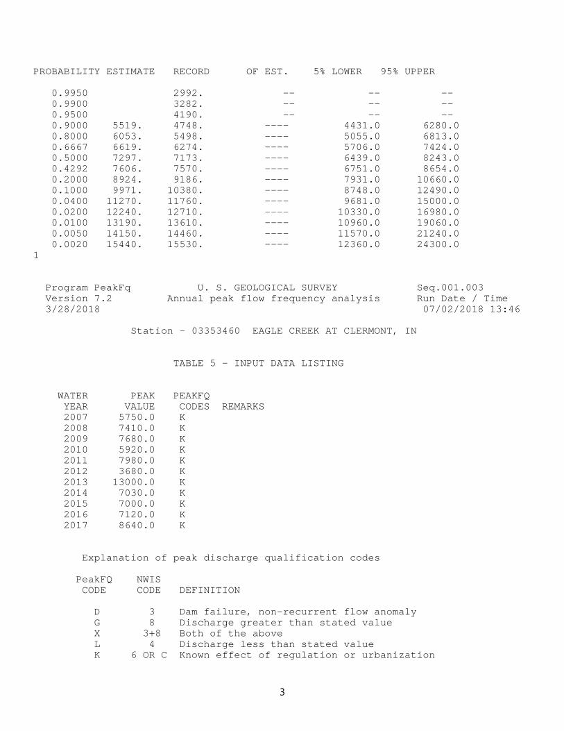
PROBABILITY ESTIMATE RECORD OF EST. 5% LOWER 95% UPPER
0.9950 2992. -- -- -- 0.9900 3282. -- -- -- 0.9500 4190. -- -- -- 0.9000 5519. 4748. ---- 4431.0 6280.0 0.8000 6053. 5498. ---- 5055.0 6813.0 0.6667 6619. 6274. ---- 5706.0 7424.0 0.5000 7297. 7173. ---- 6439.0 8243.0 0.4292 7606. 7570. ---- 6751.0 8654.0 0.2000 8924. 9186. ---- 7931.0 10660.0 0.1000 9971. 10380. ---- 8748.0 12490.0 0.0400 11270. 11760. ---- 9681.0 15000.0 0.0200 12240. 12710. ---- 10330.0 16980.0 0.0100 13190. 13610. ---- 10960.0 19060.0 0.0050 14150. 14460. ---- 11570.0 21240.0 0.0020 15440. 15530. ---- 12360.0 24300.01
Program PeakFq U. S. GEOLOGICAL SURVEY Seq.001.003 Version 7.2 Annual peak flow frequency analysis Run Date / Time 3/28/2018 07/02/2018 13:46 Station - 03353460 EAGLE CREEK AT CLERMONT, IN
TABLE 5 - INPUT DATA LISTING
WATER PEAK PEAKFQ YEAR VALUE CODES REMARKS 2007 5750.0 K 2008 7410.0 K 2009 7680.0 K 2010 5920.0 K 2011 7980.0 K 2012 3680.0 K 2013 13000.0 K 2014 7030.0 K 2015 7000.0 K 2016 7120.0 K 2017 8640.0 K
Explanation of peak discharge qualification codes
PeakFQ NWIS CODE CODE DEFINITION
D 3 Dam failure, non-recurrent flow anomaly G 8 Discharge greater than stated value X 3+8 Both of the above L 4 Discharge less than stated value K 6 OR C Known effect of regulation or urbanization
3
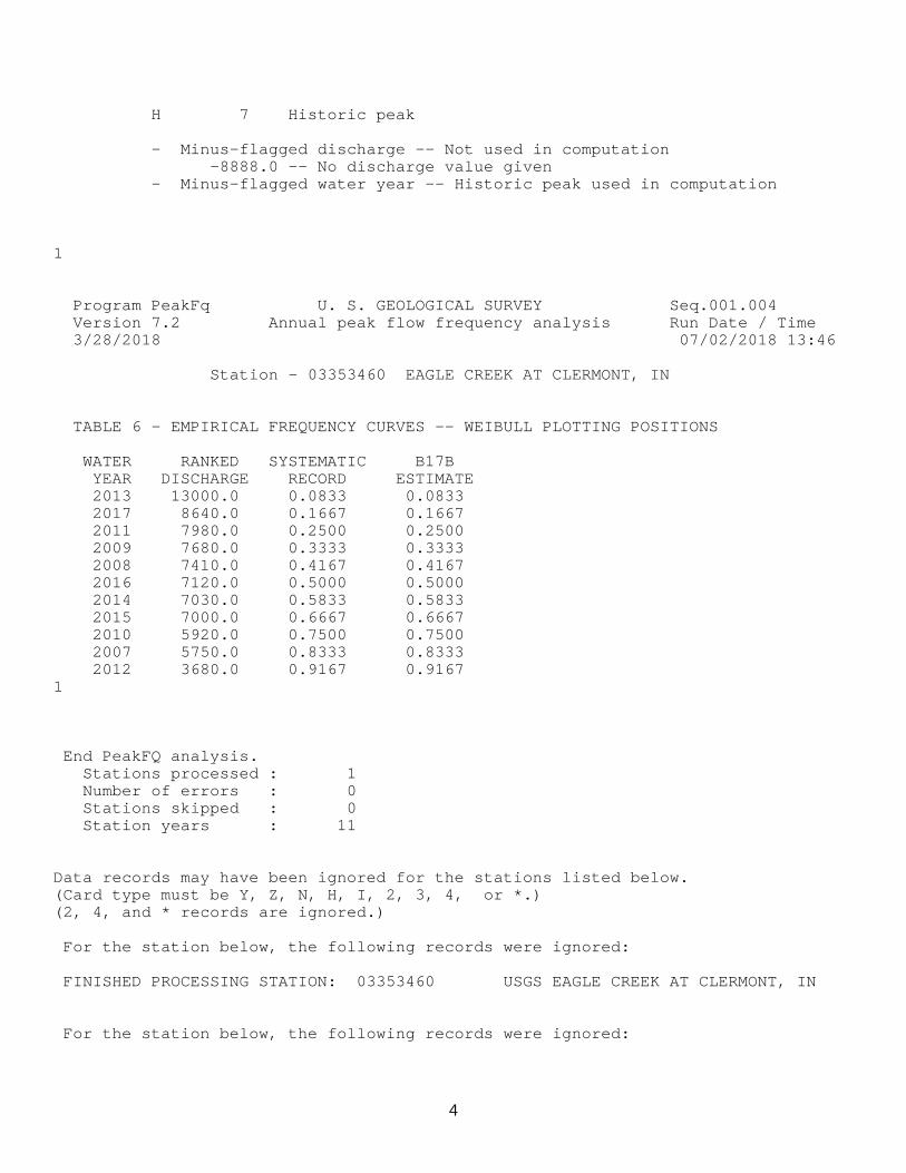
H 7 Historic peak
- Minus-flagged discharge -- Not used in computation -8888.0 -- No discharge value given - Minus-flagged water year -- Historic peak used in computation
1
Program PeakFq U. S. GEOLOGICAL SURVEY Seq.001.004 Version 7.2 Annual peak flow frequency analysis Run Date / Time 3/28/2018 07/02/2018 13:46 Station - 03353460 EAGLE CREEK AT CLERMONT, IN
TABLE 6 - EMPIRICAL FREQUENCY CURVES -- WEIBULL PLOTTING POSITIONS
WATER RANKED SYSTEMATIC B17B YEAR DISCHARGE RECORD ESTIMATE 2013 13000.0 0.0833 0.0833 2017 8640.0 0.1667 0.1667 2011 7980.0 0.2500 0.2500 2009 7680.0 0.3333 0.3333 2008 7410.0 0.4167 0.4167 2016 7120.0 0.5000 0.5000 2014 7030.0 0.5833 0.5833 2015 7000.0 0.6667 0.6667 2010 5920.0 0.7500 0.7500 2007 5750.0 0.8333 0.8333 2012 3680.0 0.9167 0.9167 1
End PeakFQ analysis. Stations processed : 1 Number of errors : 0 Stations skipped : 0 Station years : 11
Data records may have been ignored for the stations listed below. (Card type must be Y, Z, N, H, I, 2, 3, 4, or *.) (2, 4, and * records are ignored.) For the station below, the following records were ignored: FINISHED PROCESSING STATION: 03353460 USGS EAGLE CREEK AT CLERMONT, IN For the station below, the following records were ignored:
4

FINISHED PROCESSING STATION:
5
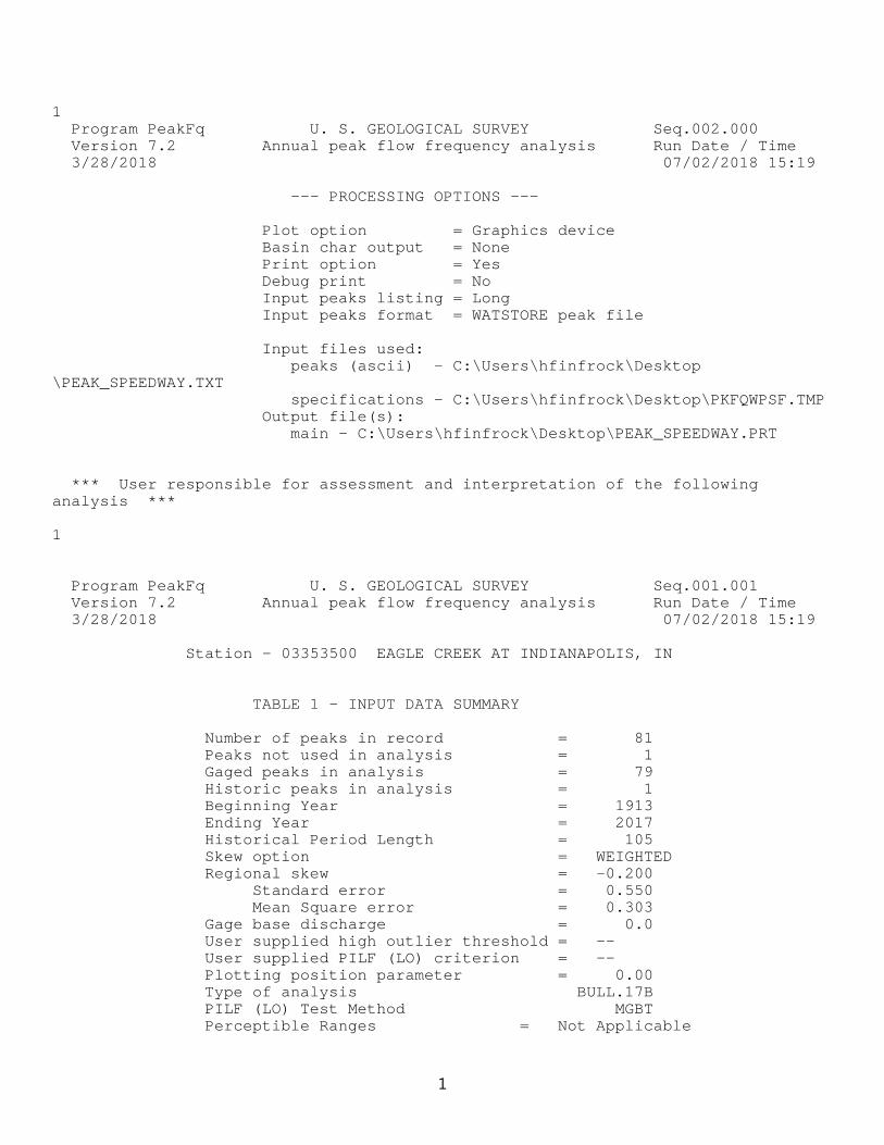
1 Program PeakFq U. S. GEOLOGICAL SURVEY Seq.002.000 Version 7.2 Annual peak flow frequency analysis Run Date / Time 3/28/2018 07/02/2018 15:19
--- PROCESSING OPTIONS ---
Plot option = Graphics device Basin char output = None Print option = Yes Debug print = No Input peaks listing = Long Input peaks format = WATSTORE peak file
Input files used: peaks (ascii) - C:\Users\hfinfrock\Desktop\PEAK_SPEEDWAY.TXT specifications - C:\Users\hfinfrock\Desktop\PKFQWPSF.TMP Output file(s): main - C:\Users\hfinfrock\Desktop\PEAK_SPEEDWAY.PRT
*** User responsible for assessment and interpretation of the following analysis *** 1
Program PeakFq U. S. GEOLOGICAL SURVEY Seq.001.001 Version 7.2 Annual peak flow frequency analysis Run Date / Time 3/28/2018 07/02/2018 15:19 Station - 03353500 EAGLE CREEK AT INDIANAPOLIS, IN
TABLE 1 - INPUT DATA SUMMARY
Number of peaks in record = 81 Peaks not used in analysis = 1 Gaged peaks in analysis = 79 Historic peaks in analysis = 1 Beginning Year = 1913 Ending Year = 2017 Historical Period Length = 105 Skew option = WEIGHTED Regional skew = -0.200 Standard error = 0.550 Mean Square error = 0.303 Gage base discharge = 0.0 User supplied high outlier threshold = -- User supplied PILF (LO) criterion = -- Plotting position parameter = 0.00 Type of analysis BULL.17B PILF (LO) Test Method MGBT Perceptible Ranges = Not Applicable
1
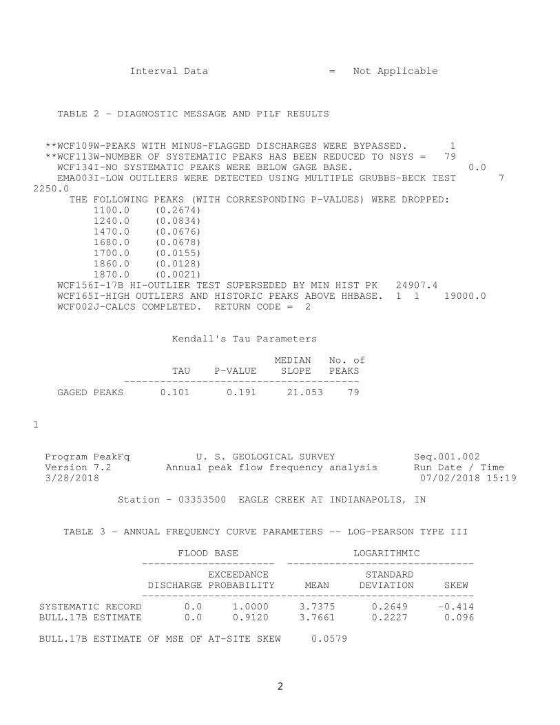
Interval Data = Not Applicable
TABLE 2 - DIAGNOSTIC MESSAGE AND PILF RESULTS
**WCF109W-PEAKS WITH MINUS-FLAGGED DISCHARGES WERE BYPASSED. 1 **WCF113W-NUMBER OF SYSTEMATIC PEAKS HAS BEEN REDUCED TO NSYS = 79 WCF134I-NO SYSTEMATIC PEAKS WERE BELOW GAGE BASE. 0.0 EMA003I-LOW OUTLIERS WERE DETECTED USING MULTIPLE GRUBBS-BECK TEST 7 2250.0 THE FOLLOWING PEAKS (WITH CORRESPONDING P-VALUES) WERE DROPPED: 1100.0 (0.2674) 1240.0 (0.0834) 1470.0 (0.0676) 1680.0 (0.0678) 1700.0 (0.0155) 1860.0 (0.0128) 1870.0 (0.0021) WCF156I-17B HI-OUTLIER TEST SUPERSEDED BY MIN HIST PK 24907.4 WCF165I-HIGH OUTLIERS AND HISTORIC PEAKS ABOVE HHBASE. 1 1 19000.0 WCF002J-CALCS COMPLETED. RETURN CODE = 2
Kendall's Tau Parameters
MEDIAN No. of TAU P-VALUE SLOPE PEAKS --------------------------------------- GAGED PEAKS 0.101 0.191 21.053 79
1
Program PeakFq U. S. GEOLOGICAL SURVEY Seq.001.002 Version 7.2 Annual peak flow frequency analysis Run Date / Time 3/28/2018 07/02/2018 15:19 Station - 03353500 EAGLE CREEK AT INDIANAPOLIS, IN
TABLE 3 - ANNUAL FREQUENCY CURVE PARAMETERS -- LOG-PEARSON TYPE III
FLOOD BASE LOGARITHMIC ---------------------- ------------------------------- EXCEEDANCE STANDARD DISCHARGE PROBABILITY MEAN DEVIATION SKEW ------------------------------------------------------- SYSTEMATIC RECORD 0.0 1.0000 3.7375 0.2649 -0.414 BULL.17B ESTIMATE 0.0 0.9120 3.7661 0.2227 0.096
BULL.17B ESTIMATE OF MSE OF AT-SITE SKEW 0.0579
2
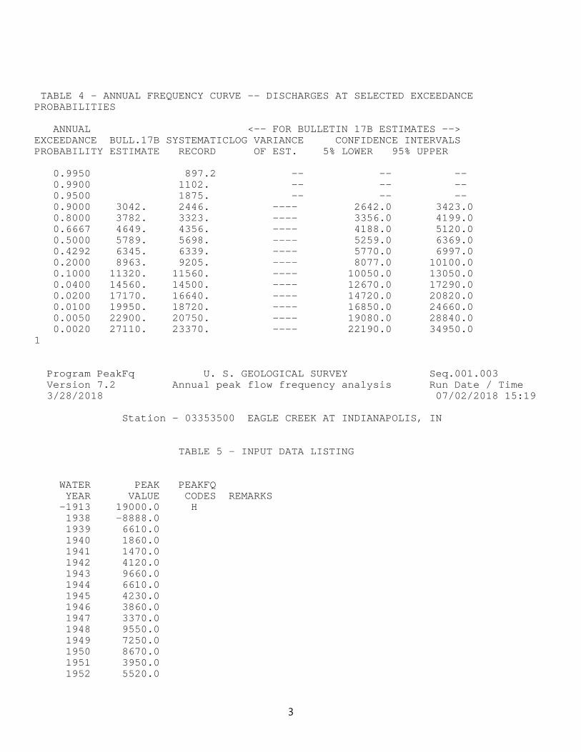
TABLE 4 - ANNUAL FREQUENCY CURVE -- DISCHARGES AT SELECTED EXCEEDANCE PROBABILITIES
ANNUAL <-- FOR BULLETIN 17B ESTIMATES -->EXCEEDANCE BULL.17B SYSTEMATICLOG VARIANCE CONFIDENCE INTERVALSPROBABILITY ESTIMATE RECORD OF EST. 5% LOWER 95% UPPER
0.9950 897.2 -- -- -- 0.9900 1102. -- -- -- 0.9500 1875. -- -- -- 0.9000 3042. 2446. ---- 2642.0 3423.0 0.8000 3782. 3323. ---- 3356.0 4199.0 0.6667 4649. 4356. ---- 4188.0 5120.0 0.5000 5789. 5698. ---- 5259.0 6369.0 0.4292 6345. 6339. ---- 5770.0 6997.0 0.2000 8963. 9205. ---- 8077.0 10100.0 0.1000 11320. 11560. ---- 10050.0 13050.0 0.0400 14560. 14500. ---- 12670.0 17290.0 0.0200 17170. 16640. ---- 14720.0 20820.0 0.0100 19950. 18720. ---- 16850.0 24660.0 0.0050 22900. 20750. ---- 19080.0 28840.0 0.0020 27110. 23370. ---- 22190.0 34950.01
Program PeakFq U. S. GEOLOGICAL SURVEY Seq.001.003 Version 7.2 Annual peak flow frequency analysis Run Date / Time 3/28/2018 07/02/2018 15:19 Station - 03353500 EAGLE CREEK AT INDIANAPOLIS, IN
TABLE 5 - INPUT DATA LISTING
WATER PEAK PEAKFQ YEAR VALUE CODES REMARKS -1913 19000.0 H 1938 -8888.0 1939 6610.0 1940 1860.0 1941 1470.0 1942 4120.0 1943 9660.0 1944 6610.0 1945 4230.0 1946 3860.0 1947 3370.0 1948 9550.0 1949 7250.0 1950 8670.0 1951 3950.0 1952 5520.0
3
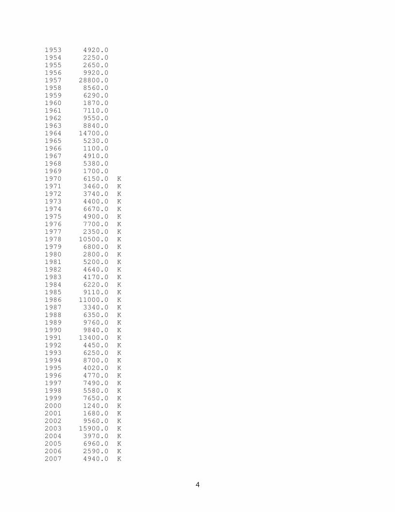
1953 4920.0 1954 2250.0 1955 2650.0 1956 9920.0 1957 28800.0 1958 8560.0 1959 6290.0 1960 1870.0 1961 7110.0 1962 9550.0 1963 8840.0 1964 14700.0 1965 5230.0 1966 1100.0 1967 4910.0 1968 5380.0 1969 1700.0 1970 6150.0 K 1971 3460.0 K 1972 3740.0 K 1973 4400.0 K 1974 6670.0 K 1975 4900.0 K 1976 7700.0 K 1977 2350.0 K 1978 10500.0 K 1979 6800.0 K 1980 2800.0 K 1981 5200.0 K 1982 4640.0 K 1983 4170.0 K 1984 6220.0 K 1985 9110.0 K 1986 11000.0 K 1987 3340.0 K 1988 6350.0 K 1989 9760.0 K 1990 9840.0 K 1991 13400.0 K 1992 4450.0 K 1993 6250.0 K 1994 8700.0 K 1995 4020.0 K 1996 4770.0 K 1997 7490.0 K 1998 5580.0 K 1999 7650.0 K 2000 1240.0 K 2001 1680.0 K 2002 9560.0 K 2003 15900.0 K 2004 3970.0 K 2005 6960.0 K 2006 2590.0 K 2007 4940.0 K
4
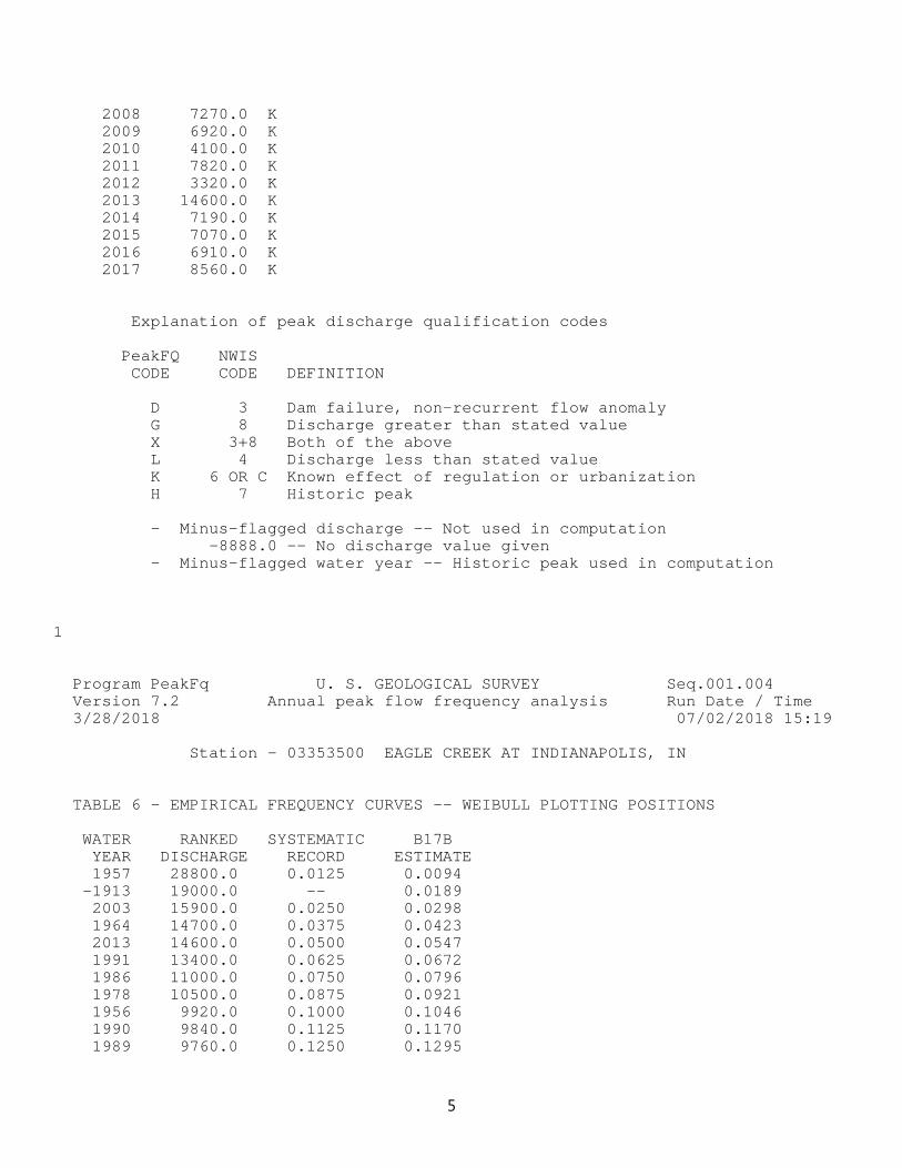
2008 7270.0 K 2009 6920.0 K 2010 4100.0 K 2011 7820.0 K 2012 3320.0 K 2013 14600.0 K 2014 7190.0 K 2015 7070.0 K 2016 6910.0 K 2017 8560.0 K
Explanation of peak discharge qualification codes
PeakFQ NWIS CODE CODE DEFINITION
D 3 Dam failure, non-recurrent flow anomaly G 8 Discharge greater than stated value X 3+8 Both of the above L 4 Discharge less than stated value K 6 OR C Known effect of regulation or urbanization H 7 Historic peak
- Minus-flagged discharge -- Not used in computation -8888.0 -- No discharge value given - Minus-flagged water year -- Historic peak used in computation
1
Program PeakFq U. S. GEOLOGICAL SURVEY Seq.001.004 Version 7.2 Annual peak flow frequency analysis Run Date / Time 3/28/2018 07/02/2018 15:19 Station - 03353500 EAGLE CREEK AT INDIANAPOLIS, IN
TABLE 6 - EMPIRICAL FREQUENCY CURVES -- WEIBULL PLOTTING POSITIONS
WATER RANKED SYSTEMATIC B17B YEAR DISCHARGE RECORD ESTIMATE 1957 28800.0 0.0125 0.0094 -1913 19000.0 -- 0.0189 2003 15900.0 0.0250 0.0298 1964 14700.0 0.0375 0.0423 2013 14600.0 0.0500 0.0547 1991 13400.0 0.0625 0.0672 1986 11000.0 0.0750 0.0796 1978 10500.0 0.0875 0.0921 1956 9920.0 0.1000 0.1046 1990 9840.0 0.1125 0.1170 1989 9760.0 0.1250 0.1295
5
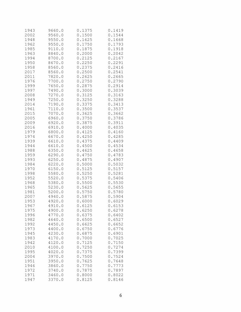
1943 9660.0 0.1375 0.1419 2002 9560.0 0.1500 0.1544 1948 9550.0 0.1625 0.1668 1962 9550.0 0.1750 0.1793 1985 9110.0 0.1875 0.1918 1963 8840.0 0.2000 0.2042 1994 8700.0 0.2125 0.2167 1950 8670.0 0.2250 0.2291 1958 8560.0 0.2375 0.2416 2017 8560.0 0.2500 0.2541 2011 7820.0 0.2625 0.2665 1976 7700.0 0.2750 0.2790 1999 7650.0 0.2875 0.2914 1997 7490.0 0.3000 0.3039 2008 7270.0 0.3125 0.3163 1949 7250.0 0.3250 0.3288 2014 7190.0 0.3375 0.3413 1961 7110.0 0.3500 0.3537 2015 7070.0 0.3625 0.3662 2005 6960.0 0.3750 0.3786 2009 6920.0 0.3875 0.3911 2016 6910.0 0.4000 0.4035 1979 6800.0 0.4125 0.4160 1974 6670.0 0.4250 0.4285 1939 6610.0 0.4375 0.4409 1944 6610.0 0.4500 0.4534 1988 6350.0 0.4625 0.4658 1959 6290.0 0.4750 0.4783 1993 6250.0 0.4875 0.4907 1984 6220.0 0.5000 0.5032 1970 6150.0 0.5125 0.5157 1998 5580.0 0.5250 0.5281 1952 5520.0 0.5375 0.5406 1968 5380.0 0.5500 0.5530 1965 5230.0 0.5625 0.5655 1981 5200.0 0.5750 0.5780 2007 4940.0 0.5875 0.5904 1953 4920.0 0.6000 0.6029 1967 4910.0 0.6125 0.6153 1975 4900.0 0.6250 0.6278 1996 4770.0 0.6375 0.6402 1982 4640.0 0.6500 0.6527 1992 4450.0 0.6625 0.6652 1973 4400.0 0.6750 0.6776 1945 4230.0 0.6875 0.6901 1983 4170.0 0.7000 0.7025 1942 4120.0 0.7125 0.7150 2010 4100.0 0.7250 0.7274 1995 4020.0 0.7375 0.7399 2004 3970.0 0.7500 0.7524 1951 3950.0 0.7625 0.7648 1946 3860.0 0.7750 0.7773 1972 3740.0 0.7875 0.7897 1971 3460.0 0.8000 0.8022 1947 3370.0 0.8125 0.8146
6
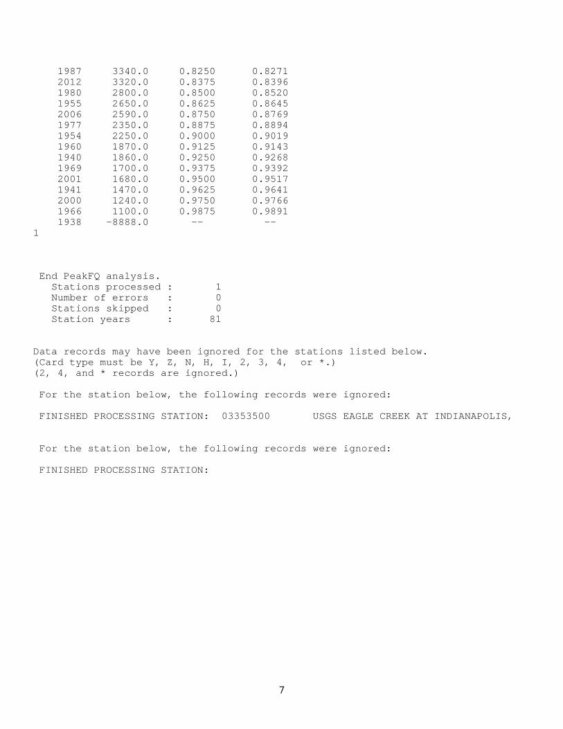
1987 3340.0 0.8250 0.8271 2012 3320.0 0.8375 0.8396 1980 2800.0 0.8500 0.8520 1955 2650.0 0.8625 0.8645 2006 2590.0 0.8750 0.8769 1977 2350.0 0.8875 0.8894 1954 2250.0 0.9000 0.9019 1960 1870.0 0.9125 0.9143 1940 1860.0 0.9250 0.9268 1969 1700.0 0.9375 0.9392 2001 1680.0 0.9500 0.9517 1941 1470.0 0.9625 0.9641 2000 1240.0 0.9750 0.9766 1966 1100.0 0.9875 0.9891 1938 -8888.0 -- -- 1
End PeakFQ analysis. Stations processed : 1 Number of errors : 0 Stations skipped : 0 Station years : 81
Data records may have been ignored for the stations listed below. (Card type must be Y, Z, N, H, I, 2, 3, 4, or *.) (2, 4, and * records are ignored.) For the station below, the following records were ignored: FINISHED PROCESSING STATION: 03353500 USGS EAGLE CREEK AT INDIANAPOLIS, For the station below, the following records were ignored: FINISHED PROCESSING STATION:
7
Dandy Trail Site FEH Mitigation October 2018 along Eagle Creek
Bankfull Discharge Calculations
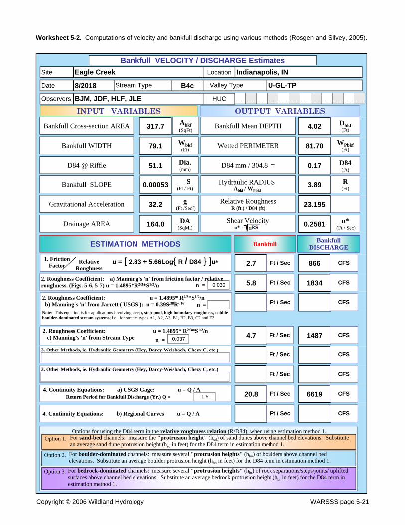
Worksheet 5-2. Computations of velocity and bankfull discharge using various methods (Rosgen and Silvey, 2005).
Site Location
Date 8/2018 B4c
Observers HUC
317.7 4.02
79.1 81.70
51.1 0.17
0.00053 3.89
32.2 23.195
164.0 0.2581
2.7 866
5.8 1834
4.7 1487
20.8 6619
BJM, JDF, HLF, JLE
Eagle Creek Indianapolis, IN
Stream Type Valley Type U-GL-TP
Bankfull VELOCITY / DISCHARGE Estimates
Feet
INPUT VARIABLES
Wbkf(Ft)
Abkf (SqFt)
Dia.(mm)
S(Ft / Ft)
Bankfull Cross-section AREA
Bankfull WIDTH
D84 @ Riffle
Bankfull SLOPE
Gravitational Acceleration
Drainage AREA
g(Ft /Sec2)
DA(SqMi)
OUTPUT VARIABLES
Bankfull Mean DEPTH Dbkf(Ft)
WPbkf(Ft)
Hydraulic RADIUS .
Wetted PERIMETER
D84 mm / 304.8 =
Relative RoughnessR (ft ) / D84 (ft)
D84(Ft)
R (Ft)
u*(Ft / Sec)
Shear Velocity
3. Other Methods, ie. Hydraulic Geometry (Hey, Darcy-Weisbach, Chezy C, etc.)
3. Other Methods, ie. Hydraulic Geometry (Hey, Darcy-Weisbach, Chezy C, etc.)
ESTIMATION METHODS Bankfull Bankfull DISCHARGE
Ft / Sec CFS
Ft / Sec CFS
4. Continuity Equations: b) Regional Curves u = Q / A
Ft / Sec CFS
Ft / Sec CFS
Ft / Sec CFS
Ft / Sec CFS
Ft / Sec CFS
Ft / Sec CFS
u = [ 2.83 + 5.66Log{ R / D84 } ]u1. FrictionFactor
_ _ _ _ _ _ _ _ _ _ _ _ _ _ _ _ _ _ _ _ _ __ _
Abkf / WPbkf
Relative Roughness
2. Roughness Coefficient: a) Manning's 'n' from friction factor / relativeroughness. (Figs. 5-6, 5-7) u = 1.4895*R2/3*S1/2/n n = 0.030
2. Roughness Coefficient: u = 1.4895* R2/3*S1/2/nb) Manning's 'n' from Jarrett ( USGS ): n = 0.39S.38R-.16 n =
Note: This equation is for applications involving steep, step-pool, high boundary roughness, cobble-boulder-dominated stream systems; i.e., for stream types A1, A2, A3, B1, B2, B3, C2 and E3.
2. Roughness Coefficient: u = 1.4895* R2/3*S1/2/nc) Manning's 'n' from Stream Type n = 0.037
Options for using the D84 term in the relative roughness relation (R/D84), when using estimation method 1.For sand-bed channels: measure the "protrusion height" (hsd) of sand dunes above channel bed elevations. Substitute an average sand dune protrusion height (hsd in feet) for the D84 term in estimation method 1.
Option 1.
Option 2.
Option 3.
For boulder-dominated channels: measure several "protrusion heights" (hbo) of boulders above channel bed elevations. Substitute an average boulder protrusion height (hbo in feet) for the D84 term in estimation method 1.
For bedrock-dominated channels: measure several "protrusion heights" (hbr) of rock separations/steps/joints/ uplifted surfaces above channel bed elevations. Substitute an average bedrock protrusion height (hbr in feet) for the D84 term in estimation method 1.
4. Continuity Equations: a) USGS Gage: u = Q / AReturn Period for Bankfull Discharge (Yr.) Q = 1.5
Copyright © 2006 Wildland Hydrology WARSSS page 5-21

Dandy Trail Site FEH Mitigation October 2018 along Eagle Creek
Flow Velocity Grids

Eagle Creek October 2018 FEH Mitigation Assessment
Bankfull Velocity Grid with flowlines
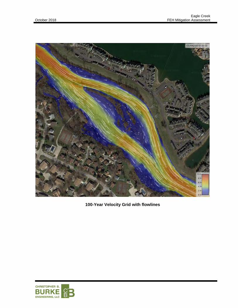
Eagle Creek October 2018 FEH Mitigation Assessment
100-Year Velocity Grid with flowlines

Dandy Trail Site FEH Mitigation October 2018 along Eagle Creek
Scour Calculations
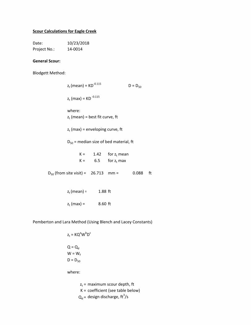
Scour Calculations for Eagle Creek
Date:
Project No.: 14-0014
General Scour:
Blodgett Method:
zt (mean) = KD-0.115
D = D50
zt (max) = KD -0.115
where:
zt (mean) = best fit curve, ft
zt (max) = enveloping curve, ft
D50 = median size of bed material, ft
K = 1.42 for zt mean
K = 6.5 for zt max
D50 (from site visit) = 26.713 mm = 0.088 ft
zt (mean) = 1.88 ft
zt (max) = 8.60 ft
Pemberton and Lara Method (Using Blench and Lacey Constants)
zt = KQaWbDc
Q = Qd
W = Wf
D = D50
where:
zt = maximum scour depth, ft
K = coefficient (see table below)
Qd = design discharge, ft3/s
10/23/2018
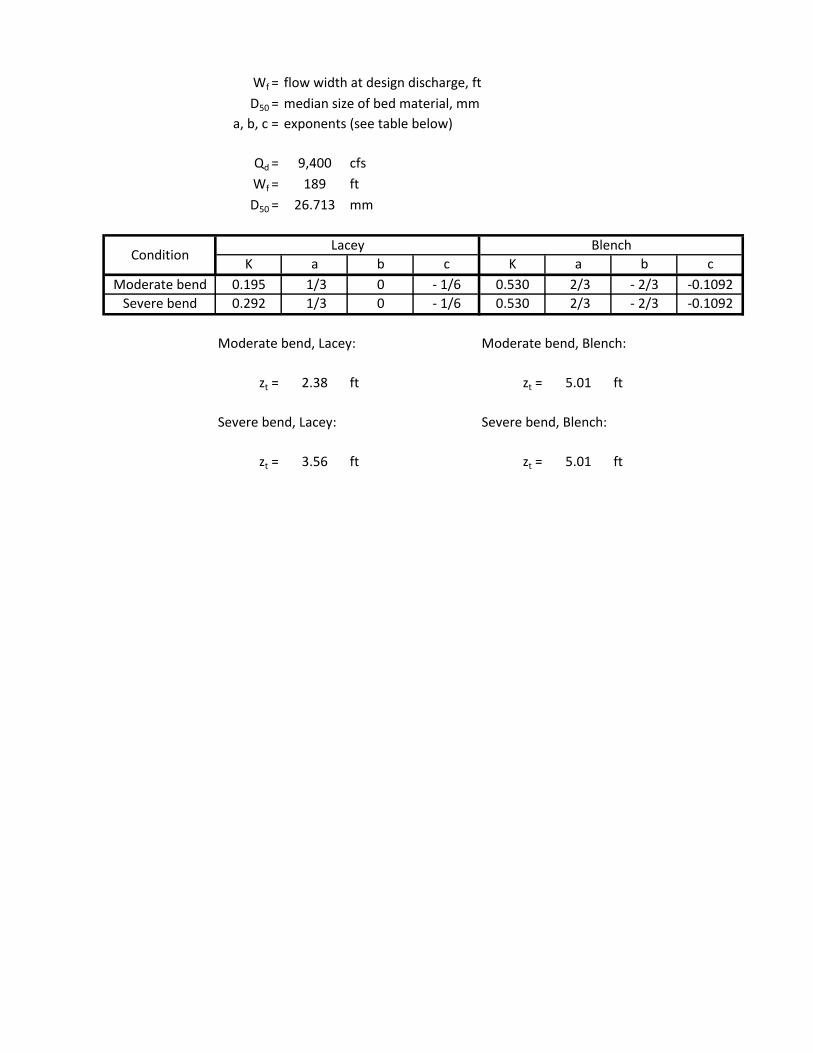
Wf = flow width at design discharge, ft
D50 = median size of bed material, mm
a, b, c = exponents (see table below)
Qd = 9,400 cfs
Wf = 189 ft
D50 = 26.713 mm
K a b c K a b c
Moderate bend 0.195 1/3 0 - 1/6 0.530 2/3 - 2/3 -0.1092
Severe bend 0.292 1/3 0 - 1/6 0.530 2/3 - 2/3 -0.1092
Moderate bend, Lacey: Moderate bend, Blench:
zt = 2.38 ft zt = 5.01 ft
Severe bend, Lacey: Severe bend, Blench:
zt = 3.56 ft zt = 5.01 ft
Bend Scour:
NEH654.09 Method:
zb = y (ymax/y -1)
where:
y = average flow depth in the bend (ft)
ymax = maximum flow depth in the bend (ft)
y = 10.5 ft
ymax/y = 1.5 + 4.5 (Wi/Rc)
where:
Wi = channel width at bend inflection point, ft
Rc = bend radius of curvature, ft
Wi = 189 ft, from aerial photograph
Rc = 690 ft, from aerial photograph
ymax/y = 2.73 ft
zb = 18.19 ft
ConditionLacey Blench
Dandy Trail Site FEH Mitigation October 2018 along Eagle Creek
Appendix 5: Triple Bottom Line and Cost Estimate Calculations

Cummulative Score (15)
Capital CostLifecycle O&M
CostShared Funding
Score (5)
Widespread Benefit
(# of properties)
Reduce Flooding Drainage Problems
Benefit to Public Health & Safety
Benefit to Quality of Life
Score (5)
Level of Protection for Threatened Features
Impact to Adjacent Stream Reaches
Restore/ Protect
Floodplain Function
Improve/ Protect Stream Habitat
PermittabilityScore (5)
Weighting Factor= 0.45 0.20 0.35 1.00 0.25 0.25 0.25 0.25 1.00 0.40 0.10 0.10 0.10 0.30 1.00
0= > $1000/ft very high none 0 none none none added risk significant (‐) no change no change not permittable
1= >$750/ft <$1000/ft high 100% Owner 1‐10 limited limited limited no change minor (‐) limited limited very difficult
2= >$500/ft <$750/ft mod‐high 75% Owner 11‐30 limited‐mod limited‐mod limited‐mod minimal no change limited‐mod limited‐mod difficult
3= >$250/ft <$500/ft moderate 50% Owner 31‐100 moderate moderate moderate moderate minor (+) moderate moderate moderate
4= >$100/ft <$250/ft low‐mod 75% Other 101‐300 mod‐high mod‐high mod‐high high moderate (+) mod‐high mod‐high low
5= <$100/ft low 100% Other 300+ high high high robust significant (+) high high encouragedpractice
Toe Wood 7.5 4 3 1 2.8 4 0 4 0 2.0 5 3 0 1 1 2.7Interlocking Concrete Jacks 7.6 3 4 1 2.5 4 0 4 0 2.0 5 2 0 0 3 3.1Gabion Wall 7.7 3 3 1 2.3 4 0 4 0 2.0 5 2 0 0 4 3.4
ECONOMIC ENVIRONMENTALSOCIAL
Alternative Name,Treatment Type, orOther Project Metric

1 Demolition2 Strip & Stockpile Topsoil 200 CY 7$ 1,000$ 3 Selective Tree Clearing, Grubbing, & Hauling 0.4 AC 15,000$ 6,000$ 4 Estimated Demolition Cost 7,000$
5 Channel Improvements6 Mass Excavation 300 CY 7$ 2,000$ 7 Purchase and Haul Clay Fill Material 1,000 CY 10$ 10,000$ 8 Place & Compact Fill Material 1,300 CY 7$ 10,000$ 9 Install Riprap Toe 480 TN 45$ 22,000$ 10 Install Gabion Mattress 270 CY 250$ 68,000$ 11 Install Soil Lifts 1,320 SF 19$ 26,000$ 12 Install Live Willow Stakes 1,320 EA 3$ 4,000$ 13 Topsoil Placement 1,600 SY 2$ 4,000$ 14 Finish Grading 1,800 SY 1$ 2,000$ 15 Seeding 1,800 SY 2$ 4,000$ 16 Install Erosion Control Blankets 1,600 SY 3$ 5,000$ 17 Estimated Channel Improvements Cost 157,000$
18 Miscellaneous19 Dewatering 1 LS 2,000$ 2,000$ 20 Erosion and Sediment Control 1 LS 2,000$ 2,000$ 21 Construction Surveying 1 LS 2,000$ 2,000$ 22 Construction Mobilization/Demobilization 1 LS 10,000$ 10,000$ 23 Project Administration & Unforeseen Additional Costs (50%) 1 LS 82,000$ 82,000$ 24 Estimated Miscellaneous Cost 98,000$ 2526 Total Construction Cost 262,000$
27
28 Professional Services29 Topographic Site Survey 1 LS 6,000$ 6,000$ 30 Geotechnical Engineering Investigation 1 LS 6,000$ 6,000$ 31 Engineering Design 1 LS 79,000$ 79,000$ 32 Construction Observation 1 LS 21,000$ 21,000$ 33 Estimated Professional Services Cost 112,000$ 34
35 Estimated Total Cost for Project 374,000$
Notes and Assumptions1
234
5
6
7 This estimate does not include the cost of environmental mitigation, which may be necessary as a result of project impacts
Estimated costs have been rounded.This estimate does not include unforeseen costs increases that may result from shortages in fuel and materials as a result of a natural or man-made disaster.Costs have been estimated without the benefit of survey data, utility coordination, or design. This estimate is intended for planning level consideration, and should only be used for such purposes.This estimate does not include easement, right-of-way, or land acquisition costs that may be necessary to construct the proposed alternative.
All costs are estimates based on the engineer's knowledge of common construction methods and materials. Christopher B. Burke Engineering does not guarantee that the actual bid price will not vary from the costs used with this estimate.All costs are in 2018 dollars.
Opinion of Probably Cost for Eagle Creek FEH Mitigation Project
Levee EC-12(c) ImprovementsEstimated
Cost
(Rounded)Line Description
Estimated
QuantitiesUnits Unit Price