Embed Size (px)
Citation preview
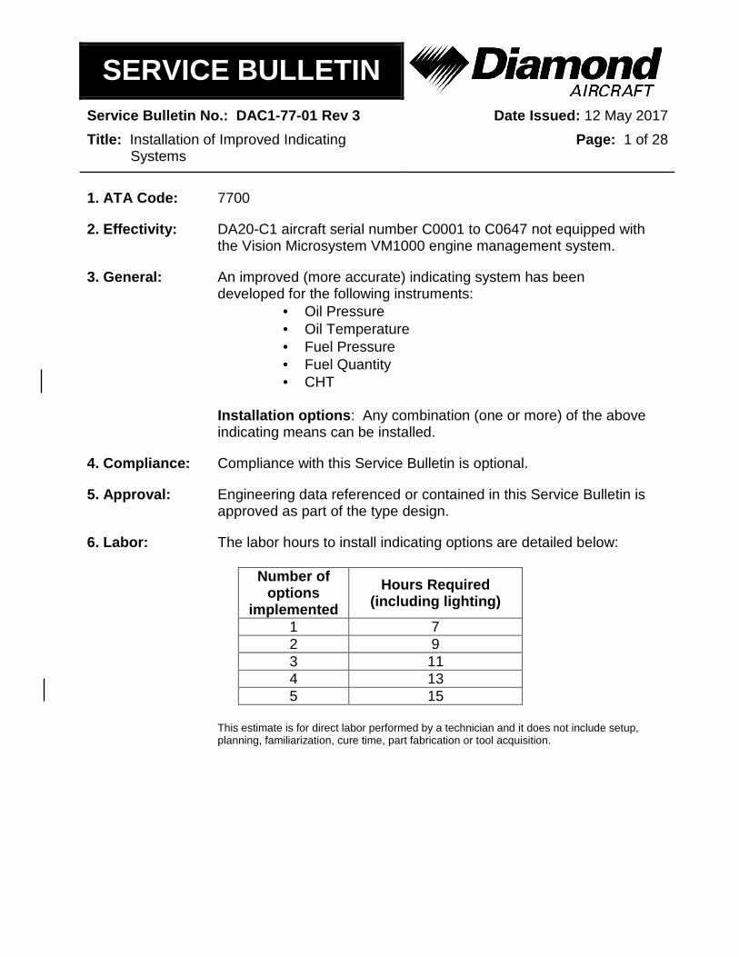
SERVICE BULLETIN
Service Bulletin No.: DAC1-77-01 Rev 3 Date Issued: 12 May 2017
Title: Installation of Improved Indicating Systems
Page: 1 of 28
1. ATA Code: 7700
2. Effectivity: DA20-C1 aircraft serial number C0001 to C0647 not equipped with the Vision Microsystem VM1000 engine management system.
3. General: An improved (more accurate) indicating system has been developed for the following instruments:
• Oil Pressure • Oil Temperature • Fuel Pressure • Fuel Quantity • CHT
Installation options: Any combination (one or more) of the above indicating means can be installed.
4. Compliance: Compliance with this Service Bulletin is optional.
5. Approval: Engineering data referenced or contained in this Service Bulletin is approved as part of the type design.
6. Labor: The labor hours to install indicating options are detailed below:
Number of options
implemented
Hours Required (including lighting)
1 7 2 9 3 11 4 13 5 15
This estimate is for direct labor performed by a technician and it does not include setup, planning, familiarization, cure time, part fabrication or tool acquisition.
SERVICE BULLETIN
Service Bulletin No.: DAC1-77-01 Rev 3 Date Issued: 12 May 2017
Title: Installation of Improved Indicating Systems
Page: 2 of 28
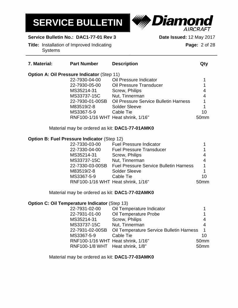
7. Material: Part Number Description Qty Option A: Oil Pressure Indicator (Step 11) 22-7930-04-00 Oil Pressure Indicator 1 22-7930-05-00 Oil Pressure Transducer 1 MS35214-31 Screw, Philips 4 MS33737-15C Nut, Tinnerman 4 22-7930-01-00SB Oil Pressure Service Bulletin Harness 1 M83519/2-8 Solder Sleeve 1 MS3367-5-9 Cable Tie 10 RNF100-1/16 WHT Heat shrink, 1/16” 50mm Material may be ordered as kit: DAC1-77-01AMK0 Option B: Fuel Pressure Indicator (Step 12) 22-7330-03-00 Fuel Pressure Indicator 1 22-7330-04-00 Fuel Pressure Transducer 1 MS35214-31 Screw, Philips 4 MS33737-15C Nut, Tinnerman 4 22-7330-03-00SB Fuel Pressure Service Bulletin Harness 1 M83519/2-8 Solder Sleeve 1 MS3367-5-9 Cable Tie 10 RNF100-1/16 WHT Heat shrink, 1/16” 50mm Material may be ordered as kit: DAC1-77-02AMK0 Option C: Oil Temperature Indicator (Step 13) 22-7931-02-00 Oil Temperature Indicator 1 22-7931-01-00 Oil Temperature Probe 1 MS35214-31 Screw, Philips 4 MS33737-15C Nut, Tinnerman 4 22-7931-02-00SB Oil Temperature Service Bulletin Harness 1 MS3367-5-9 Cable Tie 10 RNF100-1/16 WHT Heat shrink, 1/16” 50mm RNF100-1/8 WHT Heat shrink, 1/8” 50mm Material may be ordered as kit: DAC1-77-03AMK0

SERVICE BULLETIN
Service Bulletin No.: DAC1-77-01 Rev 3 Date Issued: 12 May 2017
Title: Installation of Improved Indicating Systems
Page: 3 of 28
Option D: Fuel Quantity Indicator (Step 14) 22-2840-01-00 Fuel Quantity Indicator 1 22-2840-02-00 Fuel Quantity Probe 1 MS35214-31 Screw, Philips 4 MS33737-15C Nut, Tinnerman 4 22-1131-00-13 Placard, Fuel Quantity 1 22-2840-01-00SB Fuel Quantity Service Bulletin Harness 1 AN525-10R20 Screw 5 NAS1149F0332P Washer 5 NAS1149F0363P Washer 5 EMS-A-CO Cable Tie base 1 MS3367-5-9 Cable Tie 10 RNF100-1/16 WHT Heat shrink, 1/16” 50mm 22-2550-13-00SB Baggage Floor Recess 1 Material may be ordered as kit: DAC1-77-04AMK0 Option E: CHT Indicator (Step 15) 22-7720-03-00 CHT Indicator 1 MS35214-31 Screw, Philips 4 MS33737-15C Nut, Tinnerman 4 22-7720-03-00SB CHT Service Bulletin Harness 1 MS3367-5-9 Cable Tie 10 RNF100-1/16 WHT Heat shrink, 1/16” 50mm RNF100-1/8 WHT Heat shrink, 1/8” 50mm Material may be ordered as kit: DAC1-77-05AMK0 NOTE: In addition, one Template is required for installation of indicators. 22-7700-12-00SB Template 1 NOTE: In addition, reverse panel installations with the SSD120-30A encoder mounted
on the support bracket require the following. 22-3935-80-02SB Encoder Mounting Plate 1 MS24693C24 Screw, Countersink 3 MS35206-216 Screw, Pan head 4

SERVICE BULLETIN
Service Bulletin No.: DAC1-77-01 Rev 3 Date Issued: 12 May 2017
Title: Installation of Improved Indicating Systems
Page: 4 of 28
NOTE: An optional lighting inverter may be ordered for indicator lighting. One inverter is required for installation of one or all options. Instrument lighting is a requirement for night VFR operation (Refer to AFM Section 2.13).
*10-700-14 Inverter 1 MS35206-228 Screw 2 MS21042-06 Nut, Self-Locking 2 NAS1149DN616H Washer 2 D-436-37 Splice, blue 1 22-7700-11-00SB Voltage Divider Assembly 1 1-480318-0 Connector, 2 socket 1 *the above Inverter includes the following: 60618-1 Contacts, pins 4 1-480426-0 Connector, 4 pos. 1 MB4A10 Cable tie base 1
8. Special Tools: 22-7700-12-00SB Template
9. References: DA20-C1 Aircraft Maintenance Manual, Document # DA201-C1 DA20-C1 Aircraft Flight Manual, Document # DA202-C1
10. General Instructions:
10.1 Disconnect the aircraft battery as per AMM Chapter 24-31-00
10.2 Remove instrument panel cover as per AMM Chapter 25-10-00
10.3 Pull the Battery Circuit breaker located on the right side of the instrument panel.
10.4 Place template (22-7700-12-00SB) on the top of existing engine indicating instruments, centre and tape in position.
10.4.1 Mark locations of screw positions for only the option(s) being installed.
10.4.2 Remove template

SERVICE BULLETIN
Service Bulletin No.: DAC1-77-01 Rev 3 Date Issued: 12 May 2017
Title: Installation of Improved Indicating Systems
Page: 5 of 28
10.5 Remove all 8 indicators as per AMM.
Oil Pressure / Oil Temperature Chapter 79-00-00 Fuel Pressure Chapter 73-00-00 Fuel Quantity Chapter 28-40-00 EGT / CHT Chapter 77-00-00 Voltmeter / Ammeter Chapter 24-31-00
10.6 Cover/protect area on inside of instrument panel, and related cockpit areas to ensure that metal filings/burrs from next operation is contained.
10.7 Drill two of the screw holes (3.6mm or 9/64”) previously marked.
10.8 Place the template back in position and secure with two #6 screws at previously drilled locations.
10.8.1 Drill remainder of the screw holes (3.6mm or 9/64”) one at a time and install hardware (#6 screw or Cleco) only for indicators being installed.
10.8.2 Using a drum sander or a high speed rotary grinder, open instrument panel hole(s) to the same hole diameter as on the template.
Remove shaded material of instrument being replaced. (Large hole: ø57.8mm) (Small holes: ø3.6mm)
Template

SERVICE BULLETIN
Service Bulletin No.: DAC1-77-01 Rev 3 Date Issued: 12 May 2017
Title: Installation of Improved Indicating Systems
Page: 6 of 28
10.9 Remove template.
10.10 De-burr any sharp edges.
10.11 Apply protective coating (Alodine) to bare metal.
10.12 Paint edges of instrument opening (optional) with matching paint color.
10.13 Clean area.
10.14 Re-install indicators not being replaced (Reference applicable AMM chapters listed in Step 10.5).
10.15 For reversed instrument panel installations with SSD120-30A encoder installed:
10.15.1 Remove encoder and mounting tray from support bracket stand-offs.
10.15.2 Install new encoder mounting plate (22-3935-80-02SB) using the
supplied screws (MS24693C24) onto stand-offs as per figure below.
Encoder plate (22-3935-80-02SB)
Screw (MS24693C24)

SERVICE BULLETIN
Service Bulletin No.: DAC1-77-01 Rev 3 Date Issued: 12 May 2017
Title: Installation of Improved Indicating Systems
Page: 7 of 28
10.15.3 Install encoder (without mounting tray) using supplied screws (MS35206-216).
NOTE: If static line is disconnected a leak check must be carried out.
Encoder (SSD120-30A)
Screw (MS35206-216)

SERVICE BULLETIN
Service Bulletin No.: DAC1-77-01 Rev 3 Date Issued: 12 May 2017
Title: Installation of Improved Indicating Systems
Page: 8 of 28
11. Option A: Oil Pressure Indicator/Transducer
11.1 Remove the following oil pressure indicator wires from the instrument panel harness.
Wire Code: From: To: 79303A20 Oil Pressure Indicator Oil Pressure Circuit Breaker
79310A20N Oil Pressure Indicator Ground Stud #1 79300A20 Oil Pressure Indicator Oil Pressure Transducer
11.2 Install new Oil Pressure Indicator (22-7930-04-00) into new larger instrument panel hole, using the supplied hardware (screw: MS35214-31, tinnerman nut: MS33737-15C).
11.3 Install Oil Pressure Indicator Harness (22-7930-01-00SB). Connect J7930-01 to Oil Pressure Indicator connector P7930-01.
Oil Pressure Indicator
Fasten connectors together and secure to existing harness.
Oil Pressure service bulletin harness
33705AA22
33725AA22N
33705A22
33725A22N

SERVICE BULLETIN
Service Bulletin No.: DAC1-77-01 Rev 3 Date Issued: 12 May 2017
Title: Installation of Improved Indicating Systems
Page: 9 of 28
11.4 Plug 22-7930-01-00SB harness wire 33705AA22 into existing lighting wire 33705A22 and wire 33725AA22N into existing lighting wire 33725A22N. See above.
11.5 Refer to Step 16 for Inverter installation.
11.6 Route 79303A22 wire to Oil Pressure circuit breaker and connect using existing hardware.
11.7 Route 79310A22N wire to Ground Stud #1 and connect using existing hardware.
11.8 Route triple twisted wire 79300A22 of harness through firewall and along existing harness to oil pressure transducer location.
11.9 Secure Oil Pressure Harness using supplied cable ties (MS3367-5-9).
11.10 Remove existing oil pressure transducer and install new oil pressure transducer (22-7930-05-00) in its place using loctite 545 (1-2 threads past finger tight).
Oil Pressure Transducer location

SERVICE BULLETIN
Service Bulletin No.: DAC1-77-01 Rev 3 Date Issued: 12 May 2017
Title: Installation of Improved Indicating Systems
Page: 10 of 28
11.11 Cut triple twisted harness wire 79300A22 to an appropriate length, strip shield back, apply solder sleeve (M83519/2-8) and terminate (60617-1) as shown below, with supplied connector (1-480424-0).
P7930-02 Pin Wire Code 1 79300A22BL 2 79300A22OR 3 79300A22WH 4 79300A22SH
11.12 Connect P7930-02 connector (transducer) with J7930-02 connector (harness) and secure using supplied cable ties (MS3367-5-9).

SERVICE BULLETIN
Service Bulletin No.: DAC1-77-01 Rev 3 Date Issued: 12 May 2017
Title: Installation of Improved Indicating Systems
Page: 11 of 28
12. Option B: Fuel Pressure Indicator/Transducer
12.1 Remove the following fuel pressure wires from instrument panel harness.
Wire Code: From: To: 73300A20 Fuel Pressure Indicator Fuel Pressure Circuit Breaker
73302A20N Fuel Pressure Indicator Ground Stud #6 73301A20 Fuel Pressure Indicator Fuel Pressure Transducer
12.2 Install new Fuel Pressure Indicator (22-7330-03-00) into new larger instrument panel hole, using the supplied hardware (screw: MS35214-31, nut: MS33737-15C).
12.3 Install Fuel Pressure Indicator Service Bulletin Harness (22-7330-03-00SB) connector J7330-01 to Fuel Pressure Indicator connector P7330-01.
Fuel Pressure Indicator
Plug connectors together and secure existing harness
33705A22
33725A22N
Fuel Pressure service bulletin harness
33725AA22N
33705AA22
SERVICE BULLETIN
Service Bulletin No.: DAC1-77-01 Rev 3 Date Issued: 12 May 2017
Title: Installation of Improved Indicating Systems
Page: 12 of 28
12.4 Plug service bulletin wire 33705AA22 into existing lighting wire 33705A22 and wire 33725AA22N into existing lighting wire 33725A22N.
12.5 Refer to Step 16 for Inverter installation.
12.6 Route 73300A22 wire to Fuel Pressure circuit breaker and connect using existing hardware.
12.7 Route 73302A22N wire to Ground Stud #6 and connect using existing hardware.
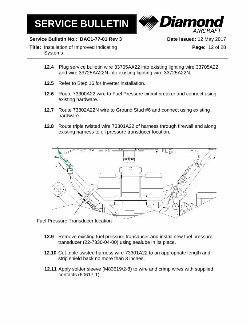
12.8 Route triple twisted wire 73301A22 of harness through firewall and along existing harness to oil pressure transducer location.
12.9 Remove existing fuel pressure transducer and install new fuel pressure transducer (22-7330-04-00) using sealube in its place.
12.10 Cut triple twisted harness wire 73301A22 to an appropriate length and strip shield back no more than 3 inches.
12.11 Apply solder sleeve (M83519/2-8) to wire and crimp wires with supplied contacts (60617-1).
Fuel Pressure Transducer location

SERVICE BULLETIN
Service Bulletin No.: DAC1-77-01 Rev 3 Date Issued: 12 May 2017
Title: Installation of Improved Indicating Systems
Page: 13 of 28
12.12 Plug wires into supplied connector (1-480424-0) with label (J7330-02).
J7330-02
Pin Wire Code 1 73301A22BL 2 73301A22OR 3 73301A22WH 4 73301A22SH
12.13 Connect P7330-02 connector (transducer) with J7330-02 connector (harness).
12.14 Secure wires with supplied cable ties (MS3367-5-9).
SERVICE BULLETIN
Service Bulletin No.: DAC1-77-01 Rev 3 Date Issued: 12 May 2017
Title: Installation of Improved Indicating Systems
Page: 14 of 28
13. Option C: Oil Temperature Indicator/Probe
13.1 Remove the following oil temperature wires from the instrument panel harness.
Wire Code: From: To: 79302A20 Oil Temperature Indicator Oil Temperature Circuit Breaker
79311A20N Oil Temperature Indicator Ground Stud #1 79301A20 Oil Temperature Indicator Oil Temperature Probe
13.2 Install new Oil Temperature Indicator (22-7931-02-00) into new larger instrument panel hole, using the supplied hardware (screw: MS35214-31, nut: MS33737-15C).
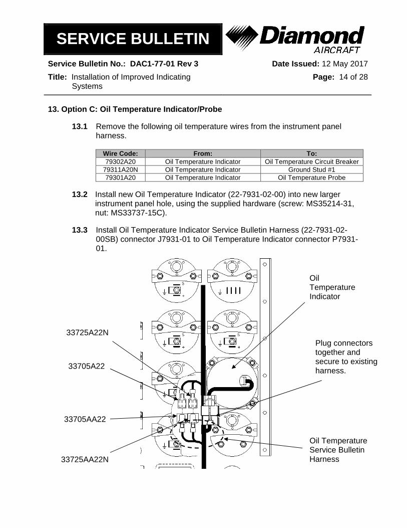
13.3 Install Oil Temperature Indicator Service Bulletin Harness (22-7931-02-00SB) connector J7931-01 to Oil Temperature Indicator connector P7931-01.
Oil Temperature Indicator
Plug connectors together and secure to existing harness. 33705A22
33725A22N
Oil Temperature Service Bulletin Harness 33725AA22N
33705AA22

SERVICE BULLETIN
Service Bulletin No.: DAC1-77-01 Rev 3 Date Issued: 12 May 2017
Title: Installation of Improved Indicating Systems
Page: 15 of 28
13.4 Plug service bulletin wire 33705AA22 into existing lighting wire 33705A22 and wire 33725AA22N into existing lighting wire 33725A22N.
13.5 Refer to Step 16 for Inverter installation.
13.6 Route 79302A22 wire to the Oil Temperature circuit breaker and connect using existing hardware.
13.7 Route 79311A22N wire to Ground Stud #1 and connect using existing hardware.
13.8 Route double twisted wire 79301A22 through firewall and along existing harness to oil temperature probe location.
13.9 Remove existing oil temperature probe and install new oil temperature probe (22-7931-01-00) in its place using loctite 545 (1-2 threads past finger tight).
13.10 Cut service bulletin harness wire (79301A22) to an appropriate length and strip shield back no more than 3 inches and apply heat shrink (RNF100-1/8 WHT).
13.11 Crimp wires with supplied contacts (60617-1).
Oil Temperature Probe location

SERVICE BULLETIN
Service Bulletin No.: DAC1-77-01 Rev 3 Date Issued: 12 May 2017
Title: Installation of Improved Indicating Systems
Page: 16 of 28
13.12 Plug wires into supplied connector (1-480318-0) with label (J7931-02).
J7931-02 Pin Wire Code 1 79301A22BL 2 79301A22WH
13.13 Connect P7931-02 connector (transducer) with J7931-02 connector (harness).
13.14 Secure wires with supplied cable ties (MS3367-5-9).

SERVICE BULLETIN
Service Bulletin No.: DAC1-77-01 Rev 3 Date Issued: 12 May 2017
Title: Installation of Improved Indicating Systems
Page: 17 of 28
14. Option D: Fuel Quantity Indicator/Probe
14.1 Remove seats in accordance with AMM Chapter 25-10-00.
14.2 Remove baggage floors in accordance with AMM Chapter 25-10-00.
14.3 Remove the following fuel quantity wires from the instrument panel harness.
Wire Code: From: To: 28400A20 Fuel Quantity Indicator Fuel Quantity Circuit Breaker
28403A20N Fuel Quantity Indicator Ground Stud #2 * 28401A20 Fuel Quantity Indicator Fuel Quantity Probe
* wire may include 2 ohm resistor. Resistor is also to be removed from harness.
14.4 Install new Fuel Quantity Indicator (22-2840-01-00) into new larger instrument panel hole, using the supplied hardware (screw: MS35214-31, nut: MS33737-15C).
14.5 Install supplied fuel quantity placard (22-1131-00-13) onto the bottom section of the face of the installed fuel quantity indicator.

SERVICE BULLETIN
Service Bulletin No.: DAC1-77-01 Rev 3 Date Issued: 12 May 2017
Title: Installation of Improved Indicating Systems
Page: 18 of 28
14.6 Install Fuel Quantity Indicator Service Bulletin Harness (22-2840-01-00SB) connector J2840-01 to Fuel Quantity Indicator connector P2840-01.
14.7 Plug service bulletin wire 33706AA22 into existing lighting wire 33706A22 and wire 33726AA22N into existing lighting wire 33726A22N.
14.8 Refer to Step 16 for Inverter installation.
14.9 Route 28400A22 wire to the Fuel Quantity circuit breaker and connect using existing hardware.
14.10 Route 28403A22N wire to Ground Stud #2 and connect using existing hardware.
Fuel Quantity Indicator
Plug connectors together and secure to existing harness.
33706AA22
33726AA22N
Fuel Quantity Service Bulletin Harness
33706A22
33726A22N

SERVICE BULLETIN
Service Bulletin No.: DAC1-77-01 Rev 3 Date Issued: 12 May 2017
Title: Installation of Improved Indicating Systems
Page: 19 of 28
14.11 Route triple twisted wire 28401A22 down through center console and along with the mic/phone jack wires.
14.12 Remove existing fuel probe and install new fuel probe (22-2840-02-00) using sealube with supplied hardware (screw: AN525-10R20, torque: 20.0 in x lbs). If the threads of screw bottom out, install supplied washer (NAS1149F0332P or NAS1149F0363P).
14.13 Install supplied cable tie base (EMS-A-CO) using DP100 adhesive or equivalent in the approximate location shown above.
14.14 Terminate fuel quantity wires as shown below and install into supplied connector (1-480424-0) with label (J2840-02).
J2840-02 Pin Wire Code 1 * JUMPER
2 * JUMPER
28401A22BL 3 28401A22WH 4 28401A22OR
* Jumper wire supplied with fuel quantity harness and is crimped together with 28401A22BL wire.
Fuel Probe
Cable tie base
Route through conduit

SERVICE BULLETIN
Service Bulletin No.: DAC1-77-01 Rev 3 Date Issued: 12 May 2017
Title: Installation of Improved Indicating Systems
Page: 20 of 28
14.15 Plug fuel quantity wire connector J2840-02 into fuel probe connector P2840-02 and secure with supplied cable tie (MS3367-5-9).
14.16 Temporarily install center baggage floor in position on top of fuel tank.
14.17 Mark location of fuel probe and remove baggage floor.
14.18 Cut a 3” (76mm) diameter hole in the centre baggage floor centered on fuel probe location.
14.19 Temporarily position recess panel 22-2550-13-00SB on top of centre baggage floor such that it covers 3-inch hole and mark location.
14.20 Remove paint from top surface of baggage floor where bonding is going to take place.
14.21 Prepare recess panel and baggage floor for bonding. Mask area beyond bonding area.
14.22 Bond using DP420 or similar structural adhesive. Clean excess adhesive.
14.23 Cure as per adhesive manufacturer instructions.
14.24 Paint touch up if required.
14.25 Perform foreign object detection (FOD) inspection.
14.26 Install baggage floor as per AMM Chapter 25-10-00.
14.27 Install seats as per AMM Chapter 25-10-00.
SERVICE BULLETIN
Service Bulletin No.: DAC1-77-01 Rev 3 Date Issued: 12 May 2017
Title: Installation of Improved Indicating Systems
Page: 21 of 28
15. Option E: CHT Indicator
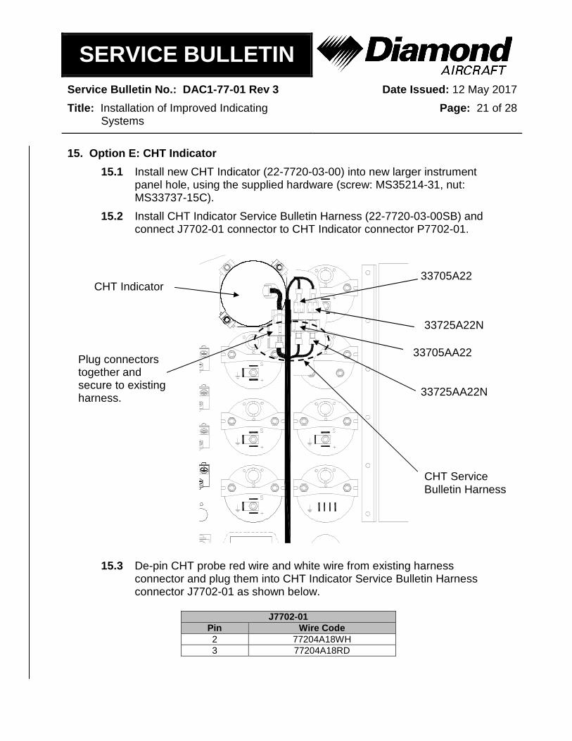
15.1 Install new CHT Indicator (22-7720-03-00) into new larger instrument panel hole, using the supplied hardware (screw: MS35214-31, nut: MS33737-15C).
15.2 Install CHT Indicator Service Bulletin Harness (22-7720-03-00SB) and connect J7702-01 connector to CHT Indicator connector P7702-01.
15.3 De-pin CHT probe red wire and white wire from existing harness connector and plug them into CHT Indicator Service Bulletin Harness connector J7702-01 as shown below.
J7702-01 Pin Wire Code 2 77204A18WH 3 77204A18RD
CHT Indicator
Plug connectors together and secure to existing harness.
33705A22
33725A22N
CHT Service Bulletin Harness
33725AA22N
33705AA22

SERVICE BULLETIN
Service Bulletin No.: DAC1-77-01 Rev 3 Date Issued: 12 May 2017
Title: Installation of Improved Indicating Systems
Page: 22 of 28
15.4 Plug service bulletin wire 33705AA22 into existing lighting wire 33705A22 and wire 33725AA22N into existing lighting wire 33725A22N.
15.5 Refer to Step 16 for Inverter installation.
15.6 Route 77205A22 wire to new EGT/OIL TEMP circuit breaker and connect using existing hardware.
15.7 Re-label circuit breaker as shown below, using a label maker or equivalent.
Existing Text New Text
EGT/ OIL TEMP
EGT/CHT/ OIL TEMP
15.8 Route 77206A22N wire to Ground Stud #7, or available ground stud, and connect using existing hardware.
15.9 Secure wires with supplied cable ties (MS3367-5-9).

SERVICE BULLETIN
Service Bulletin No.: DAC1-77-01 Rev 3 Date Issued: 12 May 2017
Title: Installation of Improved Indicating Systems
Page: 23 of 28
16. Lighting Inverter Installation
16.1 Install lighting inverter (10-700-14) inside instrument panel using inverter holes as mounting template.
NOTE: Position is only a reference location. Installer may choose other location (attach inverter to metal surface for heat sink).
16.2 Route service bulletin lighting wires to inverter and cut to appropriate length.
NOTE: If multiple indicator options are installed refer to schematic at the end of this service bulletin for lighting wiring instructions.
NOTE: Cap and stow unused lighting wires with supplied heat shrink (RNF100-1/16 WHT).

SERVICE BULLETIN
Service Bulletin No.: DAC1-77-01 Rev 3 Date Issued: 12 May 2017
Title: Installation of Improved Indicating Systems
Page: 24 of 28
16.3 Terminate lighting wires with supplied crimps and connect to plug, with supplied label. Install voltage divider assembly as shown.
J3310-05 PIN WIRE CODE
1 Wire from Voltage Divider Assembly 2 33725AA22N 3 33705A22 4 33704A22
Voltage Divider Assembly
Crimp wire with contact supplied with service bulletin harness (60617-1)
Connector (J3310-05) plugs into inverter. Connector supplied with service bulletin harness
Install wire to Ground Stud #8
Wires are part of service bulletin harness
Crimp wires with contacts supplied with service bulletin harness (60617-1)
Connector (1-480318-0) Label (3PS-250-2WT-2)

SERVICE BULLETIN
Service Bulletin No.: DAC1-77-01 Rev 3 Date Issued: 12 May 2017
Title: Installation of Improved Indicating Systems
Page: 25 of 28
Test Procedure:
16.4 Clean the work area and inspect for foreign objects.
16.5 Connect the aircraft battery as per ATA chapter 24-31-00 of the DA20-C1 AMM.
16.6 Push in Battery circuit breaker and turn Electrical Master switch to ON.
16.6.1 Confirm that the needle on the tested indicator(s) rises.
16.7 Run engine and verify the indicators display readings consistent with the AFM. Verify operation of lighting inverter.
16.8 Install the instrument panel cover as per ATA chapter 25-10-00 of the DA20-C1 AMM.
16.9 Make a log book entry that this Service Bulletin has been incorporated.
17. Weight and Balance: Make the following adjustments to weight and balance:
Items Removed Items Installed
Description Weight (lbs) Description Weight
(lbs) VDO Oil Pressure Indicator/transducer
0.5 UMA Oil Pressure Indicator/transducer/harness
0.82
VDO Fuel Pressure Indicator/transducer
0.5 UMA Fuel Pressure Indicator/transducer/harness
0.82
VDO Oil Temperature Indicator/probe 0.4
UMA Oil Temperature Indicator/probe/harness 0.75
VDO Fuel Quantity Indicator/probe 0.7
UMA Fuel Quantity Indicator/ Westach probe/harness 1.0
CHT Indicator 0.3 UMA CHT Indicator 0.82 n/a n/a UMA Lighting Inverter 0.20
18. Availability: Contact Diamond Aircraft Industries Inc.

SERVICE BULLETIN
Service Bulletin No.: DAC1-77-01 Rev 3 Date Issued: 12 May 2017
Title: Installation of Improved Indicating Systems
Page: 26 of 28
19. Electrical Load Data:
Items removed Items Installed Description Current (A) Description Current (A)
VDO Oil Pressure Indicator/transducer
0.016 UMA Oil Pressure Indicator/transducer
0.10 (+ 0.01 with lighting)
VDO Fuel Pressure Indicator/transducer
0.016 UMA Fuel Pressure Indicator/transducer
0.10 (+ 0.01 with lighting)
VDO Oil Temperature Indicator/probe
0.016 UMA Oil Temperature Indicator/probe
0.10 (+ 0.01 with lighting)
VDO Fuel Quantity Indicator/probe
0.016 UMA Fuel Quantity Indicator/ Westach probe
0.10 (+ 0.01 with lighting)
CHT Indicator n/a UMA CHT Indicator
0.10 (+ 0.01 with lighting)
n/a n/a UMA Lighting Inverter 0.05
20. Credit: None
To obtain satisfactory results, procedures specified in this service bulletin must be accomplished in accordance with accepted methods and current government regulations. Diamond Aircraft Industries Inc. cannot be responsible for the quality of work
performed in accomplishing the requirements of this service bulletin. Diamond Aircraft reserves the right to void continued warranty coverage in the area affected by this Service Bulletin if it is not incorporated. If you no longer own the aircraft to which this service bulletin applies, please forward it to the current owner and send the name of the current owner to Diamond Aircraft Industries, Inc.,
at the address below.
Diamond Aircraft Industries Inc. 1560 Crumlin Sideroad, London, Ontario, Canada N5V 1S2
Customer Support: Phone: (519) 457-4041 Fax: (519) 457-4045 Email: [email protected] Technical Publications: Phone: (519) 457-4030 Ext. 3173 Email: [email protected]
COPYRIGHT 2010

SERVICE BULLETIN
Service Bulletin No.: DAC1-77-01 Rev 3 Date Issued: 12 May 2017
Title: Installation of Improved Indicating Systems
Page: 27 of 28
SCHEMATIC 1: LIGHTING INVERTER
Voltage Divider Assembly (Optional installation)
When installing multiple indicator options the twisted lighting wires must be spliced together.
Only one of the power and ground wires are required to be plugged into the P3310-05 connector, irrespective of the number of options installed. Cap and stow unused power and ground wires.

SERVICE BULLETIN
Service Bulletin No.: DAC1-77-01 Rev 3 Date Issued: 12 May 2017
Title: Installation of Improved Indicating Systems
Page: 28 of 28
SCHEMATIC 2: INDICATING SYSTEM