Embed Size (px)
Citation preview
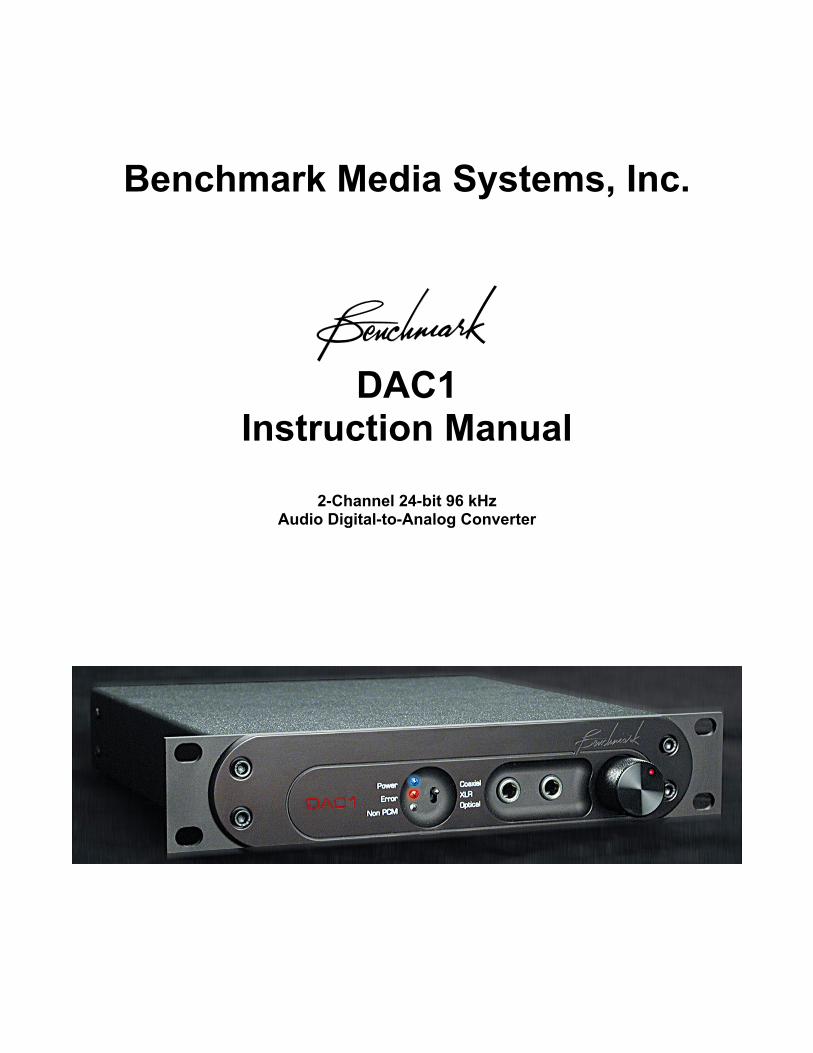
Benchmark Media Systems, Inc.
DAC1
Instruction Manual
2-Channel 24-bit 96 kHz Audio Digital-to-Analog Converter
Benchmark Media Systems, Inc.
DAC 1 - Manual - Rev B.doc Page 2 of 37 1/2/2003
Revision History: Revision Filename Date Author A DAC1 – Manual – Rev A. Doc 10/01/02 John Siau, Allen Burdick B DAC1 – Manual – Rev B. Doc 11/27/02 John Siau
Benchmark Media Systems, Inc.
DAC 1 - Manual - Rev B.doc Page 3 of 37 1/2/2003
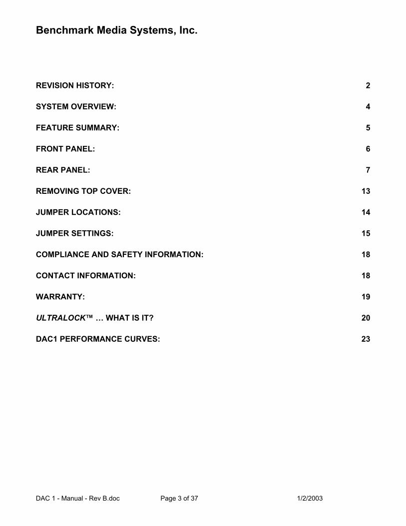
REVISION HISTORY: 2
SYSTEM OVERVIEW: 4
FEATURE SUMMARY: 5
FRONT PANEL: 6
REAR PANEL: 7
REMOVING TOP COVER: 13
JUMPER LOCATIONS: 14
JUMPER SETTINGS: 15
COMPLIANCE AND SAFETY INFORMATION: 18
CONTACT INFORMATION: 18
WARRANTY: 19
ULTRALOCK™ … WHAT IS IT? 20
DAC1 PERFORMANCE CURVES: 23
Benchmark Media Systems, Inc.
DAC 1 - Manual - Rev B.doc Page 4 of 37 1/2/2003
SYSTEM OVERVIEW: The DAC1 is a reference quality, 2-channel 96 kHz, 24-bit audio digital-to-analog converter featuring Benchmark’s UltraLock™ technology. The DAC1 is designed for maximum transparency and is well suited for critical playback in studio control rooms and in mastering rooms. A compact and rugged enclosure makes the DAC1 an excellent choice for location recording, broadcast facilities, and mobile trucks. The internal power supply supports all international voltages and has generous margins for over and under voltage conditions. Two ¼” headphone jacks are driven with Benchmark’s new HPA2™ headphone amplifier. The HPA2™ is a high-current amplifier that is capable of driving a wide variety of headphone loads while achieving less than 0.0003% distortion under load. The gain control sets the output level of the headphone jacks. It can also be used to control the output level of the balanced XLR and unbalanced RCA analog outputs. A rear panel switch selects Variable or Calibrated output levels. The DAC1 is designed to interface directly to power amps and powered studio monitors in order to provide the cleanest and shortest path from digital to monitor output. 20-dB pads are provided for interfacing to studio monitors having high input sensitivity. Three digital inputs (balanced XLR, coaxial, and optical) are provided and are selected from the front panel. All inputs accept either professional or consumer formats. The Benchmark UltraLock™ system is 100% jitter immune. The D/A conversion clock is totally isolated from the AES/EBU digital audio clocks in a topology that outperforms two-stage PLL designs. In fact, no jitter-induced artifacts can be detected using an Audio Precision System 2 Cascade test set. Measurement limits include detection of artifacts as low as -140 dBFS, application of jitter amplitudes as high as 12.75 unit intervals (UI) and application of jitter over a frequency range of 2 Hz to 200 kHz. Any AES/EBU signal that can be decoded by the AES/EBU receiver will be reproduced without the addition of any measurable jitter artifacts. In addition, the receiver IC has been selected for its ability to decode AES/EBU signals in the presence of very high levels of jitter. The DAC1 is designed to perform gracefully in the presence of errors and interruptions at the digital audio inputs. A soft mute circuit eliminates pops when a digital signal is applied. Power management circuitry controls the muting and resetting of all digital circuits upon removal and application of power. Audio is present at the outputs only 60 ms after applying a digital input signal and only 500 ms after applying power to the unit. The DAC1 is designed to avoid all unnecessary mute scenarios. Muting is only enabled upon loss of power, or when digital transmission errors occur. The DAC1 does not mute when the input data is all zeros. Consequently, no audio is lost when an audio transient follows full silence. Furthermore, the DAC1 SNR specifications represent the true system performance, not just the performance of an output mute circuit. The DAC1 will operate even when sample rate status bits are set incorrectly. Sample rate is determined by measuring the incoming signal. Lack of sample rate status bits or incorrectly set status bits will not cause loss of audio. The DAC1 is phase accurate between channels, and between other DAC1 boxes. A fully digital de-emphasis circuit supports 44.1, 48, 88.2 and 96 kHz and is automatically enabled in response to the pre-emphasis status bits of consumer format digital signals.
Benchmark Media Systems, Inc.
DAC 1 - Manual - Rev B.doc Page 5 of 37 1/2/2003
FEATURE SUMMARY: • XLR balanced, BNC coaxial, and Toslink optical digital inputs – front panel switch selectable • High level, +4 dBu balanced analog outputs, +29 dBu maximum output level • Jumper-selected 10, 20, or 30 dB pads on balanced outputs • -10 dBV unbalanced outputs, +21 dBu maximum output level • Two HPA2™ high-current, high-output ¼” headphone jacks • Front panel knob controls all analog outputs or just the headphone outputs (selected with rear-panel switch) • Analog output mute function on rear-panel switch • Preset output levels use multi-turn trimmers – one 10-turn trimmer per output, 20 dB Range, 2 dB/turn • Total jitter immunity with Benchmark, phase-accurate UltraLock™ technology • Two Error LEDs, (no digital input, non-PCM digital input) • Power Indicator LED • THD+N = -107 dB, 0.00045% @ -3 dBFS input, -105 dB, 0.00056% @ 0 dBFS input • Automatic de-emphasis in consumer mode at 44.1, 48, 88.2, or 96 kHz when pre-emphasis bit is set • Reliable and consistent performance under all operating conditions • 115V, 230V, 50-60 Hz international power supply with very wide operating range • Low radiation toroidal power transformer eliminates hum and line related interference • Low power consumption (8 Watts typical program, 16 Watts peak) • Meets FCC Class B and CE emissions requirements
Benchmark Media Systems, Inc.
DAC 1 - Manual - Rev B.doc Page 6 of 37 1/2/2003
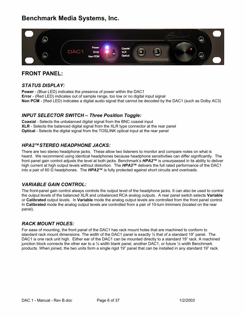
FRONT PANEL:
STATUS DISPLAY: Power - (Blue LED) indicates the presence of power within the DAC1 Error - (Red LED) indicates out of sample range, too low or no digital input signal Non PCM - (Red LED) indicates a digital audio signal that cannot be decoded by the DAC1 (such as Dolby AC3)
INPUT SELECTOR SWITCH – Three Position Toggle: Coaxial - Selects the unbalanced digital signal from the BNC coaxial input XLR - Selects the balanced digital signal from the XLR type connector at the rear panel Optical - Selects the digital signal from the TOSLINK optical input at the rear panel
HPA2™STEREO HEADPHONE JACKS: There are two stereo headphone jacks. These allow two listeners to monitor and compare notes on what is heard. We recommend using identical headphones because headphone sensitivities can differ significantly. The front panel gain control adjusts the level at both jacks. Benchmark’s HPA2™ is unsurpassed in its ability to deliver high current at high output levels without distortion. The HPA2™ delivers the full rated performance of the DAC1 into a pair of 60 Ω headphones. The HPA2™ is fully protected against short circuits and overloads.
VARIABLE GAIN CONTROL: The front-panel gain control always controls the output level of the headphone jacks. It can also be used to control the output levels of the balanced XLR and unbalanced RCA analog outputs. A rear panel switch selects Variable or Calibrated output levels. In Variable mode the analog output levels are controlled from the front panel control. In Calibrated mode the analog output levels are controlled from a pair of 10-turn trimmers (located on the rear panel).
RACK MOUNT HOLES: For ease of mounting, the front panel of the DAC1 has rack mount holes that are machined to conform to standard rack mount dimensions. The width of the DAC1 panel is exactly ½ that of a standard 19” panel. The DAC1 is one rack unit high. Either ear of the DAC1 can be mounted directly to a standard 19” rack. A machined junction block connects the other ear to a ½ width blank panel, another DAC1, or future ½ width Benchmark products. When joined, the two units form a single rigid 19” panel that can be installed in any standard 19” rack.
Benchmark Media Systems, Inc.
DAC 1 - Manual - Rev B.doc Page 7 of 37 1/2/2003
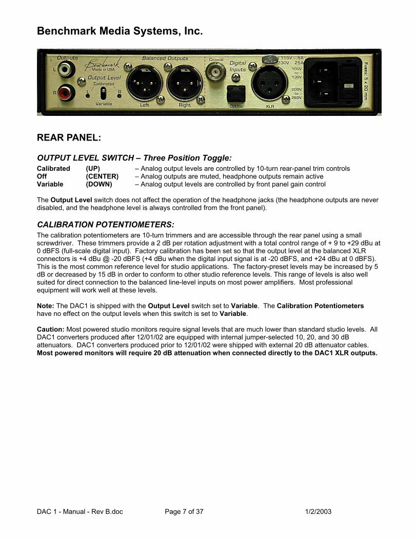
REAR PANEL:
OUTPUT LEVEL SWITCH – Three Position Toggle: Calibrated (UP) – Analog output levels are controlled by 10-turn rear-panel trim controls Off (CENTER) – Analog outputs are muted, headphone outputs remain active Variable (DOWN) – Analog output levels are controlled by front panel gain control The Output Level switch does not affect the operation of the headphone jacks (the headphone outputs are never disabled, and the headphone level is always controlled from the front panel).
CALIBRATION POTENTIOMETERS: The calibration potentiometers are 10-turn trimmers and are accessible through the rear panel using a small screwdriver. These trimmers provide a 2 dB per rotation adjustment with a total control range of + 9 to +29 dBu at 0 dBFS (full-scale digital input). Factory calibration has been set so that the output level at the balanced XLR connectors is +4 dBu @ -20 dBFS (+4 dBu when the digital input signal is at -20 dBFS, and +24 dBu at 0 dBFS). This is the most common reference level for studio applications. The factory-preset levels may be increased by 5 dB or decreased by 15 dB in order to conform to other studio reference levels. This range of levels is also well suited for direct connection to the balanced line-level inputs on most power amplifiers. Most professional equipment will work well at these levels. Note: The DAC1 is shipped with the Output Level switch set to Variable. The Calibration Potentiometers have no effect on the output levels when this switch is set to Variable. Caution: Most powered studio monitors require signal levels that are much lower than standard studio levels. All DAC1 converters produced after 12/01/02 are equipped with internal jumper-selected 10, 20, and 30 dB attenuators. DAC1 converters produced prior to 12/01/02 were shipped with external 20 dB attenuator cables. Most powered monitors will require 20 dB attenuation when connected directly to the DAC1 XLR outputs.
Benchmark Media Systems, Inc.
DAC 1 - Manual - Rev B.doc Page 8 of 37 1/2/2003
ANALOG OUTPUTS:
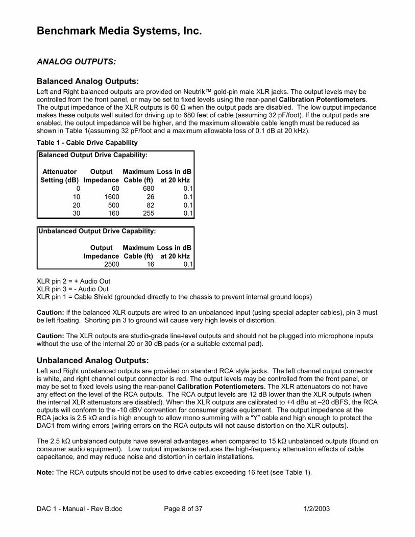
Balanced Analog Outputs: Left and Right balanced outputs are provided on Neutrik™ gold-pin male XLR jacks. The output levels may be controlled from the front panel, or may be set to fixed levels using the rear-panel Calibration Potentiometers. The output impedance of the XLR outputs is 60 Ω when the output pads are disabled. The low output impedance makes these outputs well suited for driving up to 680 feet of cable (assuming 32 pF/foot). If the output pads are enabled, the output impedance will be higher, and the maximum allowable cable length must be reduced as shown in Table 1(assuming 32 pF/foot and a maximum allowable loss of 0.1 dB at 20 kHz).
Table 1 - Cable Drive Capability
Balanced Output Drive Capability:
Attenuator Output Maximum Loss in dBSetting (dB) Impedance Cable (ft) at 20 kHz
0 60 680 0.110 1600 26 0.120 500 82 0.130 160 255 0.1
Unbalanced Output Drive Capability:
Output Maximum Loss in dBImpedance Cable (ft) at 20 kHz
2500 16 0.1 XLR pin 2 = + Audio Out XLR pin 3 = - Audio Out XLR pin 1 = Cable Shield (grounded directly to the chassis to prevent internal ground loops) Caution: If the balanced XLR outputs are wired to an unbalanced input (using special adapter cables), pin 3 must be left floating. Shorting pin 3 to ground will cause very high levels of distortion. Caution: The XLR outputs are studio-grade line-level outputs and should not be plugged into microphone inputs without the use of the internal 20 or 30 dB pads (or a suitable external pad).
Unbalanced Analog Outputs: Left and Right unbalanced outputs are provided on standard RCA style jacks. The left channel output connector is white, and right channel output connector is red. The output levels may be controlled from the front panel, or may be set to fixed levels using the rear-panel Calibration Potentiometers. The XLR attenuators do not have any effect on the level of the RCA outputs. The RCA output levels are 12 dB lower than the XLR outputs (when the internal XLR attenuators are disabled). When the XLR outputs are calibrated to +4 dBu at –20 dBFS, the RCA outputs will conform to the -10 dBV convention for consumer grade equipment. The output impedance at the RCA jacks is 2.5 kΩ and is high enough to allow mono summing with a “Y” cable and high enough to protect the DAC1 from wiring errors (wiring errors on the RCA outputs will not cause distortion on the XLR outputs). The 2.5 kΩ unbalanced outputs have several advantages when compared to 15 kΩ unbalanced outputs (found on consumer audio equipment). Low output impedance reduces the high-frequency attenuation effects of cable capacitance, and may reduce noise and distortion in certain installations. Note: The RCA outputs should not be used to drive cables exceeding 16 feet (see Table 1).
Benchmark Media Systems, Inc.
DAC 1 - Manual - Rev B.doc Page 9 of 37 1/2/2003
DIGITAL INPUTS: There are three digital inputs on the DAC1. These inputs are selected from a front panel toggle switch. All of the inputs can decode AES/EBU and S/PDIF input signals in either professional or consumer formats. The DAC1 will not decode AC3 signals. A red Non PCM Error LED will illuminate when AC3 or other non-PCM input signals are connected to the selected digital input. Internal jumpers can be used to disable the front panel selector switch. These jumpers allow the permanent selection of any one of the three digital inputs. This feature is useful for applications where the DAC1 has a dedicated function in a critical audio path.
XLR Digital Input: This input uses a gold-pin Neutrik™ female XLR connector. The input is balanced and has a 110 Ω input impedance. This input is DC isolated, transformer coupled, current limited, and diode protected. It is designed to accept standard 4 Vpp AES signals, and will work reliably with levels as low as 300 millivolts. Receive errors will occur (and the DAC1 will mute) when the peak-to-peak input voltage is less than about 160 millivolts.
Coaxial Digital Input: The coaxial input uses a female BNC connector that is securely mounted directly to the rear panel. The input impedance is 75 Ω. This input is DC isolated, transformer coupled, current limited, and diode protected. Like the other digital inputs, this input accepts AES/EBU or S/PDIF digital audio formats. The BNC connector is specified by the AES3-id and SMPTE 276M standards for 75 Ω 1 Vpp digital audio signals and is commonly used in video production facilities. IEC 609588-3 specifies the use of an RCA type connector for 75 Ω 0.5 Vpp consumer-format digital audio signals (commonly known as S/PDIF). The coaxial input on the DAC1 is designed to accept either type of signal. We have chosen to use a BNC connector because of its superior reliability. The DAC1 comes with a BNC-to-RCA adapter to allow easy interface with consumer equipment. The BNC input has a 75 Ω internal termination that may be disabled by removing a jumper. This termination is required for normal operation, but may be removed if the user wishes to loop a single coaxial feed through several other pieces of equipment. A 75 Ω termination must be applied at the last device on the loop, and there should be a combined total of less than 6 feet of cable between the first and last receive device.
Optical Input: The optical input connector is manufactured by Toshiba and is commonly known as a Toslink connector. Toslink optical connections work well at sample rates up to 96 kHz but may be unreliable or non-functional at higher sample rates (such as 192 kHz). We suggest using either the XLR or coaxial digital inputs at sample rates above 96 kHz.
AC POWER INPUT CONNECTOR AND FUSE HOLDER: The AC power input uses a standard IEC type connector. One USA compatible power cord is included with the DAC1. IEC style power cords in country specific configurations are generally available in your locality. If you are unable to purchase a proper power cord for the country in which you live, we may, for an additional charge, be able to locate one for you. Please contact the sales department at Benchmark Media Systems for further information. The fuse holder is built into a drawer next to the IEC power connector. The drawer requires two 7 X 20 mm fuses. The drawer includes a voltage selection switch with two settings (115 V and 230 V). The fuse rating for the 115-volt setting is 0.50 Amp. The rating for the 230-volt setting is 0.25 Amp. The AC input has a very wide input voltage range and can operate over a frequency range of 50 to 60 Hz. At “115V”, the DAC1 will operate normally over a range of 90 to 140 VAC. At “230V” the DAC1 will operate normally over a range of 175 to 285 VAC. Caution: Always install the correct fuses when changing the voltage setting. Always insure that the voltage setting is correct for your locality.
Benchmark Media Systems, Inc.
DAC 1 - Manual - Rev B.doc Page 10 of 37 1/2/2003
SPECIFICATIONS:
DIGITAL INPUTS: Number of Digital Inputs (switch selected): 3, (XLR, Coaxial, Toslink) Number of Audio Channels: 2 Input Sample Frequency Range: 28 to 195 kHz Maximum Input Word Length 24-bits Digital Input Impedance on XLR input: 110 Ω Digital Input Impedance on Coaxial input (Jumper Selected): 75 Ω or Hi-Z (Bridging) Transformer Coupled Digital Inputs: Yes DC Blocking Capacitors on Digital Inputs: Yes Transient and Over-Voltage Protection on Digital Inputs: Yes Minimum Digital Input Level: 300 mVpp on XLR, 150 mVpp on Coaxial Jitter Tolerance (With no Measurable Change in Performance): >12.75 UI sine, 100Hz-10 kHz
> 3.5 UI sine at 20 kHz > 1.2 UI sine at 40 kHz > 0.4 UI sine at 80 kHz > 0.29 UI sine at 90 kHz > 0.25 UI sine above 160 kHz
Jitter Attenuation Method: Benchmark UltraLock™
BALANCED ANALOG OUTPUTS: Number of Balanced Analog Outputs: 2 Output Connector: Gold-Pin Neutrik™ male XLR Output Impedance: 60 Ω Output Level Calibration Controls: 10-turn trimmers (1 per output) Calibration Adjustability: 2 dB / turn Output Level Range (at 0 dBFS) In “Calibrated” Mode: +9 dBu to +29 dBu (Attenuator off) -1 dBu to +19 dBu (Attenuator = 10 dB) -11 dBu to +9 dBu (Attenuator = 20 dB) -21 dBu to -1 dBu (Attenuator = 30 dB) Output Level Range (at 0 dBFS) In “Variable” Mode: Off to +29 dBu (Attenuator off) Off to +19 dBu (Attenuator = 10 dB) Off to +9 dBu (Attenuator = 20 dB) Off to -1 dBu (Attenuator = 30 dB) Output Level Variation with Sample Rate (44.1 kHz vs. 96 kHz): < +/- 0.006 dB
UNBALANCED ANALOG OUTPUTS: Number of Balanced Analog Outputs: 2 Output Connector: RCA Output Impedance: 2.5 kΩ Output Level Calibration Controls: Shared with Balanced Outputs Output Level Range (at 0 dBFS) In “Calibrated” Mode: -3 dBu to +17 dBu Output Level Range (at 0 dBFS) In “Variable” Mode: Off to +17 dBu Calibration Adjustability: 2 dB / turn Output Level Variation with Sample Rate (44.1 kHz vs. 96 kHz): < +/- 0.006 dB
HPA2™ HEADPHONE OUTPUTS: Number of Headphone Outputs: 2 Output Connector: ¼” TRS Output Impedance: 0 Ω Output Level Control: Stereo Control on Front Panel Output Level Range (at 0 dBFS) into 60 Ω Load: Off to +21 dBu
Benchmark Media Systems, Inc.
DAC 1 - Manual - Rev B.doc Page 11 of 37 1/2/2003
AUDIO PERFORMANCE: Fs = 44.1 to 96 kHz, 20 to 20 kHz BW, 1 kHz test tone, 0 dBFS = +24 dBu (unless noted): SNR – A-Weighted, (0 dBFS = +20 to +29 dBu): 116 dB SNR – Unweighted, (0 dBFS = +20 to +29 dBu): 114 dB SNR – A-Weighted at low gain, (0 dBFS = +9 to +18 dBu): 114 dB
THD+N, 1 kHz at 0 dBFS: -105 dBFS, -105 dB, 0.00056% THD+N, 1 kHz at –1 dBFS: -107 dBFS, -106 dB, 0.00050% THD+N, 1 kHz at –3 dBFS: -110 dBFS, -107 dB, 0.00045% THD+N, 20 to 20 kHz test tone at –3 dBFS: -110 dBFS, -107 dB, 0.00045% Frequency Response at Fs=48 kHz: +/- 0.1 dB (20 to 20 kHz) -0.02 dB at 10 Hz -0.20 dB at 20 kHz Frequency Response at Fs=96 kHz: +/- 0.1 dB (20 to 20 kHz) -0.02 dB at 10 Hz -0.20 dB at 20 kHz -0.85 dB at 40 kHz -2.5 dB at 45 kHz Crosstalk: -100 dB at 20 kHz -125 dB at 1 kHz -130 dB at 20 Hz Maximum Amplitude of Jitter Induced Sidebands: < -141 dB (10 kHz 0 dBFS test tone, 12.75 UI sinusoidal jitter at 1 kHz) Maximum Amplitude of Spurious Tones with 0 dBFS test signal: < -126 dB Maximum Amplitude of Idle Tones: < -128 dB Maximum Amplitude of AC line related Hum & Noise: < -126 dB Interchannel Differential Phase (Stereo Pair): +/- 0.5 degrees at 20 kHz Interchannel Differential Phase (Between DAC1 Units): +/- 0.5 degrees at 20 kHz Delay (Digital Input to Analog Output): 1.01 mS + (48/Fs) 2.10 ms at 44.1 kHz
2.01 ms at 48 kHz 1.55 ms at 88.2 kHz 1.51 ms at 96 kHz
Maximum Lock Time – after Fs change: 100 mS Soft Mute Ramp Up/Down Time: 10 mS Mute on Receive Error: Yes Mute on Lock Error: Yes Mute on Idle Channel: No 50/15 uS De-Emphasis Enable: Automatic in Consumer Mode De-Emphasis Method: Digital IIR De-Emphasis Supported at: Fs = 32, 44.1, 48, and 96 kHz
Benchmark Media Systems, Inc.
DAC 1 - Manual - Rev B.doc Page 12 of 37 1/2/2003
GROUP DELAY (LATENCY): Delay from digital input to analog output is a function of sample rate: 2.72 ms at 28 kHz 2.51 ms at 32 kHz 2.10 ms at 44.1 kHz 2.01 ms at 48 kHz 1.55 ms at 88.2 kHz 1.51 ms at 96 kHz 1.45 ms at 108 kHz The delay can be calculated using the following formula: Delay = 1.01 mS + (48/Fs) Where Fs = the sample rate in Hz.
LED STATUS INDICATORS: LED Location: Front Panel Power: (AC power is connected and +5 V supply is operating) 1 (Blue) Error: (Error on the active digital input) 1 (Red) Non PCM: (Non-compatible digital audio format on active input) 1 (Red)
AC POWER REQUIREMENTS: 50-60 Hz 8 Watts Idle 8 Watts Typical Program 16 Watts Maximum Fuses (2 required) – 7 X 20 mm 0.5 Amp – 100 V to 130 VAC 0.25 Amp – 200 V to 260 VAC Input Operating Voltage Range – VAC RMS 115 V setting – 90 V min, 140 V max 230 V setting – 175 V min, 285 V max
DIMENSIONS: ½ Rack Wide, 1 RU High 8.5” (216 mm) Depth behind front panel 9.33” (237 mm) Overall depth including connectors but without power cord or BNC-to-RCA adapter. 9.5” (249 mm) Wide 1.725” (44.5 mm) High
WEIGHT: DAC1 only: 3.5 lb. DAC1 with power cord, BNC-to-RCA adapter, and manual: 4.5 lb. Rack mount kit (blank panel, junction block, and rack-mount screws): 0.32 lb. Shipping weight: 7 lb.
Benchmark Media Systems, Inc.
DAC 1 - Manual - Rev B.doc Page 13 of 37 1/2/2003
REMOVING TOP COVER: The DAC1 has a removable cover. This cover provides access to the jumper settings on the PCB. The DAC1 contains static sensitive components and should only be opened by qualified technicians. Static discharge may cause component failures, may affect the long-term reliability, or may degrade the audio performance. Use a static control wrist strap when changing jumper settings. Caution: • Disconnect AC power by unplugging the power cord at the back of the DAC1. • Remove only the 8 screws holding the cover (4 on each side). • Do not remove any screws on front or rear panels. • Never remove the power entry safety cover in the rear corner of the DAC1. • Use a static control wrist strap when changing jumper settings.
Benchmark Media Systems, Inc.
DAC 1 - Manual - Rev B.doc Page 14 of 37 1/2/2003
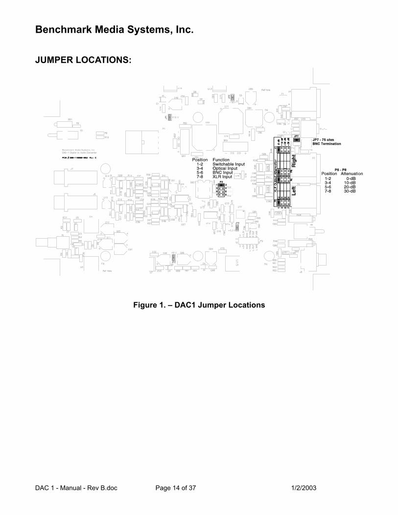
JUMPER LOCATIONS:
Figure 1. – DAC1 Jumper Locations
Benchmark Media Systems, Inc.
DAC 1 - Manual - Rev B.doc Page 15 of 37 1/2/2003
JUMPER SETTINGS: Jumpers are provided for special applications. A 2-pin jumper plug at header P2 can be moved in order to disable the front-panel input selection switch. A jumper at JP7 can be removed to disable the 75 Ω termination on the coaxial digital input. Four 8-pin headers (P5, P6, P7, and P8) allow selection of the output level at the XLR jacks. Caution: Do not change any jumpers other than P2, P5, P6, P7, P8, and JP7. All other jumpers are for test purposes only. Jumpers must always be installed at JP1, JP2, JP5, and JP6 (power supply enable jumpers). Jumpers should not be installed on header P9.
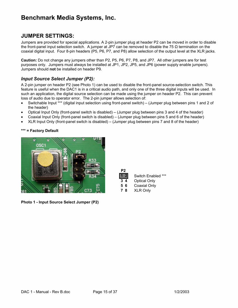
Input Source Select Jumper (P2): A 2-pin jumper on header P2 (see Photo 1) can be used to disable the front-panel source-selection switch. This feature is useful when the DAC1 is in a critical audio path, and only one of the three digital inputs will be used. In such an application, the digital source selection can be made using the jumper on header P2. This can prevent loss of audio due to operator error. The 2-pin jumper allows selection of: • Switchable Input *** (digital input selection using front-panel switch) – (Jumper plug between pins 1 and 2 of
the header) • Optical Input Only (front-panel switch is disabled) – (Jumper plug between pins 3 and 4 of the header) • Coaxial Input Only (front-panel switch is disabled) – (Jumper plug between pins 5 and 6 of the header) • XLR Input Only (front-panel switch is disabled) – (Jumper plug between pins 7 and 8 of the header) *** = Factory Default
P21 23 45 67 8
Switch Enabled ***Optical OnlyCoaxial OnlyXLR Only
Photo 1 - Input Source Select Jumper (P2)
Benchmark Media Systems, Inc.
DAC 1 - Manual - Rev B.doc Page 16 of 37 1/2/2003
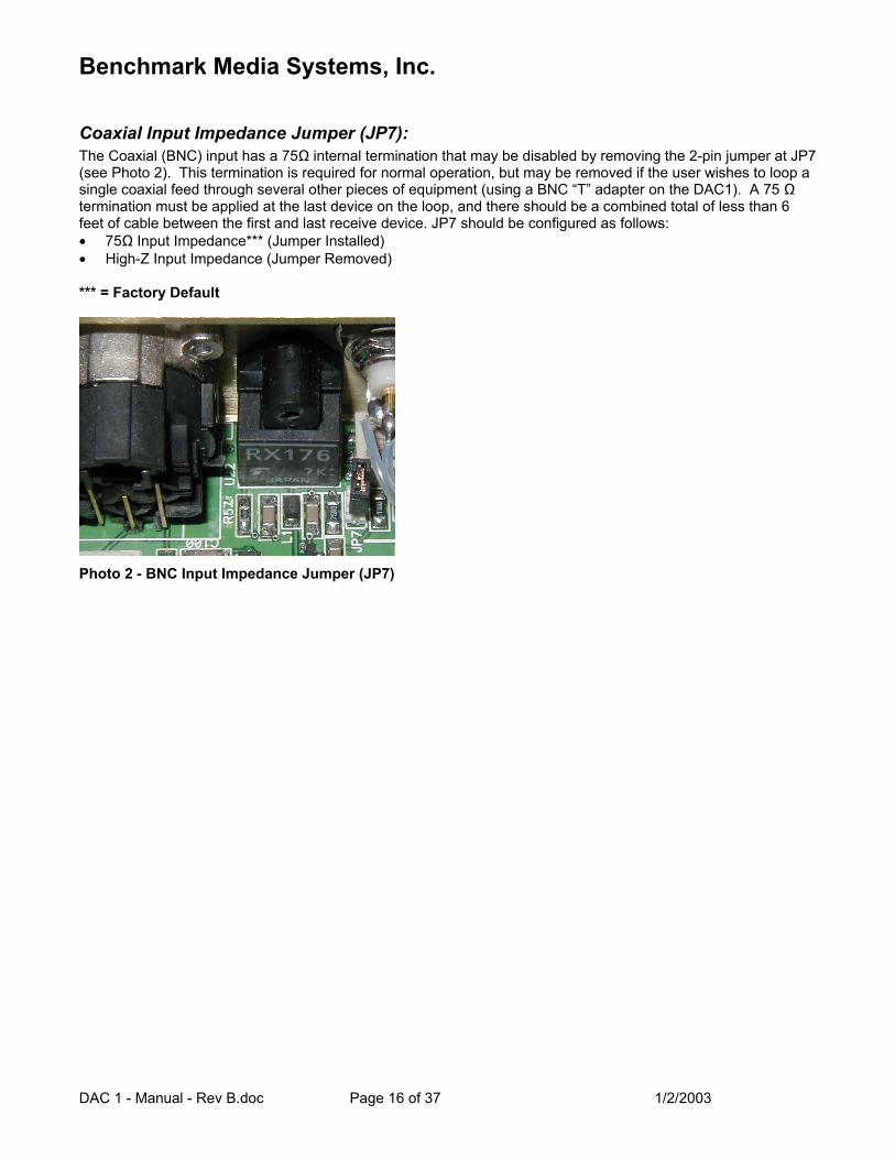
Coaxial Input Impedance Jumper (JP7): The Coaxial (BNC) input has a 75Ω internal termination that may be disabled by removing the 2-pin jumper at JP7 (see Photo 2). This termination is required for normal operation, but may be removed if the user wishes to loop a single coaxial feed through several other pieces of equipment (using a BNC “T” adapter on the DAC1). A 75 Ω termination must be applied at the last device on the loop, and there should be a combined total of less than 6 feet of cable between the first and last receive device. JP7 should be configured as follows: • 75Ω Input Impedance*** (Jumper Installed) • High-Z Input Impedance (Jumper Removed) *** = Factory Default
Photo 2 - BNC Input Impedance Jumper (JP7)
Benchmark Media Systems, Inc.
DAC 1 - Manual - Rev B.doc Page 17 of 37 1/2/2003
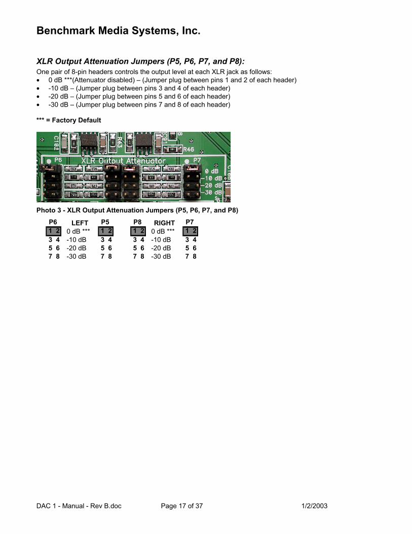
XLR Output Attenuation Jumpers (P5, P6, P7, and P8): One pair of 8-pin headers controls the output level at each XLR jack as follows: • 0 dB ***(Attenuator disabled) – (Jumper plug between pins 1 and 2 of each header) • -10 dB – (Jumper plug between pins 3 and 4 of each header) • -20 dB – (Jumper plug between pins 5 and 6 of each header) • -30 dB – (Jumper plug between pins 7 and 8 of each header) *** = Factory Default
Photo 3 - XLR Output Attenuation Jumpers (P5, P6, P7, and P8)
P61 23 45 67 8
LEFT0 dB ***-10 dB-20 dB-30 dB
P51 23 45 67 8
P81 23 45 67 8
RIGHT0 dB ***-10 dB-20 dB-30 dB
P71 23 45 67 8
Benchmark Media Systems, Inc.
DAC 1 - Manual - Rev B.doc Page 18 of 37 1/2/2003
COMPLIANCE and SAFETY INFORMATION:
FCC Class B Compliance: This device complies with part 15 of the FCC Rules. Operation is subject to the following two conditions: (1) This device may not cause harmful interference, and (2) This device must accept any interference received, including interference that may cause undesired operation.
Safety Information: Do NOT service or repair this product unless properly qualified. Only a qualified technician should perform repairs. For continued fire hazard protection, fuses should be replaced ONLY with the exact value and type as indicated on the rear panel. Do NOT substitute parts or make any modifications without the written approval of Benchmark Media Systems, Inc. Doing so may create safety hazards and void the warranty.
CONTACT INFORMATION: Benchmark Media Systems, Inc. 5925 Court Street Road Syracuse, NY 13206-1707 USA (315) 437-6300 www.benchmarkmedia.com

Benchmark Media Systems, Inc.
DAC 1 - Manual - Rev B.doc Page 19 of 37 1/2/2003
WARRANTY:
The Benchmark 5 Year Warranty Benchmark Media Systems, Inc. warrants its products to be free from defects in material and workmanship under normal use and service for a period of five years from the date of delivery. This warranty extends only to the original purchaser. This warranty does not apply to fuses, lamps, batteries, or any products or parts that have been subjected to misuse, neglect, accident, or abnormal operating conditions. In the event of failure of a product under this warranty, Benchmark Media Systems, Inc. will repair, at no charge, the product returned to its factory. Benchmark Media Systems, Inc. may, at its option, replace the product in lieu of repair. If the failure has been caused by misuse, neglect, accident or abnormal operating conditions, repairs will be billed at the normal shop rate. In such cases, an estimate will be submitted before work is started, if requested by the customer. The foregoing warranty is in lieu of all other warranties, expressed or implied, including but not limited to any implied warranty of merchantability, fitness or adequacy for any particular purpose or use. Benchmark Media Systems, Inc. shall not be liable for any special, incidental, or consequential damages. This limited warranty gives the consumer-owner specific legal rights, and there may also be other rights that vary from state to state. A return authorization is required when sending products for repair. They must be shipped to Benchmark Media Systems, Inc. prepaid and preferably in their original shipping carton. A letter should be included addressed to the customer service department, giving full details of the difficulty.
Benchmark Media Systems, Inc.
DAC 1 - Manual - Rev B.doc Page 20 of 37 1/2/2003
UltraLock™ … What is It? Accurate 24-bit audio conversion requires a very low-jitter conversion clock. Jitter can very easily turn a 24-bit converter into a 16-bit converter (or worse). There is no point in buying a 24-bit converter if clock jitter has not been adequately addressed. Jitter is present on every digital audio interface. This type of jitter is known as “interface jitter” and it is present even in the most carefully designed audio systems. Interface jitter accumulates as digital signals travel down a cable and from one digital device to the next. If we measure interface jitter in a typical system we will find that it 10 to 10,000 times higher than the level required for accurate 24-bit conversion. Fortunately, this interface jitter has absolutely no effect on the audio unless it influences the conversion clock in an analog-to-digital converter (ADC) or in a digital-to-analog converter (DAC). Many converters use a single-stage Phase Lock Loop (PLL) circuit to derive their conversion clocks from AES/EBU, Wordclock, or Superclock reference signals. Single-stage PLL circuits provide some jitter attenuation above 5 kHz but none below 5 kHz. Unfortunately, digital audio signals often have their strongest jitter components at 2 kHz. Consequently, these converters can achieve their rated performance only when driven from very low jitter sources and through very short cables. It is highly unlikely that any converter with a single-stage PLL can achieve better than 16-bits of performance in a typical installation. Specified performance may be severely degraded in most installations. Better converters usually use a two-stage PLL circuit to filter out more of the interface jitter. In theory, a two-stage PLL can remove enough of the jitter to achieve accurate 24-bit conversion (and some do). However, two-stage PLL circuits are not all created equal. Many two-stage PLLs do not remove enough of the low-frequency jitter. In addition, two-stage PLL circuits often require several seconds to lock to an incoming signal. Finally, a two-stage PLL may fail to lock when jitter is too high, or when the reference sample frequency has drifted. UltraLock™ converters exceed the jitter performance of two-stage PLL converters, and are free from the slow-lock and no-lock problems that can plague two-stage PLL designs. UltraLock™ converters are 100% immune to interface jitter under all operating conditions. No jitter-induced artifacts can be detected using an Audio Precision System 2 Cascade test set. Measurement limits include detection of artifacts as low as –140 dBFS, application of jitter amplitudes as high as 12.75 UI, and application of jitter over a frequency range of 2 Hz to 200 kHz. Any AES/EBU signal that can be decoded by the AES/EBU receiver will be reproduced without the addition of any measurable jitter artifacts. The DAC1, DAC-104 and the ADC-104 employ Benchmark’s new UltraLock™ technology to eliminate all jitter-induced performance problems. UltraLock™ technology isolates the conversion clock from the digital audio interface clock. Jitter on a DAC digital audio input, or an ADC reference input can never have any measurable effect on the conversion clock of an UltraLock™ converter. In an UltraLock™ converter, the conversion clock is never phase-locked to a reference clock. Instead the converter oversampling-ratio is varied with extremely high precision to achieve the proper phase relationship to the reference clock. Interface jitter cannot degrade the quality of the audio conversion. Specified performance is consistent and repeatable in any installation! How does conversion clock jitter degrade converter performance? Problem #1: Jitter phase modulates the audio signal. This modulation creates sidebands (unwanted tones) above and below every tone in the audio signal. Worse yet, these sidebands are often widely separated from the tones in the original signal. Jitter-induced sidebands are not musical in nature because they are not harmonically related to the original audio. Furthermore, these sidebands are poorly masked (easy to hear) because they can be widely separated above and below the frequencies of the original audio tones. In many ways, jitter induced distortion resembles intermodulation distortion (IMD). Like IMD, jitter induced distortion is much more audible than harmonic distortion, and more audible than THD measurements would suggest.
Benchmark Media Systems, Inc.
DAC 1 - Manual - Rev B.doc Page 21 of 37 1/2/2003
Jitter creates “new audio” that is not harmonically related to the original audio signal. This “new audio” is unexpected and unwanted. It can cause a loss of imaging, and can add a low and mid frequency “muddiness” that was not in the original audio. Jitter induced sidebands can be measured using an FFT analyzer. Problem #2: Jitter can severely degrade the anti-alias filters in an oversampling converter. This is a little known but easily measurable effect. Most audio converters operate at high oversampling ratios. This allows the use of high-performance digital anti-alias filters in place of the relatively poor performing analog anti-alias filters. In theory, digital anti-alias filters can have extremely sharp cutoff characteristics, and very few negative effects on the in-band audio signal. Digital anti-alias filters are usually designed to achieve at least 100 dB of stop-band attenuation. But, digital filters are designed using the mathematical assumption that the time interval between samples is a constant. Unfortunately, sample clock jitter in an ADC or DAC varies the effective time interval between samples. This variation alters the performance of these carefully designed filters. Small amounts of jitter can severely degrade stop-band performance, and can render these filters useless for preventing aliasing. The obvious function of a digital anti-alias filter is the removal of audio tones that are too high in frequency to be represented at the selected sample rate. The not-so-obvious function is the removal of high-frequency signals that originate inside the converter box, or even originate inside the converter IC. These high-frequency signals are a result of crosstalk between digital and analog signals, and may have high amplitudes in a poorly designed system. Under ideal (low jitter) conditions, a digital anti-alias filter may remove most of this unwanted noise before it can alias down into lower (audio) frequencies. These crosstalk problems may not become obvious until jitter is present. Stop-band attenuation can be measured very easily by sweeping a test tone between 24 kHz and at least 200 kHz while monitoring the output of the converter.
Put UltraLock™ converters to the test: We encourage our customers to perform the above tests on UltraLock™ converters (or let your ears be the judge). There will be absolutely no change in performance as jitter is added to any digital input on an UltraLock™ converter. Try the same tests on any converter using conventional single or two-stage PLL circuits. Tests should be performed with varying levels of jitter and with varying jitter frequencies. The results will be very enlightening. Jitter related problems have audible (and measurable) effects on ADC and DAC devices. Practitioners of Digital Audio need to understand these effects.
Is it possible to eliminate all of the effects of jitter in an entire digital audio system? Interface jitter will accumulate throughout even the most carefully designed digital audio system. Fortunately, interface jitter can only degrade digital audio if it affects the sampling circuit in an analog-to-digital or digital-to-analog converter. Any attempt to cure jitter outside of an ADC or DAC will prove expensive and, at best, will only partially reduce jitter-induced artifacts. Dedicated clock signals (word clock, and super clock, etc.) are often distributed to A/D converters and D/A converters in an attempt to reduce jitter. Again, these are only partial solutions because jitter even accumulates in these clock distribution systems. Furthermore, a poor quality master clock generator can degrade the performance of the entire system (if converter performance is dependent upon reference clock quality. Jitter free ADCs and DACs are the only true insurance against the ill effects of jitter. UltraLock™ converters are jitter immune under all operating conditions (they will never add audible jitter induced artifacts to an audio signal).

Benchmark Media Systems, Inc.
DAC 1 - Manual - Rev B.doc Page 22 of 37 1/2/2003
What UltraLock™ converters cannot do: UltraLock™ converters cannot undo damage that has already been done. If an ADC with a jitter problem was used to create a digital audio signal, then there is nothing that can be done to remove the damage. Jitter-induced sidebands are extremely complex and cannot be removed with any existing audio device. It is therefor important to attack jitter at both ends of the audio chain. The DAC1 is a great start, as it will allow accurate assessment of various A/D converters. It is impossible to evaluate ADC performance without a good DAC. The consistent performance delivered by the DAC1 eliminates one major variable: jitter.
Benchmark Media Systems, Inc.
DAC 1 - Manual - Rev B.doc Page 23 of 37 1/2/2003
DAC1 Performance Curves:
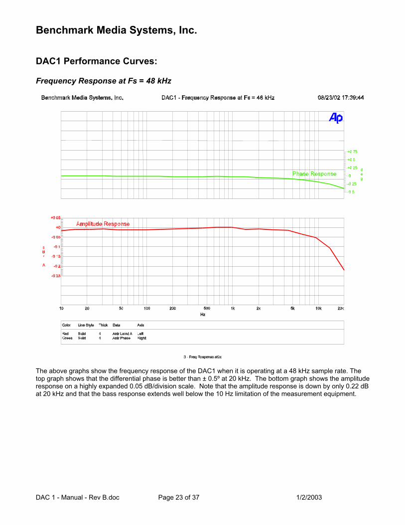
Frequency Response at Fs = 48 kHz
The above graphs show the frequency response of the DAC1 when it is operating at a 48 kHz sample rate. The top graph shows that the differential phase is better than ± 0.5º at 20 kHz. The bottom graph shows the amplitude response on a highly expanded 0.05 dB/division scale. Note that the amplitude response is down by only 0.22 dB at 20 kHz and that the bass response extends well below the 10 Hz limitation of the measurement equipment.
Benchmark Media Systems, Inc.
DAC 1 - Manual - Rev B.doc Page 24 of 37 1/2/2003
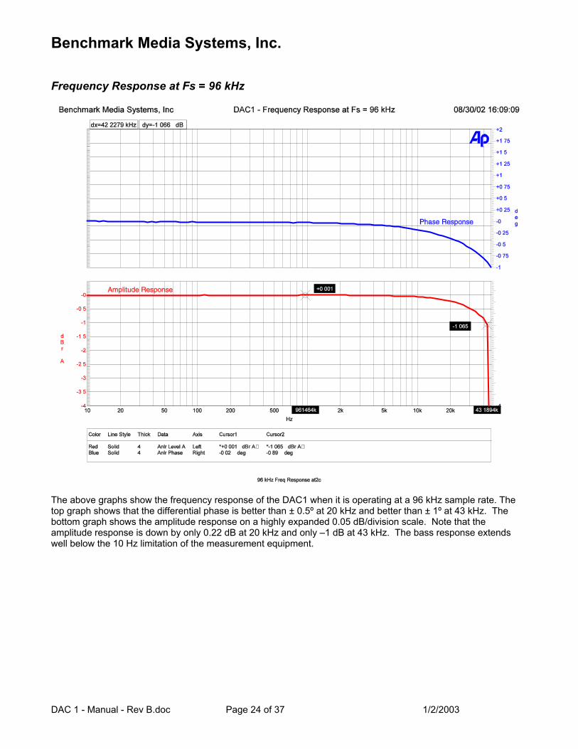
Frequency Response at Fs = 96 kHz
The above graphs show the frequency response of the DAC1 when it is operating at a 96 kHz sample rate. The top graph shows that the differential phase is better than ± 0.5º at 20 kHz and better than ± 1º at 43 kHz. The bottom graph shows the amplitude response on a highly expanded 0.05 dB/division scale. Note that the amplitude response is down by only 0.22 dB at 20 kHz and only –1 dB at 43 kHz. The bass response extends well below the 10 Hz limitation of the measurement equipment.
Benchmark Media Systems, Inc.
DAC 1 - Manual - Rev B.doc Page 25 of 37 1/2/2003
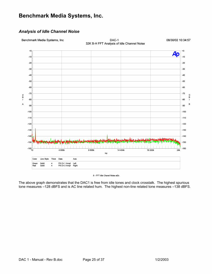
Analysis of Idle Channel Noise
The above graph demonstrates that the DAC1 is free from idle tones and clock crosstalk. The highest spurious tone measures –128 dBFS and is AC line related hum. The highest non-line related tone measures –138 dBFS.
Benchmark Media Systems, Inc.
DAC 1 - Manual - Rev B.doc Page 26 of 37 1/2/2003
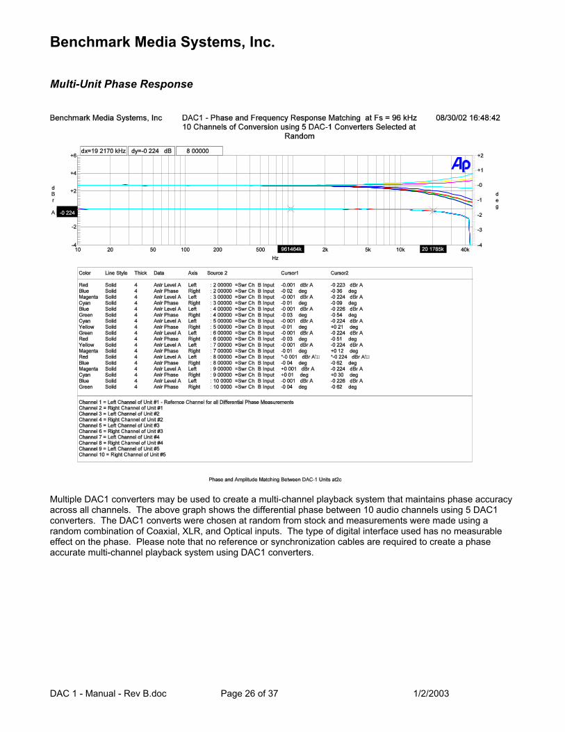
Multi-Unit Phase Response
Multiple DAC1 converters may be used to create a multi-channel playback system that maintains phase accuracy across all channels. The above graph shows the differential phase between 10 audio channels using 5 DAC1 converters. The DAC1 converts were chosen at random from stock and measurements were made using a random combination of Coaxial, XLR, and Optical inputs. The type of digital interface used has no measurable effect on the phase. Please note that no reference or synchronization cables are required to create a phase accurate multi-channel playback system using DAC1 converters.
Benchmark Media Systems, Inc.
DAC 1 - Manual - Rev B.doc Page 27 of 37 1/2/2003
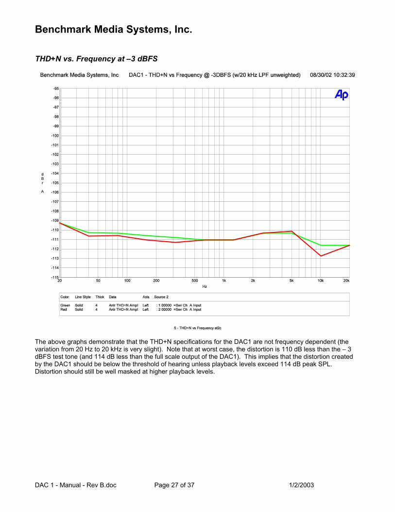
THD+N vs. Frequency at –3 dBFS
The above graphs demonstrate that the THD+N specifications for the DAC1 are not frequency dependent (the variation from 20 Hz to 20 kHz is very slight). Note that at worst case, the distortion is 110 dB less than the – 3 dBFS test tone (and 114 dB less than the full scale output of the DAC1). This implies that the distortion created by the DAC1 should be below the threshold of hearing unless playback levels exceed 114 dB peak SPL. Distortion should still be well masked at higher playback levels.
Benchmark Media Systems, Inc.
DAC 1 - Manual - Rev B.doc Page 28 of 37 1/2/2003
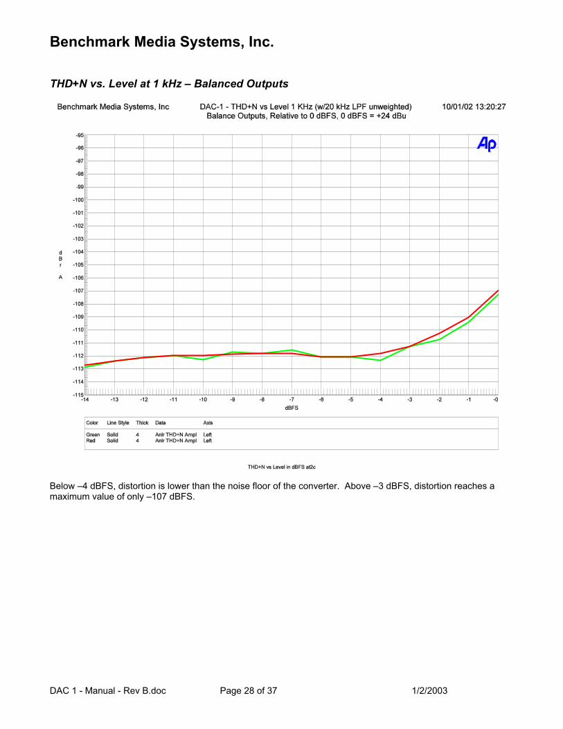
THD+N vs. Level at 1 kHz – Balanced Outputs
Below –4 dBFS, distortion is lower than the noise floor of the converter. Above –3 dBFS, distortion reaches a maximum value of only –107 dBFS.
Benchmark Media Systems, Inc.
DAC 1 - Manual - Rev B.doc Page 29 of 37 1/2/2003
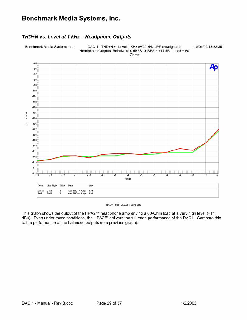
THD+N vs. Level at 1 kHz – Headphone Outputs
This graph shows the output of the HPA2™ headphone amp driving a 60-Ohm load at a very high level (+14 dBu). Even under these conditions, the HPA2™ delivers the full rated performance of the DAC1. Compare this to the performance of the balanced outputs (see previous graph).
Benchmark Media Systems, Inc.
DAC 1 - Manual - Rev B.doc Page 30 of 37 1/2/2003
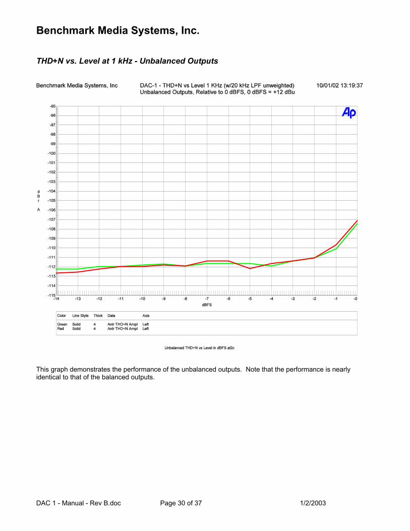
THD+N vs. Level at 1 kHz - Unbalanced Outputs
This graph demonstrates the performance of the unbalanced outputs. Note that the performance is nearly identical to that of the balanced outputs.
Benchmark Media Systems, Inc.
DAC 1 - Manual - Rev B.doc Page 31 of 37 1/2/2003
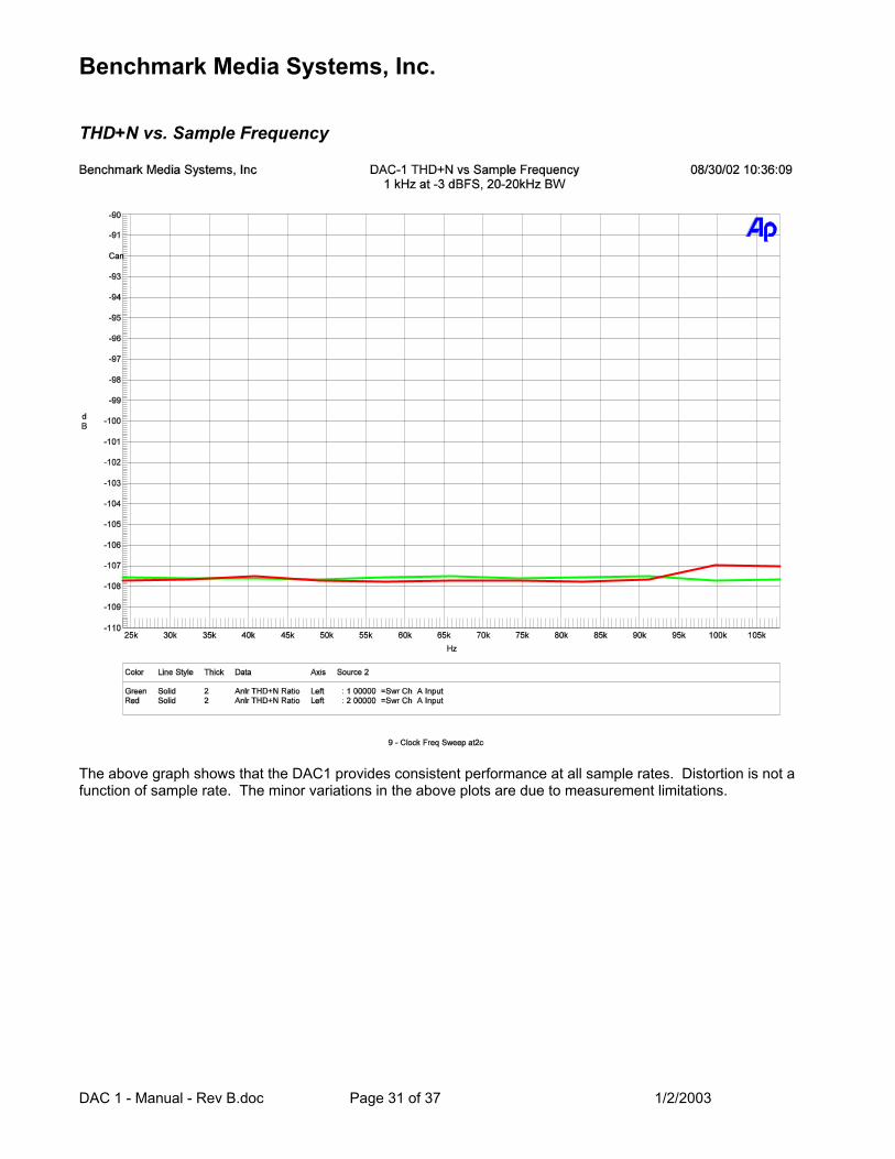
THD+N vs. Sample Frequency
The above graph shows that the DAC1 provides consistent performance at all sample rates. Distortion is not a function of sample rate. The minor variations in the above plots are due to measurement limitations.
Benchmark Media Systems, Inc.
DAC 1 - Manual - Rev B.doc Page 32 of 37 1/2/2003
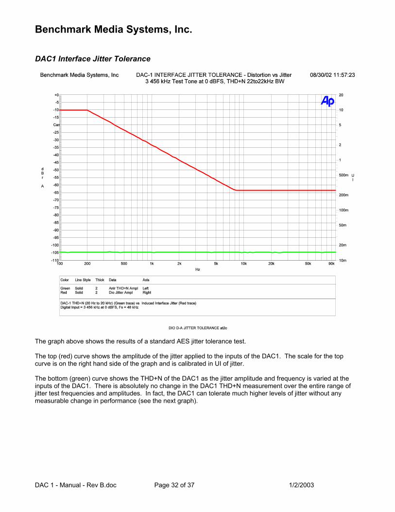
DAC1 Interface Jitter Tolerance
The graph above shows the results of a standard AES jitter tolerance test. The top (red) curve shows the amplitude of the jitter applied to the inputs of the DAC1. The scale for the top curve is on the right hand side of the graph and is calibrated in UI of jitter. The bottom (green) curve shows the THD+N of the DAC1 as the jitter amplitude and frequency is varied at the inputs of the DAC1. There is absolutely no change in the DAC1 THD+N measurement over the entire range of jitter test frequencies and amplitudes. In fact, the DAC1 can tolerate much higher levels of jitter without any measurable change in performance (see the next graph).
Benchmark Media Systems, Inc.
DAC 1 - Manual - Rev B.doc Page 33 of 37 1/2/2003
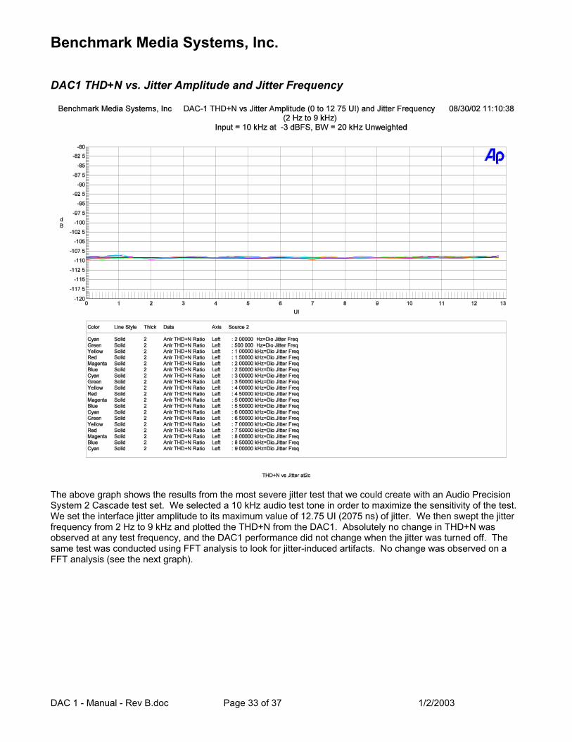
DAC1 THD+N vs. Jitter Amplitude and Jitter Frequency
The above graph shows the results from the most severe jitter test that we could create with an Audio Precision System 2 Cascade test set. We selected a 10 kHz audio test tone in order to maximize the sensitivity of the test. We set the interface jitter amplitude to its maximum value of 12.75 UI (2075 ns) of jitter. We then swept the jitter frequency from 2 Hz to 9 kHz and plotted the THD+N from the DAC1. Absolutely no change in THD+N was observed at any test frequency, and the DAC1 performance did not change when the jitter was turned off. The same test was conducted using FFT analysis to look for jitter-induced artifacts. No change was observed on a FFT analysis (see the next graph).
Benchmark Media Systems, Inc.
DAC 1 - Manual - Rev B.doc Page 34 of 37 1/2/2003
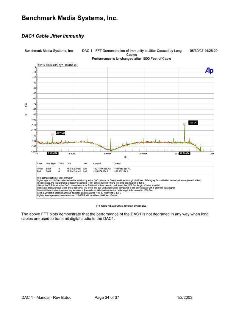
DAC1 Cable Jitter Immunity
The above FFT plots demonstrate that the performance of the DAC1 is not degraded in any way when long cables are used to transmit digital audio to the DAC1.
Benchmark Media Systems, Inc.
DAC 1 - Manual - Rev B.doc Page 35 of 37 1/2/2003
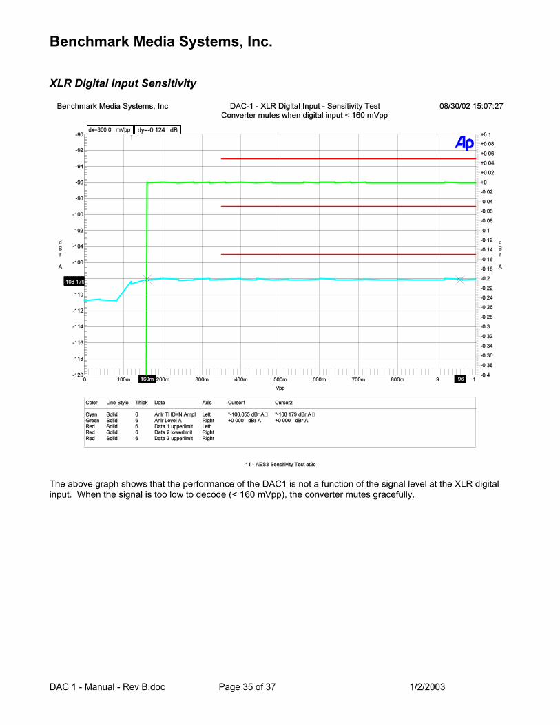
XLR Digital Input Sensitivity
The above graph shows that the performance of the DAC1 is not a function of the signal level at the XLR digital input. When the signal is too low to decode (< 160 mVpp), the converter mutes gracefully.

Benchmark Media Systems, Inc.
DAC 1 - Manual - Rev B.doc Page 36 of 37 1/2/2003
Coaxial Digital Input Sensitivity
The above graph shows that the performance of the DAC1 is not a function of the signal level at the coaxial digital input. When the signal is too low to decode (< 120 mVpp), the converter mutes gracefully.
Benchmark Media Systems, Inc.
DAC 1 - Manual - Rev B.doc Page 37 of 37 1/2/2003
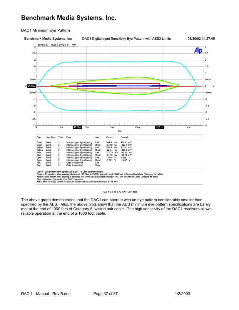
DAC1 Minimum Eye Pattern
The above graph demonstrates that the DAC1 can operate with an eye pattern considerably smaller than specified by the AES. Also, the above plots show that the AES minimum eye pattern specifications are barely met at the end of 1000 feet of Category 5 twisted pair cable. The high sensitivity of the DAC1 receivers allows reliable operation at the end of a 1000 foot cable.