Embed Size (px)
Citation preview

DA 40 NG AFM Introduction
Page 0 - 0a Rev. 0 01-Apr-2010 Doc. # 6.01.15-E
Intentionally left blank.
DA 40 NG AFM Introduction
Doc. # 6.01.15-E Rev. 0 01-Apr-2010 Page 0 - 1
FOREWORD
We congratulate you on the acquisition of your new DIAMOND DA 40 NG.
Skillful operation of an airplane increases both safety and the enjoyment of flying. Pleasetake the time therefore, to familiarize yourself with your new DIAMOND DA 40 NG.
This airplane may only be operated in accordance with the procedures and operatinglimitations of this Airplane Flight Manual.
Before this airplane is operated for the first time, the pilot must familiarize himself withthe complete contents of this Airplane Flight Manual.
In the event that you have obtained your DIAMOND DA 40 NG second-hand, please letus know your address, so that we can supply you with the publications necessary for thesafe operation of your airplane.
This document is protected by copyright. All associated rights, in particular those oftranslation, reprinting, radio transmission, reproduction by photo-mechanical or similarmeans and storing in data processing facilities, in whole or part, are reserved.
Copyright © by: DIAMOND AIRCRAFT INDUSTRIES GMBHN.A. Otto-Strasse 5A-2700 Wiener Neustadt, AustriaPhone. : +43-2622-26700Fax : +43-2622-26780E-Mail : [email protected]
Introduction DA 40 NG AFM
Page 0 - 2 Rev. 0 01-Apr-2010 Doc. # 6.01.15-E
0.1 APPROVAL
The content of approved chapters is approved by EASA. All other content is approvedby DAI under the authority of EASA DOA No. EASA.21J.052 in accordance with Part 21.
0.2 RECORD OF REVISIONS
All revisions of this manual, with the exception of • Temporary Revisions, • updates of the modification level (Section 1.1), • updated mass and balance information (Section 6.3), • updates of the Equipment Inventory (Section 6.5), and • updates of the List of Supplements (Section 9.2) must be recorded in the following table.
The new or amended text is indicated by a vertical black line at the left hand side of therevised page, with the revision number and date appearing at the bottom of the page.
If pages are revised which contain information valid for your particular serial number(modification level of the airplane, weighing data, Equipment Inventory, List ofSupplements), then this information must be transferred to the new pages in hand-writing.
Temporary Revisions are used to provide information on systems or equipment until thenext 'permanent' Revision of the Airplane Flight Manual. When a 'permanent' Revisioncovers a Mandatory or Optional Design Change Advisory (MÄM or OÄM), then thecorresponding Temporary Revision is superseded. For example: if Revision 5 coversOÄM 40-039, then the Temporary Revision TR OÄM-40-039 is superseded by the'permanent' Revision 5.
Cover pages of Temporary Revisions, if applicable, are inserted behind the cover pageof this manual, all other pages are inserted in front of the affected pages of this manual.
DA 40 NG AFM Introduction
Doc. # 6.01.15-E Rev. 0 01-Apr-2010 Page 0 - 3
Rev.No. Reason
Chap-ter Page(s) Date of
RevisionApproval
NoteDate
of ApprovalDate
Inserted Signature

Introduction DA 40 NG AFM
Page 0 - 4 Rev. 0 01-Apr-2010 Doc. # 6.01.15-E
Intentionally left blank.

DA 40 NG AFM Introduction
Doc. # 6.01.15-E Rev. 0 01-Apr-2010 Page 0 - 5
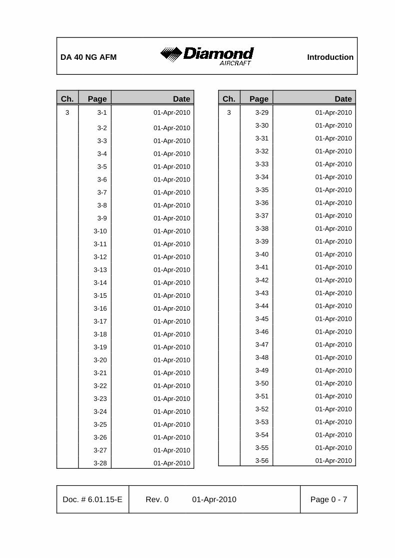
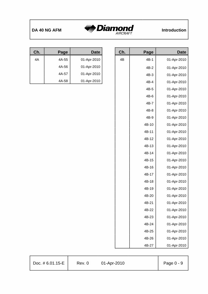
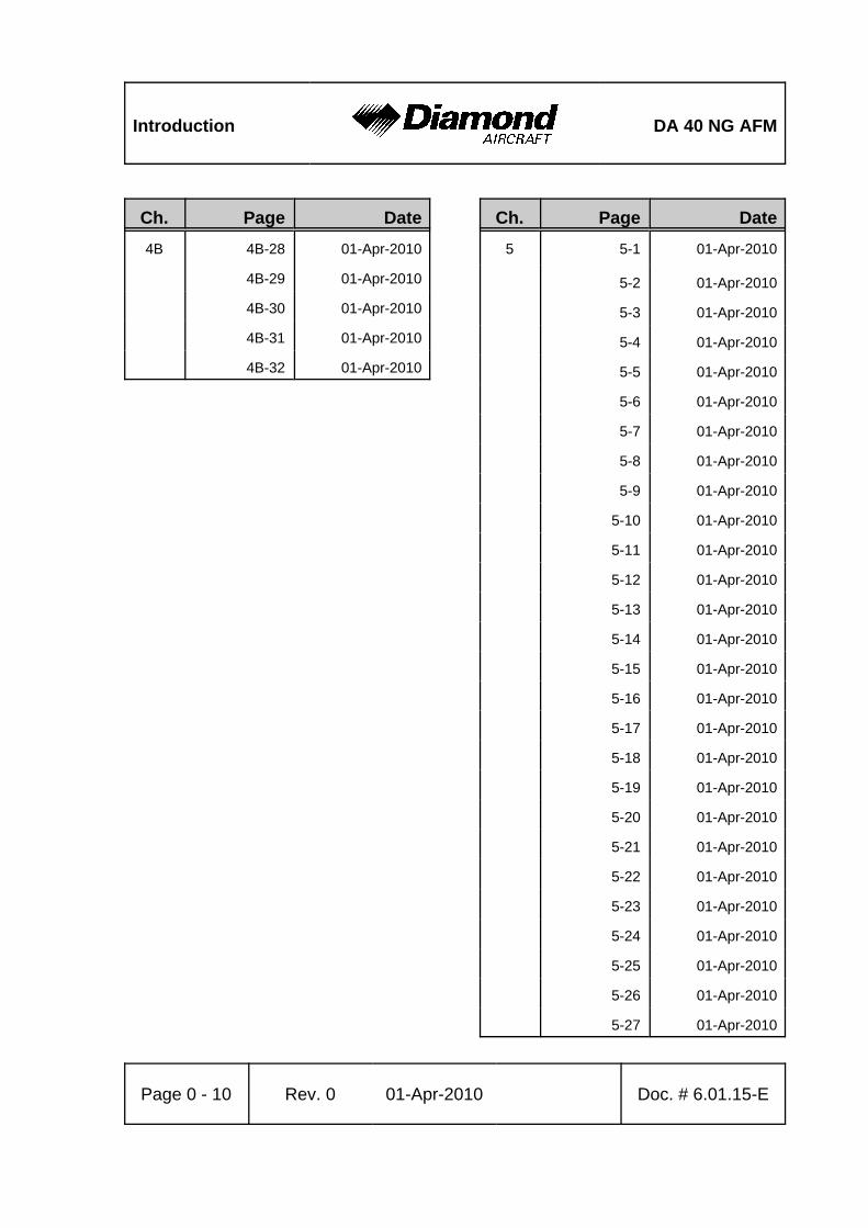
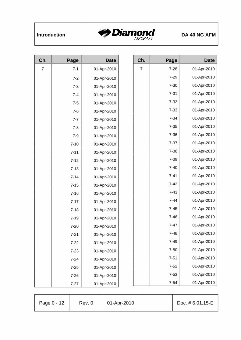
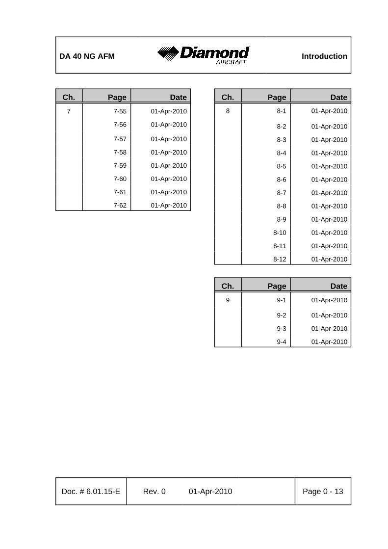
0.3 LIST OF EFFECTIVE PAGES
Ch. Page Date0 0-0 01-Apr-2010
0-0a 01-Apr-2010
0-1 01-Apr-2010
0-2 01-Apr-2010
0-3 01-Apr-2010
0-4 01-Apr-2010
0-5 01-Apr-2010
0-6 01-Apr-2010
0-7 01-Apr-2010
0-8 01-Apr-2010
0-9 01-Apr-2010
0-10 01-Apr-2010
0-11 01-Apr-2010
0-12 01-Apr-2010
0-13 01-Apr-2010
0-14 01-Apr-2010
0-15 01-Apr-2010
0-16 01-Apr-2010
Ch. Page Date1 1-1 01-Apr-2010
1-2 01-Apr-2010
1-3 01-Apr-2010
1-4 01-Apr-2010
1-5 01-Apr-2010
1-6 01-Apr-2010
1-7 01-Apr-2010
1-8 01-Apr-2010
1-9 01-Apr-2010
1-10 01-Apr-2010
1-11 01-Apr-2010
1-12 01-Apr-2010
1-13 01-Apr-2010
1-14 01-Apr-2010
1-15 01-Apr-2010
1-16 01-Apr-2010
1-17 01-Apr-2010
1-18 01-Apr-2010
1-19 01-Apr-2010
1-20 01-Apr-2010
1-21 01-Apr-2010
1-22 01-Apr-2010

Introduction DA 40 NG AFM
Page 0 - 6 Rev. 0 01-Apr-2010 Doc. # 6.01.15-E
Ch. Page Date2 appr. 2-1 01-Apr-2010
appr. 2-2 01-Apr-2010
appr. 2-3 01-Apr-2010
appr. 2-4 01-Apr-2010
appr. 2-5 01-Apr-2010
appr. 2-6 01-Apr-2010
appr. 2-7 01-Apr-2010
appr. 2-8 01-Apr-2010
appr. 2-9 01-Apr-2010
appr. 2-10 01-Apr-2010
appr. 2-11 01-Apr-2010
appr. 2-12 01-Apr-2010
appr. 2-13 01-Apr-2010
appr. 2-14 01-Apr-2010
appr. 2-15 01-Apr-2010
appr. 2-16 01-Apr-2010
appr. 2-17 01-Apr-2010
appr. 2-18 01-Apr-2010
appr. 2-19 01-Apr-2010
appr. 2-20 01-Apr-2010
appr. 2-21 01-Apr-2010
appr. 2-22 01-Apr-2010
appr. 2-23 01-Apr-2010
appr. 2-24 01-Apr-2010
appr. 2-25 01-Apr-2010
appr. 2-26 01-Apr-2010
appr. 2-27 01-Apr-2010
Ch. Page Date2 appr. 2-28 01-Apr-2010
appr. 2-29 01-Apr-2010
appr. 2-30 01-Apr-2010
appr. 2-31 01-Apr-2010
appr. 2-32 01-Apr-2010
appr. 2-33 01-Apr-2010
appr. 2-34 01-Apr-2010
appr. 2-35 01-Apr-2010
appr. 2-36 01-Apr-2010
appr. 2-37 01-Apr-2010
appr. 2-38 01-Apr-2010
appr. 2-39 01-Apr-2010
appr. 2-40 01-Apr-2010
DA 40 NG AFM Introduction
Doc. # 6.01.15-E Rev. 0 01-Apr-2010 Page 0 - 7
Ch. Page Date3 3-1 01-Apr-2010
3-2 01-Apr-2010
3-3 01-Apr-2010
3-4 01-Apr-2010
3-5 01-Apr-2010
3-6 01-Apr-2010
3-7 01-Apr-2010
3-8 01-Apr-2010
3-9 01-Apr-2010
3-10 01-Apr-2010
3-11 01-Apr-2010
3-12 01-Apr-2010
3-13 01-Apr-2010
3-14 01-Apr-2010
3-15 01-Apr-2010
3-16 01-Apr-2010
3-17 01-Apr-2010
3-18 01-Apr-2010
3-19 01-Apr-2010
3-20 01-Apr-2010
3-21 01-Apr-2010
3-22 01-Apr-2010
3-23 01-Apr-2010
3-24 01-Apr-2010
3-25 01-Apr-2010
3-26 01-Apr-2010
3-27 01-Apr-2010
3-28 01-Apr-2010
Ch. Page Date3 3-29 01-Apr-2010
3-30 01-Apr-2010
3-31 01-Apr-2010
3-32 01-Apr-2010
3-33 01-Apr-2010
3-34 01-Apr-2010
3-35 01-Apr-2010
3-36 01-Apr-2010
3-37 01-Apr-2010
3-38 01-Apr-2010
3-39 01-Apr-2010
3-40 01-Apr-2010
3-41 01-Apr-2010
3-42 01-Apr-2010
3-43 01-Apr-2010
3-44 01-Apr-2010
3-45 01-Apr-2010
3-46 01-Apr-2010
3-47 01-Apr-2010
3-48 01-Apr-2010
3-49 01-Apr-2010
3-50 01-Apr-2010
3-51 01-Apr-2010
3-52 01-Apr-2010
3-53 01-Apr-2010
3-54 01-Apr-2010
3-55 01-Apr-2010
3-56 01-Apr-2010

Introduction DA 40 NG AFM
Page 0 - 8 Rev. 0 01-Apr-2010 Doc. # 6.01.15-E
Ch. Page Date4A 4A-1 01-Apr-2010
4A-2 01-Apr-2010
4A-3 01-Apr-2010
4A-4 01-Apr-2010
4A-5 01-Apr-2010
4A-6 01-Apr-2010
4A-7 01-Apr-2010
4A-8 01-Apr-2010
4A-9 01-Apr-2010
4A-10 01-Apr-2010
4A-11 01-Apr-2010
4A-12 01-Apr-2010
4A-13 01-Apr-2010
4A-14 01-Apr-2010
4A-15 01-Apr-2010
4A-16 01-Apr-2010
4A-17 01-Apr-2010
4A-18 01-Apr-2010
4A-19 01-Apr-2010
4A-20 01-Apr-2010
4A-21 01-Apr-2010
4A-22 01-Apr-2010
4A-23 01-Apr-2010
4A-24 01-Apr-2010
4A-25 01-Apr-2010
4A-26 01-Apr-2010
4A-27 01-Apr-2010
Ch. Page Date4A 4A-28 01-Apr-2010
4A-29 01-Apr-2010
4A-30 01-Apr-2010
4A-31 01-Apr-2010
4A-32 01-Apr-2010
4A-33 01-Apr-2010
4A-34 01-Apr-2010
4A-35 01-Apr-2010
4A-36 01-Apr-2010
4A-37 01-Apr-2010
4A-38 01-Apr-2010
4A-39 01-Apr-2010
4A-40 01-Apr-2010
4A-41 01-Apr-2010
4A-42 01-Apr-2010
4A-43 01-Apr-2010
4A-44 01-Apr-2010
4A-45 01-Apr-2010
4A-46 01-Apr-2010
4A-47 01-Apr-2010
4A-48 01-Apr-2010
4A-49 01-Apr-2010
4A-50 01-Apr-2010
4A-51 01-Apr-2010
4A-52 01-Apr-2010
4A-53 01-Apr-2010
4A-54 01-Apr-2010
DA 40 NG AFM Introduction
Doc. # 6.01.15-E Rev. 0 01-Apr-2010 Page 0 - 9
Ch. Page Date4A 4A-55 01-Apr-2010
4A-56 01-Apr-2010
4A-57 01-Apr-2010
4A-58 01-Apr-2010
Ch. Page Date4B 4B-1 01-Apr-2010
4B-2 01-Apr-2010
4B-3 01-Apr-2010
4B-4 01-Apr-2010
4B-5 01-Apr-2010
4B-6 01-Apr-2010
4B-7 01-Apr-2010
4B-8 01-Apr-2010
4B-9 01-Apr-2010
4B-10 01-Apr-2010
4B-11 01-Apr-2010
4B-12 01-Apr-2010
4B-13 01-Apr-2010
4B-14 01-Apr-2010
4B-15 01-Apr-2010
4B-16 01-Apr-2010
4B-17 01-Apr-2010
4B-18 01-Apr-2010
4B-19 01-Apr-2010
4B-20 01-Apr-2010
4B-21 01-Apr-2010
4B-22 01-Apr-2010
4B-23 01-Apr-2010
4B-24 01-Apr-2010
4B-25 01-Apr-2010
4B-26 01-Apr-2010
4B-27 01-Apr-2010
Introduction DA 40 NG AFM
Page 0 - 10 Rev. 0 01-Apr-2010 Doc. # 6.01.15-E
Ch. Page Date4B 4B-28 01-Apr-2010
4B-29 01-Apr-2010
4B-30 01-Apr-2010
4B-31 01-Apr-2010
4B-32 01-Apr-2010
Ch. Page Date5 5-1 01-Apr-2010
5-2 01-Apr-2010
5-3 01-Apr-2010
5-4 01-Apr-2010
5-5 01-Apr-2010
5-6 01-Apr-2010
5-7 01-Apr-2010
5-8 01-Apr-2010
5-9 01-Apr-2010
5-10 01-Apr-2010
5-11 01-Apr-2010
5-12 01-Apr-2010
5-13 01-Apr-2010
5-14 01-Apr-2010
5-15 01-Apr-2010
5-16 01-Apr-2010
5-17 01-Apr-2010
5-18 01-Apr-2010
5-19 01-Apr-2010
5-20 01-Apr-2010
5-21 01-Apr-2010
5-22 01-Apr-2010
5-23 01-Apr-2010
5-24 01-Apr-2010
5-25 01-Apr-2010
5-26 01-Apr-2010
5-27 01-Apr-2010

DA 40 NG AFM Introduction
Doc. # 6.01.15-E Rev. 0 01-Apr-2010 Page 0 - 11
Ch. Page Date5 5-28 01-Apr-2010
5-29 01-Apr-2010
5-30 01-Apr-2010
Ch. Page Date6 6-1 01-Apr-2010
6-2 01-Apr-2010
6-3 01-Apr-2010
6-4 01-Apr-2010
6-5 01-Apr-2010
6-6 01-Apr-2010
6-7 01-Apr-2010
6-8 01-Apr-2010
6-9 01-Apr-2010
6-10 01-Apr-2010
6-11 01-Apr-2010
6-12 01-Apr-2010
6-13 01-Apr-2010
6-14 01-Apr-2010
6-15 01-Apr-2010
6-16 01-Apr-2010
6-17 01-Apr-2010
6-18 01-Apr-2010
6-19 01-Apr-2010
6-20 01-Apr-2010
6-21 01-Apr-2010
6-22 01-Apr-2010
6-23 01-Apr-2010
6-24 01-Apr-2010
Introduction DA 40 NG AFM
Page 0 - 12 Rev. 0 01-Apr-2010 Doc. # 6.01.15-E
Ch. Page Date7 7-1 01-Apr-2010
7-2 01-Apr-2010
7-3 01-Apr-2010
7-4 01-Apr-2010
7-5 01-Apr-2010
7-6 01-Apr-2010
7-7 01-Apr-2010
7-8 01-Apr-2010
7-9 01-Apr-2010
7-10 01-Apr-2010
7-11 01-Apr-2010
7-12 01-Apr-2010
7-13 01-Apr-2010
7-14 01-Apr-2010
7-15 01-Apr-2010
7-16 01-Apr-2010
7-17 01-Apr-2010
7-18 01-Apr-2010
7-19 01-Apr-2010
7-20 01-Apr-2010
7-21 01-Apr-2010
7-22 01-Apr-2010
7-23 01-Apr-2010
7-24 01-Apr-2010
7-25 01-Apr-2010
7-26 01-Apr-2010
7-27 01-Apr-2010
Ch. Page Date7 7-28 01-Apr-2010
7-29 01-Apr-2010
7-30 01-Apr-2010
7-31 01-Apr-2010
7-32 01-Apr-2010
7-33 01-Apr-2010
7-34 01-Apr-2010
7-35 01-Apr-2010
7-36 01-Apr-2010
7-37 01-Apr-2010
7-38 01-Apr-2010
7-39 01-Apr-2010
7-40 01-Apr-2010
7-41 01-Apr-2010
7-42 01-Apr-2010
7-43 01-Apr-2010
7-44 01-Apr-2010
7-45 01-Apr-2010
7-46 01-Apr-2010
7-47 01-Apr-2010
7-48 01-Apr-2010
7-49 01-Apr-2010
7-50 01-Apr-2010
7-51 01-Apr-2010
7-52 01-Apr-2010
7-53 01-Apr-2010
7-54 01-Apr-2010
DA 40 NG AFM Introduction
Doc. # 6.01.15-E Rev. 0 01-Apr-2010 Page 0 - 13
Ch. Page Date7 7-55 01-Apr-2010
7-56 01-Apr-2010
7-57 01-Apr-2010
7-58 01-Apr-2010
7-59 01-Apr-2010
7-60 01-Apr-2010
7-61 01-Apr-2010
7-62 01-Apr-2010
Ch. Page Date8 8-1 01-Apr-2010
8-2 01-Apr-2010
8-3 01-Apr-2010
8-4 01-Apr-2010
8-5 01-Apr-2010
8-6 01-Apr-2010
8-7 01-Apr-2010
8-8 01-Apr-2010
8-9 01-Apr-2010
8-10 01-Apr-2010
8-11 01-Apr-2010
8-12 01-Apr-2010
Ch. Page Date9 9-1 01-Apr-2010
9-2 01-Apr-2010
9-3 01-Apr-2010
9-4 01-Apr-2010

Introduction DA 40 NG AFM
Page 0 - 14 Rev. 0 01-Apr-2010 Doc. # 6.01.15-E
Intentionally left blank.
DA 40 NG AFM Introduction
Doc. # 6.01.15-E Rev. 0 01-Apr-2010 Page 0 - 15
0.4 TABLE OF CONTENTS
ChapterGENERAL
(a non-approved chapter) . . . . . . . . . . . . . . . . . . . . . . . . . . . . . . . . . . . . . . . 1
OPERATING LIMITATIONS(an approved chapter) . . . . . . . . . . . . . . . . . . . . . . . . . . . . . . . . . . . . . . . . . . 2
EMERGENCY PROCEDURES(a non-approved chapter) . . . . . . . . . . . . . . . . . . . . . . . . . . . . . . . . . . . . . . . 3
NORMAL OPERATING PROCEDURES(a non-approved chapter) . . . . . . . . . . . . . . . . . . . . . . . . . . . . . . . . . . . . . . 4A
ABNORMAL OPERATING PROCEDURES(a non-approved chapter) . . . . . . . . . . . . . . . . . . . . . . . . . . . . . . . . . . . . . . 4B
PERFORMANCE(a non-approved chapter) . . . . . . . . . . . . . . . . . . . . . . . . . . . . . . . . . . . . . . . 5
MASS AND BALANCE / EQUIPMENT LIST(a non-approved chapter) . . . . . . . . . . . . . . . . . . . . . . . . . . . . . . . . . . . . . . . 6
DESCRIPTION OF THE AIRPLANE AND ITS SYSTEMS(a non-approved chapter) . . . . . . . . . . . . . . . . . . . . . . . . . . . . . . . . . . . . . . . 7
AIRPLANE HANDLING, CARE AND MAINTENANCE(a non-approved chapter) . . . . . . . . . . . . . . . . . . . . . . . . . . . . . . . . . . . . . . . 8
SUPPLEMENTS . . . . . . . . . . . . . . . . . . . . . . . . . . . . . . . . . . . . . . . . . . . . . . . . . . . . 9

Introduction DA 40 NG AFM
Page 0 - 16 Rev. 0 01-Apr-2010 Doc. # 6.01.15-E
Intentionally left blank.
DA 40 NG AFM General
Doc. # 6.01.15-E Rev. 0 01-Apr-2010 Page 1 - 1
CHAPTER 1GENERAL
Page
1.1 INTRODUCTION . . . . . . . . . . . . . . . . . . . . . . . . . . . . . . . . . . . . . . . 1-21.2 CERTIFICATION BASIS . . . . . . . . . . . . . . . . . . . . . . . . . . . . . . . . . 1-31.3 WARNINGS, CAUTIONS AND NOTES . . . . . . . . . . . . . . . . . . . . . 1-41.4 DIMENSIONS . . . . . . . . . . . . . . . . . . . . . . . . . . . . . . . . . . . . . . . . . 1-51.5 DEFINITIONS AND ABBREVIATIONS . . . . . . . . . . . . . . . . . . . . . . 1-71.6 UNITS OF MEASUREMENT . . . . . . . . . . . . . . . . . . . . . . . . . . . . . 1-15
1.6.1 CONVERSION FACTORS . . . . . . . . . . . . . . . . . . . . . . . . . 1-151.6.2 CONVERSION CHART LITER / US GALLON . . . . . . . . . . 1-17
1.7 THREE-VIEW DRAWING . . . . . . . . . . . . . . . . . . . . . . . . . . . . . . . 1-181.8 G1000 AVIONICS SYSTEM . . . . . . . . . . . . . . . . . . . . . . . . . . . . . 1-191.9 SOURCE DOCUMENTATION . . . . . . . . . . . . . . . . . . . . . . . . . . . 1-21
1.9.1 ENGINE AND ENGINE INSTRUMENTS . . . . . . . . . . . . . . . 1-211.9.2 PROPELLER . . . . . . . . . . . . . . . . . . . . . . . . . . . . . . . . . . . . 1-221.9.3 AVIONICS SYSTEM . . . . . . . . . . . . . . . . . . . . . . . . . . . . . . 1-22
General DA 40 NG AFM
Page 1 - 2 Rev. 0 01-Apr-2010 Doc. # 6.01.15-E
1.1 INTRODUCTION
This Airplane Flight Manual has been prepared in order to provide pilots and instructorswith all the information required for the safe and efficient operation of the airplane.
The Airplane Flight Manual includes all the data which must be made available to the pilotaccording to the JAR-23 requirement. Beyond this, it contains further data and operatinginstructions which, in the manufacturer’s opinion, could be of value to the pilot.
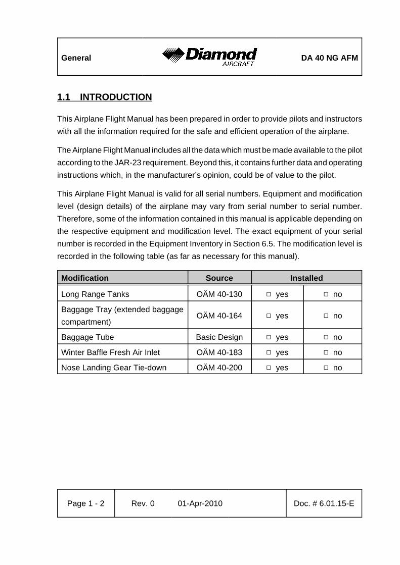
This Airplane Flight Manual is valid for all serial numbers. Equipment and modificationlevel (design details) of the airplane may vary from serial number to serial number.Therefore, some of the information contained in this manual is applicable depending onthe respective equipment and modification level. The exact equipment of your serialnumber is recorded in the Equipment Inventory in Section 6.5. The modification level isrecorded in the following table (as far as necessary for this manual).
Modification Source Installed
Long Range Tanks OÄM 40-130 9 yes 9 no
Baggage Tray (extended baggagecompartment)
OÄM 40-164 9 yes 9 no
Baggage Tube Basic Design 9 yes 9 no
Winter Baffle Fresh Air Inlet OÄM 40-183 9 yes 9 no
Nose Landing Gear Tie-down OÄM 40-200 9 yes 9 no
DA 40 NG AFM General
Doc. # 6.01.15-E Rev. 0 01-Apr-2010 Page 1 - 3
This Airplane Flight Manual must be kept on board the airplane at all times. Its designatedplace is the side bag of the forward left seat.
CAUTIONThe DA 40 NG is a single engine airplane. When theoperating limitations and maintenance requirements arecomplied with, it has the high degree of reliability which isrequired by the certification basis. Nevertheless, an enginefailure is not completely impossible. For this reason, flightsduring the night, on top, under instrument meteorologicalconditions (IMC), or above terrain which is unsuitable for alanding, constitute a risk. It is therefore highly recommendedto select flight times and flight routes such that this risk isminimized.
1.2 CERTIFICATION BASIS
This airplane has been type certified in accordance with the procedures established byEASA. The certification basis is JAR-23, published on 11-Mar-1994 and additionalrequirements as laid down in CRI A-01.

General DA 40 NG AFM
Page 1 - 4 Rev. 0 01-Apr-2010 Doc. # 6.01.15-E
1.3 WARNINGS, CAUTIONS AND NOTES
Special statements in the Airplane Flight Manual concerning the safety or operation ofthe airplane are highlighted by being prefixed by one of the following terms:
WARNINGmeans that the non-observation of the correspondingprocedure leads to an immediate or important degradationin flight safety.
CAUTIONmeans that the non-observation of the correspondingprocedure leads to a minor or to a more or less long termdegradation in flight safety.
NOTEdraws the attention to any special item not directly related tosafety but which is important or unusual.
DA 40 NG AFM General
Doc. # 6.01.15-E Rev. 0 01-Apr-2010 Page 1 - 5
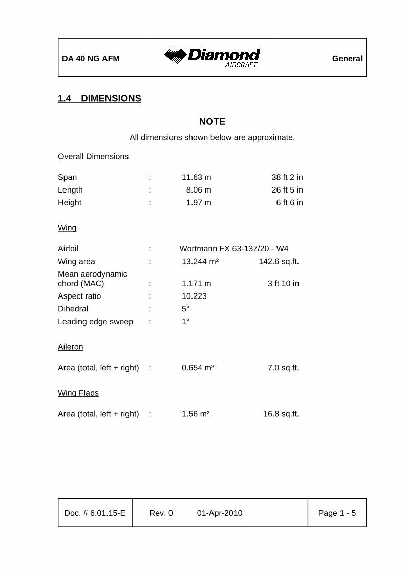
1.4 DIMENSIONS
NOTEAll dimensions shown below are approximate.
Overall Dimensions
Span : 11.63 m 38 ft 2 inLength : 8.06 m 26 ft 5 inHeight : 1.97 m 6 ft 6 in
Wing
Airfoil : Wortmann FX 63-137/20 - W4Wing area : 13.244 m² 142.6 sq.ft.Mean aerodynamicchord (MAC) : 1.171 m 3 ft 10 inAspect ratio : 10.223Dihedral : 5°Leading edge sweep : 1°
Aileron
Area (total, left + right) : 0.654 m² 7.0 sq.ft.
Wing Flaps
Area (total, left + right) : 1.56 m² 16.8 sq.ft.
General DA 40 NG AFM
Page 1 - 6 Rev. 0 01-Apr-2010 Doc. # 6.01.15-E
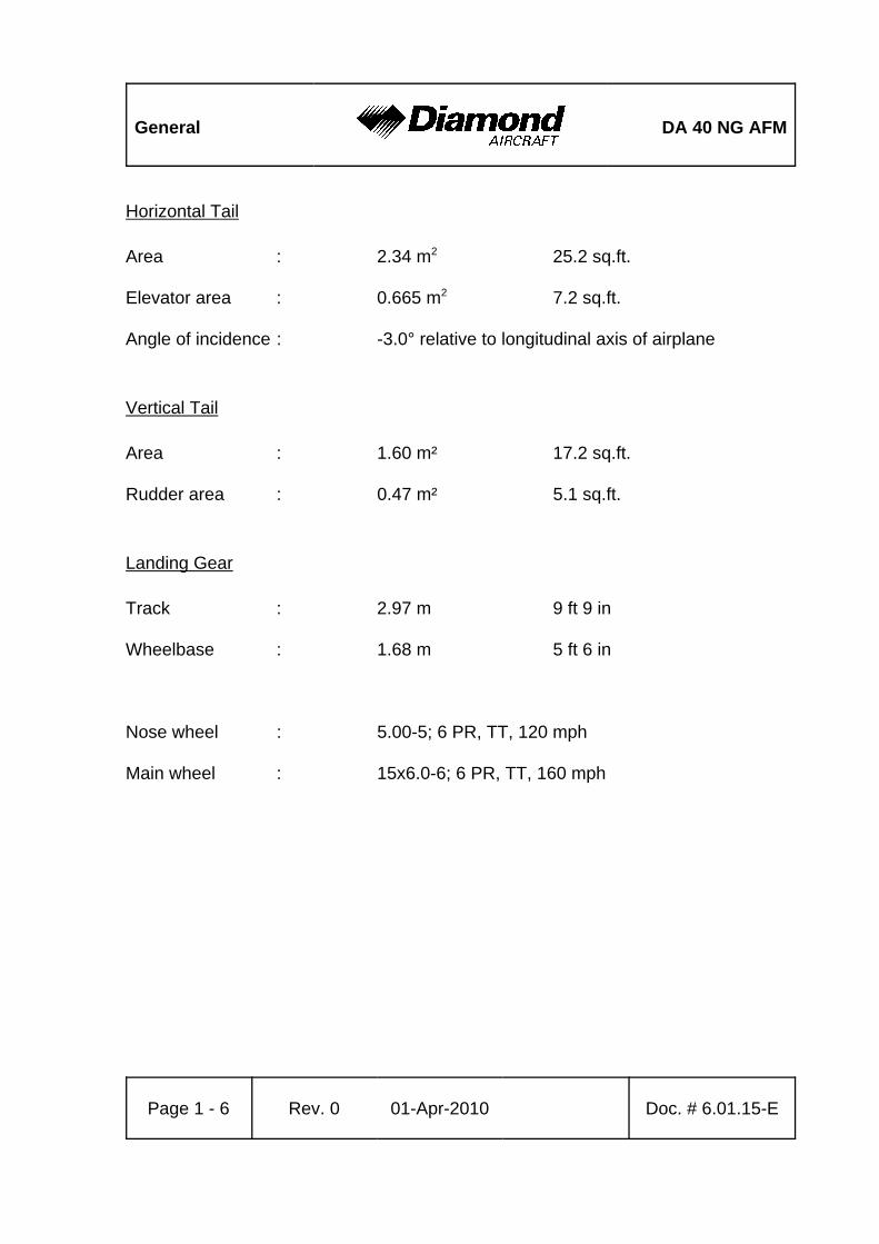
Horizontal Tail
Area : 2.34 m2 25.2 sq.ft.
Elevator area : 0.665 m2 7.2 sq.ft.
Angle of incidence : -3.0° relative to longitudinal axis of airplane
Vertical Tail
Area : 1.60 m² 17.2 sq.ft.
Rudder area : 0.47 m² 5.1 sq.ft.
Landing Gear
Track : 2.97 m 9 ft 9 in
Wheelbase : 1.68 m 5 ft 6 in
Nose wheel : 5.00-5; 6 PR, TT, 120 mph
Main wheel : 15x6.0-6; 6 PR, TT, 160 mph
DA 40 NG AFM General
Doc. # 6.01.15-E Rev. 0 01-Apr-2010 Page 1 - 7
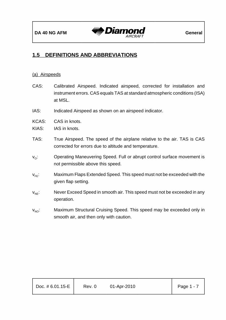
1.5 DEFINITIONS AND ABBREVIATIONS
(a) Airspeeds
CAS: Calibrated Airspeed. Indicated airspeed, corrected for installation andinstrument errors. CAS equals TAS at standard atmospheric conditions (ISA)at MSL.
IAS: Indicated Airspeed as shown on an airspeed indicator.
KCAS: CAS in knots.KIAS: IAS in knots.
TAS: True Airspeed. The speed of the airplane relative to the air. TAS is CAScorrected for errors due to altitude and temperature.
vO: Operating Maneuvering Speed. Full or abrupt control surface movement isnot permissible above this speed.
vFE: Maximum Flaps Extended Speed. This speed must not be exceeded with thegiven flap setting.
vNE: Never Exceed Speed in smooth air. This speed must not be exceeded in anyoperation.
vNO: Maximum Structural Cruising Speed. This speed may be exceeded only insmooth air, and then only with caution.
General DA 40 NG AFM
Page 1 - 8 Rev. 0 01-Apr-2010 Doc. # 6.01.15-E
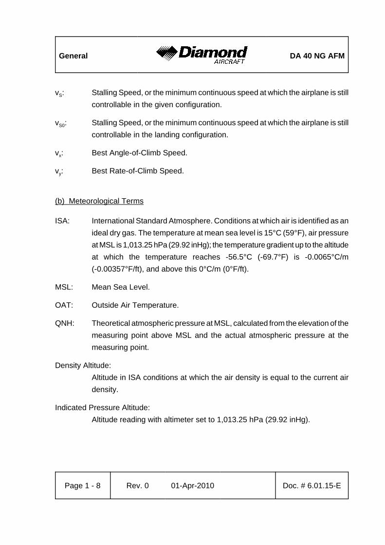
vS: Stalling Speed, or the minimum continuous speed at which the airplane is stillcontrollable in the given configuration.
vS0: Stalling Speed, or the minimum continuous speed at which the airplane is stillcontrollable in the landing configuration.
vx: Best Angle-of-Climb Speed.
vy: Best Rate-of-Climb Speed.
(b) Meteorological Terms
ISA: International Standard Atmosphere. Conditions at which air is identified as anideal dry gas. The temperature at mean sea level is 15°C (59°F), air pressureat MSL is 1,013.25 hPa (29.92 inHg); the temperature gradient up to the altitudeat which the temperature reaches -56.5°C (-69.7°F) is -0.0065°C/m(-0.00357°F/ft), and above this 0°C/m (0°F/ft).
MSL: Mean Sea Level.
OAT: Outside Air Temperature.
QNH: Theoretical atmospheric pressure at MSL, calculated from the elevation of themeasuring point above MSL and the actual atmospheric pressure at themeasuring point.
Density Altitude:Altitude in ISA conditions at which the air density is equal to the current airdensity.
Indicated Pressure Altitude:Altitude reading with altimeter set to 1,013.25 hPa (29.92 inHg).

DA 40 NG AFM General
Doc. # 6.01.15-E Rev. 0 01-Apr-2010 Page 1 - 9
Pressure Altitude:Altitude above MSL, indicated by a barometric altimeter which is set to1,013.25 hPa (29.92 inHg). The pressure altitude is the indicated pressurealtitude corrected for installation and instrument errors.
In this Airplane Flight Manual altimeter instrument errors are regarded as zero.
Wind: The wind speeds which are shown as variables in the diagrams in this manualshould be regarded as headwind or tailwind components of the measured wind.
(c) Flight Performance and Flight Planning
AGL: Above ground level.
Demonstrated Crosswind Component:The speed of the crosswind component at which adequate maneuverabilityfor take-off and landing has been demonstrated during type certification.
MET: Weather, weather advice.
NAV: Navigation, route planning.
General DA 40 NG AFM
Page 1 - 10 Rev. 0 01-Apr-2010 Doc. # 6.01.15-E
(d) Mass and Balance
CG: Center of Gravity, also called 'center of mass'. Imaginary point in which theairplane mass is assumed to be concentrated for mass and balancecalculations. Its distance from the Datum Plane is equal to the Center of GravityMoment Arm.
Center of Gravity Moment Arm:The Moment Arm which is obtained if one divides the sum of the individualmoments of the airplane by its total mass.
Center of Gravity Limits:The Center of Gravity range within which the airplane, at a given mass, mustbe operated.
DP: Datum Plane; an imaginary vertical plane from which all horizontal distancesfor center of gravity calculations are measured.
Empty Mass:The mass of the airplane including unusable fuel, all operating consumablesand the maximum quantity of oil.
Maximum Take-off Mass:The maximum permissible mass for take-off.
Maximum Landing Mass:The highest mass for landing conditions at the maximum descent velocity. Thiscondition was used in the strength calculations to determine the landing gearloads during a particularly hard landing.
Maximum Zero Fuel Mass:The highest permissible mass with empty fuel tanks.

DA 40 NG AFM General
Doc. # 6.01.15-E Rev. 0 01-Apr-2010 Page 1 - 11
Moment Arm:The horizontal distance from the Datum Plane to the Center of Gravity of acomponent.
Moment: The mass of a component multiplied by its moment arm.
Usable Fuel:The quantity of fuel available for flight planning.
Unusable Fuel:The quantity of fuel remaining in the tank which cannot be used for flight.
Useful Load:The difference between take-off mass and empty mass.
(e) Engine
CT: Coolant Temperature.
EECU: Electronic Engine Control Unit.
GT: Gearbox Temperature.
LOAD: Engine output power in percent of take-off power.
OP: Oil Pressure (oil pressure in the lubrication system of the engine).
OT: Oil Temperature (oil temperature in the lubrication system of the engine).
RPM: Revolutions per minute (rotational speed of the propeller).
General DA 40 NG AFM
Page 1 - 12 Rev. 0 01-Apr-2010 Doc. # 6.01.15-E
(f) Designation of the Circuit Breakers on the Instrument Panel
ESSENTIAL BUS
HORIZON Artificial Horizon (Attitude Gyro)ADC Air Data ComputerAHRS Attitude and Heading Reference SystemCOM1 COM Radio No. 1FLOOD Flood LightGPS/NAV1 Global Positioning System and NAV Receiver No. 1XPDR TransponderLANDING Landing LightPFD Primary Flight DisplayPITOT Pitot Heating SystemFLAPS Flap SystemMASTER CONTROL Master Control (Avionics Relay)ESS TIE Bus InterconnectionENG INST Engine Instruments
MAIN BUS
MAIN TIE Bus InterconnectionXFR PUMP Fuel Transfer PumpMFD Multi Function DisplayINST. LT Instrument LightsAV/CDU FAN Avionic-, CDU-Cooling FansPWR PowerSTROBE Strobe Lights (= Anti Collision Lights)POSITION Position LightsTAXI/MAP Taxi Light / Map LightsSTART StarterAV. BUS Avionic Bus
DA 40 NG AFM General
Doc. # 6.01.15-E Rev. 0 01-Apr-2010 Page 1 - 13
EECU BUS
EECU A ECU AEECU B ECU BFUEL PUMP A ECU A Fuel PumpFUEL PUMP B ECU B Fuel Pump
AVIONICS BUS
GPS/NAV2 Global Positioning System and NAV Receiver No. 2COM2 COM Radio No. 2AUDIO Audio Panel / Marker Beacon ReceiverAUTOPILOT Autopilot SystemADF Automatic Direction FinderDME Distance Measuring EquipmentWX500 StormscopeTAS Traffic Advisory System
(g) Equipment
ELT: Emergency Locator Transmitter.
(h) Design Change Advisories
MÄM: Mandatory Design Change Advisory.
OÄM: Optional Design Change Advisory.
General DA 40 NG AFM
Page 1 - 14 Rev. 0 01-Apr-2010 Doc. # 6.01.15-E
(i) Miscellaneous
ACG: Austro Control GmbH (formerly BAZ, Federal Office of Civil Aviation).
ATC: Air Traffic Control.
CFRP: Carbon Fiber Reinforced Plastic.
EASA: European Aviation Safety Agency.
GFRP: Glass Fiber Reinforced Plastic.
GIA: Garmin Integrated Avionics.
JAR: Joint Aviation Requirements.
DA 40 NG AFM General
Doc. # 6.01.15-E Rev. 0 01-Apr-2010 Page 1 - 15
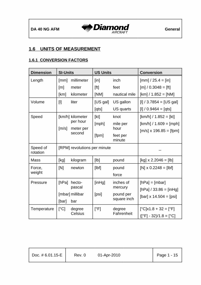
1.6 UNITS OF MEASUREMENT
1.6.1 CONVERSION FACTORS
Dimension SI-Units US Units Conversion
Length [mm] millimeter
[m] meter
[km] kilometer
[in] inch
[ft] feet
[NM] nautical mile
[mm] / 25.4 = [in]
[m] / 0.3048 = [ft]
[km] / 1.852 = [NM]
Volume [l] liter [US gal] US gallon
[qts] US quarts
[l] / 3.7854 = [US gal]
[l] / 0.9464 = [qts]
Speed [km/h] kilometerper hour
[m/s] meter persecond
[kt] knot
[mph] mile perhour
[fpm] feet perminute
[km/h] / 1.852 = [kt]
[km/h] / 1.609 = [mph]
[m/s] x 196.85 = [fpm]
Speed ofrotation
[RPM] revolutions per minute --
Mass [kg] kilogram [lb] pound [kg] x 2.2046 = [lb]
Force,weight
[N] newton [lbf] pound
force
[N] x 0.2248 = [lbf]
Pressure [hPa] hecto-pascal
[mbar] millibar
[bar] bar
[inHg] inches ofmercury
[psi] pound persquare inch
[hPa] = [mbar]
[hPa] / 33.86 = [inHg]
[bar] x 14.504 = [psi]
Temperature [°C] degreeCelsius
[°F] degreeFahrenheit
[°C]x1.8 + 32 = [°F]
([°F] - 32)/1.8 = [°C]
General DA 40 NG AFM
Dimension SI-Units US Units Conversion
Page 1 - 16 Rev. 0 01-Apr-2010 Doc. # 6.01.15-E
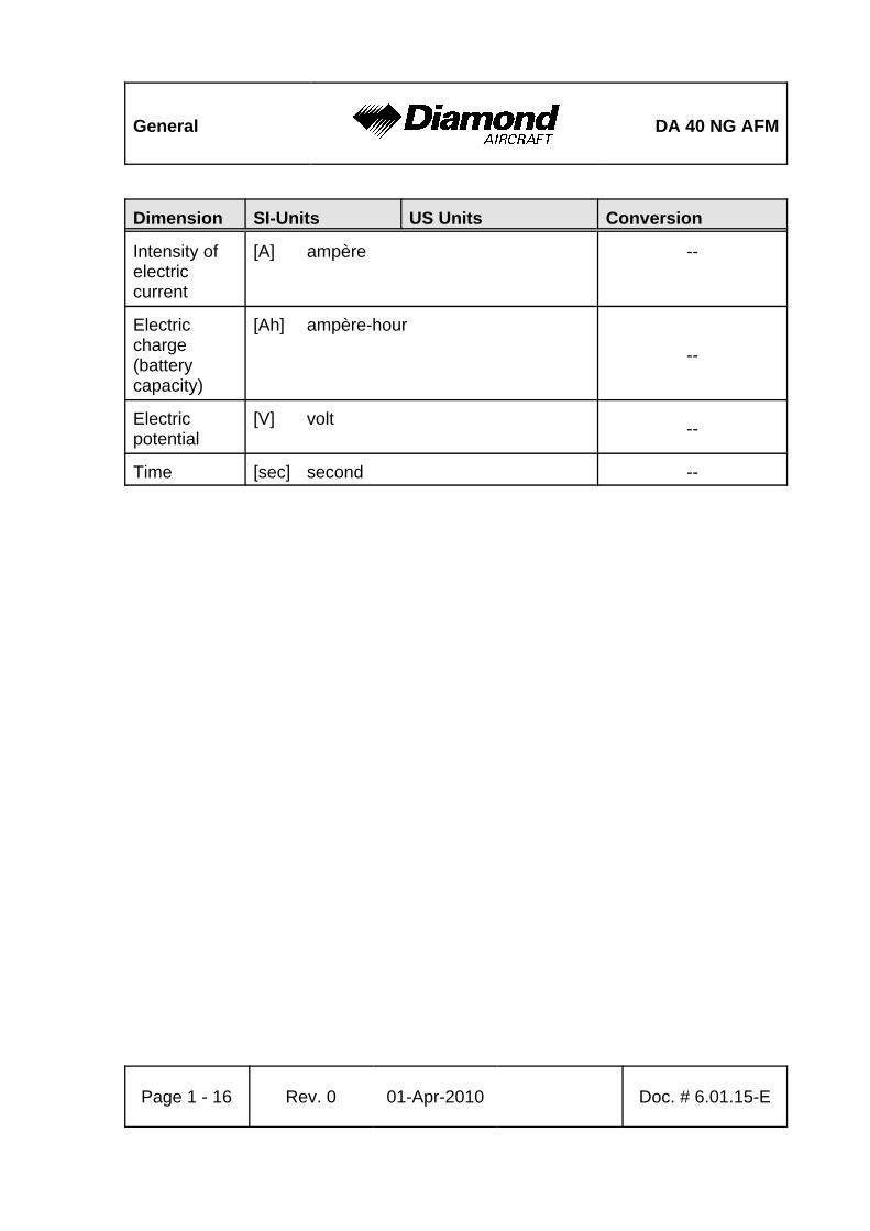
Intensity ofelectriccurrent
[A] ampère --
Electriccharge(batterycapacity)
[Ah] ampère-hour
--
Electricpotential
[V] volt --
Time [sec] second --

DA 40 NG AFM General
Doc. # 6.01.15-E Rev. 0 01-Apr-2010 Page 1 - 17
1.6.2 CONVERSION CHART LITER / US GALLON
Liter US Gallon US Gallon Liter
5 1.3 1 3.8
10 2.6 2 7.6
15 4.0 4 15.1
20 5.3 6 22.7
25 6.6 8 30.3
30 7.9 10 37.9
35 9.2 12 45.4
40 10.6 14 53.0
45 11.9 16 60.6
50 13.2 18 68.1
60 15.9 20 75.7
70 18.5 22 83.3
80 21.1 24 90.9
90 23.8 26 98.4
100 26.4 28 106.0
110 29.1 30 113.6
120 31.7 32 121.1
130 34.3 34 128.7
140 37.0 36 136.3
150 39.6 38 143.8
160 42.3 40 151.4
170 44.9 45 170.3
180 47.6 50 189.3
General DA 40 NG AFM
Page 1 - 18 Rev. 0 01-Apr-2010 Doc. # 6.01.15-E
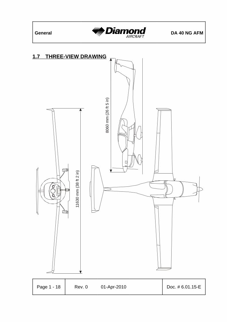
8060
mm
(26
ft 5
in)
1163
0 m
m (3
8 ft
2 in
)
1.7 THREE-VIEW DRAWING

DA 40 NG AFM General
Doc. # 6.01.15-E Rev. 0 01-Apr-2010 Page 1 - 19
1.8 G1000 AVIONICS SYSTEM
1. The G1000 Integrated Avionics System is a fully integrated flight, engine,communication, navigation and surveillance instrumentation system. The systemconsists of a Primary Flight Display (PFD), Multi-Function Display (MFD), audio panel,Air Data Computer (ADC), Attitude and Heading Reference System (AHRS), enginesensors and processing unit (GEA), and integrated avionics (GIA) containing VHFcommunications, VHF navigation, and GPS (Global Positioning System).
2. The primary function of the PFD is to provide attitude, heading, air data, navigation,and alerting information to the pilot. The PFD may also be used for flight planning.The primary function of the MFD is to provide engine information, mapping, terraininformation, autopilot operation, and for flight planning. The audio panel is used forselection of radios for transmitting and listening, intercom functions, and marker beaconfunctions.
3. The primary function of the VHF Communication portion of the G1000 is to enableexternal radio communication. The primary function of the VOR/ILS Receiver portionof the equipment is to receive and demodulate VOR, Localizer, and Glide Slope signals.The primary function of the GPS portion of the system is to acquire signals from theGPS satellites, recover orbital data, make range and Doppler measurements, andprocess this information in real-time to obtain the user's position, velocity, and time.
4. Provided a Garmin G1000 GPS receiver is receiving adequate usable signals, it hasbeen demonstrated capable of and has been shown to meet the accuracy specificationsfor:
(a) VFR/IFR enroute, oceanic, terminal, and non-precision instrument approach (GPS,Loran-C, VOR, VOR-DME, TACAN, NDB, NDB-DME, RNAV) operation within theU.S. National Airspace System in accordance with AC 20-138A.

General DA 40 NG AFM
Page 1 - 20 Rev. 0 01-Apr-2010 Doc. # 6.01.15-E
(b) RNAV (GPS) Approaches - The G1000 GPS meets the requirements ofAC 20-138(A) for GPS based RNAV approaches. This includes RNAV approacheslabeled as RNAV (GPS), provided GPS sensor data is valid.
(c) The system meets the accuracy of RNP5 airspace (BRNAV) requirements ofAC 90-96 and in accordance with AC 20-138A, EASA AMC 20-4, and FAA Order8110.60 for oceanic and remote airspace operations, provided it is receiving usablenavigation information from the GPS receiver.
Navigation is accomplished using the WGS-84 (NAD-83) coordinate reference datum.GPS navigation data is based upon use of only the GPS operated by the United Statesof America.

DA 40 NG AFM General
Doc. # 6.01.15-E Rev. 0 01-Apr-2010 Page 1 - 21
1.9 SOURCE DOCUMENTATION
This section lists documents, manuals and other literature that were used as sources forthe Airplane Flight Manual, and indicates the respective publisher. However, only theinformation given in the Airplane Flight Manual is valid.
1.9.1 ENGINE AND ENGINE INSTRUMENTS
Address: Austro Engine GmbHRudolf Diesel-Str. 11 A-2700 Wiener NeustadtAUSTRIA
Phone: +43-2622-23 000 Fax: +43-2622-23 000 - 2711 Internet: www.austroengine.at
Documents: Operation Manual AE300,E4.01.01 Rev. 3 or later
Maintenance Manual AE300, E4.08.04 Rev. 3 or later
Installation Manual AE300,E4.02.01 Rev. 7 or later
General DA 40 NG AFM
Page 1 - 22 Rev. 0 01-Apr-2010 Doc. # 6.01.15-E
1.9.2 PROPELLER
Address: mt-propellerAirport Straubing WallmühleD-94348 ATTINGGERMANY
Phone: +49-9429-9409-0E-mail: [email protected]: www.mt-propeller.de
Documents: E-124, Operation and Installation ManualHydraulically controlled variable pitch propellerMTV -5, -6, -9, -11, -12, -14, -15, -16, -21, -22, -25
1.9.3 AVIONICS SYSTEM
Address: Garmin International, Inc.1200 East 151st StreetOlathe, Kansas 66062USA
Phone: +1-(913)-3978200
Fax: +1-(913)-3978282
Website: www.garmin.com
Documents: G1000 Cockpit Reference GuideP/N 190-00953-00, Rev. 0 or later
G1000 Pilot´s GuideP/N 190-00952-00, Rev. 0 or later

DA 40 NG AFMOperation
Limitations
Doc. # 6.01.15-E Rev. 0 01-Apr-2010 EASAapproved Page 2 - 1
CHAPTER 2OPERATING LIMITATIONS
Page2.1 INTRODUCTION . . . . . . . . . . . . . . . . . . . . . . . . . . . . . . . . . . . . . . . 2-22.2 AIRSPEED . . . . . . . . . . . . . . . . . . . . . . . . . . . . . . . . . . . . . . . . . . . 2-32.3 AIRSPEED INDICATOR MARKINGS . . . . . . . . . . . . . . . . . . . . . . . 2-42.4 POWER-PLANT LIMITATIONS . . . . . . . . . . . . . . . . . . . . . . . . . . . 2-52.5 ENGINE INSTRUMENT MARKINGS . . . . . . . . . . . . . . . . . . . . . . . 2-92.6 WARNING, CAUTION AND STATUS LIGHTS . . . . . . . . . . . . . . . 2-102.7 MASS (WEIGHT) . . . . . . . . . . . . . . . . . . . . . . . . . . . . . . . . . . . . . 2-142.8 CENTER OF GRAVITY . . . . . . . . . . . . . . . . . . . . . . . . . . . . . . . . . 2-162.9 APPROVED MANEUVERS . . . . . . . . . . . . . . . . . . . . . . . . . . . . . . 2-172.10 MANEUVERING LOAD FACTORS . . . . . . . . . . . . . . . . . . . . . . . . 2-182.11 OPERATING ALTITUDE . . . . . . . . . . . . . . . . . . . . . . . . . . . . . . . . 2-192.12 FLIGHT CREW . . . . . . . . . . . . . . . . . . . . . . . . . . . . . . . . . . . . . . . 2-192.13 KINDS OF OPERATION . . . . . . . . . . . . . . . . . . . . . . . . . . . . . . . . 2-202.14 FUEL . . . . . . . . . . . . . . . . . . . . . . . . . . . . . . . . . . . . . . . . . . . . . . . 2-242.15 LIMITATION PLACARDS . . . . . . . . . . . . . . . . . . . . . . . . . . . . . . . 2-252.16 OTHER LIMITATIONS . . . . . . . . . . . . . . . . . . . . . . . . . . . . . . . . . 2-31
2.16.1 TEMPERATURE . . . . . . . . . . . . . . . . . . . . . . . . . . . . . . . . 2-312.16.2 BATTERY CHARGE . . . . . . . . . . . . . . . . . . . . . . . . . . . . . 2-312.16.3 EMERGENCY SWITCH . . . . . . . . . . . . . . . . . . . . . . . . . . 2-312.16.4 DOOR LOCKING DEVICE . . . . . . . . . . . . . . . . . . . . . . . . 2-312.16.5 ELECTRONIC EQUIPMENT . . . . . . . . . . . . . . . . . . . . . . . 2-322.16.6 SMOKING . . . . . . . . . . . . . . . . . . . . . . . . . . . . . . . . . . . . . 2-322.16.7 GARMIN G1000 AVIONICS SYSTEM . . . . . . . . . . . . . . . 2-332.16.8 AUTOPILOT LIMITATIONS . . . . . . . . . . . . . . . . . . . . . . . 2-38
Operation
LimitationsDA 40 NG AFM
Page 2 - 2 Rev. 0 01-Apr-2010 EASAapproved Doc. # 6.01.15-E
2.1 INTRODUCTION
Chapter 2 of this Airplane Flight Manual includes operating limitations, instrumentmarkings, and placards necessary for the safe operation of the airplane, its power-plant,standard systems and standard equipment.
The limitations included in this Chapter are approved.
WARNINGOperation of the airplane outside of the approved operatinglimitations is not permissible.
DA 40 NG AFMOperation
Limitations
Doc. # 6.01.15-E Rev. 0 01-Apr-2010 EASAapproved Page 2 - 3
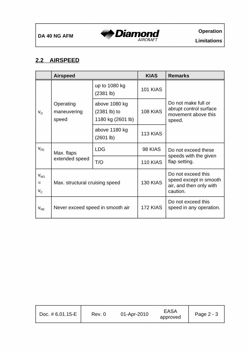
2.2 AIRSPEED
Airspeed KIAS Remarks
vO
Operatingmaneuveringspeed
up to 1080 kg(2381 lb)
101 KIAS
Do not make full orabrupt control surfacemovement above thisspeed.
above 1080 kg(2381 lb) to1180 kg (2601 lb)
108 KIAS
above 1180 kg(2601 lb)
113 KIAS
vFEMax. flapsextended speed
LDG 98 KIAS Do not exceed thesespeeds with the givenflap setting.T/O 110 KIAS
vNO
= vC
Max. structural cruising speed 130 KIAS
Do not exceed thisspeed except in smoothair, and then only withcaution.
vNE Never exceed speed in smooth air 172 KIASDo not exceed thisspeed in any operation.
Operation
LimitationsDA 40 NG AFM
Page 2 - 4 Rev. 0 01-Apr-2010 EASAapproved Doc. # 6.01.15-E
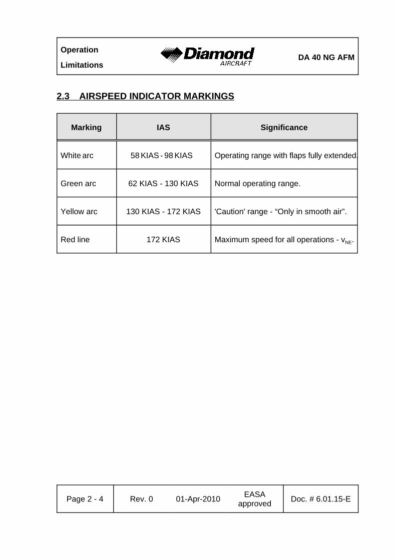
2.3 AIRSPEED INDICATOR MARKINGS
Marking IAS Significance
White arc 58 KIAS - 98 KIAS Operating range with flaps fully extended.
Green arc 62 KIAS - 130 KIAS Normal operating range.
Yellow arc 130 KIAS - 172 KIAS 'Caution' range - “Only in smooth air”.
Red line 172 KIAS Maximum speed for all operations - vNE.
DA 40 NG AFMOperation
Limitations
Doc. # 6.01.15-E Rev. 0 01-Apr-2010 EASAapproved Page 2 - 5
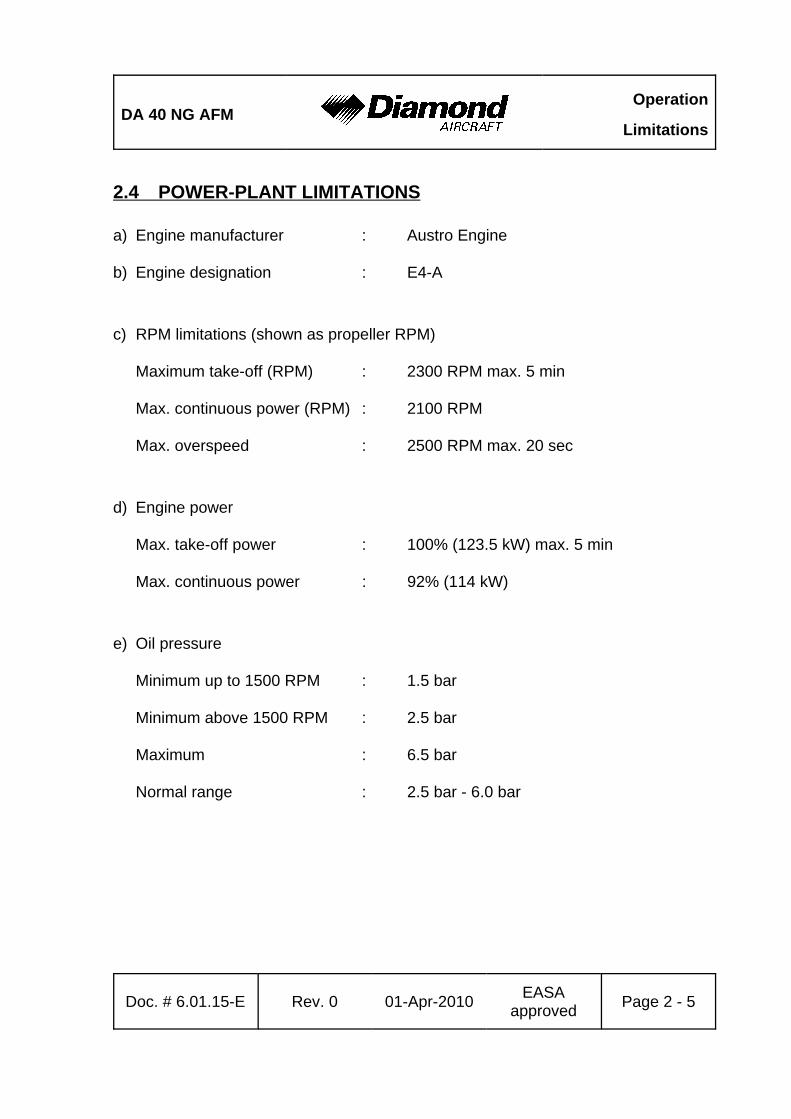
2.4 POWER-PLANT LIMITATIONS
a) Engine manufacturer : Austro Engine
b) Engine designation : E4-A
c) RPM limitations (shown as propeller RPM)
Maximum take-off (RPM) : 2300 RPM max. 5 min
Max. continuous power (RPM) : 2100 RPM
Max. overspeed : 2500 RPM max. 20 sec
d) Engine power
Max. take-off power : 100% (123.5 kW) max. 5 min
Max. continuous power : 92% (114 kW)
e) Oil pressure
Minimum up to 1500 RPM : 1.5 bar
Minimum above 1500 RPM : 2.5 bar
Maximum : 6.5 bar
Normal range : 2.5 bar - 6.0 bar
Operation
LimitationsDA 40 NG AFM
Page 2 - 6 Rev. 0 01-Apr-2010 EASAapproved Doc. # 6.01.15-E
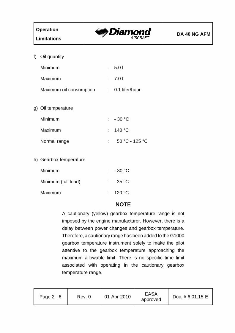
f) Oil quantity
Minimum : 5.0 l
Maximum : 7.0 l
Maximum oil consumption : 0.1 liter/hour
g) Oil temperature
Minimum : - 30 °C
Maximum : 140 °C
Normal range : 50 °C - 125 °C
h) Gearbox temperature
Minimum : - 30 °C
Minimum (full load) : 35 °C
Maximum : 120 °C
NOTEA cautionary (yellow) gearbox temperature range is notimposed by the engine manufacturer. However, there is adelay between power changes and gearbox temperature.Therefore, a cautionary range has been added to the G1000gearbox temperature instrument solely to make the pilotattentive to the gearbox temperature approaching themaximum allowable limit. There is no specific time limitassociated with operating in the cautionary gearboxtemperature range.
DA 40 NG AFMOperation
Limitations
Doc. # 6.01.15-E Rev. 0 01-Apr-2010 EASAapproved Page 2 - 7
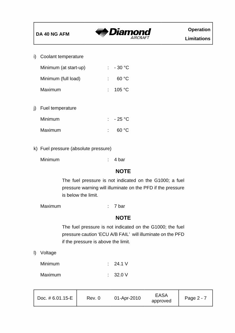
i) Coolant temperature
Minimum (at start-up) : - 30 °C
Minimum (full load) : 60 °C
Maximum : 105 °C
j) Fuel temperature
Minimum : - 25 °C
Maximum : 60 °C
k) Fuel pressure (absolute pressure)
Minimum : 4 bar
NOTEThe fuel pressure is not indicated on the G1000; a fuelpressure warning will illuminate on the PFD if the pressureis below the limit.
Maximum : 7 bar
NOTEThe fuel pressure is not indicated on the G1000; the fuelpressure caution ‘ECU A/B FAIL’ will illuminate on the PFDif the pressure is above the limit.
l) Voltage
Minimum : 24.1 V
Maximum : 32.0 V
Operation
LimitationsDA 40 NG AFM
Page 2 - 8 Rev. 0 01-Apr-2010 EASAapproved Doc. # 6.01.15-E
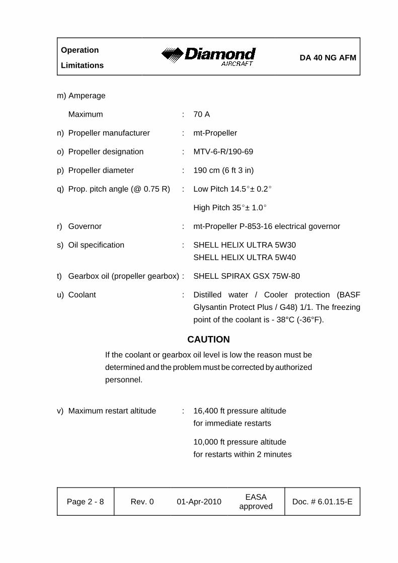
m) Amperage
Maximum : 70 A
n) Propeller manufacturer : mt-Propeller
o) Propeller designation : MTV-6-R/190-69
p) Propeller diameter : 190 cm (6 ft 3 in)
q) Prop. pitch angle (@ 0.75 R) : Low Pitch 14.5E± 0.2E
High Pitch 35E± 1.0E
r) Governor : mt-Propeller P-853-16 electrical governor
s) Oil specification : SHELL HELIX ULTRA 5W30SHELL HELIX ULTRA 5W40
t) Gearbox oil (propeller gearbox) : SHELL SPIRAX GSX 75W-80
u) Coolant : Distilled water / Cooler protection (BASFGlysantin Protect Plus / G48) 1/1. The freezingpoint of the coolant is - 38°C (-36°F).
CAUTIONIf the coolant or gearbox oil level is low the reason must bedetermined and the problem must be corrected by authorizedpersonnel.
v) Maximum restart altitude : 16,400 ft pressure altitude for immediate restarts
10,000 ft pressure altitude for restarts within 2 minutes
DA 40 NG AFMOperation
Limitations
Doc. # 6.01.15-E Rev. 0 01-Apr-2010 EASAapproved Page 2 - 9
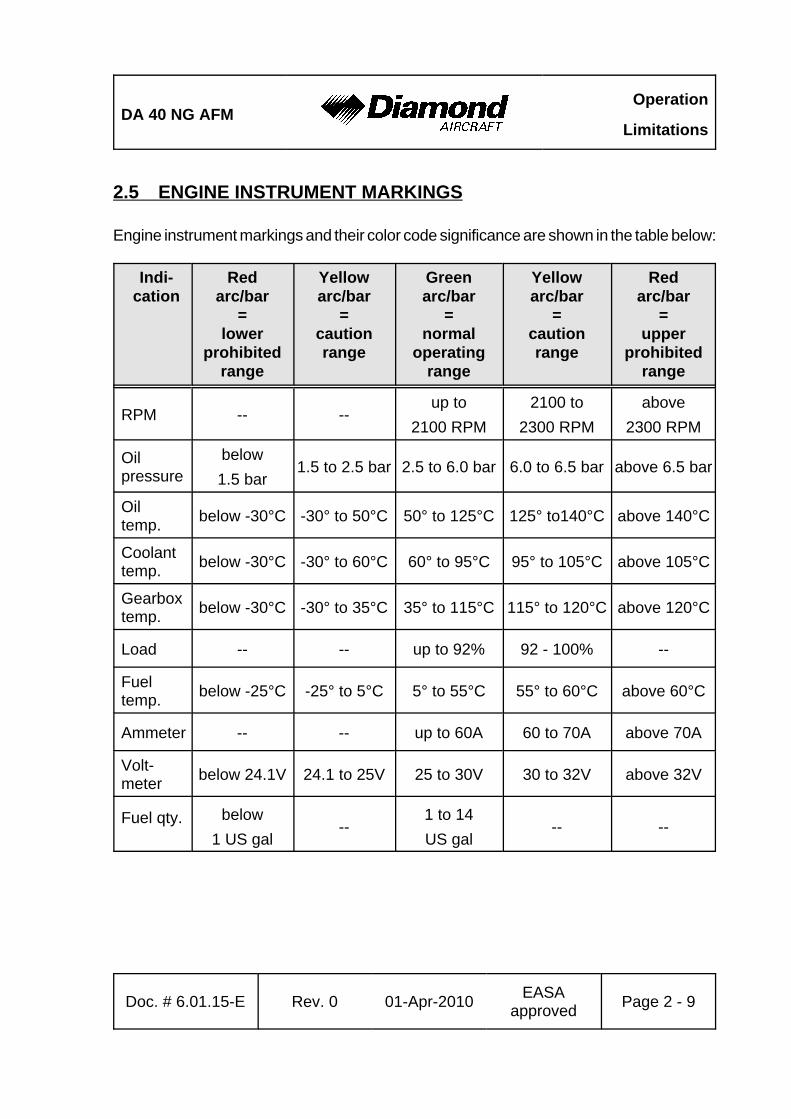
2.5 ENGINE INSTRUMENT MARKINGS
Engine instrument markings and their color code significance are shown in the table below:
Indi-cation
Redarc/bar
=lower
prohibitedrange
Yellowarc/bar
=cautionrange
Greenarc/bar
=normal
operatingrange
Yellowarc/bar
=cautionrange
Redarc/bar
=upper
prohibitedrange
RPM -- --up to
2100 RPM2100 to
2300 RPMabove
2300 RPM
Oilpressure
below1.5 bar
1.5 to 2.5 bar 2.5 to 6.0 bar 6.0 to 6.5 bar above 6.5 bar
Oiltemp. below -30°C -30° to 50°C 50° to 125°C 125° to140°C above 140°C
Coolanttemp. below -30°C -30° to 60°C 60° to 95°C 95° to 105°C above 105°C
Gearboxtemp. below -30°C -30° to 35°C 35° to 115°C 115° to 120°C above 120°C
Load -- -- up to 92% 92 - 100% --
Fueltemp. below -25°C -25° to 5°C 5° to 55°C 55° to 60°C above 60°C
Ammeter -- -- up to 60A 60 to 70A above 70A
Volt-meter below 24.1V 24.1 to 25V 25 to 30V 30 to 32V above 32V
Fuel qty. below1 US gal
--1 to 14US gal
-- --

Operation
LimitationsDA 40 NG AFM
Page 2 - 10 Rev. 0 01-Apr-2010 EASAapproved Doc. # 6.01.15-E
2.6 WARNING, CAUTION AND STATUS LIGHTS
The following tables show the color and significance of the warning, caution and advisoryalerts lights on the G1000.
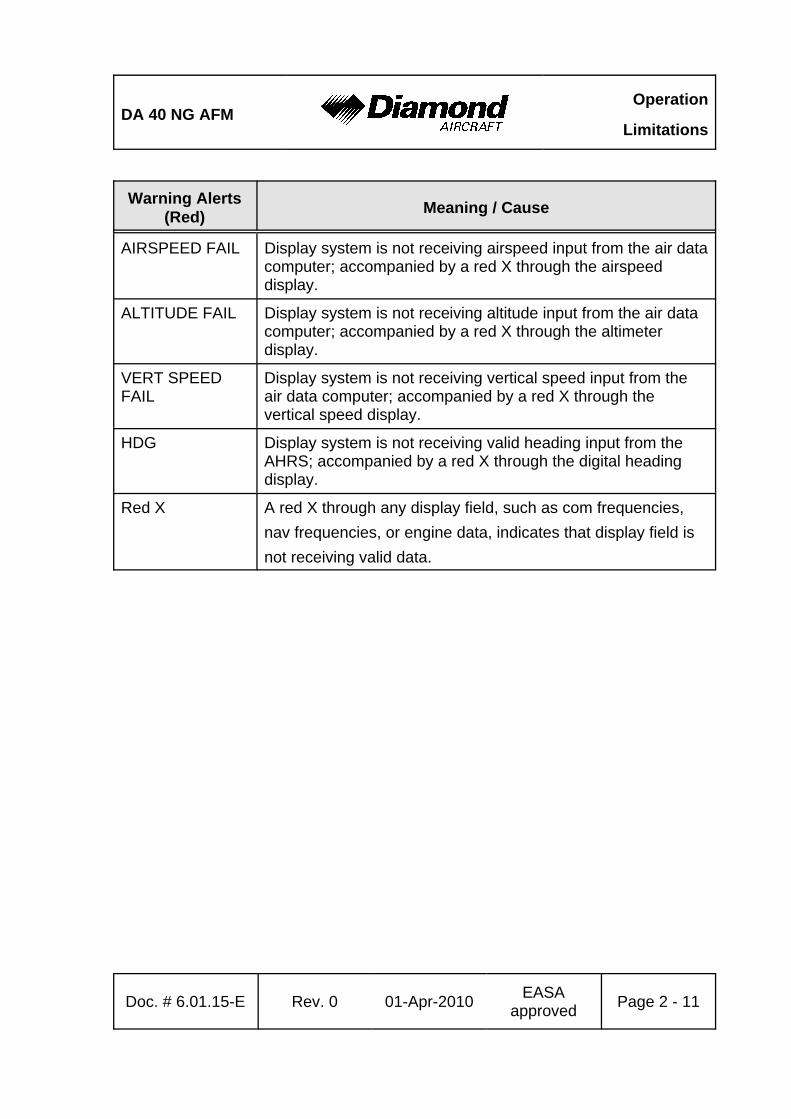
Color and Significance of the Warning Lights (Red)
Warning Alerts(Red) Meaning / Cause
WARNING One of the warnings listed below is being indicated.
ENG TEMPEngine coolant temperature is in the upper red range(too high / > 105 °C).
OIL TEMPEngine oil temperature is in the upper red range
(too high / > 140 °C).
OIL PRESEngine oil pressure is in the lower red range
(too low / < 1.5 bar).
L/R FUEL TEMP Fuel temperature is in the upper red range
(too high / > 60 °C).
GBOX TEMP Engine gearbox temperature is in the upper red range
(too high / > 120 °C).
FUEL PRESS Engine fuel pressure is low.
ALTN AMPS Engine alternator output is in the upper red range
(too high / > 70 A).
ALTN FAIL Engine alternator has failed.
STARTER Engine starter is engaged.
DOOR OPEN Canopy and/or Rear Door are/is not closed and locked.
ATTITUDE FAIL Display system is not receiving attitude reference informationfrom the AHRS; accompanied by the removal of sky/groundpresentation and a red X over the attitude area.
DA 40 NG AFMOperation
Limitations
Warning Alerts(Red) Meaning / Cause
Doc. # 6.01.15-E Rev. 0 01-Apr-2010 EASAapproved Page 2 - 11
AIRSPEED FAIL Display system is not receiving airspeed input from the air datacomputer; accompanied by a red X through the airspeeddisplay.
ALTITUDE FAIL Display system is not receiving altitude input from the air datacomputer; accompanied by a red X through the altimeterdisplay.
VERT SPEEDFAIL
Display system is not receiving vertical speed input from theair data computer; accompanied by a red X through thevertical speed display.
HDG Display system is not receiving valid heading input from theAHRS; accompanied by a red X through the digital headingdisplay.
Red X A red X through any display field, such as com frequencies,nav frequencies, or engine data, indicates that display field isnot receiving valid data.
Operation
LimitationsDA 40 NG AFM
Page 2 - 12 Rev. 0 01-Apr-2010 EASAapproved Doc. # 6.01.15-E
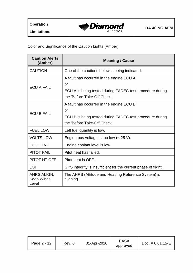
Color and Significance of the Caution Lights (Amber)
Caution Alerts(Amber) Meaning / Cause
CAUTION One of the cautions below is being indicated.
ECU A FAIL
A fault has occurred in the engine ECU Aor
ECU A is being tested during FADEC-test procedure duringthe 'Before Take-Off Check'.
ECU B FAIL
A fault has occurred in the engine ECU B or
ECU B is being tested during FADEC-test procedure duringthe 'Before Take-Off Check'.
FUEL LOW Left fuel quantity is low.
VOLTS LOW Engine bus voltage is too low (< 25 V).
COOL LVL Engine coolant level is low.
PITOT FAIL Pitot heat has failed.
PITOT HT OFF Pitot heat is OFF.
LOI GPS integrity is insufficient for the current phase of flight.
AHRS ALIGN:Keep WingsLevel
The AHRS (Attitude and Heading Reference System) isaligning.
DA 40 NG AFMOperation
Limitations
Doc. # 6.01.15-E Rev. 0 01-Apr-2010 EASAapproved Page 2 - 13
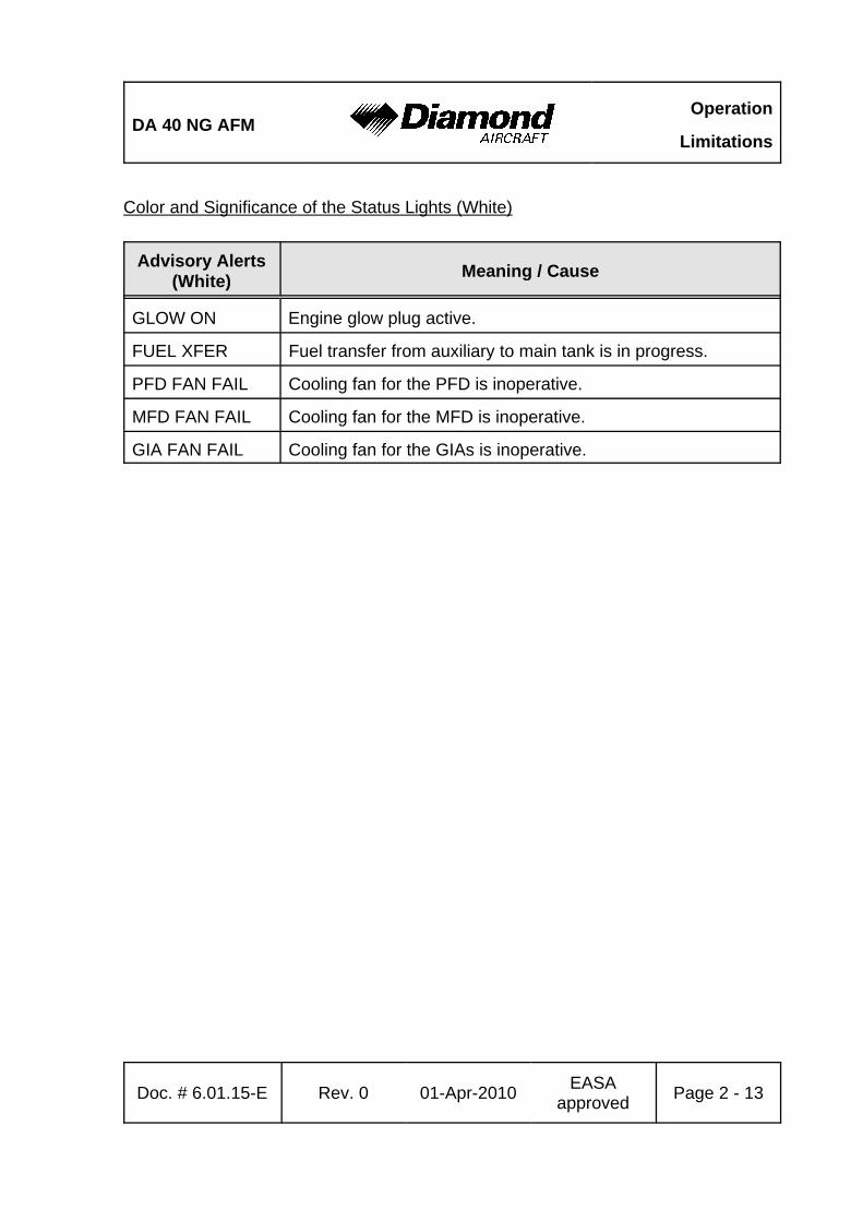
Color and Significance of the Status Lights (White)
Advisory Alerts(White) Meaning / Cause
GLOW ON Engine glow plug active.
FUEL XFER Fuel transfer from auxiliary to main tank is in progress.
PFD FAN FAIL Cooling fan for the PFD is inoperative.
MFD FAN FAIL Cooling fan for the MFD is inoperative.
GIA FAN FAIL Cooling fan for the GIAs is inoperative.

Operation
LimitationsDA 40 NG AFM
Page 2 - 14 Rev. 0 01-Apr-2010 EASAapproved Doc. # 6.01.15-E
2.7 MASS (WEIGHT)
Maximum take-off mass : 1280 kg (2822 lb)Maximum landing mass : 1216 kg (2681 lb)
Max. load in baggage compartment : 30 kg (66 lb)Max. load in baggage tube compartment : 5 kg (11 lb)Max. load in baggage tray (if OÄM 40-164 is installed, extendedbaggage compartment) : 45 kg (100 lb)
Minimum flight mass : 940 kg (2072 lb)Maximum zero fuel mass : 1200 kg (2646 lb)
WARNINGExceeding the mass limits will lead to an overstressing of theairplane as well as to a degradation of flight characteristicsand flight performance.
NOTEThe maximum landing mass is the highest mass for landingconditions at the maximum descent velocity. This conditionwas used in the strength calculations to determine the landinggear loads during a particularly hard landing.

DA 40 NG AFMOperation
Limitations
Doc. # 6.01.15-E Rev. 0 01-Apr-2010 EASAapproved Page 2 - 15
NOTEIn some countries the beginning of a flight is defined bystarting the engine. In those countries a maximum ramp mass4 kg (9 lb) above the maximum take-off mass is approved.At the time of lift-off the maximum permitted take-off massmust not be exceeded.
NOTEThe maximum zero fuel mass is the highest mass with emptyfuel tanks.
Operation
LimitationsDA 40 NG AFM
Page 2 - 16 Rev. 0 01-Apr-2010 EASAapproved Doc. # 6.01.15-E
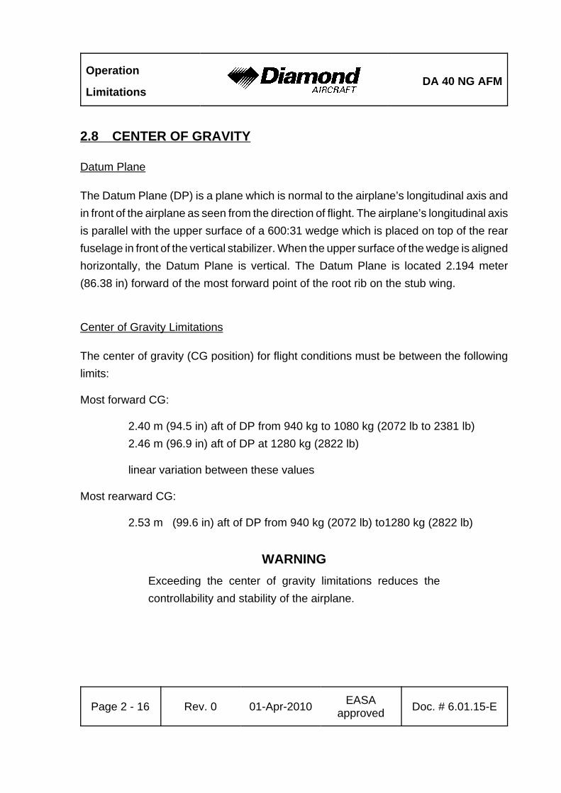
2.8 CENTER OF GRAVITY
Datum Plane
The Datum Plane (DP) is a plane which is normal to the airplane’s longitudinal axis andin front of the airplane as seen from the direction of flight. The airplane’s longitudinal axisis parallel with the upper surface of a 600:31 wedge which is placed on top of the rearfuselage in front of the vertical stabilizer. When the upper surface of the wedge is alignedhorizontally, the Datum Plane is vertical. The Datum Plane is located 2.194 meter(86.38 in) forward of the most forward point of the root rib on the stub wing.
Center of Gravity Limitations
The center of gravity (CG position) for flight conditions must be between the followinglimits:
Most forward CG:
2.40 m (94.5 in) aft of DP from 940 kg to 1080 kg (2072 lb to 2381 lb)2.46 m (96.9 in) aft of DP at 1280 kg (2822 lb)
linear variation between these values
Most rearward CG:
2.53 m (99.6 in) aft of DP from 940 kg (2072 lb) to1280 kg (2822 lb)
WARNINGExceeding the center of gravity limitations reduces thecontrollability and stability of the airplane.
DA 40 NG AFMOperation
Limitations
Doc. # 6.01.15-E Rev. 0 01-Apr-2010 EASAapproved Page 2 - 17
2.9 APPROVED MANEUVERS
The airplane is to be operated in the Normal Category in accordance with JAR 23.
Approved Maneuvers
1) All normal flight maneuvers;
2) Stalling (with the exception of dynamic stalling); and
3) Lazy Eights, Chandelles, as well as steep turns and similar maneuvers, in whichan angle of bank of not more than 60° is attained.
CAUTIONAerobatics, spinning, and flight maneuvers with more than60° of bank are not permitted in the Normal Category.
CAUTIONIntentional negative g-maneuvers are not permitted.
Operation
LimitationsDA 40 NG AFM
Page 2 - 18 Rev. 0 01-Apr-2010 EASAapproved Doc. # 6.01.15-E
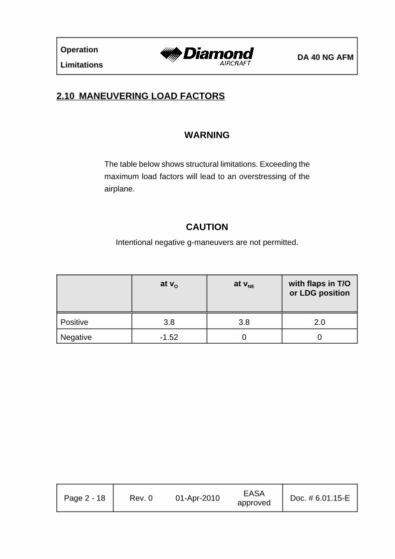
2.10 MANEUVERING LOAD FACTORS
WARNING
The table below shows structural limitations. Exceeding themaximum load factors will lead to an overstressing of theairplane.
CAUTIONIntentional negative g-maneuvers are not permitted.
at vO at vNE with flaps in T/Oor LDG position
Positive 3.8 3.8 2.0
Negative -1.52 0 0
DA 40 NG AFMOperation
Limitations
Doc. # 6.01.15-E Rev. 0 01-Apr-2010 EASAapproved Page 2 - 19
2.11 OPERATING ALTITUDE
The maximum operating altitude is 16,400 ft (5,000 m) pressure altitude.
2.12 FLIGHT CREW
Minimum crew : 1 (one person)
Maximum number of occupants : 4 (four persons)
Operation
LimitationsDA 40 NG AFM
Page 2 - 20 Rev. 0 01-Apr-2010 EASAapproved Doc. # 6.01.15-E
2.13 KINDS OF OPERATION
Provided that national operational requirements are met, the following kinds of operationare approved:
• Daytime flights according to Visual Flight Rules (VFR)
• With the appropriate equipment: night flights according to Visual Flight Rules(NVFR)
• With the appropriate equipment: flights according to Instrument Flight Rules (IFR)
• Take-off and landing on paved surfaces
• Take-off and landing on unpaved surfaces
Flights into known or forecast icing conditions are prohibited.
Flights into known thunderstorms are prohibited.
Minimum Operational Equipment (Serviceable)
The following table lists the minimum serviceable equipment required by JAR-23. Additionalminimum equipment for the intended operation may be required by national operatingrules and also depends on the route to be flown.
NOTEMany of the items of minimum equipment listed in thefollowing table are integrated in the G1000.
DA 40 NG AFMOperation
Limitations
Doc. # 6.01.15-E Rev. 0 01-Apr-2010 EASAapproved Page 2 - 21
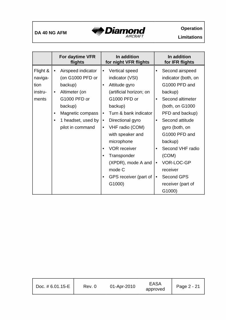
For daytime VFRflights
In additionfor night VFR flights
In additionfor IFR flights
Flight &naviga-tioninstru-ments
• Airspeed indicator(on G1000 PFD orbackup)
• Altimeter (onG1000 PFD orbackup)
• Magnetic compass• 1 headset, used by
pilot in command
• Vertical speedindicator (VSI)
• Attitude gyro(artificial horizon; onG1000 PFD orbackup)
• Turn & bank indicator• Directional gyro• VHF radio (COM)
with speaker andmicrophone
• VOR receiver• Transponder
(XPDR), mode A andmode C
• GPS receiver (part ofG1000)
• Second airspeedindicator (both, onG1000 PFD andbackup)
• Second altimeter(both, on G1000PFD and backup)
• Second attitudegyro (both, onG1000 PFD andbackup)
• Second VHF radio(COM)
• VOR-LOC-GPreceiver
• Second GPSreceiver (part ofG1000)

Operation
LimitationsDA 40 NG AFM
For daytime VFRflights
In additionfor night VFR flights
In additionfor IFR flights
Page 2 - 22 Rev. 0 01-Apr-2010 EASAapproved Doc. # 6.01.15-E
Engineinstru-ments
• Fuel qty.• Oil press.• Oil temp.• Coolant temp.• Coolant level
indicator• Gearbox temp.• Load• Prop. RPM• Fuel temp. left &
right tank• Fuel flow• Fuel pressure
warning• ECU CAUTION• ECU A/B FAIL
• Ammeter• Voltmeter
Lighting • Position lights• Strobe lights (anti
collision lights)• Landing light• Instrument lighting• Flood light• Flashlight
DA 40 NG AFMOperation
Limitations
For daytime VFRflights
In additionfor night VFR flights
In additionfor IFR flights
Doc. # 6.01.15-E Rev. 0 01-Apr-2010 EASAapproved Page 2 - 23
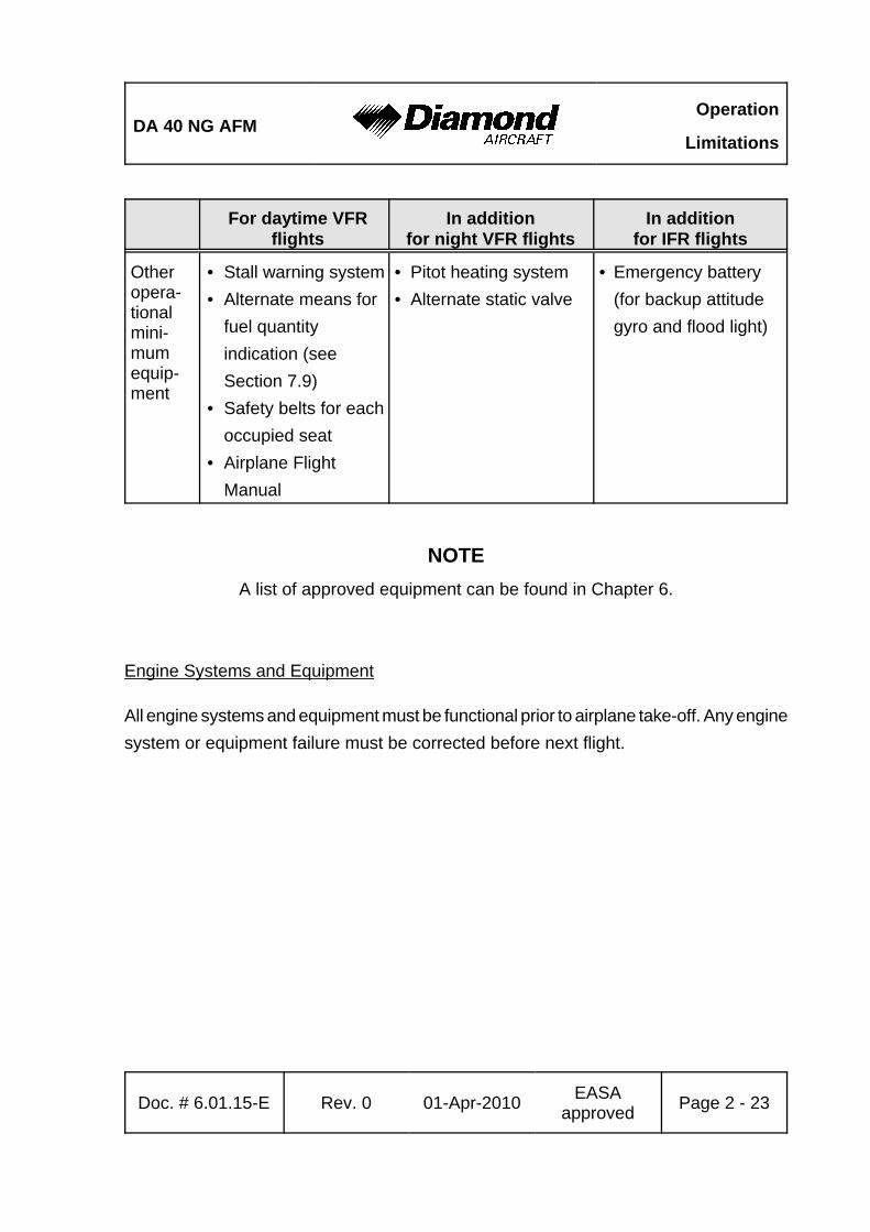
Otheropera-tionalmini-mumequip-ment
• Stall warning system• Alternate means for
fuel quantityindication (seeSection 7.9)
• Safety belts for eachoccupied seat
• Airplane FlightManual
• Pitot heating system• Alternate static valve
• Emergency battery(for backup attitudegyro and flood light)
NOTEA list of approved equipment can be found in Chapter 6.
Engine Systems and Equipment
All engine systems and equipment must be functional prior to airplane take-off. Any enginesystem or equipment failure must be corrected before next flight.
Operation
LimitationsDA 40 NG AFM
Page 2 - 24 Rev. 0 01-Apr-2010 EASAapproved Doc. # 6.01.15-E
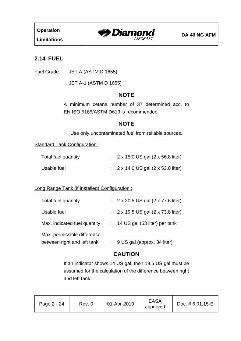
2.14 FUEL
Fuel Grade: JET A (ASTM D 1655),
JET A-1 (ASTM D 1655)
NOTEA minimum cetane number of 37 determined acc. toEN ISO 5165/ASTM D613 is recommended.
NOTEUse only uncontaminated fuel from reliable sources.
Standard Tank Configuration:
Total fuel quantity : 2 x 15.0 US gal (2 x 56.8 liter)
Usable fuel : 2 x 14.0 US gal (2 x 53.0 liter)
Long Range Tank (if installed) Configuration :
Total fuel quantity : 2 x 20.5 US gal (2 x 77.6 liter)
Usable fuel : 2 x 19.5 US gal (2 x 73.8 liter)
Max. indicated fuel quantity : 14 US gal (53 liter) per tank
Max. permissible differencebetween right and left tank : 9 US gal (approx. 34 liter)
CAUTIONIf an indicator shows 14 US gal, then 19.5 US gal must beassumed for the calculation of the difference between rightand left tank.
DA 40 NG AFMOperation
Limitations
Doc. # 6.01.15-E Rev. 0 01-Apr-2010 EASAapproved Page 2 - 25
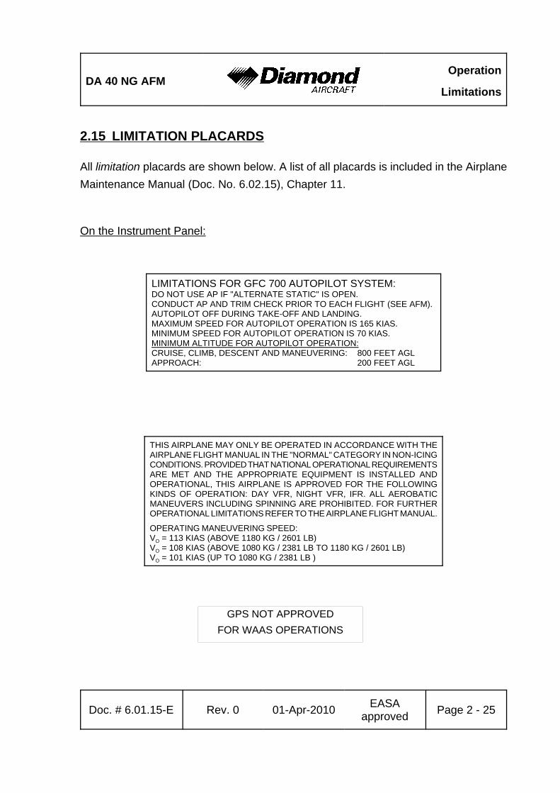
GPS NOT APPROVEDFOR WAAS OPERATIONS
2.15 LIMITATION PLACARDS
All limitation placards are shown below. A list of all placards is included in the AirplaneMaintenance Manual (Doc. No. 6.02.15), Chapter 11.
On the Instrument Panel:
LIMITATIONS FOR GFC 700 AUTOPILOT SYSTEM:DO NOT USE AP IF "ALTERNATE STATIC" IS OPEN.CONDUCT AP AND TRIM CHECK PRIOR TO EACH FLIGHT (SEE AFM).AUTOPILOT OFF DURING TAKE-OFF AND LANDING.MAXIMUM SPEED FOR AUTOPILOT OPERATION IS 165 KIAS.MINIMUM SPEED FOR AUTOPILOT OPERATION IS 70 KIAS.MINIMUM ALTITUDE FOR AUTOPILOT OPERATION: CRUISE, CLIMB, DESCENT AND MANEUVERING: 800 FEET AGLAPPROACH: 200 FEET AGL
THIS AIRPLANE MAY ONLY BE OPERATED IN ACCORDANCE WITH THEAIRPLANE FLIGHT MANUAL IN THE "NORMAL" CATEGORY IN NON-ICINGCONDITIONS. PROVIDED THAT NATIONAL OPERATIONAL REQUIREMENTSARE MET AND THE APPROPRIATE EQUIPMENT IS INSTALLED ANDOPERATIONAL, THIS AIRPLANE IS APPROVED FOR THE FOLLOWINGKINDS OF OPERATION: DAY VFR, NIGHT VFR, IFR. ALL AEROBATICMANEUVERS INCLUDING SPINNING ARE PROHIBITED. FOR FURTHEROPERATIONAL LIMITATIONS REFER TO THE AIRPLANE FLIGHT MANUAL.
OPERATING MANEUVERING SPEED:VO = 113 KIAS (ABOVE 1180 KG / 2601 LB)VO = 108 KIAS (ABOVE 1080 KG / 2381 LB TO 1180 KG / 2601 LB)VO = 101 KIAS (UP TO 1080 KG / 2381 LB )
Operation
LimitationsDA 40 NG AFM
Page 2 - 26 Rev. 0 01-Apr-2010 EASAapproved Doc. # 6.01.15-E
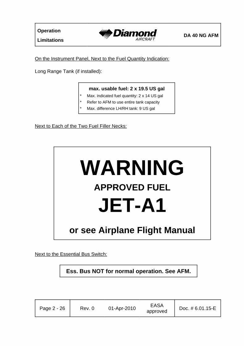
max. usable fuel: 2 x 19.5 US gal* Max. indicated fuel quantity: 2 x 14 US gal* Refer to AFM to use entire tank capacity* Max. difference LH/RH tank: 9 US gal
WARNINGAPPROVED FUEL
JET-A1or see Airplane Flight Manual
On the Instrument Panel, Next to the Fuel Quantity Indication:
Long Range Tank (if installed):
Next to Each of the Two Fuel Filler Necks:
Next to the Essential Bus Switch:
Ess. Bus NOT for normal operation. See AFM.

DA 40 NG AFMOperation
Limitations
Doc. # 6.01.15-E Rev. 0 01-Apr-2010 EASAapproved Page 2 - 27
OILSHELL HELIX
ULTRA
5W30or see Airplane Flight Manual
max.98 KIAS
max.110 KIAS
OFF
CAUTION: INTERMITTENT USEONLY (SEE AFM)
FUEL VALVEEMERGENCYNORMAL
In the Cowling, on the Door for the Oil Filler Neck:
Next to the Flap Selector Switch:
On the Fuel Valve:
Operation
LimitationsDA 40 NG AFM
Page 2 - 28 Rev. 0 01-Apr-2010 EASAapproved Doc. # 6.01.15-E
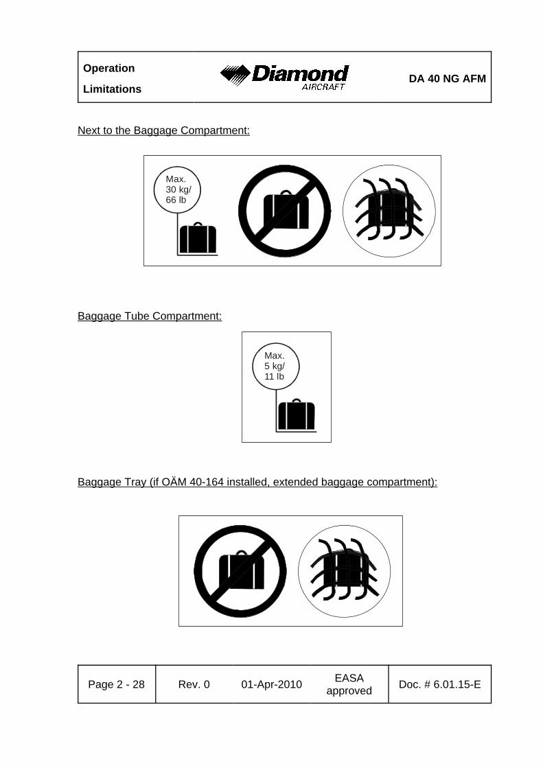
Max.30 kg/66 lb
Max.5 kg/11 lb
Next to the Baggage Compartment:
Baggage Tube Compartment:
Baggage Tray (if OÄM 40-164 installed, extended baggage compartment):
DA 40 NG AFMOperation
Limitations
Doc. # 6.01.15-E Rev. 0 01-Apr-2010 EASAapproved Page 2 - 29
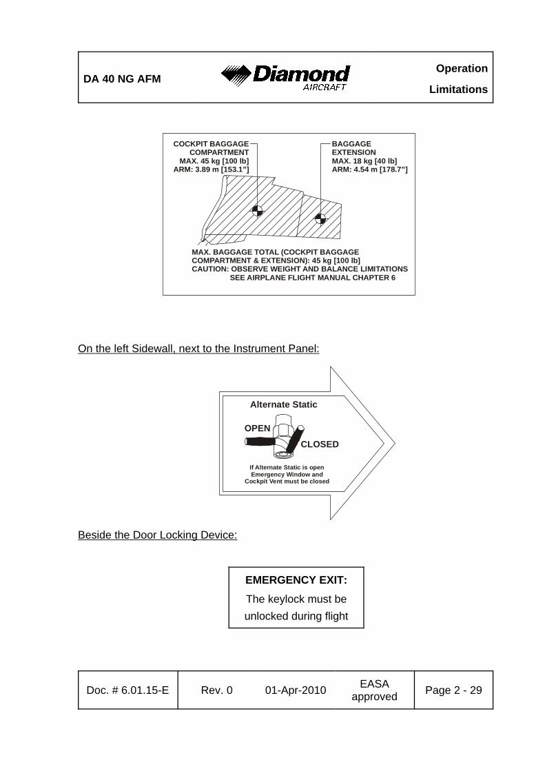
COCKPIT BAGGAGECOMPARTMENT
MAX. 45 kg [100 lb]ARM: 3.89 m [153.1”]
BAGGAGEEXTENSIONMAX. 18 kg [40 lb]ARM: 4.54 m [178.7”]
MAX. BAGGAGE TOTAL (COCKPIT BAGGAGECOMPARTMENT & EXTENSION): 45 kg [100 lb]CAUTION: OBSERVE WEIGHT AND BALANCE LIMITATIONS SEE AIRPLANE FLIGHT MANUAL CHAPTER 6
On the left Sidewall, next to the Instrument Panel:
Beside the Door Locking Device:
Alternate Static
OPEN
CLOSED
If Alternate Static is openEmergency Window and
Cockpit Vent must be closed
EMERGENCY EXIT:The keylock must beunlocked during flight
Operation
LimitationsDA 40 NG AFM
Page 2 - 30 Rev. 0 01-Apr-2010 EASAapproved Doc. # 6.01.15-E
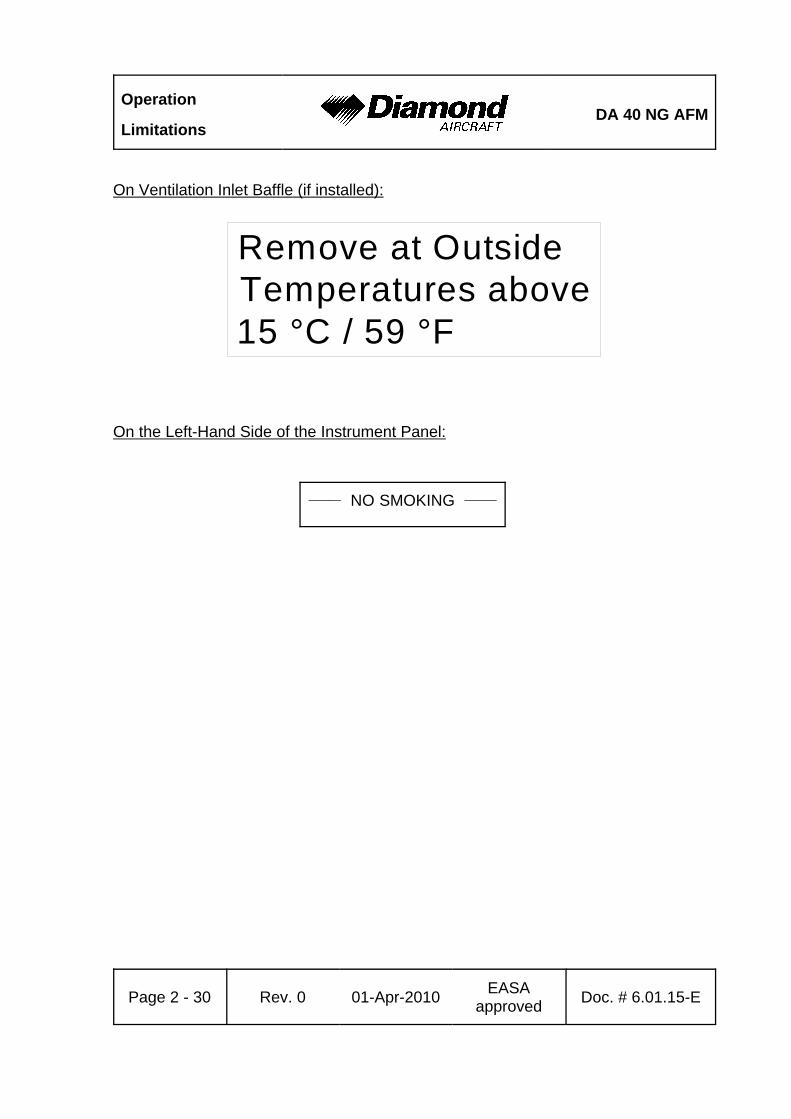
Remove at Outside Temperatures above15 °C / 59 °F
On Ventilation Inlet Baffle (if installed):
On the Left-Hand Side of the Instrument Panel:
______ NO SMOKING ______
DA 40 NG AFMOperation
Limitations
Doc. # 6.01.15-E Rev. 0 01-Apr-2010 EASAapproved Page 2 - 31
2.16 OTHER LIMITATIONS
2.16.1 TEMPERATURE
The airplane may only be operated when its temperature prior to operation is not lessthan -20 °C (-4 °F).
With the airplane cold soaked and its temperature below -20 °C (-4 °F) the use of anexternal pre-heater for the engine and pilot compartment prior to operation is mandatory.
The airplane may only be operated with the ventilation inlet baffle installed when theoutside air temperature at take-off does not exceed 15 EC (59 EF).
2.16.2 BATTERY CHARGE
Take-off for a Night VFR or IFR flight with an empty main battery is not permitted.
The use of an external power supply for engine starting with an empty airplane mainbattery is not permitted if the subsequent flight is intended to be a Night VFR or an IFRflight. In this case the airplane main battery must be charged first.
2.16.3 EMERGENCY SWITCH
IFR flights are not permitted when the seal on the emergency switch is broken.
2.16.4 DOOR LOCKING DEVICE
The canopy and the passenger door must not be key locked during operation of theairplane.
Operation
LimitationsDA 40 NG AFM
Page 2 - 32 Rev. 0 01-Apr-2010 EASAapproved Doc. # 6.01.15-E
2.16.5 ELECTRONIC EQUIPMENT
The use and switching on of electronic equipment other than that which is part of theequipment of the airplane is not permitted, as it could lead to interference with theairplane’s avionics.
Examples of undesirable items of equipment are:
- Mobile telephones
- Remote radio controls
- Video screens employing CRTs
- Minidisc recorders when in the record mode
This list is not exhaustive.
The use of laptop computers, including those with CD-ROM drives, CD and minidiscplayers in the replay mode, cassette players and video cameras is permitted. All thisequipment however should be switched off for take-off and landing.
2.16.6 SMOKING
Smoking in the airplane is not permitted.
DA 40 NG AFMOperation
Limitations
Doc. # 6.01.15-E Rev. 0 01-Apr-2010 EASAapproved Page 2 - 33
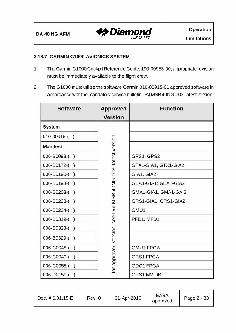
2.16.7 GARMIN G1000 AVIONICS SYSTEM
1. The Garmin G1000 Cockpit Reference Guide, 190-00953-00, appropriate revisionmust be immediately available to the flight crew.
2. The G1000 must utilize the software Garmin 010-00915-01 approved software inaccordance with the mandatory service bulletin DAI MSB 40NG-003, latest version.
Software ApprovedVersion
Function
System
010-00915-( )
Manifest
006-B0093-( ) GPS1, GPS2
006-B0172-( ) GTX1-GIA1, GTX1-GIA2
006-B0190-( ) GIA1, GIA2
006-B0193-( ) GEA1-GIA1; GEA1-GIA2
006-B0203-( ) GMA1-GIA1, GMA1-GAI2
006-B0223-( ) GRS1-GIA1, GRS1-GIA2
006-B0224-( ) GMU1
006-B0319-( ) PFD1, MFD1
006-B0328-( )
006-B0329-( )
006-C0048-( ) GMU1 FPGA
006-C0049-( ) GRS1 FPGA
006-C0055-( ) GDC1 FPGA
006-D0159-( ) GRS1 MV DB for a
ppro
ved
vers
ion,
see
DA
I MS
B 4
0NG
-003
, lat
est v
ersi
on
Operation
LimitationsDA 40 NG AFM
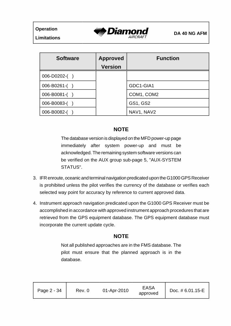
Software ApprovedVersion
Function
Page 2 - 34 Rev. 0 01-Apr-2010 EASAapproved Doc. # 6.01.15-E
006-D0202-( )
006-B0261-( ) GDC1-GIA1
006-B0081-( ) COM1, COM2
006-B0083-( ) GS1, GS2
006-B0082-( ) NAV1, NAV2
NOTEThe database version is displayed on the MFD power-up pageimmediately after system power-up and must beacknowledged. The remaining system software versions canbe verified on the AUX group sub-page 5, "AUX-SYSTEMSTATUS".
3. IFR enroute, oceanic and terminal navigation predicated upon the G1000 GPS Receiveris prohibited unless the pilot verifies the currency of the database or verifies eachselected way point for accuracy by reference to current approved data.
4. Instrument approach navigation predicated upon the G1000 GPS Receiver must beaccomplished in accordance with approved instrument approach procedures that areretrieved from the GPS equipment database. The GPS equipment database mustincorporate the current update cycle.
NOTENot all published approaches are in the FMS database. Thepilot must ensure that the planned approach is in thedatabase.
DA 40 NG AFMOperation
Limitations
Doc. # 6.01.15-E Rev. 0 01-Apr-2010 EASAapproved Page 2 - 35
(a) Instrument approaches utilizing the GPS receiver must be conducted in theapproach mode and Receiver Autonomous Integrity Monitoring (RAIM) mustbe available at the Final Approach Fix.
(b) Accomplishment of ILS, LOC, LOC-BC, LDA, SDF, MLS or any other type ofapproach not approved for GPS overlay with the G1000 GPS receiver is notauthorized.
(c) Use of the G1000 VOR/ILS receiver to fly approaches not approved for GPSrequire VOR/ILS navigation data to be present on the display.
(d) When an alternate airport is required by the applicable operating rules, it mustbe served by an approach based on other than GPS or Loran-C navigation,the airplane must have the operational equipment capable of using thatnavigation aid, and the required navigation aid must be operational.
(e) VNAV information may be utilized for advisory information only. Use of VNAVinformation for Instrument Approach Procedures does not guarantee step-downfix altitude protection, or arrival at approach minimums in normal position to land.
(f) RNAV (GPS) approaches must be conducted utilizing the GPS sensor.
(g) RNP RNAV operations are not authorized, except as noted in Chapter 1 of thisAFM.
5. If not previously defined, the following default settings must be made in the "SYSTEMSETUP" menu of the G1000 prior to operation (refer to Pilot's Guide for procedureif necessary):
(a) DIS, SPD : nm, kt (sets navigation units to "nautical miles" and "knots")
(b) ALT, VS : ft, fpm (sets altitude units to "feet" and "feet per minute")
(c) POSITION : deg-min (sets navigation grid units to decimal minutes)
Operation
LimitationsDA 40 NG AFM
Page 2 - 36 Rev. 0 01-Apr-2010 EASAapproved Doc. # 6.01.15-E
NOTENavigation Information is referenced to WGS-84 referencesystem, and should only be used where the AeronauticalInformation Publication (including electronic data andaeronautical charts) conforms to WGS-84 or equivalent.
6. When AHRS is required to meet the items listed in the minimum operational equipment(serviceable) table in Section 2.13 of this AFM, operation is prohibited in the followingareas:
(a) North of 72° N latitude at all longitudes.
(b) South of 70° S latitude at all longitudes.
(c) North of 65° N latitude between longitude 75° W and 120° W (Northern Canada).
(d) North of 70° N latitude between longitude 70° W and 128° W (Northern Canada).
(e) North of 70° N latitude between longitude 85° E and 114° E (Northern Russia).
(f) South of 55° S latitude between longitude 120° E and 165° E (Region southof Australia and New Zealand).
When day VFR operations are conducted in the above areas, the MFD must be ina non-heading up orientation.
7. The fuel quantity, fuel remaining, range and endurance functions on the Fuel Page(displayed when pushing the FUEL button as shown in Section 7.9) of the FMS aresupplemental information only and must be verified by the flight crew.
DA 40 NG AFMOperation
Limitations
Doc. # 6.01.15-E Rev. 0 01-Apr-2010 EASAapproved Page 2 - 37
8. The GPS is not approved for WAAS operations:
(a) The G1000 integrated avionics system is NOT approved for GPS WAASoperations including GPS WAAS approach procedures such as "LPV","LNAV/VNAV", and "LNAV +V".
(b) SBAS (WAAS & MSAS) functionality must be disabled on the G 1000 GPSStatus page (refer to the G1000 Pilot´s Guide for procedure).
9. The availability of SafeTaxi®, ChartView, or FliteCharts® in electronic form on the G1000is for information purposes only, it is still mandatory to carry another source of chartson-board the airplane.
Operation
LimitationsDA 40 NG AFM
Page 2 - 38 Rev. 0 01-Apr-2010 EASAapproved Doc. # 6.01.15-E
2.16.8 AUTOPILOT LIMITATIONS
1. It is the responsibility of the pilot in command to monitor the autopilot when it isengaged. The pilot should be prepared to immediately disconnect the autopilot andto take prompt corrective action in the event of unexpected or unusual autopilotbehavior.
2. The autopilot must be disconnected (using the DISC button) during take-off and landing.
3. Following an autopilot or electric trim malfunction, reengaging the autopilot or manualelectric trim, or resetting the AUTOPILOT circuit breaker is prohibited until the causeof the malfunction has been determined and corrected.
4. The Garmin G1000 Cockpit Reference Guide for the Diamond DA 40 NG approvedrevision must be immediately available to the flight crew.
5. ILS approaches using the GFC700 / flight director are limited to Category I approaches.
6. Autopilot maximum airspeed: 165 KIASAutopilot minimum airspeed: 70 KIAS
7. The autopilot must be disengaged:
- below 200 ft AGL during approach,- below 800 ft AGL for all other phases of flight.
8. Overriding the autopilot to change pitch or roll attitude is prohibited. (Disengage orpress CWS while maneuvering.)

DA 40 NG AFMOperation
Limitations
Doc. # 6.01.15-E Rev. 0 01-Apr-2010 EASAapproved Page 2 - 39
9. The GFC 700 components must utilize the following or later approved softwareversions:
Sub-System Software Version
GDU v9.03
GDC 74 v3.02
GEA 7X v2.07
GPS v3.03
GIA 6X v5.65
GIA Audio v2.03
GMAX347 v4.01
GMU44 v2.01
GRS 77 v2.11
GTX 33X v5.01
GDL 69 v3.20.00
GSA 8X v2.20
GFC 700 v2.00
The system software versions can be verified on the AUX group sub-page 5, "AUX -SYSTEM STATUS".
10. The GFC 700 AFCS pre-flight test must be successfully completed prior to useof the autopilot, flight director, or manual electric trim. Use of the autopilot or manualelectric trim system is prohibited if the preflight test is not satisfactorily completed.
11. A pilot with the seat belt fastened must occupy the left pilot's seat during alloperations.
Operation
LimitationsDA 40 NG AFM
Page 2 - 40 Rev. 0 01-Apr-2010 EASAapproved Doc. # 6.01.15-E
Intentionally left blank.
DA 40 NG AFMEmergency
Procedures
Doc. # 6.01.15-E Rev. 0 01-Apr-2010 Page 3 - 1
CHAPTER 3EMERGENCY PROCEDURES
Page
3.1 INTRODUCTION . . . . . . . . . . . . . . . . . . . . . . . . . . . . . . . . . . . . . . . 3-43.1.1 GENERAL . . . . . . . . . . . . . . . . . . . . . . . . . . . . . . . . . . . . . . . 3-43.1.2 CERTAIN AIRSPEEDS IN EMERGENCIES . . . . . . . . . . . . . 3-53.1.3 SELECTING EMERGENCY FREQUENCY . . . . . . . . . . . . . . 3-5
3.2 AIRPLANE RELATED G1000 WARNINGS . . . . . . . . . . . . . . . . . . . 3-63.2.1 WARNINGS / GENERAL . . . . . . . . . . . . . . . . . . . . . . . . . . . 3-63.2.2 ENG TEMP . . . . . . . . . . . . . . . . . . . . . . . . . . . . . . . . . . . . . . 3-63.2.3 OIL TEMP . . . . . . . . . . . . . . . . . . . . . . . . . . . . . . . . . . . . . . . 3-83.2.4 OIL PRES . . . . . . . . . . . . . . . . . . . . . . . . . . . . . . . . . . . . . . . 3-103.2.5 GBOX TEMP . . . . . . . . . . . . . . . . . . . . . . . . . . . . . . . . . . . . 3-113.2.6 L/R FUEL TEMP . . . . . . . . . . . . . . . . . . . . . . . . . . . . . . . . . . 3-123.2.7 FUEL PRESS . . . . . . . . . . . . . . . . . . . . . . . . . . . . . . . . . . . . 3-133.2.8 ALTN AMPS . . . . . . . . . . . . . . . . . . . . . . . . . . . . . . . . . . . . . 3-143.2.9 ALTN FAIL . . . . . . . . . . . . . . . . . . . . . . . . . . . . . . . . . . . . . . 3-153.2.10 STARTER . . . . . . . . . . . . . . . . . . . . . . . . . . . . . . . . . . . . . . 3-163.2.11 DOOR OPEN . . . . . . . . . . . . . . . . . . . . . . . . . . . . . . . . . . . 3-16
3.3 G1000 SYSTEM WARNINGS . . . . . . . . . . . . . . . . . . . . . . . . . . . . 3-173.3.1 RED X . . . . . . . . . . . . . . . . . . . . . . . . . . . . . . . . . . . . . . . . . 3-173.3.2 ATTITUDE FAIL . . . . . . . . . . . . . . . . . . . . . . . . . . . . . . . . . 3-173.3.3 AIRSPEED FAIL . . . . . . . . . . . . . . . . . . . . . . . . . . . . . . . . . 3-173.3.4 ALTITUDE FAIL . . . . . . . . . . . . . . . . . . . . . . . . . . . . . . . . . 3-173.3.5 VERT SPEED FAIL . . . . . . . . . . . . . . . . . . . . . . . . . . . . . . . 3-183.3.6 HDG . . . . . . . . . . . . . . . . . . . . . . . . . . . . . . . . . . . . . . . . . . 3-18
Emergency
ProceduresDA 40 NG AFM
Page 3 - 2 Rev. 0 01-Apr-2010 Doc. # 6.01.15-E
3.4 G1000 FAILURES . . . . . . . . . . . . . . . . . . . . . . . . . . . . . . . . . . . . . 3-193.4.1 NAVIGATION INFORMATION FAILURE . . . . . . . . . . . . . . 3-193.4.2 PFD OR MFD DISPLAY FAILURE . . . . . . . . . . . . . . . . . . . 3-193.4.3 AHRS FAILURE . . . . . . . . . . . . . . . . . . . . . . . . . . . . . . . . . 3-203.4.4 AIR DATA COMPUTER (ADC) FAILURE . . . . . . . . . . . . . . 3-213.4.5 ERRONEOUS OR LOSS OF ENGINE AND FUEL DISPLAYS
. . . . . . . . . . . . . . . . . . . . . . . . . . . . . . . . . . . . . . . . . . . . . . . 3-213.4.6 ERRONEOUS OR LOSS OF WARNING/CAUTION ANNUNCIATORS
. . . . . . . . . . . . . . . . . . . . . . . . . . . . . . . . . . . . . . . . . . . . . . . 3-223.5 ENGINE PROBLEMS . . . . . . . . . . . . . . . . . . . . . . . . . . . . . . . . . . 3-23
3.5.1 ENGINE PROBLEMS ON GROUND . . . . . . . . . . . . . . . . . 3-233.5.2 ENGINE PROBLEMS DURING TAKE-OFF . . . . . . . . . . . . 3-243.5.3 ENGINE TROUBLESHOOTING IN FLIGHT . . . . . . . . . . . . 3-263.5.4 ENGINE FAILURE IN FLIGHT . . . . . . . . . . . . . . . . . . . . . . 3-283.5.5 RESTARTING THE ENGINE IN FLIGHT . . . . . . . . . . . . . . 3-293.5.6 DEFECTIVE RPM REGULATING SYSTEM . . . . . . . . . . . . 3-313.5.7 FUEL TRANSFER PUMP FAILURE . . . . . . . . . . . . . . . . . . 3-35
3.6 FAILURES IN THE ELECTRICAL SYSTEM . . . . . . . . . . . . . . . . . 3-373.6.1 COMPLETE FAILURE OF THE ELECTRICAL SYSTEM . . 3-373.6.2 HIGH CURRENT . . . . . . . . . . . . . . . . . . . . . . . . . . . . . . . . . 3-383.6.3 STARTER MALFUNCTION . . . . . . . . . . . . . . . . . . . . . . . . . 3-38
3.7 SMOKE AND FIRE . . . . . . . . . . . . . . . . . . . . . . . . . . . . . . . . . . . . 3-393.7.1 SMOKE AND FIRE ON GROUND . . . . . . . . . . . . . . . . . . . 3-393.7.2 SMOKE AND FIRE DURING TAKE-OFF . . . . . . . . . . . . . . 3-413.7.3 SMOKE AND FIRE IN FLIGHT . . . . . . . . . . . . . . . . . . . . . . 3-44
3.8 GLIDING . . . . . . . . . . . . . . . . . . . . . . . . . . . . . . . . . . . . . . . . . . . . 3-463.9 EMERGENCY LANDINGS . . . . . . . . . . . . . . . . . . . . . . . . . . . . . . 3-47
3.9.1 EMERGENCY LANDING WITH ENGINE OFF . . . . . . . . . . 3-473.9.2 LANDING WITH A DEFECTIVE TIRE ON THE MAIN LANDING
GEAR . . . . . . . . . . . . . . . . . . . . . . . . . . . . . . . . . . . . . . . . . . 3-493.9.3 LANDING WITH DEFECTIVE BRAKES . . . . . . . . . . . . . . . 3-50
DA 40 NG AFMEmergency
Procedures
Doc. # 6.01.15-E Rev. 0 01-Apr-2010 Page 3 - 3
3.10 RECOVERY FROM AN UNINTENTIONAL SPIN . . . . . . . . . . . . . 3-513.11 OTHER EMERGENCIES . . . . . . . . . . . . . . . . . . . . . . . . . . . . . . . 3-52
3.11.1 ICING . . . . . . . . . . . . . . . . . . . . . . . . . . . . . . . . . . . . . . . . 3-523.11.2 SUSPICION OF CARBON MONOXIDE CONTAMINATION IN THE
CABIN . . . . . . . . . . . . . . . . . . . . . . . . . . . . . . . . . . . . . . . . . 3-533.11.3 UNLOCKED DOORS . . . . . . . . . . . . . . . . . . . . . . . . . . . . 3-543.11.4 AUTOPILOT OR ELECTRIC TRIM MALFUNCTION / FAILURE
. . . . . . . . . . . . . . . . . . . . . . . . . . . . . . . . . . . . . . . . . . . . . . . 3-55
NOTEProcedures for uncritical system faults are given in Chapter4B - ABNORMAL OPERATING PROCEDURES.
Emergency
ProceduresDA 40 NG AFM
Page 3 - 4 Rev. 0 01-Apr-2010 Doc. # 6.01.15-E
3.1 INTRODUCTION
3.1.1 GENERAL
This Chapter contains checklists as well as the description of recommended proceduresto be followed in the event of an emergency. Engine failure or other airplane-relatedemergencies are most unlikely to occur if the prescribed procedures for pre-flight checksand airplane maintenance are followed.
If, nonetheless, an emergency does arise, the guidelines given here should be followedand applied in order to clear the problem.
As it is impossible to foresee all kinds of emergencies and cover them in this AirplaneFlight Manual, a thorough understanding of the airplane by the pilot is, in addition to hisknowledge and experience, an essential factor in the solution of any problems which mayarise.
WARNINGIn each emergency, control over the flight attitude and thepreparation of a possible emergency landing have priorityover attempts to solve the current problem ("first fly theaircraft"). Prior to the flight the pilot must consider thesuitability of the terrain for an emergency landing for eachphase of the flight. For a safe flight the pilot must constantlykeep a safe minimum flight altitude. Solutions for variousadverse scenarios should be thought over in advance. Thusit should be guaranteed that the pilot is at no time shockedby an engine failure and that he can act calmly and withdetermination.
DA 40 NG AFMEmergency
Procedures
Doc. # 6.01.15-E Rev. 0 01-Apr-2010 Page 3 - 5
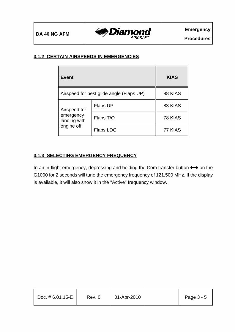
3.1.2 CERTAIN AIRSPEEDS IN EMERGENCIES
Event KIAS
Airspeed for best glide angle (Flaps UP) 88 KIAS
Airspeed foremergencylanding withengine off
Flaps UP 83 KIAS
Flaps T/O 78 KIAS
Flaps LDG 77 KIAS
3.1.3 SELECTING EMERGENCY FREQUENCY
In an in-flight emergency, depressing and holding the Com transfer button ȼ on theG1000 for 2 seconds will tune the emergency frequency of 121.500 MHz. If the displayis available, it will also show it in the "Active" frequency window.
Emergency
ProceduresDA 40 NG AFM
Page 3 - 6 Rev. 0 01-Apr-2010 Doc. # 6.01.15-E
3.2 AIRPLANE RELATED G1000 WARNINGS
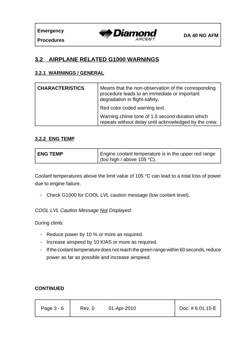
3.2.1 WARNINGS / GENERAL
CHARACTERISTICS Means that the non-observation of the correspondingprocedure leads to an immediate or importantdegradation in flight-safety.
Red color coded warning text.
Warning chime tone of 1.5 second duration whichrepeats without delay until acknowledged by the crew.
3.2.2 ENG TEMP
ENG TEMP Engine coolant temperature is in the upper red range(too high / above 105 °C).
Coolant temperatures above the limit value of 105 °C can lead to a total loss of powerdue to engine failure.
- Check G1000 for COOL LVL caution message (low coolant level).
COOL LVL Caution Message Not Displayed:
During climb:
- Reduce power by 10 % or more as required.- Increase airspeed by 10 KIAS or more as required.- If the coolant temperature does not reach the green range within 60 seconds, reduce
power as far as possible and increase airspeed.
CONTINUED

DA 40 NG AFMEmergency
Procedures
Doc. # 6.01.15-E Rev. 0 01-Apr-2010 Page 3 - 7
During cruise:
- Reduce power, or- Increase airspeed, if necessary by initiating a descent.- Check coolant temperature in green range.
CAUTIONIf high coolant temperature is indicated and the COOL LVLcaution message is not displayed, it can be assumed thatthere is no technical defect in the cooling system and that theabove mentioned procedure can decrease the temperature(s).This might not be the case if the coolant temperature doesnot return to the green range. In this case perform aprecautionary landing on the nearest suitable airfield. Preparefor an engine failure in accordance with 3.5.4 - ENGINEFAILURE IN FLIGHT.
COOL LVL Caution Message Displayed:
- Reduce power.- Expect loss of coolant.
WARNINGA further increase in coolant temperature must be expected.Prepare for an engine failure in accordance with3.5.4 - ENGINE FAILURE IN FLIGHT.
END OF CHECKLIST

Emergency
ProceduresDA 40 NG AFM
Page 3 - 8 Rev. 0 01-Apr-2010 Doc. # 6.01.15-E
3.2.3 OIL TEMP
OIL TEMP Engine oil temperature is in the upper red range (toohigh / above 140 °C).
Oil temperatures above the limit value of 140 °C can lead to a total loss of power dueto engine failure.
- Check oil pressure.
If the Oil Pressure Is Outside of the Green Range (Lower Limit):
- Reduce power.- Expect loss of engine oil.
WARNINGA further increase in oil temperature must be expected.Prepare for an engine failure in accordance with 3.5.4 -ENGINE FAILURE IN FLIGHT.
If the Oil Pressure Is Within the Green Range:
- Reduce power.- Increase airspeed.
CONTINUED
DA 40 NG AFMEmergency
Procedures
Doc. # 6.01.15-E Rev. 0 01-Apr-2010 Page 3 - 9
CAUTIONIf high oil temperature is announced and the oil pressureindication is within the green range, it can be assumed thatthere is no technical defect in the engine oil system and thatthe above mentioned procedure can decrease thetemperature(s). This might not be the case if the oiltemperature does not return to the green range. In this caseperform a precautionary landing on the nearest suitableairfield. Prepare for an engine failure in accordance with 3.5.4 - ENGINE FAILURE IN FLIGHT.
END OF CHECKLIST
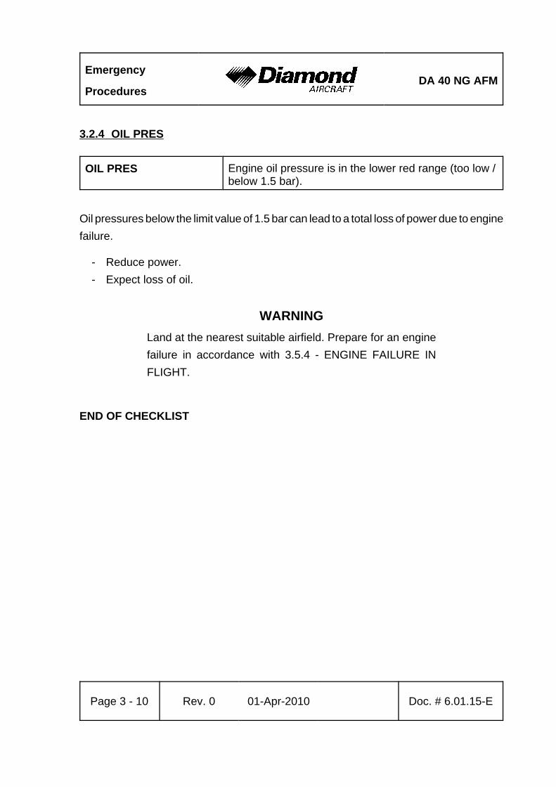
Emergency
ProceduresDA 40 NG AFM
Page 3 - 10 Rev. 0 01-Apr-2010 Doc. # 6.01.15-E
3.2.4 OIL PRES
OIL PRES Engine oil pressure is in the lower red range (too low /below 1.5 bar).
Oil pressures below the limit value of 1.5 bar can lead to a total loss of power due to enginefailure.
- Reduce power.- Expect loss of oil.
WARNINGLand at the nearest suitable airfield. Prepare for an enginefailure in accordance with 3.5.4 - ENGINE FAILURE INFLIGHT.
END OF CHECKLIST
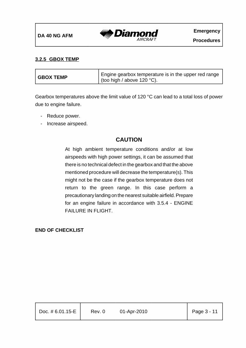
DA 40 NG AFMEmergency
Procedures
Doc. # 6.01.15-E Rev. 0 01-Apr-2010 Page 3 - 11
3.2.5 GBOX TEMP
GBOX TEMP Engine gearbox temperature is in the upper red range(too high / above 120 °C).
Gearbox temperatures above the limit value of 120 °C can lead to a total loss of powerdue to engine failure.
- Reduce power.- Increase airspeed.
CAUTIONAt high ambient temperature conditions and/or at lowairspeeds with high power settings, it can be assumed thatthere is no technical defect in the gearbox and that the abovementioned procedure will decrease the temperature(s). Thismight not be the case if the gearbox temperature does notreturn to the green range. In this case perform aprecautionary landing on the nearest suitable airfield. Preparefor an engine failure in accordance with 3.5.4 - ENGINEFAILURE IN FLIGHT.
END OF CHECKLIST
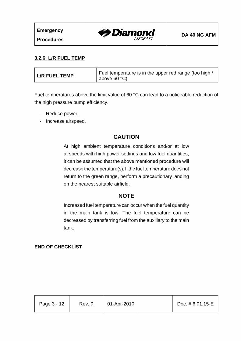
Emergency
ProceduresDA 40 NG AFM
Page 3 - 12 Rev. 0 01-Apr-2010 Doc. # 6.01.15-E
3.2.6 L/R FUEL TEMP
L/R FUEL TEMP Fuel temperature is in the upper red range (too high /above 60 °C).
Fuel temperatures above the limit value of 60 °C can lead to a noticeable reduction ofthe high pressure pump efficiency.
- Reduce power.- Increase airspeed.
CAUTIONAt high ambient temperature conditions and/or at lowairspeeds with high power settings and low fuel quantities,it can be assumed that the above mentioned procedure willdecrease the temperature(s). If the fuel temperature does notreturn to the green range, perform a precautionary landingon the nearest suitable airfield.
NOTEIncreased fuel temperature can occur when the fuel quantityin the main tank is low. The fuel temperature can bedecreased by transferring fuel from the auxiliary to the maintank.
END OF CHECKLIST
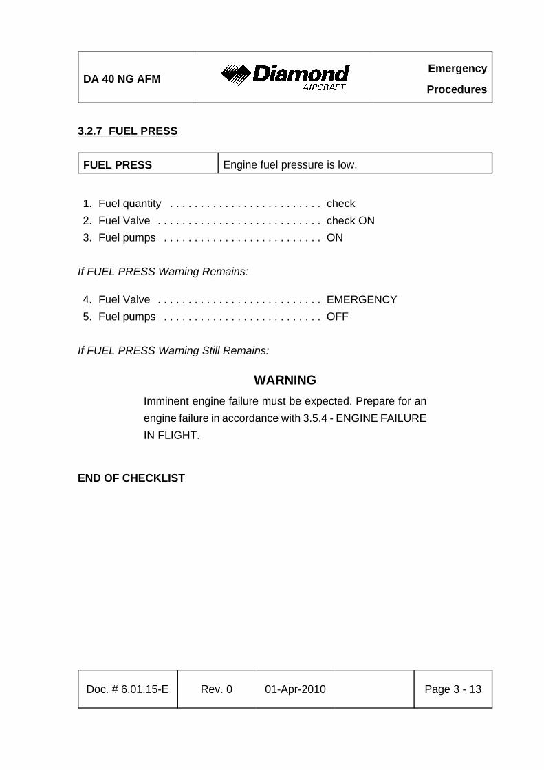
DA 40 NG AFMEmergency
Procedures
Doc. # 6.01.15-E Rev. 0 01-Apr-2010 Page 3 - 13
3.2.7 FUEL PRESS
FUEL PRESS Engine fuel pressure is low.
1. Fuel quantity . . . . . . . . . . . . . . . . . . . . . . . . . check2. Fuel Valve . . . . . . . . . . . . . . . . . . . . . . . . . . . check ON3. Fuel pumps . . . . . . . . . . . . . . . . . . . . . . . . . . ON
If FUEL PRESS Warning Remains:
4. Fuel Valve . . . . . . . . . . . . . . . . . . . . . . . . . . . EMERGENCY5. Fuel pumps . . . . . . . . . . . . . . . . . . . . . . . . . . OFF
If FUEL PRESS Warning Still Remains:
WARNINGImminent engine failure must be expected. Prepare for anengine failure in accordance with 3.5.4 - ENGINE FAILUREIN FLIGHT.
END OF CHECKLIST
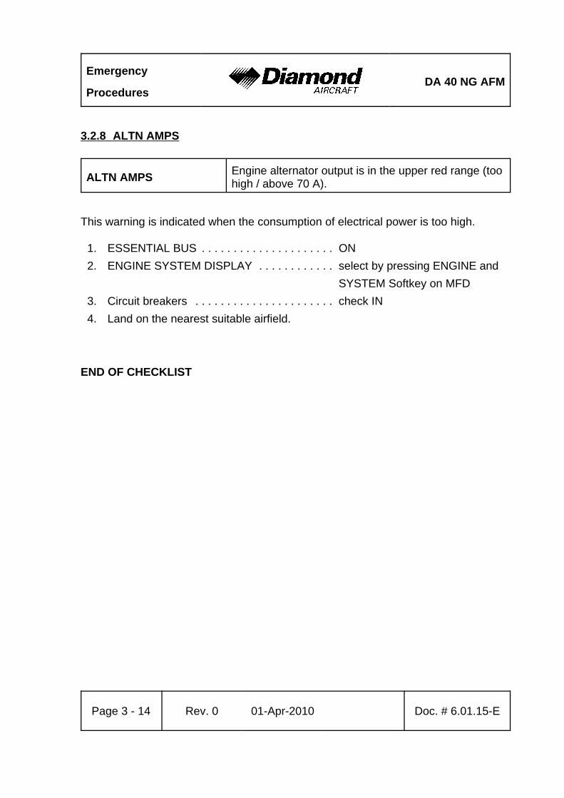
Emergency
ProceduresDA 40 NG AFM
Page 3 - 14 Rev. 0 01-Apr-2010 Doc. # 6.01.15-E
3.2.8 ALTN AMPS
ALTN AMPS Engine alternator output is in the upper red range (toohigh / above 70 A).
This warning is indicated when the consumption of electrical power is too high.
1. ESSENTIAL BUS . . . . . . . . . . . . . . . . . . . . . ON2. ENGINE SYSTEM DISPLAY . . . . . . . . . . . . select by pressing ENGINE and
SYSTEM Softkey on MFD3. Circuit breakers . . . . . . . . . . . . . . . . . . . . . . check IN4. Land on the nearest suitable airfield.
END OF CHECKLIST
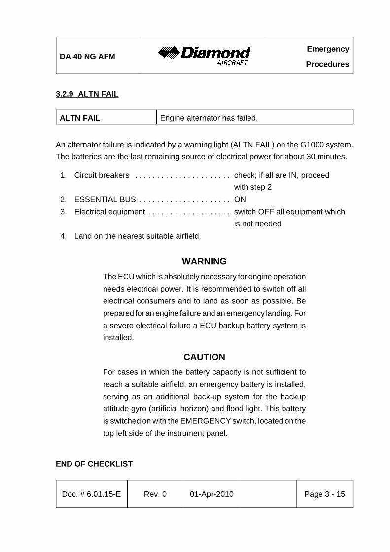
DA 40 NG AFMEmergency
Procedures
Doc. # 6.01.15-E Rev. 0 01-Apr-2010 Page 3 - 15
3.2.9 ALTN FAIL
ALTN FAIL Engine alternator has failed.
An alternator failure is indicated by a warning light (ALTN FAIL) on the G1000 system.The batteries are the last remaining source of electrical power for about 30 minutes.
1. Circuit breakers . . . . . . . . . . . . . . . . . . . . . . check; if all are IN, proceed with step 2
2. ESSENTIAL BUS . . . . . . . . . . . . . . . . . . . . . ON3. Electrical equipment . . . . . . . . . . . . . . . . . . . switch OFF all equipment which
is not needed4. Land on the nearest suitable airfield.
WARNINGThe ECU which is absolutely necessary for engine operationneeds electrical power. It is recommended to switch off allelectrical consumers and to land as soon as possible. Beprepared for an engine failure and an emergency landing. Fora severe electrical failure a ECU backup battery system isinstalled.
CAUTIONFor cases in which the battery capacity is not sufficient toreach a suitable airfield, an emergency battery is installed,serving as an additional back-up system for the backupattitude gyro (artificial horizon) and flood light. This batteryis switched on with the EMERGENCY switch, located on thetop left side of the instrument panel.
END OF CHECKLIST
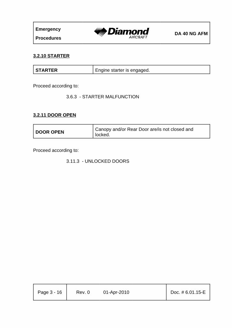
Emergency
ProceduresDA 40 NG AFM
Page 3 - 16 Rev. 0 01-Apr-2010 Doc. # 6.01.15-E
3.2.10 STARTER
STARTER Engine starter is engaged.
Proceed according to:
3.6.3 - STARTER MALFUNCTION
3.2.11 DOOR OPEN
DOOR OPEN Canopy and/or Rear Door are/is not closed andlocked.
Proceed according to:
3.11.3 - UNLOCKED DOORS
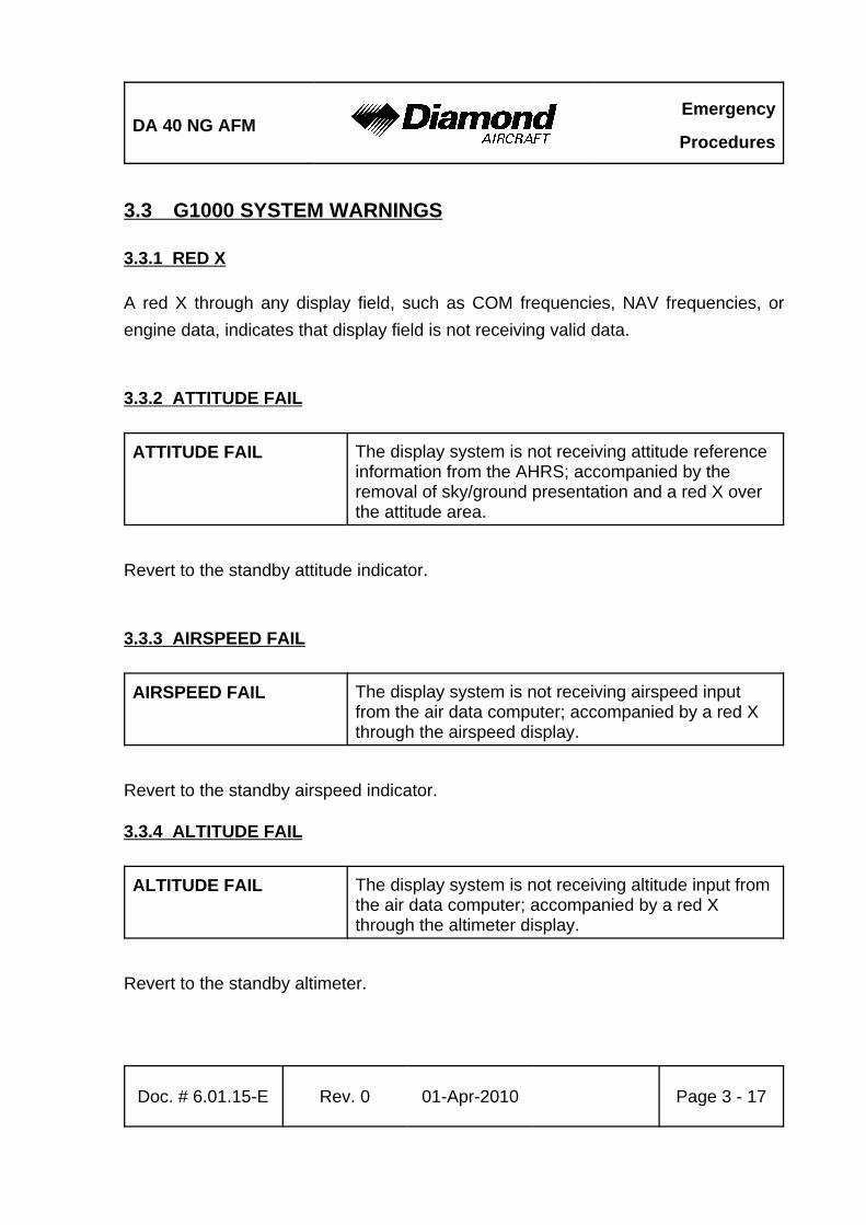
DA 40 NG AFMEmergency
Procedures
Doc. # 6.01.15-E Rev. 0 01-Apr-2010 Page 3 - 17
3.3 G1000 SYSTEM WARNINGS
3.3.1 RED X
A red X through any display field, such as COM frequencies, NAV frequencies, orengine data, indicates that display field is not receiving valid data.
3.3.2 ATTITUDE FAIL
ATTITUDE FAIL The display system is not receiving attitude referenceinformation from the AHRS; accompanied by theremoval of sky/ground presentation and a red X overthe attitude area.
Revert to the standby attitude indicator.
3.3.3 AIRSPEED FAIL
AIRSPEED FAIL The display system is not receiving airspeed inputfrom the air data computer; accompanied by a red Xthrough the airspeed display.
Revert to the standby airspeed indicator.
3.3.4 ALTITUDE FAIL
ALTITUDE FAIL The display system is not receiving altitude input fromthe air data computer; accompanied by a red Xthrough the altimeter display.
Revert to the standby altimeter.
Emergency
ProceduresDA 40 NG AFM
Page 3 - 18 Rev. 0 01-Apr-2010 Doc. # 6.01.15-E
3.3.5 VERT SPEED FAIL
VERT SPEED FAIL The display system is not receiving vertical speedinput from the air data computer; accompanied by ared X through the vertical speed display.
Determine vertical speed based on the change of altitude information.
3.3.6 HDG
HDG The display system is not receiving valid headinginput from the AHRS; accompanied by a red Xthrough the digital heading display.
Revert to the emergency compass.

DA 40 NG AFMEmergency
Procedures
Doc. # 6.01.15-E Rev. 0 01-Apr-2010 Page 3 - 19
3.4 G1000 FAILURES
3.4.1 NAVIGATION INFORMATION FAILURE
If Garmin G1000 GPS navigation information is not available or invalid, utilize remainingoperational navigation equipment as required.
3.4.2 PFD OR MFD DISPLAY FAILURE
1. DISPLAY BACKUP button on audio panel . . push
Automatic Entry of Display Revisionary Mode
If the PFD and MFD have automatically entered reversionary mode, use the followingprocedure.
(a) DISPLAY BACKUP button on audio panel ...... PUSH (button will be OUT)
NOTEAfter automatic entry of reversionary mode, the pilot mustpress the DISPLAY BACKUP button on the audio panel. Afterthe DISPLAY BACKUP button has been pushed, the systemwill remain in reversionary mode even if the problem causingthe automatic entry of reversionary mode is resolved. Amaximum of one attempt to return to normal mode isapproved using the following procedure.
CONTINUED
Emergency
ProceduresDA 40 NG AFM
Page 3 - 20 Rev. 0 01-Apr-2010 Doc. # 6.01.15-E
(b) DISPLAY BACKUP button on audio panel ...... PUSH (button will be IN)
- If the system returns to normal mode, leave the DISPLAY BACKUP button IN andcontinue.
- lf the system remains in reversionary mode, or abnormal display behavior suchas display flashing occurs, then return the DISPLAY BACKUP button to the OUTposition.
END OF CHECKLIST
3.4.3 AHRS FAILURE
NOTEA failure of the Attitude and Heading Reference System(AHRS) is indicated by a removal of the sky/groundpresentation and a red X and a yellow "AHRS FAILURE"shown on the PFD. The digital heading presentation will bereplaced with a yellow "HDG" and the compass rose digitswill be removed. The course pointer will indicate straight upand course may be set using the digital window.
1. Use standby attitude indicator, emergency compass and Navigation Map2. Course . . . . . . . . . . . . . . . . . . . . . . . . . . . . . set using digital window
END OF CHECKLIST
DA 40 NG AFMEmergency
Procedures
Doc. # 6.01.15-E Rev. 0 01-Apr-2010 Page 3 - 21
3.4.4 AIR DATA COMPUTER (ADC) FAILURE
NOTEComplete loss of the air data computer is indicated by a red Xand yellow text over the airspeed, altimeter, vertical speed,TAS and OAT displays. Some FMS functions, such as trueairspeed and wind calculations, will also be lost.
1. Use standby airspeed indicator and altimeter.
END OF CHECKLIST
3.4.5 ERRONEOUS OR LOSS OF ENGINE AND FUEL DISPLAYS
NOTELoss of an engine parameter is indicated by a red X throughthe data field. Erroneous information may be identified byindications which do not agree with other system information.Erroneous indications may be determined by comparing adisplay with other displays and other system information.
1. Set power based on throttle lever position, engine noise and speed.2. Monitor other indications to determine the health of the engine.3. Use known power settings and performance data, refer to 5.3.2 - FUEL FLOW
DIAGRAM for approximate fuel flow values.4. Use other system information, such as annunciator messages, GPS, fuel quantity
and flow, to safely complete the flight.
END OF CHECKLIST
Emergency
ProceduresDA 40 NG AFM
Page 3 - 22 Rev. 0 01-Apr-2010 Doc. # 6.01.15-E
3.4.6 ERRONEOUS OR LOSS OF WARNING/CAUTION ANNUNCIATORS
NOTELoss of an annunciator may be indicated when engine or fueldisplays show an abnormal or emergency situation and theannunciator is not present. An erroneous annunciator maybe identified when an annunciator appears which does notagree with other displays or system information.
1. If an annunciator appears, treat it as if the condition exists. Refer toChapter 3 - EMERGENCY PROCEDURES or Chapter 4B - ABNORMALOPERATING PROCEDURES.
2. If a display indicates an abnormal condition but no annunciator is present, use othersystem information, such as engine displays, GPS fuel quantity and flow, todetermine if the condition exists. If it cannot be determined that the condition doesnot exist, treat the situation as if the condition exists. Refer toChapter 3 - EMERGENCY PROCEDURES or Chapter 4B - ABNORMALOPERATING PROCEDURES.
END OF CHECKLIST
DA 40 NG AFMEmergency
Procedures
Doc. # 6.01.15-E Rev. 0 01-Apr-2010 Page 3 - 23
3.5 ENGINE PROBLEMS
3.5.1 ENGINE PROBLEMS ON GROUND
1. Power lever . . . . . . . . . . . . . . . . . . . . . . . . . IDLE2. Brakes . . . . . . . . . . . . . . . . . . . . . . . . . . . . . as required
NOTEIf considered necessary, the engine must be shut down.Otherwise the cause of the problem must be established inorder to re-establish engine performance.
CAUTIONIf the oil pressure is in the red range, the engine must be shutdown immediately.
WARNINGIf the problem cannot be cleared, the airplane must not beflown.
END OF CHECKLIST
Emergency
ProceduresDA 40 NG AFM
Page 3 - 24 Rev. 0 01-Apr-2010 Doc. # 6.01.15-E
3.5.2 ENGINE PROBLEMS DURING TAKE-OFF
(a) Take-Off Can Still Be Aborted (Sufficient Runway Length Available)
Land Straight Ahead:
1. Power lever . . . . . . . . . . . . . . . . . . . . . . . . . IDLE
On the Ground:
2. Brakes . . . . . . . . . . . . . . . . . . . . . . . . . . . . . as required
WARNINGIf sufficient time is remaining, the risk of fire in the event ofa collision can be reduced as follows:
- Fuel valve . . . . . . . . . . . . . . . . . . OFF- ENGINE MASTER . . . . . . . . . . . OFF- ELECTRIC MASTER . . . . . . . . . . OFF
END OF CHECKLIST
DA 40 NG AFMEmergency
Procedures
Doc. # 6.01.15-E Rev. 0 01-Apr-2010 Page 3 - 25
(b) Take-Off Can No Longer Be Aborted
1. Airspeed . . . . . . . . . . . . . . . . . . . . . . . . . . . . immediate pitch down to avoidairspeed reduction
WARNINGIf, in the event of an engine problem occurring during take-off,the take-off can no longer be aborted and a safe height hasnot been reached, then a straight-ahead emergency landingshould be considered. Do not attempt to turn back to theairfield. Turning back can be fatal.
If Time Allows:
2. Power lever . . . . . . . . . . . . . . . . . . . . . . . . . check MAX3. Fuel pumps . . . . . . . . . . . . . . . . . . . . . . . . . check ON5. VOTER switch . . . . . . . . . . . . . . . . . . . . . . . check AUTO
WARNINGIf the problem does not clear itself immediately, and theengine is no longer producing sufficient power, then anemergency landing must be carried out in accordance with3.9.1 - EMERGENCY LANDING WITH ENGINE OFF.
END OF CHECKLIST
Emergency
ProceduresDA 40 NG AFM
Page 3 - 26 Rev. 0 01-Apr-2010 Doc. # 6.01.15-E
3.5.3 ENGINE TROUBLESHOOTING IN FLIGHT
WARNINGControl over the flight attitude has priority over attempts tosolve the current problem ("first fly the airplane").
1. Airspeed . . . . . . . . . . . . . . . . . . . . . . . . . . . . 88 KIAS2. Power lever . . . . . . . . . . . . . . . . . . . . . . . . . MAX
NOTEIf the loss of power was due to unintentional setting of thePOWER lever, you may adjust the friction lock and continueyour flight.
Depending on the situation the following attempts can be made to restore normal engineoperation:
3. Circuit breakers . . . . . . . . . . . . . . . . . . . . . . check / reset if necessary
If normal engine operation is restored continue flight and land as soon as possible.
Otherwise:
4. VOTER switch . . . . . . . . . . . . . . . . . . . . . . . swap between ECU A and B
If either ECU A or B setting restores normal engine operation then maintain ECU settingand land as soon as possible.
CONTINUED
DA 40 NG AFMEmergency
Procedures
Doc. # 6.01.15-E Rev. 0 01-Apr-2010 Page 3 - 27
Otherwise:
5. VOTER switch . . . . . . . . . . . . . . . . . . . . . . . switch back to AUTO to retain ECU redundancy
If normal engine operation is restored continue flight and land as soon as possible.
Otherwise:
6. Fuel valve . . . . . . . . . . . . . . . . . . . . . . . . . . . EMERGENCY
If normal engine operation is restored continue flight and land as soon as possible. Remainwithin maximum allowable lateral imbalance.
Otherwise:
7. Fuel valve . . . . . . . . . . . . . . . . . . . . . . . . . . . NORMAL8. Alternate air . . . . . . . . . . . . . . . . . . . . . . . . . OPEN9. Power lever . . . . . . . . . . . . . . . . . . . . . . . . . apply power as required
If normal engine operation is restored continue flight and land as soon as practicable.
If normal engine operation could not be restored by following the procedures in this sectionprepare for 3.5.4 - ENGINE FAILURE IN FLIGHT and land as soon as possible.
END OF CHECKLIST
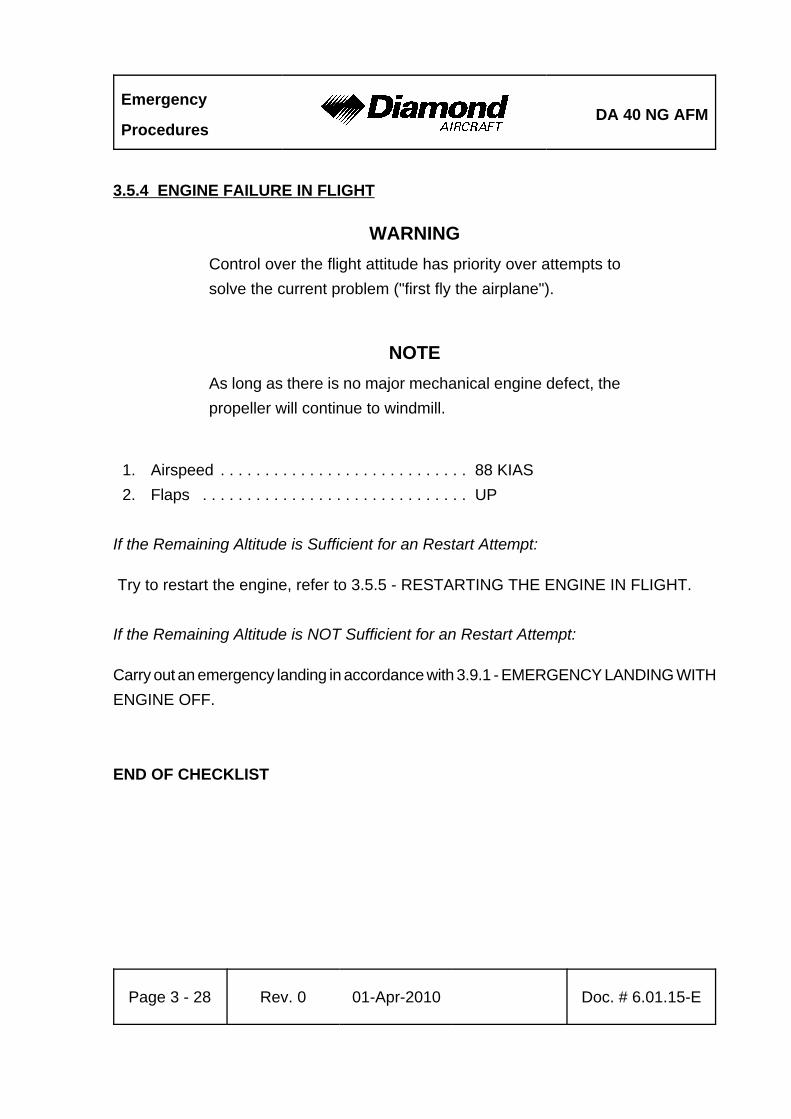
Emergency
ProceduresDA 40 NG AFM
Page 3 - 28 Rev. 0 01-Apr-2010 Doc. # 6.01.15-E
3.5.4 ENGINE FAILURE IN FLIGHT
WARNINGControl over the flight attitude has priority over attempts tosolve the current problem ("first fly the airplane").
NOTEAs long as there is no major mechanical engine defect, thepropeller will continue to windmill.
1. Airspeed . . . . . . . . . . . . . . . . . . . . . . . . . . . . 88 KIAS2. Flaps . . . . . . . . . . . . . . . . . . . . . . . . . . . . . . UP
If the Remaining Altitude is Sufficient for an Restart Attempt:
Try to restart the engine, refer to 3.5.5 - RESTARTING THE ENGINE IN FLIGHT.
If the Remaining Altitude is NOT Sufficient for an Restart Attempt:
Carry out an emergency landing in accordance with 3.9.1 - EMERGENCY LANDING WITHENGINE OFF.
END OF CHECKLIST
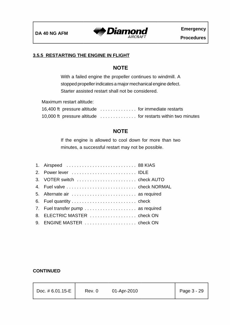
DA 40 NG AFMEmergency
Procedures
Doc. # 6.01.15-E Rev. 0 01-Apr-2010 Page 3 - 29
3.5.5 RESTARTING THE ENGINE IN FLIGHT
NOTEWith a failed engine the propeller continues to windmill. Astopped propeller indicates a major mechanical engine defect.Starter assisted restart shall not be considered.
Maximum restart altitude:16,400 ft pressure altitude . . . . . . . . . . . . . . for immediate restarts10,000 ft pressure altitude . . . . . . . . . . . . . . for restarts within two minutes
NOTEIf the engine is allowed to cool down for more than twominutes, a successful restart may not be possible.
1. Airspeed . . . . . . . . . . . . . . . . . . . . . . . . . . . 88 KIAS2. Power lever . . . . . . . . . . . . . . . . . . . . . . . . . IDLE3. VOTER switch . . . . . . . . . . . . . . . . . . . . . . . check AUTO4. Fuel valve . . . . . . . . . . . . . . . . . . . . . . . . . . . check NORMAL5. Alternate air . . . . . . . . . . . . . . . . . . . . . . . . . as required6. Fuel quantity . . . . . . . . . . . . . . . . . . . . . . . . . check7. Fuel transfer pump . . . . . . . . . . . . . . . . . . . . as required8. ELECTRIC MASTER . . . . . . . . . . . . . . . . . . check ON9. ENGINE MASTER . . . . . . . . . . . . . . . . . . . . check ON
CONTINUED
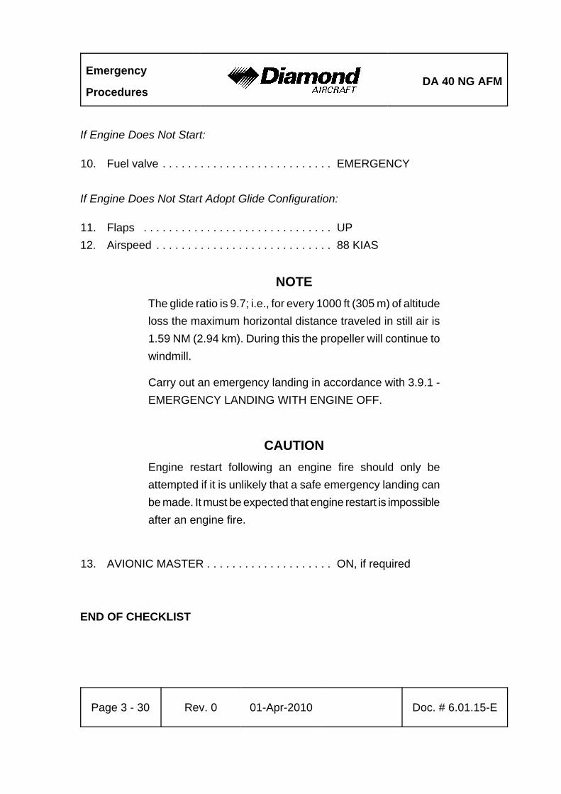
Emergency
ProceduresDA 40 NG AFM
Page 3 - 30 Rev. 0 01-Apr-2010 Doc. # 6.01.15-E
If Engine Does Not Start:
10. Fuel valve . . . . . . . . . . . . . . . . . . . . . . . . . . . EMERGENCY
If Engine Does Not Start Adopt Glide Configuration:
11. Flaps . . . . . . . . . . . . . . . . . . . . . . . . . . . . . . UP12. Airspeed . . . . . . . . . . . . . . . . . . . . . . . . . . . . 88 KIAS
NOTEThe glide ratio is 9.7; i.e., for every 1000 ft (305 m) of altitudeloss the maximum horizontal distance traveled in still air is1.59 NM (2.94 km). During this the propeller will continue towindmill.
Carry out an emergency landing in accordance with 3.9.1 -EMERGENCY LANDING WITH ENGINE OFF.
CAUTIONEngine restart following an engine fire should only beattempted if it is unlikely that a safe emergency landing canbe made. It must be expected that engine restart is impossibleafter an engine fire.
13. AVIONIC MASTER . . . . . . . . . . . . . . . . . . . . ON, if required
END OF CHECKLIST
DA 40 NG AFMEmergency
Procedures
Doc. # 6.01.15-E Rev. 0 01-Apr-2010 Page 3 - 31
3.5.6 DEFECTIVE RPM REGULATING SYSTEM
WARNINGIn case of defective RPM regulating system, reduced engineperformance should be anticipated.
CAUTIONFollowing a failure of the governor the RPM should beadjusted with the power lever.
CAUTIONThe power lever should be moved slowly, in order to avoidover-speeding and excessively rapid RPM changes. The lightwooden propeller blades produce more rapid RPM changesthan metal blades.
(a) Oscillating RPM
1. Power setting . . . . . . . . . . . . . . . . . . . . . . . . change
If the Problem Does Not Clear:
2. VOTER switch . . . . . . . . . . . . . . . . . . . . . . . swap between ECU A and B
If the Problem Does Not Clear:
3. VOTER switch . . . . . . . . . . . . . . . . . . . . . . . AUTO4. Land on the nearest suitable airfield.
END OF CHECKLIST
Emergency
ProceduresDA 40 NG AFM
Page 3 - 32 Rev. 0 01-Apr-2010 Doc. # 6.01.15-E
(b) Propeller Overspeed
CAUTIONClimb performance will be reduced.
NOTEThe propeller now works like a fixed pitch propeller. RPM iscontrolled by the engine power setting. Flight to the nearestairfield can be continued with a lower power setting and ata lower airspeed. Climb and go-around may not be possibleunder all conditions.
1. Power lever . . . . . . . . . . . . . . . . . . . . . . . . . reduce to not exceed 2300 RPM2. Airspeed . . . . . . . . . . . . . . . . . . . . . . . . . . . . 88 KIAS3. Flaps . . . . . . . . . . . . . . . . . . . . . . . . . . . . . . check UP
After RPM has Stabilized Below 2300 RPM:
4. Airspeed . . . . . . . . . . . . . . . . . . . . . . . . . . . . as required, do not exceed 2300 RPM5. Power Lever . . . . . . . . . . . . . . . . . . . . . . . . . as required, do not exceed 2300 RPM
If the Problem Does Not Clear:
6. VOTER switch . . . . . . . . . . . . . . . . . . . . . . . swap between ECU A and B
NOTEIf selecting ECU A or ECU B does not solve the problem,switch back to AUTOMATIC. Keep controlling the climb/sinkrate with the power lever and do not exceed 2300 RPM.
CONTINUED
DA 40 NG AFMEmergency
Procedures
Doc. # 6.01.15-E Rev. 0 01-Apr-2010 Page 3 - 33
If the Problem Does Not Clear:
7. Land on the nearest suitable airfield.
If an Increased Climb Rate is Required:
8. Flaps . . . . . . . . . . . . . . . . . . . . . . . . . . . . . . T/O position9. Airspeed . . . . . . . . . . . . . . . . . . . . . . . . . . . . 72 KIAS
10. Power lever . . . . . . . . . . . . . . . . . . . . . . . . . . as required, do not exceed 2300 RPM
END OF CHECKLIST
Emergency
ProceduresDA 40 NG AFM
Page 3 - 34 Rev. 0 01-Apr-2010 Doc. # 6.01.15-E
(c) Propeller Underspeed
1. Power lever . . . . . . . . . . . . . . . . . . . . . . . . . as required
If the Problem Does Not Clear
2. VOTER switch . . . . . . . . . . . . . . . . . . . . . . . swap between ECU A and B
If the Problem Does Not Clear:
3. VOTER switch . . . . . . . . . . . . . . . . . . . . . . . AUTO4. Power lever . . . . . . . . . . . . . . . . . . . . . . . . . as required
WARNINGDue to this problem the propeller RPM will drop. There maybe no climb performance and no go-around power available.
5. Land on the nearest suitable airfield.
END OF CHECKLIST
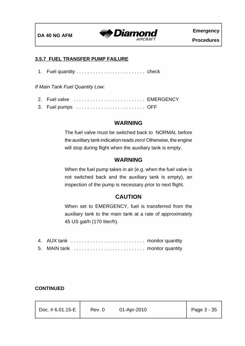
DA 40 NG AFMEmergency
Procedures
Doc. # 6.01.15-E Rev. 0 01-Apr-2010 Page 3 - 35
3.5.7 FUEL TRANSFER PUMP FAILURE
1. Fuel quantity . . . . . . . . . . . . . . . . . . . . . . . . . check
If Main Tank Fuel Quantity Low:
2. Fuel valve . . . . . . . . . . . . . . . . . . . . . . . . . . EMERGENCY 3. Fuel pumps . . . . . . . . . . . . . . . . . . . . . . . . . OFF
WARNINGThe fuel valve must be switched back to NORMAL beforethe auxiliary tank indication reads zero! Otherwise, the enginewill stop during flight when the auxiliary tank is empty.
WARNINGWhen the fuel pump takes in air (e.g. when the fuel valve isnot switched back and the auxiliary tank is empty), aninspection of the pump is necessary prior to next flight.
CAUTIONWhen set to EMERGENCY, fuel is transferred from theauxiliary tank to the main tank at a rate of approximately45 US gal/h (170 liter/h).
4. AUX tank . . . . . . . . . . . . . . . . . . . . . . . . . . . monitor quantity5. MAIN tank . . . . . . . . . . . . . . . . . . . . . . . . . . monitor quantity
CONTINUED
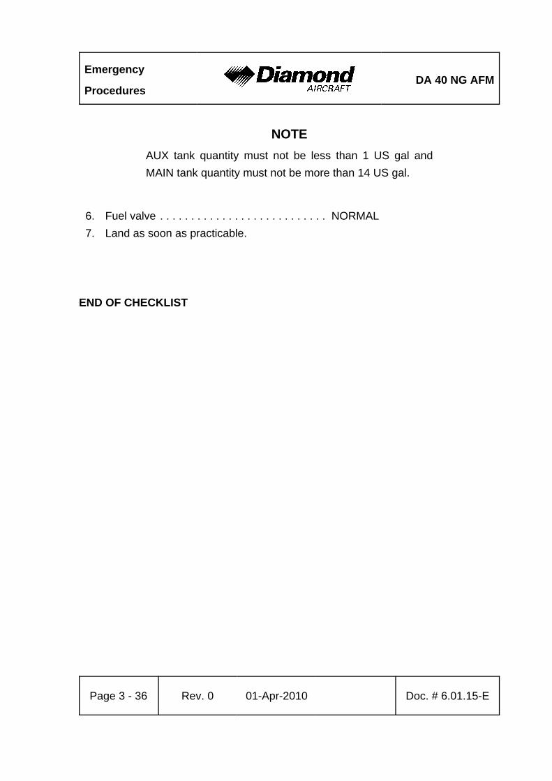
Emergency
ProceduresDA 40 NG AFM
Page 3 - 36 Rev. 0 01-Apr-2010 Doc. # 6.01.15-E
NOTEAUX tank quantity must not be less than 1 US gal andMAIN tank quantity must not be more than 14 US gal.
6. Fuel valve . . . . . . . . . . . . . . . . . . . . . . . . . . . NORMAL7. Land as soon as practicable.
END OF CHECKLIST
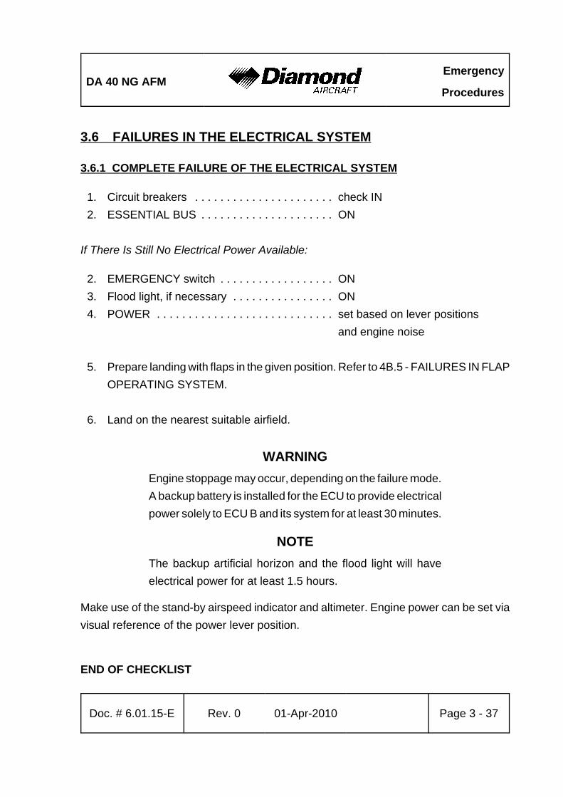
DA 40 NG AFMEmergency
Procedures
Doc. # 6.01.15-E Rev. 0 01-Apr-2010 Page 3 - 37
3.6 FAILURES IN THE ELECTRICAL SYSTEM
3.6.1 COMPLETE FAILURE OF THE ELECTRICAL SYSTEM
1. Circuit breakers . . . . . . . . . . . . . . . . . . . . . . check IN2. ESSENTIAL BUS . . . . . . . . . . . . . . . . . . . . . ON
If There Is Still No Electrical Power Available:
2. EMERGENCY switch . . . . . . . . . . . . . . . . . . ON3. Flood light, if necessary . . . . . . . . . . . . . . . . ON4. POWER . . . . . . . . . . . . . . . . . . . . . . . . . . . . set based on lever positions
and engine noise
5. Prepare landing with flaps in the given position. Refer to 4B.5 - FAILURES IN FLAPOPERATING SYSTEM.
6. Land on the nearest suitable airfield.
WARNINGEngine stoppage may occur, depending on the failure mode.A backup battery is installed for the ECU to provide electricalpower solely to ECU B and its system for at least 30 minutes.
NOTEThe backup artificial horizon and the flood light will haveelectrical power for at least 1.5 hours.
Make use of the stand-by airspeed indicator and altimeter. Engine power can be set viavisual reference of the power lever position.
END OF CHECKLIST
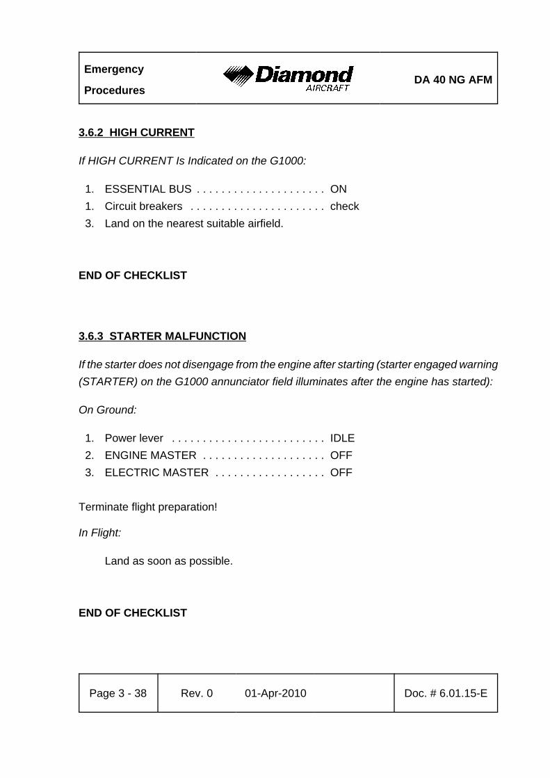
Emergency
ProceduresDA 40 NG AFM
Page 3 - 38 Rev. 0 01-Apr-2010 Doc. # 6.01.15-E
3.6.2 HIGH CURRENT
If HIGH CURRENT Is Indicated on the G1000:
1. ESSENTIAL BUS . . . . . . . . . . . . . . . . . . . . . ON1. Circuit breakers . . . . . . . . . . . . . . . . . . . . . . check3. Land on the nearest suitable airfield.
END OF CHECKLIST
3.6.3 STARTER MALFUNCTION
If the starter does not disengage from the engine after starting (starter engaged warning(STARTER) on the G1000 annunciator field illuminates after the engine has started):
On Ground:
1. Power lever . . . . . . . . . . . . . . . . . . . . . . . . . IDLE2. ENGINE MASTER . . . . . . . . . . . . . . . . . . . . OFF3. ELECTRIC MASTER . . . . . . . . . . . . . . . . . . OFF
Terminate flight preparation!
In Flight:
Land as soon as possible.
END OF CHECKLIST
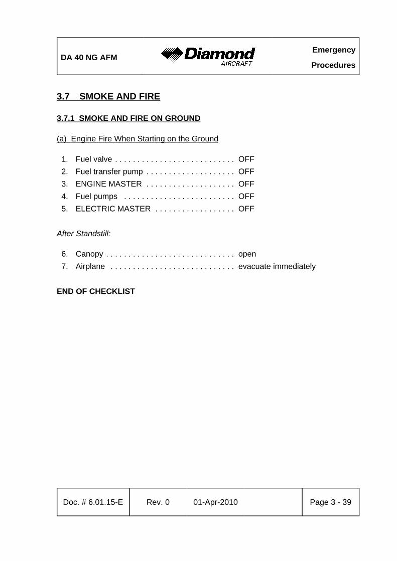
DA 40 NG AFMEmergency
Procedures
Doc. # 6.01.15-E Rev. 0 01-Apr-2010 Page 3 - 39
3.7 SMOKE AND FIRE
3.7.1 SMOKE AND FIRE ON GROUND
(a) Engine Fire When Starting on the Ground
1. Fuel valve . . . . . . . . . . . . . . . . . . . . . . . . . . . OFF2. Fuel transfer pump . . . . . . . . . . . . . . . . . . . . OFF3. ENGINE MASTER . . . . . . . . . . . . . . . . . . . . OFF4. Fuel pumps . . . . . . . . . . . . . . . . . . . . . . . . . OFF5. ELECTRIC MASTER . . . . . . . . . . . . . . . . . . OFF
After Standstill:
6. Canopy . . . . . . . . . . . . . . . . . . . . . . . . . . . . . open7. Airplane . . . . . . . . . . . . . . . . . . . . . . . . . . . . evacuate immediately
END OF CHECKLIST

Emergency
ProceduresDA 40 NG AFM
Page 3 - 40 Rev. 0 01-Apr-2010 Doc. # 6.01.15-E
(b) Electrical Fire with Smoke on the Ground
1. ELECTRIC MASTER . . . . . . . . . . . . . . . . . . OFF
If the Engine Is Running:
2. Power lever . . . . . . . . . . . . . . . . . . . . . . . . . IDLE3. ENGINE MASTER . . . . . . . . . . . . . . . . . . . . OFF4. Fuel pumps . . . . . . . . . . . . . . . . . . . . . . . . . OFF
When the Engine Has Stopped:
6. Canopy . . . . . . . . . . . . . . . . . . . . . . . . . . . . . open7. Airplane . . . . . . . . . . . . . . . . . . . . . . . . . . . . evacuate immediately
END OF CHECKLIST
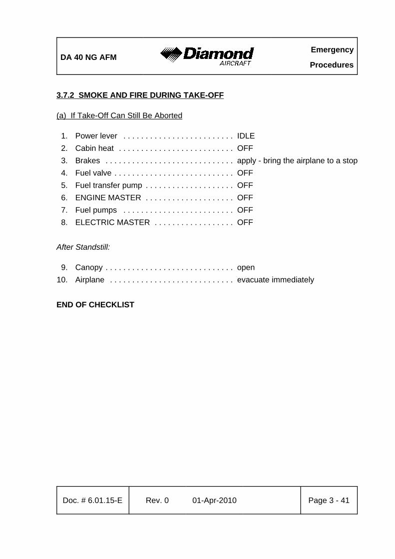
DA 40 NG AFMEmergency
Procedures
Doc. # 6.01.15-E Rev. 0 01-Apr-2010 Page 3 - 41
3.7.2 SMOKE AND FIRE DURING TAKE-OFF
(a) If Take-Off Can Still Be Aborted
1. Power lever . . . . . . . . . . . . . . . . . . . . . . . . . IDLE2. Cabin heat . . . . . . . . . . . . . . . . . . . . . . . . . . OFF3. Brakes . . . . . . . . . . . . . . . . . . . . . . . . . . . . . apply - bring the airplane to a stop4. Fuel valve . . . . . . . . . . . . . . . . . . . . . . . . . . . OFF5. Fuel transfer pump . . . . . . . . . . . . . . . . . . . . OFF6. ENGINE MASTER . . . . . . . . . . . . . . . . . . . . OFF7. Fuel pumps . . . . . . . . . . . . . . . . . . . . . . . . . OFF8. ELECTRIC MASTER . . . . . . . . . . . . . . . . . . OFF
After Standstill:
9. Canopy . . . . . . . . . . . . . . . . . . . . . . . . . . . . . open10. Airplane . . . . . . . . . . . . . . . . . . . . . . . . . . . . evacuate immediately
END OF CHECKLIST
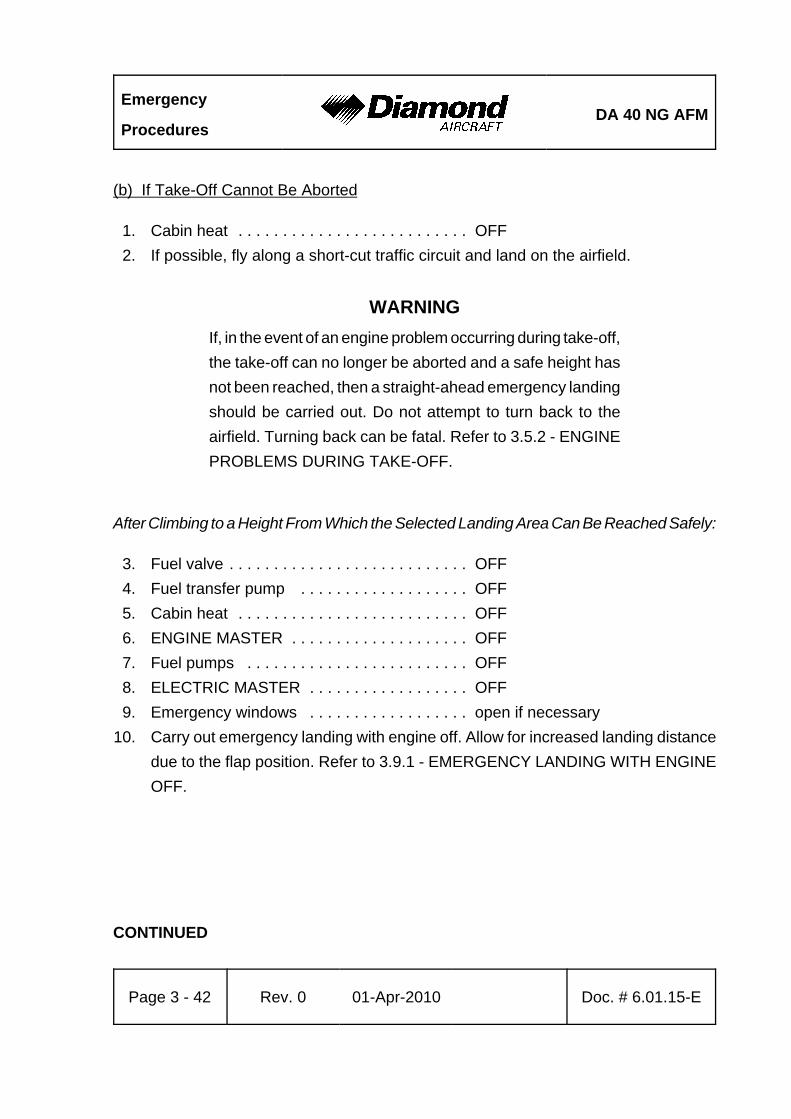
Emergency
ProceduresDA 40 NG AFM
Page 3 - 42 Rev. 0 01-Apr-2010 Doc. # 6.01.15-E
(b) If Take-Off Cannot Be Aborted
1. Cabin heat . . . . . . . . . . . . . . . . . . . . . . . . . . OFF2. If possible, fly along a short-cut traffic circuit and land on the airfield.
WARNINGIf, in the event of an engine problem occurring during take-off,the take-off can no longer be aborted and a safe height hasnot been reached, then a straight-ahead emergency landingshould be carried out. Do not attempt to turn back to theairfield. Turning back can be fatal. Refer to 3.5.2 - ENGINEPROBLEMS DURING TAKE-OFF.
After Climbing to a Height From Which the Selected Landing Area Can Be Reached Safely:
3. Fuel valve . . . . . . . . . . . . . . . . . . . . . . . . . . . OFF4. Fuel transfer pump . . . . . . . . . . . . . . . . . . . OFF5. Cabin heat . . . . . . . . . . . . . . . . . . . . . . . . . . OFF6. ENGINE MASTER . . . . . . . . . . . . . . . . . . . . OFF7. Fuel pumps . . . . . . . . . . . . . . . . . . . . . . . . . OFF8. ELECTRIC MASTER . . . . . . . . . . . . . . . . . . OFF9. Emergency windows . . . . . . . . . . . . . . . . . . open if necessary
10. Carry out emergency landing with engine off. Allow for increased landing distancedue to the flap position. Refer to 3.9.1 - EMERGENCY LANDING WITH ENGINEOFF.
CONTINUED
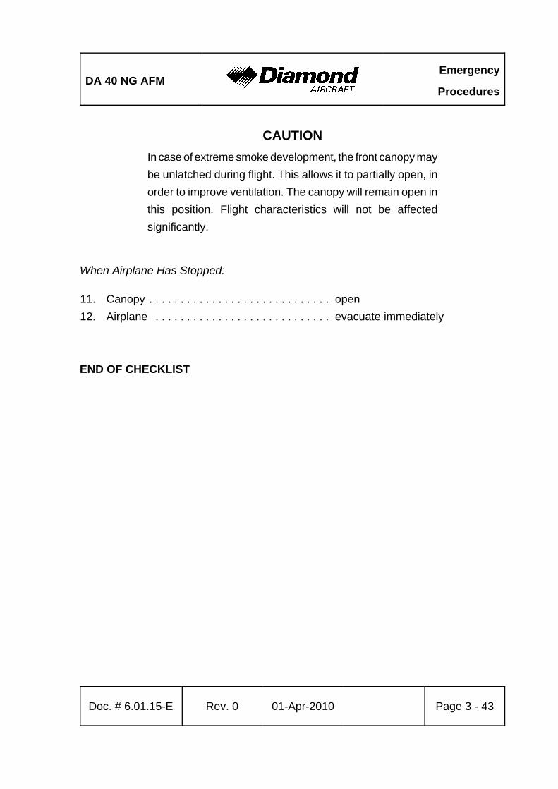
DA 40 NG AFMEmergency
Procedures
Doc. # 6.01.15-E Rev. 0 01-Apr-2010 Page 3 - 43
CAUTIONIn case of extreme smoke development, the front canopy maybe unlatched during flight. This allows it to partially open, inorder to improve ventilation. The canopy will remain open inthis position. Flight characteristics will not be affectedsignificantly.
When Airplane Has Stopped:
11. Canopy . . . . . . . . . . . . . . . . . . . . . . . . . . . . . open12. Airplane . . . . . . . . . . . . . . . . . . . . . . . . . . . . evacuate immediately
END OF CHECKLIST
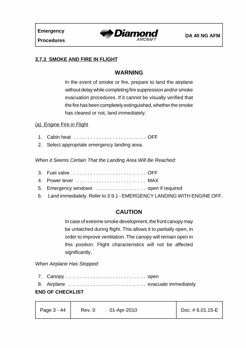
Emergency
ProceduresDA 40 NG AFM
Page 3 - 44 Rev. 0 01-Apr-2010 Doc. # 6.01.15-E
3.7.3 SMOKE AND FIRE IN FLIGHT
WARNINGIn the event of smoke or fire, prepare to land the airplanewithout delay while completing fire suppression and/or smokeevacuation procedures. If it cannot be visually verified thatthe fire has been completely extinguished, whether the smokehas cleared or not, land immediately.
(a) Engine Fire in Flight
1. Cabin heat . . . . . . . . . . . . . . . . . . . . . . . . . . OFF2. Select appropriate emergency landing area.
When it Seems Certain That the Landing Area Will Be Reached:
3. Fuel valve . . . . . . . . . . . . . . . . . . . . . . . . . . . OFF4. Power lever . . . . . . . . . . . . . . . . . . . . . . . . . MAX5. Emergency windows . . . . . . . . . . . . . . . . . . open if required6. Land immediately. Refer to 3.9.1 - EMERGENCY LANDING WITH ENGINE OFF.
CAUTIONIn case of extreme smoke development, the front canopy maybe unlatched during flight. This allows it to partially open, inorder to improve ventilation. The canopy will remain open inthis position. Flight characteristics will not be affectedsignificantly.
When Airplane Has Stopped:
7. Canopy . . . . . . . . . . . . . . . . . . . . . . . . . . . . . open8. Airplane . . . . . . . . . . . . . . . . . . . . . . . . . . . . evacuate immediately
END OF CHECKLIST
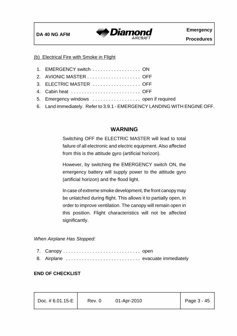
DA 40 NG AFMEmergency
Procedures
Doc. # 6.01.15-E Rev. 0 01-Apr-2010 Page 3 - 45
(b) Electrical Fire with Smoke in Flight
1. EMERGENCY switch . . . . . . . . . . . . . . . . . . ON2. AVIONIC MASTER . . . . . . . . . . . . . . . . . . . . OFF3. ELECTRIC MASTER . . . . . . . . . . . . . . . . . . OFF4. Cabin heat . . . . . . . . . . . . . . . . . . . . . . . . . . OFF5. Emergency windows . . . . . . . . . . . . . . . . . . open if required6. Land immediately. Refer to 3.9.1 - EMERGENCY LANDING WITH ENGINE OFF.
WARNINGSwitching OFF the ELECTRIC MASTER will lead to totalfailure of all electronic and electric equipment. Also affectedfrom this is the attitude gyro (artificial horizon).
However, by switching the EMERGENCY switch ON, theemergency battery will supply power to the attitude gyro(artificial horizon) and the flood light.
In case of extreme smoke development, the front canopy maybe unlatched during flight. This allows it to partially open, inorder to improve ventilation. The canopy will remain open inthis position. Flight characteristics will not be affectedsignificantly.
When Airplane Has Stopped:
7. Canopy . . . . . . . . . . . . . . . . . . . . . . . . . . . . . open8. Airplane . . . . . . . . . . . . . . . . . . . . . . . . . . . . evacuate immediately
END OF CHECKLIST
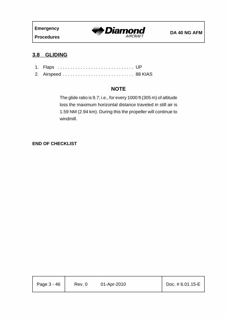
Emergency
ProceduresDA 40 NG AFM
Page 3 - 46 Rev. 0 01-Apr-2010 Doc. # 6.01.15-E
3.8 GLIDING
1. Flaps . . . . . . . . . . . . . . . . . . . . . . . . . . . . . . UP2. Airspeed . . . . . . . . . . . . . . . . . . . . . . . . . . . . 88 KIAS
NOTEThe glide ratio is 9.7; i.e., for every 1000 ft (305 m) of altitudeloss the maximum horizontal distance traveled in still air is1.59 NM (2.94 km). During this the propeller will continue towindmill.
END OF CHECKLIST

DA 40 NG AFMEmergency
Procedures
Doc. # 6.01.15-E Rev. 0 01-Apr-2010 Page 3 - 47
3.9 EMERGENCY LANDINGS
NOTEFor all airspeed tables in the following sections apply linearvariations between weights.
3.9.1 EMERGENCY LANDING WITH ENGINE OFF
1. ENGINE MASTER . . . . . . . . . . . . . . . . . . . . check OFF2. Fuel transfer pump . . . . . . . . . . . . . . . . . . . . OFF3. Fuel pumps . . . . . . . . . . . . . . . . . . . . . . . . . OFF4. Fuel valve . . . . . . . . . . . . . . . . . . . . . . . . . . . OFF5. AVIONIC MASTER . . . . . . . . . . . . . . . . . . . . OFF6. Safety harnesses . . . . . . . . . . . . . . . . . . . . . check fastened and tightened
When Sure of Making Landing Area:
7. FLAPS . . . . . . . . . . . . . . . . . . . . . . . . . . . . . T/O or LDG, as required
NOTEExtending the flaps to LDG will increase drag and incur a highsink rate. When the landing area can be reached safely,landing with flaps LDG is advisable.
CONTINUED
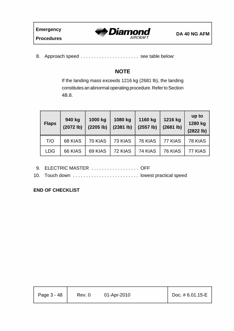
Emergency
ProceduresDA 40 NG AFM
Page 3 - 48 Rev. 0 01-Apr-2010 Doc. # 6.01.15-E
8. Approach speed . . . . . . . . . . . . . . . . . . . . . . see table below:
NOTEIf the landing mass exceeds 1216 kg (2681 lb), the landingconstitutes an abnormal operating procedure. Refer to Section4B.8.
Flaps940 kg
(2072 lb)1000 kg(2205 lb)
1080 kg(2381 lb)
1160 kg(2557 lb)
1216 kg(2681 lb)
up to1280 kg(2822 lb)
T/O 68 KIAS 70 KIAS 73 KIAS 76 KIAS 77 KIAS 78 KIAS
LDG 66 KIAS 69 KIAS 72 KIAS 74 KIAS 76 KIAS 77 KIAS
9. ELECTRIC MASTER . . . . . . . . . . . . . . . . . . OFF10. Touch down . . . . . . . . . . . . . . . . . . . . . . . . . lowest practical speed
END OF CHECKLIST
DA 40 NG AFMEmergency
Procedures
Doc. # 6.01.15-E Rev. 0 01-Apr-2010 Page 3 - 49
3.9.2 LANDING WITH A DEFECTIVE TIRE ON THE MAIN LANDING GEAR
CAUTIONA defective (e.g. burst) tire is not usually easy to detect. Thedamage normally occurs during take-off or landing, and ishardly noticeable during fast taxiing. It is only during theroll-out after landing or at lower taxiing speeds that a tendencyto swerve occurs. Rapid and determined action is thenrequired.
1. Advise ATC.2. Land the airplane at the edge of the runway that is located on the side of the intact
tire, so that changes in direction which must be expected during roll-out due to thebraking action of the defective tire can be corrected on the runway.
3. Land with one wing low. The wing on the side of the intact tire should be held low.4. Direction should be maintained using the rudder. This should be supported by use
of the brake. It is possible that the brake must be applied strongly - if necessary tothe point where the wheel locks. The wide track of the landing gear will prevent theairplane from tipping over a wide speed range. There is no pronounced tendencyto tip even when skidding.
END OF CHECKLIST

Emergency
ProceduresDA 40 NG AFM
Page 3 - 50 Rev. 0 01-Apr-2010 Doc. # 6.01.15-E
3.9.3 LANDING WITH DEFECTIVE BRAKES
In general, a landing on grass is recommended in order to reduce the landing run dueto the greater rolling resistance.
WARNINGIf sufficient time is remaining, the risk of fire in the event ofa collision can be reduced as follows after a safe touch-down:
- Fuel valve . . . . . . . . . . . . . . . . . . OFF- ENGINE MASTER . . . . . . . . . . . OFF- Fuel pumps . . . . . . . . . . . . . . . . . OFF- ELECTRIC MASTER . . . . . . . . . . OFF
END OF CHECKLIST
DA 40 NG AFMEmergency
Procedures
Doc. # 6.01.15-E Rev. 0 01-Apr-2010 Page 3 - 51
3.10 RECOVERY FROM AN UNINTENTIONAL SPIN
CAUTIONSteps 1 to 4 must be carried out immediately andsimultaneously.
1. Power lever . . . . . . . . . . . . . . . . . . . . . . . . . IDLE2. Ailerons . . . . . . . . . . . . . . . . . . . . . . . . . . . . neutral3. Rudder . . . . . . . . . . . . . . . . . . . . . . . . . . . . . full deflection against
direction of spin4. Elevator (control stick) . . . . . . . . . . . . . . . . . fully forward
When Rotation Has Stopped:
5. Flaps . . . . . . . . . . . . . . . . . . . . . . . . . . . . . . UP6. Rudder . . . . . . . . . . . . . . . . . . . . . . . . . . . . . neutral7. Elevator (control stick) . . . . . . . . . . . . . . . . . pull carefully8. Return the airplane from a descending into a normal flight attitude. Do not exceed
the 'never exceed speed', vNE = 172 KIAS.
END OF CHECKLIST
Emergency
ProceduresDA 40 NG AFM
Page 3 - 52 Rev. 0 01-Apr-2010 Doc. # 6.01.15-E
3.11 OTHER EMERGENCIES
3.11.1 ICING
Unintentional Flight Into Icing Conditions
1. Leave the icing area (by changing altitude or turning back, in order to reach zoneswith a higher ambient temperature).
2. Pitot heating . . . . . . . . . . . . . . . . . . . . . . . . . ON3. Cabin heat . . . . . . . . . . . . . . . . . . . . . . . . . . ON4. Cabin air . . . . . . . . . . . . . . . . . . . . . . . . . . . . DEFROST5. Power lever . . . . . . . . . . . . . . . . . . . . . . . . . increase power, in order to prevent
ice build-up on the propeller bladesapply power changes periodically
6. Alternate air . . . . . . . . . . . . . . . . . . . . . . . . . OPEN7. Emergency windows . . . . . . . . . . . . . . . . . . open if required
CAUTIONIce build-up increases the stalling speed.
8. ATC . . . . . . . . . . . . . . . . . . . . . . . . . . . . . . . advise if an emergency is expected
CAUTIONWhen the Pitot heating fails expect loss of airspeed indication.
END OF CHECKLIST
DA 40 NG AFMEmergency
Procedures
Doc. # 6.01.15-E Rev. 0 01-Apr-2010 Page 3 - 53
3.11.2 SUSPICION OF CARBON MONOXIDE CONTAMINATION IN THE CABIN
Carbon monoxide (CO) is a gas which is developed during the combustion process. Itis poisonous and without smell. Since it occurs however usually together with flue gases,it can be detected. Increased concentration of carbon monoxide in closed spaces canbe fatal. The occurrence of CO in the cabin is possible only due to a defect. If a smellsimilar to exhaust gases is noticed in the cabin, the following measures should be taken:
1. Cabin heat . . . . . . . . . . . . . . . . . . . . . . . . . . OFF2. Ventilation . . . . . . . . . . . . . . . . . . . . . . . . . . open3. Emergency windows . . . . . . . . . . . . . . . . . . open4. Forward canopy . . . . . . . . . . . . . . . . . . . . . . unlatch, push up and lock in
'Cooling Gap' position
CAUTIONThe maximum demonstrated airspeed for opening the frontcanopy in flight is 117 KIAS.
NOTEIn case of suspicion of carbon monoxide contamination in thecabin, the front canopy may be unlatched during flight. Thisallows it to partially open, in order to improve ventilation. Thecanopy will remain open in this position. Flight characteristicswill not be affected significantly.
END OF CHECKLIST
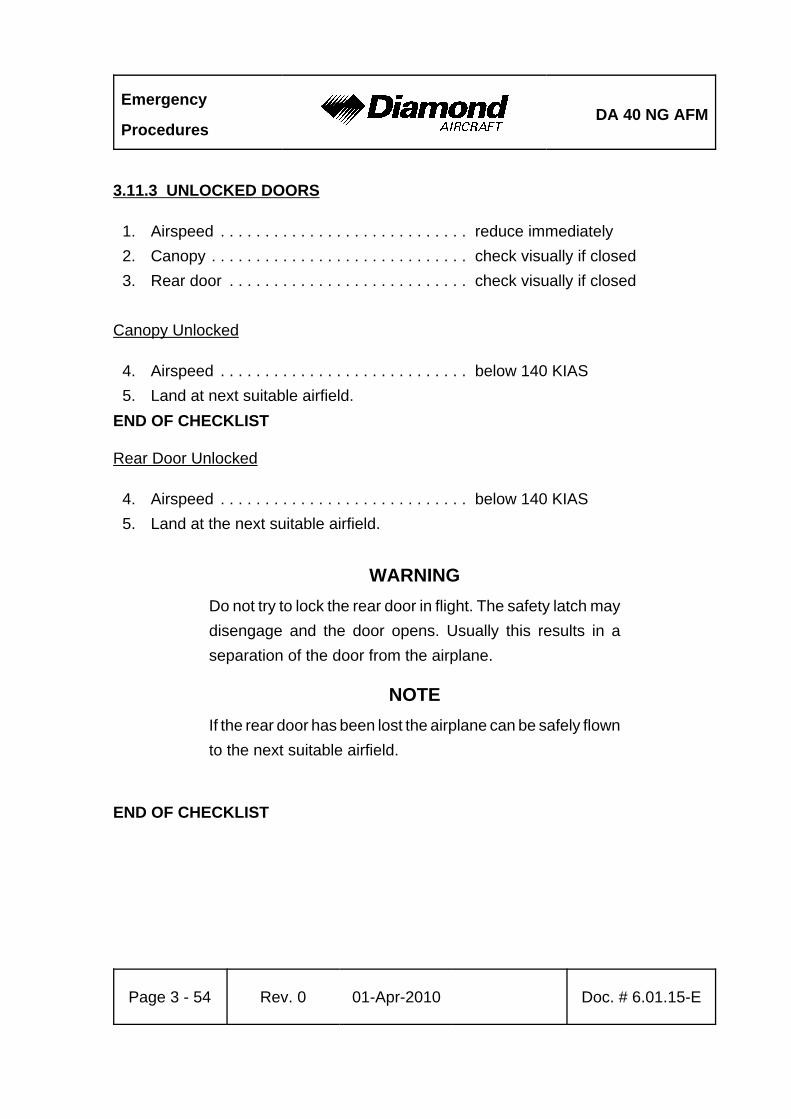
Emergency
ProceduresDA 40 NG AFM
Page 3 - 54 Rev. 0 01-Apr-2010 Doc. # 6.01.15-E
3.11.3 UNLOCKED DOORS
1. Airspeed . . . . . . . . . . . . . . . . . . . . . . . . . . . . reduce immediately2. Canopy . . . . . . . . . . . . . . . . . . . . . . . . . . . . . check visually if closed3. Rear door . . . . . . . . . . . . . . . . . . . . . . . . . . . check visually if closed
Canopy Unlocked
4. Airspeed . . . . . . . . . . . . . . . . . . . . . . . . . . . . below 140 KIAS5. Land at next suitable airfield.
END OF CHECKLIST
Rear Door Unlocked
4. Airspeed . . . . . . . . . . . . . . . . . . . . . . . . . . . . below 140 KIAS5. Land at the next suitable airfield.
WARNINGDo not try to lock the rear door in flight. The safety latch maydisengage and the door opens. Usually this results in aseparation of the door from the airplane.
NOTEIf the rear door has been lost the airplane can be safely flownto the next suitable airfield.
END OF CHECKLIST
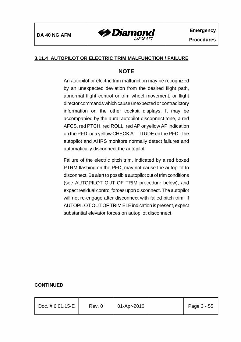
DA 40 NG AFMEmergency
Procedures
Doc. # 6.01.15-E Rev. 0 01-Apr-2010 Page 3 - 55
3.11.4 AUTOPILOT OR ELECTRIC TRIM MALFUNCTION / FAILURE
NOTEAn autopilot or electric trim malfunction may be recognizedby an unexpected deviation from the desired flight path,abnormal flight control or trim wheel movement, or flightdirector commands which cause unexpected or contradictoryinformation on the other cockpit displays. It may beaccompanied by the aural autopilot disconnect tone, a redAFCS, red PTCH, red ROLL, red AP or yellow AP indicationon the PFD, or a yellow CHECK ATTITUDE on the PFD. Theautopilot and AHRS monitors normally detect failures andautomatically disconnect the autopilot.
Failure of the electric pitch trim, indicated by a red boxedPTRM flashing on the PFD, may not cause the autopilot todisconnect. Be alert to possible autopilot out of trim conditions(see AUTOPILOT OUT OF TRIM procedure below), andexpect residual control forces upon disconnect. The autopilotwill not re-engage after disconnect with failed pitch trim. IfAUTOPILOT OUT OF TRIM ELE indication is present, expectsubstantial elevator forces on autopilot disconnect.
CONTINUED
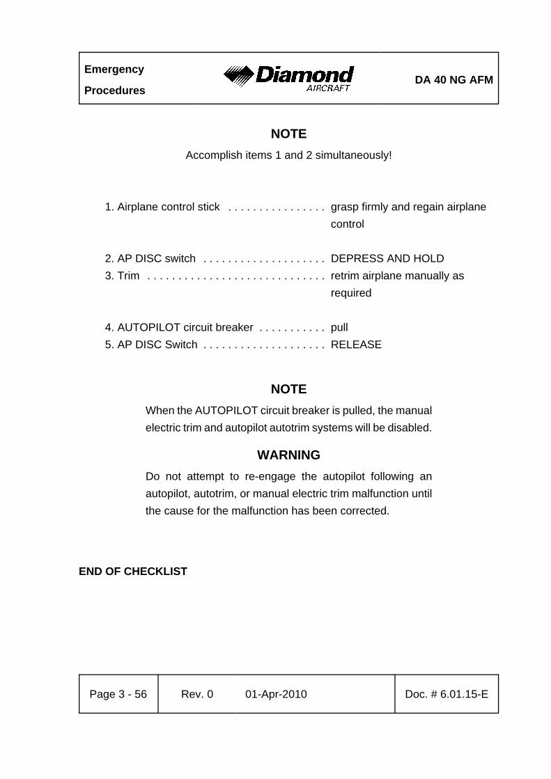
Emergency
ProceduresDA 40 NG AFM
Page 3 - 56 Rev. 0 01-Apr-2010 Doc. # 6.01.15-E
NOTEAccomplish items 1 and 2 simultaneously!
1. Airplane control stick . . . . . . . . . . . . . . . . grasp firmly and regain airplane control
2. AP DISC switch . . . . . . . . . . . . . . . . . . . . DEPRESS AND HOLD3. Trim . . . . . . . . . . . . . . . . . . . . . . . . . . . . . retrim airplane manually as
required
4. AUTOPILOT circuit breaker . . . . . . . . . . . pull5. AP DISC Switch . . . . . . . . . . . . . . . . . . . . RELEASE
NOTEWhen the AUTOPILOT circuit breaker is pulled, the manualelectric trim and autopilot autotrim systems will be disabled.
WARNINGDo not attempt to re-engage the autopilot following anautopilot, autotrim, or manual electric trim malfunction untilthe cause for the malfunction has been corrected.
END OF CHECKLIST

DA 40 NG AFMNormal Operating
Procedures
Doc. # 6.01.15-E Rev. 0 01-Apr-2010 Page 4A - 1
CHAPTER 4ANORMAL OPERATING PROCEDURES
Page
4A.1 INTRODUCTION . . . . . . . . . . . . . . . . . . . . . . . . . . . . . . . . . . . . . . 4A-34A.2 AIRSPEEDS FOR NORMAL OPERATING PROCEDURES . . . . . 4A-44A.3 ADVISORY ALERTS ON THE G1000 . . . . . . . . . . . . . . . . . . . . . . 4A-5
4A.3.1 ADVISORY / GENERAL . . . . . . . . . . . . . . . . . . . . . . . . . . 4A-54A.3.2 GLOW ON . . . . . . . . . . . . . . . . . . . . . . . . . . . . . . . . . . . . 4A-54A.3.3 FUEL XFER . . . . . . . . . . . . . . . . . . . . . . . . . . . . . . . . . . . 4A-54A.3.4 PFD/MFD/GIA FAN FAIL . . . . . . . . . . . . . . . . . . . . . . . . . 4A-5
4A.4 FLIGHT CHARACTERISTICS . . . . . . . . . . . . . . . . . . . . . . . . . . . . 4A-64A.5 DAILY CHECK . . . . . . . . . . . . . . . . . . . . . . . . . . . . . . . . . . . . . . . 4A-64A.6 CHECKLISTS FOR NORMAL OPERATING PROCEDURES . . . . 4A-7
4A.6.1 PRE-FLIGHT INSPECTION . . . . . . . . . . . . . . . . . . . . . . . 4A-74A.6.2 BEFORE STARTING ENGINE . . . . . . . . . . . . . . . . . . . . 4A-154A.6.3 STARTING ENGINE . . . . . . . . . . . . . . . . . . . . . . . . . . . . 4A-174A.6.4 BEFORE TAXIING . . . . . . . . . . . . . . . . . . . . . . . . . . . . . 4A-194A.6.5 TAXIING . . . . . . . . . . . . . . . . . . . . . . . . . . . . . . . . . . . . . 4A-214A.6.6 BEFORE TAKE-OFF . . . . . . . . . . . . . . . . . . . . . . . . . . . 4A-224A.6.7 TAKE-OFF . . . . . . . . . . . . . . . . . . . . . . . . . . . . . . . . . . . 4A-274A.6.8 GFC 700 OPERATION . . . . . . . . . . . . . . . . . . . . . . . . . . 4A-294A.6.9 CLIMB . . . . . . . . . . . . . . . . . . . . . . . . . . . . . . . . . . . . . . . 4A-304A.6.10 CRUISE . . . . . . . . . . . . . . . . . . . . . . . . . . . . . . . . . . . . 4A-354A.6.11 FUEL TRANSFER . . . . . . . . . . . . . . . . . . . . . . . . . . . . 4A-404A.6.12 DESCENT . . . . . . . . . . . . . . . . . . . . . . . . . . . . . . . . . . 4A-414A.6.13 APPROACH & LANDING . . . . . . . . . . . . . . . . . . . . . . . 4A-464A.6.14 GO-AROUND . . . . . . . . . . . . . . . . . . . . . . . . . . . . . . . . 4A-52
Normal Operating
ProceduresDA 40 NG AFM
Page 4A - 2 Rev. 0 01-Apr-2010 Doc. # 6.01.15-E
4A.6.15 AFTER LANDING . . . . . . . . . . . . . . . . . . . . . . . . . . . . . 4A-544A.6.16 ENGINE SHUT-DOWN . . . . . . . . . . . . . . . . . . . . . . . . . 4A-554A.6.17 POST FLIGHT INSPECTION . . . . . . . . . . . . . . . . . . . . 4A-564A.6.18 PARKING . . . . . . . . . . . . . . . . . . . . . . . . . . . . . . . . . . . 4A-564A.6.19 FLIGHT IN RAIN . . . . . . . . . . . . . . . . . . . . . . . . . . . . . . 4A-574A.6.20 REFUELING . . . . . . . . . . . . . . . . . . . . . . . . . . . . . . . . . 4A-574A.6.21 FLIGHT AT HIGH ALTITUDE . . . . . . . . . . . . . . . . . . . . 4A-57
DA 40 NG AFMNormal Operating
Procedures
Doc. # 6.01.15-E Rev. 0 01-Apr-2010 Page 4A - 3
4A.1 INTRODUCTION
Chapter 4A contains checklists and describes procedures for the normal operation of theairplane.
NOTEReadability of the G1000 PFD and MFD displays may bedegraded when wearing polarizing sunglasses.
NOTENormal operating procedures for GFC 700 are described inthe Garmin G1000 Cockpit Reference Guide, P/N190-00953-00, Rev. 0 or later and the Garmin G1000 Pilot'sGuide for the Diamond DA 40 NG, P/N 190-00952-00, Rev. 0or later.
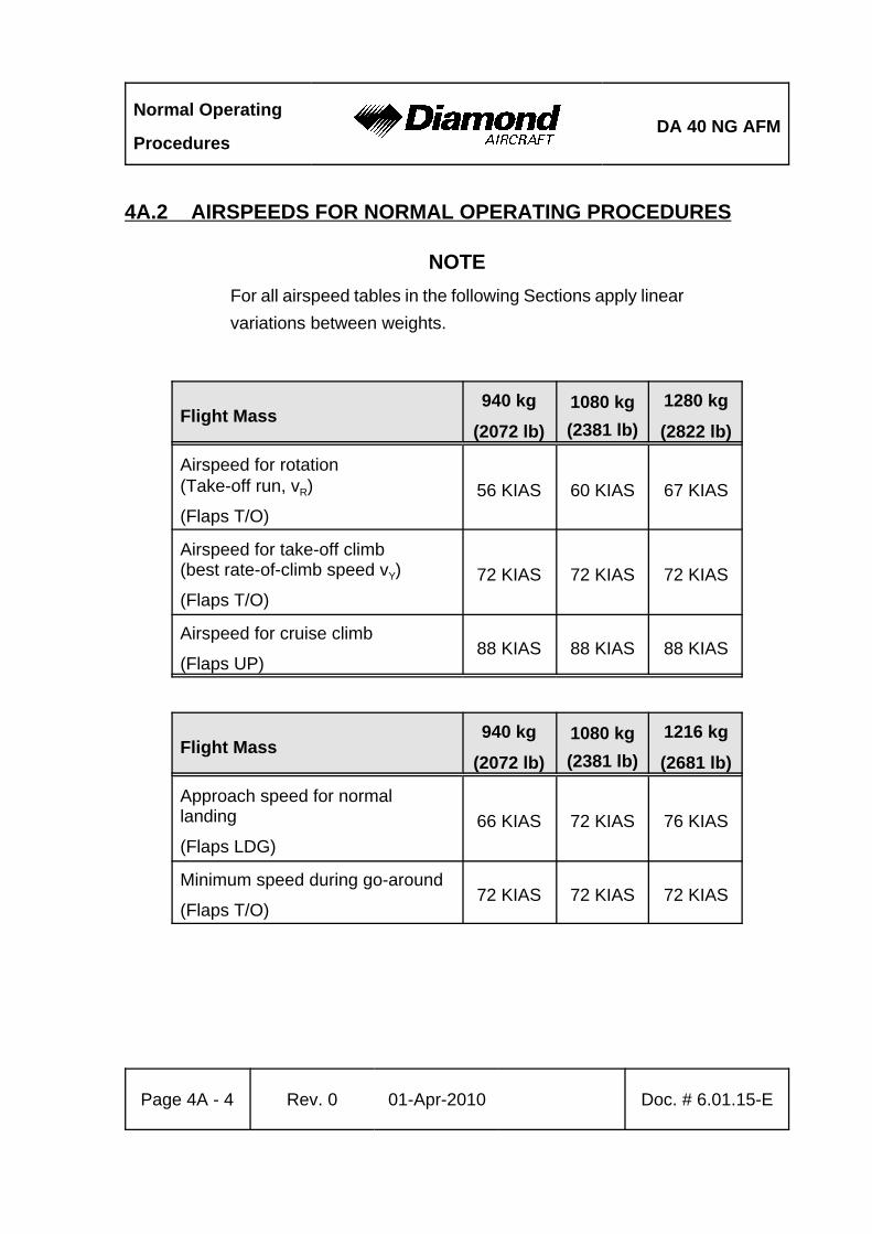
Normal Operating
ProceduresDA 40 NG AFM
Page 4A - 4 Rev. 0 01-Apr-2010 Doc. # 6.01.15-E
4A.2 AIRSPEEDS FOR NORMAL OPERATING PROCEDURES
NOTEFor all airspeed tables in the following Sections apply linearvariations between weights.
Flight Mass940 kg
(2072 lb)1080 kg(2381 lb)
1280 kg
(2822 lb)
Airspeed for rotation (Take-off run, vR)
(Flaps T/O)56 KIAS 60 KIAS 67 KIAS
Airspeed for take-off climb(best rate-of-climb speed vY)
(Flaps T/O)72 KIAS 72 KIAS 72 KIAS
Airspeed for cruise climb
(Flaps UP)88 KIAS 88 KIAS 88 KIAS
Flight Mass940 kg
(2072 lb)1080 kg(2381 lb)
1216 kg
(2681 lb)
Approach speed for normallanding
(Flaps LDG)66 KIAS 72 KIAS 76 KIAS
Minimum speed during go-around
(Flaps T/O)72 KIAS 72 KIAS 72 KIAS
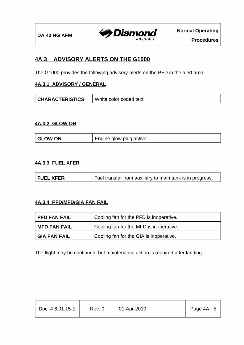
DA 40 NG AFMNormal Operating
Procedures
Doc. # 6.01.15-E Rev. 0 01-Apr-2010 Page 4A - 5
4A.3 ADVISORY ALERTS ON THE G1000
The G1000 provides the following advisory-alerts on the PFD in the alert area:
4A.3.1 ADVISORY / GENERAL
CHARACTERISTICS White color coded text.
4A.3.2 GLOW ON
GLOW ON Engine glow plug active.
4A.3.3 FUEL XFER
FUEL XFER Fuel transfer from auxiliary to main tank is in progress.
4A.3.4 PFD/MFD/GIA FAN FAIL
PFD FAN FAIL Cooling fan for the PFD is inoperative.
MFD FAN FAIL Cooling fan for the MFD is inoperative.
GIA FAN FAIL Cooling fan for the GIA is inoperative.
The flight may be continued, but maintenance action is required after landing.
Normal Operating
ProceduresDA 40 NG AFM
Page 4A - 6 Rev. 0 01-Apr-2010 Doc. # 6.01.15-E
4A.4 FLIGHT CHARACTERISTICS
The DA 40 NG is to be flown with "the feet on the pedals“, meaning that coordinated flightin all phases and configurations shall be supported by dedicated use of the rudder andailerons together.
4A.5 DAILY CHECK
Before the first flight of a day it must be ensured that the following checks are performed:
- On-condition check of the canopy, the rear door for cracks and major scratches.
- On-condition check of the lever arms of the canopy and the hinges of the rear door.
- Visual inspection of the locking bolts for proper movement with no backlash.
- Visual inspection of the rear door safety hook.
- Tire inflation pressure check : main wheels : 3.3 bar (48 PSI)
nose wheel : 3.1 bar (45 PSI)
- Visual inspection of the spinner and its attachment (including screws).
DA 40 NG AFMNormal Operating
Procedures
Doc. # 6.01.15-E Rev. 0 01-Apr-2010 Page 4A - 7
4A.6 CHECKLISTS FOR NORMAL OPERATING PROCEDURES
4A.6.1 PRE-FLIGHT INSPECTION
I. Cabin Check
a) MET, NAV, Mass & CG . . . . . . . . . . . . . . . . . flight planning completedb) Airplane documents . . . . . . . . . . . . . . . . . . . . complete and up-to-datec) ELECTRIC MASTER . . . . . . . . . . . . . . . . . . . OFF, pull out keyd) ENGINE MASTER . . . . . . . . . . . . . . . . . . . . . check OFFe) VOTER switch . . . . . . . . . . . . . . . . . . . . . . . . check AUTOf) Fuel valve . . . . . . . . . . . . . . . . . . . . . . . . . . . . locked, in NORMAL positiong) Front canopy & rear door . . . . . . . . . . . . . . . . clean, undamaged,
check locking mechanism functionh) All electrical equipment . . . . . . . . . . . . . . . . . OFFi) Circuit breakers . . . . . . . . . . . . . . . . . . . . . . . set in (if one has been pulled, check
reason)j) Power lever . . . . . . . . . . . . . . . . . . . . . . . . . . check condition, freedom of
movement, full travel and frictionadjustment
k) Power lever . . . . . . . . . . . . . . . . . . . . . . . . . . IDLEl) ELECTRIC MASTER . . . . . . . . . . . . . . . . . . . ONm) Fuel quantity . . . . . . . . . . . . . . . . . . . . . . . . . check, use alternate mean
NOTEIf the fuel quantity indicator reads 14 US gal, the correct fuelquantity must be determined with the fuel quantity measuringdevice. If this measurement is not carried out, the fuel quantityavailable for flight planning is 14 US gal.
CONTINUED
Normal Operating
ProceduresDA 40 NG AFM
Page 4A - 8 Rev. 0 01-Apr-2010 Doc. # 6.01.15-E
n) Position lights, strobe lights (ACL) . . . . . . . . . check OFFo) Taxi lights, landing lights . . . . . . . . . . . . . . . . check OFFp) ELECTRIC MASTER . . . . . . . . . . . . . . . . . . . OFFq) Foreign objects . . . . . . . . . . . . . . . . . . . . . . . checkr) Controls and trim . . . . . . . . . . . . . . . . . . . . . . free and corrects) Baggage . . . . . . . . . . . . . . . . . . . . . . . . . . . . stowed and secured
END OF CHECKLIST
DA 40 NG AFMNormal Operating
Procedures
Doc. # 6.01.15-E Rev. 0 01-Apr-2010 Page 4A - 9
II. Walk-Around Check, Visual Inspection
CAUTIONA visual inspection means: examination for damage, cracks,delamination, excessive play, load transmission, correctattachment and general condition. In addition control surfacesshould be checked for freedom of movement.
CAUTIONIn low ambient temperatures the airplane should becompletely cleared of ice, snow and similar accumulations.
CAUTIONPrior to flight, remove such items as control surfaces gustlock, Pitot cover, tow bar, etc.
1. Left Main Landing Gear:
a) Landing gear strut or fairing . . . . . . . . . . . . . . visual inspectionb) Wear, tread depth of tire . . . . . . . . . . . . . . . . checkc) Tire, wheel, brake . . . . . . . . . . . . . . . . . . . . . visual inspectiond) Brakes . . . . . . . . . . . . . . . . . . . . . . . . . . . . . . check for leakse) Slip marks . . . . . . . . . . . . . . . . . . . . . . . . . . . visual inspectionf) Chocks . . . . . . . . . . . . . . . . . . . . . . . . . . . . . . remove
CONTINUED
Normal Operating
ProceduresDA 40 NG AFM
Page 4A - 10 Rev. 0 01-Apr-2010 Doc. # 6.01.15-E
2. Left Wing:
a) Entire wing surface . . . . . . . . . . . . . . . . . . . . visual inspectionb) Step . . . . . . . . . . . . . . . . . . . . . . . . . . . . . . . . visual inspectionc) Air intake on lower surface . . . . . . . . . . . . . . . visual inspectiond) Openings on lower surface . . . . . . . . . . . . . . check for foreign objects and
for traces of fuel (if tank is full,fuel may spill over through thetank vent)
e) Tank drain . . . . . . . . . . . . . . . . . . . . . . . . . . . drain to check for water and sediment (drain until free ofcontamination)
f) Stall warning . . . . . . . . . . . . . . . . . . . . . . . . . check function (suction)g) Tank filler . . . . . . . . . . . . . . . . . . . . . . . . . . . . check closed
(for fuel qty. check usealternate means)
h) Tank air outlet in lower surface . . . . . . . . . . . visual inspectioni) Pitot probe . . . . . . . . . . . . . . . . . . . . . . . . . . . clean, orifices clearj) Landing/taxi light . . . . . . . . . . . . . . . . . . . . . . visual inspectionk) Wing let . . . . . . . . . . . . . . . . . . . . . . . . . . . . . visual inspectionl) Position light, strobe light (ACL) . . . . . . . . . . . visual inspectionm) Tie-down . . . . . . . . . . . . . . . . . . . . . . . . . . . . check, clearn) Aileron and linkage . . . . . . . . . . . . . . . . . . . . visual inspectiono) Aileron hinges and safety pin . . . . . . . . . . . . . visual inspectionp) Foreign objects in aileron paddle . . . . . . . . . . visual inspectionq) Trim tab . . . . . . . . . . . . . . . . . . . . . . . . . . . . . visual inspectionr) Flap and linkage . . . . . . . . . . . . . . . . . . . . . . . visual inspections) Flap hinges and safety pin . . . . . . . . . . . . . . . visual inspectiont) Static discharger . . . . . . . . . . . . . . . . . . . . . . visual inspection
CONTINUED
DA 40 NG AFMNormal Operating
Procedures
Doc. # 6.01.15-E Rev. 0 01-Apr-2010 Page 4A - 11
u) Ventilation inlet baffle (if installed) . . . . . . . . . . verify that the outside air temperaturepermits the use
v) Ventilation inlet baffle (if installed) . . . . . . . . . check for improper mounting or obvious damage
3. Fuselage, Left Side:
a) Canopy, left side . . . . . . . . . . . . . . . . . . . . . . visual inspectionb) Door lock (if installed) . . . . . . . . . . . . . . . . . . unlocked, key removedc) Rear cabin door & window . . . . . . . . . . . . . . . visual inspectiond) Fuselage skin . . . . . . . . . . . . . . . . . . . . . . . . . visual inspectione) Antennas . . . . . . . . . . . . . . . . . . . . . . . . . . . . visual inspectionf) Static source . . . . . . . . . . . . . . . . . . . . . . . . . check for blockage
4. Empennage:
a) Stabilizers and control surfaces . . . . . . . . . . . visual inspectionb) Hinges . . . . . . . . . . . . . . . . . . . . . . . . . . . . . . visual inspectionc) Elevator trim tab . . . . . . . . . . . . . . . . . . . . . . . visual inspection, check for movement
and safety wired) Rudder tab . . . . . . . . . . . . . . . . . . . . . . . . . . . visual inspectione) Tie-down . . . . . . . . . . . . . . . . . . . . . . . . . . . . check, clearf) Tail skid and lower fin . . . . . . . . . . . . . . . . . . visual inspectiong) Static dischargers . . . . . . . . . . . . . . . . . . . . . visual inspection
5. Fuselage, Right Side:
a) Fuselage skin . . . . . . . . . . . . . . . . . . . . . . . . . visual inspectionb) Static source . . . . . . . . . . . . . . . . . . . . . . . . . check for blockagec) Rear window . . . . . . . . . . . . . . . . . . . . . . . . . visual inspectiond) Canopy, right side . . . . . . . . . . . . . . . . . . . . . visual inspection
CONTINUED
Normal Operating
ProceduresDA 40 NG AFM
Page 4A - 12 Rev. 0 01-Apr-2010 Doc. # 6.01.15-E
6. Right Wing:
a) Flap and linkage . . . . . . . . . . . . . . . . . . . . . . . visual inspectionb) Flap hinges and safety pin . . . . . . . . . . . . . . . visual inspectionc) Aileron and linkage . . . . . . . . . . . . . . . . . . . . visual inspectiond) Aileron hinges and safety pin . . . . . . . . . . . . . visual inspectione) Foreign objects in aileron paddle . . . . . . . . . . visual inspectionf) Wing let . . . . . . . . . . . . . . . . . . . . . . . . . . . . . visual inspectiong) Position light, strobe light (ACL) . . . . . . . . . . . visual inspectionh) Tie-down . . . . . . . . . . . . . . . . . . . . . . . . . . . . check, cleari) Entire wing surface . . . . . . . . . . . . . . . . . . . . visual inspectionj) 2 stall strips on wing . . . . . . . . . . . . . . . . . . . . visual inspectionk) Tank air outlet in lower surface . . . . . . . . . . . visual inspectionl) Tank filler . . . . . . . . . . . . . . . . . . . . . . . . . . . . visual check
(for fuel qty. check use alternatemeans)
m) Openings on lower surface . . . . . . . . . . . . . . check for foreign objects and fortraces of fuel (if tank is full, fuelmay spill over through the tankvent)
n) Tank drain . . . . . . . . . . . . . . . . . . . . . . . . . . . drain to check for water and sediment (drain until free ofcontamination)
o) Step . . . . . . . . . . . . . . . . . . . . . . . . . . . . . . . . visual inspectionp) Static discharger . . . . . . . . . . . . . . . . . . . . . . visual inspection
CONTINUED
DA 40 NG AFMNormal Operating
Procedures
Doc. # 6.01.15-E Rev. 0 01-Apr-2010 Page 4A - 13
7. Right Main Landing Gear:
a) Landing gear strut or fairing . . . . . . . . . . . . . . visual inspectionb) Wear, tread depth of tires . . . . . . . . . . . . . . . checkc) Tire, wheel, brake . . . . . . . . . . . . . . . . . . . . . visual inspectiond) Brakes . . . . . . . . . . . . . . . . . . . . . . . . . . . . . . check for leakse) Slip marks . . . . . . . . . . . . . . . . . . . . . . . . . . . visual inspectionf) Chocks . . . . . . . . . . . . . . . . . . . . . . . . . . . . . . remove
8. Front Fuselage:
a) Engine oil level . . . . . . . . . . . . . . . . . . . . . . . . check dipstick (inspection door on left side)
b) Gearbox oil level . . . . . . . . . . . . . . . . . . . . . . check visually (inspection door on left side)
c) Cowling . . . . . . . . . . . . . . . . . . . . . . . . . . . . . visual inspectiond) 4 air intakes on front cowling . . . . . . . . . . . . . checke) 2 air intakes on RH fuselage and cowling . . . checkf) 1 air intake on LH fuselage . . . . . . . . . . . . . . check g) Propeller . . . . . . . . . . . . . . . . . . . . . . . . . . . . visual inspection
WARNINGNever rotate the propeller by hand.
f) Spinner including attachment screws . . . . . . . visual inspectiong) Nose landing gear strut . . . . . . . . . . . . . . . . . visual inspection
CONTINUED
Normal Operating
ProceduresDA 40 NG AFM
Page 4A - 14 Rev. 0 01-Apr-2010 Doc. # 6.01.15-E
h) Winter baffle (if installed) . . . . . . . . . . . . . . . visual inspectioni) Tie-down (if installed) . . . . . . . . . . . . . . . . . . . check, clearj) Tire and wheel . . . . . . . . . . . . . . . . . . . . . . . . visual inspection,
check slip marksk) Wear, tread depth of tire . . . . . . . . . . . . . . . . checkl) Wheel fairing . . . . . . . . . . . . . . . . . . . . . . . . . visual inspectionm) Tow bar . . . . . . . . . . . . . . . . . . . . . . . . . . . . . removedn) Chocks . . . . . . . . . . . . . . . . . . . . . . . . . . . . . . removeo) Exhaust . . . . . . . . . . . . . . . . . . . . . . . . . . . . . visual inspection
WARNINGThe exhaust can cause burns when it is hot.
Underside:
p) Antennas . . . . . . . . . . . . . . . . . . . . . . . . . . . . visual inspectionq) Gascolator . . . . . . . . . . . . . . . . . . . . . . . . . . . pull down on drain to check for
water and sediment (drain untilfree of contamination)
r) Venting pipes . . . . . . . . . . . . . . . . . . . . . . . . . check for blockages) Fuselage underside . . . . . . . . . . . . . . . . . . . . check for excessive contamination
particularly by oil, fuel or other fluids
END OF CHECKLIST
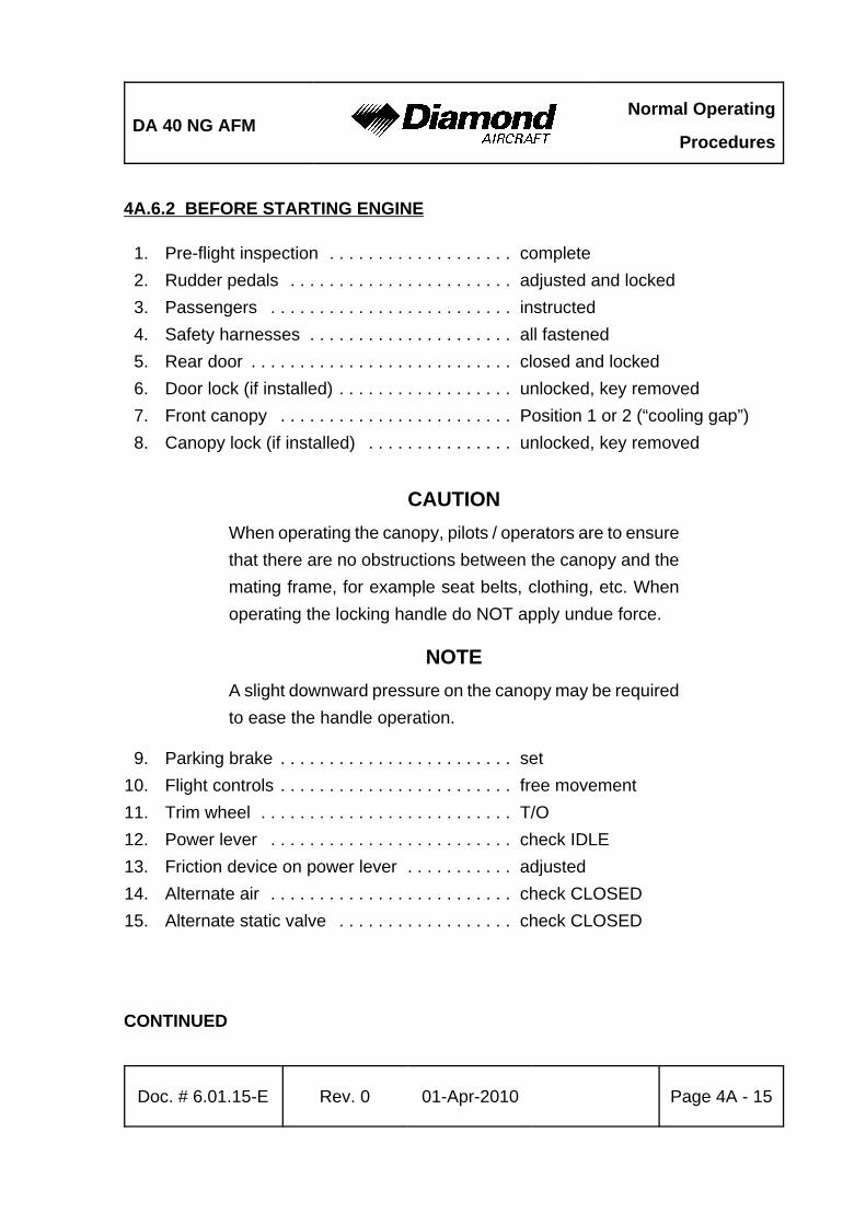
DA 40 NG AFMNormal Operating
Procedures
Doc. # 6.01.15-E Rev. 0 01-Apr-2010 Page 4A - 15
4A.6.2 BEFORE STARTING ENGINE
1. Pre-flight inspection . . . . . . . . . . . . . . . . . . . complete2. Rudder pedals . . . . . . . . . . . . . . . . . . . . . . . adjusted and locked3. Passengers . . . . . . . . . . . . . . . . . . . . . . . . . instructed4. Safety harnesses . . . . . . . . . . . . . . . . . . . . . all fastened5. Rear door . . . . . . . . . . . . . . . . . . . . . . . . . . . closed and locked6. Door lock (if installed) . . . . . . . . . . . . . . . . . . unlocked, key removed7. Front canopy . . . . . . . . . . . . . . . . . . . . . . . . Position 1 or 2 (“cooling gap”)8. Canopy lock (if installed) . . . . . . . . . . . . . . . unlocked, key removed
CAUTIONWhen operating the canopy, pilots / operators are to ensurethat there are no obstructions between the canopy and themating frame, for example seat belts, clothing, etc. Whenoperating the locking handle do NOT apply undue force.
NOTEA slight downward pressure on the canopy may be requiredto ease the handle operation.
9. Parking brake . . . . . . . . . . . . . . . . . . . . . . . . set10. Flight controls . . . . . . . . . . . . . . . . . . . . . . . . free movement11. Trim wheel . . . . . . . . . . . . . . . . . . . . . . . . . . T/O12. Power lever . . . . . . . . . . . . . . . . . . . . . . . . . check IDLE13. Friction device on power lever . . . . . . . . . . . adjusted14. Alternate air . . . . . . . . . . . . . . . . . . . . . . . . . check CLOSED15. Alternate static valve . . . . . . . . . . . . . . . . . . check CLOSED
CONTINUED
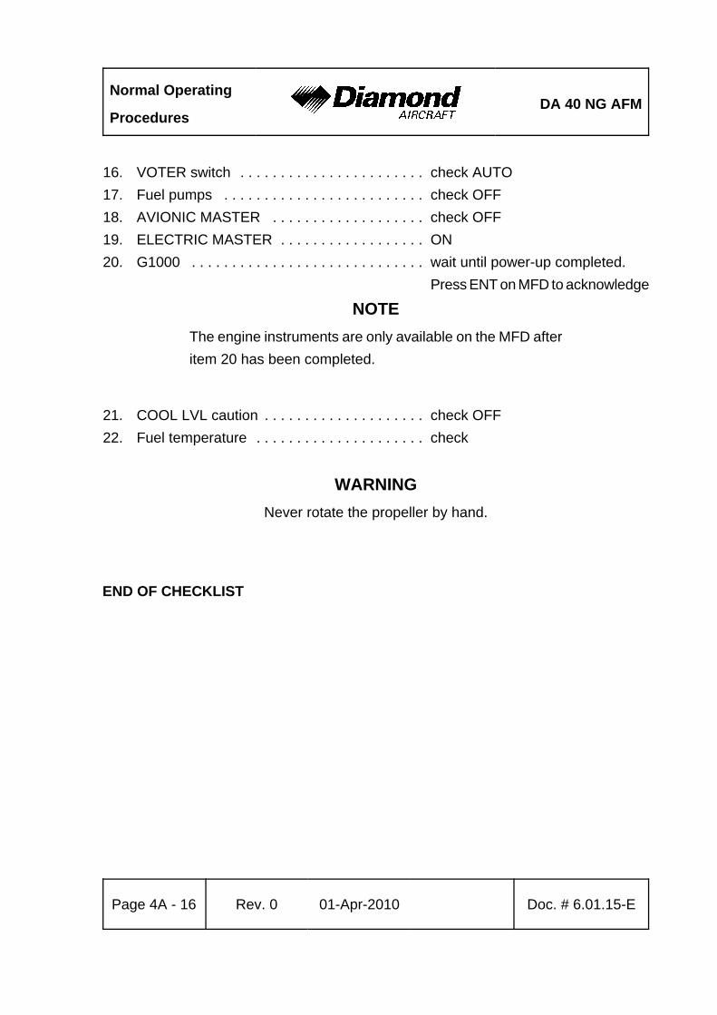
Normal Operating
ProceduresDA 40 NG AFM
Page 4A - 16 Rev. 0 01-Apr-2010 Doc. # 6.01.15-E
16. VOTER switch . . . . . . . . . . . . . . . . . . . . . . . check AUTO17. Fuel pumps . . . . . . . . . . . . . . . . . . . . . . . . . check OFF18. AVIONIC MASTER . . . . . . . . . . . . . . . . . . . check OFF19. ELECTRIC MASTER . . . . . . . . . . . . . . . . . . ON20. G1000 . . . . . . . . . . . . . . . . . . . . . . . . . . . . . wait until power-up completed.
Press ENT on MFD to acknowledge
NOTEThe engine instruments are only available on the MFD afteritem 20 has been completed.
21. COOL LVL caution . . . . . . . . . . . . . . . . . . . . check OFF22. Fuel temperature . . . . . . . . . . . . . . . . . . . . . check
WARNINGNever rotate the propeller by hand.
END OF CHECKLIST
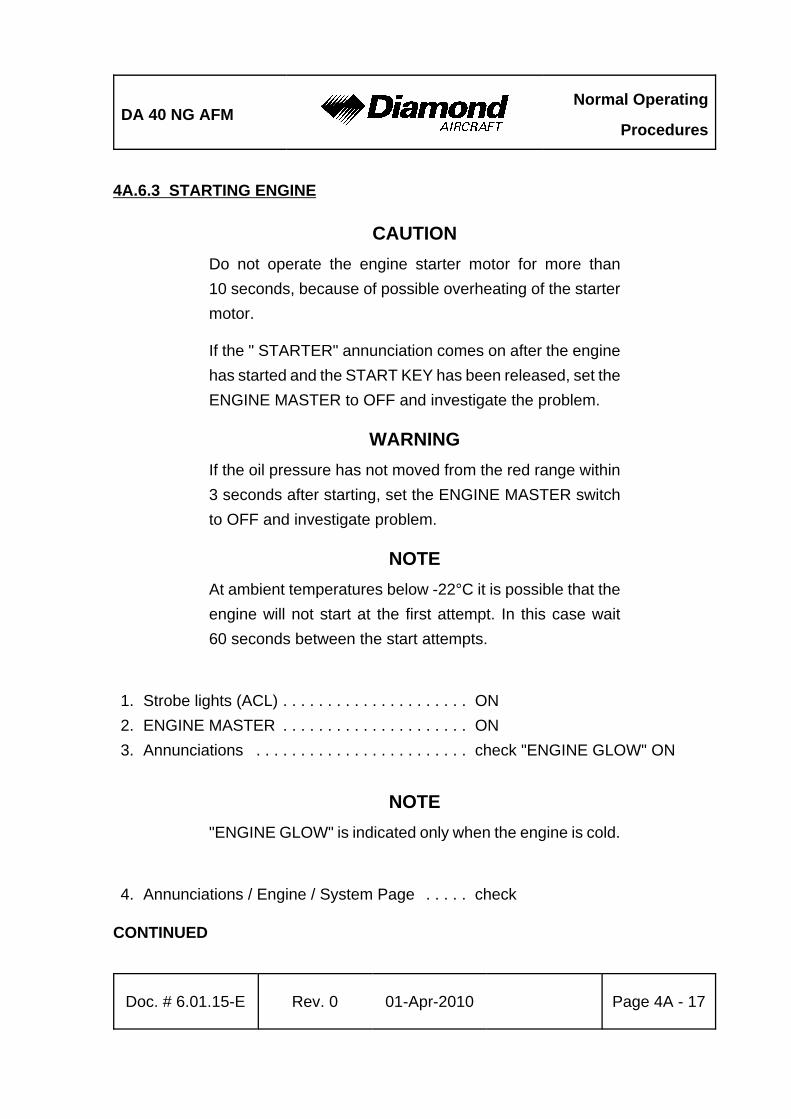
DA 40 NG AFMNormal Operating
Procedures
Doc. # 6.01.15-E Rev. 0 01-Apr-2010 Page 4A - 17
4A.6.3 STARTING ENGINE
CAUTIONDo not operate the engine starter motor for more than10 seconds, because of possible overheating of the startermotor.
If the " STARTER" annunciation comes on after the enginehas started and the START KEY has been released, set theENGINE MASTER to OFF and investigate the problem.
WARNINGIf the oil pressure has not moved from the red range within3 seconds after starting, set the ENGINE MASTER switchto OFF and investigate problem.
NOTEAt ambient temperatures below -22°C it is possible that theengine will not start at the first attempt. In this case wait60 seconds between the start attempts.
1. Strobe lights (ACL) . . . . . . . . . . . . . . . . . . . . . ON2. ENGINE MASTER . . . . . . . . . . . . . . . . . . . . . ON3. Annunciations . . . . . . . . . . . . . . . . . . . . . . . . check "ENGINE GLOW" ON
NOTE"ENGINE GLOW" is indicated only when the engine is cold.
4. Annunciations / Engine / System Page . . . . . check
CONTINUED
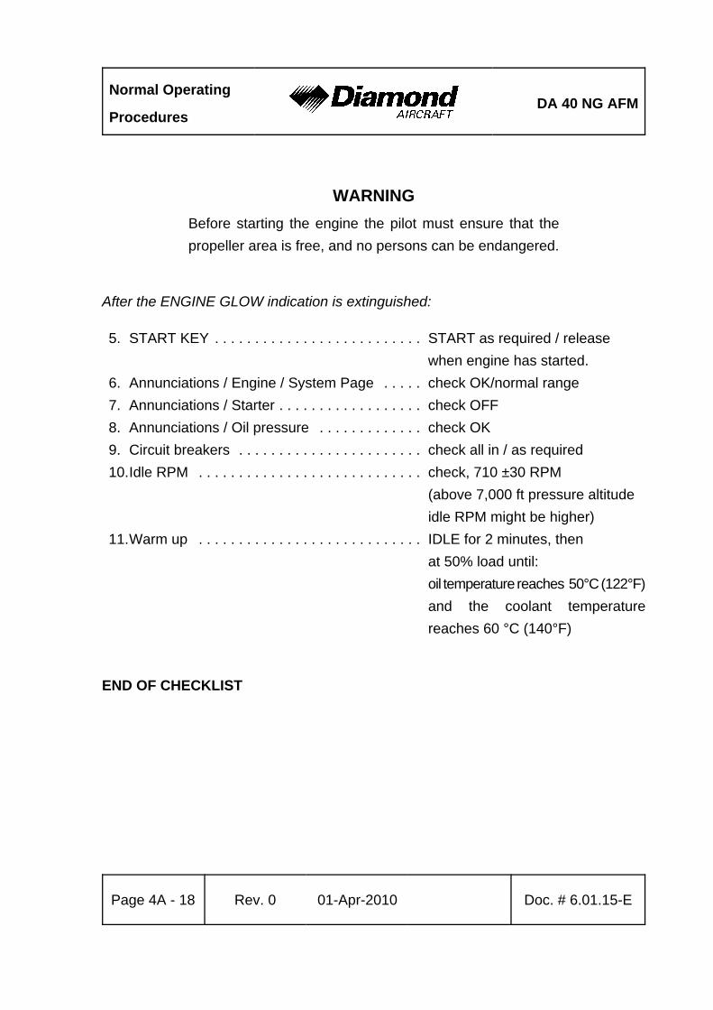
Normal Operating
ProceduresDA 40 NG AFM
Page 4A - 18 Rev. 0 01-Apr-2010 Doc. # 6.01.15-E
WARNINGBefore starting the engine the pilot must ensure that thepropeller area is free, and no persons can be endangered.
After the ENGINE GLOW indication is extinguished:
5. START KEY . . . . . . . . . . . . . . . . . . . . . . . . . . START as required / releasewhen engine has started.
6. Annunciations / Engine / System Page . . . . . check OK/normal range7. Annunciations / Starter . . . . . . . . . . . . . . . . . . check OFF8. Annunciations / Oil pressure . . . . . . . . . . . . . check OK9. Circuit breakers . . . . . . . . . . . . . . . . . . . . . . . check all in / as required10.Idle RPM . . . . . . . . . . . . . . . . . . . . . . . . . . . . check, 710 ±30 RPM
(above 7,000 ft pressure altitudeidle RPM might be higher)
11.Warm up . . . . . . . . . . . . . . . . . . . . . . . . . . . . IDLE for 2 minutes, then at 50% load until: oil temperature reaches 50°C (122°F)and the coolant temperaturereaches 60 °C (140°F)
END OF CHECKLIST
DA 40 NG AFMNormal Operating
Procedures
Doc. # 6.01.15-E Rev. 0 01-Apr-2010 Page 4A - 19
4A.6.4 BEFORE TAXIING
1. AVIONIC MASTER . . . . . . . . . . . . . . . . . . . . ON 2. Electrical equipment . . . . . . . . . . . . . . . . . . . . ON as required3. Flight instruments and avionics . . . . . . . . . . . set as required4. Flood light . . . . . . . . . . . . . . . . . . . . . . . . . . . ON, test function, as
required5. Pitot heating . . . . . . . . . . . . . . . . . . . . . . . . . . ON, check annunciation and observe
an increase in alternator load
6. Pitot heating . . . . . . . . . . . . . . . . . . . . . . . . . . OFF 7. Strobe lights (ACL's) . . . . . . . . . . . . . . . . . . . check ON8. Position lights, landing and taxi lights . . . . . . as required
CAUTIONWhen taxiing at close range to other airplanes, or during nightflight in clouds, fog or haze, the strobe lights should beswitched OFF. The position lights must always be switchedON during night flight.
9. Primary flight display (PFD) . . . . . . . . . . . . . . NO AUTOPILOT ANNUNCIATIONS
10. Autopilot disconnect tone . . . . . . . . . . . . . . . . NOTE
CONTINUED
Normal Operating
ProceduresDA 40 NG AFM
Page 4A - 20 Rev. 0 01-Apr-2010 Doc. # 6.01.15-E
NOTEThe AFCS automatically conducts a preflight self-test uponinitial power application. The preflight test is indicated by awhite boxed PFT on the PFD. Upon successful completionof the preflight test, the PFT is removed, the red AFCSannunciation is removed, and the autopilot disconnect tonesounds. If AFCS annunciation remains on or a failure of thepreflight test is indicated terminate flight preparation andinvestigate the problem.
11. MANUAL ELECTRIC TRIM - TEST as follows: Press the AP DISC button down and hold while commanding trim. Manual electric trim should not operate either nose up or nose down.
12. AUTOPILOT . . . . . . . . . . . . . . . . . . . . . . . . . . engage by pressing AP button13. AP DISC switch . . . . . . . . . . . . . . . . . . . . . . . press. verify that the autopilot
disconnects, check tone14. TRIM . . . . . . . . . . . . . . . . . . . . . . . . . . . . . . . set to take-off position manually
END OF CHECKLIST

DA 40 NG AFMNormal Operating
Procedures
Doc. # 6.01.15-E Rev. 0 01-Apr-2010 Page 4A - 21
4A.6.5 TAXIING
1. Parking brake . . . . . . . . . . . . . . . . . . . . . . . . . release2. Brakes . . . . . . . . . . . . . . . . . . . . . . . . . . . . . . test3. Flight instrumentation and avionics . . . . . . . . check for correct indications4. Fuel pumps . . . . . . . . . . . . . . . . . . . . . . . . . . check OFF
CAUTIONWhen taxiing on a poor surface select the lowest possibleRPM to avoid damage to the propeller from stones or similaritems.
END OF CHECKLIST
Normal Operating
ProceduresDA 40 NG AFM
Page 4A - 22 Rev. 0 01-Apr-2010 Doc. # 6.01.15-E
4A.6.6 BEFORE TAKE-OFF
1. Position airplane into wind if possible.2. Parking brake . . . . . . . . . . . . . . . . . . . . . . . . . set3. Safety harnesses . . . . . . . . . . . . . . . . . . . . . . fastened4. Rear door . . . . . . . . . . . . . . . . . . . . . . . . . . . . check closed and locked
CAUTIONWhen operating the canopy, pilots/operators must ensure thatthere are no obstructions between the canopy and the matingframe, for example seat belts, clothing, etc. When operatingthe locking handle do NOT apply undue force.
A slight downward pressure on the canopy may be requiredto ease the handle operation.
5. Front canopy . . . . . . . . . . . . . . . . . . . . . . . . . closed and locked6. Door warning (DOOR OPEN) . . . . . . . . . . . . check no indication7. Annunciations / Engine / System Page . . . . . check OK / normal range
(except oil pressure may be in theyellow range with a warm engineand power lever set to IDLE)
8. Circuit breakers . . . . . . . . . . . . . . . . . . . . . . . check pressed in9. Longitudinal trim . . . . . . . . . . . . . . . . . . . . . . . set T/O
10. Fuel valve . . . . . . . . . . . . . . . . . . . . . . . . . . . . check NORMAL11. FLAPS . . . . . . . . . . . . . . . . . . . . . . . . . . . . . . check function & indicator /
set T/O12. Flight controls . . . . . . . . . . . . . . . . . . . . . . . . . unrestricted free movement,
correct sense13. Pitot heating . . . . . . . . . . . . . . . . . . . . . . . . . . ON, if required14. Landing light . . . . . . . . . . . . . . . . . . . . . . . . . . ON, if requiredCONTINUED
DA 40 NG AFMNormal Operating
Procedures
Doc. # 6.01.15-E Rev. 0 01-Apr-2010 Page 4A - 23
ECU / Fuel Pump Test Sequence:
CAUTIONIf the ECU A/B FAIL indicators do not illuminate during thetest sequence there is a malfunction in the engine controlsystem. Terminate flight preparation.
The whole test procedure must be completed without anyerror (ECU A/B FAIL extinguished after test completion). Incase the test procedure aborts with an error indication (oneor both ECU A/B FAIL indicators remain ON) terminate flightpreparation, even if the engine seems to run smoothly afterthe test procedure.
CAUTIONDuring the test sequence the engine will produce thrusttherefore the parking brake must be set.
NOTEThe engine oil temperature has to be in the green rangebefore starting the test sequence.
Releasing the ECU TEST BUTTON or manipulating the powerlever before the test sequence is completed will abort the testsequence.
During the following ECU and fuel pump test, a shake of theengine might occur.
CONTINUED
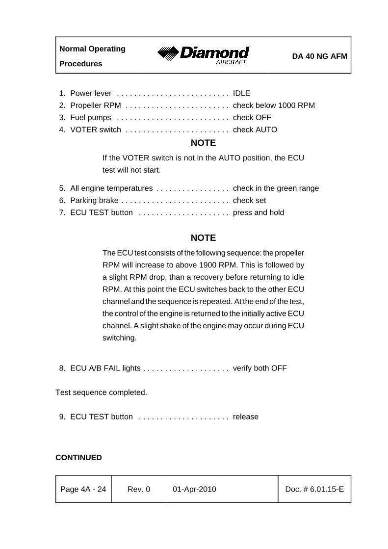
Normal Operating
ProceduresDA 40 NG AFM
Page 4A - 24 Rev. 0 01-Apr-2010 Doc. # 6.01.15-E
1. Power lever . . . . . . . . . . . . . . . . . . . . . . . . . . IDLE2. Propeller RPM . . . . . . . . . . . . . . . . . . . . . . . . check below 1000 RPM3. Fuel pumps . . . . . . . . . . . . . . . . . . . . . . . . . . check OFF4. VOTER switch . . . . . . . . . . . . . . . . . . . . . . . . check AUTO
NOTEIf the VOTER switch is not in the AUTO position, the ECUtest will not start.
5. All engine temperatures . . . . . . . . . . . . . . . . . check in the green range6. Parking brake . . . . . . . . . . . . . . . . . . . . . . . . . check set7. ECU TEST button . . . . . . . . . . . . . . . . . . . . . press and hold
NOTEThe ECU test consists of the following sequence: the propellerRPM will increase to above 1900 RPM. This is followed bya slight RPM drop, than a recovery before returning to idleRPM. At this point the ECU switches back to the other ECUchannel and the sequence is repeated. At the end of the test,the control of the engine is returned to the initially active ECUchannel. A slight shake of the engine may occur during ECUswitching.
8. ECU A/B FAIL lights . . . . . . . . . . . . . . . . . . . . verify both OFF
Test sequence completed.
9. ECU TEST button . . . . . . . . . . . . . . . . . . . . . release
CONTINUED

DA 40 NG AFMNormal Operating
Procedures
Doc. # 6.01.15-E Rev. 0 01-Apr-2010 Page 4A - 25
NOTEBy switching between ECU A and B the two independentelectrical fuel pumps are switched over as well.
10.VOTER switch . . . . . . . . . . . . . . . . . . . . . . . . ECU A 11.Engine . . . . . . . . . . . . . . . . . . . . . . . . . . . . . . check running without a change
(shake may occur)12.VOTER switch . . . . . . . . . . . . . . . . . . . . . . . . AUTO 13.Engine . . . . . . . . . . . . . . . . . . . . . . . . . . . . . . check running without a change
(shake may occur)14.VOTER switch . . . . . . . . . . . . . . . . . . . . . . . . ECU B15.Engine . . . . . . . . . . . . . . . . . . . . . . . . . . . . . . check running without a change
(shake may occur)16.VOTER switch . . . . . . . . . . . . . . . . . . . . . . . . AUTO
CAUTIONRunning the engine with the VOTER switch on ECU A orECU B, other than for this test or in an emergency isprohibited. The engine control system redundancy is onlygiven with the VOTER switch set to AUTO.
CONTINUED
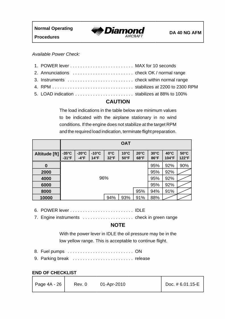
Normal Operating
ProceduresDA 40 NG AFM
Page 4A - 26 Rev. 0 01-Apr-2010 Doc. # 6.01.15-E
Available Power Check:
1. POWER lever . . . . . . . . . . . . . . . . . . . . . . . . . MAX for 10 seconds2. Annunciations . . . . . . . . . . . . . . . . . . . . . . . . check OK / normal range3. Instruments . . . . . . . . . . . . . . . . . . . . . . . . . . check within normal range4. RPM . . . . . . . . . . . . . . . . . . . . . . . . . . . . . . . . stabilizes at 2200 to 2300 RPM5. LOAD indication . . . . . . . . . . . . . . . . . . . . . . . stabilizes at 88% to 100%
CAUTIONThe load indications in the table below are minimum valuesto be indicated with the airplane stationary in no windconditions. If the engine does not stabilize at the target RPMand the required load indication, terminate flight preparation.
OAT
Altitude [ft] -35°C -31°F
-20°C-4°F
-10°C14°F
0°C32°F
10°C50°F
20°C68°F
30°C86°F
40°C104°F
50°C122°F
0
96%
95% 92% 90%2000 95% 92%4000 95% 92%6000 95% 92%8000 95% 94% 91%10000 94% 93% 91% 88%
6. POWER lever . . . . . . . . . . . . . . . . . . . . . . . . . IDLE7. Engine instruments . . . . . . . . . . . . . . . . . . . . check in green range
NOTEWith the power lever in IDLE the oil pressure may be in thelow yellow range. This is acceptable to continue flight.
8. Fuel pumps . . . . . . . . . . . . . . . . . . . . . . . . . . ON9. Parking break . . . . . . . . . . . . . . . . . . . . . . . . release
END OF CHECKLIST
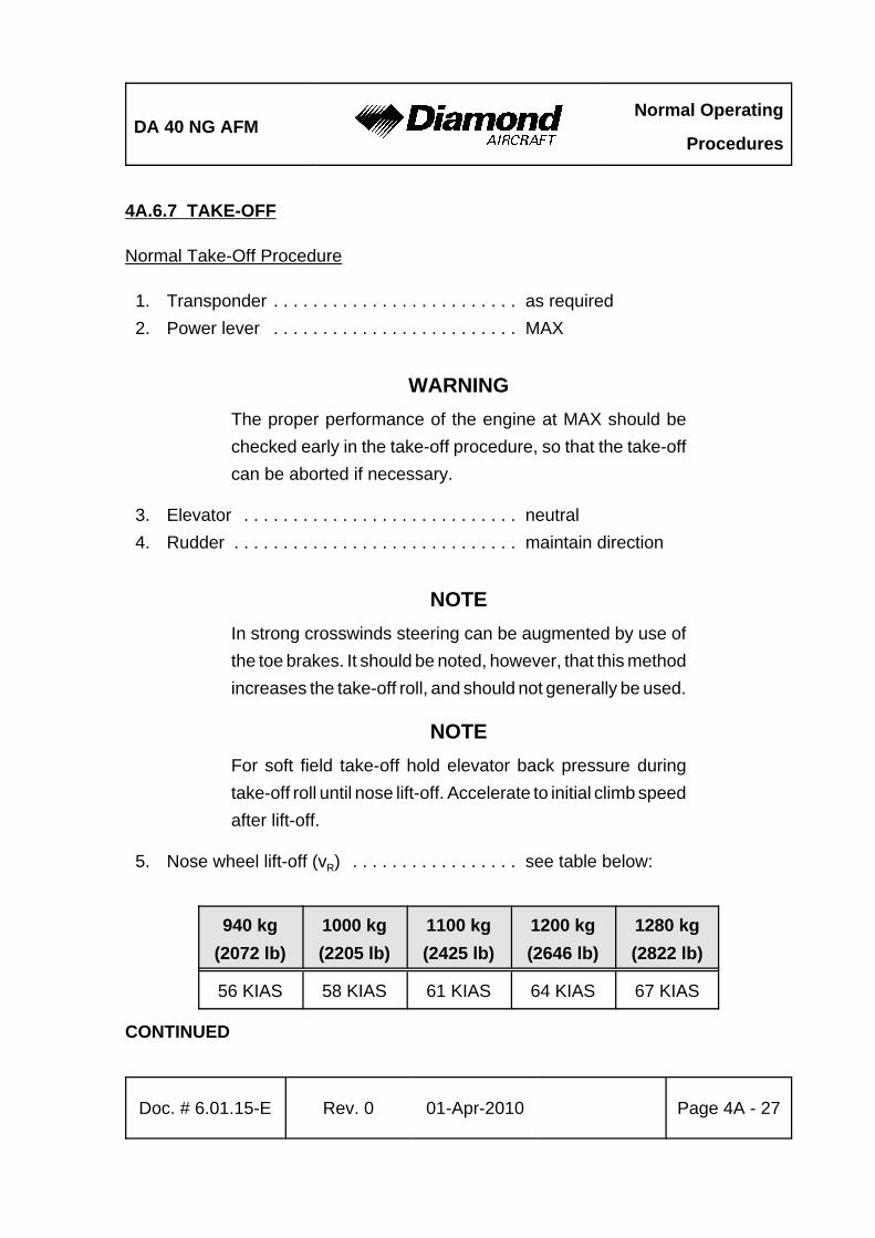
DA 40 NG AFMNormal Operating
Procedures
Doc. # 6.01.15-E Rev. 0 01-Apr-2010 Page 4A - 27
4A.6.7 TAKE-OFF
Normal Take-Off Procedure
1. Transponder . . . . . . . . . . . . . . . . . . . . . . . . . as required2. Power lever . . . . . . . . . . . . . . . . . . . . . . . . . MAX
WARNINGThe proper performance of the engine at MAX should bechecked early in the take-off procedure, so that the take-offcan be aborted if necessary.
3. Elevator . . . . . . . . . . . . . . . . . . . . . . . . . . . . neutral4. Rudder . . . . . . . . . . . . . . . . . . . . . . . . . . . . . maintain direction
NOTEIn strong crosswinds steering can be augmented by use ofthe toe brakes. It should be noted, however, that this methodincreases the take-off roll, and should not generally be used.
NOTEFor soft field take-off hold elevator back pressure duringtake-off roll until nose lift-off. Accelerate to initial climb speedafter lift-off.
5. Nose wheel lift-off (vR) . . . . . . . . . . . . . . . . . see table below:
940 kg(2072 lb)
1000 kg(2205 lb)
1100 kg(2425 lb)
1200 kg(2646 lb)
1280 kg(2822 lb)
56 KIAS 58 KIAS 61 KIAS 64 KIAS 67 KIAS
CONTINUED
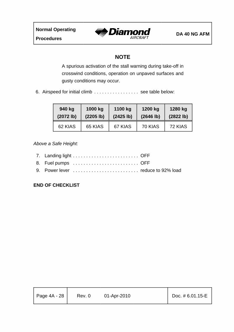
Normal Operating
ProceduresDA 40 NG AFM
Page 4A - 28 Rev. 0 01-Apr-2010 Doc. # 6.01.15-E
NOTEA spurious activation of the stall warning during take-off incrosswind conditions, operation on unpaved surfaces andgusty conditions may occur.
6. Airspeed for initial climb . . . . . . . . . . . . . . . . . see table below:
940 kg(2072 lb)
1000 kg(2205 lb)
1100 kg(2425 lb)
1200 kg(2646 lb)
1280 kg(2822 lb)
62 KIAS 65 KIAS 67 KIAS 70 KIAS 72 KIAS
Above a Safe Height:
7. Landing light . . . . . . . . . . . . . . . . . . . . . . . . . OFF8. Fuel pumps . . . . . . . . . . . . . . . . . . . . . . . . . OFF9. Power lever . . . . . . . . . . . . . . . . . . . . . . . . . reduce to 92% load
END OF CHECKLIST
DA 40 NG AFMNormal Operating
Procedures
Doc. # 6.01.15-E Rev. 0 01-Apr-2010 Page 4A - 29
4A.6.8 GFC 700 OPERATION
WARNINGIt is the responsibility of the pilot in command to monitor theautopilot when it is engaged. The pilot should be preparedto immediately disconnect the autopilot and to take promptcorrective action in the event of unexpected or unusualautopilot behavior. Do not attempt to manually fly the airplanewith the autopilot engaged. The autopilot servos will opposepilot input and will trim opposite the direction of pilot input(pitch axis only). This could lead to a significant out-of-trimcondition. Disconnect the autopilot if manual control isdesired. The pilot in command must use proper autopilotmodes and proper engine power settings to ensure thatairplane speed is maintained between 70 KIAS and 165 KIAS.It will be necessary to change engine power to maintain thedesired rate of descent when operating at 165 KIAS. Observethe minimum autopilot operating speed of 70 KIAS Operationin pitch (PIT) or vertical speed (VS) modes below this speedcan result in an airplane stall. If indications of an airplane stallare present, including stall warning horn, loss of controleffectiveness or airframe buffet, disconnect the autopilot andmanually return the airplane to stabilized flight prior tore-engaging the autopilot.
Normal Operating
ProceduresDA 40 NG AFM
Page 4A - 30 Rev. 0 01-Apr-2010 Doc. # 6.01.15-E
4A.6.9 CLIMB
Procedure for Take-off Climb
1. Flaps . . . . . . . . . . . . . . . . . . . . . . . . . . . . . . T/O2. Airspeed . . . . . . . . . . . . . . . . . . . . . . . . . . . . 72 KIAS 3. Power lever . . . . . . . . . . . . . . . . . . . . . . . . . 92% or maximum 2100 RPM4. Annunciations/Engine/System Page . . . . . . monitor5. Rudder . . . . . . . . . . . . . . . . . . . . . . . . . . . . . as required
CAUTIONIf the oil temperature and/or coolant temperature reaches theyellow range during climb, flight should be continued with anairspeed increased by 5 kt and power reduced by 10 %(reduced climb rate) for better engine cooling.
NOTEOperating in the gearbox cautionary range is permitted.However, prolonged operation is not recommended.
END OF CHECKLIST
Cruise Climb
1. Flaps . . . . . . . . . . . . . . . . . . . . . . . . . . . . . . UP2. Airspeed . . . . . . . . . . . . . . . . . . . . . . . . . . . . 88 KIAS3. Power lever . . . . . . . . . . . . . . . . . . . . . . . . . 92% or maximum 2100 RPM4. Annunciations/Engine/System Page . . . . . . monitor5. Rudder . . . . . . . . . . . . . . . . . . . . . . . . . . . . . as required
END OF CHECKLIST
DA 40 NG AFMNormal Operating
Procedures
Doc. # 6.01.15-E Rev. 0 01-Apr-2010 Page 4A - 31
GFC 700 Operation During Climb
NOTEThe NOSE UP and NOSE DN buttons on the mode controlleron the MFD are referenced to airplane movement. The NOSEUP button will increase the reference pitch attitude, increasethe reference vertical speed and decrease the referenceairspeed. Likewise, the NOSE DN button will decrease thereference pitch attitude, decrease the reference verticalspeed, and increase the reference airspeed.
a) Vertical Speed (VS)
1. Altitude preselect . . . . . . . . . . . . . . . . . . . . . set to desired altitude 2. Mode controller . . . . . . . . . . . . . . . . . . . . . . select VS on mode controller3. Vertical speed reference . . . . . . . . . . . . . . . adjust using NOSE UP and
NOSE DN buttons4. White ALT (altitude preselect armed) . . . . . . note on PFD5. Green ALT . . . . . . . . . . . . . . . . . . . . . . . . . . verify upon altitude capture
NOTEIf the altitude preselect is not changed before selecting VS,the autopilot may re-capture the current altitude immediatelyafter entering VS mode. Always ensure that the altitudepreselect is adjusted prior to selecting VS.
The vertical speed mode is limited to 1500 ft/min climb and3000 ft/min descent. Use engine power to maintainappropriate airplane speed. If the CWS switch is used whilein VS mode, the VS reference will change to the verticalspeed when the CWS switch is released.
END OF CHECKLIST
Normal Operating
ProceduresDA 40 NG AFM
Page 4A - 32 Rev. 0 01-Apr-2010 Doc. # 6.01.15-E
b) Flight Level Change (FLC)
1. Altitude preselect . . . . . . . . . . . . . . . . . . . . . set to desired altitude 2. Mode controller . . . . . . . . . . . . . . . . . . . . . . select FLC on mode controller3. Airspeed speed reference . . . . . . . . . . . . . . adjust using NOSE UP
and NOSE DN buttons 4. White ALT (altitude preselect armed) . . . . . . note on PFD5. Green ALT . . . . . . . . . . . . . . . . . . . . . . . . . . verify upon altitude capture
NOTEIf the altitude preselect is not changed before selecting FLC,the autopilot may re-capture the current altitude immediatelyafter entering FLC mode. Always ensure that the altitudepreselect is adjusted prior to selecting FLC.
If the airspeed reference cannot be maintained withoutdeviating away from the selected altitude, the system willmaintain level flight until the power or reference is changedto allow climbing or descending towards the selected altitude.
The FLC mode is limited to airspeeds between 70 KIAS and165 KIAS. Use engine power to maintain appropriate verticalspeed. If the CWS switch is used while in FLC mode, theairspeed reference will change to the airspeed when the CWSswitch is released.
END OF CHECKLIST
DA 40 NG AFMNormal Operating
Procedures
Doc. # 6.01.15-E Rev. 0 01-Apr-2010 Page 4A - 33
c) To Capture a Selected Altitude:
1. Altimeter setting . . . . . . . . . . . . . . . . . . . . . . adjust to appropriate value2. Altitude preselect . . . . . . . . . . . . . . . . . . . . . set to desired altitude3. Vertical mode and reference . . . . . . . . . . . . select on mode controller 4. White ALT(altitude preselect armed) . . . . . . note on PFD5. Green ALT . . . . . . . . . . . . . . . . . . . . . . . . . . verify upon altitude capture
NOTEIn ALT mode, the autopilot will maintain the reference altitudeshown in the autopilot window of the PFD regardless of thealtitude in the altitude preselect window or the altimeter'sbarometric pressure setting. If the altimeter setting ischanged, the autopilot will climb or descend to maintain thereference altitude.
END OF CHECKLIST
d) Altitude Hold
To maintain a selected altitude:
1. Altimeter setting . . . . . . . . . . . . . . . . . . . . . . adjust to appropriate value2. Reaching desired altitude . . . . . . . . . . . . . . select ALT on mode controller3. Green ALT . . . . . . . . . . . . . . . . . . . . . . . . . . verify on PFD
END OF CHECKLIST
Normal Operating
ProceduresDA 40 NG AFM
Page 4A - 34 Rev. 0 01-Apr-2010 Doc. # 6.01.15-E
e) Navigation Capture and Track:
1. Navigation source . . . . . . . . . . . . . . . . . . . . . select VOR or GPS using CDI button on PFD2. Course bearing pointer . . . . . . . . . . . . . . . . . set using course knob
(VOR only) 3. Intercept heading . . . . . . . . . . . . . . . . . . . . . . establish in HDG or ROL
mode (if required) 4. Mode controller . . . . . . . . . . . . . . . . . . . . . . . select NAV on mode controller 5. Green or white VOR or GPS annunciation . . . note on PFD 6. Vertical mode and reference . . . . . . . . . . . . . select on mode controller
NOTEIf the Course Deviation Indicator (CDI) is greater than onedot from center, the autopilot will arm the NAV mode andindicate VOR or GPS in white on the PFD. The pilot mustensure that the current heading will result in a capture of theselected course. If the CDI is one dot or less from center, theautopilot will enter the capture mode when the NAV buttonis pressed and annunciate VOR or GPS in green on the PFD.
END OF CHECKLIST
DA 40 NG AFMNormal Operating
Procedures
Doc. # 6.01.15-E Rev. 0 01-Apr-2010 Page 4A - 35
4A.6.10 CRUISE
1. Flaps . . . . . . . . . . . . . . . . . . . . . . . . . . . . . . UP2. POWER lever . . . . . . . . . . . . . . . . . . . . . . . . up to 92% or maximum 2100 RPM3. Trim . . . . . . . . . . . . . . . . . . . . . . . . . . . . . . . as required4. Fuel transfer . . . . . . . . . . . . . . . . . . . . . . . . . repeat as required (in accordance
with 4A.6.11 - FUEL TRANSFER)
NOTEThe engine manufacturer recommends a cruise power settingof 75 %.
NOTEProper operation of the transfer pump must be checked bymonitoring the fuel quantities (increasing in the MAIN tank,decreasing in the AUX tank, approx. 1 US gal per minute).
END OF CHECKLIST
Normal Operating
ProceduresDA 40 NG AFM
Page 4A - 36 Rev. 0 01-Apr-2010 Doc. # 6.01.15-E
GFC 700 Operation During Cruise
NOTEThe NOSE UP and NOSE DN buttons on the mode controlleron the MFD are referenced to airplane movement. The NOSEUP button will increase the reference pitch attitude, increasethe reference vertical speed and decrease the referenceairspeed. Likewise, the NOSE DN button will decrease thereference pitch attitude, decrease the reference verticalspeed, and increase the reference airspeed.
a) Vertical Speed (VS):
1. Altitude preselect . . . . . . . . . . . . . . . . . . . . . set to desired altitude 2. Mode controller . . . . . . . . . . . . . . . . . . . . . . select VS on mode controller3. Vertical speed reference . . . . . . . . . . . . . . . adjust using NOSE UP and
NOSE DN buttons4. White ALT (altitude preselect armed) . . . . . . note on PFD5. Green ALT . . . . . . . . . . . . . . . . . . . . . . . . . . verify upon altitude capture
NOTEIf the altitude preselect is not changed before selecting VS,the autopilot may re-capture the current altitude immediatelyafter entering VS mode. Always ensure that the altitudepreselect is adjusted prior to selecting VS.
The vertical speed mode is limited to 1500 ft/min climb and3000 ft/min descent. Use engine power to maintainappropriate airplane speed. If the CWS switch is used whilein VS mode, the VS reference will change to the verticalspeed when the CWS switch is released.
END OF CHECKLIST

DA 40 NG AFMNormal Operating
Procedures
Doc. # 6.01.15-E Rev. 0 01-Apr-2010 Page 4A - 37
b) Flight Level Change (FLC):
1. Altitude preselect . . . . . . . . . . . . . . . . . . . . . set to desired altitude 2. Mode controller . . . . . . . . . . . . . . . . . . . . . . select FLC on mode controller3. Airspeed speed reference . . . . . . . . . . . . . . adjust using NOSE UP
and NOSE DN buttons 4. White ALT (altitude preselect armed) . . . . . . note on PFD5. Green ALT . . . . . . . . . . . . . . . . . . . . . . . . . . verify upon altitude capture
NOTEIf the altitude preselect is not changed before selecting FLC,the autopilot may re-capture the current altitude immediatelyafter entering FLC mode. Always ensure that the altitudepreselect is adjusted prior to selecting FLC.
If the airspeed reference cannot be maintained withoutdeviating away from the selected altitude, the system willmaintain level flight until the power or reference is changedto allow climbing or descending towards the selected altitude.
The FLC mode is limited to airspeeds between 70 KIAS and165 KIAS. Use engine power to maintain appropriate verticalspeed. If the CWS switch is used while in FLC mode, theairspeed reference will change to the airspeed when the CWSswitch is released.
END OF CHECKLIST
Normal Operating
ProceduresDA 40 NG AFM
Page 4A - 38 Rev. 0 01-Apr-2010 Doc. # 6.01.15-E
c) To Capture a Selected Altitude:
1. Altimeter setting . . . . . . . . . . . . . . . . . . . . . . adjust to appropriate value2. Altitude preselect . . . . . . . . . . . . . . . . . . . . . set to desired altitude3. Vertical mode and reference . . . . . . . . . . . . select on mode controller 4. White ALT(altitude preselect armed) . . . . . . note on PFD5. Green ALT . . . . . . . . . . . . . . . . . . . . . . . . . . verify upon altitude capture
NOTEIn ALT mode, the autopilot will maintain the reference altitudeshown in the autopilot window of the PFD regardless of thealtitude in the altitude preselect window or the altimeter'sbarometric pressure setting. If the altimeter setting ischanged, the autopilot will climb or descend to maintain thereference altitude.
END OF CHECKLIST
d) Altitude Hold:
To maintain a selected altitude:
1. Altimeter setting . . . . . . . . . . . . . . . . . . . . . . adjust to appropriate value2. Reaching desired altitude . . . . . . . . . . . . . . select ALT on mode controller3. Green ALT . . . . . . . . . . . . . . . . . . . . . . . . . . verify on PFD
END OF CHECKLIST
DA 40 NG AFMNormal Operating
Procedures
Doc. # 6.01.15-E Rev. 0 01-Apr-2010 Page 4A - 39
e) Navigation Capture and Track:
1. Navigation source . . . . . . . . . . . . . . . . . . . . . select VOR or GPS using CDI button on PFD2. Course bearing pointer . . . . . . . . . . . . . . . . . set using course knob
(VOR only) 3. Intercept heading . . . . . . . . . . . . . . . . . . . . . . establish in HDG or ROL
mode (if required) 4. Mode controller . . . . . . . . . . . . . . . . . . . . . . . select NAV on mode controller 5. Green or white VOR or GPS annunciation . . . note on PFD 6. Vertical mode and reference . . . . . . . . . . . . . select on mode controller
NOTEIf the Course Deviation Indicator (CDI) is greater than onedot from center, the autopilot will arm the NAV mode andindicate VOR or GPS in white on the PFD. The pilot mustensure that the current heading will result in a capture of theselected course. If the CDI is one dot or less from center, theautopilot will enter the capture mode when the NAV buttonis pressed and annunciate VOR or GPS in green on the PFD.
END OF CHECKLIST
Normal Operating
ProceduresDA 40 NG AFM
Page 4A - 40 Rev. 0 01-Apr-2010 Doc. # 6.01.15-E
4A.6.11 FUEL TRANSFER
CAUTIONDuring normal operation fuel is taken from the main tank only.Therefore fuel must be transferred from the auxiliary tank tothe main tank by activating the fuel transfer pump. Thetransfer rate is approximately 60 US gal/h (227 liter/h).
1. Fuel transfer switch . . . . . . . . . . . . . . . . . . . . ON
NOTEThe transfer pump turns off automatically to avoid overfillingthe main tank. The switch remains in its position. If the pumpis not turned off, it will continue pumping each time the fuellevel in the main tank drops, but only as long as there is fuelin the auxiliary tank. The fuel transfer status light is illuminatedonly while the pump is running.
2. Fuel transfer switch . . . . . . . . . . . . . . . . . . . . OFF, if required
NOTEIf the fuel transfer status light starts to blink, the fuel transferpump must be switched off.
END OF CHECKLIST
DA 40 NG AFMNormal Operating
Procedures
Doc. # 6.01.15-E Rev. 0 01-Apr-2010 Page 4A - 41
4A.6.12 DESCENT
1. Power lever . . . . . . . . . . . . . . . . . . . . . . . . . as required 2. Airspeed . . . . . . . . . . . . . . . . . . . . . . . . . . . as required3. Trim . . . . . . . . . . . . . . . . . . . . . . . . . . . . . . . as required4. Annunciations / Engine / System Page . . . . monitor
END OF CHECKLIST

Normal Operating
ProceduresDA 40 NG AFM
Page 4A - 42 Rev. 0 01-Apr-2010 Doc. # 6.01.15-E
GFC700 Operation During Descent
NOTEThe NOSE UP and NOSE DN buttons on the mode controlleron the MFD are referenced to airplane movement. The NOSEUP button will increase the reference pitch attitude, increasethe reference vertical speed and decrease the referenceairspeed. Likewise, the NOSE DN button will decrease thereference pitch attitude, decrease the reference verticalspeed, and increase the reference airspeed.
a) Vertical Speed (VS):
1. Altitude preselect . . . . . . . . . . . . . . . . . . . . . set to desired altitude 2. Mode controller . . . . . . . . . . . . . . . . . . . . . . select VS on mode controller3. Vertical speed reference . . . . . . . . . . . . . . . adjust using NOSE UP and
NOSE DN buttons4. White ALT (altitude preselect armed) . . . . . . note on PFD5. Green ALT . . . . . . . . . . . . . . . . . . . . . . . . . . verify upon altitude capture
NOTEIf the altitude preselect is not changed before selecting VS,the autopilot may re-capture the current altitude immediatelyafter entering VS mode. Always ensure that the altitudepreselect is adjusted prior to selecting VS.
The vertical speed mode is limited to 1500 ft/min climb and3000 ft/min descent. Use engine power to maintainappropriate airplane speed. If the CWS switch is used whilein VS mode, the VS reference will change to the verticalspeed when the CWS switch is released.
END OF CHECKLIST
DA 40 NG AFMNormal Operating
Procedures
Doc. # 6.01.15-E Rev. 0 01-Apr-2010 Page 4A - 43
b) Flight Level Change (FLC):
1. Altitude preselect . . . . . . . . . . . . . . . . . . . . . set to desired altitude 2. Mode controller . . . . . . . . . . . . . . . . . . . . . . select FLC on mode controller3. Airspeed speed reference . . . . . . . . . . . . . . adjust using NOSE UP
and NOSE DN buttons 4. White ALT (altitude preselect armed) . . . . . . note on PFD5. Green ALT . . . . . . . . . . . . . . . . . . . . . . . . . . verify upon altitude capture
NOTEIf the altitude preselect is not changed before selecting FLC,the autopilot may re-capture the current altitude immediatelyafter entering FLC mode. Always ensure that the altitudepreselect is adjusted prior to selecting FLC.
If the airspeed reference cannot be maintained withoutdeviating away from the selected altitude, the system willmaintain level flight until the power or reference is changedto allow climbing or descending towards the selected altitude.
The FLC mode is limited to airspeeds between 70 KIAS and165 KIAS. Use engine power to maintain appropriate verticalspeed. If the CWS switch is used while in FLC mode, theairspeed reference will change to the airspeed when the CWSswitch is released.
END OF CHECKLIST

Normal Operating
ProceduresDA 40 NG AFM
Page 4A - 44 Rev. 0 01-Apr-2010 Doc. # 6.01.15-E
c) To Capture a Selected Altitude:
1. Altimeter setting . . . . . . . . . . . . . . . . . . . . . . adjust to appropriate value2. Altitude preselect . . . . . . . . . . . . . . . . . . . . . set to desired altitude3. Vertical mode and reference . . . . . . . . . . . . select on mode controller 4. White ALT(altitude preselect armed) . . . . . . note on PFD5. Green ALT . . . . . . . . . . . . . . . . . . . . . . . . . . verify upon altitude capture
NOTEIn ALT mode, the autopilot will maintain the reference altitudeshown in the autopilot window of the PFD regardless of thealtitude in the altitude preselect window or the altimeter'sbarometric pressure setting. If the altimeter setting ischanged, the autopilot will climb or descend to maintain thereference altitude.
END OF CHECKLIST
d) Altitude Hold:
To maintain a selected altitude:
1. Altimeter setting . . . . . . . . . . . . . . . . . . . . . . adjust to appropriate value2. Reaching desired altitude . . . . . . . . . . . . . . select ALT on mode controller3. Green ALT . . . . . . . . . . . . . . . . . . . . . . . . . . verify on PFD
END OF CHECKLIST

DA 40 NG AFMNormal Operating
Procedures
Doc. # 6.01.15-E Rev. 0 01-Apr-2010 Page 4A - 45
e) Navigation Capture and Track:
1. Navigation source . . . . . . . . . . . . . . . . . . . . . select VOR or GPS using CDI button on PFD2. Course bearing pointer . . . . . . . . . . . . . . . . . set using course knob
(VOR only) 3. Intercept heading . . . . . . . . . . . . . . . . . . . . . . establish in HDG or ROL
mode (if required) 4. Mode controller . . . . . . . . . . . . . . . . . . . . . . . select NAV on mode controller 5. Green or white VOR or GPS annunciation . . . note on PFD 6. Vertical mode and reference . . . . . . . . . . . . . select on mode controller
NOTEIf the Course Deviation Indicator (CDI) is greater than onedot from center, the autopilot will arm the NAV mode andindicate VOR or GPS in white on the PFD. The pilot mustensure that the current heading will result in a capture of theselected course. If the CDI is one dot or less from center, theautopilot will enter the capture mode when the NAV buttonis pressed and annunciate VOR or GPS in green on the PFD.
END OF CHECKLIST
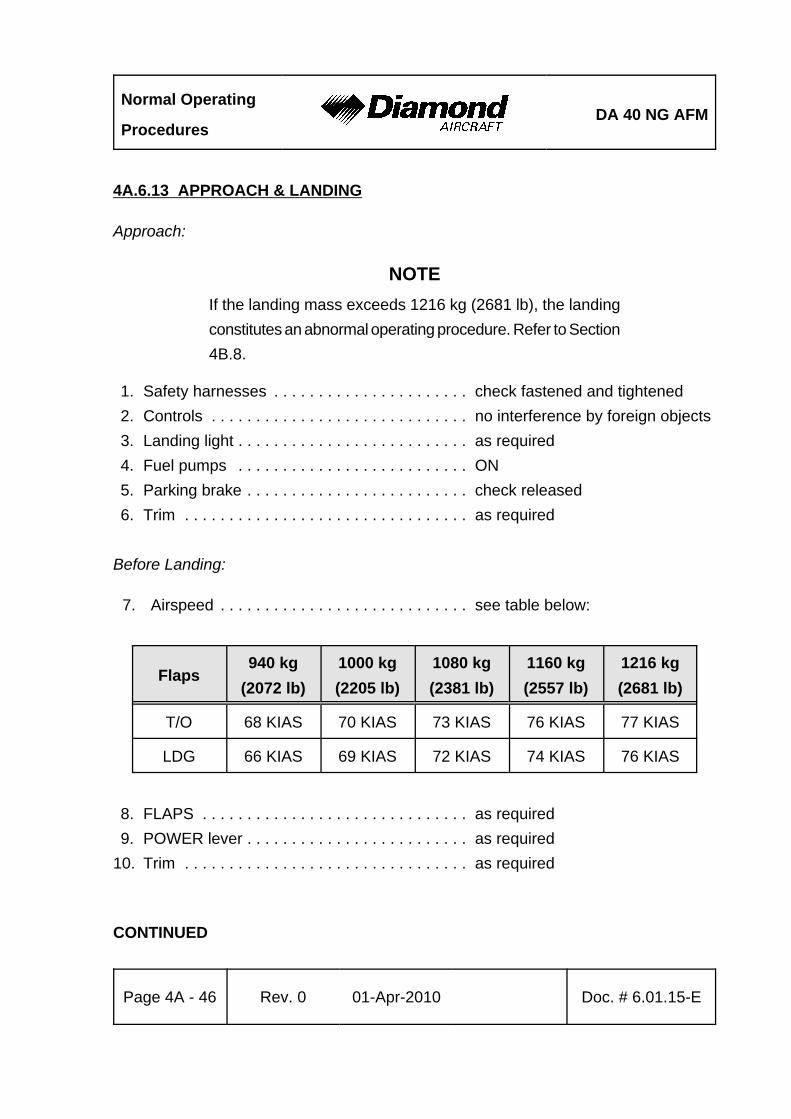
Normal Operating
ProceduresDA 40 NG AFM
Page 4A - 46 Rev. 0 01-Apr-2010 Doc. # 6.01.15-E
4A.6.13 APPROACH & LANDING
Approach:
NOTEIf the landing mass exceeds 1216 kg (2681 lb), the landingconstitutes an abnormal operating procedure. Refer to Section4B.8.
1. Safety harnesses . . . . . . . . . . . . . . . . . . . . . . check fastened and tightened2. Controls . . . . . . . . . . . . . . . . . . . . . . . . . . . . . no interference by foreign objects3. Landing light . . . . . . . . . . . . . . . . . . . . . . . . . . as required4. Fuel pumps . . . . . . . . . . . . . . . . . . . . . . . . . . ON5. Parking brake . . . . . . . . . . . . . . . . . . . . . . . . . check released6. Trim . . . . . . . . . . . . . . . . . . . . . . . . . . . . . . . . as required
Before Landing:
7. Airspeed . . . . . . . . . . . . . . . . . . . . . . . . . . . . see table below:
Flaps940 kg
(2072 lb)1000 kg(2205 lb)
1080 kg(2381 lb)
1160 kg(2557 lb)
1216 kg(2681 lb)
T/O 68 KIAS 70 KIAS 73 KIAS 76 KIAS 77 KIAS
LDG 66 KIAS 69 KIAS 72 KIAS 74 KIAS 76 KIAS
8. FLAPS . . . . . . . . . . . . . . . . . . . . . . . . . . . . . . as required9. POWER lever . . . . . . . . . . . . . . . . . . . . . . . . . as required
10. Trim . . . . . . . . . . . . . . . . . . . . . . . . . . . . . . . . as required
CONTINUED
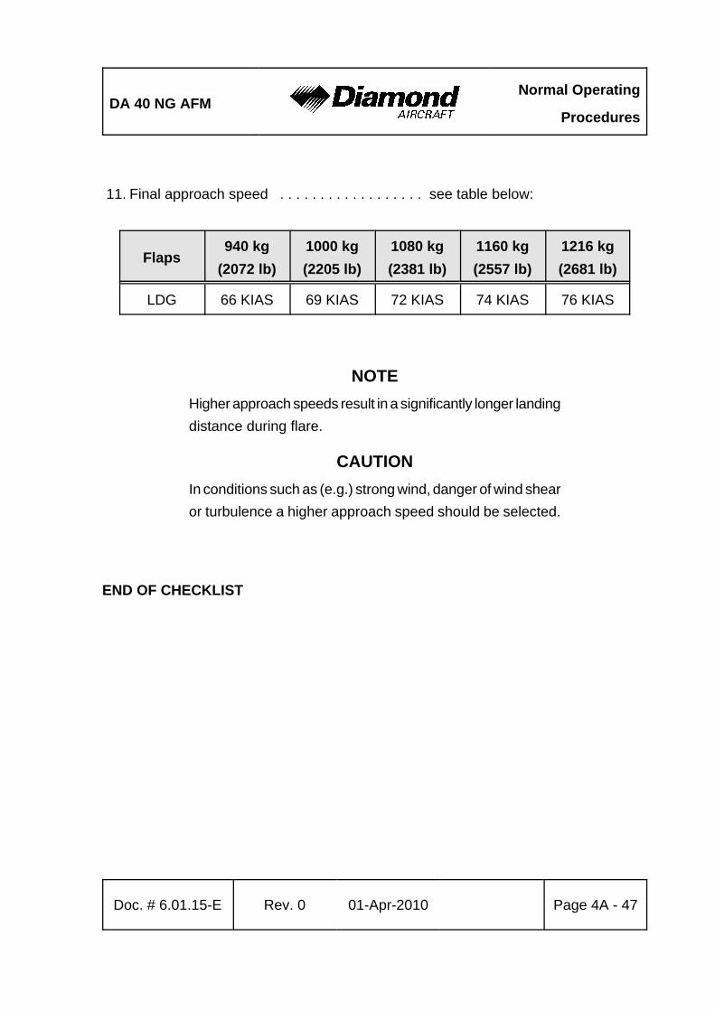
DA 40 NG AFMNormal Operating
Procedures
Doc. # 6.01.15-E Rev. 0 01-Apr-2010 Page 4A - 47
11. Final approach speed . . . . . . . . . . . . . . . . . . see table below:
Flaps940 kg
(2072 lb)1000 kg(2205 lb)
1080 kg(2381 lb)
1160 kg(2557 lb)
1216 kg(2681 lb)
LDG 66 KIAS 69 KIAS 72 KIAS 74 KIAS 76 KIAS
NOTEHigher approach speeds result in a significantly longer landingdistance during flare.
CAUTIONIn conditions such as (e.g.) strong wind, danger of wind shearor turbulence a higher approach speed should be selected.
END OF CHECKLIST
Normal Operating
ProceduresDA 40 NG AFM
Page 4A - 48 Rev. 0 01-Apr-2010 Doc. # 6.01.15-E
GFC700 Operation During Approach
a) VOR:
1. Navigation source . . . . . . . . . . . . . . . . . . . . . select VOR using CDI button on PFD
2. Course bearing pointer . . . . . . . . . . . . . . . . set using course knob 3. Intercept heading . . . . . . . . . . . . . . . . . . . . . establish in HDG or ROL
mode (if required) 4. Mode controller . . . . . . . . . . . . . . . . . . . . . . select APR on mode controller 5. Green or white VAPP annunciation . . . . . . . note on PFD 6. Vertical mode and reference . . . . . . . . . . . . select on mode controller
NOTEIf the Course Deviation Indicator (CDI) is greater than onedot from center, the autopilot will arm the VAPP mode andindicate VAPP in white on the PFD. The pilot must ensurethat the current heading will result in a capture of the selectedcourse. If the CDI is one dot or less from center, the autopilotwill enter the capture mode when the VAPP button is pressedand annunciate VAPP in green on the PFD.
END OF CHECKLIST
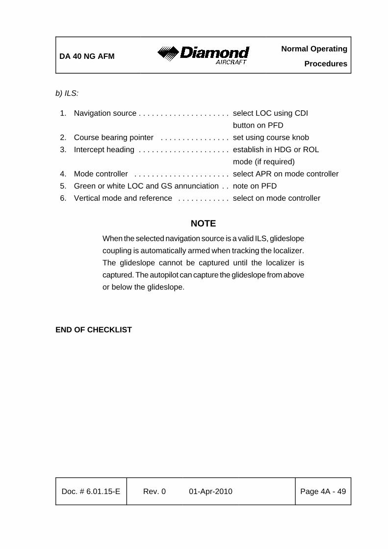
DA 40 NG AFMNormal Operating
Procedures
Doc. # 6.01.15-E Rev. 0 01-Apr-2010 Page 4A - 49
b) ILS:
1. Navigation source . . . . . . . . . . . . . . . . . . . . . select LOC using CDI button on PFD
2. Course bearing pointer . . . . . . . . . . . . . . . . set using course knob 3. Intercept heading . . . . . . . . . . . . . . . . . . . . . establish in HDG or ROL
mode (if required) 4. Mode controller . . . . . . . . . . . . . . . . . . . . . . select APR on mode controller5. Green or white LOC and GS annunciation . . note on PFD 6. Vertical mode and reference . . . . . . . . . . . . select on mode controller
NOTEWhen the selected navigation source is a valid ILS, glideslopecoupling is automatically armed when tracking the localizer.The glideslope cannot be captured until the localizer iscaptured. The autopilot can capture the glideslope from aboveor below the glideslope.
END OF CHECKLIST
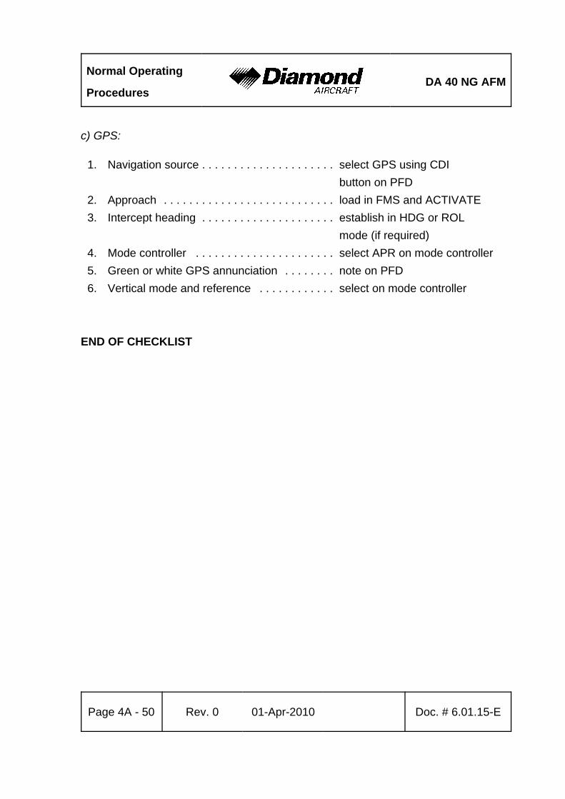
Normal Operating
ProceduresDA 40 NG AFM
Page 4A - 50 Rev. 0 01-Apr-2010 Doc. # 6.01.15-E
c) GPS:
1. Navigation source . . . . . . . . . . . . . . . . . . . . . select GPS using CDI button on PFD
2. Approach . . . . . . . . . . . . . . . . . . . . . . . . . . . load in FMS and ACTIVATE3. Intercept heading . . . . . . . . . . . . . . . . . . . . . establish in HDG or ROL
mode (if required) 4. Mode controller . . . . . . . . . . . . . . . . . . . . . . select APR on mode controller5. Green or white GPS annunciation . . . . . . . . note on PFD 6. Vertical mode and reference . . . . . . . . . . . . select on mode controller
END OF CHECKLIST
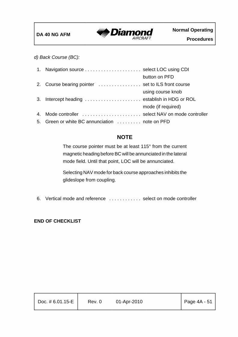
DA 40 NG AFMNormal Operating
Procedures
Doc. # 6.01.15-E Rev. 0 01-Apr-2010 Page 4A - 51
d) Back Course (BC):
1. Navigation source . . . . . . . . . . . . . . . . . . . . . select LOC using CDI button on PFD
2. Course bearing pointer . . . . . . . . . . . . . . . . set to ILS front course using course knob
3. Intercept heading . . . . . . . . . . . . . . . . . . . . . establish in HDG or ROL mode (if required)
4. Mode controller . . . . . . . . . . . . . . . . . . . . . . select NAV on mode controller5. Green or white BC annunciation . . . . . . . . . note on PFD
NOTEThe course pointer must be at least 115° from the currentmagnetic heading before BC will be annunciated in the lateralmode field. Until that point, LOC will be annunciated.
Selecting NAV mode for back course approaches inhibits theglideslope from coupling.
6. Vertical mode and reference . . . . . . . . . . . . select on mode controller
END OF CHECKLIST
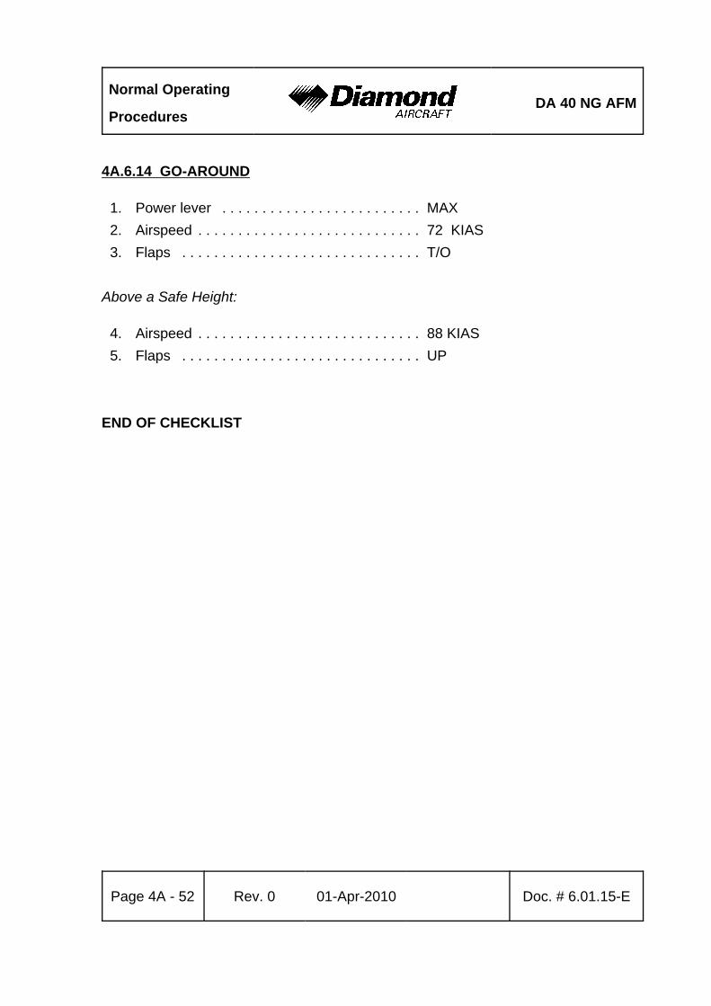
Normal Operating
ProceduresDA 40 NG AFM
Page 4A - 52 Rev. 0 01-Apr-2010 Doc. # 6.01.15-E
4A.6.14 GO-AROUND
1. Power lever . . . . . . . . . . . . . . . . . . . . . . . . . MAX2. Airspeed . . . . . . . . . . . . . . . . . . . . . . . . . . . . 72 KIAS3. Flaps . . . . . . . . . . . . . . . . . . . . . . . . . . . . . . T/O
Above a Safe Height:
4. Airspeed . . . . . . . . . . . . . . . . . . . . . . . . . . . . 88 KIAS5. Flaps . . . . . . . . . . . . . . . . . . . . . . . . . . . . . . UP
END OF CHECKLIST

DA 40 NG AFMNormal Operating
Procedures
Doc. # 6.01.15-E Rev. 0 01-Apr-2010 Page 4A - 53
GFC700 Operation During Go-Around
1. Control stick . . . . . . . . . . . . . . . . . . . . . . . . . GRASP FIRMLY2. GA button . . . . . . . . . . . . . . . . . . . . . . . . . . PUSH - Verify GA/GA on PFD
in lateral and vertical mode fields
NOTEAfter the GA button is pressed, the autopilot disconnects andthe flight director indicates a 7° pitch up attitude.
3. Balked landing . . . . . . . . . . . . . . . . . . . . . . . execute4. Missed approach procedure . . . . . . . . . . . . execute (as applicable)5. Altitude preselect . . . . . . . . . . . . . . . . . . . . . set to appropriate altitude
At an Appropriate Safe Altitude:
6. Autopilot mode controller . . . . . . . . . . . . . . . select appropriate lateraland vertical mode on controller
7. Autopilot . . . . . . . . . . . . . . . . . . . . . . . . . . . RE-ENGAGE if desired
NOTEIf the missed approach procedure requires tracking thelocalizer outbound from the airport, use NAV mode to preventinadvertent coupling to glideslope.
END OF CHECKLIST
Normal Operating
ProceduresDA 40 NG AFM
Page 4A - 54 Rev. 0 01-Apr-2010 Doc. # 6.01.15-E
4A.6.15 AFTER LANDING
1. Power lever . . . . . . . . . . . . . . . . . . . . . . . . . IDLE2. Brakes . . . . . . . . . . . . . . . . . . . . . . . . . . . . . as required3. Transponder . . . . . . . . . . . . . . . . . . . . . . . . . OFF / STBY4. Pitot heating . . . . . . . . . . . . . . . . . . . . . . . . . OFF5. Avionics . . . . . . . . . . . . . . . . . . . . . . . . . . . . as required6. Lights . . . . . . . . . . . . . . . . . . . . . . . . . . . . . . as required7. Flaps . . . . . . . . . . . . . . . . . . . . . . . . . . . . . . UP8. Fuel pumps . . . . . . . . . . . . . . . . . . . . . . . . . OFF
END OF CHECKLIST
DA 40 NG AFMNormal Operating
Procedures
Doc. # 6.01.15-E Rev. 0 01-Apr-2010 Page 4A - 55
4A.6.16 ENGINE SHUT-DOWN
1. Parking brake . . . . . . . . . . . . . . . . . . . . . . . . . set2. POWER lever . . . . . . . . . . . . . . . . . . . . . . . . . up to 10 % load for 1 minute3. Engine/System Page . . . . . . . . . . . . . . . . . . . check4. ELT . . . . . . . . . . . . . . . . . . . . . . . . . . . . . . . . check not transmitting on
121.5 MHz5. AVIONIC MASTER . . . . . . . . . . . . . . . . . . . . OFF6. Electrical consumers . . . . . . . . . . . . . . . . . . . OFF7. ENGINE MASTER . . . . . . . . . . . . . . . . . . . . . OFF8. Strobe . . . . . . . . . . . . . . . . . . . . . . . . . . . . . . OFF
CAUTIONAfter turning the ENGINE MASTER OFF, wait until the G1000engine indications are red X'd prior to switching theELECTRIC MASTER OFF. This ensures that engine and flightdata can be written to non-volatile memory before removingelectrical power.
9. ELECTRIC MASTER . . . . . . . . . . . . . . . . . . . OFF
CAUTIONDo not shut down an engine by placing the FUEL VALVE inthe OFF position. The high pressure fuel pump can otherwisebe damaged.
NOTEBefore shut-down the engine must run for at least 1 minutewith the power lever set up to 10% load to avoid heat damageof the turbo charger.
END OF CHECKLIST
Normal Operating
ProceduresDA 40 NG AFM
Page 4A - 56 Rev. 0 01-Apr-2010 Doc. # 6.01.15-E
4A.6.17 POST FLIGHT INSPECTION
1. Record any problem found in flight and during the post-flight check in the log book.2. Park the airplane.3. If necessary, moor the airplane.
END OF CHECKLIST
4A.6.18 PARKING
1. Parking brake . . . . . . . . . . . . . . . . . . . . . . . . . release, use chocks2. Airplane . . . . . . . . . . . . . . . . . . . . . . . . . . . . . moor, if unsupervised for
extended period3. Pitot probe . . . . . . . . . . . . . . . . . . . . . . . . . . . cover
END OF CHECKLIST

DA 40 NG AFMNormal Operating
Procedures
Doc. # 6.01.15-E Rev. 0 01-Apr-2010 Page 4A - 57
4A.6.19 FLIGHT IN RAIN
NOTEPerformance deteriorates in rain; this applies particularly tothe take-off distance and to the maximum horizontal speed.The effect on the flight characteristics is minimal. Flightthrough very heavy rain should be avoided because of theassociated visibility problems.
4A.6.20 REFUELING
CAUTIONBefore refueling, the airplane must be connected to electricalground. Grounding points: unpainted areas on steps, left andright.
4A.6.21 FLIGHT AT HIGH ALTITUDE
At high altitudes the provision of oxygen for the occupants is necessary. Legalrequirements for the provision of oxygen should be adhered to.
Also see Section 2.11 - OPERATING ALTITUDE.

Normal Operating
ProceduresDA 40 NG AFM
Page 4A - 58 Rev. 0 01-Apr-2010 Doc. # 6.01.15-E
Intentionally left blank.
DA 40 NG AFMAbnormal Operating
Procedures
Doc. # 6.01.15-E Rev. 0 01-Apr-2010 Page 4B - 1
CHAPTER 4BABNORMAL OPERATING PROCEDURES
Page4B.1 PRECAUTIONARY LANDING . . . . . . . . . . . . . . . . . . . . . . . . . . . . 4B-34B.2 CANOPY IN COOLING GAP POSITION . . . . . . . . . . . . . . . . . . . 4B-44B.3 ENGINE INSTRUMENT INDICATIONS OUTSIDE OF GREEN RANGE ON
THE G1000 . . . . . . . . . . . . . . . . . . . . . . . . . . . . . . . . . . . . . . . . . . 4B-54B.3.1 RPM . . . . . . . . . . . . . . . . . . . . . . . . . . . . . . . . . . . . . . . . . 4B-54B.3.2 COOLANT TEMPERATURE . . . . . . . . . . . . . . . . . . . . . . . 4B-64B.3.3 OIL TEMPERATURE . . . . . . . . . . . . . . . . . . . . . . . . . . . . 4B-74B.3.4 OIL PRESSURE . . . . . . . . . . . . . . . . . . . . . . . . . . . . . . . . 4B-84B.3.5 GEARBOX TEMPERATURE . . . . . . . . . . . . . . . . . . . . . . 4B-94B.3.6 FUEL TEMPERATURE . . . . . . . . . . . . . . . . . . . . . . . . . . 4B-104B.3.7 VOLTAGE . . . . . . . . . . . . . . . . . . . . . . . . . . . . . . . . . . . . 4B-11
4B.4 CAUTION-ALERTS ON THE G1000 . . . . . . . . . . . . . . . . . . . . . . 4B-124B.4.1 CAUTIONS / GENERAL . . . . . . . . . . . . . . . . . . . . . . . . . 4B-124B.4.2 ECU A FAIL . . . . . . . . . . . . . . . . . . . . . . . . . . . . . . . . . . 4B-124B.4.3 ECU B FAIL . . . . . . . . . . . . . . . . . . . . . . . . . . . . . . . . . . 4B-134B.4.4 FUEL LOW . . . . . . . . . . . . . . . . . . . . . . . . . . . . . . . . . . . 4B-144B.4.5 LOW VOLTAGE CAUTION (LOW VOLTS) . . . . . . . . . . 4B-154B.4.6 COOL LVL . . . . . . . . . . . . . . . . . . . . . . . . . . . . . . . . . . . 4B-164B.4.7 PITOT FAIL / HT OFF . . . . . . . . . . . . . . . . . . . . . . . . . . . 4B-174B.4.8 LOI . . . . . . . . . . . . . . . . . . . . . . . . . . . . . . . . . . . . . . . . . . 4B-184B.4.9 AHRS ALIGNING - KEEP WINGS LEVEL . . . . . . . . . . . 4B-19
4B.5 FAILURES IN FLAP OPERATING SYSTEM . . . . . . . . . . . . . . . 4B-20
Abnormal Operating
ProceduresDA 40 NG AFM
Page 4B - 2 Rev. 0 01-Apr-2010 Doc. # 6.01.15-E
4B.6 FAILURES IN THE AUTOPILOT SYSTEM . . . . . . . . . . . . . . . . . 4B-224B.6.1 AUTOPILOT DISCONNECT (yellow AP flashing on PFD)
. . . . . . . . . . . . . . . . . . . . . . . . . . . . . . . . . . . . . . . . . . . . . 4B-224B.6.2 AUTOPILOT OVERSPEED RECOVERY (yellow MAXSPD on PFD)
. . . . . . . . . . . . . . . . . . . . . . . . . . . . . . . . . . . . . . . . . . . . . 4B-234B.6.3 LOSS OF NAVIGATION INFORMATION (Yellow VOR, VAPP, GPS
or LOC flashing on PFD) . . . . . . . . . . . . . . . . . . . . . . . . . 4B-244B.6.4 AUTOPILOT OUT OF TRIM (Yellow 7AIL, 6AIL, 8ELE, 9ELE on
PFD) . . . . . . . . . . . . . . . . . . . . . . . . . . . . . . . . . . . . . . . . . 4B-254B.6.5 FLASHING YELLOW MODE ANNUNCIATION . . . . . . . 4B-284B.6.6 EFFECTS OF G1000 LOSSES UPON AUTOPILOT OPERATION
. . . . . . . . . . . . . . . . . . . . . . . . . . . . . . . . . . . . . . . . . . . . . 4B-294B.7 LIGHTNING STRIKE . . . . . . . . . . . . . . . . . . . . . . . . . . . . . . . . . . 4B-304B.8 LANDING WITH HIGH LANDING MASS . . . . . . . . . . . . . . . . . . 4B-31
DA 40 NG AFMAbnormal Operating
Procedures
Doc. # 6.01.15-E Rev. 0 01-Apr-2010 Page 4B - 3
4B.1 PRECAUTIONARY LANDING
NOTEA landing of this type is only necessary when there is areasonable suspicion that due to operational factors such asfuel shortage, weather conditions, etc. the possibility ofendangering the airplane and its occupants by continuing theflight cannot be excluded. The pilot is required to decidewhether or not a controlled landing in a field represents alower risk than the attempt to reach the nearest airfield underall circumstances.
NOTEIf no level landing area is available, a landing on an upwardslope should be sought.
1. Select appropriate landing area.2. Consider wind.3. Approach:
If possible, the landing area should be overflown at a suitable height in order torecognize obstacles. The degree of offset at each part of the circuit will allow thewind speed and direction to be assessed.
4. ATC . . . . . . . . . . . . . . . . . . . . . . . . . . . . . . . advise
Perform procedures according to Normal Procedures 4A.6.13 - APPROACH & LANDING.
5. Touchdown . . . . . . . . . . . . . . . . . . . . . . . . . . with the lowest possible airspeed
CONTINUED
Abnormal Operating
ProceduresDA 40 NG AFM
Page 4B - 4 Rev. 0 01-Apr-2010 Doc. # 6.01.15-E
CAUTIONIf sufficient time is remaining, the risk of fire in the event ofa collision with obstacles can be reduced as follows after asafe touch-down:
6. ENGINE MASTER . . . . . . . . . . . . . . . . . . OFF7. Fuel valve . . . . . . . . . . . . . . . . . . . . . . . . . OFF8. ELECTRIC MASTER . . . . . . . . . . . . . . . . OFF
END OF CHECKLIST
4B.2 CANOPY IN COOLING GAP POSITION
CAUTIONIf take-off was inadvertently done with the canopy in thecooling gap position, do not attempt to close the canopy inflight. Land the airplane and close the canopy on ground.
DA 40 NG AFMAbnormal Operating
Procedures
Doc. # 6.01.15-E Rev. 0 01-Apr-2010 Page 4B - 5
4B.3 ENGINE INSTRUMENT INDICATIONS OUTSIDE OF GREENRANGE ON THE G1000
4B.3.1 RPM
High RPM
1. Reduce power.2. Keep RPM within the green range using the power lever.
NOTE An RPM in the yellow range is permissible for up to 5 minutesif required, e.g. for go-around or take-off.
If the above mentioned measures do not solve the problem refer to Section3.5.6 - DEFECTIVE RPM REGULATING SYSTEM.
3. Land at the nearest suitable airfield.
END OF CHECKLIST
Abnormal Operating
ProceduresDA 40 NG AFM
Page 4B - 6 Rev. 0 01-Apr-2010 Doc. # 6.01.15-E
4B.3.2 COOLANT TEMPERATURE
(a) High Coolant Temperature
Proceed according to:
3.2.2 - ENG TEMP
(b) Low Coolant Temperature
- Check G1000 for COOL LVL caution message (low coolant level).
NOTEDuring an extended descent from high altitudes with a lowpower setting coolant temperature may decrease. In this casean increase in power and a decrease in airspeed can help.
COOL LVL Caution Message Displayed:
- Reduce power.- Expect loss of coolant.
WARNINGA further decrease in coolant temperature must be expected.Prepare for an engine failure in accordance with3.5.3 - ENGINE TROUBLESHOOTING IN FLIGHT.
END OF CHECKLIST
DA 40 NG AFMAbnormal Operating
Procedures
Doc. # 6.01.15-E Rev. 0 01-Apr-2010 Page 4B - 7
4B.3.3 OIL TEMPERATURE
a) High Oil Temperature
Proceed according to:
3.2.3 - OIL TEMP
(b) Low Oil Temperature
NOTEDuring an extended descent from high altitudes with a lowpower setting oil temperature may decrease. In this case anincrease in power can help.
- Increase power.- Reduce airspeed.
END OF CHECKLIST
Abnormal Operating
ProceduresDA 40 NG AFM
Page 4B - 8 Rev. 0 01-Apr-2010 Doc. # 6.01.15-E
4B.3.4 OIL PRESSURE
(a) High Oil Pressure
- Check oil temperature.- Check coolant temperature.
If the Temperatures are Within the Green Range:
- Expect false oil pressure indication. Keep monitoring temperatures.
If the Temperatures are Outside of the Green Range:
- Reduce power.
WARNINGLand at the nearest suitable airfield. Prepare for an enginefailure in accordance with 3.5.4 - ENGINE FAILURE INFLIGHT.
(b) Low Oil Pressure
Proceed according to:
3.2.4 - OIL PRES
END OF CHECKLIST
DA 40 NG AFMAbnormal Operating
Procedures
Doc. # 6.01.15-E Rev. 0 01-Apr-2010 Page 4B - 9
4B.3.5 GEARBOX TEMPERATURE
High Gearbox Temperature
Proceed according to:
3.2.5 - GBOX TEMP
NOTEA cautionary (yellow) gearbox temperature range is notimposed by the engine manufacturer. However, there is adelay between power changes and gearbox temperature.Therefore, a cautionary range has been added to the G1000gearbox temperature instrument solely to make the pilotattentive to the gearbox temperature approaching themaximum allowable limit. There is no specific time limitassociated with operating in the cautionary gearboxtemperature range.
END OF CHECKLIST
Abnormal Operating
ProceduresDA 40 NG AFM
Page 4B - 10 Rev. 0 01-Apr-2010 Doc. # 6.01.15-E
4B.3.6 FUEL TEMPERATURE
(a) High Fuel Temperature
Proceed according to:
3.2.6 - FUEL TEMP
(b) Low Fuel Temperature
- Increase power.- Reduce airspeed.
CAUTIONAt low ambient temperature conditions and/or at highairspeeds with low power settings, it can be assumed thatthe above mentioned procedure will increase thetemperature(s). If the fuel temperature does not return to thegreen range perform a precautionary landing on the nearestsuitable airfield. Prepare for an engine failure in accordancewith 3.5.4 - ENGINE FAILURE IN FLIGHT.
END OF CHECKLIST
DA 40 NG AFMAbnormal Operating
Procedures
Doc. # 6.01.15-E Rev. 0 01-Apr-2010 Page 4B - 11
4B.3.7 VOLTAGE
(a) Low Voltage Indication on the Ground with Engine Running
- Terminate flight preparation.
(b) Low Voltage During Flight
1. Circuit breakers . . . . . . . . . . . . . . . . . . . . . . check2. Electrical equipment . . . . . . . . . . . . . . . . . . . OFF if not needed
If LOW VOLTAGE CAUTION (4B.4.5 - LOW VOLTS) Is Still Indicated on the G1000:
- Follow procedure in 3.2.9 - ALTN FAIL.
END OF CHECKLIST
Abnormal Operating
ProceduresDA 40 NG AFM
Page 4B - 12 Rev. 0 01-Apr-2010 Doc. # 6.01.15-E
4B.4 CAUTION-ALERTS ON THE G1000
The G1000 provides the following CAUTION-alerts on the PFD in the ALERT area.
4B.4.1 CAUTIONS / GENERAL
CHARACTERISTICS * Yellow color coded text.
* Single warning chime tone of 1.5 seconds duration.
4B.4.2 ECU A FAIL
ECU A FAIL * Engine ECU A has failed
or
* is being tested during FADEC test procedure beforetake-off check.
(a) ECU A Caution on the Ground
- Terminate flight preparation.
(b) ECU A Caution During Flight
NOTEIn case of a failure in the electronic ECU (Engine Control Unit)'A' the system automatically switches to ECU 'B'.
1. VOTER switch . . . . . . . . . . . . . . . . . . . . . . . check AUTO2. If the ECU caution remains . . . . . . . . . . . . . land at the next suitable airfield
NOTEIf additional engine problems are observed refer to 3.5.3 -ENGINE TROUBLESHOOTING IN FLIGHT.
END OF CHECKLIST
DA 40 NG AFMAbnormal Operating
Procedures
Doc. # 6.01.15-E Rev. 0 01-Apr-2010 Page 4B - 13
4B.4.3 ECU B FAIL
ECU B FAIL * Engine ECU B has failed
or
* is being tested during FADEC test procedure beforetake-off check.
(a) ECU B Caution on the Ground
- Terminate flight preparation.
(b) ECU B Caution During Flight
NOTEIn case of a failure in the electronic ECU (Engine Control Unit)'B' the system automatically switches to ECU 'A'.
1. VOTER switch . . . . . . . . . . . . . . . . . . . . . . . check AUTO2. If the ECU caution remains . . . . . . . . . . . . . land at the next suitable airfield
NOTEIf additional engine problems are observed refer to 3.5.3 -ENGINE TROUBLESHOOTING IN FLIGHT.
END OF CHECKLIST
Abnormal Operating
ProceduresDA 40 NG AFM
Page 4B - 14 Rev. 0 01-Apr-2010 Doc. # 6.01.15-E
4B.4.4 FUEL LOW
FUEL LOW Left fuel quantity is low.
1. Fuel transfer pump . . . . . . . . . . . . . . . . . . . . ON2. Fuel quantity . . . . . . . . . . . . . . . . . . . . . . . . . check
CAUTIONAs soon as the amount of usable fuel in the main tank is low,a caution message is displayed. The indication is calibratedfor straight and level flight. The caution message may betriggered during turns which are flown with slip, or whiletaxiing in curves.
If FUEL LOW Caution Is Caused By Un-Coordinated Flight:
CAUTIONProlonged un-coordinated flight can cause fuel starvation tothe engine resulting in a loss of power.
3. Return to coordinated flight (not more than approx. half a ball sideslip, 3°-5° bank)
If the Caution Does Not Extinguish:
- Expect loss of fuel.
4. Fuel valve . . . . . . . . . . . . . . . . . . . . . . . . . . . EMERGENCY5. Fuel transfer pump . . . . . . . . . . . . . . . . . . . . OFF
CONTINUED
DA 40 NG AFMAbnormal Operating
Procedures
Doc. # 6.01.15-E Rev. 0 01-Apr-2010 Page 4B - 15
If the Caution Does Not Extinguish:
- Be prepared for an emergency landing.- Proceed in accordance with 3.9.1 - EMERGENCY LANDING WITH ENGINE OFF.
WARNING If air enters the high pressure fuel pump (e.g. empty fueltank), an inspection of the pump is necessary prior to nextflight.
END OF CHECKLIST
4B.4.5 LOW VOLTAGE CAUTION (LOW VOLTS)
VOLTS LOW Bus voltage is too low (less than 25 volts).
Possible reasons are:
- A fault in the power supply.
Continue with 4B.3.7 - VOLTAGE.
END OF CHECKLIST
Abnormal Operating
ProceduresDA 40 NG AFM
Page 4B - 16 Rev. 0 01-Apr-2010 Doc. # 6.01.15-E
4B.4.6 COOL LVL
COOL LVL Engine coolant level is low.
A low coolant caution alert may indicate a loss of coolant. This will subsequently lead todecreased engine cooling capability/loss of engine power due to engine failure.
1. Annunciations / engine instruments . . . . . . . monitor
Refer to 4B.3.2 - COOLANT TEMPERATURE.
NOTEThe indication is calibrated for straight and level flight. Thecaution message may be triggered during turns which areflown with slip, or while taxiing in curves.
END OF CHECKLIST
DA 40 NG AFMAbnormal Operating
Procedures
Doc. # 6.01.15-E Rev. 0 01-Apr-2010 Page 4B - 17
4B.4.7 PITOT FAIL / HT OFF
PITOT FAIL Pitot heating system has failed.
PITOT HT OFF Pitot heating system is OFF.
1. PITOT HEAT . . . . . . . . . . . . . . . . . . . . . . . . check ON / as required
NOTEThe Pitot heating caution message is displayed when the Pitotheating is switched OFF, or when there is a failure of the Pitotheating system. Prolonged operation of the Pitot heating onthe ground can also cause the Pitot heating caution messageto be displayed. In this case it indicates the activation of thethermal switch, which prevents overheating of the Pitotheating system on the ground. This is a normal function ofthe system. After a cooling period, the heating system will beswitched on again automatically.
If in Icing Conditions:
2. Expect loss of airspeed indication.3. Leave icing zone / refer to 3.11.1 - ICING.
END OF CHECKLIST
Abnormal Operating
ProceduresDA 40 NG AFM
Page 4B - 18 Rev. 0 01-Apr-2010 Doc. # 6.01.15-E
4B.4.8 LOI
LOI GPS integrity is insufficient for the current phase of flight.
(a) Enroute, Oceanic, Terminal, or Initial Approach Phase of Flight
If the LOI annunciation is displayed in the enroute, oceanic, terminal, or initial approachphase of flight, continue to navigate using the GPS equipment or revert to an alternatemeans of navigation other than the G1000 GPS receiver appropriate to the route andphase of flight. When continuing to use GPS navigation, position must be verified every15 minutes using the G1000 VOR/ILS receiver or another IFR-approved navigation system.
(b) Final Approach
If the LOI annunciation is displayed while on the final approach segment, GPS basednavigation will be aborted.
END OF CHECKLIST
DA 40 NG AFMAbnormal Operating
Procedures
Doc. # 6.01.15-E Rev. 0 01-Apr-2010 Page 4B - 19
4B.4.9 AHRS ALIGNING - KEEP WINGS LEVEL
AHRS ALIGN:Keep WingsLevel
The AHRS (Attitude and Heading Reference System) isaligning.
Keep wings level using standby attitude indicator.
END OF CHECKLIST
Abnormal Operating
ProceduresDA 40 NG AFM
Page 4B - 20 Rev. 0 01-Apr-2010 Doc. # 6.01.15-E
4B.5 FAILURES IN FLAP OPERATING SYSTEM
Failure in Position Indication or Function
1. FLAPS position . . . . . . . . . . . . . . . . . . . . . . . check visually2. Airspeed . . . . . . . . . . . . . . . . . . . . . . . . . . . . keep in white range
(max. 98 KIAS)3. FLAPS switch . . . . . . . . . . . . . . . . . . . . . . . . re-check all positions
Modified Approach Procedure Depending on the Available Flap Setting
NOTEFor landing distances with an abnormal flap position refer to5.3.12 - LANDING DISTANCE - ABNORMAL FLAPPOSITION.
(a) Only UP Available:
Airspeed . . . . . . . . . . . . . . . . . . . . . . . . . . . . see table below:
940 kg(2072 lb)
1000 kg(2205 lb)
1080 kg(2381 lb)
1160 kg(2557 lb)
1216 kg(2681 lb)
up to1280 kg(2822 lb)
71 KIAS 73 KIAS 78 KIAS 81 KIAS 82 KIAS 83 KIAS
NOTEIf the landing mass exceeds 1216 kg (2681 lb), the landingconstitutes an abnormal operating procedure. Refer to Section4B.8 - LANDING WITH HIGH LANDING MASS.
Land at a flat approach angle, use power lever to control airplane speed and rateof descent.
CONTINUED
DA 40 NG AFMAbnormal Operating
Procedures
Doc. # 6.01.15-E Rev. 0 01-Apr-2010 Page 4B - 21
(b) Only T/O Available:
Airspeed . . . . . . . . . . . . . . . . . . . . . . . . . . . . see table below:
940 kg(2072 lb)
1000 kg(2205 lb)
1080 kg(2381 lb)
1160 kg(2557 lb)
1216 kg(2681 lb)
up to1280 kg(2822 lb)
68 KIAS 70 KIAS 73 KIAS 76 KIAS 77 KIAS 78 KIAS
NOTEIf the landing mass exceeds 1216 kg (2681 lb), the landingconstitutes an abnormal operating procedure. Refer to Section4B.8 - LANDING WITH HIGH LANDING MASS.
Land at a flat approach angle, use power lever to control airplane speed and rate ofdescent.
(c) Only LDG Available:
Perform normal landing.
END OF CHECKLIST
Abnormal Operating
ProceduresDA 40 NG AFM
Page 4B - 22 Rev. 0 01-Apr-2010 Doc. # 6.01.15-E
4B.6 FAILURES IN THE AUTOPILOT SYSTEM
4B.6.1 AUTOPILOT DISCONNECT (yellow AP flashing on PFD)
1. AP DISC switch . . . . . . . . . . . . . . . . . . . . DEPRESS AND RELEASE (to cancel disconnect tone)
2. Pitch trim . . . . . . . . . . . . . . . . . . . . . . . . . retrim if necessary, using the trim wheel
NOTEThe autopilot disconnect may be accompanied by a red boxedPTCH (pitch) or ROLL on the PFD, indicating the axis whichhas failed. The autopilot cannot be re-engaged with eitherof these annunciations present.
END OF CHECKLIST
DA 40 NG AFMAbnormal Operating
Procedures
Doc. # 6.01.15-E Rev. 0 01-Apr-2010 Page 4B - 23
4B.6.2 AUTOPILOT OVERSPEED RECOVERY (yellow MAXSPD on PFD)
1. Power lever . . . . . . . . . . . . . . . . . . . . . . . . . reduce power
When Overspeed Condition is Corrected:
2. Autopilot . . . . . . . . . . . . . . . . . . . . . . . . . . . . reselect VERTICAL MODE (if necessary)
NOTEOverspeed recovery mode provides a pitch up command todecelerate the airplane at or below the maximum autopilotoperating speed (165 KIAS). Overspeed recovery is not activein altitude hold (ALT) or glideslope (GS) modes.
END OF CHECKLIST
Abnormal Operating
ProceduresDA 40 NG AFM
Page 4B - 24 Rev. 0 01-Apr-2010 Doc. # 6.01.15-E
4B.6.3 LOSS OF NAVIGATION INFORMATION (Yellow VOR, VAPP, GPS or LOCflashing on PFD)
NOTEIf a navigation signal is lost while the autopilot is tracking it,the autopilot will roll the airplane wings level and default toroll mode (ROL).
1. Autopilot . . . . . . . . . . . . . . . . . . . . . . . . . . select HDG on mode controller2. Nav source . . . . . . . . . . . . . . . . . . . . . . . . select a valid NAV source3. Autopilot . . . . . . . . . . . . . . . . . . . . . . . . . . select NAV on mode controller
If on an Instrument Approach at the Time the Navigation Signal Is Lost:
4. Missed approach procedure . . . . . . . . . . . EXECUTE (as applicable)
END OF CHECKLIST
DA 40 NG AFMAbnormal Operating
Procedures
Doc. # 6.01.15-E Rev. 0 01-Apr-2010 Page 4B - 25
4B.6.4 AUTOPILOT OUT OF TRIM (Yellow 7AIL, 6AIL, 8ELE, 9ELE on PFD)
For 8ELE, or 9ELE Indication:
WARNINGDo not attempt to overpower the autopilot in the event of apitch mistrim. The autopilot servos will oppose pilot input andwill cause pitch trim to run opposite the direction of pilot input.This will lead to a significant out-of-trim condition resultingin large control stick force when disengaging the autopilot.
CAUTIONBe prepared for significant sustained control forces in thedirection of the annunciation arrow. For example, an arrowpointing down indicates nose down control stick force will berequired upon autopilot disconnect.
NOTEMomentary illumination (5 sec or less) of the 8ELE, or 9ELEindication during configuration or large airspeed changes isnormal.
If the Annunciation Remains:
1. AP DISC switch . . . . . . . . . . . . . . . . . . . . DEPRESS AND HOLDwhile grasping control stick firmly
2. Airplane attitude . . . . . . . . . . . . . . . . . . . . maintain/regain airplane controluse standby attitude indicator if necessary
CONTINUED
Abnormal Operating
ProceduresDA 40 NG AFM
Page 4B - 26 Rev. 0 01-Apr-2010 Doc. # 6.01.15-E
3. Pitch trim . . . . . . . . . . . . . . . . . . . . . . . . . retrim if necessary, using the trim wheel
4. AUTOPILOT circuit breaker . . . . . . . . . . . PULL5. AP DISC switch . . . . . . . . . . . . . . . . . . . . RELEASE
WARNINGFollowing an autopilot, autotrim or manual electric trim systemmalfunction, do not engage the autopilot or operate themanual electric trim until the cause of the malfunction hasbeen corrected.
END OF CHECKLIST
DA 40 NG AFMAbnormal Operating
Procedures
Doc. # 6.01.15-E Rev. 0 01-Apr-2010 Page 4B - 27
For 7AIL, AIL6 Indication:
1. Rudder trim . . . . . . . . . . . . . . . . . . . . . . . Center slip/skid indicator
NOTEObserve the maximum fuel imbalance limitation.
If Annunciation Remains:
2. Control stick . . . . . . . . . . . . . . . . . . . . . . . GRASP FIRMLY with both hands
CAUTIONBe prepared for sustained control forces in the direction ofthe annunciation arrow. For example, an 7AIL indicates thatsustained right wing down control stick force will be requiredupon autopilot disconnect.
3. AP DISC switch . . . . . . . . . . . . . . . . . . . . DEPRESS4. Autopilot . . . . . . . . . . . . . . . . . . . . . . . . . . RE-ENGAGE if lateral trim is
re-established
END OF CHECKLIST

Abnormal Operating
ProceduresDA 40 NG AFM
Page 4B - 28 Rev. 0 01-Apr-2010 Doc. # 6.01.15-E
4B.6.5 FLASHING YELLOW MODE ANNUNCIATION
NOTEAbnormal mode transitions (those not initiated by the pilot orby normal sequencing of the autopilot) will be annunciatedby flashing the disengaged mode in yellow on the PFD. Uponloss of a selected mode, the system will revert to the defaultmode for the affected axis, either ROL or PIT. After 10seconds, the new mode (PIT or ROL) will be annunciated ingreen.
Loss of Selected Vertical Mode (FLC, VS, ALT, GS)
1. Autopilot mode controls . . . . . . . . . . . . . . select another vertical mode
If on an Instrument Approach:
2. Autopilot . . . . . . . . . . . . . . . . . . . . . . . . . . DISCONNECT and continuemanually or execute missed approach
END OF CHECKLIST
Loss of Selected Lateral Mode (HDG, NAV, GPS, LOC, VAPP, BC):
1. Autopilot mode controls . . . . . . . . . . . . . . select another lateral mode
If on an Instrument Approach:
2. Autopilot . . . . . . . . . . . . . . . . . . . . . . . . . . DISCONNECT and continue manually or execute missedapproach
END OF CHECKLIST
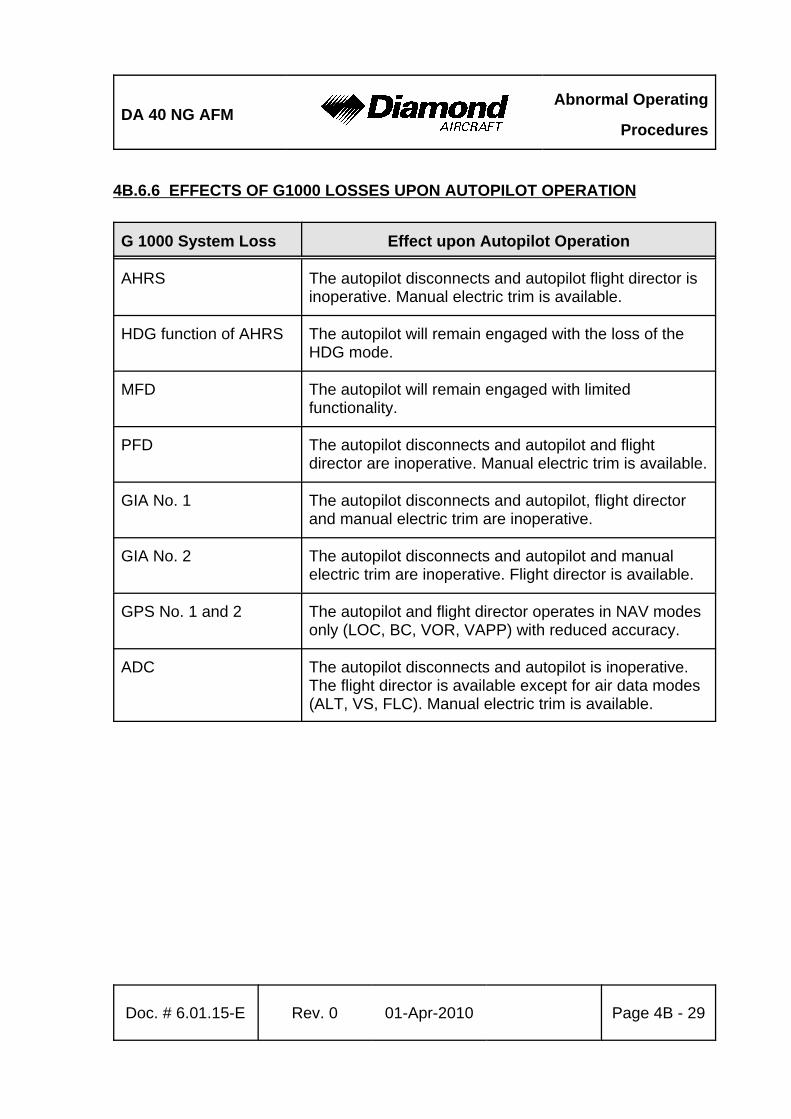
DA 40 NG AFMAbnormal Operating
Procedures
Doc. # 6.01.15-E Rev. 0 01-Apr-2010 Page 4B - 29
4B.6.6 EFFECTS OF G1000 LOSSES UPON AUTOPILOT OPERATION
G 1000 System Loss Effect upon Autopilot Operation
AHRS The autopilot disconnects and autopilot flight director isinoperative. Manual electric trim is available.
HDG function of AHRS The autopilot will remain engaged with the loss of theHDG mode.
MFD The autopilot will remain engaged with limitedfunctionality.
PFD The autopilot disconnects and autopilot and flightdirector are inoperative. Manual electric trim is available.
GIA No. 1 The autopilot disconnects and autopilot, flight directorand manual electric trim are inoperative.
GIA No. 2 The autopilot disconnects and autopilot and manualelectric trim are inoperative. Flight director is available.
GPS No. 1 and 2 The autopilot and flight director operates in NAV modesonly (LOC, BC, VOR, VAPP) with reduced accuracy.
ADC The autopilot disconnects and autopilot is inoperative.The flight director is available except for air data modes(ALT, VS, FLC). Manual electric trim is available.
Abnormal Operating
ProceduresDA 40 NG AFM
Page 4B - 30 Rev. 0 01-Apr-2010 Doc. # 6.01.15-E
4B.7 LIGHTNING STRIKE
1. Airspeed . . . . . . . . . . . . . . . . . . . . . . . . . . as low as practicable, do not exceed vO (refer to Section 2.2)
2. Grasp airplane controls firmly3. Autopilot . . . . . . . . . . . . . . . . . . . . . . . . . . disengage (check)4. PFD / backup instruments . . . . . . . . . . . . verify periodically5. Continue flight below vO (refer to Section 2.2)6. Land on the next suitable airfield
CAUTIONDue to possible damage to the airplane obey the followinginstructions:
- Avoid abrupt or full control surface movements.
- Avoid high g-loads on the airframe.
- Avoid high yaw angles.
- Avoid turbulent air as far as possible (e.g. lee effects).
- Do not fly into areas of known or forecast icing.
END OF CHECKLIST

DA 40 NG AFMAbnormal Operating
Procedures
Doc. # 6.01.15-E Rev. 0 01-Apr-2010 Page 4B - 31
4B.8 LANDING WITH HIGH LANDING MASS
NOTEThe maximum landing mass given in Chapter 2 is the highestmass for landing conditions at the maximum descent velocity.This velocity was used in the strength calculations todetermine the landing gear loads during a particularly hardlanding.
Perform landing approach and landing according to Chapter 4A, but maintain an increasedairspeed during landing approach.
Approach speed . . . . . . . . . . . . . . . . . . . . . . . . . . 77 KIAS up to 1280 kg (2822 lb),Flaps LDG
WARNINGDamage of the landing gear can result from a hard landingwith a flight mass above the maximum landing mass.
END OF CHECKLIST
Abnormal Operating
ProceduresDA 40 NG AFM
Page 4B - 32 Rev. 0 01-Apr-2010 Doc. # 6.01.15-E
Intentionally left blank.
DA 40 NG AFM Performance
Doc. # 6.01.15-E Rev. 0 01-Apr-2010 Page 5 - 1
CHAPTER 5PERFORMANCE
Page
5.1 INTRODUCTION . . . . . . . . . . . . . . . . . . . . . . . . . . . . . . . . . . . . . . . 5-25.2 USE OF THE PERFORMANCE TABLES AND DIAGRAMS . . . . . . 5-25.3 PERFORMANCE TABLES AND DIAGRAMS . . . . . . . . . . . . . . . . . 5-3
5.3.1 AIRSPEED CALIBRATION . . . . . . . . . . . . . . . . . . . . . . . . . . 5-35.3.2 FUEL FLOW DIAGRAM . . . . . . . . . . . . . . . . . . . . . . . . . . . . 5-65.3.3 PRESSURE ALTITUDE - DENSITY ALTITUDE . . . . . . . . . . 5-75.3.4 INTERNATIONAL STANDARD ATMOSPHERE . . . . . . . . . . 5-85.3.5 STALLING SPEEDS . . . . . . . . . . . . . . . . . . . . . . . . . . . . . . . 5-95.3.6 WIND COMPONENTS . . . . . . . . . . . . . . . . . . . . . . . . . . . . 5-115.3.7 TAKE-OFF DISTANCE . . . . . . . . . . . . . . . . . . . . . . . . . . . . 5-125.3.8 CLIMB PERFORMANCE - TAKE-OFF CLIMB . . . . . . . . . . 5-165.3.9 CLIMB PERFORMANCE - CRUISE CLIMB . . . . . . . . . . . . 5-185.3.10 CRUISING (TRUE AIRSPEED TAS) . . . . . . . . . . . . . . . . . 5-205.3.11 LANDING DISTANCE - FLAPS LDG . . . . . . . . . . . . . . . . 5-215.3.12 LANDING DISTANCE - ABNORMAL FLAP POSITION . . 5-245.3.13 GRADIENT OF CLIMB ON GO-AROUND . . . . . . . . . . . . 5-275.3.14 GLIDE . . . . . . . . . . . . . . . . . . . . . . . . . . . . . . . . . . . . . . . . 5-285.3.15 APPROVED NOISE DATA . . . . . . . . . . . . . . . . . . . . . . . . 5-29
Performance DA 40 NG AFM
Page 5 - 2 Rev. 0 01-Apr-2010 Doc. # 6.01.15-E
5.1 INTRODUCTION
The performance tables and diagrams on the following pages are presented so that, onthe one hand, you can see what performance you can expect from your airplane, whileon the other they allow comprehensive and sufficiently accurate flight planning. The valuesin the tables and the diagrams were obtained in the framework of the flight trials usingan airplane and power-plant in good condition, and corrected to the conditions of theInternational Standard Atmosphere (ISA = 15 EC / 59 °F and 1,013.25 hPa / 29.92 inHgat sea level).
The performance diagrams do not take into account variations in pilot experience or apoorly maintained airplane. The performances given can be attained if the proceduresquoted in this manual are applied, and the airplane has been well maintained.
Where appropriate, any flight performance degradation resulting from the absence of wheelfairings is given as a percentage.
5.2 USE OF THE PERFORMANCE TABLES AND DIAGRAMS
In order to illustrate the influence of a number of different variables, the performance datais reproduced in the form of tables or diagrams. These contain sufficiently detailedinformation so that conservative values can be selected and used for the determinationof adequate performance data for the planned flight.
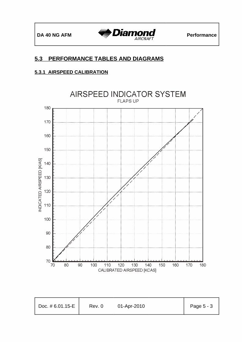
DA 40 NG AFM Performance
Doc. # 6.01.15-E Rev. 0 01-Apr-2010 Page 5 - 3
5.3 PERFORMANCE TABLES AND DIAGRAMS
5.3.1 AIRSPEED CALIBRATION
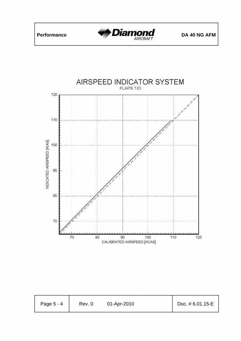
Performance DA 40 NG AFM
Page 5 - 4 Rev. 0 01-Apr-2010 Doc. # 6.01.15-E
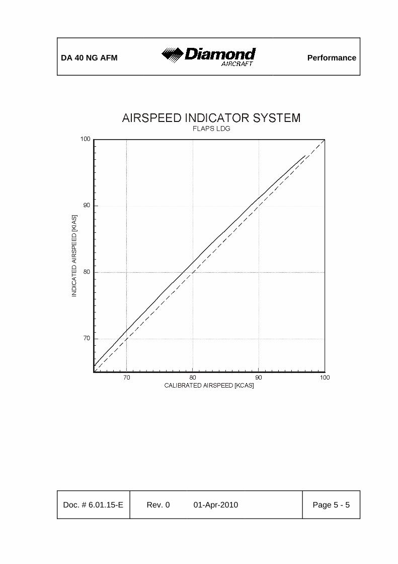
DA 40 NG AFM Performance
Doc. # 6.01.15-E Rev. 0 01-Apr-2010 Page 5 - 5
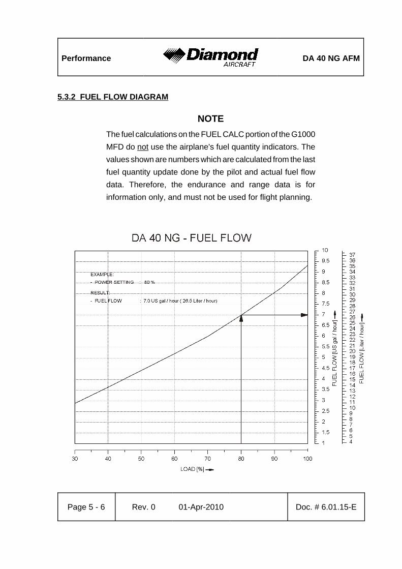
Performance DA 40 NG AFM
Page 5 - 6 Rev. 0 01-Apr-2010 Doc. # 6.01.15-E
5.3.2 FUEL FLOW DIAGRAM
NOTEThe fuel calculations on the FUEL CALC portion of the G1000MFD do not use the airplane's fuel quantity indicators. Thevalues shown are numbers which are calculated from the lastfuel quantity update done by the pilot and actual fuel flowdata. Therefore, the endurance and range data is forinformation only, and must not be used for flight planning.
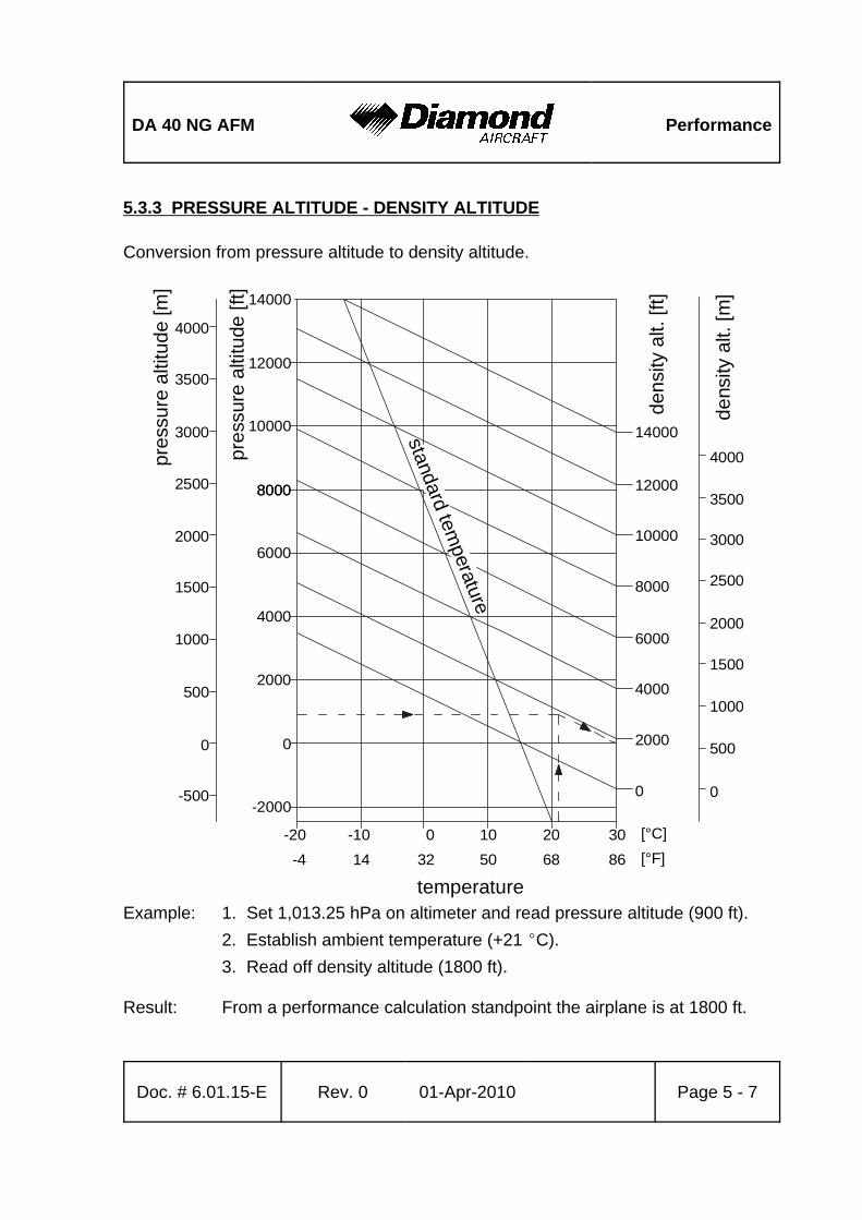
DA 40 NG AFM Performance
Doc. # 6.01.15-E Rev. 0 01-Apr-2010 Page 5 - 7
standard temperature
dens
ity a
lt. [f
t]
dens
ity a
lt. [m
]
pres
sure
alti
tude
[m]
pres
sure
alti
tude
[ft]
temperature
-2000
14000
12000
10000
12000
14000
10000
8000
6000
4000
2000
0
8000
8000
6000
4000
2000
0 0
500
1000
1500
2000
2500
3000
3500
4000
0
500
1000
1500
2000
2500
3000
3500
4000
-20 -10 0 10 20 30
-500
32 50 68 8614-4
[°C][°F]
5.3.3 PRESSURE ALTITUDE - DENSITY ALTITUDE
Conversion from pressure altitude to density altitude.
Example: 1. Set 1,013.25 hPa on altimeter and read pressure altitude (900 ft).2. Establish ambient temperature (+21 EC).3. Read off density altitude (1800 ft).
Result: From a performance calculation standpoint the airplane is at 1800 ft.
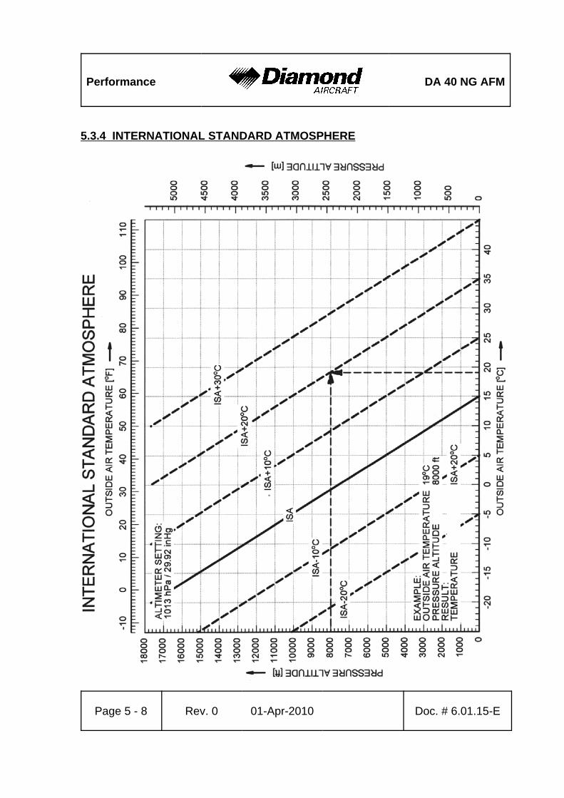
Performance DA 40 NG AFM
Page 5 - 8 Rev. 0 01-Apr-2010 Doc. # 6.01.15-E
5.3.4 INTERNATIONAL STANDARD ATMOSPHERE
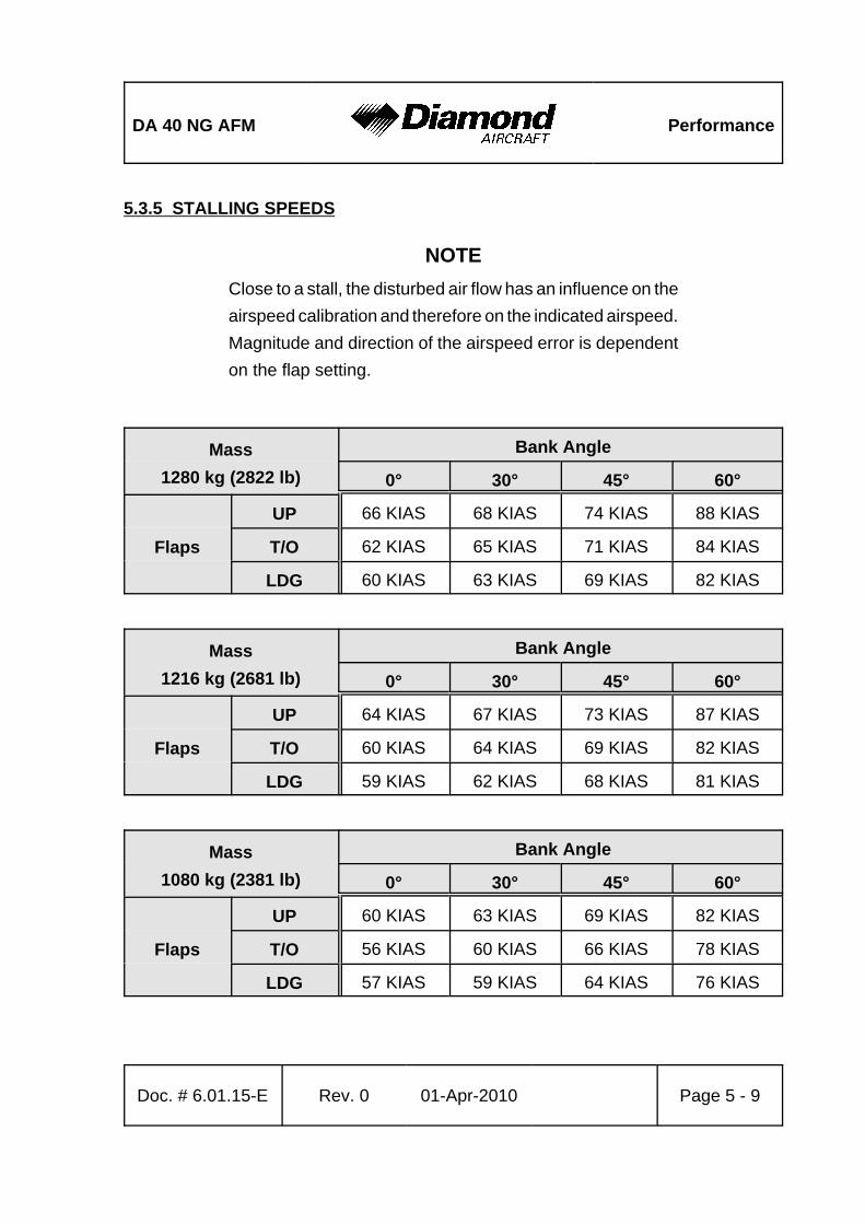
DA 40 NG AFM Performance
Doc. # 6.01.15-E Rev. 0 01-Apr-2010 Page 5 - 9
5.3.5 STALLING SPEEDS
NOTEClose to a stall, the disturbed air flow has an influence on theairspeed calibration and therefore on the indicated airspeed.Magnitude and direction of the airspeed error is dependenton the flap setting.
Mass1280 kg (2822 lb)
Bank Angle
0° 30° 45° 60°
Flaps
UP 66 KIAS 68 KIAS 74 KIAS 88 KIAS
T/O 62 KIAS 65 KIAS 71 KIAS 84 KIAS
LDG 60 KIAS 63 KIAS 69 KIAS 82 KIAS
Mass1216 kg (2681 lb)
Bank Angle
0° 30° 45° 60°
Flaps
UP 64 KIAS 67 KIAS 73 KIAS 87 KIAS
T/O 60 KIAS 64 KIAS 69 KIAS 82 KIAS
LDG 59 KIAS 62 KIAS 68 KIAS 81 KIAS
Mass1080 kg (2381 lb)
Bank Angle
0° 30° 45° 60°
Flaps
UP 60 KIAS 63 KIAS 69 KIAS 82 KIAS
T/O 56 KIAS 60 KIAS 66 KIAS 78 KIAS
LDG 57 KIAS 59 KIAS 64 KIAS 76 KIAS
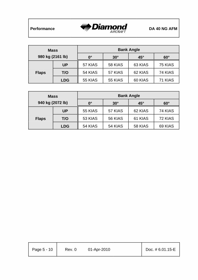
Performance DA 40 NG AFM
Page 5 - 10 Rev. 0 01-Apr-2010 Doc. # 6.01.15-E
Mass980 kg (2161 lb)
Bank Angle
0° 30° 45° 60°
Flaps
UP 57 KIAS 58 KIAS 63 KIAS 75 KIAS
T/O 54 KIAS 57 KIAS 62 KIAS 74 KIAS
LDG 55 KIAS 55 KIAS 60 KIAS 71 KIAS
Mass940 kg (2072 lb)
Bank Angle
0° 30° 45° 60°
Flaps
UP 55 KIAS 57 KIAS 62 KIAS 74 KIAS
T/O 53 KIAS 56 KIAS 61 KIAS 72 KIAS
LDG 54 KIAS 54 KIAS 58 KIAS 69 KIAS
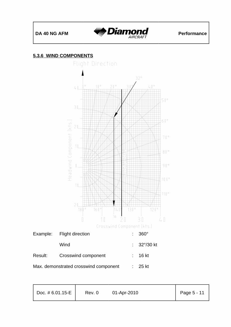
DA 40 NG AFM Performance
Doc. # 6.01.15-E Rev. 0 01-Apr-2010 Page 5 - 11
5.3.6 WIND COMPONENTS
Example: Flight direction : 360°
Wind : 32°/30 kt
Result: Crosswind component : 16 kt
Max. demonstrated crosswind component : 25 kt
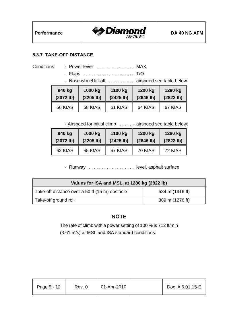
Performance DA 40 NG AFM
Page 5 - 12 Rev. 0 01-Apr-2010 Doc. # 6.01.15-E
5.3.7 TAKE-OFF DISTANCE
Conditions: - Power lever . . . . . . . . . . . . . . . MAX- Flaps . . . . . . . . . . . . . . . . . . . . T/O- Nose wheel lift-off . . . . . . . . . . . airspeed see table below:
940 kg(2072 lb)
1000 kg(2205 lb)
1100 kg(2425 lb)
1200 kg(2646 lb)
1280 kg(2822 lb)
56 KIAS 58 KIAS 61 KIAS 64 KIAS 67 KIAS
- Airspeed for initial climb . . . . . . airspeed see table below:
940 kg(2072 lb)
1000 kg(2205 lb)
1100 kg(2425 lb)
1200 kg(2646 lb)
1280 kg(2822 lb)
62 KIAS 65 KIAS 67 KIAS 70 KIAS 72 KIAS
- Runway . . . . . . . . . . . . . . . . . . level, asphalt surface
Values for ISA and MSL, at 1280 kg (2822 lb)
Take-off distance over a 50 ft (15 m) obstacle 584 m (1916 ft)
Take-off ground roll 389 m (1276 ft)
NOTEThe rate of climb with a power setting of 100 % is 712 ft/min(3.61 m/s) at MSL and ISA standard conditions.
DA 40 NG AFM Performance
Doc. # 6.01.15-E Rev. 0 01-Apr-2010 Page 5 - 13
WARNINGPoor maintenance condition of the airplane, deviation fromthe given procedures as well as unfavorable outsideconditions (high temperature, rain, unfavorable windconditions, including cross-wind) will increase the take-offdistance.
CAUTIONFor a safe take-off the available runway length must be atleast equal to the take-off distance over a 50 ft (15 m)obstacle.
CAUTIONThe figures in the following NOTE are typical values. On wetground or wet soft grass covered runways the take-off rollmay become significantly longer than stated below. In anycase the pilot must allow for the condition of the runway toensure a safe take-off.
NOTE For take-off from dry, short-cut grass covered runways, thefollowing corrections must be taken into account, comparedto paved runways (typical values, see CAUTION above):
- grass up to 5 cm (2 in) long: 10 % increase in take-off roll.- grass 5 to 10 cm (2 to 4 in) long: 30 % increase in take-off
roll.- grass longer than 10 cm (4 in): at least 45 % increase in
take-off roll.
Performance DA 40 NG AFM
Page 5 - 14 Rev. 0 01-Apr-2010 Doc. # 6.01.15-E
NOTEFor wet grass, an additional 20 % increase in take-off groundroll must be expected.
NOTEFor soft ground, an additional increase in take-off ground rollof at least 50 % must be expected.
NOTEAn uphill slope of 2 % (2 m per 100 m or 2 ft per 100 ft)results in an increase in the take-off distance of approximately17 %. The effect on the take-off roll can be greater.
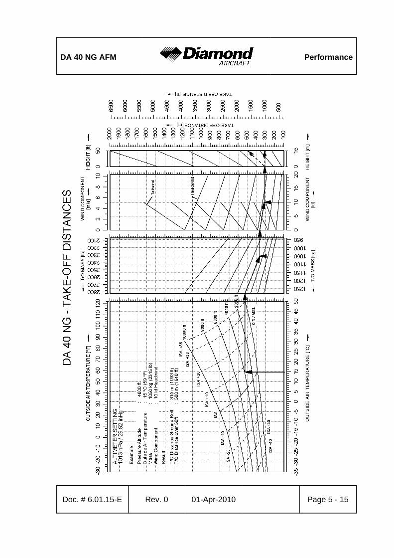
DA 40 NG AFM Performance
Doc. # 6.01.15-E Rev. 0 01-Apr-2010 Page 5 - 15

Performance DA 40 NG AFM
Page 5 - 16 Rev. 0 01-Apr-2010 Doc. # 6.01.15-E
Gradient ROC fpmTAS KTAS[%] [ ]
[ ] . = ⋅ 0 95
Gradient ROC m sTAS KTAS[%] [ / ]
[ ] = ⋅190
5.3.8 CLIMB PERFORMANCE - TAKE-OFF CLIMB
Conditions: - Power lever . . . . . . . . . . . . . . . 92% or max. 2100 RPM- Flaps . . . . . . . . . . . . . . . . . . . . T/O- Airspeed . . . . . . . . . . . . . . . . . . 72 KIAS
NOTEThe graph on the following page shows the rate of climb. Thegradient of climb cannot easily be determined with a graph,but it can be calculated using the following formulae:
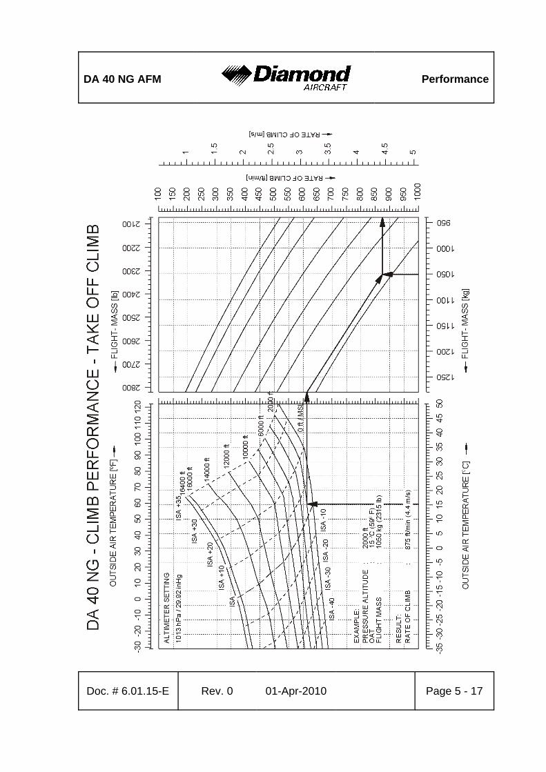
DA 40 NG AFM Performance
Doc. # 6.01.15-E Rev. 0 01-Apr-2010 Page 5 - 17
Performance DA 40 NG AFM
Page 5 - 18 Rev. 0 01-Apr-2010 Doc. # 6.01.15-E
Gradient ROC m sTAS KTAS[%] [ / ]
[ ] = ⋅190
Gradient ROC fpmTAS KTAS[%] [ ]
[ ] . = ⋅ 0 95
5.3.9 CLIMB PERFORMANCE - CRUISE CLIMB
Conditions: - Power lever . . . . . . . . . . . . . . . 92% or max. 2100 RPM- Flaps . . . . . . . . . . . . . . . . . . . . UP- Airspeed . . . . . . . . . . . . . . . . . . 88 KIAS
NOTEThe graph on the following page shows the rate of climb. Thegradient of climb cannot easily be determined with a graph,but it can be calculated using the following formulae:
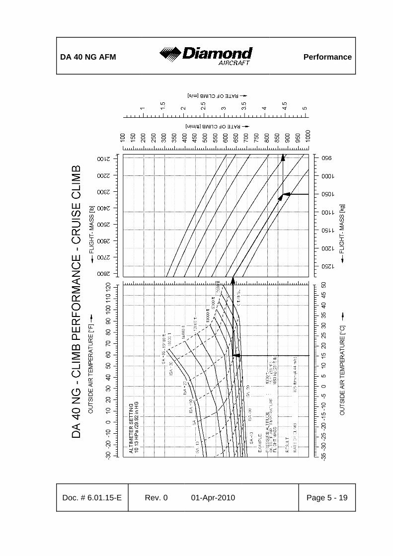
DA 40 NG AFM Performance
Doc. # 6.01.15-E Rev. 0 01-Apr-2010 Page 5 - 19
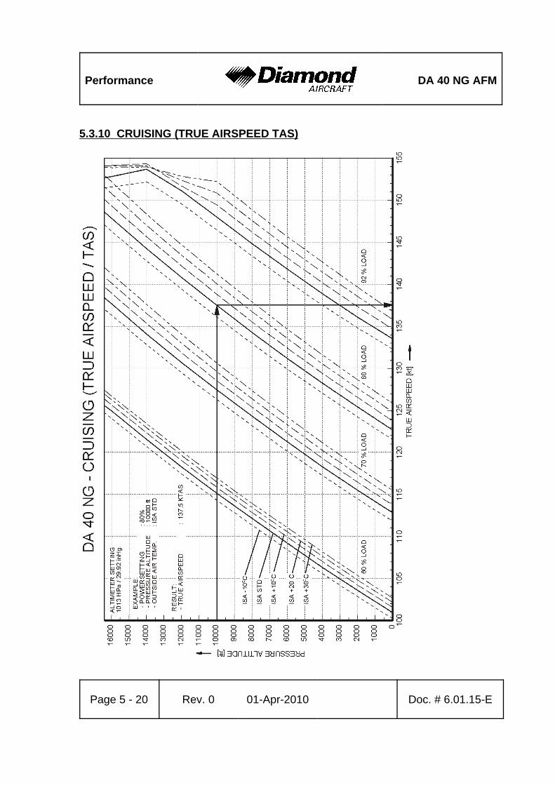
Performance DA 40 NG AFM
Page 5 - 20 Rev. 0 01-Apr-2010 Doc. # 6.01.15-E
5.3.10 CRUISING (TRUE AIRSPEED TAS)
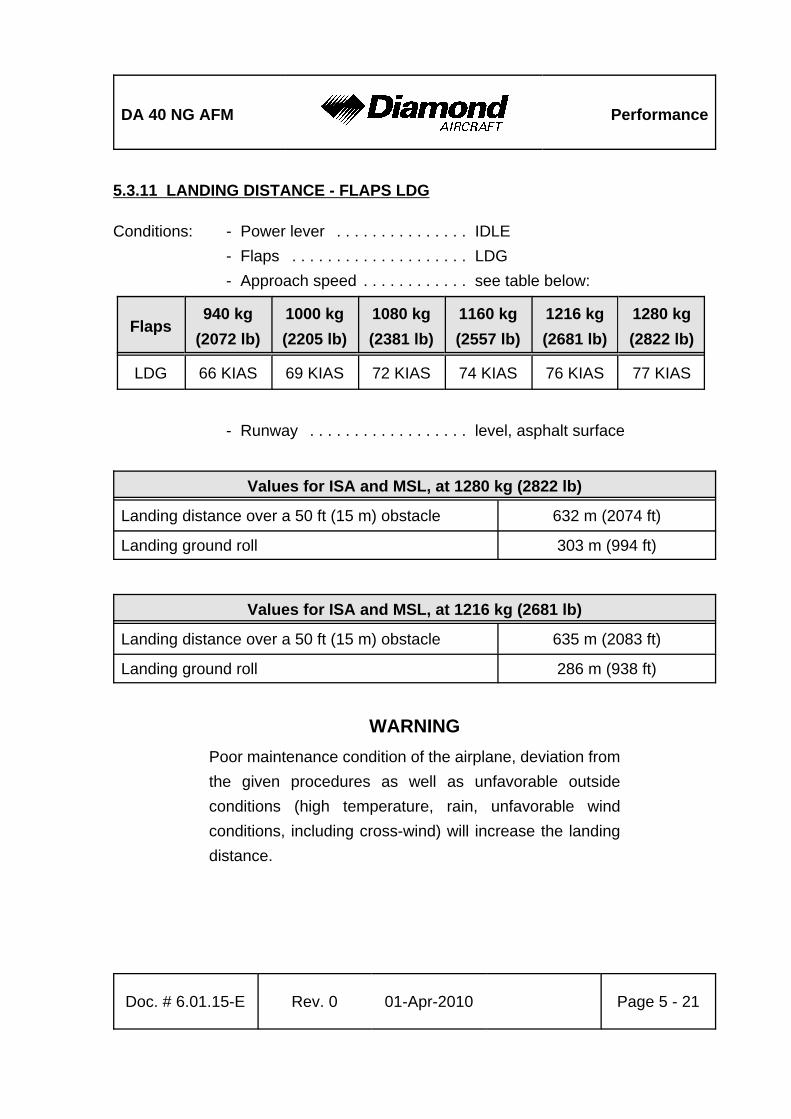
DA 40 NG AFM Performance
Doc. # 6.01.15-E Rev. 0 01-Apr-2010 Page 5 - 21
5.3.11 LANDING DISTANCE - FLAPS LDG
Conditions: - Power lever . . . . . . . . . . . . . . . IDLE- Flaps . . . . . . . . . . . . . . . . . . . . LDG- Approach speed . . . . . . . . . . . . see table below:
Flaps940 kg
(2072 lb)1000 kg(2205 lb)
1080 kg(2381 lb)
1160 kg(2557 lb)
1216 kg(2681 lb)
1280 kg(2822 lb)
LDG 66 KIAS 69 KIAS 72 KIAS 74 KIAS 76 KIAS 77 KIAS
- Runway . . . . . . . . . . . . . . . . . . level, asphalt surface
Values for ISA and MSL, at 1280 kg (2822 lb)
Landing distance over a 50 ft (15 m) obstacle 632 m (2074 ft)
Landing ground roll 303 m (994 ft)
Values for ISA and MSL, at 1216 kg (2681 lb)
Landing distance over a 50 ft (15 m) obstacle 635 m (2083 ft)
Landing ground roll 286 m (938 ft)
WARNINGPoor maintenance condition of the airplane, deviation fromthe given procedures as well as unfavorable outsideconditions (high temperature, rain, unfavorable windconditions, including cross-wind) will increase the landingdistance.
Performance DA 40 NG AFM
Page 5 - 22 Rev. 0 01-Apr-2010 Doc. # 6.01.15-E
CAUTIONFor a safe landing the available runway length must be atleast equal to the landing distance over a 50 ft (15 m)obstacle.
CAUTIONThe figures in the following NOTE are typical values. On wetground or wet soft grass covered runways the landingdistance may become significantly longer than stated below.In any case the pilot must allow for the condition of the runwayto ensure a safe landing.
NOTEFor landings on dry, short-cut grass covered runways, thefollowing corrections must be taken into account, comparedto paved runways:- grass up to 5 cm (2 in) long: 30 % increase in landing roll.- grass longer than 5 cm (2 in): at least 45 % increase in
landing roll.
NOTEFor wet grass or soft ground, an additional 15 % increase inlanding ground roll must be expected.
NOTEA downhill slope of 2 % (2 m per 100 m or 2 ft per 100 ft)results in an increase in the landing distance of approximately12 %. The effect on the landing roll can be greater.
NOTEHigher approach speeds result in a significant longer landingdistance during flare.
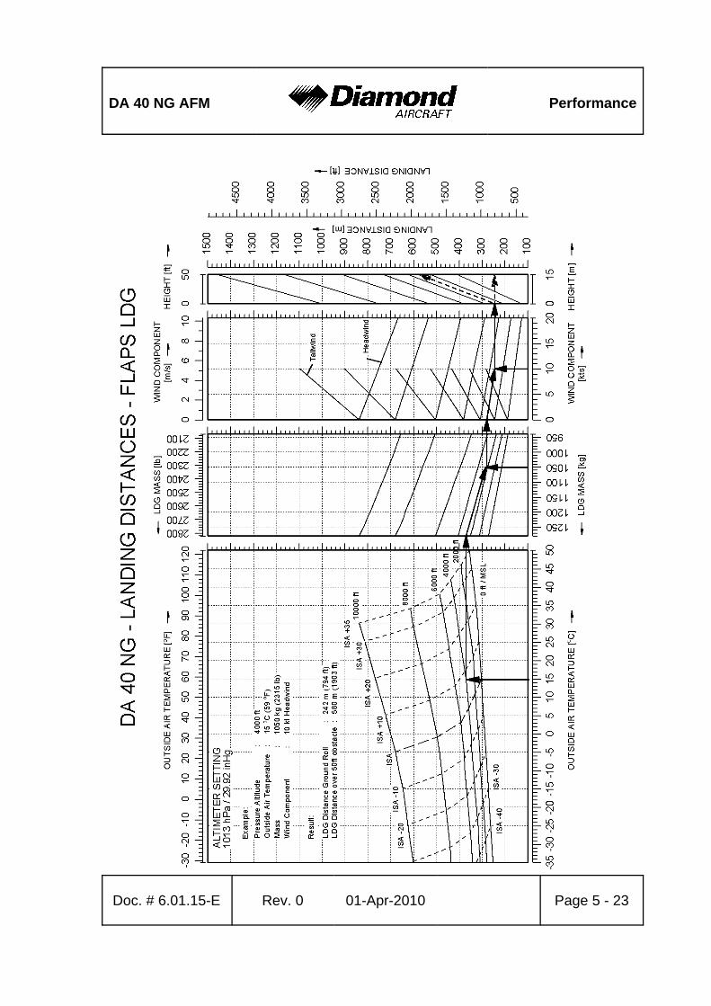
DA 40 NG AFM Performance
Doc. # 6.01.15-E Rev. 0 01-Apr-2010 Page 5 - 23
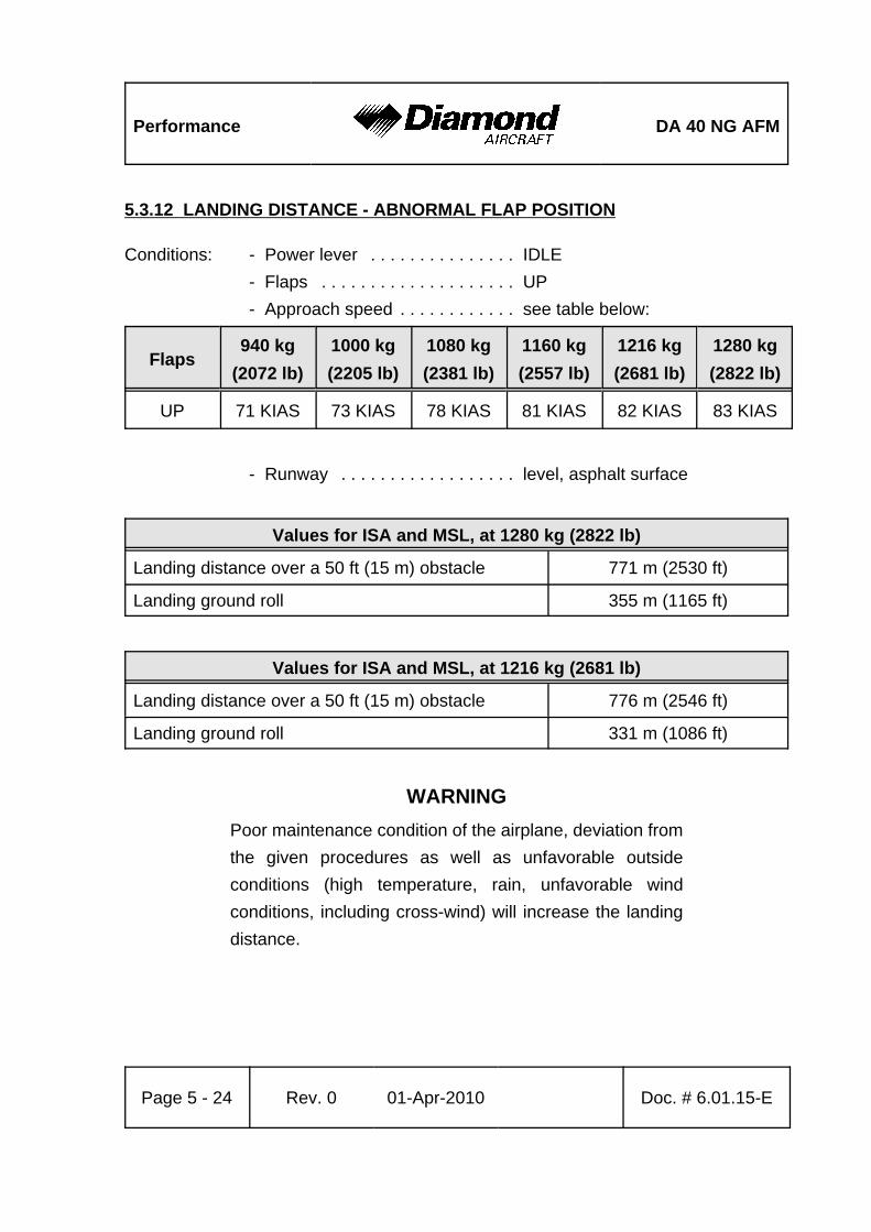
Performance DA 40 NG AFM
Page 5 - 24 Rev. 0 01-Apr-2010 Doc. # 6.01.15-E
5.3.12 LANDING DISTANCE - ABNORMAL FLAP POSITION
Conditions: - Power lever . . . . . . . . . . . . . . . IDLE- Flaps . . . . . . . . . . . . . . . . . . . . UP- Approach speed . . . . . . . . . . . . see table below:
Flaps940 kg
(2072 lb)1000 kg(2205 lb)
1080 kg(2381 lb)
1160 kg(2557 lb)
1216 kg(2681 lb)
1280 kg(2822 lb)
UP 71 KIAS 73 KIAS 78 KIAS 81 KIAS 82 KIAS 83 KIAS
- Runway . . . . . . . . . . . . . . . . . . level, asphalt surface
Values for ISA and MSL, at 1280 kg (2822 lb)
Landing distance over a 50 ft (15 m) obstacle 771 m (2530 ft)
Landing ground roll 355 m (1165 ft)
Values for ISA and MSL, at 1216 kg (2681 lb)
Landing distance over a 50 ft (15 m) obstacle 776 m (2546 ft)
Landing ground roll 331 m (1086 ft)
WARNINGPoor maintenance condition of the airplane, deviation fromthe given procedures as well as unfavorable outsideconditions (high temperature, rain, unfavorable windconditions, including cross-wind) will increase the landingdistance.
DA 40 NG AFM Performance
Doc. # 6.01.15-E Rev. 0 01-Apr-2010 Page 5 - 25
CAUTIONFor a safe landing the available runway length must be atleast equal to the landing distance over a 50 ft (15 m)obstacle.
CAUTIONThe figures in the following NOTE are typical values. On wetground or wet soft grass covered runways the landingdistance may become significantly longer than stated below.In any case the pilot must allow for the condition of the runwayto ensure a safe landing.
NOTEFor landings on dry, short-cut grass covered runways, thefollowing corrections must be taken into account, comparedto paved runways:
- grass up to 5 cm (2 in) long: 40 % increase in landing roll.- grass longer than 5 cm (2 in): at least 60 % increase in
landing roll.
NOTEFor wet grass or soft ground, an additional 20 % increase inlanding ground roll must be expected.
NOTEA downhill slope of 2 % (2 m per 100 m or 2 ft per 100 ft)results in an increase in the landing distance of approximately10 %. The effect on the landing roll can be greater.
NOTEHigher approach speeds result in a significant longer landingdistance during flare.
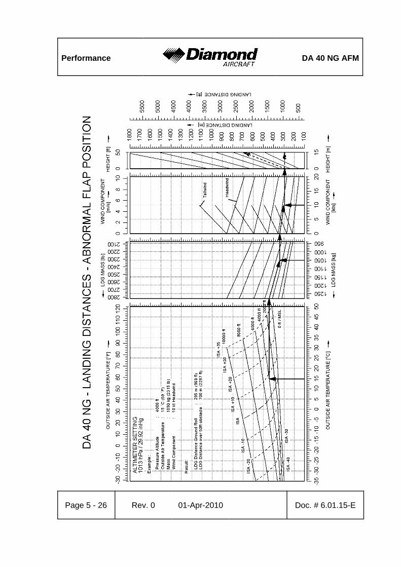
Performance DA 40 NG AFM
Page 5 - 26 Rev. 0 01-Apr-2010 Doc. # 6.01.15-E
DA 40 NG AFM Performance
Doc. # 6.01.15-E Rev. 0 01-Apr-2010 Page 5 - 27
5.3.13 GRADIENT OF CLIMB ON GO-AROUND
Landing Mass 1216 kg (2681 lb)
Conditions:
- Power lever . . . . . . . . . . . . . . . . . . . . . . . . . MAX- Flaps . . . . . . . . . . . . . . . . . . . . . . . . . . . . . . LDG- Airspeed: . . . . . . . . . . . . . . . . . . . . . . . . . . . 76 KIAS
Value for ISA and MSL, at 1216 kg (2681 lb)
Constant gradient of climb 6.6 % (equals 3.8° climb angle) or 492 ft/min
Landing Mass above 1216 kg (2681 lb) up to 1280 kg (2822 lb)
NOTEA landing with a mass between 1216 kg (2681 lb) and1280 kg (2822 lb) is admissible. It constitutes an abnormaloperating procedure. Refer to Section 4B.8.
Conditions:
- Power lever . . . . . . . . . . . . . . . . . . . . . . . . . MAX- Flaps . . . . . . . . . . . . . . . . . . . . . . . . . . . . . . LDG- Airspeed: . . . . . . . . . . . . . . . . . . . . . . . . . . . 77 KIAS
Value for ISA and MSL, at 1280 kg (2822 lb)
Constant gradient of climb 5.5 % (equals 3.1° climb angle) or 420 ft/min
Performance DA 40 NG AFM
Page 5 - 28 Rev. 0 01-Apr-2010 Doc. # 6.01.15-E
5.3.14 GLIDE
The following table shows the glide ratio and the resulting maximum horizontal distancein nautical miles per 1000 ft (305 m) of altitude loss in a glide traveled in still air.
Glide ratio Maximum horizontal distanceper 1000 ft (305 m) altitude loss
Windmillingpropeller 1 : 9.7 1.59 NM (2.94 km)
Conditions:- Flaps . . . . . . . . . . . . . . . . . . . . . . . . . . . . . . UP- Airspeed . . . . . . . . . . . . . . . . . . . . . . . . . . . . 88 KIAS
CAUTIONThe propeller will keep windmilling under all expectedconditions. Do not attempt to stop the propeller intentionally.
NOTEIn case of stationary propeller the given numbers areconservative.
DA 40 NG AFM Performance
Doc. # 6.01.15-E Rev. 0 01-Apr-2010 Page 5 - 29
5.3.15 APPROVED NOISE DATA
ICAO Annex 16 Chapter X . . . . . . . . . . . . . . . . . . 74.5 dB(A) CS-36 Subpart C . . . . . . . . . . . . . . . . . . . . . . . . . 74.5 dB(A)

Performance DA 40 NG AFM
Page 5 - 30 Rev. 0 01-Apr-2010 Doc. # 6.01.15-E
Intentionally left blank.
DA 40 NG AFM Mass & Balance
Doc. # 6.01.15-E Rev. 0 01-Apr-2010 Page 6 - 1
CHAPTER 6MASS AND BALANCE / EQUIPMENT LIST
Page
6.1 INTRODUCTION . . . . . . . . . . . . . . . . . . . . . . . . . . . . . . . . . . . . . . . 6-26.2 DATUM PLANE . . . . . . . . . . . . . . . . . . . . . . . . . . . . . . . . . . . . . . . . 6-36.3 MASS AND BALANCE REPORT . . . . . . . . . . . . . . . . . . . . . . . . . . 6-36.4 FLIGHT MASS AND CENTER OF GRAVITY . . . . . . . . . . . . . . . . . 6-5
6.4.1 MOMENT ARMS . . . . . . . . . . . . . . . . . . . . . . . . . . . . . . . . . . 6-76.4.2 LOADING DIAGRAM . . . . . . . . . . . . . . . . . . . . . . . . . . . . . . 6-86.4.3 CALCULATION OF LOADING CONDITION . . . . . . . . . . . . . 6-96.4.4 PERMISSIBLE CENTER OF GRAVITY RANGE . . . . . . . . 6-136.4.5 PERMISSIBLE MOMENT RANGE . . . . . . . . . . . . . . . . . . . 6-14
6.5 EQUIPMENT LIST AND EQUIPMENT INVENTORY . . . . . . . . . . 6-15
Mass & Balance DA 40 NG AFM
Page 6 - 2 Rev. 0 01-Apr-2010 Doc. # 6.01.15-E
6.1 INTRODUCTION
In order to achieve the performance and flight characteristics described in this AirplaneFlight Manual and for safe flight operation, the airplane must be operated within thepermissible mass and balance envelope.
The pilot is responsible for adhering to the permissible values for loading and center ofgravity (CG). In this, he should note the movement of the CG due to fuel consumption.The permissible CG range during flight is given in Chapter 2.
The procedure for determining the flight mass CG position is described in this Chapter.Over and above this there is a comprehensive list of the equipment approved for thisairplane (Equipment List), as also a list of that equipment installed when the airplane wasweighed (Equipment Inventory).
Before the airplane is delivered the empty mass and the corresponding CG position aredetermined, and entered in Section 6.3 - MASS AND BALANCE REPORT.
NOTEFollowing equipment changes the new empty mass and thecorresponding CG position must be determined by calculationor by weighing.
Following repairs or repainting the new empty mass and thecorresponding CG position must be determined by weighing.
Empty mass, empty mass CG position, and the empty massmoment must be certified in the Mass and Balance Reportby an authorized person.
DA 40 NG AFM Mass & Balance
Doc. # 6.01.15-E Rev. 0 01-Apr-2010 Page 6 - 3
NOTERefer to Section 1.6 UNITS OF MEASUREMENT forconversion of SI units to US units and vice versa.
6.2 DATUM PLANE
The Datum Plane (DP) is a plane which is normal to the airplane’s longitudinal axis andin front of the airplane as seen from the direction of flight. The airplane’s longitudinal axisis parallel with the upper surface of a 600:31 wedge which is placed on top of the rearfuselage in front of the vertical stabilizer. When the upper surface of the wedge is alignedhorizontally, the Datum Plane is vertical. The Datum Plane is located 2.194 meter(86.38 in) forward of the most forward point of the root rib on the stub wing.
6.3 MASS AND BALANCE REPORT
The empty mass and the corresponding CG position established before delivery are thefirst entries in the Mass and Balance Report. Every change in permanently installedequipment, and every repair to the airplane which affects the empty mass or the emptymass CG must be recorded in the Mass and Balance Report.
For the calculation of flight mass and corresponding CG position (or moment), the currentempty mass and the corresponding CG position (or moment) in accordance with the Massand Balance Report must always be used.
Condition of the airplane for establishing the empty mass:
- Equipment as per Equipment Inventory (see Section 6.5)
- Including brake fluid, lubricant (1.0 liter / 1.06 qts), coolant (7.5 liter / 7.93 qts), gearboxoil (2.1liter / 2.22 qts), engine oil (7.0 liter / 7.4 qts), plus unusable fuel (2.0 US gal/ approx. 7.6 liter).
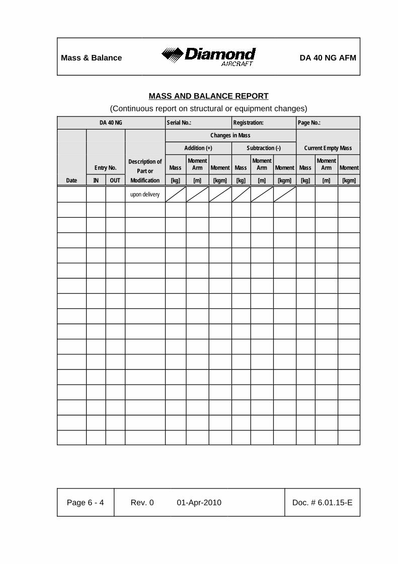
Mass & Balance DA 40 NG AFM
Page 6 - 4 Rev. 0 01-Apr-2010 Doc. # 6.01.15-E
MASS AND BALANCE REPORT(Continuous report on structural or equipment changes)
DA 40 NG Serial No.: Registration: Page No.:
Date
Entry No.Description of
Part orModification
Changes in Mass
Current Empty MassAddition (+) Subtraction (-)
MassMoment
Arm Moment MassMoment
Arm Moment MassMoment
Arm Moment
IN OUT [kg] [m] [kgm] [kg] [m] [kgm] [kg] [m] [kgm]
upon delivery

DA 40 NG AFM Mass & Balance
Doc. # 6.01.15-E Rev. 0 01-Apr-2010 Page 6 - 5
6.4 FLIGHT MASS AND CENTER OF GRAVITY
The following information enables you to operate your DA 40 NG within the permissiblemass and balance limits. For the calculation of the flight mass and the corresponding CGposition the following tables and diagrams are required:
6.4.1 - MOMENT ARMS6.4.2 - LOADING DIAGRAM6.4.3 - CALCULATION OF LOADING CONDITION6.4.4 - PERMISSIBLE CENTER OF GRAVITY RANGE6.4.5 - PERMISSIBLE MOMENT RANGE
The diagrams should be used as follows:
1. Take the empty mass and the empty mass moment of your airplane from the Massand Balance Report, and enter the figures in the appropriate boxes under the columnmarked ‘Your DA 40 NG' in Table 6.4.3 - CALCULATION OF LOADING CONDITION.
2. Read the fuel quantity indicators to determine the fuel quantity. If an indicator shows14 US gal, up to 19.5 US gal can be in the Long Range Tank. In this case, the exactquantity must be determined with the alternate means for fuel quantity indication.
3. Multiply the individual masses by the moment arms quoted to obtain the moment forevery item of loading and enter these moments in the appropriate boxes in Table6.4.3 - CALCULATION OF LOADING CONDITION.
4. Add up the masses and moments in the respective columns. The total moments maybe rounded to whole numbers. The CG position is calculated by dividing the totalmoment by the total mass (using row 6 for the condition with empty fuel tanks, androw 8 for the pre take-off condition). The resulting CG position must be inside the limits.
As an illustration the total mass and the CG position are entered on Diagram6.4.4 - PERMISSIBLE CENTER OF GRAVITY RANGE. This checks graphically thatthe current configuration of the airplane is within the permissible range.

Mass & Balance DA 40 NG AFM
Page 6 - 6 Rev. 0 01-Apr-2010 Doc. # 6.01.15-E
5. Graphical method:
Diagram 6.4.2 - LOADING DIAGRAM is used to determine the moments. The massesand moments for the individual items of loading are added. Then Diagram6.4.5 - PERMISSIBLE MOMENT RANGE is used to check whether the total momentassociated with the total mass is in the admissible range.
The result found with the graphical method is however inaccurate. In doubtful casesthe result must be verified using the exact method given above.
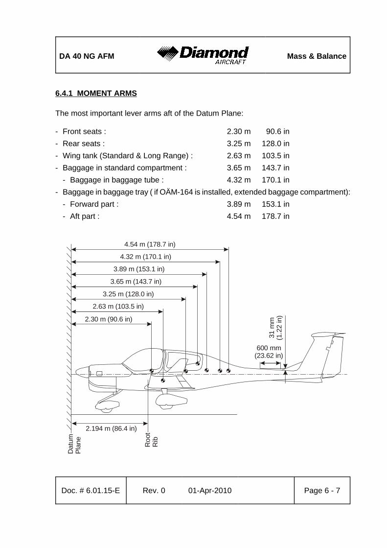
DA 40 NG AFM Mass & Balance
Doc. # 6.01.15-E Rev. 0 01-Apr-2010 Page 6 - 7
2.194 m (86.4 in)
Dat
umPl
ane
Roo
tR
ib
2.30 m (90.6 in)
2.63 m (103.5 in)
3.25 m (128.0 in)
3.65 m (143.7 in)
3.89 m (153.1 in)
4.32 m (170.1 in)
4.54 m (178.7 in)
600 mm(23.62 in)
31 m
m(1
.22
in)
6.4.1 MOMENT ARMS
The most important lever arms aft of the Datum Plane:
- Front seats : 2.30 m 90.6 in- Rear seats : 3.25 m 128.0 in- Wing tank (Standard & Long Range) : 2.63 m 103.5 in- Baggage in standard compartment : 3.65 m 143.7 in
- Baggage in baggage tube : 4.32 m 170.1 in- Baggage in baggage tray ( if OÄM-164 is installed, extended baggage compartment):
- Forward part : 3.89 m 153.1 in- Aft part : 4.54 m 178.7 in
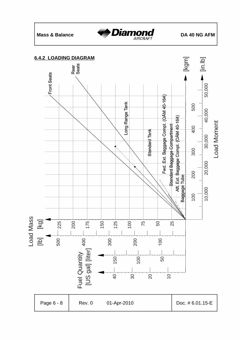
Mass & Balance DA 40 NG AFM
Page 6 - 8 Rev. 0 01-Apr-2010 Doc. # 6.01.15-E
2550100
125
150
175
200
225 75[kg]
[lb]
Load
Mas
s
10,0
0020
,000
30,0
0040
,000
50,0
00
100
200
300
400
500
[kgm
]
[in.lb
]
50100
150
10203040
Fuel
Qua
ntity
[US
gal
] [lit
er]
Load
Mom
ent
6.4.2 LOADING DIAGRAM
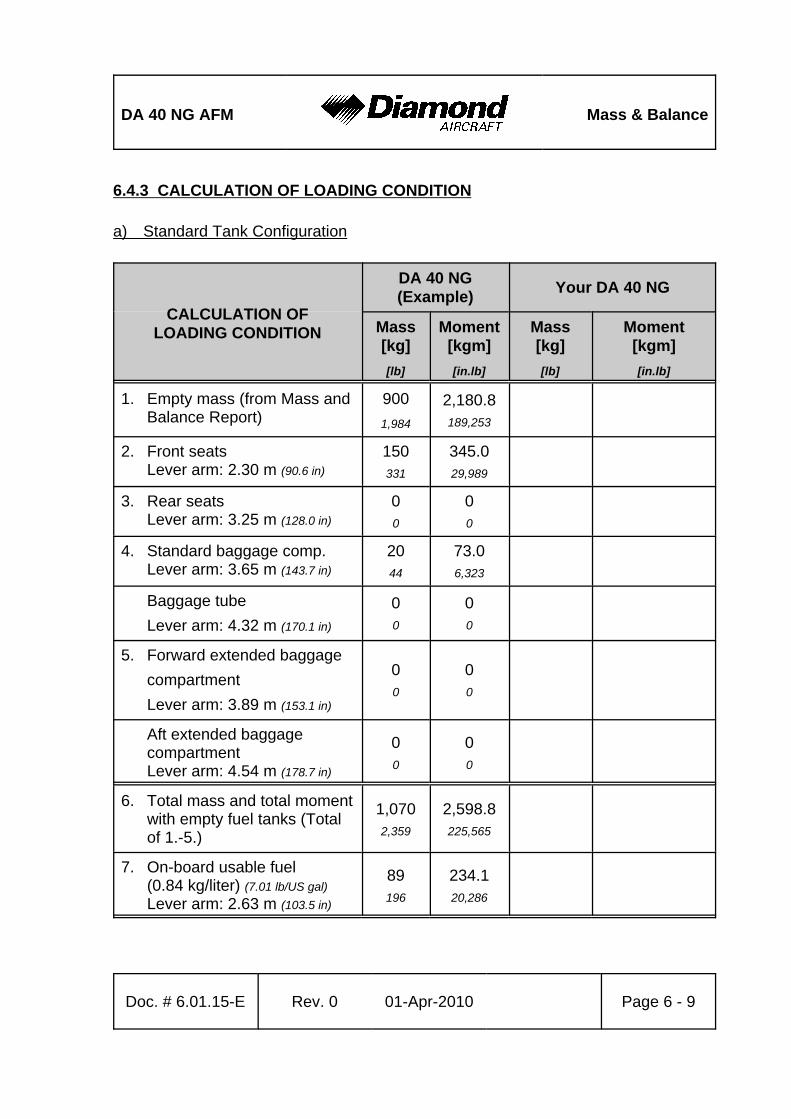
DA 40 NG AFM Mass & Balance
Doc. # 6.01.15-E Rev. 0 01-Apr-2010 Page 6 - 9
6.4.3 CALCULATION OF LOADING CONDITION
a) Standard Tank Configuration
CALCULATION OFLOADING CONDITION
DA 40 NG(Example) Your DA 40 NG
Mass[kg][lb]
Moment[kgm][in.lb]
Mass[kg][lb]
Moment[kgm][in.lb]
1. Empty mass (from Mass andBalance Report)
9001,984
2,180.8189,253
2. Front seatsLever arm: 2.30 m (90.6 in)
150331
345.029,989
3. Rear seatsLever arm: 3.25 m (128.0 in)
00
00
4. Standard baggage comp.Lever arm: 3.65 m (143.7 in)
2044
73.06,323
Baggage tubeLever arm: 4.32 m (170.1 in)
00
00
5. Forward extended baggagecompartmentLever arm: 3.89 m (153.1 in)
00
00
Aft extended baggagecompartmentLever arm: 4.54 m (178.7 in)
00
00
6. Total mass and total momentwith empty fuel tanks (Totalof 1.-5.)
1,0702,359
2,598.8225,565
7. On-board usable fuel(0.84 kg/liter) (7.01 lb/US gal)Lever arm: 2.63 m (103.5 in)
89196
234.120,286
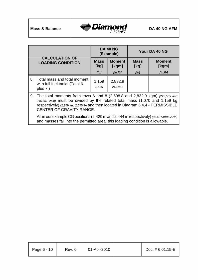
Mass & Balance DA 40 NG AFM
CALCULATION OFLOADING CONDITION
DA 40 NG(Example) Your DA 40 NG
Mass[kg][lb]
Moment[kgm][in.lb]
Mass[kg][lb]
Moment[kgm][in.lb]
Page 6 - 10 Rev. 0 01-Apr-2010 Doc. # 6.01.15-E
8. Total mass and total momentwith full fuel tanks (Total 6.plus 7.)
1,1592,555
2,832.9245,851
9. The total moments from rows 6 and 8 (2,598.8 and 2,832.9 kgm) (225,565 and245,851 in.lb) must be divided by the related total mass (1,070 and 1,159 kgrespectively) (2,359 and 2,555 lb) and then located in Diagram 6.4.4 - PERMISSIBLECENTER OF GRAVITY RANGE.
As in our example CG positions (2.429 m and 2.444 m respectively) (95.62 and 96.22 in)and masses fall into the permitted area, this loading condition is allowable.
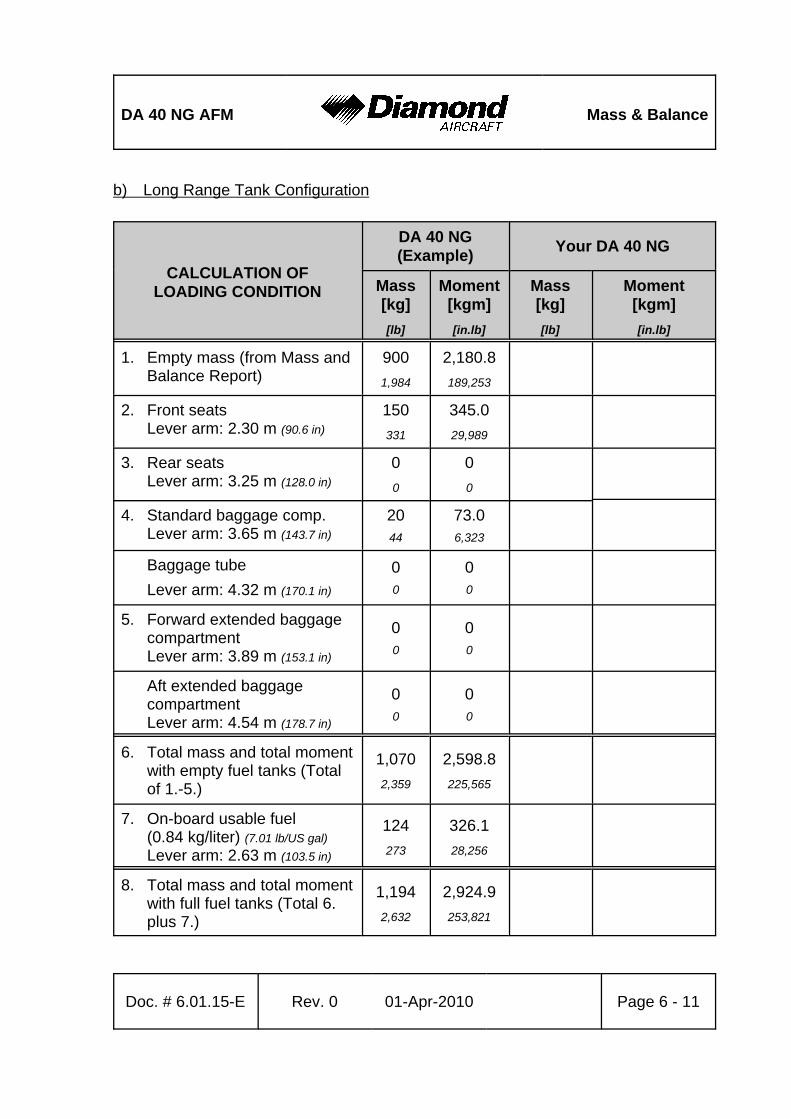
DA 40 NG AFM Mass & Balance
Doc. # 6.01.15-E Rev. 0 01-Apr-2010 Page 6 - 11
b) Long Range Tank Configuration
CALCULATION OFLOADING CONDITION
DA 40 NG(Example) Your DA 40 NG
Mass[kg][lb]
Moment[kgm][in.lb]
Mass[kg][lb]
Moment[kgm][in.lb]
1. Empty mass (from Mass andBalance Report)
9001,984
2,180.8189,253
2. Front seatsLever arm: 2.30 m (90.6 in)
150331
345.029,989
3. Rear seatsLever arm: 3.25 m (128.0 in)
00
00
4. Standard baggage comp.Lever arm: 3.65 m (143.7 in)
2044
73.06,323
Baggage tubeLever arm: 4.32 m (170.1 in)
00
00
5. Forward extended baggagecompartmentLever arm: 3.89 m (153.1 in)
00
00
Aft extended baggagecompartmentLever arm: 4.54 m (178.7 in)
00
00
6. Total mass and total momentwith empty fuel tanks (Totalof 1.-5.)
1,0702,359
2,598.8225,565
7. On-board usable fuel(0.84 kg/liter) (7.01 lb/US gal)Lever arm: 2.63 m (103.5 in)
124273
326.128,256
8. Total mass and total momentwith full fuel tanks (Total 6.plus 7.)
1,1942,632
2,924.9253,821
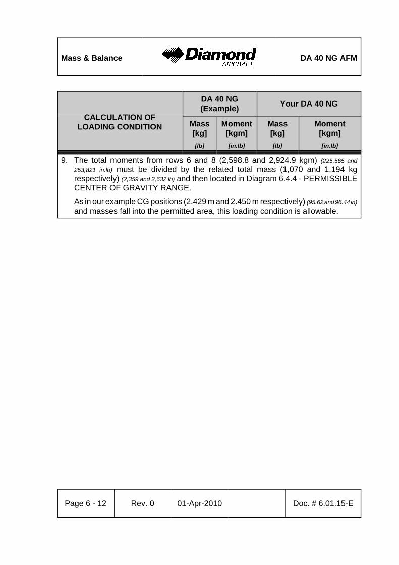
Mass & Balance DA 40 NG AFM
CALCULATION OFLOADING CONDITION
DA 40 NG(Example) Your DA 40 NG
Mass[kg][lb]
Moment[kgm][in.lb]
Mass[kg][lb]
Moment[kgm][in.lb]
Page 6 - 12 Rev. 0 01-Apr-2010 Doc. # 6.01.15-E
9. The total moments from rows 6 and 8 (2,598.8 and 2,924.9 kgm) (225,565 and253,821 in.lb) must be divided by the related total mass (1,070 and 1,194 kgrespectively) (2,359 and 2,632 lb) and then located in Diagram 6.4.4 - PERMISSIBLECENTER OF GRAVITY RANGE.
As in our example CG positions (2.429 m and 2.450 m respectively) (95.62 and 96.44 in)and masses fall into the permitted area, this loading condition is allowable.
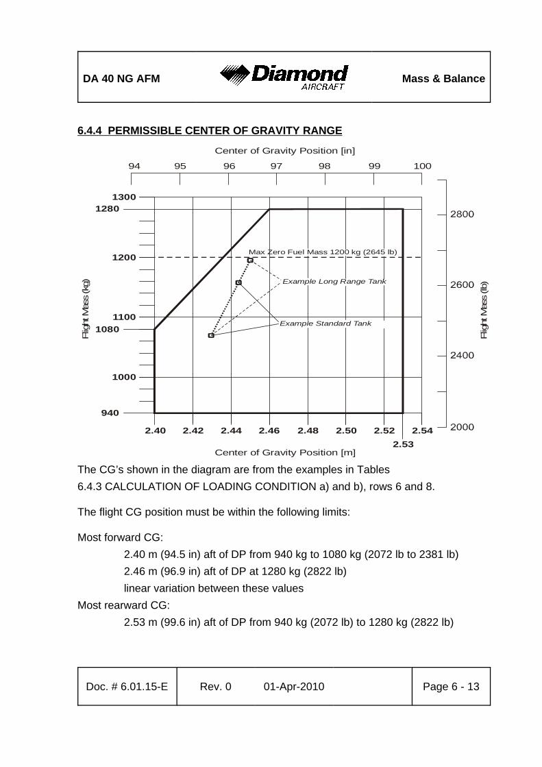
DA 40 NG AFM Mass & Balance
Doc. # 6.01.15-E Rev. 0 01-Apr-2010 Page 6 - 13
6.4.4 PERMISSIBLE CENTER OF GRAVITY RANGE
The CG’s shown in the diagram are from the examples in Tables6.4.3 CALCULATION OF LOADING CONDITION a) and b), rows 6 and 8.
The flight CG position must be within the following limits:
Most forward CG:2.40 m (94.5 in) aft of DP from 940 kg to 1080 kg (2072 lb to 2381 lb)2.46 m (96.9 in) aft of DP at 1280 kg (2822 lb)linear variation between these values
Most rearward CG:2.53 m (99.6 in) aft of DP from 940 kg (2072 lb) to 1280 kg (2822 lb)
1300
1200
1280
Max Zero Fuel Mass 1200 kg (2645 lb)
11001080
1000
940
2.40 2.42 2.44 2.46 2.48 2.50 2.52 2.542.53
Center of Gravity Position [m]
Flig
ht M
ass
(kg)
100999897969594
Center of Gravity Position [in]
Flig
ht M
ass
(lb)
Example Standard Tank
Example Long Range Tank
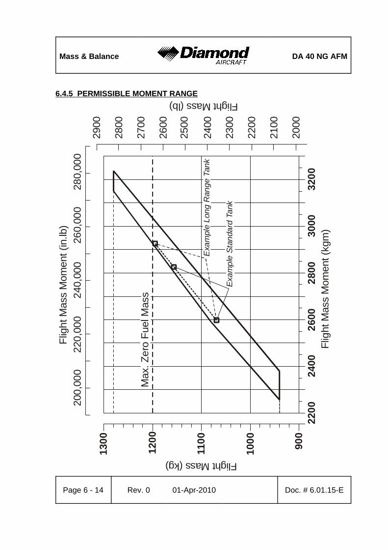
Mass & Balance DA 40 NG AFM
Page 6 - 14 Rev. 0 01-Apr-2010 Doc. # 6.01.15-E
1300
1200
1100
1000 90
022
0024
0026
00Fl
ight
Mas
s M
omen
t (kg
m)
2800
3000
3200
Flight Mass (kg)
2500
2400
2300
2200
2100
2000
Flight Mass (lb)
200,
000
220,
000
240,
000
260,
000
Flig
ht M
ass
Mom
ent (
in.lb
)
Max
. Zer
o Fu
el M
ass
2600
2700
2800
2900
280,
000
Exa
mpl
e S
tand
ard
Tank
Exa
mpl
e Lo
ng R
ange
Tan
k
6.4.5 PERMISSIBLE MOMENT RANGE
DA 40 NG AFM Mass & Balance
Doc. # 6.01.15-E Rev. 0 01-Apr-2010 Page 6 - 15
6.5 EQUIPMENT LIST AND EQUIPMENT INVENTORY
All equipment approved for installation in the DA 40 NG is shown in the Equipment Listbelow.
The items of equipment installed in your particular airplane are indicated in the appropriatecolumn. The set of items marked as 'installed' constitutes the Equipment Inventory.
NOTEThe equipment listed below cannot be installed in anyarbitrary combination. The airplane manufacturer must becontacted before removing or installing equipment, with theexception of replacing a unit by an identical unit.
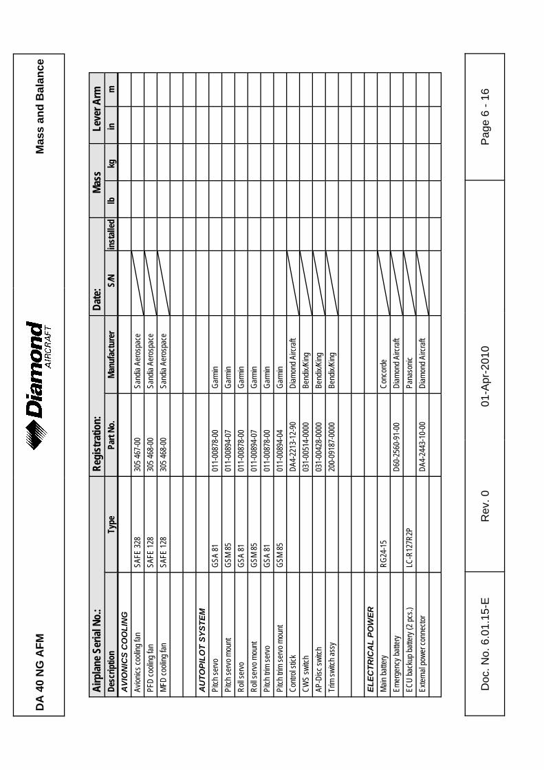
DA
40
NG
AFM
Mas
s an
d B
alan
ce
Doc
. No.
6.0
1.15
-ER
ev. 0
01-A
pr-2
010
Pag
e 6
- 16
Airp
lane S
erial
No.
:Re
gist
ratio
n:Da
te:
Mass
Leve
r Arm
Desc
riptio
nTy
pePa
rt No
.Ma
nufa
ctur
erS/
Nin
stall
edlb
kgin
mA
VIO
NIC
S C
OO
LIN
GAv
ionics
cooli
ng fa
nSA
FE 32
830
5 467
-00
Sand
ia Ae
rosp
ace
PFD
cooli
ng fa
nSA
FE 12
830
5 468
-00
Sand
ia Ae
rosp
ace
MFD
cooli
ng fa
nSA
FE 12
830
5 468
-00
Sand
ia Ae
rosp
ace
AU
TOPI
LOT
SYST
EMPi
tch se
rvoGS
A 81
011-
0087
8-00
Garm
inPi
tch se
rvo m
ount
GSM
8501
1-00
894-
07Ga
rmin
Roll s
ervo
GSA
8101
1-00
878-
00Ga
rmin
Roll s
ervo
mou
ntGS
M 85
011-
0089
4-07
Garm
inPi
tch tr
im se
rvoGS
A 81
011-
0087
8-00
Garm
inPi
tch tr
im se
rvo m
ount
GSM
8501
1-00
894-
04Ga
rmin
Contr
ol sti
ckDA
4-22
13-1
2-90
Diam
ond A
ircra
ftCW
S sw
itch
031-
0051
4-00
00Be
ndix/
King
AP-D
isc sw
itch
031-
0042
8-00
00Be
ndix/
King
Trim
switc
h ass
y20
0-09
187-
0000
Bend
ix/Ki
ng
ELEC
TRIC
AL
POW
ERMa
in ba
ttery
RG24
-15
Conc
orde
Emer
genc
y batt
ery
D60-
2560
-91-
00Di
amon
d Airc
raft
ECU
back
up ba
ttery
(2 pc
s.)LC
-R12
7R2P
Pana
sonic
Exter
nal p
ower
conn
ector
DA4-
2443
-10-
00Di
amon
d Airc
raft
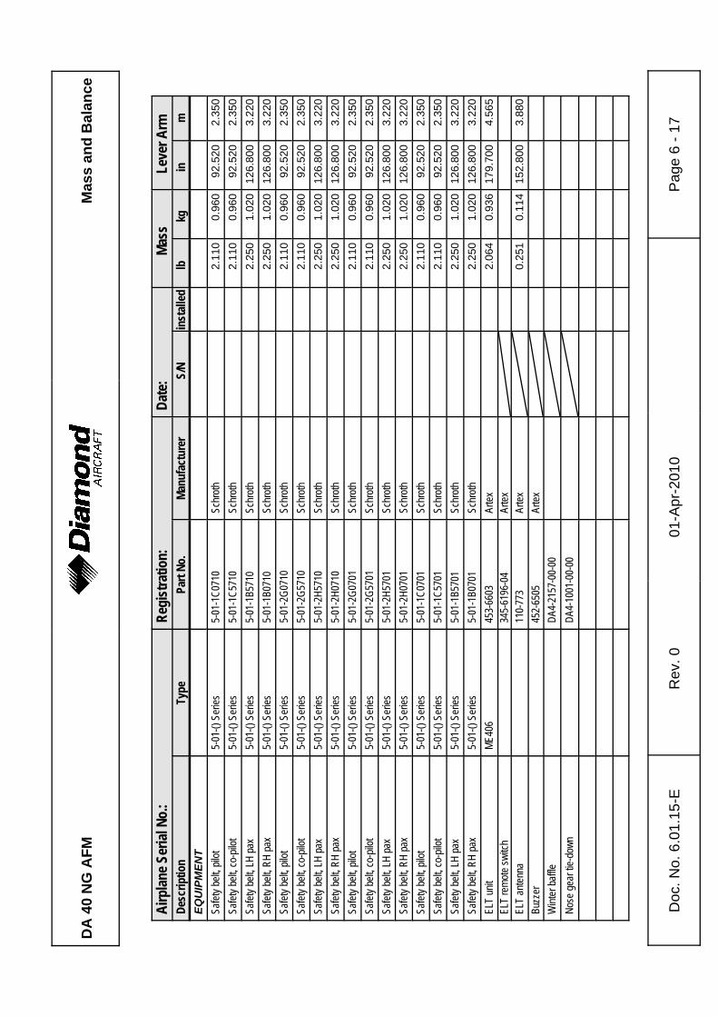
DA
40
NG
AFM
Mas
s an
d B
alan
ce
Airp
lane S
erial
No.
:Re
gist
ratio
n:Da
te:
Mass
Leve
r Arm
Desc
riptio
nTy
pePa
rt No
.Ma
nufa
ctur
erS/
Nin
stall
edlb
kgin
m
Doc
. No.
6.0
1.15
-ER
ev. 0
01-A
pr-2
010
Pag
e 6
- 17
EQU
IPM
ENT
Safet
y belt
, pilo
t5-
01-()
Ser
ies5-
01-1
C071
0Sc
hroth
2.11
00.
960
92.5
202.
350
Safet
y belt
, co-
pilot
5-01
-() S
eries
5-01
-1C5
710
Schr
oth2.
110
0.96
092
.520
2.35
0Sa
fety b
elt, L
H pa
x5-
01-()
Ser
ies5-
01-1
B571
0Sc
hroth
2.25
01.
020
126.
800
3.22
0Sa
fety b
elt, R
H pa
x5-
01-()
Ser
ies5-
01-1
B071
0Sc
hroth
2.25
01.
020
126.
800
3.22
0Sa
fety b
elt, p
ilot
5-01
-() S
eries
5-01
-2G0
710
Schr
oth2.
110
0.96
092
.520
2.35
0Sa
fety b
elt, c
o-pil
ot5-
01-()
Ser
ies5-
01-2
G571
0Sc
hroth
2.11
00.
960
92.5
202.
350
Safet
y belt
, LH
pax
5-01
-() S
eries
5-01
-2H5
710
Schr
oth2.
250
1.02
012
6.80
03.
220
Safet
y belt
, RH
pax
5-01
-() S
eries
5-01
-2H0
710
Schr
oth2.
250
1.02
012
6.80
03.
220
Safet
y belt
, pilo
t5-
01-()
Ser
ies5-
01-2
G070
1Sc
hroth
2.11
00.
960
92.5
202.
350
Safet
y belt
, co-
pilot
5-01
-() S
eries
5-01
-2G5
701
Schr
oth2.
110
0.96
092
.520
2.35
0Sa
fety b
elt, L
H pa
x5-
01-()
Ser
ies5-
01-2
H570
1Sc
hroth
2.25
01.
020
126.
800
3.22
0Sa
fety b
elt, R
H pa
x5-
01-()
Ser
ies5-
01-2
H070
1Sc
hroth
2.25
01.
020
126.
800
3.22
0Sa
fety b
elt, p
ilot
5-01
-() S
eries
5-01
-1C0
701
Schr
oth2.
110
0.96
092
.520
2.35
0Sa
fety b
elt, c
o-pil
ot5-
01-()
Ser
ies5-
01-1
C570
1Sc
hroth
2.11
00.
960
92.5
202.
350
Safet
y belt
, LH
pax
5-01
-() S
eries
5-01
-1B5
701
Schr
oth2.
250
1.02
012
6.80
03.
220
Safet
y belt
, RH
pax
5-01
-() S
eries
5-01
-1B0
701
Schr
oth2.
250
1.02
012
6.80
03.
220
ELT
unit
ME40
645
3-66
03Ar
tex2.
064
0.93
617
9.70
04.
565
ELT
remo
te sw
itch
345-
6196
-04
Artex
ELT
anten
na11
0-77
3Ar
tex0.
251
0.11
415
2.80
03.
880
Buzz
er45
2-65
05Ar
texW
inter
baffle
DA4-
2157
-00-
00No
se ge
ar tie
-dow
nDA
4-10
01-0
0-00
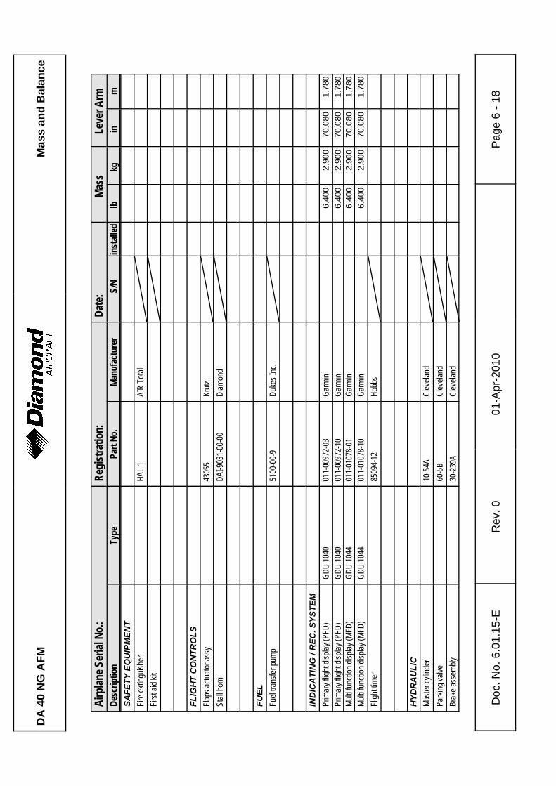
DA
40
NG
AFM
Mas
s an
d B
alan
ce
Airp
lane S
erial
No.
:Re
gist
ratio
n:Da
te:
Mass
Leve
r Arm
Desc
riptio
nTy
pePa
rt No
.Ma
nufa
ctur
erS/
Nin
stall
edlb
kgin
m
Doc
. No.
6.0
1.15
-ER
ev. 0
01-A
pr-2
010
Pag
e 6
- 18
SAFE
TY E
QU
IPM
ENT
Fire e
xting
uishe
rHA
L 1AI
R To
talFir
st aid
kit
FLIG
HT
CO
NTR
OLS
Flaps
actua
tor as
sy43
055
Krutz
Stall
horn
DAI-9
031-
00-0
0Di
amon
d
FUEL
Fuel
trans
fer pu
mp51
00-0
0-9
Duke
s Inc
.
IND
ICA
TIN
G /
REC
. SYS
TEM
Prim
ary f
light
displa
y (PF
D)GD
U 10
4001
1-00
972-
03Ga
rmin
6.40
02.
900
70.0
801.
780
Prim
ary f
light
displa
y (PF
D)GD
U 10
4001
1-00
972-
10Ga
rmin
6.40
02.
900
70.0
801.
780
Multi
functi
on di
splay
(MFD
)GD
U 10
4401
1-01
078-
01Ga
rmin
6.40
02.
900
70.0
801.
780
Multi
functi
on di
splay
(MFD
)GD
U 10
4401
1-01
078-
10Ga
rmin
6.40
02.
900
70.0
801.
780
Fligh
t time
r85
094-
12Ho
bbs
HYD
RA
ULI
CMa
ster c
ylind
er10
-54A
Clev
eland
Parki
ng va
lve60
-5B
Clev
eland
Brak
e ass
embly
30-2
39A
Clev
eland
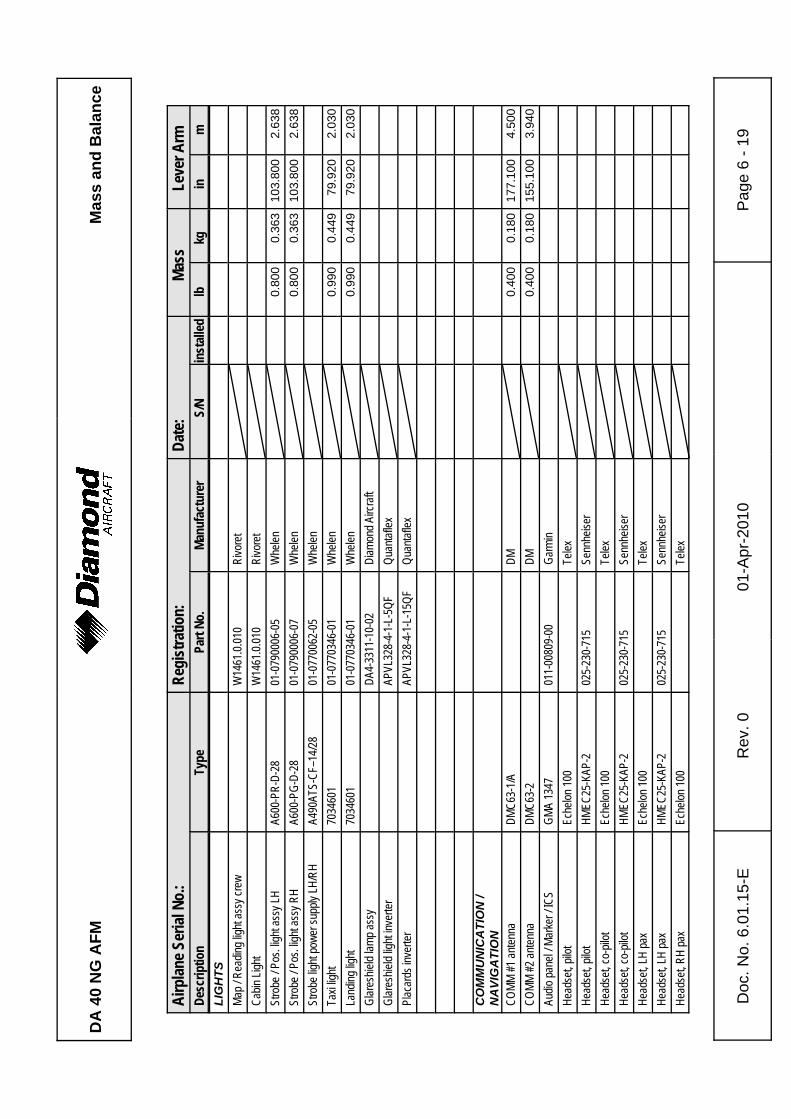
DA
40
NG
AFM
Mas
s an
d B
alan
ce
Airp
lane S
erial
No.
:Re
gist
ratio
n:Da
te:
Mass
Leve
r Arm
Desc
riptio
nTy
pePa
rt No
.Ma
nufa
ctur
erS/
Nin
stall
edlb
kgin
m
Doc
. No.
6.0
1.15
-ER
ev. 0
01-A
pr-2
010
Pag
e 6
- 19
LIG
HTS
Map /
Rea
ding l
ight a
ssy c
rew
W14
61.0.
010
Rivo
ret
Cabin
Ligh
tW
1461
.0.01
0Ri
vore
tSt
robe
/ Pos
. ligh
t ass
y LH
A600
-PR-
D-28
01-0
7900
06-0
5W
helen
0.80
00.
363
103.
800
2.63
8St
robe
/ Pos
. ligh
t ass
y RH
A600
-PG-
D-28
01-0
7900
06-0
7W
helen
0.80
00.
363
103.
800
2.63
8St
robe
light
powe
r sup
ply LH
/RH
A490
ATS-
CF–1
4/28
01-0
7700
62-0
5W
helen
Taxi
light
7034
601
01-0
7703
46-0
1W
helen
0.99
00.
449
79.9
202.
030
Land
ing lig
ht70
3460
101
-077
0346
-01
Whe
len0.
990
0.44
979
.920
2.03
0Gl
ares
hield
lamp a
ssy
DA4-
3311
-10-
02Di
amon
d Airc
raft
Glar
eshie
ld lig
ht inv
erter
APVL
328-
4-1-
L-5Q
FQu
antaf
lexPl
acar
ds in
verte
rAP
VL32
8-4-
1-L-
15QF
Quan
taflex
CO
MM
UN
ICA
TIO
N /
NA
VIG
ATI
ON
COMM
#1 an
tenna
DMC6
3-1/A
DM0.
400
0.18
017
7.10
04.
500
COMM
#2 an
tenna
DMC6
3-2
DM0.
400
0.18
015
5.10
03.
940
Audio
pane
l / Ma
rker /
ICS
GMA
1347
011-
0080
9-00
Garm
inHe
adse
t, pilo
tEc
helon
100
Telex
Head
set, p
ilot
HMEC
25-K
AP-2
025-
230-
715
Senn
heise
rHe
adse
t, co-
pilot
Eche
lon 10
0Te
lexHe
adse
t, co-
pilot
HMEC
25-K
AP-2
025-
230-
715
Senn
heise
rHe
adse
t, LH
pax
Eche
lon 10
0Te
lexHe
adse
t, LH
pax
HMEC
25-K
AP-2
025-
230-
715
Senn
heise
rHe
adse
t, RH
pax
Eche
lon 10
0Te
lex
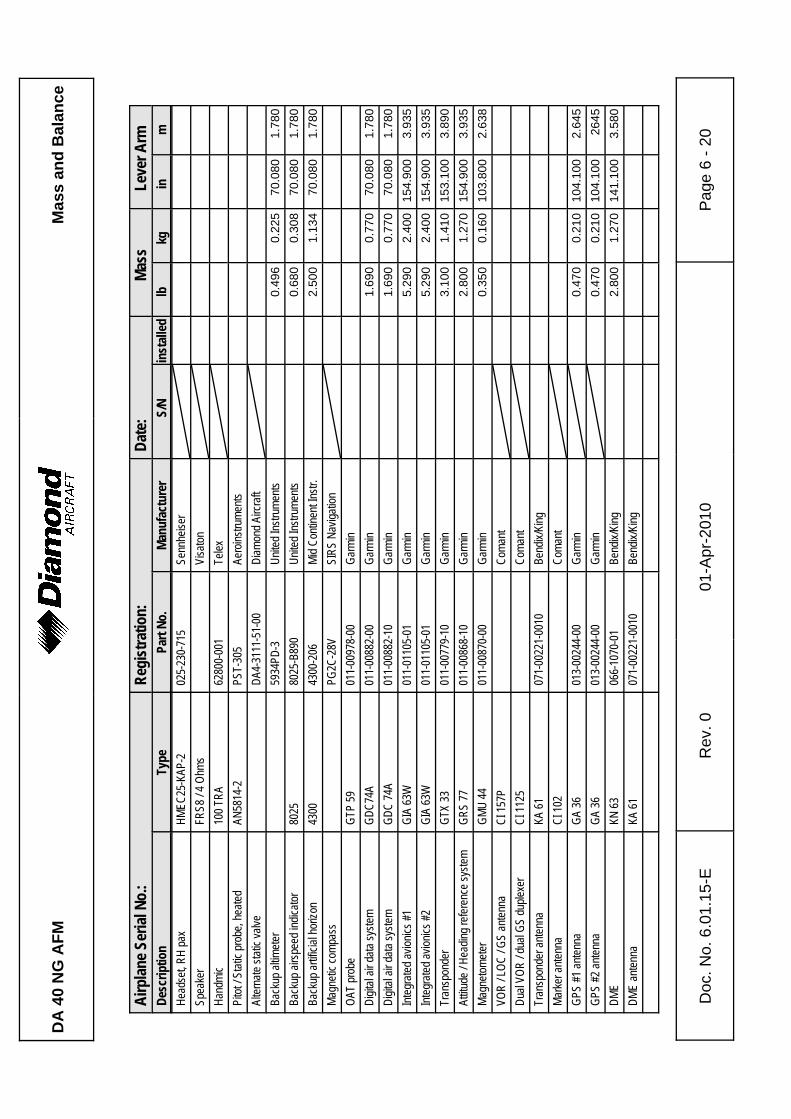
DA
40
NG
AFM
Mas
s an
d B
alan
ce
Airp
lane S
erial
No.
:Re
gist
ratio
n:Da
te:
Mass
Leve
r Arm
Desc
riptio
nTy
pePa
rt No
.Ma
nufa
ctur
erS/
Nin
stall
edlb
kgin
m
Doc
. No.
6.0
1.15
-ER
ev. 0
01-A
pr-2
010
Pag
e 6
- 20
Head
set, R
H pa
xHM
EC25
-KAP
-202
5-23
0-71
5Se
nnhe
iser
Spea
ker
FRS8
/ 4 O
hms
Visa
tonHa
ndmi
c10
0 TRA
6280
0-00
1Te
lexPi
tot / S
tatic
prob
e, he
ated
AN58
14-2
PST-
305
Aero
instru
ments
Alter
nate
static
valve
DA4-
3111
-51-
00Di
amon
d Airc
raft
Back
up al
timete
r59
34PD
-3Un
ited I
nstru
ments
0.49
60.
225
70.0
801.
780
Back
up ai
rspee
d ind
icator
8025
8025
-B89
0Un
ited I
nstru
ments
0.68
00.
308
70.0
801.
780
Back
up ar
tificia
l hor
izon
4300
4300
-206
Mid C
ontin
ent In
str.
2.50
01.
134
70.0
801.
780
Magn
etic c
ompa
ssPG
2C-2
8VSI
RS N
aviga
tion
OAT
prob
eGT
P 59
011-
0097
8-00
Garm
inDi
gital
air da
ta sy
stem
GDC7
4A01
1-00
882-
00Ga
rmin
1.69
00.
770
70.0
801.
780
Digit
al air
data
syste
mGD
C 74
A01
1-00
882-
10Ga
rmin
1.69
00.
770
70.0
801.
780
Integ
rated
avion
ics #1
GIA
63W
011-
0110
5-01
Garm
in5.
290
2.40
015
4.90
03.
935
Integ
rated
avion
ics #2
GIA
63W
011-
0110
5-01
Garm
in5.
290
2.40
015
4.90
03.
935
Tran
spon
der
GTX
3301
1-00
779-
10Ga
rmin
3.10
01.
410
153.
100
3.89
0At
titude
/ Hea
ding r
efere
nce s
ystem
GRS
7701
1-00
868-
10Ga
rmin
2.80
01.
270
154.
900
3.93
5Ma
gneto
meter
GMU
4401
1-00
870-
00Ga
rmin
0.35
00.
160
103.
800
2.63
8VO
R / L
OC / G
S an
tenna
CI 15
7PCo
mant
Dual
VOR
/ dua
l GS
duple
xer
CI 11
25Co
mant
Tran
spon
der a
ntenn
aKA
6107
1-00
221-
0010
Bend
ix/Ki
ngMa
rker a
ntenn
aCI
102
Coma
ntGP
S #1
anten
naGA
3601
3-00
244-
00Ga
rmin
0.47
00.
210
104.
100
2.64
5GP
S #2
anten
naGA
3601
3-00
244-
00Ga
rmin
0.47
00.
210
104.
100
2645
DME
KN 63
066-
1070
-01
Bend
ix/Ki
ng2.
800
1.27
014
1.10
03.
580
DME
anten
naKA
6107
1-00
221-
0010
Bend
ix/Ki
ng
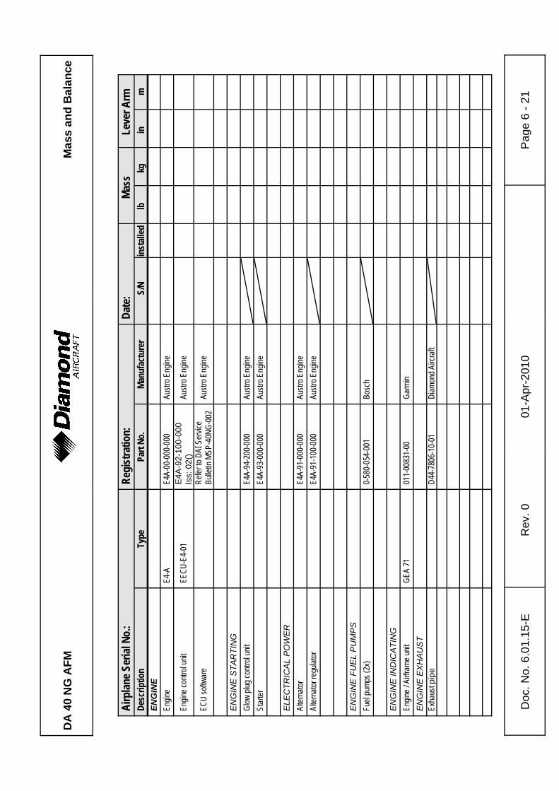
DA
40
NG
AFM
Mas
s an
d B
alan
ce
Airp
lane S
erial
No.
:Re
gist
ratio
n:Da
te:
Mass
Leve
r Arm
Desc
riptio
nTy
pePa
rt No
.Ma
nufa
ctur
erS/
Nin
stall
edlb
kgin
m
Doc
. No.
6.0
1.15
-ER
ev. 0
01-A
pr-2
010
Pag
e 6
- 21
ENG
INE
Engin
eE4
-AE4
A-00
-000
-000
Austr
o Eng
ine
Engin
e con
trol u
nitEE
CU-E
4-01
E4A-
92-1
00-0
00Is
s: 0
2()
Austr
o Eng
ine
ECU
softw
are
Refer
to D
AI S
ervic
eBu
lletin
MSP
-40N
G-00
2Au
stro E
ngine
EN
GIN
E S
TAR
TIN
GGl
ow pl
ug co
ntrol
unit
E4A-
94-2
00-0
00Au
stro E
ngine
Star
terE4
A-93
-000
-000
Austr
o Eng
ine
ELE
CTR
ICA
L P
OW
ER
Alter
nator
E4A-
91-0
00-0
00Au
stro E
ngine
Alter
nator
regu
lator
E4A-
91-1
00-0
00Au
stro E
ngine
EN
GIN
E F
UE
L P
UM
PS
Fuel
pump
s (2x
)0-
580-
054-
001
Bosc
h
EN
GIN
E IN
DIC
ATI
NG
Engin
e / A
irfram
e unit
GEA
7101
1-00
831-
00Ga
rmin
EN
GIN
E E
XH
AU
ST
Exha
ust p
ipe
D44-
7806
-10-
01Di
amon
d Airc
raft
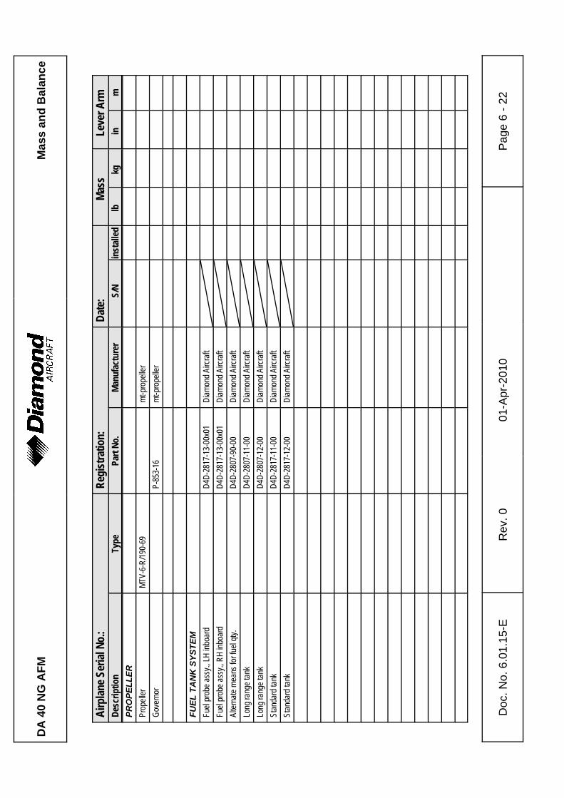
DA
40
NG
AFM
Mas
s an
d B
alan
ce
Airp
lane S
erial
No.
:Re
gist
ratio
n:Da
te:
Mass
Leve
r Arm
Desc
riptio
nTy
pePa
rt No
.Ma
nufa
ctur
erS/
Nin
stall
edlb
kgin
m
Doc
. No.
6.0
1.15
-ER
ev. 0
01-A
pr-2
010
Pag
e 6
- 22
PRO
PELL
ERPr
opell
er
MTV-
6-R/
190-
69mt
-pro
pelle
rGo
vern
or
P-85
3-16
mt-p
rope
ller
FUEL
TA
NK
SYS
TEM
Fuel
prob
e ass
y., LH
inbo
ard
D4D-
2817
-13-
00x0
1Di
amon
d Airc
raft
Fuel
prob
e ass
y., R
H inb
oard
D4D-
2817
-13-
00x0
1Di
amon
d Airc
raft
Alter
nate
mean
s for
fuel
qty.
D4D-
2807
-90-
00
Diam
ond A
ircra
ftLo
ng ra
nge t
ank
D4D-
2807
-11-
00Di
amon
d Airc
raft
Long
rang
e tan
kD4
D-28
07-1
2-00
Diam
ond A
ircra
ftSt
anda
rd ta
nkD4
D-28
17-1
1-00
Diam
ond A
ircra
ftSt
anda
rd ta
nkD4
D-28
17-1
2-00
Diam
ond A
ircra
ft

DA
40
NG
AFM
Mas
s an
d B
alan
ce
Airp
lane S
erial
No.
:Re
gist
ratio
n:Da
te:
Mass
Leve
r Arm
Desc
riptio
nTy
pePa
rt No
.Ma
nufa
ctur
erS/
Nin
stall
edlb
kgin
m
Doc
. No.
6.0
1.15
-ER
ev. 0
01-A
pr-2
010
Pag
e 6
- 23
AIR
PLA
NE
FLIG
HT
MA
NU
AL
Doc.
No. 6
.01.15
-EDi
amon
d Airc
raft
Plac
e: __
____
____
____
____
____
_Da
te: __
____
____
____
____
____
____
_Si
gnatu
re: _
____
____
____
____
____
____
____
_
DA
40
NG
AFM
Mas
s an
d B
alan
ce
Doc
. No.
6.0
1.15
-ER
ev. 0
01-A
pr-2
010
Pag
e 6
- 24
Inte
ntio
nally
left
blan
k.
DA 40 NG AFMAirplane
Description
Doc. # 6.01.15-E Rev. 0 01-Apr-2010 Page 7 - 1
CHAPTER 7DESCRIPTION OF THE AIRPLANE
AND ITS SYSTEMS
Page
7.1 INTRODUCTION . . . . . . . . . . . . . . . . . . . . . . . . . . . . . . . . . . . . . . . 7-37.2 AIRFRAME . . . . . . . . . . . . . . . . . . . . . . . . . . . . . . . . . . . . . . . . . . . 7-37.3 FLIGHT CONTROLS . . . . . . . . . . . . . . . . . . . . . . . . . . . . . . . . . . . . 7-47.4 INSTRUMENT PANEL . . . . . . . . . . . . . . . . . . . . . . . . . . . . . . . . . . 7-97.5 LANDING GEAR . . . . . . . . . . . . . . . . . . . . . . . . . . . . . . . . . . . . . . 7-147.6 SEATS AND SAFETY HARNESSES . . . . . . . . . . . . . . . . . . . . . . 7-167.7 BAGGAGE COMPARTMENT . . . . . . . . . . . . . . . . . . . . . . . . . . . . 7-167.8 CANOPY, REAR DOOR, AND CABIN INTERIOR . . . . . . . . . . . . 7-177.9 POWER PLANT . . . . . . . . . . . . . . . . . . . . . . . . . . . . . . . . . . . . . . 7-19
7.9.1 ENGINE, GENERAL . . . . . . . . . . . . . . . . . . . . . . . . . . . . . . 7-197.9.2 OPERATING CONTROLS . . . . . . . . . . . . . . . . . . . . . . . . . 7-207.9.3 PROPELLER . . . . . . . . . . . . . . . . . . . . . . . . . . . . . . . . . . . . 7-237.9.4 ENGINE INSTRUMENTS . . . . . . . . . . . . . . . . . . . . . . . . . . 7-257.9.5 FUEL SYSTEM . . . . . . . . . . . . . . . . . . . . . . . . . . . . . . . . . . 7-277.9.6 COOLING SYSTEM . . . . . . . . . . . . . . . . . . . . . . . . . . . . . . 7-357.9.7 TURBO CHARGER SYSTEM . . . . . . . . . . . . . . . . . . . . . . . 7-367.9.8 OIL SYSTEMS . . . . . . . . . . . . . . . . . . . . . . . . . . . . . . . . . . 7-37
7.10 ELECTRICAL SYSTEM . . . . . . . . . . . . . . . . . . . . . . . . . . . . . . . . 7-387.10.1 GENERAL . . . . . . . . . . . . . . . . . . . . . . . . . . . . . . . . . . . . . 7-397.10.2 ENGINE CONTROL UNIT / ECU . . . . . . . . . . . . . . . . . . . 7-467.10.3 WARNING, CAUTION AND ADVISORY MESSAGES . . . 7-48
7.11 PITOT-STATIC SYSTEM . . . . . . . . . . . . . . . . . . . . . . . . . . . . . . . 7-507.12 STALL WARNING SYSTEM . . . . . . . . . . . . . . . . . . . . . . . . . . . . . 7-50
AirplaneDescription
DA 40 NG AFM
Page 7 - 2 Rev. 0 01-Apr-2010 Doc. # 6.01.15-E
7.13 GARMIN G1000 INTEGRATED AVIONICS SYSTEM . . . . . . . . . 7-517.13.1 GENERAL . . . . . . . . . . . . . . . . . . . . . . . . . . . . . . . . . . . . . 7-517.13.2 PRIMARY FLIGHT DISPLAY (PFD) . . . . . . . . . . . . . . . . . 7-517.13.3 MULTI-FUNCTION DISPLAY (MFD) . . . . . . . . . . . . . . . . . 7-537.13.4 AUDIO PANEL . . . . . . . . . . . . . . . . . . . . . . . . . . . . . . . . . 7-547.13.5 ATTITUDE AND HEADING REFERENCE SYSTEM (AHRS)
. . . . . . . . . . . . . . . . . . . . . . . . . . . . . . . . . . . . . . . . . . . . . . 7-547.13.6 AIR DATA COMPUTER (ADC) . . . . . . . . . . . . . . . . . . . . . 7-54
7.14 AVIONICS . . . . . . . . . . . . . . . . . . . . . . . . . . . . . . . . . . . . . . . . . . . 7-557.14.1 AUTOPILOT SYSTEM . . . . . . . . . . . . . . . . . . . . . . . . . . . 7-557.14.2 AUTOMATIC FLIGHT CONTROL SYSTEM ANNUNCIATIONS AND
ALERTS . . . . . . . . . . . . . . . . . . . . . . . . . . . . . . . . . . . . . . . 7-60
DA 40 NG AFMAirplane
Description
Doc. # 6.01.15-E Rev. 0 01-Apr-2010 Page 7 - 3
7.1 INTRODUCTION
Chapter 7 contains a description of the airplane and its systems, together with operatinginstructions.
For details about optional equipment see Chapter 9.
7.2 AIRFRAME
Fuselage
The GFRP fuselage is of semi monocoque molded construction. The fire protection onthe firewall is of a special fire-resistant matting, which is covered on the engine side bystainless steel cladding. The two main bulkheads are GFRP/CFRP items.
Wings
The wings have a front and rear spar; each wing has a top shell and a bottom shell - a'fail-safe' concept. The wings, as well as the ailerons and flaps, are made of GFRP/CFRP,and are principally of sandwich construction. An aluminum fuel tank is installed in eachof the wings.
Empennage
The airplane has a 'T' tail of GFRP semi monocoque construction. Both the stabilizershave twin spars and a skin with no sandwich. Rudder and elevator are of sandwichconstruction.
AirplaneDescription
DA 40 NG AFM
Page 7 - 4 Rev. 0 01-Apr-2010 Doc. # 6.01.15-E
7.3 FLIGHT CONTROLS
The ailerons, elevator and wing flaps are operated through control rods, while the rudderis controlled by cables. The flaps are electrically operated. Elevator forces can be balancedby a trim tab on the elevator, which is operated by a Bowden cable.
Ailerons
Construction: GFRP/CFRP composite sandwich.
Hinges: There are 4 hinges, which are hinge pins mounted in an aluminumbracket. They are secured in position by a roll pin. The absence of thisroll pin can lead to the loss of the hinge pin and a consequent loss of flightsafety.
Operation: A rod-end bearing is screwed into a steel push rod and locked by meansof a jam nut which has locking varnish applied to it. Damage to thisvarnish can indicate a twisting and thus a change to the adjustment. Theconnection between the rod-end bearing and the control horn is a bolt,the nut of which is likewise sealed with locking varnish.
The aluminum control horn is attached to the aileron with 3 screws.
DA 40 NG AFMAirplane
Description
Doc. # 6.01.15-E Rev. 0 01-Apr-2010 Page 7 - 5
Flaps
Construction: GFRP/CFRP composite sandwich.
Hinges: There are 6 hinges, which are hinge pins mounted in an aluminumbracket. They are secured in position by a roll pin. The absence of thisroll pin can lead to the loss of the hinge pin and a consequent loss of flightsafety. Another aluminum fitting is located at the fuselage and is attachedto a torsion tube. The torsion tube is located in the fuselage, creating aconnection between the left and right flaps.
Operation: A rod-end bearing is screwed into a steel push rod and locked by meansof a jam nut which has locking varnish applied to it. Damage to thisvarnish can indicate a twisting and thus a change to the adjustment. Theconnection between the rod-end bearing and the control horn is a bolt,the nut of which is likewise sealed with locking varnish.
The flap control horn is attached to the flap with 3 screws.
The flaps are driven by an electric motor and have 3 settings:
- Cruise (UP), totally retracted
- Take-off (T/O), and
- Landing (LDG).
AirplaneDescription
DA 40 NG AFM
Page 7 - 6 Rev. 0 01-Apr-2010 Doc. # 6.01.15-E
The flaps are operated by means of a 3-position flap selector switch on the instrumentpanel. The positions of the switch correspond to the positions of the flaps, the cruiseposition of the switch being at the top. If the switch is moved to another position, the flapscontinue to travel automatically until they have reached the position selected on the switch.The UP and LDG positions are additionally protected by a limit switch to guard againstover-running the end positions.
The electrical flap drive has an automatic circuit breaker which can also be operatedmanually.
Flap Position Indicator:
The current flap position is indicated by means of three lights beside the flap selectorswitch.
When the upper light (green) is illuminated, the flaps are in the cruise position (UP);
when the center light (white) is illuminated, the flaps are in take-off position (T/O);
when the lower light (white) is illuminated, the flaps are in landing position (LDG).
When two lights are illuminated simultaneously, the flaps are between the two indicatedpositions. This is the case only when the flaps are traveling.
DA 40 NG AFMAirplane
Description
Doc. # 6.01.15-E Rev. 0 01-Apr-2010 Page 7 - 7
Elevator
Construction: GFRP sandwich.
Hinges: 5 hinges.
Operation: Steel push-rods;
Two of the bellcrank bearings are accessible to visual inspection nextto the lower hinge of the rudder. The elevator horn and its bearing, aswell as the connection to the push-rod, can be visually inspected at theupper end of the rudder.
Rudder
Construction: GFRP sandwich.
Hinges: Upper hinge: One bolt.
Lower hinge: Bearing bracket including rudder stops, held by 4 screwsto the rear web of the vertical stabilizer. The mating parton the rudder is a bracket which is attached to the rudderby 2 bolts. The bolts and nuts are accessible to visualinspection.
Operation: Steel cables, the eyes of which are connected to the bolts on the bracket.
AirplaneDescription
DA 40 NG AFM
Page 7 - 8 Rev. 0 01-Apr-2010 Doc. # 6.01.15-E
Elevator Trim
The trim control is a black wheel in the center console to the rear of the power lever. Toguard against over-rotating, the trim wheel incorporates a friction device. A mark on thewheel shows the take-off (T/O) position.
Turn wheel to the front = nose down
Turn wheel to the rear = nose up
Pedal Adjustment
NOTEThe pedals may only be adjusted on the ground!
The pedals are unlocked by pulling the black handle which is located behind the rearattachment.
Forward Adjustment:
Whilst keeping the handle pulled, push the pedals forward with your feet. Release thehandle and allow the pedals to lock into place.
Rearward Adjustment:
Using the unlocking handle, pull the pedals back to the desired position. Release thehandle and push the pedals forward with your feet until they lock into place.
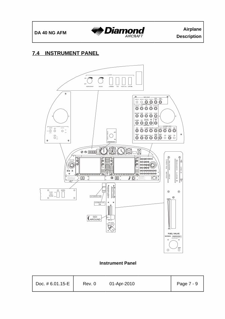
DA 40 NG AFMAirplane
Description
Doc. # 6.01.15-E Rev. 0 01-Apr-2010 Page 7 - 9
7.4 INSTRUMENT PANEL
Instrument Panel
ALTERNATE AIR
ALTERNATE AIRON
ALTERNATE AIR
OFF
EMERGENCY
ON
HORIZON
OFF
EM ER GE N CY
ON
HORIZON
Ma n ou v er i ng sp e ed : = 111 K I A S ( a b ov e 1 0 36 up to 1 20 0 k g / a bo ve 2 28 4 u p t o 26 4 6 l b)
= 94 K IA S ( 7 8 0 t o 1 0 36 kg / 1 7 20 t o 2 28 4 lb )T hi s a i r pl a ne ma y o nl y b e op era te d i n a cc or d a nc e w i t h t h e A i r pl a ne F li g htMa n ua l . I t ca n b e o p era ted in t he "N o r ma l" a n d "Ut i li t y" c at e go r i es inn on - i ci ng co n di t io n s. P r ov id e d t h at na t i on a l o pe r a ti o na l r e q ui r e me nt sa r e m et an d th e ap pro p r ia t e e q uip me nt i s i ns ta l le d , t h i s ai r p la n e i s a p-p r ov ed for t h e fo ll ow in g k i nd s o f o p er a t io n : d a y V F R , ni gh t V F R a n dIF R. A l l a er o b at i cs ma n eu ve r s i n cl ud ing sp i nn i ng ar e pr o h ib i te d . F o rfur th e r o p er a t io n al li m ita tio ns ref e r t o t he A ir p l an e F l i gh t M a nu al .No sm ok in g
V
VA
A
Limitations for GFC 700 Aut opilot System:D o n o t u s e A P i f “ A l t er n ate S ta t i c ” i s o p e n .
C o n d u c t A P a n d t r im c h e c k p ri o r to e a ch f l i g ht ( se e A F M ) .A u t o p i lo t O F F d u r i n g t ak e - o f f a n d la n d i n g .M a xi m u m s pe e d f o r a u t o p il o t o p e r a tio n i s 16 5 K IA S .M i n im u m s pe e d f o r a u to p il o t o p e ra t io n i s 7 0 K IA S .M i n im u m a l ti t u d e f o r a u t op i l o t o pe r ati o n :C r u is e , C l im b , D e s ce n t a n d Ma n e u v e ri n g: 8 0 0 f e e t A G LA p p r o a c h : 2 0 0 f e e t A G L
Ess Busnot fornormal
operationSee AFM
ECU A
FUELPUMPS
ON
OFF
ECUTEST
MASTER
ENGINE
ECU B
VOTER
AUTO
ON
OFF
ON
ESSBUS
AVIONICMASTER
OFF
Ess Busnot fornormal
operationSee AFM
EECU B
EECU BUS
MAIN BUSAVIONICS BUS
EECU A
GPS/NAV1
MASTERCONTROL
FUELPUMP A
COM1AHRS ADCHORIZON
EECU A EECU BFUEL
PUMP B
ESSENTIAL BUS
20
3
5
5
60
3
5
3
30
25
5
5
5
5 5
3
2
5
5
5
5
10
5
5
2
5
5
5
10
30
5
3
20 20
GO-AROUND
PARKING
BRAKE
RELEASE
LOCK
DEFROST
CABIN
ON
OFF
NORMAL
OFF
EMERGENCYCAU TION interm ittent useonly (s ee AF M)
FUEL VALVE
100%
0%
FLOOR
PARKI
NG
BRAKE
RELEASE
LOCK
DEFROST
CABI
N
ON
OF F
NORMAL
OFF
EMERGENCYC AU TION inte rm ittent useo nly ( see AFM)
FUEL VALVE
100%
0%
FLOOR
GO-AROUND
FUEL
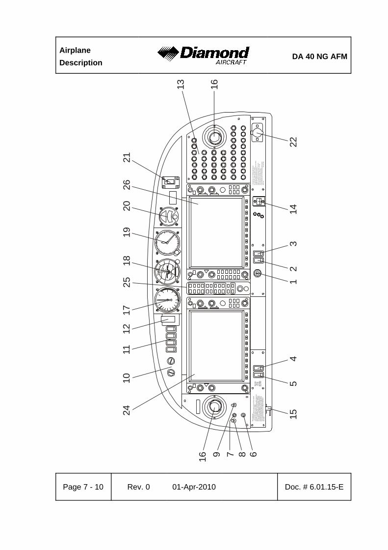
AirplaneDescription
DA 40 NG AFM
Page 7 - 10 Rev. 0 01-Apr-2010 Doc. # 6.01.15-E
Man
ouve
ring
spee
d:
=111
KIA
S (a
bov
e 1
036
up to
120
0 kg
/ ab
ove
2284
up
to 2
646
lb)
=94
KIA
S (7
80 to
103
6 kg
/ 1
720
to 2
284l
b)T
his a
irplan
e m
ay o
nly b
e o
pera
ted
in a
ccor
danc
e w
ith th
e Ai
rpla
ne F
light
Man
ual.
It c
an b
e op
erat
ed in
the
"No
rmal
" and
"Ut
ility
" cat
egor
ies
inno
n-ic
ing
cond
ition
s. P
rovi
ded
that
nat
iona
l ope
ratio
nal r
equi
rem
ents
are
met
and
the
appr
opria
te e
quip
men
t is
inst
alle
d, th
is a
irpla
ne is
ap-
prov
ed fo
r the
follo
win
g kin
ds o
f op
erat
ion:
day
VF
R, n
ight
VFR
and
IFR.
All a
erob
atic
s man
euve
rs in
cludi
ng s
pinn
ing
are
proh
ibite
d. F
orfu
rthe
r ope
ratio
nal
limita
tions
refe
r to
the
Airp
lane
Flig
ht M
anu
al.N
o sm
okin
g
V V
A A
Lim
itatio
ns fo
r GFC
700
Aut
opilo
t Sys
tem
:D
o n
ot u
se
AP
if “A
ltern
ate
Sta
tic” i
s o
pen.
Co
ndu
ct A
P a
nd
trim
che
ck p
rior
to e
ach
flig
ht (
see
AF
M).
Aut
opilo
t OF
F d
urin
g ta
ke-o
ff a
nd l
and
ing.
Max
imum
spe
ed fo
r au
top
ilot o
pera
tion
is 1
65
KIA
S.
Min
imum
spe
ed f
or a
uto
pilo
t ope
ratio
n is
70
KIAS
.M
inim
um a
ltitu
de fo
r au
top
ilot o
pera
tion:
Cru
ise
, Clim
b, D
esc
ent a
nd M
ane
uve
ring
: 80
0 fe
et A
GL
App
roac
h:
200
fee
t AG
L
Ess
Bus
not f
orno
rmal
ope
ratio
nS
ee A
FM
2410
1112
1725
1819
2026
21
13 16
2214
32
14
515
687916
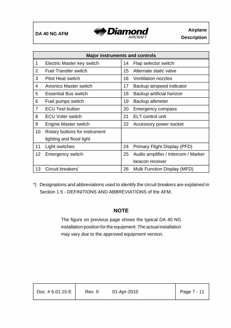
DA 40 NG AFMAirplane
Description
Doc. # 6.01.15-E Rev. 0 01-Apr-2010 Page 7 - 11
Major instruments and controls1 Electric Master key switch 14 Flap selector switch2 Fuel Transfer switch 15 Alternate static valve3 Pitot Heat switch 16 Ventilation nozzles4 Avionics Master switch 17 Backup airspeed indicator5 Essential Bus switch 18 Backup artificial horizon6 Fuel pumps switch 19 Backup altimeter7 ECU Test button 20 Emergency compass8 ECU Voter switch 21 ELT control unit9 Engine Master switch 22 Accessory power socket 10 Rotary buttons for instrument
lighting and flood light11 Light switches 24 Primary Flight Display (PFD)12 Emergency switch 25 Audio amplifier / Intercom / Marker
beacon receiver13 Circuit breakers* 26 Multi Function Display (MFD)
*) Designations and abbreviations used to identify the circuit breakers are explained inSection 1.5 - DEFINITIONS AND ABBREVIATIONS of the AFM.
NOTEThe figure on previous page shows the typical DA 40 NGinstallation position for the equipment. The actual installationmay vary due to the approved equipment version.
AirplaneDescription
DA 40 NG AFM
Page 7 - 12 Rev. 0 01-Apr-2010 Doc. # 6.01.15-E
Cockpit Ventilation
Ventilation in the front is provided by the movable ventilation over nozzles (16) in theinstrument panel. Furthermore there are spherical nozzles in the roll bar on the left andright side next to the front seats as well as on the central console above the passengers’heads. The spherical nozzles are opened and closed by twisting.
Unconditioned ambient air is supplied to the interior through an inlet on the bottom surfaceof the left wing. To increase cabin temperatures when operating at low outside airtemperatures, a ventilation inlet baffle may be installed at the inlet. With the baffle installed,the rear cabin ventilation nozzles on the left and right hand side and in the central consoleabove the passengers' heads will be inoperative.
The ventilation inlet baffle consists of a metal plate with rubber edging and is attachedto the bottom LH wing by a camloc.
Heating
Heating is operated using two levers located on the small center console under theinstrument panel.
Right lever: up = heating ONdown = heating OFF
Central lever (air distribution lever):
up = airflow to canopy (DEFROST)down = airflow to floor (FLOOR)
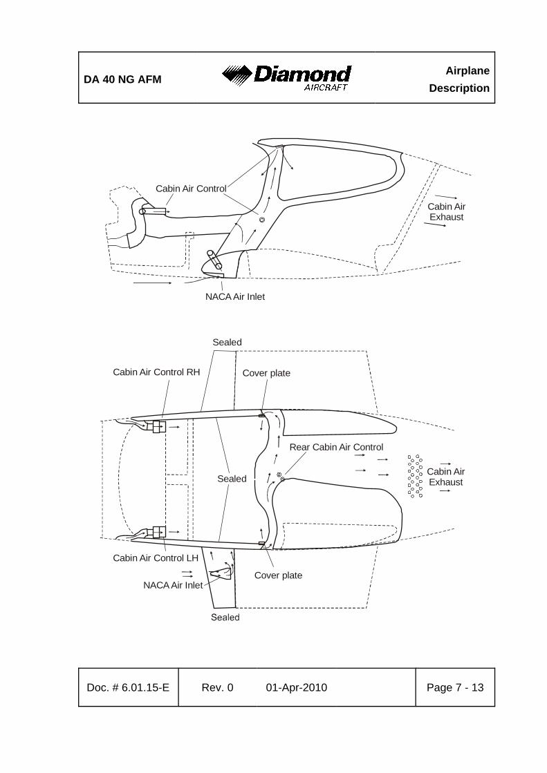
DA 40 NG AFMAirplane
Description
Doc. # 6.01.15-E Rev. 0 01-Apr-2010 Page 7 - 13
NACA Air Inlet
NACA Air Inlet
Cabin Air Control
Cabin Air Control RH
Rear Cabin Air Control
Cabin Air Control LH
Cabin AirExhaust
Cabin AirExhaust
Sealed
Cover plate
Cover plate
Sealed
AirplaneDescription
DA 40 NG AFM
Page 7 - 14 Rev. 0 01-Apr-2010 Doc. # 6.01.15-E
7.5 LANDING GEAR
The landing gear consists of a main landing gear of spring steel struts, and a free-casteringnose wheel which is spring-loaded by an elastomer package.
The wheel fairings are removable. When flying without wheel fairings, it should be notedthat there is a reduction in some areas of performance (see Chapter 5).
Wheel Brakes
Hydraulically operating disk brakes act on the wheels of the main landing gear. The wheelbrakes are individually operated by means of toe pedals.
Parking Brake
The lever is located on the small center console under the instrument panel, and is inthe upper position when the brakes are released. To operate the parking brake pull thelever downwards until it catches. Brake pressure is built up by multiple operation of thetoe brake pedals, and is maintained until the parking brake is released. To release, thelever is pushed upwards.

DA 40 NG AFMAirplane
Description
Doc. # 6.01.15-E Rev. 0 01-Apr-2010 Page 7 - 15
MasterCylinders
VentedPlug
Pilot’s Pedals
MasterCylinders
Co-Pilot’s Pedals
VentedPlug
Brake FluidReservoir
Fluid Level
LOCK
PARKING BRAKE
RELEASEFlexible Hose
Parking Brake Valve
Brake Disc
Brake Caliper
Rigid Pipe
Pressure Plate
Back Plate
Rigid Pipe Brake Disc
Pressure Plate
Brake CaliperBack Plate
Flexible Hose
Flexible HoseFlexible Hose
Hydraulic System Schematic

AirplaneDescription
DA 40 NG AFM
Page 7 - 16 Rev. 0 01-Apr-2010 Doc. # 6.01.15-E
7.6 SEATS AND SAFETY HARNESSES
To increase passive safety, the seats are constructed using a carbon fiber/Kevlar hybridmaterial and GFRP. The seats are removable to allow the maintenance and inspectionof the underlying controls. Covers on the control sticks prevent loose objects from fallinginto the area of the controls.
The seats have removable furnishings and are equipped with energy-absorbing foamelements.
The seats are fitted with three-part safety harnesses. The harnesses are fastened byinserting the end of the belts in the belt lock, and are opened by pressing the red releaseon the belt lock.
The backs of the rear seats can be laid forward after pulling upwards on the knob of thelocking bolt.
7.7 BAGGAGE COMPARTMENT
The baggage compartment is behind the seat backs of the rear seats. Without a baggagenet, no baggage may be loaded.
As options, a baggage tube or a baggage extension (OÄM 164) may be installed.
DA 40 NG AFMAirplane
Description
Doc. # 6.01.15-E Rev. 0 01-Apr-2010 Page 7 - 17
7.8 CANOPY, REAR DOOR, AND CABIN INTERIOR
Front Canopy
The front canopy is closed by pulling down on the canopy frame and locking it with thehandle on the left hand side of the canopy frame. On locking, steel bolts catch into matingholes in polyethylene blocks.
"Cooling gap" position: A second setting allows the bolts to lock in, leaving a gap underthe forward canopy.
The canopy can be key-locked by a locking mechanism on the left side near the canopylever by turning the key clockwise. The closed and locked canopy can be opened frominside by pulling the lever inside the opening handle.
WARNINGThe airplane may be operated with the front canopy in the"cooling gap" position on the ground only. Before take-off thefront canopy must be completely closed and latched, but notkey-locked.
Do not key-lock the front canopy before flight to assureemergency evacuation from outside.
A window on the left and right hand side of the canopy can be opened for additionalventilation or as emergency windows.
AirplaneDescription
DA 40 NG AFM
Page 7 - 18 Rev. 0 01-Apr-2010 Doc. # 6.01.15-E
Rear Door
The rear door is closed in the same way, by pulling down on the frame and locking it withthe handle. A gas pressure damper prevents the door from dropping; in strong winds theassembly must be held. The rear door is protected against unintentional opening by anadditional lever.
The door can be locked by a locking mechanism on the left side near the door openinglever by turning the key clockwise. The closed and locked door can be opened from insideby pulling the lever inside the opening handle. For a better handling an additional handleis mounted.
WARNINGBefore starting the engine the door must be closed andlatched, but not key-locked.
Do not key-lock the door before flight in order to assureemergency evacuation from outside.
DA 40 NG AFMAirplane
Description
Doc. # 6.01.15-E Rev. 0 01-Apr-2010 Page 7 - 19
7.9 POWER PLANT
7.9.1 ENGINE, GENERAL
The installed Austro Engine E4-A engine has the following specifications:
- Liquid-cooled four-cylinder four-stroke engine with wet sump lubrication
- Inline construction
- Common rail direct injection
- Propeller speed reducing gear 1:1.69
- Digital engine control with integrated propeller governor (using the gearbox oilsystem)
- Turbo charger with intercooler
Displacement:
Max. power: 123.5 kW (165.6 DIN-HP) at 2300 RPMat sea level and ISA
Max. continuous power: 114.0 kW (152.8 DIN-HP) at 2100 RPMat sea level and ISA
The indications for monitoring important engine parameters during operation are integratedwithin the Garmin G1000 display. The engine can only be operated with the ENGINEMASTER switch ON. The engine has an EECU (Electrical Engine Control Unit) whichreceives its electrical power from the generator when the engine is running. When theengine is not running, the ECU receives its electrical power from the battery.
AirplaneDescription
DA 40 NG AFM
Page 7 - 20 Rev. 0 01-Apr-2010 Doc. # 6.01.15-E
7.9.2 OPERATING CONTROLS
Power Lever
The engine performance is controlled by the power lever, situated on the large centerconsole. 'Front' and 'rear' are defined in relation to the direction of flight.
This lever is used to set the desired engine power LOAD (%)
Lever forward (MAX) = Full power
Lever to rear (IDLE) = Idle
The ECU controls manifold pressure, injected fuel quantity and propeller speed accordingto the desired engine power preselected with the power lever.
The propeller governor is attached to the top rear side of the gearbox and uses gearboxoil for propeller pitch regulation. Following a loss of oil pressure the propeller blades goto the low pitch stop (maximum RPM), thus allowing continuation of the flight accordingto 3.5.7 - DEFECTIVE RPM REGULATING SYSTEM.
DA 40 NG AFMAirplane
Description
Doc. # 6.01.15-E Rev. 0 01-Apr-2010 Page 7 - 21
ELECTRIC MASTER
The key can be switched into three positions:
OFF Disconnecting battery power.
ON Connecting battery power to the power distribution system.
START Starting the engine.
ENGINE MASTER
The engine can only be cranked with the ENGINE MASTER switched to ON. To shut downthe engine the ENGINE MASTER is switched to OFF.
ECU VOTER
For normal operation the switch is set to AUTO. The engine is controlled by either ECU Aor ECU B. In case of a failure of the active electrical engine control unit (ECU) there isan automatic switch-over to the other ECU. If the automatic switch over fails, switch overcan be done manually by switching to ECU A or ECU B. This procedure should only beapplied in an emergency.
AirplaneDescription
DA 40 NG AFM
Page 7 - 22 Rev. 0 01-Apr-2010 Doc. # 6.01.15-E
ECU TEST
Power Lever at IDLE:
By pushing and holding the button until the end of the procedure, the self-test of eachengine control unit is started. The procedure is possible on the ground only. Otherwisethe test will not start. During the procedure the ECU performs a switch from ECU Ato ECU B or ECU B to ECU A, whichever is active at the moment, with the propellercycling. The propeller RPM is monitored automatically by the ECU. When switchingfrom one ECU to the other, a slight shake of the engine may occur. Finally the ECUswitches back. After that both caution lights must extinguish and the engine must runwithout a change.
Alternate Air
In the event of power loss because of icing or blockage of the air filter, there is thepossibility of drawing air from the engine compartment. The ALTERNATE AIR operatinglever is located under the instrument panel on the left side of the center console. To openthe alternate air source the lever is pulled to the rear. The alternate air source is closed,with the lever being in the forward position.
Placard on the lever, forward position:
ALTERNATE AIR
Placard on the lever, visible when lever is in the rearward position (alternate air open):
ALTERNATE AIRON
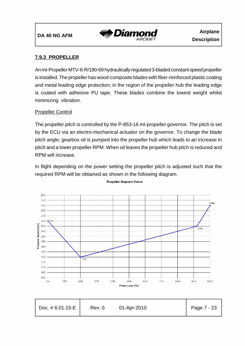
DA 40 NG AFMAirplane
Description
Doc. # 6.01.15-E Rev. 0 01-Apr-2010 Page 7 - 23
7.9.3 PROPELLER
An mt-Propeller MTV-6-R/190-69 hydraulically regulated 3-bladed constant speed propelleris installed. The propeller has wood-composite blades with fiber-reinforced plastic coatingand metal leading edge protection; in the region of the propeller hub the leading edgeis coated with adhesive PU tape. These blades combine the lowest weight whilstminimizing vibration.
Propeller Control
The propeller pitch is controlled by the P-853-16 mt-propeller governor. The pitch is setby the ECU via an electro-mechanical actuator on the governor. To change the bladepitch angle, gearbox oil is pumped into the propeller hub which leads to an increase inpitch and a lower propeller RPM. When oil leaves the propeller hub pitch is reduced andRPM will increase.
In flight depending on the power setting the propeller pitch is adjusted such that therequired RPM will be obtained as shown in the following diagram.
AirplaneDescription
DA 40 NG AFM
Page 7 - 24 Rev. 0 01-Apr-2010 Doc. # 6.01.15-E
Ground Operation:
CAUTIONOperation on the ground at high RPM should be avoided asfar as possible, as the blades could suffer stone damage. Forthis reason a suitable site for engine runs should be selected,where there are no loose stones or similar items.
WARNINGNever rotate the propeller by hand.
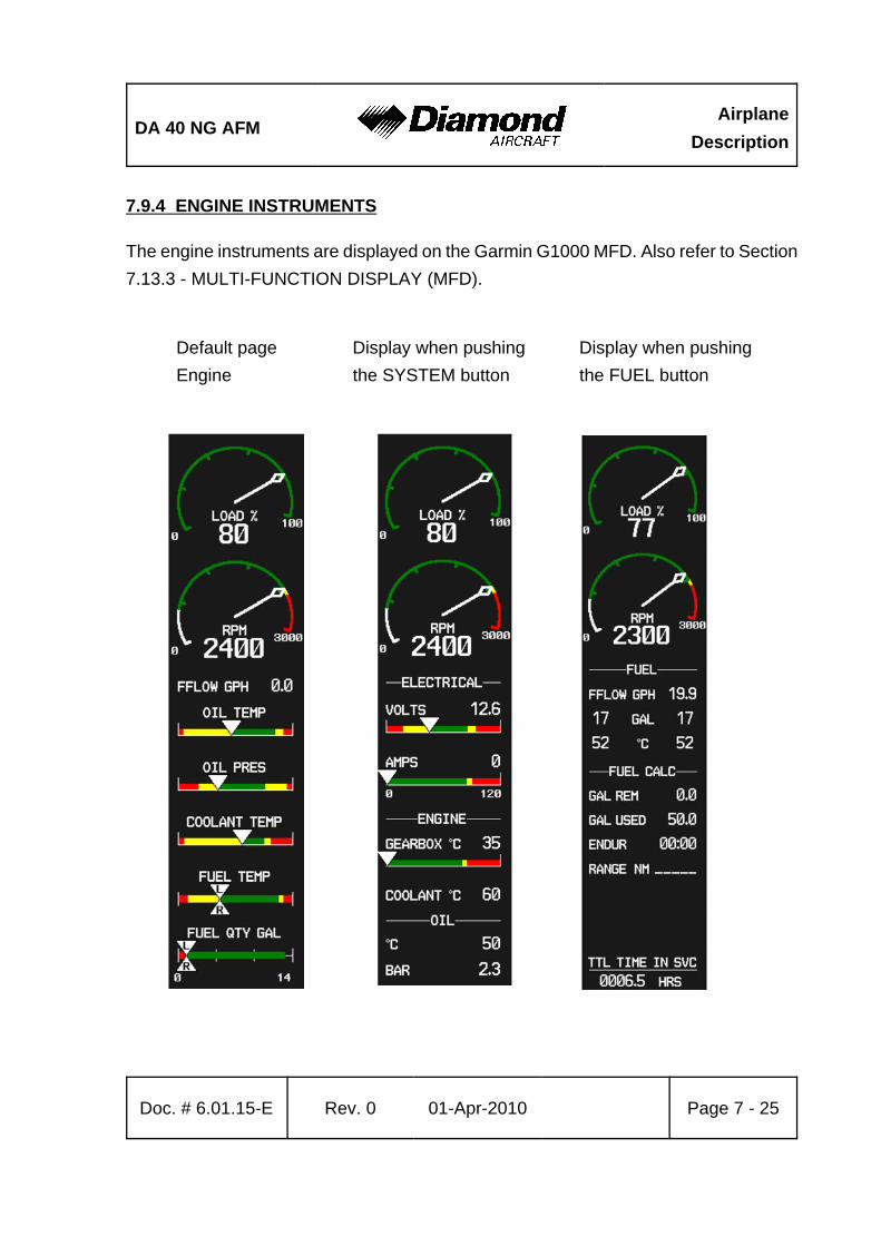
DA 40 NG AFMAirplane
Description
Doc. # 6.01.15-E Rev. 0 01-Apr-2010 Page 7 - 25
7.9.4 ENGINE INSTRUMENTS
The engine instruments are displayed on the Garmin G1000 MFD. Also refer to Section7.13.3 - MULTI-FUNCTION DISPLAY (MFD).
Default page Display when pushing Display when pushingEngine the SYSTEM button the FUEL button

AirplaneDescription
DA 40 NG AFM
Page 7 - 26 Rev. 0 01-Apr-2010 Doc. # 6.01.15-E
NOTEThe figure on previous page is a general demonstration ofa typical G1000 MFD to show the different display modes.The pictured engine instrument markings may not stringentlyagree with the current engine limitations of the DA 40 NG.
NOTEThe fuel calculations on the FUEL CALC portion do not usethe airplane's fuel quantity indicators. The values shown arenumbers which are calculated from the last fuel quantityupdate done by the pilot and actual fuel flow data. Therefore,the endurance and range data is for information only, andmust not be used for flight planning.
Designation Indication Unit
LOAD Available power %
RPM Propeller RPM 1/min
VOLT Volts V
AMPS Ampère A
COOLANT TEMP Coolant temperature °C
GEARBOX Gearbox temperature °C
OIL TEMP Engine oil temperature °C
OIL PRES Oil pressure bar
FUEL QTY Fuel quantity US gal
FFLOW Fuel flow US gal/hr
FUEL TEMP. Fuel temperature °C
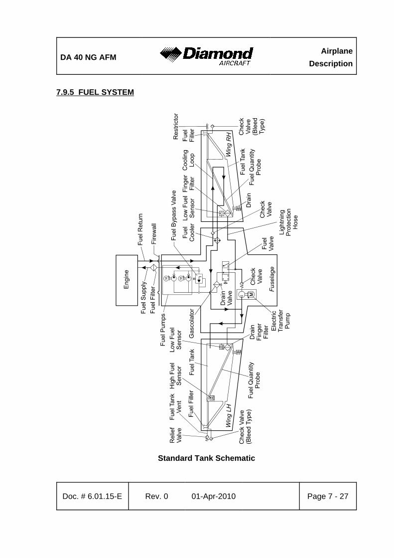
DA 40 NG AFMAirplane
Description
Doc. # 6.01.15-E Rev. 0 01-Apr-2010 Page 7 - 27
7.9.5 FUEL SYSTEM
Standard Tank Schematic

AirplaneDescription
DA 40 NG AFM
Page 7 - 28 Rev. 0 01-Apr-2010 Doc. # 6.01.15-E
Long Range Tank Schematic
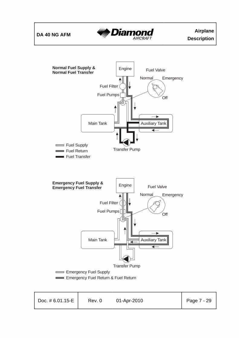
DA 40 NG AFMAirplane
Description
Doc. # 6.01.15-E Rev. 0 01-Apr-2010 Page 7 - 29
Fuel SupplyFuel ReturnFuel Transfer
Engine
Fuel Filter
Fuel Pumps
Normal
Off
Main Tank Auxiliary Tank
Transfer Pump
Fuel ValveNormal Fuel Supply &Normal Fuel Transfer
Emergency
Emergency Fuel SupplyEmergency Fuel Return & Fuel Return
Engine
Fuel Filter
Fuel Pumps
Normal
Off
Main Tank Auxiliary Tank
Transfer Pump
Fuel ValveEmergency Fuel Supply &Emergency Fuel Transfer
Emergency
AirplaneDescription
DA 40 NG AFM
Page 7 - 30 Rev. 0 01-Apr-2010 Doc. # 6.01.15-E
Fuel is stored in the fuel tanks which are located in the wings. Normally fuel is taken fromthe MAIN tank (left wing).
The fuel is injected with high pressure directly into the combustion chambers. The injectionnozzles (one per cylinder) are supplied with fuel by the common rail. Pressure inside therail is generated by a high pressure pump which receives fuel from two independent lowpressure fuel pumps. Both pumps are powered electrically. Depending on the power settingthe rail pressure is controlled by the ECU through an electric valve.
Fuel that is not injected into the combustion chambers is routed through the AUX fueltank (right wing) and fed back into the MAIN fuel tank (left wing). This way hot fuel fromthe rail is cooled and cold fuel in both tanks is heated.
With the help of an electrical transfer pump fuel can be transferred from the AUX tank(right wing) to the MAIN tank (left wing) manually.
The transfer pump is switched off automatically when the auxiliary tank is empty or themain tank is full.
If fuel transfer with the transfer pump becomes impossible for any reason, fuel can alsobe taken directly from the AUX tank (right wing) by switching the fuel valve to theEMERGENCY position. As the return line goes back into the MAIN tank (left wing), fuelwill then be transferred from right to left fuel tank.
As an option additional long range tanks may be installed.
DA 40 NG AFMAirplane
Description
Doc. # 6.01.15-E Rev. 0 01-Apr-2010 Page 7 - 31
CAUTIONSwitching the fuel valve to the EMERGENCY position will startthe transferring of fuel with the help of the electrically drivenand engine driven fuel pumps from the auxiliary tank throughthe fuel return line to the main tank at a rate of approximately45 US gal/h (170 liter/h) with FUEL PUMPS switch in OFFposition. The fuel valve must be switched back to theNORMAL position before the auxiliary tank indication readszero. If the fuel valve is not switched back to the NORMALposition, the engine will stop running as soon as the auxiliarytank is empty.
Fuel Pumps
The engine is supplied with fuel by two parallel installed independent low pressureelectrically driven fuel pumps. During normal operation one of the two fuel pumps is alwaysworking. In case of a low fuel pressure, the ECU switches automatically to the secondfuel pump. During landing and take-off, or in case of a low fuel pressure both fuel pumpscan be activated with the FUEL PUMPS switch. If both fuel pumps are are set to ON thefuel pressure increases.
Each fuel pump is electrically connected to an ECU BUS and protected by a 7.5 A circuitbreaker.
NOTEBy switching between ECU A and B the two independentelectrical fuel pumps are switched over as well. In case of anemergency both pumps can be activated simultaneously bypushing the FUEL PUMPS switch to the ON position.
AirplaneDescription
DA 40 NG AFM
Page 7 - 32 Rev. 0 01-Apr-2010 Doc. # 6.01.15-E
Fuel Valve
The fuel valve is located at the center console. The selectable positions are NORMAL,EMERGENCY and OFF. The desired position is reached by turning the valve handle whilepulling up the safety latch on the valve handle. This is to ensure that a selection is notmade unintentionally.
Standard Fuel Tanks
Main Tank (Left Wing):
The main tank consists of an aluminum chamber and a filler tube which are connectedby a flexible hose. There are two tank vents. One includes a check valve with a capillaryand one includes a pressure relief valve, which operates at 150 mbar (2 PSI) and allowsfuel and air to flow to the outside at higher internal pressure. The relief pressure valveprotects the tank against high pressure if the tank will be overfilled in case of a fuel transferfailure. The check valve with capillary allows air to enter the tank but prevents flow offuel to the outside. The capillary equalizes the air pressure during climb. The hoseterminations are situated on the underside of the wing, approximately 2 meter (7 ft) fromthe wing tip.
Auxiliary Tank (Right Wing):
The auxiliary tank consists of an aluminum chamber and a filler tube which are connectedby a flexible hose. There are two tank vents. One includes a check valve with a capillaryand one includes a capillary. The check valve with capillary allows air to enter the tankduring descent but prevents flow of fuel to the outside. The capillary equalizes the airpressure during climb. The second capillary is installed for additional safety. The hoseterminations are situated on the underside of the wing, approximately 2 meter (7 ft) fromthe wing tip.
In each tank a coarse filter (finger filter) is fitted before the outlet. To allow draining ofthe tank, an outlet valve (drain valve) is installed at the lowest point of the fuel tank.
DA 40 NG AFMAirplane
Description
Doc. # 6.01.15-E Rev. 0 01-Apr-2010 Page 7 - 33
A gascolator is located at the bottom side of the fuselage which is the lowest point of theentire fuel system. A drain valve (pull to drain) is mounted to the gascolator, to allow theremove of water and sediment which has collected in the fuel system.
A capacity probe measures the fuel quantity in each tank. The indication is non-linear,therefore proportional calculations to determine the remaining fuel quantity or directcalculations of fuel consumption are not possible. Information about the fuel consumptioncan be found in Chapter 5 - PERFORMANCE.
Long Range Tank (if installed)
The tank chamber has a capacity of approx. 5 US gal (19 liter). The ventilation systemof the main and the auxiliary tank remains unchanged.
When the fuel quantity indicator reads zero, only the unusable fuel remains in the tank.The useable capacity of each tank is 19.5 US gal, the maximum quantity that can beindicated is 14 US gal. Up to an actual quantity of 14 US gal the indication is correct. Atan actual quantity above 14 US gal the indication remains at 14 US gal.
NOTEWhen the fuel quantity indicator reads 14 US gal, the correctfuel quantity must be determined with the alternate mean forfuel quantity indication. If this measurement is not carried out,the fuel quantity available for flight planning is 14 US gal.

AirplaneDescription
DA 40 NG AFM
Page 7 - 34 Rev. 0 01-Apr-2010 Doc. # 6.01.15-E
Alternate Means For Fuel Quantity Indication
The alternate means for fuel quantityindication allows the fuel quantity in the tankto be determined during the pre-flightinspection. It functions according to theprinciple of communicating containers. Thefuel quantity measuring device has a recesswhich fits the airfoil of the wing. With thisrecess the device is held against the stallstrip at the leading edge of the wing. Theexact position is marked by a bore in the stallstrip. Then the metal connector is pressedagainst the drain of the tank. The amount offuel in the tank can now be read off from thevertical ascending pipe.
For an exact indication the airplane muststand on a horizontal ground.
The designated place for the fuel quantitymeasuring device is the bag on the rear sideof the pilot seat.

DA 40 NG AFMAirplane
Description
Doc. # 6.01.15-E Rev. 0 01-Apr-2010 Page 7 - 35
Pressure Relief Valve
CoolantExpansion
Tank
Thermostatic Valve
Core Engine
WaterPumpCoolant
HeatExchanger
CabinHeat
Exchanger
Bypass Circuit
Radiator Circuit
Radiator Vent Line
7.9.6 COOLING SYSTEM
The engine is liquid cooled. The liquid cooling system consists of a radiator circuit (coolantheat exchanger) and a bypass circuit (cabin heat exchanger). The radiator circuit is onlyopen during hot coolant temperatures. This assures that a cold engine will warm up quickly.Upon reaching approximately 80°C (126°F) coolant temperature the radiator circuit isactivated by a thermostatic valve.
Integrated in the bypass circuit is a coolant to air heat exchanger (cabin heat exchanger)which provides warm air for the cabin heat system.
An coolant expansion tank allows coolant expansion and pressure adjustment. The coolantsystem is protected against overpressure by means of a pressure relief valve.
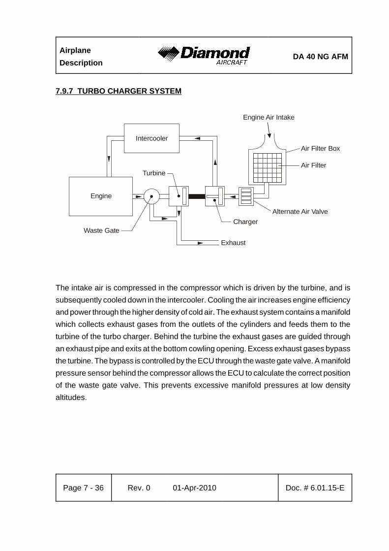
AirplaneDescription
DA 40 NG AFM
Page 7 - 36 Rev. 0 01-Apr-2010 Doc. # 6.01.15-E
Intercooler
Engine
Waste Gate
Turbine
Charger
Exhaust
Alternate Air Valve
Air Filter
Air Filter Box
Engine Air Intake
7.9.7 TURBO CHARGER SYSTEM
The intake air is compressed in the compressor which is driven by the turbine, and issubsequently cooled down in the intercooler. Cooling the air increases engine efficiencyand power through the higher density of cold air. The exhaust system contains a manifoldwhich collects exhaust gases from the outlets of the cylinders and feeds them to theturbine of the turbo charger. Behind the turbine the exhaust gases are guided throughan exhaust pipe and exits at the bottom cowling opening. Excess exhaust gases bypassthe turbine. The bypass is controlled by the ECU through the waste gate valve. A manifoldpressure sensor behind the compressor allows the ECU to calculate the correct positionof the waste gate valve. This prevents excessive manifold pressures at low densityaltitudes.
DA 40 NG AFMAirplane
Description
Doc. # 6.01.15-E Rev. 0 01-Apr-2010 Page 7 - 37
7.9.8 OIL SYSTEMS
The engine has two separate oil systems.
Lubrication System (Engine and Turbo Charger)
The engine lubrication is a wet sump lubrication system. Oil is cooled by a separate cooleron the underside of the engine.
A dip-stick is provided to check the oil quantity through an inspection door on the LH sideof the upper cowling. If required, oil can also be filled in there (for specified oil types referto 2.4 - POWER-PLANT LIMITATIONS).
Gearbox and Propeller Governor System
The second oil circuit lubricates the gear and serves the governor system and theregulation of the propeller.
Gear oil quantity can be checked via an inspection glass which can be reached throughan inspection door on the LH side of the upper cowling.
CAUTIONIf the gear oil quantity is too low, an unscheduledmaintenance is necessary (for specified oil types refer to2.4 - POWER-PLANT LIMITATIONS).
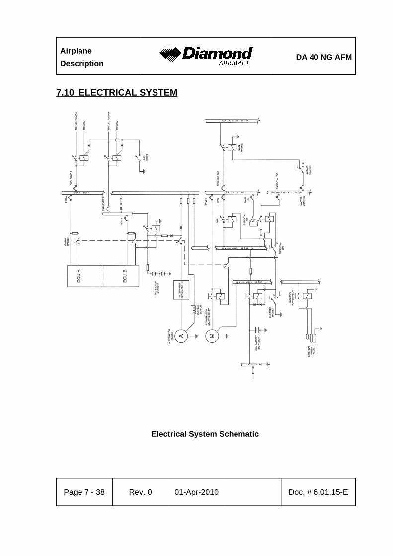
AirplaneDescription
DA 40 NG AFM
Page 7 - 38 Rev. 0 01-Apr-2010 Doc. # 6.01.15-E
7.10 ELECTRICAL SYSTEM
Electrical System Schematic
DA 40 NG AFMAirplane
Description
Doc. # 6.01.15-E Rev. 0 01-Apr-2010 Page 7 - 39
7.10.1 GENERAL
The DA 40 NG has a 28 Volt DC system, which can be sub-divided into:
- Power generation
- Storage
- Distribution
- Consumers
Power Generation
Power generation is provided by a 70 Ampère alternator (generator) which is mountedon the bottom left side of the engine. The alternator is driven by a flat-belt.
The power output line of the alternator is connected to the ENG ECU bus via a 100 Afuse, which is installed in the instrument panel. The power output line also runs throughthe current sensor, which provides an indication of the power being supplied to theelectrical system by the alternator including the current for battery charging.
In the event of a main battery failure the field of the alternator is energized by two 12 V,7.2 Ah sealed-lead-acid batteries (ECU backup batteries) which are installed behind thefirst ring frame. The ENGINE MASTER switch connects the ECU backup battery to thealternator voltage regulator via a 10 A fuse.
Alternator Control:
The alternator control unit includes a comprehensive set of diagnostic functions that willwarn the operator using a warning message (ALTN FAIL) on the G1000 system in caseof over- or undervoltage as well as a couple of other internal warning levels.

AirplaneDescription
DA 40 NG AFM
Page 7 - 40 Rev. 0 01-Apr-2010 Doc. # 6.01.15-E
Storage
Main battery power is stored in a 24 V, 13.6 Ah lead-acid battery mounted behind thebaggage compartment frame. The main battery is connected to the battery bus via thebattery-relay which is installed in the relay junction box behind the baggage compartmentframe.
The battery relay is controlled with the ELECTRIC MASTER key switch which is locatedin the center of the instrument panel.
In addition, two 12 V, 7.2 Ah sealed-lead-acid batteries (ECU backup-batteries) areinstalled behind the first ring frame as a further source of electrical power for the EngineControl Unit (ECU B only).
Under normal operating conditions the ECU backup batteries are charged by the ECUbus. In the event of an alternator failure and a depleted main battery the ECU backupbatteries automatically supply electrical power to ECU B via a 32 A fuse. This preventsthe engine from stopping in the unlikely event of an alternator failure and a totallydischarged main battery.
In addition, a non-rechargeable dry battery is installed in the IFR model as a further sourceof power for the attitude gyro (artificial horizon) and the flood light. When theEMERGENCY switch is set to ON, these two systems are supplied with power for 1 hour,independent of all other electrical consumers. During each 100 hour inspection, thisbattery is checked for proper functioning. Every 2 years or after use (broken seal on theswitch) the battery pack must be replaced.
DA 40 NG AFMAirplane
Description
Doc. # 6.01.15-E Rev. 0 01-Apr-2010 Page 7 - 41
Distribution
Electrical power is distributed via the hot battery bus, the battery bus 1, the battery bus 2,the ECU-bus, the main bus, the essential bus and the avionic bus.
Hot Battery Bus:
The hot battery bus is directly connected to the main-battery installed in the relay junctionbox and cannot be disconnected from the main battery. The hot battery bus providespower to the accessory power plug and ELT which are protected by their own fuses.
Battery Bus 1:
The battery bus 1 is connected to the main-battery via the battery-relay which can becontrolled by the ELECTRIC MASTER key switch. The battery bus 1 provides power tothe battery bus 2 and heavy duty power to the starter.
The battery bus 1 is also connected to the power input line of the external power plug.
Battery Bus 2:
The battery bus 2 is connected to the battery bus 1 via a 100 A fuse and provides powerto the ECU bus via a 80 A fuse. It also provides power to the main bus via the powerrelay which can be controlled by the ELECTRIC MASTER key switch and the ESSENTIALBUS switch. The ELECTRIC MASTER key switch must be set to ON and the ESSENTIALBUS switch must be set to OFF to connect the battery bus to the main bus.
ECU Bus:
The ECU bus is connected to the battery bus 2 via a 80 A fuse and provides power forthe ECU A and ECU B and their fuel pumps. It is also connected to the power outputline of the alternator via a 100 A fuse. It also provides power for charging the ECU backup-battery. The ENGINE MASTER switch must be set to ON to activate the ECU A andECU B to the ECU bus.
AirplaneDescription
DA 40 NG AFM
Page 7 - 42 Rev. 0 01-Apr-2010 Doc. # 6.01.15-E
Main Bus:
The main bus is connected to the battery bus via the power-relay. It provides power tothe consumers directly connected to the main bus and the avionic bus via the avionicmaster-relay. The AVIONIC MASTER switch must be set to ON to connect the main busto the avionic bus. Under normal operating conditions the main bus is also connectedto the essential bus via the essential tie-relay. In the event of an alternator failure thepilot must switch ON the ESSENTIAL BUS switch (refer to Section 3.6 - FAILURES INTHE ELECTRICAL SYSTEM). This separates the main bus from the battery bus andthe essential bus and the equipment connected to the main bus no longer has power.
Essential Bus:
Under normal operating conditions the essential bus is connected to the main bus viathe essential tie-relay. The essential bus provides power to the consumers connectedto the essential bus. The AVIONIC MASTER switch must be set to ON to connect theessential bus to the avionic bus. In the event of an alternator failure the pilot must switchON the ESSENTIAL BUS switch (refer to Section 3.6 - FAILURES OF THE ELECTRICALSYSTEM). This separates the essential bus from the main bus. The essential bus is thenconnected to the battery bus 2 which provides battery power for a limited time to theequipment essential for safe flight and landing.
Consumers
The individual consumers (e.g. radio, electrical fuel transfer pump, position lights, etc.)are connected to the appropriate bus via automatic circuit breakers.
Designations and abbreviations used to identify the circuit breakers are explained inSection 1.5 - DEFINITIONS AND ABBREVIATIONS.
DA 40 NG AFMAirplane
Description
Doc. # 6.01.15-E Rev. 0 01-Apr-2010 Page 7 - 43
Voltmeter
The voltmeter shows the voltage of the essential bus. Under normal operating conditionsthe alternator voltage is shown, otherwise it is the voltage of the main battery.
Ammeter
The ammeter displays the intensity of current which is supplied to the electrical systemby the alternator, including the current for battery charging.
Landing and Taxi Lights
Landing and taxi lights are built into the left wing, and are each operated by means ofa switch (LANDING, TAXI) on the row of switches on the instrument panel.
Position and Strobe Lights
Combined position and strobe lights (anti collision lights) are installed on both wing tips.Each system is operated by a switch (POSITION, STROBE) on the row of switches onthe instrument panel.
Flood Light
A two-dimensional light emitter is mounted above the instrument panel. It illuminates theinstrument panel as well as all levers, switches, etc. With a rotary button (FLOOD) inthe left-hand section of the instrument panel the flood light is switched on and itsbrightness is adjusted.

AirplaneDescription
DA 40 NG AFM
Page 7 - 44 Rev. 0 01-Apr-2010 Doc. # 6.01.15-E
Right Wing TipLight Assy
Reading Lights (3 off)
Instrument PanelFlood Light Strip
Left Wing TipLight Assy
Landing/TaxiLight Assy
Instrument Lighting
With a rotary button (INSTRUMENT) in the left-hand section of the instrument panel theinternal lighting of the instruments is switched on and its brightness is adjusted.
DA 40 NG AFMAirplane
Description
Doc. # 6.01.15-E Rev. 0 01-Apr-2010 Page 7 - 45
Pitot Heating
The Pitot probe, which provides measurement for the Pitot-static system, is electricallyheated. The heating is activated with a switch (PITOT) on the row of switches on theinstrument panel. The temperature is automatically kept constant by means of a thermalswitch on the Pitot probe, and as an additional safety measure a thermal fuse is builtin. If this thermal fuse is activated, the Pitot heating can no longer be switched on. PITOTFAIL will be displayed, if the thermal fuse or the thermal switch is activated and thePITOT HT is set to ON. The PITOT HT OFF is on if the Pitot heating is switched off.
AirplaneDescription
DA 40 NG AFM
Page 7 - 46 Rev. 0 01-Apr-2010 Doc. # 6.01.15-E
7.10.2 ENGINE CONTROL UNIT / ECU
Engine Control and Regulation
The Electrical ECU is used to control the engine actuator (e.g. fuel injector) accordingto the engine sensor information. The ECU monitors, controls and regulates all importantparameters for engine operation.
Sensors installed are:
- Oil temperature (lubrication system engine) / OIL TEMP- Oil pressure (lubrication system engine) / OIL PRES
- Coolant temperature / COOLANT TEMP- Gearbox temperature / GEARBOX- Camshaft RPM (twice)- Crankshaft RPM (twice)- Fuel pressure in the common rail- Manifold pressure- Manifold air temperature- Ambient air pressure- Propeller governor / oil pressure- Power lever position (twice)- Voltage- Starter switch signal- Fuel pressure- VOTER switch signal- ECU TEST switch signal

DA 40 NG AFMAirplane
Description
Doc. # 6.01.15-E Rev. 0 01-Apr-2010 Page 7 - 47
In accordance with the received signals and a comparison with the programmedcharacteristic diagrams the necessary inputs are calculated and transmitted by thefollowing signal lines to the engine:
- Signal for propeller governor pressure valve- Signal for the rail-pressure regulation valve- Signal for each of the 4 injection nozzles - Activation of the glow plugs- Signal for the waste gate valve
The following alerts are displayed on the PFD of the G1000:
- Glow sparks active- Status ECU A- Status ECU B- Low fuel pressure warning
The Electrical ECU consists of two similar ECUs. A VOTER switch is integrated in theElectrical ECU and proposes an ECU to control the engine regarding the ECU operatinghours or in case of a failure the ECU with better engine control capability.
A fault in one of the ECUs is indicated by a caution message on the PFD (ECU A/B FAIL).After the indication of the ECU A/B FAIL caution message, the engine must be serviced.
AirplaneDescription
DA 40 NG AFM
Page 7 - 48 Rev. 0 01-Apr-2010 Doc. # 6.01.15-E
7.10.3 WARNING, CAUTION AND ADVISORY MESSAGES
Crew Alerting System (CAS)
The G1000 crew alerting system (CAS) is designed to provide visual and aural alertsto the flight crew. Alerts are divided into three levels as follows:
WARNING
CAUTION
ADVISORY
Crew alerts will appear in the alerts window on the PFD. In this window warnings willappear at the top, followed by cautions and advisories, respectively. Within the criticalitylevels, messages will appear from newest (top) to oldest (bottom).
At the low right corner of the display there is a MSG (message) soft key. The MSG keyprovides two functions in the CAS:
1. Pressing the MSG key acknowledges a new master warning / caution / advisoryindication.
2. An additional MSG key press with no master alert indication active will open a pop-upauxiliary flight display (AFD) page that contains information for all active alerts.
This structure allows the crew to scroll through all system alerts if the alerts windowoverflows. This approach displays the most critical alerts close to the pilot´s primary fieldof view at all times, with the option of allowing lower criticality alerts to overflow and beaccessible from the pop-up AFD page/window.
DA 40 NG AFMAirplane
Description
Doc. # 6.01.15-E Rev. 0 01-Apr-2010 Page 7 - 49
Alert Levels
Level Text Color Importance Audible Tone
Warning Red May requireimmediate
corrective action
Warning chimetone which repeatswithout delay untilacknowledged by
the crew
Caution Yellow May require futurecorrective action
Single warningchime tone
AnnunciationAdvisory White None
Message Advisory White None
Safe OperationAnnunciation Green Lowest None
Warning, Caution and Advisory Alerts
A list of all alerts is given in Section 2.6 - WARNING, CAUTION AND STATUS LIGHTS.
AirplaneDescription
DA 40 NG AFM
Page 7 - 50 Rev. 0 01-Apr-2010 Doc. # 6.01.15-E
7.11 PITOT-STATIC SYSTEM
Total pressure is measured at the leading edge of a Pitot probe under the left wing. Staticpressure is measured through the static ports in the rear fuselage. To protect againstdirt and condensation there are filters in the system. The Pitot probe is electrically heated.
With the alternate static valve, the static pressure in the cabin can be used as staticpressure source in the event of a failure of the static system.
7.12 STALL WARNING SYSTEM
If airspeed drops, suction on the orifice at the leading edge of the left wing will increaseuntil the stall warning horn, located in the instrument panel, will sound. The horn becomesprogressively louder the closer one gets to stalling speed. Suction at an orifice on theleft wing leading edge activates the horn via a hose. The orifice for the stall warning inthe left wing is marked by a red ring.
DA 40 NG AFMAirplane
Description
Doc. # 6.01.15-E Rev. 0 01-Apr-2010 Page 7 - 51
7.13 GARMIN G1000 INTEGRATED AVIONICS SYSTEM
7.13.1 GENERAL
A remote avionic box is located behind the aft baggage compartment frame. A push-to-talk(PTT) button for the COM portion of the G1000 is mounted on the end of each controlstick. There are connection facilities for up to 4 headsets between the front seats.
Refer to the Garmin G1000 Cockpit Reference Guide, Garmin P/N 190-00953-00 andPilot's Guide, P/N 190-00952-00 for complete descriptions of the G1000 system andoperating procedures.
7.13.2 PRIMARY FLIGHT DISPLAY (PFD)
The primary flight display (PFD; see figure below) typically displays airspeed, attitude,altitude, and heading information in a traditional format. Slip information is shown as atrapezoid under the bank pointer. One width of the trapezoid is equal to a one ball widthslip. Rate of turn information is shown on the scale above the compass rose; full scaledeflection is equal to a standard rate turn. The following controls are available on thePFD (clockwise from top right):
* Communications frequency volume and squelch knob
* Communications frequency set knobs
* Communications frequency transfer button
* Altimeter setting knob (baro set)
* Course knob
* Map range knob and cursor control
* FMS control buttons and knob
* PFD softkey buttons, including master warning/caution acknowledgment
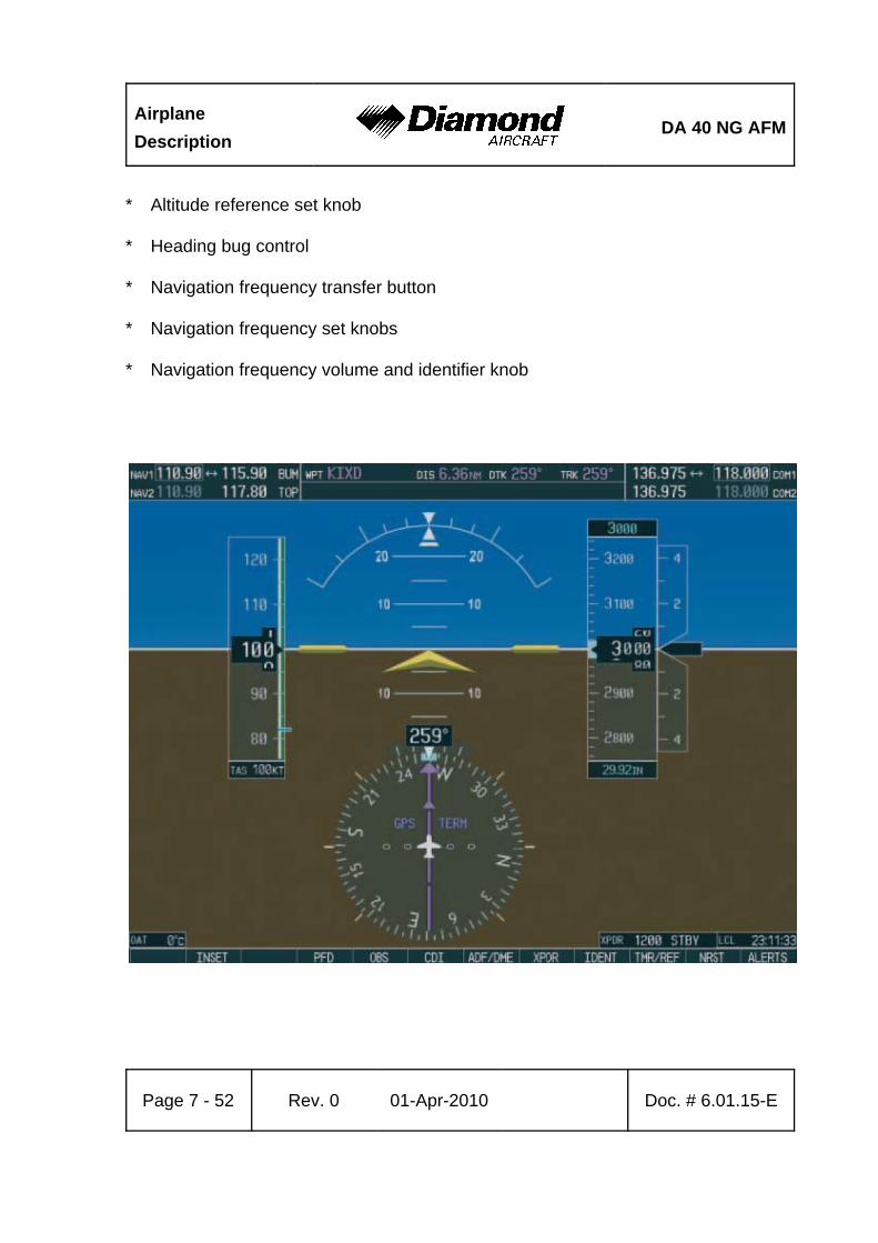
AirplaneDescription
DA 40 NG AFM
Page 7 - 52 Rev. 0 01-Apr-2010 Doc. # 6.01.15-E
* Altitude reference set knob
* Heading bug control
* Navigation frequency transfer button
* Navigation frequency set knobs
* Navigation frequency volume and identifier knob
DA 40 NG AFMAirplane
Description
Doc. # 6.01.15-E Rev. 0 01-Apr-2010 Page 7 - 53
The PFD displays the crew alerting (annunciator) system. When a warning or cautionmessage is received, a warning or caution annunciator will flash on the PFD, accompaniedby an aural tone. A warning is accompanied by a repeating tone, and a caution isaccompanied by a single tone. Acknowledging the alert will cancel the flashing and providea text description of the message. Refer to Chapter 3. - EMERGENCY PROCEDURES,4B. - ABNORMAL OPERATING PROCEDURES and Section 7.10.3 - WARNING,CAUTION AND ADVISORY MESSAGES. Advisory messages related to G1000 system status are shown in white and areaccompanied by a white flashing ADVISORY alert. Refer to the G1000 Pilot's Guide andCockpit Reference Guide for descriptions of the messages and recommended actions.
Trend vectors are shown on the airspeed and altimeter displays as a magenta linepredicting 6 seconds at the current rate. The turn rate indicator also functions as a trendindicator on the compass scale.
The PFD can be displayed in a composite format for emergency use by pressing theDISPLAY BACKUP button on the audio panel. In the composite mode, the full crewalerting function remains, but no map functions are available.
7.13.3 MULTI-FUNCTION DISPLAY (MFD)
The multi-function display (MFD) typically displays engine data, maps, terrain, traffic andtopography displays, and flight planning and progress information. The display unit isidentical to the PFD and contains the same controls as previously listed. Additionally theMFD incorporates the controls for the autopilot system.
Engine instruments are displayed on the MFD. Discrete engine sensor information isprocessed by the Garmin Engine Airframe (GEA) sub-system. When an engine sensorindicates a value outside the normal operating range, the legend will turn yellow for cautionrange, and turn red and flash for warning range.
Also refer to Section 7.9.4 - ENGINE INSTRUMENTS.
AirplaneDescription
DA 40 NG AFM
Page 7 - 54 Rev. 0 01-Apr-2010 Doc. # 6.01.15-E
7.13.4 AUDIO PANEL
The audio panel contains traditional transmitter and receiver selectors, as well as anintegral intercom and marker beacon system. The marker beacon lights appear on thePFD. In addition, a clearance recorder records the last 2 ½ minutes of received audio.Lights above the selections indicate what selections are active. Pressing the red DISPLAYBACKUP button on the audio panel causes both the PFD and MFD to display a compositemode.
7.13.5 ATTITUDE AND HEADING REFERENCE SYSTEM (AHRS)
The attitude and heading reference system (AHRS) uses GPS, rate sensors, air data,and magnetic variation to determine pitch and roll attitude, sideslip and heading. Operationis possible in a degraded mode if the system loses any of these inputs. Status messagesalert the crew of the loss of any of these inputs. The AHRS will align while the airplaneis in motion, but will align quicker if the wings are kept level during the alignment process.
7.13.6 AIR DATA COMPUTER (ADC)
The air data computer (ADC) provides airspeed, altitude, vertical speed, and airtemperature to the display system. In addition to the primary displays, this informationis used by the FMS and TIS systems.
DA 40 NG AFMAirplane
Description
Doc. # 6.01.15-E Rev. 0 01-Apr-2010 Page 7 - 55
7.14 AVIONICS
7.14.1 AUTOPILOT SYSTEM
General
The GFC 700 Automatic Flight Control System (AFCS) is a two axis autopilot and flightdirector system which provides the pilot with the following features: Altitude Preselectand Altitude Hold (ALT); Flight Level Change with Airspeed Hold (FLC); Vertical SpeedHold (VS); Navigation Tracking for VOR (NAV) and GPS (GPS); Heading Hold (HDG);Approach mode and Go Around (GA) pitch/roll guidance. The system consists of autopilotcontrols on the multi-function display (MFD), servos with autopilot processing logic, FlightDirector processing logic in the GIA´s, a control stick-mounted elevator trim switch, acontrol stick mounted trim interrupt and autopilot disconnect switch, a control stickmounted CWS (Control Wheel Steering) switch, a power lever mounted GA (go-around)switch, and PFD/MFD-mounted altitude preselect, heading, and course knobs.
The GFC 700 autopilot contains an electric pitch trim system which is used by the autopilotfor automatic pitch trim during autopilot operation and by the pilot for manual electric pitchtrim when the autopilot is not engaged. The manual electric pitch trim is operated by asplit switch on the pilot´s control stick.
The GFC 700 autopilot and manual electric trim (MET) will not operate until the systemhas satisfactorily completed a preflight test. The preflight test begins automatically withinitial power application to the autopilot (AVIONIC MASTER switch is set to the ONposition).
The following conditions will cause the autopilot to automatically disconnect:
- Electrical power failure- Internal autopilot system failure- AHRS malfunction- Loss of air data computer information
AirplaneDescription
DA 40 NG AFM
Page 7 - 56 Rev. 0 01-Apr-2010 Doc. # 6.01.15-E
The GFC 700 may be manually disconnected by any of the following means:
- Depressing the red AP DISC button on the pilot's or copilot's control stick- Moving the left (outboard) side of the manual electric trim switch on the pilot's control
stick- Pushing the AP button on the autopilot mode controller when the autopilot is
engaged- Depressing the GA button on the left side of the power lever- Pulling the AUTOPILOT circuit breaker- Turning off the AVIONICS MASTER switch- Turning off the ELECTRIC MASTER key switch
In addition, the CWS (control wheel steering) switch on the pilot's control stick willdisconnect the autopilot servos from the airplane flight controls as long as the CWS switchis depressed.
Power to the GFC 700 autopilot and electric trim system is supplied through the AVIONICMASTER switch and the AUTOPILOT circuit breaker. The AVIONIC MASTER switchcan be used as an additional means to disable the autopilot and electric trim system.The red AP DISC switch on the pilot's control stick will interrupt power to the manualelectric trim for as long as the switch is depressed.
Loss of instruments or components of the G1000 system will affect the GFC 700 AFCSas follows:
- Loss of the AHRS will cause the autopilot to disconnect. The autopilot and flightdirector will be inoperative. Manual electric trim will be available.
- Loss of the heading function of the AHRS will result in loss of the HDG mode. Ifin HDG mode at the time heading is lost, the autopilot will revert to basic roll Mode(ROL).
- Loss of the MFD will not cause the autopilot to disconnect, and will remain engagedwith limited functionality, but the autopilot cannot be re-engaged after disconnectby the pilot.
DA 40 NG AFMAirplane
Description
Doc. # 6.01.15-E Rev. 0 01-Apr-2010 Page 7 - 57
- Loss of the PFD will cause the autopilot to disconnect. The autopilot and flightdirector will be inoperative. Manual electric trim will be available.
- Loss of air data computer information will cause the autopilot to disconnect. Theautopilot will be inoperative. The flight director will be available except for air datamodes (ALT, VS, FLC). Manual electric trim is available.
- Loss of GIA #1 will cause the autopilot to disconnect. The autopilot, flight directorand manual electric trim will be inoperative. Loss of GIA #2 will also prevent autopilotand manual electric trim operation, but flight director will be available.
- Loss of the standby airspeed indicator, standby attitude indicator, standby altimeter,or compass will have no effect on the autopilot.
- Loss of both GPS systems will cause the autopilot and flight director to operate inNAV modes (LOC, BC, VOR, VAPP) with reduced accuracy. Course intercept andstation crossing performance may be improved by executing intercepts and stationcrossings in HDG mode, then reselecting NAV mode.
WARNINGFollowing an autopilot or electric trim malfunction do notre-engage the autopilot or manual electric trim or reset theAUTOPILOT circuit breaker until the cause of the malfunctionhas been determined and corrected.
The GFC 700 Automatic Flight Control system (AFCS) installed in the Diamond DA 40 NGconsists of the following components:
- One GDU which contains the following mode control buttons: AP (Autopilot engage/disengage)FD (Flight director On/Off)HDG (Heading mode On/Off)NAV (Nav mode On/Off) APR (Approach mode On/Off)ALT (Altitude hold mode On/Off)VS (Vertical speed mode On/Off)
AirplaneDescription
DA 40 NG AFM
Page 7 - 58 Rev. 0 01-Apr-2010 Doc. # 6.01.15-E
FLC (Flight level change mode On/Off)NOSE UP and NOSE DN (Vertical mode reference change)VNV (Vertical navigation mode On/Off)
This GDU is installed as the MFD.
- Servos with autopilot processing logic in the pitch, roll, and pitch trim control systems- Servo mounts and brackets- Flight director processing logic in the GIAs- Control stick-mounted manual electric trim (MET) switch (split switch) for pitch trim- Control stick-mounted trim interrupt and autopilot disconnect switch- Control stick-mounted CWS (Control Wheel Steering) switch- Remote-mounted go-around switch (on the left side of the power lever knob)- PFD/MFD mounted altitude preselect knob (ALT)- PFD/MFD mounted heading select knob (HDG)
Flight director commands and autopilot modes are displayed on the PFD. Full AFCSfunctionality is only available with both displays operating, and will disconnect undercertain reversionary conditions.
Upon initial system power-up, the system undergoes a preflight test. At the end of thetest, the autopilot disconnect tone sounds and the PFT and AFCS annunciations areremoved. Successful completion of the preflight test is required for the autopilot andmanual electric trim to engage.
Annunciation of the flight director and autopilot modes is shown in the lower status fieldof the PFD. In general, green indicates active modes and white indicates armed modes.When a mode is directly selected by the pilot, no flashing of the mode will occur. Whenautomatic mode changes occur, they will be annunciated with a flashing annunciationof the new mode for ten seconds in green. If a mode becomes unavailable for whatever
DA 40 NG AFMAirplane
Description
Doc. # 6.01.15-E Rev. 0 01-Apr-2010 Page 7 - 59
reason, the mode will flash for ten seconds in yellow and be replaced by the new modein green.
Normal autopilot disconnects are annunciated with a yellow flashing AP on the PFDaccompanied by a two second autopilot disconnect tone. Normal disconnects are thoseinitiated by the pilot with the AP DISC switch, the MET switch, the AP button on the MFDmode controller, or the GA button. Abnormal disconnects will be accompanied by a redflashing AP on the PFD accompanied by a continuous autopilot disconnect tone. Thedisconnect tone and flashing alert may be cancelled by pressing the AP DISC switchor the left side of the MET switch.
Refer to the Garmin G1000 Cockpit Reference Guide, P/N 190-00953-00, Rev. 0 or later,and Garmin G1000 Pilot's Guide for the Diamond DA 40 NG, P/N 190-952-00, Rev. 0or later, for complete descriptions of the G1000 system and operating procedures.
Power Supply
The AVIONIC MASTER switch supplies power to the avionics bus bar of the radio circuitbreakers and the autopilot circuit breaker.
The following circuit breaker is used to protect the following element of the GFC 700autopilot:
Circuit Breaker Function
AUTOPILOT Supplies power to the autopilot pitch, roll, and pitch trimservos.
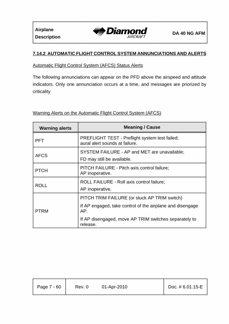
AirplaneDescription
DA 40 NG AFM
Page 7 - 60 Rev. 0 01-Apr-2010 Doc. # 6.01.15-E
7.14.2 AUTOMATIC FLIGHT CONTROL SYSTEM ANNUNCIATIONS AND ALERTS
Automatic Flight Control System (AFCS) Status Alerts
The following annunciations can appear on the PFD above the airspeed and attitudeindicators. Only one annunciation occurs at a time, and messages are priorized bycriticality
Warning Alerts on the Automatic Flight Control System (AFCS)
Warning alerts Meaning / Cause
PFT PREFLIGHT TEST - Preflight system test failed;aural alert sounds at failure.
AFCSSYSTEM FAILURE - AP and MET are unavailable;FD may still be available.
PTCH PITCH FAILURE - Pitch axis control failure;AP inoperative.
ROLLROLL FAILURE - Roll axis control failure;AP inoperative.
PTRM
PITCH TRIM FAILURE (or stuck AP TRIM switch)
If AP engaged, take control of the airplane and disengageAP.
If AP disengaged, move AP TRIM switches separately torelease.
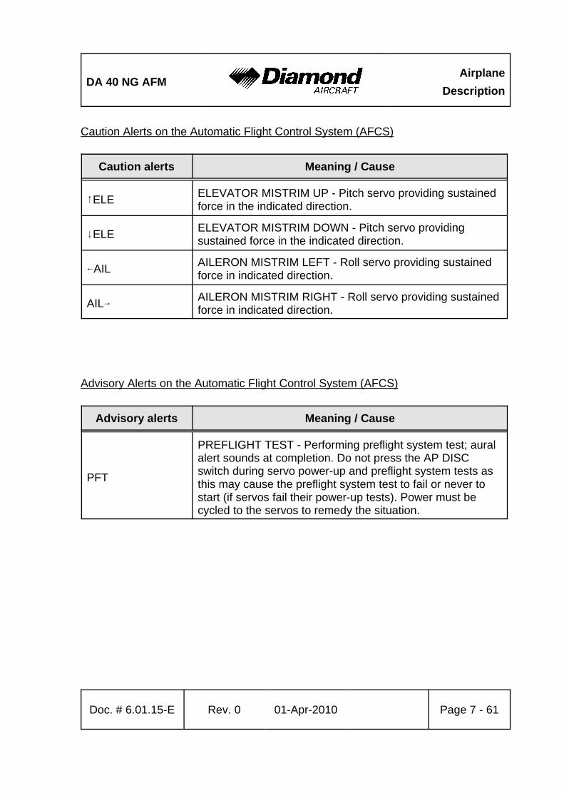
DA 40 NG AFMAirplane
Description
Doc. # 6.01.15-E Rev. 0 01-Apr-2010 Page 7 - 61
Caution Alerts on the Automatic Flight Control System (AFCS)
Caution alerts Meaning / Cause
8ELE ELEVATOR MISTRIM UP - Pitch servo providing sustainedforce in the indicated direction.
9ELE ELEVATOR MISTRIM DOWN - Pitch servo providingsustained force in the indicated direction.
7AIL AILERON MISTRIM LEFT - Roll servo providing sustainedforce in indicated direction.
AIL6 AILERON MISTRIM RIGHT - Roll servo providing sustainedforce in indicated direction.
Advisory Alerts on the Automatic Flight Control System (AFCS)
Advisory alerts Meaning / Cause
PFT
PREFLIGHT TEST - Performing preflight system test; auralalert sounds at completion. Do not press the AP DISCswitch during servo power-up and preflight system tests asthis may cause the preflight system test to fail or never tostart (if servos fail their power-up tests). Power must becycled to the servos to remedy the situation.

AirplaneDescription
DA 40 NG AFM
Page 7 - 62 Rev. 0 01-Apr-2010 Doc. # 6.01.15-E
Intentionally left blank.

DA 40 NG AFM Handling
Doc. # 6.01.15-E Rev. 0 01-Apr-2010 Page 8 - 1
CHAPTER 8AIRPLANE HANDLING, CARE AND MAINTENANCE
Page
8.1 INTRODUCTION . . . . . . . . . . . . . . . . . . . . . . . . . . . . . . . . . . . . . . . 8-28.2 AIRPLANE INSPECTION INTERVALS . . . . . . . . . . . . . . . . . . . . . . 8-28.3 AIRPLANE ALTERATIONS OR REPAIRS . . . . . . . . . . . . . . . . . . . 8-38.4 GROUND HANDLING / ROAD TRANSPORT . . . . . . . . . . . . . . . . . 8-3
8.4.1 GROUND HANDLING WITHOUT TOW BAR . . . . . . . . . . . . 8-38.4.2 GROUND HANDLING WITH TOW BAR . . . . . . . . . . . . . . . . 8-48.4.3 PARKING . . . . . . . . . . . . . . . . . . . . . . . . . . . . . . . . . . . . . . . 8-68.4.4 MOORING . . . . . . . . . . . . . . . . . . . . . . . . . . . . . . . . . . . . . . . 8-88.4.5 JACKING . . . . . . . . . . . . . . . . . . . . . . . . . . . . . . . . . . . . . . . . 8-88.4.6 ALIGNMENT . . . . . . . . . . . . . . . . . . . . . . . . . . . . . . . . . . . . . 8-88.4.7 ROAD TRANSPORT . . . . . . . . . . . . . . . . . . . . . . . . . . . . . . . 8-9
8.5 CLEANING AND CARE . . . . . . . . . . . . . . . . . . . . . . . . . . . . . . . . 8-108.5.1 PAINTED SURFACES . . . . . . . . . . . . . . . . . . . . . . . . . . . . 8-108.5.2 CANOPY AND REAR DOOR . . . . . . . . . . . . . . . . . . . . . . . 8-108.5.3 PROPELLER . . . . . . . . . . . . . . . . . . . . . . . . . . . . . . . . . . . . 8-118.5.4 ENGINE . . . . . . . . . . . . . . . . . . . . . . . . . . . . . . . . . . . . . . . 8-118.5.5 INTERIOR SURFACES . . . . . . . . . . . . . . . . . . . . . . . . . . . . 8-11
8.6 GROUND DE-ICING . . . . . . . . . . . . . . . . . . . . . . . . . . . . . . . . . . . 8-12
Handling DA 40 NG AFM
Page 8 - 2 Rev. 0 01-Apr-2010 Doc. # 6.01.15-E
8.1 INTRODUCTION
Chapter 8 contains the manufacturer's recommended procedures for proper groundhandling and servicing of the airplane. The Airplane Maintenance Manual(Doc. No. 6.02.15) lists certain inspection and maintenance requirements which mustbe followed if the airplane is to retain a new plane performance and reliability.
8.2 AIRPLANE INSPECTION INTERVALS
Inspections are scheduled every 100, 200 and 1000 hours. Independent of the flight hoursan annual inspection must be performed every year. The respective inspection checklistsare prescribed in the Airplane Maintenance Manual, Chapter 05.
For maintenance work on engine and propeller, the currently effective Operator's Manuals,Service Instructions, Service Letters and Service Bulletins of Austro Engine andmt-propeller must be followed. For airframe inspections, the currently effectivechecklists/manuals, Service Bulletins and Service Instructions of the manufacturer mustbe followed.
CAUTIONUnscheduled maintenance checks are required after:
- Hard landings- Propeller strike- Engine fire- Lightning strike- Occurrence of other malfunctions and damage
Unscheduled maintenance checks are described in theAirplane Maintenance Manual (Doc. No. 6.02.15;Section 05-50).
DA 40 NG AFM Handling
Doc. # 6.01.15-E Rev. 0 01-Apr-2010 Page 8 - 3
8.3 AIRPLANE ALTERATIONS OR REPAIRS
Alterations or repairs of the airplane may be carried out only according to the AirplaneMaintenance Manual, Doc. No. 6.02.15, and only by authorized personnel.
8.4 GROUND HANDLING / ROAD TRANSPORT
8.4.1 GROUND HANDLING WITHOUT TOW BAR
During forward traversing the nose wheel will follow the movement of the airplane. Changein direction is achieved by pulling on the propeller near the spinner. To traverse in therear direction, the tail section of the airplane should be pushed down until the nose wheelis clear of the ground. This method can also be used to turn the airplane around its mainlanding gear.
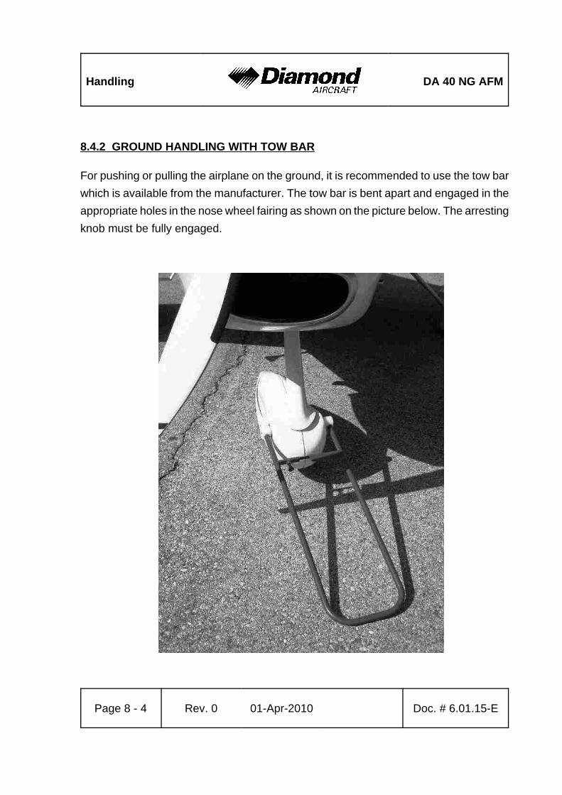
Handling DA 40 NG AFM
Page 8 - 4 Rev. 0 01-Apr-2010 Doc. # 6.01.15-E
8.4.2 GROUND HANDLING WITH TOW BAR
For pushing or pulling the airplane on the ground, it is recommended to use the tow barwhich is available from the manufacturer. The tow bar is bent apart and engaged in theappropriate holes in the nose wheel fairing as shown on the picture below. The arrestingknob must be fully engaged.
DA 40 NG AFM Handling
Doc. # 6.01.15-E Rev. 0 01-Apr-2010 Page 8 - 5
WARNINGThe tow bar must be removed before starting the engine.
CAUTIONThe tow bar may only be used for moving the airplane on theground by hand. After moving the airplane, the tow bar mustbe removed.
NOTEWhen moving the airplane rearward, the tow bar must be heldfirmly to prevent abrupt sideward deflection of the nose wheel.
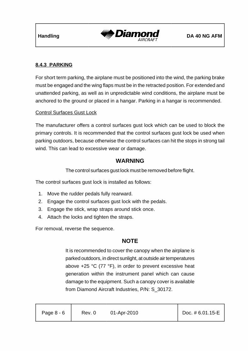
Handling DA 40 NG AFM
Page 8 - 6 Rev. 0 01-Apr-2010 Doc. # 6.01.15-E
8.4.3 PARKING
For short term parking, the airplane must be positioned into the wind, the parking brakemust be engaged and the wing flaps must be in the retracted position. For extended andunattended parking, as well as in unpredictable wind conditions, the airplane must beanchored to the ground or placed in a hangar. Parking in a hangar is recommended.
Control Surfaces Gust Lock
The manufacturer offers a control surfaces gust lock which can be used to block theprimary controls. It is recommended that the control surfaces gust lock be used whenparking outdoors, because otherwise the control surfaces can hit the stops in strong tailwind. This can lead to excessive wear or damage.
WARNINGThe control surfaces gust lock must be removed before flight.
The control surfaces gust lock is installed as follows:
1. Move the rudder pedals fully rearward.2. Engage the control surfaces gust lock with the pedals.3. Engage the stick, wrap straps around stick once.4. Attach the locks and tighten the straps.
For removal, reverse the sequence.
NOTEIt is recommended to cover the canopy when the airplane isparked outdoors, in direct sunlight, at outside air temperaturesabove +25 °C (77 °F), in order to prevent excessive heatgeneration within the instrument panel which can causedamage to the equipment. Such a canopy cover is availablefrom Diamond Aircraft Industries, P/N: S_30172.
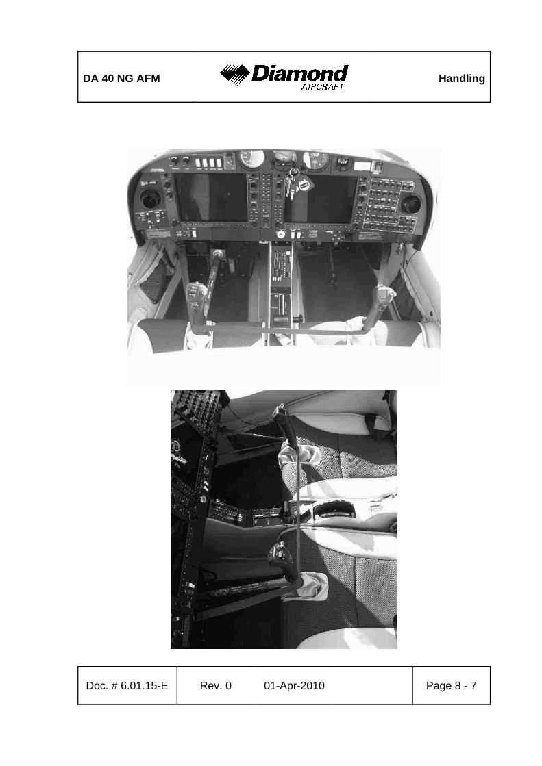
DA 40 NG AFM Handling
Doc. # 6.01.15-E Rev. 0 01-Apr-2010 Page 8 - 7
Handling DA 40 NG AFM
Page 8 - 8 Rev. 0 01-Apr-2010 Doc. # 6.01.15-E
8.4.4 MOORING
The tail fin of the airplane has a hole which can be used to tie-down the airplane to theground. Also on each wing near the wing tip, an eyelet with a metric M8 thread can beinstalled and used as tie-down points.
8.4.5 JACKING
The airplane can be jacked at the two jackpoints located on the lower side of the fuselage*sLH and RH root ribs as well as at the tail fin.
8.4.6 ALIGNMENT
For alignment push down on the tail section at the fuselage/vertical tail junction until thenose wheel is clear of the ground. With the nose wheel free, the airplane can be turnedaround the main landing gear. After turning the airplane into the correct position, releasethe tail section slowly until the nose wheel is back on the ground.
DA 40 NG AFM Handling
Doc. # 6.01.15-E Rev. 0 01-Apr-2010 Page 8 - 9
8.4.7 ROAD TRANSPORT
For transporting the airplane on the road it is recommended that an open trailer be used.All airplane components must be stored on a cushioned surface and secured to avoidany movement during transportation.
NOTEDisassembling and Assembling of the airplane is amaintenance action and requires qualified personel.
1. Fuselage:
The fuselage should stand on the main and nose landing gear. It must be ensured thatthe fuselage will not move in any direction. Furthermore, it must be ensured that thepropeller has sufficient clearance so that it cannot be damaged due to fuselage movementduring transportation.
2. Wings:
For transportation, both wings must be removed from the fuselage. To avoid any damage,the wings must be stored in an upright position on the leading edge with the root rib areapositioned on an upholstered profiled surface with a width of at least 400 mm (1.3 ft). Theoutside wing area (approximately 3 m (10 ft) from the root rib area) must be placed onan upholstered profiled surface with a minimum width of 300 mm (1 ft).
The wings must be secured to avoid any sliding movement to the rear.
3. Horizontal Stabilizer:
The horizontal stabilizer must be stored flat on the trailer and secured with straps, or inan upright position sitting on the leading edge on a profiled surface. All storing surfacesmust be upholstered with felt or cellular rubber.
Handling DA 40 NG AFM
Page 8 - 10 Rev. 0 01-Apr-2010 Doc. # 6.01.15-E
8.5 CLEANING AND CARE
CAUTIONThe airplane must be kept clean. The bright surface preventsthe structure from overheating.
CAUTIONExcessive dirt deteriorates the flight performance.
8.5.1 PAINTED SURFACES
The entire surface of the airplane is painted with a white weatherproof two componentpaint. Nevertheless, it is recommended to protect the airplane against moisture anddampness. It is also recommended not to store the airplane outside for long periods oftime.
Dirt, insects, etc. can be removed with water alone and if necessary with a mild detergent.An automotive paint cleaner can be used for stubborn spots. For best results, clean theairplane after the day's flying is ended, so that the dirt will not become ingrained.
Oil stains, exhaust stains, etc. on the lower fuselage skin can be removed with a colddetergent. Before starting, ensure that the detergent does not affect the surface finish.Use commercial automotive preservatives without silicone additives to conserve the paintfinish.
8.5.2 CANOPY AND REAR DOOR
The canopy and rear door should be cleaned with 'Plexiklar' or any other acrylic glassdetergent if available; otherwise use lukewarm water. Final cleaning should be done witha clean piece of chamois-leather or soft cloth. Never rub or polish dry acrylic glass.
DA 40 NG AFM Handling
Doc. # 6.01.15-E Rev. 0 01-Apr-2010 Page 8 - 11
8.5.3 PROPELLER
Damage and malfunctions during operation must be inspected by authorized personnel.
Surface
The manufacturer uses PU paint or acrylic paint which is resistant to almost any solvent.The blades may be treated with commercial automotive cleaning agents or preservatives.The penetration of moisture into the wooden core must be avoided by all means. Shoulddoubts arise, an appropriately rated inspector must be consulted.
8.5.4 ENGINE
Engine cleaning is part of the scheduled inspections.
8.5.5 INTERIOR SURFACES
The interior should be cleaned using a vacuum cleaner. All loose items (pens, bags etc.)should be removed or properly stored and secured.
All instruments can be cleaned using a soft dry cloth, plastic surfaces should be wipedclean using a damp cloth without any cleaning agents.
CAUTIONThe PFD and MFD displays use a lens coated with a specialanti-reflective coating that is very sensitive to skin oils, waxes,and abrasive cleaners. CLEANERS CONTAINING AMMONIAWILL HARM THE ANTI-REFLECTIVE COATING. It is veryimportant to clean the lens using a clean, lint-free cloth andan eyeglass lens cleaner that is specified as safe foranti-reflective coatings.
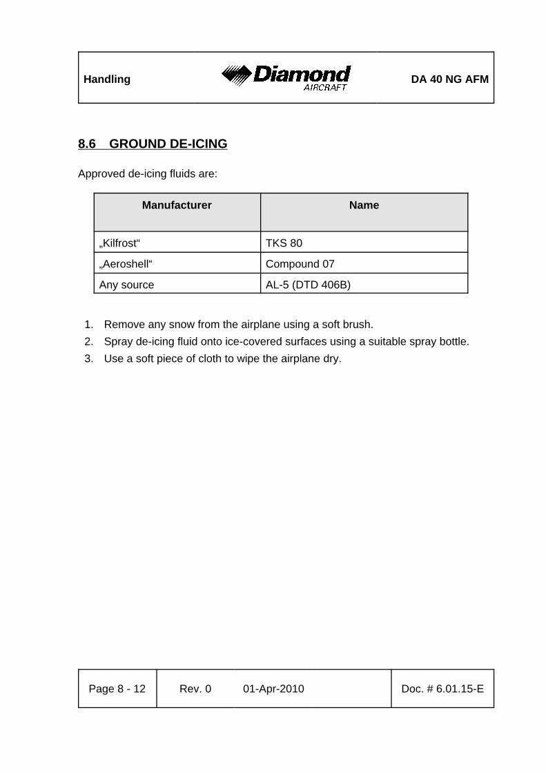
Handling DA 40 NG AFM
Page 8 - 12 Rev. 0 01-Apr-2010 Doc. # 6.01.15-E
8.6 GROUND DE-ICING
Approved de-icing fluids are:
Manufacturer Name
„Kilfrost“ TKS 80
„Aeroshell“ Compound 07
Any source AL-5 (DTD 406B)
1. Remove any snow from the airplane using a soft brush.2. Spray de-icing fluid onto ice-covered surfaces using a suitable spray bottle.3. Use a soft piece of cloth to wipe the airplane dry.
DA 40 NG AFM Supplements
Doc. # 6.01.15-E Rev. 0 01-Apr-2010 Page 9 - 1
CHAPTER 9SUPPLEMENTS
Page
9.1 INTRODUCTION . . . . . . . . . . . . . . . . . . . . . . . . . . . . . . . . . . . . . . . 9-29.2 LIST OF SUPPLEMENTS . . . . . . . . . . . . . . . . . . . . . . . . . . . . . . . . 9-3
Supplements DA 40 NG AFM
Page 9 - 2 Rev. 0 01-Apr-2010 Doc. # 6.01.15-E
9.1 INTRODUCTION
Chapter 9 contains information concerning additional (optional) equipment of theDA 40 NG.
Unless otherwise stated, the procedures given in the Supplements must be applied inaddition to the procedures given in the main part of the Airplane Flight Manual.
All approved supplements are listed in the List of Supplements in this Chapter.
The Airplane Flight Manual contains exactly those Supplements which correspond to theinstalled equipment according to the Equipment Inventory of Section 6.5.
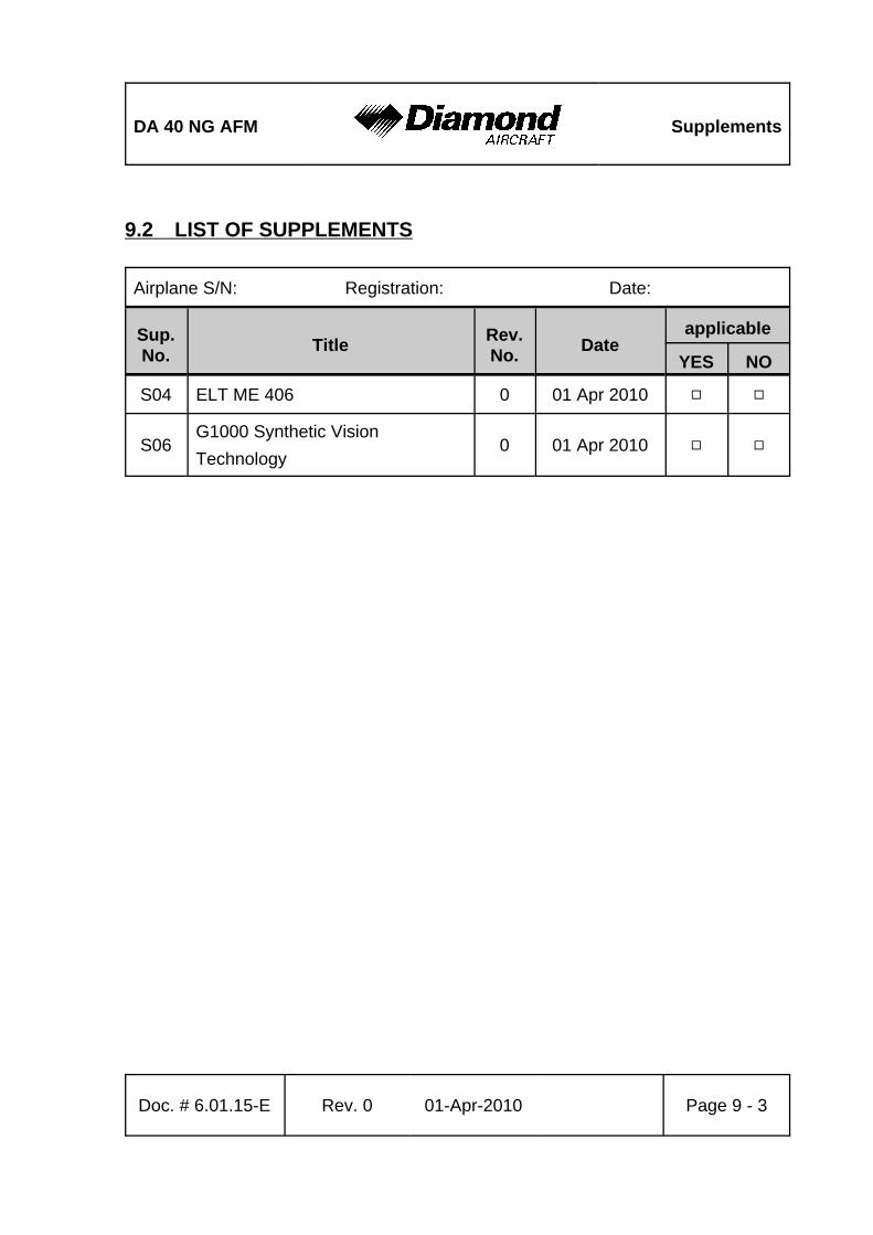
DA 40 NG AFM Supplements
Doc. # 6.01.15-E Rev. 0 01-Apr-2010 Page 9 - 3
9.2 LIST OF SUPPLEMENTS
Airplane S/N: Registration: Date:
Sup.No. Title Rev.
No. Dateapplicable
YES NO
S04 ELT ME 406 0 01 Apr 2010 9 9
S06G1000 Synthetic VisionTechnology
0 01 Apr 2010 9 9

Supplements DA 40 NG AFM
Page 9 - 4 Rev. 0 01-Apr-2010 Doc. # 6.01.15-E
Intentionally left blank.