Embed Size (px)
Citation preview

DA 40 NG AFM Introduction
Page 0 - 0a Rev. 3 01-Jul-2014 Doc. # 6.01.15-E
Intentionally left blank.
DA 40 NG AFM Introduction
Doc. # 6.01.15-E Rev. 3 01-Jul-2014 Page 0 - 1
FOREWORD
We congratulate you on the acquisition of your new DIAMOND DA 40 NG.
Skillful operation of an airplane increases both safety and the enjoyment of flying. Please
take the time therefore, to familiarize yourself with your new DIAMOND DA 40 NG.
This airplane may only be operated in accordance with the procedures and operating
limitations of this Airplane Flight Manual.
Before this airplane is operated for the first time, the pilot must familiarize himself with
the complete contents of this Airplane Flight Manual.
In the event that you have obtained your DIAMOND DA 40 NG second-hand, please let
us know your address, so that we can supply you with the publications necessary for the
safe operation of your airplane.
This document is protected by copyright. All associated rights, in particular those of
translation, reprinting, radio transmission, reproduction by photo-mechanical or similar
means and storing in data processing facilities, in whole or part, are reserved.
Copyright © by: DIAMOND AIRCRAFT INDUSTRIES GMBH
N.A. Otto-Strasse 5
A-2700 Wiener Neustadt, Austria
Phone. : +43-2622-26700
Fax : +43-2622-26780
E-Mail : [email protected]
Introduction DA 40 NG AFM
Page 0 - 2 Rev. 3 01-Jul-2014 Doc. # 6.01.15-E
0.1 APPROVAL
The content of approved chapters is approved by EASA. All other content is approved
by DAI under the authority of EASA DOA No. EASA.21J.052 in accordance with Part 21.
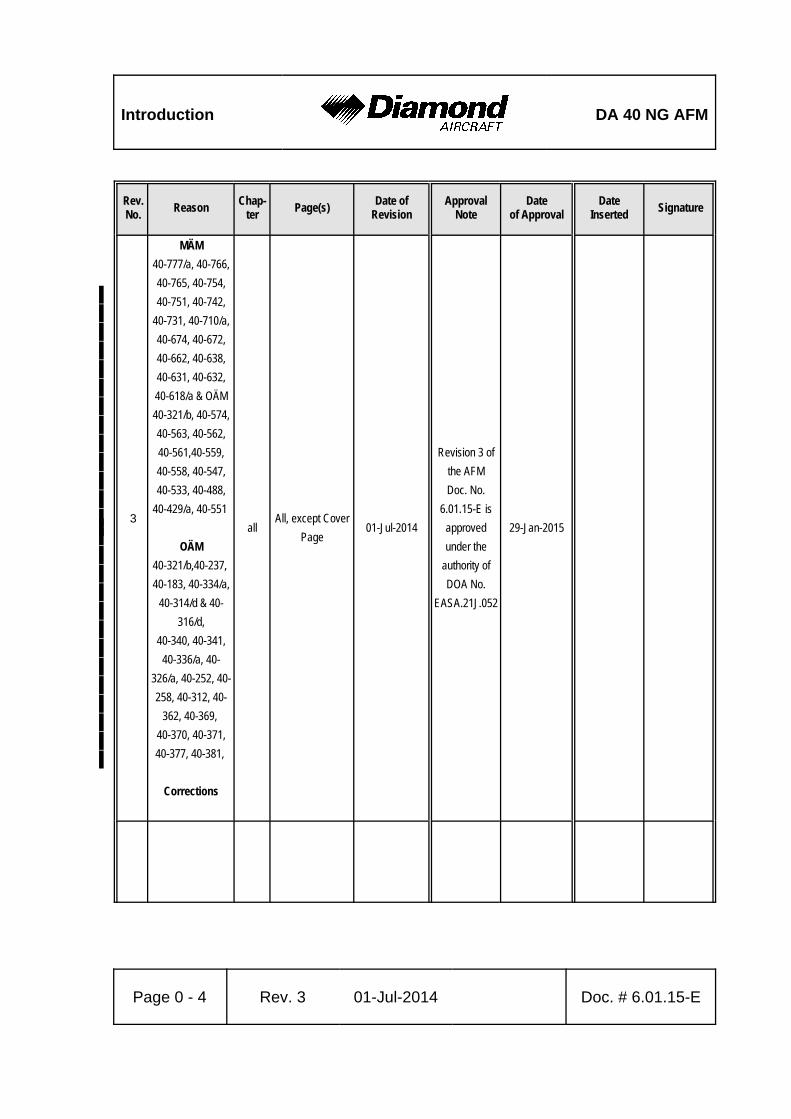
0.2 RECORD OF REVISIONS
All revisions of this manual, with the exception of
• Temporary Revisions,
• updates of the modification level (Section 1.1),
• updated mass and balance information (Section 6.3),
• updates of the Equipment Inventory (Section 6.5), and
• updates of the List of Supplements (Section 9.2)
must be recorded in the following table.
The new or amended text is indicated by a vertical black line at the left hand side of the
revised page, with the revision number and date appearing at the bottom of the page.
If pages are revised which contain information valid for your particular serial number
(modification level of the airplane, weighing data, Equipment Inventory, List of
Supplements), then this information must be transferred to the new pages in hand-writing.
Temporary Revisions are used to provide information on systems or equipment until the
next 'permanent' Revision of the Airplane Flight Manual. When a 'permanent' Revision
covers a Mandatory or Optional Design Change Advisory (MÄM or OÄM), then the
corresponding Temporary Revision is superseded. For example: if Revision 5 covers
OÄM 40-039, then the Temporary Revision TR OÄM-40-039 is superseded by the
'permanent' Revision 5.
Cover pages of Temporary Revisions, if applicable, are inserted behind the cover page
of this manual, all other pages are inserted in front of the affected pages of this manual.

DA 40 NG AFM Introduction
Doc. # 6.01.15-E Rev. 3 01-Jul-2014 Page 0 - 3
Rev.No.
ReasonChap-
terPage(s)
Date ofRevision
ApprovalNote
Dateof Approval
DateInserted
Signature
1
MÄM
40-415, 40-432,
40-440, 40-448,
40-460, 40-466,
40-447, 40-514,
OÄM
40-311, 40-313,
40-314 & 40-316,
40-321, 40-326,
40-327, 40-329,
40-330, 40-331,
40-333,
Corrections
allall, except
cover page15-Mar-2011
Revision 1 ofthe AFMDoc. No.
6.01.15-E isapproved with
EASAApproval No.
10034114.
08-Mar-2011
2
MÄM 40-434 &OÄM 40-310,
MÄM 40-451,
MÄM40-321/a
FAA- Approval
0, 1, 2,
5, 6
0-0, 0-0a, 0-3, 0-
5, 0-6, 0-9, 0-10,
1-2, 1-3, 2-24, 5-
1, 5-31, 5-32,
6-16 through 6-26
15-Jun-2011
Revision 2 ofthe AFMDoc. No.
6.01.15-E isapproved byEASA underproject No.
0010005331.
24-Nov-2011'
Introduction DA 40 NG AFM
Rev.No.
ReasonChap-
terPage(s)
Date ofRevision
ApprovalNote
Dateof Approval
DateInserted
Signature
Page 0 - 4 Rev. 3 01-Jul-2014 Doc. # 6.01.15-E
''''''''''''
3''''''''''''''
MÄM
40-777/a, 40-766,
40-765, 40-754,
40-751, 40-742,
40-731, 40-710/a,
40-674, 40-672,
40-662, 40-638,
40-631, 40-632,
40-618/a & OÄM
40-321/b, 40-574,
40-563, 40-562,
40-561,40-559,
40-558, 40-547,
40-533, 40-488,
40-429/a, 40-551
OÄM
40-321/b,40-237,
40-183, 40-334/a,
40-314/d & 40-
316/d,
40-340, 40-341,
40-336/a, 40-
326/a, 40-252, 40-
258, 40-312, 40-
362, 40-369,
40-370, 40-371,
40-377, 40-381,
Corrections
allAll, except Cover
Page01-Jul-2014
Revision 3 of
the AFM
Doc. No.
6.01.15-E is
approved
under the
authority of
DOA No.
EASA.21J.052
29-Jan-2015'
DA 40 NG AFM Introduction
Doc. # 6.01.15-E Rev. 3 01-Jul-2014 Page 0 - 5
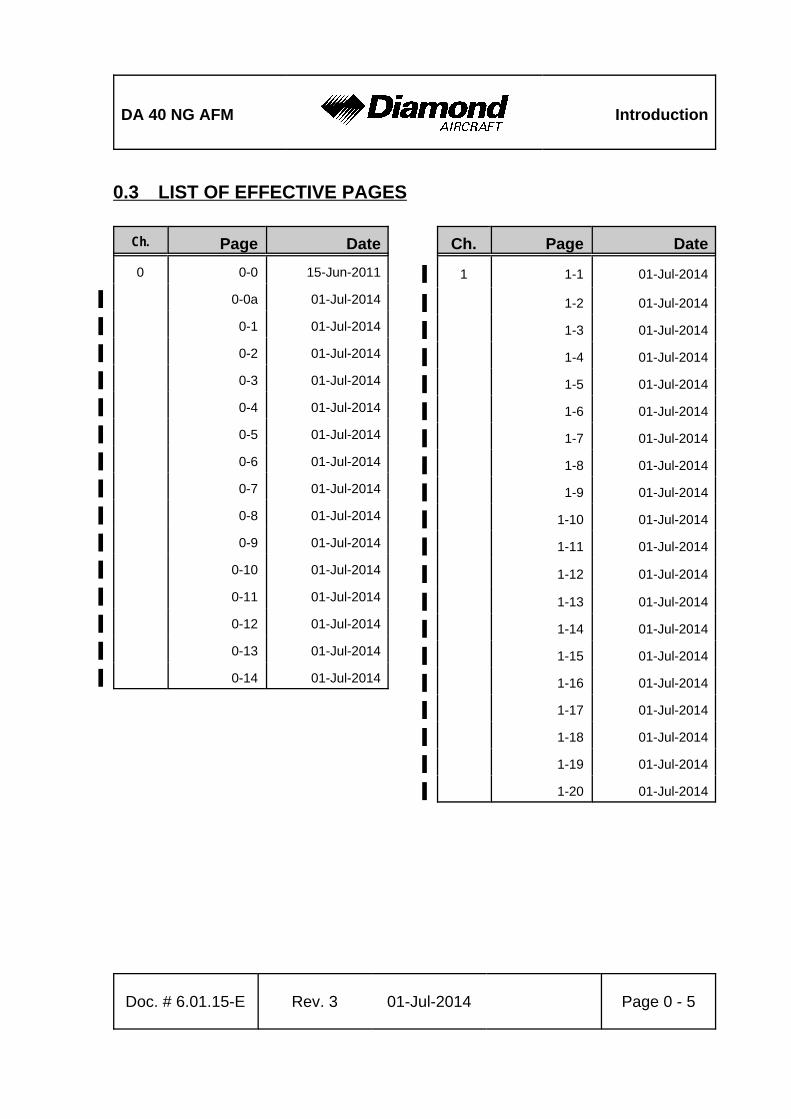
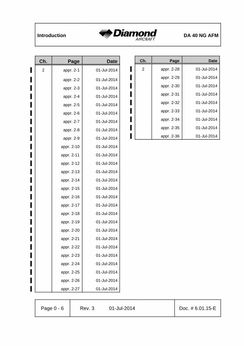
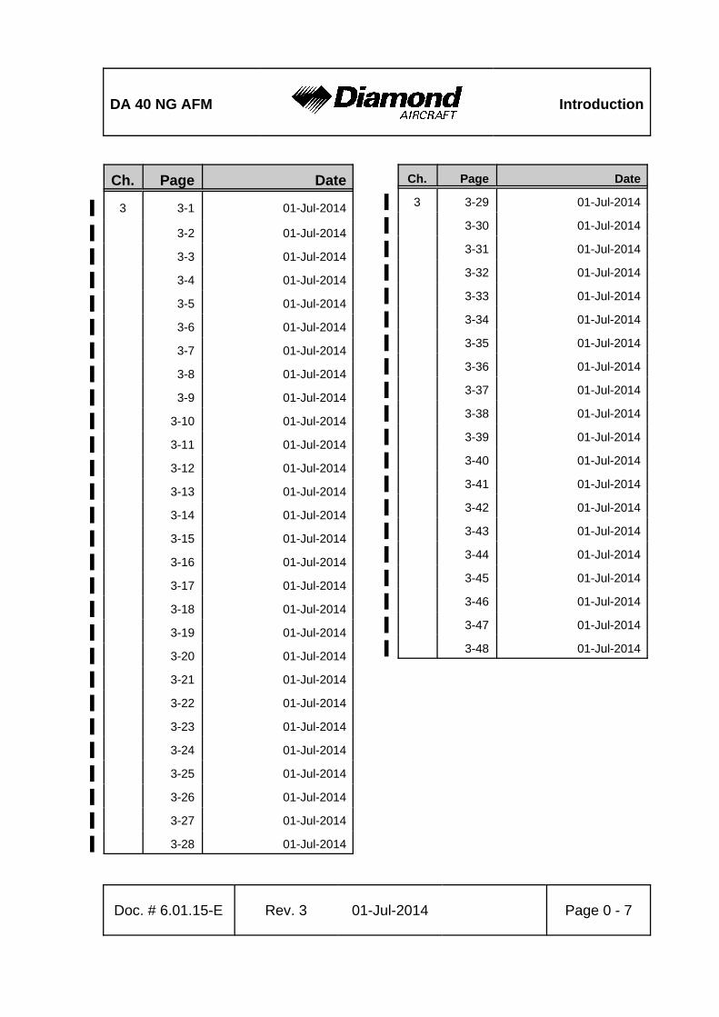
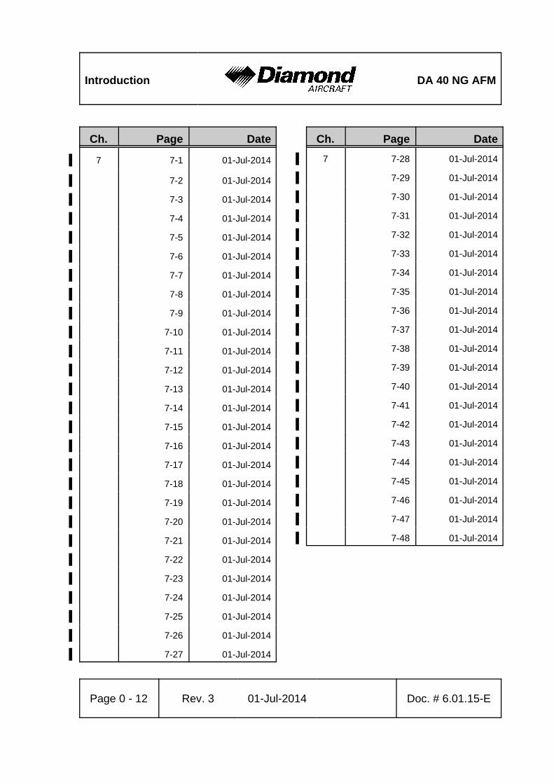
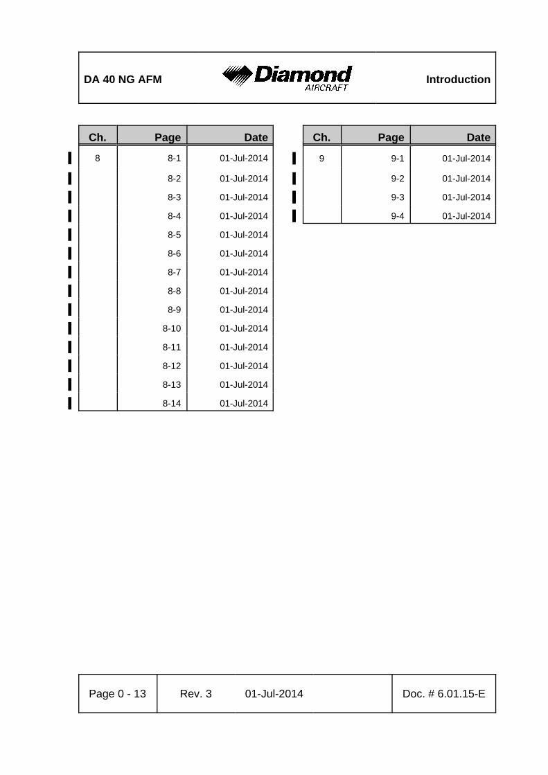
0.3 LIST OF EFFECTIVE PAGES
Ch. Page Date
0 0-0 15-Jun-2011
0-0a 01-Jul-2014'
0-1 01-Jul-2014'
0-2 01-Jul-2014'
0-3 01-Jul-2014'
0-4 01-Jul-2014'
0-5 01-Jul-2014'
0-6 01-Jul-2014'
0-7 01-Jul-2014'
0-8 01-Jul-2014'
0-9 01-Jul-2014'
0-10 01-Jul-2014'
0-11 01-Jul-2014'
0-12 01-Jul-2014'
0-13 01-Jul-2014'
0-14 01-Jul-2014'
Ch. Page Date
1 1-1 01-Jul-2014'
1-2 01-Jul-2014'
1-3 01-Jul-2014'
1-4 01-Jul-2014'
1-5 01-Jul-2014'
1-6 01-Jul-2014'
1-7 01-Jul-2014'
1-8 01-Jul-2014'
1-9 01-Jul-2014'
1-10 01-Jul-2014'
1-11 01-Jul-2014'
1-12 01-Jul-2014'
1-13 01-Jul-2014'
1-14 01-Jul-2014'
1-15 01-Jul-2014'
1-16 01-Jul-2014'
1-17 01-Jul-2014'
1-18 01-Jul-2014'
1-19 01-Jul-2014'
1-20 01-Jul-2014'
Introduction DA 40 NG AFM
Page 0 - 6 Rev. 3 01-Jul-2014 Doc. # 6.01.15-E
Ch. Page Date
2 appr. 2-1 01-Jul-2014'
appr. 2-2 01-Jul-2014'
appr. 2-3 01-Jul-2014'
appr. 2-4 01-Jul-2014'
appr. 2-5 01-Jul-2014'
appr. 2-6 01-Jul-2014'
appr. 2-7 01-Jul-2014'
appr. 2-8 01-Jul-2014'
appr. 2-9 01-Jul-2014'
appr. 2-10 01-Jul-2014'
appr. 2-11 01-Jul-2014'
appr. 2-12 01-Jul-2014'
appr. 2-13 01-Jul-2014'
appr. 2-14 01-Jul-2014'
appr. 2-15 01-Jul-2014'
appr. 2-16 01-Jul-2014'
appr. 2-17 01-Jul-2014'
appr. 2-18 01-Jul-2014'
appr. 2-19 01-Jul-2014'
appr. 2-20 01-Jul-2014'
appr. 2-21 01-Jul-2014'
appr. 2-22 01-Jul-2014'
appr. 2-23 01-Jul-2014'
appr. 2-24 01-Jul-2014'
appr. 2-25 01-Jul-2014'
appr. 2-26 01-Jul-2014'
appr. 2-27 01-Jul-2014'
Ch. Page Date
2 appr. 2-28 01-Jul-2014'
appr. 2-29 01-Jul-2014'
appr. 2-30 01-Jul-2014'
appr. 2-31 01-Jul-2014'
appr. 2-32 01-Jul-2014'
appr. 2-33 01-Jul-2014'
appr. 2-34 01-Jul-2014'
appr. 2-35 01-Jul-2014'
appr. 2-36 01-Jul-2014'
DA 40 NG AFM Introduction
Doc. # 6.01.15-E Rev. 3 01-Jul-2014 Page 0 - 7
Ch. Page Date
3 3-1 01-Jul-2014'
3-2 01-Jul-2014'
3-3 01-Jul-2014'
3-4 01-Jul-2014'
3-5 01-Jul-2014'
3-6 01-Jul-2014'
3-7 01-Jul-2014'
3-8 01-Jul-2014'
3-9 01-Jul-2014'
3-10 01-Jul-2014'
3-11 01-Jul-2014'
3-12 01-Jul-2014'
3-13 01-Jul-2014'
3-14 01-Jul-2014'
3-15 01-Jul-2014'
3-16 01-Jul-2014'
3-17 01-Jul-2014'
3-18 01-Jul-2014'
3-19 01-Jul-2014'
3-20 01-Jul-2014'
3-21 01-Jul-2014'
3-22 01-Jul-2014'
3-23 01-Jul-2014'
3-24 01-Jul-2014'
3-25 01-Jul-2014'
3-26 01-Jul-2014'
3-27 01-Jul-2014'
3-28 01-Jul-2014'
Ch. Page Date
3 3-29 01-Jul-2014'
3-30 01-Jul-2014'
3-31 01-Jul-2014'
3-32 01-Jul-2014'
3-33 01-Jul-2014'
3-34 01-Jul-2014'
3-35 01-Jul-2014'
3-36 01-Jul-2014'
3-37 01-Jul-2014'
3-38 01-Jul-2014'
3-39 01-Jul-2014'
3-40 01-Jul-2014'
3-41 01-Jul-2014'
3-42 01-Jul-2014'
3-43 01-Jul-2014'
3-44 01-Jul-2014'
3-45 01-Jul-2014'
3-46 01-Jul-2014'
3-47 01-Jul-2014'
3-48 01-Jul-2014'
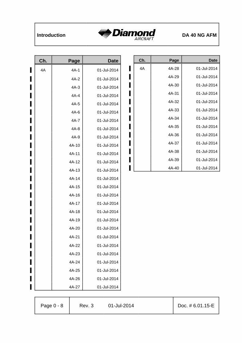
Introduction DA 40 NG AFM
Page 0 - 8 Rev. 3 01-Jul-2014 Doc. # 6.01.15-E
Ch. Page Date
4A 4A-1 01-Jul-2014'
4A-2 01-Jul-2014'
4A-3 01-Jul-2014'
4A-4 01-Jul-2014'
4A-5 01-Jul-2014'
4A-6 01-Jul-2014'
4A-7 01-Jul-2014'
4A-8 01-Jul-2014'
4A-9 01-Jul-2014'
4A-10 01-Jul-2014'
4A-11 01-Jul-2014'
4A-12 01-Jul-2014'
4A-13 01-Jul-2014'
4A-14 01-Jul-2014'
4A-15 01-Jul-2014'
4A-16 01-Jul-2014'
4A-17 01-Jul-2014'
4A-18 01-Jul-2014'
4A-19 01-Jul-2014'
4A-20 01-Jul-2014'
4A-21 01-Jul-2014'
4A-22 01-Jul-2014'
4A-23 01-Jul-2014'
4A-24 01-Jul-2014'
4A-25 01-Jul-2014'
4A-26 01-Jul-2014'
4A-27 01-Jul-2014'
Ch. Page Date
4A 4A-28 01-Jul-2014'
4A-29 01-Jul-2014'
4A-30 01-Jul-2014'
4A-31 01-Jul-2014'
4A-32 01-Jul-2014'
4A-33 01-Jul-2014'
4A-34 01-Jul-2014'
4A-35 01-Jul-2014'
4A-36 01-Jul-2014'
4A-37 01-Jul-2014'
4A-38 01-Jul-2014'
4A-39 01-Jul-2014'
4A-40 01-Jul-2014'
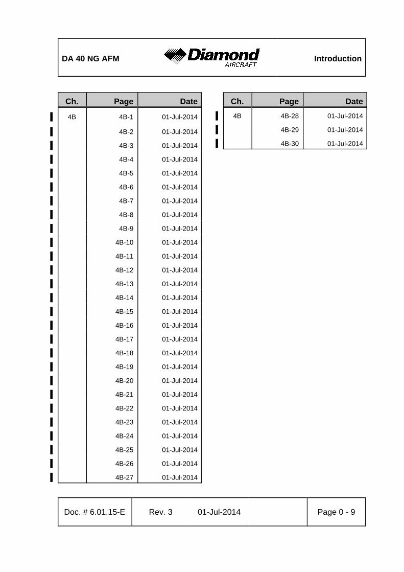
DA 40 NG AFM Introduction
Doc. # 6.01.15-E Rev. 3 01-Jul-2014 Page 0 - 9
Ch. Page Date
4B 4B-1 01-Jul-2014'
4B-2 01-Jul-2014'
4B-3 01-Jul-2014'
4B-4 01-Jul-2014'
4B-5 01-Jul-2014'
4B-6 01-Jul-2014'
4B-7 01-Jul-2014'
4B-8 01-Jul-2014'
4B-9 01-Jul-2014'
4B-10 01-Jul-2014'
4B-11 01-Jul-2014'
4B-12 01-Jul-2014'
4B-13 01-Jul-2014'
4B-14 01-Jul-2014'
4B-15 01-Jul-2014'
4B-16 01-Jul-2014'
4B-17 01-Jul-2014'
4B-18 01-Jul-2014'
4B-19 01-Jul-2014'
4B-20 01-Jul-2014'
4B-21 01-Jul-2014'
4B-22 01-Jul-2014'
4B-23 01-Jul-2014'
4B-24 01-Jul-2014'
4B-25 01-Jul-2014'
4B-26 01-Jul-2014'
4B-27 01-Jul-2014'
Ch. Page Date
4B 4B-28 01-Jul-2014'
4B-29 01-Jul-2014'
4B-30 01-Jul-2014'
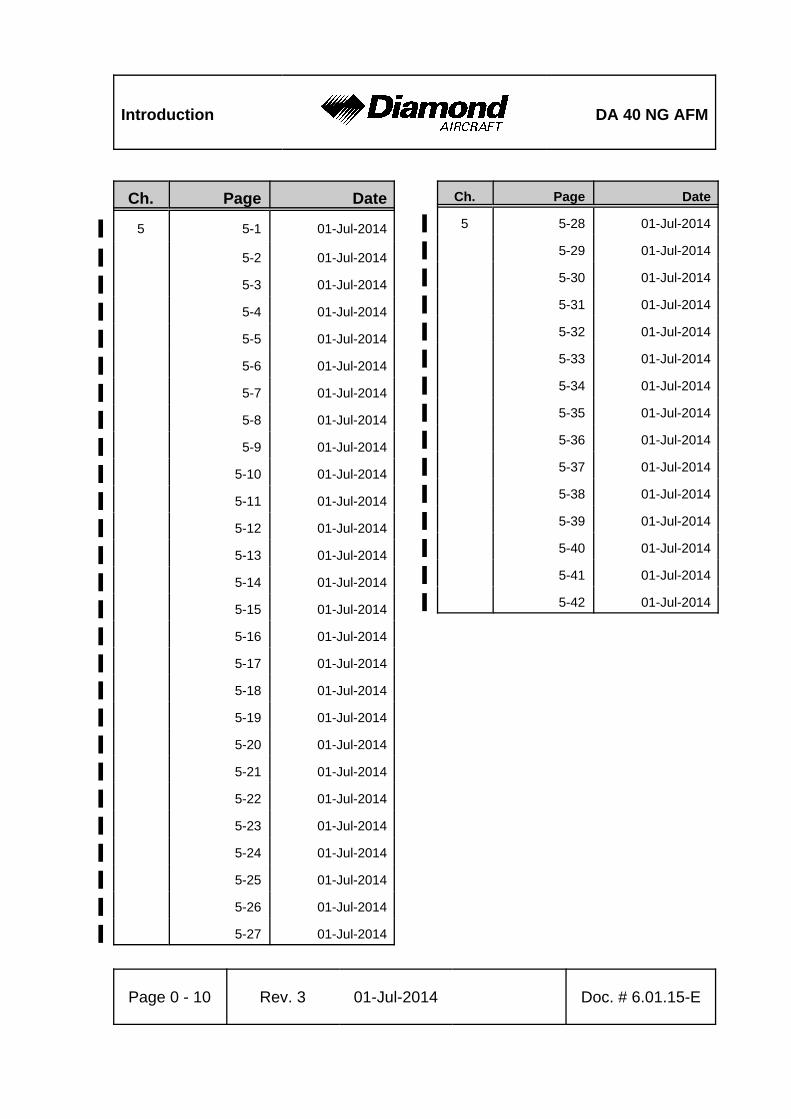
Introduction DA 40 NG AFM
Page 0 - 10 Rev. 3 01-Jul-2014 Doc. # 6.01.15-E
Ch. Page Date
5 5-1 01-Jul-2014'
5-2 01-Jul-2014'
5-3 01-Jul-2014'
5-4 01-Jul-2014'
5-5 01-Jul-2014'
5-6 01-Jul-2014'
5-7 01-Jul-2014'
5-8 01-Jul-2014'
5-9 01-Jul-2014'
5-10 01-Jul-2014'
5-11 01-Jul-2014'
5-12 01-Jul-2014'
5-13 01-Jul-2014'
5-14 01-Jul-2014'
5-15 01-Jul-2014'
5-16 01-Jul-2014'
5-17 01-Jul-2014'
5-18 01-Jul-2014'
5-19 01-Jul-2014'
5-20 01-Jul-2014'
5-21 01-Jul-2014'
5-22 01-Jul-2014'
5-23 01-Jul-2014'
5-24 01-Jul-2014'
5-25 01-Jul-2014'
5-26 01-Jul-2014'
5-27 01-Jul-2014'
Ch. Page Date
5 5-28 01-Jul-2014'
5-29 01-Jul-2014'
5-30 01-Jul-2014'
5-31 01-Jul-2014'
5-32 01-Jul-2014'
5-33 01-Jul-2014'
5-34 01-Jul-2014'
5-35 01-Jul-2014'
5-36 01-Jul-2014'
5-37 01-Jul-2014'
5-38 01-Jul-2014'
5-39 01-Jul-2014'
5-40 01-Jul-2014'
5-41 01-Jul-2014'
5-42 01-Jul-2014'
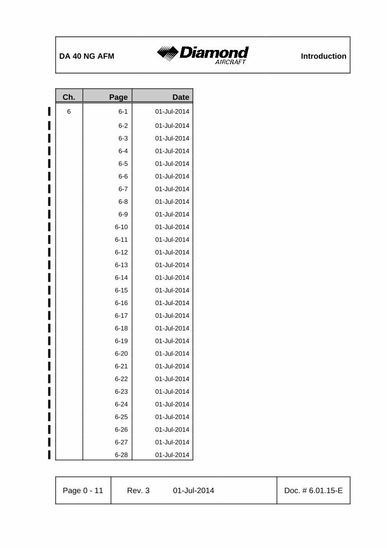
DA 40 NG AFM Introduction
Page 0 - 11 Rev. 3 01-Jul-2014 Doc. # 6.01.15-E
Ch. Page Date
6 6-1 01-Jul-2014'
6-2 01-Jul-2014'
6-3 01-Jul-2014'
6-4 01-Jul-2014'
6-5 01-Jul-2014'
6-6 01-Jul-2014'
6-7 01-Jul-2014'
6-8 01-Jul-2014'
6-9 01-Jul-2014'
6-10 01-Jul-2014'
6-11 01-Jul-2014'
6-12 01-Jul-2014'
6-13 01-Jul-2014'
6-14 01-Jul-2014'
6-15 01-Jul-2014'
6-16 01-Jul-2014'
6-17 01-Jul-2014'
6-18 01-Jul-2014'
6-19 01-Jul-2014'
6-20 01-Jul-2014'
6-21 01-Jul-2014'
6-22 01-Jul-2014'
6-23 01-Jul-2014'
6-24 01-Jul-2014'
6-25 01-Jul-2014'
6-26 01-Jul-2014'
6-27 01-Jul-2014'
6-28 01-Jul-2014'
Introduction DA 40 NG AFM
Page 0 - 12 Rev. 3 01-Jul-2014 Doc. # 6.01.15-E
Ch. Page Date
7 7-1 01-Jul-2014'
7-2 01-Jul-2014'
7-3 01-Jul-2014'
7-4 01-Jul-2014'
7-5 01-Jul-2014'
7-6 01-Jul-2014'
7-7 01-Jul-2014'
7-8 01-Jul-2014'
7-9 01-Jul-2014'
7-10 01-Jul-2014'
7-11 01-Jul-2014'
7-12 01-Jul-2014'
7-13 01-Jul-2014'
7-14 01-Jul-2014'
7-15 01-Jul-2014'
7-16 01-Jul-2014'
7-17 01-Jul-2014'
7-18 01-Jul-2014'
7-19 01-Jul-2014'
7-20 01-Jul-2014'
7-21 01-Jul-2014'
7-22 01-Jul-2014'
7-23 01-Jul-2014'
7-24 01-Jul-2014'
7-25 01-Jul-2014'
7-26 01-Jul-2014'
7-27 01-Jul-2014'
Ch. Page Date
7 7-28 01-Jul-2014'
7-29 01-Jul-2014'
7-30 01-Jul-2014'
7-31 01-Jul-2014'
7-32 01-Jul-2014'
7-33 01-Jul-2014'
7-34 01-Jul-2014'
7-35 01-Jul-2014'
7-36 01-Jul-2014'
7-37 01-Jul-2014'
7-38 01-Jul-2014'
7-39 01-Jul-2014'
7-40 01-Jul-2014'
7-41 01-Jul-2014'
7-42 01-Jul-2014'
7-43 01-Jul-2014'
7-44 01-Jul-2014'
7-45 01-Jul-2014'
7-46 01-Jul-2014'
7-47 01-Jul-2014'
7-48 01-Jul-2014'
DA 40 NG AFM Introduction
Page 0 - 13 Rev. 3 01-Jul-2014 Doc. # 6.01.15-E
Ch. Page Date
8 8-1 01-Jul-2014'
8-2 01-Jul-2014'
8-3 01-Jul-2014'
8-4 01-Jul-2014'
8-5 01-Jul-2014'
8-6 01-Jul-2014'
8-7 01-Jul-2014'
8-8 01-Jul-2014'
8-9 01-Jul-2014'
8-10 01-Jul-2014'
8-11 01-Jul-2014'
8-12 01-Jul-2014'
8-13 01-Jul-2014'
8-14 01-Jul-2014'
Ch. Page Date
9 9-1 01-Jul-2014'
9-2 01-Jul-2014'
' 9-3 01-Jul-2014'
' 9-4 01-Jul-2014'
Introduction DA 40 NG AFM
Page 0 - 14 Rev. 3 01-Jul-2014 Doc. # 6.01.15-E
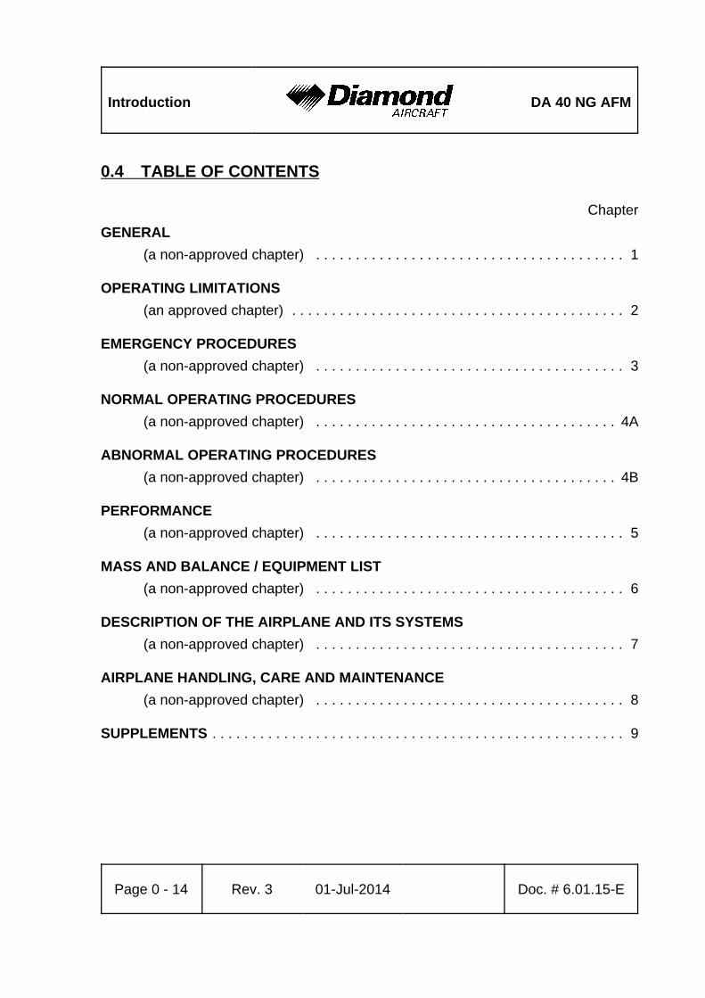
0.4 TABLE OF CONTENTS
Chapter
GENERAL
(a non-approved chapter) . . . . . . . . . . . . . . . . . . . . . . . . . . . . . . . . . . . . . . . 1
OPERATING LIMITATIONS
(an approved chapter) . . . . . . . . . . . . . . . . . . . . . . . . . . . . . . . . . . . . . . . . . . 2
EMERGENCY PROCEDURES
(a non-approved chapter) . . . . . . . . . . . . . . . . . . . . . . . . . . . . . . . . . . . . . . . 3
NORMAL OPERATING PROCEDURES
(a non-approved chapter) . . . . . . . . . . . . . . . . . . . . . . . . . . . . . . . . . . . . . . 4A
ABNORMAL OPERATING PROCEDURES
(a non-approved chapter) . . . . . . . . . . . . . . . . . . . . . . . . . . . . . . . . . . . . . . 4B
PERFORMANCE
(a non-approved chapter) . . . . . . . . . . . . . . . . . . . . . . . . . . . . . . . . . . . . . . . 5
MASS AND BALANCE / EQUIPMENT LIST
(a non-approved chapter) . . . . . . . . . . . . . . . . . . . . . . . . . . . . . . . . . . . . . . . 6
DESCRIPTION OF THE AIRPLANE AND ITS SYSTEMS
(a non-approved chapter) . . . . . . . . . . . . . . . . . . . . . . . . . . . . . . . . . . . . . . . 7
AIRPLANE HANDLING, CARE AND MAINTENANCE
(a non-approved chapter) . . . . . . . . . . . . . . . . . . . . . . . . . . . . . . . . . . . . . . . 8
SUPPLEMENTS . . . . . . . . . . . . . . . . . . . . . . . . . . . . . . . . . . . . . . . . . . . . . . . . . . . . 9

DA 40 NG AFM General
Doc. # 6.01.15-E Rev. 3 01-Jul-2014 Page 1 - 1
CHAPTER 1
GENERAL
Page
1.1 INTRODUCTION . . . . . . . . . . . . . . . . . . . . . . . . . . . . . . . . . . . . . . . 1-2
1.2 CERTIFICATION BASIS . . . . . . . . . . . . . . . . . . . . . . . . . . . . . . . . . 1-4
1.3 WARNINGS, CAUTIONS AND NOTES . . . . . . . . . . . . . . . . . . . . . 1-4
1.4 DIMENSIONS . . . . . . . . . . . . . . . . . . . . . . . . . . . . . . . . . . . . . . . . . 1-5
1.5 DEFINITIONS AND ABBREVIATIONS . . . . . . . . . . . . . . . . . . . . . . 1-7
1.6 UNITS OF MEASUREMENT . . . . . . . . . . . . . . . . . . . . . . . . . . . . . 1-15
1.6.1 CONVERSION FACTORS . . . . . . . . . . . . . . . . . . . . . . . . . 1-15
1.6.2 CONVERSION CHART LITER / US GALLON . . . . . . . . . . 1-17
1.7 THREE-VIEW DRAWING . . . . . . . . . . . . . . . . . . . . . . . . . . . . . . . 1-18
1.8 SOURCE DOCUMENTATION . . . . . . . . . . . . . . . . . . . . . . . . . . . 1-19
1.8.1 ENGINE AND ENGINE INSTRUMENTS . . . . . . . . . . . . . . . 1-19
1.8.2 PROPELLER . . . . . . . . . . . . . . . . . . . . . . . . . . . . . . . . . . . . 1-20
General DA 40 NG AFM
Page 1 - 2 Rev. 3 01-Jul-2014 Doc. # 6.01.15-E
1.1 INTRODUCTION
This Airplane Flight Manual has been prepared in order to provide pilots and instructors
with all the information required for the safe and efficient operation of the airplane.
The Airplane Flight Manual includes all the data which must be made available to the pilot
according to the JAR-23 requirement. Beyond this, it contains further data and operating
instructions which, in the manufacturer’s opinion, could be of value to the pilot.
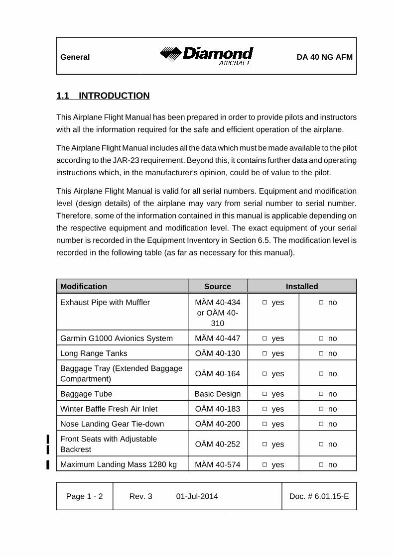
This Airplane Flight Manual is valid for all serial numbers. Equipment and modification
level (design details) of the airplane may vary from serial number to serial number.
Therefore, some of the information contained in this manual is applicable depending on
the respective equipment and modification level. The exact equipment of your serial
number is recorded in the Equipment Inventory in Section 6.5. The modification level is
recorded in the following table (as far as necessary for this manual).
Modification Source Installed
Exhaust Pipe with Muffler MÄM 40-434or OÄM 40-
310
9 yes 9 no
Garmin G1000 Avionics System MÄM 40-447 9 yes 9 no
Long Range Tanks OÄM 40-130 9 yes 9 no
Baggage Tray (Extended BaggageCompartment)
OÄM 40-164 9 yes 9 no
Baggage Tube Basic Design 9 yes 9 no
Winter Baffle Fresh Air Inlet OÄM 40-183 9 yes 9 no
Nose Landing Gear Tie-down OÄM 40-200 9 yes 9 no
Front Seats with Adjustable%Backrest%
OÄM 40-252 9 yes 9 no
Maximum Landing Mass 1280 kg% MÄM 40-574% 9 yes% 9 no%
DA 40 NG AFM General
Modification Source Installed
Doc. # 6.01.15-E Rev. 3 01-Jul-2014 Page 1 - 3
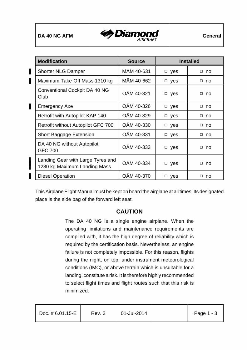
Shorter NLG Damper% MÄM 40-631% 9 yes% 9 no%
Maximum Take-Off Mass 1310 kg% MÄM 40-662% 9 yes% 9 no%
Conventional Cockpit DA 40 NGClub
OÄM 40-321 9 yes 9 no
Emergency Axe% OÄM 40-326% 9 yes% 9 no%
Retrofit with Autopilot KAP 140 OÄM 40-329 9 yes 9 no
Retrofit without Autopilot GFC 700 OÄM 40-330 9 yes 9 no
Short Baggage Extension OÄM 40-331 9 yes 9 no
DA 40 NG without AutopilotGFC 700
OÄM 40-333 9 yes 9 no
Landing Gear with Large Tyres and%1280 kg Maximum Landing Mass%
OÄM 40-334% 9 yes% 9 no%
Diesel Operation% OÄM 40-370% 9 yes% 9 no%
This Airplane Flight Manual must be kept on board the airplane at all times. Its designated
place is the side bag of the forward left seat.
CAUTION
The DA 40 NG is a single engine airplane. When the
operating limitations and maintenance requirements are
complied with, it has the high degree of reliability which is
required by the certification basis. Nevertheless, an engine
failure is not completely impossible. For this reason, flights
during the night, on top, under instrument meteorological
conditions (IMC), or above terrain which is unsuitable for a
landing, constitute a risk. It is therefore highly recommended
to select flight times and flight routes such that this risk is
minimized.
General DA 40 NG AFM
Page 1 - 4 Rev. 3 01-Jul-2014 Doc. # 6.01.15-E
1.2 CERTIFICATION BASIS
This airplane has been type certified in accordance with the procedures established by
EASA. The certification basis is JAR-23, published on 11-Mar-1994 and additional
requirements as laid down in CRI A-01.
1.3 WARNINGS, CAUTIONS AND NOTES
Special statements in the Airplane Flight Manual concerning the safety or operation of
the airplane are highlighted by being prefixed by one of the following terms:
WARNING
means that the non-observation of the corresponding
procedure leads to an immediate or important degradation
in flight safety.
CAUTION
means that the non-observation of the corresponding
procedure leads to a minor or to a more or less long term
degradation in flight safety.
NOTE
draws the attention to any special item not directly related to
safety but which is important or unusual.
DA 40 NG AFM General
Doc. # 6.01.15-E Rev. 3 01-Jul-2014 Page 1 - 5
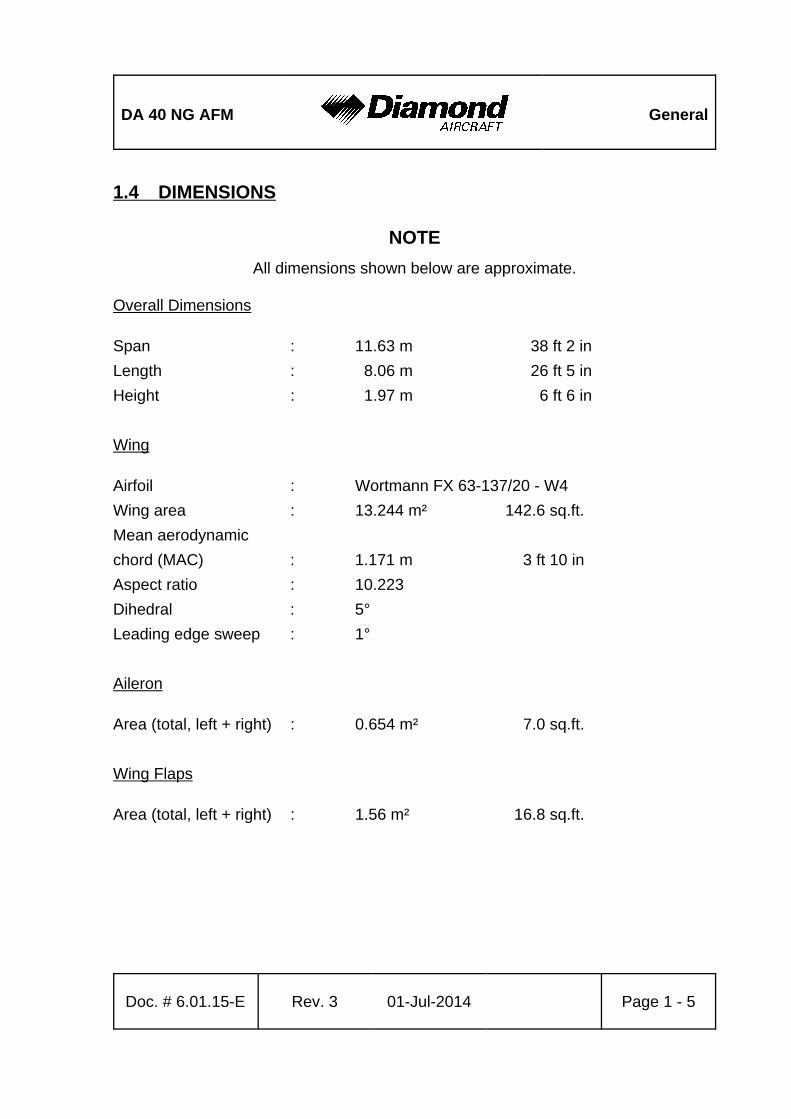
1.4 DIMENSIONS
NOTE
All dimensions shown below are approximate.
Overall Dimensions
Span : 11.63 m 38 ft 2 in
Length : 8.06 m 26 ft 5 in
Height : 1.97 m 6 ft 6 in
Wing
Airfoil : Wortmann FX 63-137/20 - W4
Wing area : 13.244 m² 142.6 sq.ft.
Mean aerodynamic
chord (MAC) : 1.171 m 3 ft 10 in
Aspect ratio : 10.223
Dihedral : 5°
Leading edge sweep : 1°
Aileron
Area (total, left + right) : 0.654 m² 7.0 sq.ft.
Wing Flaps
Area (total, left + right) : 1.56 m² 16.8 sq.ft.
General DA 40 NG AFM
Page 1 - 6 Rev. 3 01-Jul-2014 Doc. # 6.01.15-E
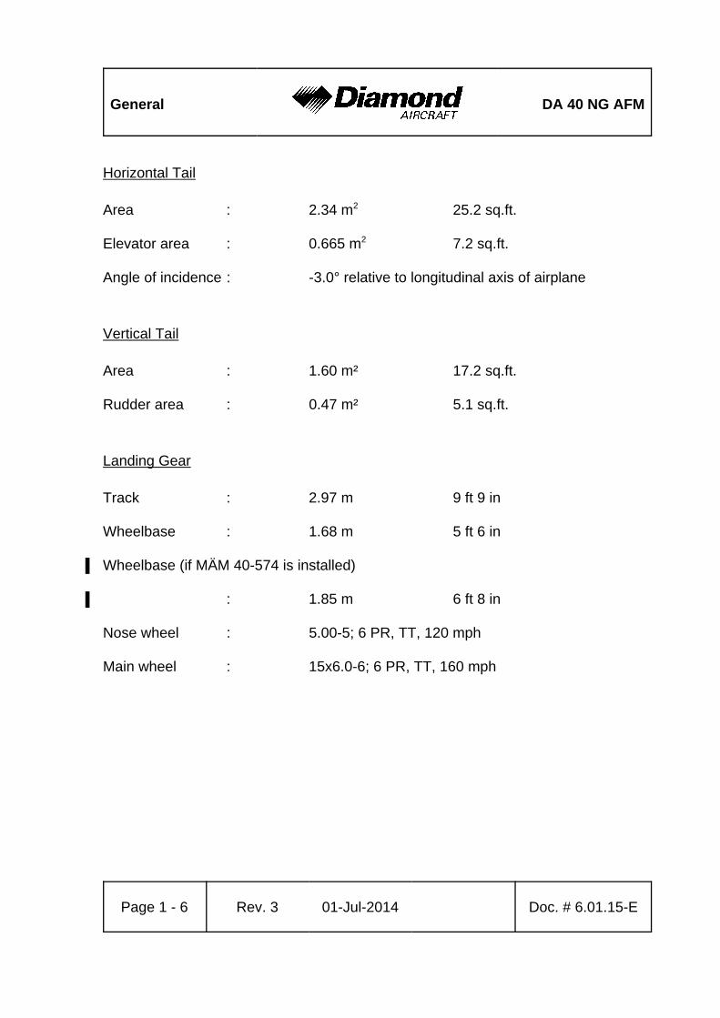
Horizontal Tail
Area : 2.34 m2 25.2 sq.ft.
Elevator area : 0.665 m2 7.2 sq.ft.
Angle of incidence : -3.0° relative to longitudinal axis of airplane
Vertical Tail
Area : 1.60 m² 17.2 sq.ft.
Rudder area : 0.47 m² 5.1 sq.ft.
Landing Gear
Track : 2.97 m 9 ft 9 in
Wheelbase : 1.68 m 5 ft 6 in
Wheelbase (if MÄM 40-574 is installed)%
: 1.85 m 6 ft 8 in%
Nose wheel : 5.00-5; 6 PR, TT, 120 mph
Main wheel : 15x6.0-6; 6 PR, TT, 160 mph
DA 40 NG AFM General
Doc. # 6.01.15-E Rev. 3 01-Jul-2014 Page 1 - 7
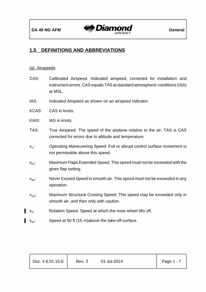
1.5 DEFINITIONS AND ABBREVIATIONS
(a) Airspeeds
CAS: Calibrated Airspeed. Indicated airspeed, corrected for installation and
instrument errors. CAS equals TAS at standard atmospheric conditions (ISA)
at MSL.
IAS: Indicated Airspeed as shown on an airspeed indicator.
KCAS: CAS in knots.
KIAS: IAS in knots.
TAS: True Airspeed. The speed of the airplane relative to the air. TAS is CAS
corrected for errors due to altitude and temperature.
vO: Operating Maneuvering Speed. Full or abrupt control surface movement is
not permissible above this speed.
vFE: Maximum Flaps Extended Speed. This speed must not be exceeded with the
given flap setting.
vNE: Never Exceed Speed in smooth air. This speed must not be exceeded in any
operation.
vNO: Maximum Structural Cruising Speed. This speed may be exceeded only in
smooth air, and then only with caution.
vR: Rotation Speed. Speed at which the nose wheel lifts off.%
v50: Speed at 50 ft (15 m)above the take-off surface.%
General DA 40 NG AFM
Page 1 - 8 Rev. 3 01-Jul-2014 Doc. # 6.01.15-E
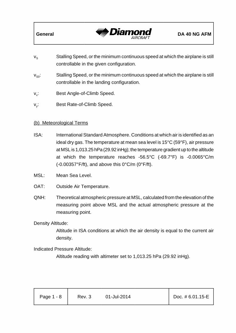
vS Stalling Speed, or the minimum continuous speed at which the airplane is still
controllable in the given configuration.
vS0: Stalling Speed, or the minimum continuous speed at which the airplane is still
controllable in the landing configuration.
vx: Best Angle-of-Climb Speed.
vy: Best Rate-of-Climb Speed.
(b) Meteorological Terms
ISA: International Standard Atmosphere. Conditions at which air is identified as an
ideal dry gas. The temperature at mean sea level is 15°C (59°F), air pressure
at MSL is 1,013.25 hPa (29.92 inHg); the temperature gradient up to the altitude
at which the temperature reaches -56.5°C (-69.7°F) is -0.0065°C/m
(-0.00357°F/ft), and above this 0°C/m (0°F/ft).
MSL: Mean Sea Level.
OAT: Outside Air Temperature.
QNH: Theoretical atmospheric pressure at MSL, calculated from the elevation of the
measuring point above MSL and the actual atmospheric pressure at the
measuring point.
Density Altitude:
Altitude in ISA conditions at which the air density is equal to the current air
density.
Indicated Pressure Altitude:
Altitude reading with altimeter set to 1,013.25 hPa (29.92 inHg).
DA 40 NG AFM General
Doc. # 6.01.15-E Rev. 3 01-Jul-2014 Page 1 - 9
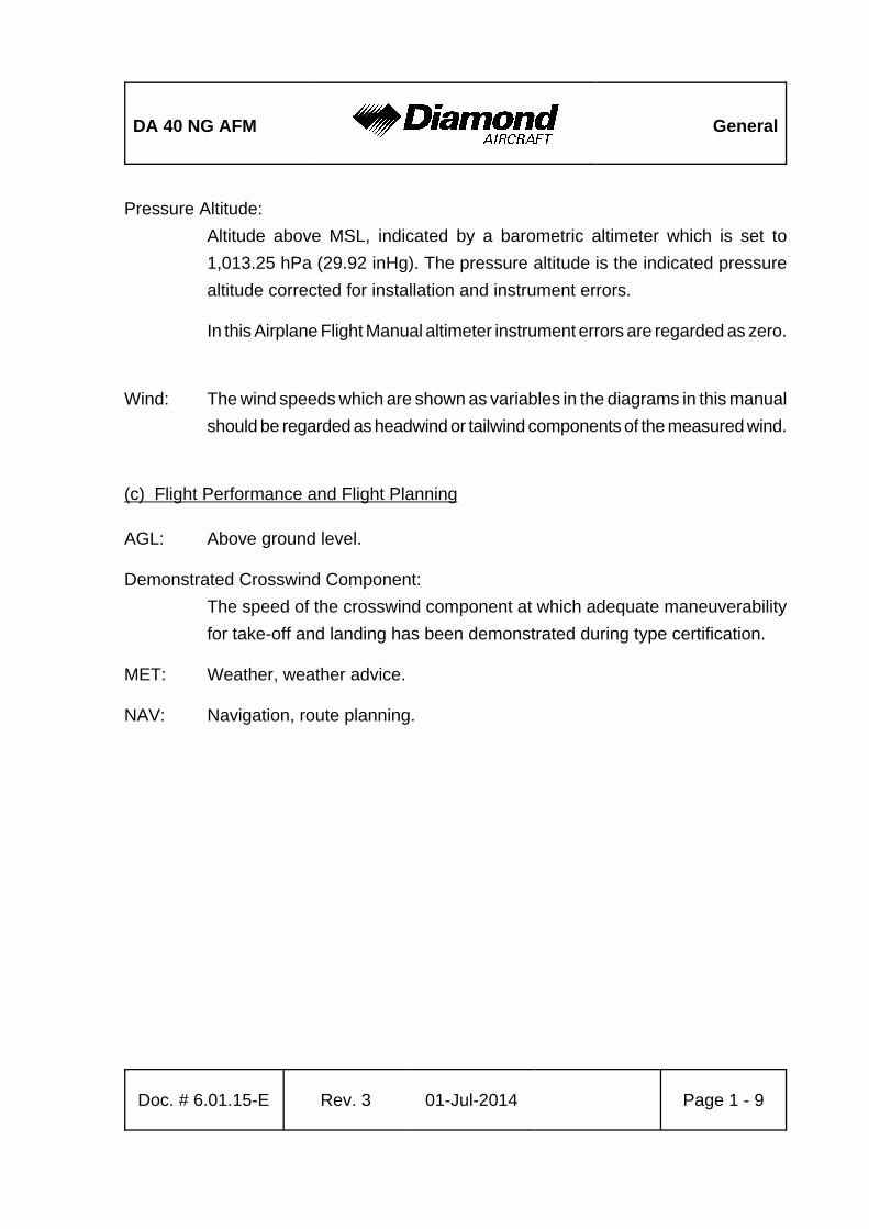
Pressure Altitude:
Altitude above MSL, indicated by a barometric altimeter which is set to
1,013.25 hPa (29.92 inHg). The pressure altitude is the indicated pressure
altitude corrected for installation and instrument errors.
In this Airplane Flight Manual altimeter instrument errors are regarded as zero.
Wind: The wind speeds which are shown as variables in the diagrams in this manual
should be regarded as headwind or tailwind components of the measured wind.
(c) Flight Performance and Flight Planning
AGL: Above ground level.
Demonstrated Crosswind Component:
The speed of the crosswind component at which adequate maneuverability
for take-off and landing has been demonstrated during type certification.
MET: Weather, weather advice.
NAV: Navigation, route planning.
General DA 40 NG AFM
Page 1 - 10 Rev. 3 01-Jul-2014 Doc. # 6.01.15-E
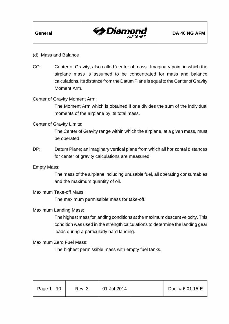
(d) Mass and Balance
CG: Center of Gravity, also called 'center of mass'. Imaginary point in which the
airplane mass is assumed to be concentrated for mass and balance
calculations. Its distance from the Datum Plane is equal to the Center of Gravity
Moment Arm.
Center of Gravity Moment Arm:
The Moment Arm which is obtained if one divides the sum of the individual
moments of the airplane by its total mass.
Center of Gravity Limits:
The Center of Gravity range within which the airplane, at a given mass, must
be operated.
DP: Datum Plane; an imaginary vertical plane from which all horizontal distances
for center of gravity calculations are measured.
Empty Mass:
The mass of the airplane including unusable fuel, all operating consumables
and the maximum quantity of oil.
Maximum Take-off Mass:
The maximum permissible mass for take-off.
Maximum Landing Mass:
The highest mass for landing conditions at the maximum descent velocity. This
condition was used in the strength calculations to determine the landing gear
loads during a particularly hard landing.
Maximum Zero Fuel Mass:
The highest permissible mass with empty fuel tanks.
DA 40 NG AFM General
Doc. # 6.01.15-E Rev. 3 01-Jul-2014 Page 1 - 11
Moment Arm:
The horizontal distance from the Datum Plane to the Center of Gravity of a
component.
Moment: The mass of a component multiplied by its moment arm.
Usable Fuel:
The quantity of fuel available for flight planning.
Unusable Fuel:
The quantity of fuel remaining in the tank which cannot be used for flight.
Useful Load:
The difference between take-off mass and empty mass.
(e) Engine
CT: Coolant Temperature.
EECU: Electronic Engine Control Unit.
GT: Gearbox Temperature.
LOAD: Engine output power in percent of take-off power.
MED: Main Engine Display.
OP: Oil Pressure (oil pressure in the lubrication system of the engine).
OT: Oil Temperature (oil temperature in the lubrication system of the engine).
RPM: Revolutions per minute (rotational speed of the propeller).
SED: Secondary Engine Display.
FT: Fuel Temperature.
General DA 40 NG AFM
Page 1 - 12 Rev. 3 01-Jul-2014 Doc. # 6.01.15-E
(f) Designation of the Circuit Breakers on the Instrument Panel
ADC: Air Data Computer.
ADF: Automatic Direction Finder.
AHRS: Attitude and Heading Reference System.
ANNUN: Annunciator Panel.
AV/CDU FAN:
Avionic-, CDU-Cooling Fans.
AV. BUS: Avionic Bus.
AUDIO: Audio Panel / Marker Beacon Receiver.
AUTOPILOT:
Autopilot System.
COM: COM Radio.
COM1: COM Radio No. 1.
COM2: COM Radio No. 2.
DG: Directional Gyro.
DME: Distance Measuring Equipment.
EECU A: ECU A.
EECU B: ECU B.
ENG INST: Engine Instruments.
ESS TIE: Bus Interconnection.
FAN/OAT: Fan / Outside Air Temperature.
FLAPS: Flap System.
FLOOD: Flood Light.
FUEL PUMP A:
ECU A Fuel Pump.
FUEL PUMP B:
ECU B Fuel Pump.
GPS: Global Positioning System.
GPS/NAV1: Global Positioning System and NAV Receiver No. 1.
GPS/NAV2: Global Positioning System and NAV Receiver No. 2.
HORIZON: Artificial Horizon (Attitude Gyro).
DA 40 NG AFM General
Doc. # 6.01.15-E Rev. 3 01-Jul-2014 Page 1 - 13
INST.1: Engine Instrument.
INST. LT: Instrument Lights.
LANDING: Landing Light.
MAIN TIE: Bus Interconnection.
MASTER CONTROL:
Master Control (Avionics Relay).
MFD: Multi Function Display.
NAV: NAV Receiver.
PFD: Primary Flight Display.
PITOT: Pitot Heating System.
POSITION: Position Lights.
PWR: Power.
START: Starter.
STROBE: Strobe Lights (= Anti Collision Lights).
T & B: Turn and Bank Indicator.
TAS: Traffic Advisory System.
TAXI/MAP: Taxi Light / Map Lights.
WX500: Stormscope.
XFR PUMP: Fuel Transfer Pump.
XPDR Transponder.
(g) Equipment
ELT: Emergency Locator Transmitter.
(h) Design Change Advisories
MÄM: Mandatory Design Change Advisory.
OÄM: Optional Design Change Advisory.
General DA 40 NG AFM
Page 1 - 14 Rev. 3 01-Jul-2014 Doc. # 6.01.15-E
(i) Miscellaneous
ACG: Austro Control GmbH (formerly BAZ, Federal Office of Civil Aviation).
ATC: Air Traffic Control.
CFRP: Carbon Fiber Reinforced Plastic.
EASA: European Aviation Safety Agency.
GFRP: Glass Fiber Reinforced Plastic.
GIA: Garmin Integrated Avionics.
JAR: Joint Aviation Requirements.
DA 40 NG AFM General
Doc. # 6.01.15-E Rev. 3 01-Jul-2014 Page 1 - 15
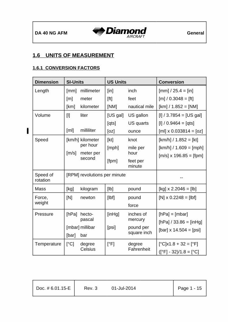
1.6 UNITS OF MEASUREMENT
1.6.1 CONVERSION FACTORS
Dimension SI-Units US Units Conversion
Length [mm] millimeter
[m] meter
[km] kilometer
[in] inch
[ft] feet
[NM] nautical mile
[mm] / 25.4 = [in]
[m] / 0.3048 = [ft]
[km] / 1.852 = [NM]
Volume [l] liter
[ml] milliliter%
[US gal] US gallon
[qts] US quarts
[oz] ounce%
[l] / 3.7854 = [US gal]
[l] / 0.9464 = [qts]
[ml] x 0.033814 = [oz]%
Speed [km/h] kilometerper hour
[m/s] meter persecond
[kt] knot
[mph] mile perhour
[fpm] feet perminute
[km/h] / 1.852 = [kt]
[km/h] / 1.609 = [mph]
[m/s] x 196.85 = [fpm]
Speed ofrotation
[RPM] revolutions per minute--
Mass [kg] kilogram [lb] pound [kg] x 2.2046 = [lb]
Force,weight
[N] newton [lbf] pound
force
[N] x 0.2248 = [lbf]
Pressure [hPa] hecto-pascal
[mbar] millibar
[bar] bar
[inHg] inches ofmercury
[psi] pound persquare inch
[hPa] = [mbar]
[hPa] / 33.86 = [inHg]
[bar] x 14.504 = [psi]
Temperature [°C] degreeCelsius
[°F] degreeFahrenheit
[°C]x1.8 + 32 = [°F]
([°F] - 32)/1.8 = [°C]
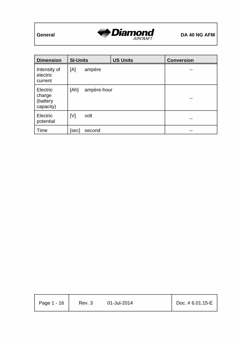
General DA 40 NG AFM
Dimension SI-Units US Units Conversion
Page 1 - 16 Rev. 3 01-Jul-2014 Doc. # 6.01.15-E
Intensity ofelectriccurrent
[A] ampère --
Electriccharge(batterycapacity)
[Ah] ampère-hour
--
Electricpotential
[V] volt--
Time [sec] second --
DA 40 NG AFM General
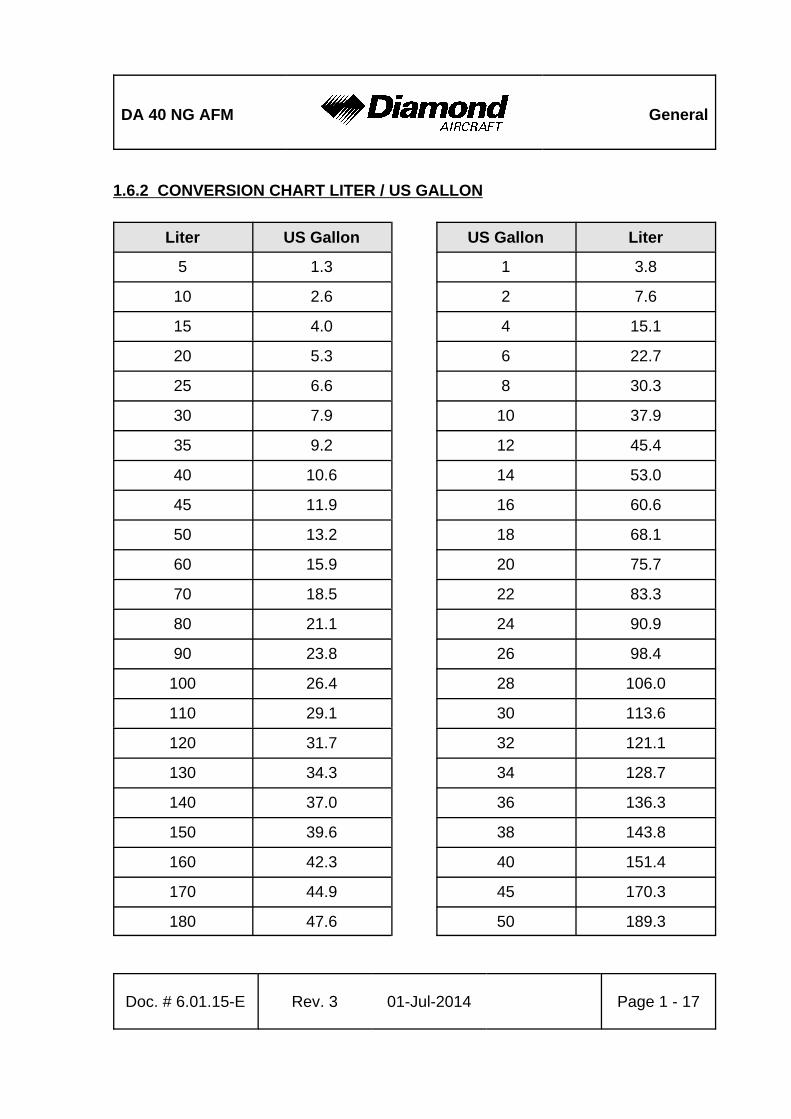
Doc. # 6.01.15-E Rev. 3 01-Jul-2014 Page 1 - 17
1.6.2 CONVERSION CHART LITER / US GALLON
Liter US Gallon US Gallon Liter
5 1.3 1 3.8
10 2.6 2 7.6
15 4.0 4 15.1
20 5.3 6 22.7
25 6.6 8 30.3
30 7.9 10 37.9
35 9.2 12 45.4
40 10.6 14 53.0
45 11.9 16 60.6
50 13.2 18 68.1
60 15.9 20 75.7
70 18.5 22 83.3
80 21.1 24 90.9
90 23.8 26 98.4
100 26.4 28 106.0
110 29.1 30 113.6
120 31.7 32 121.1
130 34.3 34 128.7
140 37.0 36 136.3
150 39.6 38 143.8
160 42.3 40 151.4
170 44.9 45 170.3
180 47.6 50 189.3
General DA 40 NG AFM
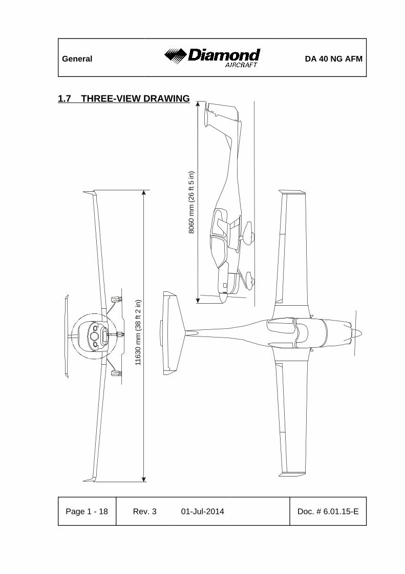
Page 1 - 18 Rev. 3 01-Jul-2014 Doc. # 6.01.15-E
8060
mm
(26
ft 5
in)
1163
0 m
m (
38 ft 2
in)
1.7 THREE-VIEW DRAWING
DA 40 NG AFM General
Doc. # 6.01.15-E Rev. 3 01-Jul-2014 Page 1 - 19
1.8 SOURCE DOCUMENTATION
This section lists documents, manuals and other literature that were used as sources for
the Airplane Flight Manual, and indicates the respective publisher. However, only the
information given in the Airplane Flight Manual is valid.
1.8.1 ENGINE AND ENGINE INSTRUMENTS
Address: Austro Engine GmbH
Rudolf Diesel-Str. 11
A-2700 Wiener Neustadt
AUSTRIA
Phone: +43-2622-23 000
Fax: +43-2622-23 000 - 2711
Internet: www.austroengine.at
Documents: Operation Manual AE300,
E4.01.01
Maintenance Manual AE300,
E4.08.04
Installation Manual AE300,
E4.02.01
General DA 40 NG AFM
Page 1 - 20 Rev. 3 01-Jul-2014 Doc. # 6.01.15-E
1.8.2 PROPELLER
Address: mt-propeller
Airport Straubing Wallmühle
D-94348 ATTING
GERMANY
Phone: +49-9429-9409-0
E-mail: [email protected]
Internet: www.mt-propeller.de
Documents: E-124, Operation and Installation Manual
Hydraulically controlled variable pitch propeller
MTV -5, -6, -9, -11, -12, -14, -15, -16, -21, -22, -25
DA 40 NG AFMOperating
Limitations
Doc. # 6.01.15-E Rev. 3 01-Jul-2014EASA
approvedPage 2 - 1
CHAPTER 2
OPERATING LIMITATIONS
Page
2.1 INTRODUCTION . . . . . . . . . . . . . . . . . . . . . . . . . . . . . . . . . . . . . . . 2-2
2.2 AIRSPEED . . . . . . . . . . . . . . . . . . . . . . . . . . . . . . . . . . . . . . . . . . . 2-3
2.3 AIRSPEED INDICATOR MARKINGS . . . . . . . . . . . . . . . . . . . . . . . 2-4
2.4 POWER-PLANT LIMITATIONS . . . . . . . . . . . . . . . . . . . . . . . . . . . 2-5
2.5 ENGINE INSTRUMENT MARKINGS . . . . . . . . . . . . . . . . . . . . . . 2-11
2.6 WARNING, CAUTION AND STATUS LIGHTS . . . . . . . . . . . . . . . 2-12
2.7 MASS (WEIGHT) . . . . . . . . . . . . . . . . . . . . . . . . . . . . . . . . . . . . . 2-16
2.8 CENTER OF GRAVITY . . . . . . . . . . . . . . . . . . . . . . . . . . . . . . . . . 2-18
2.9 APPROVED MANEUVERS . . . . . . . . . . . . . . . . . . . . . . . . . . . . . . 2-19
2.10 MANEUVERING LOAD FACTORS . . . . . . . . . . . . . . . . . . . . . . . . 2-20
2.11 OPERATING ALTITUDE . . . . . . . . . . . . . . . . . . . . . . . . . . . . . . . . 2-21
2.12 FLIGHT CREW . . . . . . . . . . . . . . . . . . . . . . . . . . . . . . . . . . . . . . . 2-21
2.13 KINDS OF OPERATION . . . . . . . . . . . . . . . . . . . . . . . . . . . . . . . . 2-22
2.14 FUEL . . . . . . . . . . . . . . . . . . . . . . . . . . . . . . . . . . . . . . . . . . . . . . . 2-26
2.15 LIMITATION PLACARDS . . . . . . . . . . . . . . . . . . . . . . . . . . . . . . . 2-29
2.16 OTHER LIMITATIONS . . . . . . . . . . . . . . . . . . . . . . . . . . . . . . . . . 2-35
2.16.1 TEMPERATURE . . . . . . . . . . . . . . . . . . . . . . . . . . . . . . . . 2-35
2.16.2 BATTERY CHARGE . . . . . . . . . . . . . . . . . . . . . . . . . . . . . 2-35
2.16.3 EMERGENCY SWITCH . . . . . . . . . . . . . . . . . . . . . . . . . . 2-35
. . . . . . . . . . . . . . . . . . . . . . . . . . . . . . . . . . . . . . . . . . . . . . . . . . . 2-35
2.16.4 DOOR LOCKING DEVICE . . . . . . . . . . . . . . . . . . . . . . . . 2-36
2.16.5 ELECTRONIC EQUIPMENT . . . . . . . . . . . . . . . . . . . . . . . 2-36
2.16.6 SMOKING . . . . . . . . . . . . . . . . . . . . . . . . . . . . . . . . . . . . . 2-36
2.16.7 USE OF THE SUN VISORS . . . . . . . . . . . . . . . . . . . . . . . 2-36
Operating
LimitationsDA 40 NG AFM
Page 2 - 2 Rev. 3 01-Jul-2014EASA
approvedDoc. # 6.01.15-E
2.1 INTRODUCTION
Chapter 2 of this Airplane Flight Manual includes operating limitations, instrument
markings, and placards necessary for the safe operation of the airplane, its power-plant,
standard systems and standard equipment.
The limitations included in this Chapter are approved.
WARNING
Operation of the airplane outside of the approved operating
limitations is not permissible.
DA 40 NG AFMOperating
Limitations
Doc. # 6.01.15-E Rev. 3 01-Jul-2014EASA
approvedPage 2 - 3
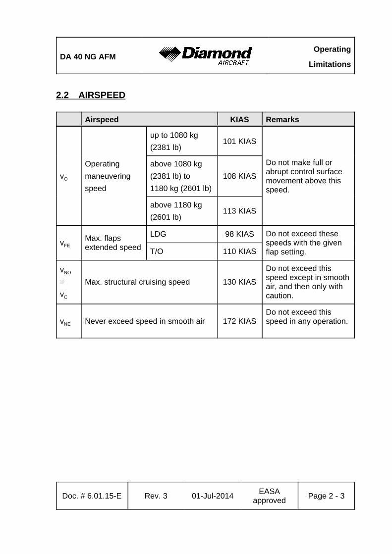
2.2 AIRSPEED
Airspeed KIAS Remarks
vO
Operating
maneuvering
speed
up to 1080 kg
(2381 lb)101 KIAS
Do not make full orabrupt control surfacemovement above thisspeed.
above 1080 kg
(2381 lb) to
1180 kg (2601 lb)
108 KIAS
above 1180 kg
(2601 lb)113 KIAS
vFEMax. flapsextended speed
LDG 98 KIAS Do not exceed thesespeeds with the givenflap setting.T/O 110 KIAS
vNO
=
vC
Max. structural cruising speed 130 KIAS
Do not exceed thisspeed except in smoothair, and then only withcaution.
vNE Never exceed speed in smooth air 172 KIASDo not exceed thisspeed in any operation.
Operating
LimitationsDA 40 NG AFM
Page 2 - 4 Rev. 3 01-Jul-2014EASA
approvedDoc. # 6.01.15-E
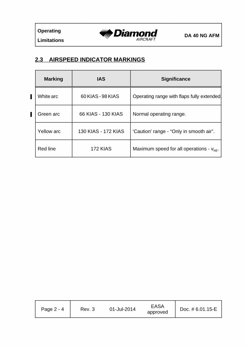
2.3 AIRSPEED INDICATOR MARKINGS
Marking IAS Significance
White arc' 60 KIAS - 98 KIAS' Operating range with flaps fully extended.
Green arc' 66 KIAS - 130 KIAS' Normal operating range.
Yellow arc 130 KIAS - 172 KIAS 'Caution' range - “Only in smooth air”.
Red line 172 KIAS Maximum speed for all operations - vNE.
DA 40 NG AFMOperating
Limitations
Doc. # 6.01.15-E Rev. 3 01-Jul-2014EASA
approvedPage 2 - 5
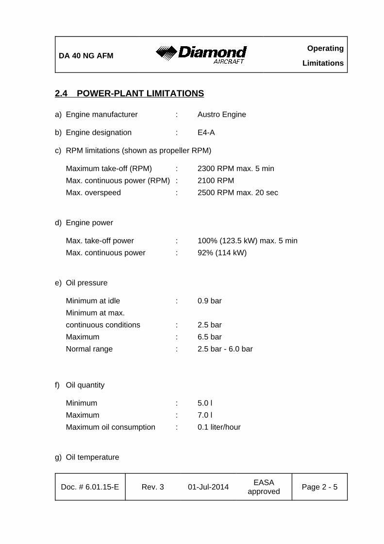
2.4 POWER-PLANT LIMITATIONS
a) Engine manufacturer : Austro Engine
b) Engine designation : E4-A
c) RPM limitations (shown as propeller RPM)
Maximum take-off (RPM) : 2300 RPM max. 5 min
Max. continuous power (RPM) : 2100 RPM
Max. overspeed : 2500 RPM max. 20 sec
d) Engine power
Max. take-off power : 100% (123.5 kW) max. 5 min
Max. continuous power : 92% (114 kW)
e) Oil pressure
Minimum at idle : 0.9 bar
Minimum at max.
continuous conditions : 2.5 bar
Maximum : 6.5 bar
Normal range : 2.5 bar - 6.0 bar
f) Oil quantity
Minimum : 5.0 l
Maximum : 7.0 l
Maximum oil consumption : 0.1 liter/hour
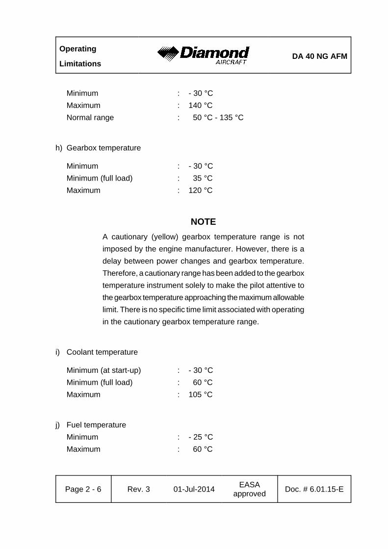
g) Oil temperature
Operating
LimitationsDA 40 NG AFM
Page 2 - 6 Rev. 3 01-Jul-2014EASA
approvedDoc. # 6.01.15-E
Minimum : - 30 °C
Maximum : 140 °C
Normal range : 50 °C - 135 °C
h) Gearbox temperature
Minimum : - 30 °C
Minimum (full load) : 35 °C
Maximum : 120 °C
NOTE
A cautionary (yellow) gearbox temperature range is not
imposed by the engine manufacturer. However, there is a
delay between power changes and gearbox temperature.
Therefore, a cautionary range has been added to the gearbox
temperature instrument solely to make the pilot attentive to
the gearbox temperature approaching the maximum allowable
limit. There is no specific time limit associated with operating
in the cautionary gearbox temperature range.
i) Coolant temperature
Minimum (at start-up) : - 30 °C
Minimum (full load) : 60 °C
Maximum : 105 °C
j) Fuel temperature
Minimum : - 25 °C
Maximum : 60 °C
DA 40 NG AFMOperating
Limitations
Doc. # 6.01.15-E Rev. 3 01-Jul-2014EASA
approvedPage 2 - 7
k) Fuel pressure (absolute pressure)
Minimum : 4 bar
NOTE
The fuel pressure is not indicated; a fuel pressure warning
will illuminate on the PFD (if G1000 is installed) or SED (if
installed) if the pressure is below the limit.
Maximum : 7 bar
NOTE
The fuel pressure is not indicated; the fuel pressure caution
ECU A/B FAIL on the PFD (if G1000 is installed) or ECU A/B
on the White Wire annunciator panel (if installed) will
illuminate if the pressure is above the limit.
l) Voltage
Minimum : 24.1 V
Maximum : 32.0 V
m) Amperage
Maximum : 70 A
n) Propeller manufacturer : mt-Propeller
o) Propeller designation : MTV-6-R/190-69
p) Propeller diameter : 190 cm (6 ft 3 in)
q) Prop. pitch angle (@ 0.75 R) : Low Pitch 14.5E± 0.2E
High Pitch 35E± 1.0E
Operating
LimitationsDA 40 NG AFM
Page 2 - 8 Rev. 3 01-Jul-2014EASA
approvedDoc. # 6.01.15-E
r) Governor : mt-Propeller P-853-16 electrical governor
s) Oil specification :
Approved Engine Oil Types' SAE Grade'
SHELL HELIX ULTRA ' 5W-30'
ADDINOL SUPER POWER MV 0537' 5W-30'
BP Visco 5000 5W-30' 5W-30'
REPSOL ELITE Common Rail 5W30' 5W-30'
Gulf Formula GMX' 5W-30'
G-Energy F Synth 5W-30' 5W-30'
QUARTZ 9000 ENERGY 5W-30' 5W-30'
Gulf Formula GX' 5W-30'
AEROSHELL Oil Diesel Ultra' 5W-30'
CASTROL Edge 5W-30 A3' 5W-30'
CASTROL Edge Professional A3' 5W-30'
SHELL HELIX ULTRA' 5W-40'
LIQUI MOLY 5W-40 LEICHTLAUF HIGH TECH' 5W-40'
megol Motorenoel High Condition' 5W-40'
PETRONAS Syntium 3000' 5W-40'
LUKOIL LUXE synthetic' 5W-40'
CASTROL Edge Professional A3' 5W-40'
CASTROL Magnatec Professional A3' 5W-40'
VALVOLINE SynPower HST' 5W-40'
VALVOLINE SynPower' 5W-40'
GULF Formula GX' 5W-40'
Castrol SLX Professional Longtec 0W-40' 0W-40'
DA 40 NG AFMOperating
Limitations
Doc. # 6.01.15-E Rev. 3 01-Jul-2014EASA
approvedPage 2 - 9
CASTROL Edge 0W-40 A3/B4 ' 0W-40'
CASTROL Edge Professional A3' 0W-40'
SHELL HELIX Ultra' 0W-40'
'
CAUTION'
Only engine oils conforming to MB 229.5 specification are'
approved by Austro Engine GmbH to be used for operation.'
'
NOTE'
It is not recommended to mix different SAE grades.'
t) Gearbox oil (propeller gearbox) : SHELL SPIRAX GSX 75W-80
SHELL SPIRAX S6 GXME 75W-80'
u) Coolant : Distilled water / Cooler protection (BASF
Glysantin Protect Plus / G48):
- Mixture ratio 50% / 50% for freezing point'
-38°C (-36°F).'
- Mixture ratio 40% / 60% (MÄM 40-638 is'
carried out) freezing point -53 °C (-63°F) '
CAUTION
If the coolant or gearbox oil level is low the reason must
be determined and the problem must be corrected by
authorized personnel.
Operating
LimitationsDA 40 NG AFM
Page 2 - 10 Rev. 3 01-Jul-2014EASA
approvedDoc. # 6.01.15-E
v) Maximum restart altitude : 16,400 ft pressure altitude
for immediate restarts
10,000 ft pressure altitude
for restarts within 2 minutes

DA 40 NG AFMOperating
Limitations
Doc. # 6.01.15-E Rev. 3 01-Jul-2014EASA
approvedPage 2 - 11
2.5 ENGINE INSTRUMENT MARKINGS
Engine instrument markings and their color code significance are shown in the table
below:
Indi-cation
Redarc/bar
=lower
prohibitedrange
Yellowarc/bar
=cautionrange
Greenarc/bar
=normal
operatingrange
Yellowarc/bar
=cautionrange
Redarc/bar
=upper
prohibitedrange
RPM -- --up to
2100 RPM
2100 to
2300 RPM
above
2300 RPM
Oilpressure
below
0.9 bar0.9 to 2.5 bar 2.5 to 6.0 bar 6.0 to 6.5 bar above 6.5 bar
Oiltemp.
below -30°C -30° to 50°C 50° to 135°C 135° to140°C above 140°C
Coolanttemp.
below -30°C -30° to 60°C 60° to 95°C 95° to 105°C above 105°C
Gearboxtemp.
below -30°C -30° to 35°C 35° to 115°C 115° to 120°C above 120°C
Load -- -- up to 92% 92 - 100% --
Fueltemp.
below -25°C -25° to -20°C -20° to 55°C 55° to 60°C above 60°C
Ammeter -- -- up to 60A 60 to 70A above 70A
Volt-meter
below 24.1V 24.1 to 25V 25 to 30V 30 to 32V above 32V
Fuel qty. below
1 US gal--
1 to 14
US gal-- --
Operating
LimitationsDA 40 NG AFM
Page 2 - 12 Rev. 3 01-Jul-2014EASA
approvedDoc. # 6.01.15-E
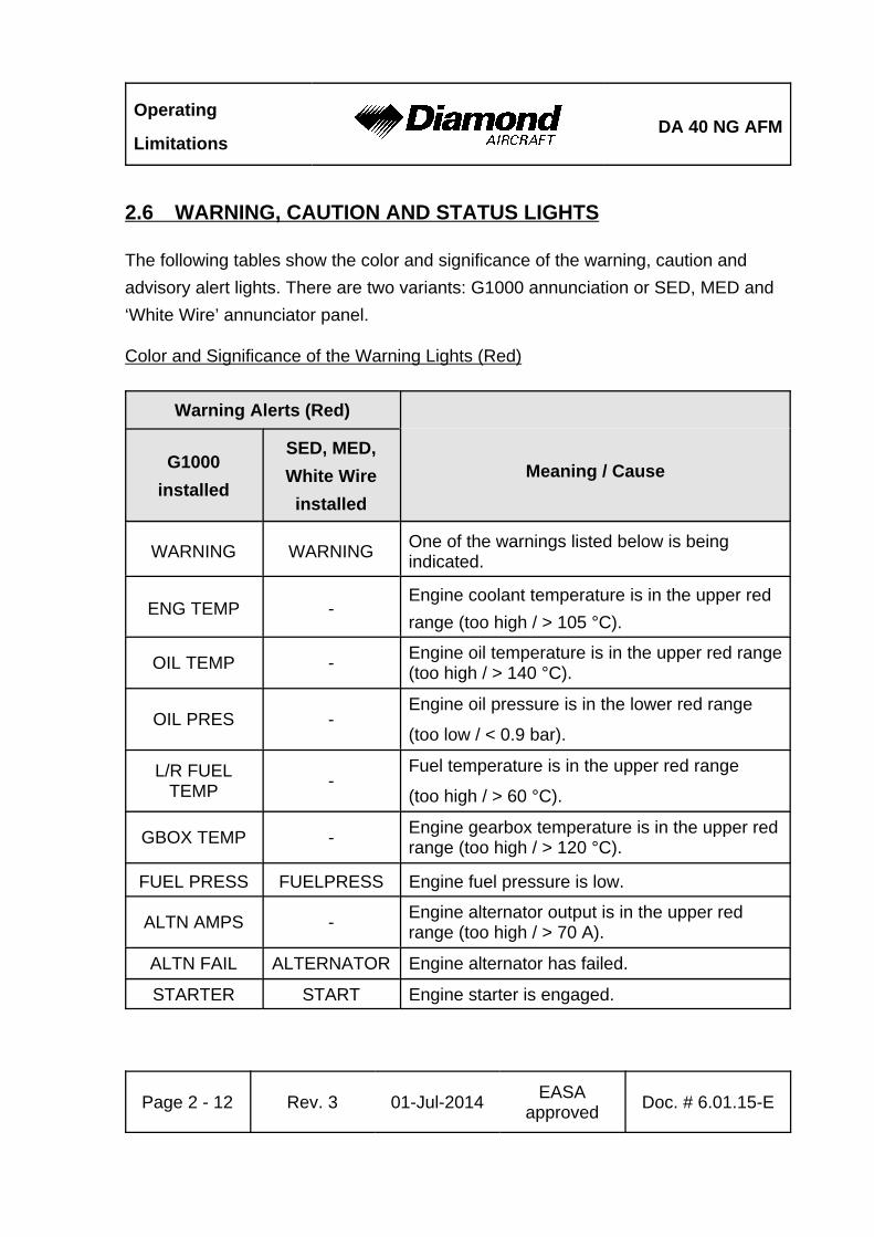
2.6 WARNING, CAUTION AND STATUS LIGHTS
The following tables show the color and significance of the warning, caution and
advisory alert lights. There are two variants: G1000 annunciation or SED, MED and
‘White Wire’ annunciator panel.
Color and Significance of the Warning Lights (Red)
Warning Alerts (Red)
Meaning / CauseG1000
installed
SED, MED,
White Wire
installed
WARNING WARNINGOne of the warnings listed below is beingindicated.
ENG TEMP -Engine coolant temperature is in the upper red
range (too high / > 105 °C).
OIL TEMP -Engine oil temperature is in the upper red range(too high / > 140 °C).
OIL PRES -Engine oil pressure is in the lower red range
(too low / < 0.9 bar).
L/R FUELTEMP
-Fuel temperature is in the upper red range
(too high / > 60 °C).
GBOX TEMP -Engine gearbox temperature is in the upper redrange (too high / > 120 °C).
FUEL PRESS FUELPRESS Engine fuel pressure is low.
ALTN AMPS -Engine alternator output is in the upper redrange (too high / > 70 A).
ALTN FAIL ALTERNATOR Engine alternator has failed.
STARTER START Engine starter is engaged.
DA 40 NG AFMOperating
Limitations
Warning Alerts (Red)
Meaning / CauseG1000
installed
SED, MED,
White Wire
installed
Doc. # 6.01.15-E Rev. 3 01-Jul-2014EASA
approvedPage 2 - 13
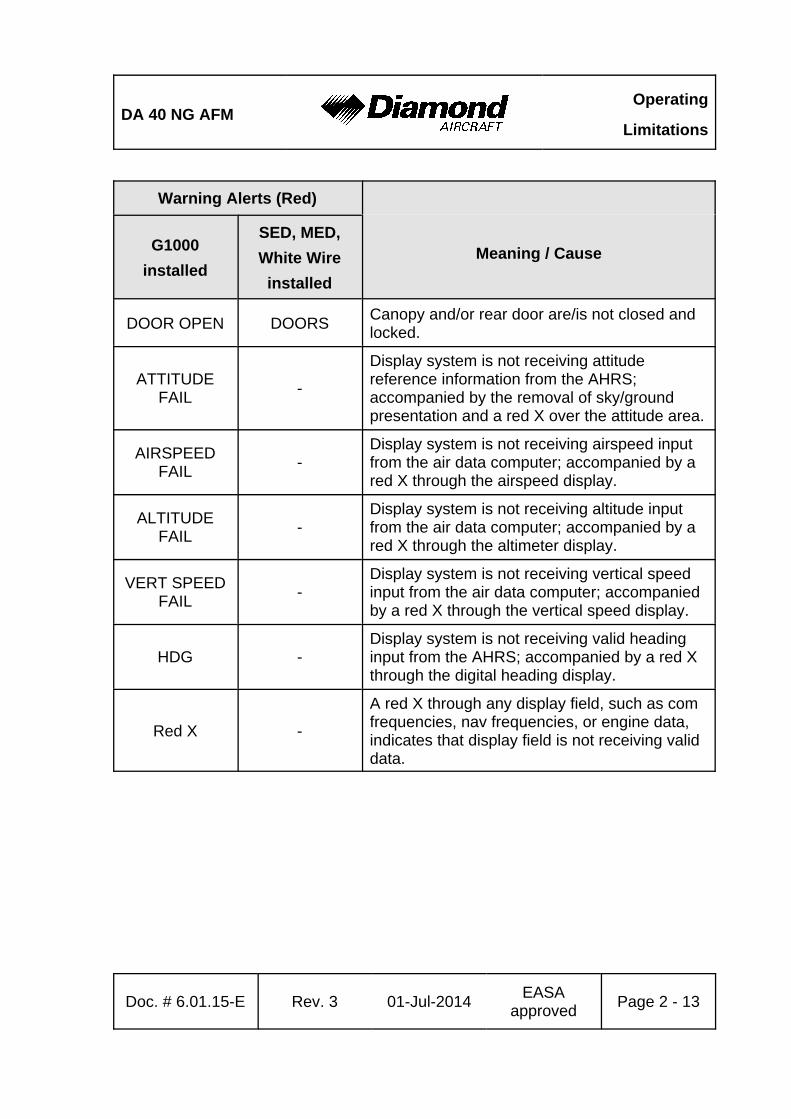
DOOR OPEN DOORSCanopy and/or rear door are/is not closed andlocked.
ATTITUDEFAIL
-
Display system is not receiving attitudereference information from the AHRS;accompanied by the removal of sky/groundpresentation and a red X over the attitude area.
AIRSPEEDFAIL
-Display system is not receiving airspeed inputfrom the air data computer; accompanied by ared X through the airspeed display.
ALTITUDEFAIL
-Display system is not receiving altitude inputfrom the air data computer; accompanied by ared X through the altimeter display.
VERT SPEEDFAIL
-Display system is not receiving vertical speedinput from the air data computer; accompaniedby a red X through the vertical speed display.
HDG -Display system is not receiving valid headinginput from the AHRS; accompanied by a red Xthrough the digital heading display.
Red X -
A red X through any display field, such as comfrequencies, nav frequencies, or engine data,indicates that display field is not receiving validdata.
Operating
LimitationsDA 40 NG AFM
Page 2 - 14 Rev. 3 01-Jul-2014EASA
approvedDoc. # 6.01.15-E
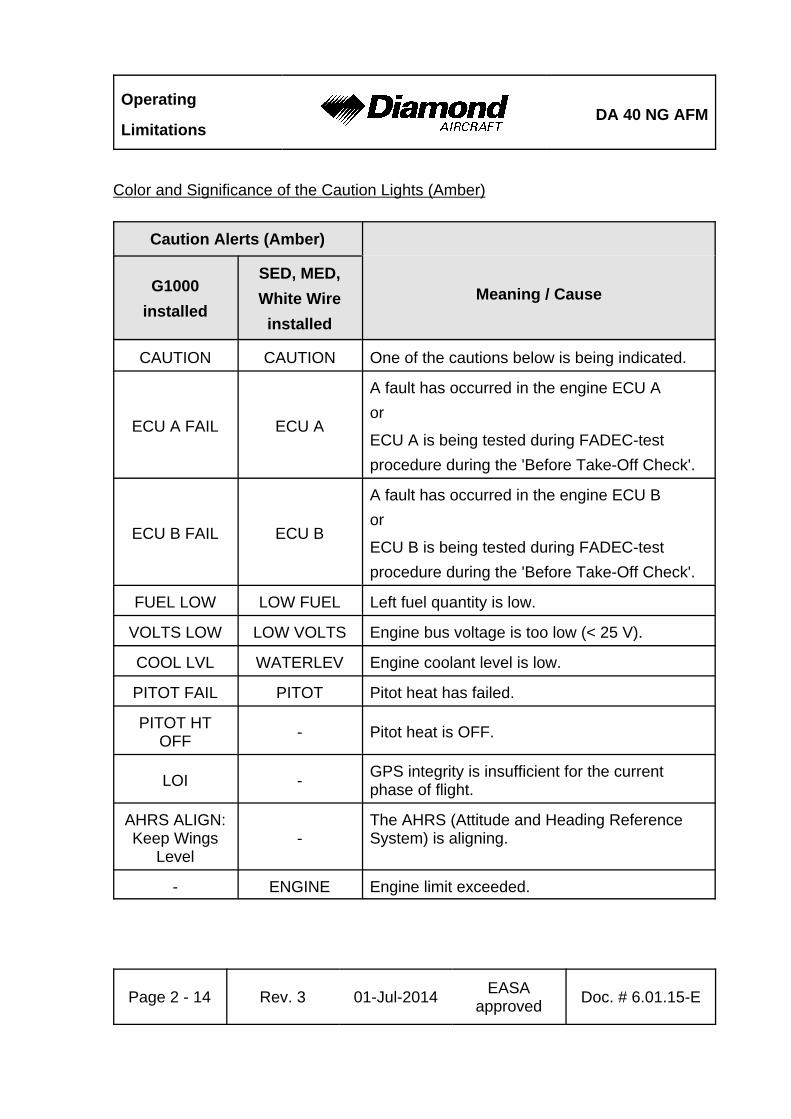
Color and Significance of the Caution Lights (Amber)
Caution Alerts (Amber)
Meaning / CauseG1000
installed
SED, MED,
White Wire
installed
CAUTION CAUTION One of the cautions below is being indicated.
ECU A FAIL ECU A
A fault has occurred in the engine ECU A
or
ECU A is being tested during FADEC-test
procedure during the 'Before Take-Off Check'.
ECU B FAIL ECU B
A fault has occurred in the engine ECU B
or
ECU B is being tested during FADEC-test
procedure during the 'Before Take-Off Check'.
FUEL LOW LOW FUEL Left fuel quantity is low.
VOLTS LOW LOW VOLTS Engine bus voltage is too low (< 25 V).
COOL LVL WATERLEV Engine coolant level is low.
PITOT FAIL PITOT Pitot heat has failed.
PITOT HTOFF
- Pitot heat is OFF.
LOI -GPS integrity is insufficient for the currentphase of flight.
AHRS ALIGN:Keep Wings
Level-
The AHRS (Attitude and Heading ReferenceSystem) is aligning.
- ENGINE Engine limit exceeded.
DA 40 NG AFMOperating
Limitations
Doc. # 6.01.15-E Rev. 3 01-Jul-2014EASA
approvedPage 2 - 15
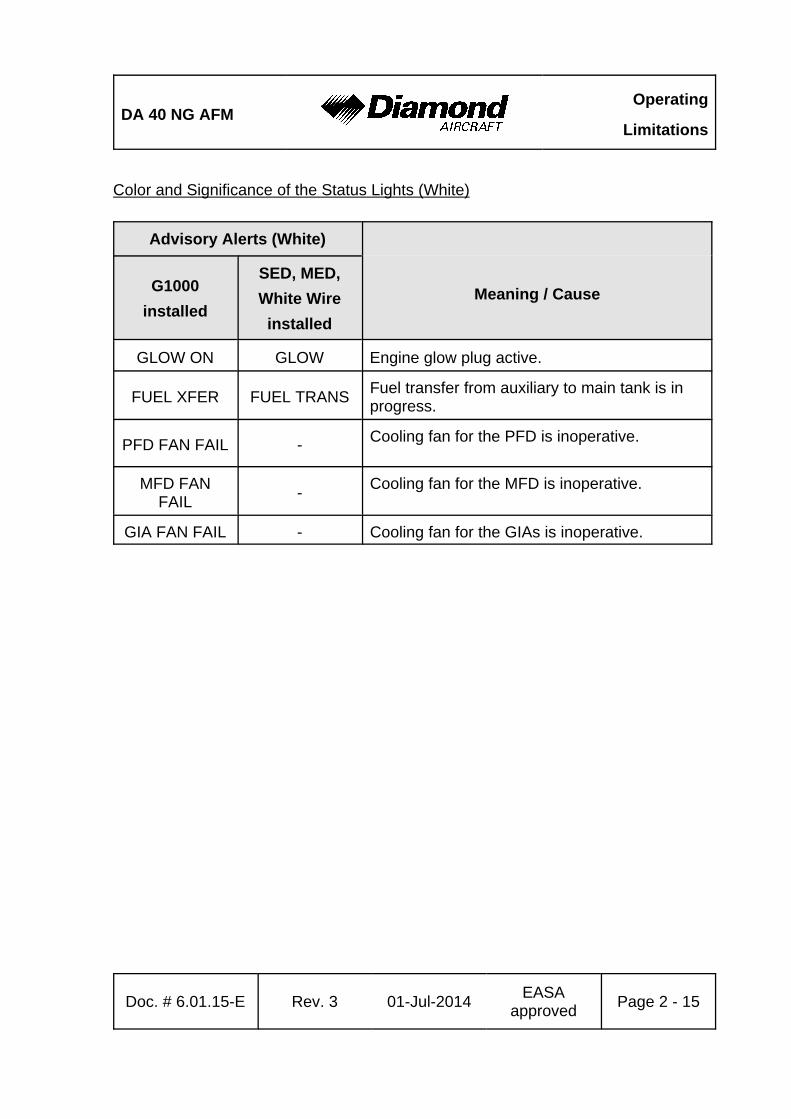
Color and Significance of the Status Lights (White)
Advisory Alerts (White)
Meaning / CauseG1000
installed
SED, MED,
White Wire
installed
GLOW ON GLOW Engine glow plug active.
FUEL XFER FUEL TRANSFuel transfer from auxiliary to main tank is inprogress.
PFD FAN FAIL - Cooling fan for the PFD is inoperative.
MFD FANFAIL
-Cooling fan for the MFD is inoperative.
GIA FAN FAIL - Cooling fan for the GIAs is inoperative.
Operating
LimitationsDA 40 NG AFM
Page 2 - 16 Rev. 3 01-Jul-2014EASA
approvedDoc. # 6.01.15-E
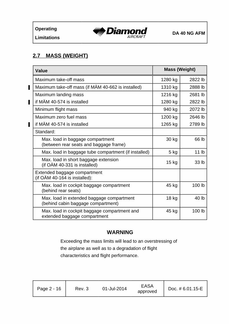
2.7 MASS (WEIGHT)
Value Mass (Weight)
Maximum take-off mass 1280 kg 2822 lb
Maximum take-off mass (if MÄM 40-662 is installed)' 1310 kg' 2888 lb'
Maximum landing mass
if MÄM 40-574 is installed'
1216 kg
1280 kg'
2681 lb
2822 lb'
Minimum flight mass 940 kg 2072 lb
Maximum zero fuel mass
if MÄM 40-574 is installed'
1200 kg
1265 kg'
2646 lb
2789 lb'
Standard:
Max. load in baggage compartment(between rear seats and baggage frame)
30 kg 66 lb
Max. load in baggage tube compartment (if installed) 5 kg 11 lb
Max. load in short baggage extension(if OÄM 40-331 is installed)
15 kg 33 lb
Extended baggage compartment (if OÄM 40-164 is installed):
Max. load in cockpit baggage compartment(behind rear seats)
45 kg 100 lb
Max. load in extended baggage compartment(behind cabin baggage compartment)
18 kg 40 lb
Max. load in cockpit baggage compartment and extended baggage compartment
45 kg 100 lb
WARNING
Exceeding the mass limits will lead to an overstressing of
the airplane as well as to a degradation of flight
characteristics and flight performance.
DA 40 NG AFMOperating
Limitations
Doc. # 6.01.15-E Rev. 3 01-Jul-2014EASA
approvedPage 2 - 17
NOTE
In some countries the beginning of a flight is defined by
starting the engine. In those countries a maximum ramp mass
4 kg (9 lb) above the maximum take-off mass is approved.
At the time of lift-off the maximum permitted take-off mass
must not be exceeded.
NOTE
The maximum zero fuel mass is the highest mass with empty
fuel tanks.
Operating
LimitationsDA 40 NG AFM
Page 2 - 18 Rev. 3 01-Jul-2014EASA
approvedDoc. # 6.01.15-E
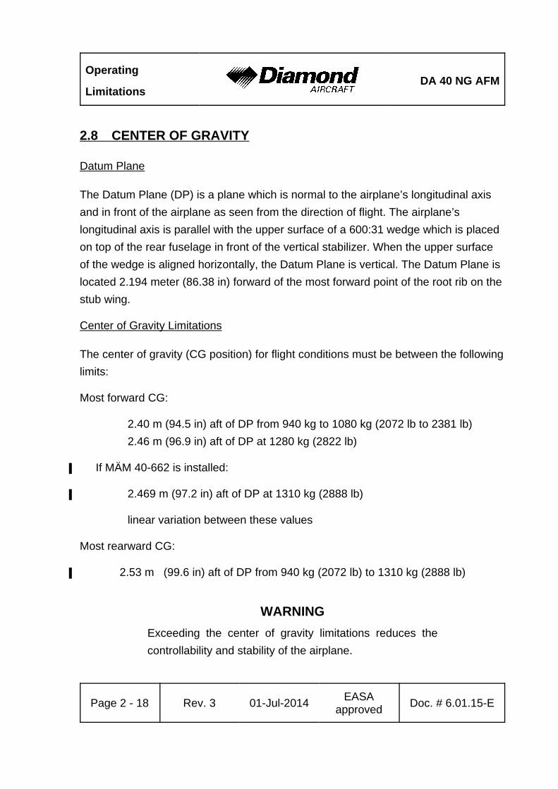
2.8 CENTER OF GRAVITY
Datum Plane
The Datum Plane (DP) is a plane which is normal to the airplane’s longitudinal axis
and in front of the airplane as seen from the direction of flight. The airplane’s
longitudinal axis is parallel with the upper surface of a 600:31 wedge which is placed
on top of the rear fuselage in front of the vertical stabilizer. When the upper surface
of the wedge is aligned horizontally, the Datum Plane is vertical. The Datum Plane is
located 2.194 meter (86.38 in) forward of the most forward point of the root rib on the
stub wing.
Center of Gravity Limitations
The center of gravity (CG position) for flight conditions must be between the following
limits:
Most forward CG:
2.40 m (94.5 in) aft of DP from 940 kg to 1080 kg (2072 lb to 2381 lb)
2.46 m (96.9 in) aft of DP at 1280 kg (2822 lb)
If MÄM 40-662 is installed:'
2.469 m (97.2 in) aft of DP at 1310 kg (2888 lb)'
linear variation between these values
Most rearward CG:
2.53 m (99.6 in) aft of DP from 940 kg (2072 lb) to 1310 kg (2888 lb)'
WARNING
Exceeding the center of gravity limitations reduces the
controllability and stability of the airplane.
DA 40 NG AFMOperating
Limitations
Doc. # 6.01.15-E Rev. 3 01-Jul-2014EASA
approvedPage 2 - 19
2.9 APPROVED MANEUVERS
The airplane is to be operated in the Normal Category in accordance with JAR 23.
Approved Maneuvers
1) All normal flight maneuvers;
2) Stalling (with the exception of dynamic stalling); and
3) Lazy Eights, Chandelles, as well as steep turns and similar maneuvers, in
which an angle of bank of not more than 60° is attained.
CAUTION
Aerobatics, spinning, and flight maneuvers with more than
60° of bank are not permitted in the Normal Category.
CAUTION
Intentional negative g-maneuvers are not permitted.

Operating
LimitationsDA 40 NG AFM
Page 2 - 20 Rev. 3 01-Jul-2014EASA
approvedDoc. # 6.01.15-E
2.10 MANEUVERING LOAD FACTORS
WARNING
The table below shows structural limitations. Exceeding
the maximum load factors will lead to an overstressing of
the airplane.
CAUTION
Intentional negative g-maneuvers are not permitted.
at vO at vNE with flaps in T/Oor LDG position
Positive 3.8 3.8 2.0
Negative -1.52 0 0
DA 40 NG AFMOperating
Limitations
Doc. # 6.01.15-E Rev. 3 01-Jul-2014EASA
approvedPage 2 - 21
2.11 OPERATING ALTITUDE
The maximum operating altitude is 16,400 ft (5,000 m) pressure altitude.
2.12 FLIGHT CREW
Minimum crew : 1 (one person)
Maximum number of occupants : 4 (four persons)
Operating
LimitationsDA 40 NG AFM
Page 2 - 22 Rev. 3 01-Jul-2014EASA
approvedDoc. # 6.01.15-E
2.13 KINDS OF OPERATION
Provided that national operational requirements are met, the following kinds of
operation are approved:
• Daytime flights according to Visual Flight Rules (VFR)
• With the appropriate equipment: night flights according to Visual Flight Rules
(NVFR)
• With the appropriate equipment: flights according to Instrument Flight Rules
(IFR)
• Take-off and landing on paved surfaces
• Take-off and landing on unpaved surfaces
Flights into known or forecast icing conditions are prohibited.
Flights into known thunderstorms are prohibited.
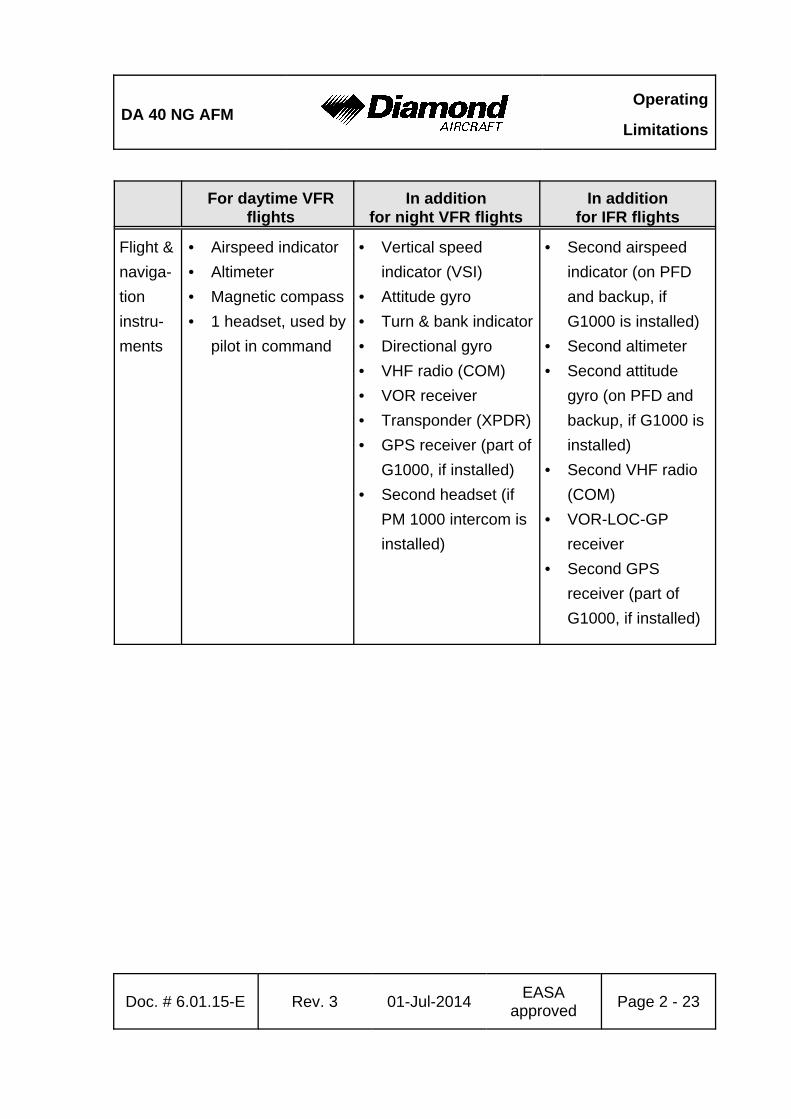
Minimum Operational Equipment (Serviceable)
The following table lists the minimum serviceable equipment required by JAR-23.
Additional minimum equipment for the intended operation may be required by
national operating rules and also depends on the route to be flown.
NOTE
Many of the items of minimum equipment listed in the
following table are integrated in the G1000 (if installed).
DA 40 NG AFMOperating
Limitations
Doc. # 6.01.15-E Rev. 3 01-Jul-2014EASA
approvedPage 2 - 23
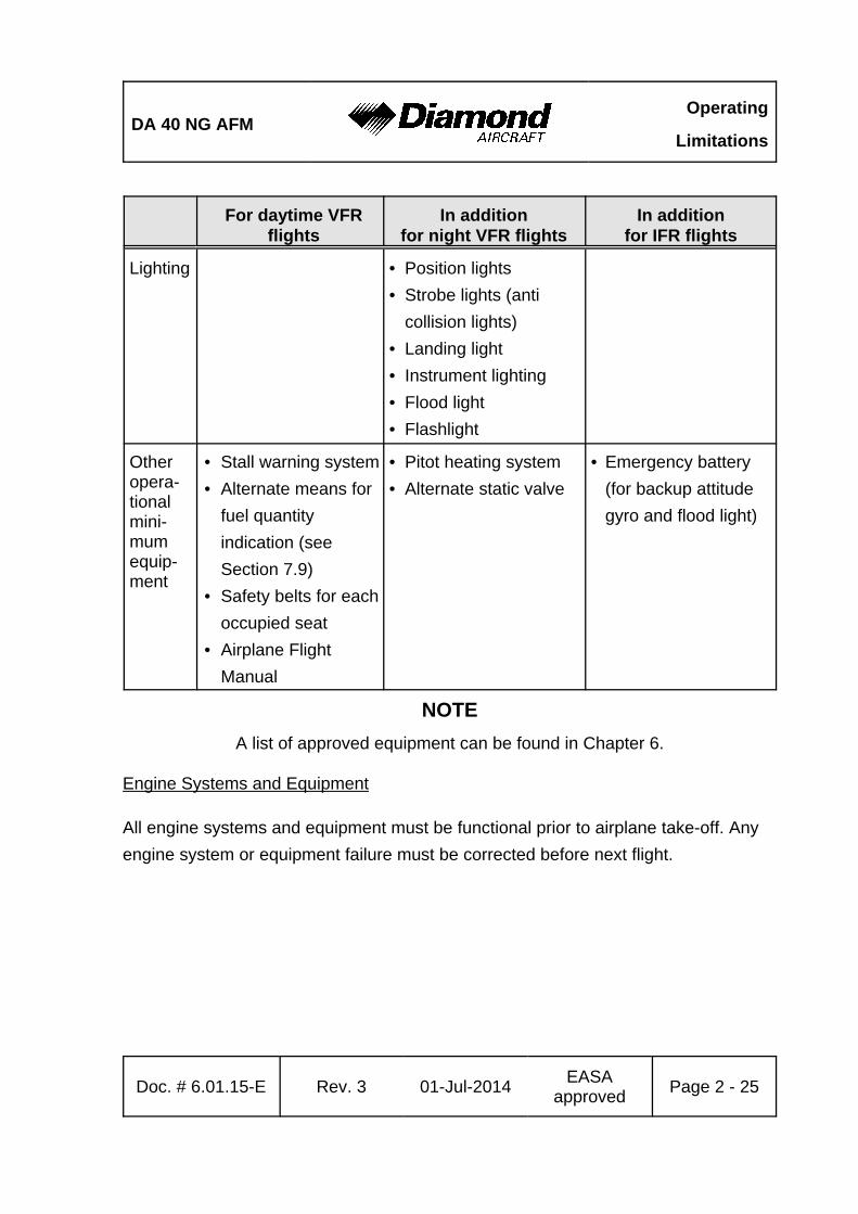
For daytime VFRflights
In additionfor night VFR flights
In additionfor IFR flights
Flight &
naviga-
tion
instru-
ments
• Airspeed indicator
• Altimeter
• Magnetic compass
• 1 headset, used by
pilot in command
• Vertical speed
indicator (VSI)
• Attitude gyro
• Turn & bank indicator
• Directional gyro
• VHF radio (COM)
• VOR receiver
• Transponder (XPDR)
• GPS receiver (part of
G1000, if installed)
• Second headset (if
PM 1000 intercom is
installed)
• Second airspeed
indicator (on PFD
and backup, if
G1000 is installed)
• Second altimeter
• Second attitude
gyro (on PFD and
backup, if G1000 is
installed)
• Second VHF radio
(COM)
• VOR-LOC-GP
receiver
• Second GPS
receiver (part of
G1000, if installed)
Operating
LimitationsDA 40 NG AFM
For daytime VFRflights
In additionfor night VFR flights
In additionfor IFR flights
Page 2 - 24 Rev. 3 01-Jul-2014EASA
approvedDoc. # 6.01.15-E
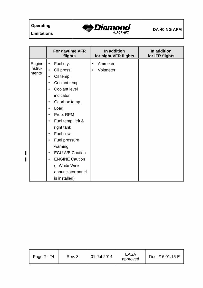
Engineinstru-ments
• Fuel qty.
• Oil press.
• Oil temp.
• Coolant temp.
• Coolant level
indicator
• Gearbox temp.
• Load
• Prop. RPM
• Fuel temp. left &
right tank
• Fuel flow
• Fuel pressure
warning
• ECU A/B Caution'
• ENGINE Caution'
(if White Wire
annunciator panel
is installed)
• Ammeter
• Voltmeter
DA 40 NG AFMOperating
Limitations
For daytime VFRflights
In additionfor night VFR flights
In additionfor IFR flights
Doc. # 6.01.15-E Rev. 3 01-Jul-2014EASA
approvedPage 2 - 25
Lighting • Position lights
• Strobe lights (anti
collision lights)
• Landing light
• Instrument lighting
• Flood light
• Flashlight
Otheropera-tionalmini-mumequip-ment
• Stall warning system
• Alternate means for
fuel quantity
indication (see
Section 7.9)
• Safety belts for each
occupied seat
• Airplane Flight
Manual
• Pitot heating system
• Alternate static valve
• Emergency battery
(for backup attitude
gyro and flood light)
NOTE
A list of approved equipment can be found in Chapter 6.
Engine Systems and Equipment
All engine systems and equipment must be functional prior to airplane take-off. Any
engine system or equipment failure must be corrected before next flight.
Operating
LimitationsDA 40 NG AFM
Page 2 - 26 Rev. 3 01-Jul-2014EASA
approvedDoc. # 6.01.15-E
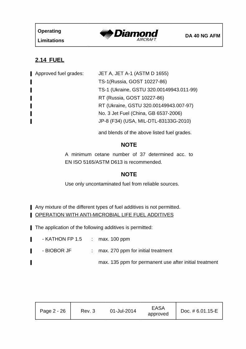
2.14 FUEL
Approved fuel grades: JET A, JET A-1 (ASTM D 1655)'
TS-1(Russia, GOST 10227-86)'
TS-1 (Ukraine, GSTU 320.00149943.011-99)'
RT (Russia, GOST 10227-86)'
RT (Ukraine, GSTU 320.00149943.007-97)'
No. 3 Jet Fuel (China, GB 6537-2006)'
JP-8 (F34) (USA, MIL-DTL-83133G-2010)'
and blends of the above listed fuel grades.
NOTE
A minimum cetane number of 37 determined acc. to
EN ISO 5165/ASTM D613 is recommended.
NOTE
Use only uncontaminated fuel from reliable sources.
Any mixture of the different types of fuel additives is not permitted.'
OPERATION WITH ANTI-MICROBIAL LIFE FUEL ADDITIVES'
The application of the following additives is permitted:'
- KATHON FP 1.5 : max. 100 ppm'
- BIOBOR JF : max. 270 ppm for initial treatment'
max. 135 ppm for permanent use after initial treatment '
DA 40 NG AFMOperating
Limitations
Doc. # 6.01.15-E Rev. 3 01-Jul-2014EASA
approvedPage 2 - 27
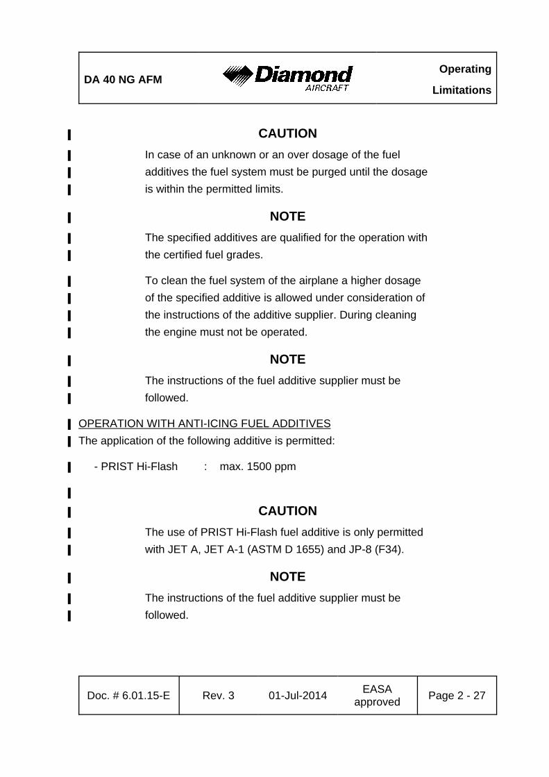
CAUTION'
In case of an unknown or an over dosage of the fuel'
additives the fuel system must be purged until the dosage'
is within the permitted limits.'
NOTE'
The specified additives are qualified for the operation with'
the certified fuel grades.'
To clean the fuel system of the airplane a higher dosage'
of the specified additive is allowed under consideration of'
the instructions of the additive supplier. During cleaning'
the engine must not be operated.'
NOTE'
The instructions of the fuel additive supplier must be'
followed.'
OPERATION WITH ANTI-ICING FUEL ADDITIVES'
The application of the following additive is permitted:'
- PRIST Hi-Flash : max. 1500 ppm'
'
CAUTION'
The use of PRIST Hi-Flash fuel additive is only permitted'
with JET A, JET A-1 (ASTM D 1655) and JP-8 (F34).'
NOTE'
The instructions of the fuel additive supplier must be'
followed.'
Operating
LimitationsDA 40 NG AFM
Page 2 - 28 Rev. 3 01-Jul-2014EASA
approvedDoc. # 6.01.15-E
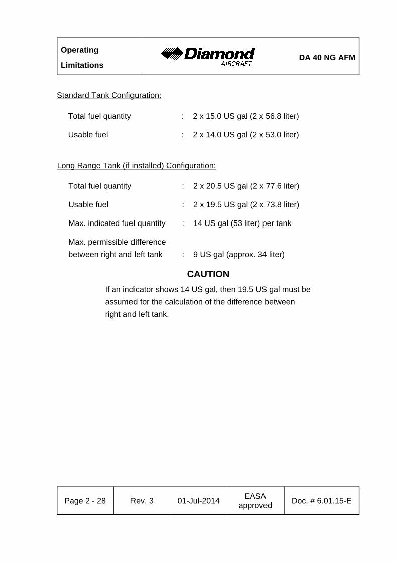
Standard Tank Configuration:
Total fuel quantity : 2 x 15.0 US gal (2 x 56.8 liter)
Usable fuel : 2 x 14.0 US gal (2 x 53.0 liter)
Long Range Tank (if installed) Configuration:
Total fuel quantity : 2 x 20.5 US gal (2 x 77.6 liter)
Usable fuel : 2 x 19.5 US gal (2 x 73.8 liter)
Max. indicated fuel quantity : 14 US gal (53 liter) per tank
Max. permissible difference
between right and left tank : 9 US gal (approx. 34 liter)
CAUTION
If an indicator shows 14 US gal, then 19.5 US gal must be
assumed for the calculation of the difference between
right and left tank.
DA 40 NG AFMOperating
Limitations
Doc. # 6.01.15-E Rev. 3 01-Jul-2014EASA
approvedPage 2 - 29
max. usable fuel: 2 x 19.5 US gal* Max. indicated fuel quantity: 2 x 14 US gal
* Refer to AFM to use entire tank capacity
* Max. difference LH/RH tank: 9 US gal
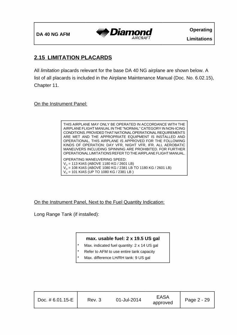
2.15 LIMITATION PLACARDS
All limitation placards relevant for the base DA 40 NG airplane are shown below. A
list of all placards is included in the Airplane Maintenance Manual (Doc. No. 6.02.15),
Chapter 11.
On the Instrument Panel:
THIS AIRPLANE MAY ONLY BE OPERATED IN ACCORDANCE WITH THEAIRPLANE FLIGHT MANUAL IN THE "NORMAL" CATEGORY IN NON-ICINGCONDITIONS. PROVIDED THAT NATIONAL OPERATIONAL REQUIREMENTSARE MET AND THE APPROPRIATE EQUIPMENT IS INSTALLED ANDOPERATIONAL, THIS AIRPLANE IS APPROVED FOR THE FOLLOWINGKINDS OF OPERATION: DAY VFR, NIGHT VFR, IFR. ALL AEROBATICMANEUVERS INCLUDING SPINNING ARE PROHIBITED. FOR FURTHEROPERATIONAL LIMITATIONS REFER TO THE AIRPLANE FLIGHT MANUAL.
OPERATING MANEUVERING SPEED:VO = 113 KIAS (ABOVE 1180 KG / 2601 LB)VO = 108 KIAS (ABOVE 1080 KG / 2381 LB TO 1180 KG / 2601 LB)VO = 101 KIAS (UP TO 1080 KG / 2381 LB )
On the Instrument Panel, Next to the Fuel Quantity Indication:
Long Range Tank (if installed):
Operating
LimitationsDA 40 NG AFM
Page 2 - 30 Rev. 3 01-Jul-2014EASA
approvedDoc. # 6.01.15-E
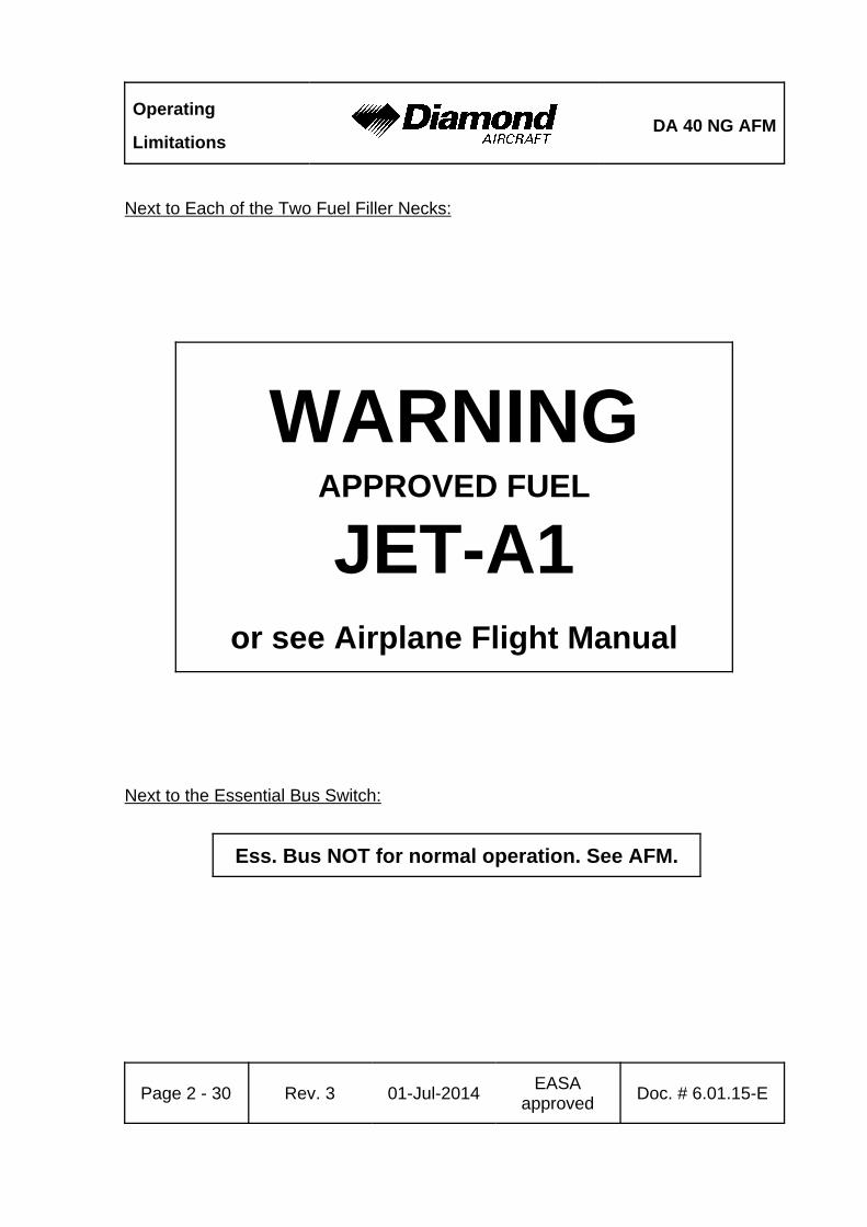
WARNINGAPPROVED FUEL
JET-A1or see Airplane Flight Manual
Next to Each of the Two Fuel Filler Necks:
Next to the Essential Bus Switch:
Ess. Bus NOT for normal operation. See AFM.
DA 40 NG AFMOperating
Limitations
Doc. # 6.01.15-E Rev. 3 01-Jul-2014EASA
approvedPage 2 - 31
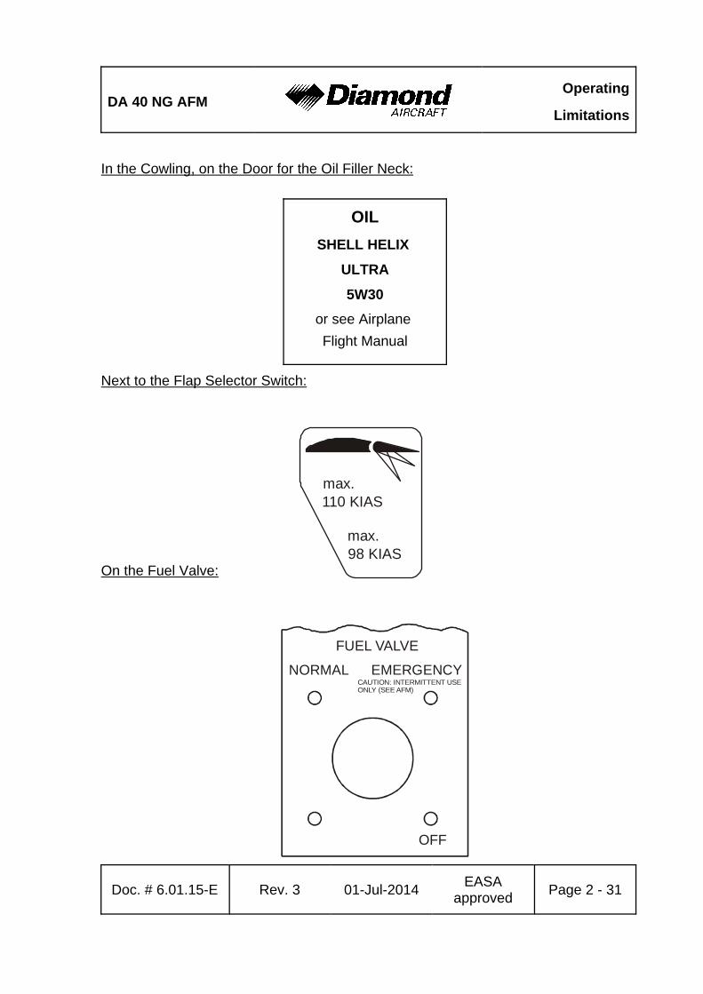
OIL
SHELL HELIX
ULTRA
5W30
or see Airplane
Flight Manual
max.98 KIAS
max.110 KIAS
NORMAL EMERGENCY
FUEL VALVE
CAUTION: INTERMITTENT USEONLY (SEE AFM)
OFF
In the Cowling, on the Door for the Oil Filler Neck:
Next to the Flap Selector Switch:
On the Fuel Valve:

Operating
LimitationsDA 40 NG AFM
Page 2 - 32 Rev. 3 01-Jul-2014EASA
approvedDoc. # 6.01.15-E
Max.5 kg/11 lb
Next to the Baggage Compartment:
Baggage Tube Compartment:
Baggage Tray (if OÄM 40-164 installed, extended baggage compartment):
Max.30 kg/66 lb

DA 40 NG AFMOperating
Limitations
Doc. # 6.01.15-E Rev. 3 01-Jul-2014EASA
approvedPage 2 - 33
COCKPIT BAGGAGECOMPARTMENT
MAX. 45 kg [100 lb]ARM: 3.89 m [153.1”]
BAGGAGEEXTENSIONMAX. 18 kg [40 lb]ARM: 4.54 m [178.7”]
MAX. BAGGAGE TOTAL (COCKPIT BAGGAGECOMPARTMENT & EXTENSION): 45 kg [100 lb]CAUTION: OBSERVE WEIGHT AND BALANCE LIMITATIONS SEE AIRPLANE FLIGHT MANUAL CHAPTER 6
If Short Baggage Extension (OÄM 40-331) is carried out:
Operating
LimitationsDA 40 NG AFM
Page 2 - 34 Rev. 3 01-Jul-2014EASA
approvedDoc. # 6.01.15-E
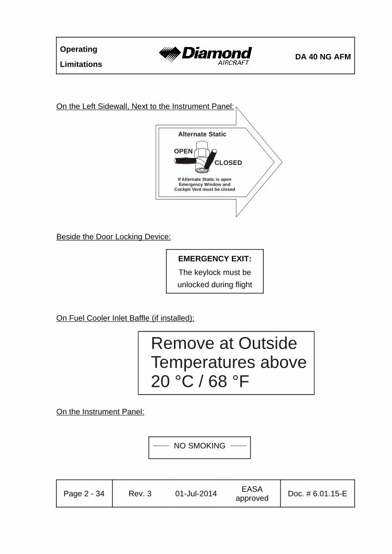
EMERGENCY EXIT:
The keylock must be
unlocked during flight
Remove at OutsideTemperatures above20 °C / 68 °F
Alternate Static
OPEN
CLOSED
If Alternate Static is openEmergency Window and
Cockpit Vent must be closed
On the Left Sidewall, Next to the Instrument Panel:
Beside the Door Locking Device:
On Fuel Cooler Inlet Baffle (if installed):
On the Instrument Panel:
______ NO SMOKING ______

DA 40 NG AFMOperating
Limitations
Doc. # 6.01.15-E Rev. 3 01-Jul-2014EASA
approvedPage 2 - 35
2.16 OTHER LIMITATIONS
2.16.1 TEMPERATURE
The airplane may only be operated when its temperature prior to operation is not less
than -40 °C (-40 °F).'
With the airplane cold soaked and its temperature below -20 °C (-4 °F) the use of an
external pre-heater for the engine and pilot compartment prior to operation is
mandatory.
The airplane may only be operated with the fuel cooler inlet baffle installed when the
outside air temperature at take-off does not exceed 20 EC (68 EF).
If the outside air temperature at take-off is below -30°C (-22°F) the coolant radiator'
inlet baffle (OÄM 40-364) must be installed. The airplane may only be operated with'
the coolant radiator inlet baffle, if the outside air temperature at take-off does not'
exceed 0°C (32°F).'
With the airplane cold soaked and its temperature below -30°C (-22°F) the batterries'
must be pre-heated (OÄM 40-363) prior to operation.'
2.16.2 BATTERY CHARGE
Take-off for a Night VFR or IFR flight with an empty main battery is not permitted.
The use of an external power supply for engine starting with an empty airplane main
battery is not permitted if the subsequent flight is intended to be a Night VFR or an
IFR flight. In this case the airplane main battery must be charged first.
2.16.3 EMERGENCY SWITCH
IFR flights are not permitted when the seal on the emergency switch is broken.
Operating
LimitationsDA 40 NG AFM
Page 2 - 36 Rev. 3 01-Jul-2014EASA
approvedDoc. # 6.01.15-E
2.16.4 DOOR LOCKING DEVICE
The canopy and the passenger door must not be key locked during operation of the
airplane.
2.16.5 ELECTRONIC EQUIPMENT
The use and switching on of electronic equipment other than that which is part of the
equipment of the airplane is not permitted, as it could lead to interference with the
airplane’s avionics.
Examples of undesirable items of equipment are:
- Mobile telephones
- Remote radio controls
- Video screens employing CRTs
- Minidisc recorders when in the record mode
This list is not exhaustive.
The use of laptop computers, including those with CD-ROM drives, CD and minidisc
players in the replay mode, cassette players and video cameras is permitted. All this
equipment however should be switched off for take-off and landing.
2.16.6 SMOKING
Smoking in the airplane is not permitted.
2.16.7 USE OF THE SUN VISORS
The sun visors (if installed, OÄM 40-327) may only be used during cruise. During all
other phases of flight the sun visors must be locked in the fully upward position.
DA 40 NG AFMEmergency
Procedures
Doc. # 6.01.15-E Rev. 3 01-Jul-2014 Page 3 - 1
CHAPTER 3
EMERGENCY PROCEDURES
Page
3.1 INTRODUCTION . . . . . . . . . . . . . . . . . . . . . . . . . . . . . . . . . . . . . . . 3-3
3.1.1 GENERAL . . . . . . . . . . . . . . . . . . . . . . . . . . . . . . . . . . . . . . . 3-3
3.1.2 CERTAIN AIRSPEEDS IN EMERGENCIES . . . . . . . . . . . . . 3-4
3.2 INSTRUMENT INDICATIONS IN PROHIBITED (RED) RANGE . . . 3-5
3.2.1 ENGINE TEMPERATURE . . . . . . . . . . . . . . . . . . . . . . . . . . 3-5
3.2.2 OIL TEMPERATURE . . . . . . . . . . . . . . . . . . . . . . . . . . . . . . 3-7
3.2.3 OIL PRESSURE . . . . . . . . . . . . . . . . . . . . . . . . . . . . . . . . . . 3-9
3.2.4 GEARBOX TEMPERATURE . . . . . . . . . . . . . . . . . . . . . . . 3-10
3.2.5 L/R FUEL TEMPERATURE . . . . . . . . . . . . . . . . . . . . . . . . 3-11
3.2.6 FUEL PRESSURE . . . . . . . . . . . . . . . . . . . . . . . . . . . . . . . 3-12
3.2.7 ALTERNATOR AMPS . . . . . . . . . . . . . . . . . . . . . . . . . . . . 3-13
3.2.8 ALTERNATOR FAIL . . . . . . . . . . . . . . . . . . . . . . . . . . . . . . 3-14
3.3 ENGINE PROBLEMS . . . . . . . . . . . . . . . . . . . . . . . . . . . . . . . . . . 3-15
3.3.1 ENGINE PROBLEMS ON GROUND . . . . . . . . . . . . . . . . . 3-15
3.3.2 ENGINE PROBLEMS DURING TAKE-OFF . . . . . . . . . . . . 3-16
3.3.3 ENGINE TROUBLESHOOTING IN FLIGHT . . . . . . . . . . . . 3-18
3.3.4 ENGINE FAILURE IN FLIGHT . . . . . . . . . . . . . . . . . . . . . . 3-21
3.3.5 RESTARTING THE ENGINE IN FLIGHT . . . . . . . . . . . . . . 3-22
3.3.6 DEFECTIVE RPM REGULATING SYSTEM . . . . . . . . . . . . 3-24
3.3.7 FUEL TRANSFER PUMP FAILURE . . . . . . . . . . . . . . . . . . 3-28
3.4 FAILURES IN THE ELECTRICAL SYSTEM . . . . . . . . . . . . . . . . . 3-30
3.4.1 COMPLETE FAILURE OF THE ELECTRICAL SYSTEM . . 3-30
3.4.2 HIGH CURRENT . . . . . . . . . . . . . . . . . . . . . . . . . . . . . . . . . 3-31
3.4.3 STARTER MALFUNCTION . . . . . . . . . . . . . . . . . . . . . . . . . 3-32

Emergency
ProceduresDA 40 NG AFM
Page 3 - 2 Rev. 3 01-Jul-2014 Doc. # 6.01.15-E
3.5 SMOKE AND FIRE . . . . . . . . . . . . . . . . . . . . . . . . . . . . . . . . . . . . 3-33
3.5.1 SMOKE AND FIRE ON GROUND . . . . . . . . . . . . . . . . . . . 3-33
3.5.2 SMOKE AND FIRE DURING TAKE-OFF . . . . . . . . . . . . . . 3-35
3.5.3 SMOKE AND FIRE IN FLIGHT . . . . . . . . . . . . . . . . . . . . . . 3-38
3.6 GLIDING . . . . . . . . . . . . . . . . . . . . . . . . . . . . . . . . . . . . . . . . . . . . 3-40
3.7 EMERGENCY LANDINGS . . . . . . . . . . . . . . . . . . . . . . . . . . . . . . 3-41
3.7.1 EMERGENCY LANDING WITH ENGINE OFF . . . . . . . . . . 3-41
3.7.2 LANDING WITH A DEFECTIVE TIRE ON THE MAIN LANDING
GEAR . . . . . . . . . . . . . . . . . . . . . . . . . . . . . . . . . . . . . . . . . 3-43
3.7.3 LANDING WITH DEFECTIVE BRAKES . . . . . . . . . . . . . . . 3-44
3.8 RECOVERY FROM AN UNINTENTIONAL SPIN . . . . . . . . . . . . . 3-45
3.9 OTHER EMERGENCIES . . . . . . . . . . . . . . . . . . . . . . . . . . . . . . . 3-46
3.9.1 ICING . . . . . . . . . . . . . . . . . . . . . . . . . . . . . . . . . . . . . . . . . 3-46
3.9.2 SUSPICION OF CARBON MONOXIDE CONTAMINATION IN THE
CABIN . . . . . . . . . . . . . . . . . . . . . . . . . . . . . . . . . . . . . . . . 3-47
3.9.3 UNLOCKED DOORS . . . . . . . . . . . . . . . . . . . . . . . . . . . . . 3-48
NOTE
Procedures for uncritical system faults are given in Chapter
4B - ABNORMAL OPERATING PROCEDURES.
DA 40 NG AFMEmergency
Procedures
Doc. # 6.01.15-E Rev. 3 01-Jul-2014 Page 3 - 3
3.1 INTRODUCTION
3.1.1 GENERAL
This Chapter contains checklists as well as the description of recommended procedures
to be followed in the event of an emergency. Engine failure or other airplane-related
emergencies are most unlikely to occur if the prescribed procedures for pre-flight checks
and airplane maintenance are followed.
If, nonetheless, an emergency does arise, the guidelines given here should be followed
and applied in order to clear the problem.
As it is impossible to foresee all kinds of emergencies and cover them in this Airplane
Flight Manual, a thorough understanding of the airplane by the pilot is, in addition to his
knowledge and experience, an essential factor in the solution of any problems which may
arise.
WARNING
In each emergency, control over the flight attitude and the
preparation of a possible emergency landing have priority
over attempts to solve the current problem ("first fly the
aircraft"). Prior to the flight the pilot must consider the
suitability of the terrain for an emergency landing for each
phase of the flight. For a safe flight the pilot must constantly
keep a safe minimum flight altitude. Solutions for various
adverse scenarios should be thought over in advance. Thus
it should be guaranteed that the pilot is at no time shocked
by an engine failure and that he can act calmly and with
determination.
Emergency
ProceduresDA 40 NG AFM
Page 3 - 4 Rev. 3 01-Jul-2014 Doc. # 6.01.15-E
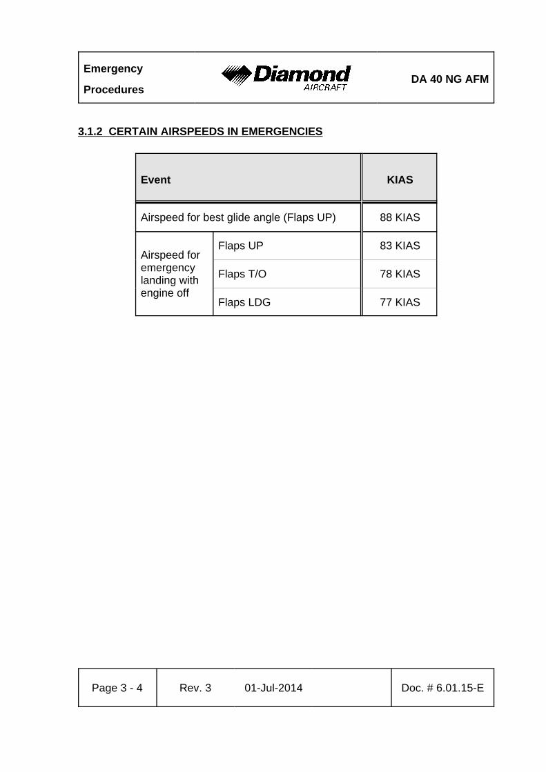
3.1.2 CERTAIN AIRSPEEDS IN EMERGENCIES
Event KIAS
Airspeed for best glide angle (Flaps UP) 88 KIAS
Airspeed foremergencylanding withengine off
Flaps UP 83 KIAS
Flaps T/O 78 KIAS
Flaps LDG 77 KIAS
DA 40 NG AFMEmergency
Procedures
Doc. # 6.01.15-E Rev. 3 01-Jul-2014 Page 3 - 5
3.2 INSTRUMENT INDICATIONS IN PROHIBITED (RED) RANGE
3.2.1 ENGINE TEMPERATURE
Engine coolant temperature is in the upper red range (too high / above 105 °C).
Coolant temperatures above the limit value of 105 °C can lead to a total loss of power
due to engine failure.
- Check for COOL LVL (if G1000 is installed) or WATERLEV (if SED is installed)
caution message (low coolant level).
COOL LVL (if G1000 is installed) or WATERLEV (if SED is installed) Caution Message
Not Displayed:
During climb:
- Reduce power by 10 % or more as required.
- Increase airspeed by 10 KIAS or more as required.
- If the coolant temperature does not reach the green range within 60 seconds, reduce
power as far as possible and increase airspeed.
CONTINUED
Emergency
ProceduresDA 40 NG AFM
Page 3 - 6 Rev. 3 01-Jul-2014 Doc. # 6.01.15-E
During cruise:
- Reduce power, or
- Increase airspeed, if necessary by initiating a descent.
- Check coolant temperature in green range.
CAUTION
If high coolant temperature is indicated and the COOL LVL
(if G1000 is installed) or WATERLEV (if SED is installed)
caution message is not displayed, it can be assumed that
there is no technical defect in the cooling system and that the
above mentioned procedure can decrease the temperature(s).
This might not be the case if the coolant temperature does
not return to the green range. In this case perform a
precautionary landing on the nearest suitable airfield. Prepare
for an engine failure in accordance with 3.3.4 - ENGINE
FAILURE IN FLIGHT.
COOL LVL (if G1000 is installed) or WATERLEV (if SED is installed) Caution Message
Displayed:
- Reduce power.
- Expect loss of coolant.
WARNING
A further increase in coolant temperature must be expected.
Prepare for an engine failure in accordance with
3.3.4 - ENGINE FAILURE IN FLIGHT.
END OF CHECKLIST
DA 40 NG AFMEmergency
Procedures
Doc. # 6.01.15-E Rev. 3 01-Jul-2014 Page 3 - 7
3.2.2 OIL TEMPERATURE
Engine oil temperature is in the upper red range (too high / above 140 °C).
Oil temperatures above the limit value of 140 °C can lead to a total loss of power due
to engine failure.
- Check oil pressure.
If the Oil Pressure Is Outside of the Green Range (Lower Limit):
- Reduce power.
- Expect loss of engine oil.
WARNING
A further increase in oil temperature must be expected.
Prepare for an engine failure in accordance with 3.3.4 -
ENGINE FAILURE IN FLIGHT.
If the Oil Pressure Is Within the Green Range:
- Reduce power.
- Increase airspeed.
CONTINUED
Emergency
ProceduresDA 40 NG AFM
Page 3 - 8 Rev. 3 01-Jul-2014 Doc. # 6.01.15-E
CAUTION
If high oil temperature is announced and the oil pressure
indication is within the green range, it can be assumed that
there is no technical defect in the engine oil system and that
the above mentioned procedure can decrease the
temperature(s). This might not be the case if the oil
temperature does not return to the green range. In this case
perform a precautionary landing on the nearest suitable
airfield. Prepare for an engine failure in accordance with
3.3.4 - ENGINE FAILURE IN FLIGHT.
END OF CHECKLIST
DA 40 NG AFMEmergency
Procedures
Doc. # 6.01.15-E Rev. 3 01-Jul-2014 Page 3 - 9
3.2.3 OIL PRESSURE
Engine oil pressure is in the lower red range (too low / below 0.9 bar).
Oil pressures below the limit value of 0.9 bar can lead to a total loss of power due to engine
failure.
- Reduce power.
- Expect loss of oil.
WARNING
Land at the nearest suitable airfield. Prepare for an engine
failure in accordance with 3.3.4 - ENGINE FAILURE IN
FLIGHT.
END OF CHECKLIST
Emergency
ProceduresDA 40 NG AFM
Page 3 - 10 Rev. 3 01-Jul-2014 Doc. # 6.01.15-E
3.2.4 GEARBOX TEMPERATURE
Engine gearbox temperature is in the upper red range (too high / above 120 °C).
Gearbox temperatures above the limit value of 120 °C can lead to a total loss of power
due to engine failure.
- Reduce power.
- Increase airspeed.
CAUTION
At high ambient temperature conditions and/or at low
airspeeds with high power settings, it can be assumed that
there is no technical defect in the gearbox and that the above
mentioned procedure will decrease the temperature(s). This
might not be the case if the gearbox temperature does not
return to the green range. In this case perform a
precautionary landing on the nearest suitable airfield. Prepare
for an engine failure in accordance with 3.3.4 - ENGINE
FAILURE IN FLIGHT.
END OF CHECKLIST
DA 40 NG AFMEmergency
Procedures
Doc. # 6.01.15-E Rev. 3 01-Jul-2014 Page 3 - 11
3.2.5 L/R FUEL TEMPERATURE
Fuel temperature is in the upper red range (too high / above 60 °C).
Fuel temperatures above the limit value of 60 °C can lead to a noticeable reduction of
the high pressure pump efficiency.
- Reduce power.
- Increase airspeed.
CAUTION
At high ambient temperature conditions and/or at low
airspeeds with high power settings and low fuel quantities,
it can be assumed that the above mentioned procedure will
decrease the temperature(s). If the fuel temperature does not
return to the green range, perform a precautionary landing
on the nearest suitable airfield.
NOTE
Increased fuel temperature can occur when the fuel quantity
in the main tank is low. The fuel temperature can be
decreased by transferring fuel from the auxiliary to the main
tank.
END OF CHECKLIST
Emergency
ProceduresDA 40 NG AFM
Page 3 - 12 Rev. 3 01-Jul-2014 Doc. # 6.01.15-E
3.2.6 FUEL PRESSURE
Engine fuel pressure is low.
1. Fuel quantity . . . . . . . . . . . . . . . . . . . . . . . . . check
2. Fuel valve . . . . . . . . . . . . . . . . . . . . . . . . . . . . check ON
3. Fuel pumps . . . . . . . . . . . . . . . . . . . . . . . . . . ON
If FUEL PRESS (if G1000 is installed) or FUELPRESS (if SED is installed) Warning
Remains:
4. Fuel valve . . . . . . . . . . . . . . . . . . . . . . . . . . . . EMERGENCY
5. Fuel pumps . . . . . . . . . . . . . . . . . . . . . . . . . . OFF
If FUEL PRESS (if G1000 is installed) or FUELPRESS (if SED is installed) Warning Still
Remains:
WARNING
Imminent engine failure must be expected. Prepare for an
engine failure in accordance with 3.3.4 - ENGINE FAILURE
IN FLIGHT.
END OF CHECKLIST
DA 40 NG AFMEmergency
Procedures
Doc. # 6.01.15-E Rev. 3 01-Jul-2014 Page 3 - 13
3.2.7 ALTERNATOR AMPS
Engine alternator output is in the upper red range (too high / above 70 A).
This warning is indicated when the consumption of electrical power is too high.%
Possible reasons are:%
- A fault in wiring or equipment.%
1. Electrical equipment . . . . . . . . . . . . . . . . . . . switch OFF as necessary and%
possible to reduce electric load %
%
If the problem does not clear itself:%
%
2. Land on the nearest suitable airfield.%
END OF CHECKLIST
Emergency
ProceduresDA 40 NG AFM
Page 3 - 14 Rev. 3 01-Jul-2014 Doc. # 6.01.15-E
3.2.8 ALTERNATOR FAIL
Engine alternator has failed.
The batteries are the last remaining source of electrical power for about 30 minutes.
1. Circuit breakers . . . . . . . . . . . . . . . . . . . . . . check
2. ESSENTIAL BUS . . . . . . . . . . . . . . . . . . . . . ON
3. Electrical equipment . . . . . . . . . . . . . . . . . . . switch OFF all equipment which
is not needed
4. Land on the nearest suitable airfield.
WARNING
The ECU which is absolutely necessary for engine operation
needs electrical power. It is recommended to switch off all
electrical consumers and to land as soon as possible. Be
prepared for an engine failure and an emergency landing. For
a severe electrical failure a ECU backup battery system is
installed.
CAUTION
For cases in which the battery capacity is not sufficient to
reach a suitable airfield, an emergency battery is installed,
serving as an additional back-up system for the backup
attitude gyro (artificial horizon) and flood light. This battery
is switched on with the EMERGENCY switch, located on the
top left side of the instrument panel.
END OF CHECKLIST
DA 40 NG AFMEmergency
Procedures
Doc. # 6.01.15-E Rev. 3 01-Jul-2014 Page 3 - 15
3.3 ENGINE PROBLEMS
3.3.1 ENGINE PROBLEMS ON GROUND
1. POWER lever . . . . . . . . . . . . . . . . . . . . . . . . IDLE
2. Brakes . . . . . . . . . . . . . . . . . . . . . . . . . . . . . as required
NOTE
If considered necessary, the engine must be shut down.
Otherwise the cause of the problem must be established in
order to re-establish engine performance.
CAUTION
If the oil pressure is in the red range, the engine must be shut
down immediately.
WARNING
If the problem cannot be cleared, the airplane must not be
flown.
END OF CHECKLIST
Emergency
ProceduresDA 40 NG AFM
Page 3 - 16 Rev. 3 01-Jul-2014 Doc. # 6.01.15-E
3.3.2 ENGINE PROBLEMS DURING TAKE-OFF
(a) Take-Off Can Still Be Aborted (Sufficient Runway Length Available)
Land Straight Ahead:
1. POWER lever . . . . . . . . . . . . . . . . . . . . . . . . IDLE
On the Ground:
2. Brakes . . . . . . . . . . . . . . . . . . . . . . . . . . . . . as required
WARNING
If sufficient time is remaining, the risk of fire in the event of
a collision can be reduced as follows:
- Fuel valve . . . . . . . . . . . . . . . . . . OFF
- ENGINE MASTER . . . . . . . . . . . OFF
- ELECTRIC MASTER . . . . . . . . . . OFF
END OF CHECKLIST
DA 40 NG AFMEmergency
Procedures
Doc. # 6.01.15-E Rev. 3 01-Jul-2014 Page 3 - 17
(b) Take-Off Can No Longer Be Aborted
1. Airspeed . . . . . . . . . . . . . . . . . . . . . . . . . . . . immediate pitch down to avoid
airspeed reduction
WARNING
If, in the event of an engine problem occurring during take-off,
the take-off can no longer be aborted and a safe height has
not been reached, then a straight-ahead emergency landing
should be considered. Do not attempt to turn back to the
airfield. Turning back can be fatal.
If Time Allows:
2. POWER lever . . . . . . . . . . . . . . . . . . . . . . . . check MAX
3. Fuel pumps . . . . . . . . . . . . . . . . . . . . . . . . . . check ON
5. VOTER switch . . . . . . . . . . . . . . . . . . . . . . . check AUTO
WARNING
If the problem does not clear itself immediately, and the
engine is no longer producing sufficient power, then an
emergency landing must be carried out in accordance with
3.7.1 - EMERGENCY LANDING WITH ENGINE OFF.
END OF CHECKLIST
Emergency
ProceduresDA 40 NG AFM
Page 3 - 18 Rev. 3 01-Jul-2014 Doc. # 6.01.15-E
3.3.3 ENGINE TROUBLESHOOTING IN FLIGHT
WARNING
Control over the flight attitude has priority over attempts to
solve the current problem ("first fly the airplane").
1. Airspeed . . . . . . . . . . . . . . . . . . . . . . . . . . . . 88 KIAS
2. POWER lever . . . . . . . . . . . . . . . . . . . . . . . . MAX
NOTE
If the loss of power was due to unintentional setting of the
POWER lever, you may adjust the friction lock and continue
your flight.
If ECU A and ECU B Cautions Appear Simultaneously
- If the indicated LOAD remains unchanged, and
- if the perceived thrust is reduced, and
- if the engine noise level changes or the engine is running rough:
3. POWER lever . . . . . . . . . . . . . . . . . . . . . . . . . IDLE for 1 second
4. POWER lever . . . . . . . . . . . . . . . . . . . . . . . . . slowly increase to 1975 RPM
If the engine shows a power loss during the POWER lever increase:
5. POWER lever . . . . . . . . . . . . . . . . . . . . . . . . . IDLE for 1 second
6. POWER lever . . . . . . . . . . . . . . . . . . . . . . . . . slowly increase, stop prior to the
previously observed engine
power loss RPM
CONTINUED
DA 40 NG AFMEmergency
Procedures
Doc. # 6.01.15-E Rev. 3 01-Jul-2014 Page 3 - 19
WARNING
Do not increase the POWER lever past the propeller speed
of 1975 RPM or the setting determined in step 6. An increase
of engine power beyond this setting leads into another power
loss.
NOTE
With this power setting the engine can provide up to 65 %
load at the maximum propeller speed of 1975 RPM.
7. Land at the next suitable airfield.
Otherwise:
Depending on the situation the following attempts can be made to restore normal engine
operation:
3. Circuit breakers . . . . . . . . . . . . . . . . . . . . . . check / reset if necessary
If normal engine operation is restored continue flight and land as soon as possible.
Otherwise:
4. VOTER switch . . . . . . . . . . . . . . . . . . . . . . . swap between ECU A and B
If either ECU A or B setting restores normal engine operation then maintain ECU setting
and land as soon as possible.
CONTINUED
Emergency
ProceduresDA 40 NG AFM
Page 3 - 20 Rev. 3 01-Jul-2014 Doc. # 6.01.15-E
Otherwise:
5. VOTER switch . . . . . . . . . . . . . . . . . . . . . . . switch back to AUTO to retain
ECU redundancy
If normal engine operation is restored continue flight and land as soon as possible.
Otherwise:
6. Fuel valve . . . . . . . . . . . . . . . . . . . . . . . . . . . EMERGENCY
If normal engine operation is restored continue flight and land as soon as possible. Remain
within maximum allowable lateral imbalance.
Otherwise:
7. Fuel valve . . . . . . . . . . . . . . . . . . . . . . . . . . . NORMAL
8. Alternate air . . . . . . . . . . . . . . . . . . . . . . . . . OPEN
9. POWER lever . . . . . . . . . . . . . . . . . . . . . . . . apply power as required
If normal engine operation is restored continue flight and land as soon as practicable.
If normal engine operation could not be restored by following the procedures in this section
prepare for 3.3.4 - ENGINE FAILURE IN FLIGHT and land as soon as possible.
END OF CHECKLIST
DA 40 NG AFMEmergency
Procedures
Doc. # 6.01.15-E Rev. 3 01-Jul-2014 Page 3 - 21
3.3.4 ENGINE FAILURE IN FLIGHT
WARNING
Control over the flight attitude has priority over attempts to
solve the current problem ("first fly the airplane").
NOTE
As long as there is no major mechanical engine defect, the
propeller will continue to windmill.
1. Airspeed . . . . . . . . . . . . . . . . . . . . . . . . . . . . 88 KIAS
2. Flaps . . . . . . . . . . . . . . . . . . . . . . . . . . . . . . . UP
If the Remaining Altitude is Sufficient for an Restart Attempt:
Try to restart the engine, refer to 3.3.5 - RESTARTING THE ENGINE IN FLIGHT.
If the Remaining Altitude is NOT Sufficient for an Restart Attempt:
Carry out an emergency landing in accordance with 3.7.1 - EMERGENCY LANDING WITH
ENGINE OFF.
END OF CHECKLIST
Emergency
ProceduresDA 40 NG AFM
Page 3 - 22 Rev. 3 01-Jul-2014 Doc. # 6.01.15-E
3.3.5 RESTARTING THE ENGINE IN FLIGHT
NOTE
With a failed engine the propeller continues to windmill. A
stopped propeller indicates a major mechanical engine defect.
Starter assisted restart shall not be considered.
Maximum restart altitude:
16,400 ft pressure altitude . . . . . . . . . . . . . . . for immediate restarts
10,000 ft pressure altitude . . . . . . . . . . . . . . . for restarts within two minutes
NOTE
If the engine is allowed to cool down for more than two
minutes, a successful restart may not be possible.
1. Airspeed . . . . . . . . . . . . . . . . . . . . . . . . . . . 88 KIAS
2. POWER lever . . . . . . . . . . . . . . . . . . . . . . . . IDLE
3. VOTER switch . . . . . . . . . . . . . . . . . . . . . . . check AUTO
4. Fuel valve . . . . . . . . . . . . . . . . . . . . . . . . . . . check NORMAL
5. Alternate air . . . . . . . . . . . . . . . . . . . . . . . . . as required
6. Fuel quantity . . . . . . . . . . . . . . . . . . . . . . . . . check
7. Fuel transfer pump . . . . . . . . . . . . . . . . . . . . as required
8. ELECTRIC MASTER . . . . . . . . . . . . . . . . . . check ON
9. ENGINE MASTER . . . . . . . . . . . . . . . . . . . . check ON
CONTINUED
DA 40 NG AFMEmergency
Procedures
Doc. # 6.01.15-E Rev. 3 01-Jul-2014 Page 3 - 23
If Engine Does Not Start:
10. Fuel valve . . . . . . . . . . . . . . . . . . . . . . . . . . . EMERGENCY
If Engine Does Not Start Adopt Glide Configuration:
11. Flaps . . . . . . . . . . . . . . . . . . . . . . . . . . . . . . UP
12. Airspeed88 KIAS
NOTE
The glide ratio is 9.7; i.e., for every 1000 ft (305 m) of altitude
loss the maximum horizontal distance traveled in still air is
1.59 NM (2.94 km). During this the propeller will continue to
windmill.
Carry out an emergency landing in accordance with 3.7.1 -
EMERGENCY LANDING WITH ENGINE OFF.
CAUTION
Engine restart following an engine fire should only be
attempted if it is unlikely that a safe emergency landing can
be made. It must be expected that engine restart is impossible
after an engine fire.
13. AVIONIC MASTER . . . . . . . . . . . . . . . . . . . . ON, if required
END OF CHECKLIST
Emergency
ProceduresDA 40 NG AFM
Page 3 - 24 Rev. 3 01-Jul-2014 Doc. # 6.01.15-E
3.3.6 DEFECTIVE RPM REGULATING SYSTEM
WARNING
In case of defective RPM regulating system, reduced engine
performance should be anticipated.
CAUTION
Following a failure of the governor the RPM should be
adjusted with the POWER lever.
CAUTION
The POWER lever should be moved slowly, in order to avoid
over-speeding and excessively rapid RPM changes. The light
wooden propeller blades produce more rapid RPM changes
than metal blades.
(a) Oscillating RPM
1. Power setting . . . . . . . . . . . . . . . . . . . . . . . . change
If the Problem Does Not Clear:
2. VOTER switch . . . . . . . . . . . . . . . . . . . . . . . swap between ECU A and B
If the Problem Does Not Clear:
3. VOTER switch . . . . . . . . . . . . . . . . . . . . . . . AUTO
4. Land on the nearest suitable airfield.
END OF CHECKLIST
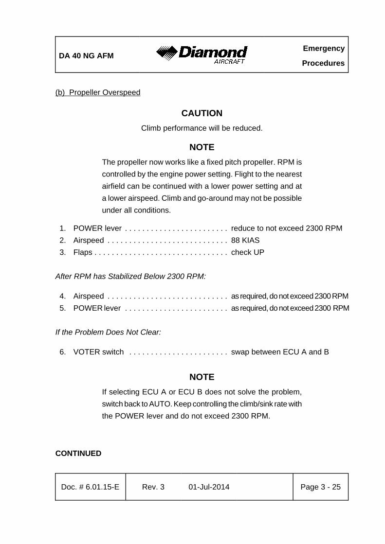
DA 40 NG AFMEmergency
Procedures
Doc. # 6.01.15-E Rev. 3 01-Jul-2014 Page 3 - 25
(b) Propeller Overspeed
CAUTION
Climb performance will be reduced.
NOTE
The propeller now works like a fixed pitch propeller. RPM is
controlled by the engine power setting. Flight to the nearest
airfield can be continued with a lower power setting and at
a lower airspeed. Climb and go-around may not be possible
under all conditions.
1. POWER lever . . . . . . . . . . . . . . . . . . . . . . . . reduce to not exceed 2300 RPM
2. Airspeed . . . . . . . . . . . . . . . . . . . . . . . . . . . . 88 KIAS
3. Flaps . . . . . . . . . . . . . . . . . . . . . . . . . . . . . . . check UP
After RPM has Stabilized Below 2300 RPM:
4. Airspeed . . . . . . . . . . . . . . . . . . . . . . . . . . . . as required, do not exceed 2300 RPM
5. POWER lever . . . . . . . . . . . . . . . . . . . . . . . . as required, do not exceed 2300 RPM
If the Problem Does Not Clear:
6. VOTER switch . . . . . . . . . . . . . . . . . . . . . . . swap between ECU A and B
NOTE
If selecting ECU A or ECU B does not solve the problem,
switch back to AUTO. Keep controlling the climb/sink rate with
the POWER lever and do not exceed 2300 RPM.
CONTINUED
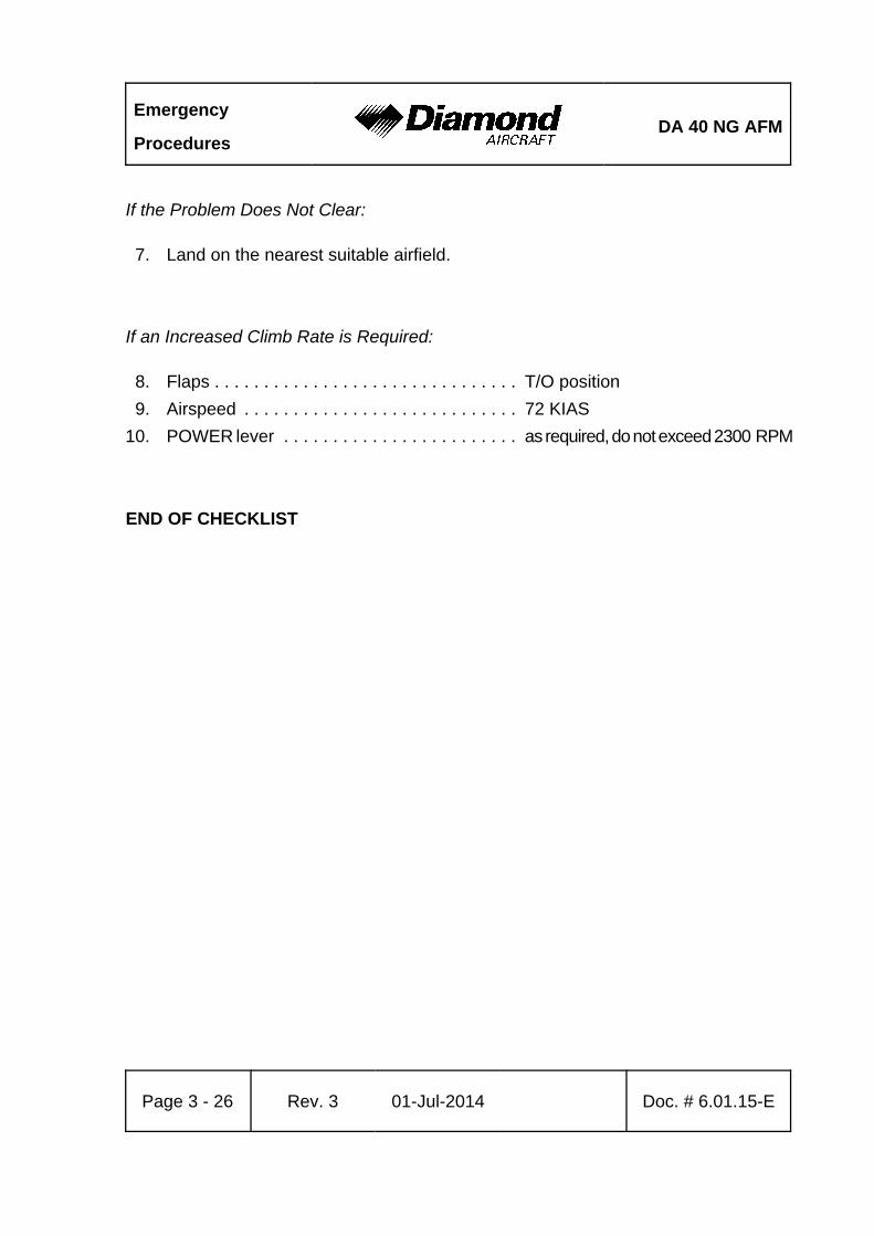
Emergency
ProceduresDA 40 NG AFM
Page 3 - 26 Rev. 3 01-Jul-2014 Doc. # 6.01.15-E
If the Problem Does Not Clear:
7. Land on the nearest suitable airfield.
If an Increased Climb Rate is Required:
8. Flaps . . . . . . . . . . . . . . . . . . . . . . . . . . . . . . . T/O position
9. Airspeed . . . . . . . . . . . . . . . . . . . . . . . . . . . . 72 KIAS
10. POWER lever . . . . . . . . . . . . . . . . . . . . . . . . as required, do not exceed 2300 RPM
END OF CHECKLIST
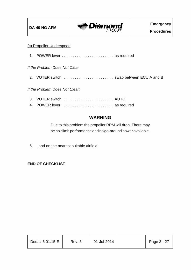
DA 40 NG AFMEmergency
Procedures
Doc. # 6.01.15-E Rev. 3 01-Jul-2014 Page 3 - 27
(c) Propeller Underspeed
1. POWER lever . . . . . . . . . . . . . . . . . . . . . . . . as required
If the Problem Does Not Clear
2. VOTER switch . . . . . . . . . . . . . . . . . . . . . . . swap between ECU A and B
If the Problem Does Not Clear:
3. VOTER switch . . . . . . . . . . . . . . . . . . . . . . . AUTO
4. POWER lever . . . . . . . . . . . . . . . . . . . . . . . as required
WARNING
Due to this problem the propeller RPM will drop. There may
be no climb performance and no go-around power available.
5. Land on the nearest suitable airfield.
END OF CHECKLIST
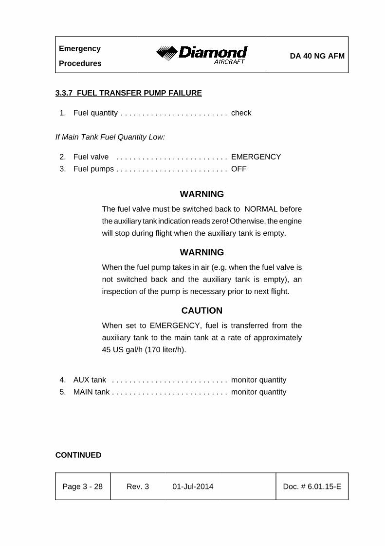
Emergency
ProceduresDA 40 NG AFM
Page 3 - 28 Rev. 3 01-Jul-2014 Doc. # 6.01.15-E
3.3.7 FUEL TRANSFER PUMP FAILURE
1. Fuel quantity . . . . . . . . . . . . . . . . . . . . . . . . . check
If Main Tank Fuel Quantity Low:
2. Fuel valve . . . . . . . . . . . . . . . . . . . . . . . . . . EMERGENCY
3. Fuel pumps . . . . . . . . . . . . . . . . . . . . . . . . . . OFF
WARNING
The fuel valve must be switched back to NORMAL before
the auxiliary tank indication reads zero! Otherwise, the engine
will stop during flight when the auxiliary tank is empty.
WARNING
When the fuel pump takes in air (e.g. when the fuel valve is
not switched back and the auxiliary tank is empty), an
inspection of the pump is necessary prior to next flight.
CAUTION
When set to EMERGENCY, fuel is transferred from the
auxiliary tank to the main tank at a rate of approximately
45 US gal/h (170 liter/h).
4. AUX tank . . . . . . . . . . . . . . . . . . . . . . . . . . . monitor quantity
5. MAIN tank . . . . . . . . . . . . . . . . . . . . . . . . . . . monitor quantity
CONTINUED
DA 40 NG AFMEmergency
Procedures
Doc. # 6.01.15-E Rev. 3 01-Jul-2014 Page 3 - 29
NOTE
AUX tank quantity must not be less than 1 US gal and
MAIN tank quantity must not be more than 14 US gal.
6. Fuel valve . . . . . . . . . . . . . . . . . . . . . . . . . . . NORMAL
7. Land as soon as practicable.
END OF CHECKLIST
Emergency
ProceduresDA 40 NG AFM
Page 3 - 30 Rev. 3 01-Jul-2014 Doc. # 6.01.15-E
3.4 FAILURES IN THE ELECTRICAL SYSTEM
3.4.1 COMPLETE FAILURE OF THE ELECTRICAL SYSTEM
1. Circuit breakers . . . . . . . . . . . . . . . . . . . . . . check IN
2. ESSENTIAL BUS . . . . . . . . . . . . . . . . . . . . . ON
If There Is Still No Electrical Power Available:
2. EMERGENCY switch (if installed) . . . . . . . . ON
3. Flood light, if necessary . . . . . . . . . . . . . . . . ON
4. POWER . . . . . . . . . . . . . . . . . . . . . . . . . . . . set based on lever positions
and engine noise
5. Prepare landing with flaps in the given position. Refer to 4B.5 - FAILURES IN FLAP
OPERATING SYSTEM.
6. Land on the nearest suitable airfield.
WARNING
Engine stoppage may occur, depending on the failure mode.
A backup battery is installed for the ECU to provide electrical
power solely to ECU B and its system for at least 30 minutes.
NOTE
The backup artificial horizon and the flood light will have
electrical power for at least 1.5 hours.
If G1000 is installed make use of the stand-by airspeed indicator and altimeter. Engine
power can be set via visual reference of the POWER lever position.
END OF CHECKLIST
DA 40 NG AFMEmergency
Procedures
Doc. # 6.01.15-E Rev. 3 01-Jul-2014 Page 3 - 31
3.4.2 HIGH CURRENT
If HIGH CURRENT (> 70 A) is indicated on the G1000 (if installed) or SED (if installed):
1. ESSENTIAL BUS . . . . . . . . . . . . . . . . . . . . . ON
2. ENGINE SYSTEM DISPLAY
(if G1000 is installed) . . . . . . . . . . . . . . . . . . select by pressing ENGINE and
SYSTEM softkey on MFD
3. Circuit breakers . . . . . . . . . . . . . . . . . . . . . . check IN
4. Ammeter/Voltmeter . . . . . . . . . . . . . . . . . . . monitor
5. Land on the nearest suitable airfield.
END OF CHECKLIST
Emergency
ProceduresDA 40 NG AFM
Page 3 - 32 Rev. 3 01-Jul-2014 Doc. # 6.01.15-E
3.4.3 STARTER MALFUNCTION
If the starter does not disengage from the engine after starting (Starter engaged warning
(STARTER) on the G1000 (if installed) or START on the White Wire annunciator (if
installed) illuminates after the engine has started):
On Ground:
1. POWER lever . . . . . . . . . . . . . . . . . . . . . . . . IDLE
2. ENGINE MASTER . . . . . . . . . . . . . . . . . . . . OFF
3. ELECTRIC MASTER . . . . . . . . . . . . . . . . . . OFF
Terminate flight preparation!
In Flight:
Land as soon as possible.
END OF CHECKLIST
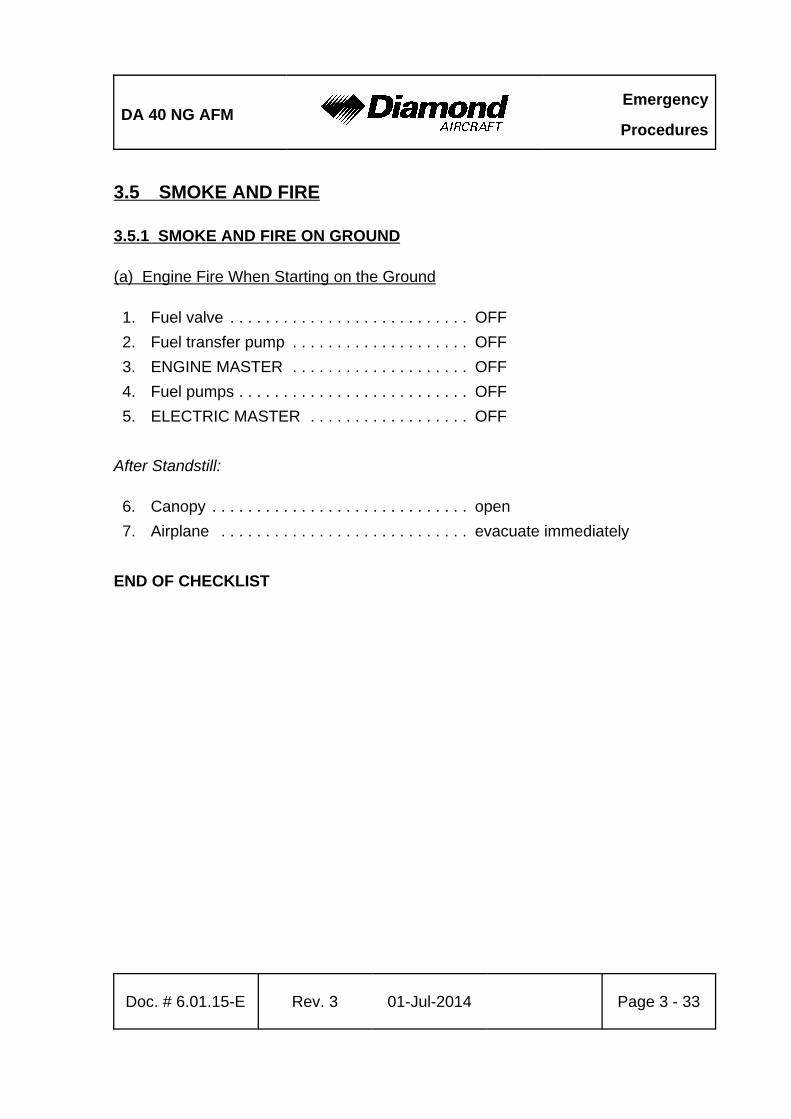
DA 40 NG AFMEmergency
Procedures
Doc. # 6.01.15-E Rev. 3 01-Jul-2014 Page 3 - 33
3.5 SMOKE AND FIRE
3.5.1 SMOKE AND FIRE ON GROUND
(a) Engine Fire When Starting on the Ground
1. Fuel valve . . . . . . . . . . . . . . . . . . . . . . . . . . . OFF
2. Fuel transfer pump . . . . . . . . . . . . . . . . . . . . OFF
3. ENGINE MASTER . . . . . . . . . . . . . . . . . . . . OFF
4. Fuel pumps . . . . . . . . . . . . . . . . . . . . . . . . . . OFF
5. ELECTRIC MASTER . . . . . . . . . . . . . . . . . . OFF
After Standstill:
6. Canopy . . . . . . . . . . . . . . . . . . . . . . . . . . . . . open
7. Airplane . . . . . . . . . . . . . . . . . . . . . . . . . . . . evacuate immediately
END OF CHECKLIST
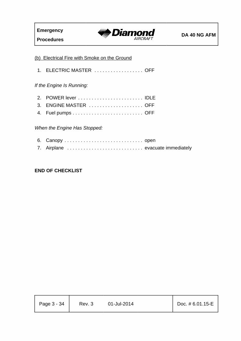
Emergency
ProceduresDA 40 NG AFM
Page 3 - 34 Rev. 3 01-Jul-2014 Doc. # 6.01.15-E
(b) Electrical Fire with Smoke on the Ground
1. ELECTRIC MASTER . . . . . . . . . . . . . . . . . . OFF
If the Engine Is Running:
2. POWER lever . . . . . . . . . . . . . . . . . . . . . . . . IDLE
3. ENGINE MASTER . . . . . . . . . . . . . . . . . . . . OFF
4. Fuel pumps . . . . . . . . . . . . . . . . . . . . . . . . . . OFF
When the Engine Has Stopped:
6. Canopy . . . . . . . . . . . . . . . . . . . . . . . . . . . . . open
7. Airplane . . . . . . . . . . . . . . . . . . . . . . . . . . . . evacuate immediately
END OF CHECKLIST
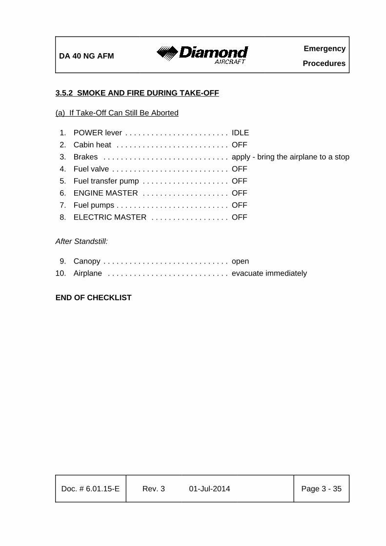
DA 40 NG AFMEmergency
Procedures
Doc. # 6.01.15-E Rev. 3 01-Jul-2014 Page 3 - 35
3.5.2 SMOKE AND FIRE DURING TAKE-OFF
(a) If Take-Off Can Still Be Aborted
1. POWER lever . . . . . . . . . . . . . . . . . . . . . . . . IDLE
2. Cabin heat . . . . . . . . . . . . . . . . . . . . . . . . . . OFF
3. Brakes . . . . . . . . . . . . . . . . . . . . . . . . . . . . . apply - bring the airplane to a stop
4. Fuel valve . . . . . . . . . . . . . . . . . . . . . . . . . . . OFF
5. Fuel transfer pump . . . . . . . . . . . . . . . . . . . . OFF
6. ENGINE MASTER . . . . . . . . . . . . . . . . . . . . OFF
7. Fuel pumps . . . . . . . . . . . . . . . . . . . . . . . . . . OFF
8. ELECTRIC MASTER . . . . . . . . . . . . . . . . . . OFF
After Standstill:
9. Canopy . . . . . . . . . . . . . . . . . . . . . . . . . . . . . open
10. Airplane . . . . . . . . . . . . . . . . . . . . . . . . . . . . evacuate immediately
END OF CHECKLIST
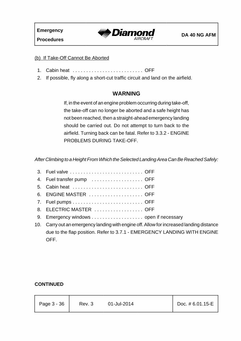
Emergency
ProceduresDA 40 NG AFM
Page 3 - 36 Rev. 3 01-Jul-2014 Doc. # 6.01.15-E
(b) If Take-Off Cannot Be Aborted
1. Cabin heat . . . . . . . . . . . . . . . . . . . . . . . . . . OFF
2. If possible, fly along a short-cut traffic circuit and land on the airfield.
WARNING
If, in the event of an engine problem occurring during take-off,
the take-off can no longer be aborted and a safe height has
not been reached, then a straight-ahead emergency landing
should be carried out. Do not attempt to turn back to the
airfield. Turning back can be fatal. Refer to 3.3.2 - ENGINE
PROBLEMS DURING TAKE-OFF.
After Climbing to a Height From Which the Selected Landing Area Can Be Reached Safely:
3. Fuel valve . . . . . . . . . . . . . . . . . . . . . . . . . . . OFF
4. Fuel transfer pump . . . . . . . . . . . . . . . . . . . OFF
5. Cabin heat . . . . . . . . . . . . . . . . . . . . . . . . . . OFF
6. ENGINE MASTER . . . . . . . . . . . . . . . . . . . . OFF
7. Fuel pumps . . . . . . . . . . . . . . . . . . . . . . . . . . OFF
8. ELECTRIC MASTER . . . . . . . . . . . . . . . . . . OFF
9. Emergency windows . . . . . . . . . . . . . . . . . . . open if necessary
10. Carry out an emergency landing with engine off. Allow for increased landing distance
due to the flap position. Refer to 3.7.1 - EMERGENCY LANDING WITH ENGINE
OFF.
CONTINUED
DA 40 NG AFMEmergency
Procedures
Doc. # 6.01.15-E Rev. 3 01-Jul-2014 Page 3 - 37
CAUTION
In case of extreme smoke development, the front canopy may
be unlatched during flight. This allows it to partially open, in
order to improve ventilation. The canopy will remain open in
this position. Flight characteristics will not be affected
significantly.
When Airplane Has Stopped:
11. Canopy . . . . . . . . . . . . . . . . . . . . . . . . . . . . . open
12. Airplane . . . . . . . . . . . . . . . . . . . . . . . . . . . . evacuate immediately
END OF CHECKLIST
Emergency
ProceduresDA 40 NG AFM
Page 3 - 38 Rev. 3 01-Jul-2014 Doc. # 6.01.15-E
3.5.3 SMOKE AND FIRE IN FLIGHT
WARNING
In the event of smoke or fire, prepare to land the airplane
without delay while completing fire suppression and/or smoke
evacuation procedures. If it cannot be visually verified that
the fire has been completely extinguished, whether the smoke
has cleared or not, land immediately.
(a) Engine Fire in Flight
1. Cabin heat . . . . . . . . . . . . . . . . . . . . . . . . . . OFF
2. Select appropriate emergency landing area.
When it Seems Certain That the Landing Area Will Be Reached:
3. Fuel valve . . . . . . . . . . . . . . . . . . . . . . . . . . . OFF
4. POWER lever . . . . . . . . . . . . . . . . . . . . . . . . MAX
5. Emergency windows . . . . . . . . . . . . . . . . . . . open if required
6. Land immediately. Refer to 3.7.1 - EMERGENCY LANDING WITH ENGINE OFF.
CAUTION
In case of extreme smoke development, the front canopy may
be unlatched during flight. This allows it to partially open, in
order to improve ventilation. The canopy will remain open in
this position. Flight characteristics will not be affected
significantly.
When Airplane Has Stopped:
7. Canopy . . . . . . . . . . . . . . . . . . . . . . . . . . . . . open
8. Airplane . . . . . . . . . . . . . . . . . . . . . . . . . . . . evacuate immediately
END OF CHECKLIST
DA 40 NG AFMEmergency
Procedures
Doc. # 6.01.15-E Rev. 3 01-Jul-2014 Page 3 - 39
(b) Electrical Fire with Smoke in Flight
1. EMERGENCY switch (if installed) . . . . . . . . ON
2. AVIONIC MASTER . . . . . . . . . . . . . . . . . . . . OFF
3. ELECTRIC MASTER . . . . . . . . . . . . . . . . . . OFF
4. Cabin heat . . . . . . . . . . . . . . . . . . . . . . . . . . OFF
5. Emergency windows . . . . . . . . . . . . . . . . . . . open if required
6. Land immediately. Refer to 3.7.1 - EMERGENCY LANDING WITH ENGINE OFF.
WARNING
Switching OFF the ELECTRIC MASTER will lead to total
failure of all electronic and electric equipment. Also affected
from this is the attitude gyro (artificial horizon).
However, by switching the EMERGENCY switch ON, if
installed, the emergency battery, if installed will supply power
to the attitude gyro (artificial horizon) and the flood light.
In case of extreme smoke development, the front canopy may
be unlatched during flight. This allows it to partially open, in
order to improve ventilation. The canopy will remain open in
this position. Flight characteristics will not be affected
significantly.
When Airplane Has Stopped:
7. Canopy . . . . . . . . . . . . . . . . . . . . . . . . . . . . . open
8. Airplane . . . . . . . . . . . . . . . . . . . . . . . . . . . . evacuate immediately
END OF CHECKLIST
Emergency
ProceduresDA 40 NG AFM
Page 3 - 40 Rev. 3 01-Jul-2014 Doc. # 6.01.15-E
3.6 GLIDING
1. Flaps . . . . . . . . . . . . . . . . . . . . . . . . . . . . . . . UP
2. Airspeed . . . . . . . . . . . . . . . . . . . . . . . . . . . . 88 KIAS
NOTE
The glide ratio is 9.7; i.e., for every 1000 ft (305 m) of altitude
loss the maximum horizontal distance traveled in still air is
1.59 NM (2.94 km). During this the propeller will continue to
windmill.
NOTE
For operation without wheel fairings the glide ratio is reduced
to 9.4; i.e., for every 1000 ft (305 m) of altitude loss the
maximum horizontal distance traveled in still air is 1.54 NM
(2.85 km). During this the propeller will continue to windmill.
END OF CHECKLIST
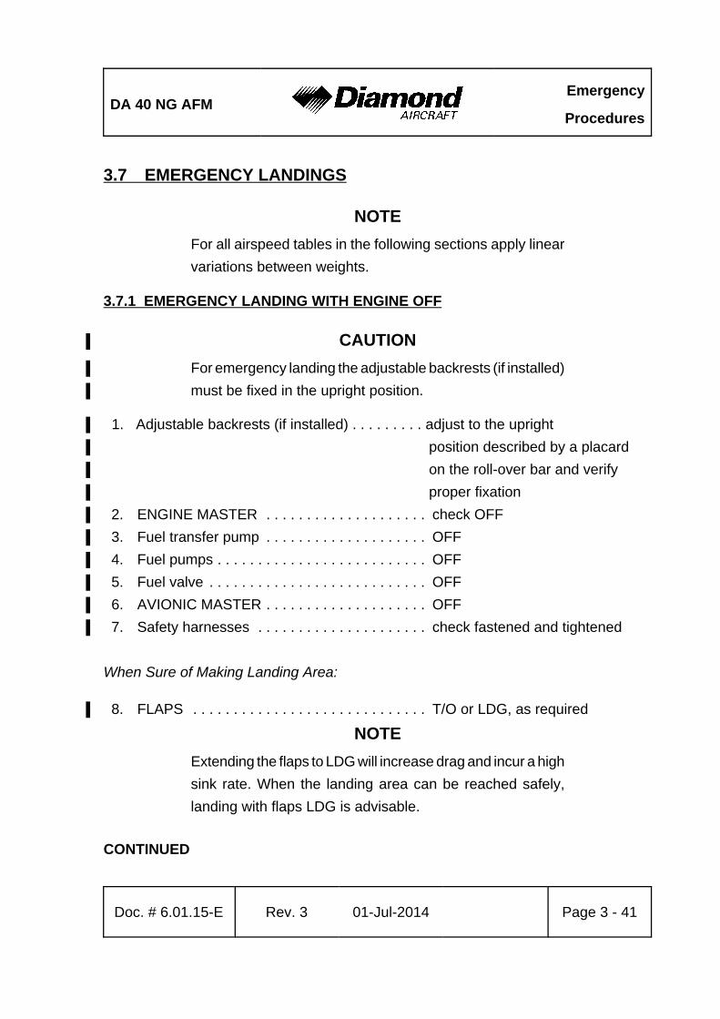
DA 40 NG AFMEmergency
Procedures
Doc. # 6.01.15-E Rev. 3 01-Jul-2014 Page 3 - 41
3.7 EMERGENCY LANDINGS
NOTE
For all airspeed tables in the following sections apply linear
variations between weights.
3.7.1 EMERGENCY LANDING WITH ENGINE OFF
CAUTION%
For emergency landing the adjustable backrests (if installed)%
must be fixed in the upright position.%
1. Adjustable backrests (if installed) . . . . . . . . . adjust to the upright %
position described by a placard %
on the roll-over bar and verify %
proper fixation%
2. ENGINE MASTER . . . . . . . . . . . . . . . . . . . . check OFF%
3. Fuel transfer pump . . . . . . . . . . . . . . . . . . . . OFF%
4. Fuel pumps . . . . . . . . . . . . . . . . . . . . . . . . . . OFF%
5. Fuel valve . . . . . . . . . . . . . . . . . . . . . . . . . . . OFF%
6. AVIONIC MASTER . . . . . . . . . . . . . . . . . . . . OFF%
7. Safety harnesses . . . . . . . . . . . . . . . . . . . . . check fastened and tightened%
When Sure of Making Landing Area:
8. FLAPS . . . . . . . . . . . . . . . . . . . . . . . . . . . . . T/O or LDG, as required%
NOTE
Extending the flaps to LDG will increase drag and incur a high
sink rate. When the landing area can be reached safely,
landing with flaps LDG is advisable.
CONTINUED

Emergency
ProceduresDA 40 NG AFM
Page 3 - 42 Rev. 3 01-Jul-2014 Doc. # 6.01.15-E
9. Approach speed . . . . . . . . . . . . . . . . . . . . . . see table below:%
%
Flaps940 kg
(2072 lb)
1000 kg
(2205 lb)
1080 kg
(2381 lb)
1160 kg
(2557 lb)
1216 kg
(2681 lb)
up to
1280 kg
(2822 lb)
T/O 68 KIAS 70 KIAS 73 KIAS 76 KIAS 77 KIAS 78 KIAS
LDG 66 KIAS 69 KIAS 72 KIAS 74 KIAS 76 KIAS 77 KIAS
10. ELECTRIC MASTER . . . . . . . . . . . . . . . . . . OFF%
11. Touch down . . . . . . . . . . . . . . . . . . . . . . . . . lowest practical speed%
END OF CHECKLIST
DA 40 NG AFMEmergency
Procedures
Doc. # 6.01.15-E Rev. 3 01-Jul-2014 Page 3 - 43
3.7.2 LANDING WITH A DEFECTIVE TIRE ON THE MAIN LANDING GEAR
CAUTION
A defective (e.g. burst) tire is not usually easy to detect. The
damage normally occurs during take-off or landing, and is
hardly noticeable during fast taxiing. It is only during the
roll-out after landing or at lower taxiing speeds that a
tendency to swerve occurs. Rapid and determined action is
then required.
1. Advise ATC.
2. Land the airplane at the edge of the runway that is located on the side of the intact
tire, so that changes in direction which must be expected during roll-out due to the
braking action of the defective tire can be corrected on the runway.
3. Land with one wing low. The wing on the side of the intact tire should be held low.
4. Direction should be maintained using the rudder. This should be supported by use
of the brake. It is possible that the brake must be applied strongly - if necessary to
the point where the wheel locks. The wide track of the landing gear will prevent the
airplane from tipping over a wide speed range. There is no pronounced tendency
to tip even when skidding.
END OF CHECKLIST
Emergency
ProceduresDA 40 NG AFM
Page 3 - 44 Rev. 3 01-Jul-2014 Doc. # 6.01.15-E
3.7.3 LANDING WITH DEFECTIVE BRAKES
In general, a landing on grass is recommended in order to reduce the landing run due
to the greater rolling resistance.
WARNING
If sufficient time is remaining, the risk of fire in the event of
a collision can be reduced as follows after a safe touch-down:
- Fuel valve . . . . . . . . . . . . . . . . . . OFF
- ENGINE MASTER . . . . . . . . . . . OFF
- Fuel pumps . . . . . . . . . . . . . . . . . OFF
- ELECTRIC MASTER . . . . . . . . . . OFF
END OF CHECKLIST
DA 40 NG AFMEmergency
Procedures
Doc. # 6.01.15-E Rev. 3 01-Jul-2014 Page 3 - 45
3.8 RECOVERY FROM AN UNINTENTIONAL SPIN
CAUTION
Steps 1 to 4 must be carried out immediately and
simultaneously.
1. POWER lever . . . . . . . . . . . . . . . . . . . . . . . . IDLE
2. Ailerons . . . . . . . . . . . . . . . . . . . . . . . . . . . . neutral
3. Rudder . . . . . . . . . . . . . . . . . . . . . . . . . . . . . full deflection against
direction of spin
4. Elevator (control stick) . . . . . . . . . . . . . . . . . fully forward
When Rotation Has Stopped:
5. Flaps . . . . . . . . . . . . . . . . . . . . . . . . . . . . . . . UP
6. Rudder . . . . . . . . . . . . . . . . . . . . . . . . . . . . . neutral
7. Elevator (control stick) . . . . . . . . . . . . . . . . . pull carefully
8. Return the airplane from a descending into a normal flight attitude. Do not exceed
the 'never exceed speed', vNE = 172 KIAS.
END OF CHECKLIST
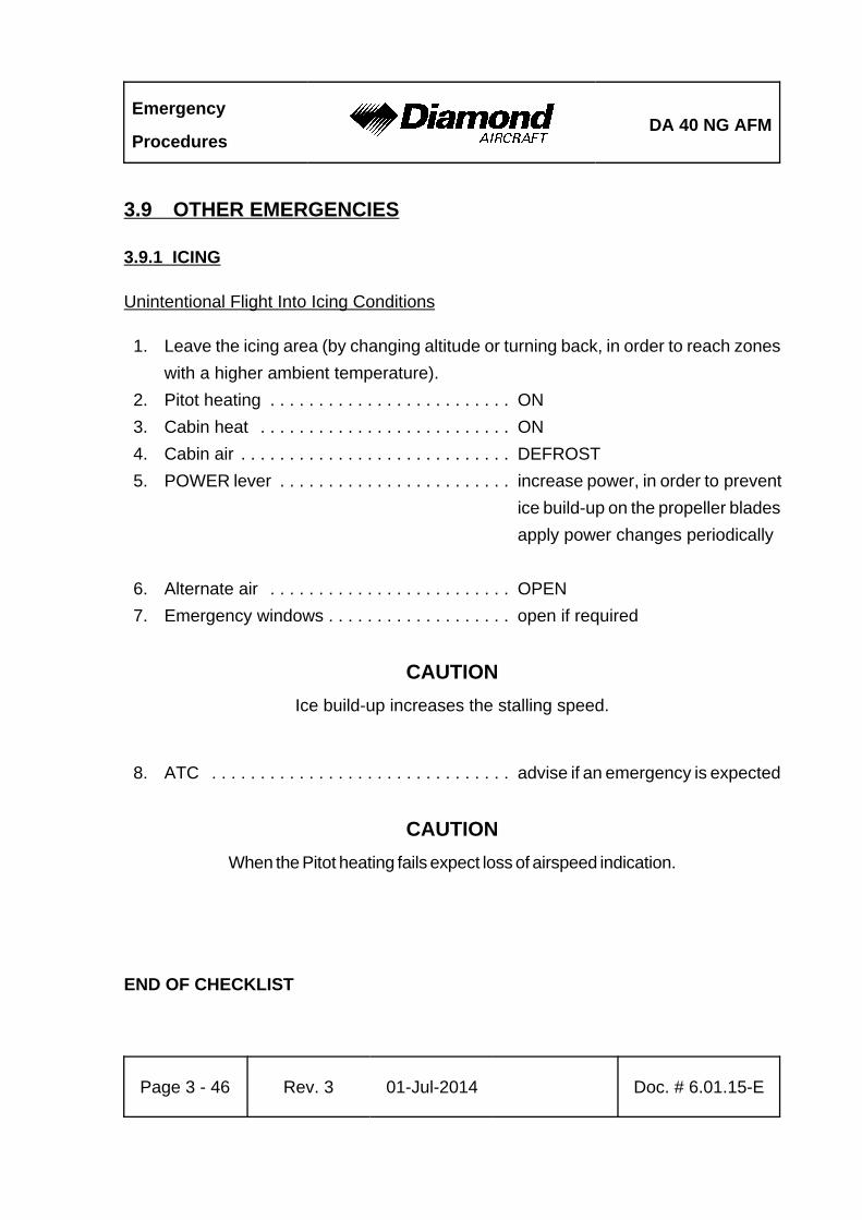
Emergency
ProceduresDA 40 NG AFM
Page 3 - 46 Rev. 3 01-Jul-2014 Doc. # 6.01.15-E
3.9 OTHER EMERGENCIES
3.9.1 ICING
Unintentional Flight Into Icing Conditions
1. Leave the icing area (by changing altitude or turning back, in order to reach zones
with a higher ambient temperature).
2. Pitot heating . . . . . . . . . . . . . . . . . . . . . . . . . ON
3. Cabin heat . . . . . . . . . . . . . . . . . . . . . . . . . . ON
4. Cabin air . . . . . . . . . . . . . . . . . . . . . . . . . . . . DEFROST
5. POWER lever . . . . . . . . . . . . . . . . . . . . . . . . increase power, in order to prevent
ice build-up on the propeller blades
apply power changes periodically
6. Alternate air . . . . . . . . . . . . . . . . . . . . . . . . . OPEN
7. Emergency windows . . . . . . . . . . . . . . . . . . . open if required
CAUTION
Ice build-up increases the stalling speed.
8. ATC . . . . . . . . . . . . . . . . . . . . . . . . . . . . . . . advise if an emergency is expected
CAUTION
When the Pitot heating fails expect loss of airspeed indication.
END OF CHECKLIST
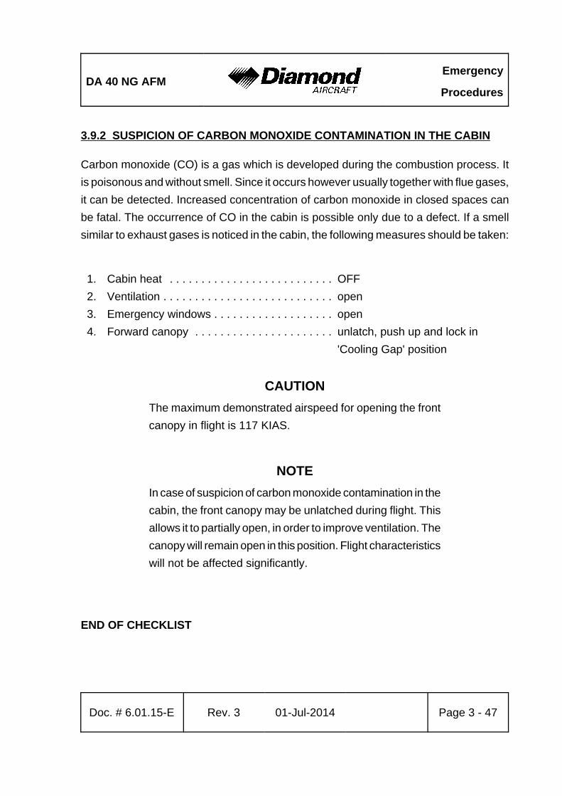
DA 40 NG AFMEmergency
Procedures
Doc. # 6.01.15-E Rev. 3 01-Jul-2014 Page 3 - 47
3.9.2 SUSPICION OF CARBON MONOXIDE CONTAMINATION IN THE CABIN
Carbon monoxide (CO) is a gas which is developed during the combustion process. It
is poisonous and without smell. Since it occurs however usually together with flue gases,
it can be detected. Increased concentration of carbon monoxide in closed spaces can
be fatal. The occurrence of CO in the cabin is possible only due to a defect. If a smell
similar to exhaust gases is noticed in the cabin, the following measures should be taken:
1. Cabin heat . . . . . . . . . . . . . . . . . . . . . . . . . . OFF
2. Ventilation . . . . . . . . . . . . . . . . . . . . . . . . . . . open
3. Emergency windows . . . . . . . . . . . . . . . . . . . open
4. Forward canopy . . . . . . . . . . . . . . . . . . . . . . unlatch, push up and lock in
'Cooling Gap' position
CAUTION
The maximum demonstrated airspeed for opening the front
canopy in flight is 117 KIAS.
NOTE
In case of suspicion of carbon monoxide contamination in the
cabin, the front canopy may be unlatched during flight. This
allows it to partially open, in order to improve ventilation. The
canopy will remain open in this position. Flight characteristics
will not be affected significantly.
END OF CHECKLIST
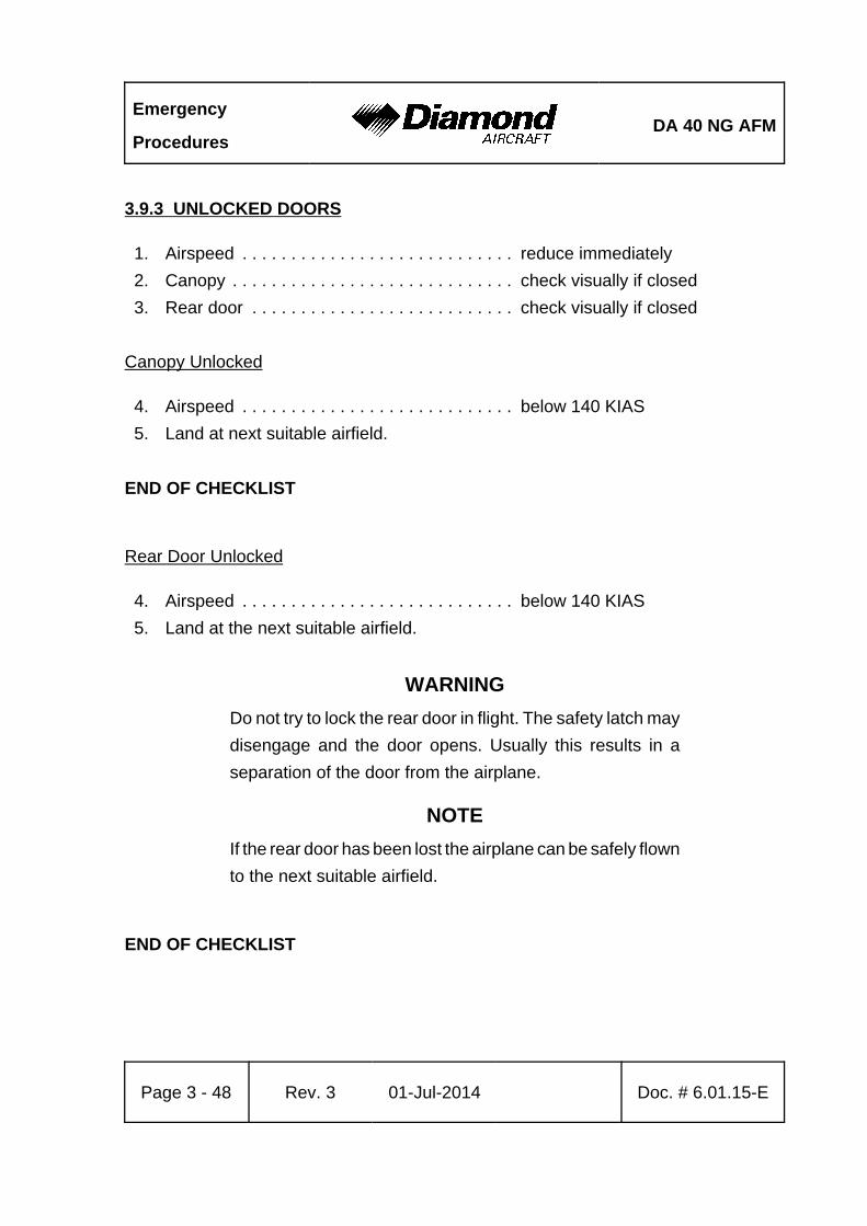
Emergency
ProceduresDA 40 NG AFM
Page 3 - 48 Rev. 3 01-Jul-2014 Doc. # 6.01.15-E
3.9.3 UNLOCKED DOORS
1. Airspeed . . . . . . . . . . . . . . . . . . . . . . . . . . . . reduce immediately
2. Canopy . . . . . . . . . . . . . . . . . . . . . . . . . . . . . check visually if closed
3. Rear door . . . . . . . . . . . . . . . . . . . . . . . . . . . check visually if closed
Canopy Unlocked
4. Airspeed . . . . . . . . . . . . . . . . . . . . . . . . . . . . below 140 KIAS
5. Land at next suitable airfield.
END OF CHECKLIST
Rear Door Unlocked
4. Airspeed . . . . . . . . . . . . . . . . . . . . . . . . . . . . below 140 KIAS
5. Land at the next suitable airfield.
WARNING
Do not try to lock the rear door in flight. The safety latch may
disengage and the door opens. Usually this results in a
separation of the door from the airplane.
NOTE
If the rear door has been lost the airplane can be safely flown
to the next suitable airfield.
END OF CHECKLIST

DA 40 NG AFMNormal Operating
Procedures
Doc. # 6.01.15-E Rev. 3 01-Jul-2014 Page 4A - 1
CHAPTER 4A
NORMAL OPERATING PROCEDURES
Page
4A.1 INTRODUCTION . . . . . . . . . . . . . . . . . . . . . . . . . . . . . . . . . . . . . . 4A-2
4A.2 AIRSPEEDS FOR NORMAL OPERATING PROCEDURES . . . . . 4A-2
4A.3 FLIGHT CHARACTERISTICS . . . . . . . . . . . . . . . . . . . . . . . . . . . . 4A-3
4A.4 DAILY CHECK . . . . . . . . . . . . . . . . . . . . . . . . . . . . . . . . . . . . . . . 4A-3
4A.5 CHECKLISTS FOR NORMAL OPERATING PROCEDURES . . . . 4A-4
4A.5.1 PRE-FLIGHT INSPECTION . . . . . . . . . . . . . . . . . . . . . . . 4A-4
4A.5.2 BEFORE STARTING ENGINE . . . . . . . . . . . . . . . . . . . . 4A-12
4A.5.3 STARTING ENGINE . . . . . . . . . . . . . . . . . . . . . . . . . . . . 4A-14
4A.5.4 BEFORE TAXIING . . . . . . . . . . . . . . . . . . . . . . . . . . . . . 4A-17
4A.5.5 TAXIING . . . . . . . . . . . . . . . . . . . . . . . . . . . . . . . . . . . . . 4A-19
4A.5.6 BEFORE TAKE-OFF . . . . . . . . . . . . . . . . . . . . . . . . . . . 4A-20
4A.5.7 TAKE-OFF . . . . . . . . . . . . . . . . . . . . . . . . . . . . . . . . . . . 4A-25
4A.5.8 CLIMB . . . . . . . . . . . . . . . . . . . . . . . . . . . . . . . . . . . . . . . 4A-27
4A.5.9 CRUISE . . . . . . . . . . . . . . . . . . . . . . . . . . . . . . . . . . . . . 4A-28
4A.5.10 FUEL TRANSFER . . . . . . . . . . . . . . . . . . . . . . . . . . . . 4A-29
4A.5.11 DESCENT . . . . . . . . . . . . . . . . . . . . . . . . . . . . . . . . . . 4A-30
4A.5.12 APPROACH & LANDING . . . . . . . . . . . . . . . . . . . . . . . 4A-31
4A.5.13 GO-AROUND . . . . . . . . . . . . . . . . . . . . . . . . . . . . . . . . 4A-33
4A.5.14 AFTER LANDING . . . . . . . . . . . . . . . . . . . . . . . . . . . . . 4A-34
4A.5.15 ENGINE SHUT-DOWN . . . . . . . . . . . . . . . . . . . . . . . . . 4A-35
4A.5.16 POST FLIGHT INSPECTION . . . . . . . . . . . . . . . . . . . . 4A-36
4A.5.17 PARKING . . . . . . . . . . . . . . . . . . . . . . . . . . . . . . . . . . . 4A-36
4A.5.18 FLIGHT IN RAIN . . . . . . . . . . . . . . . . . . . . . . . . . . . . . . 4A-37
4A.5.19 REFUELING . . . . . . . . . . . . . . . . . . . . . . . . . . . . . . . . . 4A-37
4A.5.20 FLIGHT AT HIGH ALTITUDE . . . . . . . . . . . . . . . . . . . . 4A-39
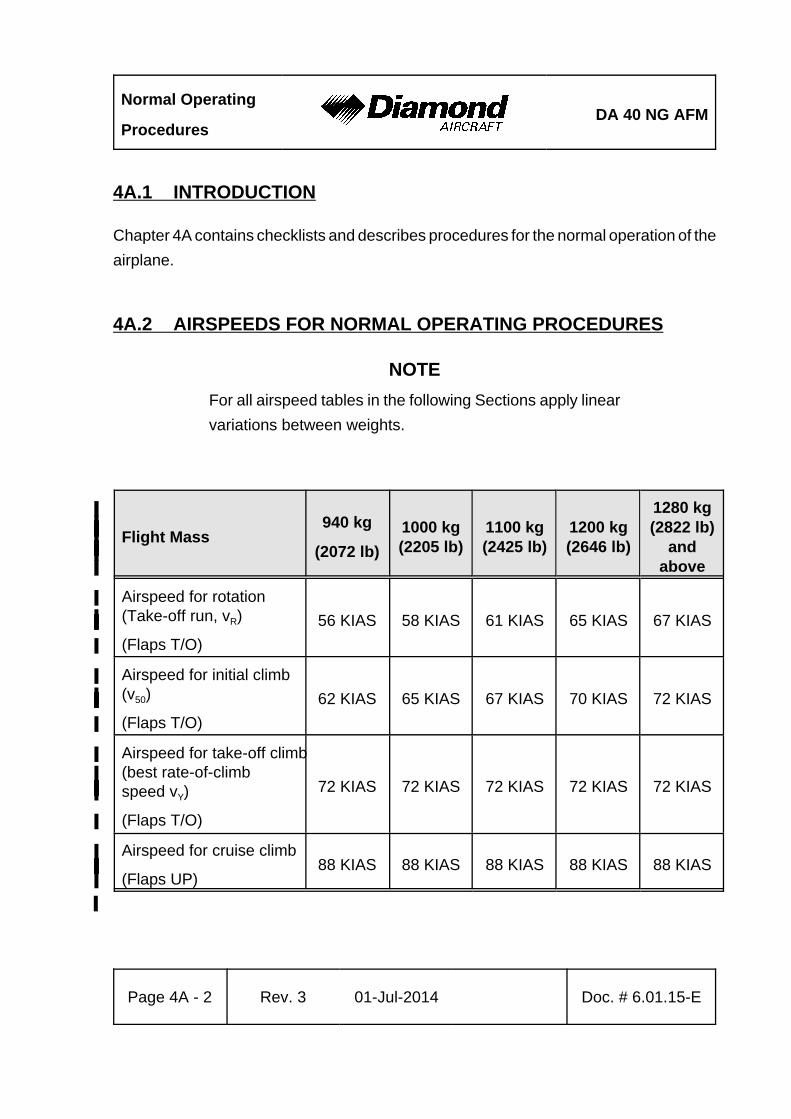
Normal Operating
ProceduresDA 40 NG AFM
Page 4A - 2 Rev. 3 01-Jul-2014 Doc. # 6.01.15-E
4A.1 INTRODUCTION
Chapter 4A contains checklists and describes procedures for the normal operation of the
airplane.
4A.2 AIRSPEEDS FOR NORMAL OPERATING PROCEDURES
NOTE
For all airspeed tables in the following Sections apply linear
variations between weights.
Flight Mass%940 kg%
(2072 lb)%
1000 kg%(2205 lb)%
1100 kg%(2425 lb)%
1200 kg%(2646 lb)%
1280 kg%(2822 lb)%
and%above%
Airspeed for rotation%(Take-off run, vR)%
(Flaps T/O)%
56 KIAS% 58 KIAS% 61 KIAS% 65 KIAS% 67 KIAS%
Airspeed for initial climb%(v50)%
(Flaps T/O)%
62 KIAS% 65 KIAS% 67 KIAS% 70 KIAS% 72 KIAS%
Airspeed for take-off climb%(best rate-of-climb%speed vY)%
(Flaps T/O)%
72 KIAS% 72 KIAS% 72 KIAS% 72 KIAS% 72 KIAS%
Airspeed for cruise climb%
(Flaps UP)%88 KIAS% 88 KIAS% 88 KIAS% 88 KIAS% 88 KIAS%
%
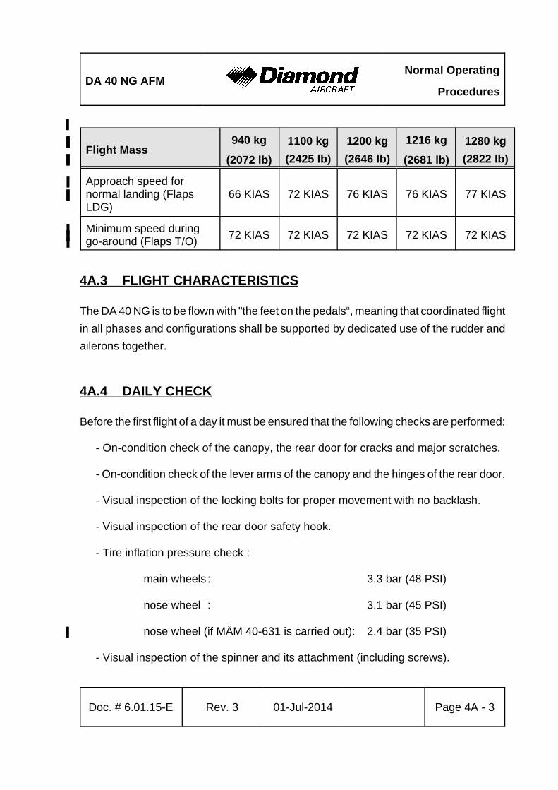
DA 40 NG AFMNormal Operating
Procedures
Doc. # 6.01.15-E Rev. 3 01-Jul-2014 Page 4A - 3
%
Flight Mass940 kg
(2072 lb)
1100 kg%
(2425 lb)%
1200 kg%
(2646 lb)%
1216 kg
(2681 lb)
1280 kg%
(2822 lb)%
Approach speed for%normal landing (Flaps%LDG)
66 KIAS 72 KIAS 76 KIAS% 76 KIAS 77 KIAS%
Minimum speed during%go-around (Flaps T/O)%
72 KIAS 72 KIAS 72 KIAS% 72 KIAS 72 KIAS%
4A.3 FLIGHT CHARACTERISTICS
The DA 40 NG is to be flown with "the feet on the pedals“, meaning that coordinated flight
in all phases and configurations shall be supported by dedicated use of the rudder and
ailerons together.
4A.4 DAILY CHECK
Before the first flight of a day it must be ensured that the following checks are performed:
- On-condition check of the canopy, the rear door for cracks and major scratches.
- On-condition check of the lever arms of the canopy and the hinges of the rear door.
- Visual inspection of the locking bolts for proper movement with no backlash.
- Visual inspection of the rear door safety hook.
- Tire inflation pressure check :
main wheels : 3.3 bar (48 PSI)
nose wheel : 3.1 bar (45 PSI)
nose wheel (if MÄM 40-631 is carried out): 2.4 bar (35 PSI)%
- Visual inspection of the spinner and its attachment (including screws).
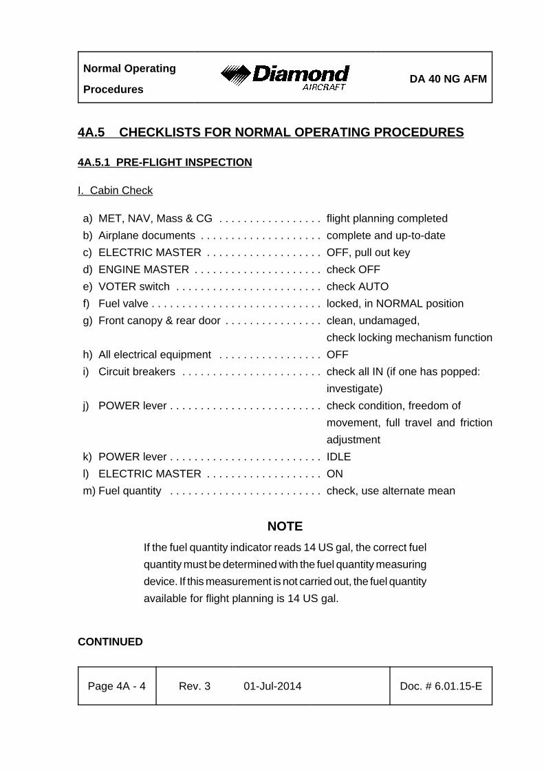
Normal Operating
ProceduresDA 40 NG AFM
Page 4A - 4 Rev. 3 01-Jul-2014 Doc. # 6.01.15-E
4A.5 CHECKLISTS FOR NORMAL OPERATING PROCEDURES
4A.5.1 PRE-FLIGHT INSPECTION
I. Cabin Check
a) MET, NAV, Mass & CG . . . . . . . . . . . . . . . . . flight planning completed
b) Airplane documents . . . . . . . . . . . . . . . . . . . . complete and up-to-date
c) ELECTRIC MASTER . . . . . . . . . . . . . . . . . . . OFF, pull out key
d) ENGINE MASTER . . . . . . . . . . . . . . . . . . . . . check OFF
e) VOTER switch . . . . . . . . . . . . . . . . . . . . . . . . check AUTO
f) Fuel valve . . . . . . . . . . . . . . . . . . . . . . . . . . . . locked, in NORMAL position
g) Front canopy & rear door . . . . . . . . . . . . . . . . clean, undamaged,
check locking mechanism function
h) All electrical equipment . . . . . . . . . . . . . . . . . OFF
i) Circuit breakers . . . . . . . . . . . . . . . . . . . . . . . check all IN (if one has popped:
investigate)
j) POWER lever . . . . . . . . . . . . . . . . . . . . . . . . . check condition, freedom of
movement, full travel and friction
adjustment
k) POWER lever . . . . . . . . . . . . . . . . . . . . . . . . . IDLE
l) ELECTRIC MASTER . . . . . . . . . . . . . . . . . . . ON
m) Fuel quantity . . . . . . . . . . . . . . . . . . . . . . . . . check, use alternate mean
NOTE
If the fuel quantity indicator reads 14 US gal, the correct fuel
quantity must be determined with the fuel quantity measuring
device. If this measurement is not carried out, the fuel quantity
available for flight planning is 14 US gal.
CONTINUED
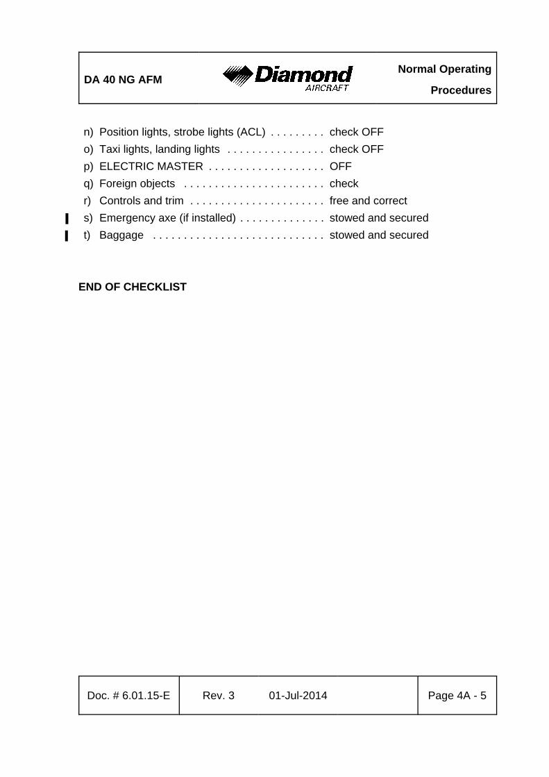
DA 40 NG AFMNormal Operating
Procedures
Doc. # 6.01.15-E Rev. 3 01-Jul-2014 Page 4A - 5
n) Position lights, strobe lights (ACL) . . . . . . . . . check OFF
o) Taxi lights, landing lights . . . . . . . . . . . . . . . . check OFF
p) ELECTRIC MASTER . . . . . . . . . . . . . . . . . . . OFF
q) Foreign objects . . . . . . . . . . . . . . . . . . . . . . . check
r) Controls and trim . . . . . . . . . . . . . . . . . . . . . . free and correct
s) Emergency axe (if installed) . . . . . . . . . . . . . . stowed and secured%
t) Baggage . . . . . . . . . . . . . . . . . . . . . . . . . . . . stowed and secured%
END OF CHECKLIST
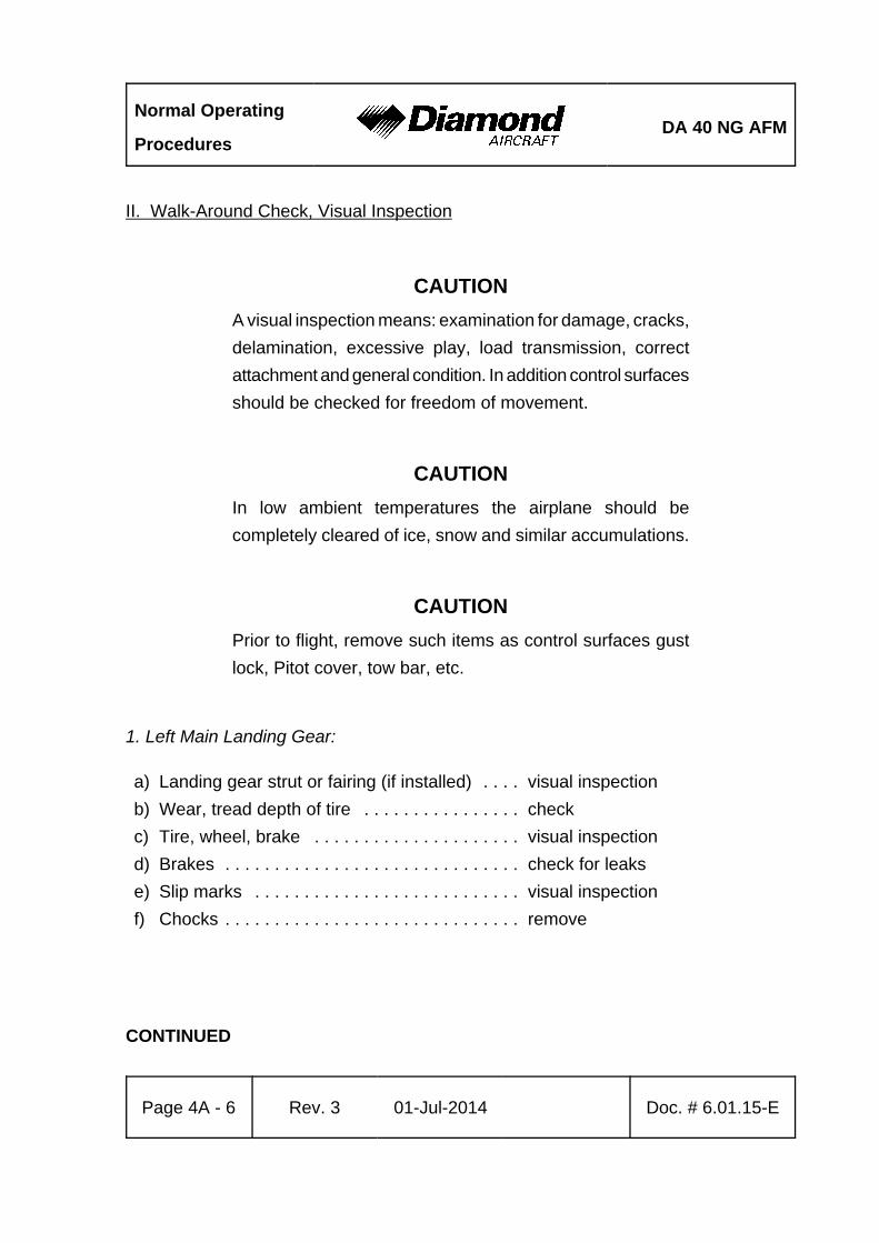
Normal Operating
ProceduresDA 40 NG AFM
Page 4A - 6 Rev. 3 01-Jul-2014 Doc. # 6.01.15-E
II. Walk-Around Check, Visual Inspection
CAUTION
A visual inspection means: examination for damage, cracks,
delamination, excessive play, load transmission, correct
attachment and general condition. In addition control surfaces
should be checked for freedom of movement.
CAUTION
In low ambient temperatures the airplane should be
completely cleared of ice, snow and similar accumulations.
CAUTION
Prior to flight, remove such items as control surfaces gust
lock, Pitot cover, tow bar, etc.
1. Left Main Landing Gear:
a) Landing gear strut or fairing (if installed) . . . . visual inspection
b) Wear, tread depth of tire . . . . . . . . . . . . . . . . check
c) Tire, wheel, brake . . . . . . . . . . . . . . . . . . . . . visual inspection
d) Brakes . . . . . . . . . . . . . . . . . . . . . . . . . . . . . . check for leaks
e) Slip marks . . . . . . . . . . . . . . . . . . . . . . . . . . . visual inspection
f) Chocks . . . . . . . . . . . . . . . . . . . . . . . . . . . . . . remove
CONTINUED
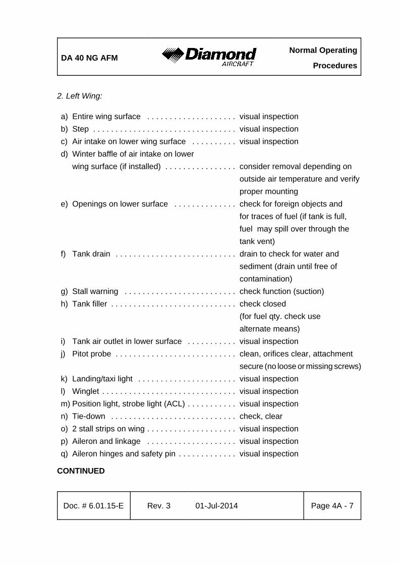
DA 40 NG AFMNormal Operating
Procedures
Doc. # 6.01.15-E Rev. 3 01-Jul-2014 Page 4A - 7
2. Left Wing:
a) Entire wing surface . . . . . . . . . . . . . . . . . . . . visual inspection
b) Step . . . . . . . . . . . . . . . . . . . . . . . . . . . . . . . . visual inspection
c) Air intake on lower wing surface . . . . . . . . . . visual inspection
d) Winter baffle of air intake on lower
wing surface (if installed) . . . . . . . . . . . . . . . . consider removal depending on
outside air temperature and verify
proper mounting
e) Openings on lower surface . . . . . . . . . . . . . . check for foreign objects and
for traces of fuel (if tank is full,
fuel may spill over through the
tank vent)
f) Tank drain . . . . . . . . . . . . . . . . . . . . . . . . . . . drain to check for water and
sediment (drain until free of
contamination)
g) Stall warning . . . . . . . . . . . . . . . . . . . . . . . . . check function (suction)
h) Tank filler . . . . . . . . . . . . . . . . . . . . . . . . . . . . check closed
(for fuel qty. check use
alternate means)
i) Tank air outlet in lower surface . . . . . . . . . . . visual inspection
j) Pitot probe . . . . . . . . . . . . . . . . . . . . . . . . . . . clean, orifices clear, attachment
secure (no loose or missing screws)
k) Landing/taxi light . . . . . . . . . . . . . . . . . . . . . . visual inspection
l) Winglet . . . . . . . . . . . . . . . . . . . . . . . . . . . . . . visual inspection
m) Position light, strobe light (ACL) . . . . . . . . . . . visual inspection
n) Tie-down . . . . . . . . . . . . . . . . . . . . . . . . . . . . check, clear
o) 2 stall strips on wing . . . . . . . . . . . . . . . . . . . . visual inspection
p) Aileron and linkage . . . . . . . . . . . . . . . . . . . . visual inspection
q) Aileron hinges and safety pin . . . . . . . . . . . . . visual inspection
CONTINUED
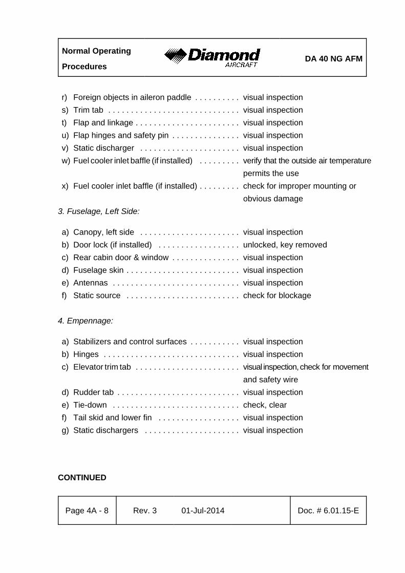
Normal Operating
ProceduresDA 40 NG AFM
Page 4A - 8 Rev. 3 01-Jul-2014 Doc. # 6.01.15-E
r) Foreign objects in aileron paddle . . . . . . . . . . visual inspection
s) Trim tab . . . . . . . . . . . . . . . . . . . . . . . . . . . . . visual inspection
t) Flap and linkage . . . . . . . . . . . . . . . . . . . . . . . visual inspection
u) Flap hinges and safety pin . . . . . . . . . . . . . . . visual inspection
v) Static discharger . . . . . . . . . . . . . . . . . . . . . . visual inspection
w) Fuel cooler inlet baffle (if installed) . . . . . . . . . verify that the outside air temperature
permits the use
x) Fuel cooler inlet baffle (if installed) . . . . . . . . . check for improper mounting or
obvious damage
3. Fuselage, Left Side:
a) Canopy, left side . . . . . . . . . . . . . . . . . . . . . . visual inspection
b) Door lock (if installed) . . . . . . . . . . . . . . . . . . unlocked, key removed
c) Rear cabin door & window . . . . . . . . . . . . . . . visual inspection
d) Fuselage skin . . . . . . . . . . . . . . . . . . . . . . . . . visual inspection
e) Antennas . . . . . . . . . . . . . . . . . . . . . . . . . . . . visual inspection
f) Static source . . . . . . . . . . . . . . . . . . . . . . . . . check for blockage
4. Empennage:
a) Stabilizers and control surfaces . . . . . . . . . . . visual inspection
b) Hinges . . . . . . . . . . . . . . . . . . . . . . . . . . . . . . visual inspection
c) Elevator trim tab . . . . . . . . . . . . . . . . . . . . . . . visual inspection, check for movement
and safety wire
d) Rudder tab . . . . . . . . . . . . . . . . . . . . . . . . . . . visual inspection
e) Tie-down . . . . . . . . . . . . . . . . . . . . . . . . . . . . check, clear
f) Tail skid and lower fin . . . . . . . . . . . . . . . . . . visual inspection
g) Static dischargers . . . . . . . . . . . . . . . . . . . . . visual inspection
CONTINUED
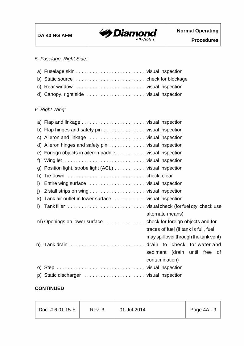
DA 40 NG AFMNormal Operating
Procedures
Doc. # 6.01.15-E Rev. 3 01-Jul-2014 Page 4A - 9
5. Fuselage, Right Side:
a) Fuselage skin . . . . . . . . . . . . . . . . . . . . . . . . . visual inspection
b) Static source . . . . . . . . . . . . . . . . . . . . . . . . . check for blockage
c) Rear window . . . . . . . . . . . . . . . . . . . . . . . . . visual inspection
d) Canopy, right side . . . . . . . . . . . . . . . . . . . . . visual inspection
6. Right Wing:
a) Flap and linkage . . . . . . . . . . . . . . . . . . . . . . . visual inspection
b) Flap hinges and safety pin . . . . . . . . . . . . . . . visual inspection
c) Aileron and linkage . . . . . . . . . . . . . . . . . . . . visual inspection
d) Aileron hinges and safety pin . . . . . . . . . . . . . visual inspection
e) Foreign objects in aileron paddle . . . . . . . . . . visual inspection
f) Wing let . . . . . . . . . . . . . . . . . . . . . . . . . . . . . visual inspection
g) Position light, strobe light (ACL) . . . . . . . . . . . visual inspection
h) Tie-down . . . . . . . . . . . . . . . . . . . . . . . . . . . . check, clear
i) Entire wing surface . . . . . . . . . . . . . . . . . . . . visual inspection
j) 2 stall strips on wing . . . . . . . . . . . . . . . . . . . . visual inspection
k) Tank air outlet in lower surface . . . . . . . . . . . visual inspection
l) Tank filler . . . . . . . . . . . . . . . . . . . . . . . . . . . . visual check (for fuel qty. check use
alternate means)
m) Openings on lower surface . . . . . . . . . . . . . . check for foreign objects and for
traces of fuel (if tank is full, fuel
may spill over through the tank vent)
n) Tank drain . . . . . . . . . . . . . . . . . . . . . . . . . . . drain to check for water and
sediment (drain until free of
contamination)
o) Step . . . . . . . . . . . . . . . . . . . . . . . . . . . . . . . . visual inspection
p) Static discharger . . . . . . . . . . . . . . . . . . . . . . visual inspection
CONTINUED
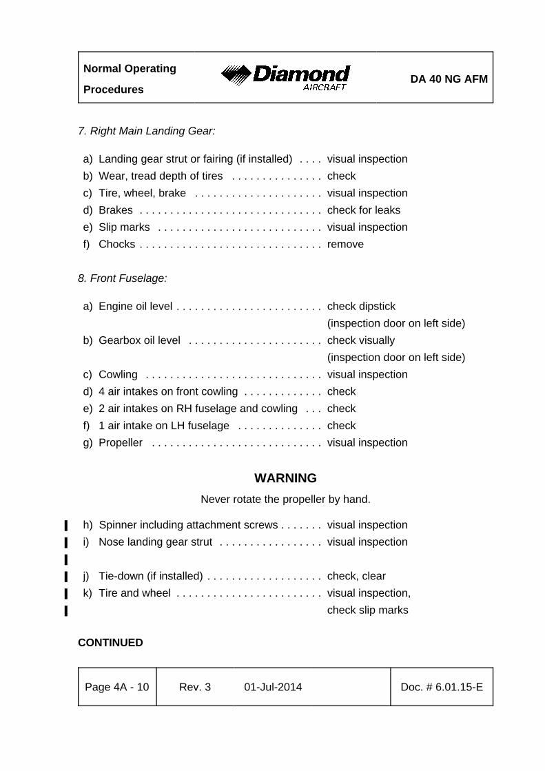
Normal Operating
ProceduresDA 40 NG AFM
Page 4A - 10 Rev. 3 01-Jul-2014 Doc. # 6.01.15-E
7. Right Main Landing Gear:
a) Landing gear strut or fairing (if installed) . . . . visual inspection
b) Wear, tread depth of tires . . . . . . . . . . . . . . . check
c) Tire, wheel, brake . . . . . . . . . . . . . . . . . . . . . visual inspection
d) Brakes . . . . . . . . . . . . . . . . . . . . . . . . . . . . . . check for leaks
e) Slip marks . . . . . . . . . . . . . . . . . . . . . . . . . . . visual inspection
f) Chocks . . . . . . . . . . . . . . . . . . . . . . . . . . . . . . remove
8. Front Fuselage:
a) Engine oil level . . . . . . . . . . . . . . . . . . . . . . . . check dipstick
(inspection door on left side)
b) Gearbox oil level . . . . . . . . . . . . . . . . . . . . . . check visually
(inspection door on left side)
c) Cowling . . . . . . . . . . . . . . . . . . . . . . . . . . . . . visual inspection
d) 4 air intakes on front cowling . . . . . . . . . . . . . check
e) 2 air intakes on RH fuselage and cowling . . . check
f) 1 air intake on LH fuselage . . . . . . . . . . . . . . check
g) Propeller . . . . . . . . . . . . . . . . . . . . . . . . . . . . visual inspection
WARNING
Never rotate the propeller by hand.
h) Spinner including attachment screws . . . . . . . visual inspection%
i) Nose landing gear strut . . . . . . . . . . . . . . . . . visual inspection%
%
j) Tie-down (if installed) . . . . . . . . . . . . . . . . . . . check, clear%
k) Tire and wheel . . . . . . . . . . . . . . . . . . . . . . . . visual inspection,%
check slip marks%
CONTINUED
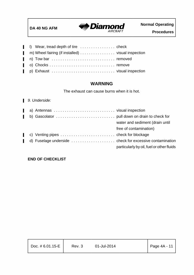
DA 40 NG AFMNormal Operating
Procedures
Doc. # 6.01.15-E Rev. 3 01-Jul-2014 Page 4A - 11
l) Wear, tread depth of tire . . . . . . . . . . . . . . . . check%
m) Wheel fairing (if installed) . . . . . . . . . . . . . . . . visual inspection%
n) Tow bar . . . . . . . . . . . . . . . . . . . . . . . . . . . . . removed%
o) Chocks . . . . . . . . . . . . . . . . . . . . . . . . . . . . . . remove%
p) Exhaust . . . . . . . . . . . . . . . . . . . . . . . . . . . . . visual inspection%
WARNING
The exhaust can cause burns when it is hot.
9. Underside:%
a) Antennas . . . . . . . . . . . . . . . . . . . . . . . . . . . . visual inspection%
b) Gascolator . . . . . . . . . . . . . . . . . . . . . . . . . . . pull down on drain to check for %
water and sediment (drain until
free of contamination)
c) Venting pipes . . . . . . . . . . . . . . . . . . . . . . . . . check for blockage%
d) Fuselage underside . . . . . . . . . . . . . . . . . . . . check for excessive contamination%
particularly by oil, fuel or other fluids
END OF CHECKLIST
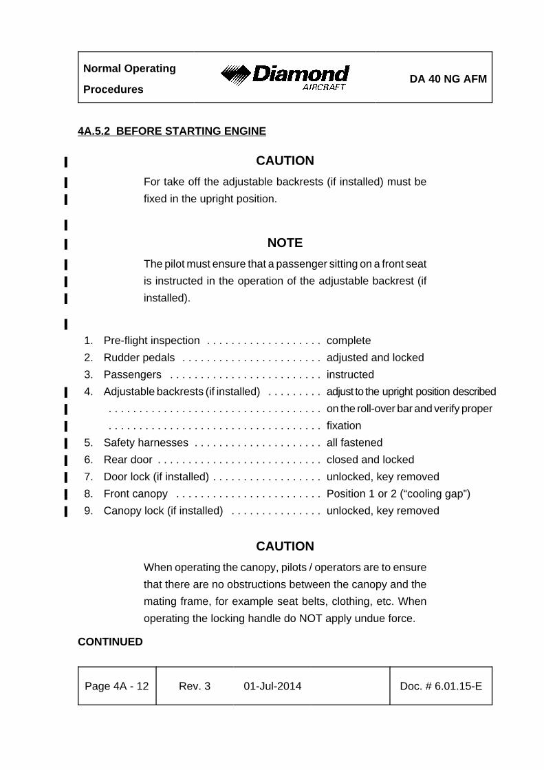
Normal Operating
ProceduresDA 40 NG AFM
Page 4A - 12 Rev. 3 01-Jul-2014 Doc. # 6.01.15-E
4A.5.2 BEFORE STARTING ENGINE
CAUTION%
For take off the adjustable backrests (if installed) must be%
fixed in the upright position.%
%
NOTE%
The pilot must ensure that a passenger sitting on a front seat%
is instructed in the operation of the adjustable backrest (if%
installed).%
%
1. Pre-flight inspection . . . . . . . . . . . . . . . . . . . complete
2. Rudder pedals . . . . . . . . . . . . . . . . . . . . . . . adjusted and locked
3. Passengers . . . . . . . . . . . . . . . . . . . . . . . . . instructed
4. Adjustable backrests (if installed) . . . . . . . . . adjust to the upright position described%
. . . . . . . . . . . . . . . . . . . . . . . . . . . . . . . . . . . on the roll-over bar and verify proper%
. . . . . . . . . . . . . . . . . . . . . . . . . . . . . . . . . . . fixation%
5. Safety harnesses . . . . . . . . . . . . . . . . . . . . . all fastened%
6. Rear door . . . . . . . . . . . . . . . . . . . . . . . . . . . closed and locked%
7. Door lock (if installed) . . . . . . . . . . . . . . . . . . unlocked, key removed%
8. Front canopy . . . . . . . . . . . . . . . . . . . . . . . . Position 1 or 2 (“cooling gap”)%
9. Canopy lock (if installed) . . . . . . . . . . . . . . . unlocked, key removed%
CAUTION
When operating the canopy, pilots / operators are to ensure
that there are no obstructions between the canopy and the
mating frame, for example seat belts, clothing, etc. When
operating the locking handle do NOT apply undue force.
CONTINUED
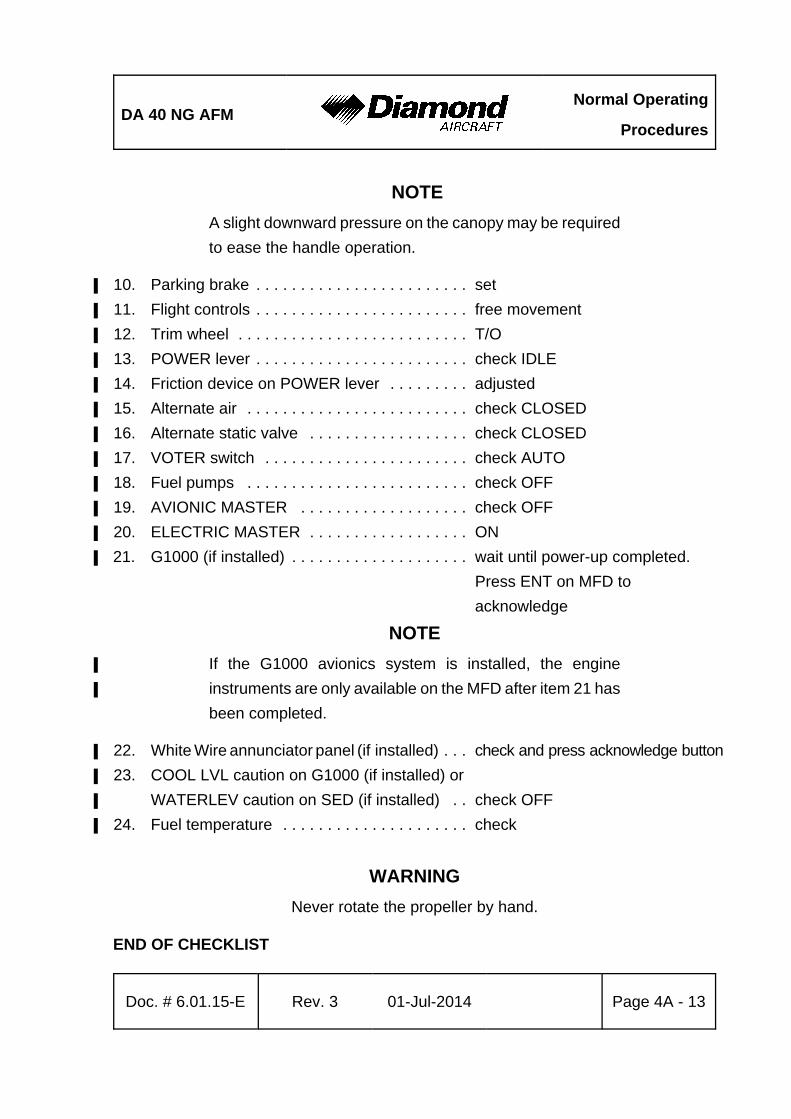
DA 40 NG AFMNormal Operating
Procedures
Doc. # 6.01.15-E Rev. 3 01-Jul-2014 Page 4A - 13
NOTE
A slight downward pressure on the canopy may be required
to ease the handle operation.
10. Parking brake . . . . . . . . . . . . . . . . . . . . . . . . set%
11. Flight controls . . . . . . . . . . . . . . . . . . . . . . . . free movement%
12. Trim wheel . . . . . . . . . . . . . . . . . . . . . . . . . . T/O%
13. POWER lever . . . . . . . . . . . . . . . . . . . . . . . . check IDLE%
14. Friction device on POWER lever . . . . . . . . . adjusted%
15. Alternate air . . . . . . . . . . . . . . . . . . . . . . . . . check CLOSED%
16. Alternate static valve . . . . . . . . . . . . . . . . . . check CLOSED%
17. VOTER switch . . . . . . . . . . . . . . . . . . . . . . . check AUTO%
18. Fuel pumps . . . . . . . . . . . . . . . . . . . . . . . . . check OFF%
19. AVIONIC MASTER . . . . . . . . . . . . . . . . . . . check OFF%
20. ELECTRIC MASTER . . . . . . . . . . . . . . . . . . ON%
21. G1000 (if installed) . . . . . . . . . . . . . . . . . . . . wait until power-up completed. %
Press ENT on MFD to
acknowledge
NOTE
If the G1000 avionics system is installed, the engine%
instruments are only available on the MFD after item 21 has%
been completed.
22. White Wire annunciator panel (if installed) . . . check and press acknowledge button%
23. COOL LVL caution on G1000 (if installed) or%
WATERLEV caution on SED (if installed) . . check OFF%
24. Fuel temperature . . . . . . . . . . . . . . . . . . . . . check%
WARNING
Never rotate the propeller by hand.
END OF CHECKLIST
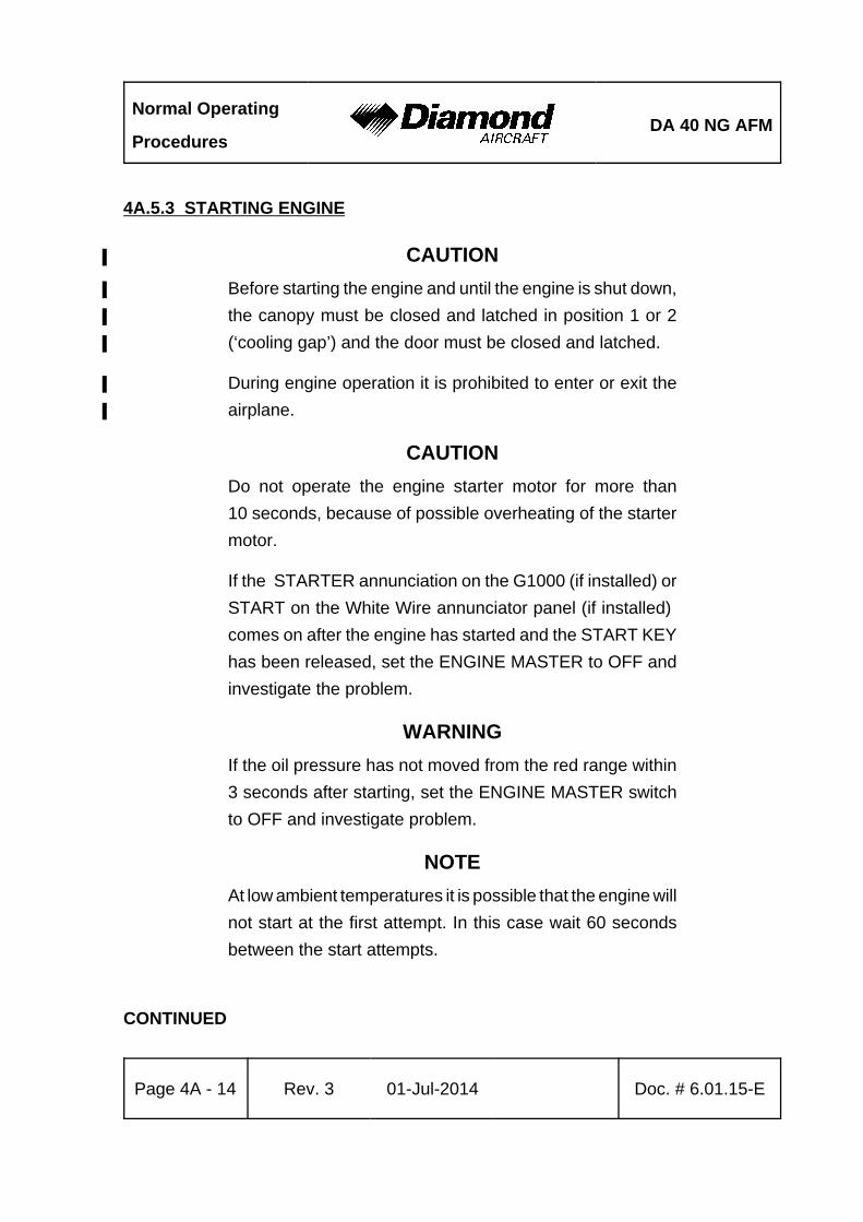
Normal Operating
ProceduresDA 40 NG AFM
Page 4A - 14 Rev. 3 01-Jul-2014 Doc. # 6.01.15-E
4A.5.3 STARTING ENGINE
CAUTION%
Before starting the engine and until the engine is shut down,%
the canopy must be closed and latched in position 1 or 2%
(‘cooling gap’) and the door must be closed and latched.%
During engine operation it is prohibited to enter or exit the%
airplane.%
CAUTION
Do not operate the engine starter motor for more than
10 seconds, because of possible overheating of the starter
motor.
If the STARTER annunciation on the G1000 (if installed) or
START on the White Wire annunciator panel (if installed)
comes on after the engine has started and the START KEY
has been released, set the ENGINE MASTER to OFF and
investigate the problem.
WARNING
If the oil pressure has not moved from the red range within
3 seconds after starting, set the ENGINE MASTER switch
to OFF and investigate problem.
NOTE
At low ambient temperatures it is possible that the engine will
not start at the first attempt. In this case wait 60 seconds
between the start attempts.
CONTINUED
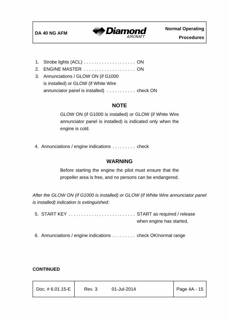
DA 40 NG AFMNormal Operating
Procedures
Doc. # 6.01.15-E Rev. 3 01-Jul-2014 Page 4A - 15
1. Strobe lights (ACL) . . . . . . . . . . . . . . . . . . . . ON
2. ENGINE MASTER . . . . . . . . . . . . . . . . . . . . ON
3. Annunciations / GLOW ON (if G1000
is installed) or GLOW (if White Wire
annunciator panel is installed) . . . . . . . . . . . check ON
NOTE
GLOW ON (if G1000 is installed) or GLOW (if White Wire
annunciator panel is installed) is indicated only when the
engine is cold.
4. Annunciations / engine indications . . . . . . . . . check
WARNING
Before starting the engine the pilot must ensure that the
propeller area is free, and no persons can be endangered.
After the GLOW ON (if G1000 is installed) or GLOW (if White Wire annunciator panel
is installed) indication is extinguished:
5. START KEY . . . . . . . . . . . . . . . . . . . . . . . . . . START as required / release
when engine has started.
6. Annunciations / engine indications . . . . . . . . . check OK/normal range
CONTINUED
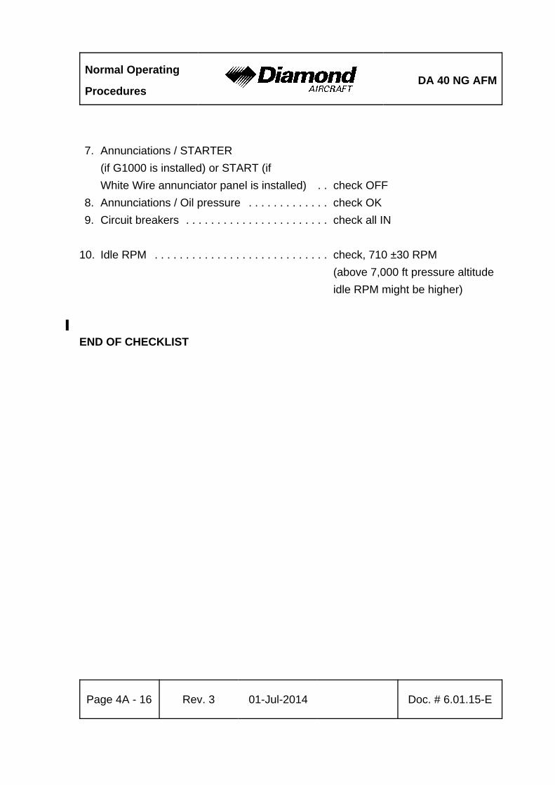
Normal Operating
ProceduresDA 40 NG AFM
Page 4A - 16 Rev. 3 01-Jul-2014 Doc. # 6.01.15-E
7. Annunciations / STARTER
(if G1000 is installed) or START (if
White Wire annunciator panel is installed) . . check OFF
8. Annunciations / Oil pressure . . . . . . . . . . . . . check OK
9. Circuit breakers . . . . . . . . . . . . . . . . . . . . . . . check all IN
10. Idle RPM . . . . . . . . . . . . . . . . . . . . . . . . . . . . check, 710 ±30 RPM
(above 7,000 ft pressure altitude
idle RPM might be higher)
%
END OF CHECKLIST
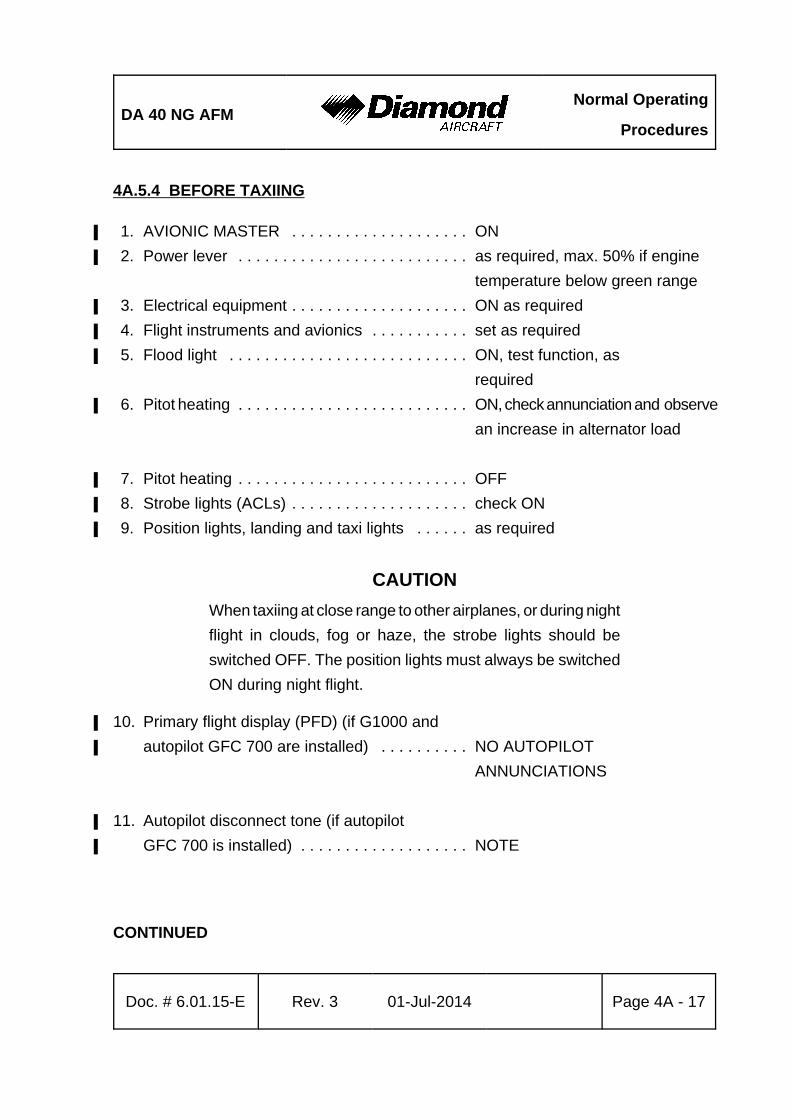
DA 40 NG AFMNormal Operating
Procedures
Doc. # 6.01.15-E Rev. 3 01-Jul-2014 Page 4A - 17
4A.5.4 BEFORE TAXIING
1. AVIONIC MASTER . . . . . . . . . . . . . . . . . . . . ON%
2. Power lever . . . . . . . . . . . . . . . . . . . . . . . . . . as required, max. 50% if engine %
temperature below green range
3. Electrical equipment . . . . . . . . . . . . . . . . . . . . ON as required%
4. Flight instruments and avionics . . . . . . . . . . . set as required%
5. Flood light . . . . . . . . . . . . . . . . . . . . . . . . . . . ON, test function, as%
required
6. Pitot heating . . . . . . . . . . . . . . . . . . . . . . . . . . ON, check annunciation and observe%
an increase in alternator load
7. Pitot heating . . . . . . . . . . . . . . . . . . . . . . . . . . OFF %
8. Strobe lights (ACLs) . . . . . . . . . . . . . . . . . . . . check ON%
9. Position lights, landing and taxi lights . . . . . . as required%
CAUTION
When taxiing at close range to other airplanes, or during night
flight in clouds, fog or haze, the strobe lights should be
switched OFF. The position lights must always be switched
ON during night flight.
10. Primary flight display (PFD) (if G1000 and%
autopilot GFC 700 are installed) . . . . . . . . . . NO AUTOPILOT%
ANNUNCIATIONS
11. Autopilot disconnect tone (if autopilot %
GFC 700 is installed) . . . . . . . . . . . . . . . . . . . NOTE %
CONTINUED

Normal Operating
ProceduresDA 40 NG AFM
Page 4A - 18 Rev. 3 01-Jul-2014 Doc. # 6.01.15-E
NOTE
If the G1000 avionics system and the autopilot GFC 700 are
installed, the AFCS automatically conducts a preflight self-test
upon initial power application. The preflight test is indicated
by a white boxed PFT on the PFD. Upon successful
completion of the preflight test, the PFT is removed, the red
AFCS annunciation is removed, and the autopilot disconnect
tone sounds. If AFCS annunciation remains on or a failure
of the preflight test is indicated terminate flight preparation
and investigate the problem.
12. MANUAL ELECTRIC TRIM - TEST as follows (if G1000 and autopilot GFC 700%
are installed): %
Press the AP DISC button down and hold while commanding trim.
Manual electric trim should not operate either nose up or nose down.
13. AUTOPILOT (if G1000 and autopilot %
GFC 700 are installed) . . . . . . . . . . . . . . . . . . engage by pressing AP button %
14. AP DISC switch (if G1000 and autopilot%
GFC 700 are installed) . . . . . . . . . . . . . . . . . . press. verify that the autopilot%
disconnects, check tone
15. TRIM . . . . . . . . . . . . . . . . . . . . . . . . . . . . . . . set to take-off position manually%
END OF CHECKLIST
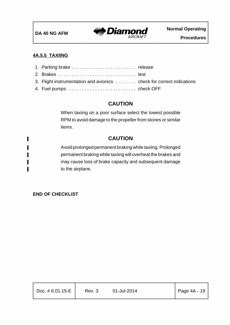
DA 40 NG AFMNormal Operating
Procedures
Doc. # 6.01.15-E Rev. 3 01-Jul-2014 Page 4A - 19
4A.5.5 TAXIING
1. Parking brake . . . . . . . . . . . . . . . . . . . . . . . . . release
2. Brakes . . . . . . . . . . . . . . . . . . . . . . . . . . . . . . test
3. Flight instrumentation and avionics . . . . . . . . check for correct indications
4. Fuel pumps . . . . . . . . . . . . . . . . . . . . . . . . . . check OFF
CAUTION
When taxiing on a poor surface select the lowest possible
RPM to avoid damage to the propeller from stones or similar
items.
CAUTION%
Avoid prolonged permanent braking while taxiing. Prolonged%
permanent braking while taxiing will overheat the brakes and%
may cause loss of brake capacity and subsequent damage%
to the airplane.%
END OF CHECKLIST
Normal Operating
ProceduresDA 40 NG AFM
Page 4A - 20 Rev. 3 01-Jul-2014 Doc. # 6.01.15-E
4A.5.6 BEFORE TAKE-OFF
CAUTION%
For take-off the adjustable backrests (if installed) must be%
fixed in the upright position.%
1. Position airplane into wind if possible.
2. Parking brake . . . . . . . . . . . . . . . . . . . . . . . . . set
3. Adjustable backrests (if installed) . . . . . . . . . . verify upright position %
and proper fixation%
4. Safety harnesses . . . . . . . . . . . . . . . . . . . . . . fastened%
5. Rear door . . . . . . . . . . . . . . . . . . . . . . . . . . . . check closed and locked%
CAUTION
When operating the canopy, pilots/operators must ensure that
there are no obstructions between the canopy and the mating
frame, for example seat belts, clothing, etc. When operating
the locking handle do NOT apply undue force.
A slight downward pressure on the canopy may be required
to ease the handle operation.
6. Front canopy . . . . . . . . . . . . . . . . . . . . . . . . . closed and locked%
7. Door warning (DOOR OPEN (if G1000 %
is installed) DOORS (if White Wire %
annunciator panel is installed) . . . . . . . . . . . . check no indication%
8. Annunciations / engine indications . . . . . . . . . check OK / normal range%
(except oil pressure may be in the
yellow range with a warm engine
and POWER lever set to IDLE)
9. Circuit breakers . . . . . . . . . . . . . . . . . . . . . . . check pressed in%
10.Longitudinal trim . . . . . . . . . . . . . . . . . . . . . . . set T/O%
DA 40 NG AFMNormal Operating
Procedures
Doc. # 6.01.15-E Rev. 3 01-Jul-2014 Page 4A - 21
11. Fuel valve . . . . . . . . . . . . . . . . . . . . . . . . . . . . check NORMAL%
12. FLAPS . . . . . . . . . . . . . . . . . . . . . . . . . . . . . . check function & indicator /%
set T/O
13. Flight controls . . . . . . . . . . . . . . . . . . . . . . . . . unrestricted free movement,%
correct sense
14. Pitot heating . . . . . . . . . . . . . . . . . . . . . . . . . . ON, if required%
15. Landing light . . . . . . . . . . . . . . . . . . . . . . . . . . ON, if required%
ECU / Fuel Pump Test Sequence:
CAUTION
If the ECU A/B FAIL (if G1000 is installed) or ECU A/B (if
White Wire annunciator panel is installed) indicators do not
illuminate during the test sequence there is a malfunction in
the engine control system. Terminate flight preparation.
The whole test procedure must be completed without any
error (ECU A/B FAIL (if G1000 is installed) or ECU A/B (if
White Wire annunciator panel is installed) extinguished after
test completion). In case the test procedure aborts with an
error indication (one or both ECU A/B FAIL (if G1000 is
installed) or ECU A/B (if White Wire annunciator panel is
installed) indicators remain ON) terminate flight preparation,
even if the engine seems to run smoothly after the test
procedure.
CAUTION
During the test sequence the engine will produce thrust
therefore the parking brake must be set.
CONTINUED
Normal Operating
ProceduresDA 40 NG AFM
Page 4A - 22 Rev. 3 01-Jul-2014 Doc. # 6.01.15-E
NOTE
The engine oil / gearbox temperature has to be in the green%
range before starting the test sequence. Efficient engine warm%
up may require higher power settings (max. 50% engine%
power). Releasing the ECU TEST BUTTON or manipulating%
the POWER lever before the test sequence is completed will
abort the test sequence. During the following ECU and fuel
pump test, a shake of the engine might occur.
1. POWER lever . . . . . . . . . . . . . . . . . . . . . . . . . IDLE
2. Propeller RPM . . . . . . . . . . . . . . . . . . . . . . . . check below 1000 RPM
3. Fuel pumps . . . . . . . . . . . . . . . . . . . . . . . . . . check OFF
4. VOTER switch . . . . . . . . . . . . . . . . . . . . . . . . check AUTO
NOTE
If the VOTER switch is not in the AUTO position, the ECU
test will not start.
5. All engine temperatures . . . . . . . . . . . . . . . . . check in the green range
6. Parking brake . . . . . . . . . . . . . . . . . . . . . . . . . check set
7. ECU TEST button . . . . . . . . . . . . . . . . . . . . . press and hold
NOTE
The ECU test consists of the following sequence: the propeller
RPM will increase to above 1900 RPM. This is followed by
a slight RPM drop, than a recovery before returning to idle
RPM. At this point the ECU switches back to the other ECU
channel and the sequence is repeated. At the end of the test,
the control of the engine is returned to the initially active ECU
channel. A slight shake of the engine may occur during ECU
switching.
CONTINUED
DA 40 NG AFMNormal Operating
Procedures
Doc. # 6.01.15-E Rev. 3 01-Jul-2014 Page 4A - 23
8. ECU A/B FAIL (if G1000 is installed) or
ECU A/B (if White Wire annunciator
panel is installed) lights . . . . . . . . . . . . . . . . . verify both OFF
Test sequence completed.
9. ECU TEST button . . . . . . . . . . . . . . . . . . . . . release
NOTE
By switching between ECU A and B the two independent
electrical fuel pumps are switched over as well.
10.VOTER switch . . . . . . . . . . . . . . . . . . . . . . . . ECU A
11.Engine . . . . . . . . . . . . . . . . . . . . . . . . . . . . . . check running without a change
(shake may occur)
12.VOTER switch . . . . . . . . . . . . . . . . . . . . . . . . AUTO
13.Engine . . . . . . . . . . . . . . . . . . . . . . . . . . . . . . check running without a change
(shake may occur)
14.VOTER switch . . . . . . . . . . . . . . . . . . . . . . . . ECU B
15.Engine . . . . . . . . . . . . . . . . . . . . . . . . . . . . . . check running without a change
(shake may occur)
16.VOTER switch . . . . . . . . . . . . . . . . . . . . . . . . AUTO
CAUTION
Running the engine with the VOTER switch on ECU A or
ECU B, other than for this test or in an emergency is
prohibited. The engine control system redundancy is only
given with the VOTER switch set to AUTO.
CONTINUED
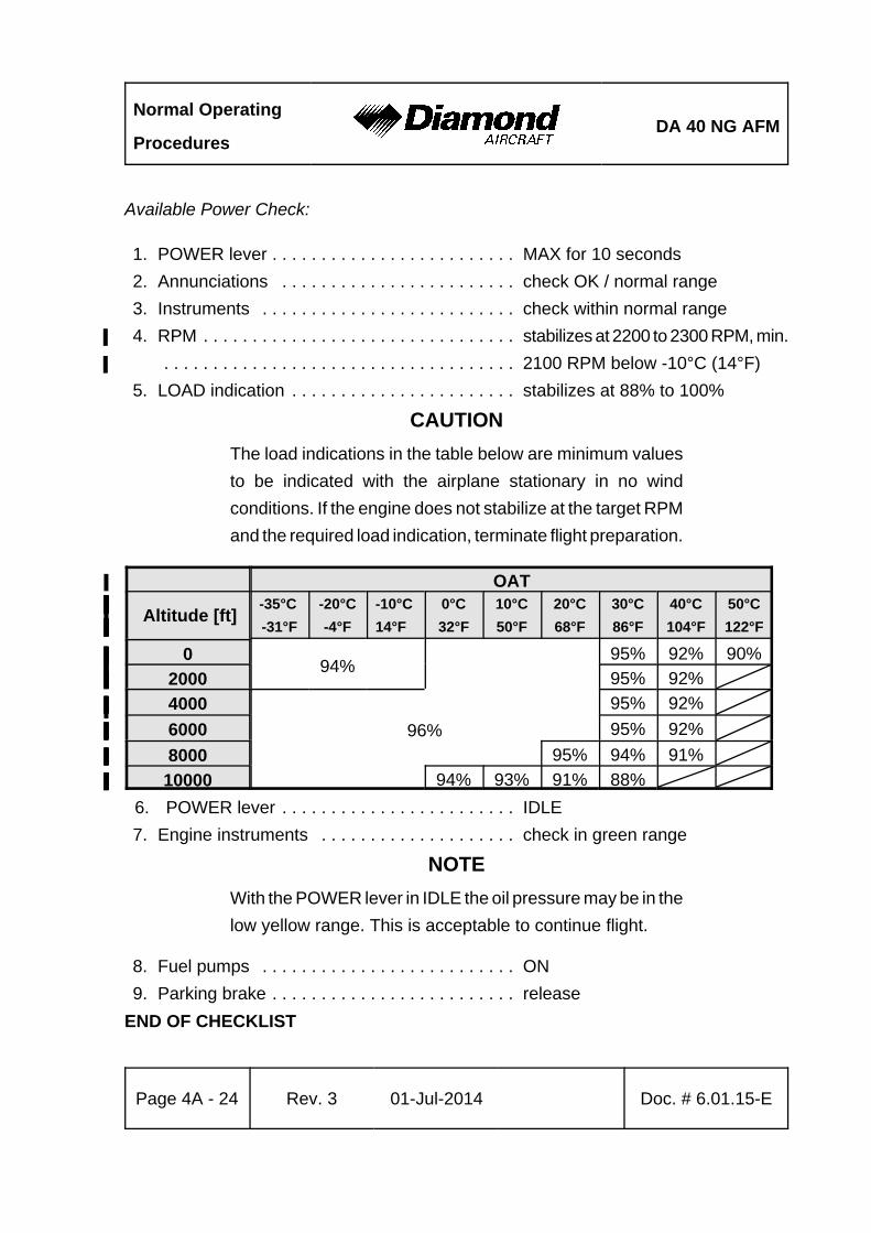
Normal Operating
ProceduresDA 40 NG AFM
Page 4A - 24 Rev. 3 01-Jul-2014 Doc. # 6.01.15-E
Available Power Check:
1. POWER lever . . . . . . . . . . . . . . . . . . . . . . . . . MAX for 10 seconds
2. Annunciations . . . . . . . . . . . . . . . . . . . . . . . . check OK / normal range
3. Instruments . . . . . . . . . . . . . . . . . . . . . . . . . . check within normal range
4. RPM . . . . . . . . . . . . . . . . . . . . . . . . . . . . . . . . stabilizes at 2200 to 2300 RPM, min.%
. . . . . . . . . . . . . . . . . . . . . . . . . . . . . . . . . . . . 2100 RPM below -10°C (14°F)%
5. LOAD indication . . . . . . . . . . . . . . . . . . . . . . . stabilizes at 88% to 100%
CAUTION
The load indications in the table below are minimum values
to be indicated with the airplane stationary in no wind
conditions. If the engine does not stabilize at the target RPM
and the required load indication, terminate flight preparation.
OAT%
Altitude [ft]%-35°C %
-31°F%
-20°C%
-4°F%
-10°C%
14°F%
0°C%
32°F%
10°C%
50°F%
20°C%
68°F%
30°C%
86°F%
40°C%
104°F%
50°C%
122°F%
0%%94%%
%%
95%% 92%% 90%%
2000%%%%% 95%% 92%%%
4000%%
96%%
95%% 92%%%
6000%%
95%% 92%%%
8000%% 95%% 94%% 91%%%
10000%% 94%% 93%% 91%% 88%%%%
6. POWER lever . . . . . . . . . . . . . . . . . . . . . . . . IDLE
7. Engine instruments . . . . . . . . . . . . . . . . . . . . check in green range
NOTE
With the POWER lever in IDLE the oil pressure may be in the
low yellow range. This is acceptable to continue flight.
8. Fuel pumps . . . . . . . . . . . . . . . . . . . . . . . . . . ON
9. Parking brake . . . . . . . . . . . . . . . . . . . . . . . . . release
END OF CHECKLIST
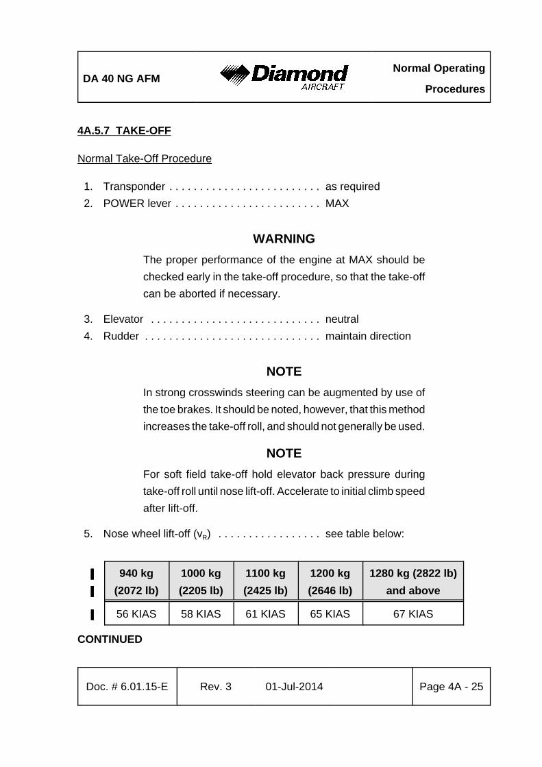
DA 40 NG AFMNormal Operating
Procedures
Doc. # 6.01.15-E Rev. 3 01-Jul-2014 Page 4A - 25
4A.5.7 TAKE-OFF
Normal Take-Off Procedure
1. Transponder . . . . . . . . . . . . . . . . . . . . . . . . . as required
2. POWER lever . . . . . . . . . . . . . . . . . . . . . . . . MAX
WARNING
The proper performance of the engine at MAX should be
checked early in the take-off procedure, so that the take-off
can be aborted if necessary.
3. Elevator . . . . . . . . . . . . . . . . . . . . . . . . . . . . neutral
4. Rudder . . . . . . . . . . . . . . . . . . . . . . . . . . . . . maintain direction
NOTE
In strong crosswinds steering can be augmented by use of
the toe brakes. It should be noted, however, that this method
increases the take-off roll, and should not generally be used.
NOTE
For soft field take-off hold elevator back pressure during
take-off roll until nose lift-off. Accelerate to initial climb speed
after lift-off.
5. Nose wheel lift-off (vR) . . . . . . . . . . . . . . . . . see table below:
940 kg
(2072 lb)
1000 kg
(2205 lb)
1100 kg
(2425 lb)
1200 kg%
(2646 lb)%
1280 kg (2822 lb)%
and above%
56 KIAS 58 KIAS 61 KIAS 65 KIAS% 67 KIAS%
CONTINUED

Normal Operating
ProceduresDA 40 NG AFM
Page 4A - 26 Rev. 3 01-Jul-2014 Doc. # 6.01.15-E
NOTE
A spurious activation of the stall warning during take-off in
crosswind conditions, operation on unpaved surfaces and
gusty conditions may occur.
6. Airspeed for initial climb . . . . . . . . . . . . . . . . . see table below:
940 kg
(2072 lb)
1000 kg
(2205 lb)
1100 kg
(2425 lb)
1200 kg
(2646 lb)
1280 kg (2822 lb)%
and above%
62 KIAS 65 KIAS 67 KIAS 70 KIAS 72 KIAS
Above a Safe Height:
7. Landing light . . . . . . . . . . . . . . . . . . . . . . . . . OFF
8. Fuel pumps . . . . . . . . . . . . . . . . . . . . . . . . . OFF
9. POWER lever . . . . . . . . . . . . . . . . . . . . . . . . reduce to 92% load
END OF CHECKLIST
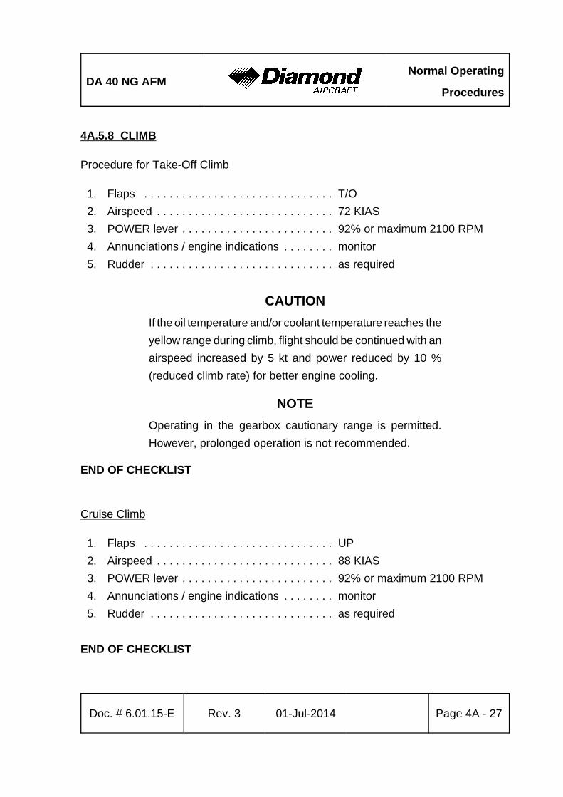
DA 40 NG AFMNormal Operating
Procedures
Doc. # 6.01.15-E Rev. 3 01-Jul-2014 Page 4A - 27
4A.5.8 CLIMB
Procedure for Take-Off Climb
1. Flaps . . . . . . . . . . . . . . . . . . . . . . . . . . . . . . T/O
2. Airspeed . . . . . . . . . . . . . . . . . . . . . . . . . . . . 72 KIAS
3. POWER lever . . . . . . . . . . . . . . . . . . . . . . . . 92% or maximum 2100 RPM
4. Annunciations / engine indications . . . . . . . . monitor
5. Rudder . . . . . . . . . . . . . . . . . . . . . . . . . . . . . as required
CAUTION
If the oil temperature and/or coolant temperature reaches the
yellow range during climb, flight should be continued with an
airspeed increased by 5 kt and power reduced by 10 %
(reduced climb rate) for better engine cooling.
NOTE
Operating in the gearbox cautionary range is permitted.
However, prolonged operation is not recommended.
END OF CHECKLIST
Cruise Climb
1. Flaps . . . . . . . . . . . . . . . . . . . . . . . . . . . . . . UP
2. Airspeed . . . . . . . . . . . . . . . . . . . . . . . . . . . . 88 KIAS
3. POWER lever . . . . . . . . . . . . . . . . . . . . . . . . 92% or maximum 2100 RPM
4. Annunciations / engine indications . . . . . . . . monitor
5. Rudder . . . . . . . . . . . . . . . . . . . . . . . . . . . . . as required
END OF CHECKLIST

Normal Operating
ProceduresDA 40 NG AFM
Page 4A - 28 Rev. 3 01-Jul-2014 Doc. # 6.01.15-E
4A.5.9 CRUISE
1. Flaps . . . . . . . . . . . . . . . . . . . . . . . . . . . . . . UP
2. POWER lever . . . . . . . . . . . . . . . . . . . . . . . . up to 92% or maximum 2100 RPM
3. Trim . . . . . . . . . . . . . . . . . . . . . . . . . . . . . . . as required
4. Fuel transfer . . . . . . . . . . . . . . . . . . . . . . . . . repeat as required (in accordance
with 4A.5.10 - FUEL TRANSFER)
NOTE
The engine manufacturer recommends a cruise power setting
of 75 %.
NOTE
Proper operation of the transfer pump must be checked by
monitoring the fuel quantities (increasing in the MAIN tank,
decreasing in the AUX tank, approx. 1 US gal per minute).
END OF CHECKLIST
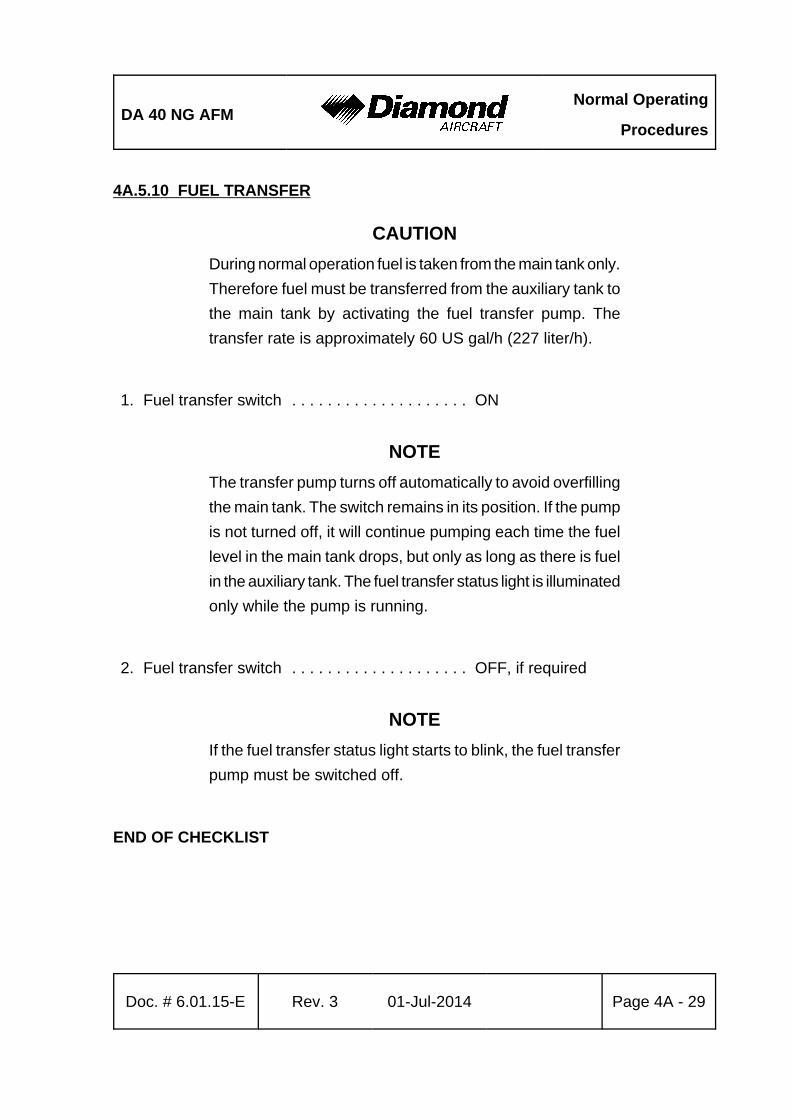
DA 40 NG AFMNormal Operating
Procedures
Doc. # 6.01.15-E Rev. 3 01-Jul-2014 Page 4A - 29
4A.5.10 FUEL TRANSFER
CAUTION
During normal operation fuel is taken from the main tank only.
Therefore fuel must be transferred from the auxiliary tank to
the main tank by activating the fuel transfer pump. The
transfer rate is approximately 60 US gal/h (227 liter/h).
1. Fuel transfer switch . . . . . . . . . . . . . . . . . . . . ON
NOTE
The transfer pump turns off automatically to avoid overfilling
the main tank. The switch remains in its position. If the pump
is not turned off, it will continue pumping each time the fuel
level in the main tank drops, but only as long as there is fuel
in the auxiliary tank. The fuel transfer status light is illuminated
only while the pump is running.
2. Fuel transfer switch . . . . . . . . . . . . . . . . . . . . OFF, if required
NOTE
If the fuel transfer status light starts to blink, the fuel transfer
pump must be switched off.
END OF CHECKLIST

Normal Operating
ProceduresDA 40 NG AFM
Page 4A - 30 Rev. 3 01-Jul-2014 Doc. # 6.01.15-E
4A.5.11 DESCENT
1. POWER lever . . . . . . . . . . . . . . . . . . . . . . . . as required
2. Airspeed . . . . . . . . . . . . . . . . . . . . . . . . . . . as required
3. Trim . . . . . . . . . . . . . . . . . . . . . . . . . . . . . . . as required
4. Annunciations / engine indications . . . . . . . . monitor
END OF CHECKLIST

DA 40 NG AFMNormal Operating
Procedures
Doc. # 6.01.15-E Rev. 3 01-Jul-2014 Page 4A - 31
4A.5.12 APPROACH & LANDING
Approach:
NOTE
If MÄM 40-574 is NOT carried out, a landing with a mass%
between 1216 kg (2681 lb) and 1280 kg (2822 lb) constitutes%
an abnormal operating procedure. Refer to Section 4B.7 -
LANDING WITH HIGH LANDING MASS.
CAUTION%
For landing the adjustable backrests (if installed) must be%
fixed in the upright position.%
1. Adjustable backrests (if installed) . . . . . . . . . . adjust to the upright %
position described by a placard%
on the roll-over bar and verify%
proper fixation%
2. Safety harnesses . . . . . . . . . . . . . . . . . . . . . . check fastened and tightened%
3. Controls . . . . . . . . . . . . . . . . . . . . . . . . . . . . . no interference by foreign objects%
4. Landing light . . . . . . . . . . . . . . . . . . . . . . . . . . as required%
5. Fuel pumps . . . . . . . . . . . . . . . . . . . . . . . . . . ON%
6. Parking brake . . . . . . . . . . . . . . . . . . . . . . . . . check released%
7. Trim . . . . . . . . . . . . . . . . . . . . . . . . . . . . . . . . as required%
CONTINUED
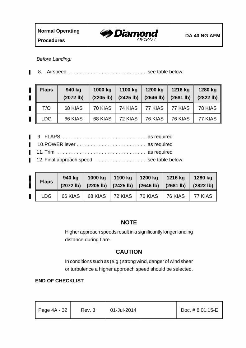
Normal Operating
ProceduresDA 40 NG AFM
Page 4A - 32 Rev. 3 01-Jul-2014 Doc. # 6.01.15-E
Before Landing:
8. Airspeed . . . . . . . . . . . . . . . . . . . . . . . . . . . . see table below:%
Flaps% 940 kg
(2072 lb)
1000 kg
(2205 lb)
1100 kg%
(2425 lb)%
1200 kg%
(2646 lb)%
1216 kg
(2681 lb)
1280 kg%
(2822 lb)%
T/O% 68 KIAS 70 KIAS 74 KIAS% 77 KIAS% 77 KIAS 78 KIAS%
LDG% 66 KIAS 68 KIAS% 72 KIAS% 76 KIAS% 76 KIAS 77 KIAS%
9. FLAPS . . . . . . . . . . . . . . . . . . . . . . . . . . . . . . as required%
10.POWER lever . . . . . . . . . . . . . . . . . . . . . . . . . as required%
11. Trim . . . . . . . . . . . . . . . . . . . . . . . . . . . . . . . . as required%
12. Final approach speed . . . . . . . . . . . . . . . . . . see table below:%
Flaps%940 kg
(2072 lb)
1000 kg
(2205 lb)
1100 kg%
(2425 lb)%
1200 kg%
(2646 lb)%
1216 kg
(2681 lb)
1280 kg%
(2822 lb)%
LDG% 66 KIAS 68 KIAS% 72 KIAS 76 KIAS% 76 KIAS 77 KIAS%
NOTE
Higher approach speeds result in a significantly longer landing
distance during flare.
CAUTION
In conditions such as (e.g.) strong wind, danger of wind shear
or turbulence a higher approach speed should be selected.
END OF CHECKLIST
DA 40 NG AFMNormal Operating
Procedures
Doc. # 6.01.15-E Rev. 3 01-Jul-2014 Page 4A - 33
4A.5.13 GO-AROUND
1. POWER lever . . . . . . . . . . . . . . . . . . . . . . . . MAX
2. Airspeed . . . . . . . . . . . . . . . . . . . . . . . . . . . . 72 KIAS
3. Flaps . . . . . . . . . . . . . . . . . . . . . . . . . . . . . . T/O
Above a Safe Height:
4. Airspeed . . . . . . . . . . . . . . . . . . . . . . . . . . . . 88 KIAS
5. Flaps . . . . . . . . . . . . . . . . . . . . . . . . . . . . . . UP
END OF CHECKLIST
Normal Operating
ProceduresDA 40 NG AFM
Page 4A - 34 Rev. 3 01-Jul-2014 Doc. # 6.01.15-E
4A.5.14 AFTER LANDING
1. POWER lever . . . . . . . . . . . . . . . . . . . . . . . . IDLE
2. Brakes . . . . . . . . . . . . . . . . . . . . . . . . . . . . . as required
3. Transponder . . . . . . . . . . . . . . . . . . . . . . . . . OFF / STBY
4. Pitot heating . . . . . . . . . . . . . . . . . . . . . . . . . OFF
5. Avionics . . . . . . . . . . . . . . . . . . . . . . . . . . . . as required
6. Lights . . . . . . . . . . . . . . . . . . . . . . . . . . . . . . as required
7. Flaps . . . . . . . . . . . . . . . . . . . . . . . . . . . . . . UP
8. Fuel pumps . . . . . . . . . . . . . . . . . . . . . . . . . OFF
END OF CHECKLIST
DA 40 NG AFMNormal Operating
Procedures
Doc. # 6.01.15-E Rev. 3 01-Jul-2014 Page 4A - 35
4A.5.15 ENGINE SHUT-DOWN
1. Parking brake . . . . . . . . . . . . . . . . . . . . . . . . . set
2. POWER lever . . . . . . . . . . . . . . . . . . . . . . . . . up to 10 % load for 1 minute
3. Engine indications . . . . . . . . . . . . . . . . . . . . . check %
4. ELT . . . . . . . . . . . . . . . . . . . . . . . . . . . . . . . . check not transmitting on
121.5 MHz
5. AVIONIC MASTER . . . . . . . . . . . . . . . . . . . . OFF
6. Electrical consumers . . . . . . . . . . . . . . . . . . . OFF
7. ENGINE MASTER . . . . . . . . . . . . . . . . . . . . . OFF
8. Strobe . . . . . . . . . . . . . . . . . . . . . . . . . . . . . . OFF
CAUTION
After turning the ENGINE MASTER OFF, wait until the engine
indications on the G1000 MFD (if installed) or MED (if%
installed) disappear prior to switching the ELECTRIC%
MASTER OFF. This ensures that engine and flight data can
be written to non-volatile memory before removing electrical
power.
9. ELECTRIC MASTER . . . . . . . . . . . . . . . . . . . OFF
CAUTION
Do not shut down an engine by placing the FUEL VALVE in
the OFF position. The high pressure fuel pump can otherwise
be damaged.
NOTE
Before shut-down the engine must run for at least 1 minute
with the POWER lever set up to 10% load to avoid heat
damage of the turbo charger.
END OF CHECKLIST
Normal Operating
ProceduresDA 40 NG AFM
Page 4A - 36 Rev. 3 01-Jul-2014 Doc. # 6.01.15-E
4A.5.16 POST FLIGHT INSPECTION
1. Record any problem found in flight and during the post-flight check in the log book.
2. Park the airplane.
3. If necessary, moor the airplane.
END OF CHECKLIST
4A.5.17 PARKING
1. Parking brake . . . . . . . . . . . . . . . . . . . . . . . . . release, use chocks
2. Airplane . . . . . . . . . . . . . . . . . . . . . . . . . . . . . moor, if unsupervised for
extended period
3. Pitot probe . . . . . . . . . . . . . . . . . . . . . . . . . . . cover
END OF CHECKLIST
DA 40 NG AFMNormal Operating
Procedures
Doc. # 6.01.15-E Rev. 3 01-Jul-2014 Page 4A - 37
4A.5.18 FLIGHT IN RAIN
NOTE
Performance deteriorates in rain; this applies particularly to
the take-off distance and to the maximum horizontal speed.
The effect on the flight characteristics is minimal. Flight
through very heavy rain should be avoided because of the
associated visibility problems.
4A.5.19 REFUELING
CAUTION
Before refueling, the airplane must be connected to electrical
ground. Grounding points: unpainted areas on steps, left and
right.
Use of Fuel Additives%
CAUTION%
Only approved fuel additives not exceeding the approved%
concentrations may be used; refer to Section 2.14 FUEL. The%
instructions of the fuel additive supplier must be followed.%
Failure to exactly follow the fuel additive mixing procedures%
during refueling can result in incorrect fuel additive%
concentrations, fuel system contamination and possible%
engine stoppage.%
Fuel additives may have been already mixed into the fuel when stored. In this case make%
sure that the brand is approved and the concentration does not exceed the approved%
values. %
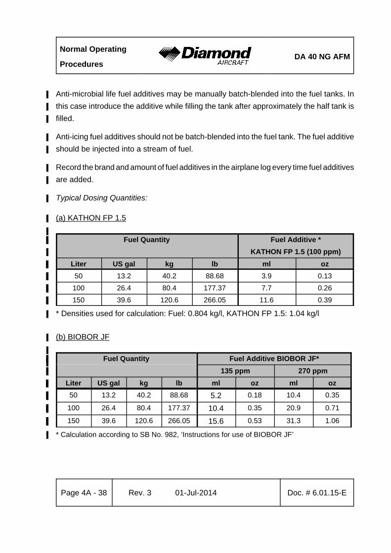
Normal Operating
ProceduresDA 40 NG AFM
Page 4A - 38 Rev. 3 01-Jul-2014 Doc. # 6.01.15-E
Anti-microbial life fuel additives may be manually batch-blended into the fuel tanks. In%
this case introduce the additive while filling the tank after approximately the half tank is%
filled.%
Anti-icing fuel additives should not be batch-blended into the fuel tank. The fuel additive%
should be injected into a stream of fuel.%
Record the brand and amount of fuel additives in the airplane log every time fuel additives%
are added.%
Typical Dosing Quantities:%
(a) KATHON FP 1.5%
%Fuel Quantity% Fuel Additive *%
KATHON FP 1.5 (100 ppm)%
Liter% US gal% kg% lb% ml% oz%
50% 13.2% 40.2% 88.68% 3.9% 0.13%
100% 26.4% 80.4% 177.37% 7.7% 0.26%
150% 39.6% 120.6% 266.05% 11.6% 0.39%
* Densities used for calculation: Fuel: 0.804 kg/l, KATHON FP 1.5: 1.04 kg/l%
(b) BIOBOR JF%
%Fuel Quantity% Fuel Additive BIOBOR JF*%%
135 ppm% 270 ppm%
Liter% US gal% kg% lb% ml% oz% ml% oz%
50% 13.2% 40.2% 88.68% 5.2% 0.18% 10.4% 0.35%
100% 26.4% 80.4% 177.37% 10.4% 0.35% 20.9% 0.71%
150% 39.6% 120.6% 266.05% 15.6% 0.53% 31.3% 1.06%
* Calculation according to SB No. 982, ‘Instructions for use of BIOBOR JF’%
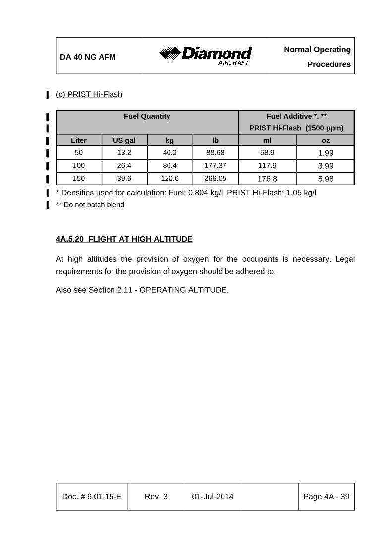
DA 40 NG AFMNormal Operating
Procedures
Doc. # 6.01.15-E Rev. 3 01-Jul-2014 Page 4A - 39
(c) PRIST Hi-Flash%
Fuel Quantity% Fuel Additive *, **%
PRIST Hi-Flash (1500 ppm)%
Liter% US gal% kg% lb% ml% oz%
50% 13.2% 40.2% 88.68% 58.9% 1.99%
100% 26.4% 80.4% 177.37% 117.9% 3.99%
150% 39.6% 120.6% 266.05% 176.8% 5.98%
* Densities used for calculation: Fuel: 0.804 kg/l, PRIST Hi-Flash: 1.05 kg/l%
** Do not batch blend%
4A.5.20 FLIGHT AT HIGH ALTITUDE
At high altitudes the provision of oxygen for the occupants is necessary. Legal
requirements for the provision of oxygen should be adhered to.
Also see Section 2.11 - OPERATING ALTITUDE.
Normal Operating
ProceduresDA 40 NG AFM
Page 4A - 40 Rev. 3 01-Jul-2014 Doc. # 6.01.15-E
Intentionally left blank.
DA 40 NG AFMAbnormal Operating
Procedures
Doc. # 6.01.15-E Rev. 3 01-Jul-2014 Page 4B - 1
CHAPTER 4B
ABNORMAL OPERATING PROCEDURES
Page
4B.1 PRECAUTIONARY LANDING . . . . . . . . . . . . . . . . . . . . . . . . . . . . 4B-2
4B.2 INSTRUMENT INDICATIONS OUTSIDE OF GREEN RANGE . . . 4B-4
4B.2.1 RPM . . . . . . . . . . . . . . . . . . . . . . . . . . . . . . . . . . . . . . . . . 4B-4
4B.2.2 COOLANT TEMPERATURE . . . . . . . . . . . . . . . . . . . . . . . 4B-5
4B.2.3 OIL TEMPERATURE . . . . . . . . . . . . . . . . . . . . . . . . . . . . 4B-6
4B.2.4 OIL PRESSURE . . . . . . . . . . . . . . . . . . . . . . . . . . . . . . . . 4B-7
4B.2.5 GEARBOX TEMPERATURE . . . . . . . . . . . . . . . . . . . . . . 4B-8
4B.2.6 FUEL TEMPERATURE . . . . . . . . . . . . . . . . . . . . . . . . . . . 4B-9
4B.2.7 VOLTAGE . . . . . . . . . . . . . . . . . . . . . . . . . . . . . . . . . . . . 4B-10
4B.2.8 CURRENT . . . . . . . . . . . . . . . . . . . . . . . . . . . . . . . . . . . 4B-11
4B.3 CAUTION-ALERTS . . . . . . . . . . . . . . . . . . . . . . . . . . . . . . . . . . . 4B-12
4B.3.1 ECU A FAILURE . . . . . . . . . . . . . . . . . . . . . . . . . . . . . . . 4B-12
4B.3.2 ECU B FAILURE . . . . . . . . . . . . . . . . . . . . . . . . . . . . . . . 4B-14
4B.3.3 FUEL QUANTITY LOW . . . . . . . . . . . . . . . . . . . . . . . . . 4B-16
4B.3.4 COOLANT LEVEL . . . . . . . . . . . . . . . . . . . . . . . . . . . . . 4B-18
4B.3.5 PITOT HEATING FAILURE . . . . . . . . . . . . . . . . . . . . . . 4B-19
4B.3.6 ENGINE CAUTION (IF WHITE WIRE ANNUNCIATOR PANEL IS
INSTALLED) . . . . . . . . . . . . . . . . . . . . . . . . . . . . . . . . . . . 4B-19
4B.4 CANOPY IN COOLING GAP POSITION . . . . . . . . . . . . . . . . . . 4B-20
4B.5 FAILURES IN FLAP OPERATING SYSTEM . . . . . . . . . . . . . . . 4B-21
4B.6 LIGHTNING STRIKE . . . . . . . . . . . . . . . . . . . . . . . . . . . . . . . . . . 4B-23
4B.7 LANDING WITH MASS ABOVE MAXIMUM LANDING MASS . . 4B-24
4B.8 STARTING ENGINE WITH EXTERNAL POWER . . . . . . . . . . . . 4B-25%
4B.8.1 BEFORE STARTING ENGINE . . . . . . . . . . . . . . . . . . . . 4B-25
4B.8.2 STARTING ENGINE . . . . . . . . . . . . . . . . . . . . . . . . . . . . 4B-27%
Abnormal Operating
ProceduresDA 40 NG AFM
Page 4B - 2 Rev. 3 01-Jul-2014 Doc. # 6.01.15-E
4B.1 PRECAUTIONARY LANDING
NOTE
A landing of this type is only necessary when there is a
reasonable suspicion that due to operational factors such as
fuel shortage, weather conditions, etc. the possibility of
endangering the airplane and its occupants by continuing the
flight cannot be excluded. The pilot is required to decide
whether or not a controlled landing in a field represents a
lower risk than the attempt to reach the nearest airfield under
all circumstances.
NOTE
If no level landing area is available, a landing on an upward
slope should be sought.
1. Select appropriate landing area.
2. Consider wind.
3. Approach:
If possible, the landing area should be overflown at a suitable height in order to
recognize obstacles. The degree of offset at each part of the circuit will allow the
wind speed and direction to be assessed.
4. ATC . . . . . . . . . . . . . . . . . . . . . . . . . . . . . . . advise
Perform procedures according to Normal Procedures 4A.5.12 - APPROACH & LANDING.
5. Touchdown . . . . . . . . . . . . . . . . . . . . . . . . . . with the lowest possible airspeed
CONTINUED
DA 40 NG AFMAbnormal Operating
Procedures
Doc. # 6.01.15-E Rev. 3 01-Jul-2014 Page 4B - 3
CAUTION
If sufficient time is remaining, the risk of fire in the event of
a collision with obstacles can be reduced as follows after a
safe touch-down:
6. ENGINE MASTER . . . . . . . . . . . . . . . . . . OFF
7. Fuel valve . . . . . . . . . . . . . . . . . . . . . . . . . OFF
8. ELECTRIC MASTER . . . . . . . . . . . . . . . . OFF
END OF CHECKLIST
Abnormal Operating
ProceduresDA 40 NG AFM
Page 4B - 4 Rev. 3 01-Jul-2014 Doc. # 6.01.15-E
4B.2 INSTRUMENT INDICATIONS OUTSIDE OF GREEN RANGE
4B.2.1 RPM
High RPM
1. Reduce power.
2. Keep RPM within the green range using the POWER lever.
NOTE
An RPM in the yellow range is permissible for up to 5 minutes
if required, e.g. for go-around or take-off.
If the above mentioned measures do not solve the problem refer to Section
3.3.6 - DEFECTIVE RPM REGULATING SYSTEM.
3. Land at the nearest suitable airfield.
END OF CHECKLIST
DA 40 NG AFMAbnormal Operating
Procedures
Doc. # 6.01.15-E Rev. 3 01-Jul-2014 Page 4B - 5
4B.2.2 COOLANT TEMPERATURE
(a) High Coolant Temperature
Proceed according to:
Section 3.2.1 - ENGINE TEMPERATURE.
(b) Low Coolant Temperature
- Check for COOL LVL (if G1000 is installed) or WATERLEV (if SED is installed)
caution message (low coolant level).
NOTE
During an extended descent from high altitudes with a low
power setting coolant temperature may decrease. In this case
an increase in power and a decrease in airspeed can help.
COOL LVL (if G1000 is installed) or WATERLEV (if SED is installed) Caution Message
Displayed:
- Reduce power.
- Expect loss of coolant.
WARNING
A further decrease in coolant temperature must be expected.
Prepare for an engine failure in accordance with Section
3.3.3 - ENGINE TROUBLESHOOTING IN FLIGHT.
END OF CHECKLIST
Abnormal Operating
ProceduresDA 40 NG AFM
Page 4B - 6 Rev. 3 01-Jul-2014 Doc. # 6.01.15-E
4B.2.3 OIL TEMPERATURE
a) High Oil Temperature
Proceed according to:
Section 3.2.2 - OIL TEMPERATURE.
(b) Low Oil Temperature
NOTE
During an extended descent from high altitudes with a low
power setting oil temperature may decrease. In this case an
increase in power can help.
- Increase power.
- Reduce airspeed.
END OF CHECKLIST

DA 40 NG AFMAbnormal Operating
Procedures
Doc. # 6.01.15-E Rev. 3 01-Jul-2014 Page 4B - 7
4B.2.4 OIL PRESSURE
High Oil Pressure
- Check oil temperature.%
- Check coolant temperature.%
%
If the temperature is within the green range:%
- Expect false oil pressure indication. Keep monitoring temperatures.%
%
If the temperature is outside of the green range:%
- Reduce power on engine.%
WARNING%
Land at the nearest suitable airfield. Prepare for an engine%
failure in accordance with 3.7.1 - EMERGENCY LANDING%
WITH ENGINE OFF.%
NOTE%
At low oil temperature high oil pressure may occur which%
could lead to an oil pressure warning. In this case reduce the%
power setting until the warning disappears and conduct the%
warm up with this reduced setting.%
END OF CHECKLIST
Abnormal Operating
ProceduresDA 40 NG AFM
Page 4B - 8 Rev. 3 01-Jul-2014 Doc. # 6.01.15-E
4B.2.5 GEARBOX TEMPERATURE
High Gearbox Temperature
Proceed according to:
Section 3.2.4 - GEARBOX TEMPERATURE.
NOTE
A cautionary (yellow) gearbox temperature range is not
imposed by the engine manufacturer. However, there is a
delay between power changes and gearbox temperature.
Therefore, a cautionary range has been added to the G1000
(if installed) or MED (if installed) gearbox temperature
instrument solely to make the pilot attentive to the gearbox
temperature approaching the maximum allowable limit. There
is no specific time limit associated with operating in the
cautionary gearbox temperature range.
END OF CHECKLIST
DA 40 NG AFMAbnormal Operating
Procedures
Doc. # 6.01.15-E Rev. 3 01-Jul-2014 Page 4B - 9
4B.2.6 FUEL TEMPERATURE
(a) High Fuel Temperature
Proceed according to:
Section 3.2.5 - L/R FUEL TEMPERATURE.
(b) Low Fuel Temperature
- Increase power.
- Reduce airspeed.
CAUTION
At low ambient temperature conditions and/or at high
airspeeds with low power settings, it can be assumed that
the above mentioned procedure will increase the
temperature(s). If the fuel temperature does not return to the
green range perform a precautionary landing on the nearest
suitable airfield. Prepare for an engine failure in accordance
with Section 3.3.4 - ENGINE FAILURE IN FLIGHT.
END OF CHECKLIST
Abnormal Operating
ProceduresDA 40 NG AFM
Page 4B - 10 Rev. 3 01-Jul-2014 Doc. # 6.01.15-E
4B.2.7 VOLTAGE
(a) Low Voltage Indication on the Ground with Engine Running
- Terminate flight preparation.
(b) Low Voltage During Flight
1. Circuit breakers . . . . . . . . . . . . . . . . . . . . . . check
2. Electrical equipment . . . . . . . . . . . . . . . . . . . OFF if not needed
If Low Voltage Condition Still Exists:
- Follow procedure in Section 3.2.8 - ALTERNATOR FAIL.
NOTE
This procedure is applicable if either the voltmeter is out of
the green range or VOLTS LOW (if G1000 is installed) or
LOW VOLTS (if White Wire annunciator panel is installed)
is indicated.
END OF CHECKLIST
DA 40 NG AFMAbnormal Operating
Procedures
Doc. # 6.01.15-E Rev. 3 01-Jul-2014 Page 4B - 11
4B.2.8 CURRENT
This caution is indicated when the consumption of electric power exceeds 60 A.
1. Electrical equipment . . . . . . . . . . . . . . . . . . . switch OFF as necessary and
possible to reduce electric load
If the problem does not clear:
2. Land on nearest suitable airfield.
END OF CHECKLIST
Abnormal Operating
ProceduresDA 40 NG AFM
Page 4B - 12 Rev. 3 01-Jul-2014 Doc. # 6.01.15-E
4B.3 CAUTION-ALERTS
4B.3.1 ECU A FAILURE%
* Engine ECU A has failed or
* is being tested during FADEC test procedure before take-off check.
Depending on the type of failure, the ECU failure cautions are either ‘non latched’, i.e.%
the caution message disappears after the cause of the caution is no longer present or%
‘latched’, i.e. the caution massage remains until cleared through maintenance action. A%
‘non-latched’ caution clears itself only on the active ECU. ‘Non latched’ caution messages%
can be cleared on the passive ECU by switching to that ECU with the voter switch.%
(a) ECU A Caution on the Ground
1. ALTERNATE AIR . . . . . . . . . . . . . . . . . . . check CLOSED%
2. Fuel pump . . . . . . . . . . . . . . . . . . . . . . . . OFF%
3. VOTER switch . . . . . . . . . . . . . . . . . . . . . check AUTO%
4. ECU B caution . . . . . . . . . . . . . . . . . . . . . check OFF%
5. VOTER switch . . . . . . . . . . . . . . . . . . . . . ECU A%
6. Wait . . . . . . . . . . . . . . . . . . . . . . . . . . . . . 5 seconds%
7. VOTER switch . . . . . . . . . . . . . . . . . . . . . AUTO%
%
If the ECU A caution persists: - terminate flight preparation.%
(b) ECU A Caution During Flight
NOTE
In case of a failure in the electronic ECU (Engine Control Unit)
'A' the system automatically switches to ECU 'B'.
DA 40 NG AFMAbnormal Operating
Procedures
Doc. # 6.01.15-E Rev. 3 01-Jul-2014 Page 4B - 13
1. ALTERNATE AIR . . . . . . . . . . . . . . . . . . . OPEN
2. Fuel pump . . . . . . . . . . . . . . . . . . . . . . . . ON
3. Circuit breakers . . . . . . . . . . . . . . . . . . . . check / reset if necessary
4. VOTER switch . . . . . . . . . . . . . . . . . . . . . AUTO
If the ECU A caution persists: - land at the next suitable airfield. After landing, you
may use (a) ECU A Caution on the ground as ECU
caution clearing procedure.
NOTE%
An ECU FAIL caution is caused by various types of%
malfunctions. These include internal ECU problems, sensor%
failure or insufficient performance of air-, fuel- or electrical%
supply system (e.g. air filter icing).%
NOTE
If additional engine problems are observed refer to Section
3.3.3 - ENGINE TROUBLESHOOTING IN FLIGHT.
END OF CHECKLIST
Abnormal Operating
ProceduresDA 40 NG AFM
Page 4B - 14 Rev. 3 01-Jul-2014 Doc. # 6.01.15-E
4B.3.2 ECU B FAILURE
* Engine ECU B has failed or
* is being tested during FADEC test procedure before take-off check.
Depending on the type of failure, the ECU failure cautions are either ‘non latched’, i.e.%
the caution message disappears after the cause of the caution is no longer present or%
‘latched’, i.e. the caution massage remains until cleared through maintenance action. A%
‘non-latched’ caution clears itself only on the active ECU. ‘Non latched’ caution messages%
can be cleared on the passive ECU by switching to that ECU with the voter switch.%
(a) ECU B Caution on the Ground
1. ALTERNATE AIR . . . . . . . . . . . . . . . . . . . check CLOSED%
2. Fuel Pump . . . . . . . . . . . . . . . . . . . . . . . . OFF%
3. VOTER switch . . . . . . . . . . . . . . . . . . . . . check AUTO%
4. ECU A caution . . . . . . . . . . . . . . . . . . . . . check OFF%
5. VOTER switch . . . . . . . . . . . . . . . . . . . . . ECU B%
6. Wait . . . . . . . . . . . . . . . . . . . . . . . . . . . . . 5 seconds%
7. VOTER switch . . . . . . . . . . . . . . . . . . . . . AUTO%
%
If the ECU B caution persists: - terminate flight preparation.%
(b) ECU B Caution During Flight
NOTE
In case of a failure in the electronic ECU (Engine Control Unit)
'B' the system automatically switches to ECU 'A'.
CONTINUED%
DA 40 NG AFMAbnormal Operating
Procedures
Doc. # 6.01.15-E Rev. 3 01-Jul-2014 Page 4B - 15
1. ALTERNATE AIR . . . . . . . . . . . . . . . . . . . OPEN%
2. Fuel pump . . . . . . . . . . . . . . . . . . . . . . . . ON%
3. Circuit breakers . . . . . . . . . . . . . . . . . . . . check / reset if necessary%
4. VOTER switch . . . . . . . . . . . . . . . . . . . . . AUTO%
%
If the ECU B caution persists: - land at the next suitable airfield. After landing, you%
may use (a) ECU B Caution on the ground as ECU%
caution clearing procedure.%
NOTE%
An ECU FAIL caution is caused by various types of%
malfunctions. These include internal ECU problems, sensor%
failure or insufficient performance of air-, fuel- or electrical%
supply system (e.g. air filter icing).%
NOTE
If additional engine problems are observed refer to Section
3.3.3 - ENGINE TROUBLESHOOTING IN FLIGHT.
END OF CHECKLIST
Abnormal Operating
ProceduresDA 40 NG AFM
Page 4B - 16 Rev. 3 01-Jul-2014 Doc. # 6.01.15-E
4B.3.3 FUEL QUANTITY LOW
Left fuel quantity is low.
1. Fuel transfer pump . . . . . . . . . . . . . . . . . . . . ON
2. Fuel quantity . . . . . . . . . . . . . . . . . . . . . . . . . check
CAUTION
As soon as the amount of usable fuel in the main tank is low,
a caution message is displayed. The indication is calibrated
for straight and level flight. The caution message may be
triggered during turns which are flown with slip, or while
taxiing in curves.
If FUEL LOW (if G1000 is installed) or LOW FUEL (if White Wire Annunciator Panel is
installed) Caution Is Caused By Un-Coordinated Flight:
CAUTION
Prolonged un-coordinated flight can cause fuel starvation to
the engine resulting in a loss of power.
3. Return to coordinated flight (not more than approx. half a ball sideslip, 3° - 5° bank)
If the Caution Does Not Extinguish:
- Expect loss of fuel.
4. Fuel valve . . . . . . . . . . . . . . . . . . . . . . . . . . . EMERGENCY
5. Fuel transfer pump . . . . . . . . . . . . . . . . . . . . OFF
CONTINUED
DA 40 NG AFMAbnormal Operating
Procedures
Doc. # 6.01.15-E Rev. 3 01-Jul-2014 Page 4B - 17
If the Caution Does Not Extinguish:
- Be prepared for an emergency landing.
- Proceed in accordance with Section 3.7.1 - EMERGENCY LANDING WITH ENGINE
OFF.
WARNING
If air enters the high pressure fuel pump (e.g. empty fuel
tank), an inspection of the pump is necessary prior to next
flight.
END OF CHECKLIST
Abnormal Operating
ProceduresDA 40 NG AFM
Page 4B - 18 Rev. 3 01-Jul-2014 Doc. # 6.01.15-E
4B.3.4 COOLANT LEVEL
Engine coolant level is low.
A low coolant caution alert may indicate a loss of coolant. This will subsequently lead
to decreased engine cooling capability/loss of engine power due to engine failure.
1. Annunciations / engine instruments . . . . . . . monitor
Refer to Section 4B.2.2 - COOLANT TEMPERATURE.
NOTE
The indication is calibrated for straight and level flight. The
caution message may be triggered during turns which are
flown with slip, or while taxiing in curves.
END OF CHECKLIST
DA 40 NG AFMAbnormal Operating
Procedures
Doc. # 6.01.15-E Rev. 3 01-Jul-2014 Page 4B - 19
4B.3.5 PITOT HEATING FAILURE
Pitot heating system has failed.
If in Icing Conditions:
1. Expect loss of airspeed indication.
2. Leave icing zone / refer to Section 3.9.1 - ICING.
END OF CHECKLIST
4B.3.6 ENGINE CAUTION (IF WHITE WIRE ANNUNCIATOR PANEL IS INSTALLED)
Engine limit exceeded.
1. Engine indications . . . . . . . . . . . . . . . . . . . . check
2. Acknowledge button . . . . . . . . . . . . . . . . . . . press
NOTE
If an indication is near the end of the green range, it may
happen that it switches over to the yellow or red range for a
short time. This will also cause the ENGINE caution light to
illuminate.
NOTE
If an indication is outside of the green range, proceed in
accordance with 4B.2 - INSTRUMENT INDICATIONS
OUTSIDE OF THE GREEN RANGE.
END OF CHECKLIST
Abnormal Operating
ProceduresDA 40 NG AFM
Page 4B - 20 Rev. 3 01-Jul-2014 Doc. # 6.01.15-E
4B.4 CANOPY IN COOLING GAP POSITION
CAUTION
If take-off was inadvertently done with the canopy in the
cooling gap position, do not attempt to close the canopy in
flight. Land the airplane and close the canopy on ground.
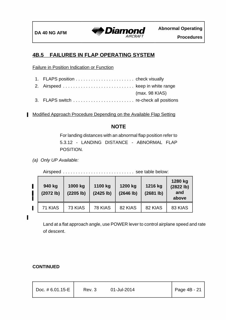
DA 40 NG AFMAbnormal Operating
Procedures
Doc. # 6.01.15-E Rev. 3 01-Jul-2014 Page 4B - 21
4B.5 FAILURES IN FLAP OPERATING SYSTEM
Failure in Position Indication or Function
1. FLAPS position . . . . . . . . . . . . . . . . . . . . . . . check visually
2. Airspeed . . . . . . . . . . . . . . . . . . . . . . . . . . . . keep in white range
(max. 98 KIAS)
3. FLAPS switch . . . . . . . . . . . . . . . . . . . . . . . . re-check all positions
Modified Approach Procedure Depending on the Available Flap Setting%
NOTE
For landing distances with an abnormal flap position refer to
5.3.12 - LANDING DISTANCE - ABNORMAL FLAP
POSITION.
(a) Only UP Available:
Airspeed . . . . . . . . . . . . . . . . . . . . . . . . . . . . see table below:
940 kg
(2072 lb)
1000 kg
(2205 lb)
1100 kg%
(2425 lb)%
1200 kg%
(2646 lb)%
1216 kg
(2681 lb)
1280 kg(2822 lb)
and%above%
71 KIAS 73 KIAS 78 KIAS 82 KIAS% 82 KIAS 83 KIAS
%
Land at a flat approach angle, use POWER lever to control airplane speed and rate
of descent.
CONTINUED
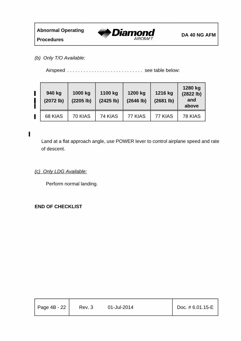
Abnormal Operating
ProceduresDA 40 NG AFM
Page 4B - 22 Rev. 3 01-Jul-2014 Doc. # 6.01.15-E
(b) Only T/O Available:
Airspeed . . . . . . . . . . . . . . . . . . . . . . . . . . . . see table below:
940 kg
(2072 lb)
1000 kg
(2205 lb)
1100 kg%
(2425 lb)%
1200 kg%
(2646 lb)%
1216 kg
(2681 lb)
1280 kg(2822 lb)
and%above%
68 KIAS 70 KIAS 74 KIAS% 77 KIAS% 77 KIAS 78 KIAS
%
Land at a flat approach angle, use POWER lever to control airplane speed and rate
of descent.
(c) Only LDG Available:
Perform normal landing.
END OF CHECKLIST
DA 40 NG AFMAbnormal Operating
Procedures
Doc. # 6.01.15-E Rev. 3 01-Jul-2014 Page 4B - 23
4B.6 LIGHTNING STRIKE
1. Airspeed . . . . . . . . . . . . . . . . . . . . . . . . . . . . as low as practicable, do not
exceed vO (refer to Section 2.2)
2. Grasp airplane controls firmly
3. Autopilot (if installed) . . . . . . . . . . . . . . . . . . . disengage (check)
4. PFD (if G1000 is installed) /
backup instruments . . . . . . . . . . . . . . . . . . . verify periodically
5. Continue flight below vO (refer to Section 2.2)
6. Land on the next suitable airfield
CAUTION
Due to possible damage to the airplane obey the following
instructions:
- Avoid abrupt or full control surface movements.
- Avoid high g-loads on the airframe.
- Avoid high yaw angles.
- Avoid turbulent air as far as possible (e.g. lee effects).
- Do not fly into areas of known or forecast icing.
END OF CHECKLIST
Abnormal Operating
ProceduresDA 40 NG AFM
Page 4B - 24 Rev. 3 01-Jul-2014 Doc. # 6.01.15-E
4B.7 LANDING WITH MASS ABOVE MAXIMUM LANDING MASS%
NOTE
Refer to Section 4A.5.12 - APPROACH AND LANDING for
landings with a mass up to 1216 kg (2681 lb), and if MÄM 40-%
574 is carried out for landings with a mass up to 1280 kg%
(2822 lb).%
%
Perform landing approach and landing according to Chapter 4A, but maintain an increased
airspeed during final landing approach.%
Approach speed . . . . . . . . . . . . . . . . . . . . . . 77 KIAS for a mass above 1280 kg%
. . . . . . . . . . . . . . . . . . . . . . . . . . . . . . . . . . . (2822 lb), flaps LDG%
END OF CHECKLIST
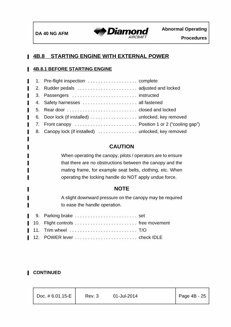
DA 40 NG AFMAbnormal Operating
Procedures
Doc. # 6.01.15-E Rev. 3 01-Jul-2014 Page 4B - 25
4B.8 STARTING ENGINE WITH EXTERNAL POWER%
4B.8.1 BEFORE STARTING ENGINE%
1. Pre-flight inspection . . . . . . . . . . . . . . . . . . . complete%
2. Rudder pedals . . . . . . . . . . . . . . . . . . . . . . . adjusted and locked%
3. Passengers . . . . . . . . . . . . . . . . . . . . . . . . . instructed%
4. Safety harnesses . . . . . . . . . . . . . . . . . . . . . all fastened%
5. Rear door . . . . . . . . . . . . . . . . . . . . . . . . . . . closed and locked%
6. Door lock (if installed) . . . . . . . . . . . . . . . . . . unlocked, key removed%
7. Front canopy . . . . . . . . . . . . . . . . . . . . . . . . Position 1 or 2 (“cooling gap”)%
8. Canopy lock (if installed) . . . . . . . . . . . . . . . unlocked, key removed%
%
CAUTION%
When operating the canopy, pilots / operators are to ensure%
that there are no obstructions between the canopy and the%
mating frame, for example seat belts, clothing, etc. When%
operating the locking handle do NOT apply undue force.%
NOTE%
A slight downward pressure on the canopy may be required%
to ease the handle operation.%
9. Parking brake . . . . . . . . . . . . . . . . . . . . . . . . set%
10. Flight controls . . . . . . . . . . . . . . . . . . . . . . . . free movement%
11. Trim wheel . . . . . . . . . . . . . . . . . . . . . . . . . . T/O%
12. POWER lever . . . . . . . . . . . . . . . . . . . . . . . . check IDLE%
CONTINUED%
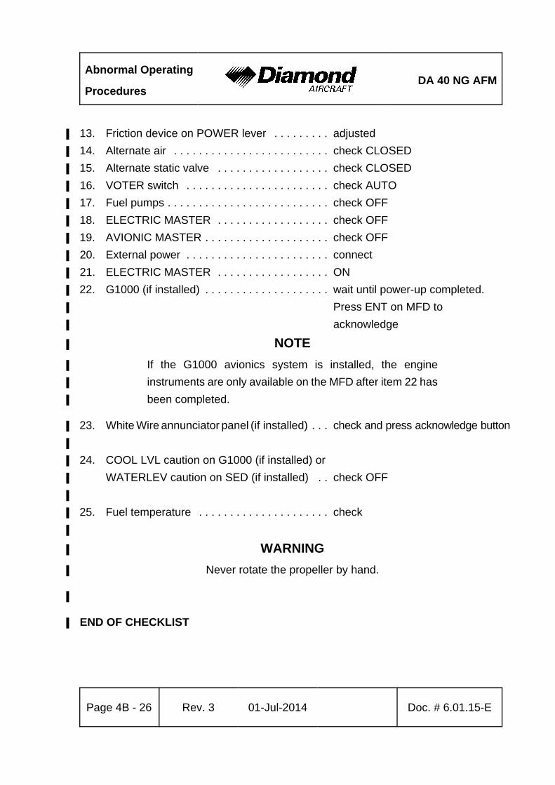
Abnormal Operating
ProceduresDA 40 NG AFM
Page 4B - 26 Rev. 3 01-Jul-2014 Doc. # 6.01.15-E
13. Friction device on POWER lever . . . . . . . . . adjusted%
14. Alternate air . . . . . . . . . . . . . . . . . . . . . . . . . check CLOSED%
15. Alternate static valve . . . . . . . . . . . . . . . . . . check CLOSED%
16. VOTER switch . . . . . . . . . . . . . . . . . . . . . . . check AUTO%
17. Fuel pumps . . . . . . . . . . . . . . . . . . . . . . . . . . check OFF%
18. ELECTRIC MASTER . . . . . . . . . . . . . . . . . . check OFF%
19. AVIONIC MASTER . . . . . . . . . . . . . . . . . . . . check OFF%
20. External power . . . . . . . . . . . . . . . . . . . . . . . connect%
21. ELECTRIC MASTER . . . . . . . . . . . . . . . . . . ON%
22. G1000 (if installed) . . . . . . . . . . . . . . . . . . . . wait until power-up completed. %
Press ENT on MFD to%
acknowledge%
NOTE%
If the G1000 avionics system is installed, the engine%
instruments are only available on the MFD after item 22 has%
been completed.%
23. White Wire annunciator panel (if installed) . . . check and press acknowledge button%
%
24. COOL LVL caution on G1000 (if installed) or%
WATERLEV caution on SED (if installed) . . check OFF%
%
25. Fuel temperature . . . . . . . . . . . . . . . . . . . . . check%
%
WARNING%
Never rotate the propeller by hand.%
%
END OF CHECKLIST%

DA 40 NG AFMAbnormal Operating
Procedures
Doc. # 6.01.15-E Rev. 3 01-Jul-2014 Page 4B - 27
4B.8.2 STARTING ENGINE%
CAUTION%
Do not operate the engine starter motor for more than%
10 seconds, because of possible overheating of the starter%
motor.%
If the STARTER annunciation on the G1000 (if installed) or%
START on the White Wire annunciator panel (if installed) %
comes on after the engine has started and the START KEY%
has been released, set the ENGINE MASTER to OFF and%
investigate the problem.%
WARNING%
If the oil pressure has not moved from the red range within%
3 seconds after starting, set the ENGINE MASTER switch to%
OFF and investigate problem.%
NOTE%
At low ambient temperatures it is possible that the engine will%
not start at the first attempt. In this case wait 60 seconds%
between the start attempts.%
%
1. Strobe lights (ACL) . . . . . . . . . . . . . . . . . . . . ON%
2. ENGINE MASTER . . . . . . . . . . . . . . . . . . . . ON%
CONTINUED%
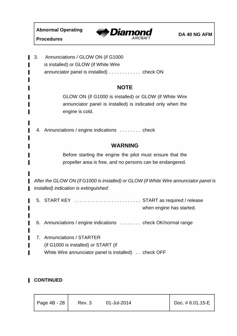
Abnormal Operating
ProceduresDA 40 NG AFM
Page 4B - 28 Rev. 3 01-Jul-2014 Doc. # 6.01.15-E
3. Annunciations / GLOW ON (if G1000 %
is installed) or GLOW (if White Wire %
annunciator panel is installed) . . . . . . . . . . . . check ON%
%
NOTE%
GLOW ON (if G1000 is installed) or GLOW (if White Wire%
annunciator panel is installed) is indicated only when the%
engine is cold.%
%
4. Annunciations / engine indications . . . . . . . . check%
%
WARNING%
Before starting the engine the pilot must ensure that the%
propeller area is free, and no persons can be endangered.%
%
After the GLOW ON (if G1000 is installed) or GLOW (if White Wire annunciator panel is%
installed) indication is extinguished:%
5. START KEY . . . . . . . . . . . . . . . . . . . . . . . . . START as required / release%
when engine has started.%
%
6. Annunciations / engine indications . . . . . . . . check OK/normal range%
%
7. Annunciations / STARTER %
(if G1000 is installed) or START (if %
White Wire annunciator panel is installed) . . check OFF%
CONTINUED%
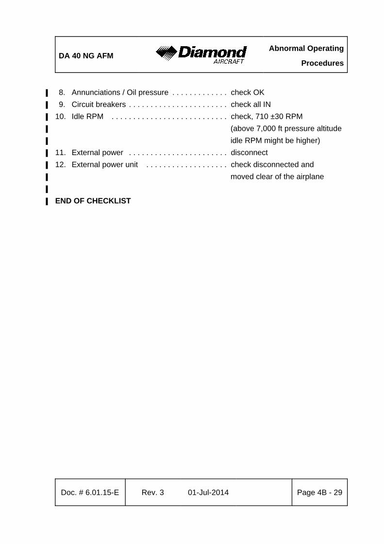
DA 40 NG AFMAbnormal Operating
Procedures
Doc. # 6.01.15-E Rev. 3 01-Jul-2014 Page 4B - 29
8. Annunciations / Oil pressure . . . . . . . . . . . . . check OK%
9. Circuit breakers . . . . . . . . . . . . . . . . . . . . . . . check all IN %
10. Idle RPM . . . . . . . . . . . . . . . . . . . . . . . . . . . check, 710 ±30 RPM%
(above 7,000 ft pressure altitude%
idle RPM might be higher)%
11. External power . . . . . . . . . . . . . . . . . . . . . . . disconnect%
12. External power unit . . . . . . . . . . . . . . . . . . . check disconnected and%
moved clear of the airplane%
%
END OF CHECKLIST%
Abnormal Operating
ProceduresDA 40 NG AFM
Page 4B - 30 Rev. 3 01-Jul-2014 Doc. # 6.01.15-E
Intentionally left blank.
DA 40 NG AFM Performance
Doc. # 6.01.15-E Rev. 3 01-Jul-2014 Page 5 - 1
CHAPTER 5
PERFORMANCE
Page
5.1 INTRODUCTION . . . . . . . . . . . . . . . . . . . . . . . . . . . . . . . . . . . . . . . 5-2
5.2 USE OF THE PERFORMANCE TABLES AND DIAGRAMS . . . . . . 5-2
5.3 PERFORMANCE TABLES AND DIAGRAMS . . . . . . . . . . . . . . . . . 5-4
5.3.1 AIRSPEED CALIBRATION . . . . . . . . . . . . . . . . . . . . . . . . . . 5-4
5.3.2 FUEL FLOW . . . . . . . . . . . . . . . . . . . . . . . . . . . . . . . . . . . . . 5-5
5.3.3 PRESSURE ALTITUDE - DENSITY ALTITUDE . . . . . . . . . . 5-6
5.3.4 INTERNATIONAL STANDARD ATMOSPHERE . . . . . . . . . . 5-7
5.3.5 STALLING SPEEDS . . . . . . . . . . . . . . . . . . . . . . . . . . . . . . . 5-8
5.3.6 WIND COMPONENTS . . . . . . . . . . . . . . . . . . . . . . . . . . . . 5-10
5.3.7 TAKE-OFF DISTANCE . . . . . . . . . . . . . . . . . . . . . . . . . . . . 5-11
5.3.8 CLIMB PERFORMANCE - TAKE-OFF CLIMB . . . . . . . . . . 5-17
5.3.9 CLIMB PERFORMANCE - CRUISE CLIMB . . . . . . . . . . . . 5-20
5.3.10 TIME, FUEL AND DISTANCE TO CLIMB . . . . . . . . . . . . . 5-23%
5.3.11 CRUISE PERFORMANCE . . . . . . . . . . . . . . . . . . . . . . . . 5-26%
5.3.12 LANDING DISTANCES . . . . . . . . . . . . . . . . . . . . . . . . . . . 5-28%
5.3.13 LANDING DISTANCE - ABNORMAL FLAP POSITION . . 5-34%
5.3.14 GO-AROUND CLIMB PERFORMANCE . . . . . . . . . . . . . . 5-38%
5.3.15 GLIDE . . . . . . . . . . . . . . . . . . . . . . . . . . . . . . . . . . . . . . . . 5-41%
5.3.16 APPROVED NOISE DATA . . . . . . . . . . . . . . . . . . . . . . . . 5-42%
Performance DA 40 NG AFM
Page 5 - 2 Rev. 3 01-Jul-2014 Doc. # 6.01.15-E
5.1 INTRODUCTION
The performance tables and diagrams on the following pages are presented so that, on
the one hand, you can see what performance you can expect from your airplane, while
on the other they allow comprehensive and sufficiently accurate flight planning. The values
in the tables and the diagrams were obtained in the framework of the flight trials using
an airplane and power-plant in good condition, and corrected to the conditions of the
International Standard Atmosphere (ISA = 15 EC / 59 °F and 1,013.25 hPa / 29.92 inHg
at sea level).
The performance diagrams and tables do not take into account variations in pilot%
experience or a poorly maintained airplane. The performances given can be attained if
the procedures quoted in this manual are applied, and the airplane has been well
maintained.
Where appropriate, any flight performance degradation resulting from the absence of wheel
fairings is given as a percentage or different value.
5.2 USE OF THE PERFORMANCE TABLES AND DIAGRAMS
In order to illustrate the influence of a number of different variables, the performance data
is reproduced in the form of tables or diagrams. These contain sufficiently detailed
information so that conservative values can be selected and used for the determination
of adequate performance data for the planned flight.
For a conversion of units see Chapter 1.6 - UNITS OF MEASUREMENT.%
For temperatures, altitudes and weights between those provided, use a linear interpolation%
between the neighboring values. %
For weights below 1100 kg (2425 lb), use data for the lowest weight.%
DA 40 NG AFM Performance
Doc. # 6.01.15-E Rev. 3 01-Jul-2014 Page 5 - 3
For operation at outside air temperatures lower than provided in these tables, use data%
for lowest temperature shown.%
Use extreme caution for operation at outside air temperatures higher than provided in%
the tables (areas are indicated with a diagonal line).%
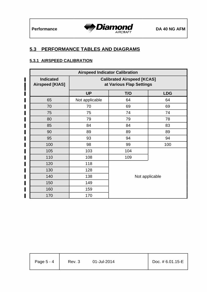
Performance DA 40 NG AFM
Page 5 - 4 Rev. 3 01-Jul-2014 Doc. # 6.01.15-E
5.3 PERFORMANCE TABLES AND DIAGRAMS
5.3.1 AIRSPEED CALIBRATION
Airspeed Indicator Calibration
Indicated%Airspeed [KIAS]%
Calibrated Airspeed [KCAS]%at Various Flap Settings%
%UP% T/O% LDG%
65% Not applicable% 64% 64%
70% 70% 69% 69%
75% 75% 74% 74%
80% 79% 79% 78%
85% 84% 84% 83%
90% 89% 89% 89%
95% 93% 94% 94%
100% 98% 99% 100%
105% 103% 104%%
110% 108% 109%%
120% 118%%%
130% 128%%%
140% 138% Not applicable%
150% 149%%%
160% 159%%
170% 170%%%
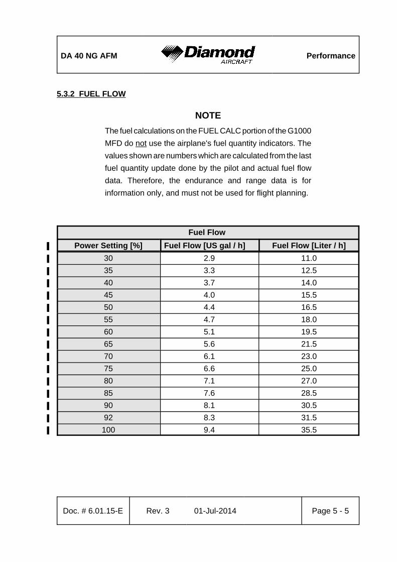
DA 40 NG AFM Performance
Doc. # 6.01.15-E Rev. 3 01-Jul-2014 Page 5 - 5
5.3.2 FUEL FLOW
NOTE
The fuel calculations on the FUEL CALC portion of the G1000
MFD do not use the airplane's fuel quantity indicators. The
values shown are numbers which are calculated from the last
fuel quantity update done by the pilot and actual fuel flow
data. Therefore, the endurance and range data is for
information only, and must not be used for flight planning.
Fuel Flow
Power Setting [%]% Fuel Flow [US gal / h]% Fuel Flow [Liter / h]%
30% 2.9% 11.0%
35% 3.3% 12.5%
40% 3.7% 14.0%
45% 4.0% 15.5%
50% 4.4% 16.5%
55% 4.7% 18.0%
60% 5.1% 19.5%
65% 5.6% 21.5%
70% 6.1% 23.0%
75% 6.6% 25.0%
80% 7.1% 27.0%
85% 7.6% 28.5%
90% 8.1% 30.5%
92% 8.3% 31.5%
100% 9.4% 35.5%
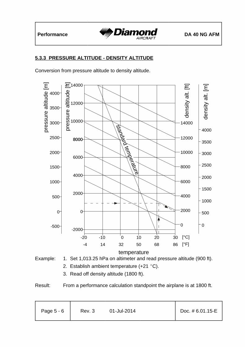
Performance DA 40 NG AFM
Page 5 - 6 Rev. 3 01-Jul-2014 Doc. # 6.01.15-E
standard temperature
densi
ty a
lt. [ft]
de
nsity
alt.
[m
]
pre
ssure
alti
tude
[m]
pre
ssur
e a
ltitu
de [
ft]
temperature
-2000
14000
12000
10000
12000
14000
10000
8000
6000
4000
2000
0
8000
8000
6000
4000
2000
0 0
500
1000
1500
2000
2500
3000
3500
4000
0
500
1000
1500
2000
2500
3000
3500
4000
-20 -10 0 10 20 30
-500
32 50 68 8614-4
[°C]
[°F]
5.3.3 PRESSURE ALTITUDE - DENSITY ALTITUDE
Conversion from pressure altitude to density altitude.
Example: 1. Set 1,013.25 hPa on altimeter and read pressure altitude (900 ft).
2. Establish ambient temperature (+21 EC).
3. Read off density altitude (1800 ft).
Result: From a performance calculation standpoint the airplane is at 1800 ft.
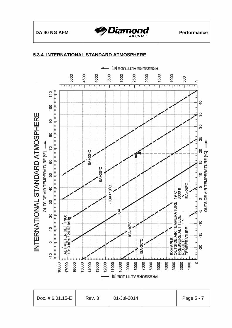
DA 40 NG AFM Performance
Doc. # 6.01.15-E Rev. 3 01-Jul-2014 Page 5 - 7
5.3.4 INTERNATIONAL STANDARD ATMOSPHERE

Performance DA 40 NG AFM
Page 5 - 8 Rev. 3 01-Jul-2014 Doc. # 6.01.15-E
5.3.5 STALLING SPEEDS
Stalling Speeds at Various Flight Masses
Indicated airspeed may not be accurate at stall.
Airspeeds, most forward CG, power off:
1000 kg%
(2205 lb)%
Bank Angle
0° 30° 45° 60°
Flaps% KIAS% KCAS% KIAS% KCAS% KIAS% KCAS% KIAS% KCAS%
UP% 58% 56% 59% 60% 64% 66% 76% 79%
T/O% 54% 53% 58% 57% 63% 63% 75% 74%
LDG% 55% 52% 56% 55% 61% 61% 72% 73%
1100 kg%
(2425 lb)%
Bank Angle
0° 30° 45° 60°
Flaps% KIAS% KCAS% KIAS% KCAS% KIAS% KCAS% KIAS% KCAS%
UP% 61% 59% 63% 64% 70% 71% 83% 84%
T/O% 56% 55% 60% 60% 66% 66% 79% 78%
LDG% 57% 54% 59% 58% 65% 65% 77% 77%
1200 kg%
(2646 lb)%
Bank Angle
0° 30° 45° 60°
Flaps% KIAS% KCAS% KIAS% KCAS% KIAS% KCAS% KIAS% KCAS%
UP% 64% 61% 67% 66% 73% 73% 86% 87%
T/O% 60% 57% 64% 62% 69% 68% 82% 81%
LDG% 59% 56% 62% 61% 68% 67% 81% 80%
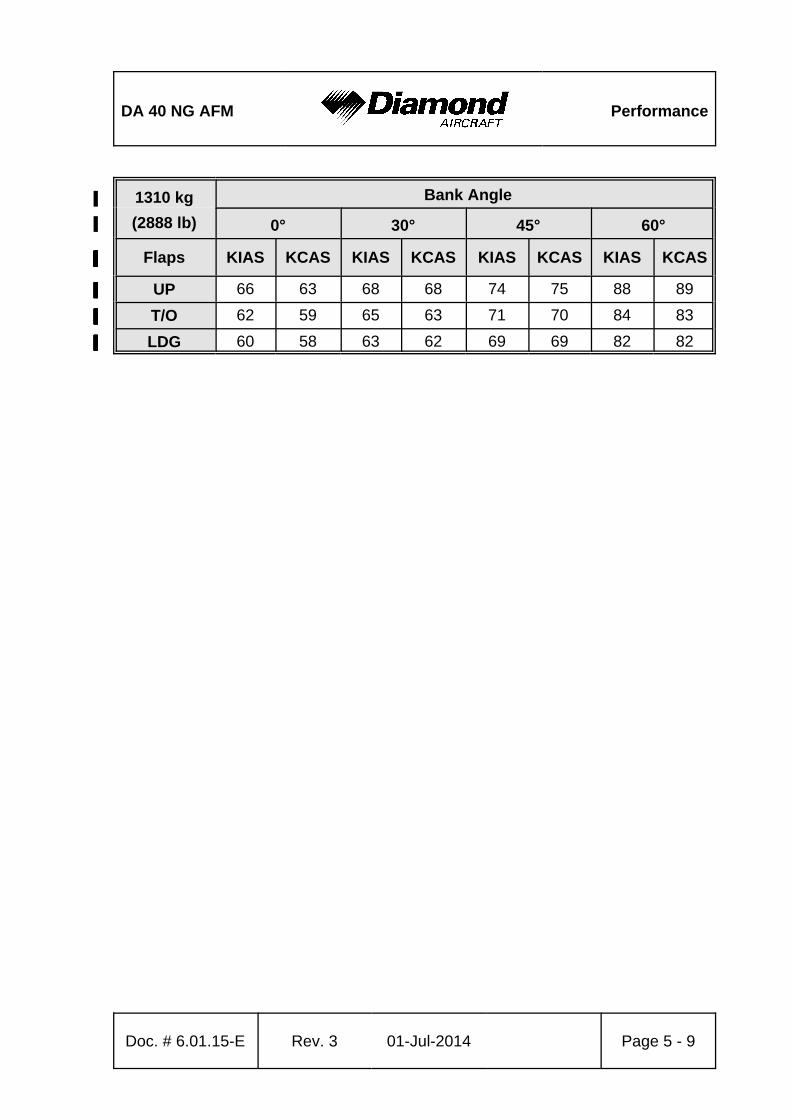
DA 40 NG AFM Performance
Doc. # 6.01.15-E Rev. 3 01-Jul-2014 Page 5 - 9
1310 kg%
(2888 lb)%
Bank Angle
0° 30° 45° 60°
Flaps% KIAS% KCAS% KIAS% KCAS% KIAS% KCAS% KIAS% KCAS%
UP% 66% 63% 68% 68% 74% 75% 88% 89%
T/O% 62% 59% 65% 63% 71% 70% 84% 83%
LDG% 60% 58% 63% 62% 69% 69% 82% 82%
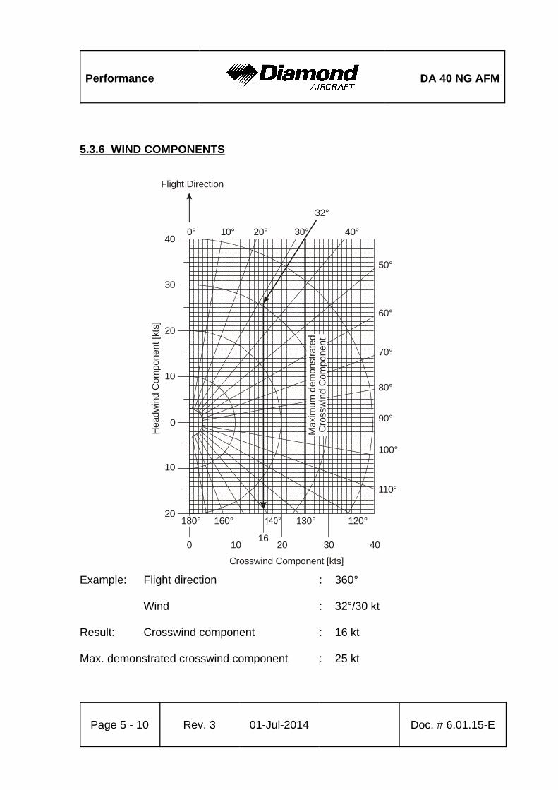
Performance DA 40 NG AFM
Page 5 - 10 Rev. 3 01-Jul-2014 Doc. # 6.01.15-E
0° 10° 20° 30° 40°
32°
50°
60°
70°
80°
90°
100°
110°
120°130°160°180°
0
10 2016
30 40
Crosswind Component [kts]
10
20
10
20
30
40
Hea
dw
ind
Com
pone
nt [kt
s]
Flight Direction
0
Max
imum
dem
onst
rate
dC
ross
win
d C
ompo
nent
5.3.6 WIND COMPONENTS
Example: Flight direction : 360°
Wind : 32°/30 kt
Result: Crosswind component : 16 kt
Max. demonstrated crosswind component : 25 kt
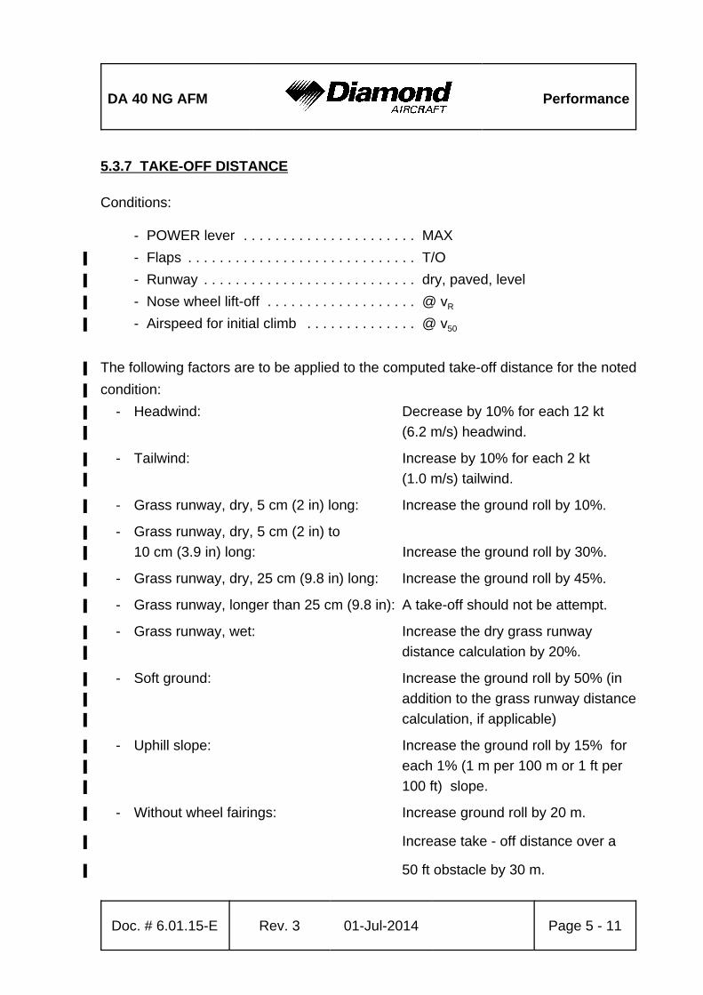
DA 40 NG AFM Performance
Doc. # 6.01.15-E Rev. 3 01-Jul-2014 Page 5 - 11
5.3.7 TAKE-OFF DISTANCE
Conditions:
- POWER lever . . . . . . . . . . . . . . . . . . . . . . MAX
- Flaps . . . . . . . . . . . . . . . . . . . . . . . . . . . . . T/O%
- Runway . . . . . . . . . . . . . . . . . . . . . . . . . . . dry, paved, level%
- Nose wheel lift-off . . . . . . . . . . . . . . . . . . . @ vR%
- Airspeed for initial climb . . . . . . . . . . . . . . @ v50%
The following factors are to be applied to the computed take-off distance for the noted%
condition:%
- Headwind: Decrease by 10% for each 12 kt%
(6.2 m/s) headwind.%
- Tailwind: Increase by 10% for each 2 kt%
(1.0 m/s) tailwind.%
- Grass runway, dry, 5 cm (2 in) long: Increase the ground roll by 10%.%
- Grass runway, dry, 5 cm (2 in) to %
10 cm (3.9 in) long: Increase the ground roll by 30%.%
- Grass runway, dry, 25 cm (9.8 in) long: Increase the ground roll by 45%.%
- Grass runway, longer than 25 cm (9.8 in): A take-off should not be attempt.%
- Grass runway, wet: Increase the dry grass runway%
distance calculation by 20%.%
- Soft ground: Increase the ground roll by 50% (in%
addition to the grass runway distance%
calculation, if applicable)%
- Uphill slope: Increase the ground roll by 15% for%
each 1% (1 m per 100 m or 1 ft per%
100 ft) slope.%
- Without wheel fairings: Increase ground roll by 20 m.%
Increase take - off distance over a%
50 ft obstacle by 30 m. %
Performance DA 40 NG AFM
Page 5 - 12 Rev. 3 01-Jul-2014 Doc. # 6.01.15-E
If brakes are not held while applying power, distances apply where full power setting is%
complete.%
WARNING%
For a safe take-off the available runway length must be at%
least equal to the take-off distance over a 50 ft (15 m)%
obstacle.%
WARNING%
Poor maintenance condition of the airplane, deviation from%
the given procedures, uneven runway, as well as unfavorable%
external factors ( rain, unfavorable wind conditions, including%
cross-wind) will increase the take-off distance.%
CAUTION%
The factors in the above corrections are typical values. On%
wet ground or wet soft grass covered runways the take-off%
roll may become significantly longer than stated. In any case%
the pilot must allow for the condition of the runway to ensure%
a safe take-off.%
The above corrections for runway slope should be used with%
caution since published runway slope data is usually the net%
slope from one end of the runway to the other. Runways may%
have positions at their length at greater or lesser slopes than%
published slope, lengthening (or shortening) the take-off roll%
estimated with these tables. %
NOTE%
The effect of 50% of the headwind component and 150% of%
the tailwind component is already incorporated in the head-%
and tailwind factors.%
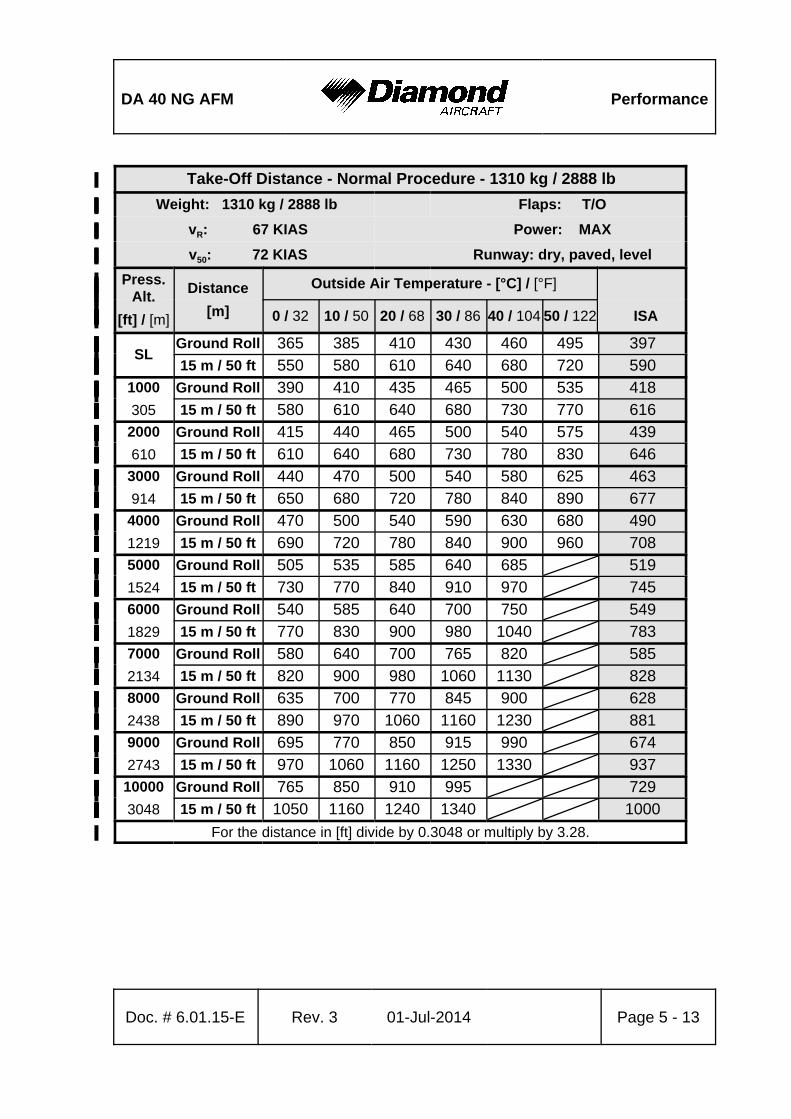
DA 40 NG AFM Performance
Doc. # 6.01.15-E Rev. 3 01-Jul-2014 Page 5 - 13
Take-Off Distance - Normal Procedure - 1310 kg / 2888 lb%
Weight: 1310 kg / 2888 lb%% Flaps: T/O%
vR: 67 KIAS%% Power: MAX%
v50: 72 KIAS%% Runway: dry, paved, level%
Press.%Alt.%
[ft] / [m]%
Distance%
[m]%
Outside Air Temperature - [°C] / [°F]%%%%
0 / 32% 10 / 50% 20 / 68% 30 / 86% 40 / 104% 50 / 122% ISA%
SL%Ground Roll% 365% 385% 410% 430% 460% 495% 397%
% 15 m / 50 ft% 550% 580% 610% 640% 680% 720% 590%
1000%
305%
Ground Roll% 390% 410% 435% 465% 500% 535% 418%%15 m / 50 ft% 580% 610% 640% 680% 730% 770% 616%
2000%
610%
Ground Roll% 415% 440% 465% 500% 540% 575% 439%%15 m / 50 ft% 610% 640% 680% 730% 780% 830% 646%
3000%
914%
Ground Roll% 440% 470% 500% 540% 580% 625% 463%%15 m / 50 ft% 650% 680% 720% 780% 840% 890% 677%
4000%
1219%
Ground Roll% 470% 500% 540% 590% 630% 680% 490%%15 m / 50 ft% 690% 720% 780% 840% 900% 960% 708%
5000%
1524%
Ground Roll% 505% 535% 585% 640% 685%% 519%%15 m / 50 ft% 730% 770% 840% 910% 970%% 745%
6000%
1829%
Ground Roll% 540% 585% 640% 700% 750%% 549%%15 m / 50 ft% 770% 830% 900% 980% 1040%% 783%
7000%
2134%
Ground Roll% 580% 640% 700% 765% 820%% 585%%15 m / 50 ft% 820% 900% 980% 1060% 1130%% 828%
8000%
2438%
Ground Roll% 635% 700% 770% 845% 900%% 628%%15 m / 50 ft% 890% 970% 1060% 1160% 1230%% 881%
9000%
2743%
Ground Roll% 695% 770% 850% 915% 990%% 674%%15 m / 50 ft% 970% 1060% 1160% 1250% 1330%% 937%
10000%
3048%
Ground Roll% 765% 850% 910% 995%%% 729%%15 m / 50 ft% 1050% 1160% 1240% 1340%%% 1000%
For the distance in [ft] divide by 0.3048 or multiply by 3.28.%
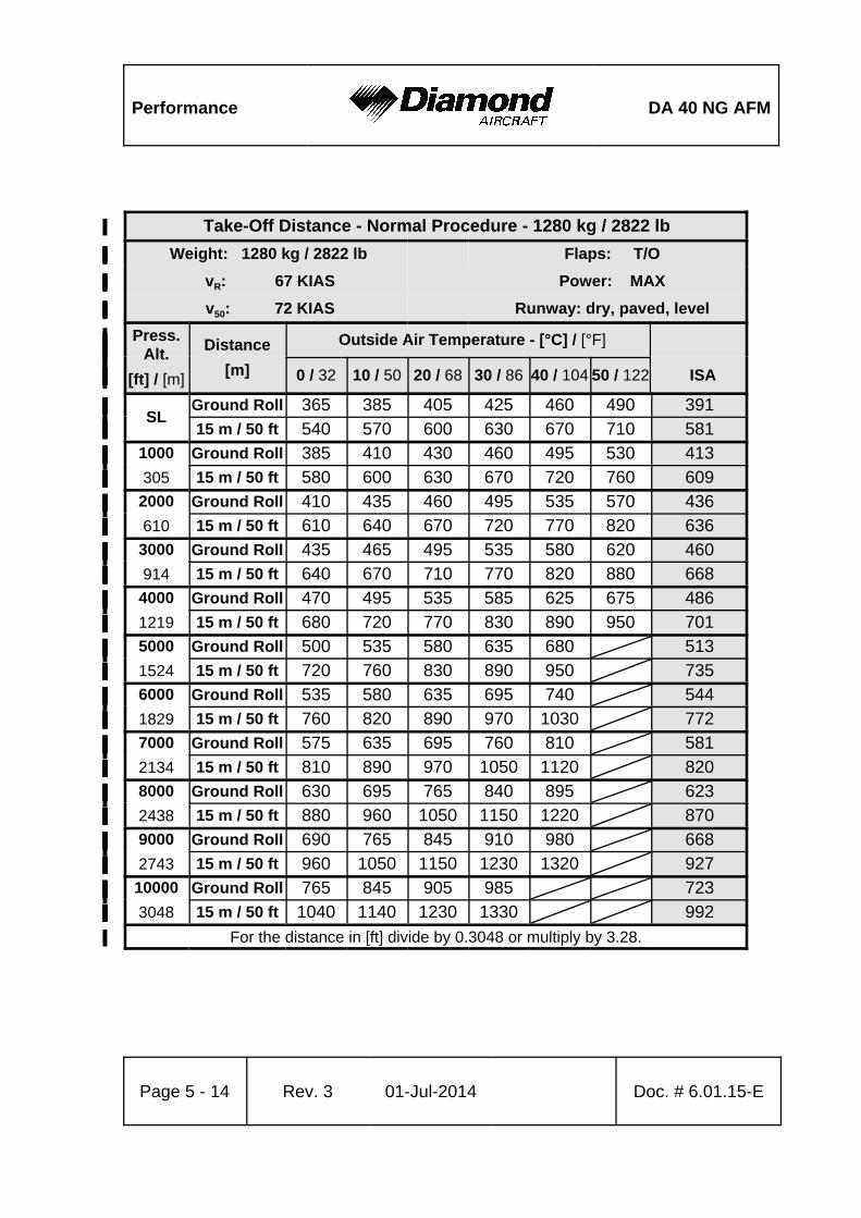
Performance DA 40 NG AFM
Page 5 - 14 Rev. 3 01-Jul-2014 Doc. # 6.01.15-E
Take-Off Distance - Normal Procedure - 1280 kg / 2822 lb%
Weight: 1280 kg / 2822 lb%% Flaps: T/O%
vR: 67 KIAS%% Power: MAX%
v50: 72 KIAS%% Runway: dry, paved, level%
Press.%Alt.%
[ft] / [m]%
Distance%
[m]%
Outside Air Temperature - [°C] / [°F]%%%%
0 / 32% 10 / 50% 20 / 68% 30 / 86% 40 / 104% 50 / 122% ISA%
SL%Ground Roll% 365% 385% 405% 425% 460% 490% 391%
% 15 m / 50 ft% 540% 570% 600% 630% 670% 710% 581%
1000%
305%
Ground Roll% 385% 410% 430% 460% 495% 530% 413%%15 m / 50 ft% 580% 600% 630% 670% 720% 760% 609%
2000%
610%
Ground Roll% 410% 435% 460% 495% 535% 570% 436%%15 m / 50 ft% 610% 640% 670% 720% 770% 820% 636%
3000%
914%
Ground Roll% 435% 465% 495% 535% 580% 620% 460%%15 m / 50 ft% 640% 670% 710% 770% 820% 880% 668%
4000%
1219%
Ground Roll% 470% 495% 535% 585% 625% 675% 486%%15 m / 50 ft% 680% 720% 770% 830% 890% 950% 701%
5000%
1524%
Ground Roll% 500% 535% 580% 635% 680%% 513%%15 m / 50 ft% 720% 760% 830% 890% 950%% 735%
6000%
1829%
Ground Roll% 535% 580% 635% 695% 740%% 544%%15 m / 50 ft% 760% 820% 890% 970% 1030%% 772%
7000%
2134%
Ground Roll% 575% 635% 695% 760% 810%% 581%%15 m / 50 ft% 810% 890% 970% 1050% 1120%% 820%
8000%
2438%
Ground Roll% 630% 695% 765% 840% 895%% 623%%15 m / 50 ft% 880% 960% 1050% 1150% 1220%% 870%
9000%
2743%
Ground Roll% 690% 765% 845% 910% 980%% 668%%15 m / 50 ft% 960% 1050% 1150% 1230% 1320%% 927%
10000%
3048%
Ground Roll% 765% 845% 905% 985%%% 723%%15 m / 50 ft% 1040% 1140% 1230% 1330%%% 992%
For the distance in [ft] divide by 0.3048 or multiply by 3.28.%
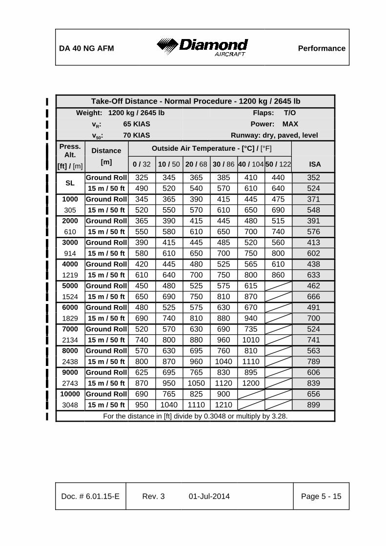
DA 40 NG AFM Performance
Doc. # 6.01.15-E Rev. 3 01-Jul-2014 Page 5 - 15
Take-Off Distance - Normal Procedure - 1200 kg / 2645 lb%
Weight: 1200 kg / 2645 lb%% Flaps: T/O%
vR: 65 KIAS%% Power: MAX%
v50: 70 KIAS%% Runway: dry, paved, level%
Press.%Alt.%
[ft] / [m]%
Distance%
[m]%
Outside Air Temperature - [°C] / [°F]%%%%
0 / 32% 10 / 50% 20 / 68% 30 / 86% 40 / 104% 50 / 122% ISA%
SL%Ground Roll% 325% 345% 365% 385% 410% 440% 352%
% 15 m / 50 ft% 490% 520% 540% 570% 610% 640% 524%
1000%
305%
Ground Roll% 345% 365% 390% 415% 445% 475% 371%%15 m / 50 ft% 520% 550% 570% 610% 650% 690% 548%
2000%
610%
Ground Roll% 365% 390% 415% 445% 480% 515% 391%%15 m / 50 ft% 550% 580% 610% 650% 700% 740% 576%
3000%
914%
Ground Roll% 390% 415% 445% 485% 520% 560% 413%%15 m / 50 ft% 580% 610% 650% 700% 750% 800% 602%
4000%
1219%
Ground Roll% 420% 445% 480% 525% 565% 610% 438%%15 m / 50 ft% 610% 640% 700% 750% 800% 860% 633%
5000%
1524%
Ground Roll% 450% 480% 525% 575% 615%% 462%%15 m / 50 ft% 650% 690% 750% 810% 870%% 666%
6000%
1829%
Ground Roll% 480% 525% 575% 630% 670%% 491%%15 m / 50 ft% 690% 740% 810% 880% 940%% 700%
7000%
2134%
Ground Roll% 520% 570% 630% 690% 735%% 524%%15 m / 50 ft% 740% 800% 880% 960% 1010%% 741%
8000%
2438%
Ground Roll% 570% 630% 695% 760% 810%% 563%%15 m / 50 ft% 800% 870% 960% 1040% 1110%% 789%
9000%
2743%
Ground Roll% 625% 695% 765% 830% 895%% 606%%15 m / 50 ft% 870% 950% 1050% 1120% 1200%% 839%
10000%
3048%
Ground Roll% 690% 765% 825% 900%%% 656%%15 m / 50 ft% 950% 1040% 1110% 1210%%% 899%
For the distance in [ft] divide by 0.3048 or multiply by 3.28.%
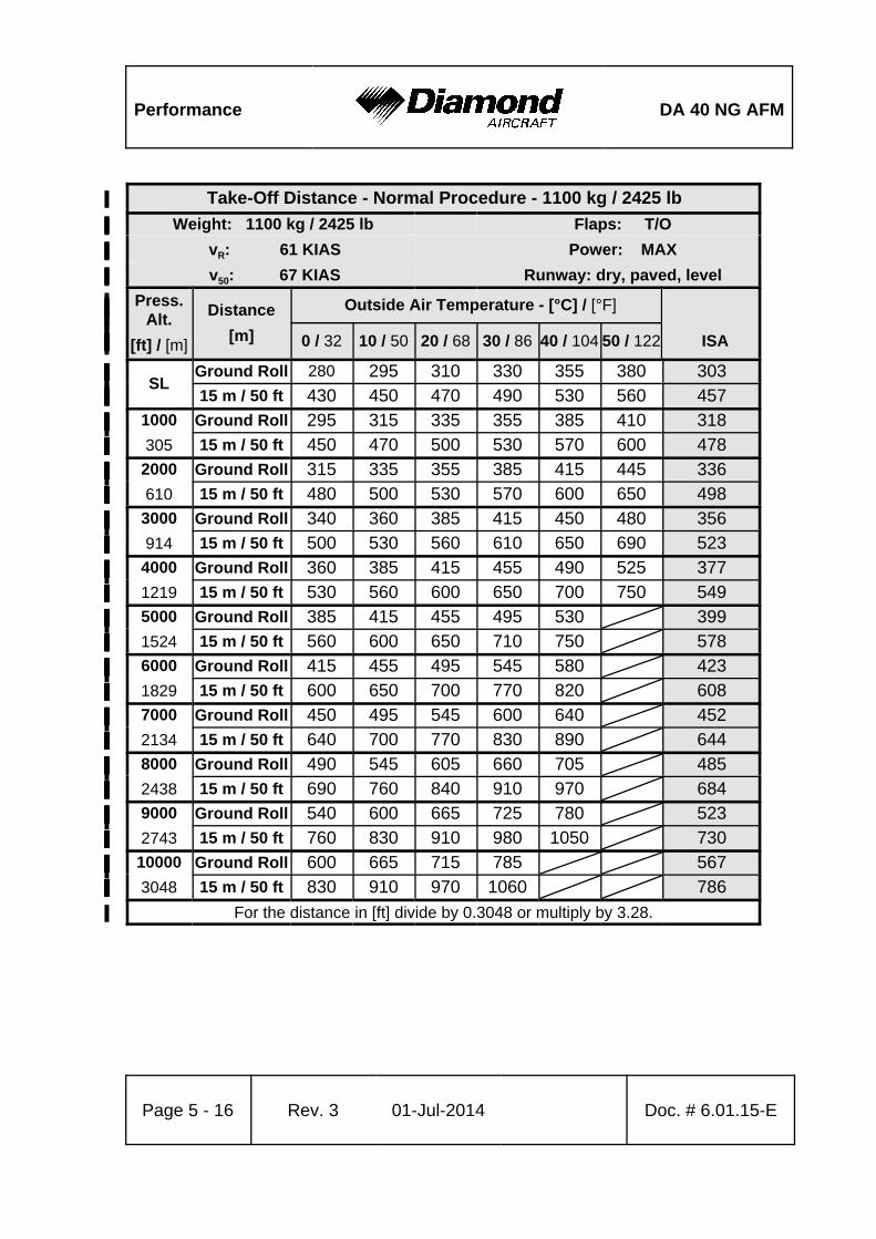
Performance DA 40 NG AFM
Page 5 - 16 Rev. 3 01-Jul-2014 Doc. # 6.01.15-E
Take-Off Distance - Normal Procedure - 1100 kg / 2425 lb%
Weight: 1100 kg / 2425 lb%% Flaps: T/O%
vR: 61 KIAS%% Power: MAX%
v50: 67 KIAS%% Runway: dry, paved, level%
Press.%Alt.%
[ft] / [m]%
Distance%
[m]%
Outside Air Temperature - [°C] / [°F]%%%%
0 / 32% 10 / 50% 20 / 68% 30 / 86% 40 / 104% 50 / 122% ISA%
SL%Ground Roll% 280% 295% 310% 330% 355% 380% 303%
% 15 m / 50 ft% 430% 450% 470% 490% 530% 560% 457%
1000%
305%
Ground Roll% 295% 315% 335% 355% 385% 410% 318%%15 m / 50 ft% 450% 470% 500% 530% 570% 600% 478%
2000%
610%
Ground Roll% 315% 335% 355% 385% 415% 445% 336%%15 m / 50 ft% 480% 500% 530% 570% 600% 650% 498%
3000%
914%
Ground Roll% 340% 360% 385% 415% 450% 480% 356%%15 m / 50 ft% 500% 530% 560% 610% 650% 690% 523%
4000%
1219%
Ground Roll% 360% 385% 415% 455% 490% 525% 377%%15 m / 50 ft% 530% 560% 600% 650% 700% 750% 549%
5000%
1524%
Ground Roll% 385% 415% 455% 495% 530%% 399%%15 m / 50 ft% 560% 600% 650% 710% 750%% 578%
6000%
1829%
Ground Roll% 415% 455% 495% 545% 580%% 423%%15 m / 50 ft% 600% 650% 700% 770% 820%% 608%
7000%
2134%
Ground Roll% 450% 495% 545% 600% 640%% 452%%15 m / 50 ft% 640% 700% 770% 830% 890%% 644%
8000%
2438%
Ground Roll% 490% 545% 605% 660% 705%% 485%%15 m / 50 ft% 690% 760% 840% 910% 970%% 684%
9000%
2743%
Ground Roll% 540% 600% 665% 725% 780%% 523%%15 m / 50 ft% 760% 830% 910% 980% 1050%% 730%
10000%
3048%
Ground Roll% 600% 665% 715% 785%%% 567%%15 m / 50 ft% 830% 910% 970% 1060%%% 786%
For the distance in [ft] divide by 0.3048 or multiply by 3.28.%
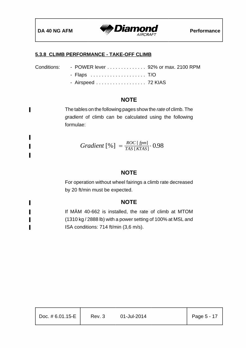
DA 40 NG AFM Performance
Doc. # 6.01.15-E Rev. 3 01-Jul-2014 Page 5 - 17
Gradient ROC fpmTAS KTAS
[%] .[ ][ ] 0 98
5.3.8 CLIMB PERFORMANCE - TAKE-OFF CLIMB
Conditions: - POWER lever . . . . . . . . . . . . . . 92% or max. 2100 RPM
- Flaps . . . . . . . . . . . . . . . . . . . . T/O
- Airspeed . . . . . . . . . . . . . . . . . . 72 KIAS
NOTE
The tables on the following pages show the rate of climb. The%
gradient of climb can be calculated using the following
formulae:
%
%
%
NOTE
For operation without wheel fairings a climb rate decreased
by 20 ft/min must be expected.
NOTE%
If MÄM 40-662 is installed, the rate of climb at MTOM%
(1310 kg / 2888 lb) with a power setting of 100% at MSL and%
ISA conditions: 714 ft/min (3,6 m/s). %
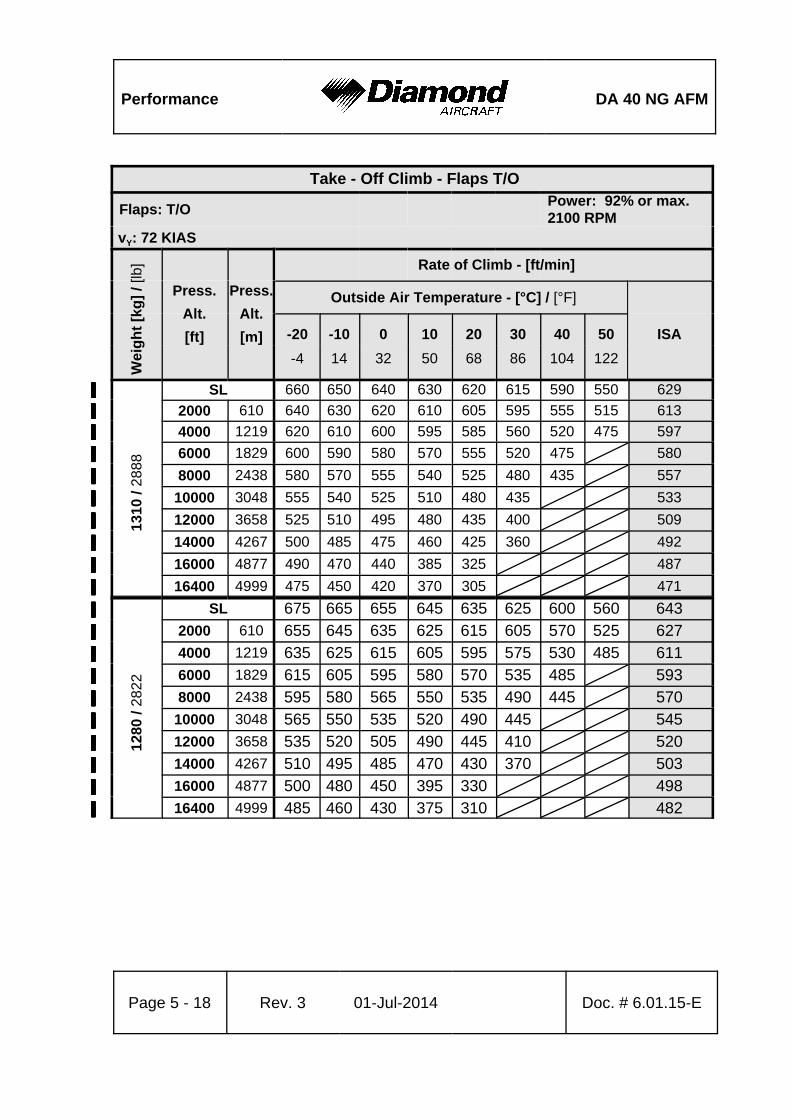
Performance DA 40 NG AFM
Page 5 - 18 Rev. 3 01-Jul-2014 Doc. # 6.01.15-E
Take - Off Climb - Flaps T/O
Flaps: T/OPower: 92% or max.2100 RPM
vY: 72 KIAS
Wei
gh
t [k
g]
/ [lb
]
Press.
Alt.
[ft]
Press.
Alt.
[m]
Rate of Climb - [ft/min]
Outside Air Temperature - [°C] / [°F]
-20 -10 0 10 20 30 40 50 ISA
-4 14 32 50 68 86 104 122
1310
/ 2
888
SL 660% 650% 640% 630% 620% 615% 590% 550% 629%
2000 610 640% 630% 620% 610% 605% 595% 555% 515% 613%
4000 1219 620% 610% 600% 595% 585% 560% 520% 475% 597%
6000 1829 600% 590% 580% 570% 555% 520% 475%% 580%
8000 2438 580% 570% 555% 540% 525% 480% 435%% 557%
10000 3048 555% 540% 525% 510% 480% 435%%% 533%
12000 3658 525% 510% 495% 480% 435% 400%%% 509%
14000 4267 500% 485% 475% 460% 425% 360%%% 492%
16000 4877 490% 470% 440% 385% 325%%%% 487%
16400 4999 475% 450% 420% 370% 305%%%% 471%
1280
/ 28
22
SL 675% 665% 655% 645% 635% 625% 600% 560% 643%
2000 610 655% 645% 635% 625% 615% 605% 570% 525% 627%
4000 1219 635% 625% 615% 605% 595% 575% 530% 485% 611%
6000 1829 615% 605% 595% 580% 570% 535% 485%% 593%
8000 2438 595% 580% 565% 550% 535% 490% 445%% 570%
10000 3048 565% 550% 535% 520% 490% 445%%% 545%
12000 3658 535% 520% 505% 490% 445% 410%%% 520%
14000 4267 510% 495% 485% 470% 430% 370%%% 503%
16000 4877 500% 480% 450% 395% 330%%%% 498%
16400 4999 485% 460% 430% 375% 310%%%% 482%
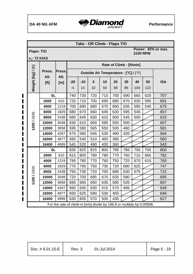
DA 40 NG AFM Performance
Take - Off Climb - Flaps T/O
Flaps: T/OPower: 92% or max.2100 RPM
vY: 72 KIAS
Wei
gh
t [k
g]
/ [lb
]
Press.
Alt.
[ft]
Press.
Alt.
[m]
Rate of Climb - [ft/min]
Outside Air Temperature - [°C] / [°F]
-20 -10 0 10 20 30 40 50 ISA
-4 14 32 50 68 86 104 122
Doc. # 6.01.15-E Rev. 3 01-Jul-2014 Page 5 - 19
1200
/ 26
45
SL 740% 730% 720% 710% 700% 690% 665% 620% 707%
2000 610 720% 710% 700% 690% 680% 670% 630% 585% 691%
4000 1219 700% 690% 680% 670% 660% 635% 590% 540% 675%
6000 1829 680% 670% 660% 645% 630% 595% 545%% 657%
8000 2438 660% 645% 630% 615% 600% 545% 500%% 633%
10000 3048 630% 615% 600% 585% 550% 500%%% 607%
12000 3658 595% 580% 565% 550% 505% 460%%% 581%
14000 4267 575% 560% 545% 530% 490% 420%%% 564%
16000 4877 560% 540% 510% 450% 380%%%% 560%
16400 4999 545% 520% 490% 430% 360%%%% 543%
1100
/ 24
25
SL 835% 825% 815% 800% 795% 785% 755% 705% 800%
2000 610 815% 805% 790% 780% 770% 760% 715% 665% 782%
4000 1219 795% 780% 770% 760% 750% 725% 670% 615% 765%
6000 1829 770% 760% 750% 735% 720% 680% 625%% 747%
8000 2438 750% 735% 720% 705% 685% 630% 575%% 722%
10000 3048 720% 700% 685% 670% 635% 580%%% 695%
12000 3658 685% 665% 650% 635% 585% 535%%% 667%
14000 4267 660% 645% 630% 615% 570% 495%%% 649%
16000 4877 650% 625% 590% 530% 455%%%% 646%
16400 4999 630% 605% 570% 505% 430%%%% 627%
For the rate of climb in [m/s] divide by 196.8 or multiply by 0.00508.

Performance DA 40 NG AFM
Page 5 - 20 Rev. 3 01-Jul-2014 Doc. # 6.01.15-E
Gradient ROC fpmTAS KTAS
[%] .[ ][ ] 0 98
5.3.9 CLIMB PERFORMANCE - CRUISE CLIMB
Conditions: - POWER lever . . . . . . . . . . . . . . 92% or max. 2100 RPM
- Flaps . . . . . . . . . . . . . . . . . . . . UP
- Airspeed . . . . . . . . . . . . . . . . . . 88 KIAS
NOTE
The graph on the following page shows the rate of climb. The
gradient of climb cannot easily be determined with a graph,
but it can be calculated using the following formulae:
%
%
%
NOTE
For operation without wheel fairings a climb rate decreased
by 40 ft/min must be expected.
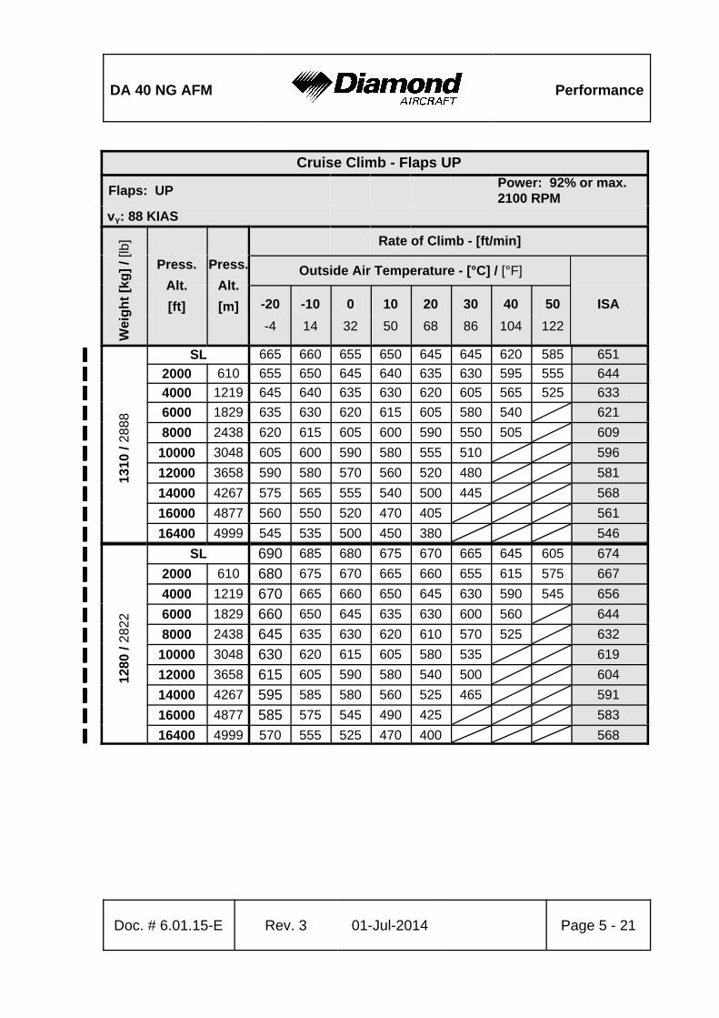
DA 40 NG AFM Performance
Doc. # 6.01.15-E Rev. 3 01-Jul-2014 Page 5 - 21
Cruise Climb - Flaps UP
Flaps: UPPower: 92% or max.2100 RPM
vY: 88 KIAS
Wei
gh
t [k
g]
/ [lb
]
Press.
Alt.
[ft]
Press.
Alt.
[m]
Rate of Climb - [ft/min]
Outside Air Temperature - [°C] / [°F]
-20 -10 0 10 20 30 40 50 ISA
-4 14 32 50 68 86 104 122
1310
/ 2
888
SL 665% 660% 655% 650% 645% 645% 620% 585% 651%
2000 610 655% 650% 645% 640% 635% 630% 595% 555% 644%
4000 1219 645% 640% 635% 630% 620% 605% 565% 525% 633%
6000 1829 635% 630% 620% 615% 605% 580% 540%% 621%
8000 2438 620% 615% 605% 600% 590% 550% 505%% 609%
10000 3048 605% 600% 590% 580% 555% 510%%% 596%
12000 3658 590% 580% 570% 560% 520% 480%%% 581%
14000 4267 575% 565% 555% 540% 500% 445%%% 568%
16000 4877 560% 550% 520% 470% 405%%%% 561%
16400 4999 545% 535% 500% 450% 380%%%% 546%
1280
/ 28
22
SL 690% 685% 680% 675% 670% 665% 645% 605% 674%
2000 610 680% 675% 670% 665% 660% 655% 615% 575% 667%
4000 1219 670% 665% 660% 650% 645% 630% 590% 545% 656%
6000 1829 660% 650% 645% 635% 630% 600% 560%% 644%
8000 2438 645% 635% 630% 620% 610% 570% 525%% 632%
10000 3048 630% 620% 615% 605% 580% 535%%% 619%
12000 3658 615% 605% 590% 580% 540% 500%%% 604%
14000 4267 595% 585% 580% 560% 525% 465%%% 591%
16000 4877 585% 575% 545% 490% 425%%%% 583%
16400 4999 570% 555% 525% 470% 400%%%% 568%
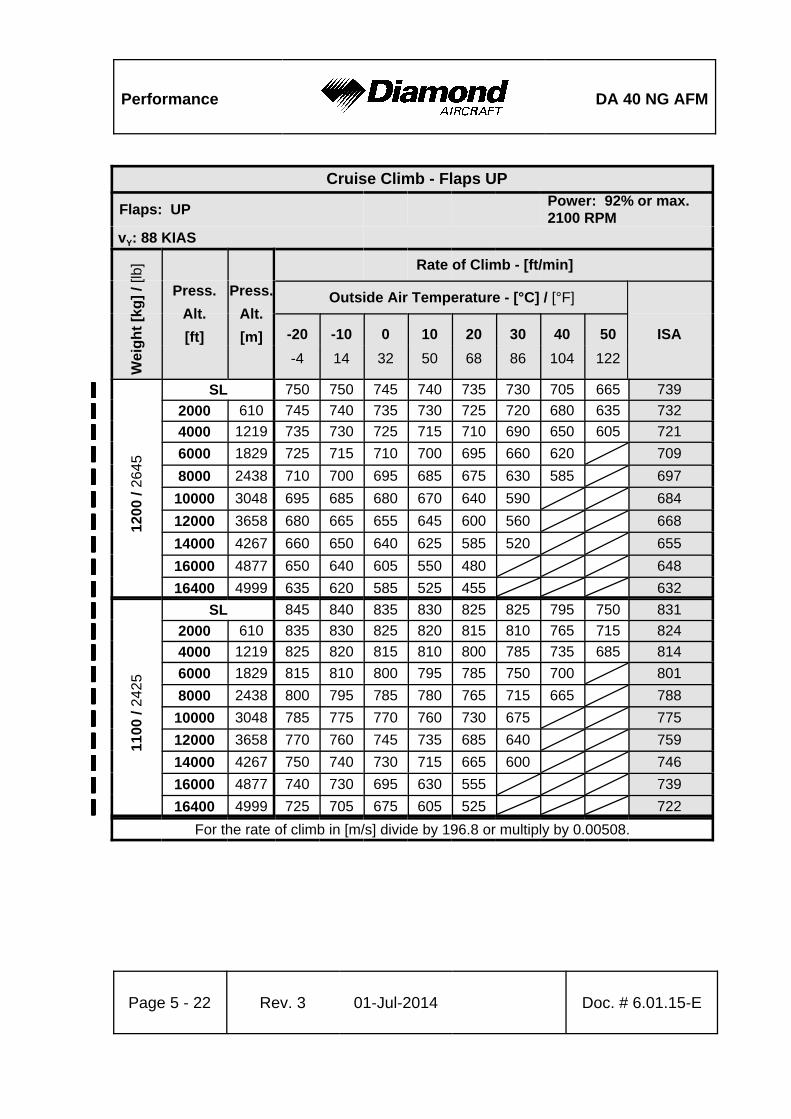
Performance DA 40 NG AFM
Cruise Climb - Flaps UP
Flaps: UPPower: 92% or max.2100 RPM
vY: 88 KIAS
Wei
gh
t [k
g]
/ [lb
]
Press.
Alt.
[ft]
Press.
Alt.
[m]
Rate of Climb - [ft/min]
Outside Air Temperature - [°C] / [°F]
-20 -10 0 10 20 30 40 50 ISA
-4 14 32 50 68 86 104 122
Page 5 - 22 Rev. 3 01-Jul-2014 Doc. # 6.01.15-E
1200
/ 26
45
SL 750% 750% 745% 740% 735% 730% 705% 665% 739%
2000 610 745% 740% 735% 730% 725% 720% 680% 635% 732%
4000 1219 735% 730% 725% 715% 710% 690% 650% 605% 721%
6000 1829 725% 715% 710% 700% 695% 660% 620%% 709%
8000 2438 710% 700% 695% 685% 675% 630% 585%% 697%
10000 3048 695% 685% 680% 670% 640% 590%%% 684%
12000 3658 680% 665% 655% 645% 600% 560%%% 668%
14000 4267 660% 650% 640% 625% 585% 520%%% 655%
16000 4877 650% 640% 605% 550% 480%%%% 648%
16400 4999 635% 620% 585% 525% 455%%%% 632%
1100
/ 24
25
SL 845% 840% 835% 830% 825% 825% 795% 750% 831%
2000 610 835% 830% 825% 820% 815% 810% 765% 715% 824%
4000 1219 825% 820% 815% 810% 800% 785% 735% 685% 814%
6000 1829 815% 810% 800% 795% 785% 750% 700%% 801%
8000 2438 800% 795% 785% 780% 765% 715% 665%% 788%
10000 3048 785% 775% 770% 760% 730% 675%%% 775%
12000 3658 770% 760% 745% 735% 685% 640%%% 759%
14000 4267 750% 740% 730% 715% 665% 600%%% 746%
16000 4877 740% 730% 695% 630% 555%%%% 739%
16400 4999 725% 705% 675% 605% 525%%%% 722%
For the rate of climb in [m/s] divide by 196.8 or multiply by 0.00508.
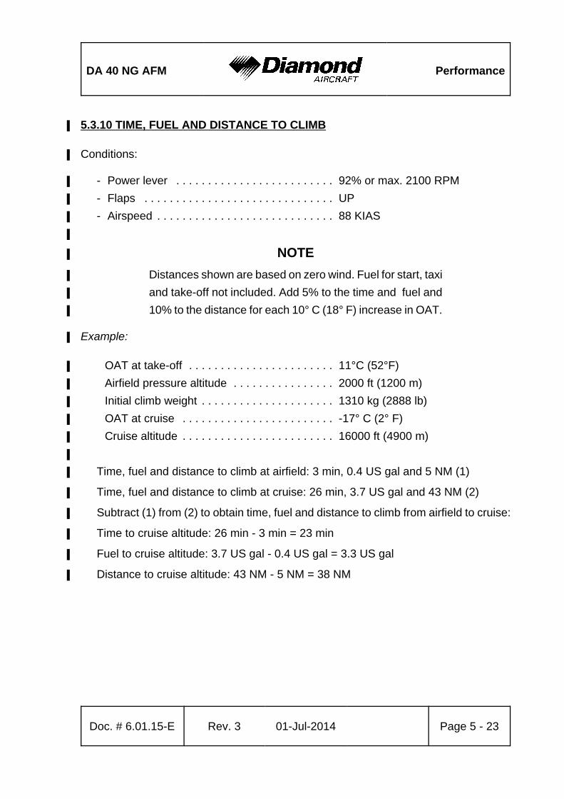
DA 40 NG AFM Performance
Doc. # 6.01.15-E Rev. 3 01-Jul-2014 Page 5 - 23
5.3.10 TIME, FUEL AND DISTANCE TO CLIMB%
Conditions:%
- Power lever . . . . . . . . . . . . . . . . . . . . . . . . . 92% or max. 2100 RPM%
- Flaps . . . . . . . . . . . . . . . . . . . . . . . . . . . . . . UP%
- Airspeed . . . . . . . . . . . . . . . . . . . . . . . . . . . . 88 KIAS%
%
NOTE%
Distances shown are based on zero wind. Fuel for start, taxi%
and take-off not included. Add 5% to the time and fuel and%
10% to the distance for each 10° C (18° F) increase in OAT.%
Example:%
OAT at take-off . . . . . . . . . . . . . . . . . . . . . . . 11°C (52°F)%
Airfield pressure altitude . . . . . . . . . . . . . . . . 2000 ft (1200 m)%
Initial climb weight . . . . . . . . . . . . . . . . . . . . . 1310 kg (2888 lb)%
OAT at cruise . . . . . . . . . . . . . . . . . . . . . . . . -17° C (2° F)%
Cruise altitude . . . . . . . . . . . . . . . . . . . . . . . . 16000 ft (4900 m)%
%
Time, fuel and distance to climb at airfield: 3 min, 0.4 US gal and 5 NM (1)%
Time, fuel and distance to climb at cruise: 26 min, 3.7 US gal and 43 NM (2)%
Subtract (1) from (2) to obtain time, fuel and distance to climb from airfield to cruise:%
Time to cruise altitude: 26 min - 3 min = 23 min%
Fuel to cruise altitude: 3.7 US gal - 0.4 US gal = 3.3 US gal%
Distance to cruise altitude: 43 NM - 5 NM = 38 NM%
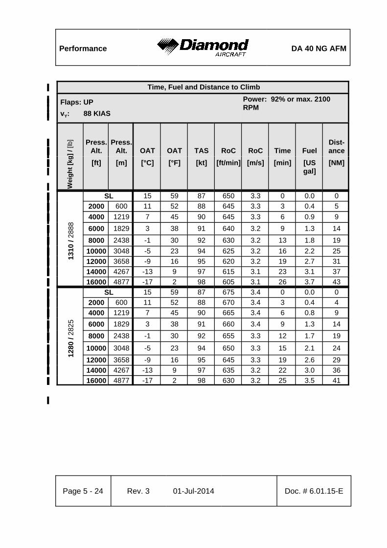
Performance DA 40 NG AFM
Page 5 - 24 Rev. 3 01-Jul-2014 Doc. # 6.01.15-E
Time, Fuel and Distance to Climb%
Flaps: UP%
vY: 88 KIAS%
Power: 92% or max. 2100%RPM%
%
% Wei
gh
t [k
g]
/ [lb
] Press.%Alt.%
Press.%Alt.% OAT% OAT% TAS% RoC% RoC% Time% Fuel%
Dist-%ance%%
[ft]% [m]% [°C]% [°F]% [kt]% [ft/min]% [m/s]% [min]% [US%gal]%
[NM]%
% 1310
/ 2
888
SL% 15% 59% 87% 650% 3.3% 0% 0.0% 0%%2000% 600% 11% 52% 88% 645% 3.3% 3% 0.4% 5%%4000% 1219% 7% 45% 90% 645% 3.3% 6% 0.9% 9%%6000% 1829% 3% 38% 91% 640% 3.2% 9% 1.3% 14%%8000% 2438% -1% 30% 92% 630% 3.2% 13% 1.8% 19%%
10000% 3048% -5% 23% 94% 625% 3.2% 16% 2.2% 25%%12000% 3658% -9% 16% 95% 620% 3.2% 19% 2.7% 31%%14000% 4267% -13% 9% 97% 615% 3.1% 23% 3.1% 37%
%
16000% 4877% -17% 2% 98% 605% 3.1% 26% 3.7% 43%
% 1280
/ 28
25
SL% 15% 59% 87% 675% 3.4% 0% 0.0% 0%%2000% 600% 11% 52% 88% 670% 3.4% 3% 0.4% 4%%4000% 1219% 7% 45% 90% 665% 3.4% 6% 0.8% 9%%6000% 1829% 3% 38% 91% 660% 3.4% 9% 1.3% 14%%8000% 2438% -1% 30% 92% 655% 3.3% 12% 1.7% 19%%
10000% 3048% -5% 23% 94% 650% 3.3% 15% 2.1% 24%%
12000% 3658% -9% 16% 95% 645% 3.3% 19% 2.6% 29%%14000% 4267% -13% 9% 97% 635% 3.2% 22% 3.0% 36%
%
16000% 4877% -17% 2% 98% 630% 3.2% 25% 3.5% 41%
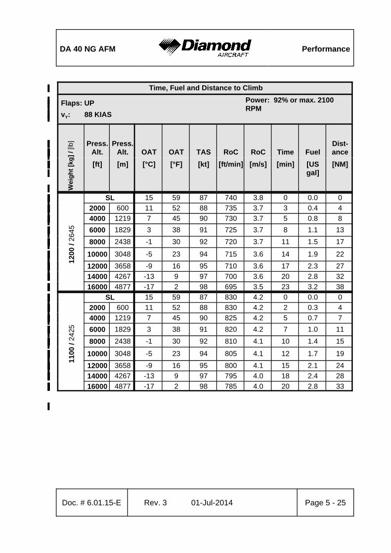
DA 40 NG AFM Performance
Time, Fuel and Distance to Climb%
Flaps: UP%
vY: 88 KIAS%
Power: 92% or max. 2100%RPM%
%
% Wei
gh
t [k
g]
/ [lb
] Press.%Alt.%
Press.%Alt.% OAT% OAT% TAS% RoC% RoC% Time% Fuel%
Dist-%ance%%
[ft]% [m]% [°C]% [°F]% [kt]% [ft/min]% [m/s]% [min]% [US%gal]%
[NM]%
Doc. # 6.01.15-E Rev. 3 01-Jul-2014 Page 5 - 25
% 1200
/ 26
45
SL% 15% 59% 87% 740% 3.8% 0% 0.0% 0%%2000% 600% 11% 52% 88% 735% 3.7% 3% 0.4% 4%%4000% 1219% 7% 45% 90% 730% 3.7% 5% 0.8% 8%%6000% 1829% 3% 38% 91% 725% 3.7% 8% 1.1% 13%%8000% 2438% -1% 30% 92% 720% 3.7% 11% 1.5% 17%%
10000% 3048% -5% 23% 94% 715% 3.6% 14% 1.9% 22%%
12000% 3658% -9% 16% 95% 710% 3.6% 17% 2.3% 27%%14000% 4267% -13% 9% 97% 700% 3.6% 20% 2.8% 32%
%
16000% 4877% -17% 2% 98% 695% 3.5% 23% 3.2% 38%
% 1100
/ 24
25
SL% 15% 59% 87% 830% 4.2% 0% 0.0% 0%%2000% 600% 11% 52% 88% 830% 4.2% 2% 0.3% 4%%4000% 1219% 7% 45% 90% 825% 4.2% 5% 0.7% 7%%6000% 1829% 3% 38% 91% 820% 4.2% 7% 1.0% 11%%8000% 2438% -1% 30% 92% 810% 4.1% 10% 1.4% 15%%
10000% 3048% -5% 23% 94% 805% 4.1% 12% 1.7% 19%%
12000% 3658% -9% 16% 95% 800% 4.1% 15% 2.1% 24%%14000% 4267% -13% 9% 97% 795% 4.0% 18% 2.4% 28%
%
16000% 4877% -17% 2% 98% 785% 4.0% 20% 2.8% 33%
Performance DA 40 NG AFM
Page 5 - 26 Rev. 3 01-Jul-2014 Doc. # 6.01.15-E
5.3.11 CRUISE PERFORMANCE%
NOTE
For operation without wheel fairings a performance reduction
of 4% TAS at all power settings must be expected.
Conditions:%
- Flaps . . . . . . . . . . . . . . . . . . . . . . . . . . . . . . UP%
- Landing gear . . . . . . . . . . . . . . . . . . . . . . . . retracted%
- Weight . . . . . . . . . . . . . . . . . . . . . . . . . . . . . 1310 kg (2888 lb)%
%
For conversion of OAT to delta-ISA temperatures refer to Chapter 5.3.3 - INTERNATIONAL%
STANDARD ATMOSPHERE. %
%
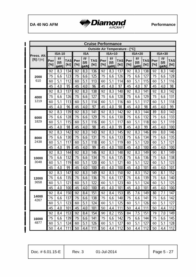
DA 40 NG AFM Performance
Doc. # 6.01.15-E Rev. 3 01-Jul-2014 Page 5 - 27
Cruise Performance%
Press. Alt.%[ft] / [m]%
Outside Air Temperature - [°C]%%ISA-10% ISA% ISA+10% ISA+20% ISA+30%
% Pwr%[%]%
FF%[US%
gal/h]%
TAS%[kt]%
Pwr%[%]%
FF%[US%
gal/h]%
TAS%[kt]%
Pwr%[%]%
FF%[US%
gal/h]%
TAS%[kt]%
Pwr%[%]%
FF%[US%
gal/h]%
TAS%[kt]%
Pwr%[%]%
FF%[US%
gal/h]%
TAS%[kt]%
2000%610%
92% 8.3% 134% 92% 8.3% 136% 92% 8.3% 137% 92% 8.3% 138% 92% 8.3% 140%%75% 6.6% 123% 75% 6.6% 125% 75% 6.6% 126% 75% 6.6% 127% 75% 6.6% 128%%60% 5.1% 112% 60% 5.1% 113% 60% 5.1% 114% 60% 5.1% 115% 60% 5.1% 116%
%45% 4.0% 95% 45% 4.0% 96% 45% 4.0% 97% 45% 4.0% 97% 45% 4.0% 98%
4000%1219%
92% 8.3% 137% 92% 8.3% 138% 92% 8.3% 140% 92% 8.3% 141% 92% 8.3% 142%%75% 6.6% 126% 75% 6.6% 127% 75% 6.6% 128% 75% 6.6% 129% 75% 6.6% 131%%60% 5.1% 113% 60% 5.1% 114% 60% 5.1% 116% 60% 5.1% 117% 60% 5.1% 118%
%45% 4.0% 96% 45% 4.0% 97% 45% 4.0% 98% 45% 4.0% 98% 45% 4.0% 99%
6000%1829%
92% 8.3% 139% 92% 8.3% 141% 92% 8.3% 142% 92% 8.3% 144% 89% 8.0% 143%%75% 6.6% 128% 75% 6.6% 129% 75% 6.6% 130% 75% 6.6% 132% 75% 6.6% 133%%60% 5.1% 115% 60% 5.1% 116% 60% 5.1% 117% 60% 5.1% 118% 60% 5.1% 119%
%45% 4.0% 98% 45% 4.0% 98% 45% 4.0% 99% 45% 4.0% 99% 45% 4.0% 100%
8000%2438%
92% 8.3% 142% 92% 8.3% 143% 92% 8.3% 145% 92% 8.3% 146% 89% 8.0% 146%%75% 6.6% 130% 75% 6.6% 131% 75% 6.6% 133% 75% 6.6% 134% 75% 6.6% 135%%60% 5.1% 117% 60% 5.1% 118% 60% 5.1% 119% 60% 5.1% 120% 60% 5.1% 121%
%45% 4.0% 99% 45% 4.0% 99% 45% 4.0% 100% 45% 4.0% 100% 45% 4.0% 100%
10000%3048%
92% 8.3% 144% 92% 8.3% 146% 92% 8.3% 148% 92% 8.3% 149% 90% 8.1% 149%%75% 6.6% 132% 75% 6.6% 134% 75% 6.6% 135% 75% 6.6% 136% 75% 6.6% 138%%60% 5.1% 119% 60% 5.1% 120% 60% 5.1% 121% 60% 5.1% 122% 60% 5.1% 123%
%45% 4.0% 99% 45% 4.0% 100% 45% 4.0% 100% 45% 4.0% 101% 45% 4.0% 101%
12000%3658%
92% 8.3% 147% 92% 8.3% 149% 92% 8.3% 150% 92% 8.3% 152% 90% 8.1% 152%%75% 6.6% 135% 75% 6.6% 136% 75% 6.6% 137% 75% 6.6% 139% 75% 6.6% 140%%60% 5.1% 121% 60% 5.1% 122% 60% 5.1% 123% 60% 5.1% 124% 60% 5.1% 125%
%45% 4.0% 100% 45% 4.0% 100% 45% 4.0% 101% 45% 4.0% 101% 45% 4.0% 100%
14000%4267%
%
92% 8.4% 150% 92% 8.4% 151% 92% 8.4% 153% 85% 7.6% 149% 80% 7.1% 147%%75% 6.6% 137% 75% 6.6% 138% 75% 6.6% 140% 75% 6.6% 141% 75% 6.6% 142%%60% 5.1% 123% 60% 5.1% 124% 60% 5.1% 125% 60% 5.1% 126% 60% 5.1% 127%
% 45% 4.0% 101% 45% 4.0% 101% 50% 4.4% 111% 50% 4.4% 111% 50% 4.4% 112%
16000%4877%
92% 8.4% 153% 92% 8.4% 154% 90% 8.2% 155% 84% 7.5% 151% 79% 7.0% 149%%75% 6.6% 139% 75% 6.6% 141% 75% 6.6% 142% 75% 6.6% 144% 75% 6.6% 145%%60% 5.1% 124% 60% 5.1% 126% 60% 5.1% 127% 60% 5.1% 127% 60% 5.1% 128%
%50% 4.4% 111% 50% 4.4% 111% 50% 4.4% 112% 50% 4.4% 112% 50% 4.4% 112%
Performance DA 40 NG AFM
Page 5 - 28 Rev. 3 01-Jul-2014 Doc. # 6.01.15-E
5.3.12 LANDING DISTANCES%
Conditions:%
- Power lever . . . . . . . . . . . . . . . . . . . . . . . . IDLE%
- Flaps . . . . . . . . . . . . . . . . . . . . . . . . . . . . . LDG, T/O or UP%
- Runway . . . . . . . . . . . . . . . . . . . . . . . . . . . dry, paved, level%
- Approach speed . . . . . . . . . . . . . . . . . . . . . vREF%
%
The following factors are to be applied to the computed landing distance for the noted%
condition:%
- Headwind: Decrease by 10% for each 20 kt%
(10.3 m/s) headwind.%
- Tailwind: Increase by 10% for each 3 kt%
(1.5 m/s) tailwind.%
- Paved runway, wet: Increase by 15%.%
- Grass runway, dry, 5 cm (2 in) long: Increase the ground roll by 30%.%
- Grass runway, dry, longer than 5 cm (2 in):%
Increase the ground roll at least by%
45 %.%
- Grass runway, wet or soft runway: Increase the ground roll by 15%.%
- Downhill slope: Increase the ground roll by 10% for%
each 1% (1 m per 100 m or 1 ft per%
100 ft) slope.%
WARNING%
For a safe landing the available runway length must be at%
least equal to the landing distance over a 50 ft (15 m)%
obstacle.%
DA 40 NG AFM Performance
Doc. # 6.01.15-E Rev. 3 01-Jul-2014 Page 5 - 29
WARNING
Poor maintenance condition of the airplane, deviation from
the given procedures, uneven runway, as well as unfavorable
external factors (rain, unfavorable wind conditions, including
cross-wind) will increase the landing distance.
CAUTION%
The factors in the above corrections are typical values. On%
wet ground or wet soft grass covered runways the landing%
distance may become significantly longer than stated above.%
In any case the pilot must allow for the condition of the runway%
to ensure a safe landing.%
The above corrections for runway slope should be used with%
caution since published runway slope data is usually the net%
slope from one end of the runway to the other. Runways may%
have positions at their length at greater or lesser slopes than%
published slope, lengthening (or shortening) the landing roll%
estimated with these tables. %
NOTE%
The effect of 50% of the headwind component and 150% of%
the tailwind component is already incorporated in the head-%
and tailwind factors.%
NOTE
Higher approach speeds result in a significant longer landing
distance during flare.
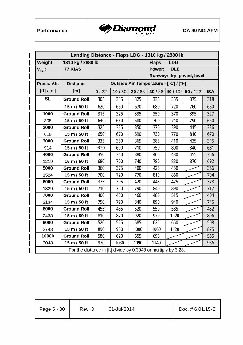
Performance DA 40 NG AFM
Page 5 - 30 Rev. 3 01-Jul-2014 Doc. # 6.01.15-E
Landing Distance - Flaps LDG - 1310 kg / 2888 lb%
Weight:% 1310 kg / 2888 lb%% Flaps: LDG%
vREF:% 77 KIAS%% Power: IDLE%
%%% Runway: dry, paved, level%
Press. Alt.%
[ft] / [m]%
Distance%
[m]%
Outside Air Temperature - [°C] / [°F]%%%%
0 / 32% 10 / 50% 20 / 68% 30 / 86% 40 / 104% 50 / 122% ISA%
SL%
%
Ground Roll% 305% 315% 325% 335% 355% 375% 318%%15 m / 50 ft% 620% 650% 670% 680% 720% 760% 650%
1000%
305%
Ground Roll% 315% 325% 335% 350% 370% 395% 327%%15 m / 50 ft% 640% 660% 680% 700% 740% 790% 660%
2000%
610%
Ground Roll% 325% 335% 350% 370% 390% 415% 336%%15 m / 50 ft% 650% 670% 690% 730% 770% 810% 670%
3000%
914%
Ground Roll% 335% 350% 365% 385% 410% 435% 345%%15 m / 50 ft% 670% 690% 710% 750% 800% 840% 681%
4000%
1219%
Ground Roll% 350% 360% 380% 405% 430% 455% 356%%15 m / 50 ft% 680% 700% 740% 780% 830% 870% 692%
5000%
1524%
Ground Roll% 360% 375% 400% 425% 450%% 366%%15 m / 50 ft% 700% 720% 770% 810% 860%% 704%
6000%
1829%
Ground Roll% 375% 395% 420% 445% 475%% 378%%15 m / 50 ft% 710% 750% 790% 840% 890%% 717%
7000%
2134%
Ground Roll% 400% 430% 460% 485% 515%% 404%%15 m / 50 ft% 750% 790% 840% 890% 940%% 746%
8000%
2438%
Ground Roll% 455% 485% 520% 550% 585%% 452%%15 m / 50 ft% 810% 870% 920% 970% 1020%% 806%
9000%
2743%
Ground Roll% 520% 555% 585% 625% 660%% 508%%15 m / 50 ft% 890% 950% 1000% 1060% 1120%% 875%
10000%
3048%
Ground Roll% 580% 620% 655% 695%%% 565%%15 m / 50 ft% 970% 1030% 1090% 1140%%% 936%
For the distance in [ft] divide by 0.3048 or multiply by 3.28.%
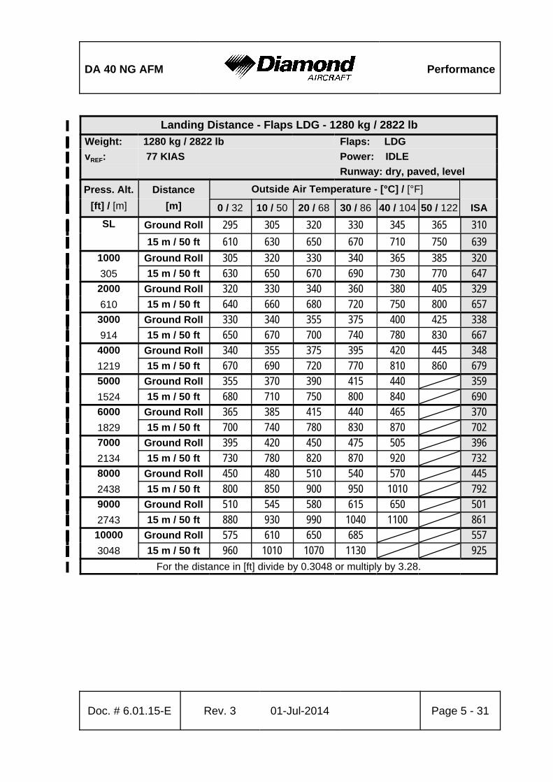
DA 40 NG AFM Performance
Doc. # 6.01.15-E Rev. 3 01-Jul-2014 Page 5 - 31
Landing Distance - Flaps LDG - 1280 kg / 2822 lb%
Weight:% 1280 kg / 2822 lb%% Flaps: LDG%
vREF:% 77 KIAS%% Power: IDLE%
%%% Runway: dry, paved, level%
Press. Alt.%
[ft] / [m]%
Distance%
[m]%
Outside Air Temperature - [°C] / [°F]%%%%
0 / 32% 10 / 50% 20 / 68% 30 / 86% 40 / 104% 50 / 122% ISA%
SL%
%
Ground Roll% 295% 305% 320% 330% 345% 365% 310%%15 m / 50 ft% 610% 630% 650% 670% 710% 750% 639%
1000%
305%
Ground Roll% 305% 320% 330% 340% 365% 385% 320%%15 m / 50 ft% 630% 650% 670% 690% 730% 770% 647%
2000%
610%
Ground Roll% 320% 330% 340% 360% 380% 405% 329%%15 m / 50 ft% 640% 660% 680% 720% 750% 800% 657%
3000%
914%
Ground Roll% 330% 340% 355% 375% 400% 425% 338%%15 m / 50 ft% 650% 670% 700% 740% 780% 830% 667%
4000%
1219%
Ground Roll% 340% 355% 375% 395% 420% 445% 348%%15 m / 50 ft% 670% 690% 720% 770% 810% 860% 679%
5000%
1524%
Ground Roll% 355% 370% 390% 415% 440%% 359%%15 m / 50 ft% 680% 710% 750% 800% 840%% 690%
6000%
1829%
Ground Roll% 365% 385% 415% 440% 465%% 370%%15 m / 50 ft% 700% 740% 780% 830% 870%% 702%
7000%
2134%
Ground Roll% 395% 420% 450% 475% 505%% 396%%15 m / 50 ft% 730% 780% 820% 870% 920%% 732%
8000%
2438%
Ground Roll% 450% 480% 510% 540% 570%% 445%%15 m / 50 ft% 800% 850% 900% 950% 1010%% 792%
9000%
2743%
Ground Roll% 510% 545% 580% 615% 650%% 501%%15 m / 50 ft% 880% 930% 990% 1040% 1100%% 861%
10000%
3048%
Ground Roll% 575% 610% 650% 685%%% 557%%15 m / 50 ft% 960% 1010% 1070% 1130%%% 925%
For the distance in [ft] divide by 0.3048 or multiply by 3.28.%
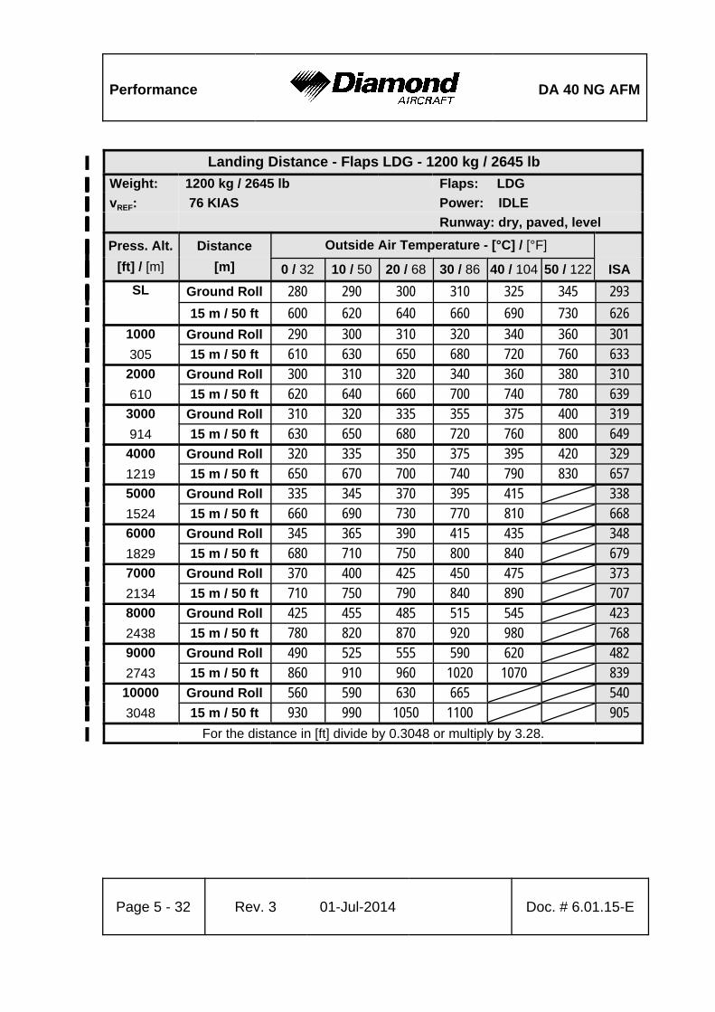
Performance DA 40 NG AFM
Page 5 - 32 Rev. 3 01-Jul-2014 Doc. # 6.01.15-E
Landing Distance - Flaps LDG - 1200 kg / 2645 lb%
Weight:% 1200 kg / 2645 lb%% Flaps: LDG%
vREF:% 76 KIAS%% Power: IDLE%
%%% Runway: dry, paved, level%
Press. Alt.%
[ft] / [m]%
Distance%
[m]%
Outside Air Temperature - [°C] / [°F]%%%%
0 / 32% 10 / 50% 20 / 68% 30 / 86% 40 / 104% 50 / 122% ISA%
SL%
%
Ground Roll% 280% 290% 300% 310% 325% 345% 293%%15 m / 50 ft% 600% 620% 640% 660% 690% 730% 626%
1000%
305%
Ground Roll% 290% 300% 310% 320% 340% 360% 301%%15 m / 50 ft% 610% 630% 650% 680% 720% 760% 633%
2000%
610%
Ground Roll% 300% 310% 320% 340% 360% 380% 310%%15 m / 50 ft% 620% 640% 660% 700% 740% 780% 639%
3000%
914%
Ground Roll% 310% 320% 335% 355% 375% 400% 319%%15 m / 50 ft% 630% 650% 680% 720% 760% 800% 649%
4000%
1219%
Ground Roll% 320% 335% 350% 375% 395% 420% 329%%15 m / 50 ft% 650% 670% 700% 740% 790% 830% 657%
5000%
1524%
Ground Roll% 335% 345% 370% 395% 415%% 338%%15 m / 50 ft% 660% 690% 730% 770% 810%% 668%
6000%
1829%
Ground Roll% 345% 365% 390% 415% 435%% 348%%15 m / 50 ft% 680% 710% 750% 800% 840%% 679%
7000%
2134%
Ground Roll% 370% 400% 425% 450% 475%% 373%%15 m / 50 ft% 710% 750% 790% 840% 890%% 707%
8000%
2438%
Ground Roll% 425% 455% 485% 515% 545%% 423%%15 m / 50 ft% 780% 820% 870% 920% 980%% 768%
9000%
2743%
Ground Roll% 490% 525% 555% 590% 620%% 482%%15 m / 50 ft% 860% 910% 960% 1020% 1070%% 839%
10000%
3048%
Ground Roll% 560% 590% 630% 665%%% 540%%15 m / 50 ft% 930% 990% 1050% 1100%%% 905%
For the distance in [ft] divide by 0.3048 or multiply by 3.28.%

DA 40 NG AFM Performance
Doc. # 6.01.15-E Rev. 3 01-Jul-2014 Page 5 - 33
Landing Distance - Flaps LDG - 1100 kg / 2425 lb%
Weight:% 1100 kg / 2425 lb%% Flaps: LDG%
vREF:% 72 KIAS%% Power: IDLE%
%%% Runway: dry, paved, level%
Press. Alt.%
[ft] / [m]%
Distance%
[m]%
Outside Air Temperature - [°C] / [°F]%%%%
0 / 32% 10 / 50% 20 / 68% 30 / 86% 40 / 104% 50 / 122% ISA%
SL%
%
Ground Roll% 255% 265% 275% 285% 300% 320% 270%%15 m / 50 ft% 590% 610% 630% 640% 680% 720% 612%
1000%
305%
Ground Roll% 265% 275% 285% 295% 315% 335% 278%%15 m / 50 ft% 590% 610% 630% 660% 690% 730% 615%
2000%
610%
Ground Roll% 275% 285% 295% 310% 330% 350% 286%%15 m / 50 ft% 600% 620% 640% 670% 710% 750% 617%
3000%
914%
Ground Roll% 285% 295% 310% 330% 345% 370% 294%%15 m / 50 ft% 610% 630% 650% 690% 730% 770% 623%
4000%
1219%
Ground Roll% 295% 305% 325% 345% 365% 385% 302%%15 m / 50 ft% 620% 640% 670% 710% 750% 800% 630%
5000%
1524%
Ground Roll% 305% 320% 340% 360% 385%% 311%%15 m / 50 ft% 630% 650% 690% 730% 780%% 637%
6000%
1829%
Ground Roll% 320% 335% 355% 380% 405%% 321%%15 m / 50 ft% 640% 680% 720% 760% 800%% 644%
7000%
2134%
Ground Roll% 345% 365% 390% 415% 440%% 345%%15 m / 50 ft% 670% 710% 750% 800% 840%% 671%
8000%
2438%
Ground Roll% 400% 425% 450% 480% 510%% 394%%15 m / 50 ft% 740% 790% 840% 880% 930%% 736%
9000%
2743%
Ground Roll% 465% 495% 525% 560% 590%% 457%%15 m / 50 ft% 830% 880% 930% 980% 1030%% 810%
10000%
3048%
Ground Roll% 535% 565% 600% 635%%% 518%%15 m / 50 ft% 910% 960% 1010% 1070%%% 880%
For the distance in [ft] divide by 0.3048 or multiply by 3.28.%
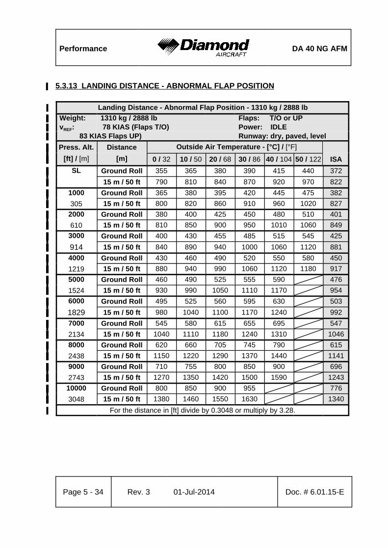
Performance DA 40 NG AFM
Page 5 - 34 Rev. 3 01-Jul-2014 Doc. # 6.01.15-E
5.3.13 LANDING DISTANCE - ABNORMAL FLAP POSITION%
Landing Distance - Abnormal Flap Position - 1310 kg / 2888 lb%
Weight:% 1310 kg / 2888 lb%% Flaps: T/O or UP%vREF:% 78 KIAS (Flaps T/O)%% Power: IDLE% 83 KIAS Flaps UP)%%% Runway: dry, paved, level%
Press. Alt.%
[ft] / [m]%
Distance%
[m]%
Outside Air Temperature - [°C] / [°F]%%%%
0 / 32% 10 / 50% 20 / 68% 30 / 86% 40 / 104% 50 / 122% ISA%
SL%
%
Ground Roll% 355% 365% 380% 390% 415% 440% 372%%15 m / 50 ft% 790% 810% 840% 870% 920% 970% 822%
1000%
305%
Ground Roll% 365% 380% 395% 420% 445% 475% 382%%15 m / 50 ft% 800% 820% 860% 910% 960% 1020% 827%
2000%
610%
Ground Roll% 380% 400% 425% 450% 480% 510% 401%%15 m / 50 ft% 810% 850% 900% 950% 1010% 1060% 849%
3000%
914%
Ground Roll% 400% 430% 455% 485% 515% 545% 425%%15 m / 50 ft% 840% 890% 940% 1000% 1060% 1120% 881%
4000%
1219%
Ground Roll% 430% 460% 490% 520% 550% 580% 450%%15 m / 50 ft% 880% 940% 990% 1060% 1120% 1180% 917%
5000%
1524%
Ground Roll% 460% 490% 525% 555% 590%% 476%%15 m / 50 ft% 930% 990% 1050% 1110% 1170%% 954%
6000%
1829%
Ground Roll% 495% 525% 560% 595% 630%% 503%%15 m / 50 ft% 980% 1040% 1100% 1170% 1240%% 992%
7000%
2134%
Ground Roll% 545% 580% 615% 655% 695%% 547%%15 m / 50 ft% 1040% 1110% 1180% 1240% 1310%% 1046%
8000%
2438%
Ground Roll% 620% 660% 705% 745% 790%% 615%%15 m / 50 ft% 1150% 1220% 1290% 1370% 1440%% 1141%
9000%
2743%
Ground Roll% 710% 755% 800% 850% 900%% 696%%15 m / 50 ft% 1270% 1350% 1420% 1500% 1590%% 1243%
10000%
3048%
Ground Roll% 800% 850% 900% 955%%% 776%%15 m / 50 ft% 1380% 1460% 1550% 1630%%% 1340%
For the distance in [ft] divide by 0.3048 or multiply by 3.28.%
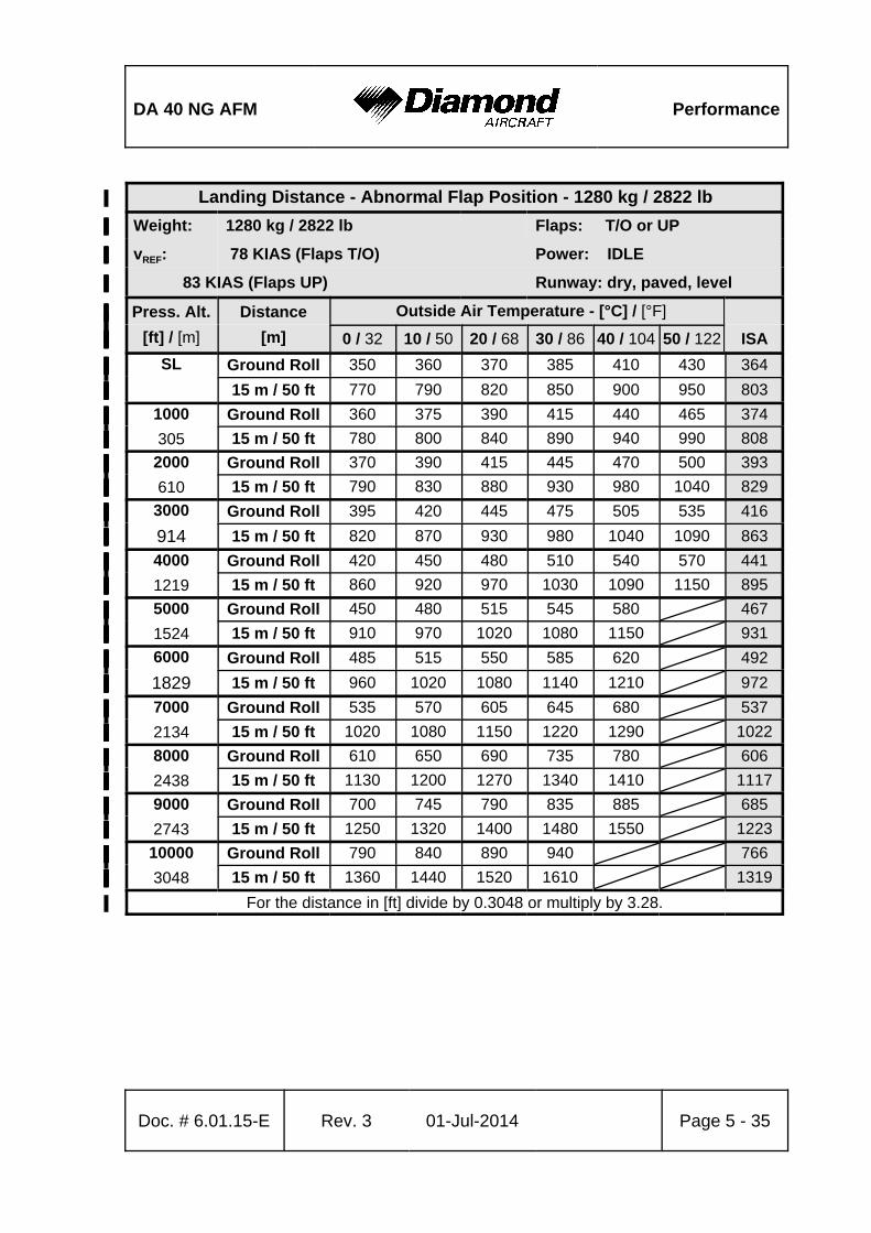
DA 40 NG AFM Performance
Doc. # 6.01.15-E Rev. 3 01-Jul-2014 Page 5 - 35
Landing Distance - Abnormal Flap Position - 1280 kg / 2822 lb%
Weight:% 1280 kg / 2822 lb%% Flaps: T/O or UP%
vREF:% 78 KIAS (Flaps T/O)%% Power: IDLE%
83 KIAS (Flaps UP)%%% Runway: dry, paved, level%
Press. Alt.%
[ft] / [m]%
Distance%
[m]%
Outside Air Temperature - [°C] / [°F]%%%%
0 / 32% 10 / 50% 20 / 68% 30 / 86% 40 / 104% 50 / 122% ISA%
SL%
%
Ground Roll% 350% 360% 370% 385% 410% 430% 364%%15 m / 50 ft% 770% 790% 820% 850% 900% 950% 803%
1000%
305%
Ground Roll% 360% 375% 390% 415% 440% 465% 374%%15 m / 50 ft% 780% 800% 840% 890% 940% 990% 808%
2000%
610%
Ground Roll% 370% 390% 415% 445% 470% 500% 393%%15 m / 50 ft% 790% 830% 880% 930% 980% 1040% 829%
3000%
914%
Ground Roll% 395% 420% 445% 475% 505% 535% 416%%15 m / 50 ft% 820% 870% 930% 980% 1040% 1090% 863%
4000%
1219%
Ground Roll% 420% 450% 480% 510% 540% 570% 441%%15 m / 50 ft% 860% 920% 970% 1030% 1090% 1150% 895%
5000%
1524%
Ground Roll% 450% 480% 515% 545% 580%% 467%%15 m / 50 ft% 910% 970% 1020% 1080% 1150%% 931%
6000%
1829%
Ground Roll% 485% 515% 550% 585% 620%% 492%%15 m / 50 ft% 960% 1020% 1080% 1140% 1210%% 972%
7000%
2134%
Ground Roll% 535% 570% 605% 645% 680%% 537%%15 m / 50 ft% 1020% 1080% 1150% 1220% 1290%% 1022%
8000%
2438%
Ground Roll% 610% 650% 690% 735% 780%% 606%%15 m / 50 ft% 1130% 1200% 1270% 1340% 1410%% 1117%
9000%
2743%
Ground Roll% 700% 745% 790% 835% 885%% 685%%15 m / 50 ft% 1250% 1320% 1400% 1480% 1550%% 1223%
10000%
3048%
Ground Roll% 790% 840% 890% 940%%% 766%%15 m / 50 ft% 1360% 1440% 1520% 1610%%% 1319%
For the distance in [ft] divide by 0.3048 or multiply by 3.28.%
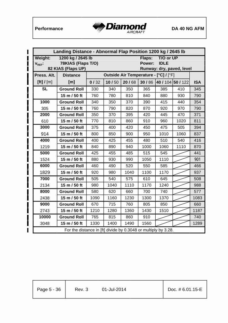
Performance DA 40 NG AFM
Page 5 - 36 Rev. 3 01-Jul-2014 Doc. # 6.01.15-E
Landing Distance - Abnormal Flap Position 1200 kg / 2645 lb%
Weight:% 1200 kg / 2645 lb%% Flaps: T/O or UP%vREF:% 78KIAS (Flaps T/O)%% Power: IDLE% 82 KIAS (Flaps UP)%%% Runway: dry, paved, level%
Press. Alt.%
[ft] / [m]%
Distance%
[m]%
Outside Air Temperature - [°C] / [°F]%%%%
0 / 32% 10 / 50% 20 / 68% 30 / 86% 40 / 104% 50 / 122% ISA%
SL%
%
Ground Roll% 330% 340% 350% 365% 385% 410% 345%%15 m / 50 ft% 760% 780% 810% 840% 880% 930% 790%
1000%
305%
Ground Roll% 340% 350% 370% 390% 415% 440% 354%%15 m / 50 ft% 760% 790% 820% 870% 920% 970% 790%
2000%
610%
Ground Roll% 350% 370% 395% 420% 445% 470% 371%%15 m / 50 ft% 770% 810% 860% 910% 960% 1020% 811%
3000%
914%
Ground Roll% 375% 400% 420% 450% 475% 505% 394%%15 m / 50 ft% 800% 850% 900% 950% 1010% 1060% 837%
4000%
1219%
Ground Roll% 400% 425% 455% 480% 510% 540% 416%%15 m / 50 ft% 840% 890% 940% 1000% 1060% 1110% 870%
5000%
1524%
Ground Roll% 425% 455% 485% 515% 545%% 441%%15 m / 50 ft% 880% 930% 990% 1050% 1110%% 901%
6000%
1829%
Ground Roll% 460% 490% 520% 550% 585%% 466%%15 m / 50 ft% 920% 980% 1040% 1100% 1170%% 937%
7000%
2134%
Ground Roll% 505% 540% 575% 610% 645%% 508%%15 m / 50 ft% 980% 1040% 1110% 1170% 1240%% 988%
8000%
2438%
Ground Roll% 580% 620% 660% 700% 740%% 577%%15 m / 50 ft% 1090% 1160% 1230% 1300% 1370%% 1083%
9000%
2743%
Ground Roll% 670% 715% 760% 805% 850%% 660%%15 m / 50 ft% 1210% 1280% 1360% 1430% 1510%% 1187%
10000%
3048%
Ground Roll% 765% 815% 860% 910%%% 740%%15 m / 50 ft% 1330% 1400% 1490% 1560%%% 1289%
For the distance in [ft] divide by 0.3048 or multiply by 3.28.%

DA 40 NG AFM Performance
Doc. # 6.01.15-E Rev. 3 01-Jul-2014 Page 5 - 37
Landing Distance - Abnormal Flap Position 1100 kg / 2425 lb%
Weight:% 1100 kg / 2425 lb%% Flaps: T/O or UP%vREF:% 74 KIAS (Flaps T/O)%% Power: IDLE% 78 KIAS (Flaps UP)%%% Runway: dry, paved, level%
Press. Alt.%
[ft] / [m]%
Distance%
[m]%
Outside Air Temperature - [°C] / [°F]%%%%
0 / 32% 10 / 50% 20 / 68% 30 / 86% 40 / 104% 50 / 122% ISA%
SL%
%
Ground Roll% 305% 315% 325% 335% 355% 380% 319%%15 m / 50 ft% 750% 770% 790% 820% 870% 920% 777%
1000%
305%
Ground Roll% 315% 325% 340% 360% 385% 405% 328%%15 m / 50 ft% 750% 770% 800% 850% 900% 950% 780%
2000%
610%
Ground Roll% 325% 345% 365% 390% 410% 435% 343%%15 m / 50 ft% 760% 780% 830% 880% 930% 980% 783%
3000%
914%
Ground Roll% 345% 370% 390% 415% 440% 465% 364%%15 m / 50 ft% 760% 810% 860% 920% 970% 1020% 804%
4000%
1219%
Ground Roll% 370% 395% 420% 445% 470% 500% 386%%15 m / 50 ft% 800% 850% 900% 950% 1010% 1060% 829%
5000%
1524%
Ground Roll% 395% 420% 450% 475% 505%% 408%%15 m / 50 ft% 840% 890% 940% 1000% 1050%% 857%
6000%
1829%
Ground Roll% 425% 450% 480% 510% 540%% 431%%15 m / 50 ft% 870% 930% 990% 1040% 1100%% 887%
7000%
2134%
Ground Roll% 470% 500% 535% 565% 600%% 471%%15 m / 50 ft% 930% 990% 1050% 1110% 1170%% 936%
8000%
2438%
Ground Roll% 545% 580% 620% 655% 695%% 542%%15 m / 50 ft% 1040% 1100% 1170% 1240% 1300%% 1031%
9000%
2743%
Ground Roll% 640% 680% 720% 765% 805%% 627%%15 m / 50 ft% 1170% 1230% 1310% 1380% 1450%% 1141%
10000%
3048%
Ground Roll% 735% 780% 825% 870%%% 712%%15 m / 50 ft% 1280% 1360% 1430% 1510%%% 1242%
For the distance in [ft] divide by 0.3048 or multiply by 3.28.%
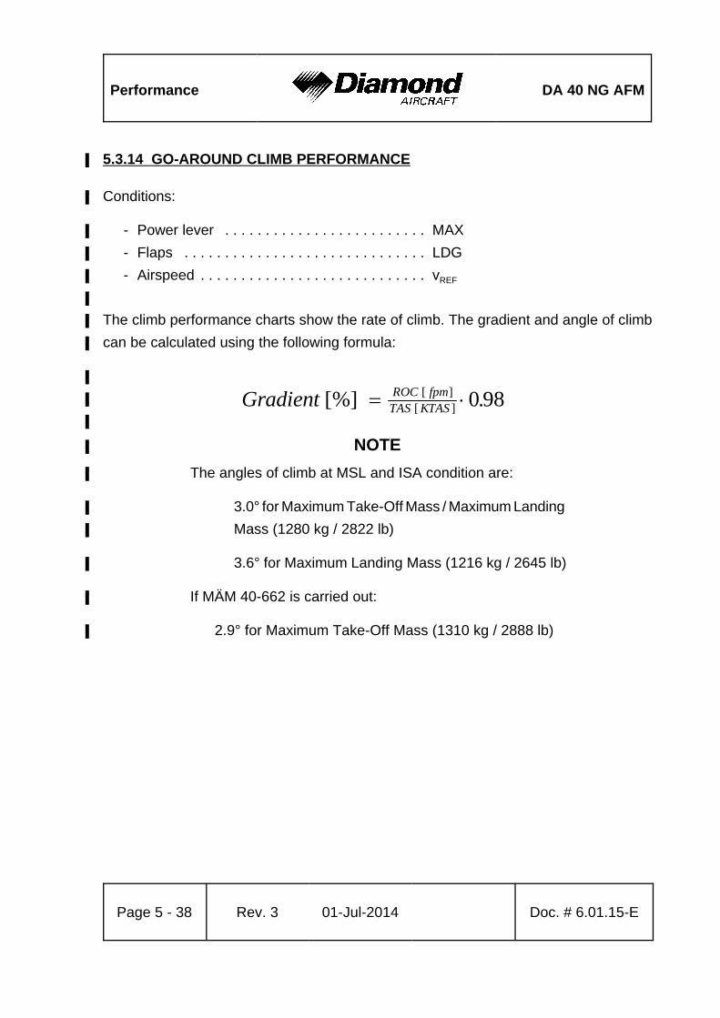
Performance DA 40 NG AFM
Page 5 - 38 Rev. 3 01-Jul-2014 Doc. # 6.01.15-E
Gradient ROC fpmTAS KTAS
[%] .[ ][ ] 0 98
5.3.14 GO-AROUND CLIMB PERFORMANCE%
Conditions:%
- Power lever . . . . . . . . . . . . . . . . . . . . . . . . . MAX%
- Flaps . . . . . . . . . . . . . . . . . . . . . . . . . . . . . . LDG%
- Airspeed . . . . . . . . . . . . . . . . . . . . . . . . . . . . vREF%
%
The climb performance charts show the rate of climb. The gradient and angle of climb%
can be calculated using the following formula: %
%
%
%
NOTE%
The angles of climb at MSL and ISA condition are:%
3.0° for Maximum Take-Off Mass / Maximum Landing%
Mass (1280 kg / 2822 lb)%
3.6° for Maximum Landing Mass (1216 kg / 2645 lb)%
If MÄM 40-662 is carried out:%
2.9° for Maximum Take-Off Mass (1310 kg / 2888 lb)%
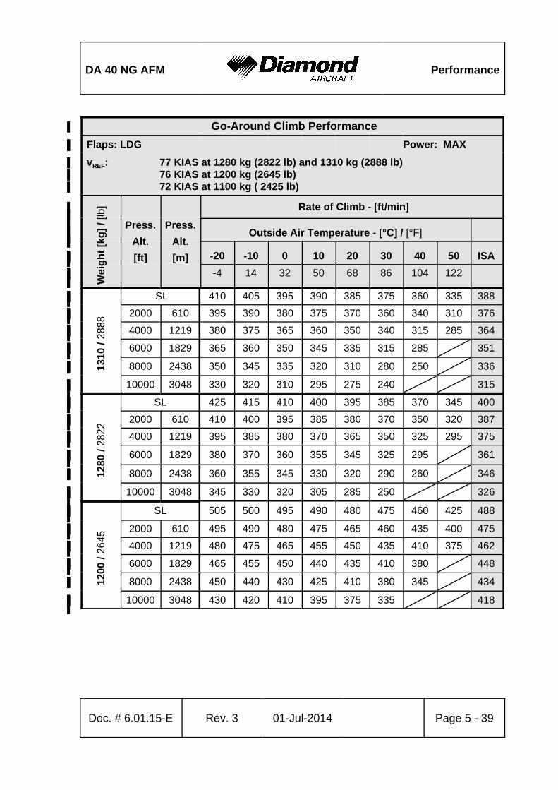
DA 40 NG AFM Performance
Doc. # 6.01.15-E Rev. 3 01-Jul-2014 Page 5 - 39
Go-Around Climb Performance%
Flaps: LDG%%%%%%% Power: MAX%
vREF: 77 KIAS at 1280 kg (2822 lb) and 1310 kg (2888 lb)%76 KIAS at 1200 kg (2645 lb)%72 KIAS at 1100 kg ( 2425 lb)%
% Wei
gh
t [k
g]
/ [lb
]
Press.%
Alt.%
[ft]%
Press.%
Alt.%
[m]%
Rate of Climb - [ft/min]%%%%
Outside Air Temperature - [°C] / [°F]%%%%%
-20% -10% 0% 10% 20% 30% 40% 50% ISA%%
%%-4% 14% 32% 50% 68% 86% 104% 122%%
% 1310
/ 28
88
SL% 410% 405% 395% 390% 385% 375% 360% 335% 388%%2000% 610% 395% 390% 380% 375% 370% 360% 340% 310% 376%%4000% 1219% 380% 375% 365% 360% 350% 340% 315% 285% 364%%6000% 1829% 365% 360% 350% 345% 335% 315% 285%% 351%%8000% 2438% 350% 345% 335% 320% 310% 280% 250%% 336%
%10000% 3048% 330% 320% 310% 295% 275% 240%%% 315%
% 1280
/ 28
22
SL% 425% 415% 410% 400% 395% 385% 370% 345% 400%%2000% 610% 410% 400% 395% 385% 380% 370% 350% 320% 387%%4000% 1219% 395% 385% 380% 370% 365% 350% 325% 295% 375%%6000% 1829% 380% 370% 360% 355% 345% 325% 295%% 361%
%8000% 2438% 360% 355% 345% 330% 320% 290% 260%% 346%
%10000% 3048% 345% 330% 320% 305% 285% 250%%% 326%
% 1200
/ 26
45
SL% 505% 500% 495% 490% 480% 475% 460% 425% 488%%
2000% 610% 495% 490% 480% 475% 465% 460% 435% 400% 475%%4000% 1219% 480% 475% 465% 455% 450% 435% 410% 375% 462%%6000% 1829% 465% 455% 450% 440% 435% 410% 380%% 448%%8000% 2438% 450% 440% 430% 425% 410% 380% 345%% 434%
%10000% 3048% 430% 420% 410% 395% 375% 335%%% 418%
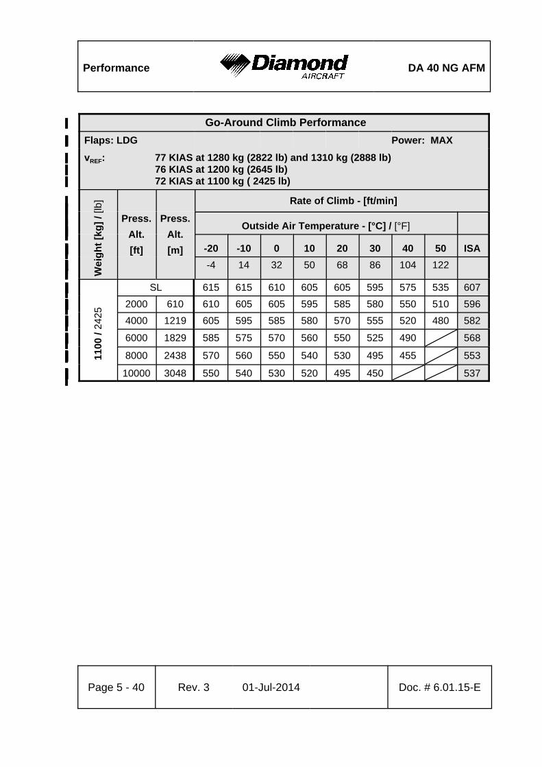
Performance DA 40 NG AFM
Go-Around Climb Performance%
Flaps: LDG%%%%%%% Power: MAX%
vREF: 77 KIAS at 1280 kg (2822 lb) and 1310 kg (2888 lb)%76 KIAS at 1200 kg (2645 lb)%72 KIAS at 1100 kg ( 2425 lb)%
% Wei
gh
t [k
g]
/ [lb
]
Press.%
Alt.%
[ft]%
Press.%
Alt.%
[m]%
Rate of Climb - [ft/min]%%%%
Outside Air Temperature - [°C] / [°F]%%%%%
-20% -10% 0% 10% 20% 30% 40% 50% ISA%%
%%-4% 14% 32% 50% 68% 86% 104% 122%%
Page 5 - 40 Rev. 3 01-Jul-2014 Doc. # 6.01.15-E
% 1100
/ 24
25
SL% 615% 615% 610% 605% 605% 595% 575% 535% 607%%2000% 610% 610% 605% 605% 595% 585% 580% 550% 510% 596%%4000% 1219% 605% 595% 585% 580% 570% 555% 520% 480% 582%%6000% 1829% 585% 575% 570% 560% 550% 525% 490%% 568%%8000% 2438% 570% 560% 550% 540% 530% 495% 455%% 553%
%10000% 3048% 550% 540% 530% 520% 495% 450%%% 537%
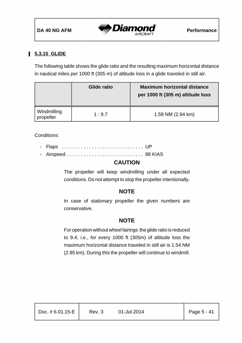
DA 40 NG AFM Performance
Doc. # 6.01.15-E Rev. 3 01-Jul-2014 Page 5 - 41
5.3.15 GLIDE%
The following table shows the glide ratio and the resulting maximum horizontal distance
in nautical miles per 1000 ft (305 m) of altitude loss in a glide traveled in still air.
Glide ratio Maximum horizontal distance
per 1000 ft (305 m) altitude loss
Windmillingpropeller
1 : 9.7 1.59 NM (2.94 km)
Conditions:
- Flaps . . . . . . . . . . . . . . . . . . . . . . . . . . . . . . UP
- Airspeed . . . . . . . . . . . . . . . . . . . . . . . . . . . . 88 KIAS
CAUTION
The propeller will keep windmilling under all expected
conditions. Do not attempt to stop the propeller intentionally.
NOTE
In case of stationary propeller the given numbers are
conservative.
NOTE
For operation without wheel fairings the glide ratio is reduced
to 9.4; i.e., for every 1000 ft (305m) of altitude loss the
maximum horizontal distance traveled in still air is 1.54 NM
(2.85 km). During this the propeller will continue to windmill.
Performance DA 40 NG AFM
Page 5 - 42 Rev. 3 01-Jul-2014 Doc. # 6.01.15-E
5.3.16 APPROVED NOISE DATA%
Maximum Flight Mass 1280 kg (2825 lb):%
ICAO Annex 16 Chapter X . . . . . . . . . . . . . . . . . . 74.5 dB(A)
CS-36 Subpart C . . . . . . . . . . . . . . . . . . . . . . . . . 74.5 dB(A)
If the Exhaust Pipe with Muffler MÄM 40-434 or OÄM 40-310 is installed:%
ICAO Annex 16, Chapter X . . . . . . . . . . . . . . . . . . 71.5 dB(A)%
CS-36 Subpart C . . . . . . . . . . . . . . . . . . . . . . . . . 71.5 dB(A)%
Maximum Flight Mass 1310 kg (2888 lb):%
ICAO Annex 16 Chapter X . . . . . . . . . . . . . . . . . . 71.4 dB(A) %
CS-36 Subpart C . . . . . . . . . . . . . . . . . . . . . . . . . 71.4 dB(A) %
DA 40 NG AFM Mass & Balance
Doc. # 6.01.15-E Rev. 3 01-Jul-2014 Page 6 - 1
CHAPTER 6
MASS AND BALANCE / EQUIPMENT LIST
Page
6.1 INTRODUCTION . . . . . . . . . . . . . . . . . . . . . . . . . . . . . . . . . . . . . . . 6-2
6.2 DATUM PLANE . . . . . . . . . . . . . . . . . . . . . . . . . . . . . . . . . . . . . . . . 6-3
6.3 MASS AND BALANCE REPORT . . . . . . . . . . . . . . . . . . . . . . . . . . 6-3
6.4 FLIGHT MASS AND CENTER OF GRAVITY . . . . . . . . . . . . . . . . . 6-5
6.4.1 MOMENT ARMS . . . . . . . . . . . . . . . . . . . . . . . . . . . . . . . . . . 6-7
6.4.2 LOADING DIAGRAM . . . . . . . . . . . . . . . . . . . . . . . . . . . . . . 6-8
6.4.3 CALCULATION OF LOADING CONDITION . . . . . . . . . . . . . 6-9
6.4.4 PERMISSIBLE CENTER OF GRAVITY RANGE . . . . . . . . 6-13
6.4.5 PERMISSIBLE MOMENT RANGE . . . . . . . . . . . . . . . . . . . 6-14
6.5 EQUIPMENT LIST AND EQUIPMENT INVENTORY . . . . . . . . . . 6-15
Mass & Balance DA 40 NG AFM
Page 6 - 2 Rev. 3 01-Jul-2014 Doc. # 6.01.15-E
6.1 INTRODUCTION
In order to achieve the performance and flight characteristics described in this Airplane
Flight Manual and for safe flight operation, the airplane must be operated within the
permissible mass and balance envelope.
The pilot is responsible for adhering to the permissible values for loading and center of
gravity (CG). In this, he should note the movement of the CG due to fuel consumption.
The permissible CG range during flight is given in Chapter 2.
The procedure for determining the flight mass CG position is described in this Chapter.
Over and above this there is a comprehensive list of the equipment approved for this
airplane (Equipment List), as also a list of that equipment installed when the airplane was
weighed (Equipment Inventory).
Before the airplane is delivered the empty mass and the corresponding CG position are
determined, and entered in Section 6.3 - MASS AND BALANCE REPORT.
NOTE
Following equipment changes the new empty mass and the
corresponding CG position must be determined by calculation
or by weighing.
Following repairs or repainting the new empty mass and the
corresponding CG position must be determined by weighing.
Empty mass, empty mass CG position, and the empty mass
moment must be certified in the Mass and Balance Report
by an authorized person.
DA 40 NG AFM Mass & Balance
Doc. # 6.01.15-E Rev. 3 01-Jul-2014 Page 6 - 3
NOTE
Refer to Section 1.6 - UNITS OF MEASUREMENT for
conversion of SI units to US units and vice versa.
6.2 DATUM PLANE
The Datum Plane (DP) is a plane which is normal to the airplane’s longitudinal axis and
in front of the airplane as seen from the direction of flight. The airplane’s longitudinal axis
is parallel with the upper surface of a 600:31 wedge which is placed on top of the rear
fuselage in front of the vertical stabilizer. When the upper surface of the wedge is aligned
horizontally, the Datum Plane is vertical. The Datum Plane is located 2.194 meter
(86.38 in) forward of the most forward point of the root rib on the stub wing.
6.3 MASS AND BALANCE REPORT
The empty mass and the corresponding CG position established before delivery are the
first entries in the Mass and Balance Report. Every change in permanently installed
equipment, and every repair to the airplane which affects the empty mass or the empty
mass CG must be recorded in the Mass and Balance Report.
For the calculation of flight mass and corresponding CG position (or moment), the current
empty mass and the corresponding CG position (or moment) in accordance with the Mass
and Balance Report must always be used.
Condition of the airplane for establishing the empty mass:
- Equipment as per Equipment Inventory (see Section 6.5)
- Including brake fluid, lubricant (1.0 liter / 1.06 qts), coolant, gearbox oil, engine oil (7.0%
liter / 7.4 qts), plus unusable fuel (2.0 US gal / approx. 7.6 liter).%
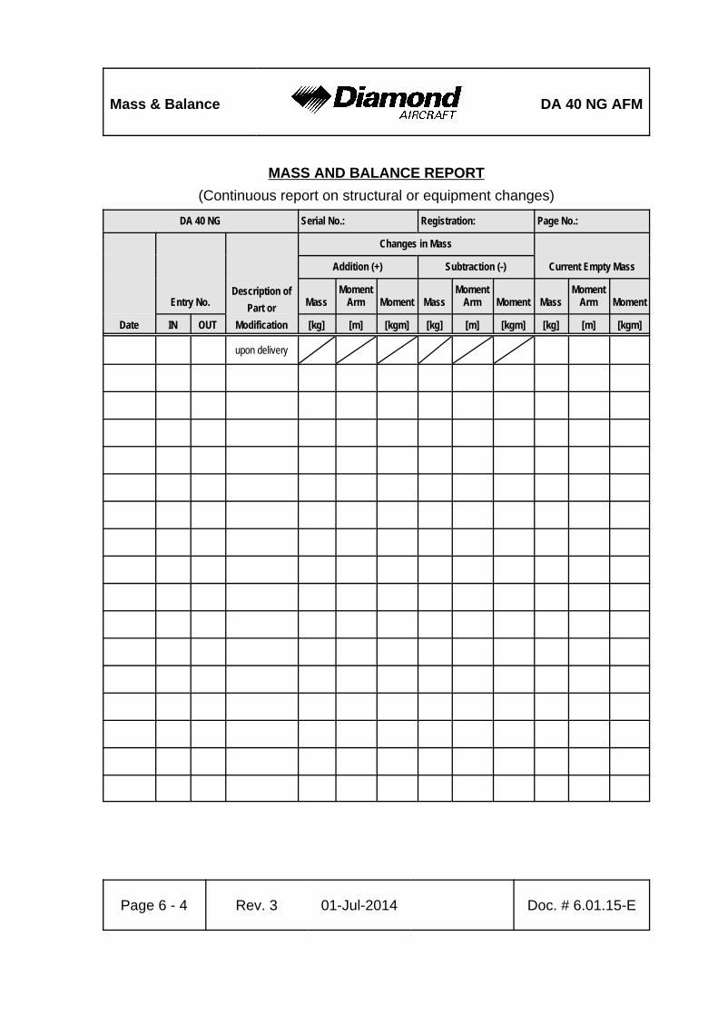
Mass & Balance DA 40 NG AFM
Page 6 - 4 Rev. 3 01-Jul-2014 Doc. # 6.01.15-E
MASS AND BALANCE REPORT
(Continuous report on structural or equipment changes)
DA 40 NG Serial No.: Registration: Page No.:
Date
Entry No.Description of
Part or
Modification
Changes in Mass
Current Empty MassAddition (+) Subtraction (-)
MassMoment
Arm Moment MassMoment
Arm Moment MassMoment
Arm Moment
IN OUT [kg] [m] [kgm] [kg] [m] [kgm] [kg] [m] [kgm]
upon delivery
DA 40 NG AFM Mass & Balance
Doc. # 6.01.15-E Rev. 3 01-Jul-2014 Page 6 - 5
6.4 FLIGHT MASS AND CENTER OF GRAVITY
The following information enables you to operate your DA 40 NG within the permissible
mass and balance limits. For the calculation of the flight mass and the corresponding CG
position the following tables and diagrams are required:
6.4.1 - MOMENT ARMS
6.4.2 - LOADING DIAGRAM
6.4.3 - CALCULATION OF LOADING CONDITION
6.4.4 - PERMISSIBLE CENTER OF GRAVITY RANGE
6.4.5 - PERMISSIBLE MOMENT RANGE
The diagrams should be used as follows:
1. Take the empty mass and the empty mass moment of your airplane from the Mass
and Balance Report, and enter the figures in the appropriate boxes under the column
marked ‘Your DA 40 NG' in Table 6.4.3 - CALCULATION OF LOADING CONDITION.
2. Read the fuel quantity indicators to determine the fuel quantity. If an indicator shows
14 US gal, up to 19.5 US gal can be in the Long Range Tank. In this case, the exact
quantity must be determined with the alternate means for fuel quantity indication.
3. Multiply the individual masses by the moment arms quoted to obtain the moment for
every item of loading and enter these moments in the appropriate boxes in Table
6.4.3 - CALCULATION OF LOADING CONDITION.
4. Add up the masses and moments in the respective columns. The total moments may
be rounded to whole numbers. The CG position is calculated by dividing the total
moment by the total mass (using row 9 for the condition with empty fuel tanks, and%
row 11 for the pre take-off condition). The resulting CG position must be inside the%
limits.
As an illustration the total mass and the CG position are entered on Diagram
6.4.4 - PERMISSIBLE CENTER OF GRAVITY RANGE. This checks graphically that
the current configuration of the airplane is within the permissible range.

Mass & Balance DA 40 NG AFM
Page 6 - 6 Rev. 3 01-Jul-2014 Doc. # 6.01.15-E
5. Graphical method:
Diagram 6.4.2 - LOADING DIAGRAM is used to determine the moments. The masses
and moments for the individual items of loading are added. Then Diagram
6.4.5 - PERMISSIBLE MOMENT RANGE is used to check whether the total moment
associated with the total mass is in the admissible range.
The result found with the graphical method is however inaccurate. In doubtful cases
the result must be verified using the exact method given above.
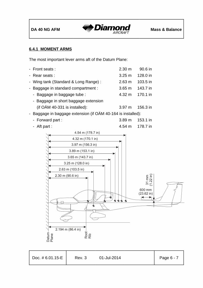
DA 40 NG AFM Mass & Balance
Doc. # 6.01.15-E Rev. 3 01-Jul-2014 Page 6 - 7
6.4.1 MOMENT ARMS
The most important lever arms aft of the Datum Plane:
- Front seats : 2.30 m 90.6 in
- Rear seats : 3.25 m 128.0 in
- Wing tank (Standard & Long Range) : 2.63 m 103.5 in
- Baggage in standard compartment : 3.65 m 143.7 in
- Baggage in baggage tube : 4.32 m 170.1 in
- Baggage in short baggage extension
(if OÄM 40-331 is installed): 3.97 m 156.3 in
- Baggage in baggage extension (if OÄM 40-164 is installed):
- Forward part : 3.89 m 153.1 in
- Aft part : 4.54 m 178.7 in
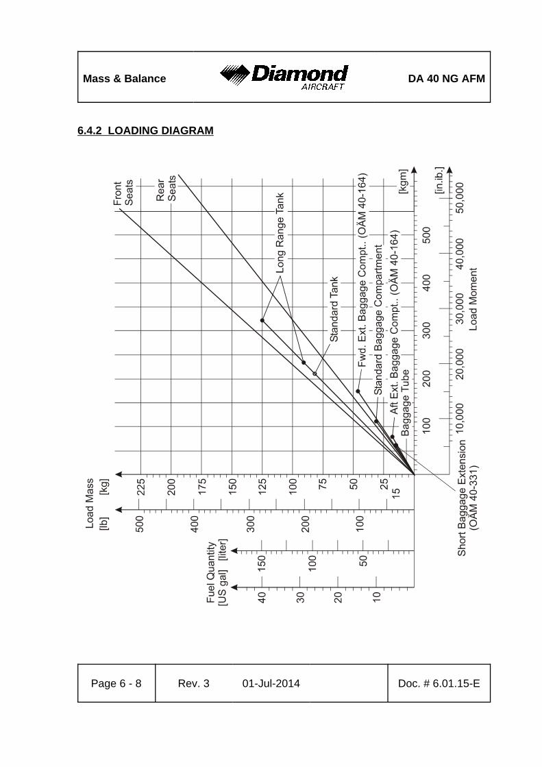
Mass & Balance DA 40 NG AFM
Page 6 - 8 Rev. 3 01-Jul-2014 Doc. # 6.01.15-E
6.4.2 LOADING DIAGRAM
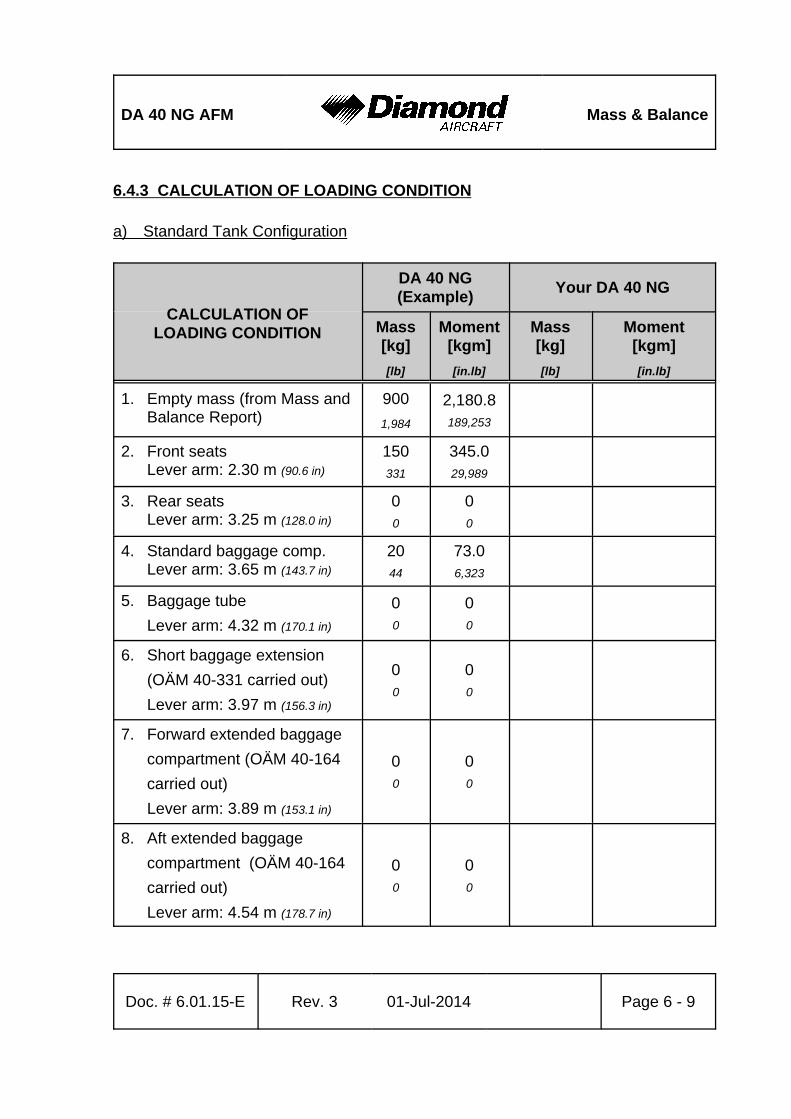
DA 40 NG AFM Mass & Balance
Doc. # 6.01.15-E Rev. 3 01-Jul-2014 Page 6 - 9
6.4.3 CALCULATION OF LOADING CONDITION
a) Standard Tank Configuration
CALCULATION OFLOADING CONDITION
DA 40 NG(Example)
Your DA 40 NG
Mass[kg]
[lb]
Moment[kgm]
[in.lb]
Mass[kg]
[lb]
Moment[kgm]
[in.lb]
1. Empty mass (from Mass andBalance Report)
900
1,984
2,180.8189,253
2. Front seatsLever arm: 2.30 m (90.6 in)
150331
345.029,989
3. Rear seatsLever arm: 3.25 m (128.0 in)
00
00
4. Standard baggage comp.Lever arm: 3.65 m (143.7 in)
2044
73.06,323
5. Baggage tube
Lever arm: 4.32 m (170.1 in)
00
00
6. Short baggage extension
(OÄM 40-331 carried out)
Lever arm: 3.97 m (156.3 in)
00
00
7. Forward extended baggage
compartment (OÄM 40-164
carried out)
Lever arm: 3.89 m (153.1 in)
00
00
8. Aft extended baggage
compartment (OÄM 40-164
carried out)
Lever arm: 4.54 m (178.7 in)
00
00

Mass & Balance DA 40 NG AFM
CALCULATION OFLOADING CONDITION
DA 40 NG(Example)
Your DA 40 NG
Mass[kg]
[lb]
Moment[kgm]
[in.lb]
Mass[kg]
[lb]
Moment[kgm]
[in.lb]
Page 6 - 10 Rev. 3 01-Jul-2014 Doc. # 6.01.15-E
9. Total mass and total momentwith empty fuel tanks (Totalof 1.-8.)
1,0702,359
2,598.8225,565
10. On-board usable fuel(0.84 kg/liter) (7.01 lb/US gal)
Lever arm: 2.63 m (103.5 in)
89196
234.120,286
11. Total mass and total momentwith full fuel tanks (Total 9.plus 10.)
1,1592,555
2,832.9245,851
12. The total moments from rows 9 and 11 2,598.8 and 2,832.9 kgm) (225,565 and
245,851 in.lb) must be divided by the related total mass (1,070 and 1,159 kgrespectively) (2,359 and 2,555 lb) and then located in Diagram 6.4.4 - PERMISSIBLECENTER OF GRAVITY RANGE.
As in our example CG positions (2.429 m and 2.444 m respectively) (95.62 and 96.22 in)
and masses fall into the permitted area, this loading condition is allowable.
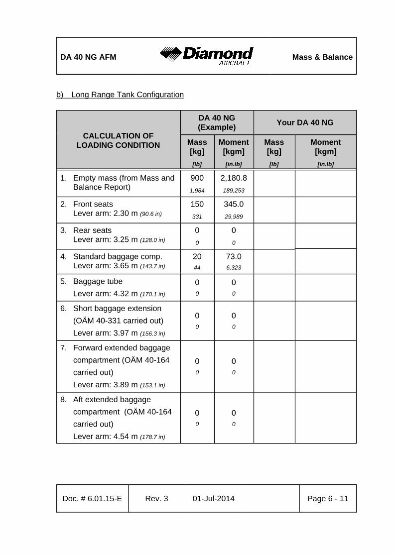
DA 40 NG AFM Mass & Balance
Doc. # 6.01.15-E Rev. 3 01-Jul-2014 Page 6 - 11
b) Long Range Tank Configuration
CALCULATION OFLOADING CONDITION
DA 40 NG(Example)
Your DA 40 NG
Mass[kg]
[lb]
Moment[kgm]
[in.lb]
Mass[kg]
[lb]
Moment[kgm]
[in.lb]
1. Empty mass (from Mass andBalance Report)
900
1,984
2,180.8
189,253
2. Front seatsLever arm: 2.30 m (90.6 in)
150
331
345.0
29,989
3. Rear seatsLever arm: 3.25 m (128.0 in)
0
0
0
0
4. Standard baggage comp.Lever arm: 3.65 m (143.7 in)
2044
73.06,323
5. Baggage tube
Lever arm: 4.32 m (170.1 in)
00
00
6. Short baggage extension
(OÄM 40-331 carried out)
Lever arm: 3.97 m (156.3 in)
00
00
7. Forward extended baggage
compartment (OÄM 40-164
carried out)
Lever arm: 3.89 m (153.1 in)
00
00
8. Aft extended baggage
compartment (OÄM 40-164
carried out)
Lever arm: 4.54 m (178.7 in)
00
00
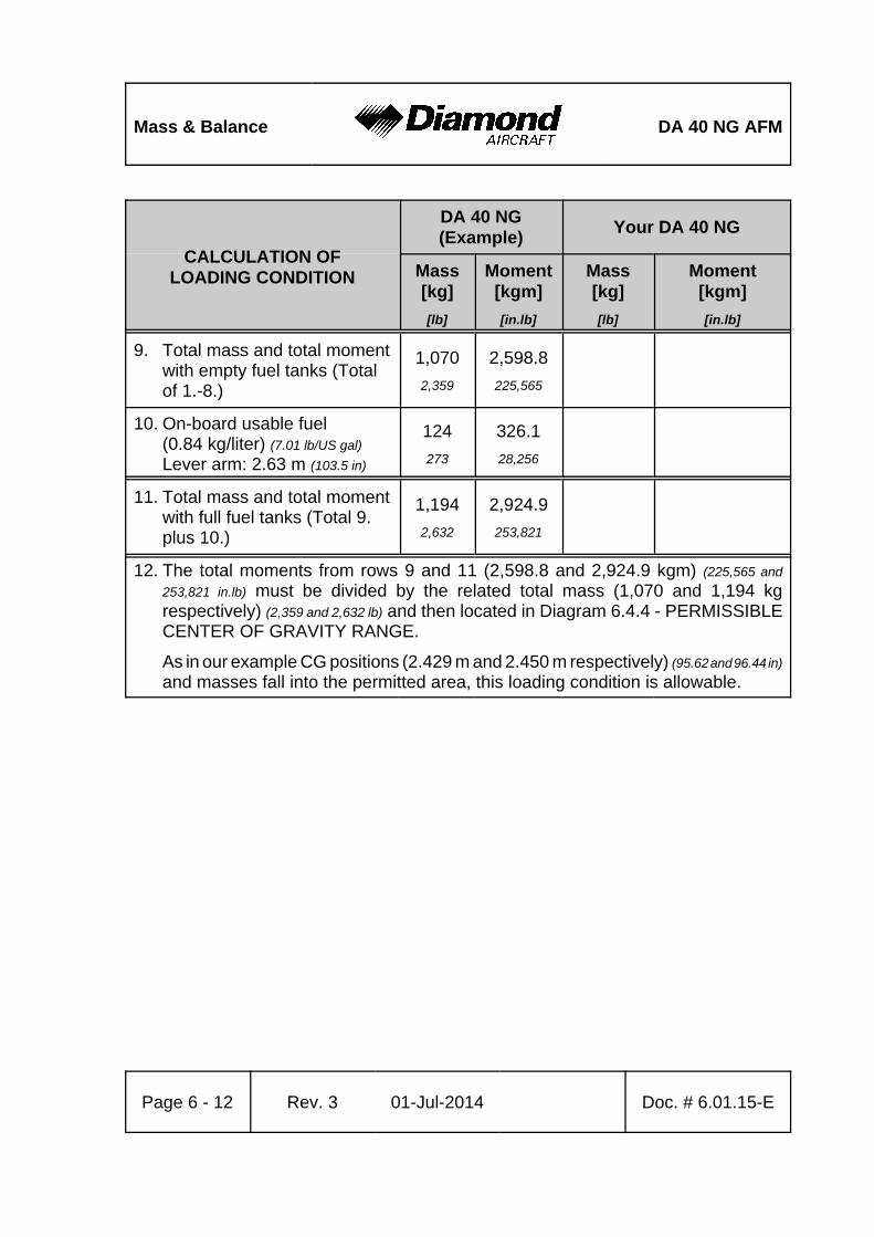
Mass & Balance DA 40 NG AFM
CALCULATION OFLOADING CONDITION
DA 40 NG(Example)
Your DA 40 NG
Mass[kg]
[lb]
Moment[kgm]
[in.lb]
Mass[kg]
[lb]
Moment[kgm]
[in.lb]
Page 6 - 12 Rev. 3 01-Jul-2014 Doc. # 6.01.15-E
9. Total mass and total momentwith empty fuel tanks (Totalof 1.-8.)
1,070
2,359
2,598.8
225,565
10. On-board usable fuel(0.84 kg/liter) (7.01 lb/US gal)
Lever arm: 2.63 m (103.5 in)
124
273
326.1
28,256
11. Total mass and total momentwith full fuel tanks (Total 9.plus 10.)
1,194
2,632
2,924.9
253,821
12. The total moments from rows 9 and 11 (2,598.8 and 2,924.9 kgm) (225,565 and
253,821 in.lb) must be divided by the related total mass (1,070 and 1,194 kgrespectively) (2,359 and 2,632 lb) and then located in Diagram 6.4.4 - PERMISSIBLECENTER OF GRAVITY RANGE.
As in our example CG positions (2.429 m and 2.450 m respectively) (95.62 and 96.44 in)
and masses fall into the permitted area, this loading condition is allowable.
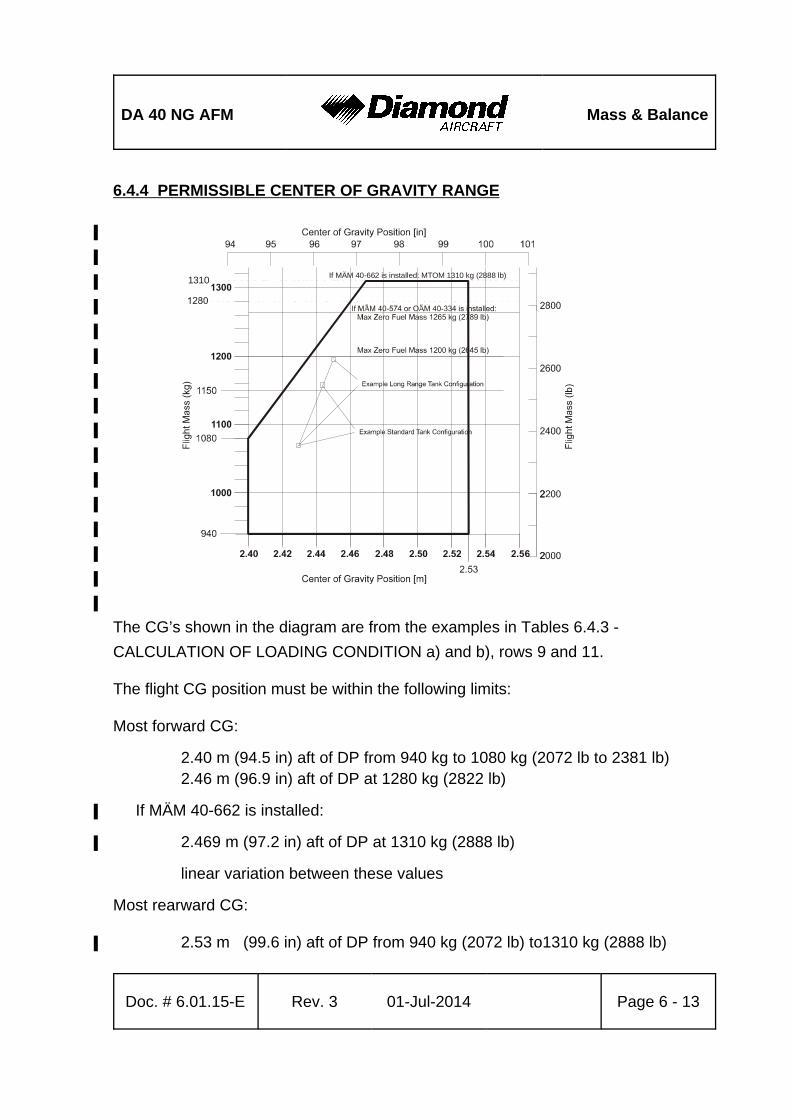
DA 40 NG AFM Mass & Balance
Doc. # 6.01.15-E Rev. 3 01-Jul-2014 Page 6 - 13
6.4.4 PERMISSIBLE CENTER OF GRAVITY RANGE
%
%
%
%
%
%
%
%
%
%
%
%
%
%
%
%
The CG’s shown in the diagram are from the examples in Tables 6.4.3 -
CALCULATION OF LOADING CONDITION a) and b), rows 9 and 11.
The flight CG position must be within the following limits:
Most forward CG:
2.40 m (94.5 in) aft of DP from 940 kg to 1080 kg (2072 lb to 2381 lb)2.46 m (96.9 in) aft of DP at 1280 kg (2822 lb)
If MÄM 40-662 is installed:%
2.469 m (97.2 in) aft of DP at 1310 kg (2888 lb)%
linear variation between these values
Most rearward CG:
2.53 m (99.6 in) aft of DP from 940 kg (2072 lb) to1310 kg (2888 lb)%
1310If MÄM 40-662 is installed: MTOM 1310 kg (2888 lb)
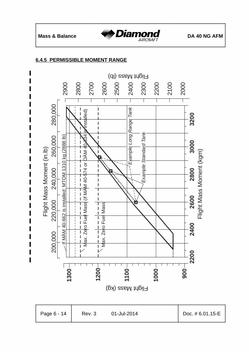
Mass & Balance DA 40 NG AFM
Page 6 - 14 Rev. 3 01-Jul-2014 Doc. # 6.01.15-E
6.4.5 PERMISSIBLE MOMENT RANGE
%
%
%
%
%
%
%
%
%
%
%
%
%
%
%
%
%
%
%
%
%
%
%
%
%
130
0
120
0
110
0
100
0
900
220
024
002
600
Flig
ht M
ass
Mom
ent (
kgm
)2
800
3000
320
0
Flight Mass (kg)
2500
2400
2300
2200
2100
2000
Flight Mass (lb)
200
,00
022
0,0
00
240
,000
260,
000
Flig
ht M
ass
Mom
ent (
in.lb
)
Ma
x. Z
ero
Fu
el M
ass
2600
2700
2800
2900
280,
000
Exa
mp
le S
tan
dard
Ta
nk
Exa
mpl
e L
ong
Ran
ge
Tan
k
Max
. Z
ero
Fue
l Ma
ss (
if M
ÄM
40
-57
4 or
OÄ
M 4
0-3
34
is in
sta
lled)
If M
ÄM
40
-66
2 is
inst
alle
d: M
TO
M 1
310
kg
(28
88 lb
)
DA 40 NG AFM Mass & Balance
Doc. # 6.01.15-E Rev. 3 01-Jul-2014 Page 6 - 15
6.5 EQUIPMENT LIST AND EQUIPMENT INVENTORY
All equipment approved for installation in the DA 40 NG is shown in the Equipment
List below.
The items of equipment installed in your particular airplane are indicated in the
appropriate column. The set of items marked as 'installed' constitutes the Equipment
Inventory.
NOTE
The equipment listed below cannot be installed in any
arbitrary combination. The airplane manufacturer must be
contacted before removing or installing equipment, with the
exception of replacing a unit by an identical unit.

DA
40
NG
AF
MM
ass
and
Bal
ance
Doc
. No.
6.0
1.15
-ER
ev. 3
01-J
ul-2
014
Pag
e 6
- 16
Airp
lane
Ser
ial N
o.:
Reg
istr
atio
n:D
ate:
Mas
sLe
ver A
rmD
escr
iptio
nTy
pePa
rt N
o.M
anuf
actu
rer
S/N
inst
alle
dlb
kgin
mAV
IONI
CS C
OOLI
NGAv
ioni
cs c
oolin
g fa
nSA
FE 3
2830
5 46
7-00
Sand
ia A
eros
pace
Avio
nics
coo
ling
fan
Cyc
lone
21-
3C
RB-
1222
53Lo
ne S
tar A
viat
ion
PFD
coo
ling
fan
SAFE
128
305
468-
00Sa
ndia
Aer
ospa
ce
MFD
coo
ling
fan
SAFE
128
305
468-
00Sa
ndia
Aer
ospa
ce
AUTO
PILO
T SY
STEM
Pitc
h se
rvo
GSA
81
011-
0087
8-00
Gar
min
Pitc
h se
rvo
%G
SA 8
1%
011-
0087
8-20
%G
arm
in%% %%%%%
Pitc
h se
rvo
mou
ntG
SM 8
501
1-00
894-
07G
arm
in
Pitc
h se
rvo
mou
nt%
GSM
86
%01
1-01
904-
03%
Gar
min
%% %%%%%Pi
tch
clut
ch c
artri
dge
%%01
1-02
147-
15%
Gar
min
%% %%%%%R
oll s
ervo
GSA
81
011-
0087
8-00
Gar
min
Rol
l ser
vo%
GSA
81
%01
1-00
878-
20%
Gar
min
%% %%%%%R
oll s
ervo
mou
ntG
SM 8
501
1-00
894-
07G
arm
in
Rol
l ser
vo m
ount
%G
SM 8
6%
011-
0190
4-03
%G
arm
in%% %%%%%
Rol
l clu
tch
cartr
idge
%%01
1-02
147-
08%
Gar
min
%% %%%%%Pi
tch
trim
ser
voG
SA 8
101
1-00
878-
00G
arm
in
Pitc
h tri
m s
ervo
%G
SA 8
1%
011-
0087
8-20
%G
arm
in%% %%%%%
Pitc
h tri
m s
ervo
mou
ntG
SM 8
501
1-00
894-
04G
arm
in
Pitc
h tri
m s
ervo
mou
nt%
GSM
86
%01
1-01
904-
03%
Gar
min
%% %%%%%Pi
tch
trim
clu
tch
cartr
idge
%%01
1-02
147-
15%
Gar
min
%% %%%%%C
ontro
l stic
kD
A4-2
213-
12-9
0D
iam
ond
Airc
raft
CW
S sw
itch
031-
0051
4-00
00Be
ndix
/Kin
g
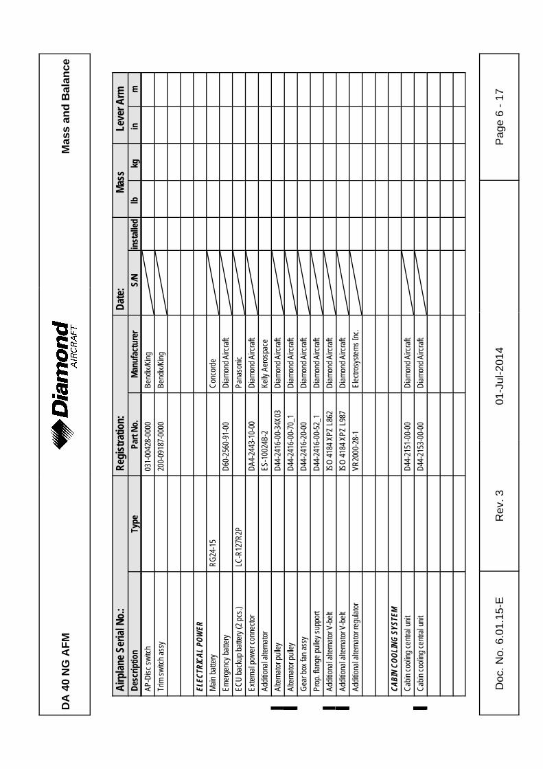
DA
40
NG
AF
MM
ass
and
Bal
ance
Airp
lane
Ser
ial N
o.:
Reg
istr
atio
n:D
ate:
Mas
sLe
ver A
rmD
escr
iptio
nTy
pePa
rt N
o.M
anuf
actu
rer
S/N
inst
alle
dlb
kgin
m
Doc
. No.
6.0
1.15
-ER
ev. 3
01-J
ul-2
014
Pag
e 6
- 17
AP-D
isc
switc
h03
1-00
428-
0000
Bend
ix/K
ing
Trim
sw
itch
assy
200-
0918
7-00
00Be
ndix
/Kin
g
ELEC
TRIC
AL P
OWER
Mai
n ba
ttery
RG
24-1
5C
onco
rde
Emer
genc
y ba
ttery
D60
-256
0-91
-00
Dia
mon
d Ai
rcra
ft
ECU
bac
kup
batte
ry (2
pcs
.)LC
-R12
7R2P
Pana
soni
c
Exte
rnal
pow
er c
onne
ctor
DA4
-244
3-10
-00
Dia
mon
d Ai
rcra
ft
Addi
tiona
l alte
rnat
orES
-100
24B-
2Ke
lly A
eros
pace
Alte
rnat
or p
ulle
yD
44-2
416-
00-3
4X03
%D
iam
ond
Airc
raft
Alte
rnat
or p
ulle
y%%
D44
-241
6-00
-70_
1%
Dia
mon
d Ai
rcra
ft%% %%%%%
Gea
r box
fan
assy
D44
-241
6-20
-00
Dia
mon
d Ai
rcra
ft
Prop
. fla
nge
pulle
y su
ppor
tD
44-2
416-
00-5
2_1
Dia
mon
d Ai
rcra
ft
Addi
tiona
l alte
rnat
or V
-bel
tIS
O 4
184
XPZ
L862
%D
iam
ond
Airc
raft
Addi
tiona
l alte
rnat
or V
-bel
t%%
ISO
418
4 XP
Z L9
87%
Dia
mon
d Ai
rcra
ft%% %%%%%
Addi
tiona
l alte
rnat
or re
gula
tor
VR20
00-2
8-1
Elec
trosy
stem
s In
c.
CABI
N CO
OLIN
G SY
STEM
Cab
in c
oolin
g ce
ntra
l uni
tD
44-2
151-
00-0
0D
iam
ond
Airc
raft
Cab
in c
oolin
g ce
ntra
l uni
t%%
D44
-215
3-00
-00
%D
iam
ond
Airc
raft
%% %%%%%
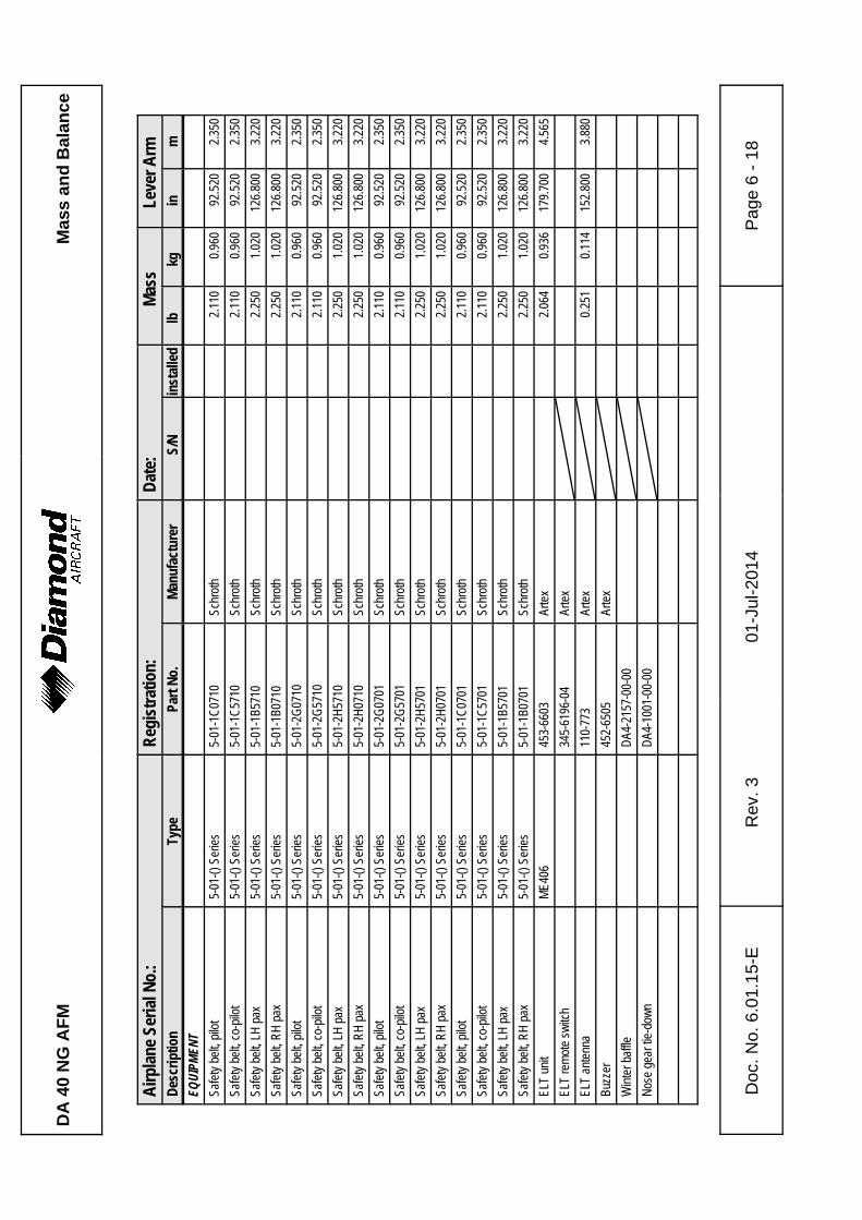
DA
40
NG
AF
MM
ass
and
Bal
ance
Airp
lane
Ser
ial N
o.:
Reg
istr
atio
n:D
ate:
Mas
sLe
ver A
rmD
escr
iptio
nTy
pePa
rt N
o.M
anuf
actu
rer
S/N
inst
alle
dlb
kgin
m
Doc
. No.
6.0
1.15
-ER
ev. 3
01-J
ul-2
014
Pag
e 6
- 18
EQUI
PMEN
TSa
fety
bel
t, pi
lot
5-01
-() S
erie
s5-
01-1
C07
10Sc
hrot
h2.
110
0.96
092
.520
2.35
0
Safe
ty b
elt,
co-p
ilot
5-01
-() S
erie
s5-
01-1
C57
10Sc
hrot
h2.
110
0.96
092
.520
2.35
0
Safe
ty b
elt,
LH p
ax5-
01-()
Ser
ies
5-01
-1B5
710
Schr
oth
2.25
01.
020
126.
800
3.22
0
Safe
ty b
elt,
RH
pax
5-01
-() S
erie
s5-
01-1
B071
0Sc
hrot
h2.
250
1.02
012
6.80
03.
220
Safe
ty b
elt,
pilo
t5-
01-()
Ser
ies
5-01
-2G
0710
Schr
oth
2.11
00.
960
92.5
202.
350
Safe
ty b
elt,
co-p
ilot
5-01
-() S
erie
s5-
01-2
G57
10Sc
hrot
h2.
110
0.96
092
.520
2.35
0
Safe
ty b
elt,
LH p
ax5-
01-()
Ser
ies
5-01
-2H
5710
Schr
oth
2.25
01.
020
126.
800
3.22
0
Safe
ty b
elt,
RH
pax
5-01
-() S
erie
s5-
01-2
H07
10Sc
hrot
h2.
250
1.02
012
6.80
03.
220
Safe
ty b
elt,
pilo
t5-
01-()
Ser
ies
5-01
-2G
0701
Schr
oth
2.11
00.
960
92.5
202.
350
Safe
ty b
elt,
co-p
ilot
5-01
-() S
erie
s5-
01-2
G57
01Sc
hrot
h2.
110
0.96
092
.520
2.35
0
Safe
ty b
elt,
LH p
ax5-
01-()
Ser
ies
5-01
-2H
5701
Schr
oth
2.25
01.
020
126.
800
3.22
0
Safe
ty b
elt,
RH
pax
5-01
-() S
erie
s5-
01-2
H07
01Sc
hrot
h2.
250
1.02
012
6.80
03.
220
Safe
ty b
elt,
pilo
t5-
01-()
Ser
ies
5-01
-1C
0701
Schr
oth
2.11
00.
960
92.5
202.
350
Safe
ty b
elt,
co-p
ilot
5-01
-() S
erie
s5-
01-1
C57
01Sc
hrot
h2.
110
0.96
092
.520
2.35
0
Safe
ty b
elt,
LH p
ax5-
01-()
Ser
ies
5-01
-1B5
701
Schr
oth
2.25
01.
020
126.
800
3.22
0
Safe
ty b
elt,
RH
pax
5-01
-() S
erie
s5-
01-1
B070
1Sc
hrot
h2.
250
1.02
012
6.80
03.
220
ELT
unit
ME4
0645
3-66
03Ar
tex
2.06
40.
936
179.
700
4.56
5
ELT
rem
ote
switc
h34
5-61
96-0
4Ar
tex
ELT
ante
nna
110-
773
Arte
x0.
251
0.11
415
2.80
03.
880
Buzz
er45
2-65
05Ar
tex
Win
ter b
affle
DA4
-215
7-00
-00
Nos
e ge
ar ti
e-do
wn
DA4
-100
1-00
-00
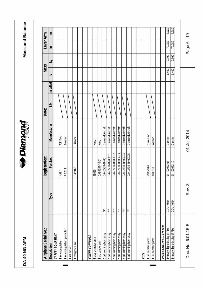
DA
40
NG
AF
MM
ass
and
Bal
ance
Airp
lane
Ser
ial N
o.:
Reg
istr
atio
n:D
ate:
Mas
sLe
ver A
rmD
escr
iptio
nTy
pePa
rt N
o.M
anuf
actu
rer
S/N
inst
alle
dlb
kgin
m
Doc
. No.
6.0
1.15
-ER
ev. 3
01-J
ul-2
014
Pag
e 6
- 19
SAFE
TY E
QUIP
MENT
Fire
ext
ingu
ishe
rH
AL 1
AIR
Tot
al
Fire
ext
ingu
ishe
r, po
rtabl
e 1
%%A
620
T%
Amer
ex%% %%%%%
Firs
t aid
kit
Emer
genc
y ax
eG
4591
2Fi
skar
s
FLIG
HT C
ONTR
OLS
Flap
s ac
tuat
or a
ssy
4305
5Kr
utz
Flap
con
trol u
nit
DAI
-903
1-10
-01
Krut
z
Stal
l war
ning
hor
n as
sy“A
”D
A4-2
739-
10-0
0D
iam
ond
Airc
raft
Stal
l war
ning
hor
n as
sy“B
”D
A4-2
739-
10-0
0X01
Dia
mon
d Ai
rcra
ft
Stal
l war
ning
hor
n as
sy“C
”D
A4-2
739-
10-0
0X02
Dia
mon
d Ai
rcra
ft
Stal
l war
ning
hor
n as
sy“D
”D
A4-2
739-
10-0
0X03
Dia
mon
d Ai
rcra
ft
Stal
l war
ning
hor
n as
sy“E
”D
A4-2
739-
10-0
0X04
Dia
mon
d Ai
rcra
ft
Stal
l war
ning
hor
n as
sy“F
”D
A4-2
739-
10-0
0X05
Dia
mon
d Ai
rcra
ft
FUEL
Fuel
tran
sfer
pum
p51
00-0
0-9
Duk
es In
c.
Fuel
tran
sfer
pum
p%%
1800
2-B
%W
eldo
n%% %%%%%
INDI
CATI
NG / R
EC. S
YSTE
MPr
imar
y fli
ght d
ispl
ay (P
FD)
GD
U 1
040
011-
0097
2-03
Gar
min
6.40
02.
900
70.0
801.
780
Prim
ary
fligh
t dis
play
(PFD
)G
DU
104
001
1-00
972-
10G
arm
in6.
400
2.90
070
.080
1.78
0
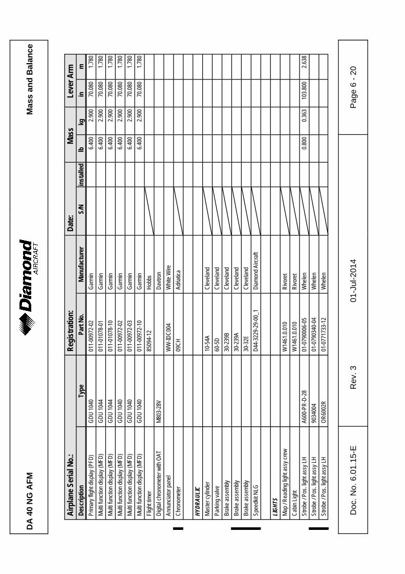
DA
40
NG
AF
MM
ass
and
Bal
ance
Airp
lane
Ser
ial N
o.:
Reg
istr
atio
n:D
ate:
Mas
sLe
ver A
rmD
escr
iptio
nTy
pePa
rt N
o.M
anuf
actu
rer
S/N
inst
alle
dlb
kgin
m
Doc
. No.
6.0
1.15
-ER
ev. 3
01-J
ul-2
014
Pag
e 6
- 20
Prim
ary
fligh
t dis
play
(PFD
)G
DU
104
001
1-00
972-
02G
arm
in6.
400
2.90
070
.080
1.78
0
Mul
ti fu
nctio
n di
spla
y (M
FD)
GD
U 1
044
011-
0107
8-01
Gar
min
6.40
02.
900
70.0
801.
780
Mul
ti fu
nctio
n di
spla
y (M
FD)
GD
U 1
044
011-
0107
8-10
Gar
min
6.40
02.
900
70.0
801.
780
Mul
ti fu
nctio
n di
spla
y (M
FD)
GD
U 1
040
011-
0097
2-02
Gar
min
6.40
02.
900
70.0
801.
780
Mul
ti fu
nctio
n di
spla
y (M
FD)
GD
U 1
040
011-
0097
2-03
Gar
min
6.40
02.
900
70.0
801.
780
Mul
ti fu
nctio
n di
spla
y (M
FD)
GD
U 1
040
011-
0097
2-10
Gar
min
6.40
02.
900
70.0
801.
780
Flig
ht ti
mer
8509
4-12
Hob
bs
Dig
ital c
hron
omet
er w
ith O
ATM
803-
28V
Dav
tron
Annu
ncia
tor p
anel
WW
-IDC
004
Whi
te W
ire
Chr
onom
eter
%%09
CH
%Ad
riatic
a%% %%%%%
HYDR
AULI
CM
aste
r cyl
inde
r10
-54A
Cle
vela
nd
Park
ing
valv
e60
-5D
Cle
vela
nd
Brak
e as
sem
bly
30-2
39B
Cle
vela
nd
Brak
e as
sem
bly
%%30
-239
A%
Cle
vela
nd%
Brak
e as
sem
bly
%%30
-32E
%C
leve
land
%%%%%%%Sp
eedk
it N
LG%%
D44
-322
9-29
-00_
1%
Dia
mon
d Ai
rcra
ft%% %%%%%
LIGH
TSM
ap /
Rea
ding
ligh
t ass
y cr
ewW
1461
.0.0
10R
ivor
et
Cab
in L
ight
W14
61.0
.010
Riv
oret
Stro
be /
Pos.
ligh
t ass
y LH
A600
-PR
-D-2
801
-079
0006
-05
Whe
len
0.80
00.
363
103.
800
2.63
8
Stro
be /
Pos.
ligh
t ass
y LH
%90
3400
4%
01-0
7903
40-0
4%
Whe
len
%% %%%%%St
robe
/ Po
s. li
ght a
ssy
LH%
OR
6002
R%
01-0
7717
33-1
2%
Whe
len
%% %%%%%
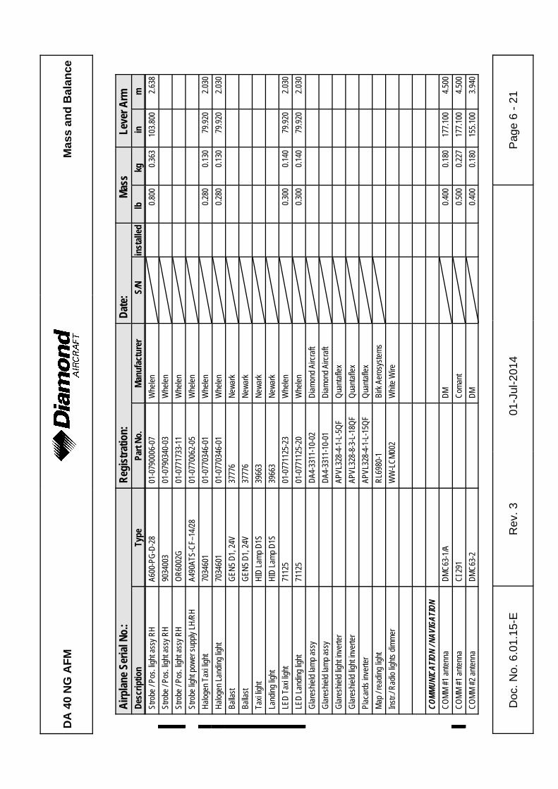
DA
40
NG
AF
MM
ass
and
Bal
ance
Airp
lane
Ser
ial N
o.:
Reg
istr
atio
n:D
ate:
Mas
sLe
ver A
rmD
escr
iptio
nTy
pePa
rt N
o.M
anuf
actu
rer
S/N
inst
alle
dlb
kgin
m
Doc
. No.
6.0
1.15
-ER
ev. 3
01-J
ul-2
014
Pag
e 6
- 21
Stro
be /
Pos.
ligh
t ass
y R
HA6
00-P
G-D
-28
01-0
7900
06-0
7W
hele
n0.
800
0.36
310
3.80
02.
638
Stro
be /
Pos.
ligh
t ass
y R
H%
9034
003
%01
-079
0340
-03
%W
hele
n%% %%%%%
Stro
be /
Pos.
ligh
t ass
y R
H%
OR
6002
G%
01-0
7717
33-1
1%
Whe
len
%% %%%%%St
robe
ligh
t pow
er s
uppl
y LH
/RH
A490
ATS-
CF–
14/2
801
-077
0062
-05
Whe
len
Hal
ogen
Tax
i lig
ht%
7034
601
01-0
7703
46-0
1W
hele
n0.
280
%0.
130
%79
.920
2.03
0
Hal
ogen
Lan
ding
ligh
t%
7034
601
01-0
7703
46-0
1W
hele
n0.
280
%0.
130
%79
.920
2.03
0
Balla
st%
GEN
5 D
1, 2
4V%
3777
6%
New
ark
%% %%%%%Ba
llast
%G
EN5
D1,
24V
%37
776
%N
ewar
k%% %%%%%
Taxi
ligh
t%
HID
Lam
p D
1S%
3966
3%
New
ark
%% %%%%%La
ndin
g lig
ht%
HID
Lam
p D
1S%
3966
3%
New
ark
%% %%%%%LE
D T
axi l
ight
%71
125
%01
-077
1125
-23
%W
hele
n%% %
0.30
0%
0.14
0%
79.9
20%
2.03
0%
LED
Lan
ding
ligh
t%
7112
5%
01-0
7711
25-2
0%
Whe
len
%% %0.
300
%0.
140
%79
.920
%2.
030
%G
lare
shie
ld la
mp
assy
DA4
-331
1-10
-02
Dia
mon
d Ai
rcra
ft
Gla
resh
ield
lam
p as
syD
A4-3
311-
10-0
1D
iam
ond
Airc
raft
Gla
resh
ield
ligh
t inv
erte
rAP
VL32
8-4-
1-L-
5QF
Qua
ntaf
lex
Gla
resh
ield
ligh
t inv
erte
rAP
VL32
8-8-
3-L-
18Q
FQ
uant
afle
x
Plac
ards
inve
rter
APVL
328-
4-1-
L-15
QF
Qua
ntaf
lex
Map
/ re
adin
g lig
htR
L698
0-1
Birk
Aer
osys
tem
s
Inst
r./ R
adio
ligh
ts d
imm
erW
W-L
CM
002
Whi
te W
ire
COMM
UNIC
ATIO
N / N
AVIG
ATIO
NC
OM
M #
1 an
tenn
aD
MC
63-1
/AD
M0.
400
0.18
017
7.10
04.
500
CO
MM
#1
ante
nna
%C
I 291
%%C
oman
t%% %
0.50
0%
0.22
7%
177.
100
%4.
500
%C
OM
M #
2 an
tenn
aD
MC
63-2
DM
0.40
00.
180
155.
100
3.94
0
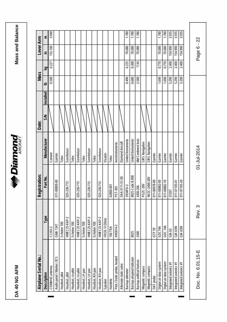
DA
40
NG
AF
MM
ass
and
Bal
ance
Airp
lane
Ser
ial N
o.:
Reg
istr
atio
n:D
ate:
Mas
sLe
ver A
rmD
escr
iptio
nTy
pePa
rt N
o.M
anuf
actu
rer
S/N
inst
alle
dlb
kgin
m
Doc
. No.
6.0
1.15
-ER
ev. 3
01-J
ul-2
014
Pag
e 6
- 22
CO
MM
#2
ante
nna
%C
I 292
-2%%
Com
ant
%% %0.
500
%0.
227
%15
5.10
0%
3.94
0%
Audi
o pa
nel /
Mar
ker /
ICS
GM
A 13
4701
1-00
809-
00G
arm
in
Hea
dset
, pilo
tEc
helo
n 10
0Te
lex
Hea
dset
, pilo
tH
MEC
25-K
AP-2
025-
230-
715
Senn
heis
er
Hea
dset
, co-
pilo
tEc
helo
n 10
0Te
lex
Hea
dset
, co-
pilo
tH
MEC
25-K
AP-2
025-
230-
715
Senn
heis
er
Hea
dset
, LH
pax
Eche
lon
100
Tele
x
Hea
dset
, LH
pax
HM
EC25
-KAP
-202
5-23
0-71
5Se
nnhe
iser
Hea
dset
, RH
pax
Eche
lon
100
Tele
x
Hea
dset
, RH
pax
HM
EC25
-KAP
-202
5-23
0-71
5Se
nnhe
iser
Spea
ker
FRS8
/ 4
Ohm
sVi
sato
n
Han
dmic
100
TRA
6280
0-00
1Te
lex
Pito
t / S
tatic
pro
be, h
eate
dAN
5814
-2PS
T-30
5Ae
roin
stru
men
ts
Alte
rnat
e st
atic
val
veD
A4-3
111-
51-0
0D
iam
ond
Airc
raft
Back
up a
ltim
eter
5934
PD-3
Uni
ted
Inst
rum
ents
0.49
60.
225
70.0
801.
780
Back
up a
irspe
ed in
dica
tor
8025
8025
Cod
e B.
908
%U
nite
d In
stru
men
ts0.
680
0.30
870
.080
1.78
0
Back
up a
rtific
ial h
oriz
on43
0043
00-2
06M
id C
ontin
ent I
nstr.
2.50
011
3470
.080
1.78
0
Mag
netic
com
pass
PG2C
-28V
SIR
S N
avig
atio
n
Mag
netic
com
pass
%%N
V2C
-240
0-28
V%
SIR
S N
avig
atio
n%% %%%%%
OAT
pro
beG
TP 5
901
1-00
978-
00G
arm
in
Dig
ital a
ir da
ta s
yste
mG
DC
74A
011-
0088
2-00
Gar
min
1.69
00.
770
70.0
801.
780
Dig
ital a
ir da
ta s
yste
mG
DC
74A
011-
0088
2-10
Gar
min
1.69
00.
770
70.0
801.
780
Inte
grat
ed a
vion
ics
#1G
IA 6
337
207
Gar
min
5.29
02.
400
154.
900
3.93
5
Inte
grat
ed a
vion
ics
#1G
IA 6
3W01
1-01
105-
01G
arm
in5.
290
2.40
015
4.90
03.
935
Inte
grat
ed a
vion
ics
#1%
GIA
63W
%01
1-01
105-
20%
Gar
min
%% %5.
290
%2.
400
%15
4.90
0%
3.93
5%
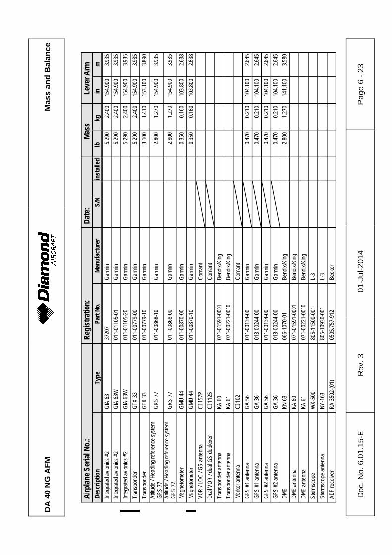
DA
40
NG
AF
MM
ass
and
Bal
ance
Airp
lane
Ser
ial N
o.:
Reg
istr
atio
n:D
ate:
Mas
sLe
ver A
rmD
escr
iptio
nTy
pePa
rt N
o.M
anuf
actu
rer
S/N
inst
alle
dlb
kgin
m
Doc
. No.
6.0
1.15
-ER
ev. 3
01-J
ul-2
014
Pag
e 6
- 23
Inte
grat
ed a
vion
ics
#2G
IA 6
337
207
Gar
min
5.29
02.
400
154.
900
3.93
5
Inte
grat
ed a
vion
ics
#2G
IA 6
3W01
1-01
105-
01G
arm
in5.
290
2.40
015
4.90
03.
935
Inte
grat
ed a
vion
ics
#2%
GIA
63W
%01
1-01
105-
20%
Gar
min
%% %5.
290
%2.
400
%15
4.90
0%
3.93
5%
Tran
spon
der
%G
TX 3
3%
011-
0077
9-00
%G
arm
in%% %
5.29
0%
2.40
0%
154.
900
%3.
935
%Tr
ansp
onde
rG
TX 3
301
1-00
779-
10G
arm
in3.
100
1.41
015
3.10
03.
890
Attit
ude
/ Hea
ding
refe
renc
e sy
stem
GR
S 77
GR
S 77
011-
0086
8-10
Gar
min
2.80
01.
270
154.
900
3.93
5
Attit
ude
/ Hea
ding
refe
renc
e sy
stem
GR
S 77
GR
S 77
011-
0086
8-00
Gar
min
2.80
01.
270
154.
900
3.93
5
Mag
neto
met
erG
MU
44
011-
0087
0-00
Gar
min
0.35
00.
160
103.
800
2.63
8
Mag
neto
met
er%
GM
U 4
4%
011-
0087
0-10
%G
arm
in%% %
0.35
0%
0.16
0%
103.
800
%2.
638
%VO
R /
LOC
/ G
S an
tenn
aC
I 157
PC
oman
t
Dua
l VO
R /
dual
GS
dupl
exer
CI 1
125
Com
ant
Tran
spon
der a
nten
naKA
60
071-
0159
1-00
01Be
ndix
/Kin
g
Tran
spon
der a
nten
naKA
61
071-
0022
1-00
10Be
ndix
/Kin
g
Mar
ker a
nten
naC
I 102
Com
ant
GPS
#1
ante
nna
GA
5601
1-00
134-
00G
arm
in0.
470
0.21
010
4.10
02.
645
GPS
#1
ante
nna
GA
3601
3-00
244-
00G
arm
in0.
470
0.21
010
4.10
02.
645
GPS
#2
ante
nna
GA
5601
1-00
134-
00G
arm
in0.
470
0.21
010
4.10
02.
645
GPS
#2
ante
nna
GA
3601
3-00
244-
00G
arm
in0.
470
0.21
010
4.10
02.
645
DM
EKN
63
066-
1070
-01
Bend
ix/K
ing
2.80
01.
270
141.
100
3.58
0
DM
E an
tenn
aKA
60
071-
0159
1-00
01Be
ndix
/Kin
g
DM
E an
tenn
aKA
61
071-
0022
1-00
10Be
ndix
/Kin
g
Stor
msc
ope
WX-
500
805-
1150
0-00
1L-
3
Stor
msc
ope
ante
nna
NY-
163
805-
1093
0-00
1L-
3
ADF
rece
iver
RA
3502
-(01)
0505
.757
-912
Beck
er
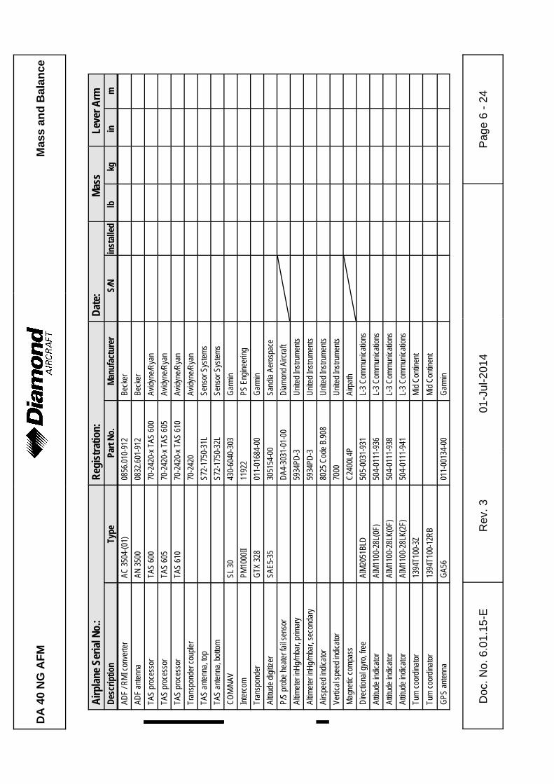
DA
40
NG
AF
MM
ass
and
Bal
ance
Airp
lane
Ser
ial N
o.:
Reg
istr
atio
n:D
ate:
Mas
sLe
ver A
rmD
escr
iptio
nTy
pePa
rt N
o.M
anuf
actu
rer
S/N
inst
alle
dlb
kgin
m
Doc
. No.
6.0
1.15
-ER
ev. 3
01-J
ul-2
014
Pag
e 6
- 24
ADF
/ RM
I con
verte
rAC
350
4-(0
1)08
56.0
10-9
12Be
cker
ADF
ante
nna
AN 3
500
0832
.601
-912
Beck
er
TAS
proc
esso
r%
TAS
600
%70
-242
0-x
TAS
600
%Av
idyn
e/R
yan
%% %%%%%TA
S pr
oces
sor
%TA
S 60
5%
70-2
420-
x TA
S 60
5%
Avid
yne/
Rya
n%% %%%%%
TAS
proc
esso
r%
TAS
610
%70
-242
0-x
TAS
610
%Av
idyn
e/R
yan
%% %%%%%Tr
ansp
onde
r cou
pler
%%70
-242
0%
Avid
yne/
Rya
n%% %%%%%
TAS
ante
nna,
top
%%S7
2-17
50-3
1L%
Sens
or S
yste
ms
%% %%%%%TA
S an
tenn
a, b
otto
m%%
S72-
1750
-32L
%Se
nsor
Sys
tem
s%% %%%%%
CO
M/N
AVSL
30
430-
6040
-303
Gar
min
Inte
rcom
PM10
00II
1192
2PS
Eng
inee
ring
Tran
spon
der
GTX
328
011-
0168
4-00
Gar
min
Altit
ude
digi
tizer
SAE5
-35
3051
54-0
0Sa
ndia
Aer
ospa
ce
P/S
prob
e he
ater
fail
sens
orD
A4-3
031-
01-0
0D
iam
ond
Airc
raft
Altim
eter
inH
g/m
bar,
prim
ary
5934
PD-3
Uni
ted
Inst
rum
ents
Altim
eter
inH
g/m
bar,
seco
ndar
y59
34PD
-3U
nite
d In
stru
men
ts
Airs
peed
indi
cato
r80
25 C
ode
B.90
8%
Uni
ted
Inst
rum
ents
Verti
cal s
peed
indi
cato
r70
00U
nite
d In
stru
men
ts
Mag
netic
com
pass
C24
00L4
PAi
rpat
h
Dire
ctio
nal g
yro,
free
AIM
2051
BLD
505-
0031
-931
L-3
Com
mun
icat
ions
Attit
ude
indi
cato
rAI
M11
00-2
8L(0
F)50
4-01
11-9
36L-
3 C
omm
unic
atio
ns
Attit
ude
indi
cato
rAI
M11
00-2
8LK(
0F)
504-
0111
-938
L-3
Com
mun
icat
ions
Attit
ude
indi
cato
rAI
M11
00-2
8LK(
2F)
504-
0111
-941
L-3
Com
mun
icat
ions
Turn
coo
rdin
ator
1394
T100
-3Z
Mid
Con
tinen
t
Turn
coo
rdin
ator
1394
T100
-12R
BM
id C
ontin
ent
GPS
ant
enna
GA5
601
1-00
134-
00G
arm
in
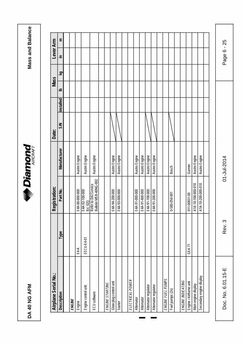
DA
40
NG
AF
MM
ass
and
Bal
ance
Airp
lane
Ser
ial N
o.:
Reg
istr
atio
n:D
ate:
Mas
sLe
ver A
rmD
escr
iptio
nTy
pePa
rt N
o.M
anuf
actu
rer
S/N
inst
alle
dlb
kgin
m
Doc
. No.
6.0
1.15
-ER
ev. 3
01-J
ul-2
014
Pag
e 6
- 25
ENGI
NEEn
gine
E4-A
E4A-
00-0
00-0
00Au
stro
Eng
ine
Engi
ne c
ontro
l uni
tEE
CU
-E4-
01E4
A-92
-100
-000
Iss:
02(
)Au
stro
Eng
ine
ECU
sof
twar
eR
efer
to D
AI S
ervi
ceBu
lletin
MSB
-40N
G-0
02Au
stro
Eng
ine
ENGI
NE S
TART
ING
Glo
w p
lug
cont
rol u
nit
E4A-
94-2
00-0
00Au
stro
Eng
ine
Star
ter
E4A-
93-0
00-0
00Au
stro
Eng
ine
ELEC
TRIC
AL P
OWER
Alte
rnat
orE4
A-91
-000
-000
Aust
ro E
ngin
e
Alte
rnat
or%%
E4A-
91-4
00-0
00%
Aust
ro E
ngin
e%% %%%%%
Alte
rnat
or re
gula
tor
E4A-
91-1
00-0
00Au
stro
Eng
ine
Alte
rnat
or re
gula
tor
%%E4
A-91
-200
-000
%Au
stro
Eng
ine
%%
ENGI
NE F
UEL
PUM
PSFu
el p
umps
(2x)
0-58
0-05
4-00
1Bo
sch
ENGI
NE IN
DICA
TING
Engi
ne /
Airfr
ame
unit
GEA
71
011-
0083
1-00
Gar
min
Mai
n en
gine
dis
play
A1A-
10-1
00-0
00-0
10Au
stro
Eng
ine
Seco
ndar
y en
gine
dis
play
A1A-
10-2
00-0
00-0
10Au
stro
Eng
ine
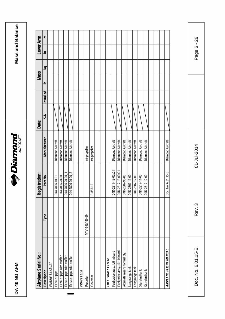
DA
40
NG
AF
MM
ass
and
Bal
ance
Airp
lane
Ser
ial N
o.:
Reg
istr
atio
n:D
ate:
Mas
sLe
ver A
rmD
escr
iptio
nTy
pePa
rt N
o.M
anuf
actu
rer
S/N
inst
alle
dlb
kgin
m
Doc
. No.
6.0
1.15
-ER
ev. 3
01-J
ul-2
014
Pag
e 6
- 26
ENGI
NE E
XHAU
STEx
haus
t pip
eD
44-7
806-
10-0
1D
iam
ond
Airc
raft
Exha
ust p
ipe
with
muf
fler
D44
-780
6-20
-00
Dia
mon
d Ai
rcra
ftEx
haus
t pip
e w
ith m
uffle
rD
44-7
806-
20-0
0_1
Dia
mon
d Ai
rcra
ftEx
haus
t pip
e w
ith m
uffle
r%%
D44
-780
6-20
-00_
2%
Dia
mon
d Ai
rcra
ft%% %%%%%
PROP
ELLE
RPr
opel
ler
MTV
-6-R
/190
-69
mt-p
rope
ller
Gov
erno
rP-
853-
16m
t-pro
pelle
r
FUEL
TAN
K SY
STEM
Fuel
pro
be a
ssy.
, LH
inbo
ard
D4D
-281
7-13
-00x
01D
iam
ond
Airc
raft
Fuel
pro
be a
ssy.
, RH
inbo
ard
D4D
-281
7-13
-00x
01D
iam
ond
Airc
raft
Alte
rnat
e m
eans
for f
uel q
ty.
D4D
-280
7-90
-00
Dia
mon
d Ai
rcra
ft
Long
rang
e ta
nkD
4D-2
807-
11-0
0D
iam
ond
Airc
raft
Long
rang
e ta
nkD
4D-2
807-
12-0
0D
iam
ond
Airc
raft
Stan
dard
tank
D4D
-281
7-11
-00
Dia
mon
d Ai
rcra
ft
Stan
dard
tank
D4D
-281
7-12
-00
Dia
mon
d Ai
rcra
ft
AIRP
LANE
FLI
GHT
MANU
ALD
oc. N
o. 6
.01.
15-E
Dia
mon
d Ai
rcra
ft
DA
40
NG
AF
MM
ass
and
Bal
ance
Doc
. No.
6.0
1.15
-ER
ev. 3
01-J
ul-2
014
Pag
e 6
- 27
1.A
mer
ex A
620T
is
UL
appr
oved
and
can
be
used
in
airc
raft
regi
ster
ed i
n C
anad
a an
d th
e U
SA
. F
or a
ircra
ft re
gist
ered
in
othe
r%
coun
trie
s, c
onta
ct th
e lo
cal a
irwor
thin
ess
auth
ority
.%
Plac
e: _
____
____
____
____
____
__D
ate:
___
____
____
____
____
____
____
Sign
atur
e: _
____
____
____
____
____
____
__
DA
40
NG
AF
MM
ass
and
Bal
ance
Doc
. No.
6.0
1.15
-ER
ev. 3
01-J
ul-2
014
Pag
e 6
- 28
Inte
ntio
nally
left
blan
k.
DA 40 NG AFMAirplane
Description
Doc. # 6.01.15-E Rev. 3 01-Jul-2014 Page 7 - 1
CHAPTER 7
DESCRIPTION OF THE AIRPLANE
AND ITS SYSTEMS
Page
7.1 INTRODUCTION . . . . . . . . . . . . . . . . . . . . . . . . . . . . . . . . . . . . . . . 7-2
7.2 AIRFRAME . . . . . . . . . . . . . . . . . . . . . . . . . . . . . . . . . . . . . . . . . . . 7-2
7.3 FLIGHT CONTROLS . . . . . . . . . . . . . . . . . . . . . . . . . . . . . . . . . . . . 7-3
7.4 INSTRUMENT PANEL . . . . . . . . . . . . . . . . . . . . . . . . . . . . . . . . . . 7-8
7.5 LANDING GEAR . . . . . . . . . . . . . . . . . . . . . . . . . . . . . . . . . . . . . . 7-14
7.6 SEATS AND SAFETY HARNESSES . . . . . . . . . . . . . . . . . . . . . . 7-16
7.7 BAGGAGE COMPARTMENT . . . . . . . . . . . . . . . . . . . . . . . . . . . . 7-18
7.8 CANOPY, REAR DOOR, AND CABIN INTERIOR . . . . . . . 7-18
7.9 POWER PLANT . . . . . . . . . . . . . . . . . . . . . . . . . . . . . . . . . . . . . . 7-21
7.9.1 ENGINE, GENERAL . . . . . . . . . . . . . . . . . . . . . . . . . . . . . . 7-21
7.9.2 OPERATING CONTROLS . . . . . . . . . . . . . . . . . . . . . . . . . 7-22
7.9.3 PROPELLER . . . . . . . . . . . . . . . . . . . . . . . . . . . . . . . . . . . . 7-25
7.9.4 FUEL SYSTEM . . . . . . . . . . . . . . . . . . . . . . . . . . . . . . . . . . 7-27
7.9.5 COOLING SYSTEM . . . . . . . . . . . . . . . . . . . . . . . . . . . . . . 7-35
7.9.6 TURBO CHARGER SYSTEM . . . . . . . . . . . . . . . . . . . . . . . 7-36
7.9.7 OIL SYSTEMS . . . . . . . . . . . . . . . . . . . . . . . . . . . . . . . . . . 7-37
7.10 ELECTRICAL SYSTEM . . . . . . . . . . . . . . . . . . . . . . . . . . . . . . . . 7-38
7.10.1 GENERAL . . . . . . . . . . . . . . . . . . . . . . . . . . . . . . . . . . . . . 7-39
7.10.2 ENGINE CONTROL UNIT / ECU . . . . . . . . . . . . . . . . . . . 7-46
7.11 PITOT-STATIC SYSTEM . . . . . . . . . . . . . . . . . . . . . . . . . . . . . . . 7-48
7.12 STALL WARNING SYSTEM . . . . . . . . . . . . . . . . . . . . . . . . . . . . . 7-48
Airplane
DescriptionDA 40 NG AFM
Page 7 - 2 Rev. 3 01-Jul-2014 Doc. # 6.01.15-E
7.1 INTRODUCTION
Chapter 7 contains a description of the airplane and its systems, together with operating
instructions.
For details about optional equipment see Chapter 9.
7.2 AIRFRAME
Fuselage
The GFRP fuselage is of semi monocoque molded construction. The fire protection on
the firewall is of a special fire-resistant matting, which is covered on the engine side by
stainless steel cladding. The two main bulkheads are GFRP/CFRP items.
Wings
The wings have a front and rear spar; each wing has a top shell and a bottom shell - a
'fail-safe' concept. The wings, as well as the ailerons and flaps, are made of GFRP/CFRP,
and are principally of sandwich construction. An aluminum fuel tank is installed in each
of the wings.
Empennage
The airplane has a 'T' tail of GFRP semi monocoque construction. Both the stabilizers
have twin spars and a skin with no sandwich. Rudder and elevator are of sandwich
construction.
DA 40 NG AFMAirplane
Description
Doc. # 6.01.15-E Rev. 3 01-Jul-2014 Page 7 - 3
7.3 FLIGHT CONTROLS
The ailerons, elevator and wing flaps are operated through control rods, while the rudder
is controlled by cables. The flaps are electrically operated. Elevator forces can be balanced
by a trim tab on the elevator, which is operated by a Bowden cable.
Ailerons
Construction: GFRP/CFRP composite sandwich.
Hinges: There are 4 hinges, which are hinge pins mounted in an aluminum
bracket. They are secured in position by a roll pin. The absence of this
roll pin can lead to the loss of the hinge pin and a consequent loss of flight
safety.
Operation: A rod-end bearing is screwed into a steel push rod and locked by means
of a jam nut which has locking varnish applied to it. Damage to this
varnish can indicate a twisting and thus a change to the adjustment. The
connection between the rod-end bearing and the control horn is a bolt,
the nut of which is likewise sealed with locking varnish.
The aluminum control horn is attached to the aileron with 3 screws.
Airplane
DescriptionDA 40 NG AFM
Page 7 - 4 Rev. 3 01-Jul-2014 Doc. # 6.01.15-E
Flaps
Construction: GFRP/CFRP composite sandwich.
Hinges: There are 6 hinges, which are hinge pins mounted in an aluminum
bracket. They are secured in position by a roll pin. The absence of this
roll pin can lead to the loss of the hinge pin and a consequent loss of flight
safety. Another aluminum fitting is located at the fuselage and is attached
to a torsion tube. The torsion tube is located in the fuselage, creating a
connection between the left and right flaps.
Operation: A rod-end bearing is screwed into a steel push rod and locked by means
of a jam nut which has locking varnish applied to it. Damage to this
varnish can indicate a twisting and thus a change to the adjustment. The
connection between the rod-end bearing and the control horn is a bolt,
the nut of which is likewise sealed with locking varnish.
The flap control horn is attached to the flap with 3 screws.
The flaps are driven by an electric motor and have 3 settings:
- Cruise (UP), totally retracted
- Take-off (T/O), and
- Landing (LDG).
DA 40 NG AFMAirplane
Description
Doc. # 6.01.15-E Rev. 3 01-Jul-2014 Page 7 - 5
The flaps are operated by means of a 3-position flap selector switch on the instrument
panel. The positions of the switch correspond to the positions of the flaps, the cruise
position of the switch being at the top. If the switch is moved to another position, the flaps
continue to travel automatically until they have reached the position selected on the switch.
The UP and LDG positions are additionally protected by a limit switch to guard against
over-running the end positions.
The electrical flap drive has an automatic circuit breaker which can also be operated
manually.
Flap Position Indicator:
The current flap position is indicated by means of three lights beside the flap selector
switch.
When the upper light (green) is illuminated, the flaps are in the cruise position (UP);
when the center light (white) is illuminated, the flaps are in take-off position (T/O);
when the lower light (white) is illuminated, the flaps are in landing position (LDG).
When two lights are illuminated simultaneously, the flaps are between the two indicated
positions. This is the case only when the flaps are traveling.
Airplane
DescriptionDA 40 NG AFM
Page 7 - 6 Rev. 3 01-Jul-2014 Doc. # 6.01.15-E
Elevator
Construction: GFRP sandwich.
Hinges: 5 hinges.
Operation: Steel push-rods;
Two of the bellcrank bearings are accessible to visual inspection next
to the lower hinge of the rudder. The elevator horn and its bearing, as
well as the connection to the push-rod, can be visually inspected at the
upper end of the rudder.
Rudder
Construction: GFRP sandwich.
Hinges: Upper hinge: One bolt.
Lower hinge: Bearing bracket including rudder stops, held by 4 screws
to the rear web of the vertical stabilizer. The mating part
on the rudder is a bracket which is attached to the rudder
by 2 bolts. The bolts and nuts are accessible to visual
inspection.
Operation: Steel cables, the eyes of which are connected to the bolts on the bracket.
DA 40 NG AFMAirplane
Description
Doc. # 6.01.15-E Rev. 3 01-Jul-2014 Page 7 - 7
Elevator Trim
The trim control is a black wheel in the center console to the rear of the power lever. To
guard against over-rotating, the trim wheel incorporates a friction device. A mark on the
wheel shows the take-off (T/O) position.
Turn wheel to the front = nose down
Turn wheel to the rear = nose up
Pedal Adjustment
NOTE
The pedals may only be adjusted on the ground!
The pedals are unlocked by pulling the black handle which is located behind the rear
attachment.
Forward Adjustment:
Whilst keeping the handle pulled, push the pedals forward with your feet. Release the
handle and allow the pedals to lock into place.
Rearward Adjustment:
Using the unlocking handle, pull the pedals back to the desired position. Release the
handle and push the pedals forward with your feet until they lock into place.
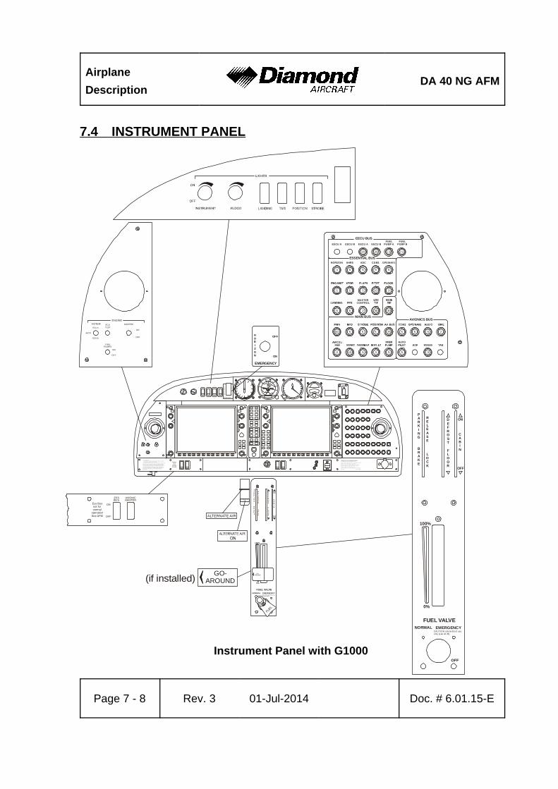
Airplane
DescriptionDA 40 NG AFM
Page 7 - 8 Rev. 3 01-Jul-2014 Doc. # 6.01.15-E
ALTERNATE AIR
ALTERNATE AIRON
ALTERNATE AIR
OFF
EMERGENCY
ON
HORIZON
OFF
EM ER G E N CY
ON
H
ORI
Z
ON
Ma n ou v eri ng sp e ed : = 111 K I A S (a b ov e 1 0 36 up t o 1 20 0 k g / a bo ve 2 28 4 u p t o 26 4 6 l b)
= 94 K I A S ( 7 8 0 t o 1 0 36 kg / 1 7 20 t o 2 28 4 lb )
T hi s a i rpl a ne ma y o nl y b e op era t e d i n a cc ord a nc e w i t h t h e A i rpl a ne F li g htMa n ua l . I t ca n b e o p era t ed in t he "No rma l" a n d "U t i li t y" c at e go r i es inn on -i ci ng co n di t io n s. P rov id e d t h at na t i on a l o pe ra ti o na l re q ui re me nt sa r e m et an d th e ap pro p ria t e e q ui p me nt i s i ns ta l le d , t h i s ai r p la n e i s a p-p r ov ed f or t h e f o ll ow in g k i nd s o f o p era t io n : d a y V F R, ni gh t V F R a n dI F R. A l l a ero b at i cs ma n eu ve rs i n cl ud i ng sp i nn i ng are pro h ib i te d . F o rf ur t h e r o p era t io n al li m it a t io ns ref e r t o t he A irp l an e F l i gh t M a nu al .No sm ok in g
V
V
A
A
Limitations for GFC 700 Aut opilo t System:D o n o t u s e A P i f “ A l t er n at e S ta t i c ” i s o p e n .
C o n d u c t A P a n d t r im c h e c k p ri o r t o e a ch f l i g ht ( se e A F M ).
A u t o p i lo t O F F d u r i n g t ak e -o f f a n d la n d i n g .M a xi m u m s pe e d f o r a u t o p il o t o p e ra t io n i s 16 5 K IA S .
M i n im u m s pe e d f o r a u t o p il o t o p e ra t io n i s 7 0 K I A S .M i n im u m a l ti t u d e f o r a u t op i l o t o pe r at i o n :
C r u is e , C l i m b , D e s ce n t a n d Ma n e u v e ri n g: 8 0 0 f e e t A G L
A p p r o a c h : 2 0 0 f e e t A G L
Ess Busnot fornormal
opera tionSee AFM
ECU A
FUELPUMPS
ON
OFF
ECUTEST
MASTER
ENGINE
ECU B
VOTER
AUTO
ON
OFF
ON
ESSBUS
AVIONICMASTER
OFF
Ess Busnot fornormal
operationSee AFM
EECU B
EECU BUS
MAIN BUSAVIONICS BUS
EECU A
GPS/NAV1
MASTERCONTROL
FUELPUMP A
COM1AHRS ADCHORIZON
EECU A EECU BFUEL
PUMP B
ESSENTIAL BUS
20
3
5
5
60
3
5
3
30
25
5
5
5
5 5
3
2
5
5
5
5
10
5
5
2
5
5
5
10
30
5
3
20 20
GO-AROUND
PARKING
BRAKE
RELEASE
LOCK
DEFROST
CABIN
ON
OFF
NORMAL
OFF
EMERGENCYCAU TION interm ittent useonly (s ee AF M)
FUEL VALVE
100%
0%
FLOOR
PARKI
NG
BRAKE
RELEASE
LOCK
DEFROST
CABI
N
ON
OF F
NORMAL
OFF
EMERGENCYC AU TION in term ittent useonly (see AFM)
FUEL VALVE
100%
0%
FLOOR
GO-AROUND
FUEL
(if installed)
7.4 INSTRUMENT PANEL
Instrument Panel with G1000
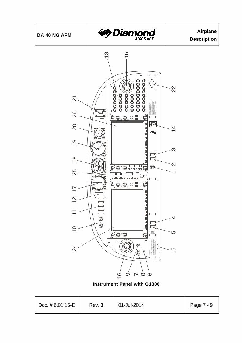
DA 40 NG AFMAirplane
Description
Doc. # 6.01.15-E Rev. 3 01-Jul-2014 Page 7 - 9
Man
ouve
ring
spee
d:
=111
KIA
S (a
bov
e 1
036
up to
120
0 kg
/ ab
ove
2284
up
to 2
646
lb)
=94
KIA
S (7
80 to
103
6 kg
/ 1
720
to 2
284l
b)T
his a
irplan
e m
ay o
nly b
e o
pera
ted
in a
ccor
danc
e w
ith th
e Ai
rpla
ne F
light
Man
ual.
It c
an b
e op
erat
ed in
the
"No
rmal
" and
"Ut
ility
" cat
egor
ies
inno
n-ic
ing
cond
ition
s. P
rovi
ded
that
nat
iona
l ope
ratio
nal r
equi
rem
ents
are
met
and
the
appr
opria
te e
quip
men
t is
inst
alle
d, th
is a
irpla
ne is
ap-
prov
ed fo
r the
follo
win
g kin
ds o
f op
erat
ion:
day
VF
R, n
ight
VFR
and
IFR.
All a
erob
atic
s man
euve
rs in
cludi
ng s
pinn
ing
are
proh
ibite
d. F
orfu
rthe
r ope
ratio
nal
limita
tions
refe
r to
the
Airp
lane
Flig
ht M
anu
al.N
o sm
okin
g
V V
A A
Lim
itatio
ns fo
r G
FC
70
0 A
uto
pilo
t S
yst
em
:D
o n
ot u
se
AP
if “A
ltern
ate
Sta
tic” i
s o
pen.
Co
ndu
ct A
P a
nd
trim
che
ck p
rior
to e
ach
flig
ht (
see
AF
M).
Aut
opilo
t OF
F d
urin
g ta
ke-o
ff a
nd l
and
ing.
Max
imum
spe
ed fo
r au
top
ilot o
pera
tion
is 1
65
KIA
S.
Min
imum
spe
ed f
or a
uto
pilo
t ope
ratio
n is
70
KIAS
.
Min
imum
alti
tude
for
auto
pilo
t ope
ratio
n:C
ruis
e, C
limb,
De
scen
t and
Ma
neu
veri
ng:
800
feet
AG
L
App
roac
h:
200
fee
t AG
L
Ess
Bus
not f
orno
rmal
ope
ratio
nS
ee A
FM
2410
1112
1725
1819
2026
21
13 16
2214
32
14
515
687916
Instrument Panel with G1000
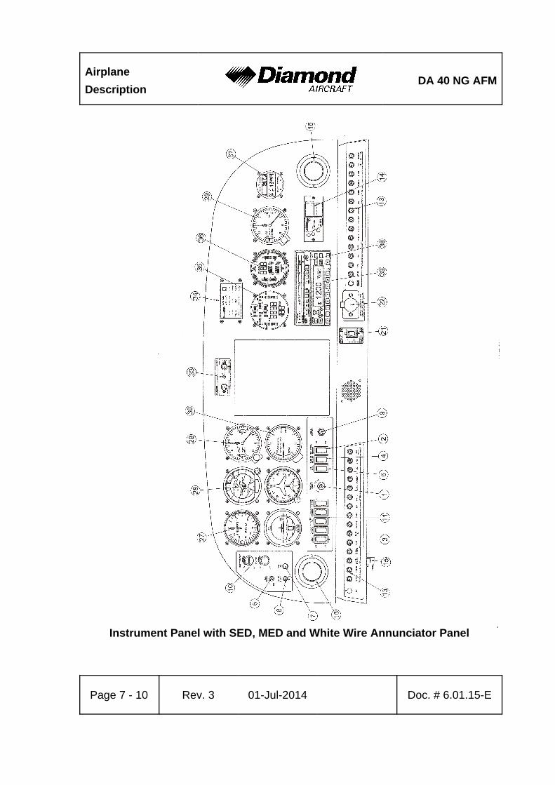
Airplane
DescriptionDA 40 NG AFM
Page 7 - 10 Rev. 3 01-Jul-2014 Doc. # 6.01.15-E
Instrument Panel with SED, MED and White Wire Annunciator Panel
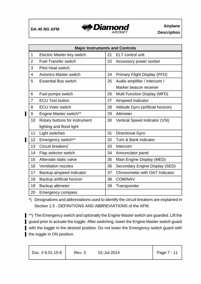
DA 40 NG AFMAirplane
Description
Doc. # 6.01.15-E Rev. 3 01-Jul-2014 Page 7 - 11
Major Instruments and Controls
1 Electric Master key switch 21 ELT control unit
2 Fuel Transfer switch 22 Accessory power socket
3 Pitot Heat switch
4 Avionics Master switch 24 Primary Flight Display (PFD)
5 Essential Bus switch 25 Audio amplifier / Intercom /
Marker beacon receiver
6 Fuel pumps switch 26 Multi Function Display (MFD)
7 ECU Test button 27 Airspeed Indicator
8 ECU Voter switch 28 Attitude Gyro (artificial horizon)
9 Engine Master switch**' 29 Altimeter
10 Rotary buttons for instrument
lighting and flood light
30 Vertical Speed Indicator (VSI)
11 Light switches 31 Directional Gyro
12 Emergency switch**' 32 Turn & Bank indicator
13 Circuit breakers* 33 Intercom
14 Flap selector switch 34 Annunciator panel
15 Alternate static valve 35 Main Engine Display (MED)
16 Ventilation nozzles 36 Secondary Engine Display (SED)
17 Backup airspeed indicator 37 Chronometer with OAT Indicator
18 Backup artificial horizon 38 COM/NAV
19 Backup altimeter 39 Transponder
20 Emergency compass
*) Designations and abbreviations used to identify the circuit breakers are explained in
Section 1.5 - DEFINITIONS AND ABBREVIATIONS of the AFM.
**) The Emergency switch and optionally the Engine Master switch are guarded. Lift the'
guard prior to actuate the toggle. After switching, lower the Engine Master switch guard'
with the toggle in the desired position. Do not lower the Emergency switch guard with'
the toggle in ON position.'
Airplane
DescriptionDA 40 NG AFM
Page 7 - 12 Rev. 3 01-Jul-2014 Doc. # 6.01.15-E
NOTE
The figures on previous pages show the typical DA 40 NG
installation position for the equipment. The actual installation
may vary due to the approved equipment version.
Cockpit Ventilation
Ventilation in the front is provided by the movable ventilation over nozzles (16) in the
instrument panel. Furthermore there are spherical nozzles in the roll bar on the left and
right side next to the front seats as well as on the central console above the passengers’
heads. The spherical nozzles are opened and closed by twisting.
Unconditioned ambient air is supplied to the interior through an inlet on the bottom surface
of the left wing. To increase cabin temperatures when operating at low outside air
temperatures, a ventilation inlet baffle may be installed at the inlet. With the baffle installed,
the rear cabin ventilation nozzles on the left and right hand side and in the central console
above the passengers' heads will be inoperative.
The ventilation inlet baffle consists of a metal plate with rubber edging and is attached
to the bottom LH wing by a camloc.
Heating
Heating is operated using two levers located on the small center console under the
instrument panel.
Right lever: up = heating ON
down = heating OFF
Central lever (air distribution lever):
up = airflow to canopy (DEFROST)
down = airflow to floor (FLOOR)
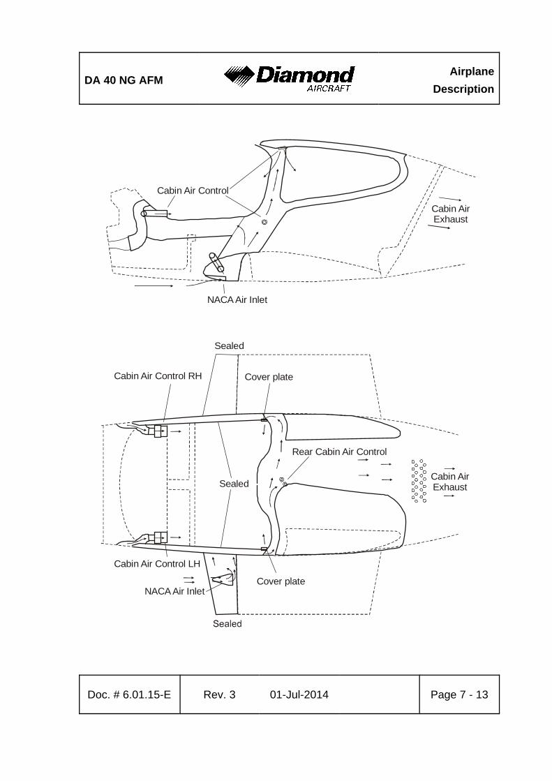
DA 40 NG AFMAirplane
Description
Doc. # 6.01.15-E Rev. 3 01-Jul-2014 Page 7 - 13
NACA Air Inlet
NACA Air Inlet
Cabin Air Control
Cabin Air Control RH
Rear Cabin Air Control
Cabin Air Control LH
Cabin AirExhaust
Cabin AirExhaust
Sealed
Cover plate
Cover plate
Sealed
Airplane
DescriptionDA 40 NG AFM
Page 7 - 14 Rev. 3 01-Jul-2014 Doc. # 6.01.15-E
7.5 LANDING GEAR
The landing gear consists of a main landing gear of spring steel struts, and a free-castering
nose wheel which is spring-loaded by an elastomer package.
The wheel fairings are removable. When flying without wheel fairings, it should be noted
that there is a reduction in some areas of performance (see Chapter 5).
Wheel Brakes
Hydraulically operating disk brakes act on the wheels of the main landing gear. The wheel
brakes are individually operated by means of toe pedals.
Parking Brake
The lever is located on the small center console under the instrument panel, and is in
the upper position when the brakes are released. To operate the parking brake pull the
lever downwards until it catches. Brake pressure is built up by multiple operation of the
toe brake pedals, and is maintained until the parking brake is released. To release, the
lever is pushed upwards.

DA 40 NG AFMAirplane
Description
Doc. # 6.01.15-E Rev. 3 01-Jul-2014 Page 7 - 15
Hydraulic System Schematic'
'
'
'
'
'
'
'
'
'
'
'
'
'
'
'
'
'
'
'
'
'
'
'
'
'
'
'
MasterCylinders
VentedPlug
Pilot’s Pedals
MasterCylinders
Co-Pilot’s Pedals
VentedPlug
Brake FluidReservoir
Fluid Level
LOCK
PARKING BRAKE
RELEASEFlexible Hose
Parking Brake Valve
Brake Disc
Brake Caliper
Pressure Plate
Back Plate
Brake Disc
Pressure Plate
Brake CaliperBack Plate
Flexible Hose
Flexible HoseFlexible Hose
Flexible Hose Flexible Hose
Airplane
DescriptionDA 40 NG AFM
Page 7 - 16 Rev. 3 01-Jul-2014 Doc. # 6.01.15-E
7.6 SEATS AND SAFETY HARNESSES
To increase passive safety, the seats are constructed using a carbon fiber/Kevlar hybrid
material and GFRP. The seats are removable to allow the maintenance and inspection
of the underlying controls. Covers on the control sticks prevent loose objects from falling
into the area of the controls.
The seats have removable furnishings and are equipped with energy-absorbing foam
elements.
The seats are fitted with three-point safety harnesses. The harnesses are fastened by
inserting the belt clip into the belt lock, and are opened by pressing the red release on
the belt lock.
The backs of the rear seats can be laid forward after pulling upwards on the knob of the
locking bolt.
If front seats with adjustable backrests are installed (OÄM 40-252), the angle of the'
backrests can be adjusted for best comfort. The backrest lever is situated on the outboard'
side of the backrest. However, during take-off, landing and emergency landing the'
backrests must be fixed in the upright position designated by a placard on the roll-over'
bar. '
CAUTION'
Before the backrest lever is lifted in order to unlock the'
backrest, lean back towards the backrest to counteract the'
spring load; otherwise the backrest may snap forward.'
'
For adjustment lift the backrest lever and bend forward or backward to the desired backrest'
angle. Then release and press down the backrest lever.'
In case of a defective adjustment mechanism the outboard friction adjustment screw can'
be tightened with a 10 mm hexagon nut in clockwise direction in order to fix the backrest'
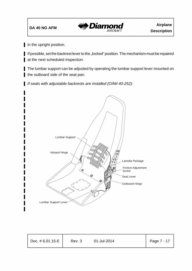
DA 40 NG AFMAirplane
Description
Doc. # 6.01.15-E Rev. 3 01-Jul-2014 Page 7 - 17
Outboard Hinge
Inboard Hinge
Lamella Package
Friction AdjustmentScrew
Seat Lever
Lumbar Support Lever
Lumbar Support
in the upright position.'
If possible, set the backrest lever to the „locked“ position. The mechanism must be repaired'
at the next scheduled inspection. '
The lumbar support can be adjusted by operating the lumbar support lever mounted on'
the outboard side of the seat pan.'
If seats with adjustable backrests are installed (OÄM 40-252):'
'
'
'
'
'
'
'
'
'
'
'
'
'
'
'
'
'
'
'
'
Airplane
DescriptionDA 40 NG AFM
Page 7 - 18 Rev. 3 01-Jul-2014 Doc. # 6.01.15-E
7.7 BAGGAGE COMPARTMENT
The baggage compartment is behind the seat backs of the rear seats. Without a baggage
net, no baggage may be loaded.
As options, a baggage tube or a baggage extension (OÄM 40-164) or a short baggage
extension (OÄM 40-331) may be installed.
NOTE
If OÄM 40-331 is installed, make sure that the baggage does
not block the air vents in the back wall of the short baggage
extension.
7.8 CANOPY, REAR DOOR, AND CABIN INTERIOR
Front Canopy
The front canopy is closed by pulling down on the canopy frame and locking it with the
handle on the left hand side of the canopy frame. On locking, steel bolts catch into mating
holes in polyethylene blocks.
"Cooling gap" position: A second setting allows the bolts to lock in, leaving a gap under
the forward canopy.
The canopy can be key-locked by a locking mechanism on the left side near the canopy
lever by turning the key clockwise. The closed and locked canopy can be opened from
inside by pulling the lever inside the opening handle.
WARNING
The airplane may be operated with the front canopy in the
"cooling gap" position on the ground only. Before take-off the
front canopy must be completely closed and latched, but not
key-locked.

DA 40 NG AFMAirplane
Description
Doc. # 6.01.15-E Rev. 3 01-Jul-2014 Page 7 - 19
Do not key-lock the front canopy before flight to assure
emergency evacuation from outside.
A window on the left and right hand side of the canopy can be opened for additional
ventilation or as emergency window.
Rear Door
The rear door is closed in the same way, by pulling down on the frame and locking it with
the handle. A gas pressure damper prevents the door from dropping; in strong winds the
assembly must be held. The rear door is protected against unintentional opening by an
additional lever.
The door can be locked by a locking mechanism on the left side near the door opening
lever by turning the key clockwise. The closed and locked door can be opened from inside
by pulling the lever inside the opening handle. For a better handling an additional handle
is mounted.
WARNING
Before starting the engine the door must be closed and
latched, but not key-locked.
Do not key-lock the door before flight in order to assure
emergency evacuation from outside.
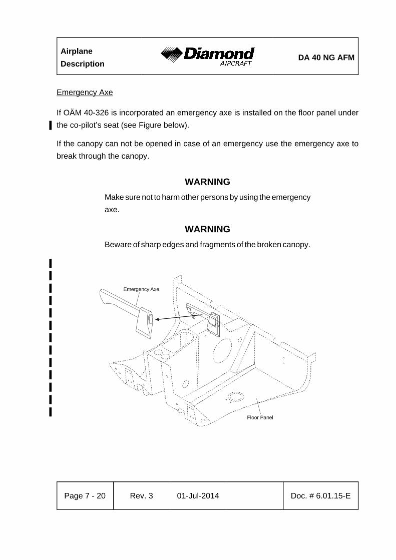
Airplane
DescriptionDA 40 NG AFM
Page 7 - 20 Rev. 3 01-Jul-2014 Doc. # 6.01.15-E
Emergency Axe
If OÄM 40-326 is incorporated an emergency axe is installed on the floor panel under
the co-pilot’s seat (see Figure below).'
If the canopy can not be opened in case of an emergency use the emergency axe to
break through the canopy.
WARNING
Make sure not to harm other persons by using the emergency
axe.
WARNING
Beware of sharp edges and fragments of the broken canopy.
'
'
'
'
'
'
'
'
'
'
'
'
'Floor Panel
Emergency Axe
DA 40 NG AFMAirplane
Description
Doc. # 6.01.15-E Rev. 3 01-Jul-2014 Page 7 - 21
7.9 POWER PLANT
7.9.1 ENGINE, GENERAL
The installed Austro Engine E4-A engine has the following specifications:
- Liquid-cooled four-cylinder four-stroke engine with wet sump lubrication
- Inline construction
- Common rail direct injection
- Propeller speed reducing gear 1:1.69
- Digital engine control with integrated propeller governor (using the gearbox oil
system)
- Turbo charger with intercooler
Displacement:
Max. power: 123.5 kW (165.6 DIN-HP) at 2300 RPM
at sea level and ISA
Max. continuous power: 114.0 kW (152.8 DIN-HP) at 2100 RPM
at sea level and ISA
The indications for monitoring important engine parameters during operation are integrated
within the Garmin G1000 display (if installed) or on the MED and SED (if installed). The
engine can only be operated with the ENGINE MASTER switch ON. The engine has an
EECU (Electrical Engine Control Unit) which receives its electrical power from the
generator when the engine is running. When the engine is not running, the ECU receives
its electrical power from the battery.
Airplane
DescriptionDA 40 NG AFM
Page 7 - 22 Rev. 3 01-Jul-2014 Doc. # 6.01.15-E
7.9.2 OPERATING CONTROLS
POWER lever
The engine performance is controlled by the power lever, situated on the large center
console. 'Front' and 'rear' are defined in relation to the direction of flight.
This lever is used to set the desired engine power LOAD (%)
Lever forward (MAX) = Full power
Lever to rear (IDLE) = Idle
The ECU controls manifold pressure, injected fuel quantity and propeller speed according
to the desired engine power preselected with the power lever.
The propeller governor is attached to the top rear side of the gearbox and uses gearbox
oil for propeller pitch regulation. Following a loss of oil pressure the propeller blades go
to the low pitch stop (maximum RPM), thus allowing continuation of the flight according
to 3.3.6 - DEFECTIVE RPM REGULATING SYSTEM.
DA 40 NG AFMAirplane
Description
Doc. # 6.01.15-E Rev. 3 01-Jul-2014 Page 7 - 23
ELECTRIC MASTER
The key can be switched into three positions:
OFF Disconnecting battery power.
ON Connecting battery power to the power distribution system.
START Starting the engine.
ENGINE MASTER
The engine can only be cranked with the ENGINE MASTER switched to ON. To shut down
the engine the ENGINE MASTER is switched to OFF.
ECU VOTER
For normal operation the switch is set to AUTO. The engine is controlled by either ECU A
or ECU B. In case of a failure of the active electrical engine control unit (ECU) there is
an automatic switch-over to the other ECU. If the automatic switch over fails, switch over
can be done manually by switching to ECU A or ECU B. This procedure should only be
applied in an emergency.
Airplane
DescriptionDA 40 NG AFM
Page 7 - 24 Rev. 3 01-Jul-2014 Doc. # 6.01.15-E
ECU TEST
POWER lever at IDLE:
By pushing and holding the button until the end of the procedure, the self-test of each
engine control unit is started. The procedure is possible on the ground only. Otherwise
the test will not start. During the procedure the ECU performs a switch from ECU A
to ECU B or ECU B to ECU A, whichever is active at the moment, with the propeller
cycling. The propeller RPM is monitored automatically by the ECU. When switching
from one ECU to the other, a slight shake of the engine may occur. Finally the ECU
switches back. After that both caution lights must extinguish and the engine must run
without a change.
Alternate Air
In the event of power loss because of icing or blockage of the air filter, there is the
possibility of drawing air from the engine compartment. The ALTERNATE AIR operating
lever is located under the instrument panel on the left side of the center console. To open
the alternate air source the lever is pulled to the rear. The alternate air source is closed,
with the lever being in the forward position.
Placard on the lever, forward position:
ALTERNATE AIR
Placard on the lever, visible when lever is in the rearward position (alternate air open):
ALTERNATE AIR
ON
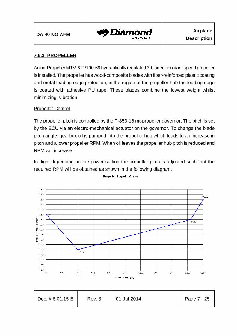
DA 40 NG AFMAirplane
Description
Doc. # 6.01.15-E Rev. 3 01-Jul-2014 Page 7 - 25
7.9.3 PROPELLER
An mt-Propeller MTV-6-R/190-69 hydraulically regulated 3-bladed constant speed propeller
is installed. The propeller has wood-composite blades with fiber-reinforced plastic coating
and metal leading edge protection; in the region of the propeller hub the leading edge
is coated with adhesive PU tape. These blades combine the lowest weight whilst
minimizing vibration.
Propeller Control
The propeller pitch is controlled by the P-853-16 mt-propeller governor. The pitch is set
by the ECU via an electro-mechanical actuator on the governor. To change the blade
pitch angle, gearbox oil is pumped into the propeller hub which leads to an increase in
pitch and a lower propeller RPM. When oil leaves the propeller hub pitch is reduced and
RPM will increase.
In flight depending on the power setting the propeller pitch is adjusted such that the
required RPM will be obtained as shown in the following diagram.
Airplane
DescriptionDA 40 NG AFM
Page 7 - 26 Rev. 3 01-Jul-2014 Doc. # 6.01.15-E
Ground Operation:
CAUTION
Operation on the ground at high RPM should be avoided as
far as possible, as the blades could suffer stone damage. For
this reason a suitable site for engine runs should be selected,
where there are no loose stones or similar items.
WARNING
Never rotate the propeller by hand.
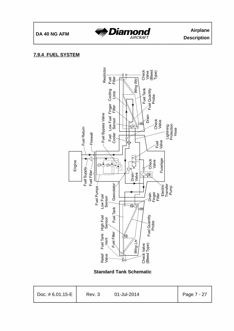
DA 40 NG AFMAirplane
Description
Doc. # 6.01.15-E Rev. 3 01-Jul-2014 Page 7 - 27
7.9.4 FUEL SYSTEM
Standard Tank Schematic
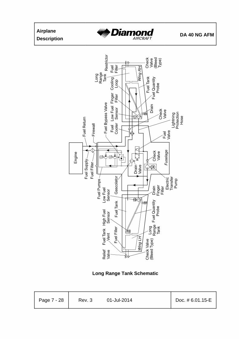
Airplane
DescriptionDA 40 NG AFM
Page 7 - 28 Rev. 3 01-Jul-2014 Doc. # 6.01.15-E
Long Range Tank Schematic
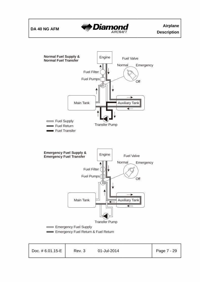
DA 40 NG AFMAirplane
Description
Doc. # 6.01.15-E Rev. 3 01-Jul-2014 Page 7 - 29
Fuel Supply
Fuel ReturnFuel Transfer
Engine
Fuel Filter
Fuel Pumps
Normal
Off
Main Tank Auxiliary Tank
Transfer Pump
Fuel ValveNormal Fuel Supply &Normal Fuel Transfer
Emergency
Emergency Fuel Supply
Emergency Fuel Return & Fuel Return
Engine
Fuel Filter
Fuel Pumps
Normal
Off
Main Tank Auxiliary Tank
Transfer Pump
Fuel ValveEmergency Fuel Supply &Emergency Fuel Transfer
Emergency
Airplane
DescriptionDA 40 NG AFM
Page 7 - 30 Rev. 3 01-Jul-2014 Doc. # 6.01.15-E
Fuel is stored in the fuel tanks which are located in the wings. Normally fuel is taken from
the MAIN tank (left wing).
The fuel is injected with high pressure directly into the combustion chambers. The injection
nozzles (one per cylinder) are supplied with fuel by the common rail. Pressure inside the
rail is generated by a high pressure pump which receives fuel from two independent low
pressure fuel pumps. Both pumps are powered electrically. Depending on the power setting
the rail pressure is controlled by the ECU through an electric valve.
Fuel that is not injected into the combustion chambers is routed through the AUX fuel
tank (right wing) and fed back into the MAIN fuel tank (left wing). This way hot fuel from
the rail is cooled and cold fuel in both tanks is heated.
With the help of an electrical transfer pump fuel can be transferred from the AUX tank
(right wing) to the MAIN tank (left wing) manually.
The transfer pump is switched off automatically when the auxiliary tank is empty or the
main tank is full.
If fuel transfer with the transfer pump becomes impossible for any reason, fuel can also
be taken directly from the AUX tank (right wing) by switching the fuel valve to the
EMERGENCY position. As the return line goes back into the MAIN tank (left wing), fuel
will then be transferred from right to left fuel tank.
As an option additional long range tanks may be installed.
DA 40 NG AFMAirplane
Description
Doc. # 6.01.15-E Rev. 3 01-Jul-2014 Page 7 - 31
CAUTION
Switching the fuel valve to the EMERGENCY position will start
the transferring of fuel with the help of the electrically driven
and engine driven fuel pumps from the auxiliary tank through
the fuel return line to the main tank at a rate of approximately
45 US gal/h (170 liter/h) with FUEL PUMPS switch in OFF
position. The fuel valve must be switched back to the
NORMAL position before the auxiliary tank indication reads
zero. If the fuel valve is not switched back to the NORMAL
position, the engine will stop running as soon as the auxiliary
tank is empty.
Fuel Pumps
The engine is supplied with fuel by two parallel installed independent low pressure
electrically driven fuel pumps. During normal operation one of the two fuel pumps is always
working. In case of a low fuel pressure, the ECU switches automatically to the second
fuel pump. During landing and take-off, or in case of a low fuel pressure both fuel pumps
can be activated with the FUEL PUMPS switch. If both fuel pumps are are set to ON the
fuel pressure increases.
Each fuel pump is electrically connected to an ECU BUS and protected by a 7.5 A circuit
breaker.
NOTE
By switching between ECU A and B the two independent
electrical fuel pumps are switched over as well. In case of an
emergency both pumps can be activated simultaneously by
pushing the FUEL PUMPS switch to the ON position.
Airplane
DescriptionDA 40 NG AFM
Page 7 - 32 Rev. 3 01-Jul-2014 Doc. # 6.01.15-E
Fuel Valve
The fuel valve is located at the center console. The selectable positions are NORMAL,
EMERGENCY and OFF. The desired position is reached by turning the valve handle while
pulling up the safety latch on the valve handle. This is to ensure that a selection is not
made unintentionally.
Standard Fuel Tanks
Main Tank (Left Wing):
The main tank consists of an aluminum chamber and a filler tube which are connected
by a flexible hose. There are two tank vents. One includes a check valve with a capillary
and one includes a pressure relief valve, which operates at 150 mbar (2 PSI) and allows
fuel and air to flow to the outside at higher internal pressure. The relief pressure valve
protects the tank against high pressure if the tank will be overfilled in case of a fuel transfer
failure. The check valve with capillary allows air to enter the tank but prevents flow of
fuel to the outside. The capillary equalizes the air pressure during climb. The hose
terminations are situated on the underside of the wing, approximately 2 meter (7 ft) from
the wing tip.
Auxiliary Tank (Right Wing):
The auxiliary tank consists of an aluminum chamber and a filler tube which are connected
by a flexible hose. There are two tank vents. One includes a check valve with a capillary
and one includes a capillary. The check valve with capillary allows air to enter the tank
during descent but prevents flow of fuel to the outside. The capillary equalizes the air
pressure during climb. The second capillary is installed for additional safety. The hose
terminations are situated on the underside of the wing, approximately 2 meter (7 ft) from
the wing tip.
In each tank a coarse filter (finger filter) is fitted before the outlet. To allow draining of
the tank, an outlet valve (drain valve) is installed at the lowest point of the fuel tank.
DA 40 NG AFMAirplane
Description
Doc. # 6.01.15-E Rev. 3 01-Jul-2014 Page 7 - 33
A gascolator is located at the bottom side of the fuselage which is the lowest point of the
entire fuel system. A drain valve (pull to drain) is mounted to the gascolator, to allow the
remove of water and sediment which has collected in the fuel system.
A capacity probe measures the fuel quantity in each tank. The indication is non-linear,
therefore proportional calculations to determine the remaining fuel quantity or direct
calculations of fuel consumption are not possible. Information about the fuel consumption
can be found in Chapter 5 - PERFORMANCE.
Long Range Tank (if installed)
The tank chamber has a capacity of approx. 5 US gal (19 liter). The ventilation system
of the main and the auxiliary tank remains unchanged.
When the fuel quantity indicator reads zero, only the unusable fuel remains in the tank.
The useable capacity of each tank is 19.5 US gal, the maximum quantity that can be
indicated is 14 US gal. Up to an actual quantity of 14 US gal the indication is correct. At
an actual quantity above 14 US gal the indication remains at 14 US gal.
NOTE
When the fuel quantity indicator reads 14 US gal, the correct
fuel quantity must be determined with the alternate mean for
fuel quantity indication. If this measurement is not carried out,
the fuel quantity available for flight planning is 14 US gal.
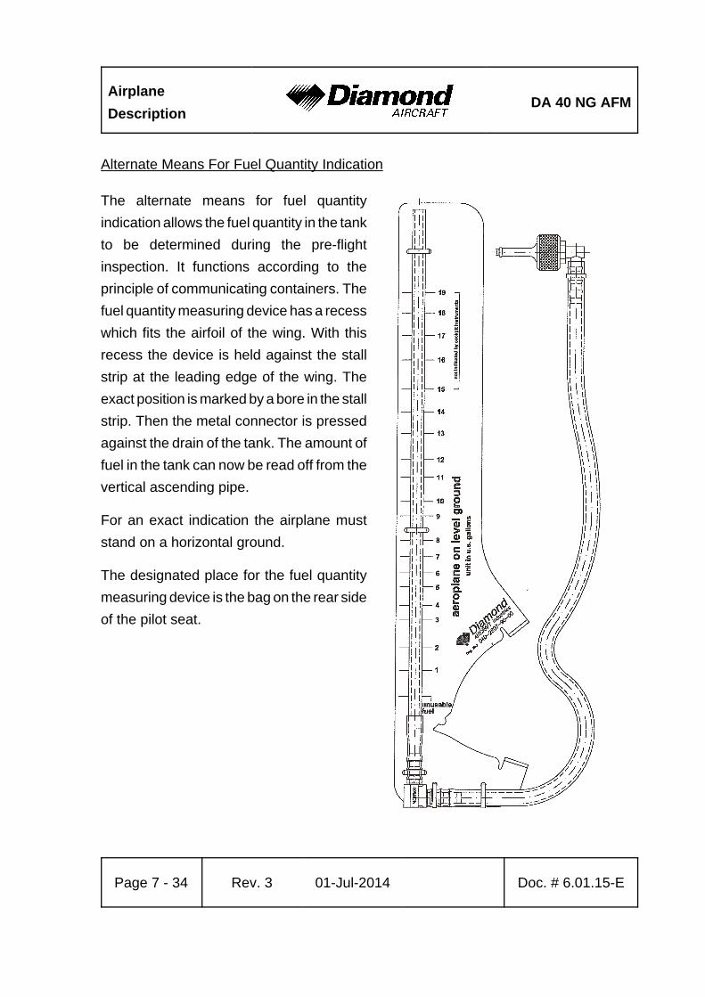
Airplane
DescriptionDA 40 NG AFM
Page 7 - 34 Rev. 3 01-Jul-2014 Doc. # 6.01.15-E
Alternate Means For Fuel Quantity Indication
The alternate means for fuel quantity
indication allows the fuel quantity in the tank
to be determined during the pre-flight
inspection. It functions according to the
principle of communicating containers. The
fuel quantity measuring device has a recess
which fits the airfoil of the wing. With this
recess the device is held against the stall
strip at the leading edge of the wing. The
exact position is marked by a bore in the stall
strip. Then the metal connector is pressed
against the drain of the tank. The amount of
fuel in the tank can now be read off from the
vertical ascending pipe.
For an exact indication the airplane must
stand on a horizontal ground.
The designated place for the fuel quantity
measuring device is the bag on the rear side
of the pilot seat.
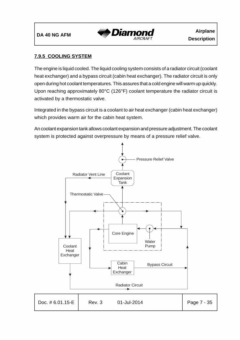
DA 40 NG AFMAirplane
Description
Doc. # 6.01.15-E Rev. 3 01-Jul-2014 Page 7 - 35
Pressure Relief Valve
CoolantExpansion
Tank
Thermostatic Valve
Core Engine
WaterPumpCoolant
HeatExchanger
CabinHeat
Exchanger
Bypass Circuit
Radiator Circuit
Radiator Vent Line
7.9.5 COOLING SYSTEM
The engine is liquid cooled. The liquid cooling system consists of a radiator circuit (coolant
heat exchanger) and a bypass circuit (cabin heat exchanger). The radiator circuit is only
open during hot coolant temperatures. This assures that a cold engine will warm up quickly.
Upon reaching approximately 80°C (126°F) coolant temperature the radiator circuit is
activated by a thermostatic valve.
Integrated in the bypass circuit is a coolant to air heat exchanger (cabin heat exchanger)
which provides warm air for the cabin heat system.
An coolant expansion tank allows coolant expansion and pressure adjustment. The coolant
system is protected against overpressure by means of a pressure relief valve.
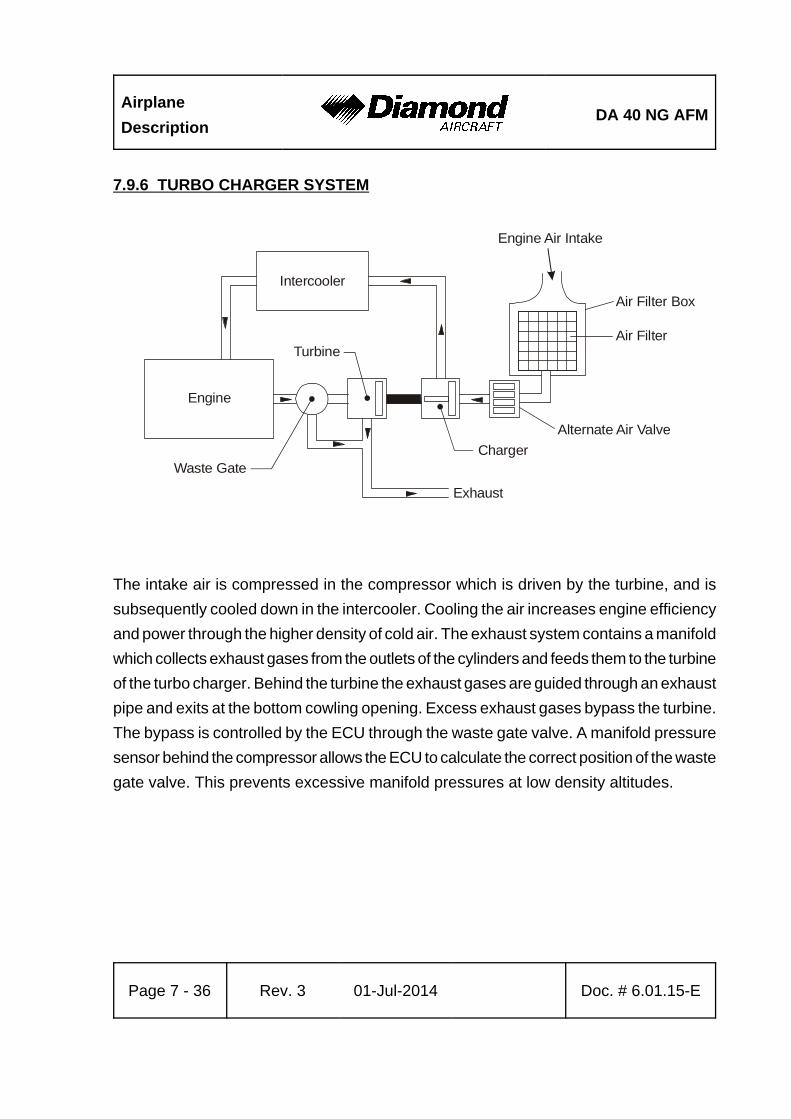
Airplane
DescriptionDA 40 NG AFM
Page 7 - 36 Rev. 3 01-Jul-2014 Doc. # 6.01.15-E
Intercooler
Engine
Waste Gate
Turbine
Charger
Exhaust
Alternate Air Valve
Air Filter
Air Filter Box
Engine Air Intake
7.9.6 TURBO CHARGER SYSTEM
The intake air is compressed in the compressor which is driven by the turbine, and is
subsequently cooled down in the intercooler. Cooling the air increases engine efficiency
and power through the higher density of cold air. The exhaust system contains a manifold
which collects exhaust gases from the outlets of the cylinders and feeds them to the turbine
of the turbo charger. Behind the turbine the exhaust gases are guided through an exhaust
pipe and exits at the bottom cowling opening. Excess exhaust gases bypass the turbine.
The bypass is controlled by the ECU through the waste gate valve. A manifold pressure
sensor behind the compressor allows the ECU to calculate the correct position of the waste
gate valve. This prevents excessive manifold pressures at low density altitudes.
DA 40 NG AFMAirplane
Description
Doc. # 6.01.15-E Rev. 3 01-Jul-2014 Page 7 - 37
7.9.7 OIL SYSTEMS
The engine has two separate oil systems.
Lubrication System (Engine and Turbo Charger)
The engine lubrication is a wet sump lubrication system. Oil is cooled by a separate cooler
on the underside of the engine.
A dip-stick is provided to check the oil quantity through an inspection door on the LH side
of the upper cowling. If required, oil can also be filled in there (for specified oil types refer
to 2.4 - POWER-PLANT LIMITATIONS).
Gearbox and Propeller Governor System
The second oil circuit lubricates the gear and serves the governor system and the
regulation of the propeller.
Gear oil quantity can be checked via an inspection glass which can be reached through
an inspection door on the LH side of the upper cowling.
CAUTION
If the gear oil quantity is too low, an unscheduled
maintenance is necessary (for specified oil types refer to
2.4 - POWER-PLANT LIMITATIONS).
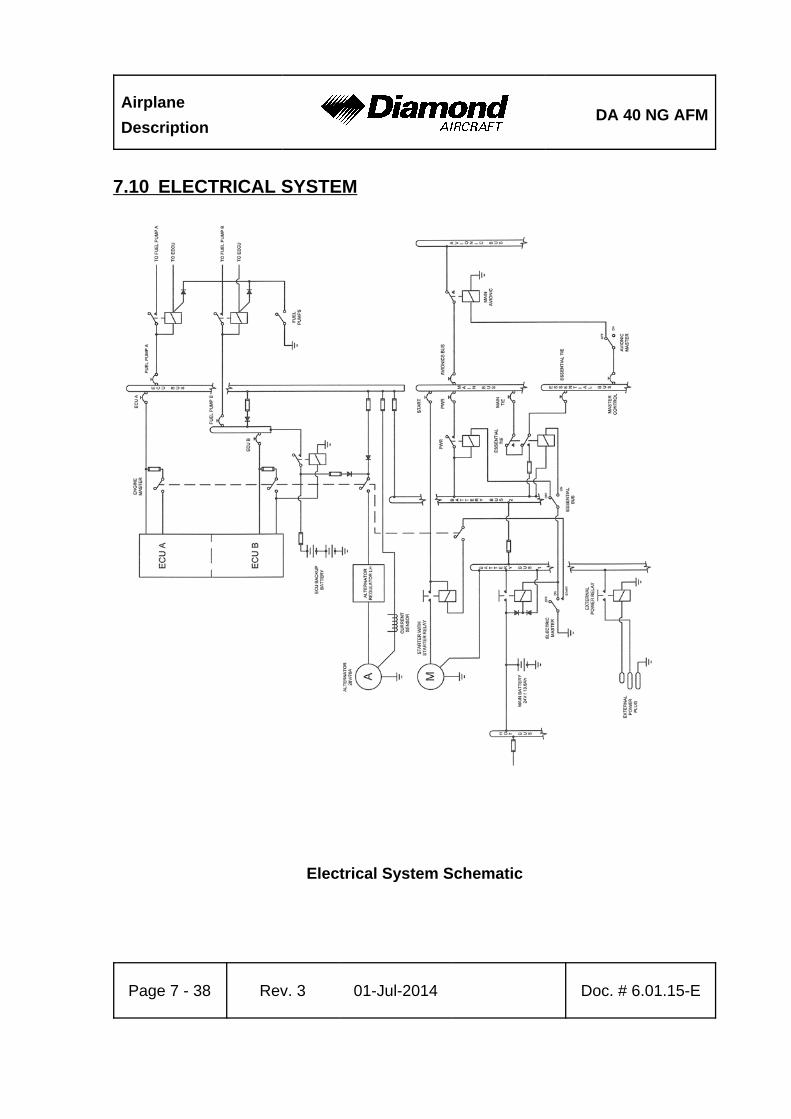
Airplane
DescriptionDA 40 NG AFM
Page 7 - 38 Rev. 3 01-Jul-2014 Doc. # 6.01.15-E
7.10 ELECTRICAL SYSTEM
Electrical System Schematic
DA 40 NG AFMAirplane
Description
Doc. # 6.01.15-E Rev. 3 01-Jul-2014 Page 7 - 39
7.10.1 GENERAL
The DA 40 NG has a 28 Volt DC system, which can be sub-divided into:
- Power generation
- Storage
- Distribution
- Consumers
Power Generation
Power generation is provided by a 70 Ampère alternator (generator) which is mounted
on the bottom left side of the engine. The alternator is driven by a flat-belt.
The power output line of the alternator is connected to the ENG ECU bus via a 100 A
fuse, which is installed in the instrument panel. The power output line also runs through
the current sensor, which provides an indication of the power being supplied to the
electrical system by the alternator including the current for battery charging.
In the event of a main battery failure the field of the alternator is energized by two 12 V,
7.2 Ah sealed-lead-acid batteries (ECU backup batteries) which are installed behind the
first ring frame. The ENGINE MASTER switch connects the ECU backup battery to the
alternator voltage regulator via a 10 A fuse.
Alternator Control:
The alternator control unit includes a comprehensive set of diagnostic functions that will
warn the operator using a warning message (ALTN FAIL on the G1000 system (if installed)
or ALTERNATOR on the White Wire annunciator panel (if installed)) in case of over- or
undervoltage as well as a couple of other internal warning levels.
Airplane
DescriptionDA 40 NG AFM
Page 7 - 40 Rev. 3 01-Jul-2014 Doc. # 6.01.15-E
Storage
Main battery power is stored in a 24 V, 13.6 Ah lead-acid battery mounted behind the
baggage compartment frame. The main battery is connected to the battery bus via the
battery-relay which is installed in the relay junction box behind the baggage compartment
frame.
The battery relay is controlled with the ELECTRIC MASTER key switch which is located
in the center of the instrument panel.
In addition, two 12 V, 7.2 Ah sealed-lead-acid batteries (ECU backup-batteries) are
installed behind the first ring frame as a further source of electrical power for the Engine
Control Unit (ECU B only).
Under normal operating conditions the ECU backup batteries are charged by the ECU
bus. In the event of an alternator failure and a depleted main battery the ECU backup
batteries automatically supply electrical power to ECU B via a 32 A fuse. This prevents
the engine from stopping in the unlikely event of an alternator failure and a totally
discharged main battery.
In addition, a non-rechargeable dry battery is installed in the IFR model as a further source
of power for the attitude gyro (artificial horizon) and the flood light. When the EMERGENCY
switch is set to ON, these two systems are supplied with power for 1 hour, independent
of all other electrical consumers. During each 100 hour inspection, this battery is checked
for proper functioning. Every 2 years or after use (broken seal on the switch) the battery
pack must be replaced.
DA 40 NG AFMAirplane
Description
Doc. # 6.01.15-E Rev. 3 01-Jul-2014 Page 7 - 41
Distribution
Electrical power is distributed via the hot battery bus, the battery bus 1, the battery bus 2,
the ECU-bus, the main bus, the essential bus and the avionic bus.
Hot Battery Bus:
The hot battery bus is directly connected to the main-battery installed in the relay junction
box and cannot be disconnected from the main battery. The hot battery bus provides power
to the accessory power plug and ELT which are protected by their own fuses.
Battery Bus 1:
The battery bus 1 is connected to the main-battery via the battery-relay which can be
controlled by the ELECTRIC MASTER key switch. The battery bus 1 provides power to
the battery bus 2 and heavy duty power to the starter.
The battery bus 1 is also connected to the power input line of the external power plug.
Battery Bus 2:
The battery bus 2 is connected to the battery bus 1 via a 100 A fuse and provides power
to the ECU bus via a 80 A fuse. It also provides power to the main bus via the power relay
which can be controlled by the ELECTRIC MASTER key switch and the ESSENTIAL BUS
switch. The ELECTRIC MASTER key switch must be set to ON and the ESSENTIAL BUS
switch must be set to OFF to connect the battery bus to the main bus.
ECU Bus:
The ECU bus is connected to the battery bus 2 via a 80 A fuse and provides power for
the ECU A and ECU B and their fuel pumps. It is also connected to the power output line
of the alternator via a 100 A fuse. It also provides power for charging the ECU backup-
battery. The ENGINE MASTER switch must be set to ON to activate the ECU A and ECU B
to the ECU bus.
Airplane
DescriptionDA 40 NG AFM
Page 7 - 42 Rev. 3 01-Jul-2014 Doc. # 6.01.15-E
Main Bus:
The main bus is connected to the battery bus via the power-relay. It provides power to
the consumers directly connected to the main bus and the avionic bus via the avionic
master-relay. The AVIONIC MASTER switch must be set to ON to connect the main bus
to the avionic bus. Under normal operating conditions the main bus is also connected
to the essential bus via the essential tie-relay. In the event of an alternator failure the pilot
must switch ON the ESSENTIAL BUS switch (refer to Section 3.4 - FAILURES IN THE
ELECTRICAL SYSTEM). This separates the main bus from the battery bus and the
essential bus and the equipment connected to the main bus no longer has power.
Essential Bus:
Under normal operating conditions the essential bus is connected to the main bus via
the essential tie-relay. The essential bus provides power to the consumers connected
to the essential bus. The AVIONIC MASTER switch must be set to ON to connect the
essential bus to the avionic bus. In the event of an alternator failure the pilot must switch
ON the ESSENTIAL BUS switch (refer to Section 3.4 - FAILURES OF THE ELECTRICAL
SYSTEM). This separates the essential bus from the main bus. The essential bus is then
connected to the battery bus 2 which provides battery power for a limited time to the
equipment essential for safe flight and landing.
Consumers
The individual consumers (e.g. radio, electrical fuel transfer pump, position lights, etc.)
are connected to the appropriate bus via automatic circuit breakers.
Designations and abbreviations used to identify the circuit breakers are explained in
Section 1.5 - DEFINITIONS AND ABBREVIATIONS.
DA 40 NG AFMAirplane
Description
Doc. # 6.01.15-E Rev. 3 01-Jul-2014 Page 7 - 43
Voltmeter
The voltmeter shows the voltage of the essential bus. Under normal operating conditions
the alternator voltage is shown, otherwise it is the voltage of the main battery.
Ammeter
The ammeter displays the intensity of current which is supplied to the electrical system
by the alternator, including the current for battery charging.
Landing and Taxi Lights
Landing and taxi lights are built into the left wing, and are each operated by means of
a switch (LANDING, TAXI) on the row of switches on the instrument panel.
Position and Strobe Lights
Combined position and strobe lights (anti collision lights) are installed on both wing tips.
Each system is operated by a switch (POSITION, STROBE) on the row of switches on
the instrument panel.
Flood Light
A two-dimensional light emitter is mounted above the instrument panel. It illuminates the
instrument panel as well as all levers, switches, etc. With a rotary button (FLOOD) in the
left-hand section of the instrument panel the flood light is switched on and its brightness
is adjusted.
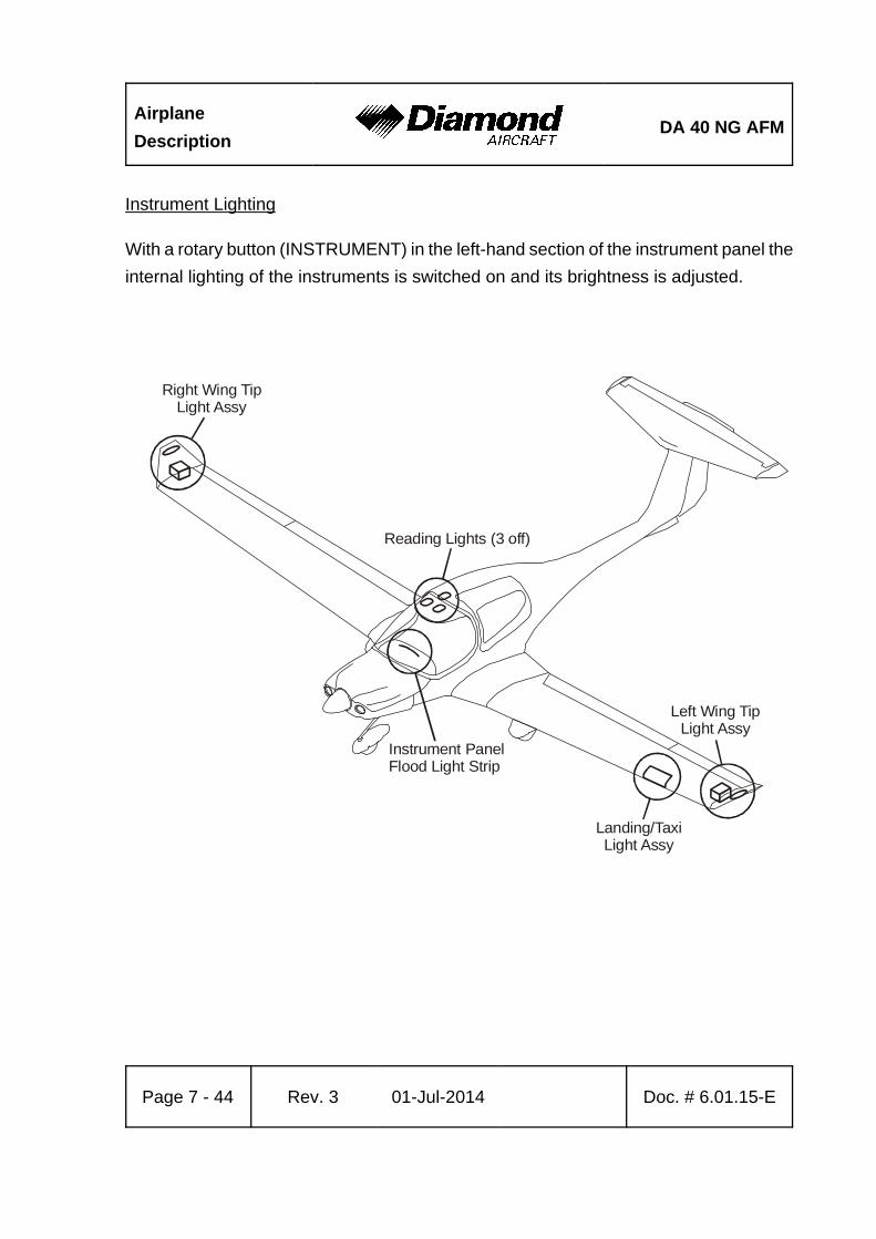
Airplane
DescriptionDA 40 NG AFM
Page 7 - 44 Rev. 3 01-Jul-2014 Doc. # 6.01.15-E
Right Wing TipLight Assy
Reading Lights (3 off)
Instrument PanelFlood Light Strip
Left Wing TipLight Assy
Landing/TaxiLight Assy
Instrument Lighting
With a rotary button (INSTRUMENT) in the left-hand section of the instrument panel the
internal lighting of the instruments is switched on and its brightness is adjusted.
DA 40 NG AFMAirplane
Description
Doc. # 6.01.15-E Rev. 3 01-Jul-2014 Page 7 - 45
Pitot Heating
The Pitot probe, which provides measurement for the Pitot-static system, is electrically
heated. The heating is activated with a switch (PITOT) on the row of switches on the
instrument panel. The temperature is automatically kept constant by means of a thermal
switch on the Pitot probe, and as an additional safety measure a thermal fuse is built in.
If this thermal fuse is activated, the Pitot heating can no longer be switched on. PITOT FAIL
on the G1000 (if installed) or PITOT on the White Wire annunciator panel (if installed)
will be displayed, if the thermal fuse or the thermal switch is activated and the PITOT HT
is set to ON. The PITOT HT OFF indication on the G1000 (if installed) is on if the Pitot
heating is switched off.
Airplane
DescriptionDA 40 NG AFM
Page 7 - 46 Rev. 3 01-Jul-2014 Doc. # 6.01.15-E
7.10.2 ENGINE CONTROL UNIT / ECU
Engine Control and Regulation
The Electrical ECU is used to control the engine actuator (e.g. fuel injector) according
to the engine sensor information. The ECU monitors, controls and regulates all important
parameters for engine operation.
Sensors installed are:
- Oil temperature (lubrication system engine) / OIL TEMP (G1000, if installed),
OT (MED, if installed)
- Oil pressure (lubrication system engine) / OIL PRES (G1000, if installed),
OP (MED, if installed)
- Coolant temperature / COOLANT TEMP (G1000, if installed),
CT (MED, if installed)
- Gearbox temperature / GEARBOX (G1000, if installed),
GT (MED, if installed)
- Camshaft RPM (twice)
- Crankshaft RPM (twice)
- Fuel pressure in the common rail
- Manifold pressure
- Manifold air temperature
- Ambient air pressure
- Propeller governor / oil pressure
- POWER lever position (twice)
- Voltage
- Starter switch signal
- Fuel pressure
- VOTER switch signal
- ECU TEST switch signal
DA 40 NG AFMAirplane
Description
Doc. # 6.01.15-E Rev. 3 01-Jul-2014 Page 7 - 47
In accordance with the received signals and a comparison with the programmed
characteristic diagrams the necessary inputs are calculated and transmitted by the
following signal lines to the engine:
- Signal for propeller governor pressure valve
- Signal for the rail-pressure regulation valve
- Signal for each of the 4 injection nozzles
- Activation of the glow plugs
- Signal for the waste gate valve
The following alerts are displayed on the PFD of the G1000 (if installed) or White Wire
annunciator panel (if installed):
- Glow sparks active
- Status ECU A
- Status ECU B
- Low fuel pressure warning (on the G1000, if installed)
The Electrical ECU consists of two similar ECUs. A VOTER switch is integrated in the
Electrical ECU and proposes an ECU to control the engine regarding the ECU operating
hours or in case of a failure the ECU with better engine control capability.
A fault in one of the ECUs is indicated by a caution message (ECU A/B FAIL on the PFD
(if G1000 is installed) or ECU A/B on the White Wire annunciator panel (if installed)). After
the indication of the ECU A/B FAIL or ECU A/B caution message, the engine must be
serviced.

Airplane
DescriptionDA 40 NG AFM
Page 7 - 48 Rev. 3 01-Jul-2014 Doc. # 6.01.15-E
7.11 PITOT-STATIC SYSTEM
Total pressure is measured at the leading edge of a Pitot probe under the left wing. Static
pressure is measured through the static ports in the rear fuselage. To protect against dirt
and condensation there are filters in the system. The Pitot probe is electrically heated.
With the alternate static valve, the static pressure in the cabin can be used as static
pressure source in the event of a failure of the static system.
7.12 STALL WARNING SYSTEM
If airspeed drops, suction on the orifice at the leading edge of the left wing will increase
until the stall warning horn, located in the instrument panel, will sound. The horn becomes
progressively louder the closer one gets to stalling speed. Suction at an orifice on the
left wing leading edge activates the horn via a hose. The orifice for the stall warning in
the left wing is marked by a red ring.
DA 40 NG AFM Handling
Doc. # 6.01.15-E Rev. 3 01-Jul-2014 Page 8 - 1
CHAPTER 8
AIRPLANE HANDLING, CARE AND MAINTENANCE
Page
8.1 INTRODUCTION . . . . . . . . . . . . . . . . . . . . . . . . . . . . . . . . . . . . . . . 8-2
8.2 AIRPLANE INSPECTION INTERVALS . . . . . . . . . . . . . . . . . . . . . . 8-2
8.3 AIRPLANE ALTERATIONS OR REPAIRS . . . . . . . . . . . . . . . . . . . 8-3
8.4 GROUND HANDLING / ROAD TRANSPORT . . . . . . . . . . . . . . . . . 8-3
8.4.1 GROUND HANDLING WITHOUT TOW BAR . . . . . . . . . . . . 8-3
8.4.2 GROUND HANDLING WITH TOW BAR . . . . . . . . . . . . . . . . 8-4
8.4.3 PARKING . . . . . . . . . . . . . . . . . . . . . . . . . . . . . . . . . . . . . . . 8-6
8.4.4 MOORING . . . . . . . . . . . . . . . . . . . . . . . . . . . . . . . . . . . . . . . 8-9
8.4.5 JACKING . . . . . . . . . . . . . . . . . . . . . . . . . . . . . . . . . . . . . . . . 8-9
8.4.6 ALIGNMENT . . . . . . . . . . . . . . . . . . . . . . . . . . . . . . . . . . . . . 8-9
8.4.7 ROAD TRANSPORT . . . . . . . . . . . . . . . . . . . . . . . . . . . . . . 8-10
8.5 CLEANING AND CARE . . . . . . . . . . . . . . . . . . . . . . . . . . . . . . . . 8-11
8.5.1 PAINTED SURFACES . . . . . . . . . . . . . . . . . . . . . . . . . . . . 8-11
8.5.2 CANOPY AND REAR DOOR . . . . . . . . . . . . . . . . . . . . . . . 8-11
8.5.3 PROPELLER . . . . . . . . . . . . . . . . . . . . . . . . . . . . . . . . . . . . 8-12
8.5.4 ENGINE . . . . . . . . . . . . . . . . . . . . . . . . . . . . . . . . . . . . . . . 8-12
8.5.5 INTERIOR SURFACES . . . . . . . . . . . . . . . . . . . . . . . . . . . . 8-12
8.6 GROUND DE-ICING . . . . . . . . . . . . . . . . . . . . . . . . . . . . . . . . . . . 8-13

Handling DA 40 NG AFM
Page 8 - 2 Rev. 3 01-Jul-2014 Doc. # 6.01.15-E
8.1 INTRODUCTION
Chapter 8 contains the manufacturer's recommended procedures for proper ground
handling and servicing of the airplane. The Airplane Maintenance Manual
(Doc. No. 6.02.15) lists certain inspection and maintenance requirements which must
be followed if the airplane is to retain a new plane performance and reliability.
8.2 AIRPLANE INSPECTION INTERVALS
Inspections are scheduled every 100, 200 and 1000 hours. Independent of the flight hours
an annual inspection must be performed every year. The respective inspection checklists
are prescribed in the Airplane Maintenance Manual, Chapter 05.
For maintenance work on engine and propeller, the currently effective Operator's Manuals,
Service Instructions, Service Letters and Service Bulletins of Austro Engine and
mt-propeller must be followed. For airframe inspections, the currently effective
checklists/manuals, Service Bulletins and Service Instructions of the manufacturer must
be followed.
CAUTION
Unscheduled maintenance checks are required after:
- Hard landings
- Propeller strike
- Engine fire
- Lightning strike
- Occurrence of other malfunctions and damage
Unscheduled maintenance checks are described in the
Airplane Maintenance Manual (Doc. No. 6.02.15;
Section 05-50).
DA 40 NG AFM Handling
Doc. # 6.01.15-E Rev. 3 01-Jul-2014 Page 8 - 3
8.3 AIRPLANE ALTERATIONS OR REPAIRS
Alterations or repairs of the airplane may be carried out only according to the Airplane
Maintenance Manual, Doc. No. 6.02.15, and only by authorized personnel.
8.4 GROUND HANDLING / ROAD TRANSPORT
8.4.1 GROUND HANDLING WITHOUT TOW BAR
During forward traversing the nose wheel will follow the movement of the airplane. Change
in direction is achieved by pulling on the propeller near the spinner. To traverse in the
rear direction, the tail section of the airplane should be pushed down until the nose wheel
is clear of the ground. This method can also be used to turn the airplane around its main
landing gear.

Handling DA 40 NG AFM
Page 8 - 4 Rev. 3 01-Jul-2014 Doc. # 6.01.15-E
8.4.2 GROUND HANDLING WITH TOW BAR
For pushing or pulling the airplane on the ground, it is recommended to use the tow bar
which is available from the manufacturer. The tow bar is bent apart and engaged in the
appropriate holes in the nose wheel fairing as shown on the picture below. The arresting
knob must be fully engaged.
DA 40 NG AFM Handling
Doc. # 6.01.15-E Rev. 3 01-Jul-2014 Page 8 - 5
WARNING
The tow bar must be removed before starting the engine.
CAUTION
The tow bar may only be used for moving the airplane on the
ground by hand. After moving the airplane, the tow bar must
be removed.
NOTE
When moving the airplane rearward, the tow bar must be held
firmly to prevent abrupt sideward deflection of the nose wheel.
Handling DA 40 NG AFM
Page 8 - 6 Rev. 3 01-Jul-2014 Doc. # 6.01.15-E
8.4.3 PARKING
For short term parking, the airplane must be positioned into the wind, the parking brake
must be engaged and the wing flaps must be in the retracted position. For extended and
unattended parking, as well as in unpredictable wind conditions, the airplane must be
anchored to the ground or placed in a hangar. Parking in a hangar is recommended.
For outdoor parking at temperatures below -38°C (-36.4°F) make sure that the distilled%
water / coolant mixture ratio is 40 % to 60 %.%
If the battery heating system (OÄM 40-363) is installed, it is recommended to use the%
system when the airplane is parked at outside air temperature below 0°C (32°F).%
Control Surfaces Gust Lock
The manufacturer offers a control surfaces gust lock which can be used to block the
primary controls. It is recommended that the control surfaces gust lock be used when
parking outdoors, because otherwise the control surfaces can hit the stops in strong tail
wind. This can lead to excessive wear or damage.
WARNING
The control surfaces gust lock must be removed before flight.
DA 40 NG AFM Handling
Doc. # 6.01.15-E Rev. 3 01-Jul-2014 Page 8 - 7
The control surfaces gust lock is installed as follows:
1. Move the rudder pedals fully rearward.
2. Engage the control surfaces gust lock with the pedals.
3. Engage the stick, wrap straps around stick once.
4. Attach the locks and tighten the straps.
For removal, reverse the sequence.
NOTE
It is recommended to cover the canopy when the airplane is
parked outdoors, in direct sunlight, at outside air temperatures
above +25 °C (77 °F), in order to prevent excessive heat
generation within the instrument panel which can cause
damage to the equipment. Such a canopy cover is available
from Diamond Aircraft Industries, P/N: S_30172.
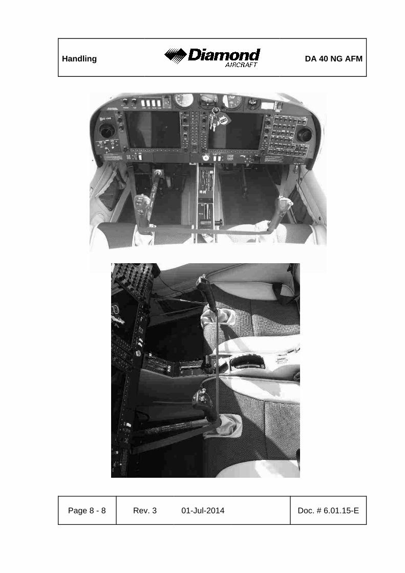
Handling DA 40 NG AFM
Page 8 - 8 Rev. 3 01-Jul-2014 Doc. # 6.01.15-E
DA 40 NG AFM Handling
Doc. # 6.01.15-E Rev. 3 01-Jul-2014 Page 8 - 9
8.4.4 MOORING
The tail fin of the airplane has a hole which can be used to tie-down the airplane to the
ground. Also on each wing near the wing tip, an eyelet with a metric M8 thread can be
installed and used as tie-down points.
8.4.5 JACKING
The airplane can be jacked at the two jackpoints located on the lower side of the fuselage*s
LH and RH root ribs as well as at the tail fin.
8.4.6 ALIGNMENT
For alignment push down on the tail section at the fuselage/vertical tail junction until the
nose wheel is clear of the ground. With the nose wheel free, the airplane can be turned
around the main landing gear. After turning the airplane into the correct position, release
the tail section slowly until the nose wheel is back on the ground.
Handling DA 40 NG AFM
Page 8 - 10 Rev. 3 01-Jul-2014 Doc. # 6.01.15-E
8.4.7 ROAD TRANSPORT
For transporting the airplane on the road it is recommended that an open trailer be used.
All airplane components must be stored on a cushioned surface and secured to avoid
any movement during transportation.
NOTE
Disassembling and Assembling of the airplane is a
maintenance action and requires qualified personel.
1. Fuselage:
The fuselage should stand on the main and nose landing gear. It must be ensured that
the fuselage will not move in any direction. Furthermore, it must be ensured that the
propeller has sufficient clearance so that it cannot be damaged due to fuselage movement
during transportation.
2. Wings:
For transportation, both wings must be removed from the fuselage. To avoid any damage,
the wings must be stored in an upright position on the leading edge with the root rib area
positioned on an upholstered profiled surface with a width of at least 400 mm (1.3 ft). The
outside wing area (approximately 3 m (10 ft) from the root rib area) must be placed on
an upholstered profiled surface with a minimum width of 300 mm (1 ft).
The wings must be secured to avoid any sliding movement to the rear.
3. Horizontal Stabilizer:
The horizontal stabilizer must be stored flat on the trailer and secured with straps, or in
an upright position sitting on the leading edge on a profiled surface. All storing surfaces
must be upholstered with felt or cellular rubber.
DA 40 NG AFM Handling
Doc. # 6.01.15-E Rev. 3 01-Jul-2014 Page 8 - 11
8.5 CLEANING AND CARE
CAUTION
The airplane must be kept clean. The bright surface prevents
the structure from overheating.
CAUTION
Excessive dirt deteriorates the flight performance.
8.5.1 PAINTED SURFACES
The entire surface of the airplane is painted with a white weatherproof two component
paint. Nevertheless, it is recommended to protect the airplane against moisture and
dampness. It is also recommended not to store the airplane outside for long periods of
time.
Dirt, insects, etc. can be removed with water alone and if necessary with a mild detergent.
An automotive paint cleaner can be used for stubborn spots. For best results, clean the
airplane after the day's flying is ended, so that the dirt will not become ingrained.
Oil stains, exhaust stains, etc. on the lower fuselage skin can be removed with a cold
detergent. Before starting, ensure that the detergent does not affect the surface finish.
Use commercial automotive preservatives without silicone additives to conserve the paint
finish.
8.5.2 CANOPY AND REAR DOOR
The canopy and rear door should be cleaned with 'Plexiklar' or any other acrylic glass
detergent if available; otherwise use lukewarm water. Final cleaning should be done with
a clean piece of chamois-leather or soft cloth. Never rub or polish dry acrylic glass.
Handling DA 40 NG AFM
Page 8 - 12 Rev. 3 01-Jul-2014 Doc. # 6.01.15-E
8.5.3 PROPELLER
Damage and malfunctions during operation must be inspected by authorized personnel.
Surface
The manufacturer uses PU paint or acrylic paint which is resistant to almost any solvent.
The blades may be treated with commercial automotive cleaning agents or preservatives.
The penetration of moisture into the wooden core must be avoided by all means. Should
doubts arise, an appropriately rated inspector must be consulted.
8.5.4 ENGINE
Engine cleaning is part of the scheduled inspections.
8.5.5 INTERIOR SURFACES
The interior should be cleaned using a vacuum cleaner. All loose items (pens, bags etc.)
should be removed or properly stored and secured.
All instruments can be cleaned using a soft dry cloth, plastic surfaces should be wiped
clean using a damp cloth without any cleaning agents.
CAUTION
The PFD and MFD displays use a lens coated with a special
anti-reflective coating that is very sensitive to skin oils, waxes,
and abrasive cleaners. CLEANERS CONTAINING AMMONIA
WILL HARM THE ANTI-REFLECTIVE COATING. It is very
important to clean the lens using a clean, lint-free cloth and
an eyeglass lens cleaner that is specified as safe for
anti-reflective coatings.

DA 40 NG AFM Handling
Doc. # 6.01.15-E Rev. 3 01-Jul-2014 Page 8 - 13
8.6 GROUND DE-ICING
Approved de-icing fluids are:
Manufacturer Name
„Kilfrost“ TKS 80
„Aeroshell“ Compound 07
Any source AL-5 (DTD 406B)
1. Remove any snow from the airplane using a soft brush.
2. Spray de-icing fluid onto ice-covered surfaces using a suitable spray bottle.
3. Use a soft piece of cloth to wipe the airplane dry.

Handling DA 40 NG AFM
Page 8 - 14 Rev. 3 01-Jul-2014 Doc. # 6.01.15-E
Intentionally left blank
DA 40 NG AFM Supplements
Doc. # 6.01.15-E Rev. 3 01-Jul-2014 Page 9 - 1
CHAPTER 9
SUPPLEMENTS
Page
9.1 INTRODUCTION . . . . . . . . . . . . . . . . . . . . . . . . . . . . . . . . . . . . . . . 9-2
9.2 LIST OF SUPPLEMENTS . . . . . . . . . . . . . . . . . . . . . . . . . . . . . . . . 9-3
Supplements DA 40 NG AFM
Page 9 - 2 Rev. 3 01-Jul-2014 Doc. # 6.01.15-E
9.1 INTRODUCTION
Chapter 9 contains information concerning additional (optional) equipment of the
DA 40 NG.
Unless otherwise stated, the procedures given in the Supplements must be applied in
addition to the procedures given in the main part of the Airplane Flight Manual.
All approved supplements are listed in the List of Supplements in this Chapter.
The Airplane Flight Manual contains exactly those Supplements which correspond to the
installed equipment according to the Equipment Inventory of Section 6.5.
NOTE
The listed Supplements cannot be installed in any arbitrary
combination.

DA 40 NG AFM Supplements
Doc. # 6.01.15-E Rev. 3 01-Jul-2014 Page 9 - 3
9.2 LIST OF SUPPLEMENTS
Airplane S/N: Registration: Date:
Sup.No.
TitleRev.No.
Dateapplicable
YES NO
A01 Garmin G1000 Avionics System 1% 01 Jul 2014% 9 9
A02 Intercom PM 1000 II 0 15 Mar 2011 9 9
A05
Conventional Cockpit DA 40 NG
Club (SED, MED, White Wire
Annunciator Panel)
0 15 Mar 2011 9 9
A13Autopilot System KAP 140
Bendix/King1 15 Mar 2011 9 9
A29 Garmin Transponder GTX 328 0 15 Mar 2011 9 9
A30 Garmin COM/NAV SL 30 0 15 Mar 2011 9 9
A33%
Integrated Avionics System%
Garmin 1000, SBAS and P-RNAV%
Operation%
2% 01 Jul 2014% 9% 9%
E07% Winter Baffle Fresh Air Inlet% 1% 01 Jul 2014% 9% 9%
S04 ELT ME 406 0 01 Apr 2010 9 9
S06G1000 Synthetic Vision
Technology1% 15 Mar 2011% 9 9
S07% Recirculating Cabin - Air Cooling% 5% 01 Jul 2014% 9% 9%
O01%Use of the DA 40 NG as Tow-%
Plane%1% 01 Jul 2014% 9% 9%
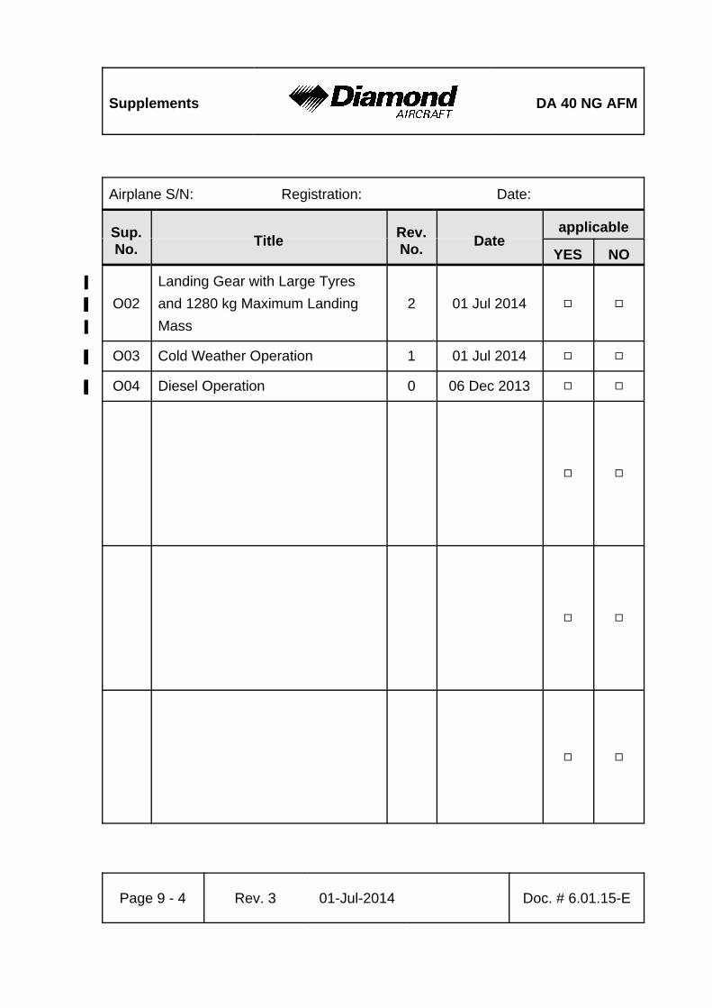
Supplements DA 40 NG AFM
Airplane S/N: Registration: Date:
Sup.No.
TitleRev.No.
Dateapplicable
YES NO
Page 9 - 4 Rev. 3 01-Jul-2014 Doc. # 6.01.15-E
O02%
Landing Gear with Large Tyres%
and 1280 kg Maximum Landing%
Mass%
2% 01 Jul 2014% 9% 9%
O03% Cold Weather Operation% 1% 01 Jul 2014% 9% 9%
O04% Diesel Operation% 0% 06 Dec 2013% 9% 9%
9 9
9 9
9 9