Embed Size (px)
DESCRIPTION
ss
Citation preview

Designation: D 6079 – 99 An American National Standard
Standard Test Method forEvaluating Lubricity of Diesel Fuels by the High-FrequencyReciprocating Rig (HFRR) 1
This standard is issued under the fixed designation D 6079; the number immediately following the designation indicates the year oforiginal adoption or, in the case of revision, the year of last revision. A number in parentheses indicates the year of last reapproval. Asuperscript epsilon (e) indicates an editorial change since the last revision or reapproval.
1. Scope
1.1 This test method evaluates the lubricity of diesel fuelsusing a high-frequency reciprocating rig (HFRR).
1.2 This test method is applicable to middle distillate fuels,such as Grades Low Sulfur No. 1 D, Low Sulfur No. 2 D, No.1 D, and No. 2 D diesel fuels, in accordance with SpecificationD 975; and other similar petroleum-based fuels which can beused in diesel engines
NOTE 1—It is not known that this test method will predict theperformance of all additive/fuel combinations. Additional work is under-way to further establish this correlation and future revisions of this testmethod may be necessary once this work is complete.
1.3 The values stated in SI units are to be regarded as thestandard.
1.4 This standard does not purport to address all of thesafety concerns, if any, associated with its use. It is theresponsibility of the user of this standard to establish appro-priate safety and health practices and determine the applicableregulatory limitations prior to use.Specific hazard statementsare given in section 7.
2. Referenced Documents
2.1 ASTM Standards:D 329 Specification for Acetone2
D 362 Specification for Industrial Grade Toluene3
D 975 Specification for Diesel Fuel Oils4
D 4057 Practice for Manual Sampling of Petroleum andPetroleum Products5
D 4177 Practice for Automatic Sampling of Petroleum andPetroleum Products5
D 4306 Practice for Aviation Fuel Sample Containers forTests Affected by Trace Contamination5
D 5290 Test Method for Measurement of Oil Consumption,
Piston Deposits, and Wear in a Heavy-Duty High-SpeedDiesel Engine—NTC-400 Procedure6
D 6078 Test Method for Evaluating Lubricity of DieselFuels by the Scuffing Load Ball-On-Cylinder LubricityEvaluator (SLBOCLE)7
E 18 Test Method for Rockwell Hardness and RockwellSuperficial Hardness of Metallic Materials8
E 92 Test Method for Vickers Hardness of Metallic Mate-rials 8
2.2 American Iron and Steel Institute Standard:9
AISI E-52100 Chromium Alloy Steel2.3 American National Standards Institute Standard:10
ANSI B3.12 Metal Balls
3. Terminology
3.1 Definitions of Terms Specific to This Standard:3.1.1 lubricity, n—a qualitative term describing the ability
of a fluid to affect friction between, and wear to, surfaces inrelative motion under load.
3.1.1.1 Discussion—In this test method, the lubricity of afluid is evaluated by the wear scar, in millimetres, produced onan oscillating ball from contact with a stationary disc immersedin the fluid operating under defined and controlled conditions.
3.1.2 boundary lubrication, n—a condition in which thefriction and wear between two surfaces in relative motion aredetermined by the properties of the surfaces and the propertiesof the contacting fluid, other than bulk viscosity.
3.1.2.1 Discussion—Metal to metal contact occurs and thechemistry of the system is involved. Physically adsorbed orchemically reacted soft films (usually very thin) supportcontact loads. As a result, some wear is inevitable.
4. Summary of Test Method
4.1 A 2-mL test specimen of fuel is placed in the testreservoir of an HFRR and adjusted to either of the standard
1 This test method is under the jurisdiction of ASTM Committee D-2 onPetroleum Products and Lubricants and is the direct responsibility of SubcommitteeD02.E2 on Diesel Fuels. This test method was developed by ISO/TC22/SC7/WG6and is a part of ISO 12156.
Current edition approved Nov. 10, 1999. Published December 1999.2 Annual Book of ASTM Standards, Vol 06.04.3 Discontinued—See 1998Annual Book of ASTM Standards, Vol 06.03.4 Annual Book of ASTM Standards, Vol 05.01.5 Annual Book of ASTM Standards, Vol 05.02.
6 Discontinued–See 1997Annual Book of ASTM Standards, Vol 05.03.7 Annual Book of ASTM Standards, Vol 05.04.8 Annual Book of ASTM Standards, Vol 03.01.9 Available from American Iron and Steel Institute, 1000 16th St., NW, Wash-
ington, DC 20036.10 Available from American National Standards Institute, 11 W. 42nd St., NW,
Washington, DC 20036.
1
Copyright © ASTM, 100 Barr Harbor Drive, West Conshohocken, PA 19428-2959, United States.
temperatures (25 or 60°C). The preferred test temperature is60°C, except where there may be concerns about loss of fuelbecause of its volatility or degradation of the fuel because ofthe temperature.
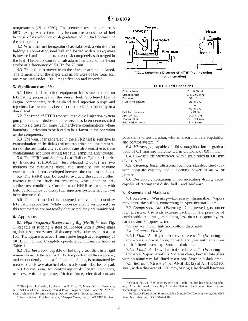
4.2 When the fuel temperature has stabilized, a vibrator armholding a nonrotating steel ball and loaded with a 200-g massis lowered until it contacts a test disk completely submerged inthe fuel. The ball is caused to rub against the disk with a 1-mmstroke at a frequency of 50 Hz for 75 min.
4.3 The ball is removed from the vibrator arm and cleaned.The dimensions of the major and minor axes of the wear scarare measured under 1003 magnification and recorded.
5. Significance and Use
5.1 Diesel fuel injection equipment has some reliance onlubricating properties of the diesel fuel. Shortened life ofengine components, such as diesel fuel injection pumps andinjectors, has sometimes been ascribed to lack of lubricity in adiesel fuel.
5.2 The trend of HFRR test results to diesel injection systempump component distress due to wear has been demonstratedin pump rig tests for some fuel/hardware combinations whereboundary lubrication is believed to be a factor in the operationof the component.11
5.3 The wear scar generated in the HFRR test is sensitive tocontamination of the fluids and test materials and the tempera-ture of the test. Lubricity evaluations are also sensitive to tracecontaminants acquired during test fuel sampling and storage.
5.4 The HFRR and Scuffing Load Ball on Cylinder Lubric-ity Evaluator (SLBOCLE, Test Method D 6078) are twomethods for evaluating diesel fuel lubricity. No absolutecorrelation has been developed between the two test methods.
5.5 The HFRR may be used to evaluate the relative effec-tiveness of diesel fuels for preventing wear under the pre-scribed test conditions. Correlation of HFRR test results withfield performance of diesel fuel injection systems has not yetbeen determined.
5.6 This test method is designed to evaluate boundarylubrication properties. While viscosity effects on lubricity inthis test method are not totally eliminated, they are minimized.
6. Apparatus
6.1 High-Frequency Reciprocating Rig (HFRR)12, (see Fig.1) capable of rubbing a steel ball loaded with a 200-g massagainst a stationary steel disk completely submerged in a testfuel. The apparatus uses a 1-mm stroke length at a frequency of50 Hz for 75 min. Complete operating conditions are listed inTable 1.
6.2 Test Reservoir, capable of holding a test disk in a rigidmanner beneath the test fuel. The temperature of this reservoir,and consequently the test fuel contained in it, is maintained bymeans of a closely attached electrically controlled heater pad.
6.3 Control Unit, for controlling stroke length, frequency,test reservoir temperature, friction force, electrical contact
potential, and test duration, with an electronic data acquisitionand control system.12
6.4 Microscope, capable of 1003 magnification in gradua-tions of 0.1 mm and incremented in divisions of 0.01 mm.
6.4.1 Glass Slide Micrometer, with a scale ruled in 0.01 mmdivisions.13
6.5 Cleaning Bath, ultrasonic seamless stainless steel tankwith adequate capacity and a cleaning power of 40 W orgreater.
6.6 Desiccator, containing a non-indicating drying agent,capable of storing test disks, balls, and hardware.
7. Reagents and Materials
7.1 Acetone, (Warning—Extremely flammable. Vaporsmay cause flash fire.), conforming to Specification D 329.
7.2 Compressed Air, (Warning—Compressed gas underhigh pressure. Use with extreme caution in the presence ofcombustible material.), containing less than 0.1 ppmv hydro-carbons and 50 ppmv water.
7.3 Gloves, clean, lint-free, cotton, disposable7.4 Reference Fluids:7.4.1 Fluid A—High lubricity reference14 (Warning—
Flammable.). Store in clean, borosilicate glass with an alumi-num foil-lined insert cap. Store in dark area.
7.4.2 Fluid B—Low lubricity reference14 (Warning—Flammable. Vapor harmful.). Store in clean, borosilicate glasswith an aluminum foil-lined insert cap. Store in a dark area.
7.5 Test Ball, (Grade 24 per ANSI B3.12) of AISI E-52100steel, with a diameter of 6.00 mm, having a Rockwell hardness
11 Nikanjam, M., Crosby, T., Henderson, P., Gray, C., Meyer, K, and Davenport,N., “ISO Diesel Fuel Lubricity Round Robin Program,” SAE, Paper No. 952372,SAE Fuels and Lubricants Meeting, Oct. 16-19, 1995, Toronto, Canada.
12 Available from PCS Instruments, 5 Warple Mews, London W3 ORF, England.
13 Catalog No. 31-16-99 from Bausch and Lomb, Inc. has been found satisfac-tory. A certificate of traceability from the National Institute of Standards andTechnology is available.
14 Reference Fluids A and B are available from ASTM Test Monitoring Ctr., 6555Penn Ave., Pittsburgh, PA 15026–4489..
FIG. 1 Schematic Diagram of HFRR (not includinginstrumentation)
TABLE 1 Test Conditions
Fluid volume 2 6 0.20 mLStroke length 1 6 0.02 mmFrequency 50 6 1 HzFluid temperature 25 6 2°C
or60 6 2°C
Relative humidity > 30 %Applied load 200 6 1 gTest duration 75 6 0.1 minBath surface area 6 6 1 cm2
D 6079
2

“C” scale (HRC) number of 58 - 66, in accordance with TestMethod E 18, and a surface finish of less than 0.05 µm Ra
14
7.6 Test Disk, 10 mm disk of AISI E-52100 steel machinedfrom annealed rod, having a Vickers hardness “HV 30”, inaccordance with Specification E 92, a scale number of 190 -210, turned, lapped, and polished to a surface finish of less than0.02 µm Ra.
14
7.7 Toluene, (Warning—Flammable. Harmful if inhaled.),conforming to Specification D 362.
7.8 Wiper, wiping tissue, light-duty, lint-free, hydrocarbon-free, disposable.
8. Sampling and Sample Containers
8.1 Unless otherwise specified, samples shall be taken bythe procedure described in Practice D 4057 or Practice D 4177.
8.2 Because of the sensitivity of lubricity measurements totrace materials, sample containers shall be only fully epoxy-lined metal, amber borosilicate glass, or polytetrafluorethylene(PTFE), cleaned and rinsed thoroughly at least three times withthe product to be sampled before use, as specified underContainers for Lubricity Testing in Practice D 4306.
8.3 New sample containers are preferred, but if not avail-able, the Containers for Lubricity Testing section of PracticeD 4306 gives guidance on suitable cleaning procedures foreach type of container.
9. Preparation of Apparatus
9.1 Test Disks,(as received):9.1.1 Upon receipt, new discs must be stored under toluene
for at least 12 h before cleaning, as described in 9.1.2 through9.1.5.
9.1.2 Remove disks from toluene and place discs in a cleanbeaker. Transfer a sufficient volume of toluene into the beakerto completely cover the test disks.
9.1.3 Place beaker in ultrasonic cleaner and turn on for 7min.
9.1.4 Handle all clean test pieces with clean forceps. Re-move the test discs and repeat the above cleaning procedurefrom 9.1.2 with acetone for 2 min.
9.1.5 Dry and store in desiccator.
NOTE 2—Drying operations can be accomplished using compressed airjet at 140 to 210 kPa-pressure.
9.2 Test Balls, (as received)—The test balls are to becleaned following the same procedure, 9.1.1 to 9.1.5, as for thetest disks.
9.3 Hardware—All hardware and utensils that come intocontact with the test disks, test balls, or test fuel, shall becleaned by washing thoroughly with toluene, dried, and rinsedwith acetone. Dry and store in a desiccator.
10. Test Apparatus Inspection and Verification
10.1 Temperature—Check the temperature control of thetest reservoir using a calibrated temperature measuring device.
10.2 Frequency—Check the frequency of the vibrator unitwith a calibrated frequency meter.
10.3 Stroke Length—Check the stroke length by measuringthe wear scar on the test disk, using a calibrated microscope,after running a test on reference Fluid B. Subtract the width of
the wear scar from the length of the wear scar to give the actualstroke length.
10.4 Run Time—Check the run time with a calibratedstopwatch.
10.5 Test Apparatus—Verify test apparatus performanceand accuracy at least every 20 tests by testing each referencefluid in accordance with this section. Perform two tests witheach reference fluid at the test temperature to which the testapparatus is being verified. If the difference between the twowear scar diameters (WSDs) for either fluid is greater than 0.08mm, then further tests or corrective action to verify the testapparatus performance and accuracy will be required. Furthertests or corrective action to verify the test apparatus perfor-mance and accuracy is also required if the average of the twotests differs by more than 0.08 mm from the average WSDvalues provided with Fluid A and Fluid B at 25°C and 60°C.
11. Procedure
11.1 Table 1 summarizes the test conditions.11.2 Strict adherence to cleanliness requirements and to the
specified cleaning procedures is required. During handling andinstallation procedures, protect cleaned test parts (disks, balls,reservoir, and fixtures) from contamination by using cleanforces and wearing clean cotton gloves.
11.3 Using forceps, place the test disk into the test reservoir,shiny side up. Secure the test disk to the test reservoir and thetest reservoir to the test apparatus. Ensure the unit’s thermo-couple is properly placed in the reservoir. Ensure the relativehumidity in the test laboratory is greater than 30 %.
11.4 Using forceps, place the test ball into the holder andattach the holder to the end of the vibrator arm. Ensure theholder is horizontal before fully securing the unit.
11.5 Using a pipette, place 26 0.2 mL of the test fuel intothe bath.
11.6 Set the temperature controller to the desired testtemperature (25°C or 60°C, preferably 60°C, see 4.1) andswitch on the heater. Set the stroke length to 1 mm. Set thevibration frequency to 50 Hz.
11.7 When the temperature has stabilized, lower the vibratorarm and suspend a 200-g weight from the arm. Start thevibrator unit.
11.8 Operate the test for 75 min. At the completion of thetest, switch off the vibrator unit and the heater. Lift up thevibrator arm and remove the test ball holder.
11.9 Rinse the test ball (still in the holder) in cleaningsolvents and dry with a tissue. Using a permanent marker,circle the wear scar on the ball.
11.10 Remove the test reservoir and properly dispose of thefuel. Remove the test disk and wipe it clean. Place the disk ina storage receptacle (plastic bag) marked with the unique testreference.
11.11 Place the test ball holder under the microscope andmeasure the wear scar diameter in accordance with Section 12
11.12 Upon completion of the wear scar measurement,remove the test ball from the holder and place the ball togetherin storage with the test disk.
12. Measure of the Wear Scar
12.1 Turn on the microscope light and position the test ball
D 6079
3

under microscope at 1003 magnification.12.2 Focus the microscope and adjust the stage such that the
wear scar is centered within the field of view.12.3 Align the wear scar to a divisional point of reference
on the numerical scale with the mechanical stage controls.Measure the major axis to the nearest 0.01 mm. Record thereadings on the data sheet.
12.4 Align the wear scar to a divisional point of referenceon the numerical scale with the mechanical stage controls.Measure the minor axis to the nearest 0.01 mm. Record thereadings on the data sheet.
12.5 Record the condition of the wear area if different fromthe reference standard test, that is, debris color, unusualparticles or wear pattern, visible galling, and so forth, andpresence of particles in the test reservoir.
13. Calculation
13.1 Calculate the wear scar diameter as follows:
WSD5 ~M 1 N!/2
where:WSD 5 wear scar diameter, mm,M 5 major axis, mm, andN 5 minor axis, mm.
14. Report
14.1 Report the following information:14.1.1 Major axis, minor axis, and wear scar diameter to the
nearest 0.01 mm.14.1.2 Description of the wear scar area.14.1.3 Fuel temperature.14.1.4 Description of the test fuel and date sample taken.14.1.5 Identification of test specimens.14.1.6 Date of testing.14.1.7 Any deviations from the test conditions given in
Table 1.
15. Precision and Bias15
15.1 Precision—The precision was developed for fuels withwear scar diameters between 0.143 and 0.772 mm at 25°C(0.175 and 1.00 mm at 60°C). The precision data weredeveloped in a 1995 cooperative testing program involvingboth United States and European testing laboratories. Therewere nine distinct fluids and each laboratory was given 18fluids to test. The fluids were blind coded so that replicatesamples were not known to the operator. A randomized testsequence was provided and each laboratory was requested touse the same operator and equipment for all 18 samples. Ninelaboratories tested the HFRR at 25°C and ten laboratoriestested the HFRR at 60°C.
15.1.1 The difference between two test results obtained bythe same operator with the same apparatus under constantoperating conditions on identical test material would, in thelong run, in the normal and correct operation of the testmethod, exceed the following value in only one case in twenty:
Repeatability at 25°C5 0.062 mmRepeatability at 60°C5 0.080 mm
15.1.2 The difference between two single and independentresults obtained by different operators working in differentlaboratories on identical test material would, in the long run, inthe normal and correct operation of the test method, exceed thefollowing value in only one case in twenty:
Reproducibility at 25°C5 0.127 mmReproducibility at 60°C5 0.136 mm
15.2 Bias—The procedure in this test method has no biasbecause lubricity is not a fundamental and measurable fluidproperty and thus is evaluated in terms of this test method.
16. Keywords
16.1 boundary lubrication; diesel fuel; friction; lubricity;wear
The American Society for Testing and Materials takes no position respecting the validity of any patent rights asserted in connectionwith any item mentioned in this standard. Users of this standard are expressly advised that determination of the validity of any suchpatent rights, and the risk of infringement of such rights, are entirely their own responsibility.
This standard is subject to revision at any time by the responsible technical committee and must be reviewed every five years andif not revised, either reapproved or withdrawn. Your comments are invited either for revision of this standard or for additional standardsand should be addressed to ASTM Headquarters. Your comments will receive careful consideration at a meeting of the responsibletechnical committee, which you may attend. If you feel that your comments have not received a fair hearing you should make yourviews known to the ASTM Committee on Standards, at the address shown below.
This standard is copyrighted by ASTM, 100 Barr Harbor Drive, PO Box C700, West Conshohocken, PA 19428-2959, United States.Individual reprints (single or multiple copies) of this standard may be obtained by contacting ASTM at the above address or at610-832-9585 (phone), 610-832-9555 (fax), or [email protected] (e-mail); or through the ASTM website (www.astm.org).
15 Supporting data are available from ASTM Headquarters. Request RR:D02-1411.
D 6079
4


