Embed Size (px)
Citation preview

Operation Manual
Issue F, February 2005 for Version 3.16+ Software


Copyright © 2004 Digico UK Ltd
All rights reserved.No part of this publication may be reproduced, transmitted, transcribed, stored in a retrieval system, or translated into any language in anyform by any means without the written permission of Digico UK Ltd. Information in this manual is subject to change without notice, anddoes not represent a commitment on the part of the vendor. Digico UK Ltd shall not be liable for any loss or damage whatsoever arisingfrom the use of information or any error contained in this manual.All repair and service of the D5 product should be undertaken by Digico UK Ltd or its authorised agents. Digico UK Ltd cannot accept anyliability whatsoever for any loss or damage caused by service, maintenance, or repair by unauthorised personnel.
Software License NoticeYour license agreement with Digico UK Ltd, which is included with the D5 product, specifies the permitted and prohibited uses of theproduct. Any unauthorised duplication or use of Digico UK Ltd software, in whole or in part, in print or in any other storage and retrievalsystem is prohibited.
Licenses and TrademarksThe D5 logo and D5 name are trademarks, and Digico UK Ltd and the Digico UK Ltd logo are registered trademarks of Digico UK Ltd.Microsoft is a registered trademark and Windows is a trademark of Microsoft Corp.
Digico (UK) LtdUnit 10Silverglade Business ParkLeatherhead RoadChessingtonSurreyKT9 2QLEnglandTelephone: +44 (0)1372 845600Fax: +44 (0)1372 845656Email: [email protected]: http://www.digiconsoles.com
Manual Issue and Date: Issue F - February 2005 - For Version 3.16+ SoftwareLicence Agreement"Product": D5 software product produced by Digico UK Ltd intended for use on Target Platform identified below."Target Platform": Digico D5 Digital Console system.
In return for the payment of the one-time fee, the Customer (identified at the end of this Agreement) receives from Digico UK Ltd alicence to use the Product subject to the following terms and conditions.
1. The Product may be used without time limit by the Customer on the Target Platform.2. The Customer must register the Product with Digico UK Ltd. Registering the Product is deemed an acceptance of the terms and
conditions in this agreement.3. The Product and its licence are not transferable, and the Customer is not permitted to onward-license to any third party. The Cus-
tomer indemnifies Digico UK Ltd against any and all claims and actions arising from third party use of copies of the Product made bythe Customer.
4. The Customer agrees not to attempt to decompile the object code of the Product otherwise than in circumstances specifically providedfor by law, and then only after consultation with Digico UK Ltd.
5. The Customer agrees not to use, or licence the Product for use, with equipment other than the Target Platform.6. The Customer agrees not to modify the Product without the prior written consent of Digico UK Ltd.7. This Agreement applies to any enhancement or upgrades that may become available for the Product.8. This Agreement does not transfer any right, title, or interest in the Product to Customer except as specifically set forth herein.9. Digico UK Ltd reserves the right to terminate this Agreement upon breach, in which event Customer shall thereafter only be authorised
to use the Product to the extent that its contractual commitments to third parties require and then only where such commitments relateto use of the Product as authorised in the foregoing provisions of the Agreement.
LIMITED WARRANTY - Digico UK Ltd warrants for a period of 1 year from the date of purchase of the Product, the Product will reason-ably execute its programming instructions when properly installed on the Target Platform. In the event that this Product fails to execute itsprogramming instructions during the warranty period, the Customer's remedy shall be to return the Product to Digico UK Ltd for replace-ment or repair at Digico UK Ltd option. Digico UK Ltd makes no other express warranty, whether written or oral with respect of thisProduct.LIMITATION OF LIABILITY - Except as otherwise expressly provided by law, (a) the remedies provided above are the Customer's soleand exclusive remedies and (b) Digico UK Ltd shall not be liable for any direct, indirect, special, incidental, or consequential damages(including lost profit whether based on warranty, contract, tort, or any other legal theory.)This agreement is made under the Laws of England.
LICENCE NO: ..................... ..........................................................
REGISTRATION DATE: ..... ..........................................................

WINDOWS USER LICENSE AGREEMENTIMPORTANT - READ CAREFULLY BEFORE USING EMBEDDED SYSTEM WHICH CONTAINS MICROSOFTSOFTWARE. By using embedded system software, you indicate your acceptance of the following Software LicenseAgreement.SOFTWARE LICENSE AGREEMENT (Embedded Products)This software license agreement, including the Warranty and Special Provisions set forth in the appendix or separatebooklet included in this package, is a legal agreement between you (either an individual or an entity, hereinafter "EndUser") and Digico UK Ltd ("Embedded System Manufacturer") of the embedded system containing software product.By using the embedded system on which software program(s) have been preinstalled ("SOFTWARE"), you areagreeing to be bound by the terms of this agreement.
1. GRANT OF LICENSE. This License Agreement permits you to use the Microsoft SOFTWARE as preinstalled onthe embedded system.
2. INTELLECTUAL PROPERTY. Virtua contains intellectual property, i.e. software programs, that is licensed for theend user customer's use (hereinafter "End User"). This is not a sale of such intellectual property. The End Usershall not copy, disassemble, reverse engineer, or decompile the software program.
3. COPYRIGHT. The SOFTWARE is owned by Microsoft Corporation or its suppliers and is protected by UnitedStates copyright laws and international treaty provisions and all other applicable national laws. Therefore, youmust treat the SOFTWARE like any other copyrighted material (e.g. a book or musical recording).
4. U.S. GOVERNMENT RESTRICTED RIGHTS. The SOFTWARE and documentation are provided with RE-STRICTED RIGHTS. Use, duplication, or disclosure by the United States Government is subject to restrictionsas set forth in subparagraph (c)(1)(ii) of The Rights in Technical Data and Computer Software clause at DFARS252.227-7013 or subparagraphs (c)(1) and (2) of the Commercial Computer Software - Restricted Rights at 48CFR 52.227-19, as applicable. Manufacturer is Microsoft Corporation, One Microsoft Way, Redmond, WA98052-6399.
Please see the Warranty for information concerning governing law.Product support for the SOFTWARE is not provided by Microsoft Corporation or its subsidiaries. For productsupport, please refer to Embedded System Manufacturer’s support number provided in the documentation for theembedded system. Should you have any questions concerning this Agreement, or if you desire to contact EmbeddedSystem Manufacturer for any other reason, please refer to the address provided in the documentation for yourembedded system.For the limited warranty and special provisions pertaining to your Country, please refer to embedded system docu-mentation or the warranty and special provisions booklet included in this package.
APPENDIX: WARRANTY AND SPECIAL PROVISIONSLIMITED WARRANTY. Embedded System Manufacturer warrants that (a) the SOFTWARE will perform substantiallyin accordance with the accompanying written materials for a period of ninety (90) days from the date of receipt. Anyimplied warranties on the SOFTWARE are limited to ninety (90) days. Some states/jurisdictions do not allowlimitations on duration of an implied warranty, so the above limitation may not apply to you.CUSTOMER REMEDIES. Embedded System Manufacturer's and its suppliers' entire liability and your exclusiveremedy shall be, at Embedded System Manufacturer’s option, either (a) return of the price paid, or (b) repair orreplacement of the SOFTWARE that does not meet the above Limited Warranty and which is returned to EmbeddedSystem Manufacturer with a copy of your receipt. This Limited Warranty is void if failure of the SOFTWARE hasresulted from accident, abuse or misapplication. Any replacement SOFTWARE will be warranted for the reminder ofthe original warranty period or thirty (30) days, whichever is longer.NO OTHER WARRANTIES. The Microsoft Software Programs are provided to the end user "as is" without warrantyof any kind, either expressed or implied, including, but not limited to, warranties of mechantability and fitness for aparticular purpose. The entire risk of the quality and performance of the software program is with you.NO LIABILITY FOR CONSEQUENTIAL DAMAGES. Embedded manufacturer’s suppliers shall not be held to anyliability for any damages suffered or incurred by the end user (including, but not limited to, general, special, conse-quential or incidental damages including damages for loss of business profits, business interruption, loss of businessinformation and the like), arising from or in connection with the delivery, use or performance of the software pro-gram.SPECIAL PROVISIONSThis Software License Agreement and Warranty are governed by the law of the State of Washington USA.Attachment to the License Agreement dated 16 August 1996, between Microprocessor and Memory Distribution Ltdand Soundtracs PLC.
D5 Contents1.1 The Console ...................................................................................... 1-31.2 Hardware ........................................................................................... 1-31.2 Hardware Configuration ................................................................... 1-5
1.2.1 Connections .................................................................................. 1-51.2.2 The DiGiConfig Program .............................................................. 1-6
1.3 Getting Started .................................................................................. 1-71.3.1 Consoles and Racks .................................................................... 1-91.3.2 Loading the Template Session .................................................. 1-101.3.3 Selecting an Input Source .......................................................... 1-101.3.4 Routing the Channel Signal ....................................................... 1-121.3.5 Routing Busses To Outputs ...................................................... 1-131.3.6 Save As New File ........................................................................ 1-141.3.7 Save Session............................................................................... 1-141.3.8 EQ ................................................................................................ 1-151.3.9 Dynamics ..................................................................................... 1-161.3.10 Auxiliaries .................................................................................. 1-161.3.11 The Matrix .................................................................................. 1-171.3.12 Control Groups ......................................................................... 1-181.3.12 Master Fader Banks.................................................................. 1-191.3.13 Monitoring ................................................................................. 1-20
2.1 The Input Channels .......................................................................... 2-32.1.1 Channel Assignment .................................................................... 2-32.1.2 Worksurface Channels ................................................................. 2-32.1.3 Input Screen - The Standard View ............................................... 2-42.1.4 Input Meters .................................................................................. 2-42.1.5 Assigning a Channel .................................................................... 2-5
2.2 Expanding a Processing Module ..................................................... 2-52.2.1 Input Module ................................................................................. 2-62.2.2 Equaliser Module .......................................................................... 2-82.2.3 Dynamics Module ....................................................................... 2-102.2.4 Pan / Aux Module ...................................................................... 2-122.2.5 Routing Module .......................................................................... 2-142.2.6 The ALL Button........................................................................... 2-172.2.7 Undo / Redo Button .................................................................... 2-172.2.8 Channel LCD Function Buttons ................................................ 2-17
2.3 Ganging ........................................................................................... 2-202.3.1 Creating a Gang .......................................................................... 2-202.3.2 Clearing or Editing a Gang ........................................................ 2-202.3.3 How a Gang Works ..................................................................... 2-20

2.4 Layout .............................................................................................. 2-212.4.1 External Screens......................................................................... 2-212.4.2 Overview Setup ........................................................................... 2-222.4.3 Channel Banks ............................................................................ 2-222.4.4 Master Banks .............................................................................. 2-232.4.5 Move Channels ........................................................................... 2-242.4.6 Copy Channels............................................................................ 2-242.4.7 Duplicate Channel ...................................................................... 2-252.4.8 Channel Overview ....................................................................... 2-26
3.1 Busses and Outputs ......................................................................... 3-33.1.1 Buss Outputs Display .................................................................. 3-33.1.2 Expanding the Buss Output View ............................................... 3-4
3.2 Output and Buss Controls ............................................................... 3-43.2.1 Label .............................................................................................. 3-53.2.2 Buss Control Button..................................................................... 3-53.2.3 Level Trim ...................................................................................... 3-63.2.4 Limiter ............................................................................................ 3-63.2.5 Mute ............................................................................................... 3-63.2.6 Meters ............................................................................................ 3-63.2.7 Output Channel Routing .............................................................. 3-63.2.8 Buss Signals as Input Sources ................................................... 3-73.2.9 Headphones .................................................................................. 3-73.2.10 Output Insert ............................................................................... 3-7
3.3 The Matrix.......................................................................................... 3-84.1 Master Section .................................................................................. 4-3
4.1.1 The Master Screen ........................................................................ 4-34.1.2 The Menu Buttons ........................................................................ 4-44.1.3 Console Security Settings ........................................................... 4-54.1.4 Consoles and Racks .................................................................... 4-5
4.2 Configuring the Console .................................................................. 4-64.2.1 Session Files Menu ...................................................................... 4-64.2.2 The New Session Panel................................................................ 4-64.2.3 Clearing Settings .......................................................................... 4-64.2.4 The Load Session Button ............................................................ 4-74.2.5 The Save As New File Button ...................................................... 4-84.2.6 The Save Session Button............................................................. 4-84.2.7 USB Data Port ............................................................................... 4-84.2.8 Managing Presets ......................................................................... 4-84.2.9 Monitoring ..................................................................................... 4-94.2.10 Master Section Meters.............................................................. 4-114.2.11 Meter Bridge Options ............................................................... 4-11
4.2.12 Meter Ballistics ......................................................................... 4-114.2.13 Restart and Recovery ............................................................... 4-12
4.3 Talkback .......................................................................................... 4-124.3.1 Talkback Configuration Button ................................................. 4-134.3.2 Talkback Mic Setup .................................................................... 4-134.3.3 The Talkback Mixer..................................................................... 4-144.3.4 Talkback Presets ........................................................................ 4-14
4.4 Control Groups ............................................................................... 4-144.4.1 Creating Control Groups............................................................ 4-144.4.2 Naming Control Groups ............................................................. 4-154.4.3 Mode Option................................................................................ 4-15
4.5 Master LCD Function Buttons ....................................................... 4-154.6 Snapshots ....................................................................................... 4-19
4.6.1 Master and Relative Snapshots ................................................. 4-204.6.2 Storing a Snapshot ..................................................................... 4-204.6.3 Recalling a Snapshot ................................................................. 4-214.6.4 Replacing a Snapshot ................................................................ 4-214.6.5 Update Master ............................................................................. 4-214.6.6 Editing Multiple Snapshots ........................................................ 4-214.6.7 Moving a Snapshot ..................................................................... 4-224.6.8 Renaming a Snapshot ................................................................ 4-224.6.9 Renumbering Snapshots ..............................................................4-224.6.10 Deleting a Snapshot ................................................................. 4-224.6.11 Snapshot Undo ......................................................................... 4-224.6.12 The Snapshot Scope Editor .................................................... 4-234.6.13 Channel Scope .......................................................................... 4-234.6.14 Controller Scope ....................................................................... 4-234.6.15 Snapshot Timing ...................................................................... 4-244.6.16 Snapshots and MIDI.................................................................. 4-254.6.17 MIDI Patches ............................................................................. 4-25
4.7 Transport / Timecode Configuration ............................................. 4-274.8 Audio Synchronisation................................................................... 4-28
4.8.1 Internal Sync - Console As Master ............................................ 4-284.8.2 External Sync .............................................................................. 4-284.8.3 External Sync Sources ............................................................... 4-294.8.4 Sample Rate and Conversion .................................................... 4-29
5.1 Configure Effects .............................................................................. 5-35.1.1 Selecting Effects ........................................................................... 5-35.1.2 Effects and Routing...................................................................... 5-45.1.3 Effects and Auxiliaries ................................................................. 5-45.1.4 Output Insert ................................................................................. 5-5

5.2 Effects Control .................................................................................. 5-65.2.1 Effects Parameters ....................................................................... 5-65.2.2 Output Processing Parameters ................................................... 5-6
5.3 Processing Channels ....................................................................... 5-85.3.1 Inserting Processing Channels ................................................... 5-95.3.2 Processing Channel Controls ................................................... 5-10
6.1 FOH and Monitors Setup .................................................................. 6-36.1.1 Gain Tracking Settings................................................................. 6-76.1.2 Gain Tracking Procedures ........................................................... 6-76.1.3 Gain Tracking and Snapshots ..................................................... 6-8
6.2 Redundancy and Mirroring .............................................................. 6-96.2.1 Redundant Optical Loop .............................................................. 6-96.2.2 Redundant Mirror Console or Engine ......................................... 6-96.2.3 Sync Session .............................................................................. 6-116.2.4 Mirroring ...................................................................................... 6-116.2.5 DiGiRack Control ........................................................................ 6-12
6.3 PC Remote Control ......................................................................... 6-156.3.1 Remote PC Setup........................................................................ 6-156.3.2 Remote PC Operation ................................................................ 6-15
7.1 Troubleshooting................................................................................ 7-3Index ........................................................................................................ 8-1

Chapter 1
1-1
Chapter 1Getting Started

Chapter 1
1-2

Chapter 1
1-3
1.1 The ConsoleThe Digico D5 consists of a worksurface, and 2 or 3 Input/Output Rack Units. The Rack Units are connected to the console by opticalfibre and/or MADI links, which carry all the audio input and output signals.The console worksurface consists of 3 Input Banks, and a Master Section.Each input bank has 8 assignable faders and 8 sets of assignable on-screen channel controls, the Master Section has 16 assignablefaders and a master fader. The Master section controls outputs, monitoring and configuration.The console's buss architecture is dynamic, and can support mono, stereo, LCRS and 5.1 configurations.Multiple console setups can provide:Front of House and Monitoring with shared stage racks and gain tracking.Redundant Mirroring of Front of House and/or Monitoring consoles.Remote control of console via a wireless ethernet link with a laptop computer.
This manual is divided into chapters, each dealing with one aspect of the console.• Chapter 1 is a quick start guide that provides an overview of the basic console functions.• Chapter 2 describes how to use the assignment and channel controls provided on an Input channel bank.• Chapter 3 describes the Output channels, including Group, Direct, Aux and Matrix Outputs.• Chapter 4 describes most of the Master Section functions, including console configuration, monitoring, snapshots, and
timecode and transport control.• Chapter 5 describes the onboard Effects and Processing Channel Modules.• Chapter 6 describes the various functions of multiple console setups.• Chapter 7 provides help with troubleshooting common problems.
1.2 Hardware1) D5 Live 56 – 56 mic lines from stageSurface1 x 64 channel surfaceRacksLocal rack – 8 mic/line in/32 line in/40 line out/16 AES EBUStage rack - 56 mic in/8 line out1 x 150mtr optical drum
2) D5 Live 56EX – 56 mic lines from stageSurface1 x EX SurfaceMode a) 96 channel surface + 32 channels of F/X + 32 mix output channels with E/Q – Dynamics – DelayMode b) 128 channel surface and choice of 32 channels of F/X or 32 mix output channels with E/Q – Dynamics – DelayRacksLocal rack – 8 mic/line in/32 line in/40 line out/16 AES EBUStage rack - 56 mic in/8 line out1 x 150mtr optical drum
3) D5 Live 112EX – 112 mic lines from stageSurface1 x EX SurfaceMode a) 96 channel surface + 32 channels of F/X + 32 mix output channels with E/Q – Dynamics – DelayMode b) 128 channel surface and choice of 32 channels of F/X or 32 mix output channels with E/Q – Dynamics – DelayRacksLocal rack – 8 mic/line in/32 line in/40 line out/16 AES EBUStage rack 1 - 56 mic in/8 line outStage rack 2 - 56 mic in/8 line out1 x Optical link1 x 150mtr optical drum
Chapter 1
1-4
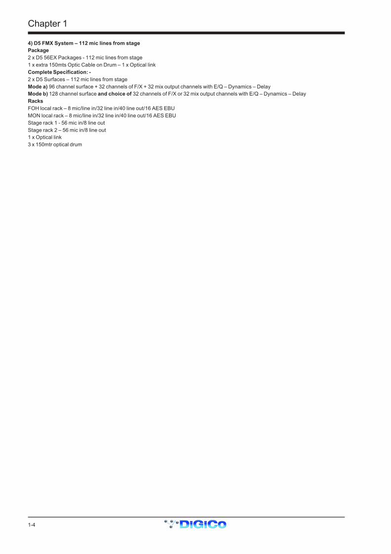
4) D5 FMX System – 112 mic lines from stagePackage2 x D5 56EX Packages - 112 mic lines from stage1 x extra 150mts Optic Cable on Drum – 1 x Optical linkComplete Specification: -2 x D5 Surfaces – 112 mic lines from stageMode a) 96 channel surface + 32 channels of F/X + 32 mix output channels with E/Q – Dynamics – DelayMode b) 128 channel surface and choice of 32 channels of F/X or 32 mix output channels with E/Q – Dynamics – DelayRacksFOH local rack – 8 mic/line in/32 line in/40 line out/16 AES EBUMON local rack – 8 mic/line in/32 line in/40 line out/16 AES EBUStage rack 1 - 56 mic in/8 line outStage rack 2 – 56 mic in/8 line out1 x Optical link3 x 150mtr optical drum

Chapter 1
1-5
1.2 Hardware Configuration
1.2.1 Connections .........................................................................Detailed information on the various systems of connection is provided in the Interconnection and System Setup Manual but thefollowing diagram provides an overview of a single console setup.For Multiple Console Setups see the Appendix.
STAGE RACKS
CONNECTION WITH OPTICAL FIBRE
OPTO A
OPTO ID 30
OPTO ID 20
FOH AUDIO SYNC = OPTO
OPTO ID 32
OPTO A
OPTIONALREDUNDANTLOOP
OPTO A
OPTO B OPTO B
OPTO B
MAIN MADI IN
LOCAL RACK
MAIN MADI OUT
MADI PORT 2 IN
MADI PORT 2 OUT
MAIN MADI IN
CONNECTION WITH MADI
MAIN MADI IN
STAGE RACKS
MADI PORT 1 OUT MADI PORT 3 OUT
MADI PORT 2 OUT
MADI PORT 1 IN MADI PORT 3 IN
MAIN MADI OUT MAIN MADI OUT
FOH AUDIO SYNC = MASTER
MAIN MADI IN
LOCAL RACK
MAIN MADI OUT
MADI PORT 2 IN
MADI PORT 2 OUT
Chapter 1
1-6
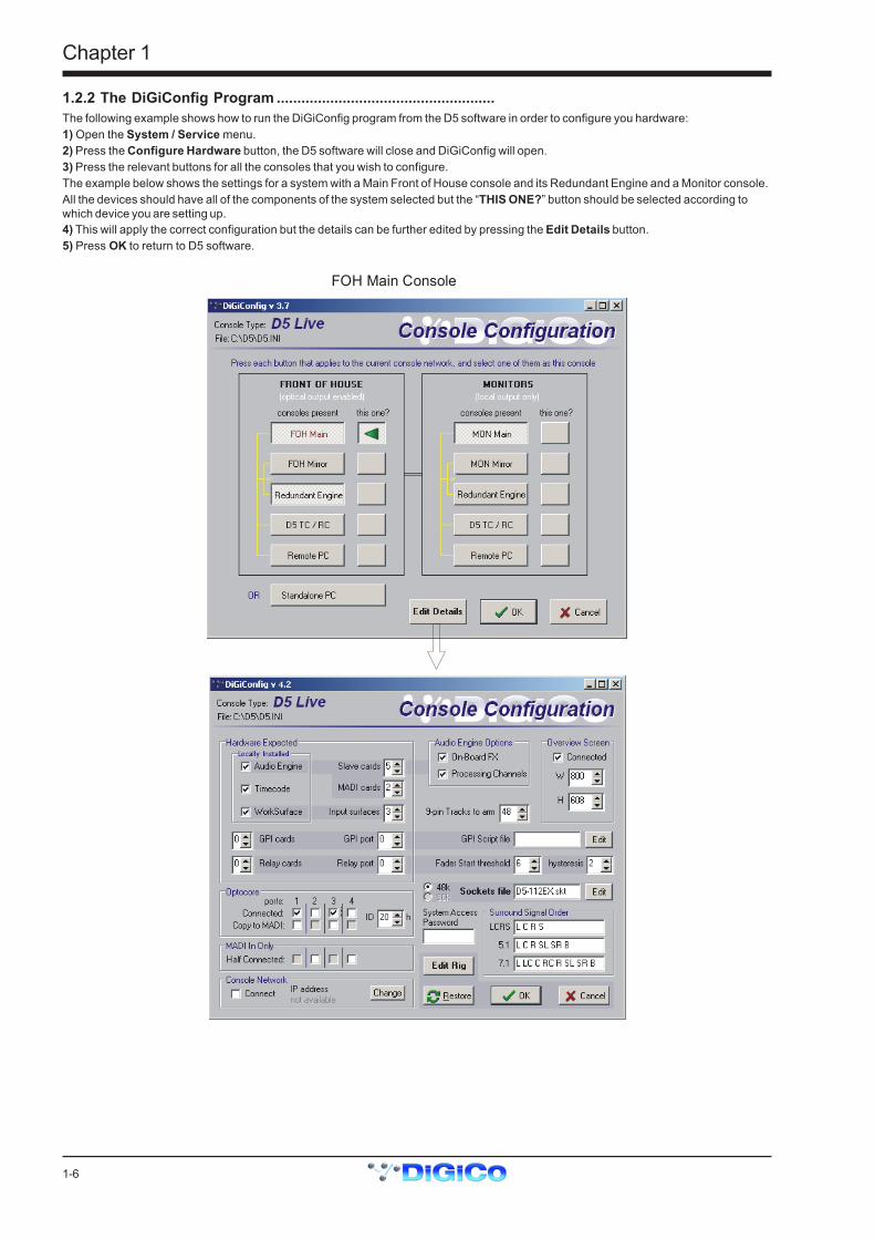
1.2.2 The DiGiConfig Program .....................................................The following example shows how to run the DiGiConfig program from the D5 software in order to configure you hardware:1) Open the System / Service menu.2) Press the Configure Hardware button, the D5 software will close and DiGiConfig will open.3) Press the relevant buttons for all the consoles that you wish to configure.The example below shows the settings for a system with a Main Front of House console and its Redundant Engine and a Monitor console.All the devices should have all of the components of the system selected but the “THIS ONE?” button should be selected according towhich device you are setting up.4) This will apply the correct configuration but the details can be further edited by pressing the Edit Details button.5) Press OK to return to D5 software.
FOH Main Console
Chapter 1
1-7
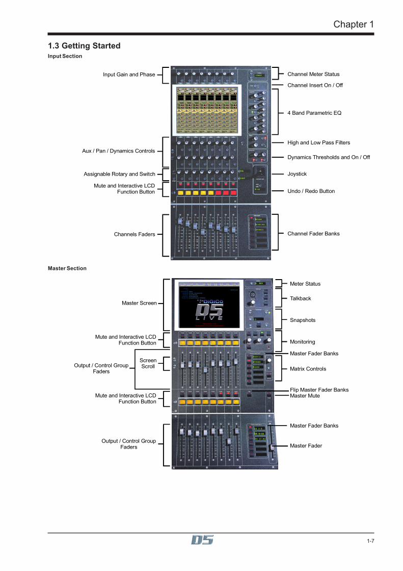
1.3 Getting StartedInput Section
Input Gain and Phase
Aux / Pan / Dynamics Controls
Assignable Rotary and Switch
Mute and Interactive LCDFunction Button
Channels Faders
Channel Meter Status
Channel Insert On / Off
4 Band Parametric EQ
High and Low Pass Filters
Dynamics Thresholds and On / Off
Joystick
Undo / Redo Button
Channel Fader Banks
Master Section
Meter Status
Master Fader Banks
Master Screen
ScreenScroll
Mute and Interactive LCDFunction Button
Output / Control GroupFaders
Talkback
Snapshots
Monitoring
Matrix Controls
Master MuteFlip Master Fader Banks
Master Fader
Mute and Interactive LCDFunction Button
Master Fader Banks
Output / Control GroupFaders
Chapter 1
1-8
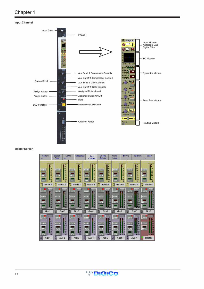
Input Channel
Routing Module
EQ Module
Dynamics Module
Aux / Pan Module
Input ModuleAnalogue GainDigital Trim
Input Gain
Phase
Aux Send & Compressor Controls
Screen Scroll
Assign Rotary
Assign Button
Channel Fader
LCD Function
Aux Send & Gate Controls
Mute
Interactive LCD Button
Aux On/Off & Compressor Controls
Aux On/Off & Gate Controls
Assigned Rotary Level
Assigned Button On/Off
Master Screen
Chapter 1
1-9
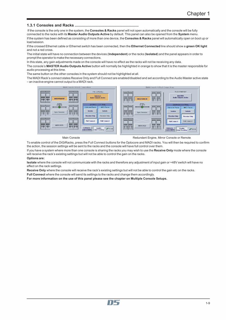
1.3.1 Consoles and Racks ............................................................ If the console is the only one in the system, the Consoles & Racks panel will not open automatically and the console will be fullyconnected to the racks with its Master Audio Outputs Active by default. This panel can also be opened from the System menu.If the system has been defined as consisting of more than one device, the Consoles & Racks panel will automatically open on boot up orload session.If the crossed Ethernet cable or Ethernet switch has been connected, then the Ethernet Connected line should show a green OK lightand not a red cross.The initial state will have no connection between the devices (Independent) or the racks (Isolated) and the panel appears in order toprompt the operator to make the necessary connections.In this state, any gain adjustments made on the console will have no effect as the racks will not be receiving any data.The console’s MASTER Audio Outputs Active button will normally be highlighted in orange to show that it is the master responsible foraudio processing at this time.The same button on the other consoles in the system should not be highlighted at all.The MADI Rack’s connect states Receive Only and Full Connect are enabled/disabled and set according to the Audio Master active state– an inactive engine cannot output to a MADI rack.
Main Console Redundant Engine, Mirror Console or Remote
To enable control of the DiGiRacks, press the Full Connect buttons for the Optocore and MADI racks. You will then be required to confirmthe action, the session settings will be sent to the racks and the console will have full control over them.If you have a system where more than one console is sharing the racks you may wish to use the Receive Only mode where the consolewill receive the rack’s existing settings but will not be able to control the gain on the racks.Options are:Isolate where the console will not communicate with the racks and therefore any adjustment of input gain or +48V switch will have noeffect on the rack settings.Receive Only where the console will receive the rack’s existing settings but will not be able to control the gain etc on the racks.Full Connect where the console will send its settings to the racks and change them accordingly.For more information on the use of this panel please see the chapter on Multiple Console Setups.
Chapter 1
1-10
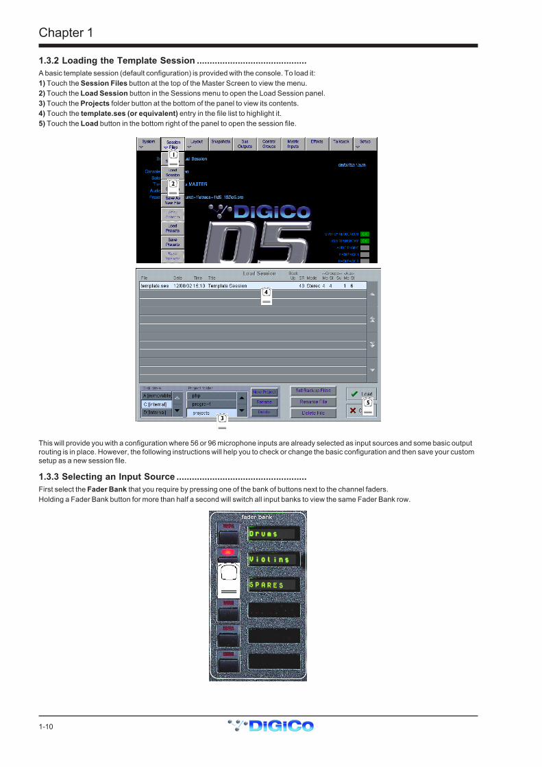
1.3.2 Loading the Template Session ...........................................A basic template session (default configuration) is provided with the console. To load it:1) Touch the Session Files button at the top of the Master Screen to view the menu.2) Touch the Load Session button in the Sessions menu to open the Load Session panel.3) Touch the Projects folder button at the bottom of the panel to view its contents.4) Touch the template.ses (or equivalent) entry in the file list to highlight it.5) Touch the Load button in the bottom right of the panel to open the session file.
1
2
3
4
5
This will provide you with a configuration where 56 or 96 microphone inputs are already selected as input sources and some basic outputrouting is in place. However, the following instructions will help you to check or change the basic configuration and then save your customsetup as a new session file.
1.3.3 Selecting an Input Source ...................................................First select the Fader Bank that you require by pressing one of the bank of buttons next to the channel faders.Holding a Fader Bank button for more than half a second will switch all input banks to view the same Fader Bank row.

Chapter 1
1-11
You can display the Input Module for a fader by touching the top of the fader's on-screen channel strip, where the channel label isdisplayed. You can then hide the module by touching the same area again.
Signal Group Selector
Signal Selector
Signal Label
Preset SelectorPhantom Power(Mic i/p only)
Gain / Phase
Signal Delay
Stereo Channel Mode Selector
Input sources are divided into groups of signals eg. Stage 1-8 or Line 1-16.To select an input source:1) Touch the top of the input screen to open the input panel.2) Touch the name of the Signal Group to view the signal names.3) Touch the name of the signal to assign it to the channel.4) Adjust the gain (analogue rack gain or digital trim selected by touching the required on screen control) with the worksurface rotarycontrol at the top of the channel.5) Touch the top of the input screen again to return to the standard view.Note: Touch the Lab box and type a name for the channel if required.
GAIN1
23
4
5
If the Stereo is pressed, the input channel functions will control two input signals, the one which has been selected and the next one in therack.eg. If Stage 1 is selected and the stereo button is pressed Stage 2 will also be controlled.To Solo a channel use the Channel LCD Buttons just below the mute buttons in the channel strip.
mutemute mute mute mute mute mute mute
PFL
MIC 1
01 MoLCD
FUNCTION
PFL
MIC 2
02 Mo
PFL
MIC 3
03 Mo
PFL
MIC 4
04 Mo
PFL
MIC 5
05 Mo
PFL
MIC 6
06 Mo
PFL
MIC 7
07 Mo
PFL
MIC 8
08 Mo
Chapter 1
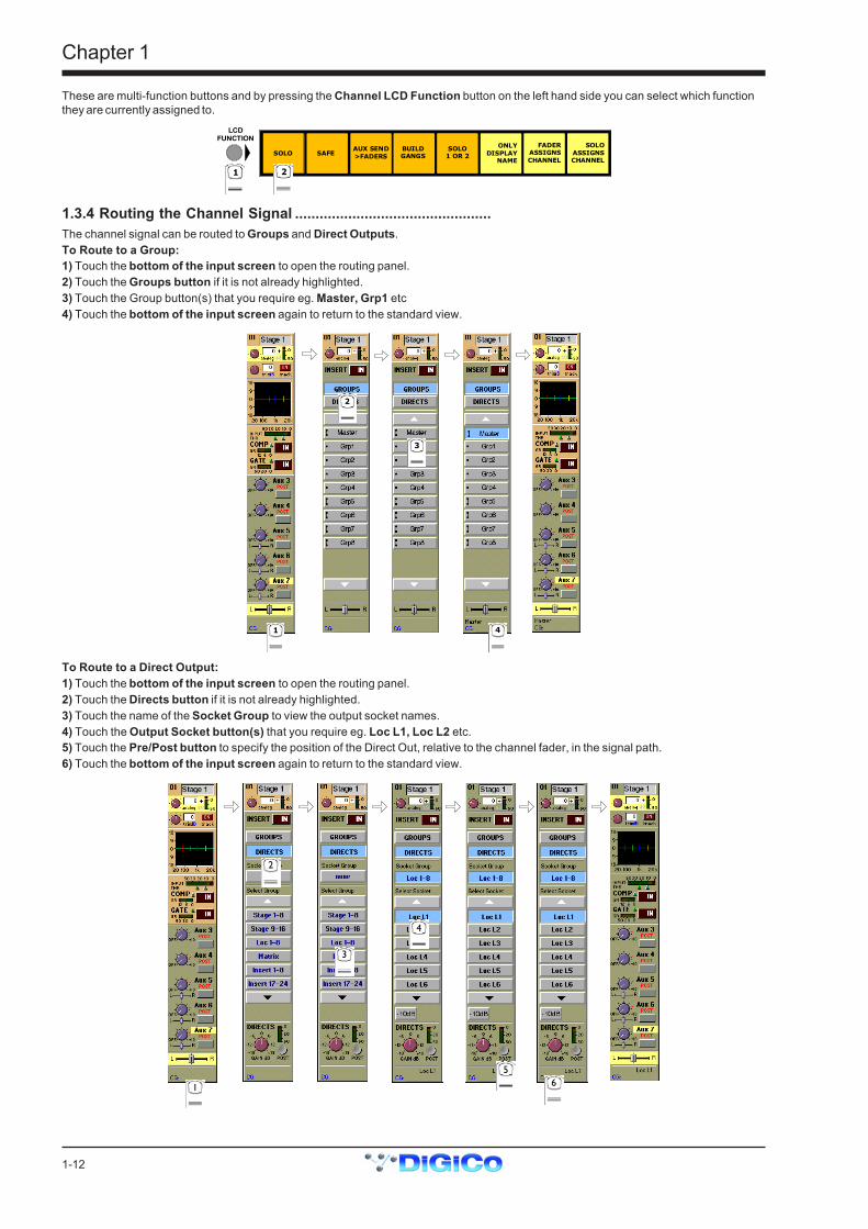
1-12
These are multi-function buttons and by pressing the Channel LCD Function button on the left hand side you can select which functionthey are currently assigned to.
SOLO SAFEAUX SEND>FADERS
BUILDGANGS
FADERASSIGNSCHANNEL
SOLOASSIGNSCHANNEL
LCDFUNCTION
1 2
SOLO1 OR 2
ONLYDISPLAYNAME
1.3.4 Routing the Channel Signal ................................................The channel signal can be routed to Groups and Direct Outputs.To Route to a Group:1) Touch the bottom of the input screen to open the routing panel.2) Touch the Groups button if it is not already highlighted.3) Touch the Group button(s) that you require eg. Master, Grp1 etc4) Touch the bottom of the input screen again to return to the standard view.
2
3
41
To Route to a Direct Output:1) Touch the bottom of the input screen to open the routing panel.2) Touch the Directs button if it is not already highlighted.3) Touch the name of the Socket Group to view the output socket names.4) Touch the Output Socket button(s) that you require eg. Loc L1, Loc L2 etc.5) Touch the Pre/Post button to specify the position of the Direct Out, relative to the channel fader, in the signal path.6) Touch the bottom of the input screen again to return to the standard view.
1
2
4
56
3
Chapter 1
1-13
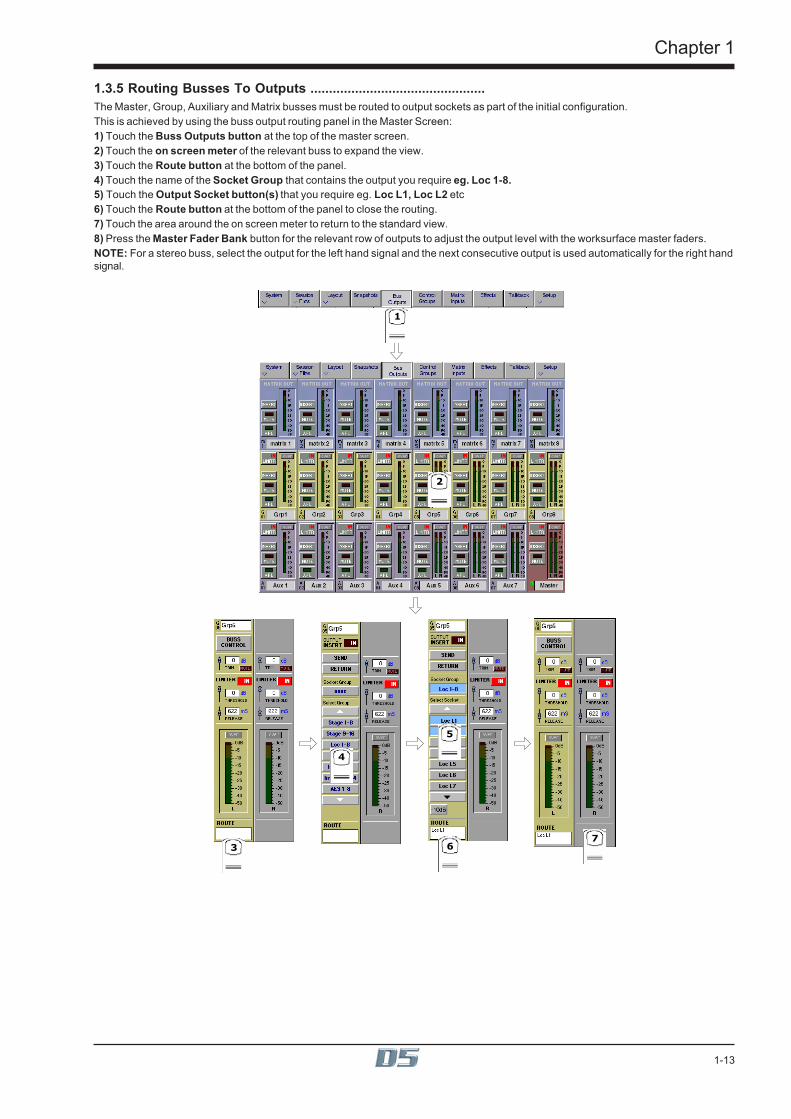
1.3.5 Routing Busses To Outputs ...............................................The Master, Group, Auxiliary and Matrix busses must be routed to output sockets as part of the initial configuration.This is achieved by using the buss output routing panel in the Master Screen:1) Touch the Buss Outputs button at the top of the master screen.2) Touch the on screen meter of the relevant buss to expand the view.3) Touch the Route button at the bottom of the panel.4) Touch the name of the Socket Group that contains the output you require eg. Loc 1-8.5) Touch the Output Socket button(s) that you require eg. Loc L1, Loc L2 etc6) Touch the Route button at the bottom of the panel to close the routing.7) Touch the area around the on screen meter to return to the standard view.8) Press the Master Fader Bank button for the relevant row of outputs to adjust the output level with the worksurface master faders.NOTE: For a stereo buss, select the output for the left hand signal and the next consecutive output is used automatically for the right handsignal.
1
2
3
4
5
67

Chapter 1
1-14
1.3.6 Save As New File ..................................................................When you change the configuration of the template session you should save it to the console's flash drive under a new filename.1) Touch the Session Files button at the top of the Master Screen to view the menu.2) Touch the Save as New File button in the Sessions menu to open the panel.3) Touch the Projects folder button at the bottom of the panel to select the file destination.4) Touch the New Filename box and type the chosen name (with a maximum of 8 letters and no punctuation).5) Touch the Session Title box and type a description of the session if required.6) Touch the Save button in the bottom right of the panel to save the session file.Note: If you touch a session name on the existing list, this name will automatically be selected as the new file name andtouching Save will overwrite the old file.
1
2
3
4 5
6
1.3.7 Save Session ........................................................................This button which is found above the Save As New File button will save the existing session in the same location and under the same filename as it was previously saved or loaded from. It therefore serves as a "Quick Save" option to update an existing session.Remember that this function will overwrite your last saved version.If you wish to save the session under a new name use the Session Files menu button and select Save As New File (See above).
Chapter 1
1-15
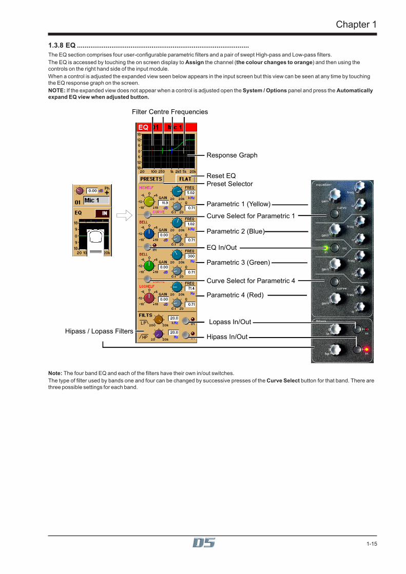
1.3.8 EQ ..........................................................................................The EQ section comprises four user-configurable parametric filters and a pair of swept High-pass and Low-pass filters.The EQ is accessed by touching the on screen display to Assign the channel (the colour changes to orange) and then using thecontrols on the right hand side of the input module.When a control is adjusted the expanded view seen below appears in the input screen but this view can be seen at any time by touchingthe EQ response graph on the screen.NOTE: If the expanded view does not appear when a control is adjusted open the System / Options panel and press the Automaticallyexpand EQ view when adjusted button.
Response Graph
Filter Centre Frequencies
Preset Selector
Parametric 1 (Yellow)
Curve Select for Parametric 1
Curve Select for Parametric 4
EQ In/Out
Parametric 2 (Blue)
Parametric 3 (Green)
Parametric 4 (Red)
Hipass / Lopass Filters
Reset EQ
Lopass In/Out
Hipass In/Out
Note: The four band EQ and each of the filters have their own in/out switches.The type of filter used by bands one and four can be changed by successive presses of the Curve Select button for that band. There arethree possible settings for each band.
Chapter 1
1-16
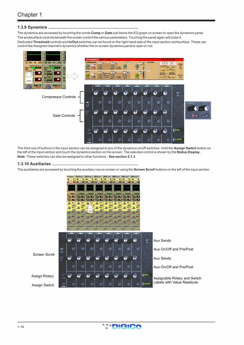
1.3.9 Dynamics ..............................................................................The dynamics are accessed by touching the words Comp or Gate just below the EQ graph on screen to open the dynamics panel.The worksurface controls beneath the screen control the various parameters. Touching the panel again will close it.Dedicated Threshold controls and In/Out switches can be found on the right hand side of the input section worksurface. These cancontrol the Assigned channel's dynamics whether the on screen dynamics panel is open or not.
Gate Controls
Compressor Controls
The third row of buttons in the input section can be assigned to any of the dynamics on/off switches. Hold the Assign Switch button onthe left of the input section and touch the dynamics section on the screen. The selected control is shown by the Status Display.Note: These switches can also be assigned to other functions - See section 2.1.3
1.3.10 Auxiliaries ...........................................................................The auxiliaries are accessed by touching the auxiliary row on screen or using the Screen Scroll buttons on the left of the input section.
Screen Scroll
Aux Sends
Aux On/Off and Pre/Post
Assign Rotary
Assign Switch
Assignable Rotary and SwitchLabels with Value Readouts
Aux Sends
Aux On/Off and Pre/Post

Chapter 1
1-17
Using either of these methods, the highlighted auxiliaries on the input screen will change. The rotary controls and switches beneath thescreen are used as auxiliary sends, pans, on/off and pre/post switches in the following way.
FIRST MONO AUX SEND
SECOND MONO AUX SEND
FIRST MONO AUX ON/OFF(PRE/POST WHEN SEND IS DOWN)
SECOND MONO AUX ON/OFF(PRE/POST WHEN SEND IS DOWN)
STEREO AUX SEND
STEREO AUX PAN
STEREO AUX ON/OFF(PRE/POST WHEN SEND IS DOWN)
STEREO AUX PANTOGGLE TO CENTRE
MONO AUX STEREO AUX
The third rotary control and button in the section can be assigned to any of the auxiliary sends or on/off switches. Hold the Assign Rotaryor Assign Switch button on the left of the input section and touch the required auxiliary row on the screen. The selected auxiliary name isshown by the Assignable Rotary Display.
assign
assign
AND
1.3.11 The Matrix ...........................................................................The 38x8 way matrix is accessed by touching the Matrix Inputs button on the master screen or the Matrix button on the far right of theworksurface master section.Inputs are selected in the same way as the input channels (See Section 1.3.1).Touch the on screen matrix send controls to select which ones you wish to adjust and they will become highlighted.Use the worksurface Matrix Send control and On/Off switch to adjust the settings for all highlighted sends.At the bottom of the panel there are buttons to Clear All Assignment, Load and Save Presets and Scroll buttons to view the otherinputs.
Matrix Send
Send On/Off
Open Matrix
Matrix PresetsClear All Selections Scroll Inputs
1
2

Chapter 1
1-18
1.3.12 Control Groups ..................................................................Any number of input channels and output channels can be connected to one or more of the 24 Control Groups. They can then all beoperated from a single worksurface control. Changes to the Control Group fader, mute or solo or controls will affect all channels con-nected to the group.To set up Control Groups:1) Touch the Control Groups button on the Master screen.2) Touch the Touch Faders To Join/Leave button on the required Control Group (1-24).3) Touch the faders on the channels that you want to include. (Touching the fader again will remove it from the group).4) Touch the Touch Faders To Join/Leave button again to turn the function off.5) Press the on screen Mode button to select Moving faders, VCA style static faders or Mutes only.6) Use the worksurface fader, mute and solo to adjust settings for the Control Group members.
A list of all the connected channels and their names is displayed above each Control Group display, touch the area above the Clear buttonto expand this list.When a fader is touched it is highlighted in the list.You can also clear all the channels from a Control Group by pressing Clear.When a channel is a member of a Control Group, its own controls can still be adjusted independently of the other Group members.Adjustments to fader levels are transmitted to the Group members as dB changes, so that a level increase of 2dB on the Group fader willincrease all the member levels by 2dB, irrespective of the relative levels of the individual channel faders.
Chapter 1
1-19
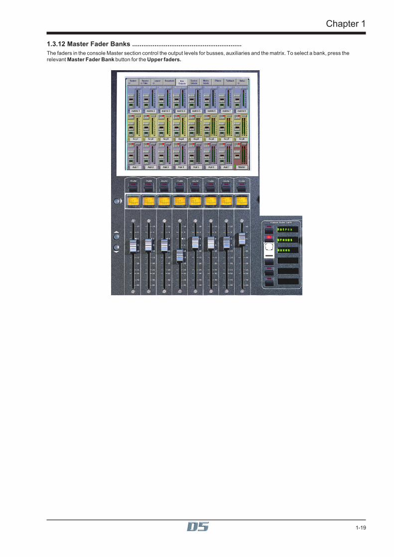
1.3.12 Master Fader Banks ...........................................................The faders in the console Master section control the output levels for busses, auxiliaries and the matrix. To select a bank, press therelevant Master Fader Bank button for the Upper faders.

Chapter 1
1-20
1.3.13 Monitoring ..........................................................................The Monitoring panel can be found under the Setup Menu on the Master Screen and some of the controls can be accessed on the righthand side of the Master worksurface.It may be accessed at any time to change the monitoring setup.
Solo Modes
Assign Solo 2 Levelto Master faderClear All Solos
Monitor Master BussWhen No Solo On
Route Solo 1 To Output Route Solo 2 To Output
Solo 1 Controls
Set Solo 1 Mono Set Solo 2 Mono
Solo 2 Controls
Solo Safe
There are two solo busses and each console solo button can be independently assigned to use Solo 1 or Solo 2. Output solos may use atotal of 16 inputs to each solo buss.Therefore, if the console was being used for stage monitors, the first solo buss could feed an "in ear" monitor and the second solo busscould feed a wedge.To use Solo 2 there must be sufficient busses available (at least two) and if Solo 2 does not appear on the panel a new session should becreated to make these busses available.The dedicated worksurface buttons control the relevant Monitor/Solo 1 functions and the Solo 2 level and trim may be controlled bytouching the on screen control and using the Matrix rotary control on the worksurface.For more information on Monitoring and Solo options see Section 4.2.9.

Chapter 2
2-1
Chapter 2Inputs and Console Channels

Chapter 2
2-2
Chapter 2
2-3
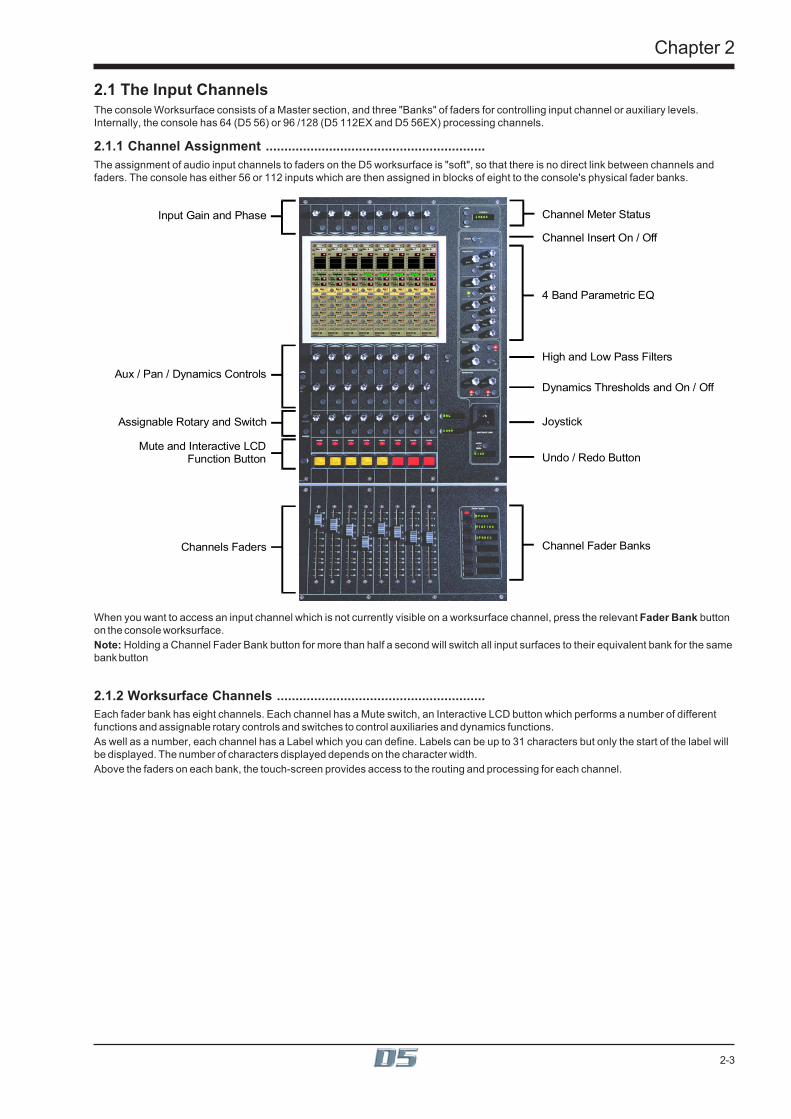
2.1 The Input ChannelsThe console Worksurface consists of a Master section, and three "Banks" of faders for controlling input channel or auxiliary levels.Internally, the console has 64 (D5 56) or 96 /128 (D5 112EX and D5 56EX) processing channels.
2.1.1 Channel Assignment ...........................................................The assignment of audio input channels to faders on the D5 worksurface is "soft", so that there is no direct link between channels andfaders. The console has either 56 or 112 inputs which are then assigned in blocks of eight to the console's physical fader banks.
Input Gain and Phase
Aux / Pan / Dynamics Controls
Assignable Rotary and Switch
Mute and Interactive LCDFunction Button
Channels Faders
Channel Meter Status
Channel Insert On / Off
4 Band Parametric EQ
High and Low Pass Filters
Dynamics Thresholds and On / Off
Joystick
Undo / Redo Button
Channel Fader Banks
When you want to access an input channel which is not currently visible on a worksurface channel, press the relevant Fader Bank buttonon the console worksurface.Note: Holding a Channel Fader Bank button for more than half a second will switch all input surfaces to their equivalent bank for the samebank button
2.1.2 Worksurface Channels ........................................................Each fader bank has eight channels. Each channel has a Mute switch, an Interactive LCD button which performs a number of differentfunctions and assignable rotary controls and switches to control auxiliaries and dynamics functions.As well as a number, each channel has a Label which you can define. Labels can be up to 31 characters but only the start of the label willbe displayed. The number of characters displayed depends on the character width.Above the faders on each bank, the touch-screen provides access to the routing and processing for each channel.
Chapter 2
2-4
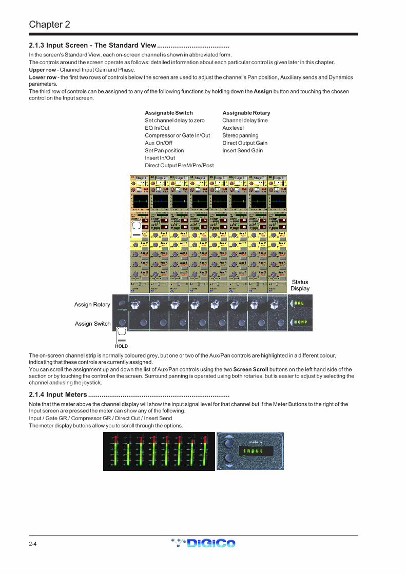
2.1.3 Input Screen - The Standard View......................................In the screen's Standard View, each on-screen channel is shown in abbreviated form.The controls around the screen operate as follows: detailed information about each particular control is given later in this chapter.Upper row - Channel Input Gain and Phase.Lower row - the first two rows of controls below the screen are used to adjust the channel's Pan position, Auxiliary sends and Dynamicsparameters.The third row of controls can be assigned to any of the following functions by holding down the Assign button and touching the chosencontrol on the Input screen.
Assignable Switch Assignable RotarySet channel delay to zero Channel delay timeEQ In/Out Aux levelCompressor or Gate In/Out Stereo panningAux On/Off Direct Output GainSet Pan position Insert Send GainInsert In/OutDirect Output PreM/Pre/Post
Assign Rotary
Assign Switch
StatusDisplay
HOLD
The on-screen channel strip is normally coloured grey, but one or two of the Aux/Pan controls are highlighted in a different colour,indicating that these controls are currently assigned.You can scroll the assignment up and down the list of Aux/Pan controls using the two Screen Scroll buttons on the left hand side of thesection or by touching the control on the screen. Surround panning is operated using both rotaries, but is easier to adjust by selecting thechannel and using the joystick.
2.1.4 Input Meters ..........................................................................Note that the meter above the channel display will show the input signal level for that channel but if the Meter Buttons to the right of theInput screen are pressed the meter can show any of the following:Input / Gate GR / Compressor GR / Direct Out / Insert SendThe meter display buttons allow you to scroll through the options.

Chapter 2
2-5
2.1.5 Assigning a Channel ...........................................................To assign one of the on-screen channels so that you can adjust the EQ or Dynamics settings or use the Joystick, touch the on-screendisplay of the channel anywhere in the EQ or Dynamics area. (Not on the In / Out switches)The background colour of the channel changes to show that it is selected.Touching the IN /OUT buttons will switch the relevant processing module ON or OFF.
There is also an option to assign a channel by either touching its fader or pressing its solo button. See Section 2.2.8 Channel LCDFunction Buttons.
2.2 Expanding a Processing ModuleOnce you have selected a channel, you can choose to view any of the processing Modules in more detail by touching the abbreviateddisplay of the section. There are five areas of the channel you can touch to see the module in more detail:
Input ModuleAnalogue GainDigital Trim
Routing Module
EQ Module
Dynamics Module
Aux / Pan Module

Chapter 2
2-6
2.2.1 Input Module ........................................................................You can display the Input Module for a fader by touching the top of the fader's on-screen channel strip, where the channel label isdisplayed. You can then hide the module by touching the same area again.
Signal Group Selector
Signal Selector
Signal Label
Preset SelectorPhantom Power(Mic i/p only)
Gain / Phase
Signal Delay
Stereo Channel Mode Selector
The Input Module contains the following controls:
Channel LabelTo alter the Label, touch the Label area, then type the new label on the keyboard. Labels can be up to 31 characters long, but only thestart of the label will be displayed depending on the character width.
Signal GroupThe input sockets are arranged into named "Groups". To display the signal groups, touch the Signal Group Selector area as shownabove. You can then touch the button for the group you want.
"Misc" Signal GroupThe Misc group contains the console's internal signal sources and sockets, including signals from the worksurface and rear Talkbackmicrophones, and the internal Noise and Tone generators.The original talkback sources (the unprocessed microphone inputs) are labelled Talk Mic L (Top) & R (Rear).The post-processing results from the talkback input channels are labelled Talkback A & B.
Select Signal - Signal in GroupTo select a source, touch the button for the signal you want to connect to the channel. If there are more than five channels in the group,you may need to use the scroll buttons (top and bottom) to display the button for the signal you want.
Stereo Channel Mode Selector
Signal Label
Gain / Phase
Stereo Channel Mode SelectorIf this button is pressed, the input channel functions will control two input signals, the one which has been selected and the next one in therack.Input source, Direct output, Insert Send and Insert Return will all function as adjacent pairs so making a selection for the left signal willresult in an automatic selection for the right signal.

Chapter 2
2-7
Processing for the right signal is taken from the highest numbered channel available which has no input route or insert return routeselected. The channel which is used will no longer be available for normal operation. This is indicated by a white channel number.Stereo channels show all signal meters as pairs. Gain reduction meters in dynamics are also shown as pairs, but with the dynamicsstereo link switched on, only the larger gain reduction of the pair is used for both sides of the stereo channel. The meter bridge shows twopeaks for stereo inputs.The stereo channel display will change in the following way:
MS Decode Swap Left and Right SignalsInput Balance
The following additional functions are made available:
MS DecodeThis button will activate MS Decoding for the stereo signal
Swap (Reverse) Left and Right SignalsThis button will reverse the left and right signals or the Middle and Side signals if MS Decoding is active.
Input BalanceControls the relative levels of left and right signals in the stereo pair.NOTE: Most of the channel settings are preserved when switching from Mono to Stereo or vice versa. Pans are reset andstereo routing may not be correct if the relevant output sockets are unavailablePhantom Power only appears if the channel's source signal is a microphone.When you connect to a Microphone input, a Phantom Power switch appears in the Input Routing Module. Phantom Power operates at+48V. The default setting of this button can be controlled in the "Sockets File".
Channel PresetsThe Channel Presets button allows you to store or recall a complete channel setup. A Channel Preset contains all the channel controlsfrom the Input Gain to the Pan and Fader positions and group routing. Note that a channel preset does NOT include any input socketrouting information - this must be set specifically for each channel.When you press the Channel Preset button, the screen displays a Preset Selector:
To Recall an existing channel preset, simply touch the preset you want. If the preset is not visible, you can touch the vertical arrows toscroll the list up or down. The preset settings are implemented in the channel as soon as you touch it.To store the current channel settings as a New preset, touch the New button, then type a name for the new preset.To Replace an existing preset with the current settings, touch the Store button, then touch the name of the preset you want to overwrite.To Rename an existing preset without changing its settings, touch the Rename button, then touch the preset you want to rename, andtype the new name.To Delete a preset, touch the Delete button, then touch the name of the preset you want to delete.The Default button forces all controls on the channel to their default settings. This will normally mean flat EQ, inactive dynamics, centralpan, Aux sends at zero, and fader at 0dB.The Close button removes the Preset Selector from the screen, but has no direct effect on the channel settings.

Chapter 2
2-8
Gain, Phase and DelayWhen the Input module is expanded, the rotaries and switches in the Lower Row of input bank controls (immediately below the channeldisplay) control the Delay settings for mono channels or Input Balance and Delay for stereo channels.In addition, Gain and Phase adjustment is always available using the controls above the Inputs Screen.The Input Gain control provides a basic level trim. If the input source is an analogue input socket, the Gain setting controls the analogueamplifier which sets the incoming signal level before conversion to digital. The Phase switch allows +/- phase settings.There is also digital trim control which can be accessed by touching and it will be highlighted in yellow. In this state, the button at the top ofthe channel serves as a Gain Tracking On/Off switch (See the chapter entitled Multiple Console Setups for more information)On mono or stereo channels you can use the Delay control to delay the input signal by up to 240ms. There is also a Delay On/Off switch.
2.2.2 Equaliser Module .................................................................The EQ module comprises four user-configurable parametric filters.There is also a pair of swept High-pass and Low-pass filters. If the EQ module is not expanded, the EQ can be switched On or Off withthe In / Out button above the EQ graphTo expand the EQ Module for a channel, first select the channel, then touch the channel's EQ graph. To hide the module again, touch theexpanded EQ graph.Note: The EQ panel can be expanded automatically when an EQ control is adjusted by setting System Menu / System Options:

Chapter 2
2-9
Response Graph
Filter Centre Frequencies
Preset Selector
Parametric 1 (Yellow)
Curve Select for Parametric 1
Curve Select for Parametric 4
EQ In/Out
Parametric 2 (Blue)
Parametric 3 (Green)
Parametric 4 (Red)
Hipass / Lopass Filters
Reset EQ
Lopass In/Out
Hipass In/Out
When expanded, the EQ Module shows the filter settings in detail, using a different colour for each filter. The In/Out switch and indicatorfor the EQ module is located in the centre. When the EQ module is visible, the EQ controls at the right side of the screen operatecorresponding to the on-screen controls.
Preset SelectorPresets are used not only for complete channel setups, but also for EQ and Dynamics setups. They provide a way of storing the EQsettings for a particular channel, so that these settings can be recalled instantly at a later date, or for another channel.Touching the EQ module's Presets button displays a Selector panel for the EQ presets. The panel works in exactly the same way as theChannel Preset Selector described earlier in this section (see 2.2.1), although an EQ preset only contains settings for the EQ controls, notfor the whole channel.
Flat ButtonThe Flat button forces all gain controls on the channel's EQ section to their default settings.
EqualisersFilters two and three (blue and green) are swept parametric "bell-curve" equalisers, with a centre-frequency range of 20Hz-20KHz. Theyprovide up to 18dB Cut/Boost, with Q adjustable from 0.1 to 20.Filters one and four (yellow and red) default to being a Hi and Low Shelf but each has an additional Curve switch which allows you toselect HiShelf / Lowpass or Bell for filter one and LoShelf / Hipass or Bell for filter four. When the Hipass or Lowpass function is selected,the filter operates at 12dB/Octave, and the Q and Gain controls disappear.
Hipass / Lopass FiltersThe Hipass and Lopass filters at the bottom of the module (purple and orange) operate at 12dB/Octave, and can be swept from20Hz-20KHz (HPF) and 200Hz to 20KHz (LPF).Note: The Hi and Lo Pass Filters are positioned preprocessing and therefore they will be unavailable to any internally gener-ated signal such as the test noise.These internally generated signals consist of:1) Any signal in the Misc signal group (Talkback Mics, Test Tone and Noise).2) Group or Aux Buss results (labelled with a ~ eg ~ Aux1 L).3) Internal FX Returns (any signal from the Effects input signal group which is used by the optional effects module).

Chapter 2
2-10
2.2.3 Dynamics Module.................................................................The Dynamics Module on each channel incorporates a Compressor and Gate, and also includes optional Filters for the sidechain and keysignals.You can display the Dynamics Module by touching the dynamics display on the channel strip. Touching the In / Out buttons will switch thesection On or Off.When expanded, the Dynamics Module appears across the bottom of the screen, and its settings are changed using the correspondingcontrols below the display.
Gate Controls
Compressor Controls
CompressorThe Threshold is the level at which the compression begins to affect the signal. For example, if you set the Threshold to -12dB, thismeans that the compressor has no effect until the signal level exceeds -12dB.The Attack time is the time taken for the attenuation to reach the desired level after an increase in the level of the input signal.The Decay time is the time taken for the attenuation to reach the desired level after a decrease in the level of the input signal.The Ratio control lets you set the ratio between the signal level change and the resulting attenuation change. For example, if you set theRatio to 2:1, and the signal is above Threshold, a 6dB increase in level will result in a 3db increase in attenuation, so the net effect on theaudio signal will be a level increase of 3dB.The Gain control allows you to boost the overall level of the audio signal coming out of the compressor, to make up any level lost throughcompression.The Meter provides a constant indication of the compressor gain reduction.The Sidechain Solo places the Sidechain signal on the Solo buss in PFL (Mono) mode. This is achieved by holding down the corre-sponding button in the compressor controls below the screen.
GateThe Threshold is the signal level above which the Gate has no effect.The Attack time is the time the Gate takes to open once the signal level has risen above threshold.The Decay time sets the time the Gate takes to close, once the signal level has dropped below the threshold (and the Hold time haspassed - see next paragraph). A long decay time means that the attenuation increases gradually, making any sub-threshold signal fadeout. A short decay time means that the Gate shuts quickly, cutting off the signal abruptly.The Hold time is an extra period for which the Gate remains open after the signal level has dropped below threshold.The Range control sets the maximum amount of signal attenuation implemented by the Gate when it is closed (ie when the signal level isbelow threshold). A Range setting of 0dB means that the Gate has no effect, while a Range setting of 30dB means that all signal levelsbelow threshold will be attenuated by -30dB.The Meter provides a constant indication of the Gate attenuation. If the Gate is fully open, the meter shows full deflection, indicating 0dBattenuation. If the Gate is fully closed and the Decay and Hold times have passed, the meter shows the amount of attenuation set by theRange control.The Gate Key button allows you to select the signal used to trigger the Gate. The default setting is Self, where the level of the channel'sown signal is used as the trigger, but you can use this switch choose a different channel or buss.Pressing the Gate Key button in the Dynamics panel displays a routing panel from which to select a key source. All input signals and bussresults are listed as well as input channel post-processed signals.Note: The Signal Group labelled Channels contains the post-processed signals.Gate Key signals use the channel send resource just like direct output and insert sends. This resource is limited to 96 channels and whenall 96 are used up, other channels listed will be greyed out. The state of channel send resources is displayed on the diagnostics panel.Note: When the Filters are switched into the Dynamics section the Gate Key Source is automatically switched to its "Self"setting and disabled.

Chapter 2
2-11
The Key Solo places the Key Source signal on the Solo buss in PFL (Mono) mode. This is achieved by holding down the correspondingbutton in the gate controls below the screen.
Configuration and FiltersThe default structure for the Dynamics Module is a simple Compressor-Gate layout, but you can also select from four other structures, ororders of effect processing, and use filters to achieve frequency-sensitive keying of the dynamics. The filters are a pair of second-order(12dB/Octave) High-Pass and Low-Pass filters, which can be swept between 20Hz and 20KHz.
You can select any of the structures just by touching them on the screen, and all the structure options except the default top one use theHipass and Lopass filters. The filter roll-off frequencies are controlled by the rotaries directly below the on-screen controls.Note that the filters cannot be used on an external trigger source.
In this configuration, the filters are used in the side chain of the compressor to provide frequency conscious compression effects such asde-essing.
In this configuration, the filters are used in the side chain of the gate to provide frequency conscious gating.
In this configuration, the filtered signal feeds the input of the gate while other frequencies bypass the gate. This allows for a specific bandof frequency to be gated and then mixed back into the remaining band.
In this configuration, the filtered signal feeds the input of the compressor while other frequencies bypass the compressor. This allows for aspecific band of frequency to be compressed and then mixed back into the remaining band.
Dynamics PresetsTouching the Dynamics module's Presets button displays a Selector panel for the Dynamics presets. The panel works in exactly thesame way as the Channel Preset Selector described earlier in this section (see Section 2.2.1), although a Dynamics preset only containssettings for the Dynamics controls, not for the whole channel.
Dynamics LinkingThe Gate and Compressor modules may be linked in adjacent channels to produce a stereo mixed control voltage, ensuring both channelsrespond identically.Press the Stereo Link switch on the right hand side of the Dynamics panel. Both sides of the pair are switched simultaneously.Note: The switches are not included in snapshots or presets.In a stereo channel, the stereo link switch is pressed by default.

Chapter 2
2-12
2.2.4 Pan / Aux Module .................................................................The Aux Send and Pan controls are always operated using the Lower Row of rotaries below each channel of the on-screen display. Thereare only two rotaries and switches for each channel, but these can be assigned to any Aux or Pan control using the Screen Scroll buttonsat the left end or by touching the on-screen control that you wish to adjust. The current assignment of the controls is indicated by ahighlight on the screen.To expand the display to show more auxiliaries on screen touch the highlighted control.To return to the standard view touch the highlighted control again.Note: Holding the All button on the worksurface and touching the highlighted control will expand the view for all the channels in therelevant bank.
Screen Scroll
Aux Sends
Aux On/Off and Pre/Post
Assign Rotary
Assign Switch
Assignable Rotary and SwitchLabels with Value Readouts
Aux Sends
Aux On/Off and Pre/Post
The Pan/Aux controls and scroll buttons operate in exactly the same way in both the Standard and the Expanded view.
AuxiliariesThe console can support up to 28 Mono or 18 Stereo Auxiliaries, depending on the availability of bussing resources. Auxiliaries can bemono or stereo, and stereo Auxiliaries have a Pan control as well as the normal Send Level control.The Aux send rotaries below the screen operate differently depending on the Aux format. For mono Aux sends, each row of rotariescontrols a different send level, but for a stereo Aux send, the two controls are used for send level and pan position for that Aux. Asalways, the assignment of the rotary controls below the screen is clearly indicated by the highlight on the relevant screen controls, and youcan always use the Screen Scroll buttons to access the control you require.
Aux Pre / Post and On / Off SwitchingEach Aux Send rotary control in the Lower Row has an associated switch, which operates both the Mode and On/Off function for that Aux.
If the level control is set to zero (as Aux 1 above), the switch controls the Mode setting for that Aux. As soon as the level control is movedabove zero (Aux 2 above), the switch becomes an On/Off switch for that Aux send. So to change the Mode setting for an Aux, you mustfirst reduce the level on that Aux Send to zero.There are 3 possible Modes:PRE M = Pre Mute and Pre FaderPRE = Post Mute and Pre FaderPOST = Post Mute and Post FaderSee Aux Buss Control in Chapter 3 for global mode changes.

Chapter 2
2-13
Pan ControlPanning to the Master and Group busses is Stereo or Surround, depending on the console configuration. Pan position for each channelcan be controlled in two ways: by using the rotary controls in the Lower Row below the on-screen channel display, or by Selecting thechannel and using the Joystick. For surround panning, the Joystick is much more intuitive than using a pair of rotary controls.
Surround PanningWith Surround console formats, in addition to the surround Pan control, there are two additional controls for LR/LCR and Sub in 5.1format and one control for LR/LCR in LCRS format.
When using the Joystick to Pan the Selected channel, you will find that the Joystick position is shown on the Pan control as a pair ofgreen lines. Moving the Joystick moves these lines, but does not move the Pan position of the channel itself until the green lines travelover the real Left-Right or Front-Back pan position. Once the Joystick position has passed through the real Pan position, further move-ment of the Joystick will then alter the Pan position in the normal way.When using the rotaries for surround panning, the upper rotary controls the Left-Right position, and the lower rotary controls Front-Back.
Preset Pan PositionsThe upper button directly below the pan rotaries can be used to reset panning positions.In a stereo console it will switch panning between left, centre and right positions with successive presses. In LCRS and 5.1 consoles thebutton works in a similar way for each available position.Panning Stereo ChannelsWhen an input channel is stereo and therefore controlling a pair of input signals the pan control will appear in one of the following ways.In a stereo console configuration the upper rotary serves as a width control with the full left position being mono, the centre position beingnormal stereo and the full right position being wide stereo. The width control is accessed by scrolling down past the pan. The lower rotaryserves as a balance control between the relative levels of the stereo pair.
The surround panner for stereo inputs simultaneously controls the position of both left and right signals. The joystick and wheel directlycontrol the position of the left signal, and the right signal is automatically mirrored on the left-right axis. A red indicator shows the positionof the right signal. This provides some control of width. The signals can also be crossed to reverse the stereo image.When panned to centre, left and right will be mono. Front-back, Sub and LR/LCR are always identical for both left and right signals.
LR/LCR Blend and SubThe LR/LCR and Sub controls can be adjusted using the normal Pan/Aux rotaries below the screen - use the Screen Scroll buttons tomove the highlight down from the Pan control to highlight LR/LCR and Sub.
The LR/LCR Blend control adjusts the type of Panning that is applied when sending to Surround busses.It blends a normal stereo panner with an LCR panner by varying amounts, allowing control of how much L & R is fed into C. The default isfull LCR in a New Session, but note that when loading older surround sessions the level is taken from the old Divergence control, whichdefaulted to hard left (= full LR).A Blend setting of LR (Full left) only allows LR panning with no signal going to the C buss whilst a setting of LCR (full right) allowspanning between L and C up to the control's centre position and panning between C and R thereafter.The Sub control is only present on 5.1 console configurations. It is a trim control with unity gain at the centre position for sending thesignal to the Sub channel of a surround buss or output.Controlling the Sub FeedWhen a Sub control is present the lower button directly below the pan rotaries switches between three different states for controlling theSub Feed. Successive presses of the button will change to the following states:LCRSS on - The signal can go to all busses except the sub buss according to the channel pan position. (Default mode)Sub on - The signal can only go to the Sub Buss. (Indicated by a B in the display)All on - The signal can go to all busses including the Sub Buss. (Indicated by LCRSS and B in the display)The current state is indicated by letters in the background of the pan control display.NOTE: This control is contained in snapshots and channel presets. It is part of the Panning Scope for Snapshots.

Chapter 2
2-14
2.2.5 Routing Module ....................................................................At the bottom of the input channel display is the Routing Module. This gives an abbreviated display of the current channel routing - on theleft, the Master and Group routing, and on the right (if the channel is routed to a Direct Output) the name of the Direct Output socket. Asthe screen only has enough space to display one buss name, the routing of the channel to additional Groups is indicated by dots...If the channel is a member of a Control Group, the name of that group also appears here.
Routed to Master and othergroup(s) - no direct routing
Routed to Master only andDirect routed to a socket
called "Line 1"Displaying the Routing ModuleTouching the bottom of the channel displays the full Routing module, which controls the buss routing for the signal. To hide the RoutingModule, touch the same area again.The Routing Module allows you to select the console Group and/or Direct output socket routing for the channel.

Chapter 2
2-15
Group RoutingWhen the Groups button is selected, the on-screen group buttons allow you to connect the channel to any number of output groupbusses - mono groups are displayed with a single dot (groups 1-4 in the diagram below), while stereo or surround busses appear with adouble dot (groups 5-8). To connect or disconnect the signal, simply press the on-screen button for the relevant group.The number and type of groups depends on the console configuration.
Direct OutputsYou can also choose to route the channel signal directly to any of the console's output sockets, by touching the Directs button. This showsa display of the console's Output sockets, so that you can select any number of sockets for the Direct Out.
Output Socket Group Selector
Pre/Post Fader Switch
Level Trim & Meter
Directs Selector
Output Socket Selector
Minus 10dB Output Switch
A Direct Output can operate in one of three modes:PRE M = Pre Mute and Pre FaderPRE = Post Mute and Pre FaderPOST = Post Mute and Post FaderIts level can be trimmed by +/-18dB and a -10dB pad can be applied.

Chapter 2
2-16
Insert Routing and On/Off SwitchThis button controls the routing for the input channel insert send and return selection.Touching the Insert button displays a panel which allows you to select Send and Return sockets in the same way as you would select anInput socket or a Direct output. There is also a Send Gain control providing a trim of +/-18dB.
Socket Group Selector
Pre/Post EQ/Dynamics SwitchLevel Trim & Meter
Touch to Select Send Socket
Socket Selector
Insert On/Off
Insert On/Off
Touch to Select Return Socket
Touch Here to Open / Close Panel
Worksurface Control
The Insert can be PRE or POST EQ and Dynamics switched by the button just above the Send Gain.If you touch the In button, the channel's signal is taken from the Insert Return socket and thus switches the insert on.The In button is also on the console worksurface on the top right hand side of the input screen.Note: If the insert is switched on but a socket has not been assigned for the insert return then there will be no signal audible inthe channel.

Chapter 2
2-17
2.2.6 The ALL Button ....................................................................The All button provides a quick way of displaying all the Input, Aux or Routing modules for a bank of eight channels. If you hold down theAll button while touching the Input, Routing or Aux modules, the expanded view of the relevant module is displayed for all the visiblechannels.
You can also scroll through lists using the All button. For example, if you wanted to select several input sources from the same group,holding All and pressing the scroll arrow on one channel would scroll the adjacent channels as well.In the Routing window holding the All button will also allow you to perform the following tasks:1) Selecting Group or Direct routing for all the channels in the bank.2) Scrolling Up and Down through lists.3) Routing Input sources to consecutive channels without making them part of a gang.4) Routing all channels in a bank to the same group by holding all and routing the first one.5) Routing all the channels in a bank to consecutive direct outputs by holding all and routing the first one.6) Routing all the channels in a bank to consecutive insert sends/returns by holding all and routing the first one.NOTE: In examples 3, 4, 5 and 6 the functions are limited to consecutive channels in the same view mode.
2.2.7 Undo / Redo Button .............................................................While a channel is assigned to the EQ/Dynamics/Joystick controls, the Undo/Redo LED comes on when a control is changed andpressing the button toggles between the new state and the state when assigned.The controls affected by the undo function are input gain, phase and delay, all EQ and dynamics, all aux send levels, on/off buttons andpans, the insert and the main pan for the channel. It does not include any routing buttons.
2.2.8 Channel LCD Function Buttons .........................................Pressing the Channel LCD Function button on the left hand side of the Input Section allows you to select the function that the individualChannel LCD Buttons are currently assigned to.
SOLO SAFEAUX SEND>FADERS
BUILDGANGS
FADERASSIGNSCHANNEL
SOLOASSIGNSCHANNEL
LCDFUNCTION
1 2
SOLO1 OR 2
ONLYDISPLAYNAME
The default function is Solo.To Solo a channel use the Channel LCD Buttons just below the mute buttons in the channel strip.
mutemute mute mute mute mute mute mute
PFL
MIC 1
01 MoLCD
FUNCTION
PFL
MIC 2
02 Mo
PFL
MIC 3
03 Mo
PFL
MIC 4
04 Mo
PFL
MIC 5
05 Mo
PFL
MIC 6
06 Mo
PFL
MIC 7
07 Mo
PFL
MIC 8
08 Mo
Note: The console has the option of two Solo busses - See Monitoring in Chapter 4 for more details.

Chapter 2
2-18
There is also an option to assign a channel by either touching its fader or pressing its solo button.To activate either of these functions:Press the Channel LCD Function button on the left of the input section and then press the Fader Assigns Channel and/or SoloAssigns Channel buttons. When the function is activated, the button appears with a tick in its display.Press the Solo button again to return to the standard view.
MIC 1
01 MoLCD
FUNCTION
SOLO SAFEAUX SEND>FADERS
BUILDGANGS
FADERASSIGNSCHANNEL
SOLOASSIGNSCHANNEL
MIC 2
02 Mo
MIC 3
03 Mo
MIC 4
04 Mo
MIC 5
05 Mo
MIC 6
06 Mo
MIC 7
07 Mo
MIC 8
08 Mo
LCDFUNCTION
1
2
PFL PFL PFL PFL PFL PFL PFL PFL
SOLO SAFEAUX SEND>FADERS
BUILDGANGS
FADERASSIGNSCHANNEL
SOLOASSIGNSCHANNEL
LCDFUNCTION
3
MIC 1
01 MoLCD
FUNCTION
MIC 2
02 Mo
MIC 3
03 Mo
MIC 4
04 Mo
MIC 5
05 Mo
MIC 6
06 Mo
MIC 7
07 Mo
MIC 8
08 Mo
PFL PFL PFL PFL PFL PFL PFL PFL
ONLYDISPLAYNAME
ONLYDISPLAYNAME
SOLO1 OR 2
SOLO1 OR 2
The Only Display Name option changes the appearance of the Channel LCD buttons when they are in Solo Mode to show the ChannelName in a large easy to read font.To activate this function:Press the Channel LCD Function button on the left of the input section and then press the Only Display Name button. When thefunction is activated, the button appears with a tick in its display.Press the Solo button again to return to the standard view.
MIC 1
01 MoLCD
FUNCTION
SOLO SAFEAUX SEND>FADERS
BUILDGANGS
FADERASSIGNSCHANNEL
SOLOASSIGNSCHANNEL
MIC 2
02 Mo
MIC 3
03 Mo
MIC 4
04 Mo
MIC 5
05 Mo
MIC 6
06 Mo
MIC 7
07 Mo
MIC 8
08 Mo
LCDFUNCTION
1
2
PFL PFL PFL PFL PFL PFL PFL PFL
SOLO SAFEAUX SEND>FADERS
BUILDGANGS
FADERASSIGNSCHANNEL
SOLOASSIGNSCHANNEL
LCDFUNCTION
3
MIC 1
LCDFUNCTION
MIC 2 MIC 3 MIC 4 MIC 5 MIC 6 MIC 7 MIC 8
ONLYDISPLAYNAME
ONLYDISPLAYNAME
SOLO1 OR 2
SOLO1 OR 2
The Safe function makes selected channels safe from all Snapshots.1) Press the Channel LCD Function button2) Press the Safe button.3) Press the Channel LCD buttons for the channels that should be Safe (The buttons and screen channel strip will turn red).4) Press the Channel LCD Function button to exit Safe mode.5) Press the Solo function button to return to the standard view.
MIC 1
01 MoLCD
FUNCTION
MIC 2
02 Mo
MIC 3
03 Mo
MIC 4
04 Mo
MIC 5
05 Mo
MIC 6
06 Mo
MIC 7
07 Mo
MIC 8
08 Mo
LCDFUNCTION
1 PFL PFL PFL PFL PFL PFL PFL PFL
MIC 1
01 MoMIC 2
02 Mo
MIC 3
03 Mo
MIC 4
04 Mo
MIC 5
05 Mo
MIC 6
06 Mo
MIC 7
07 Mo
MIC 8
08 Mo
SAFE SAFE SAFE SAFE SAFE SAFE SAFE SAFE
LCDFUNCTION
3 4 56
LCDFUNCTION
MIC 1
01 MoLCD
FUNCTION
MIC 2
02 Mo
MIC 3
03 Mo
MIC 4
04 Mo
MIC 5
05 Mo
MIC 6
06 Mo
MIC 7
07 Mo
MIC 8
08 Mo
PFL PFL PFL PFL PFL PFL PFL PFL
SOLO SAFEAUX SEND>FADERS
BUILDGANGS
FADERASSIGNSCHANNEL
SOLOASSIGNSCHANNEL
ONLYDISPLAYNAME
SOLO1 OR 2
SOLO SAFEAUX SEND>FADERS
BUILDGANGS
FADERASSIGNSCHANNEL
SOLOASSIGNSCHANNEL
ONLYDISPLAYNAME
SOLO1 OR 2
7
2
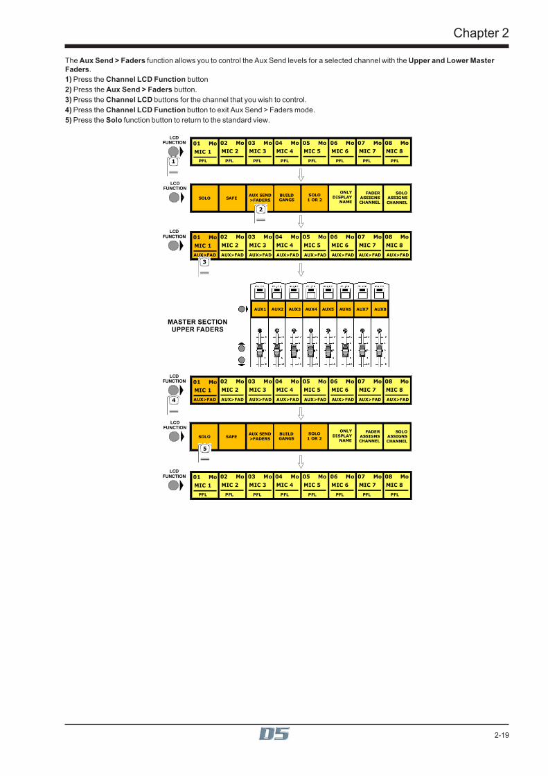
Chapter 2
2-19
The Aux Send > Faders function allows you to control the Aux Send levels for a selected channel with the Upper and Lower MasterFaders.1) Press the Channel LCD Function button2) Press the Aux Send > Faders button.3) Press the Channel LCD buttons for the channel that you wish to control.4) Press the Channel LCD Function button to exit Aux Send > Faders mode.5) Press the Solo function button to return to the standard view.
MIC 1
01 MoLCD
FUNCTION
MIC 2
02 Mo
MIC 3
03 Mo
MIC 4
04 Mo
MIC 5
05 Mo
MIC 6
06 Mo
MIC 7
07 Mo
MIC 8
08 Mo
LCDFUNCTION
1 PFL PFL PFL PFL PFL PFL PFL PFL
LCDFUNCTION
MIC 1
01 MoLCD
FUNCTION
MIC 2
02 Mo
MIC 3
03 Mo
MIC 4
04 Mo
MIC 5
05 Mo
MIC 6
06 Mo
MIC 7
07 Mo
MIC 8
08 Mo
PFL PFL PFL PFL PFL PFL PFL PFL
AUX1 AUX2 AUX3 AUX4 AUX5 AUX6 AUX7 AUX8
MASTER SECTIONUPPER FADERS
MIC 1
01 MoLCD
FUNCTION
MIC 2
02 Mo
MIC 3
03 Mo
MIC 4
04 Mo
MIC 5
05 Mo
MIC 6
06 Mo
MIC 7
07 Mo
MIC 8
08 Mo
3AUX>FAD AUX>FAD AUX>FAD AUX>FAD AUX>FAD AUX>FAD AUX>FAD AUX>FAD
MIC 1
01 MoLCD
FUNCTION
MIC 2
02 Mo
MIC 3
03 Mo
MIC 4
04 Mo
MIC 5
05 Mo
MIC 6
06 Mo
MIC 7
07 Mo
MIC 8
08 Mo
4 AUX>FAD AUX>FAD AUX>FAD AUX>FAD AUX>FAD AUX>FAD AUX>FAD AUX>FAD
SOLO SAFEAUX SEND>FADERS
BUILDGANGS
FADERASSIGNSCHANNEL
SOLOASSIGNSCHANNEL
ONLYDISPLAYNAME
SOLO1 OR 2
SOLO SAFEAUX SEND>FADERS
BUILDGANGS
FADERASSIGNSCHANNEL
SOLOASSIGNSCHANNEL
ONLYDISPLAYNAME
SOLO1 OR 2
2
5

Chapter 2
2-20
2.3 GangingGanging is the linking of input channel controls which will allow most types of adjustment made to one channel within the gang to beautomatically made to all of the other members.For example, if 2 channels are ganged and a fader movement is made on one of them, the other will be adjusted in the same way. Gangingcan apply to any number of channels within one Input Bank.
2.3.1 Creating a Gang ...................................................................1) Press the Channel LCD Function button on the left of the Input Bank.2) Press the Build Gangs button.3) Press the LCD Buttons for the channels that you wish to gang (They will change colour).4) Press the Channel LCD Function button again to exit ganging mode.5) Press the Solo button to return to the standard view.
MIC 1
01 MoLCD
FUNCTION
MIC 2
02 Mo
MIC 3
03 Mo
MIC 4
04 Mo
MIC 5
05 Mo
MIC 6
06 Mo
MIC 7
07 Mo
MIC 8
08 Mo
LCDFUNCTION
1 SOLO SOLO SOLO SOLO SOLO SOLO SOLO SOLO
MIC 1
01 MoMIC 2
02 Mo
MIC 3
03 Mo
MIC 4
04 Mo
MIC 5
05 Mo
MIC 6
06 Mo
MIC 7
07 Mo
MIC 8
08 Mo
GANG GANG GANG GANG GANG GANG GANG GANG
LCDFUNCTION
3 4 56
LCDFUNCTION
MIC 1
01 MoLCD
FUNCTION
MIC 2
02 Mo
MIC 3
03 Mo
MIC 4
04 Mo
MIC 5
05 Mo
MIC 6
06 Mo
MIC 7
07 Mo
MIC 8
08 Mo
SOLO SOLO SOLO SOLO SOLO SOLO SOLO SOLO
SOLO SAFEAUX SEND>FADERS
BUILDGANGS
FADERASSIGNSCHANNEL
SOLOASSIGNSCHANNEL
ONLYDISPLAYNAME
SOLO1 OR 2
2
SOLO SAFEAUX SEND>FADERS
BUILDGANGS
FADERASSIGNSCHANNEL
SOLOASSIGNSCHANNEL
ONLYDISPLAYNAME
SOLO1 OR 2
7
To create another new gang you should repeat the process.When a channel is a member of a gang, a coloured line will appear at the bottom of that channel's screen display. Adjacent gangs areassigned different colours. Ganging is also indicated by triangular symbols on the LCD buttons.NOTE: Members of the gang do not have to be in adjacent channels, they can be anywhere within the 8 channels in an input bank.
2.3.2 Clearing or Editing a Gang .................................................A gang can be cleared or edited at any time by entering the Build Gangs mode as described in section 2.3.1.To remove a member of the gang press the relevant highlighted LCD Buttons and they will return to their original colour and no longer bemembers of the gang.To clear the gang remove all the members in the same way.
2.3.3 How a Gang Works ..............................................................When channels are added to a gang their present settings are retained until an adjustment is made to any of the members controls. Whenthis happens all members of the gang will be adjusted in the same way as the first but relative to their own starting position.For example, if the channel fader of one member of a gang is at minus 6dB and another is at 0dB, when the first fader is raised to 0dB, thesecond will be automatically raised to plus 6dB.ie. Both faders will be raised by 6dB from their previous position.A similar situation exists with the other channel controls such as EQ and Auxiliary sends but when any of the gang members' controlsreaches its maximum or minimum level the relative offset relationship is lost.Only the channel faders can retain their relative offsets after they have reached a maximum or minimum level.
Adjusting settings for one member of a gangIf you wish to adjust the settings for one member of a gang without affecting the others, a member of a gang can be temporarily isolatedfrom the rest of its gang by holding the channel's solo button down while adjustments are being made. When solo is released the channelwill continue to behave as a normal gang member.
Which controls are affected by ganging?Screen display changes such as showing the input or group routing modules can be different between gang members but the functionsthemselves are always linked.For example, if 4 channels were members of a gang and a different input source was selected for one of them, the other three inputsources would automatically be assigned to the next consecutive sockets in that input group. This assumes that there are enough inputsources for all the gang members in the socket group. If there are not enough sources, the gang will be allocated as many as are availableat that time.
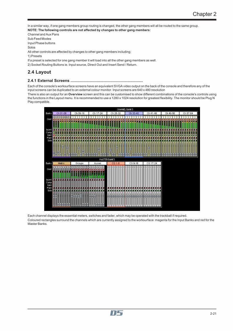
Chapter 2
2-21
In a similar way, if one gang members group routing is changed, the other gang members will all be routed to the same group.NOTE: The following controls are not affected by changes to other gang members:Channel and Aux PansSub Feed ModesInput Phase buttonsSolosAll other controls are affected by changes to other gang members including;1) PresetsIf a preset is selected for one gang member it will load into all the other gang members as well.2) Socket Routing Buttons ie. Input source, Direct Out and Insert Send / Return.
2.4 Layout2.4.1 External Screens ..................................................................Each of the console's worksurface screens have an equivalent SVGA video output on the back of the console and therefore any of theinput screens can be duplicated to an external colour monitor. Input screens are 640 x 480 resolutionThere is also an output for an Overview screen and this can be customised to show different combinations of the console's controls usingthe functions in the Layout menu. It is recommended to use a 1280 x 1024 resolution for greatest flexibility. The monitor should be Plug NPlay compatible.
Each channel displays the essential meters, switches and fader, which may be operated with the trackball if required.Coloured rectangles surround the channels which are currently assigned to the worksurface: magenta for the Input Banks and red for theMaster Banks.

Chapter 2
2-22
2.4.2 Overview Setup ....................................................................To change the appearance of the Overview screen touch the Layout button on the Master Screen and touch the Overview Setup button.
This panel allows you to select which banks appear on the screen and whether they are Large or Small format. The default view showsChannel Banks and Master Banks in small format.To show your choice of Output Banks, touch the relevant buttons in the left hand column and then touch the related Small or Largebuttons on the right.
2.4.3 Channel Banks .....................................................................The naming and assignment of the worksurface Fader Banks is controlled from the Channel Banks panel in the Layout menu on theMaster Screen.To Name a Channel Bank, touch the existing name eg Ch 1-8 and type a new one.To include the Channel Bank on the Overview Screen touch the Include button next to the relevant Bank name.To change the appearance of the Channel Banks on the Overview Screen touch the Small or Large View buttons at the bottom of thepanel.
Touch here and type toname Channel Bank
Include channelin Overview Screen
Assign Bank toWorksurface
Clear Bank fromWorksurface
Overview Screensize

Chapter 2
2-23
To Clear a Channel Bank from a worksurface Fader Bank:1) Touch the Clear Assignment button.2) Press the Fader Bank button that you wish to clear.To assign a Channel bank to one of the console worksurface Fader Banks:1) Touch the Channel Bank Assign button2) Press the relevant Fader Bank button.
21
3
2.4.4 Master Banks ........................................................................The naming and assignment of the worksurface Master Fader Banks is controlled from the Master Fader Banks panel in the Layout menuon the Master Screen.To Name a Master Fader Bank, touch the existing name eg CG 1-8 and type a new one.To include the Master Fader Bank on the Overview Screen touch the Include button next to the relevant Bank name.To change the appearance of the Master Fader Banks on the Overview Screen touch the Small or Large View buttons at the bottom ofthe panel.
Touch here and type toname Master Bank
Include Master Bankin Overview Screen
Clear Bank fromWorksurface
Overview Screensize

Chapter 2
2-24
2.4.5 Move Channels .....................................................................Touching the Move Channels button in the Layout menu opens the Move Input Channels panel which allows a single channel or a rangeof channels to be moved.
Touching a single channel allows it to be shuffled left or right with the arrows at the bottom of the panel. Both halves of a stereo linked pairare automatically selected together. Shuffling will automatically skip past stereo-linked pairs when moving the selected channels to theirnew positions.Touching two channels or a gang defines a range to be moved. The shuffle arrows now operate on this range of channels, and the doublearrows move by the number of channels in the range.Touching a third channel defines the left of the destination range and enables the Move Intervening and Swap Channels buttons. Amove or a swap cannot take place if a stereo pair would be split as a result; a warning message is displayed instead.Move Intervening means move the source range to the destination position and shuffle all channels between the source and thedestination (including all channels in the destination range) to fill the gap left by the source range.Swap Channels swaps the source and destination ranges leaving intervening channels alone. Move and Swap have the same effect ifthe source and destination ranges overlap.After a Move or a Swap the selections are cleared but the panel remains visible tor a new selection. The shuffle buttons do not clear anyselections and remain enabled as long as at least one source channel is selected.Single channels may be moved or swapped simply by touching the source channel twice when the top selection button is pressed. Any ofthe three selections can be changed by pressing the relevant button and touching a fader.
2.4.6 Copy Channels .....................................................................Touching the Copy Channels button in the Layout menu opens the Copy Input Channels panel which allows different elements ofchannel settings to be copied.
Touch faders to define the start and end of the range to be copied and then touch a third fader to define the destination for the left handside of the group. The selected group will be highlighted in yellow in the input screen.The destination channels will be overwritten and their previous settings will be deleted
ScopeWhich controller values are copied depends on the scope buttons beneath the word Include.INP = all input routing controls, including gain and signal sourceEQ = all EQ controls, plus HP and LP filtersDYN = all Gate and Compressor controls plus gate key route, and HP / LP filters in dynamicsAUX = all aux send controls

Chapter 2
2-25
FAD=channel fader positionsPAN = L/R and F/B pan or balance, Sub and Divergence levels and switchesGRP = Group routing buttons onlyChannel mutes and control group membership are always included.Direct Outputs and Insert Sends can only be fed from one channel at a time and therefore their routing is not copied. Stereo channels willbe copied as long as sufficient audio processing (unrouted channels) is available, otherwise they will appear as mono.
2.4.7 Duplicate Channel ................................................................Where Copy Channels only duplicates each of a block of channels once, the Duplicate Channel panel allows a single source channel to becopied into several destination channels, duplicating the source several times.
Touch a fader to define which channel will be duplicated and then touch two more channels to define the destination range. The sourcechannel will be duplicated into each channel in the destination range.Scope is applied in the same way as with Copy Channels (See previous section).
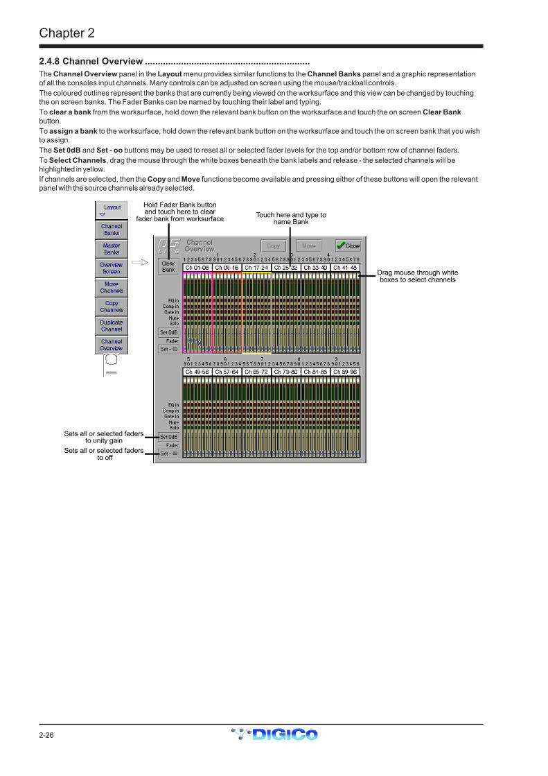
Chapter 2
2-26
2.4.8 Channel Overview ................................................................The Channel Overview panel in the Layout menu provides similar functions to the Channel Banks panel and a graphic representationof all the consoles input channels. Many controls can be adjusted on screen using the mouse/trackball controls.The coloured outlines represent the banks that are currently being viewed on the worksurface and this view can be changed by touchingthe on screen banks. The Fader Banks can be named by touching their label and typing.To clear a bank from the worksurface, hold down the relevant bank button on the worksurface and touch the on screen Clear Bankbutton.To assign a bank to the worksurface, hold down the relevant bank button on the worksurface and touch the on screen bank that you wishto assign.The Set 0dB and Set - oo buttons may be used to reset all or selected fader levels for the top and/or bottom row of channel faders.To Select Channels, drag the mouse through the white boxes beneath the bank labels and release - the selected channels will behighlighted in yellow.If channels are selected, then the Copy and Move functions become available and pressing either of these buttons will open the relevantpanel with the source channels already selected.
Include Master Bankin Overview Screen
Sets all or selected fadersto unity gain
Sets all or selected fadersto off
Touch here and type toname Bank
Hold Fader Bank buttonand touch here to clear
fader bank from worksurface
Drag mouse through whiteboxes to select channels
Chapter 3
3-1
Chapter 3Busses and Outputs

3-2
Chapter 3

Chapter 3
3-3
3.1 Busses and Outputs
3.1.1 Buss Outputs Display ..........................................................The Master, Group, Aux and Matrix busses are displayed on the Master Screen, and the buss levels are controlled by the fader banksbelow the screen:
The exact appearance of the screen depends on the console's current buss configuration, but the layout will look something like this:
Scrolling the Master ScreenIf the console configuration is using more than the 24 outputs which the screen can display, you can "scroll" the screen down the rows ofbusses using the Master Screen Scroll on the left hand side of the section
On Screen Buss Output ControlsEach buss has Mute, Solo, Insert On/Off and Limiter In/Out buttons and the screen also displays an Over light for each buss - theseare described in the next section.

3-4
Chapter 3
3.1.2 Expanding the Buss Output View ......................................In the default state shown on the previous page, the level for each buss is controlled by a single fader, whether the buss is mono, stereo orsurround.To see an expanded view of an assigned buss and access additional controls, touch the buss meter display.
Touching the expanded view of the buss meter will restore the display back to the single-fader mode.
3.2 Output and Buss ControlsOnce an output channel is expanded, you can access its controls.
Buss Control button
Buss Label
Level Trim (use fader)
Limiter In/OutLimiter Threshold (use fader)
Limiter Release (use fader)
"Over" Indicator
Output Routing
Mute
The Label, Buss Control and Routing settings apply to the whole buss, but for Stereo and Surround busses the other controls can be setindependently for each signal on the buss.

Chapter 3
3-5
3.2.1 Label ......................................................................................The Label operates in the same way as an Input Channel label - to change it, just touch the on-screen label, then type a new name on thecomputer keyboard or the On Screen Touch Keyboard.When a buss is labelled its name will appear in the input channel routing display.
3.2.2 Buss Control Button ............................................................Touching the Buss Control button displays a screen showing which channels are currently routed to the buss and offers different optionsaccording to the type of buss it is.
Group Buss Control
Connect All routes all input channels to the buss.Any fader which is being touched will be omitted from the connection process to facilitate the set up of a mix-minus feed.Clear All clears the routing of all input channels from the buss.Any fader which is being touched will be omitted from the clearing process and remain connected to the buss.To Master allows the group to be routed onto the Master Buss. Only groups whose width is the same as the Master Buss can be routed inthis way (ie. stereo groups on a stereo console; surround stems only in surround modes).When a buss is routed to the Master Mix, audio processing resources are taken from the highest numbered available input channels. Ifinsufficient channels are available a message is displayed quoting the number required.If any of the input channels routed to the group are also routed to the Master Mix, a warning is displayed.Note: The To Master button is not included in snapshots.
Auxiliary Buss Control
Switch All Pre-Mute/Pre-Fader makes the auxiliary sends for this particular buss pre-mute and pre-fader on all channels.Switch All Post-Mute/Pre-Fader makes the auxiliary sends for this particular buss post-mute and pre-fader on all channels.Switch All Post-Mute/Post-Fader makes the auxiliary sends for this particular buss post-mute and post-fader on all channels.Copy Levels from Faders makes the auxiliary send levels for this particular buss the same as the fader levels on each different channel.Set Levels OFF turns off all the auxiliary sends for this particular buss on all channels.Set Levels to 0dB makes the auxiliary send levels for this particular buss 0dB on all channels.Assign Sends To Faders transfers auxiliary send control to the channel faders for the relevant auxiliary.Assign Sends To Rotaries scrolls the input channel view to the relevant auxiliary and allows immediate rotary control of the send.Note: To activate Assign Sends to Faders/Rotaries using Solo Press see Section 4.5 - Master LCD Function Buttons.
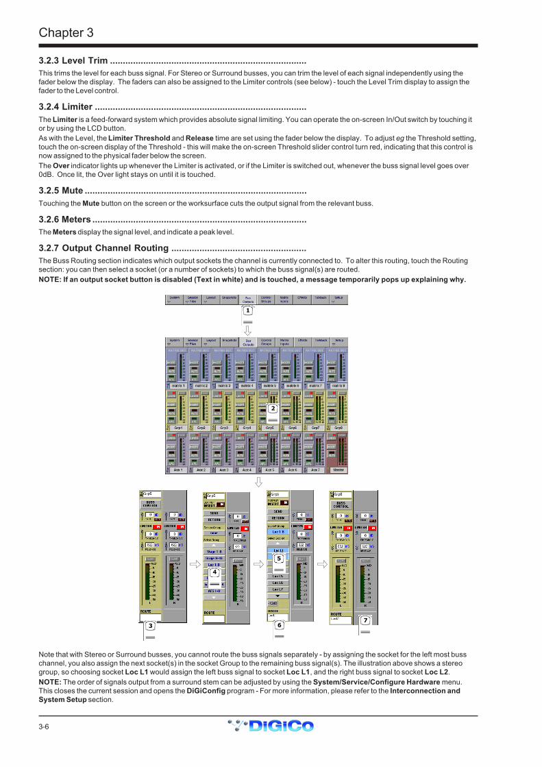
3-6
Chapter 3
3.2.3 Level Trim .............................................................................This trims the level for each buss signal. For Stereo or Surround busses, you can trim the level of each signal independently using thefader below the display. The faders can also be assigned to the Limiter controls (see below) - touch the Level Trim display to assign thefader to the Level control.
3.2.4 Limiter ...................................................................................The Limiter is a feed-forward system which provides absolute signal limiting. You can operate the on-screen In/Out switch by touching itor by using the LCD button.As with the Level, the Limiter Threshold and Release time are set using the fader below the display. To adjust eg the Threshold setting,touch the on-screen display of the Threshold - this will make the on-screen Threshold slider control turn red, indicating that this control isnow assigned to the physical fader below the screen.The Over indicator lights up whenever the Limiter is activated, or if the Limiter is switched out, whenever the buss signal level goes over0dB. Once lit, the Over light stays on until it is touched.
3.2.5 Mute .......................................................................................Touching the Mute button on the screen or the worksurface cuts the output signal from the relevant buss.
3.2.6 Meters ....................................................................................The Meters display the signal level, and indicate a peak level.
3.2.7 Output Channel Routing .....................................................The Buss Routing section indicates which output sockets the channel is currently connected to. To alter this routing, touch the Routingsection: you can then select a socket (or a number of sockets) to which the buss signal(s) are routed.NOTE: If an output socket button is disabled (Text in white) and is touched, a message temporarily pops up explaining why.
1
2
3
4
5
67
Note that with Stereo or Surround busses, you cannot route the buss signals separately - by assigning the socket for the left most busschannel, you also assign the next socket(s) in the socket Group to the remaining buss signal(s). The illustration above shows a stereogroup, so choosing socket Loc L1 would assign the left buss signal to socket Loc L1, and the right buss signal to socket Loc L2.NOTE: The order of signals output from a surround stem can be adjusted by using the System/Service/Configure Hardware menu.This closes the current session and opens the DiGiConfig program - For more information, please refer to the Interconnection andSystem Setup section.
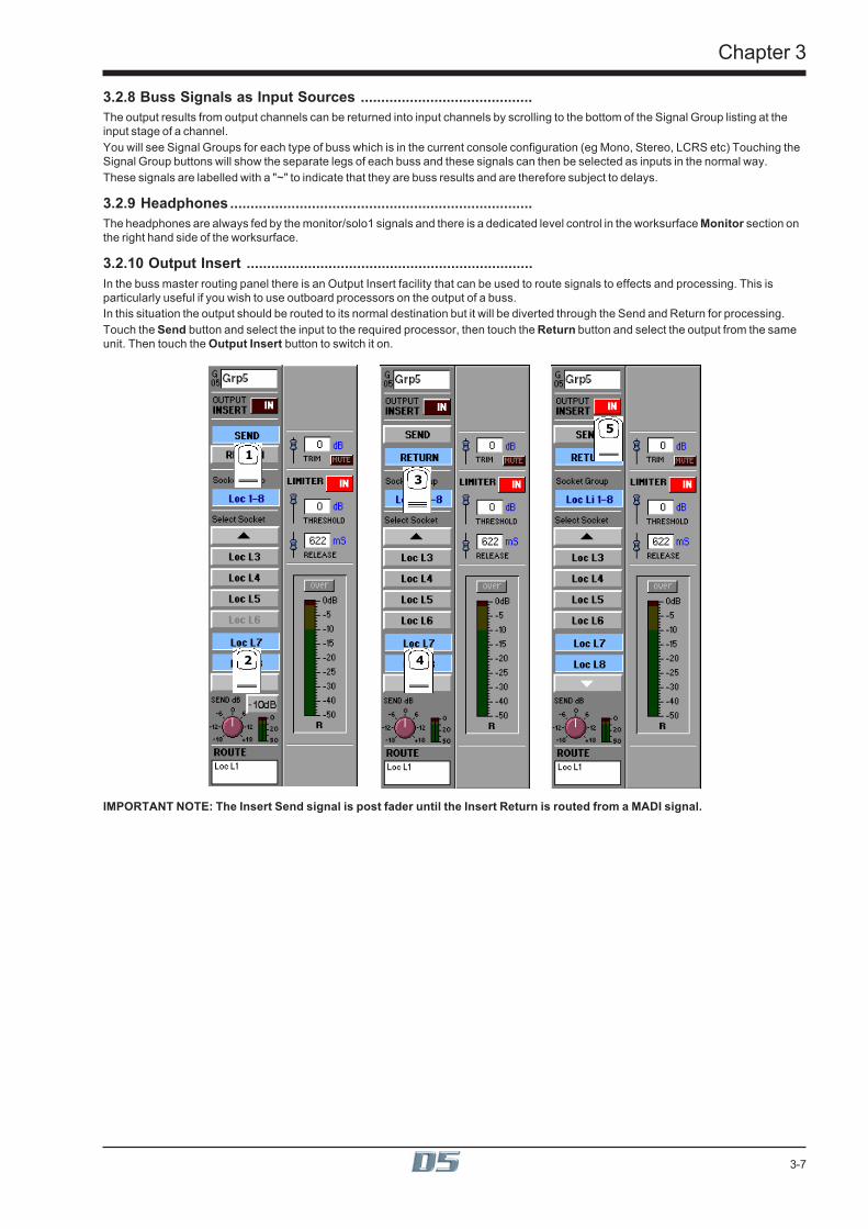
Chapter 3
3-7
3.2.8 Buss Signals as Input Sources ..........................................The output results from output channels can be returned into input channels by scrolling to the bottom of the Signal Group listing at theinput stage of a channel.You will see Signal Groups for each type of buss which is in the current console configuration (eg Mono, Stereo, LCRS etc) Touching theSignal Group buttons will show the separate legs of each buss and these signals can then be selected as inputs in the normal way.These signals are labelled with a "~" to indicate that they are buss results and are therefore subject to delays.
3.2.9 Headphones..........................................................................The headphones are always fed by the monitor/solo1 signals and there is a dedicated level control in the worksurface Monitor section onthe right hand side of the worksurface.
3.2.10 Output Insert ......................................................................In the buss master routing panel there is an Output Insert facility that can be used to route signals to effects and processing. This isparticularly useful if you wish to use outboard processors on the output of a buss.In this situation the output should be routed to its normal destination but it will be diverted through the Send and Return for processing.Touch the Send button and select the input to the required processor, then touch the Return button and select the output from the sameunit. Then touch the Output Insert button to switch it on.
1
2
3
4
5
IMPORTANT NOTE: The Insert Send signal is post fader until the Insert Return is routed from a MADI signal.

3-8
Chapter 3
3.3 The MatrixThe 38x8 way Matrix is accessed by touching the Matrix Inputs button on the Master Screen or the Matrix button on the far right of theworksurface Master Section.Inputs are selected in the same way as the input channels.Touch the on screen matrix send controls to select which ones you wish to adjust and they will become highlighted.Use the worksurface Matrix Send control and On/Off switch to adjust the settings for all highlighted sends.At the bottom of the panel there are buttons to Clear All Assignment, Load and Save Presets and Scroll buttons to view the otherinputs.
Matrix Send
Send On/Off
Open Matrix
Matrix PresetsClear All Selections Scroll Inputs
1
2

4-1
Chapter 4
Chapter 4Master Section

Chapter 4
4-2

4-3
Chapter 4
4.1 Master SectionThe Master section of the D5 console includes the output controls described in the previous chapter and the meter bridge above it:
Meter Status
Master Fader Banks
Master Screen
ScreenScroll
Mute and Interactive LCDFunction Button
Output / Control GroupFaders
Talkback
Snapshots
Monitoring
Matrix Controls
Master MuteFlip Master Fader Banks
Master Fader
Mute and Interactive LCDFunction Button
Master Fader Banks
Output / Control GroupFaders
4.1.1 The Master Screen ...............................................................Master Screen Status DisplayThe master screen displays information on the current session, mode, timecode and sync at the top left. The system date and time aredisplayed on the right Further system information can be found in the Diagnostics Panel (System Menu).

Chapter 4
4-4
4.1.2 The Menu Buttons ...............................................................System MenuThis menu, displayed by touching the System button, contains additional buttons which display system information.
System Shut Down ButtonThis command should be used to shut down the console in normal operation.
Quit To Windows CommandIn the Service menu, this button will close the D5 program but will remain in a Windows environment. It is unlikely that the user will needthis option in normal operation.
System OptionsTo adjust the level of lighting on the console use the up down arrows next to the value boxes for White Light Illumination Brightness,Screen Brightness or Surface Label Display Brightness
Use On Screen Touch Keyboard activates a touch sensitive keyboard which will automatically appear on screen when any label button(Channel, name, control group etc) is pressed.While editing numeric-only data such as timecode, a small numeric keypad will appear.This is intended as an alternative to using the computer keyboard itself.
Show System Status Indicators activates on screen information concerning the system. This will appear in the bottom right hand cornerof the Master Screen.Show aux and fader dB Pop-up Readouts activates yellow boxes which pop up showing the Auxiliary send and fader dB displays.Display System Alerts activates on screen information to warn the user of any potential problem with the system.Round to whole dBs switches any dB readouts to whole dB measurements instead of decimal places.If Save Startup Session On Exit is pressed the console automatically saves a file named startup.ses in the D5 directory when it isclosed down. The next time the console is started, this session will be loaded automatically.If you wish to always have the same session loaded on startup you can switch this function off and save your own file with the namestartup.ses in the D5 directory. This will only be overwritten if the function is switched on again.
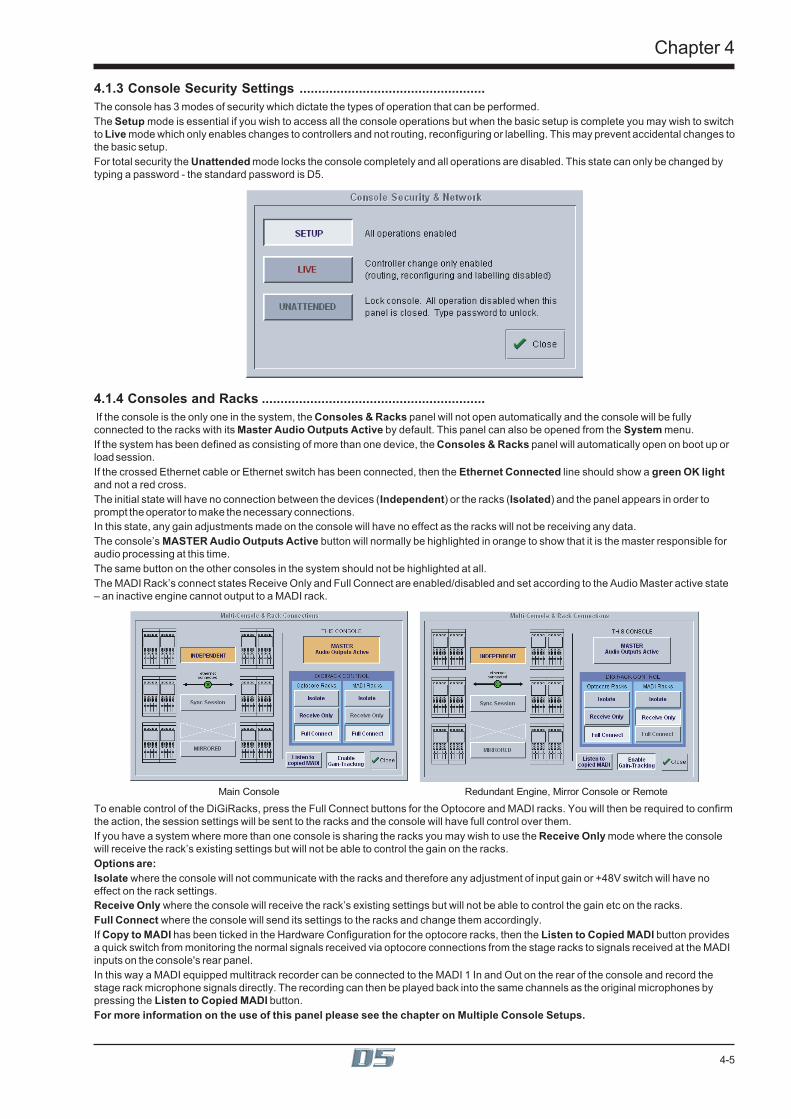
4-5
Chapter 4
4.1.3 Console Security Settings ..................................................The console has 3 modes of security which dictate the types of operation that can be performed.The Setup mode is essential if you wish to access all the console operations but when the basic setup is complete you may wish to switchto Live mode which only enables changes to controllers and not routing, reconfiguring or labelling. This may prevent accidental changes tothe basic setup.For total security the Unattended mode locks the console completely and all operations are disabled. This state can only be changed bytyping a password - the standard password is D5.
4.1.4 Consoles and Racks ............................................................ If the console is the only one in the system, the Consoles & Racks panel will not open automatically and the console will be fullyconnected to the racks with its Master Audio Outputs Active by default. This panel can also be opened from the System menu.If the system has been defined as consisting of more than one device, the Consoles & Racks panel will automatically open on boot up orload session.If the crossed Ethernet cable or Ethernet switch has been connected, then the Ethernet Connected line should show a green OK lightand not a red cross.The initial state will have no connection between the devices (Independent) or the racks (Isolated) and the panel appears in order toprompt the operator to make the necessary connections.In this state, any gain adjustments made on the console will have no effect as the racks will not be receiving any data.The console’s MASTER Audio Outputs Active button will normally be highlighted in orange to show that it is the master responsible foraudio processing at this time.The same button on the other consoles in the system should not be highlighted at all.The MADI Rack’s connect states Receive Only and Full Connect are enabled/disabled and set according to the Audio Master active state– an inactive engine cannot output to a MADI rack.
Main Console Redundant Engine, Mirror Console or Remote
To enable control of the DiGiRacks, press the Full Connect buttons for the Optocore and MADI racks. You will then be required to confirmthe action, the session settings will be sent to the racks and the console will have full control over them.If you have a system where more than one console is sharing the racks you may wish to use the Receive Only mode where the consolewill receive the rack’s existing settings but will not be able to control the gain on the racks.Options are:Isolate where the console will not communicate with the racks and therefore any adjustment of input gain or +48V switch will have noeffect on the rack settings.Receive Only where the console will receive the rack’s existing settings but will not be able to control the gain etc on the racks.Full Connect where the console will send its settings to the racks and change them accordingly.If Copy to MADI has been ticked in the Hardware Configuration for the optocore racks, then the Listen to Copied MADI button providesa quick switch from monitoring the normal signals received via optocore connections from the stage racks to signals received at the MADIinputs on the console's rear panel.In this way a MADI equipped multitrack recorder can be connected to the MADI 1 In and Out on the rear of the console and record thestage rack microphone signals directly. The recording can then be played back into the same channels as the original microphones bypressing the Listen to Copied MADI button.For more information on the use of this panel please see the chapter on Multiple Console Setups.

Chapter 4
4-6
4.2 Configuring the ConsoleAs a digital console, the D5 is highly configurable, allowing a wide range of different bussing formats and channel configurations. Thissection describes how to use the command buttons on the Master Screen to Configure, store and recall sessions.A Session file contains the following information:• The console configuration.
• The Snapshots.
A Session file therefore represents a complete "snapshot" of the console, and is the simplest way to store and recall a complete systemsetup.
4.2.1 Session Files Menu..............................................................All of the configuration and file management functions are handled in the Session Files Menu which is accessed by touching the button onthe Master Screen.
4.2.2 The New Session Panel .......................................................The Main Buss Mode defines the format of the Main buss as Stereo, LCR(S) or 5.1 Surround. This also affects the options for selectingthe Group and Aux buss formats: if the Main buss is stereo, the other busses cannot use the Surround formats, and if the main buss isSurround format, the other busses cannot use a different Surround format (although they can be stereo).The Output Groups and Aux Outputs settings allow you to define the format and number of the Aux and Group busses.The total amount of busses cannot exceed 36 in Stereo mode (extra busses are reserved for the Main and Solo/AFL functions).
Note: The total number of busses available will be affected by the choice of Main Buss Mode selected.For example, if you wish to use AFL within a 5.1 Surround console configuration, an extra 6 busses will have to be reserved for thatpurpose.
4.2.3 Clearing Settings .................................................................When you start a new session all current settings will be inherited by default but Snapshots will be cleared.The buttons at the bottom of the New Session panel allow you to clear settings according to your own requirements. When the buttonsare pressed, the relevant settings will be cleared. If you are simply adjusting the buss configuration of an existing console you are unlikelyto wish to clear all of your current settings.Note: Clearing Output Processors is linked to the Aux Outputs button.You may also choose to Set all Input Direct Sends to Pre-Mute/Pre-Fader, Post-Mute/Pre-Fader or Post-Mute/Post-Fader for the newsession. Remember that when all settings are cleared, any labelling or routing which you have done will be lost.

4-7
Chapter 4
4.2.4 The Load Session Button ...................................................Touching this button will open the following panel.
1
2
3
4
5
This panel shows the contents of your drives and folders, listing any saved sessions with a note of the console configurations on the righthand side of the screen. These include the removable drive that can be plugged into the USB Data Port on the meter bridge.Simply select the drive you require in the bottom left corner and then open a folder from the scrolling list next to it by touching it. You canthen touch a specific session file to highlight it and touch the Load button to open the session.Sessions can also be renamed or deleted in this panel using the Rename File or Delete File buttons in the same way.The smaller New Project, Rename, and Delete buttons all refer to the folder listing and also appear in the Save As New File PanelThe Set Backup Files button is only relevant if your system is connected to a NetTracs server which is used in multiple console environ-ments to store and backup files.
New ProjectCreates a new folder with the default name Proj001. You can then rename this as required.
RenameTouch this button and then touch the folder name that you wish to change. This will then be highlighted and you may type a new name.
DeleteTouch this button and then touch the folder name that you wish to delete. You will then be asked to confirm the deletion request.

Chapter 4
4-8
4.2.5 The Save As New File Button .............................................Touching this button will open the following panel.
This panel allows sessions to be saved as new files under new names. Select your drive and folder by touching in the boxes in the bottomleft corner, then touch and type a new file name (with a maximum of 8 letters and no punctuation) in the box on the top left. You may alsospecify a session title which can be a different name to the file itself and may therefore be longer and more descriptive. Then touch theSave button to complete the process.NB: If you touch a session name on the existing list, this name will automatically be selected as the new file name andtouching Save will overwrite the old file.
4.2.6 The Save Session Button ....................................................This button which is found above the Save As New File button will save the existing session in the same location and under the same filename as it was previously saved or loaded from. It therefore serves as a "Quick Save" option to update an existing session.Remember that this function will overwrite your last saved version.If you wish to save the session under a new name use the Sessions menu button and select Save As New File (See above).
4.2.7 USB Data Port .......................................................................The console ie equipped with a Data Port which is designed for use with a key-ring style data card. To use this facility, insert the card intothe USB Data Port and it will be recognised as an external drive. It will then appear in the Load and Save panels and can be used forstorage and retrieval of sessions and presets.
4.2.8 Managing Presets ................................................................Presets (Channel, EQ and Dynamics) can be loaded and saved in any file ending with .PRE.Under the Sessions menu, touch the Load Presets button and the following panel will appear:
This panel shows the contents of your drives and folders, listing any saved presets.Simply select the drive you require in the bottom left corner and then open a folder from the scrolling list next to it by touching it. You canthen touch a specific preset file to highlight it and touch the Load button.If you wish to keep your existing presets and add the contents of a saved presets file to them, touch the Merge button.Presets can also be renamed or deleted in this panel using the Rename File or Delete File buttons in the same way.The smaller New Folder, Rename, and Delete buttons all refer to the folder listing and also appear in the Save Presets panel.To save a Preset file touch the Save Presets button and the following panel will appear:

4-9
Chapter 4
Select a drive and folder in the bottom left hand corner of the panel, type a new name in the New Filename box and press the Savebutton.NOTE: The current presets file is always saved automatically when the console is shut down
4.2.9 Monitoring ............................................................................The Monitoring panel can be found under the Setup Menu in the Master Screen and some of the controls can be accessed on the righthand side of the Master worksurface.It may be accessed at any time to change the monitoring setup.
Solo Modes
Assign Solo 2 Levelto Master faderClear All Solos
Monitor Master BussWhen No Solo On
Route Solo 1 To Output Route Solo 2 To Output
Solo 1 Controls
Set Solo 1 Mono Set Solo 2 Mono
Solo 2 Controls
Solo Safe

Chapter 4
4-10
There are two solo busses and each console solo button can be independently assigned to use Solo 1 or Solo 2. Output solos may use atotal of 16 inputs to each solo buss.Therefore, if the console was being used for stage monitors, the first solo buss could feed an "in ear" monitor and the second solo busscould feed a wedge.To use Solo 2 there must be sufficient busses available (at least two) and if Solo 2 does not appear on the panel a new session should becreated to make these busses available.The dedicated worksurface buttons control the relevant Monitor/Solo 1 functions and the Solo 2 level and trim may be controlled bytouching the on screen control and using the Matrix rotary control on the worksurface.To Select Solo 1 or 2 for a Buss or Channel1) Press the Master or Channel LCD Function button for the relevant bank or channel.2) Press the Solo 1 OR 2 button - All Solos are set to Solo 1 by default.3) Press the LCD button for the Buss or Channel that you wish to switch to Solo 2 (It will change colour and Solo 2 will be indicated).4) Press the Master or Channel LCD Function button to exit Solo 1 or 2 mode.5) Press the Solo function button to return to the standard view and you will see Solo 2 indicated on the button.
Aux 01
A01 [0]LCD
FUNCTION
SOLO SAFESOLO
ASSIGNSAUX>FAD
Aux 02
A02 [0]
Aux 03
A03 [0]
Aux 04
A04 [0]
Aux 05
A05 [0]
Aux 06
A06 [0]
Aux 07
A07 [0]
Aux 08
A08 [0]
LCDFUNCTION
1
BUILDBANK
2
A01 [0]LCD
FUNCTION A02 [0] A03 [0] A04 [0] A05 [0] A06 [0] A07 [0] A08 [0]
SOLO SAFESOLO
ASSIGNSAUX>FAD
LCDFUNCTION
BUILDBANK
SOLOASSIGNSAUX>ROT
SOLOASSIGNSAUX>ROT
AFL AFL AFL AFL AFL AFL AFL AFL
ASSIGNFADERS
UNASSIGNFADERS
SOLO1 OR 2
ASSIGNFADERS
UNASSIGNFADERS
SOLO1 OR 2
AFL2 AFL AFL AFL AFL AFL AFL AFL
Aux 01 Aux 02 Aux 03 Aux 04 Aux 05 Aux 06 Aux 07 Aux 08
A01 [0]LCD
FUNCTION A02 [0] A03 [0] A04 [0] A05 [0] A06 [0] A07 [0] A08 [0]
SOLO 1 2<
Aux 01 Aux 02 Aux 03 Aux 04 Aux 05 Aux 06 Aux 07 Aux 08
SOLO 1<2 SOLO 1<2 SOLO 1<2 SOLO 1<2 SOLO 1<2 SOLO 1<2 SOLO 1<2
34
5
PFL (Default mode with nothing else selected)Mono pre-fader listen mode which only uses one reserved buss.AFLMonitoring the signal at post-fader level with full stereo or surround panning which uses the same number of busses as the Master buss.SIP (Destructive Solo In Place)This function leaves the soloed signal routed to its current destination and mutes all non-soloedsignals. To hear the soloed signal(s), the relevant buss(es) should be monitored.Note: This function can only be switched on by holding down the SIP button for 2 seconds.SingleSingle mode means that only one channel can be soloed at a time. If single is not selected, any number of channels can be soloedsimultaneously.Monitor/Solo 1 and Solo 2 OutputsThis allows you to select dedicated output sockets for the Monitor/Solo 1 and/or Solo 2 signals. Touch the required Output Signal Groupbutton and then the first output (left) that you require from that group. The second output (right) will be automatically selected. A button atthe bottom of the panel will switch the solo to Mono.Monitor DelayThe monitor signal can be delayed by up to 160ms using the on screen rotary control. This control may also be adjusted by touching it onscreen and using the worksurface Matrix rotary control.Monitor MasterIf this button is pressed, the master buss will be monitored when no solos are on.Solo 2 Assign To Master FaderIf this button is pressed, Solo 2's Level and Mute controls can be adjusted using the Master Fader and Mute.

4-11
Chapter 4
Monitor MuteTouch the Mute button to cut the monitor signal.Solo ClearPressing the Solo Clear button will ensure that there are no solos engaged anywhere on the console.Solo Trim LevelThe Solo Level may be adjusted by altering the dB value in the Trim Level box. If the worksurface "Solo Trim" control is adjusted, thispanel will automatically appear and the Trim Level value will change to reflect any adjustment.Solo SafeSolo safe may be used in any solo mode.If the Solo Safe button is pressed, channels that appear on the list will be soloed automatically whenever any other solo is pressed.To add channels to the list, press the Touch Faders to Select button and touch the required faders. When the Solo Safe button isswitched off, the list is not affected and the Solo Safe function is disabled. The contents of the list are saved in the session files.Note: If one of the channels on the list is soloed manually the other channels are not automatically soloed with it.
4.2.10 Master Section Meters .......................................................
Successive presses of the Meter Button in the top right hand corner of the worksurface will toggle through three metering options, theseare:Meter Master Buss (Default)Meter MonitorsThe meters will show the selected type of monitor signal. (Master buss or PFL/AFL/Destructive SIP)Meter Selected BussesThe meters in the console's Master section can be assigned to any console buss.To assign Group or Aux busses to the Master meters, press and hold down the Meter Button in the top right hand corner of theworksurface and touch up to eight buss displays on the Master screen one after the other. Release the button when all the requiredbusses are selected.Upper BankThe meters follow the currently assigned upper master fader bank. Unlike the other modes, the fourth displays stereo groups on one meterwith twin peaks, just like input channels. Surround groups only meter left & right signals in this mode.Note: If input channels have been assigned to master banks, the metered signal is pre-fader.
4.2.11 Meter Bridge Options ........................................................Touching the Meter Bridge button in the Setup menu allows you to choose between two options:The default setting is Inputs & Outputs where the Input Section meters show the corresponding Input Channel signal and the MasterSection Meters show the outputs.The other option is All Outputs where the output signals are shown consecutively across the entire Meter Bridge.In this mode, holding the Meter Button and touching a row of on-screen outputs will determine which outputs are assigned to the meterson the first Input Section.
4.2.12 Meter Ballistics ...................................................................Touching the Meter Ballistics button in the Setup menu opens the following panel:
This allows ballistics to be altered for all meters on the bridge and screens using the up/down arrows on the panel.VU Default sets Attack and Release to 300ms.PPM Default sets Attack to 41ms and Release to 416ms which are the engine defaults.Peak Hold time can be adjusted to a value between 10 and 9999ms

Chapter 4
4-12
4.2.13 Restart and Recovery ........................................................When changes are made to a session it is important to save the session regularly as the recovery process uses the last savedsession.In the unlikely event of a console software crash, an abnormal shutdown, hardware or power failure, D5 will recover the latest sessionautomatically and it can be rebooted without losing audio.If there is any problem with this process, holding the keyboard Shift Key during the reloading of D5 software will open the following panel:IMPORTANT NOTE: The easiest method of doing this is to Quit To Windows and then reload D5 software from there.If you are holding the SHIFT Key when Windows is reloading, the D5 Surfaces program and D5 software itself will not load automatically.If this situation occurs be sure to restart Surfaces.exe from the Windows Start menu before loading D5 software.
This allows the options of:1) Rebooting the audio engine or worksurface.2) Recovering the last session from NVRAM and last saved session file.2) Loading from the last startup session file.3) Not loading any file and creating a default stereo console.
4.3 TalkbackThe console includes a built-in talkback microphone socket situated in the top right hand corner of the worksurface, and there is an inputsocket provided on the rear panel for a 2nd remote talkback microphone. There are two Talkback channels, A and B, and both can beactivated by buttons on the worksurface in conjunction with three Talback Feed Presets, labelled a,b and c. Both channels are controlledby a level control on the worksurface.

4-13
Chapter 4
4.3.1 Talkback Configuration Button ..........................................The two talkback channels can be mixed independently onto any buss using the Talkback Setup panel, which is displayed on the Masterscreen when the on-screen Talkback button is touched.
When you first touch the on-screen Talkback button, only the bottom section of the panel is displayed - push the Talkback Setup button todisplay the full mixer panel.
4.3.2 Talkback Mic Setup ..............................................................Talkback channels A and B can be controlled separately, by touching the relevant button at the bottom left of the Talkback configurationpanel.
Talkback channels A and B can be sourced from any input signal, the Local (Top) mic, the Rear Mic, Tone or Noise using the buttons atthe top of the Channel.Both channels could be sourced from the same mic but each one could route to different output destinations.Each channel has a high-pass filter, a compressor with variable threshold, and a control for the Dim level which is applied to the monitorsignal when the Talk switch is pushed. These can all be adjusted by touching them on-screen, then using the fader below the display.Below these controls are buttons which configure the talkback switch. The switches can be latching or momentary, and you can alsochoose to disable either channel altogether.The worksurface Talkback buttons A, B, and C may be used to activate either Talkback Channel by pressing the required combination ofthe On With buttons.
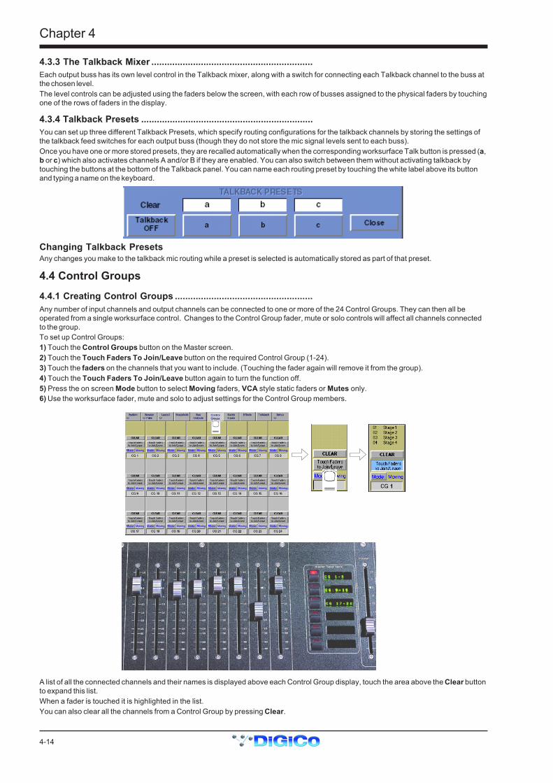
Chapter 4
4-14
4.3.3 The Talkback Mixer ..............................................................Each output buss has its own level control in the Talkback mixer, along with a switch for connecting each Talkback channel to the buss atthe chosen level.The level controls can be adjusted using the faders below the screen, with each row of busses assigned to the physical faders by touchingone of the rows of faders in the display.
4.3.4 Talkback Presets ..................................................................You can set up three different Talkback Presets, which specify routing configurations for the talkback channels by storing the settings ofthe talkback feed switches for each output buss (though they do not store the mic signal levels sent to each buss).Once you have one or more stored presets, they are recalled automatically when the corresponding worksurface Talk button is pressed (a,b or c) which also activates channels A and/or B if they are enabled. You can also switch between them without activating talkback bytouching the buttons at the bottom of the Talkback panel. You can name each routing preset by touching the white label above its buttonand typing a name on the keyboard.
Changing Talkback PresetsAny changes you make to the talkback mic routing while a preset is selected is automatically stored as part of that preset.
4.4 Control Groups4.4.1 Creating Control Groups .....................................................Any number of input channels and output channels can be connected to one or more of the 24 Control Groups. They can then all beoperated from a single worksurface control. Changes to the Control Group fader, mute or solo controls will affect all channels connectedto the group.To set up Control Groups:1) Touch the Control Groups button on the Master screen.2) Touch the Touch Faders To Join/Leave button on the required Control Group (1-24).3) Touch the faders on the channels that you want to include. (Touching the fader again will remove it from the group).4) Touch the Touch Faders To Join/Leave button again to turn the function off.5) Press the on screen Mode button to select Moving faders, VCA style static faders or Mutes only.6) Use the worksurface fader, mute and solo to adjust settings for the Control Group members.
A list of all the connected channels and their names is displayed above each Control Group display, touch the area above the Clear buttonto expand this list.When a fader is touched it is highlighted in the list.You can also clear all the channels from a Control Group by pressing Clear.

4-15
Chapter 4
When a channel is a member of a Control Group, its own controls can still be adjusted independently of the other Group members.Adjustments to fader levels are transmitted to the Group members as dB changes, so that a level increase of 2dB on the Group fader willincrease all the member levels by 2dB, irrespective of the relative levels of the individual channel faders.
4.4.2 Naming Control Groups ......................................................Like inputs or busses, Control Groups can be named by touching the name display on the screen (default CG1, CG2 etc), and typing anew name on the console keyboard.
4.4.3 Mode Option .........................................................................Successive presses of the Mode button above the control group’s label allows the control group to function in one of three different ways:Moving - The default mode where the input channel faders move to reflect any adjustment made with the Control Group fader.VCA - The Control Group fader controls the level of an input channel without moving the channel’s fader.Mutes - Only Input Channel Mutes are affected by the Control Group, not faders.
4.5 Master LCD Function ButtonsPressing the Master LCD Function button on the left hand side of the Master Section allows you to select the function that the individualMaster LCD Buttons are currently assigned to.
To Show FunctionsPress the Master LCD Function button.
Grp 01
G01 [0]LCD
FUNCTION
SOLO SAFEASSIGNFADERS
SOLOASSIGNSAUX>ROT
SOLOASSIGNSAUX>FAD
Grp 02
G02 [0]
Grp 03
G03 [0]
Grp 04
G04 [0]
Grp 05
G05 [0]
Grp 06
G06 [0]
Grp 07
G07 [0]
AFL AFL AFL AFL AFL AFL AFL AFL
Grp 08
G08 [0]
LCDFUNCTION
1
UNASSIGNFADERS
BUILDBANK
SOLO1 OR 2
To Make Masters Safe From All SnapshotsThe Safe function makes selected Group, Aux, Matrix and Control Group Master Faders safe from all Snapshots.1) Press the Master LCD Function button for the relevant bank.2) Press the Safe button.3) Press the Master LCD buttons for the Masters that should be Safe (they will turn red and a tick will appear).4) Press the Master LCD Function button to exit Safe mode.5) Press the Solo function button to return to the standard view.
Grp 01
G01 [0]LCD
FUNCTION
SOLO SAFEASSIGNFADERS
SOLOASSIGNSAUX>ROT
SOLOASSIGNSAUX>FAD
Grp 02
G02 [0]
Grp 03
G03 [0]
Grp 04
G04 [0]
Grp 05
G05 [0]
Grp 06
G06 [0]
Grp 07
G07 [0]
Grp 08
G08 [0]
LCDFUNCTION
1
UNASSIGNFADERS
BUILDBANK
2
SAFE
Grp 01
G01 [0]
SAFE
Grp 02
G02 [0]
SAFE
Grp 03
G03 [0]
SAFE
Grp 04
G04 [0]
SAFE
Grp 05
G05 [0]
SAFE
Grp 06
G06 [0]
SAFE
Grp 07
G07 [0]
SAFE
Grp 08
G08 [0]LCD
FUNCTION
34
SOLO SAFESOLO
ASSIGNSAUX>ROT
SOLOASSIGNSAUX>FAD
LCDFUNCTION
BUILDBANK
5
Grp 01
G01 [0]LCD
FUNCTION
Grp 02
G02 [0]
Grp 03
G03 [0]
Grp 04
G04 [0]
Grp 05
G05 [0]
Grp 06
G06 [0]
Grp 07
G07 [0]
Grp 08
G08 [0]
AFL AFL AFL AFL AFL AFL AFL AFL
SOLO1 OR 2
ASSIGNFADERS
UNASSIGNFADERS
SOLO1 OR 2
AFL AFL AFL AFL AFL AFL AFL AFL

Chapter 4
4-16
Auxiliary sends can be controlled by the console's channel faders or rotaries in several different ways.There are Assign Sends To Faders and Assign Sends To Rotaries buttons in the Auxiliary Buss Control panel (See Section 3.2.2 -Buss Control Button) which activate these functions but for faster access there are options to activate them by a Solo Press on theAuxiliary Masters. When this function is activated, the third rotary in the input channel serves as a stereo aux pan.To switch these functions on or off:Solo Assigns Aux To Faders1) Press the Master LCD Function button.2) Press the Solo Assigns Aux > Fad button (a tick will appear in the box).3) Press the Solo function button to return to the standard view.
Grp 01
G01 [0]LCD
FUNCTION
SOLO SAFESOLO
ASSIGNSAUX>ROT
SOLOASSIGNSAUX>FAD
Grp 02
G02 [0]
Grp 03
G03 [0]
Grp 04
G04 [0]
Grp 05
G05 [0]
Grp 06
G06 [0]
Grp 07
G07 [0]
Grp 08
G08 [0]
LCDFUNCTION
1
BUILDBANK
2
Grp 01
G01 [0]LCD
FUNCTIONGrp 02
G02 [0]
Grp 03
G03 [0]
Grp 04
G04 [0]
Grp 05
G05 [0]
Grp 06
G06 [0]
Grp 07
G07 [0]
Grp 08
G08 [0]
SOLO SAFESOLO
ASSIGNSAUX>ROT
SOLOASSIGNSAUX>FAD
LCDFUNCTION
BUILDBANK
3
AFL AFL AFL AFL AFL AFL AFL AFL
ASSIGNFADERS
UNASSIGNFADERS
SOLO1 OR 2
AFL AFL AFL AFL AFL AFL AFL AFL
ASSIGNFADERS
UNASSIGNFADERS
SOLO1 OR 2
Solo Assigns Aux To RotariesWhen this function is activated and an Auxiliary Master Solo button is pressed, the Input Channel screen will automatically scroll to therelevant auxiliary and allow instant control of the send.1) Press the Master LCD Function button.2) Press the Solo Assigns Aux > Rot button (a tick will appear in the box).3) Press the Solo function button to return to the standard view.
Grp 01
G01 [0]LCD
FUNCTION
SOLO SAFESOLO
ASSIGNSAUX>FAD
Grp 02
G02 [0]
Grp 03
G03 [0]
Grp 04
G04 [0]
Grp 05
G05 [0]
Grp 06
G06 [0]
Grp 07
G07 [0]
Grp 08
G08 [0]
LCDFUNCTION
1
BUILDBANK
2
Grp 01
G01 [0]LCD
FUNCTIONGrp 02
G02 [0]
Grp 03
G03 [0]
Grp 04
G04 [0]
Grp 05
G05 [0]
Grp 06
G06 [0]
Grp 07
G07 [0]
Grp 08
G08 [0]
SOLO SAFESOLO
ASSIGNSAUX>FAD
LCDFUNCTION
BUILDBANK
3
SOLOASSIGNSAUX>ROT
SOLOASSIGNSAUX>ROT
AFL AFL AFL AFL AFL AFL AFL AFL
ASSIGNFADERS
UNASSIGNFADERS
SOLO1 OR 2
ASSIGNFADERS
UNASSIGNFADERS
SOLO1 OR 2
AFL AFL AFL AFL AFL AFL AFL AFL

4-17
Chapter 4
The contents of a Master Fader Bank can be customised at any time by adding or removing faders from it.To Assign Faders To Banks1) Press the Master LCD Function button for the relevant bank.2) Press the Assign Faders button.3) Press the Master LCD button for the Master fader that you wish to use.4) Touch the on screen meter for the Buss that you wish to Assign or touch an Input Channel screen or Control Group display. Ifseveral LCD Assign buttons are pressed, they will be filled from left to right starting with the channel that is touched.5) Press the Master LCD Function button to exit Assign Faders mode.6) Press the Solo function button to return to the standard view.
Grp 01
G01 [0]LCD
FUNCTION
SOLO SAFESOLO
ASSIGNSAUX>FAD
Grp 02
G02 [0]
Grp 03
G03 [0]
Grp 04
G04 [0]
Grp 05
G05 [0]
Grp 06
G06 [0]
Grp 07
G07 [0]
Grp 08
G08 [0]
LCDFUNCTION
1
BUILDBANK
2
ASSIGN ASSIGN
Grp 01
G01 [0]Grp 02
G02 [0]
Grp 03
G03 [0]
Grp 04
G04 [0]
Grp 05
G05 [0]
Grp 06
G06 [0]
Grp 07
G07 [0]
Grp 08
G08 [0]LCDFUNCTION
3
Grp 09
G09 [0]LCD
FUNCTIONGrp 02
G02 [0]
Grp 03
G03 [0]
Grp 04
G04 [0]
Grp 05
G05 [0]
Grp 06
G06 [0]
Grp 07
G07 [0]
Grp 08
G08 [0]
ASSIGN ASSIGN ASSIGN ASSIGN ASSIGN ASSIGN ASSIGN ASSIGN
ASSIGN ASSIGN
Grp 02
G02 [0]
Grp 03
G03 [0]
Grp 04
G04 [0]
Grp 05
G05 [0]
Grp 06
G06 [0]
Grp 07
G07 [0]
Grp 08
G08 [0]
ASSIGN ASSIGN ASSIGN ASSIGN ASSIGN ASSIGN ASSIGN
TOUCHSCREENto assign
LCDFUNCTION
ASSIGN ASSIGN
Grp 02
G02 [0]
Grp 03
G03 [0]
Grp 04
G04 [0]
Grp 05
G05 [0]
Grp 06
G06 [0]
Grp 07
G07 [0]
Grp 08
G08 [0]
ASSIGN ASSIGN ASSIGN ASSIGN ASSIGN ASSIGN ASSIGN
Grp 09
G09 [0]
ASSIGN5
4
LCDFUNCTION
SOLO SAFE
LCDFUNCTION
6
AFL AFL AFL AFL AFL AFL AFL AFL
AFL AFL AFL AFL AFL AFL AFL AFL
ASSIGNFADERS
UNASSIGNFADERS
SOLO1 OR 2
SOLOASSIGNSAUX>ROT
SOLOASSIGNSAUX>FAD
BUILDBANK
ASSIGNFADERS
UNASSIGNFADERS
SOLO1 OR 2
SOLOASSIGNSAUX>ROT

Chapter 4
4-18
To Unassign Faders From Banks1) Press the Master LCD Function button for the relevant bank.2) Press the Unassign Faders button.3) Press the Master LCD buttons for the fader(s) that you wish to Unassign.4) Press the Master LCD Function button to exit Unassign Faders mode.5) Press the Solo function button to return to the standard view.
Grp 01
G01 [0]LCD
FUNCTION
SOLO SAFE
Grp 02
G02 [0]
Grp 03
G03 [0]
Grp 04
G04 [0]
Grp 05
G05 [0]
Grp 06
G06 [0]
Grp 07
G07 [0]
Grp 08
G08 [0]
LCDFUNCTION
1
2
ASSIGN ASSIGN
Grp 01
G01 [0]Grp 02
G02 [0]
Grp 03
G03 [0]
Grp 04
G04 [0]
Grp 05
G05 [0]
Grp 06
G06 [0]
Grp 07
G07 [0]
Grp 08
G08 [0]LCDFUNCTION
3
LCDFUNCTION
Grp 02
G02 [0]
Grp 03
G03 [0]
Grp 04
G04 [0]
Grp 05
G05 [0]
Grp 06
G06 [0]
Grp 07
G07 [0]
Grp 08
G08 [0]
UNASSIGN UNASSIGN UNASSIGN UNASSIGN UNASSIGN UNASSIGN UNASSIGN UNASSIGN
ASSIGN ASSIGN
Grp 02
G02 [0]
Grp 03
G03 [0]
Grp 04
G04 [0]
Grp 05
G05 [0]
Grp 06
G06 [0]
Grp 07
G07 [0]
Grp 08
G08 [0]
UNASSIGN UNASSIGN UNASSIGN UNASSIGN UNASSIGN UNASSIGN UNASSIGN
LCDFUNCTION
4
SOLO SAFE
LCDFUNCTION
5
AFL AFL AFL AFL AFL AFL AFL AFL
SOLOASSIGNSAUX>FAD
BUILDBANK
ASSIGNFADERS
UNASSIGNFADERS
SOLO1 OR 2
SOLOASSIGNSAUX>ROT
SOLOASSIGNSAUX>FAD
BUILDBANK
ASSIGNFADERS
UNASSIGNFADERS
SOLO1 OR 2
SOLOASSIGNSAUX>ROT
AFL AFL AFL AFL AFL AFL AFL
Master Fader Banks can also be built from scratch in the following way:To Build A Bank1) Press the Master Fader Bank button for the bank that you wish to build.2) Press the Master LCD Function button for the relevant bank.3) Press the Build Bank button.
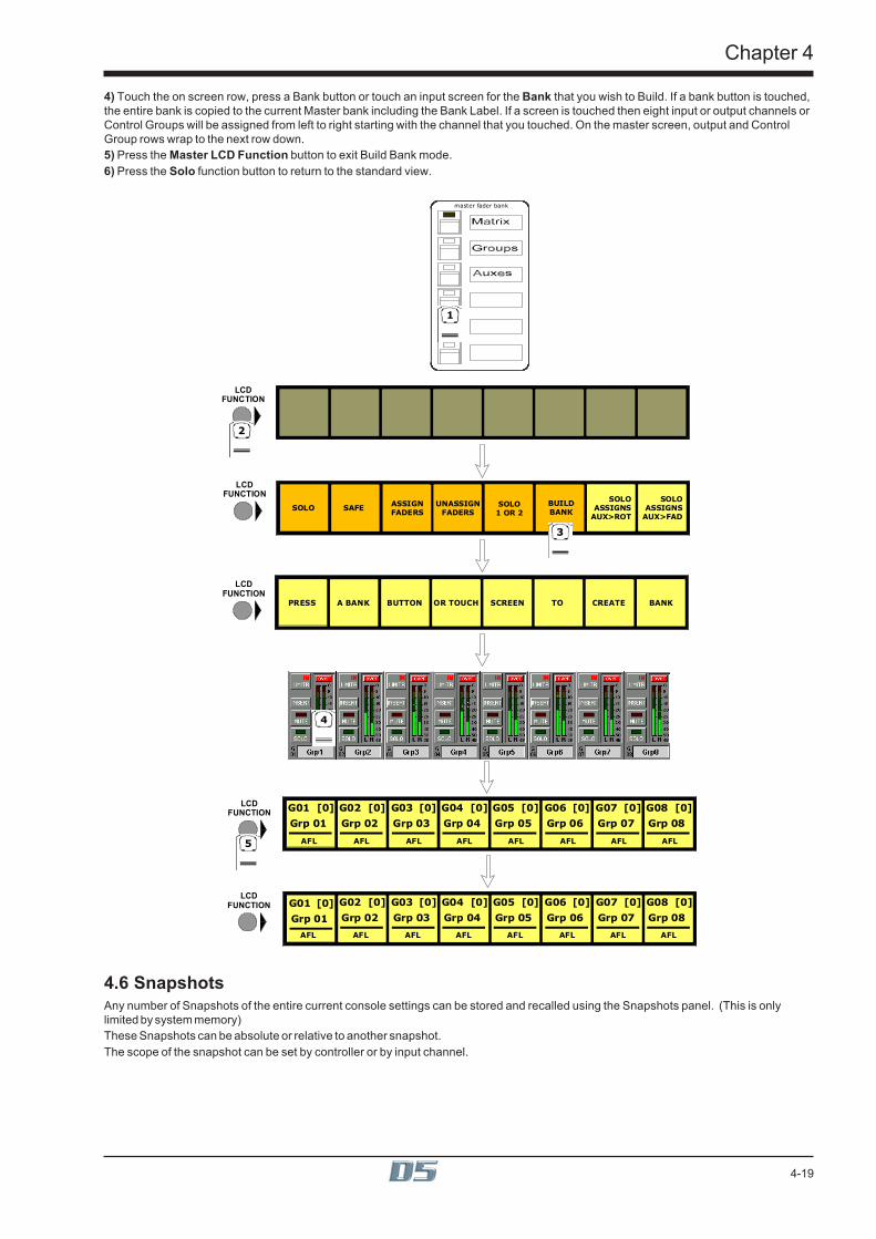
4-19
Chapter 4
4) Touch the on screen row, press a Bank button or touch an input screen for the Bank that you wish to Build. If a bank button is touched,the entire bank is copied to the current Master bank including the Bank Label. If a screen is touched then eight input or output channels orControl Groups will be assigned from left to right starting with the channel that you touched. On the master screen, output and ControlGroup rows wrap to the next row down.5) Press the Master LCD Function button to exit Build Bank mode.6) Press the Solo function button to return to the standard view.
SOLO
Grp 01
G01 [0]LCD
FUNCTION
SOLO SAFE
SOLO
Grp 02
G02 [0]
SOLO
Grp 03
G03 [0]
SOLO
Grp 04
G04 [0]
SOLO
Grp 05
G05 [0]
SOLO
Grp 06
G06 [0]
SOLO
Grp 07
G07 [0]
SOLO
Grp 08
G08 [0]
LCDFUNCTION
2
3
ASSIGN ASSIGN
LCDFUNCTION
Grp 01
G01 [0]LCD
FUNCTIONGrp 02
G02 [0]
Grp 03
G03 [0]
Grp 04
G04 [0]
Grp 05
G05 [0]
Grp 06
G06 [0]
Grp 07
G07 [0]
Grp 08
G08 [0]
PRESS A BANK BUTTON OR TOUCH SCREEN TO CREATE BANK
LCDFUNCTION
ASSIGN ASSIGN
Grp 02
G02 [0]
Grp 03
G03 [0]
Grp 04
G04 [0]
Grp 05
G05 [0]
Grp 06
G06 [0]
Grp 07
G07 [0]
Grp 08
G08 [0]
Grp 01
G01 [0]
5
4
master fader bank
1
AFL AFL AFL AFL AFL AFL AFL AFL
SOLOASSIGNSAUX>FAD
BUILDBANK
ASSIGNFADERS
UNASSIGNFADERS
SOLO1 OR 2
SOLOASSIGNSAUX>ROT
AFL AFL AFL AFL AFL AFL AFL AFL
4.6 SnapshotsAny number of Snapshots of the entire current console settings can be stored and recalled using the Snapshots panel. (This is onlylimited by system memory)These Snapshots can be absolute or relative to another snapshot.The scope of the snapshot can be set by controller or by input channel.
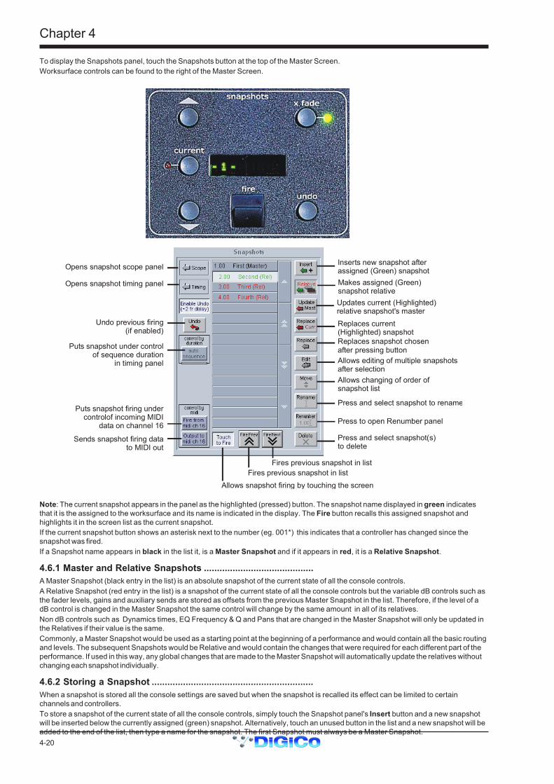
Chapter 4
4-20
To display the Snapshots panel, touch the Snapshots button at the top of the Master Screen.Worksurface controls can be found to the right of the Master Screen.
Makes assigned (Green) snapshot relativeUpdates current (Highlighted)relative snapshot's masterReplaces current (Highlighted) snapshotReplaces snapshot chosen after pressing button
Inserts new snapshot after assigned (Green) snapshot
Allows editing of multiple snapshotsafter selectionAllows changing of order ofsnapshot list
Press and select snapshot to rename
Press to open Renumber panel
Press and select snapshot(s)to delete
Opens snapshot scope panel
Opens snapshot timing panel
Undo previous firing (if enabled)
Puts snapshot under controlof sequence duration
in timing panel
Fires previous snapshot in listFires previous snapshot in list
Allows snapshot firing by touching the screen
Puts snapshot firing under controlof incoming MIDI
data on channel 16
Sends snapshot firing data to MIDI out
Note: The current snapshot appears in the panel as the highlighted (pressed) button. The snapshot name displayed in green indicatesthat it is the assigned to the worksurface and its name is indicated in the display. The Fire button recalls this assigned snapshot andhighlights it in the screen list as the current snapshot.If the current snapshot button shows an asterisk next to the number (eg. 001*) this indicates that a controller has changed since thesnapshot was fired.If a Snapshot name appears in black in the list it, is a Master Snapshot and if it appears in red, it is a Relative Snapshot.
4.6.1 Master and Relative Snapshots ..........................................A Master Snapshot (black entry in the list) is an absolute snapshot of the current state of all the console controls.A Relative Snapshot (red entry in the list) is a snapshot of the current state of all the console controls but the variable dB controls such asthe fader levels, gains and auxiliary sends are stored as offsets from the previous Master Snapshot in the list. Therefore, if the level of adB control is changed in the Master Snapshot the same control will change by the same amount in all of its relatives.Non dB controls such as Dynamics times, EQ Frequency & Q and Pans that are changed in the Master Snapshot will only be updated inthe Relatives if their value is the same.Commonly, a Master Snapshot would be used as a starting point at the beginning of a performance and would contain all the basic routingand levels. The subsequent Snapshots would be Relative and would contain the changes that were required for each different part of theperformance. If used in this way, any global changes that are made to the Master Snapshot will automatically update the relatives withoutchanging each snapshot individually.
4.6.2 Storing a Snapshot ..............................................................When a snapshot is stored all the console settings are saved but when the snapshot is recalled its effect can be limited to certainchannels and controllers.To store a snapshot of the current state of all the console controls, simply touch the Snapshot panel's Insert button and a new snapshotwill be inserted below the currently assigned (green) snapshot. Alternatively, touch an unused button in the list and a new snapshot will beadded to the end of the list, then type a name for the snapshot. The first Snapshot must always be a Master Snapshot.
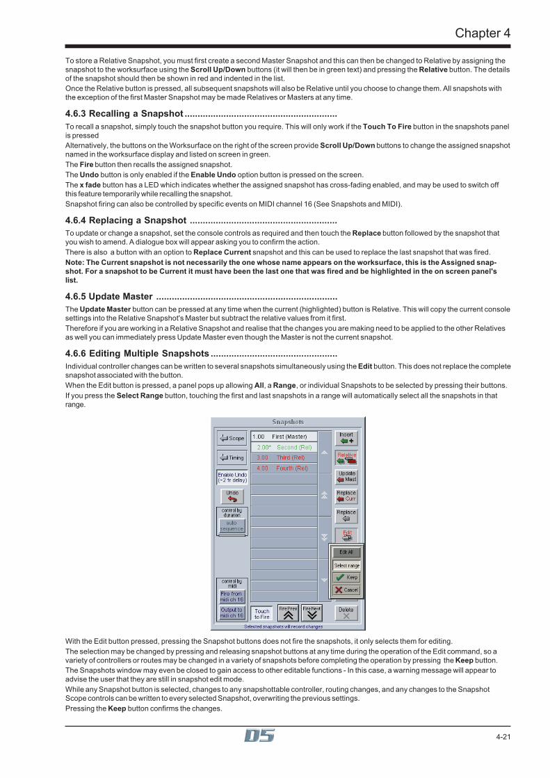
4-21
Chapter 4
To store a Relative Snapshot, you must first create a second Master Snapshot and this can then be changed to Relative by assigning thesnapshot to the worksurface using the Scroll Up/Down buttons (it will then be in green text) and pressing the Relative button. The detailsof the snapshot should then be shown in red and indented in the list.Once the Relative button is pressed, all subsequent snapshots will also be Relative until you choose to change them. All snapshots withthe exception of the first Master Snapshot may be made Relatives or Masters at any time.
4.6.3 Recalling a Snapshot ...........................................................To recall a snapshot, simply touch the snapshot button you require. This will only work if the Touch To Fire button in the snapshots panelis pressedAlternatively, the buttons on the Worksurface on the right of the screen provide Scroll Up/Down buttons to change the assigned snapshotnamed in the worksurface display and listed on screen in green.The Fire button then recalls the assigned snapshot.The Undo button is only enabled if the Enable Undo option button is pressed on the screen.The x fade button has a LED which indicates whether the assigned snapshot has cross-fading enabled, and may be used to switch offthis feature temporarily while recalling the snapshot.Snapshot firing can also be controlled by specific events on MIDI channel 16 (See Snapshots and MIDI).
4.6.4 Replacing a Snapshot .........................................................To update or change a snapshot, set the console controls as required and then touch the Replace button followed by the snapshot thatyou wish to amend. A dialogue box will appear asking you to confirm the action.There is also a button with an option to Replace Current snapshot and this can be used to replace the last snapshot that was fired.Note: The Current snapshot is not necessarily the one whose name appears on the worksurface, this is the Assigned snap-shot. For a snapshot to be Current it must have been the last one that was fired and be highlighted in the on screen panel'slist.
4.6.5 Update Master ......................................................................The Update Master button can be pressed at any time when the current (highlighted) button is Relative. This will copy the current consolesettings into the Relative Snapshot's Master but subtract the relative values from it first.Therefore if you are working in a Relative Snapshot and realise that the changes you are making need to be applied to the other Relativesas well you can immediately press Update Master even though the Master is not the current snapshot.
4.6.6 Editing Multiple Snapshots .................................................Individual controller changes can be written to several snapshots simultaneously using the Edit button. This does not replace the completesnapshot associated with the button.When the Edit button is pressed, a panel pops up allowing All, a Range, or individual Snapshots to be selected by pressing their buttons.If you press the Select Range button, touching the first and last snapshots in a range will automatically select all the snapshots in thatrange.
With the Edit button pressed, pressing the Snapshot buttons does not fire the snapshots, it only selects them for editing.The selection may be changed by pressing and releasing snapshot buttons at any time during the operation of the Edit command, so avariety of controllers or routes may be changed in a variety of snapshots before completing the operation by pressing the Keep button.The Snapshots window may even be closed to gain access to other editable functions - In this case, a warning message will appear toadvise the user that they are still in snapshot edit mode.While any Snapshot button is selected, changes to any snapshottable controller, routing changes, and any changes to the SnapshotScope controls can be written to every selected Snapshot, overwriting the previous settings.Pressing the Keep button confirms the changes.

Chapter 4
4-22
For example, if Snapshots 1 and 2 are selected and the input gain for channel 1 is changed, subsequent recall of Snapshots 1 or 2 will setchannel 1’s input gain to the new value.Only channels which are altered while the Edit command is active will be affected and only in snapshots that are selected at the time.If Cancel is pressed instead of Keep, all snapshots changed since the Edit button was pressed are returned to their original states,irrespective of which are currently selected. This allows any accidental changes to be undone. If there is not enough memory to store acopy of every edited snapshot, a warning is displayed and the Cancel button is disabled.A change in any of the following settings can be copied to all selected snapshots in edit mode:Snapshottable controllersRoutingRelay outputsSelection of MIDI snapshotsCrossfade timesControl Group membersGang membersAll Channels and Exclude buttons in Channel ScopeNOTE: Banks (Layout) settings are excluded from the Edit operation, since it is likely that scrolling, etc. may be needed to accesschannels which need to be changed without wanting to change the stored layout.Changing Snapshot Banks can only be done with the Replace command on one snapshot at a time. If you recall the Snapshot beforechanging the layout, all other settings stored in the Snapshot will remain unchanged.Touching faders to add or remove channels to or from the scope is also copied to all snapshots selected for Editing, but note that thechoice between add or remove depends on the currently displayed list.IMPORTANT NOTE:When editing the channel scope by touching faders, the Snapshot with the light horizontal line next to it whose Scope is currently beingdisplayed will be updated whether it is selected for editing or not.During the Edit command, all other scope controls do not affect the snapshot whose scope is being displayed, only those snapshotsselected for editing.
4.6.7 Moving a Snapshot ..............................................................If you wish the Snapshot list to appear in a specific order, you may change the order of the list by moving the entries. Touch the Movebutton and then touch the Snapshot that you wish to move. You then touch the point in the list where the snapshot should be moved to.Note: If a Relative Snapshot is moved above its own Master Snapshot in the list it will become Relative to the previous MasterSnapshot, but only when it is fired. Therefore the list can be rearranged in any way without changing the data in the snap-shots.
4.6.8 Renaming a Snapshot .........................................................To rename a snapshot, touch the Rename button, then the name that you wish to change and enter a new name using the keyboard.
4.6.9 Renumbering Snapshots ..............................................................As snaposhots can be inserted at any point in the list you may find that you wish to renumber part or all of the list.Press the Renumber button at the bottom of the snapshots panel and a new panel will open. Enter the range that you wish torenumber using the up/down arrows or by touching the entry and typing and then enter the steps to renumber to (1.00 is the default value).Then press the Renumber button and the list will be adjusted accordingly.
4.6.10 Deleting a Snapshot ..........................................................To delete a snapshot, touch the Delete button and then the Snapshot that you wish to delete. You will then be required to confirm thedeletion.Note: You cannot delete the first Master Snapshot in the list if it has Relative Snapshots below it.
4.6.11 Snapshot Undo ..................................................................If the button labelled Enable Undo is pressed, an undo button will appear and the worksurface undo button will be enabled.When a snapshot is fired, a separate hidden snapshot of the complete console is stored before the fired snapshot has its effect.If the Undo button is pressed, the hidden snapshot is fired using the same scope as the previously fired snapshot to undo its effect.This sampling before firing can take up to two frames to store depending on console configuration and should therefore be switched off insituations where timing is important (eg when synchronising snapshots to MIDI)Note: The Undo remains possible throughout any subsequent operation - changes to controllers will be undone along with the last firedsnapshot if the Undo button is pressed, unless it is switched off or the console structure changes.

4-23
Chapter 4
4.6.12 The Snapshot Scope Editor .............................................
When a snapshot is stored all the console settings are saved but when the snapshot is recalled its effect can be limited to certainchannels and controllers.Pressing the Scope button expands the panel to display and edit the scope for one snapshot, indicated by a light band linking thesnapshot list to the scope. The scroll buttons in the centre of the panel move the scope editing up and down the snapshot list.If the Preview button is pressed the scope for the next snapshot in the list is displayed.
4.6.13 Channel Scope ...................................................................The input channels which are included in each snapshot can be set by pressing the Touch Faders To Select button and touching therequired faders which will be added to the list (touching a fader again will remove it from the list).Press the All Channels button if the snapshot is to be global.If the Exclude button at the bottom left of the panel is pressed then the snapshot will apply to all the channels which are not on the list.Note: If both All Channels and Exclude are highlighted, the snapshot will have no effect on any input channels.Channel scope is not applied when recalling Banks (layouts).
4.6.14 Controller Scope ................................................................Each snapshot can have its own individual controller recall scope. Pressing the scope buttons includes the item in the scope.
ControllersThe first eight Controller scope buttons relate to input channels only.Input - digital trim, delay, label, input balance, MS decode, left right swap. EXCLUDES Stereo switch.EQ - all controllers.Dynamics - all controllers except stereo link.Aux Sends - aux send level, on/off, pan, pre/post.Panning - panner, divergence, sub level.Mute - channel mute switch.Fader - channel fader.Bussing - buss routing buttons.Effects - all FX controllers. EXCLUDES FX configuration (Presets).Processors - IPC controllers.Matrix - Matrix Groups - all controllers including EQ, Dynamics and label.Auxes - Aux buss outputs - all controllers and label.Groups - Group buss outputs - all controllers and label.Main - Master buss outputs - all controllers and label.
RoutingInput - Channel and Matrix input routing, label, analogue gain and 48v switch.Inserts - Input channel send and return routes, send gain, -10dB, pre/post switch and insert in/out.If Buss Controllers are included in the scope this also includes buss inserts.Directs - Input channel send route, send gain, -10dB and pre/post switch.Matrix I/O - Matrix Groups output and direct routing and -10dB switch.Processors I/O - IPC output and direct routing and -10dB switch.Out - If Buss Controllers are included in the scope this includes the relevant buss output routing and -10dB switch.
MiscCG Members - Control Group label and a complete list of each group’s members.CG Faders - Control Group faders only.

Chapter 4
4-24
Gangs - Input channel gang members.Banks - Each cue stores the current assignment for all controllers on the worksurface:Fader banks currently assigned to input surfaces but not the names of these banks.Which channel on each surface is assigned to EQ/Dynamics/Joystick controls.Which rows of pans or auxes are assigned to rotaries.The Master Fader Banks assignment.Note: Banks are not intended to reproduce the exact screen states. Channel views and other panels’ visibilities are not storedor recalled.MIDI - Fires the MIDI Patch associated with the cue.Relays - The sixteen red indicators below the Relay scope button represent the state of the relays which will be output when the cue isfired (not the current state). It is stored at the time the cue is recorded and can be edited by clicking on individual indicators with thetrackball.
RestrictionsImportant Note: The following features are not included in snapshots:The input channel stereo switch.Dynamics stereo link.Talkback.Channel Bank names.Choice of Solo 1 or Solo 2.Effects Preset selection
4.6.15 Snapshot Timing ................................................................To automatically sequence the firing of snapshots:1) Select the snapshots using the up/down arrows in the centre of the panel.2) Press the Fire Next After button on the left hand side and enter a time in the boxes next to this button.3) Activate the function by firing the snapshot or pressing the Auto Sequence button.When this snapshot is fired, the next snapshot in the list will automatically be fired after the set time has elapsed and a red progress barwill show the time remaining until the snapshot is fired. Pressing the Auto Sequence button while the progress bar is moving will halt theprocess.
Each snapshot may also trigger Play From, Play To and Locate To timecode commands.Select the required snapshot and enter a timecode value in the relevant box. Then activate the function by pressing the required button(s).Play From does a Locate then presses Transport Play if not already playing.Play To presses Transport Play if not already playing, and sets up an automatic Transport Stop when the Play To time is reached.If Play To and Locate To are specified together in one cue, when the PlayTo time is reached, a Locate will be generated after theTransport Stop.If Locate To is specified on its own, it simply does the Locate.Any manual transport control cancels any pending Stops or Locates.
CrossfadesA crossfade time which is measured in frames can be applied to a Snapshot by adjusting the Crossfade Time in the Timing panel. Eitheruse the Up/Down arrows or type a value into the box. The x fade light on the worksurface will be illuminated when the currently assignedSnapshot has crossfading enabled. The button next to it may be pressed to temporarily disable crossfading while recalling this snapshotbut it does not change the crossfade time itself.The Crossfade time is applied to faders, matrix sends and pans only (including sub level and LR/LCR blend). A value of zero switches itoff.

4-25
Chapter 4
4.6.16 Snapshots and MIDI ...........................................................There are two separate areas of MIDI control.1) A snapshot can have a MIDI Patch attached to it, and will output that MIDI when fired. The MIDI Patch must be created separately inthe Setup Menu / MIDI Patches panel. Switching the MIDI scope on pops up a panel prompting for a MIDI Patch button to be pressed,which will then be linked to the snapshot whose scope is currently displayed.2) The firing of snapshots can be controlled by incoming MIDI messages on channel 16, and can cause these same messages to beoutput in addition to any MIDI snapshots included in (1) above.The MIDI Input Control button allows the Snapshot system to respond to the following incoming MIDI messages:-General Purpose Controller A (Controller 16); Values 0 to 127 will fire snapshots 1 to 128General Purpose Controller B (Controller 17); Values 0 to 127 will fire snapshots 129 to 256General Purpose Controller C (Controller 18); Values 0 to 127 will fire snapshots 257 to 384.General Purpose Controller D (Controller 19); Values 0 to 125 will fire snapshots 385 to 510.General Purpose Controller D (Controller 19); Value 126 will fire the previous snapshot in list.General Purpose Controller D (Controller 19); Value 127 will fire the next snapshot in list.MIDI Output causes the above messages 1 to 510 to be sent whenever a snapshot button is pressed. Previous and Next buttons do notoutput MIDI messages of their own.
4.6.17 MIDI Patches .......................................................................The console's main MIDI port is known as MIDI port T. If your D5 is fitted with the combination MIDI/GPI/GPO card it can also have 2more MIDI ports A & B (Each card provides 16 extra MIDI channels - A1 to A16 on the first card and B1 to B16 on the second card.)The port letter may be prefixed on any line of the MIDI Patches Editor before the MIDI channel number (separated by spaces). If the portletter is omitted, Port T is assumed. Touching the MIDI Patch button in the Setup menu opens the MIDI Patches panel which allows anyMIDI program change, controller change, note on or off message to be recorded and played back manually or against timecode.
This panel is implemented just like existing (“controller”) snapshots.MIDI is received and transmitted via the timecode card. An indicator on the MIDI panel shows when any MIDI data is being received.When the Capture button is pressed a text panel is displayed and any incoming MIDI controller or program change information isrecorded. There is also a list of required syntax for entering the text manually.The captured text may be edited or new text entered into an existing patch by touching the Edit button and typing. This text is thencompiled into the required stream of MIDI data when OK is pressed. Errors are reported at this stage.The correct format for the messages is as follows:Note OnThe MIDI Port Number (Port T is assumed if there is no entry here)A 2 digit MIDI Channel number between 01 and 16N+ to indicate Note OnA note number between 0 and 127A velocity value between 0 and 127eg. A 01 N+ 60 127Note OffThe MIDI Port Number (Port T is assumed if there is no entry here)A 2 digit MIDI Channel number between 01 and 16N- to indicate Note OffA note number between 0 and 127A velocity off value between 0 and 127eg. A 01 N- 60 127

Chapter 4
4-26
Program ChangeThe MIDI Port Number (Port T is assumed if there is no entry here)A 2 digit MIDI Channel number between 01 and 16P to indicate Program ChangeA program number between 0 and 127eg. A 01 P 127Control ChangeThe MIDI Port Number (Port T is assumed if there is no entry here)A 2 digit MIDI Channel number between 01 and 16C to indicate Control ChangeA controller number between 0 and 127An equals sign (Optional)A controller value between 0 and 127eg. A 01 C 11 = 64The words Program and Controller may be used or just their initial letters (case-insensitive). The equals sign is optional.Comments are not stored although anything on a line after a semicolon is ignored. The first message in the editor is used as the patchname on the button label but this may be edited.When not capturing, editing, renaming or deleting, the patch buttons will output the stored MIDI data when pressed.
MIDI Sequence FilesMIDI sequence files can be played out of ports A and B. They must be .MID files in format 0 (one track only) and are quoted in the MIDIPatches Editor as:
<port> file <filename> eg. A file test.mid
A path can precede the filename, otherwise the current session folder is assumed. Only short filenames with a maximum of 8 charactersand no punctuation are accepted.This file is then downloaded to the card and starts playing when the MIDI Patch is fired. The Sequence File Start and Play buttons on theMIDI Patch panel then become effective. Press Stop to pause, then Play to restart from the same place or re-fire the MIDI Patch to playagain from the beginning of the file. This remains possible until the file is played to the end or another Patch is fired with another se-quence file for the same port. Other MIDI messages may be sent to the same port without affecting the sequence playbackMIDI Patches are stored in session files. The New Session panel has a Clear option for MIDI which deletes all MIDI Patches leaving anempty list.

4-27
Chapter 4
4.7 Transport / Timecode ConfigurationWhen the D5 is used in typical live sound applications there will be no time related control systems (timecode) or motioncontrol (tape transport) connected. Synchronisation and machine control does not need to be considered.This panel can be accessed by touching the Setup button on the Master screen and then touching the Transport & Timecode button.
Frame RateThis must be set up for the frame rate used by your other equipment. You can select from four different basic frame rates, with a drop-frame option available for 29.97 and 30 fps.
Timecode SourceYou can choose the Console option to make the console generate the master timecode for the setup, or you can choose to make theconsole "chase" timecode which arrives at one of the external sockets - SMPTE (LTC), MIDI (MTC), or 9-pin. These external sockets arelocated on the console rear panel.The 9-pin Eavesdrop option requires a special 9-pin cable (See technical manual for details). The option is provided for installationswhere the 9-pin connection runs between two other pieces of equipment (for example, a video machine and DAW), but the console isrequired to chase this timecode. 9-pin does not normally allow more than a single direct connection between two machines, but using theEavesdrop cable, you can make the console "listen" to the timecode passing between two other machines, and to sync to and display thistimecode on the worksurface.Note that if you are using 9-pin Eavesdrop mode, you cannot use any of the options for direct 9-pin connection.Timecode Output EnableWhether the console is operating as timecode master or deriving its timecode from another device, you can choose to route a timecodesignal out from the MIDI (MTC) and/or SMPTE (LTC) sockets. If timecode is being received from another device it is regenerated beforebeing routed to the output.
Machine Control EnableThe console can only send Control signals if you have enabled a Machine Control output. This can be MIDI Machine Control (MMC) and/or 9-pin Disk or Tape. Note that you cannot output 9-pin control if you are using the Eavesdrop option to read timecode.MIDI Machine Control has limited transport features, supporting only the Play, Record, FF, Rewind, Stop and Locate functions. 9-pincontrol supports Shuttle and Jog functions.
Off-line ButtonsThe configuration panel allows you to temporarily disable all timecode and transport control to any combination of outputs. The ALL buttondisables all timecode and machine control output - this is especially useful to prevent external machines trying to chase the consoletimecode.
Video Sync Lock IndicatorBy connecting a video or black/burst signal to the video frame sync input on the worksurface rear panel, you can provide an external framesync for the timecode. If the console is acting as timecode master or regenerating timecode, the frame boundaries in the timecode arethen locked to those on the incoming video signal. If the lock is operating, the green indicator on the panel lights up to indicate this.

Chapter 4
4-28
4.8 Audio SynchronisationNOTE: Versions of D5 software previous to V3 could not be synced to an external source when the system was connected withOptocore. This was only possible with MADI connections.In V3 and above, external sync can be used with either type of connection.The recommended method for implementing external sync is to use a Word Clock source connected to the DiGirack's Sync In socket.This will be automatically sensed and used as the Master Sync Source. If connected with Opt ocore, the other devices in the system canbe set to Optocore sync in the standard way.If the system is to be synced to a different type of source then this should be connected to the relevant console Sync In (eg AES or Video)socket and the console's Audio Sync panel should be set to reflect this. In this case the external sync source should be seperatelydistributed to all the other components of the system.The console will operate in a self contained manner, operated as master sync source, usually at 48KHz, see below for setting this. Thiswill be the case even if some of the external equipment is in fact digital eg. digital delays, as long as their connections are analogue. Froma system point of view this is the simplest mode of operation.However as the D5 offers digital audio interfacing and therefore synchronisation must be considered, if this is to be used.To ensure glitch-free audio, digital signals must be correctly synchronised using a "Word Clock" or "Digital Sync". The D5 console can actas Master, generating the word clock for other digital units in the system, or it can slave to an external digital sync input. External synccan be derived either from a dedicated sync unit, or from an incoming digital audio signal connected via an AES/EBU or MADI signalinput.The digital sync source will usually be set up when the console is installed, but it can be altered using the Audio Sync button in the SetupMenu. Pressing this button displays the Audio Sample Clock Sync control panel:
4.8.1 Internal Sync - Console As Master .....................................If you choose to use the console as the master sync source, you can select a standard sample rate with the 44.1KHz or 48KHz buttonsand the adjust it if necessary in steps of +/- 0.1% or +/- 100Hz and 1Hz.
4.8.2 External Sync .......................................................................WARNING! Operators should be aware that it is normal for a misclocked or unclocked digital audio system to produce loud, randomnoises. This can be damaging to external systems, especially large PA systems. Take care to disable such systems until the digital synchas been properly established and proved to be stable.When you choose to sync to an external source, the control panel will immediately try to find the sync source you specify, and display awarning if no sync can be found, as shown in the illustration below.The presence of a valid sync source is indicated by the green OK lights, not by the button. If the selected sync source should disappear,this panel will automatically be displayed with the warning message.

4-29
Chapter 4
4.8.3 External Sync Sources ........................................................Word Clock and AES/EBUThe worksurface rear panel has connectors for Word Clock and AES/EBU inputs, either of which can be used as the master sync sourceby pressing the appropriate on-screen button - note that the AES/EBU worksurface input is for sync only, and cannot be used for audio.
Video SyncAlso located on the worksurface rear panel is the Video Sync input. Although this carries only a frame boundary signal, the console cangenerate a full digital word-clock from it. This means that when you choose to sync to the video signal, you have to choose the samplerate you want to generate between frame boundaries, in just the same way as when the console is providing the master sync.
Sync to Audio SignalAny of the console's digital audio inputs can be selected as sync source. If you choose the Audio Signal option in the Sync control panel,you can then choose any input signal group and number, in just the same way as the audio component of the signal is selected as thesource for a console input channel. When you have selected a signal group, the panel displays a green "OK " light to indicate when asignal in that group carries a valid sync source.Please note the Digico's experience shows by far the most trouble free master sync source will be an AES/EBU signal (from the AES syncinput or audio input). Word clock is second best and video is the more difficult source to implement.
4.8.4 Sample Rate and Conversion .............................................The default sample rate for the console is set up at installation, and it is this sample rate which will be used when the console is operatingas the master digital sync source. If the console is synchronised with an external digital audio unit, the sample rate used by the externalunit becomes the master sample rate for the system.
Sample Rate ConvertorsThe AES/EBU Rack Modules are equipped with input Sample Rate Convertors (SRC). By default these are switched on at all times.These allow the console to synchronise incoming digital signals of differing sample-rates, to avoid the glitching which occurs when signalswith different sample-rates are mixed.SRC also allows the same sample rate but different clock phase to be connected without problems (such as systems locked to externalvideo sources).
SRC is also provided on the AES/EBU outputs. By default the outputs are locked to the console rate, however other rates can be preset tospecific outputs, for example to allow a 44.1KHz output to a CDR from a console running 48KHz.
Switching of both the input and output SRC is not adjustable from the console screens but is configured in the socket setup file of thecontrol computer, as this requires careful consideration of clocking issues within the system as a whole. For most users the default setupwill work for the majority of applications.

5-1
Chapter 5
Chapter 5Effects and
Insertable Processing Channels

5-2
Chapter 5

5-3
Chapter 5
5.1 Configure EffectsIf The Effects and/or Processing Channel modules are not active, touch Setup / Service / Configure Hardware button to open theDiGiConfig program, select the console that you want to configure by pressing the relevant This button, then tick the relevant boxes at thetop of the panel and press OK.The optional effects section provides up to 6 different effects modules - each FX module can be made Safe from Snapshots by pressingthe on screen Safe button in the relevant FX parameters panel.FX1 is always a stereo reverb unit and is the only one that can use the top line of reverb presets.FX2, 3 and 4 can be configured as reverbs or any of a selection of other effects.FX5 and 6 can function as effects modules but can also provide Output Processing on stereo, LCRS or 5.1 output busses or Graphic EQ.Note: Only one Delay preset can be used between the 6 FX slots. For example, if a delay effect is selected for FX2 then all delaypresets will become unavailable for the other FX slots.
5.1.1 Selecting Effects ..................................................................Touching the Configure Effects button in the Setup menu on the Master Screen opens the following panel:
Touch one of the buttons on the left to select an effects module and assign an effect to it by selecting from the grid of buttons labelled withthe effect names.Reverb (FX1)Selection of an effect for the first module labelled Reverb can only be made from the first page of 30 reverb effects.Other Effects (FX2, FX3 and FX4)Selection for modules 2, 3 and 4 can be made from a similar list of reverb effects but by selecting the tab labelled Other Effects there arefurther choices including delay, chorus flange and pitch shifters.
Output Processing and Graphic EQ (FX5 and FX6)Selection for modules 5 or 6 can be from the Reverb or Other Effect lists but the Output Processing tab also becomes available and youmay choose the type of signal that you wish to process or apply mono or stereo Graphic EQ.The processing options are Stereo, LCRS, 5.1 or 7.1 or up to 12 mono Graphic EQs.
Output Processing consists of input and output gain, 3 band compression and limiting and 4 band EQ for each channel.Graphic EQ consists of 12 independent 28 band EQ's.
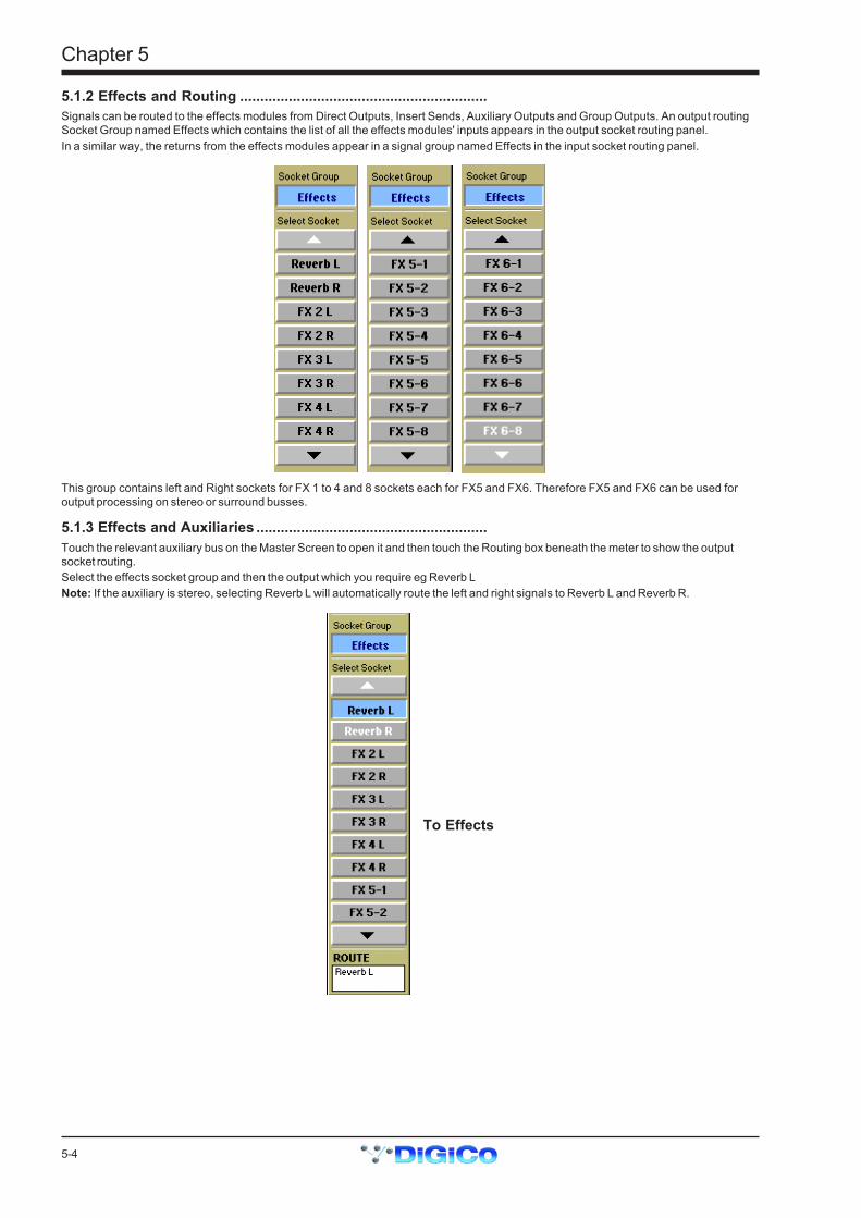
5-4
Chapter 5
5.1.2 Effects and Routing .............................................................Signals can be routed to the effects modules from Direct Outputs, Insert Sends, Auxiliary Outputs and Group Outputs. An output routingSocket Group named Effects which contains the list of all the effects modules' inputs appears in the output socket routing panel.In a similar way, the returns from the effects modules appear in a signal group named Effects in the input socket routing panel.
This group contains left and Right sockets for FX 1 to 4 and 8 sockets each for FX5 and FX6. Therefore FX5 and FX6 can be used foroutput processing on stereo or surround busses.
5.1.3 Effects and Auxiliaries .........................................................Touch the relevant auxiliary bus on the Master Screen to open it and then touch the Routing box beneath the meter to show the outputsocket routing.Select the effects socket group and then the output which you require eg Reverb LNote: If the auxiliary is stereo, selecting Reverb L will automatically route the left and right signals to Reverb L and Reverb R.
To Effects
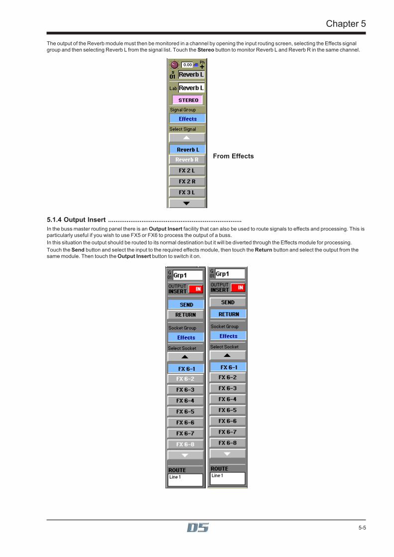
5-5
Chapter 5
The output of the Reverb module must then be monitored in a channel by opening the input routing screen, selecting the Effects signalgroup and then selecting Reverb L from the signal list. Touch the Stereo button to monitor Reverb L and Reverb R in the same channel.
From Effects
5.1.4 Output Insert ........................................................................In the buss master routing panel there is an Output Insert facility that can also be used to route signals to effects and processing. This isparticularly useful if you wish to use FX5 or FX6 to process the output of a buss.In this situation the output should be routed to its normal destination but it will be diverted through the Effects module for processing.Touch the Send button and select the input to the required effects module, then touch the Return button and select the output from thesame module. Then touch the Output Insert button to switch it on.
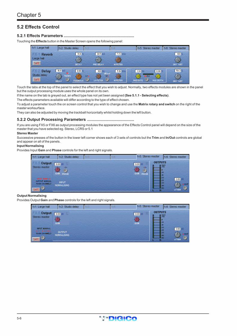
5-6
Chapter 5
5.2 Effects Control
5.2.1 Effects Parameters ...............................................................Touching the Effects button in the Master Screen opens the following panel:
Touch the tabs at the top of the panel to select the effect that you wish to adjust. Normally, two effects modules are shown in the panelbut the output processing module uses the whole panel on its own.If the name on the tab is greyed out, an effect type has not yet been assigned (See 5.1.1 - Selecting effects).The effects parameters available will differ according to the type of effect chosen.To adjust a parameter touch the on screen control that you wish to change and use the Matrix rotary and switch on the right of themaster worksurface.They can also be adjusted by moving the trackball horizontally whilst holding down the left button.
5.2.2 Output Processing Parameters ..........................................If you are using FX5 or FX6 as output processing modules the appearance of the Effects Control panel will depend on the size of themaster that you have selected eg. Stereo, LCRS or 5.1Stereo MasterSuccessive presses of the button in the lower left corner shows each of 3 sets of controls but the Trim and In/Out controls are globaland appear on all of the panels.Input NormalisingProvides Input Gain and Phase controls for the left and right signals.
Output NormalisingProvides Output Gain and Phase controls for the left and right signals.

5-7
Chapter 5
Main Channels DynamicsProvides Crossover adjustment, 3 band compression and Limiting.
Click here to changeparameter view
Click here to viewThreshold
AttackRelease
Ratio
Click here to view Limiter
Threshold or Release
Processing In/Out
Main EQProvides 4 Band EQ with adjustable Filter Types on Bands 1 and 4.
Click here to changeBand 1 Filter Type
Click here to changeBand 4 Filter Type
Set EQ Flat
LCRS MasterThe controls for an LCRS Master are the same as stereo (See previous section) but the Input and Output Normalising panels allowseparate Gain and Phase control for each of the four signals.
5.1 MasterA 5.1 Master provides separate Input and Output Normalising for each of the six signals and in addition the Sub Channel has its ownCompressor, Limiter and 4 Band EQ.
Sub Channel Dynamics
Sub Channel EQ

5-8
Chapter 5
Graphic EQThe controls for the 12 Graphic EQs are as follows:
Click here to selectwhich Graphic EQto adjust (1 of 6)
Touch faders on screento assign control toworksurface master
faders
Processing In/OutTrim Control
Reset Flat
Click here to link EQs in stereo pairs
If a stereo source is being processed the EQs can be linked in pairs - 1 and 2, 3 and 4, 5 and 6.When connecting channels or busses to the Graphic EQs each unit will appear in the Effects socket group as a different number.If FX 5 is configured as a Graphic EQ the six units are FX 5-1, FX 5-2, FX 5-3, FX 5-4, FX 5-5 and FX 5-6.If FX 6 is configured as a Graphic EQ the six units are FX 6-1, FX 6-2, FX 6-3, FX 6-4, FX 6-5 and FX 6-6.
5.3 Processing ChannelsIf you have activated the 32 Processing Channels in the DiGiConfig program (Setup Menu / Service / Configure Hardware), four of theconsole's Channel Fader Banks will contain panels like the one pictured below. They will initially be labelled Pr 1-32 in blocks of eight.
Delay Time
Delay In/Out
CompressorThresholdCompressorIn/Out
Output RoutingLabel
Trim
SoloMute
These channels provide Trim, Delay up to 510ms (with fine adjustment to sample level), Compression and 6 Band Parametric EQ andmay be inserted into the signal path via Channel Direct Outs and Insert Points, Group, Auxiliary and Matrix Outputs or Insert PointsA Socket Group called Processors will be available in all of the routing panels which contains the inputs and outputs of these channels.
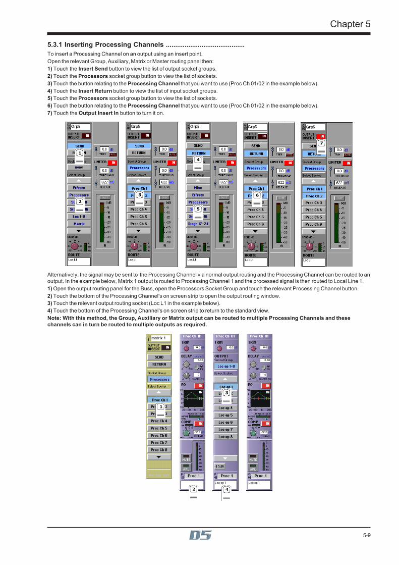
5-9
Chapter 5
5.3.1 Inserting Processing Channels ..........................................To insert a Processing Channel on an output using an insert point.Open the relevant Group, Auxiliary, Matrix or Master routing panel then:1) Touch the Insert Send button to view the list of output socket groups.2) Touch the Processors socket group button to view the list of sockets.3) Touch the button relating to the Processing Channel that you want to use (Proc Ch 01/02 in the example below).4) Touch the Insert Return button to view the list of input socket groups.5) Touch the Processors socket group button to view the list of sockets.6) Touch the button relating to the Processing Channel that you want to use (Proc Ch 01/02 in the example below).7) Touch the Output Insert In button to turn it on.
1
2
3
4
5
6
7
Alternatively, the signal may be sent to the Processing Channel via normal output routing and the Processing Channel can be routed to anoutput. In the example below, Matrix 1 output is routed to Processing Channel 1 and the processed signal is then routed to Local Line 1.1) Open the output routing panel for the Buss, open the Processors Socket Group and touch the relevant Processing Channel button.2) Touch the bottom of the Processing Channel's on screen strip to open the output routing window.3) Touch the relevant output routing socket (Loc L1 in the example below).4) Touch the bottom of the Processing Channel's on screen strip to return to the standard view.Note: With this method, the Group, Auxiliary or Matrix output can be routed to multiple Processing Channels and thesechannels can in turn be routed to multiple outputs as required.
1
2
3
4

5-10
Chapter 5
5.3.2 Processing Channel Controls .............................................Processing Channel controls can be accessed from the worksurface (See Diagram in Section 5.3) but by touching either the EQ graph orthe word "Comp" on the screen, further parameters become available.When the EQ panel is expanded, the 3 rows of rotaries and switches below the channel screen are assigned to the 3 rows of controls inthe EQ panel.When the compressor panel is expanded the first row of rotaries and switches below the channel screen is assigned to the row of controlsin the compressor panel.
Proc Channel EQ Presets
ResetFlat
In/Out Switches for eachof the six bands
Change filter type for band 1 Change filter type for band 6
Touching the EQ panel Presets button opens the Processing Channel EQ library and this functions in the same way as standardChannel, EQ and Dynamics Presets.

6-1
Chapter 6
Chapter 6Multiple Console Setups

6-2
Chapter 6
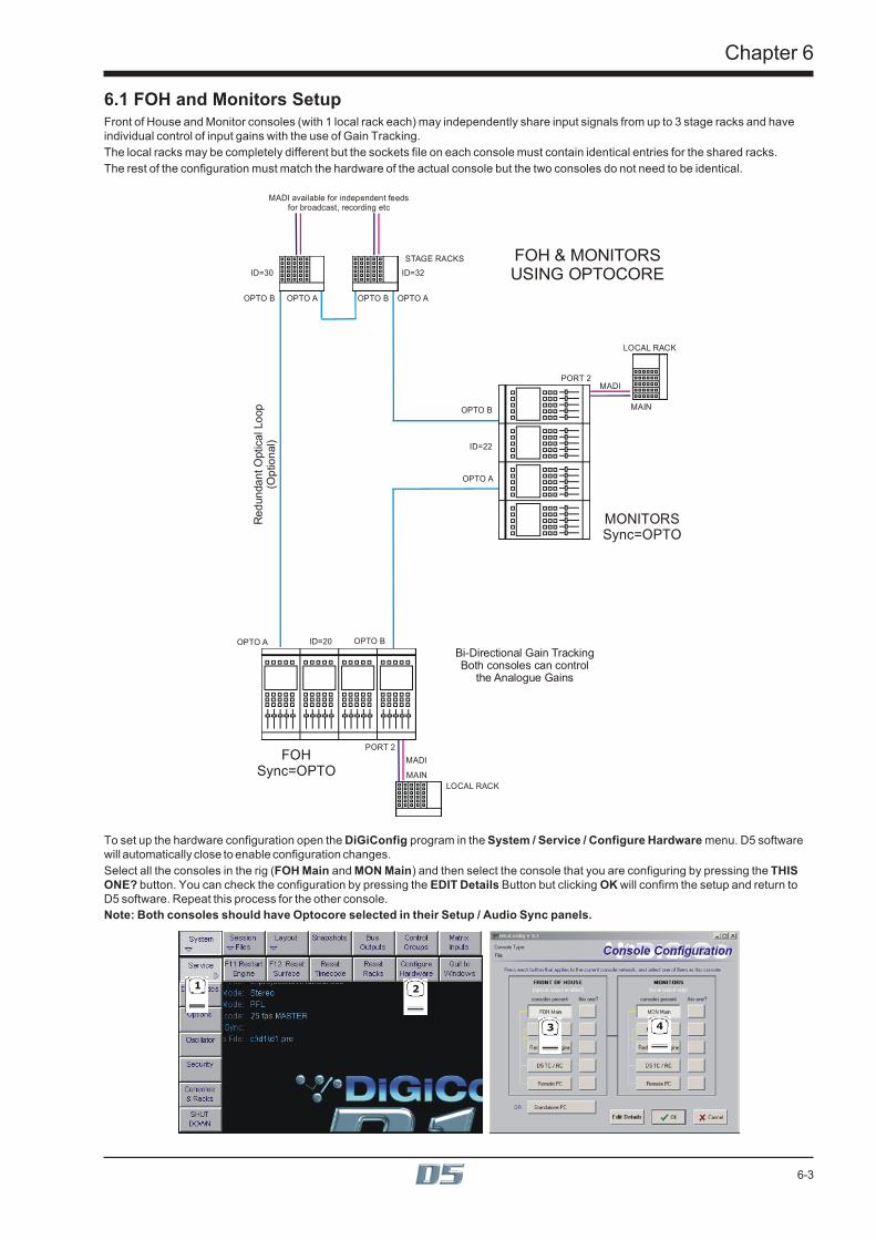
6-3
Chapter 6
6.1 FOH and Monitors SetupFront of House and Monitor consoles (with 1 local rack each) may independently share input signals from up to 3 stage racks and haveindividual control of input gains with the use of Gain Tracking.The local racks may be completely different but the sockets file on each console must contain identical entries for the shared racks.The rest of the configuration must match the hardware of the actual console but the two consoles do not need to be identical.
FOH & MONITORS USING OPTOCORE
MONITORSSync=OPTO
FOHSync=OPTO
STAGE RACKS
MADI available for independent feedsfor broadcast, recording etc
Bi-Directional Gain TrackingBoth consoles can control
the Analogue Gains
Red
unda
nt O
ptic
al L
oop
(Opt
iona
l)
LOCAL RACK
LOCAL RACK
OPTO A
OPTO B
OPTO B
OPTO A
OPTO A
PORT 2
PORT 2
OPTO B
ID=30 ID=32
ID=22
ID=20
OPTO BOPTO A
MAIN
MADI
MADI
MAIN
To set up the hardware configuration open the DiGiConfig program in the System / Service / Configure Hardware menu. D5 softwarewill automatically close to enable configuration changes.Select all the consoles in the rig (FOH Main and MON Main) and then select the console that you are configuring by pressing the THISONE? button. You can check the configuration by pressing the EDIT Details Button but clicking OK will confirm the setup and return toD5 software. Repeat this process for the other console.Note: Both consoles should have Optocore selected in their Setup / Audio Sync panels.
1 2
3 4
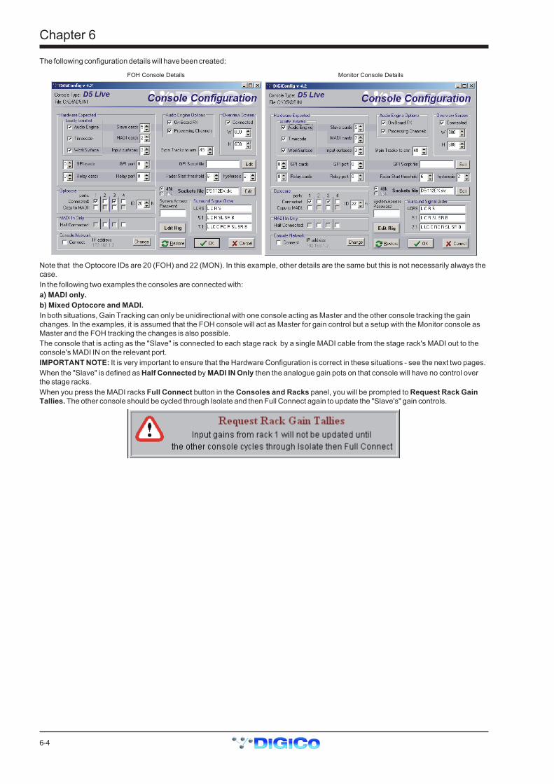
6-4
Chapter 6
The following configuration details will have been created:
FOH Console Details Monitor Console Details
Note that the Optocore IDs are 20 (FOH) and 22 (MON). In this example, other details are the same but this is not necessarily always thecase.In the following two examples the consoles are connected with:a) MADI only.b) Mixed Optocore and MADI.In both situations, Gain Tracking can only be unidirectional with one console acting as Master and the other console tracking the gainchanges. In the examples, it is assumed that the FOH console will act as Master for gain control but a setup with the Monitor console asMaster and the FOH tracking the changes is also possible.The console that is acting as the "Slave" is connected to each stage rack by a single MADI cable from the stage rack's MADI out to theconsole's MADI IN on the relevant port.IMPORTANT NOTE: It is very important to ensure that the Hardware Configuration is correct in these situations - see the next two pages.When the "Slave" is defined as Half Connected by MADI IN Only then the analogue gain pots on that console will have no control overthe stage racks.When you press the MADI racks Full Connect button in the Consoles and Racks panel, you will be prompted to Request Rack GainTallies. The other console should be cycled through Isolate and then Full Connect again to update the "Slave's" gain controls.

6-5
Chapter 6
MADI Connections OnlyThe recommended connection between the Monitor console and Stage Racks is a single MADI OUT from each Stage Rack's AUX MADIconnected to the console's MADI 1 IN for Stage Rack 1 and MADI 3 IN for Stage Rack 2.The FOH (Master console) is connected via MADI In and Out to both stage racks.Note: This configuration requires a Word Clock connection from the FOH to the Monitor console. The FOH console should be set toSetup / Audio Sync = Master and the Monitor console to Setup / Audio Sync = Word Clock.
FOH & MONITORS USING MADI ONLY
MONITORSSync = Word Clock
STAGE RACKS
Uni-Directional Gain TrackingFOH has control of the Analogue Gains
and Monitors can track this
LOCAL RACK
LOCAL RACK
AUXOUTONLY
AUXOUT
ONLY
PORT 3 IN
PORT 3
PORT 1 IN
WORD CLOCK
PORT 1
PORT 2
PORT 2
MAINMAIN
MAIN
MAIN
FOHSync = Master
For this setup the Hardware Configuration must be manually edited by pressing Edit Details.The FOH (Master) console should have no Optocore Connected boxes ticked and the Monitor console should be configured as beingMADI In Only for the relevant racks (in this case racks 1 and 3) by ticking the Half Connected boxes as below.
FOH Console fully connected with MADI (has gain control) Monitor Console with MADI IN only (can only track gain changes)
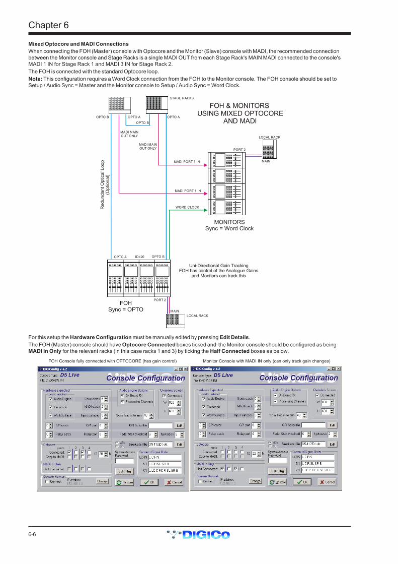
6-6
Chapter 6
Mixed Optocore and MADI ConnectionsWhen connecting the FOH (Master) console with Optocore and the Monitor (Slave) console with MADI, the recommended connectionbetween the Monitor console and Stage Racks is a single MADI OUT from each Stage Rack's MAIN MADI connected to the console'sMADI 1 IN for Stage Rack 1 and MADI 3 IN for Stage Rack 2.The FOH is connected with the standard Optocore loop.Note: This configuration requires a Word Clock connection from the FOH to the Monitor console. The FOH console should be set toSetup / Audio Sync = Master and the Monitor console to Setup / Audio Sync = Word Clock.
FOH & MONITORS USING MIXED OPTOCORE
AND MADI
MONITORSSync = Word Clock
STAGE RACKS
Uni-Directional Gain TrackingFOH has control of the Analogue Gains
and Monitors can track this
LOCAL RACK
LOCAL RACK
MADI MAINOUT ONLY
MADI MAINOUT ONLY
MADI PORT 3 IN
MADI PORT 1 IN
WORD CLOCK
PORT 2
PORT 2
MAIN
MAIN
FOHSync = OPTO
Red
unda
nt O
ptic
al L
oop
(Opt
iona
l)
OPTO BOPTO A
OPTO B
ID=20
OPTO A
OPTO B
OPTO A
For this setup the Hardware Configuration must be manually edited by pressing Edit Details.The FOH (Master) console should have Optocore Connected boxes ticked and the Monitor console should be configured as beingMADI In Only for the relevant racks (in this case racks 1 and 3) by ticking the Half Connected boxes as below.
FOH Console fully connected with OPTOCORE (has gain control) Monitor Console with MADI IN only (can only track gain changes)

6-7
Chapter 6
6.1.1 Gain Tracking Settings ........................................................With the Optocore connection, Gain Tracking can be bidirectional. If either console adjusts the analogue gain, the other console cancompensate for that change by applying an opposite digital trim. Each Input Channel has a Track On/Off switch next to the Digital Trimcontrol. This is controlled by touching the screen in the area of the switch and using the worksurface phase button beneath the gaincontrol. If it is switched off, the Analogue Gain and Digital Trim are completely independent but if it is switched on for both consoles, anychange in the Analogue Gain by either user is compensated by an opposite Digital Trim. This means that the overall level remains thesame on both consoles when the Analogue Gain is adjusted.
Gain Track OffAnalogue Gainand Digital Trim
independent
Gain Track OnDigital Trim
compensates forchanges in
Analogue Gain
If the system has been defined as consisting of more than one console, the Consoles & Racks panel will automatically open on boot upor load session. The panel can also be opened from the System menu.Gain Tracking must be activated by pressing the Enable Gain Tracking button at the bottom of the Consoles and Racks panel.
The initial state will have no connection between the devices and the racks (Isolated) and the panel appears in order to prompt theoperator to make the necessary connections.In this state, any gain adjustments made on the console will have no effect as the racks will not be receiving any data.If you go to Receive Only then Full Connect you can join the rack sharing without making any gain changes. If you are responsible forthe analogue gains, it is likely that you will want to go straight to Full Connect after load session or boot up.Options are:Isolate where the console will not communicate with the racks and therefore any adjustment of input gain or +48V switch will have noeffect on the rack settings.Receive Only where the console will receive the rack’s existing settings but will not be able to control the gain etc on the racks.
Receive Only
Full Connect where the console will send its settings to the racks and change them accordingly.Full Connect
6.1.2 Gain Tracking Procedures ..................................................The suggested setup for two consoles which are sharing the same racks is as follows:a) One operator will be responsible for adjusting the analogue gains on the racks (Recommended):1) One console should fully connect to the racks using the System / Consoles and Racks panel's Full Connect button for the Optocoreracks.2) The operators should agree on and set a level of analogue gain that provides enough headroom for the required application.3) The second console should connect to the racks in Receive Only mode to ensure that it doesn't send its own current gain levels to theracks.4) Gain Tracking should be switched on for the console that is in Receive Only mode consoles for all the channels that are being shared.5) Both operators should use their own console's digital trims to adjust their overall operating level from this point onwards.

6-8
Chapter 6
If the analogue gains need to be changed, only the console that is in Full Connect will be able to do this but the second console will be notbe affected by these changes as it has its Gain Tracking switched on.b) Both operators want to be able to control the analogue gain on the racks:1) One console should fully connect to the racks using the System / Consoles and Racks panel's Full Connect button for the Optocoreracks.2) The operators should agree on and set a level of analogue gain that provides enough headroom for the required application.3) The second console should connect to the racks in Receive Only mode to ensure that it doesn't send its own current gain levels to theracks. This console may then do a Full Connect to the racks.4) With both consoles in Full Connect, Gain Tracking should be switched on for both consoles for all the channels that are being shared.5) If either operator changes the analogue gain there will be no overall level change on either console as the digital trims will alwayscompensate for the change in analogue gain.Note: If either operator wishes to change the analogue gain and not have their own console's digital trim compensating, theyshould temporarily switch off Gain Tracking on the required channel, make the gain change and then switch gain tracking backon again.
6.1.3 Gain Tracking and Snapshots ............................................In a FOH and Monitors system, a great deal of care must be taken if analogue gains are to be changed with snapshots. There are anumber of methods of doing this but as the following points illustrate, there are several things to consider.Note: Analogue gains are included in the snapshot Input Routing Scope and digital trims are included in the Input ControllerScope.It is intended that one console will not have analogue gains in any of its snapshots' scopes. This prevents it from sending any rackcommands at all and therefore it cannot change analogue gains with snapshots.A similar situation could be created by making the console Receive Only for rack control but this will also prevent manual analogue gainchanges.In either case, the other console is then in complete control of snapshot gain changes.When a session is loaded it starts in Isolate, so if you go to Receive Only then Full Connect you can join the rack sharing withoutmaking any gain changes. If you are responsible for the analogue gains, it is likely that you will want to go straight to Full Connect afterload session.Subsequently, both consoles can be in Full Connect at all times; this way if either operator spots an over (or under) they can manuallyadjust the analogue gain on either console and if Gain Tracking is on for both consoles the balance will not be disturbed.Note: Problems may occur if both consoles are using snapshots and they have digital trim changes in their snapshots.In this situation, snapshots must be stored at the same time on both consoles so that the analogue gain changes on the controllingconsole will be reflected in a stored digital trim level on the other console which is recalled with the firing of the snapshot.The console that is not controlling analogue gains should normally have Gain Tracking switched on to enable its digital trims to compen-sate for the other console's analogue gain changes. This system will work correctly but if the digital trims are subsequently changed withan in dependent snapshot then the automatic adjustment may be overridden and unanticipated overall levels may result.
Suggested methods:
1) Do not change analogue gains with snapshots from either console.This is the simplest method and involves removing Input Routing Scope from all console snapshots.Both consoles can be in Full Connect so that either operator can adjust analogue gains manually.Gain Tracking can be switched on for both consoles to ensure that neither is affected by manual gain changes that are made by the other.Digital trim changes can be made manually or in snapshots on both consoles as these changes are completely independent of the otherconsole and cannot affect it in any way.Note: The drawback of this method is that by removing Input Routing Scope from all console snapshots, the input socketselection cannot be changed with snapshots.
2) Only change analogue gains with snapshots from one console.If there is a requirement to change input socket routing and/or analogue gains with snapshots then only one console should control thegains.The second console should have either: a) Input Routing Scope removed from all of its snapshots - this assumes that there is no requirement to change input socket routingwith snapshots.ORb) It should be in Receive Only for rack commands so that it cannot send its own analogue gain changes but can still have InputRouting Scope on and therefore change input socket routing with snapshots.Gain tracking should be switched on for the second console so that unforeseen gain changes on the first will not affect its overall balance.Gain tracking may also be switched on for the first console but this is not really necessary as the second console will not be controlling theanalogue gains at all.When the first console stores a snapshot that will change analogue gains, the second console should then store its own snapshot thatreflects the required digital trim settings to compensate for that change. These snapshots should then be fired at the same time (approxi-mately) during the show.Note: The most important aspect of this procedure is the coordination of snapshots between the two consoles. It is notadvisable for the two operators to store snapshots independently of each other - they must both store snapshots at the sametime.

6-9
Chapter 6
6.2 Redundancy and Mirroring
6.2.1 Redundant Optical Loop .....................................................If an additional Optocore cable is connected to complete the loop between all connected devices, the redundant cable will ensure that asingle break in the Optocore connection will not result in a loss of function.This applies in single or multiple console operation.
6.2.2 Redundant Mirror Console or Engine ................................The following information refers to a Redundant Mirror Console but the setup for a Redundant Engine is identical.The significant difference between the two situations is that a Redundant Engine only provides console control using a conventionalcomputer monitor and a keyboard with trackball. With a Redundant Console, full worksurface control is possible.The Mirror console is normally connected to the console and stage racks with optical fibre cables and two 5 metre BNC MADI cables areconnected to the auxiliary MADI port on the local Rack.An Ethernet Crossover cable (not a standard CAT5 cable) is also connected between the Main console and Mirror consoles or bothdevices are connected to an Ethernet switch if some form of Remote control is also used with the system eg. a Remote PC running theconsole software.In the unlikely event that the Main console’s audio engine fails, audio is automatically switched to the Mirror console without any interrup-tion in the program material.The Mirror console can be set to mirror the Main console’s settings and therefore, in the case of loss of worksurface control on the Mainconsole, the Mirror console's worksurface can be used to perform any function.If the console’s audio engine function is recovered then the operator can transfer audio processing back to the main console at any timewith the press of a single screen button.
NOTE: The most important aspect of the connection system is that the optical fibre cables are always in a strict Port A to PortB configuration. Connecting any device's A port to another device's A port may result in a malfunction of the system. Thesame applies to B to B connections. If your system has more devices simply continue with the A to B rule.When using optical connections, the Main and Mirror consoles should both be set to OPTOCORE sync in the Setup/AudioSync panel on the Master Screen.Stage Racks should always be next to each other in the chain so if you were connecting a third rack into the system below, it should bepositioned between Stage Rack 2 and the Mirror console.In this example there are 2 consoles with 1 local rack sharing signals from 2 stage racks:When the consoles have been connected and started their Sessions must be Synced using the SYNC CONSOLE function on theConsoles & Racks panel. There are also options to Sync Sockets Files and Presets.
MIRROR CONSOLES USING OPTOCORE
FOH MIRROR OR RESync=OPTO
FOH MAINSync=OPTO
STAGE RACKS
MADI available for independent feedsfor broadcast, recording etc
(Same setup as a console and aRedundant Engine)
Red
unda
nt O
ptic
al L
oop
(Opt
iona
l)
OPTO A
OPTO B OPTO BOPTO A
ETHERNETCROSSOVER
CABLEOPTO A
PORT 2 PORT 2
OPTO B
ID=30 ID=32
ID=20 ID=21
OPTO BOPTO A
MADI
MAIN AUX
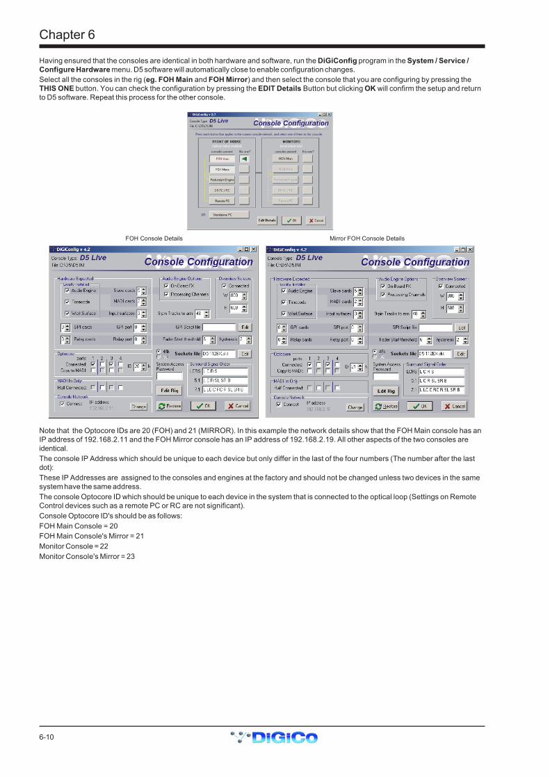
6-10
Chapter 6
Having ensured that the consoles are identical in both hardware and software, run the DiGiConfig program in the System / Service /Configure Hardware menu. D5 software will automatically close to enable configuration changes.Select all the consoles in the rig (eg. FOH Main and FOH Mirror) and then select the console that you are configuring by pressing theTHIS ONE button. You can check the configuration by pressing the EDIT Details Button but clicking OK will confirm the setup and returnto D5 software. Repeat this process for the other console.
FOH Console Details Mirror FOH Console Details
Note that the Optocore IDs are 20 (FOH) and 21 (MIRROR). In this example the network details show that the FOH Main console has anIP address of 192.168.2.11 and the FOH Mirror console has an IP address of 192.168.2.19. All other aspects of the two consoles areidentical.The console IP Address which should be unique to each device but only differ in the last of the four numbers (The number after the lastdot):These IP Addresses are assigned to the consoles and engines at the factory and should not be changed unless two devices in the samesystem have the same address.The console Optocore ID which should be unique to each device in the system that is connected to the optical loop (Settings on RemoteControl devices such as a remote PC or RC are not significant).Console Optocore ID's should be as follows:FOH Main Console = 20FOH Main Console's Mirror = 21Monitor Console = 22Monitor Console's Mirror = 23
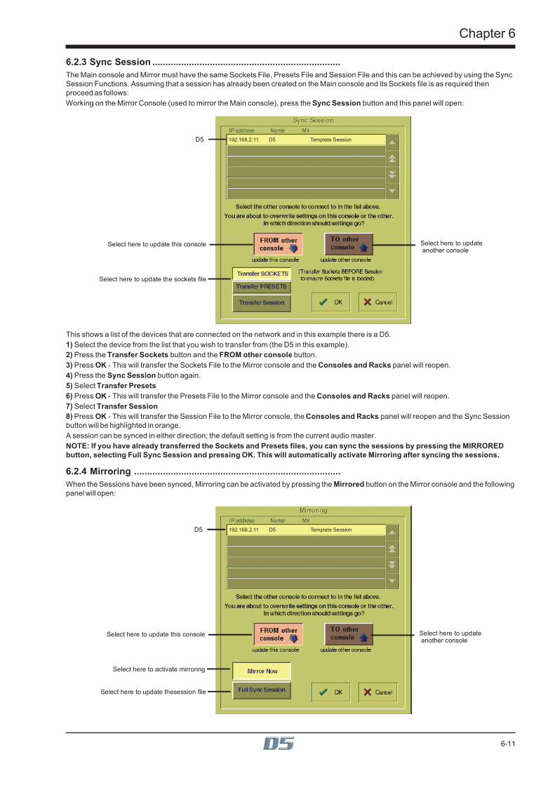
6-11
Chapter 6
6.2.3 Sync Session ........................................................................The Main console and Mirror must have the same Sockets File, Presets File and Session File and this can be achieved by using the SyncSession Functions. Assuming that a session has already been created on the Main console and its Sockets file is as required thenproceed as follows:Working on the Mirror Console (used to mirror the Main console), press the Sync Session button and this panel will open:
D5
Select here to update this console
Select here to update the sockets file
Select here to update another console
192.168.2.11 D5 Template Session
This shows a list of the devices that are connected on the network and in this example there is a D5.1) Select the device from the list that you wish to transfer from (the D5 in this example).2) Press the Transfer Sockets button and the FROM other console button.3) Press OK - This will transfer the Sockets File to the Mirror console and the Consoles and Racks panel will reopen.4) Press the Sync Session button again.5) Select Transfer Presets6) Press OK - This will transfer the Presets File to the Mirror console and the Consoles and Racks panel will reopen.7) Select Transfer Session8) Press OK - This will transfer the Session File to the Mirror console, the Consoles and Racks panel will reopen and the Sync Sessionbutton will be highlighted in orange.A session can be synced in either direction; the default setting is from the current audio master.NOTE: If you have already transferred the Sockets and Presets files, you can sync the sessions by pressing the MIRROREDbutton, selecting Full Sync Session and pressing OK. This will automatically activate Mirroring after syncing the sessions.
6.2.4 Mirroring ...............................................................................When the Sessions have been synced, Mirroring can be activated by pressing the Mirrored button on the Mirror console and the followingpanel will open:
D5
Select here to update this console
Select here to activate mirroring
Select here to update thesession file
Select here to update another console
192.168.2.11 D5 Template Session

6-12
Chapter 6
1) Select the device from the list that you wish to Mirror from (the D5 in this example).2) Select FROM other console and Mirror Now and then press OK.When the process is complete, the MIRRORED Button will be highlighted in orange as seen below. There will also be a pop up messageto confirm that mirroring has taken place.If you have other devices in your system such as a Remote Controller then this process should be repeated on each device, alwaystransferring sockets, syncing sessions and mirroring From the Main console.
6.2.5 DiGiRack Control .................................................................
Main Console Redundant Engine, Mirror Console or Remote
If the system has been defined as consisting of more than one device, the Consoles & Racks panel will automatically open on boot up orload session.This panel can also be opened from the System menu.If the Ethernet crossover cable or Ethernet switch has been connected, then the Ethernet Connected line should show a green OK lightand not a red cross.The initial state will have no connection between the devices (Independent) or the racks (Isolated) and the panel appears in order toprompt the operator to make the necessary connections.In this state, any gain adjustments made on the console will have no effect as the racks will not be receiving any data.The Main console’s MASTER Audio Outputs Active button will normally be highlighted in orange to show that it is the master responsi-ble for audio processing at this time.The same button on the Mirror should not be highlighted at all.The MADI Rack’s connect states Receive Only and Full Connect are enabled/disabled and set according to the Audio Master active state– an inactive engine cannot output to a MADI rack.When the Main console and the Redundant Engine have been mirrored, the communication with the DiGiRacks should be activated.In a system where there is only a single console and a mirror, on the Main console, press the Full Connect buttons for the Optocore andMADI racks. You will then be required to confirm the action, the session settings will be sent to the racks and the console will have fullcontrol over them.
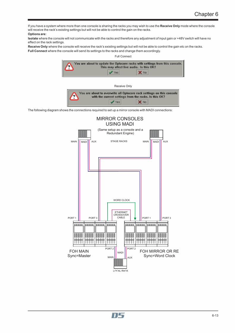
6-13
Chapter 6
If you have a system where more than one console is sharing the racks you may wish to use the Receive Only mode where the consolewill receive the rack’s existing settings but will not be able to control the gain on the racks.Options are:Isolate where the console will not communicate with the racks and therefore any adjustment of input gain or +48V switch will have noeffect on the rack settings.Receive Only where the console will receive the rack’s existing settings but will not be able to control the gain etc on the racks.Full Connect where the console will send its settings to the racks and change them accordingly.
Receive Only
Full Connect
The following diagram shows the connections required to set up a mirror console with MADI connections:
MIRROR CONSOLES USING MADI
FOH MIRROR OR RESync=Word Clock
FOH MAINSync=Master
STAGE RACKS
(Same setup as a console and aRedundant Engine)
LOCAL RACK
AUX
PORT 3 PORT 3PORT 1
WORD CLOCK
ETHERNETCROSSOVER
CABLEPORT 1
PORT 2 PORT 2
MAIN MAINAUX
MADI
MADI MADI
MAIN AUX
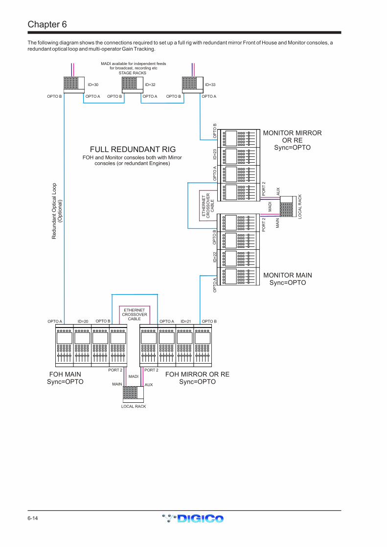
6-14
Chapter 6
The following diagram shows the connections required to set up a full rig with redundant mirror Front of House and Monitor consoles, aredundant optical loop and multi-operator Gain Tracking.
FULL REDUNDANT RIG
FOH MIRROR OR RESync=OPTO
MONITOR MIRROROR RE
Sync=OPTO
FOH MAINSync=OPTO
MONITOR MAINSync=OPTO
STAGE RACKS
MADI available for independent feedsfor broadcast, recording etc
FOH and Monitor consoles both with Mirrorconsoles (or redundant Engines)
Red
unda
nt O
ptic
al L
oop
(Opt
iona
l)
OPTO AOPTO B OPTO B
ID=30 ID=33ID=32
OPTO BOPTO A OPTO A
LOCAL RACK
OPTO B OPTO BOPTO A
ETHERNETCROSSOVER
CABLEOPTO A
PORT 2 PORT 2
ID=20 ID=21
MADI
MAIN AUX
LOC
AL R
ACK
OPT
O B
OPT
O B
OPT
O A
ETH
ERN
ETC
RO
SSO
VER
CAB
LEO
PTO
A
POR
T 2
POR
T 2
ID=2
2ID
=23
MAD
I
MAI
NAU
X

6-15
Chapter 6
6.3 PC Remote ControlIf D5 software is run on a standalone PC or laptop, sessions may be prepared off line or the PC can be used to remote control a console.Input channel windows are run in separate moveable windows for easier access on smaller screens. The Overview Screen and a BankSwitches window are also displayed. Channel and Master LCD buttons appear at the bottom of each screen.A PC can also be used as a Remote Control device for the console and this is set up in a similar way to a Mirror console.
6.3.1 Remote PC Setup .................................................................DiGiCo recommend that the Remote PC is running under Windows ME or XP and that the operator has sufficient knowledge of theoperating system to change IP addresses and set up a standard network connection.Note: With Windows XP the built in Firewall should be disabled as this may cause operational problems.1) An Ethernet Crossover cable (not a standard CAT5 cable) should be connected between the Main console and the Remote PC orboth devices should be connected to an Ethernet switch if there is a third device in the system eg. a Mirror console or Redundant Engine.2) Set the Remote PC's IP address to 192.168.2.xxx (where xxx is a number between 0 and 255 that is unique within the system).The IP address can be checked by opening the System/Service/Configure Hardware panel, pressing all the buttons for the devicesthat are present in the system (eg FOH Main and Remote PC) and then selecting the This One button for the device that you are workingon. Then press Edit Details and the IP address can be seen in the bottom left of the panel.
1
2 3
4
IP Address for “This One”3) Repeat his process for the other device(s) and start the D5 application on all of them.As the system has been defined as consisting of more than one device, the Consoles & Racks panels should open automatically and theEthernet Connected line should show a green OK light and not a red cross.4) Proceed with Syncing the Sockets, Presets and Session files and then Mirroring as described in the previous sections on Mirrorconsoles (6.2.3 and 6.2.4).
6.3.2 Remote PC Operation ..........................................................To use the software with a mouse and keyboard the following functions are necessary:Left mouse click on a non active window makes it active.Right mouse click on a window functions as a screen touch.Double click in the grey area around the LCD buttons to change their function.Left mouse click on a switch to turn it on or off.Hold down left mouse button and drag to adjust rotaries and faders.Ctrl 1 to 6 = bank buttons 1 to 6 on the upper master.Shift 1 to 6 = bank buttons 1 to 6 on input surface 1.Up/Down (arrows) = scroll rotary assignment on all input screens.Page Up/Down acts as the screen scroll button in the Master section.The Shift key acts as the All button for all surfaces.
Running on a laptop or desktop PC, a single knob and button device can be connected to the RS232 COM port and used to alter control-lers on the PC screen under the mouse cursor. A new entry in the D5.ini file is required for this:COMport = n, where n = 1 or 2 for COM1 or COM2, or the default of 0 for off (don’t open COM port in case something else is connected).
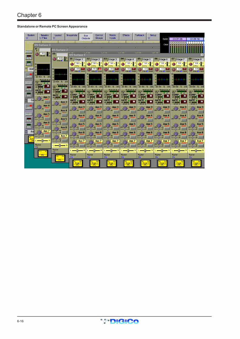
6-16
Chapter 6
Standalone or Remote PC Screen Appearance

7-1
Chapter 7
Chapter 7Troubleshooting

Chapter 7
7-2
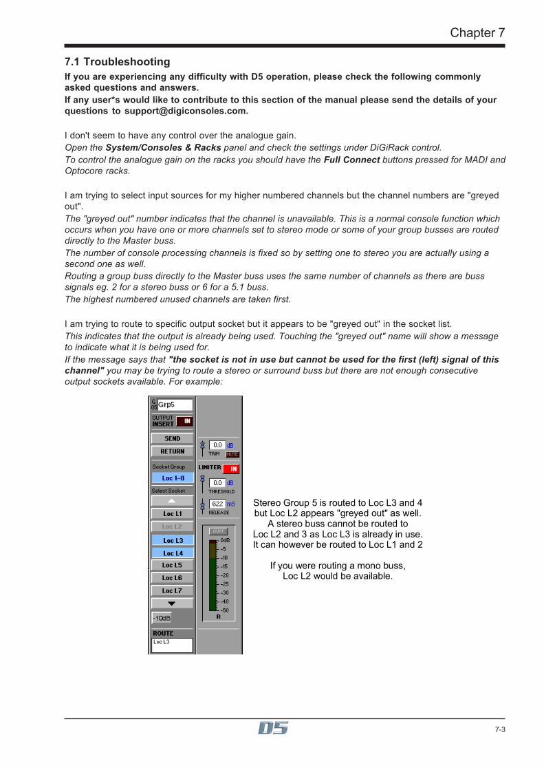
7-3
Chapter 7
7.1 TroubleshootingIf you are experiencing any difficulty with D5 operation, please check the following commonlyasked questions and answers.If any user*s would like to contribute to this section of the manual please send the details of yourquestions to [email protected].
I don't seem to have any control over the analogue gain.Open the System/Consoles & Racks panel and check the settings under DiGiRack control.To control the analogue gain on the racks you should have the Full Connect buttons pressed for MADI andOptocore racks.
I am trying to select input sources for my higher numbered channels but the channel numbers are "greyedout".The "greyed out" number indicates that the channel is unavailable. This is a normal console function whichoccurs when you have one or more channels set to stereo mode or some of your group busses are routeddirectly to the Master buss.The number of console processing channels is fixed so by setting one to stereo you are actually using asecond one as well.Routing a group buss directly to the Master buss uses the same number of channels as there are busssignals eg. 2 for a stereo buss or 6 for a 5.1 buss.The highest numbered unused channels are taken first.
I am trying to route to specific output socket but it appears to be "greyed out" in the socket list.This indicates that the output is already being used. Touching the "greyed out" name will show a messageto indicate what it is being used for.If the message says that "the socket is not in use but cannot be used for the first (left) signal of thischannel" you may be trying to route a stereo or surround buss but there are not enough consecutiveoutput sockets available. For example:
Stereo Group 5 is routed to Loc L3 and 4but Loc L2 appears "greyed out" as well.
A stereo buss cannot be routed toLoc L2 and 3 as Loc L3 is already in use.It can however be routed to Loc L1 and 2
If you were routing a mono buss,Loc L2 would be available.
Chapter 7
7-4
The console has crashed but when it tries to recover the session there is still a problem.The session file may have become corrupted. Reload the D5 software whilst holding the keyboard"Shift" key. A Recover and Restart panel will appear which provides different reboot options.Note: If you hold the Shift key while Windows is rebooting the Surfaces.exe program will notstart and the console will not function correctly. Therefore, load the D5 software then Quit ToWindows using the System / Service Menu and then load the D5 software again whilst holdingthe Shift key.
I have an input source selected for a channel but there is no audible signal.Check that the channel insert is not switched on. If it is switched on but no insert return signal is se-lected then there will be no audible signal in that channel.The channel high and low pass filters are not having any effect on my audio signal.These filters have no effect on internal signals as they are preprocessing.Internal signals consist of:1) Talkback mics, tone and noise generators (Misc Input Group).2) Buss results used as input sources (any input source name preceded by the symbol ~).3) Returns from the optional internal effects module (Effects Input Group).
I do not seem to have as many Channel Sends available as I should.The number of Channel Sends available can be seen in the Diagnostics panel under the System menu.They are used by Direct Outputs, Channel Insert Sends and the internal Effects module.If you are using the internal Effects module:2 Channel Sends will be used for each stereo effect.If FX5 and FX6 are set to Output Processing, anything between 4 (2 x stereo masters) and 16 (2 x 7.1masters) Channel Sends will be used.
How do I tell if a channel is stereo or mono when the input screen is in its standard view?Stereo channels have two on-screen meters and there is also an "s" below the channel number at thetop of the screen.
How can I change the Pre/Post setting for a single auxiliary send?To change this setting, use the button beneath the auxiliary send control but make sure that the send isset to minimum. Using the same button with the send turned up will switch the auxiliary on and off.
I cannot see the Width control for a stereo channel on the screen.Use the Screen Scroll buttons to move the highlighted line down. The Width control is in the last positionafter the Pan control.
I want to trigger a noise gate with an external source but when I press the Key button, the key sourcepanel doesn't appear.Check that you haven't selected a dynamics configuration which includes filters. The external trigger isonly available for the first dynamics configuration where the filters are not used.
The audio is sometimes interrupted when I use the channel EQ.Switching the Channel LPF or HPF Filters in will briefly interrupt the audio in that channel.

Index
IndexSymbols3 band compression 5-79-pin 4-279-pin Eavesdrop 4-27
AAES/EBU 4-29AFL 4-10ALL Button 2-17All Channels 4-23Assign Faders To Banks 4-17Assign Rotary 1-17Assign Sends To Faders 3-5, 4-16Assign Sends To Rotaries 3-5Assign Switch 1-16, 1-17Assignable Rotary 2-4Assigning a Channel 2-5Auto Sequence 4-24Aux Pre / Post 2-12Aux Send > Faders 2-19Auxiliaries 1-16, 2-12Auxiliary Buss Control 3-5
BBuild Bank 4-18Build Gangs 2-20Buss Outputs Display 3-3Buss Signals as Input Sources 3-7
CChannel Assignment 2-3Channel Bank Assign 2-23Channel Banks 2-22Channel Label 2-6Channel LCD Button 1-11, 2-17Channel LCD Function 1-12, 2-17Channel Overview 2-26Channel Presets 2-7Channel Scope 4-23Channel Sends 7-4Clear All 3-5Clear Assignment 2-23Clearing Settings 4-6Compressor 2-10Configure Effects 5-3Connect All 3-5Console Security 1-9, 4-5Consoles & Racks 6-7Control Change 4-26Control Groups 1-18, 4-14Controller Scope 4-23Copy Channels 2-24Copy Levels from Faders 3-5Copy to MADI 4-5Crossfades 4-24Crossover 5-7Curve 1-15, 2-9
DdB Pop-up Readouts 4-4Delay 2-8Delete File 4-7Deleting a Snapshot 4-22Destructive Solo In Place 4-10DiGiConfig 6-3Digital Trim 6-7Direct Outputs 2-15Duplicate Channel 2-25Dynamics 1-16, 2-10Dynamics Linking 2-11Dynamics Presets 2-11
EEDIT Configuration Details 6-3Editing Multiple Snapshots 4-21Effects and Auxiliaries 5-4Effects and Routing 5-4Effects Control 5-6Enable Gain Tracking 6-7EQ 1-15Equaliser 2-8Ethernet Connected 1-9Ethernet Crossover cable 6-9Exclude 4-23External Screens 2-21External Sync 4-28, 4-29
FFader Assigns Channel 2-18Fader Bank 2-3Fire Next After 4-24FOH and Monitors Setup 6-3Frame Rate 4-27Full Connect 1-9
GGain 2-8Gain Tracking 6-7Gain Tracking and Snapshots 6-8Ganging 2-20Gate 2-10Gate Key 2-10Graphic EQ 5-8Greyed out 7-3Group Buss Control 3-5Group Routing 2-15
HHeadphones 3-7Hipass / Lopass Filters 2-9

Index
IIndependent) 1-9Input Balance 2-7Input Meters 2-4Input Module 2-6Input Normalising 5-6Input Screen 2-4Input Source 1-10Insert 4-20Insert On/Off 3-3Insert Routing 2-16Internal Signals 7-4Internal Sync 4-28Isolate 1-9
JJoystick 2-13
KKey Solo 2-11
LLabel 3-5Layout 2-21Level Trim 3-6Limiter 3-6Limiter In/Out 3-3Limiting 5-7Listen to Copied MADI 4-5Live mode 4-5Load Presets 4-8Load Session 4-7Locate To 4-24
MMachine Control 4-27Main Buss Mode 4-6Main Channels Dynamics 5-7Main EQ 5-7Make Masters Safe 4-15Master Audio Outputs Active 1-9Master Banks 2-22, 2-23Master Fader Banks 1-19Master LCD Function Button 4-15Master Screen Status Display 4-3Master Section Meters 4-11Master Snapshot 4-20Matrix 3-8Matrix Inputs 1-17, 3-8Matrix Send 1-17, 3-8Merge 4-8Meter Ballistics 4-11Meter Bridge 4-11Meter Button 4-11Meter Monitors 4-11Meter Selected Busses 4-11MIDI (MTC) 4-27MIDI Machine Control 4-27MIDI Patches 4-25
MIDI Sequence Files 4-26"Misc" Signal Group 2-6Monitor Delay 4-10Monitor Master 4-10Monitor Mute 4-11Monitor Output 4-10Monitoring 4-9Move Channels 2-24Move Intervening 2-24Moving a Snapshot 4-22MS Decode 2-7
NNew Project 4-7New Session 4-6Note Off 4-25Note On 4-25
OOff-line 4-27On Screen Touch Keyboard 4-4Only Display Name 2-18Other Effects 5-3Output Channel Routing 3-6Output Insert 3-7, 5-5, 5-9, 5-10Output Normalising 5-6Output Processing (FX5 and FX6) 5-3Over 3-3Overview 2-21Overview Setup 2-22
PPan 2-13Pan / Aux Module 2-12Peak Hold 4-11PFL 4-10Phantom Power 2-7Phase 2-8Play From 4-24Play To 4-24Post Fader Option 4-15PPM Default 4-11Preset Pan Positions 2-13Presets 4-8Preview 4-23Processing Channels 5-8Processors 5-8Program Change 4-26
QQuit To Windows 4-4
RReceive Only 1-9Recovery 4-12Redundant Mirror Console 6-9, 6-11, 6-12, 6-
15Redundant Optical Loop 6-9Relative 4-21Relative Snapshot 4-20
Index
Relays 4-24Rename 4-7Rename File 4-7Renaming a Snapshot 4-22Replacing a Snapshot 4-21Restart 4-12Return 2-16Reverb (FX1) 5-3Round to whole dBs 4-4Route to a Direct Output 1-12Route to a Group 1-12Routing 2-14Routing Busses To Outputs 1-13
SSafe 2-18Sample Rate 4-29Sample Rate Convertors 4-29Save As New File 1-14, 4-8Save Presets 4-8Save Session 1-14, 4-8Save Startup Session On Exit 4-4Scope 2-24Screen Brightness 4-4Screen Scroll 1-16, 2-4, 2-12Scrolling the Master Screen 3-3Select Signal 2-6Send 2-16Send Gain 2-16Sessions Menu 4-6Set All 1-17, 3-8Set all Input Direct Sends 4-6Set Levels OFF 3-5Set Levels to 0dB 3-5Signal Group 2-6Single 4-10SIP 4-10SMPTE (LTC) 4-27Snapshot Layouts 4-22Snapshot Scope 4-23Snapshot Timing 4-24Snapshot Undo 4-22Snapshots 4-19Snapshots and MIDI 4-25Solo 1-11, 2-17Solo 1 or 2 4-10Solo 2 Assign 4-10Solo Assigns Channel 2-18Solo Asssigns Aux To Faders 4-16Solo Clear 4-11Solo Options 1-20Solo Safe 4-11Solo Trim Level 4-11Status LED 1-16Stereo 1-11Stereo Channel 2-6Stereo Link 2-11Sub 2-13Sub Channel Dynamics 5-7Sub Channel EQ 5-7
Surface Label Display Brightness 4-4Surround Panning 2-13Swap (Reverse) Left and Right Signals 2-7Swap Channels 2-24Switch All 3-5SYNC CONSOLE 6-9Sync Sockets Files 6-9Synchronisation
Digital 4-28System Menu 4-4System Options 4-4System Shut Down 4-4System Status Indicators 4-4
TTalkback 4-12Talkback Mic 4-13Talkback Mixer 4-14Talkback Presets 4-14Talkback Setup 4-13Template Session 1-10Timecode Output 4-27Timecode Source 4-27To Master 3-5Touch To Fire 4-21Track On/Off 6-7Transfer Presets 6-11Transfer Session 6-11Transfer Sockets 6-11
UUnassign Faders From Banks 4-18Unattended 4-5Undo / Redo 2-17Update Master 4-21USB Data Port 4-8
VVideo Sync 4-29Video Sync Lock 4-27VU Default 4-11
WWhite Light Illumination Brightness 4-4Width 7-4Word Clock 4-29Worksurface Channels 2-3

Index


