Embed Size (px)
Citation preview
Project no. 265863
ACCESS Arctic Climate Change, Economy and Society
Instrument: Collaborative Project Thematic Priority: Ocean.2010-1 “Quantification of climate change impacts on economic
sectors in the Arctic”
D4.31 – Report on rescue and evacuation systems
Due date of deliverable: 30/09/2013
Actual submission date: 11/10/2013
Used Person/months: 12
Start date of project: March 1st, 2011 Duration: 48 months
Organisation name of lead contractor for this deliverable: IMPaC
IMPaC Doc. No: 1874-00-IHH-RPT-RD-00004-000 IMPaC Rev.: B
Project co-funded by the European Commission within the Seventh Framework Programme (2007-2013)
Dissemination Level PU Public X
PP Restricted to other programme participants (including the Commission Services)
RE Restricted to a group specified by the consortium (including the Commission Services)
CO Confidential, only for members of the consortium (including the Commission Services)

Deliverable report: D4.31 – Report on rescue and evacuation systems
Date: 31/05/2013 1874-00-IHH-RPT-RD-00004-000 Revision: B Page 2 of 41
Revision Code Revision Date Revision Status Prep. DIC IDC IMPaC
Appr. IMPaC Client
A 20-Sep-2013 Issued for Review JMY SH BER
B 16-Jan-2014 Comments implemented JMY SH BER
Abstract
Aim of work package WP4.3 within ACCESS is the assessment of existing rescue and evacuation crafts and vessels as well as the suggestion of alternative concepts based on future ice conditions and identification of requirements for adjustment to account for the special situation in the Arctic
Objective 4.3 was met by assessing presently available evacuation and rescue-systems considering the future climate conditions under which evacuation and rescue operations will need to be carried out in the Arctic.
Information on ice extent, ice thickness, ice coverage, floe size, ridge density (number/unit length) and occurrence of hummock and icebergs coming from WP1 and shipping routes determined in WP2 are influencing the evacuation procedures, type of rescue vessels and evacuation crafts.
IMPaC concentrated on evacuation systems for stationary (fixed) offshore platforms, while HSVA focused on lifeboats and rescue equipment for moving vessels in cooperation with WP1, WP2 and WP3, as described in this Report. Also land based infrastructure as they are part of any suitable Emergency, Evacuation and Rescue concept (for the Arctic) are considered.
(Task leader: IMPaC (Hamburg), partner: HSVA (Hamburg)).
Deliverable report: D4.31 – Report on rescue and evacuation systems
Date: 31/05/2013 1874-00-IHH-RPT-RD-00004-000 Revision: B Page 3 of 41
Document Check and Verification Record for Current Revision
Prepared by Myland, Johannes
Name, first name Signature Date
Discipline Internal Check (DIC) by Hoog, Dr. Sven
Name, first name Signature Date
Inter Discipline Check (IDC) by
Name, first name Signature Date
IMPaC Approval by Berger, Joachim
Name, first name Signature Date
Client Approval by
Name, first name Signature Date
Revision Tracking
Revision Code Description
IMPaC Client A Issued for Review
B Comments implemented
HOLD Record
Description of HOLD Chapter
References
Ref. No. Reference Description Refer list under Chapter 8 in this Report
Deliverable report: D4.31 – Report on rescue and evacuation systems
Date: 31/05/2013 1874-00-IHH-RPT-RD-00004-000 Revision: B Page 4 of 41
TABLE OF CONTENTS
1 INTRODUCTION ................................................................................................................................... 6 2 OBJECTIVE .......................................................................................................................................... 7 3 ABBREVIATIONS ................................................................................................................................. 8 4 STANDARDS ........................................................................................................................................ 9 5 ENVIRONMENTAL CONDITIONS ...................................................................................................... 10
5.1 ICE CONDITIONS ....................................................................................................................... 11 5.2 SNOW ......................................................................................................................................... 11 5.3 ATMOSPHERIC AND SEA SPRAY ICING ................................................................................. 11 5.4 COLD TEMPERATURES ............................................................................................................ 12 5.5 WAVES AND WIND IN OPEN WATER ...................................................................................... 12 5.6 LIGHTING CONDITIONS ............................................................................................................ 12 5.7 SNOW, RAIN AND FOG ............................................................................................................. 12
6 AVAILABLE TECHNOLOGY MODULES........................................................................................... 13 6.1 OVERVIEW ................................................................................................................................. 13 6.2 ESCAPE, EVACUATION AND RESCUE FROM STATIONARY PLATFORMS / VESSELS ..... 14
6.2.1 Direct and Dry Evacuation ...................................................................................................... 14 6.2.1.1.1 Helicopter ............................................................................................................................. 14 6.2.1.1.2 Support Vessel ..................................................................................................................... 15 6.2.2 Indirect or Semi-Dry Evacuation ............................................................................................. 15 6.2.3 Lifeboats .................................................................................................................................. 16 6.2.3.1.1 TEMP(A)SC .......................................................................................................................... 16 6.2.3.1.2 Ice Breaking Emergency Evacuation Vessel ....................................................................... 18 6.2.3.1.3 Totally Enclosed Motor Propelled Arctic Survival Craft........................................................ 18 6.2.3.1.4 Boat-In-A-Box Davit ............................................................................................................. 18 6.2.3.1.5 Ice Strengthened Lifeboat .................................................................................................... 19 6.2.4 Liferafts .................................................................................................................................... 19 6.2.5 Tracked amphibious vehicle .................................................................................................... 19 6.2.6 Hovercraft ................................................................................................................................ 20 6.2.7 Archimedean Screw Tractor .................................................................................................... 20 6.2.8 Wet evacuation ........................................................................................................................ 20 6.2.9 Concept of new lifesaving appliances ..................................................................................... 21 6.2.10 Discussion of results of the case studies ................................................................................ 21 6.2.11 Design considerations for a new Launch and Recovery System (LARS) ............................... 21
6.3 ESCAPE, EVACUATION AND RESCUE FROM MOBILE VESSELS / SHIPS .......................... 22 6.3.1 General .................................................................................................................................... 22 6.3.2 Assessment of different EER-Systems ................................................................................... 22 6.3.3 Concept of new lifesaving appliances ..................................................................................... 23 6.3.3.1 Conventional lifeboat ............................................................................................................ 24 6.3.3.1.1 Concept 1: Ball-shaped floater ............................................................................................. 25 6.3.3.1.2 Concept 2: Conical-shaped floater ....................................................................................... 26
Deliverable report: D4.31 – Report on rescue and evacuation systems
Date: 31/05/2013 1874-00-IHH-RPT-RD-00004-000 Revision: B Page 5 of 41
6.4 ESCAPE, EVACUATION AND RESCUE SEEN AS SYSTEM – LAND BASED EER INFRASTRUCTURE ................................................................................................................... 28
7 CONCLUSION ..................................................................................................................................... 30 8 REFERENCES .................................................................................................................................... 31
ANNEX
Images, Illustrations ........................................................................................................... 34 Annex A
INDEX OF FIGURES
Figure 5-1: Extreme weather conditions for offshore areas of the Northern Sea Route within the Arctic Circle (Source: Internet) ..................................................................................... 10
Figure 6-1: EER framework (source: Canadian Performance-Based Standards) ............................... 13 Figure 6-2: Matrix for assessment of different EER-Systems for work in Arctic conditions ................. 23 Figure 6-3: Matrix for assessment of different EER-Systems indifferent ice conditions ...................... 23 Figure 6-4: Ball-shaped floater [plan view (left); side view (right)] ....................................................... 25 Figure 6-5: Lever arm curve of the ball-shaped floater ........................................................................ 26 Figure 6-6: Conical-shaped floater ....................................................................................................... 27 Figure 6-7: Main parameters of the conical-shaped floater.................................................................. 27 Figure 6-8: Lever arm curve of the conical-shaped floater................................................................... 28 Figure 8-1: Ice built-up and manual de-icing of a ship’s deck .............................................................. 34 Figure 8-2: Concrete drilling and production platform Lunskoye A in drifting ice (note the
marked free fall rescue boats) ........................................................................................... 34 Figure 8-3: Massive ice built-up at a shallow water production platform under influence of ice
drift (Caspian Sea) ............................................................................................................. 35 Figure 8-4: Ice management for shallow water drilling / production platform Sunkar by means
of ice protection structures and ice breaking vessels (Caspian Sea) ................................ 35 Figure 8-4: Double acting tanker during backward travel through ice covered water (note the
marked free fall rescue boat) ............................................................................................. 36 Figure 8-5: Ice management with heavy duty ice breakers.................................................................. 36 Figure 8-6: Personnel transfer / evacuation via Helicopter .................................................................. 37 Figure 8-7: Evacuation from offshore platforms via fall net for single persons and liferafts ................ 37 Figure 8-8: Cannister type liferafts on a vessel (left); liferafts launched to sea by crane (right) .......... 37 Figure 8-9: Rubber tracked vehicles for onshore personnel evacuation .............................................. 38 Figure 8-10: Hovercraft vehicles for personnel evacuation from onshore and offshore facilities .......... 38 Figure 8-11: Ice Breaking Emergency Evacuation Vessel (IBEEV) for personnel evacuation in
massive ice conditions ....................................................................................................... 38 Figure 8-12: Boat-in-a-box (source: nadiro.com) ................................................................................... 39 Figure 8-13: A 1/7 scale model of the TIT-800 (source: Offshore Marine) ............................................ 39 Figure 8-14: ARKTOS crafts for personnel evacuation in drifting ice conditions ................................... 40 Figure 8-15: Steps of operation of the new evacuation concept using specially designed
Hovercraft and LARS (IMPaC, Ref. [7]) ............................................................................. 40 Figure 8-16: Technical drawing of the lifeboat 20TECB (Source: Umoe Schat-Harding) ...................... 41
Deliverable report: D4.31 – Report on rescue and evacuation systems
Date: 31/05/2013 1874-00-IHH-RPT-RD-00004-000 Revision: B Page 6 of 41
1 INTRODUCTION
The Arctic is engaged in a deep climatic evolution. This evolution is quite predictable at short (year) and longer scales (several decades), but it is the decadal intermediate scale that is the most difficult to predict. This is because the natural variability of the system is large and dominant at this scale, and the system is highly non-linear due to positive and negative feedback between sea ice, the ocean and atmosphere.
Already today, due to the increase of the GHG concentration in the atmosphere and the amplification of global warming in the Arctic, the impacts of climate change in the region are apparent, e.g. in the reduction in sea ice, in changes in weather patterns and cyclones or in the melting of glaciers and permafrost. It is therefore not surprising that models clearly predict that Artic sea ice will disappear in summer within 20 or 30 years, yielding new opportunities and risks for human activities in the Arctic.
This climatic evolution is going to have strong impacts on both marine ecosystems and human activities in the Arctic. This in turn has large socio-economic implications for Europe. ACCESS will evaluate climatic impacts in the Arctic on marine transportation (including tourism), fisheries, marine mammals and the extraction of hydrocarbons for the next 20 years; with particular attention to environmental sensitivities and sustainability.
These meso-economic issues will be extended to the macro-economic scale in order to highlight trans-sectoral implications and provide an integrated assessment of the socio-economic impact of climate change. An important aspect of ACCESS, given the geostrategic implication of Arctic state changes, will be the consideration of Arctic governance issues, including the framework UNCLOS (United Nations Convention on the Law of the Sea).
ACCESS dedicates a full work package to integrate Arctic climate changes, socio-economic impacts and Arctic governance issues.
Comments to Revision B:
A list with the most important results from this assessment has been added to chapter 7 (Conclusions).
Deliverable report: D4.31 – Report on rescue and evacuation systems
Date: 31/05/2013 1874-00-IHH-RPT-RD-00004-000 Revision: B Page 7 of 41
2 OBJECTIVE
Main objective of work package 4.3 is to assess and describe existing escape, evacuation and rescue (EER) systems and to suggest alternative concepts based on future ice conditions where appropriate and to identify requirements for adjustment to account for the special situation in the Arctic.
Objective of this Report is to describe technical aspects of existing EER systems for fixed offshore platforms (IMPaC contribution) as well as for moving vessels in Arctiv waters (HSVA contribution). Both parts need dedicated land based infrastructure to work properly in terms of safety and sustainability. Thus, a study has been carried out by IMPaC analysing the current available and further required infrastructure of a land based backbone of EER concepts for offshore Arctic application.
Input concerning expected ice extent, ice thickness, ice coverage, floe size, ridge density (number/unit length) and occurrence of hummock and icebergs coming from WP1 and shipping routes determined in WP2 are gathered in cooperation with WP1, WP2 and WP3 of ACCESS.
Deliverable report: D4.31 – Report on rescue and evacuation systems
Date: 31/05/2013 1874-00-IHH-RPT-RD-00004-000 Revision: B Page 8 of 41
3 ABBREVIATIONS
ACCESS Arctic Climate Change, Economy and Society
ACV Air Cushioned Vehicle
E+P Exploration and Production
EER Escape, Evacuation and Rescue
FLNG Floating Liquefied Natural Gas
FPSO Floating (Oil) Production, Storage and Offloading
FPU Floating Production Unit
IBEEC Ice Breaking Emergency Evacuation Craft
IBEEV Ice Breaking Emergency Evacuation Vessel
ISL Ice Strengthened Lifeboat
ISL Ice Strengthened Lifeboat
ISO International Standardization Organization
LARS Launch and Recovery System
MPa Mega Pascal
OPEX Operational Expenditures
PPE Personal Protective Equipment
PROD Preferred Orientations and Displacement
TEMPASC Totally Enclosed Motor Propelled Arctic Survival Craft
TEMPSC Totally Enclosed Motor Propelled Survival Craft
TOES TEMPSC Orientation and Evacuation System
WP Work package
Deliverable report: D4.31 – Report on rescue and evacuation systems
Date: 31/05/2013 1874-00-IHH-RPT-RD-00004-000 Revision: B Page 9 of 41
4 STANDARDS
The following standards have been referenced for the assessment:
• ISO13628-X (all parts), Petroleum and natural gas industries - Subsea developments, International Organization for Standardization, 2005 and younger
• ISO 19901 (all parts), Petroleum and natural gas industries — Specific requirements for offshore structures
• ISO 19906, Petroleum and natural gas industries - Arctic offshore structures
Deliverable report: D4.31 – Report on rescue and evacuation systems
Date: 31/05/2013 1874-00-IHH-RPT-RD-00004-000 Revision: B Page 10 of 41
5 ENVIRONMENTAL CONDITIONS
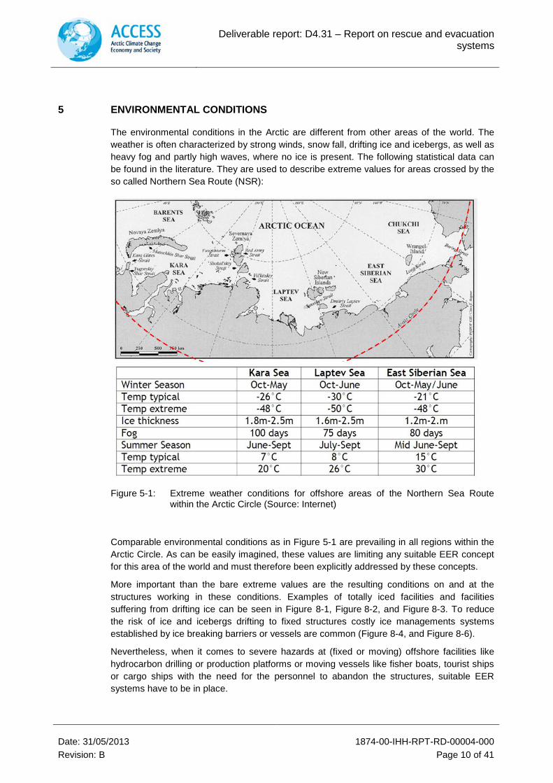
The environmental conditions in the Arctic are different from other areas of the world. The weather is often characterized by strong winds, snow fall, drifting ice and icebergs, as well as heavy fog and partly high waves, where no ice is present. The following statistical data can be found in the literature. They are used to describe extreme values for areas crossed by the so called Northern Sea Route (NSR):
Figure 5-1: Extreme weather conditions for offshore areas of the Northern Sea Route within the Arctic Circle (Source: Internet)
Comparable environmental conditions as in Figure 5-1 are prevailing in all regions within the Arctic Circle. As can be easily imagined, these values are limiting any suitable EER concept for this area of the world and must therefore been explicitly addressed by these concepts.
More important than the bare extreme values are the resulting conditions on and at the structures working in these conditions. Examples of totally iced facilities and facilities suffering from drifting ice can be seen in Figure 8-1, Figure 8-2, and Figure 8-3. To reduce the risk of ice and icebergs drifting to fixed structures costly ice managements systems established by ice breaking barriers or vessels are common (Figure 8-4, and Figure 8-6).
Nevertheless, when it comes to severe hazards at (fixed or moving) offshore facilities like hydrocarbon drilling or production platforms or moving vessels like fisher boats, tourist ships or cargo ships with the need for the personnel to abandon the structures, suitable EER systems have to be in place.
Deliverable report: D4.31 – Report on rescue and evacuation systems
Date: 31/05/2013 1874-00-IHH-RPT-RD-00004-000 Revision: B Page 11 of 41
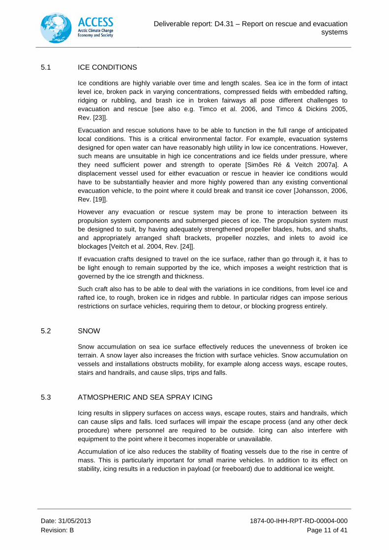
5.1 ICE CONDITIONS
Ice conditions are highly variable over time and length scales. Sea ice in the form of intact level ice, broken pack in varying concentrations, compressed fields with embedded rafting, ridging or rubbling, and brash ice in broken fairways all pose different challenges to evacuation and rescue [see also e.g. Timco et al. 2006, and Timco & Dickins 2005, Rev. [23]].
Evacuation and rescue solutions have to be able to function in the full range of anticipated local conditions. This is a critical environmental factor. For example, evacuation systems designed for open water can have reasonably high utility in low ice concentrations. However, such means are unsuitable in high ice concentrations and ice fields under pressure, where they need sufficient power and strength to operate [Simões Ré & Veitch 2007a]. A displacement vessel used for either evacuation or rescue in heavier ice conditions would have to be substantially heavier and more highly powered than any existing conventional evacuation vehicle, to the point where it could break and transit ice cover [Johansson, 2006, Rev. [19]].
However any evacuation or rescue system may be prone to interaction between its propulsion system components and submerged pieces of ice. The propulsion system must be designed to suit, by having adequately strengthened propeller blades, hubs, and shafts, and appropriately arranged shaft brackets, propeller nozzles, and inlets to avoid ice blockages [Veitch et al. 2004, Rev. [24]].
If evacuation crafts designed to travel on the ice surface, rather than go through it, it has to be light enough to remain supported by the ice, which imposes a weight restriction that is governed by the ice strength and thickness.
Such craft also has to be able to deal with the variations in ice conditions, from level ice and rafted ice, to rough, broken ice in ridges and rubble. In particular ridges can impose serious restrictions on surface vehicles, requiring them to detour, or blocking progress entirely.
5.2 SNOW
Snow accumulation on sea ice surface effectively reduces the unevenness of broken ice terrain. A snow layer also increases the friction with surface vehicles. Snow accumulation on vessels and installations obstructs mobility, for example along access ways, escape routes, stairs and handrails, and cause slips, trips and falls.
5.3 ATMOSPHERIC AND SEA SPRAY ICING
Icing results in slippery surfaces on access ways, escape routes, stairs and handrails, which can cause slips and falls. Iced surfaces will impair the escape process (and any other deck procedure) where personnel are required to be outside. Icing can also interfere with equipment to the point where it becomes inoperable or unavailable.
Accumulation of ice also reduces the stability of floating vessels due to the rise in centre of mass. This is particularly important for small marine vehicles. In addition to its effect on stability, icing results in a reduction in payload (or freeboard) due to additional ice weight.
Deliverable report: D4.31 – Report on rescue and evacuation systems
Date: 31/05/2013 1874-00-IHH-RPT-RD-00004-000 Revision: B Page 12 of 41
5.4 COLD TEMPERATURES
Cold air temperature and wind chill have impacts on both personnel and equipment. Protective clothing is required against the effects of cold, but can result in impaired general mobility, impaired dexterity (due to gloves), and obstructed vision and hearing (due to head and face protection). Many of these considerations are generally relevant in cold regions, and require specific attention to details with respect to EER [Simões Ré & Veitch, 2008, Rev. [21]].
Spaces on board require adequate heating and insulation to ensure protection of personnel from cold temperatures and wind chill. These include escape route arrangements, muster areas and embarkation points. Air supply, air quality and condensation are related issues, as such equipment normally has to be effectively sealed to prevent ingress of toxic gas and smoke.
Air temperature and wind chill also influence the design of systems and equipment, because cold temperatures can cause fluids to freeze in various systems and makes them inoperable. Winterization measures, such as insulation, can be used to protect fire mains, cooling and other water piping systems, and hydraulic lines. Starting systems are also exposed to cold temperatures, thus special heaters or batteries should be provided.
Cold air and water temperatures are parameters to be considered for the choice of materials. Special structural design considerations are also required to withstand concentrated ice loads. Finally, the design of equipment that is exposed to the cold should account for the reduced mobility and dexterity of its operators. Classification societies and the IMO have also provided guidance on winterization measures for ships operating in ice covered waters (e.g. IMO Guidelines).
5.5 WAVES AND WIND IN OPEN WATER
Open water conditions may also occur at many sites associated with sea ice cover. Waves and wind give rise to motions on floating installations that can cause sea sickness and reduced mobility on board. With respect to the means of evacuation, high seas and wind reduce the performance of conventional evacuation craft (Simões Ré & Veitch 2007b, Rev. [20]) and can prevent rescue operations.
The survival time in supercooled water is rather short and can quickly lead to hypothermia or drowning.
5.6 LIGHTING CONDITIONS
Low light conditions and long periods of darkness in northern latitudes require that adequate lighting is provided. This includes emergency lighting systems for escape routes, muster stations and embarkation points. The implementation of rescue operations is severely limited by darkness.
5.7 SNOW, RAIN AND FOG
Snow, rain and fog all reduce visibility, sometimes severely, which can impair all stages of EER and endanger personnel.
Deliverable report: D4.31 – Report on rescue and evacuation systems
Date: 31/05/2013 1874-00-IHH-RPT-RD-00004-000 Revision: B Page 13 of 41
6 AVAILABLE TECHNOLOGY MODULES
6.1 OVERVIEW
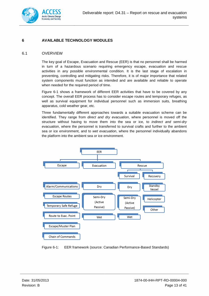
The key goal of Escape, Evacuation and Rescue (EER) is that no personnel shall be harmed in turn of a hazardous scenario requiring emergency escape, evacuation and rescue activities in any possible environmental condition. It is the last stage of escalation in preventing, controlling and mitigating risks. Therefore, it is of major importance that related system components must function as intended and are available and reliable to operate when needed for the required period of time.
Figure 6-1 shows a framework of different EER activities that have to be covered by any concept. The overall EER process has to consider escape routes and temporary refuges, as well as survival equipment for individual personnel such as immersion suits, breathing apparatus, cold weather gear, etc.
Three fundamentally different approaches towards a suitable evacuation scheme can be identified. They range from direct and dry evacuation, where personnel is moved off the structure without having to move them into the sea or ice, to indirect and semi-dry evacuation, where the personnel is transferred to survival crafts and further to the ambient sea or ice environment, and to wet evacuation, where the personnel individually abandons the platform into the ambient sea or ice environment.
Figure 6-1: EER framework (source: Canadian Performance-Based Standards)
Deliverable report: D4.31 – Report on rescue and evacuation systems
Date: 31/05/2013 1874-00-IHH-RPT-RD-00004-000 Revision: B Page 14 of 41
6.2 ESCAPE, EVACUATION AND RESCUE FROM STATIONARY PLATFORMS / VESSELS
Several studies have been conducted in order to evaluate suitable evacuation systems in ice-infested waters: Some referring general locations, other referring to specific areas. In the following existing or commonly used evacuation methods, which might be modified to meet Arctic specific requirements, such as ice, remoteness, lack of infrastructure, etc. are assessed.
Apart from commonly used evacuation systems some new concepts that have been specifically designed for ice conditions are also briefly introduced. Those include:
• Boat-In-A-Box Davit • Hovercraft • AST/TIT800 Archimedean Screw Vessel • Seascape Life Rescue Craft • Totally Enclosed Motor Propelled (Arctic) Survival Craft (TEMP(A)SC) • Ice Strengthened Lifeboat (ISL) • Ganymede Dropped Container
6.2.1 Direct and Dry Evacuation
Generally, the direct and dry evacuation is the preferred and primary means of evacuation. It means to move the people directly off the platform without having to transfer them into the surrounding sea or ice conditions. It is also used as precautionary means of evacuation, which means, that the personnel is removed from the installation prior to an uncontrolled or escalating incident that can otherwise dictate an emergency situation.
Direct and dry evacuation includes using of helicopters or support vessels. More unconventional and site specific options include bridges to other platforms or tunnels to shore, if applicable.
6.2.1.1.1 Helicopter
Evacuation options involving helicopters are preferred. They play a major role in most evacuation plans when the evacuation can be performed in a fully controlled manner. Helicopters are preferred when they can operate within a certain distance between the offshore platform and the land base and when a safe approach to the platform is guaranteed (Figure 8-6).
The presence of sea ice around the platform or vessel has little impact on the performance of the helicopter. Operation is restricted by adverse weather conditions such as strong winds, low air temperatures or atmospheric icing. The wind speed limit for a helicopter to operate on a helicopter deck is about 55 to 60 knots, but normal flying operations may be performed at wind speeds with gusts up to 60 knots. The main issue though is visibility. Normal operations require a minimum cloud base of 200 to 300 m and a horizontal visibility of 900m. Also, the hazardous situation on board can prevent the helicopter to safely access the platform. Examples are major on board fires or gas plumes around the facilities.
Noteworthy, the Arctic wind-chill factor near a hovering helicopter can freeze exposed flesh in a matter of seconds. Thus, protective measures must be considered by the personnel.
Deliverable report: D4.31 – Report on rescue and evacuation systems
Date: 31/05/2013 1874-00-IHH-RPT-RD-00004-000 Revision: B Page 15 of 41
Summarising, emergency evacuations can be supported by helicopters, but due to the reasons mentioned above, a secondary evacuation means must be in place.
6.2.1.1.2 Support Vessel
Another direct and dry evacuation approach requires the personnel to leave the platform using transfer systems like slides, chutes, stairways or bridges to a support or standby vessel. In case a support vessel is close to the facility, which can safely approach and keep station close by, this method will be preferred compared to semi-dry or wet evacuation methods. Note that several rules and regulations highly recommend the permanent presence of one or more ice breaking vessels on site (e.g. Germanischer Lloyd). For example, according to federal oil and gas regulations for Canada’s frontier waters a permanent standby vessel is a requirement for hydrocarbon production platforms.
Offloading personnel can be restricted by gas or fire, as well as high waves. Thus, the main issue is the ability of the support vessel to keep station within fairly tight tolerances over the required timeframe to transfer large numbers of people on board. This can be complicated or even precluded in strong winds, high waves or poor visibility. When ice is present, the key issue is the ability of the vessel to keep station in the prevalent ice condition. Ice conditions limiting the use of support vessels include rapid ice drift speeds, significant ice pressure, combined swell and ice, and/or the threat of the support vessel being squeezed against the platform by ice.
Generally, station keeping near a platform surrounded by low to moderate ice concentration or mobile thin or thick ice is much easier for a support vessel than in high ice concentration. Thick, deformed ice such as ice rubble may prevent a support vessel from approaching a platform or from station keeping. Special equipped support vessel with azimuth thrusters might be required to clear off the rubble. Station keeping of a support vessel in high concentration of New Ice or Young Ice does not present a major challenge for moderately powered icebreaking support vessels, but can become challenging in moderate pack ice especially if the ice is thick, deformed, and moving at high speed. It might be impossible in very heavy pack ice.
Note that Icebreakers are expensive to build and to operate due to its excessive fuel consumption when driving in ice. They have an almost round underwater hull shape, specifically designed to break ice, but they usually roll heavily in beam seas, which is not very comfortable for the personnel. Also, when breaking through continuous thick ice constant vibration and noise from jarring against the ice makes the journey uncomfortable with lots of icebreakers.
6.2.2 Indirect or Semi-Dry Evacuation
The indirect or semi-dry evacuation is a secondary means of evacuation, which can be carried out independently of external support. Generally, the people board a survival craft on board the offshore platform, e.g. lifeboat, liferaft, etc., which is then deployed to the ambient sea or to the ice-conditions. The craft then leaves the platform as fast as possible for subsequent pick-up by means of support vessels, e.g. Icebreakers. Currently used survival crafts for offshore evacuation include:
• lifeboats, such as the Totally Enclosed Motor Propelled Survival Craft (TEMPSC) or the Totally Enclosed Motor Propelled Arctic Survival Craft (TEMPASC), which is an enhanced survival craft for ice-covered waters,
• liferaft
Deliverable report: D4.31 – Report on rescue and evacuation systems
Date: 31/05/2013 1874-00-IHH-RPT-RD-00004-000 Revision: B Page 16 of 41
• the purpose-built Ice Breaking Emergency Evacuation Vessel (IBEEV) • ARKTOS craft.
Other concepts for survival crafts have been suggested, ranging from airborne dirigibles to submarine systems, but the shortfalls and practical disadvantages of most of these concepts generally outweighs any benefits that they may offer (Wright, Timco, Dunderdale, & Smith, 2002). A study conducted by Shell (Ref. [6]) included following options amongst others in a detailed feasibility assessment:
• Lifeboat • Ice strengthened lifeboat (ISL) • Medium-sized ice breaking vessel • Small-sized ice-breaking vessel • Air Cushioned Vehicle (ACV) • Airboat • Tracked amphibious vehicle • Archimedean screw vehicle • Deployable temporary refuge • Submarine
Two of the above mentioned concepts were identified as most promising for year-round secondary evacuation, the tracked amphibious vehicle (e.g. ARKTOS craft) and the air cushioned vehicle (or Hovercraft). However, also the Ice Strengthened Lifeboat (ISL) was seen as a possible option, especially as a second type of evacuation mean better suited to rough water conditions instead of ice conditions.
In the following more detailed information is given for the most suitable systems only, as concluded from the mentioned study.
6.2.3 Lifeboats
6.2.3.1.1 TEMP(A)SC
Lifeboats, such as the Totally Enclosed Motor Propelled (Arctic) Survival Craft (TEMP(A)SC), which is the most common type of survival craft that can be found with offshore structures, are usually capable of carrying 50 people or more, are self-propelled, and provide protection from fire, dangerous vapours and gases for a limited period of time. Commonly, they are mounted on fixed davits that overhang the side of the structure and can be launched using various winching arrangements. In open water a free fall launch approach can be used, whereas the presence of ice prohibits any fast descent system. Other systems that place the unit further away from the platform have been developed, such as the Preferred Orientations and Displacement (PROD) System, TEMPSC Orientation and Evacuation System (TOES) and the Seascape systems. Advantages of placing the craft further away from the platform include avoiding “wash back” and bridging grounded rubble ice that may have formed around the structure. A controlled lowering provides the ability that the craft could be suspended slightly above the waterline and finally launched when the ice condition is appropriate in the landing area, e.g. when a thick ice floe passed by and a gap of open water is present.
The PROD system, which may be described as a giant fishing rod, has been demonstrated to work well across a range of open water situations, but its application may be restricted in dynamic ice conditions with high ridge and rubble sails, cold air icing conditions, and when there are mixed ice and swell situations.
Deliverable report: D4.31 – Report on rescue and evacuation systems
Date: 31/05/2013 1874-00-IHH-RPT-RD-00004-000 Revision: B Page 17 of 41
The TOES approach relies on a permanently installed submerged buoy and a cabling arrangement to orient the TEMPSC away from the platform when it is lowered. This approach works in open water conditions, whereas the presence of ice near the waterline, deep draft ice features, icing or cold water and air temperatures would be problematic with the arrangements and may also simply destroy it.
A company based in Newfoundland, Seascape, developed a new launch system, but also an alternative type of lifeboat. The Seascape system is an articulated launching arm, which is lowered on a winch and deploys a yoke mounted craft 20m to 30m away from the platform. It is intended for use in open water, but Seascape has a modified design which can be applied in ice conditions.
Generally, launch mechanisms and the efficiency of basic launch operations are important issues in cold ice-infested waters. The loads are a strong function of the impact velocity and the shape of the bottom of the lifeboat:
• Very high forces can be transmitted to the lifeboat if it is dropped onto a thick sea ice floe;
• The velocity of the impact is critical in determining the load. The forces are considerably reduced with a low impact velocity;
• The shape of the lifeboat can influence the load. Flat-bottomed boats can lead to very high impact loads
For example the Scottish company Survival Craft Inspectorate (SCI) produces crafts which are suitable for installation on passenger and cargo vessels as well as offshore oil & gas platforms.
Features include: • capacities from 25 to 150 persons on board (POB)
• seating for an average body of 82.5kgs (SOLAS requirement) to 98kgs (common offshore requirement)
• tanker versions available for crude carriers, floating production storage and offloading vessels (FPSO), mobile offshore drilling units (MODU) and production platforms
• tanker versions include a compressed air supply to pressurize the lifeboat for a minimum of 10 minutes to prevent the ingress of smoke and an external water spray deluge system
• hull and canopy are double skinned and moulded in fire retardant glass reinforced plastic (GRP)
• integral buoyancy tanks ensure that the boat is self-righting even when damaged
• lifeboat release and retrieval system manufactured in stainless steel, fitted as standard diesel engine supplied with twin electric start systems.
In the recent years, several trials with lifeboats in ice-infested waters have been conducted. For that, conventional TEMPSC were slightly modified, i.e. ice-strengthened. The ice situation of the different trials varied in its conditions, such as ice concentration, thickness, strength, etc.
Summarising, it can be said that the structural resistance of the TEMPSC in ice was unexpected satisfactory, whereas the manoeuvrability is very restricted. Depending on the hull form, a TEMPSC in high ice concentration with ice more than a few centimetres thickness will be subjected to extrusion rather than damage. The propulsion power available,
Deliverable report: D4.31 – Report on rescue and evacuation systems
Date: 31/05/2013 1874-00-IHH-RPT-RD-00004-000 Revision: B Page 18 of 41
though, will be insufficient to break the ice or push a way through large floes. Thus, the TEMPSC will go where the ice takes it. It should be noted, that in certain cases, the extrusion mechanism will no longer apply and the TEMPSC may then be destroyed. Concluding, lifeboats can be structurally strengthened to withstand the ice pressure until a certain degree but in high ice concentrations the evacuation, i.e. moving personnel away from the structure to a safe distance, may be highly dependent on the combination of ice drift direction and velocity, which poses a high risk for the personnel.
6.2.3.1.2 Ice Breaking Emergency Evacuation Vessel
The Ice Breaking Emergency Evacuation Vessel (IBEEV) is unique and was specifically developed and built for the Kashagan field in the North Caspian Sea, Kazakhstan, and its demanding requirements for evacuation systems, e.g. operability in very shallow water in a harsh environment with drifting ice in the winter, and protection of evacuees from possible hydrogen sulphide gas leaks (Ref. [10], Figure 12). The IBEEV weighs about 450 tonnes and can accommodate up to 340 people, which enter the vessel through special evacuation tunnels via an air lock providing a separated atmospheric condition. Due to the shallow water application its hull is formed to be able to crush the ice (up to 60cm) rather than to cut it like ordinary icebreakers do.
As mentioned before, this craft is specifically designed for the needs of the Kashagan field, which is developed by means of several artificial islands surrounded by ice booms for protection.
The sea conditions in the North Caspian Sea vary greatly from the conditions prevalent in the Arctic Ocean, e.g. the North Caspian Sea is considered as being freshwater, very shallow, with relatively high and steep waves, etc. Nevertheless, the IBEEV may also be a suitable evacuation craft for offshore platforms also located in the Arctic Ocean, which must be studied for each individual case.
Worth mentioning are also the Ice Breaking Emergency Evacuation Crafts (IBEEC), which are principally the ‘little sisters’ of the IBEEV.
6.2.3.1.3 Totally Enclosed Motor Propelled Arctic Survival Craft
The Totally Enclosed Motor Propelled Arctic Survival Craft (TEMPASC) is designed to operate in ice-covered waters. The hull is ice-strengthened and can withstand 100 tonnes of ice crushing loads. To improve the manoeuvrability in ice it is equipped with a bow thruster, a bow mounted steering canopy to enhance the coxswain’s field of vision and additional wide beam flood lights for the night and during polar darkness. Furthermore, it is equipped with extra wide seats for people wearing Arctic Personal Protective Equipment (PPE).
6.2.3.1.4 Boat-In-A-Box Davit
The Boat-In-A-Box davit system comprises, like its name says, of an Arctic survival craft that is stowed with all ancillary equipment inside a box, i.e. a container, and a davit mechanism (Ref. [11], Figure 8-13). In this way the equipment but also the personnel can be protected from ambient environmental conditions as well as from toxic fumes, smoke and other hazards. It is a development by Nadiro Arctic System and is, according to the company, perfect for arctic conditions due to:
• Reinforcement of the container to handle icing • Insulation of the container
Deliverable report: D4.31 – Report on rescue and evacuation systems
Date: 31/05/2013 1874-00-IHH-RPT-RD-00004-000 Revision: B Page 19 of 41
• Heating of hydraulic oil and air inside the container • Trace heating in doors and sealing • De-humidification system inside the container • Hydraulic oil and cylinders certified for low temperatures • Material selection based on extreme design temperatures • Compliance with DNV Winterization Program and ABS Low Temperature Environment
Guideline
6.2.3.1.5 Ice Strengthened Lifeboat
The Ice Strengthened Lifeboat (ISL) is an outcome of a performance based design study of several international operators and has reached the prototype design stage. Key criteria for the development of an ice capable TEMPSC were compiled and translated into a design specification and design drawings by Robert Allan Ltd et al. It has, amongst others, following features:
• Number of evacuees: 67 • 10m in length • Material: fiberglass • Can withstand ice crushing and lifting loads up to 100tonnes • Hull uniquely shaped to ease escaping from converging, high freeboard ice floes (by
using the “Fram” principle) and also addresses the potential of the vessel being stranded on an ice floe
Another lifeboat specifically designed to operate in harsh environments and ice-covered waters is the Polar Haven Lifeboat designed by Mad Rock Marine Solutions. Model scale tests have been conducted. It is designed to provide good manoeuvrability while a forward mounted “ice knife” prevents the hull from grounding on top of ice floes. It comprises roll reduction features and ice protection for the propeller.
6.2.4 Liferafts
The standard liferaft is stored in a canister, thrown into the sea in an emergency situation, where it self-inflates, and is then ready for the personnel to unboard via slides, chutes, stairways or bridges (Figure 8-8, Figure 8-9). More sophisticated variants include raft systems with integral slides or chutes that allow large numbers of people to quickly move down from a platform or vessel to a “collector raft”. They are generally made from robust flexible rubber materials, have enclosed tops to protect onboard personnel from the elements, and are quite hardy when floating in the sea. Once deployed, they simply drift with the ambient wind and sea (or ice) conditions [Wright et al., 2002, Rev. [25]].
Application of liferafts in open water emergency situations is adequate, but very limited in ice-infested waters due to the susceptibility to puncture and damage from any significant contact with ice.
6.2.5 Tracked amphibious vehicle
Watercraft International developed the tracked amphibious vehicle ARKTOS Evacuation Craft (AEC). This is a craft which is ice-strengthened and specifically designed for use in ice-infested waters with low air and sea temperatures (Ref. [12], Figure 8-15). Two hull units are linked permanently with a hydraulically controlled articulated arm, which enables the craft to
Deliverable report: D4.31 – Report on rescue and evacuation systems
Date: 31/05/2013 1874-00-IHH-RPT-RD-00004-000 Revision: B Page 20 of 41
climb onto and off various types of ice floes and rubble formations. The ARKTOS craft performs satisfactory in most level ice, ridge and rubble conditions and many partial ice cover and open water situations with a moderate sea state. However, the weight causes the craft to break through relatively thin ice, which restrains its ability to move at a reasonable speed in a self-propelled mode.
Additionally to the heavy weight, the structure is large and complex, which affects maintenance and space requirements. Usually, the ARKTOS craft is used on low freeboard platforms, where it can simply drive down ramps, but davit systems may be used to deploy it.
ARKTOS International S.A. and Shell are currently working on an improved conceptual design of an ARKTOS Shear Zone Evacuation Craft, which shall be able to deal with larger ice features than in previous applications, have a self-righting capability that the existing craft does not has and accommodate davit launching from a production platform onto ice, mixtures of broken ice, or open water.
6.2.6 Hovercraft
Hovercrafts have been used in many applications, including very cold climates. They are capable to travel over different surfaces, such as land, water, mud, ice, etc. (Ref. [13], Figure 8-11). They operate by creating a cushion of high compressed air between the hull (skirt) of the vessel and the bottom surface. This enables the craft to move over the surface, and thus, it can transit different open, partially ice-covered or fully ice-covered waters.
6.2.7 Archimedean Screw Tractor
The key characteristic of the Archimedean Screw Tractor is the pair of rotating screw-shaped pontoons, which propel the craft (Figure 8-14). This concept enables the craft to transit various surfaces, such as ice, snow, water or land and vice versa. Currently, a survival craft suitable for use in Arctic environments is under development by KOMtech and Norwegian researchers. A special feature is the crawler mechanism placed at the bow that enables the craft to climb from water to ice or land. It accommodates a self-righting capability in water and a closed heating system, including de-icing features. Model tests have been conducted and now, a full scale prototype awaits building and testing.
6.2.8 Wet evacuation
The generally least preferred evacuation method is the wet evacuation, which usually poses an inherently higher risk than the previously discussed methods. Individuals move down the platform via scramble nets, slides, gangways, ladders onto the ice environment or simply by jumping off the platform into the ambient sea to await subsequent pick-up or, if the ice conditions allow, make their way to a temporary shelter. In fact, in stable ice conditions or when a stable grounded ice rubble field is present, the option of the evacuees moving to a temporary shelter may be the preferred option.
Individual pick-up of the evacuees can then take place with the aid of helicopters, or any type of vessels, like stand-by vessels or rescue crafts. Noteworthy, the Arctic wind-chill factor near a hovering helicopter can freeze exposed flesh in a matter of seconds. Thus, protective measures of personnel should always be considered. Also, a safe approach of the rescue craft has to be guaranteed, which may be limited due to fire, smoke, heat, gas plumes, etc., on-board the structure.
Deliverable report: D4.31 – Report on rescue and evacuation systems
Date: 31/05/2013 1874-00-IHH-RPT-RD-00004-000 Revision: B Page 21 of 41
6.2.9 Concept of new lifesaving appliances
The assessment above shows that a lot of systems are available to work in Arctic conditions. Nevertheless, only a few are suitable to evacuate a significant number of personnel from significant deck height covering launch and recovery of the EER means.
Thus, a new concept for a maritime rescue module for application with fixed offshore structures, based on hovercraft technology, has been developed in turn of a Master thesis [Brünig, 2012, Rev. [7][9]]. The technical concept especially considers the environmental conditions occurring in the two exemplary Arctic regions Barents Sea and Baffin Bay, which have been focused on in case studies. These regions have been identified to be relevant for Oil and Gas production and thus, possibly for use of platform technology.
The main outcome is briefly described below.
6.2.10 Discussion of results of the case studies
The concept study conducted was a rough assessment to evaluate main particulars of a possible evacuation craft. No special equipment for Arctic operation was included (except the survival suits). However, installing an engine with a power greater than 1500 bhp (1118 kW) in the reference model requires major modification, and thus the rough assessment was thought to be sufficient to reflect following issue:
It turned out that a hovercraft with a relatively high obstacle clearance becomes a large and very heavy structure. On an offshore platform with a number of personnel of 100 as specified in the study, four of those crafts would be needed by regulation:
• 1.5 times total aircraft capacity = 3 craft • Only half of the installed crafts are available and remainder must be capable to
accommodate all personnel on board = 4 crafts.
It turned out that more detailed development and optimisation of a specifically designed hovercraft for the use in the Arctic Ocean can produce a feasible solution. In addition, due to its resulting dimensions and mass and the large freeboard, which has to be overcome, also a suitable launch and recovery system has to be designed.
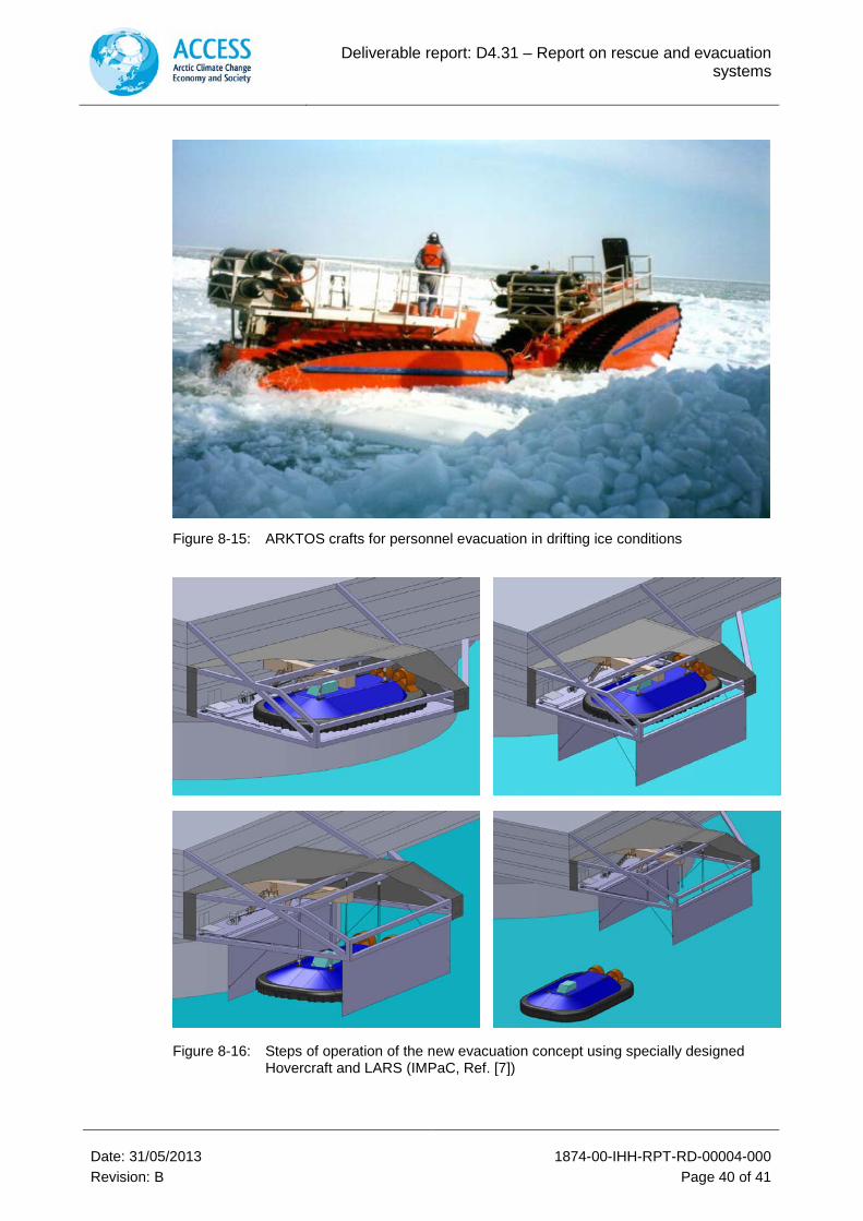
6.2.11 Design considerations for a new Launch and Recovery System (LARS)
Following considerations have been made during the design process of the LARS:
• Two hovercrafts are necessary to accommodate the required number of personnel (i.e. 1.5 times personnel on board)
• It was decided to attach the LARS on the side of the structure. This is due to the large footprint of about 600 m2 of the hovercraft and the height of about 8m. Deck space on offshore platforms is generally precious and needed for processing equipment
• The LARS shall be totally enclosed to protect the hovercraft and the launching equipment from the harsh environment, also to enable heating
• A door shall be incorporated through which the hovercraft can be launched
• It was decided that a winch and rope system for launching is the most appropriate system for the launching process since the launching appliance shall be functional without depending on the structure’s power
Deliverable report: D4.31 – Report on rescue and evacuation systems
Date: 31/05/2013 1874-00-IHH-RPT-RD-00004-000 Revision: B Page 22 of 41
• In winter ice rubble will form around the offshore structure, with large sail heights. The hovercraft cannot be launched on ice rubble and must therefore be placed as far away as possible from the structure. The built-up of the rubble field is highly dependent on the shape of the structure and has to be investigated for each case. For this design concept the topside of the structure is already overhanging. However, an additional 5m was incorporated
• An airtight walkway shall lead to the hovercraft, which can protect the evacuees from toxic gases
• As mentioned before, two hovercrafts shall be used. They shall be positioned on opposite edges of the offshore platform in order to increase the accessibility in case of fire, explosion e.g. or the ambient ice situation
Refer the CAD model for illustration of the system during launch (or recovery): Figure 8-16.
More detailed information about the case studies and the LARS design is given in the Master thesis, Rev. [7], which has been prepared in turn of the ACCESS project.
6.3 ESCAPE, EVACUATION AND RESCUE FROM MOBILE VESSELS / SHIPS
6.3.1 General
For EER from ships there is a potential to use existing rescue resources in Arctic waters as described in previous sections of this report (e.g. conventional lifeboats, liferafts, helicopters, ARKTOS™ vehicles, hydrocopter, air cushion vehicles, and Archimedian screw vehicles).
However some of these solutions are specifically designed for offshore installations and not necessarily applicable for mobile vessels and ships. In particular when large cruise ships are operating in ice-covered areas escape, evacuation and rescue is challenging due to the large number of persons on board to be evacuated.
The physical environment and weather conditions play an important role with respect to planning and execution of emergency response in cold and remote areas.
Sea ice, waves, currents and tides, wind, snow, rain and fog, cold temperatures, light levels and icing conditions have potential impacts on EER operations [Simões Ré & Veitch, 2008, Ref. [21]].
In the following some important specific EER means for use with ships have been assessed.
6.3.2 Assessment of different EER-Systems
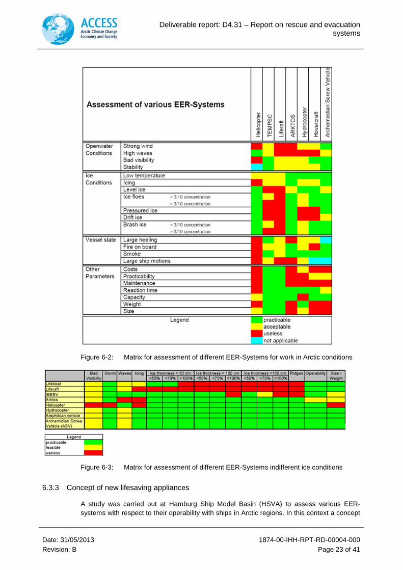
Figure 6-2 and Figure 6-3 illustrate the applicability of different maritime rescue and evacuation systems under Arctic conditions. The columns represent the different life saving appliances (e.g. helicopter, lifeboat, liferaft, etc.) while the lines represent possible environmental conditions and other parameters that are important in assessing the operability. According to the color code, “green” means that the respective concept for this condition is feasible. “Yellow” indicates that it is of limited use for the particular case. “Red” color means that the lifesaving appliance is useless while the “blue” color stands for “not applicable”.
Deliverable report: D4.31 – Report on rescue and evacuation systems
Date: 31/05/2013 1874-00-IHH-RPT-RD-00004-000 Revision: B Page 23 of 41
Figure 6-2: Matrix for assessment of different EER-Systems for work in Arctic conditions
Figure 6-3: Matrix for assessment of different EER-Systems indifferent ice conditions
6.3.3 Concept of new lifesaving appliances
A study was carried out at Hamburg Ship Model Basin (HSVA) to assess various EER-systems with respect to their operability with ships in Arctic regions. In this context a concept
Deliverable report: D4.31 – Report on rescue and evacuation systems
Date: 31/05/2013 1874-00-IHH-RPT-RD-00004-000 Revision: B Page 24 of 41
for a maritime rescue module was developed, which is described briefly below. For detailed information please refer to the bachelor thesis [Köster, 2012, Rev. [9]].
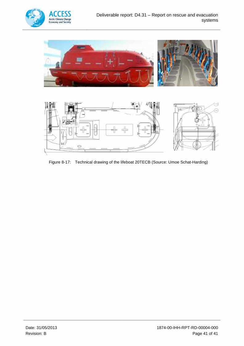
6.3.3.1 Conventional lifeboat
In the first step a conventional lifeboat (type Umoe Schat-Harding 20TECB) was investigated with respect to its strength behaviour for its use in ice-covered waters.
The stability calculation was omitted because this lifeboat type is built according to SOLAS regulations and fulfils the stability requirements. Figure 8-17 represents the technical drawings of the lifeboat.
Main parameters
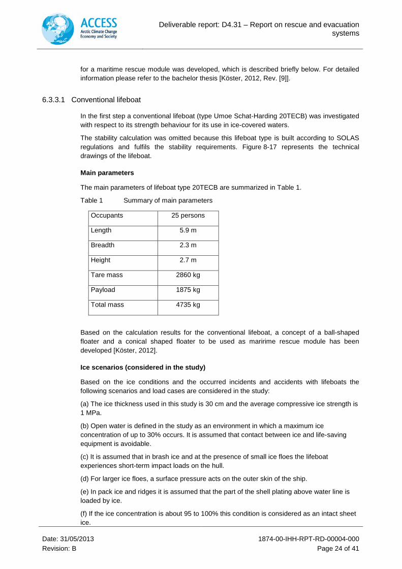
The main parameters of lifeboat type 20TECB are summarized in Table 1.
Table 1 Summary of main parameters
Occupants 25 persons
Length 5.9 m
Breadth 2.3 m
Height 2.7 m
Tare mass 2860 kg
Payload 1875 kg
Total mass 4735 kg
Based on the calculation results for the conventional lifeboat, a concept of a ball-shaped floater and a conical shaped floater to be used as maririme rescue module has been developed [Köster, 2012].
Ice scenarios (considered in the study)
Based on the ice conditions and the occurred incidents and accidents with lifeboats the following scenarios and load cases are considered in the study:
(a) The ice thickness used in this study is 30 cm and the average compressive ice strength is 1 MPa.
(b) Open water is defined in the study as an environment in which a maximum ice concentration of up to 30% occurs. It is assumed that contact between ice and life-saving equipment is avoidable.
(c) It is assumed that in brash ice and at the presence of small ice floes the lifeboat experiences short-term impact loads on the hull.
(d) For larger ice floes, a surface pressure acts on the outer skin of the ship.
(e) In pack ice and ridges it is assumed that the part of the shell plating above water line is loaded by ice.
(f) If the ice concentration is about 95 to 100% this condition is considered as an intact sheet ice.
Deliverable report: D4.31 – Report on rescue and evacuation systems
Date: 31/05/2013 1874-00-IHH-RPT-RD-00004-000 Revision: B Page 25 of 41
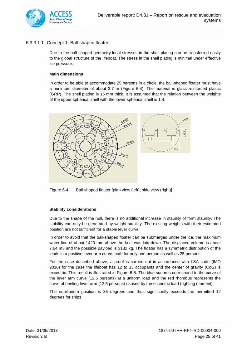
6.3.3.1.1 Concept 1: Ball-shaped floater
Due to the ball-shaped geometry local stresses in the shell plating can be transferred easily to the global structure of the lifeboat. The stress in the shell plating is minimal under effective ice pressure.
Main dimensions
In order to be able to accommodate 25 persons in a circle, the ball-shaped floater must have a minimum diameter of about 3.7 m (Figure 6-4). The material is glass reinforced plastic (GRP). The shell plating is 15 mm thick. It is assumed that the relation between the weights of the upper spherical shell with the lower spherical shell is 1:4.
Figure 6-4: Ball-shaped floater [plan view (left); side view (right)]
Stability considerations
Due to the shape of the hull, there is no additional increase in stability of form stability. The stability can only be generated by weight stability. The existing weights with their estimated position are not sufficient for a stable lever curve.
In order to avoid that the ball-shaped floater can be submerged under the ice, the maximum water line of about 1420 mm above the keel was laid down. The displaced volume is about 7.64 m3 and the possible payload is 3132 kg. The floater has a symmetric distribution of the loads in a positive lever arm curve, both for only one person as well as 25 persons.
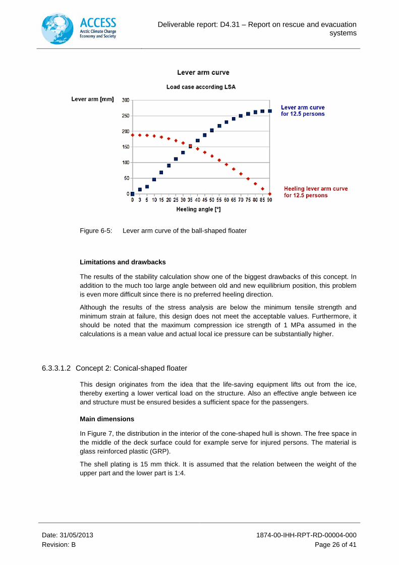
For the case described above, a proof is carried out in accordance with LSA code (IMO 2010) for the case the lifeboat has 12 to 13 occupants and the center of gravity (CoG) is excentric. This result is illustrated in Figure 6-5. The blue squares correspond to the curve of the lever arm curve (12.5 persons) at a uniform load and the red rhombus represents the curve of heeling lever arm (12.5 persons) caused by the eccentric load (righting moment).
The equilibrium position is 35 degrees and thus significantly exceeds the permitted 12 degrees for ships.
Deliverable report: D4.31 – Report on rescue and evacuation systems
Date: 31/05/2013 1874-00-IHH-RPT-RD-00004-000 Revision: B Page 26 of 41
Figure 6-5: Lever arm curve of the ball-shaped floater
Limitations and drawbacks
The results of the stability calculation show one of the biggest drawbacks of this concept. In addition to the much too large angle between old and new equilibrium position, this problem is even more difficult since there is no preferred heeling direction.
Although the results of the stress analysis are below the minimum tensile strength and minimum strain at failure, this design does not meet the acceptable values. Furthermore, it should be noted that the maximum compression ice strength of 1 MPa assumed in the calculations is a mean value and actual local ice pressure can be substantially higher.
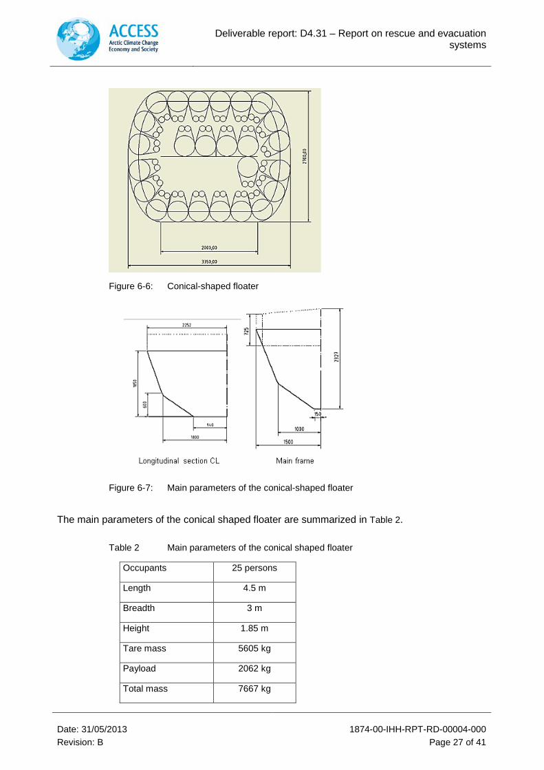
6.3.3.1.2 Concept 2: Conical-shaped floater
This design originates from the idea that the life-saving equipment lifts out from the ice, thereby exerting a lower vertical load on the structure. Also an effective angle between ice and structure must be ensured besides a sufficient space for the passengers.
Main dimensions
In Figure 7, the distribution in the interior of the cone-shaped hull is shown. The free space in the middle of the deck surface could for example serve for injured persons. The material is glass reinforced plastic (GRP).
The shell plating is 15 mm thick. It is assumed that the relation between the weight of the upper part and the lower part is 1:4.
Deliverable report: D4.31 – Report on rescue and evacuation systems
Date: 31/05/2013 1874-00-IHH-RPT-RD-00004-000 Revision: B Page 27 of 41
Figure 6-6: Conical-shaped floater
Figure 6-7: Main parameters of the conical-shaped floater
The main parameters of the conical shaped floater are summarized in Table 2.
Table 2 Main parameters of the conical shaped floater
Occupants 25 persons
Length 4.5 m
Breadth 3 m
Height 1.85 m
Tare mass 5605 kg
Payload 2062 kg
Total mass 7667 kg
Deliverable report: D4.31 – Report on rescue and evacuation systems
Date: 31/05/2013 1874-00-IHH-RPT-RD-00004-000 Revision: B Page 28 of 41
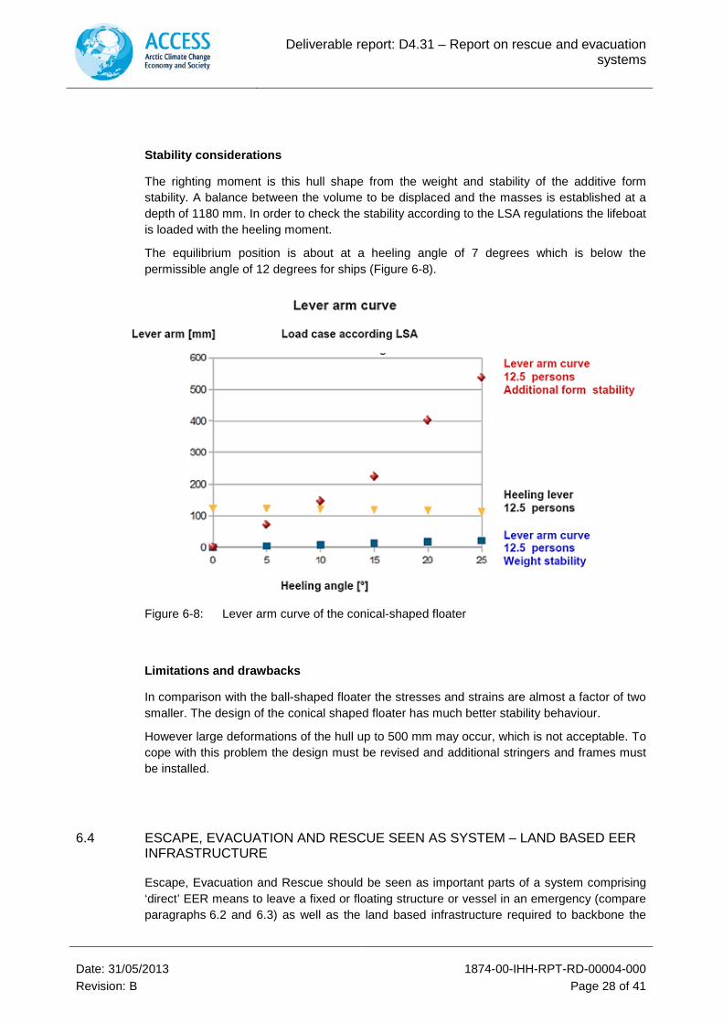
Stability considerations
The righting moment is this hull shape from the weight and stability of the additive form stability. A balance between the volume to be displaced and the masses is established at a depth of 1180 mm. In order to check the stability according to the LSA regulations the lifeboat is loaded with the heeling moment.
The equilibrium position is about at a heeling angle of 7 degrees which is below the permissible angle of 12 degrees for ships (Figure 6-8).
Figure 6-8: Lever arm curve of the conical-shaped floater
Limitations and drawbacks
In comparison with the ball-shaped floater the stresses and strains are almost a factor of two smaller. The design of the conical shaped floater has much better stability behaviour.
However large deformations of the hull up to 500 mm may occur, which is not acceptable. To cope with this problem the design must be revised and additional stringers and frames must be installed.
6.4 ESCAPE, EVACUATION AND RESCUE SEEN AS SYSTEM – LAND BASED EER INFRASTRUCTURE
Escape, Evacuation and Rescue should be seen as important parts of a system comprising ‘direct’ EER means to leave a fixed or floating structure or vessel in an emergency (compare paragraphs 6.2 and 6.3) as well as the land based infrastructure required to backbone the
Deliverable report: D4.31 – Report on rescue and evacuation systems
Date: 31/05/2013 1874-00-IHH-RPT-RD-00004-000 Revision: B Page 29 of 41
EER means. A dedicated approach to this backbone suitable to work in the Arctic has been developed by IMPaC (Ref. [8]).
Aim is to provide a modular concept for settlements (knots) which can be adapted to meet the requirements of a changing number of personnel working in remote areas in the Arctic. The modules comprise airport facilities, harbour facilities (for provision and for the EER vessels) and of course accommodation. The locations of these knots have been determined for the Northern Sea Route which has been exemplary analysed. The flight radii of suitable aircrafts and/or helicopters have been taken in order to get a seamless infrastructure for the required transports to and from the remote locations along the Arctic (here: Russian) coastline.
The analyses illustrates impressively the need for such a backbone in turn of an increasing approach to the Arctic e.g. by means of large Cruise Ships carrying several hundreds of people.
Deliverable report: D4.31 – Report on rescue and evacuation systems
Date: 31/05/2013 1874-00-IHH-RPT-RD-00004-000 Revision: B Page 30 of 41
7 CONCLUSION
The Report summarises results from assessments made for current technology and strategy to cope with Escape, Evacuation and Rescue (EER) from Arctic facilities of the Oil and Gas industry as well as from all kinds of vessels traveling or passing the Arctic for different purposes (fishery, tourism, cargo transport).
A huge number of different existing EER means have been identified, most of them have been already considered by other assessments initiated by the Oil and Gas industry, by classification societies or governmental offices of the Arctic surrounding countries.
It turns out that the dominant number of EER means is suitable to work in a lot of today’s realistic scenarios. More problematic seems to be their application in near future scenarios where e.g. a relatively huge number of persons (more than 100, up to 1000 or more!) have to be handled by the applied EER scheme from very remotely located facilities or touristic vessels far away from the next onshore infrastructure. For these scenarios no suitable concepts have been identified or developed up to now.
Thus, it can be seen that there are still deficiencies in the “in-ice” evacuation technologies now available, for particular situations that can be encountered in ice-covered waters. Methods that will actually work with a reasonable degree of efficiency and reliability depend on the particulars of the ice environment and the nature of the on board problem causing the evacuation. There are still a number of “generic gaps” that should be pursued.
Added in Revision B:
The following main gaps have been identified in the existing EER technology in terms of its applicability in the Arctic:
• The today available EER means are suitable to work with small to medium numbers of persons to be evacuated from vessels and platforms in open water conditions in areas with standard land based infrastructure. This fact significantly changes when the same EER means shall be used in Arctic conditions which is often characterised by icing at structures, drifting ice and icebergs, high waves and very poor visibility. In addition, experience teaches that problems tend to occur far away from any infrastructure
• Especially the huge number of persons (up to 4.500 incl. crew and tourists) carried by some large Cruise ships already visiting the Arctic poses a major challenge to current and future planned EER infrastructure: the on board EER means (lifeboats etc.) and the land based ‘backbone’ of these EER means (the land rescue stations with harbour facilities and airport etc.)
• EER means have to consider specific problems like the ice built-up directly at the platforms and ships, which can result in an inability to deploy the small boats or rafts etc. in a safe way as they would have to break the ice right during deployment (compare Figure 8-2, Figure 8-3, Figure 8-5). So, e.g. free falling boats are most likely not suitable and have to be replaced or added by more controlled techniques for launch and recovery ‘behind the ice barrier’
Deliverable report: D4.31 – Report on rescue and evacuation systems
Date: 31/05/2013 1874-00-IHH-RPT-RD-00004-000 Revision: B Page 31 of 41
8 REFERENCES
[1] Norwegian Petroleum Directorate: factpages.npd.no/factpages/default.aspx
[2] Shtokman, Information from project official Website: www.shtokman.ru/en/
[3] Hibernia Gravity Base Structure (GBS), www.hibernia.ca
[4] Shell Prelude FLNG project, Information from project official Website: www.shell.com/home/content/aboutshell/our_strategy/major_projects_2/prelude_flng/
[5] Facts about the Goliat FPSO project from major stakeholder ENI Norge: www.eninorge.no/EniNo.nsf/page/DED71D42177627E0C12574E60040DAF9?OpenDocument&Lang=english
[6] Arnold Marsden and Melanie Totten, Shell International Exploration and Production Inc., and Walt Spring, Bear Ice Technology: Feasibility of Escape, Evacuation and Rescue for Facilities in Arctic Shear Zone Environment, OTC Arctic Technology Conference, 7-9 February 2011, Houston, Texas, USA
[7] IMPaC (Ria Brünig): Evaluation of suitable Rescue and Evacuation Systems for Offshore Structures in the Arctic Ocean, Master Thesis in Cooperation with University of Strathclyde (UK), 2012
[8] IMPaC: Escape, Evacuation and Rescue from Arctic Facilities – A Systematic Approach, project ACCESS, 1874-00-IHH-RPT-RD-00007-000
[9] Köster, J, 2012. Maritimes Rettungsmodul für die Arktis. Bachelor Thesis, Technical University Hamburg-Harburg, Institute for Ship Structural Design and Analysis
[10] Facts about the IBEEV vessels for the Caspian, http://remontowa-mdc.pl/title,Ice_Breaking_Emergency_Evacuation_Vessel,pid,73
[11] Facts about the Boat-in-a-Box System: http://nadiro.com/products/arctic
[12] Facts about the ARKTOS Evacuation Craft: http://www.arktoscraft.com/index.htm
[13] Facts about the Hovercraft applied in Arctic conditions: http://www.polarhovercraft.no/
[14] Facts about TEMPSC: http://www.survivalcraft.com/services/lifeboats-davits/tempsc/
[15] International Maritime Organization (IMO), Guidelines, www.imo.org
[16] Johansson, B. 2006. Ice breaking life boat. Proceedings, ICETECH, 06-162-RF, Society of Naval Architects and Marine Engineers, Banff, 7 p.
[17] Life-Saving Appliances - Including LAS Code. London : International Maritime Organization, 2010. ISBN 978 92 801 1507 9
[18] Simões Ré, A. and Veitch, B., 2007. Lifeboat Operational performance in Cold Environment, The Royal Institution of Naval Architects Design & Construction of Vessels Operating in Low Temperature Environments
[19] Simões Ré, A. and Veitch, B. 2007a. Lifeboat operational performance in cold environments. Proceedings, Design and Construction of Vessels Operating in Low Temperature Environments, Royal Institution of Naval Architects, London, 6 p.
[20] Simões Ré, A. and Veitch, B. 2007b. A comparison of three types of evacuation system. Transactions, Society of Naval Architects and Marine Engineers, 20 p.
Deliverable report: D4.31 – Report on rescue and evacuation systems
Date: 31/05/2013 1874-00-IHH-RPT-RD-00004-000 Revision: B Page 32 of 41
[21] Simões Ré, A. & Veitch, B., 2008. Escape-Evacuation-Rescue response in ice-covered regions, Proceedings of the 18th International Offshore and Polar Engineering Conference Vancouver, BC, Canada, July 6-11, 2008. ISBN 978-1-880653-70-8 (Set); ISBN 1-880653-68-0 (Set)
[22] Simões Ré,A. Kuczora, A. & Veitch, B., 2008. Field trials of an instrumented lifeboat in ice conditions, Proceedings of the 18th International Offshore and Polar Engineering Conference Vancouver, BC, Canada, July 6-11, 2008. ISBN 978-1-880653-70-8 (Set); ISBN 1-880653-68-0 (Set)
[23] Timco, G.W. and Dickins, D.F. 2005. Environmental guidelines for EER systems in ice-covered waters. Cold Regions Science and Technology, 42(3): 67-85.
[24] Veitch, B., Bose, N., Jordaan, I., Spencer, D. and Haddara, M. 2004. Ice capable ships. In Ship Design and Construction (T. Lamb, ed.), Society of Naval Architects and Marine Engineers, 36 p.
[25] Wright, B.D., Timco, G.W. , Dunderdale, P. and Smith, M. ,2002. Evaluation of Emergency Evacuation Systems in Ice-Covered Waters, PERD/CHC Report 11-39, 100p. Wright & Associates, Calgary, Canada.
Deliverable report: D4.31 – Report on rescue and evacuation systems
Date: 31/05/2013 1874-00-IHH-RPT-RD-00004-000 Revision: B Page 33 of 41
ANNEX
Images, Illustrations Annex A
Deliverable report: D4.31 – Report on rescue and evacuation systems
Date: 31/05/2013 1874-00-IHH-RPT-RD-00004-000 Revision: B Page 34 of 41
Images, Illustrations Annex A
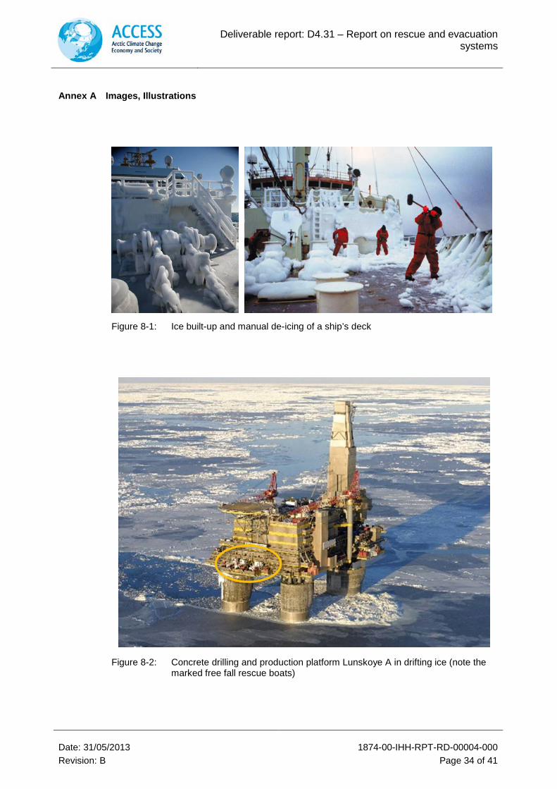
Figure 8-1: Ice built-up and manual de-icing of a ship’s deck
Figure 8-2: Concrete drilling and production platform Lunskoye A in drifting ice (note the marked free fall rescue boats)
Deliverable report: D4.31 – Report on rescue and evacuation systems
Date: 31/05/2013 1874-00-IHH-RPT-RD-00004-000 Revision: B Page 35 of 41
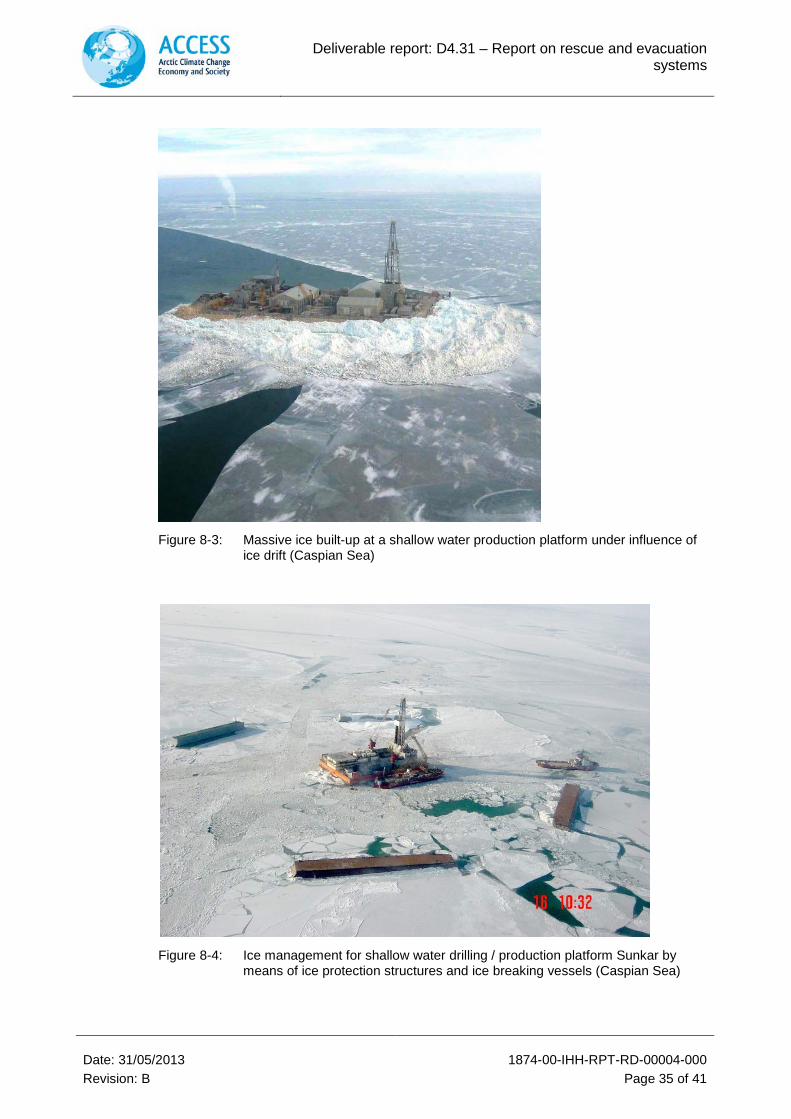
Figure 8-3: Massive ice built-up at a shallow water production platform under influence of ice drift (Caspian Sea)
Figure 8-4: Ice management for shallow water drilling / production platform Sunkar by means of ice protection structures and ice breaking vessels (Caspian Sea)
Deliverable report: D4.31 – Report on rescue and evacuation systems
Date: 31/05/2013 1874-00-IHH-RPT-RD-00004-000 Revision: B Page 36 of 41
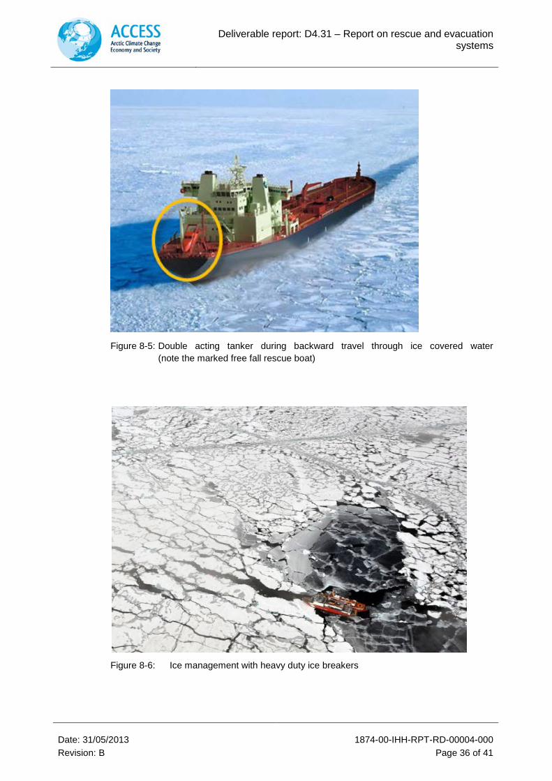
Figure 8-5: Double acting tanker during backward travel through ice covered water (note the marked free fall rescue boat)
Figure 8-6: Ice management with heavy duty ice breakers
Deliverable report: D4.31 – Report on rescue and evacuation systems
Date: 31/05/2013 1874-00-IHH-RPT-RD-00004-000 Revision: B Page 37 of 41
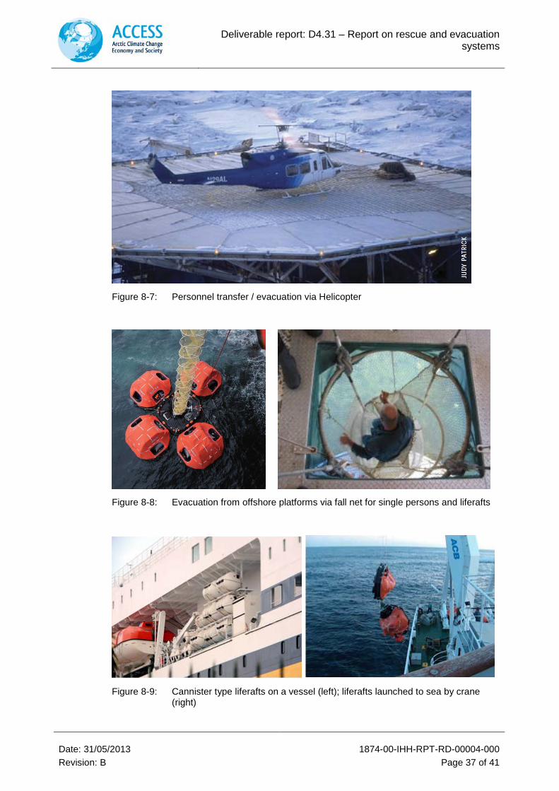
Figure 8-7: Personnel transfer / evacuation via Helicopter
Figure 8-8: Evacuation from offshore platforms via fall net for single persons and liferafts
Figure 8-9: Cannister type liferafts on a vessel (left); liferafts launched to sea by crane (right)
Deliverable report: D4.31 – Report on rescue and evacuation systems
Date: 31/05/2013 1874-00-IHH-RPT-RD-00004-000 Revision: B Page 38 of 41
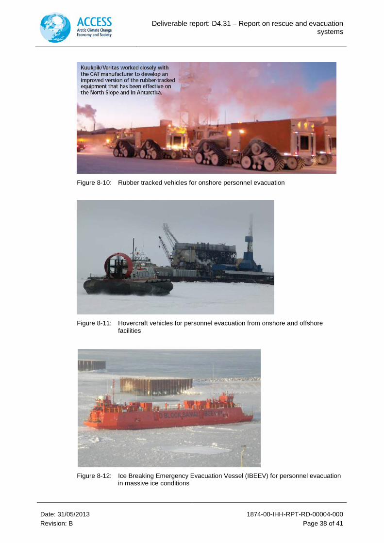
Figure 8-10: Rubber tracked vehicles for onshore personnel evacuation
Figure 8-11: Hovercraft vehicles for personnel evacuation from onshore and offshore facilities
Figure 8-12: Ice Breaking Emergency Evacuation Vessel (IBEEV) for personnel evacuation in massive ice conditions
Deliverable report: D4.31 – Report on rescue and evacuation systems
Date: 31/05/2013 1874-00-IHH-RPT-RD-00004-000 Revision: B Page 39 of 41
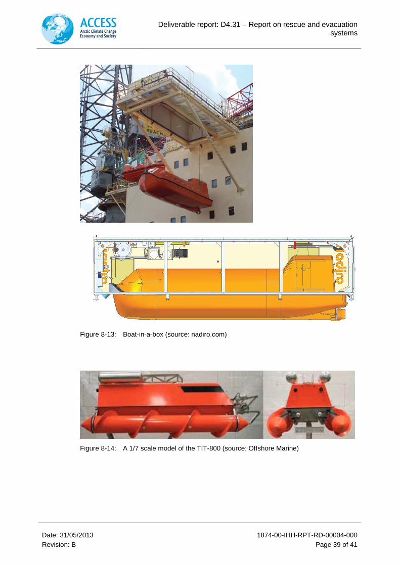
Figure 8-13: Boat-in-a-box (source: nadiro.com)
Figure 8-14: A 1/7 scale model of the TIT-800 (source: Offshore Marine)
Deliverable report: D4.31 – Report on rescue and evacuation systems
Date: 31/05/2013 1874-00-IHH-RPT-RD-00004-000 Revision: B Page 40 of 41
Figure 8-15: ARKTOS crafts for personnel evacuation in drifting ice conditions
Figure 8-16: Steps of operation of the new evacuation concept using specially designed Hovercraft and LARS (IMPaC, Ref. [7])
Deliverable report: D4.31 – Report on rescue and evacuation systems
Date: 31/05/2013 1874-00-IHH-RPT-RD-00004-000 Revision: B Page 41 of 41
Figure 8-17: Technical drawing of the lifeboat 20TECB (Source: Umoe Schat-Harding)