Embed Size (px)
Citation preview
10/98 P/N 35115D © 1998 Radionics, Inc.
D2412U, D2412UE Control / CommunicatorInstallation Manual
D2412U, D2412UE Installation GuidePage 210/98 P/N 35115D © 1998 Radionics, Inc.
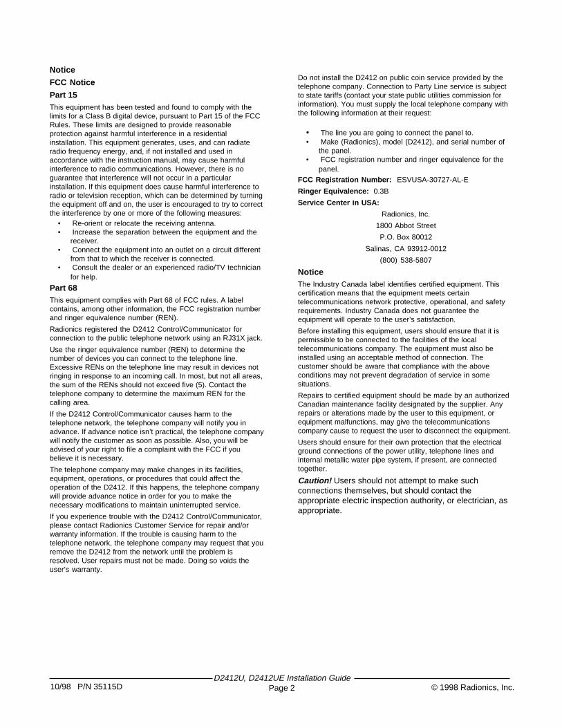
Notice
FCC Notice
Part 15This equipment has been tested and found to comply with thelimits for a Class B digital device, pursuant to Part 15 of the FCCRules. These limits are designed to provide reasonableprotection against harmful interference in a residentialinstallation. This equipment generates, uses, and can radiateradio frequency energy, and, if not installed and used inaccordance with the instruction manual, may cause harmfulinterference to radio communications. However, there is noguarantee that interference will not occur in a particularinstallation. If this equipment does cause harmful interference toradio or television reception, which can be determined by turningthe equipment off and on, the user is encouraged to try to correctthe interference by one or more of the following measures:
• Re-orient or relocate the receiving antenna.• Increase the separation between the equipment and the
receiver.• Connect the equipment into an outlet on a circuit different
from that to which the receiver is connected.• Consult the dealer or an experienced radio/TV technician
for help.
Part 68This equipment complies with Part 68 of FCC rules. A labelcontains, among other information, the FCC registration numberand ringer equivalence number (REN).
Radionics registered the D2412 Control/Communicator forconnection to the public telephone network using an RJ31X jack.
Use the ringer equivalence number (REN) to determine thenumber of devices you can connect to the telephone line.Excessive RENs on the telephone line may result in devices notringing in response to an incoming call. In most, but not all areas,the sum of the RENs should not exceed five (5). Contact thetelephone company to determine the maximum REN for thecalling area.
If the D2412 Control/Communicator causes harm to thetelephone network, the telephone company will notify you inadvance. If advance notice isn’t practical, the telephone companywill notify the customer as soon as possible. Also, you will beadvised of your right to file a complaint with the FCC if youbelieve it is necessary.
The telephone company may make changes in its facilities,equipment, operations, or procedures that could affect theoperation of the D2412. If this happens, the telephone companywill provide advance notice in order for you to make thenecessary modifications to maintain uninterrupted service.
If you experience trouble with the D2412 Control/Communicator,please contact Radionics Customer Service for repair and/orwarranty information. If the trouble is causing harm to thetelephone network, the telephone company may request that youremove the D2412 from the network until the problem isresolved. User repairs must not be made. Doing so voids theuser’s warranty.
Do not install the D2412 on public coin service provided by thetelephone company. Connection to Party Line service is subjectto state tariffs (contact your state public utilities commission forinformation). You must supply the local telephone company withthe following information at their request:
• The line you are going to connect the panel to.• Make (Radionics), model (D2412), and serial number of
the panel.• FCC registration number and ringer equivalence for the
panel.FCC Registration Number: ESVUSA-30727-AL-E
Ringer Equivalence: 0.3B
Service Center in USA:
Radionics, Inc.
1800 Abbot Street
P.O. Box 80012
Salinas, CA 93912-0012
(800) 538-5807
NoticeThe Industry Canada label identifies certified equipment. Thiscertification means that the equipment meets certaintelecommunications network protective, operational, and safetyrequirements. Industry Canada does not guarantee theequipment will operate to the user’s satisfaction.
Before installing this equipment, users should ensure that it ispermissible to be connected to the facilities of the localtelecommunications company. The equipment must also beinstalled using an acceptable method of connection. Thecustomer should be aware that compliance with the aboveconditions may not prevent degradation of service in somesituations.
Repairs to certified equipment should be made by an authorizedCanadian maintenance facility designated by the supplier. Anyrepairs or alterations made by the user to this equipment, orequipment malfunctions, may give the telecommunicationscompany cause to request the user to disconnect the equipment.
Users should ensure for their own protection that the electricalground connections of the power utility, telephone lines andinternal metallic water pipe system, if present, are connectedtogether.
Caution! Users should not attempt to make suchconnections themselves, but should contact theappropriate electric inspection authority, or electrician, asappropriate.
10/98 P/N 35115D© 1998 Radionics, Inc.D2412U, D2412UE Installation Guide
Page 3
Table of Contents
1.0 Introduction ....................................................... 41.1 D2412 Control / Communicator ....................... 4
Panel Assembly .................................................. 4Hardware Pack ................................................... 4Literature Pack (L2412-LIT) ............................... 4
1.2 Ordered Separately ......................................... 4D202A Keypad ................................................... 4D205 Keypad ...................................................... 4D206 Keypad ...................................................... 4D220A Keypad ................................................... 4D222 Keypad ...................................................... 4D223 Keypad ...................................................... 4Battery ................................................................ 4D132A or D192C ................................................ 4
1.3 Enclosure Options ........................................... 41.4 Listings and Approvals ..................................... 5
Fire ..................................................................... 5Burglary .............................................................. 5
2.0 Getting Started .................................................. 52.1 Mount the Enclosure ........................................ 5
Mounting the D2412U in the D2203 Enclosure .. 5Mounting the D2412UE in the D2803 Enclosure 5
2.2 Run the Premises Wiring ................................. 5Wire Length ........................................................ 5EMI (Electro Magnetic Interference) .................. 6
2.3 Connect to Earth Ground ................................. 62.4 Transformer (16.5VAC) ................................... 62.5 Battery .............................................................. 6
3.0 Charge the Battery as You Work ..................... 63.1 Lock the Standby Switch .................................. 6
4.0 Install Detection Devices,Keypads and Bells . 64.1 No Connection to the Panel Yet ....................... 64.2 Number of Sensors .......................................... 6
5.0 Continue Connections to the Panel ................ 75.1 Power Down First ............................................ 75.2 Alarm Output (+Alrm-) ..................................... 7
Available Power .................................................. 7Fire System Power Formula .............................. 7
5.4 Auxiliary Power (+Aux) .................................... 75.5 Checking Continuous Current Draw ................ 75.6 External Relays (Ext1 and Ext2) ...................... 7
6.0 Connect the Points ........................................... 86.1 On-Board Points .............................................. 8
Point 1 (1+ and 1-) .............................................. 8Points 2 to 6 ........................................................ 8Point Expanders for the D2412U, Wired or RF .. 9
7.0 Make the Telephone Connections ................... 97.1 Phone Jack ...................................................... 97.2 Phone Cord .................................................... 10
7.3 Power Up ....................................................... 107.4 Program the Panel ......................................... 107.5 Unlock the Standby Switch ............................ 10
RAM II ResetBye does not disarm the panel ... 107.6 Check for Alarm Verification .......................... 107.7 Test the System ............................................. 10
Clear After Test ................................................. 108.0 Detailed Description ....................................... 10
8.1 Primary (AC) Power Circuit ........................... 10AC Power Failure ............................................. 11
8.2 Secondary (DC) Power .................................. 11Lead Acid Batteries Only .................................. 11Battery Replacement ....................................... 11Battery Supervision .......................................... 11Investigate Low Battery Reports Immediately .. 11Battery Charging Circuit Float Charge ............. 11Battery Discharge/Recharge Schedule(No AC Power) ................................................. 11
8.3 Power Outputs ............................................... 11D2412 Circuit Protection .................................. 11
8.4 Telephone ...................................................... 12Dialing Format .................................................. 12Communication Failure .................................... 12Ground Start ..................................................... 12
8.5 Points ............................................................. 12Point Parameters .............................................. 12Point Response Time ....................................... 12
8.6 Keyswitch ....................................................... 12Description ....................................................... 12Programming ................................................... 12Installation ........................................................ 12Keyswitch Operation ........................................ 12Silencing the Bell .............................................. 12Easikey ............................................................. 13
9.0 Installation Guide for UL Applications ........ 149.1 Introduction .................................................... 149.2 Optional Compatible Equipment .................... 14
Burglary Applications ....................................... 14Fire Applications .............................................. 14Sounding Device .............................................. 14Enclosures ....................................................... 14
9.3 Standby Battery Requirements ...................... 16Household Burglary and Commercial Burglary 16Standby Battery Calculation for Fire AlarmApplications ...................................................... 16
10.0 System Wiring Diagram, Issue A ................. 1711.0 Specifications ................................................ 1812.0 Terminal Quick Reference ............................ 19
D2412U, D2412UE Installation GuidePage 410/98 P/N 35115D © 1998 Radionics, Inc.
1.0 Introduction
1.1 D2412 Control / CommunicatorThe Radionics D2412 Control/Communicator is shippedpre-assembled from the factory. You should receive thefollowing parts with your D2412 panel.
Panel Assembly• D2412U or D2412UE Panel• D2203 Enclosure for D2412U• D2803 for D2412UE• D1640 Transformer for D2412U• D1625 for D2412UE• Technogram: Smoke Detectors Compatible with the
D2412 (P/N: 35112)• Release Notes: Firmware Revision (P/N: 35111)
Hardware Pack• One 2k ohm end-of-line resistor for Point 1
(P/N: 15-03130-010)• Five 1k ohm end-of-line resistors for Points 2 - 6
(P/N: 30-01098-102)• Two #6 by 3/8” sheet metal screws to secure the
Enclosure cover.• Four plastic Clips: for mounting the panel to the
enclosure• Two thread forming screws: for mounting the panel to
the enclosureLiterature Pack (L2412-LIT)
• Installation Manual (P/N: 35115)• Program Entry Guide (P/N: 35114)• Program Record Sheet (P/N: 35113)• Keypad Diagnostics Sheet (P/N: 35110)
1.2 Ordered SeparatelyD202A Keypad
Each D202A includes the following:• D202A Keypad• Installation Sheet (P/N: 74-07118-000)• User’s Cards (P/N: 71-07090-000)• Security System User’s Guide (P/N: 71-07117-000)• Getting Started with Your Security System
(P/N: 71-07372-000)• Three-wire data cable assembly (15-07032-000)
D205 Keypad
Each D205 includes the following:• D205 Keypad• Installation Sheet (P/N: 31945)• Security System User’s Guide (P/N: 71-07117-000)• Getting Started with Your Security System
(P/N: 71-07372-000)• Three-wire data cable assembly (P/N: 15-07032-000)
D206 Keypad
Each D206 includes the following:• D206 Keypad• Installation Sheet (P/N: 31946)• Security System User’s Guide (P/N: 71-07117-000)• Getting Started with Your Security System
(P/N: 71-07372-000)• Three-wire data cable assembly (P/N: 15-07032-000)
D220A Keypad
Each D220A includes the following:• D220A Keypad• Installation Sheet (P/N: 74-07363-000)• User’s Reference Card (P/N: 71-05432-011)• Security System User’s Guide (P/N: 71-07374-000)• Getting Started with Your Security System
(P/N: 71-07372-000)• Three-wire data cable assembly (P/N: 15-07032-000)
D222 Keypad
Each D222 includes the following:• D222 English Keypad and Point Expander• Installation Sheet (P/N: 74-07362-000)• User’s Reference Card (P/N: 71-04523-010)• Security System User’s Guide (P/N: 71-07374-000)• Getting Started with Your Security System
(P/N: 71-07372-000)• Three-wire data cable assembly (P/N: 15-07032-000)• Six-wire point cable assembly (P/N: 15-07251-000)• Four 1kW end-of-line resistors (P/N: 30-01098-102)
D223 Keypad
Each D223 includes the following:• D223 English Keypad• Installation Sheet (P/N: 74-07490-000)• User’s Reference Card (P/N: 71-04523-010)• Security System User’s Guide (P/N: 71-07373-000)• Getting Started with Your Security System
(P/N: 71-07372-000)• Three-wire data cable assembly (P/N: 15-07032-000)
Battery
Order a D126 Battery (12 V 7.0Ah) to complete a basicD2412 installation.
D132A or D192C
A D132A Smoke Detector Reversing Relay Module (andcompatible smoke detectors), or a D192C NACSupervision Module must be used for fire or combined fire/burglary installations.
1.3 Enclosure OptionsThe D2412U is shipped in the D2203 enclosure; theD2412UE is shipped in the D2803. If you want to mountthe D2412U or D2412UE in one of the optional enclosureslisted below, order the D2412UM or D2412UEM, and theenclosure of your choice.
• D8103 Universal Enclosure• D8108A Attack Resistant Enclosure• D8109 Fire Rated Enclosure
10/98 P/N 35115D© 1998 Radionics, Inc.D2412U, D2412UE Installation Guide
Page 5
1.4 Listings and ApprovalsThe D2412U and D2412UE have the following approvals:
Fire• Underwriters Laboratories as a Household Fire and
Burglary Warning System Control Unit for NFPA 72(Chapter 2) Household Fire Warning.
• CSFM (Residential)• UL 985 Household Fire Warning Systems
Burglary• UL 1023 Household Burglary Alarm• UL 365 Police Station Connect• UL 609 Local Burglary Alarm• UL 1076 Proprietary Burglary Alarm• UL 1610 Central Station
2.0 Getting StartedReview this manual before you begin to determinehardware and wiring requirements for the features youwant to use. Have the following handy as you read throughthe manual:
• Program Record Sheet (35113)• Program Entry Guide (35114)• Security System User’s Guide
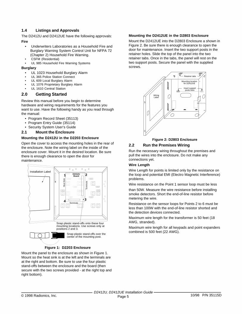
2.1 Mount the EnclosureMounting the D2412U in the D2203 Enclosure
Open the cover to access the mounting holes in the rear ofthe enclosure. Note the wiring label on the inside of theenclosure cover. Mount it in the desired location. Be surethere is enough clearance to open the door formaintenance.
2Installation Label
Snap plastic stand-offs onto these fourmounting locations. Use screws only atpositions 2 and 3.
1
34
D2412UBoard
Snap plastic stand-offs over thecenter of the mounting post.
Terminals
Figure 1: D2203 Enclosure
Mount the panel to the enclosure as shown in Figure 1.Mount so the heat sink is at the left and the terminals areat the right and bottom. Be sure to use the four plasticstand-offs between the enclosure and the board (thensecure with the two screws provided - at the right top andright bottom).
Mounting the D2412UE in the D2803 Enclosure
Mount the D2412UE into the D2803 Enclosure a shown inFigure 2. Be sure there is enough clearance to open thedoor for maintenance. Insert the two support posts in theretainer holes. Slide the top of the panel into the tworetainer tabs. Once in the tabs, the panel will rest on thetwo support posts. Secure the panel with the suppliedscrews.
WiringLabel
Retainer tabs
Insert supportposts here
Mounting locationfor D2412UE
Figure 2: D2803 Enclosure
2.2 Run the Premises WiringRun the necessary wiring throughout the premises andpull the wires into the enclosure. Do not make anyconnections yet.
Wire Length
Wire Length for points is limited only by the resistance onthe loop and potential EMI (Electro Magnetic Interference)problems.
Wire resistance on the Point 1 sensor loop must be less
than 50W. Measure the wire resistance before installingsmoke detectors. Short the end-of-line resistor beforemetering the wire.
Resistance on the sensor loops for Points 2 to 6 must beless than 100W with the end-of-line resistor shorted andthe detection devices connected.
Maximum wire length for the transformer is 50 feet (18AWG, stranded).
Maximum wire length for all keypads and point expanderscombined is 500 feet (22 AWG).
D2412U, D2412UE Installation GuidePage 610/98 P/N 35115D © 1998 Radionics, Inc.
3.0 Charge the Battery as You Work
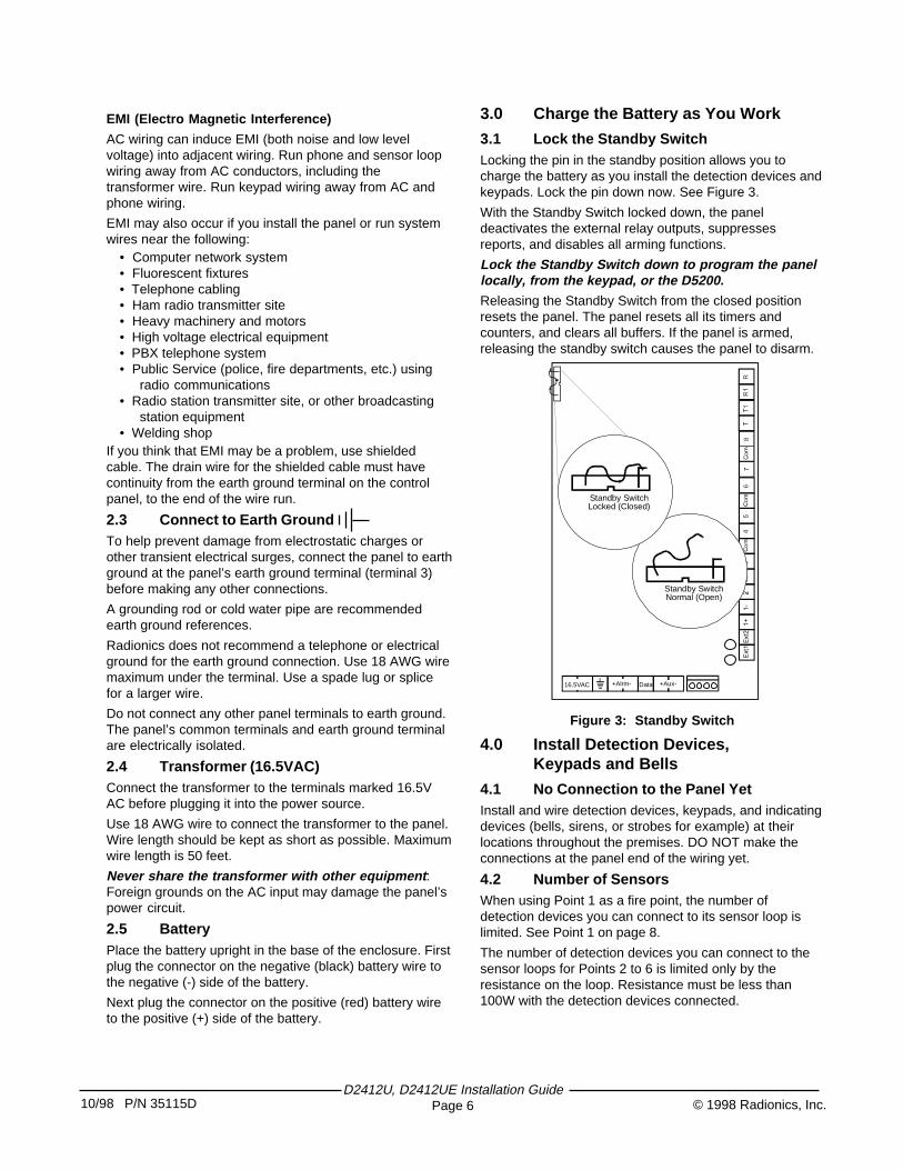
3.1 Lock the Standby SwitchLocking the pin in the standby position allows you tocharge the battery as you install the detection devices andkeypads. Lock the pin down now. See Figure 3.
With the Standby Switch locked down, the paneldeactivates the external relay outputs, suppressesreports, and disables all arming functions.
Lock the Standby Switch down to program the panellocally, from the keypad, or the D5200.Releasing the Standby Switch from the closed positionresets the panel. The panel resets all its timers andcounters, and clears all buffers. If the panel is armed,releasing the standby switch causes the panel to disarm.
16.5VAC +Alrm- Data +Aux-
Standby SwitchNormal (Open)
Standby SwitchLocked (Closed)
Figure 3: Standby Switch
4.0 Install Detection Devices,Keypads and Bells
4.1 No Connection to the Panel YetInstall and wire detection devices, keypads, and indicatingdevices (bells, sirens, or strobes for example) at theirlocations throughout the premises. DO NOT make theconnections at the panel end of the wiring yet.
4.2 Number of SensorsWhen using Point 1 as a fire point, the number ofdetection devices you can connect to its sensor loop islimited. See Point 1 on page 8.
The number of detection devices you can connect to thesensor loops for Points 2 to 6 is limited only by theresistance on the loop. Resistance must be less than100W with the detection devices connected.
EMI (Electro Magnetic Interference)
AC wiring can induce EMI (both noise and low levelvoltage) into adjacent wiring. Run phone and sensor loopwiring away from AC conductors, including thetransformer wire. Run keypad wiring away from AC andphone wiring.
EMI may also occur if you install the panel or run systemwires near the following:
• Computer network system• Fluorescent fixtures• Telephone cabling• Ham radio transmitter site• Heavy machinery and motors• High voltage electrical equipment• PBX telephone system• Public Service (police, fire departments, etc.) using
radio communications• Radio station transmitter site, or other broadcasting
station equipment• Welding shop
If you think that EMI may be a problem, use shieldedcable. The drain wire for the shielded cable must havecontinuity from the earth ground terminal on the controlpanel, to the end of the wire run.
2.3 Connect to Earth GroundTo help prevent damage from electrostatic charges orother transient electrical surges, connect the panel to earthground at the panel’s earth ground terminal (terminal 3)before making any other connections.
A grounding rod or cold water pipe are recommendedearth ground references.
Radionics does not recommend a telephone or electricalground for the earth ground connection. Use 18 AWG wiremaximum under the terminal. Use a spade lug or splicefor a larger wire.
Do not connect any other panel terminals to earth ground.The panel’s common terminals and earth ground terminalare electrically isolated.
2.4 Transformer (16.5VAC)Connect the transformer to the terminals marked 16.5VAC before plugging it into the power source.
Use 18 AWG wire to connect the transformer to the panel.Wire length should be kept as short as possible. Maximumwire length is 50 feet.
Never share the transformer with other equipment :Foreign grounds on the AC input may damage the panel’spower circuit.
2.5 BatteryPlace the battery upright in the base of the enclosure. Firstplug the connector on the negative (black) battery wire tothe negative (-) side of the battery.
Next plug the connector on the positive (red) battery wireto the positive (+) side of the battery.
10/98 P/N 35115D© 1998 Radionics, Inc.D2412U, D2412UE Installation Guide
Page 7
5.0 Continue Connections to the Panel
5.1 Power Down FirstUnplug the transformer and disconnect the battery tomake the remaining connections to the panel.
5.2 Alarm Output (+Alrm-)The Alarm Output terminals provide a 10.2 VDC to 13.9VDC output when activated. The positive (+) terminalprovides steady positive output . The negative (-)terminal provides a pulsed or steady negative output asprogrammed.
Use this power for bells, siren drivers, piezo fire sounders,electronic horns, or other devices.
Available Power
The panel combines power produced by the power supplywith power from the secondary power source (the battery)to produce a total of 1.35A of alarm power at the AlarmOutput terminals.
Fire System Power Formula
To calculate the current available at the Alarm Outputterminals for fire and combined fire/burglary systems:
1. Add together the current draws for all devicesconnected to the negative alarm output terminal.This total is the current required for the NormalStandby Condition (NSC). This total must be lessthan 140mA.
2. Subtract the NSC current required calculated instep 1 from the Primary Alarm Current, 860mA. Thedifference is the Alarm Current available for theAlarm Output terminals.
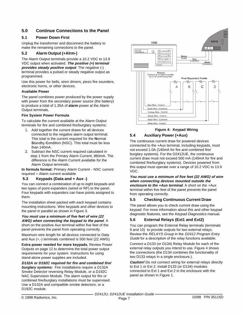
In formula format: Primary Alarm Current - NSC currentrequired = Alarm current available 5.3 Keypads (Data and + Aux -)You can connect a combination of up to eight keypads andtwo types of point expanders (wired or RF) to the panel.Four keypads with expanders can have points assigned tothem.
The installation sheet packed with each keypad containsmounting instructions. Wire keypads and other devices tothe panel in parallel as shown in Figure 3.
You must use a minimum of five feet of wire (22AWG) when connecting the keypad to the panel . Ashort on the positive Aux terminal within five feet of thepanel prevents the panel from operating correctly.
Maximum wire length for all devices connected to Dataand Aux (+,-) terminals combined is 500 feet (22 AWG).
Extra power needed for more keypads. Review PowerOutputs on page 12 to determine the total power outputrequirements for your system. Instructions for usingstand-alone power supplies are included.
D132A or D192C required for fire and combined fire/burglary systems: Fire installations require a D132ASmoke Detector reversing Relay Module, or a D192CNAC Supervision Module. The alarm output for fire orcombined fire/burglary installations must be supervised.Use a D132A and compatible smoke detectors, or aD192C module.
Figure 4: Keypad Wiring
5.4 Auxiliary Power (+Aux)The continuous current draw for powered devicesconnected to the +Aux terminal, including keypads, mustnot exceed 1.0A (140mA for fire and combined fire/burglary systems). For the D2412UE, the continuouscurrent draw must not exceed 500 mA (140mA for fire andcombined fire/burglary systems). Devices powered fromthis output must operate over a range of 10.2 VDC to 13.9VDC.
You must use a minimum of five feet (22 AWG) of wirewhen connecting devices mounted outside theenclosure to the +Aux terminal . A short on the +Auxterminal within five feet of the panel prevents the panelfrom operating correctly.
5.5 Checking Continuous Current DrawThe panel allows you to check current draw using thekeypad. For more information about this and other keypaddiagnostic features, see the Keypad Diagnostics manual.
5.6 External Relays (Ext1 and Ext2)You can program the External Relay terminals (terminals9 and 10) to provide outputs for two external relays.Review the RELAYS Group in the D2412 Program EntryGuide for a description of the relay functions available.
Connect a D133 (or D134) Relay Module for each of theexternal relay outputs you intend to use. Figure 4 showsthe connections (the D134 combines the functionality oftwo D133 relays in a single enclosure.).
Caution! Do not connect wiring for external relays directlyto Ext 1 or Ext 2. Install D133 (or D134) modulesconnected to Ext 1 and Ext 2 in the enclosure with thepanel as shown in Figure 1.
D2412U, D2412UE Installation GuidePage 810/98 P/N 35115D © 1998 Radionics, Inc.
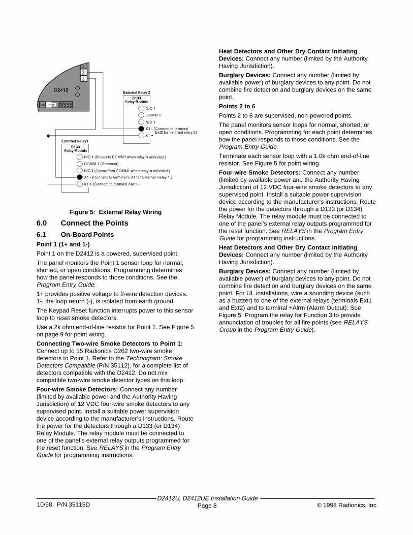
Figure 5: External Relay Wiring
6.0 Connect the Points
6.1 On-Board PointsPoint 1 (1+ and 1-)
Point 1 on the D2412 is a powered, supervised point.
The panel monitors the Point 1 sensor loop for normal,shorted, or open conditions. Programming determineshow the panel responds to those conditions. See theProgram Entry Guide.
1+ provides positive voltage to 2-wire detection devices.1-, the loop return (-), is isolated from earth ground.
The Keypad Reset function interrupts power to this sensorloop to reset smoke detectors.
Use a 2k ohm end-of-line resistor for Point 1. See Figure 5on page 9 for point wiring.
Connecting Two-wire Smoke Detectors to Point 1:Connect up to 15 Radionics D262 two-wire smokedetectors to Point 1. Refer to the Technogram: SmokeDetectors Compatible (P/N 35112), for a complete list ofdetectors compatible with the D2412. Do not mixcompatible two-wire smoke detector types on this loop.
Four-wire Smoke Detectors: Connect any number(limited by available power and the Authority HavingJurisdiction) of 12 VDC four-wire smoke detectors to anysupervised point. Install a suitable power supervisiondevice according to the manufacturer’s instructions. Routethe power for the detectors through a D133 (or D134)Relay Module. The relay module must be connected toone of the panel’s external relay outputs programmed forthe reset function. See RELAYS in the Program EntryGuide for programming instructions.
Heat Detectors and Other Dry Contact InitiatingDevices: Connect any number (limited by the AuthorityHaving Jurisdiction).
Burglary Devices: Connect any number (limited byavailable power) of burglary devices to any point. Do notcombine fire detection and burglary devices on the samepoint.
Points 2 to 6
Points 2 to 6 are supervised, non-powered points.
The panel monitors sensor loops for normal, shorted, oropen conditions. Programming for each point determineshow the panel responds to those conditions. See theProgram Entry Guide.
Terminate each sensor loop with a 1.0k ohm end-of-lineresistor. See Figure 5 for point wiring.
Four-wire Smoke Detectors: Connect any number(limited by available power and the Authority HavingJurisdiction) of 12 VDC four-wire smoke detectors to anysupervised point. Install a suitable power supervisiondevice according to the manufacturer’s instructions. Routethe power for the detectors through a D133 (or D134)Relay Module. The relay module must be connected toone of the panel’s external relay outputs programmed forthe reset function. See RELAYS in the Program EntryGuide for programming instructions.
Heat Detectors and Other Dry Contact InitiatingDevices: Connect any number (limited by the AuthorityHaving Jurisdiction).
Burglary Devices: Connect any number (limited byavailable power) of burglary devices to any point. Do notcombine fire detection and burglary devices on the samepoint. For UL installations, wire a sounding device (suchas a buzzer) to one of the external relays (terminals Ext1and Ext2) and to terminal +Alrm (Alarm Output). SeeFigure 5. Program the relay for Function 3 to provideannunciation of troubles for all fire points (see RELAYSGroup in the Program Entry Guide).
10/98 P/N 35115D© 1998 Radionics, Inc.D2412U, D2412UE Installation Guide
Page 9
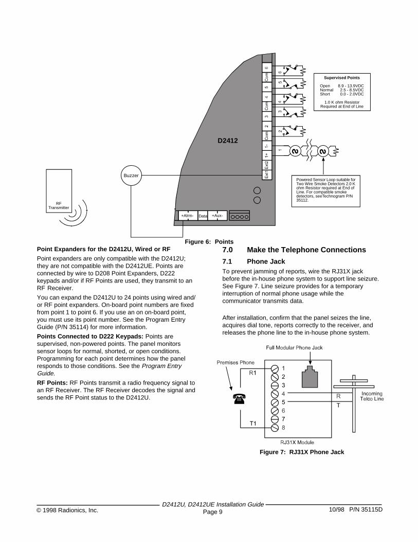
Supervised Points
Open 8.9 - 13.9VDCNormal 2.5 - 8.5VDCShort 0.0 - 2.0VDC
1.0 K ohm ResistorRequired at End of Line
RFTransmitter
Buzzer
+Alrm- Data +Aux-
D2412
Powered Sensor Loop suitable forTwo Wire Smoke Detectors 2.0 Kohm Resistor required at End ofLine. For compatible smokedetectors, seeTechnogram P/N35112.
Figure 6: PointsPoint Expanders for the D2412U, Wired or RF
Point expanders are only compatible with the D2412U;they are not compatible with the D2412UE. Points areconnected by wire to D208 Point Expanders, D222keypads and/or if RF Points are used, they transmit to anRF Receiver.
You can expand the D2412U to 24 points using wired and/or RF point expanders. On-board point numbers are fixedfrom point 1 to point 6. If you use an on on-board point,you must use its point number. See the Program EntryGuide (P/N 35114) for more information.
Points Connected to D222 Keypads: Points aresupervised, non-powered points. The panel monitorssensor loops for normal, shorted, or open conditions.Programming for each point determines how the panelresponds to those conditions. See the Program EntryGuide.
RF Points: RF Points transmit a radio frequency signal toan RF Receiver. The RF Receiver decodes the signal andsends the RF Point status to the D2412U.
7.0 Make the Telephone Connections
7.1 Phone JackTo prevent jamming of reports, wire the RJ31X jackbefore the in-house phone system to support line seizure.See Figure 7. Line seizure provides for a temporaryinterruption of normal phone usage while thecommunicator transmits data.
After installation, confirm that the panel seizes the line,acquires dial tone, reports correctly to the receiver, andreleases the phone line to the in-house phone system.
Figure 7: RJ31X Phone Jack
(
D2412U, D2412UE Installation GuidePage 1010/98 P/N 35115D © 1998 Radionics, Inc.
RAM II ResetBye does not disarm the panel
After you unlock the standby switch, the panel returns to adisarmed state. Using RAM II ResetBye , however, doesnot affect the armed state of the panel.
7.6 Check for Alarm VerificationYou must check the Alarm Verification box in thelower left hand corner of the Label if you programmedPoint 1 for Fire with Verification (Digit 1 = 2). SeePOINT CODES in the Program Entry Guide for moreinformation.
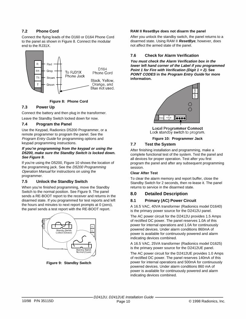
Figure 10: Programmer Jack
7.7 Test the SystemAfter finishing installation and programming, make acomplete functional test of the system. Test the panel andall devices for proper operation. Test after you firstprogram the panel and after any subsequent programmingsession.
Clear After Test
To clear the alarm memory and report buffer, close theStandby Switch for 2 seconds, then re-lease it. The panelreturns to service in the disarmed state.
8.0 Detailed Description
8.1 Primary (AC) Power CircuitA 16.5 VAC, 40VA transformer (Radionics model D1640)is the primary power source for the D2412U panel.
The AC power circuit for the D2412U provides 1.5 Ampsof rectified DC power. The panel reserves 1.0A of thispower for internal operations and 1.0A for continuouslypowered devices. Under alarm conditions 860mA ofpower is available for continuously powered and alarmindicating devices combined.
A 16.5 VAC, 25VA transformer (Radionics model D1625)is the primary power source for the D2412UE panel.
The AC power circuit for the D2412UE provides 1.0 Ampsof rectified DC power. The panel reserves 140mA of thispower for internal operations and 500mA for continuouslypowered devices. Under alarm conditions 860 mA ofpower is available for continuously powered and alarmindicating devices combined.
7.2 Phone CordConnect the flying leads of the D160 or D164 Phone Cordto the panel as shown in Figure 8. Connect the modularend to the RJ31X.
Figure 8: Phone Cord
7.3 Power UpConnect the battery and then plug in the transformer.
Leave the Standby Switch locked down for now.
7.4 Program the PanelUse the Keypad, Radionics D5200 Programmer, or aremote programmer to program the panel. See theProgram Entry Guide for programming options andkeypad programming instructions.
If you’re programming from the keypad or using theD5200, make sure the Standby Switch is locked down.See Figure 9.If you’re using the D5200, Figure 10 shows the location ofthe programming jack. See the D5200 ProgrammingOperation Manual for instructions on using theprogrammer.
7.5 Unlock the Standby SwitchWhen you’re finished programming, move the StandbySwitch to the normal position. See Figure 9. The panelsends a RE-BOOT report to the receiver and returns in thedisarmed state. If you programmed for test reports and leftthe hours and minutes to next report prompts at 0 (zero),the panel sends a test report with the RE-BOOT report.
Figure 9: Standby Switch
10/98 P/N 35115D© 1998 Radionics, Inc.D2412U, D2412UE Installation Guide
Page 11
Transient suppressors and spark gaps protect the circuitfrom power surges. This protection relies on the groundconnection. Make sure the panel’s ground terminal isconnected to a proper ground.
AC Power Failure
The panel indicates an AC power failure when power atthe terminals labeled 16.5VAC is missing for 60 seconds.The AC Fail Buzz/Rpt program item sets the panel’sresponse to detected AC failure. The panel indicates anAC power restoral 60 seconds after power restores to theterminals labeled 16.5VAC.
8.2 Secondary (DC) PowerA 12V, 7.0 Ah sealed lead-acid rechargeable battery(Radionics D126) supplies secondary power for auxiliaryand alarm outputs. The battery also powers the systemduring interruptions in primary (AC) power.
Lead Acid Batteries Only
The panel charging circuit is only calibrated for lead-acidbatteries. Do not use gel-cell or nicad batteries.
Battery Replacement
Radionics recommends battery replacement every threeto five years under normal use. Exceeding the maximumoutput ratings, or installing the transformer in an outlet thatis routinely switched off, causes heavy discharges.Routine heavy discharges can lead to premature batteryfailure.
D135A Prevents Deep Discharge: The D135A LowBattery Cutoff Module protects the battery from deepdischarge during extended power outages. Deepdischarge can cause permanent battery damage.
Battery Supervision
When the battery drops to 12.1 VDC the keypad indicatesa trouble condition. The panel transmits a BATTERY LOWreport.
When the battery voltage returns to 13.0 VDC and there isAC power at the terminals labeled 16.5VAC, the keypadreturns to normal operation. The panel transmits aBATTERY RESTORAL report.
Investigate Low Battery Reports Immediately
If primary (AC) power is off and the discharge continues,the panel becomes inoperative when the battery voltagedrops below 10.2 VDC.
If the battery is disconnected, it takes 60 seconds for thepanel to recognize the condition.
Battery Charging Circuit Float Charge
The float voltage for the battery charging circuit is 13.9VDC. Deduct any continuous load for devices connectedto the panel from 1.0A to find the maximum currentavailable for charging. At 13.9 VDC the battery is fullycharged and is maintained with a trickle charge ofapproximately 5.0mA.
Battery Discharge/Recharge Schedule (No ACPower)
Discharge Cycle:• AC OFF: The Keypad indicates trouble. AC Fail
reports if programmed.• 13.9 VDC: Charging float level.• 12.1 VDC: Low Battery reports.• 10.2 VDC: Panel shuts down below 10.2 VDC
Recharge Cycle:• AC ON: Panel restarts, battery charging begins,
AC restoral report sent.• 13.0 VDC: Battery restoral reports sent, the keypad
returns to normal operation.• 13.9 VDC: Battery float charged.
8.3 Power OutputsD2412 Circuit Protection
Two self-resetting protection devices protect the panelfrom short circuits on both the auxiliary and alarm poweroutputs.
Bell circuit protection: A short on the alarm poweroutput while the bell is ringing disables this output until ittimes out or you perform a panel reset.
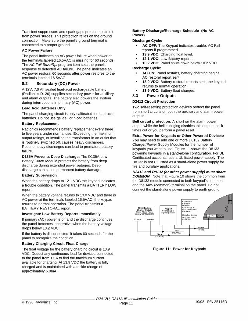
Extra Power for Keypads or Other Powered Devices:You may need to add one or more D8132 BatteryCharger/Power Supply Modules for the number ofkeypads you want to use. Figure 11 shows the D8132powering keypads in a stand-alone configuration. For ULCertificated accounts, use a UL listed power supply. TheD8132 is not UL listed as a stand-alone power supply forfire and burglary applications.
D2412 and D8132 (or other power supply) must shareCOMMON: Note that Figure 10 shows the common fromthe D8132 module connected to both keypad’s commonand the Aux- (common) terminal on the panel. Do notconnect the stand-alone power supply to earth ground.
Data +Aux-
Black(Common)
Green(Data)Red
(+12VDC)
D8132 BatteryCharger Module
(Stand-Alone PowerSupply Configuration)
+12VDC Common
KeypadConnect up to
eight in parallel.
Expanders,Keypads,D2412U:Connect up toeight devices onthe panel.
Up to four devicescan have pointsassigned.
Figure 11: Power for Keypads
D2412U, D2412UE Installation GuidePage 1210/98 P/N 35115D © 1998 Radionics, Inc.
8.5 PointsPoint Parameters
On-Board Point 1: Point 1 is a powered sensor loop.Review the Radionics Technogram: Smoke DetectorsCompatible with the D2412 (P/N 35112) for a list ofcompatible detectors. Point 1 is supervised with a 2K EOLresistor.
Points 2 to 6: Points 2 to 6 are supervised with 1.0Kresistors.
• Open Loop: Greater than 8.9 VDC, but less than13.9 VDC.
• Normal Loop: Greater than 2.5 VDC, but less than8.5 VDC.
• Shorted Loop: Greater than 0.0 VDC, but less than2.0 VDC.
Point Response TimeThe panel scans point sensor loops every 500 millisec-onds. A point must be faulted for 2 scans (one second)before the panel initiates an alarm.
8.6 KeyswitchDescription
You can connect a momentary contact arming station(keyswitch) to turn the D2412 on and off. Connect thekeyswitch to any point sensor loop.
You can use the external relay outputs and D133 (orD134) Relay Modules to activate arming status lights orkeyswitch arming stations. See the Relays section in theProgram Entry Guide.
Programming
See the POINT CODES Group in the Program EntryGuide for the correct programming for points used forkeyswitches.
Installation
Connect the end-of-line resistor for the point at thekeyswitch so that the switch shorts the resistor when itoperates. An open on the circuit produces an alarm if thearea is armed and a trouble if it is disarmed. See Figure13.
Keyswitch Operation
Shorting and restoring the point sensor loop toggles thesystem ON and OFF. All faulted points are bypassed. Seethe POINT CODES Group in the Program Entry Guide.
Silencing the Bell
To silence the bell (stop Alarm Output) if the system in ON(or part ON), operate the keyswitch to turn the systemOFF. If the area is OFF, operating the keyswitch onlysilences the bell. It does not turn the system ON.
8.4 TelephoneDialing Format
You can program the panel to use DTMF or pulse dialing.See Phone Parameters in the Program Entry Guide.
Communication Failure
After 5 attempts to reach the receiver (10 attempts if twophone numbers are programmed), the panel goes intocommunication failure. The panel clears any reports in itsphone buffer. The panel sounds a tone at the keypadindicating trouble.
Pressing the Clear key silences the tone. Whencommunication restores (a report is acknowledged by thereceiver), the keypad returns to normal operation.
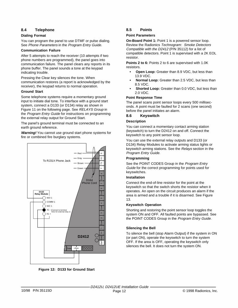
Ground Start
Some telephone systems require a momentary groundinput to initiate dial tone. To interface with a ground startsystem, connect a D133 (or D134) relay as shown inFigure 11 on the following page. See RELAYS Group inthe Program Entry Guide for instructions on programmingthe external relay output for Ground Start.
The panel’s ground terminal must be connected to anearth ground reference.
Warning! You cannot use ground start phone systems forfire or combined fire burglary systems.
Data +Aux-
N/O 1
COMM 1
N/C 1
X1 - (Connect to terminal Ext1 for external relay 1)X1 +
D133Relay Module
Brown
Green
Red
GrayTo RJ31X Phone Jack
D164Phone Cord
D2412
Figure 12: D133 for Ground Start
10/98 P/N 35115D© 1998 Radionics, Inc.D2412U, D2412UE Installation Guide
Page 13
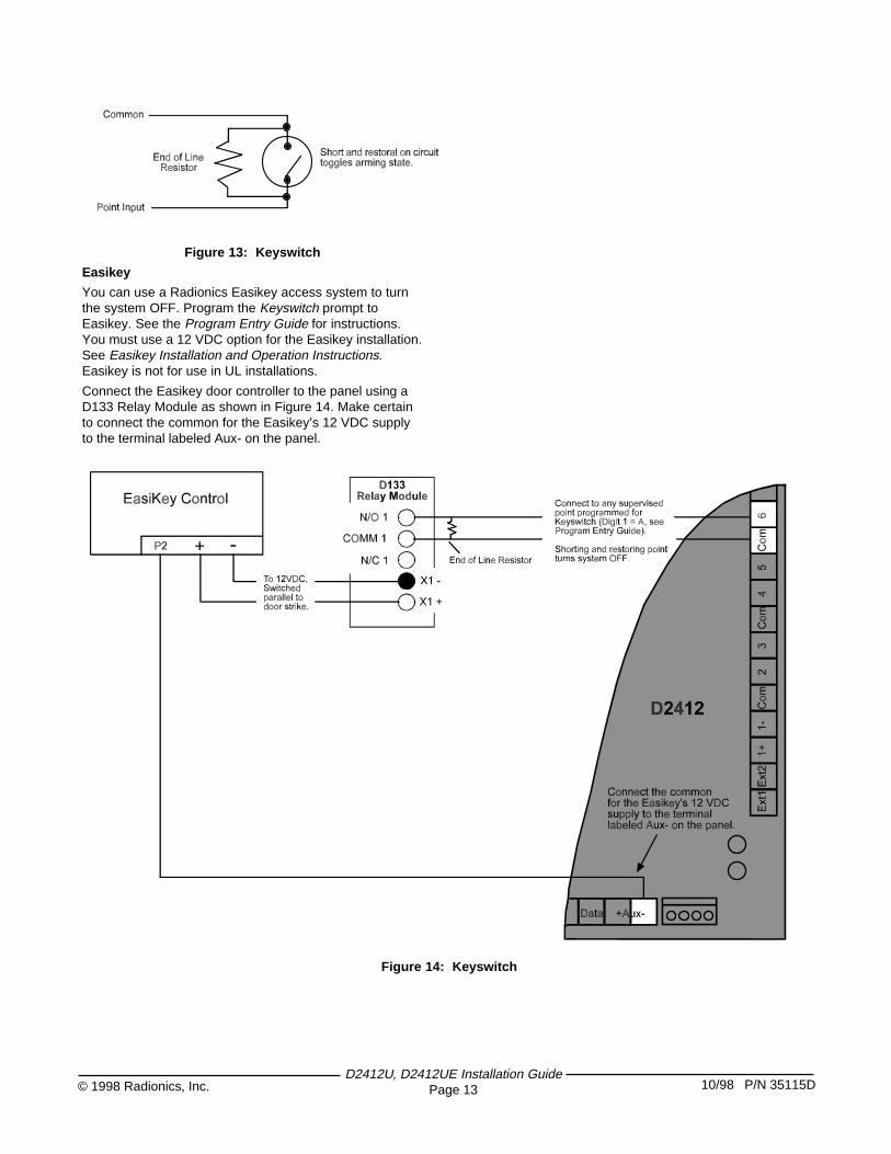
Figure 13: Keyswitch
Easikey
You can use a Radionics Easikey access system to turnthe system OFF. Program the Keyswitch prompt toEasikey. See the Program Entry Guide for instructions.You must use a 12 VDC option for the Easikey installation.See Easikey Installation and Operation Instructions.Easikey is not for use in UL installations.
Connect the Easikey door controller to the panel using aD133 Relay Module as shown in Figure 14. Make certainto connect the common for the Easikey’s 12 VDC supplyto the terminal labeled Aux- on the panel.
Figure 14: Keyswitch
D2412U, D2412UE Installation GuidePage 1410/98 P/N 35115D © 1998 Radionics, Inc.
9.0 Installation Guide for ULApplications
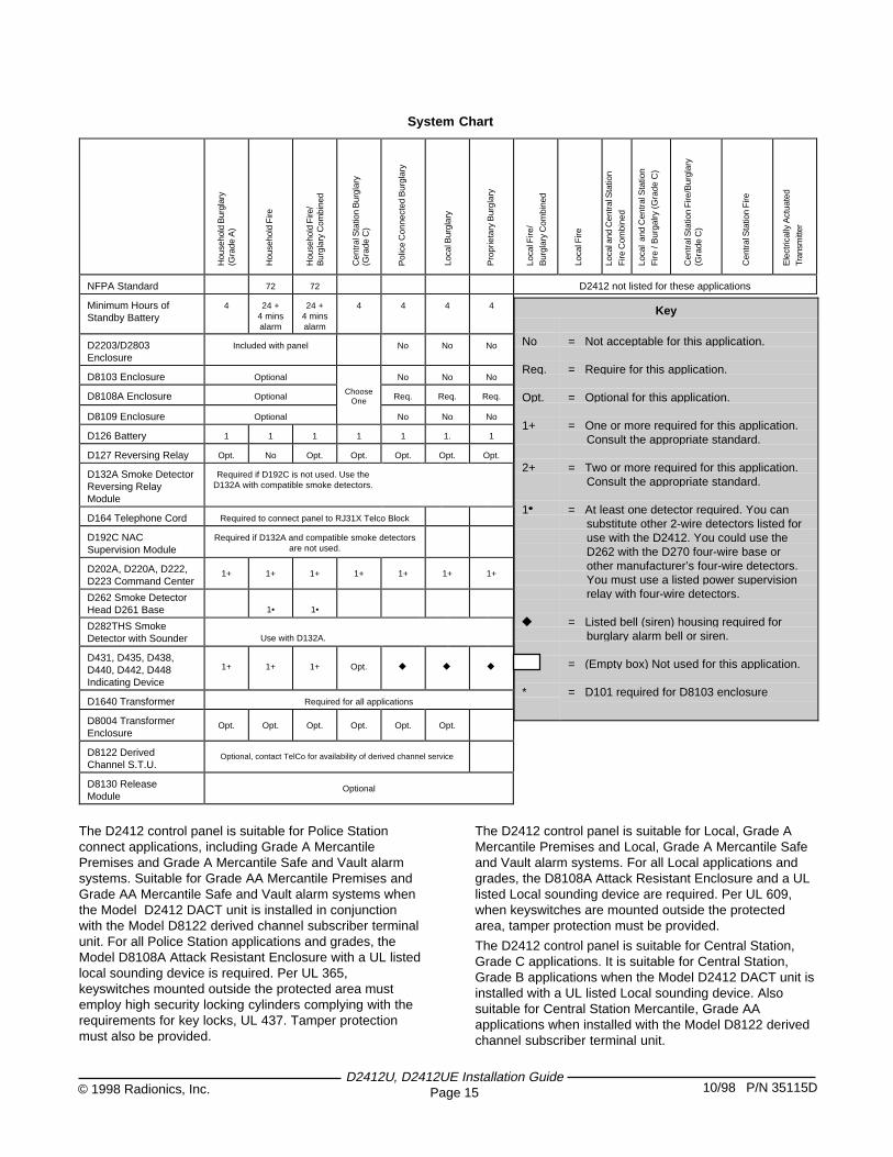
9.1 IntroductionThe System Chart references components evaluated andlisted by Underwriters’ Laboratories for compatibility withthe panel. These components meet the basic systemrequirements for the applicable standard.
The System Wiring Diagram, Issue A shows therelationship between the panel and the accessorycomponents referred to in the System Chart. See theinstallation and operation instructions for each componentfor detailed instructions.
9.2 Optional Compatible EquipmentYou can use UL listed components that do not requireevaluation for electrical compatibility in many applicationswhen installed in accordance with the manufacturer’sinstructions.
Burglary Applications
You can use UL listed burglary alarm sensors that do notrequire evaluation for electrical compatibility in burglaryapplications. In some cases you must use a UL listedRadionics interface module in conjunction with thesensors. Consult the individual component specificationand installation documents to determine suitability.
In burglary applications with one 7.0 Ah, 12 VDC battery,the panel supports an auxiliary output of 1.0A and analarm (bell) output of 1.35A configured as necessary. Foradditional loadings refer to the Current Rating Chart forStandby Battery Calculations.
For commercial burglary installations, use a maximum of45 seconds of entry delay and a maximum of 60 secondsof exit delay.
Test Weekly: UL Standard 1023 requires a weekly test.Configure the User System Test to test the battery. SeeConfiguration in the Program Entry Guide for instructions.
Fire Applications
You can use UL listed fire initiating devices not requiringelectrical compatibility evaluation in any application. Forexample: four-wire smoke detectors, heat detectors,waterflow switches, and manual pull stations are suitablefire initiating devices. Consult the individual componentspecification and installation documents to determinesuitability.
When using four-wire smoke detectors, install a suitablepower supervision unit according to the manufacturer’sinstructions. Use the D133 (or D134) Relay Module toprovide reset capability.
In fire applications with one 7.0Ah, 12 VDC battery, thepanel supports an auxiliary output of 140mA; it supports atotal combined continuous and alarm current draw duringalarm conditions of 1.0A. For additional loadings refer tothe Current Rating Chart for Standby Battery Calculations.
D132A or D192C required for fire and combined fire/burglary systems: Fire installations require a D132ASmoke Detector reversing Relay Module, or a D192CNAC Supervision Module. The alarm output for fire orcombined fire/burglary installations must be supervised.Use a D132A and compatible smoke detectors, or aD192C module.
Two-wire detectors must be electrically compatible, andmust be UL listed for use with the D2412. See theRadionics Technogram: Smoke Detectors Compatiblewith the D2412 (P/N 35112), or you may contact thedetector manufacturer.
Test Weekly: Radionics recommends testing fire andcombined fire/burglary systems weekly. Configure theUser System Test to test the battery. See Configuration inthe Program Entry Guide for instructions. For all Burglaryapplications, the panel must be programmed to send asupervisory signal to the central station a minimum ofonce every 24 hours. Do not set or program an automatictelephone dialer or similar device to place a call to a policestation number that is not specifically assigned by thatstation for such service.
Sounding Device
The sounding device shall operate for at least four minutesbefore an automatic cutoff for Household Burglaryapplications and at least 15 minutes for CommercialBurglary applications.
For all Commercial Burglary applications, the systemmust be programmed to sound the audible device everytime the system is armed.
Enclosures
The D2203 enclosure is suitable for Household Fire andBurglary applications only.
Enclosure tamper protection causing an immediate alarmsignal is required for all burglary applications.
Radionics offers three optional enclosures:
The D8103 enclosure is suitable for residential fire and/orburglary installations and commercial applications. SeeSystem Chart for acceptable applications.
The D8109 is normally used for fire alarm applications.The D8109 is approved by the Factory Mutual, CaliforniaState Fire Marshal, and the New York City Materials andEquipment Acceptance System.
The D8108A is attack resistant. It is intended primarily forUL commercial burglary and mercantile safe and vaultapplications requiring a local bell. You can use theD8108A in an burglary application where the D8103 orD8109 enclosure is suitable. The D8108A is approved bythe Factory Mutual, California State Fire Marshal, and theNew York City Materials and Equipment AcceptanceSystem.
10/98 P/N 35115D© 1998 Radionics, Inc.D2412U, D2412UE Installation Guide
Page 15
The D2412 control panel is suitable for Police Stationconnect applications, including Grade A MercantilePremises and Grade A Mercantile Safe and Vault alarmsystems. Suitable for Grade AA Mercantile Premises andGrade AA Mercantile Safe and Vault alarm systems whenthe Model D2412 DACT unit is installed in conjunctionwith the Model D8122 derived channel subscriber terminalunit. For all Police Station applications and grades, theModel D8108A Attack Resistant Enclosure with a UL listedlocal sounding device is required. Per UL 365,keyswitches mounted outside the protected area mustemploy high security locking cylinders complying with therequirements for key locks, UL 437. Tamper protectionmust also be provided.
System Chart
The D2412 control panel is suitable for Local, Grade AMercantile Premises and Local, Grade A Mercantile Safeand Vault alarm systems. For all Local applications andgrades, the D8108A Attack Resistant Enclosure and a ULlisted Local sounding device are required. Per UL 609,when keyswitches are mounted outside the protectedarea, tamper protection must be provided.
The D2412 control panel is suitable for Central Station,Grade C applications. It is suitable for Central Station,Grade B applications when the Model D2412 DACT unit isinstalled with a UL listed Local sounding device. Alsosuitable for Central Station Mercantile, Grade AAapplications when installed with the Model D8122 derivedchannel subscriber terminal unit.
Loca
l and
Cen
tral
Sta
tion
Fire
Com
bine
d
Hou
seho
ld B
urgl
ary
(Gra
de A
)
Hou
seho
ld F
ire
Hou
seho
ld F
ire/
Bur
glar
y C
ombi
ned
Cen
tral
Sta
tion
Bur
glar
y
Pol
ice
Con
nect
ed B
urgl
ary
Loca
l Bur
glar
y
Pro
prie
tary
Bur
glar
y
Loca
l Fire
/
Bur
glar
y C
ombi
ned
Loca
l Fire
Loca
l an
d C
entr
al S
tatio
n
Fire
/ B
urga
lry (
Gra
de C
)
Cen
tral
Sta
tion
Fire
/Bur
glar
y(G
rade
C)
Cen
tral
Sta
tion
Fire
Ele
ctric
ally
Act
uate
d
Tran
smitt
er
Key
No
Req.
Opt.
1+
2+
1
u
*
= Not acceptable for this application.
= Require for this application.
= Optional for this application.
= One or more required for this application.Consult the appropriate standard.
= Two or more required for this application.Consult the appropriate standard.
= At least one detector required. You cansubstitute other 2-wire detectors listed foruse with the D2412. You could use theD262 with the D270 four-wire base orother manufacturer’s four-wire detectors.You must use a listed power supervisionrelay with four-wire detectors.
= Listed bell (siren) housing required forburglary alarm bell or siren.
= (Empty box) Not used for this application.
= D101 required for D8103 enclosure
NFPA Standard 72 72 D2412 not listed for these applications
Minimum Hours ofStandby Battery
4 24 +4 minsalarm
24 +4 minsalarm
4 4 4 4
D2203/D2803Enclosure
Included with panel No No No
D8103 Enclosure Optional No No No
D8108A Enclosure OptionalChoose
One Req. Req. Req.
D8109 Enclosure Optional No No No
D126 Battery 1 1 1 1 1 1. 1
D127 Reversing Relay Opt. No Opt. Opt. Opt. Opt. Opt.
D132A Smoke DetectorReversing RelayModule
Required if D192C is not used. Use theD132A with compatible smoke detectors.
D164 Telephone Cord Required to connect panel to RJ31X Telco Block
D192C NACSupervision Module
Required if D132A and compatible smoke detectorsare not used.
D202A, D220A, D222,D223 Command Center
1+ 1+ 1+ 1+ 1+ 1+ 1+
D262 Smoke DetectorHead D261 Base 1• 1•
D282THS SmokeDetector with Sounder Use with D132A.
D431, D435, D438,D440, D442, D448Indicating Device
1+ 1+ 1+ Opt. u u u
D1640 Transformer Required for all applications
D8004 TransformerEnclosure
Opt. Opt. Opt. Opt. Opt. Opt.
D8122 DerivedChannel S.T.U.
Optional, contact TelCo for availability of derived channel service
D8130 ReleaseModule
Optional
(Gra
de C
)
D2412U, D2412UE Installation GuidePage 1610/98 P/N 35115D © 1998 Radionics, Inc.
The D2412 control panel is suitable for Proprietary BurglarAlarm, Grade C applications. Also suitable for ProprietaryBurglar Alarm, Grade B applications when Model D2412DACT unit is installed with a UL listed Local soundingdevice. Also suitable for Proprietary Burglar Alarm, GradeAA when the Model D2412 DACT unit is installed with aModel D8122 derived channel subscriber terminal unit.
The D2412 control panel is suitable for Household, GradeA applications.
UL Standard 681 for Installation and Classification ofMercantile and Bank Burglary Alarm systems requires foillining of equivalent protection of the control unit enclosure.The D8108A enclosure does not have foil lining, butacceptable protection can be provided by mountingelectronic vibration sensors inside the enclosure.
Proximity alarms (capacitance) cannot be used forthis purpose.
Install electronic vibration sensors in the D8108Aenclosure that are identical to those used to protect thesafe or the vault. Sentrol 5402, Potter EVD-S, orArrowhead S-3810 electronic vibration detection (EVD)systems which can be mounted inside the enclosure meetthe requirements of UL 681. Mount the electronic vibrationsensor directly inside the metal cabinet of the D8108A. DoNOT install the sensor within a quarter inch (1/4”) of thecomponents or traces of the printed circuit assembly.
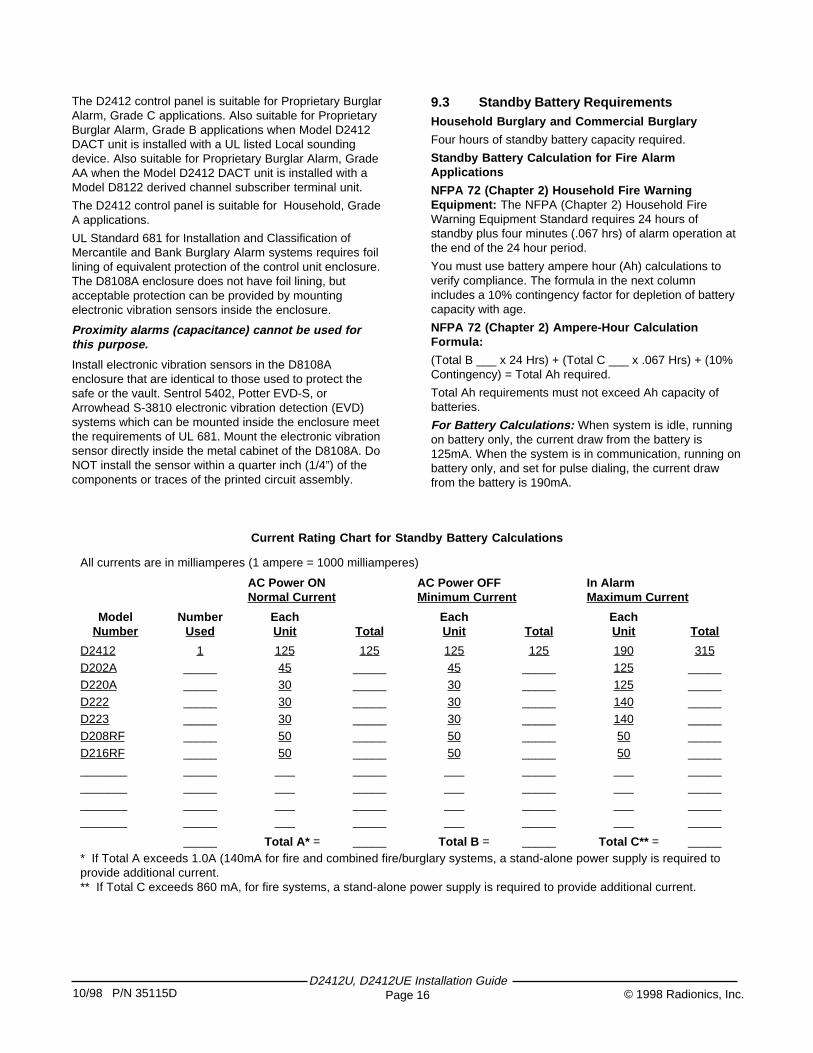
9.3 Standby Battery RequirementsHousehold Burglary and Commercial Burglary
Four hours of standby battery capacity required.
Standby Battery Calculation for Fire AlarmApplications
NFPA 72 (Chapter 2) Household Fire WarningEquipment: The NFPA (Chapter 2) Household FireWarning Equipment Standard requires 24 hours ofstandby plus four minutes (.067 hrs) of alarm operation atthe end of the 24 hour period.
You must use battery ampere hour (Ah) calculations toverify compliance. The formula in the next columnincludes a 10% contingency factor for depletion of batterycapacity with age.
NFPA 72 (Chapter 2) Ampere-Hour CalculationFormula:
(Total B ___ x 24 Hrs) + (Total C ___ x .067 Hrs) + (10%Contingency) = Total Ah required.
Total Ah requirements must not exceed Ah capacity ofbatteries.
For Battery Calculations: When system is idle, runningon battery only, the current draw from the battery is125mA. When the system is in communication, running onbattery only, and set for pulse dialing, the current drawfrom the battery is 190mA.
Current Rating Chart for Standby Battery Calculations
All currents are in milliamperes (1 ampere = 1000 milliamperes)
AC Power ONNormal Current
AC Power OFFMinimum Current
In AlarmMaximum Current
ModelNumber
NumberUsed
EachUnit Total
EachUnit Total
EachUnit Total
D2412 1 125 125 125 125 190 315D202A _____ 45 _____ 45 _____ 125 _____D220A _____ 30 _____ 30 _____ 125 _____D222 _____ 30 _____ 30 _____ 140 _____D223 _____ 30 _____ 30 _____ 140 _____D208RF _____ 50 _____ 50 _____ 50 _____D216RF _____ 50 _____ 50 _____ 50 ____________ _____ ___ _____ ___ _____ ___ ____________ _____ ___ _____ ___ _____ ___ ____________ _____ ___ _____ ___ _____ ___ ____________ _____ ___ _____ ___ _____ ___ _____
_____ Total A* = _____ Total B = _____ Total C** = _____* If Total A exceeds 1.0A (140mA for fire and combined fire/burglary systems, a stand-alone power supply is required toprovide additional current.** If Total C exceeds 860 mA, for fire systems, a stand-alone power supply is required to provide additional current.
10/98 P/N 35115D© 1998 Radionics, Inc.D2412U, D2412UE Installation Guide
Page 17
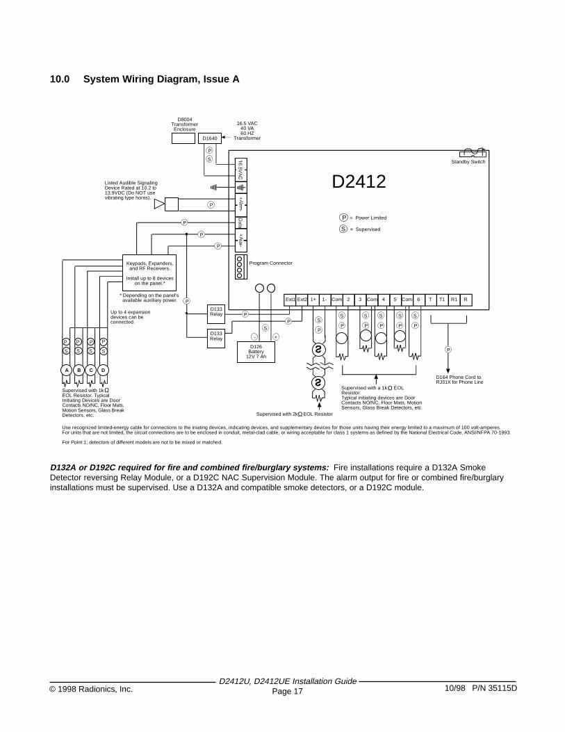
10.0 System Wiring Diagram, Issue A
D132A or D192C required for fire and combined fire/burglary systems: Fire installations require a D132A SmokeDetector reversing Relay Module, or a D192C NAC Supervision Module. The alarm output for fire or combined fire/burglaryinstallations must be supervised. Use a D132A and compatible smoke detectors, or a D192C module.
Ext1 Ext2 1+ 1- Com Com Com2 3 4 5 6 R1T1 RT
D126Battery
12V 7 Ah
Keypads, Expanders,and RF Receivers.
Install up to 8 deviceson the panel.*
Listed Audible SignalingDevice Rated at 10.2 to13.9VDC (Do NOT usevibrating type horns).
D1640
D8004TransformerEnclosure
P
S
16.5 VAC40 VA60 HZ
Transformer
+ -
S
P
P
P
P
A B C D
P P P P
S S S S
Supervised with 1kEOL Resistor. TypicalInitiating Devices are DoorContacts NO/NC, Floor Mats,Motion Sensors, Glass BreakDetectors, etc.
Ω
Up to 4 expansiondevices can beconnected.
D133Relay
D133Relay
P
P
P
S
P
S
P
S
P
S
P
S
P
S
P
Supervised with a 1k EOLResistor.Typical initiating devices are DoorContacts NO/NC, Floor Mats, MotionSensors, Glass Break Detectors, etc.
Ω
Supervised with 2k EOL ResistorΩ
Standby Switch
Program Connector
S
P = Power Limited
= Supervised
D164 Phone Cord toRJ31X for Phone Line
P
* Depending on the panel's available auxiliary power.
D2412
Use recognized limited-energy cable for connections to the iniating devices, indicating devices, and supplementary devices for those units having their energy limited to a maximum of 100 volt-amperes.For units that are not limited, the circuit connections are to be enclosed in conduit, metal-clad cable, or wiring acceptable for class 1 systems as defined by the National Electrical Code, ANSI/NFPA 70-1993.
For Point 1; detectors of different models are not to be mixed or matched.

11.0 SpecificationsPrimary Power Supply
• D2412U: 16.5 VAC 40 VA class 2 plug-in transformer(D1640)
• D2412UE: 16.5V AC 25VA class 2 plug-intransformer (D1625)
Secondary Power Supply• 12 VDC 7.0 Ah sealed lead acid rechargeable
battery.Auxiliary Power Output
• D2412U: 1.0A maximum at 10.2 VDC to 13.9 VDC fordevices powered at the Aux+ terminal (140mA forFire and combined Fire/Burglary systems.
• D2412UE: 500mA maximum at 10.2 VDC to 13.9VDC for devices powered at the Aux+ terminal(140mA for Fire and combined Fire/Burglarysystems.
Alarm Power Output• 1.35 A maximum at 10.2 VDC to 13.9 VDC output.
Output may be steady or pulsed depending onprogramming.
Fire and Fire/Burglary Systems
To comply with UL 985 listing standards for household firealarm systems (effective March 1, 1989), the totalcombined continuous and alarm current draw for thesystem during alarm conditions must be limited to860mA provided by the primary power supply (rectifiedAC).
Operating Voltage
• 10.2 VDC (minimum) 13.9 (maximum)
Telephone Connection• RJ31X or RJ38X jack interfaced with D164 phone
cord.Environmental
• Temperature: 32° - 122°F (0° - 50°C)• Relative Humidity: 5 - 85% at 86°F (30°C) non-
condensingArming Stations
• D202A Keypad• D205 Keypad• D206 Keypad• D220A Keypad• D222 Keypad• D223 Keypad• D204RF Keypad• Keychain Keypad (60-606-319.5)• Keyswitch• Easikey
Compatible Enclosures• D2203 Standard Enclosure• D2803 Standard Enclosure (D2412UE only)• D8103 Universal Enclosure• D8109 Fire Enclosure• D8108A Attack Resistant Enclosure
Compatible Accessories
See the Radionics Product Catalog for complete list.• D126 12V, 7 Ah Rechargeable Battery• D127 Reversing Relay• D132A Smoke Detector Reversing Relay Module
(Required for fire or combined fire/burglary systemsif D192C is not used. Use only with compatiblesmoke detecotrs.)
• D133 Relay Module• D134 Dual Relay Module• D135A Low Battery Cutoff Module (not UL listed)• D164 Phone Cord• D168 Telephone Arming Module• D169 2-Way Voice Verification Module
(NOT UL Listed. NOT suitable for Fire andcombined Fire/Burglary installations. NOT suitablefor UL Certificated Burglary installations)
• D192C NAC Supervision Module (required if D132Ais not used)
• D202A Keypad• D204RF Keypad (not UL listed)• D208 RF Receiver• D216 RF Receiver• D220A Keypad• D222 Keypad• D223 Keypad• D250 Heat Detector Base• D254 135° Fixed Point Thermostat• D255 190° Fixed Point Thermostat• D261A Smoke Detector Base• D262 Smoke Detector Head• D440 (6”), D442 (10”) Bells• D448 12 VDC Horn• D1640 16.5 VAC 40 VA Transformer• D5200 Programmer• D5300 Remote Account Manager II• D8004 Transformer Enclosure• D8121A/D8122 Derived Channel S.T.U. (use D8122
for UL systems)• D282THS Smoke Detector with Sounder D282TH D282• Easikey (not for use in UL systems)
D2412U, D2412UE Installation Guide10/98 P/N 35115D © 1998 Radionics, Inc.Page 18
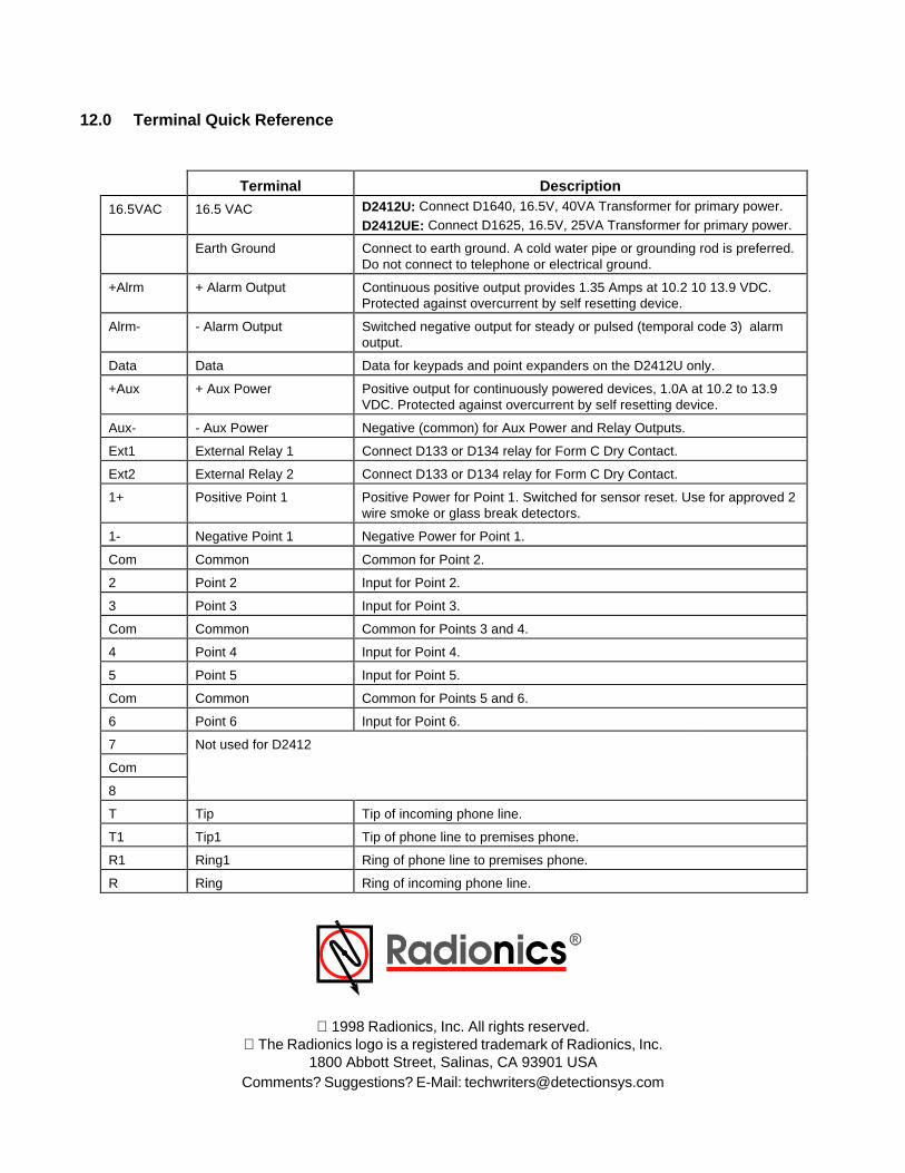
12.0 Terminal Quick Reference
1998 Radionics, Inc. All rights reserved. The Radionics logo is a registered trademark of Radionics, Inc.
1800 Abbott Street, Salinas, CA 93901 USAComments? Suggestions? E-Mail: [email protected]
Terminal Description
16.5VAC 16.5 VAC D2412U: Connect D1640, 16.5V, 40VA Transformer for primary power.
D2412UE: Connect D1625, 16.5V, 25VA Transformer for primary power.
Earth Ground Connect to earth ground. A cold water pipe or grounding rod is preferred.Do not connect to telephone or electrical ground.
+Alrm + Alarm Output Continuous positive output provides 1.35 Amps at 10.2 10 13.9 VDC.Protected against overcurrent by self resetting device.
Alrm- - Alarm Output Switched negative output for steady or pulsed (temporal code 3) alarmoutput.
Data Data Data for keypads and point expanders on the D2412U only.
+Aux + Aux Power Positive output for continuously powered devices, 1.0A at 10.2 to 13.9VDC. Protected against overcurrent by self resetting device.
Aux- - Aux Power Negative (common) for Aux Power and Relay Outputs.
Ext1 External Relay 1 Connect D133 or D134 relay for Form C Dry Contact.
Ext2 External Relay 2 Connect D133 or D134 relay for Form C Dry Contact.
1+ Positive Point 1 Positive Power for Point 1. Switched for sensor reset. Use for approved 2wire smoke or glass break detectors.
1- Negative Point 1 Negative Power for Point 1.
Com Common Common for Point 2.
2 Point 2 Input for Point 2.
3 Point 3 Input for Point 3.
Com Common Common for Points 3 and 4.
4 Point 4 Input for Point 4.
5 Point 5 Input for Point 5.
Com Common Common for Points 5 and 6.
6 Point 6 Input for Point 6.
7 Not used for D2412
Com
8
T Tip Tip of incoming phone line.
T1 Tip1 Tip of phone line to premises phone.
R1 Ring1 Ring of phone line to premises phone.
R Ring Ring of incoming phone line.