Embed Size (px)
Citation preview
D2071A Fire Control/Communicator
Operation and Installation Manual
A member of the Bosch Group
12
5
6789
10
12131415161718
34
11
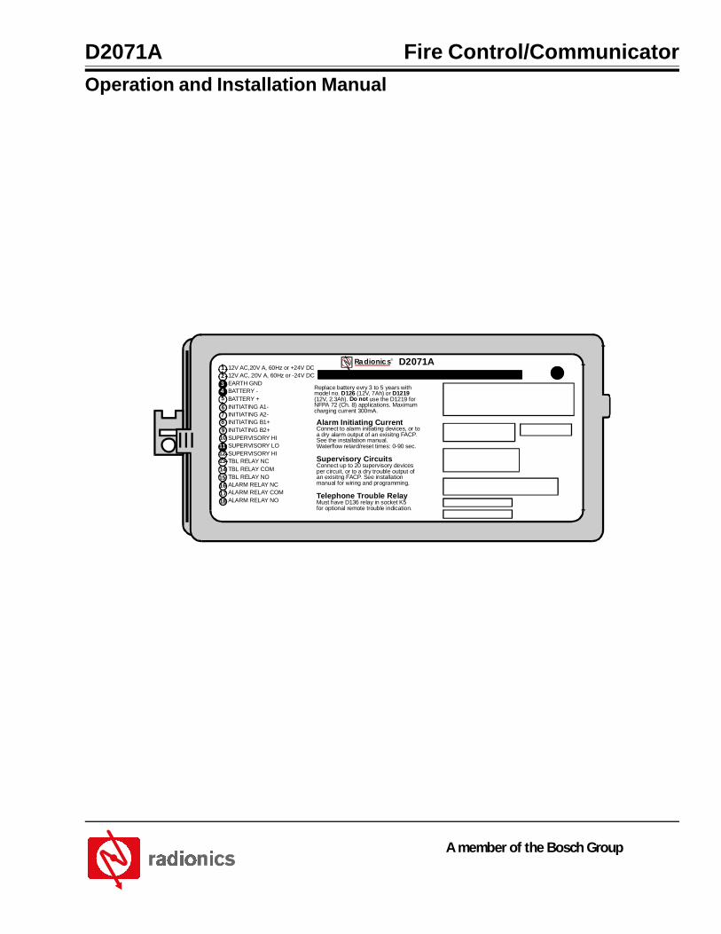
12V AC,20V A, 60Hz or +24V DC12V AC, 20V A, 60Hz or -24V DCEARTH GNDBATTERY -BATTERY +INITIATING A1-INITIATING A2-INITIATING B1+INITIATING B2+SUPERVISORY HISUPERVISORY LOSUPERVISORY HITBL RELAY NCTBL RELAY COMTBL RELAY NOALARM RELAY NCALARM RELAY COMALARM RELAY NO
Replace battery evry 3 to 5 years withmodel no. D126 (12V, 7Ah) or D1219(12V, 2.3Ah). Do not use the D1219 forNFPA 72 (Ch. 8) applications. Maximumcharging current 300mA.
Alarm Initiating CurrentConnect to alarm initiating devices, or toa dry alarm output of an exisitng FACP.See the installation manual.Waterflow retard/reset times: 0-90 sec.
Supervisory CircuitsConnect up to 20 supervisory devicesper circuit, or to a dry trouble output ofan exisitng FACP. See installationmanual for wiring and programming.
Telephone Trouble RelayMust have D136 relay in socket K5for optional remote trouble indication.
®Radionics D2071A

D2071A
D2071AOperation & Installation Manual74-06200-000-D Page 2 Copyright © 2001 Radionics
This page is intentionally blank
D2071A
D2071A Operation & Installation ManualCopyright © 2001 Radionics Page 3 74-06200-000-D
Contents
Contents
1.0 FCC Notice ........................................................................................................................................................................... 72.0 D2071A Overview ............................................................................................................................................................... 92.1 Introduction ........................................................................................................................................................................... 92.2 Communicator ....................................................................................................................................................................... 92.3 RFI/Lightning Protection ....................................................................................................................................................... 92.4 Materials Included ................................................................................................................................................................ 92.4.1 D2071A ................................................................................................................................................................................. 92.4.2 D2071AC ............................................................................................................................................................................... 92.5 Materials Needed ............................................................................................................................................................... 102.6 Listings and Approvals ....................................................................................................................................................... 102.6.1 Mandatory Connections ..................................................................................................................................................... 102.7 Slave Communicator Applications ..................................................................................................................................... 112.7.1 Power for Slave Applications .............................................................................................................................................. 112.7.2 Listed Enclosure Required ................................................................................................................................................. 112.8 Receiving Equipment ......................................................................................................................................................... 122.9 D2071A Control/Communicator Assembly ....................................................................................................................... 122.9.1 Enclosure ............................................................................................................................................................................ 122.9.2 Phone Line Trouble Relay (K5) .......................................................................................................................................... 132.9.3 Initiating Circuit Alarm Relay (K6) ..................................................................................................................................... 132.9.4 Primary Modular Phone Jack ............................................................................................................................................. 132.9.5 Alternate Modular Phone Jack ........................................................................................................................................... 132.9.6 Phone Line Trouble Buzzer ................................................................................................................................................ 132.9.7 Phone Line Trouble (Phone Fail) LED (Yellow) ................................................................................................................. 132.9.8 Programmer Connector (J3) .............................................................................................................................................. 132.9.9 Terminal Strip ...................................................................................................................................................................... 132.9.10 Strain Relief Tab .................................................................................................................................................................. 132.9.11 Mounting Tabs ..................................................................................................................................................................... 133.0 D2071A Installation .......................................................................................................................................................... 153.1 Before You Begin ................................................................................................................................................................ 163.2 Earth Ground Wiring ........................................................................................................................................................... 163.2.1 12 VAC Mode ...................................................................................................................................................................... 163.2.2 24 VDC Mode ...................................................................................................................................................................... 163.3 Zone 1, Alarm Initiating Circuit .......................................................................................................................................... 163.3.1 Description .......................................................................................................................................................................... 163.3.2 Class A (NFPA Style D) Circuit Parameters ...................................................................................................................... 163.3.3 Retard and Reset Times .................................................................................................................................................... 173.3.4 Wiring .................................................................................................................................................................................. 173.3.4.1 Stand-Alone Applications ................................................................................................................................................... 173.3.4.2 Slave Communicator Applications ..................................................................................................................................... 173.4 Zones 2 and 3, Supervisory Circuits ................................................................................................................................. 183.4.1 Description .......................................................................................................................................................................... 183.4.1.1 Mode 1 and Mode 2 Restrictions ....................................................................................................................................... 183.4.2 Wiring .................................................................................................................................................................................. 183.4.2.1 Stand-alone Applications ................................................................................................................................................... 18
D2071A
D2071AOperation & Installation Manual74-06200-000-D Page 4 Copyright © 2001 Radionics
3.4.2.2 Slave Communicator Applications ..................................................................................................................................... 183.4.3 Class B (NFPA Style A) Circuit Parameters ...................................................................................................................... 183.5 Initiating Circuit Alarm Relay .............................................................................................................................................. 203.5.1 Description .......................................................................................................................................................................... 203.5.2 Relay Installation ................................................................................................................................................................ 203.5.3 Relay Wiring ........................................................................................................................................................................ 203.6 Phone Line Trouble Relay .................................................................................................................................................. 213.6.1 Description .......................................................................................................................................................................... 213.6.2 Relay Installation ................................................................................................................................................................ 213.6.3 Relay Wiring ........................................................................................................................................................................ 213.7 Primary Power Supply ........................................................................................................................................................ 213.7.1 12 VAC Mode ...................................................................................................................................................................... 213.7.2 24 VDC Mode ...................................................................................................................................................................... 223.7.2.1 24 VDC Battery Discharge/Recharge Schedule ............................................................................................................... 223.8 Secondary Power Supply and Charging Circuit (12 VAC Mode Only) ............................................................................ 223.8.1 Battery ................................................................................................................................................................................. 223.8.2 Battery Installation .............................................................................................................................................................. 223.8.3 Battery Replacement .......................................................................................................................................................... 223.8.4 Battery Supervision ............................................................................................................................................................ 223.8.5 Battery Charging Circuit ..................................................................................................................................................... 233.8.5.1 12 VAC Battery Discharge/Recharge Schedule ............................................................................................................... 233.9 Telephone Connections ...................................................................................................................................................... 233.9.1 Telephone Cord Installation ............................................................................................................................................... 233.9.2 Location ............................................................................................................................................................................... 233.9.3 Telephone Line Supervision ............................................................................................................................................... 243.9.4 Call Routing ........................................................................................................................................................................ 243.9.5 Notification .......................................................................................................................................................................... 253.10 Cable Tie Installation .......................................................................................................................................................... 253.11 D2071A Mounting ............................................................................................................................................................... 263.11.1 Screw Mounting .................................................................................................................................................................. 263.11.2 D2002 Mounting Plate ........................................................................................................................................................ 263.11.3 Adhesive Strip Mounting .................................................................................................................................................... 263.12 End User Instruction Label ................................................................................................................................................ 264.0 D2071A Programming ...................................................................................................................................................... 274.1 Description .......................................................................................................................................................................... 274.2 Navigating Through Handlers and Program Records ...................................................................................................... 274.3 Function Keys ..................................................................................................................................................................... 274.4 Data Keys ............................................................................................................................................................................ 274.5 Helpful Tones ...................................................................................................................................................................... 284.6 Editing a Record ................................................................................................................................................................. 284.7 Programmer Connection .................................................................................................................................................... 284.8 Entering the 2071 Handler ................................................................................................................................................. 284.9 Program Modules ............................................................................................................................................................... 284.10 How to Edit the Program Record ....................................................................................................................................... 295.0 2071 Program Record ...................................................................................................................................................... 315.1 Account # ............................................................................................................................................................................ 315.2 Transmit BFSK .................................................................................................................................................................... 315.3 DTMF Dialing ...................................................................................................................................................................... 315.4 PriPre ................................................................................................................................................................................... 315.5 PriPh# .................................................................................................................................................................................. 315.6 AltPri .................................................................................................................................................................................... 325.7 AltPh# .................................................................................................................................................................................. 325.8 12 Volt Mode ....................................................................................................................................................................... 325.9 Class B Mode ...................................................................................................................................................................... 325.10 Retard Time ......................................................................................................................................................................... 325.11 Reset Time .......................................................................................................................................................................... 335.12 Hrs Til Rpt ........................................................................................................................................................................... 335.13 Mins Til Rpt ......................................................................................................................................................................... 33
Contents
D2071A
D2071A Operation & Installation ManualCopyright © 2001 Radionics Page 5 74-06200-000-D
6.0 Receiver Reports .............................................................................................................................................................. 356.1 ALARM ZN 1 ....................................................................................................................................................................... 356.2 ALARM ZN 2 ....................................................................................................................................................................... 356.3 ALARM ZN 3 ....................................................................................................................................................................... 356.4 RESTORAL ZN 1 ................................................................................................................................................................ 356.5 RESTORAL ZN 2 ................................................................................................................................................................ 356.6 RESTORAL ZN 3 ................................................................................................................................................................ 356.7 RESTORAL ZN 9 ................................................................................................................................................................ 356.8 RESTORAL ZN B ............................................................................................................................................................... 356.9 RESTORAL ZN C ............................................................................................................................................................... 356.10 RESTORAL ZN E ............................................................................................................................................................... 356.11 TROUBLE ZN 1 .................................................................................................................................................................. 356.12 TROUBLE ZN 2 .................................................................................................................................................................. 356.13 TROUBLE ZN 3 .................................................................................................................................................................. 366.14 TROUBLE ZN 9 .................................................................................................................................................................. 366.15 TROUBLE ZN B .................................................................................................................................................................. 366.16 TROUBLE ZN C .................................................................................................................................................................. 366.17 TROUBLE ZN E .................................................................................................................................................................. 367.0 Troubleshooting Guide .................................................................................................................................................... 377.1 Introduction ......................................................................................................................................................................... 377.2 Phone Line Trouble Buzzer, LED, and Relay Activated .................................................................................................... 377.2.1 Phone Line Trouble ............................................................................................................................................................. 377.2.2 Communications Failure ..................................................................................................................................................... 377.3 Trouble Zone E .................................................................................................................................................................... 387.4 Problems Programming with the D5200 Programmer ...................................................................................................... 387.5 Problems with the Zones (Alarm Initiating and Supervisory Circuits) ............................................................................. 397.6 Trouble Zone 9 .................................................................................................................................................................... 397.6.1 12 VAC Mode (Battery and Transformer) .......................................................................................................................... 397.6.2 24 VDC Mode (Connection to FACP) ................................................................................................................................ 398.0 Specifications .................................................................................................................................................................... 41
Contents
D2071A
D2071AOperation & Installation Manual74-06200-000-D Page 6 Copyright © 2001 Radionics
Figures and Tables
Figures
Figure 1: D2071A Control/Communicator ........................................................................................................................................ 12
Figure 2: Stand-Alone Installation .................................................................................................................................................... 15
Figure 3: Slave Communicator Installation ...................................................................................................................................... 15
Figure 4: Modes 1, 2 and 3 ............................................................................................................................................................... 19
Figure 5: Relay Sockets .................................................................................................................................................................... 20
Figure 6: RJ31X Wiring ..................................................................................................................................................................... 23
Figure 7: Insert the Cable Tie ........................................................................................................................................................... 25
Figure 8: Secure the Cable Tie and Wires ....................................................................................................................................... 25
Figure 9: Navigating the 2071 Program ........................................................................................................................................... 29
Tables
Table 1: Mandatory Connections for NFPA 72 Central Station and NFPA 72 Remote Station ..................................................... 11
Table 2: 24 VDC Battery Discharge/Recharge Schedule ................................................................................................................ 22
Table 3: 12 VAC Battery Discharge/Recharge Schedule ................................................................................................................ 23
Table 4: Call Routing Assignments ................................................................................................................................................... 24
Table 5: Special Dialing Characters .................................................................................................................................................. 31
D2071A
D2071A Operation & Installation ManualCopyright © 2001 Radionics Page 7 74-06200-000-D
1.0 FCC NoticeThis equipment generates, uses and can radiate radio frequency energy. If not installed in accordance with themanufacturer’s instructions, it may cause interference to radio communications. It has been tested and found to complywith the specifications in Subpart J of Part 15 of FCC Rules for Class B Computing Devices.
If this equipment causes interference to radio or television reception -- which can be determined by turning the equipmenton and off -- the installer is encouraged to correct the interference by one or more of the following measures: 1)Reorient the antenna of the radio/television, 2) Connect the AC transformer to a different outlet so the control panel andradio/television are on different branch circuits, 3) Relocate the control panel with respect to the radio/television.
If necessary, the installer should consult an experienced radio/television technician for additional suggestions, or sendfor the “Interference Handbook” prepared by the Federal Communications Commission. This booklet is available fromthe U.S. Government Printing Office, Washington D.C. 20402, stock no. 004-000-00450-7.
The D2071A Control/Communicator is registered with the Federal Communications Commission under part 68, forconnection to the public telephone network using an RJ31X or RJ38X jack installed by your local telephone company.
• FCC Registration Number: AJ9USA-61104-AL-E
• Ringer Equivalence: 0.0B (AC)
1.3B (DC)
FCC Notice
D2071A
D2071AOperation & Installation Manual74-06200-000-D Page 8 Copyright © 2001 Radionics
FCC Notice
Notes:
D2071A
D2071A Operation & Installation ManualCopyright © 2001 Radionics Page 9 74-06200-000-D
2.0 D2071A Overview2.1 Introduction
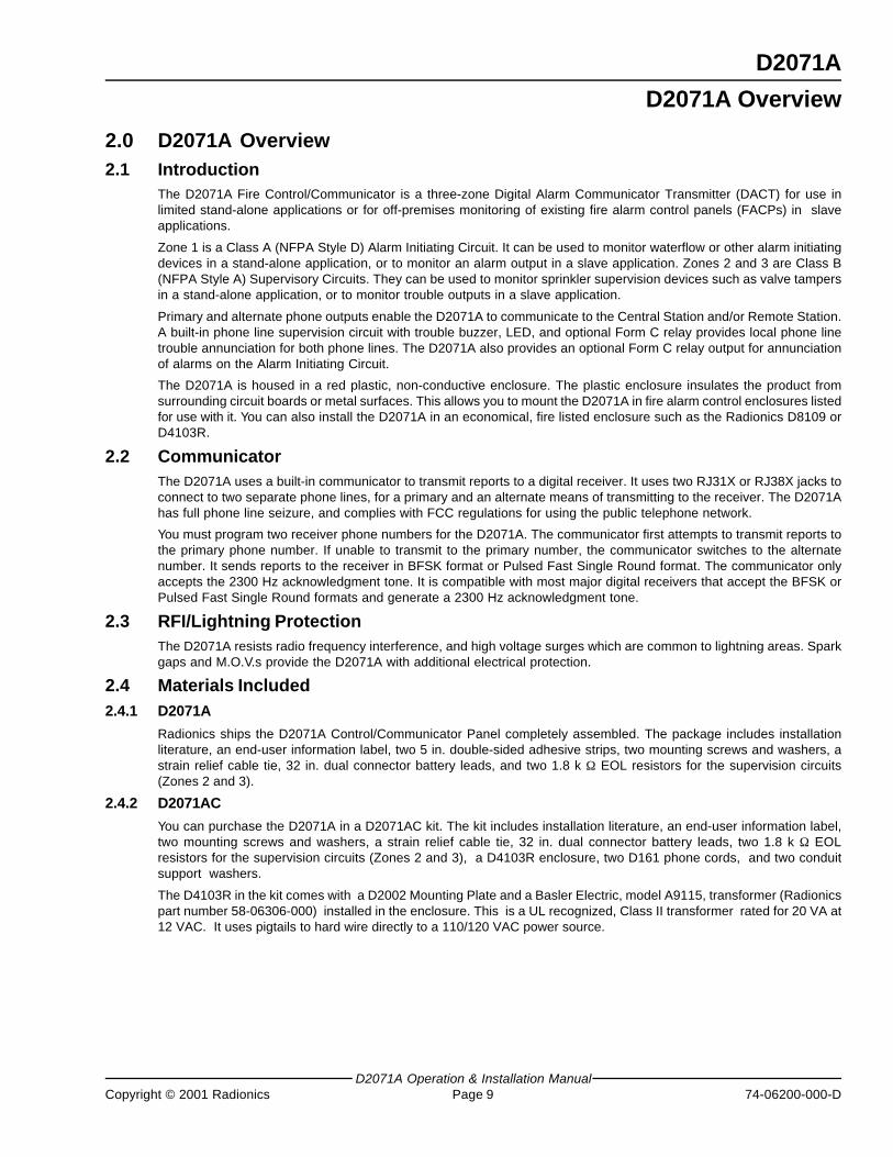
The D2071A Fire Control/Communicator is a three-zone Digital Alarm Communicator Transmitter (DACT) for use inlimited stand-alone applications or for off-premises monitoring of existing fire alarm control panels (FACPs) in slaveapplications.
Zone 1 is a Class A (NFPA Style D) Alarm Initiating Circuit. It can be used to monitor waterflow or other alarm initiatingdevices in a stand-alone application, or to monitor an alarm output in a slave application. Zones 2 and 3 are Class B(NFPA Style A) Supervisory Circuits. They can be used to monitor sprinkler supervision devices such as valve tampersin a stand-alone application, or to monitor trouble outputs in a slave application.
Primary and alternate phone outputs enable the D2071A to communicate to the Central Station and/or Remote Station.A built-in phone line supervision circuit with trouble buzzer, LED, and optional Form C relay provides local phone linetrouble annunciation for both phone lines. The D2071A also provides an optional Form C relay output for annunciationof alarms on the Alarm Initiating Circuit.
The D2071A is housed in a red plastic, non-conductive enclosure. The plastic enclosure insulates the product fromsurrounding circuit boards or metal surfaces. This allows you to mount the D2071A in fire alarm control enclosures listedfor use with it. You can also install the D2071A in an economical, fire listed enclosure such as the Radionics D8109 orD4103R.
2.2 CommunicatorThe D2071A uses a built-in communicator to transmit reports to a digital receiver. It uses two RJ31X or RJ38X jacks toconnect to two separate phone lines, for a primary and an alternate means of transmitting to the receiver. The D2071Ahas full phone line seizure, and complies with FCC regulations for using the public telephone network.
You must program two receiver phone numbers for the D2071A. The communicator first attempts to transmit reports tothe primary phone number. If unable to transmit to the primary number, the communicator switches to the alternatenumber. It sends reports to the receiver in BFSK format or Pulsed Fast Single Round format. The communicator onlyaccepts the 2300 Hz acknowledgment tone. It is compatible with most major digital receivers that accept the BFSK orPulsed Fast Single Round formats and generate a 2300 Hz acknowledgment tone.
2.3 RFI/Lightning ProtectionThe D2071A resists radio frequency interference, and high voltage surges which are common to lightning areas. Sparkgaps and M.O.V.s provide the D2071A with additional electrical protection.
2.4 Materials Included2.4.1 D2071A
Radionics ships the D2071A Control/Communicator Panel completely assembled. The package includes installationliterature, an end-user information label, two 5 in. double-sided adhesive strips, two mounting screws and washers, astrain relief cable tie, 32 in. dual connector battery leads, and two 1.8 k Ω EOL resistors for the supervision circuits(Zones 2 and 3).
2.4.2 D2071AC
You can purchase the D2071A in a D2071AC kit. The kit includes installation literature, an end-user information label,two mounting screws and washers, a strain relief cable tie, 32 in. dual connector battery leads, two 1.8 k Ω EOLresistors for the supervision circuits (Zones 2 and 3), a D4103R enclosure, two D161 phone cords, and two conduitsupport washers.
The D4103R in the kit comes with a D2002 Mounting Plate and a Basler Electric, model A9115, transformer (Radionicspart number 58-06306-000) installed in the enclosure. This is a UL recognized, Class II transformer rated for 20 VA at12 VAC. It uses pigtails to hard wire directly to a 110/120 VAC power source.
D2071A Overview
D2071A
D2071AOperation & Installation Manual74-06200-000-D Page 10 Copyright © 2001 Radionics
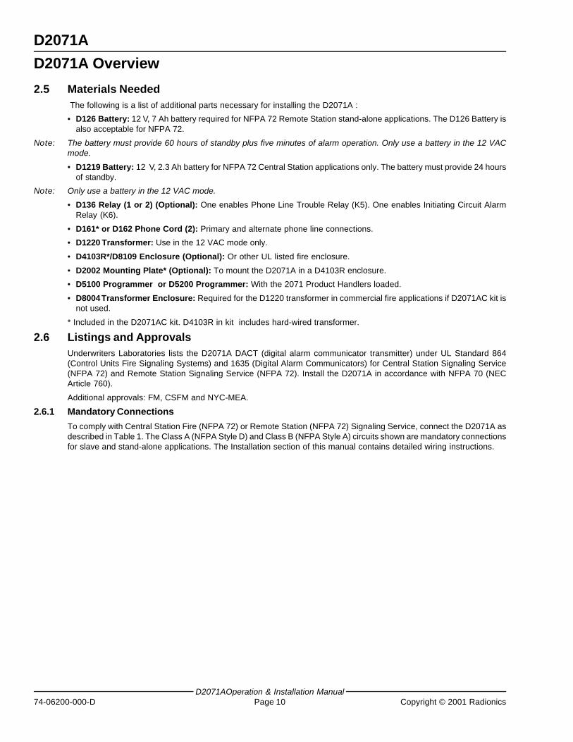
2.5 Materials Needed The following is a list of additional parts necessary for installing the D2071A :
• D126 Battery: 12 V, 7 Ah battery required for NFPA 72 Remote Station stand-alone applications. The D126 Battery isalso acceptable for NFPA 72.
Note: The battery must provide 60 hours of standby plus five minutes of alarm operation. Only use a battery in the 12 VACmode.
• D1219 Battery: 12 V, 2.3 Ah battery for NFPA 72 Central Station applications only. The battery must provide 24 hoursof standby.
Note: Only use a battery in the 12 VAC mode.
• D136 Relay (1 or 2) (Optional): One enables Phone Line Trouble Relay (K5). One enables Initiating Circuit AlarmRelay (K6).
• D161* or D162 Phone Cord (2): Primary and alternate phone line connections.
• D1220 Transformer: Use in the 12 VAC mode only.
• D4103R*/D8109 Enclosure (Optional): Or other UL listed fire enclosure.
• D2002 Mounting Plate* (Optional): To mount the D2071A in a D4103R enclosure.
• D5100 Programmer or D5200 Programmer: With the 2071 Product Handlers loaded.
• D8004 Transformer Enclosure: Required for the D1220 transformer in commercial fire applications if D2071AC kit isnot used.
* Included in the D2071AC kit. D4103R in kit includes hard-wired transformer.
2.6 Listings and ApprovalsUnderwriters Laboratories lists the D2071A DACT (digital alarm communicator transmitter) under UL Standard 864(Control Units Fire Signaling Systems) and 1635 (Digital Alarm Communicators) for Central Station Signaling Service(NFPA 72) and Remote Station Signaling Service (NFPA 72). Install the D2071A in accordance with NFPA 70 (NECArticle 760).
Additional approvals: FM, CSFM and NYC-MEA.
2.6.1 Mandatory Connections
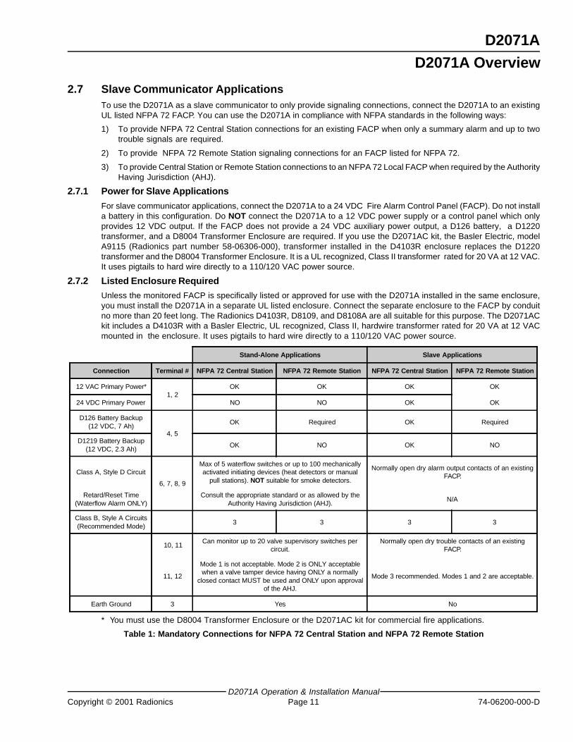
To comply with Central Station Fire (NFPA 72) or Remote Station (NFPA 72) Signaling Service, connect the D2071A asdescribed in Table 1. The Class A (NFPA Style D) and Class B (NFPA Style A) circuits shown are mandatory connectionsfor slave and stand-alone applications. The Installation section of this manual contains detailed wiring instructions.
D2071A Overview
D2071A
D2071A Operation & Installation ManualCopyright © 2001 Radionics Page 11 74-06200-000-D
2.7 Slave Communicator ApplicationsTo use the D2071A as a slave communicator to only provide signaling connections, connect the D2071A to an existingUL listed NFPA 72 FACP. You can use the D2071A in compliance with NFPA standards in the following ways:
1) To provide NFPA 72 Central Station connections for an existing FACP when only a summary alarm and up to twotrouble signals are required.
2) To provide NFPA 72 Remote Station signaling connections for an FACP listed for NFPA 72.
3) To provide Central Station or Remote Station connections to an NFPA 72 Local FACP when required by the AuthorityHaving Jurisdiction (AHJ).
2.7.1 Power for Slave Applications
For slave communicator applications, connect the D2071A to a 24 VDC Fire Alarm Control Panel (FACP). Do not installa battery in this configuration. Do NOT connect the D2071A to a 12 VDC power supply or a control panel which onlyprovides 12 VDC output. If the FACP does not provide a 24 VDC auxiliary power output, a D126 battery, a D1220transformer, and a D8004 Transformer Enclosure are required. If you use the D2071AC kit, the Basler Electric, modelA9115 (Radionics part number 58-06306-000), transformer installed in the D4103R enclosure replaces the D1220transformer and the D8004 Transformer Enclosure. It is a UL recognized, Class II transformer rated for 20 VA at 12 VAC.It uses pigtails to hard wire directly to a 110/120 VAC power source.
2.7.2 Listed Enclosure Required
Unless the monitored FACP is specifically listed or approved for use with the D2071A installed in the same enclosure,you must install the D2071A in a separate UL listed enclosure. Connect the separate enclosure to the FACP by conduitno more than 20 feet long. The Radionics D4103R, D8109, and D8108A are all suitable for this purpose. The D2071ACkit includes a D4103R with a Basler Electric, UL recognized, Class II, hardwire transformer rated for 20 VA at 12 VACmounted in the enclosure. It uses pigtails to hard wire directly to a 110/120 VAC power source.
Stand-Alone Applications Slave Applications
Connection Terminal # NFPA 72 Central Station NFPA 72 Remote Station NFPA 72 Central Station NFPA 72 Remote Station
12 VAC Primary Power*1, 2
OK OK OK OK
24 VDC Primary Power NO NO OK OK
D126 Battery Backup(12 VDC, 7 Ah)
4, 5
OK Required OK Required
D1219 Battery Backup(12 VDC, 2.3 Ah)
OK NO OK NO
Class A, Style D Circuit
6, 7, 8, 9
Max of 5 waterflow switches or up to 100 mechanicallyactivated initiating devices (heat detectors or manual
pull stations). NOT suitable for smoke detectors.
Normally open dry alarm output contacts of an existingFACP.
Retard/Reset Time(Waterflow Alarm ONLY)
Consult the appropriate standard or as allowed by theAuthority Having Jurisdiction (AHJ).
N/A
Class B, Style A Circuits(Recommended Mode)
3 3 3 3
10, 11Can monitor up to 20 valve supervisory switches per
circuit.Normally open dry trouble contacts of an existing
FACP.
11, 12
Mode 1 is not acceptable. Mode 2 is ONLY acceptablewhen a valve tamper device having ONLY a normally
closed contact MUST be used and ONLY upon approvalof the AHJ.
Mode 3 recommended. Modes 1 and 2 are acceptable.
Earth Ground 3 Yes No
* You must use the D8004 Transformer Enclosure or the D2071AC kit for commercial fire applications.
Table 1: Mandatory Connections for NFPA 72 Central Station and NFPA 72 Remote Station
D2071A Overview
D2071A
D2071AOperation & Installation Manual74-06200-000-D Page 12 Copyright © 2001 Radionics
2.8 Receiving EquipmentThe D2071A must report to compatible, UL listed receiving equipment that meets the following processing capabilities:
• Fire Alarm
• System Trouble
• Low Battery
• 24 Hour Test
• System Restoral
• 2300 Hz Acknowledgment Tone
• Radioncs BFSK or 3x1, 40 pulse-per-second, single round with parity (Radionics superfast)
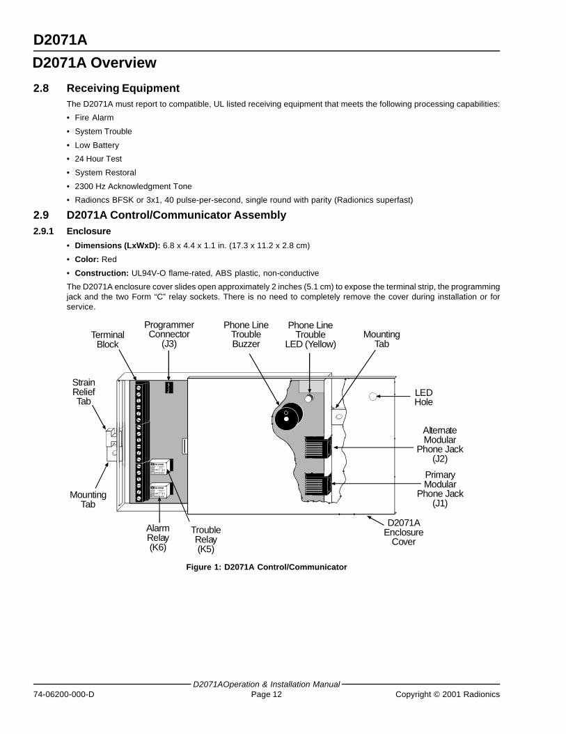
2.9 D2071A Control/Communicator Assembly2.9.1 Enclosure
• Dimensions (LxWxD): 6.8 x 4.4 x 1.1 in. (17.3 x 11.2 x 2.8 cm)
• Color: Red
• Construction: UL94V-O flame-rated, ABS plastic, non-conductive
The D2071A enclosure cover slides open approximately 2 inches (5.1 cm) to expose the terminal strip, the programmingjack and the two Form “C” relay sockets. There is no need to completely remove the cover during installation or forservice.
AromatDS1E-M-DC12VAG20134408JAPAN30830 BOTTOM VIEW
AromatDS1E-M-DC12VAG20134408JAPAN30830 BOTTOM VIEW
StrainReliefTab
MountingTab
TerminalBlock
D2071AEnclosure
Cover
PrimaryModular
Phone Jack(J1)
AlternateModular
Phone Jack(J2)
LEDHole
MountingTab
ProgrammerConnector
(J3)
Phone LineTrouble
LED (Yellow)
Phone LineTroubleBuzzer
TroubleRelay(K5)
AlarmRelay(K6)
Figure 1: D2071A Control/Communicator
D2071A Overview
D2071A
D2071A Operation & Installation ManualCopyright © 2001 Radionics Page 13 74-06200-000-D
2.9.2 Phone Line Trouble Relay (K5)
Install a D136 Relay in this socket when using the optional Phone Line Trouble Relay (Terminals 13 to 15). The relayactivates when phone line trouble is detected on either the primary or secondary phone line, when communicationfailure occurs, and briefly upon power-up.
2.9.3 Initiating Circuit Alarm Relay (K6)
Install a D136 Relay in this socket when using the optional Initiating Circuit Alarm Relay (Terminals 16 to 18). This relayactivates when the initiating circuit is in an alarm condition.
2.9.4 Primary Modular Phone Jack
The primary phone jack connects the D2071A to the primary phone line for transmitting to the receiver.
2.9.5 Alternate Modular Phone Jack
The alternate phone jack connects the D2071A to an alternate phone line for transmitting to the receiver. If the D2071Afails to contact the receiver after two attempts on the primary line, it switches to the alternate line.
2.9.6 Phone Line Trouble Buzzer
The phone line trouble buzzer sounds when either the primary or the alternate phone line is in a trouble condition, orwhen communications failure occurs. Ten failed attempts to transmit any report puts the panel in communicationsfailure. The phone line trouble LED and relay follow the activity of the buzzer.
The buzzer, LED, and relay are deactivated after a trouble condition on the phone line when the receiver acknowledgesthe phone line trouble report, or when the line returns to normal. If the D2071A attempts to transmit the phone linetrouble report ten times without acknowledgment from the receiver, communication failure occurs.
If the D2071A is in communication failure, either the primary or alternate phone line must be detected as normal and areport acknowledged by the receiver before the buzzer is deactivated.
2.9.7 Phone Line Trouble (Phone Fail) LED (Yellow)
The yellow LED is visible through the top of the D2071A enclosure (upper right corner). The LED lights when the paneldetects phone line trouble on either the primary or secondary phone line, when communication failure occurs, andbriefly upon power-up.
2.9.8 Programmer Connector (J3)
Connect the D5100 or D5200 programmer to the Programmer Connector (J3).
2.9.9 Terminal Strip
The terminal strip connects system wiring for power, ground, a Class A (NFPA Style D) alarm initiating circuit, two ClassB (NFPA Style A) supervisory circuits, and two Form “C” relay outputs.
2.9.10 Strain Relief Tab
The strain relief tab prevents unnecessary strain on connections to the D2071A. Secure all wire running from theD2071A to the tab using the enclosed cable tie.
2.9.11 Mounting Tabs
The mounting tabs located on each end of the D2071A provide a means of mounting the D2071A with screws. Theadhesive strips provided can also be used to mount the D2071A.
D2071A Overview
D2071A
D2071AOperation & Installation Manual74-06200-000-D Page 14 Copyright © 2001 Radionics
Notes:
D2071A Overview
D2071A
D2071A Operation & Installation ManualCopyright © 2001 Radionics Page 15 74-06200-000-D
3.0 D2071A Installation= Power Limited
= Supervised1
2
3
4
5
6
7
8
11
18
17
16
15
14
13
9
12 VAC, 20 VA, 60 Hz
ALARM RELAY NO
ALARM RELAY COM
ALARM RELAY NC
TBL RELAY NO
TBL RELAY COM
TBL RELAY NC
SUPERVISORY LO
SUPERVISORY HI
INITIATING B2 +
INITIATING B1 +
INITIATING A2 –
INITIATING A1 –
BATTERY +
BATTERY –
EARTH GND
12 VAC, 20 VA, 60 Hz
C
NC
NO
C
NC
NO
Open= Trouble
11
10
12 VAC, 20 VATransformer
MODE 1 MODE 2
Resistance = AlarmOpen = Trouble
MODE 3
1.8 K ΩResistor
D126, 12V, 7Ah Batteryor
D1219, 12V, 2.3Ah Battery
-
+
S P
S P
S
P
P
P
S
P
S
P
Max ChargingCurrent 300 mA
ALARMINITIATING
CIRCUIT
SUPERVISORYCIRCUITS
TELEPHONETROUBLE
RELAYMax Rating
2A at 30 VDC
INITIATINGCIRCUIT
ALARM RELAYMax Rating
2A at 30 VDC
Short = Alarm
Open= Trouble
SUPERVISORY HI
1.8 K ΩResistor
12
10
S
P
P
11
10Open = Alarm
S
P
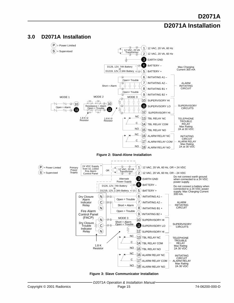
Figure 2: Stand-Alone Installation
= Power Limited
= Supervised
1
2
3
4
5
6
7
8
11
18
17
16
15
14
13
10
9
12 VAC, 20 VA, 60 Hz, OR + 24 VDC
ALARM RELAY NO
ALARM RELAY COM
ALARM RELAY NC
TBL RELAY NO
TBL RELAY COM
TBL RELAY NC
SUPERVISORY LO
SUPERVISORY HI
INITIATING B2 +
INITIATING B1 +
INITIATING A2 –
INITIATING A1 –
BATTERY +
BATTERY –
EARTH GND
12 VAC, 20 VA, 60 Hz, OR – 24 VDC
C
NC
NO
C
NC
NO
12 VAC, 20 VATransformer
MODE 3
24 VDC Supplyfrom UL Listed
Fire AlarmControl Panel
D126, 12V, 7Ah Batteryor
D1219, 12V, 2.3Ah Battery
-
+
OR
N
C
N
N
C
N
Fire AlarmControl Panel
(FACP)
Dry ClosureAlarm
IndicatorRelay
Dry ClosureTroubleIndicator
Relay
PrimaryPowerSupply
PS
PS
P S
P
P
P S
-
+
P S
Open = Trouble
Open = Trouble
AlternatePower Supply
Short = Alarm
Do not connect a battery whenconnected to a 24 VDC powersupply. Max Charging Current300 mA.
ALARMINITIATINGCIRCUIT
SUPERVISORYCIRCUITS
TELEPHONETROUBLE
RELAYMax Rating2A 30 VDC
INITIATINGCIRCUIT
ALARM RELAYMax Rating2A 30 VDC
12 SUPERVISORY HI
P S
Open = TroubleShort = Alarm
Do not connect earth groundwhen connected to a 24 VDCpower supply.
1.8 KResistor
Figure 3: Slave Communicator Installation
D2071A Installation
D2071A
D2071AOperation & Installation Manual74-06200-000-D Page 16 Copyright © 2001 Radionics
3.1 Before You BeginFollow the instructions in the sub-sections below to install the D2071A. Be aware that some terminals are wired differentlyfor the stand-alone (Figure 2) and slave (Figure 3) applications.
If you are using the D2071AC kit, mount the D4103R enclosure and have a qualified electrician connect a 110/120 VAC power source to the black and white leads on the transformer. Be certain the power source is turnedoff before you begin the installation of the D2071A.
3.2 Earth Ground WiringNote: Use Terminal 3 for earth ground connections.
3.2.1 12 VAC Mode
To help prevent damage from electrostatic charges or other transient electrical surges, connect the D2071A panel toearth ground at Terminal 3 before making any other connections to the panel. A grounding rod or cold water pipe arerecommended earth ground references. Do not use telephone or electrical ground for the earth ground connection. Use#16 AWG (1.5 mm) wire when making the connection. Do not connect any other terminals to earth ground.
3.2.2 24 VDC Mode
When the D2071A is connected to the 24 VDC output of an FACP, do not connect Terminal 3 to earth ground. Doing somay cause a continuous ground fault condition on the FACP.
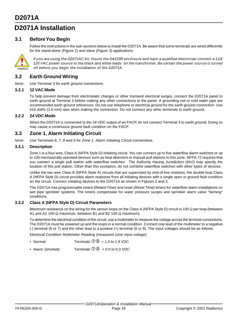
3.3 Zone 1, Alarm Initiating CircuitNote: Use Terminals 6, 7, 8 and 9 for Zone 1, Alarm Initiating Circuit connections.
3.3.1 Description
Zone 1 is a four-wire, Class A (NFPA Style D) initiating circuit. You can connect up to five waterflow alarm switches or upto 100 mechanically operated devices such as heat detectors or manual pull stations to this zone. NFPA 72 requires thatyou connect a single pull station with waterflow switches. The Authority Having Jurisdiction (AHJ) may specify thelocation of this pull station. Other than this exception, do not combine waterflow switches with other types of devices.
Unlike the two wire Class B (NFPA Style A) circuits that are supervised by end-of-line resistors, the double loop ClassA (NFPA Style D) circuit provides alarm response from all initiating devices with a single open or ground fault conditionon the circuit. Connect initiating devices to the D2071A as shown in Figures 2 and 3.
The D2071A has programmable retard (Retard Time) and reset (Reset Time) timers for waterflow alarm installations onwet pipe sprinkler systems. The timers compensate for water pressure surges and sprinkler alarm valve “fanning”conditions.
3.3.2 Class A (NFPA Style D) Circuit Parameters
Maximum resistance on the wiring for the sensor loops on the Class A (NFPA Style D) circuit is 100 Ω per loop (betweenA1 and A2 100 Ω maximum, between B1 and B2 100 Ω maximum).
To determine the electrical condition of the circuit, use a multimeter to measure the voltage across the terminal connections.The D2071A must be powered up and the loops in a normal condition. Connect one lead of the multimeter to a negative(-) terminal (6 or 7) and the other lead to a positive (+) terminal (8 or 9). The input voltages should be as follows:
Electrical Condition Multimeter Reading (measured zone input voltage)
• Normal: Terminals = 1.0 to 1.9 VDC
• Alarm (shorted): Terminals = 0.0 to 0.3 VDC
D2071A Installation
D2071A
D2071A Operation & Installation ManualCopyright © 2001 Radionics Page 17 74-06200-000-D
3.3.3 Retard and Reset Times
Only use the Zone 1 retard/reset feature for waterflow switches and/or controls without a retard/reset feature of theirown.
The retard timer prevents false alarms from conditions such as water supply surges in wet pipe sprinkler systems.Surges may result in the brief activation of a waterflow alarm switch. The value you enter in the program item RetardTime determines the length of time that the waterflow switch must remain activated before an alarm report is initiated.Generally, a 15 second retard is adequate, but a longer interval may be necessary when extended surge conditionsexist.
Reset Time is an additional program parameter that compensates for sprinkler alarm valve “fanning” conditions in wetpipe systems with unique hydraulic problems. Fanning occurs when a sprinkler head operates, or the inspector’s testvalve is opened, and the waterflow switch does not remain activated long enough to overcome the retard time, butcycles between alarm and normal conditions.
The retard timer (Retard Time) and the reset timer (Reset Time) work together as follows:
• The retard timer (Retard Time) keeps track of the amount of time which the Alarm Initiating Circuit is in the alarmcondition. It begins counting when the circuit enters the alarm condition.
• The reset timer (Reset Time) determines when the retard timer is reset to zero. When the Alarm Initiating Circuitenters a non-alarm (restored or trouble) condition, after being in the alarm condition, the retard timer stops at itscurrent value and the reset timer starts counting.
• If another alarm condition is detected before the reset timer reaches the value you entered in Reset Time, the retardtimer resumes counting from where it left off, and the reset timer is set to zero.
• If the amount of time specified in the Retard Time program item accumulates in one or more successive alarmactivations, the D2071A transmits an Alarm Zone 1 report and activates the alarm relay.
• The retard timer resets to zero only when the circuit remains in a non-alarm condition (restored or trouble) for theamount of time entered in Reset Time.
• When the Alarm Initiating Circuit has been normal for the time in Reset Time, the D2071A sends a Restoral Zone 1report.
Reset Time is typically set at half the Retard Time. If Retard Time were set at 15 seconds, Reset Time would be set at7 or 8 seconds.
3.3.4 Wiring
3.3.4.1 Stand-Alone Applications
Connect the normally-open contacts of each waterflow switch (maximum of 5) or mechanically activated initiatingdevice to the Alarm Initiating Circuit in parallel as shown in Figure 2.
3.3.4.2 Slave Communicator Applications
1) Connect the Alarm Initiating Circuit to an alarm indicator output (normally-open, dry closure) on the FACP (seeFigure 3).
2) Connect Terminals 6 and 7 to the common contact, and Terminals 8 and 9 to the normally-open contact.
3) Program Retard Time and Reset Time for 0 seconds when connecting the Alarm Initiating Circuit to an existingFACP.
D2071A Installation
D2071A
D2071AOperation & Installation Manual74-06200-000-D Page 18 Copyright © 2001 Radionics
3.4 Zones 2 and 3, Supervisory CircuitsNote: Use Terminals 10, 11 and 12 for supervisory circuit connections.
3.4.1 Description
Zones 2 and 3 are Class B (NFPA Style A) circuits that can monitor sprinkler supervision devices such as valve tampers(maximum of 20 per circuit) in stand-alone applications. In slave communicator applications these circuits monitor thetrouble outputs of an associated FACP.
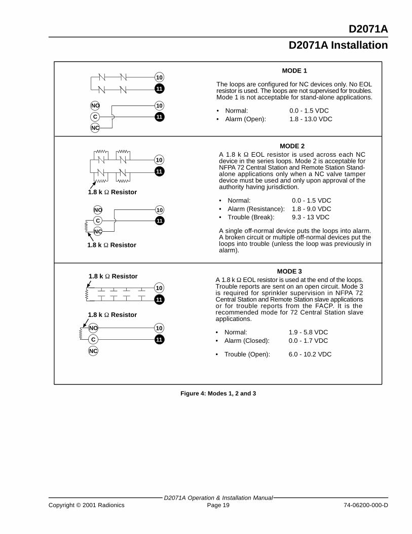
You can wire the Class B (NFPA Style A) circuits in three different ways: Mode 1, 2, or 3. Program item Class B Modedetermines the mode for both Zones 2 and 3. Wire both circuits for the same mode configuration. Connect dry contactdevices to the Supervisory Circuits in series (normally-closed), or in parallel (normally-open). Install a 1.8 k Ω resistorat the end of the Class B (NFPA Style A) circuits if needed (see Figure 4).
Mode 1 has only two status conditions: Alarm and Normal. Modes 2 and 3 have three status conditions: Alarm, Trouble,and Normal. The D2071A transmits an alarm report for a trouble condition when you use a Mode 1 or Mode 2 circuit tomonitor an FACP trouble output or sprinkler valve tamper.
3.4.1.1 Mode 1 and Mode 2 Restrictions
You cannot use Mode 1 for sprinkler supervision (stand-alone) in NFPA 72 Remote Station installations. Mode 3 isrecommended. Only use Mode 2 when a normally closed contact valve tamper device must be used, and only uponapproval of the authority having jurisdiction. For more information concerning Modes and NFPA requirements, refer tothe Listings and Approvals section in the front of this manual.
3.4.2 Wiring
3.4.2.1 Stand-alone Applications
• Connect supervision devices (maximum of 20 per circuit) such as valve tamper switches to Terminals 10 and 11(Zone 2) or 11 and 12 (Zone 3) as shown in Figure 4.
• Program item Class B Mode for the wiring configuration you use.
• There should be no more than 100 Ω resistance on the sensor loops for the Class B (NFPA Style A) circuits.
3.4.2.2 Slave Communicator Applications
• When connecting the D2071A to an FACP, use the Mode 3 configuration for slave communicator applications (seeFigure 4).
• Connect Terminals 10 and 11 (Zone 2) or 11 and 12 (Zone 3) to the trouble outputs (dry closure) on the FACP.
• Connect Terminal 10 or 12 to the normally-open contact, and Terminal 11 to the common contact.
• Install a 1.8 k Ω resistor between the normally open and normally closed contacts.
• You must program Class B Mode for Mode 3.
3.4.3 Class B (NFPA Style A) Circuit Parameters
To determine the electrical condition of the Class B (NFPA Style A) Supervisory Circuits, use a voltmeter to measure thevoltage across the terminal connections (refer to Figure 4 for loop voltages). The loop must be connected, and theD2071A must be powered.
D2071A Installation
D2071A
D2071A Operation & Installation ManualCopyright © 2001 Radionics Page 19 74-06200-000-D
MODE 3A 1.8 k Ω EOL resistor is used at the end of the loops.Trouble reports are sent on an open circuit. Mode 3is required for sprinkler supervision in NFPA 72Central Station and Remote Station slave applicationsor for trouble reports from the FACP. It is therecommended mode for 72 Central Station slaveapplications.
• Normal: 1.9 - 5.8 VDC• Alarm (Closed): 0.0 - 1.7 VDC
• Trouble (Open): 6.0 - 10.2 VDC
10
11
10
11
10
11
10
11
NC
C
NO
10
11
NC
C
NO
10
11
NC
C
NO
1.8 k Ω Resistor
1.8 k Ω Resistor
1.8 k Ω Resistor
1.8 k Ω Resistor
MODE 1
The loops are configured for NC devices only. No EOLresistor is used. The loops are not supervised for troubles.Mode 1 is not acceptable for stand-alone applications.
• Normal: 0.0 - 1.5 VDC• Alarm (Open): 1.8 - 13.0 VDC
MODE 2A 1.8 k Ω EOL resistor is used across each NCdevice in the series loops. Mode 2 is acceptable forNFPA 72 Central Station and Remote Station Stand-alone applications only when a NC valve tamperdevice must be used and only upon approval of theauthority having jurisdiction.
• Normal: 0.0 - 1.5 VDC• Alarm (Resistance): 1.8 - 9.0 VDC• Trouble (Break): 9.3 - 13 VDC
A single off-normal device puts the loops into alarm.A broken circuit or multiple off-normal devices put theloops into trouble (unless the loop was previously inalarm).
Figure 4: Modes 1, 2 and 3
D2071A Installation
D2071A
D2071AOperation & Installation Manual74-06200-000-D Page 20 Copyright © 2001 Radionics
3.5 Initiating Circuit Alarm RelayNote: Use Terminals 16, 17 and 18 for initiating circuit alarm relay connections.
3.5.1 Description
Install a D136 Relay in Socket K6 to use the optional Initiating Circuit Alarm relay. The D136 provides a Form “C” drycontact, rated at 2 A maximum current at 30 VDC (power from independent supply). The relay activates (reverse state)when the Class A (NFPA Style D) Alarm Initiating Circuit (Zone 1) goes into an alarm condition. It deactivates when thecircuit restores to normal.
• Terminal 17 is the relay common
• Terminal 16 is normally-closed
• Terminal 18 is normally-open
In a normal state, Terminals 16 and 17 have continuity. When activated, Terminals 17 and 18 have continuity.
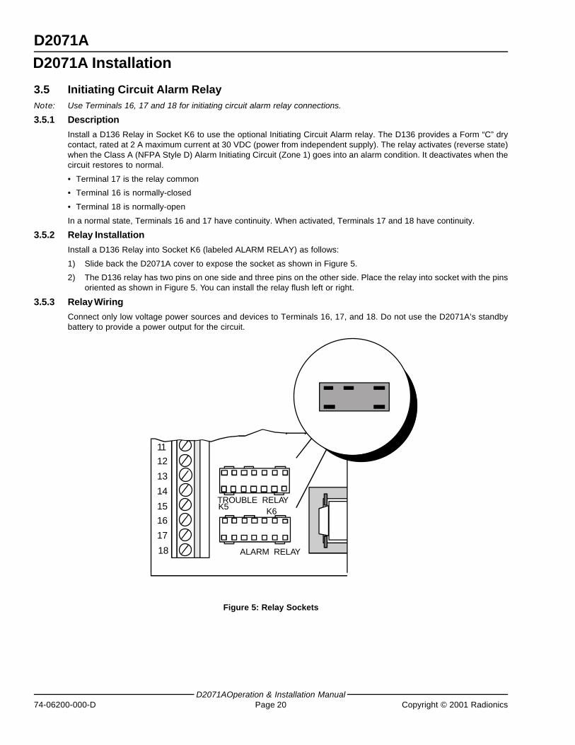
3.5.2 Relay Installation
Install a D136 Relay into Socket K6 (labeled ALARM RELAY) as follows:
1) Slide back the D2071A cover to expose the socket as shown in Figure 5.
2) The D136 relay has two pins on one side and three pins on the other side. Place the relay into socket with the pinsoriented as shown in Figure 5. You can install the relay flush left or right.
3.5.3 Relay Wiring
Connect only low voltage power sources and devices to Terminals 16, 17, and 18. Do not use the D2071A’s standbybattery to provide a power output for the circuit.
K6
ALARM RELAY
K5
18
17
16
15
14
13
12
11
10
TROUBLE RELAY
Figure 5: Relay Sockets
D2071A Installation
D2071A
D2071A Operation & Installation ManualCopyright © 2001 Radionics Page 21 74-06200-000-D
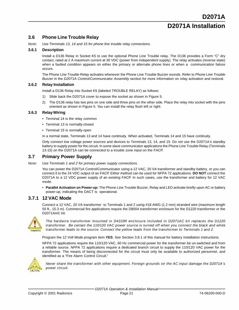
3.6 Phone Line Trouble RelayNote: Use Terminals 13, 14 and 15 for phone line trouble relay connections.
3.6.1 Description
Install a D136 Relay in Socket K5 to use the optional Phone Line Trouble relay. The D136 provides a Form “C” drycontact, rated at 2 A maximum current at 30 VDC (power from independent supply). The relay activates (reverse state)when a faulted condition appears on either the primary or alternate phone lines or when a communication failureoccurs.
The Phone Line Trouble Relay activates whenever the Phone Line Trouble Buzzer sounds. Refer to Phone Line TroubleBuzzer in the D2071A Control/Communicator Assembly section for more information on relay activation and restoral.
3.6.2 Relay Installation
Install a D136 Relay into Socket K5 (labeled TROUBLE RELAY) as follows:
1) Slide back the D2071A cover to expose the socket as shown in Figure 5.
2) The D136 relay has two pins on one side and three pins on the other side. Place the relay into socket with the pinsoriented as shown in Figure 5. You can install the relay flush left or right.
3.6.3 Relay Wiring
• Terminal 14 is the relay common
• Terminal 13 is normally-closed
• Terminal 15 is normally-open
In a normal state, Terminals 13 and 14 have continuity. When activated, Terminals 14 and 15 have continuity.
Only connect low voltage power sources and devices to Terminals 13, 14, and 15. Do not use the D2071A’s standbybattery to supply power for the circuit. In some slave communicator applications the Phone Line Trouble Relay (Terminals13-15) on the D2071A can be connected to a trouble zone input on the FACP.
3.7 Primary Power SupplyNote: Use Terminals 1 and 2 for primary power supply connections.
You can power the D2071A Control/Communicator using a 12 VAC, 20 VA transformer and standby battery, or you canconnect it to the 24 VDC output of an FACP. Either method can be used for NFPA 72 applications. DO NOT connect theD2071A to a 12 VDC power supply of an existing FACP. In such cases, use the transformer and battery for 12 VACmode.
• Parallel Activation on Power-up: The Phone Line Trouble Buzzer, Relay and LED activate briefly upon AC or batterypower-up, indicating the DACT is operational.
3.7.1 12 VAC ModeConnect a 12 VAC, 20 VA transformer to Terminals 1 and 2 using #18 AWG (1.2 mm) stranded wire (maximum length50 ft., 15.3 m). Commercial fire applications require the D8004 transformer enclosure for the D1220 transformer or theD2071AmC kit.
The hardwire transformer mounted in D4103R enclosure included in D2071AC kit replaces the D1220transformer. Be certain the 110/120 VAC power source is turned off when you connect the black and whitetransformer leads to the source. Connect the yellow leads from the transformer to Terminals 1 and 2.
Program the 12 Volt Mode program item YES. See Section 3.8.1 of this manual for battery installation instructions.
NFPA 72 applications require the 110/120 VAC, 60 Hz commercial power for the transformer be un-switched and froma reliable source. NFPA 72 applications require a dedicated branch circuit to supply the 110/120 VAC power for thetransformer. The means of being disconnected for the circuit must only be available to authorized personnel, andidentified as a “Fire Alarm Control Circuit.”
Never share the transformer with other equipment. Foreign grounds on the AC input damage the D2071A’spower circuit.
D2071A Installation
D2071A
D2071AOperation & Installation Manual74-06200-000-D Page 22 Copyright © 2001 Radionics
3.7.2 24 VDC Mode
Connect a 24 VDC, uninterrupted, regulated, auxiliary output from an FACP to Terminals 1 and 2. Set program item 12Volt Mode to NO. Terminals 1 (+) and 2 (-) are polarity protected when the D2071A is programmed for the 24 VDC mode.
Do not connect a 12 VDC standby battery and do not connect earth ground to the D2071A when it is in 24 VDC mode.
The discharge/recharge schedule below shows the voltages at Terminals 1 and 2 that generate battery reports with theD2071A in 24 VDC mode. If the voltage falls below 11.1 VDC, the D2071A is not operational.
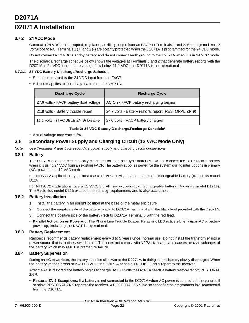
3.7.2.1 24 VDC Battery Discharge/Recharge Schedule
• Source supervised is the 24 VDC input from the FACP.
• Schedule applies to Terminals 1 and 2 on the D2071A.
Discharge Cycle Recharge Cycle
27.6 volts - FACP battery float voltage AC On - FACP battery recharging begins
21.8 volts - Battery trouble report 24.7 volts - Battery restoral report (RESTORAL ZN 9)
11.1 volts - (TROUBLE ZN 9) Disable 27.6 volts - FACP battery charged
Table 2: 24 VDC Battery Discharge/Recharge Schedule*
* Actual voltage may vary ± 5%
3.8 Secondary Power Supply and Charging Circuit (12 VAC Mode Only)Note: Use Terminals 4 and 5 for secondary power supply and charging circuit connections.
3.8.1 Battery
The D2071A charging circuit is only calibrated for lead-acid type batteries. Do not connect the D2071A to a batterywhen it is using 24 VDC from an existing FACP. The battery supplies power for the system during interruptions in primary(AC) power in the 12 VAC mode.
For NFPA 72 applications, you must use a 12 VDC, 7 Ah, sealed, lead-acid, rechargeable battery (Radionics modelD126).
For NFPA 72 applications, use a 12 VDC, 2.3 Ah, sealed, lead-acid, rechargeable battery (Radionics model D1219).The Radionics model D126 exceeds the standby requirements and is also acceptable.
3.8.2 Battery Installation
1) Install the battery in an upright position at the base of the metal enclosure.
2) Connect the negative side of the battery (black) to D2071A Terminal 4 with the black lead provided with the D2071A.
3) Connect the positive side of the battery (red) to D2071A Terminal 5 with the red lead.
• Parallel Activation on Power-up: The Phone Line Trouble Buzzer, Relay and LED activate briefly upon AC or batterypower-up, indicating the DACT is operational.
3.8.3 Battery Replacement
Radionics recommends battery replacement every 3 to 5 years under normal use. Do not install the transformer into apower source that is routinely switched off. This does not comply with NFPA standards and causes heavy discharges ofthe battery which may result in premature failure.
3.8.4 Battery Supervision
During an AC power loss, the battery supplies all power to the D2071A. In doing so, the battery slowly discharges. Whenthe battery voltage drops below 11.8 VDC, the D2071A sends a TROUBLE ZN 9 report to the receiver.
After the AC is restored, the battery begins to charge. At 13.4 volts the D2071A sends a battery restoral report, RESTORALZN 9.
• Restoral ZN 9 Exceptions: If a battery is not connected to the D2071A when AC power is connected, the panel stillsends a RESTORAL ZN 9 report to the receiver. A RESTORAL ZN 9 is also sent after the programmer is disconnectedfrom the D2071A.
D2071A Installation
D2071A
D2071A Operation & Installation ManualCopyright © 2001 Radionics Page 23 74-06200-000-D
3.8.5 Battery Charging Circuit
The D2071A charges the battery with a float charge circuit. Maximum charging current is 300 mA. The Battery Discharge/Recharge Schedule shows voltages during the discharge/recharge cycle.
3.8.5.1 12 VAC Battery Discharge/Recharge Schedule
• Source supervised is the battery connected to the D2071A.
Discharge Cycle Recharge Cycle
13.8 volts - FACP battery float voltage AC On - Battery recharging begins
11.8 volts - Battery trouble report (TROUBLE ZN 9)9.0 volts - Battery trouble report (only if batterydischarged below 8.5 volts)
8.5 volts - Disable all processing and memoryfunctions (deep battery discharge can occur belowthis level)
13.4 volts - Battery restoral report (RESTORAL ZN 9)
13.8 volts - Battery charged
Table 3: 12 VAC Battery Discharge/Recharge Schedule*
* Actual voltage may vary by as much as ± 5%.
3.9 Telephone Connections3.9.1 Telephone Cord Installation
Connect the primary phone line to the D2071A modular Jack “J1” using a D161 or D162 Phone Cord. Connect thealternate phone line to the D2071A modular Jack “J2” using another D161 or D162 Phone Cord.
You must connect separate primary and alternate phone lines to the D2071A for all applications.
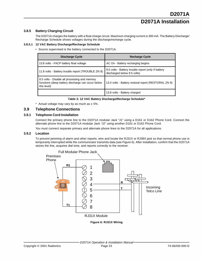
3.9.2 Location
To prevent jamming of alarm and other reports, wire and locate the RJ31X or RJ38X jack so that normal phone use istemporarily interrupted while the communicator transmits data (see Figure 6). After installation, confirm that the D2071Aseizes the line, acquires dial tone, and reports correctly to the receiver.
R1
T1
12345678
R
T IncomingTelco Line
RJ31X Module
PremisesPhone
Full Modular Phone Jack
Figure 6: RJ31X Wiring
D2071A Installation
D2071A
D2071AOperation & Installation Manual74-06200-000-D Page 24 Copyright © 2001 Radionics
3.9.3 Telephone Line Supervision
The D2071A monitors both the Primary and Alternate telephone lines while the communicator is idle by “sniffing” theline for trouble. Phone line trouble is defined as line voltage below 10 VDC and current less than 10 mA. Total time fortrouble indication is 210-240 seconds. If there is a report to transmit, the D2071A does not “sniff” the phone lines untilthe report is transmitted or a communication failure occurs. The D2071A reports a faulted condition on the Primaryphone line as a TROUBLE ZN B and the Alternate phone line as a TROUBLE ZONE C.
Each line is “sniffed” once a minute if both lines are good. If a line is determined to be in trouble, the D2071A steps upthe test rate and “sniffs” once every ten seconds. If the trouble still exists after 15 samples (150 seconds), the panelsends a trouble report and activates the buzzer, Phone Fail LED, and Phone Line Trouble Relay (if installed). SeeSection 3.6 of this manual for telephone trouble relay for installation instructions.
The buzzer, LED, and relay are deactivated after a trouble condition on the phone line when the receiver acknowledgesthe phone line trouble report, or when the line returns to normal. If the D2071A attempts to transmit the phone linetrouble report ten times without acknowledgment from the receiver, communication failure occurs.
If the D2071A is in communication failure, either the primary and alternate phone lines must be detected as normal anda report acknowledged by the receiver before the buzzer, LED, and relay are deactivated. Refer to the troubleshootingsection of this manual for help in finding the cause of phone line problems.
The buzzer, light, and relay may remain activated for up to 24 hours if the communications failure was not due to troubleconditions detected on the phone lines, and no other report is transmitted before the next scheduled test report.
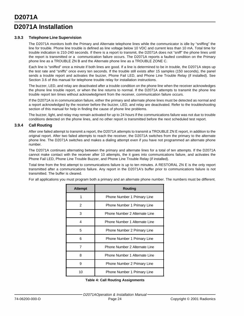
3.9.4 Call Routing
After one failed attempt to transmit a report, the D2071A attempts to transmit a TROUBLE ZN E report, in addition to theoriginal report. After two failed attempts to reach the receiver, the D2071A switches from the primary to the alternatephone line. The D2071A switches and makes a dialing attempt even if you have not programmed an alternate phonenumber.
The D2071A continues alternating between the primary and alternate lines for a total of ten attempts. If the D2071Acannot make contact with the receiver after 10 attempts, the it goes into communications failure, and activates thePhone Fail LED, Phone Line Trouble Buzzer, and Phone Line Trouble Relay (if installed).
Total time from the first attempt to communications failure is up to ten minutes. A RESTORAL ZN E is the only reporttransmitted after a communications failure. Any report in the D2071A's buffer prior to communications failure is nottransmitted. The buffer is cleared.
For all applications you must program both a primary and an alternate phone number. The numbers must be different.
Attempt Routing
1 Phone Number 1 Primary Line
2 Phone Number 1 Primary Line
3 Phone Number 2 Alternate Line
4 Phone Number 1 Alternate Line
5 Phone Number 2 Primary Line
6 Phone Number 1 Primary Line
7 Phone Number 2 Alternate Line
8 Phone Number 1 Alternate Line
9 Phone Number 2 Primary Line
10 Phone Number 1 Primary Line
Table 4: Call Routing Assignments
D2071A Installation
D2071A
D2071A Operation & Installation ManualCopyright © 2001 Radionics Page 25 74-06200-000-D
3.9.5 Notification
Do NOT connect registered equipment to party lines or coin operated telephones. If the local telephone companyrequests notification before you connect the D2071A to the telephone network, supply the following information:
• the particular line you are connecting the panel to,
• the make, model, and serial number of the device, and
• the FCC registration number (AJ9USA-61104-AL-E) and ringer equivalence (0.0B = AC, 1.3B = DC).
If the telephone company makes changes in its communications facilities, equipment, operations, or procedures thatmay affect the performance of the communicator, the phone company is obligated to notify the user in writing.
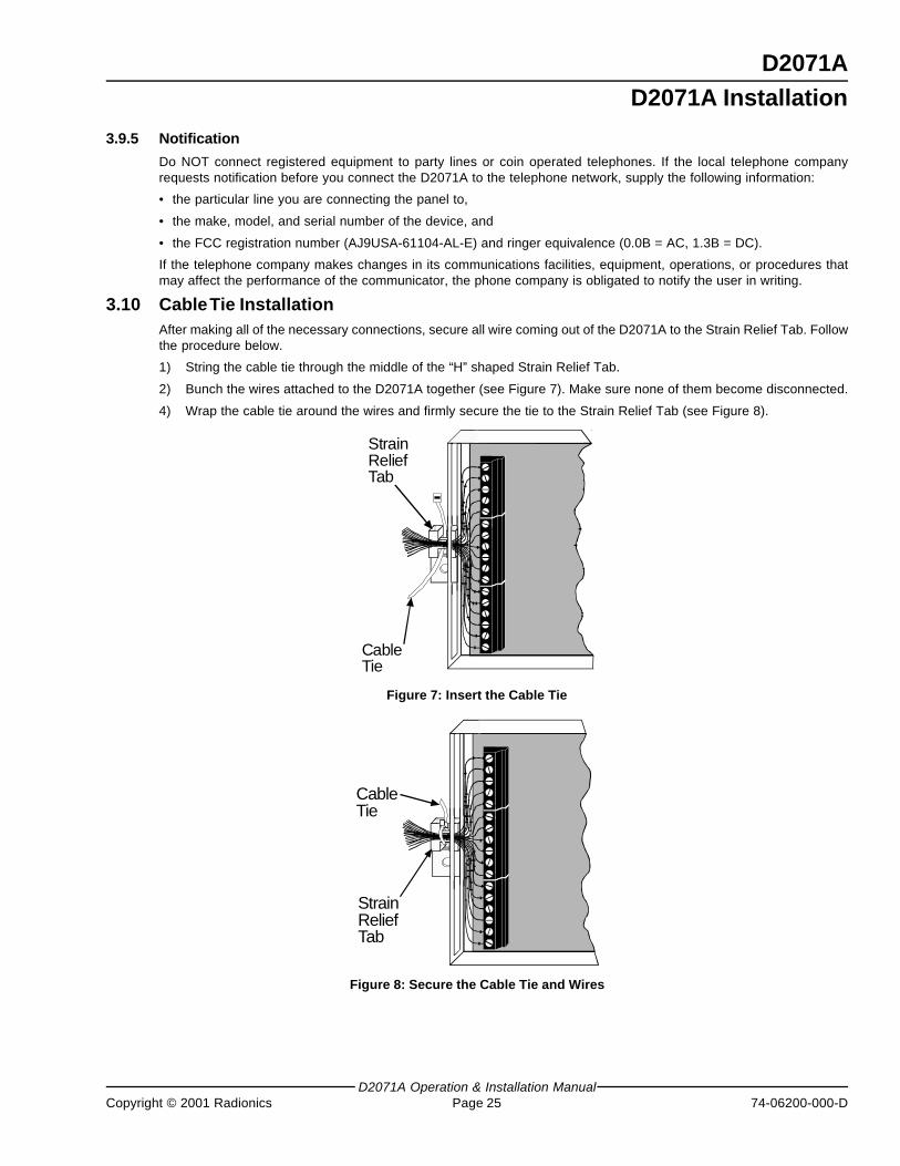
3.10 Cable Tie InstallationAfter making all of the necessary connections, secure all wire coming out of the D2071A to the Strain Relief Tab. Followthe procedure below.
1) String the cable tie through the middle of the “H” shaped Strain Relief Tab.
2) Bunch the wires attached to the D2071A together (see Figure 7). Make sure none of them become disconnected.
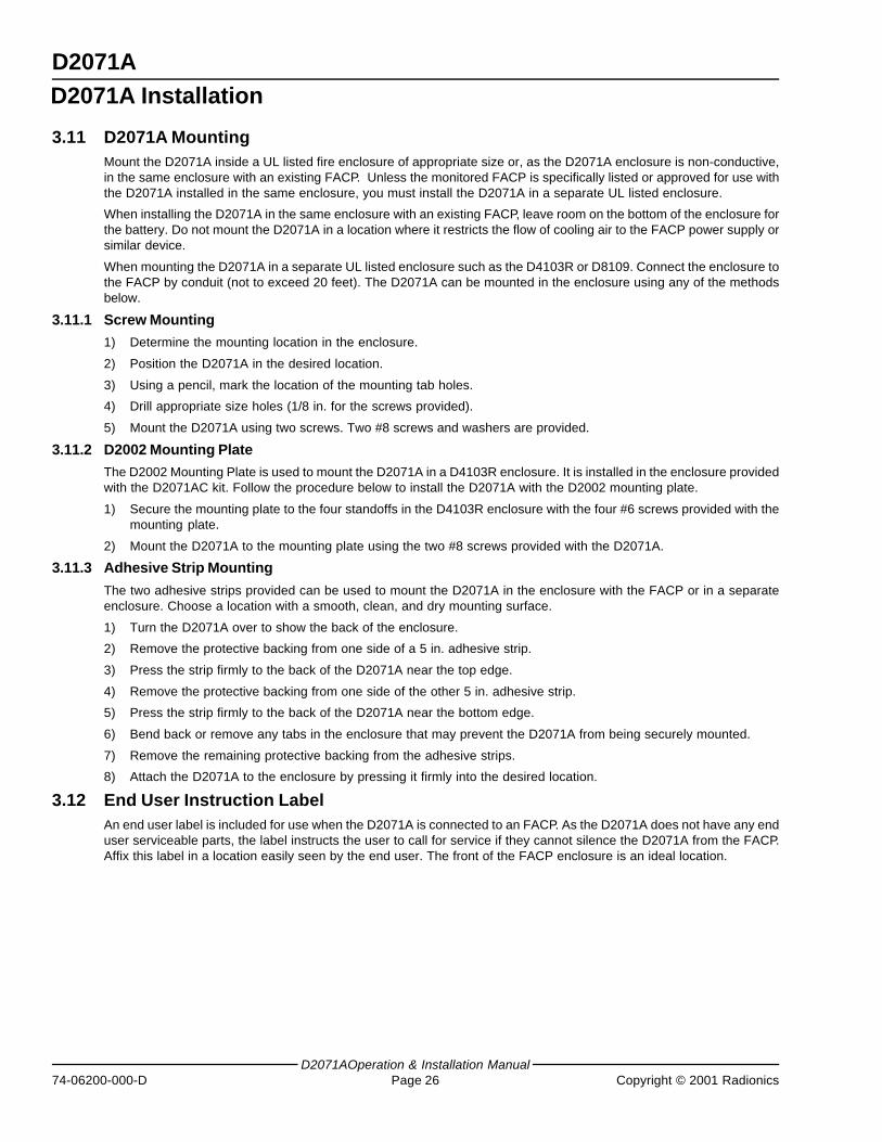
4) Wrap the cable tie around the wires and firmly secure the tie to the Strain Relief Tab (see Figure 8).
StrainReliefTab
CableTie
Figure 7: Insert the Cable Tie
StrainReliefTab
CableTie
Figure 8: Secure the Cable Tie and Wires
D2071A Installation
D2071A
D2071AOperation & Installation Manual74-06200-000-D Page 26 Copyright © 2001 Radionics
3.11 D2071A MountingMount the D2071A inside a UL listed fire enclosure of appropriate size or, as the D2071A enclosure is non-conductive,in the same enclosure with an existing FACP. Unless the monitored FACP is specifically listed or approved for use withthe D2071A installed in the same enclosure, you must install the D2071A in a separate UL listed enclosure.
When installing the D2071A in the same enclosure with an existing FACP, leave room on the bottom of the enclosure forthe battery. Do not mount the D2071A in a location where it restricts the flow of cooling air to the FACP power supply orsimilar device.
When mounting the D2071A in a separate UL listed enclosure such as the D4103R or D8109. Connect the enclosure tothe FACP by conduit (not to exceed 20 feet). The D2071A can be mounted in the enclosure using any of the methodsbelow.
3.11.1 Screw Mounting
1) Determine the mounting location in the enclosure.
2) Position the D2071A in the desired location.
3) Using a pencil, mark the location of the mounting tab holes.
4) Drill appropriate size holes (1/8 in. for the screws provided).
5) Mount the D2071A using two screws. Two #8 screws and washers are provided.
3.11.2 D2002 Mounting Plate
The D2002 Mounting Plate is used to mount the D2071A in a D4103R enclosure. It is installed in the enclosure providedwith the D2071AC kit. Follow the procedure below to install the D2071A with the D2002 mounting plate.
1) Secure the mounting plate to the four standoffs in the D4103R enclosure with the four #6 screws provided with themounting plate.
2) Mount the D2071A to the mounting plate using the two #8 screws provided with the D2071A.
3.11.3 Adhesive Strip Mounting
The two adhesive strips provided can be used to mount the D2071A in the enclosure with the FACP or in a separateenclosure. Choose a location with a smooth, clean, and dry mounting surface.
1) Turn the D2071A over to show the back of the enclosure.
2) Remove the protective backing from one side of a 5 in. adhesive strip.
3) Press the strip firmly to the back of the D2071A near the top edge.
4) Remove the protective backing from one side of the other 5 in. adhesive strip.
5) Press the strip firmly to the back of the D2071A near the bottom edge.
6) Bend back or remove any tabs in the enclosure that may prevent the D2071A from being securely mounted.
7) Remove the remaining protective backing from the adhesive strips.
8) Attach the D2071A to the enclosure by pressing it firmly into the desired location.
3.12 End User Instruction LabelAn end user label is included for use when the D2071A is connected to an FACP. As the D2071A does not have any enduser serviceable parts, the label instructs the user to call for service if they cannot silence the D2071A from the FACP.Affix this label in a location easily seen by the end user. The front of the FACP enclosure is an ideal location.
D2071A Installation
D2071A
D2071A Operation & Installation ManualCopyright © 2001 Radionics Page 27 74-06200-000-D
4.0 D2071A Programming4.1 Description
This section provides a brief operation overview of the D5200 Programmer. It is not intended to be a substitute for theD5200 Operation Manual (74-06176-000). You should be familiar with the D5200 Operation Manual before attempting toprogram any Radionics Product.
To program the D2071A DACT with the D5200 Programmer, make sure the programmer contains the 2071 ProductHandler Program. See the D5200 Programmer Operation Manual for D5200 update instructions.
4.2 Navigating Through Handlers and Program RecordsAccess program items by navigating through “groups” of the programmer. Use the red ENTER GROUP and EXITGROUP keys to move in and out of each group (see Figure 9).
Use the red up ↑ and down ↓ arrow keys to scroll through the list of items at each group. Scroll through a list of availableproduct handlers at the Product Handler Group. See saved record titles at the Record Group, and program items are atthe Program Item group.
Use the red left ← and right → arrow keys to move the cursor horizontally within one line of the LCD display.
Figure 9 shows an example of how to use navigational keys to move through the 2071 program. Use these keys thesame way for all product handlers.
4.3 Function KeysSix function keys simplify the use of the programmer.
• ON: The red ON key switches the programmer on. This key does not power down the programmer. Switch the D5200off by selecting 5200 OFF in the PRODUCT HANDLERS menu, or it will power down automatically after the programmedTime Out time has elapsed.
• HELP: The red HELP key switches the programmer into help mode. See the D5200 Operation and Installation Manualfor more information.
• CANCEL: Use the red CANCEL key to undo changed items if you have not yet accepted the change by pressing thewhite ENTER key.
• CLEAR: The red CLEAR key erases unENTERed or ENTERED program item data, and replaces it with blank spaces.
• RECV (COPY): The red RECV (COPY) key moves a copy of the record in the attached product to the D5200Programmer.
• SEND (LOAD): The red SEND (LOAD) key moves a copy of the record in the D5200 Programmer to a product you areprogramming.
4.4 Data KeysThe white keys on the keyboard are used for data entry.
D2071A Programming
D2071A
D2071AOperation & Installation Manual74-06200-000-D Page 28 Copyright © 2001 Radionics
4.5 Helpful TonesThe D5200 Programmer emits four distinct sounds, which notify the user of key presses, data acceptance/rejection, andsystem errors.
• Click: A short, sharp click occurs every time you press a key. The programmer does not click when you press the ON,CAP LOCK, and SHIFT keys.
• Pip: A short, single frequency tone sounds when you press the white ENTER key and the D5200 accepts thechange.
• Tweedle: A quick series of pips indicating that you pressed an invalid key or made an inappropriate entry.
• Buzz: A sour, flat tone indicates a system error. Examples of typical system errors follow:
• A product is not connected to D5200 when you try to copy or load it.
• The D5200 is notifying you of a low battery condition.
• The D5200 announces that it will automatically count down and then turn off.
• You are attempting to delete a record or handler.
• You are entering into a product handler which contains a TIMEOUTSAVE record. The TIMEOUTSAVE recordwas saved by the D5200 when the it automatically turned off to save power.
4.6 Editing a RecordTo make changes to an existing 2071 record:
1) Scroll to the 2071 product handler from the Product Handlers menu using the red ↓ or ↑ keys, and press the redENTER GROUP key.
2) Scroll to the appropriate record title using the red ↓ or ↑ keys, and press the red ENTER GROUP key.
3) Scroll to the appropriate program item using the red ↓ or ↑ keys, and edit the entry. Press the white ENTER key toenter the new data.
4) Press the red EXIT GROUP key to exit from the record. The SAVE display appears if changes have been made toany program item entries in the record.
4.7 Programmer ConnectionTo access the four-pin Programmer Connector (J3), slide back the cover on the D2071A. The Programmer Connector isnext to Terminal 1 (see Figure 1). The D2071A is ready for programming after connecting it to the programmer. It is notnecessary to reset the D2071A before loading to, or copying from the panel.
• Programming before installing the phone lines may sound the buzzer: You can program the D2071A prior toinstallation. However, if the D2071A is powered and not connected to a phone line, the phone fail buzzer sounds afterapproximately ten minutes. Power down the unit to silence the buzzer.
Program the Radionics D2071A using the Radionics D5200 Programmer containing the 2071 Product Handler. Beforeprogramming the D2071A, it is recommended that you read and become familiar with this section of the manual.
4.8 Entering the 2071 Handler1) Starting at PRODUCT HANDLERS, press the red ↓ key until the cursor is on 2071. Press the red ENTER GROUP
key.
2) The cursor appears on the NEWRECORD prompt. Press the red ENTER GROUP key.
3) The D5200 displays Account #.
4.9 Program ModulesUnlike larger Radionics products, the 2071 Product Handler does not group Program Items in Program Modules. Youare in the Program Item Level as soon as you enter the 2071 program.
D2071A Programming
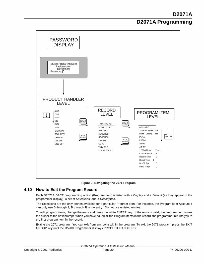
D2071A
D2071A Operation & Installation ManualCopyright © 2001 Radionics Page 29 74-06200-000-D
D2071A Programming
PASSWORDDISPLAY
D5200 PROGRAMMERRadionics Inc.
Rev [##.##]Password:
PRODUCT HANDLERLEVEL
4112
7112
6112
636
2071
8112
DISKSTAT
SECURITY
UPDATE
DELETE
5200 OFF
ENTERGROUP
EXITGROUP
EXITGROUP
ENTERGROUP2071 [##.##]
NEWRECORD
RECORD1
RECORD2
RECORD3
DELETE
COPY
VISMODE
LOCKRECORD
Account #
Transmit BFSK No
DTMF Dialing Yes
PriPre
PriPh#
AltPre
AltPh#
12 Volt Mode Yes
Class B Mode 3
Retard Time 0
Reset Time 0
Hrs Til Rpt 0
Mins Til Rpt 0
ENTER
RECORDLEVEL PROGRAM ITEM
LEVEL
Figure 9: Navigating the 2071 Program
4.10 How to Edit the Program RecordEach D2071A DACT programming option (Program Item) is listed with a Display and a Default (as they appear in theprogrammer display), a set of Selections, and a Description.
The Selections are the only entries available for a particular Program Item. For instance, the Program item Account #can only use 0 through 9, B through F, or no entry. Do not use unlisted entries.
To edit program items, change the entry and press the white ENTER key. If the entry is valid, the programmer movesthe cursor to the next prompt. When you have edited all the Program Items in the record, the programmer returns you tothe first program item in the record.
Exiting the 2071 program: You can exit from any point within the program. To exit the 2071 program, press the EXITGROUP key until the D5200 Programmer displays PRODUCT HANDLERS.
D2071A
D2071AOperation & Installation Manual74-06200-000-D Page 30 Copyright © 2001 Radionics
D2071A Programming
Notes:
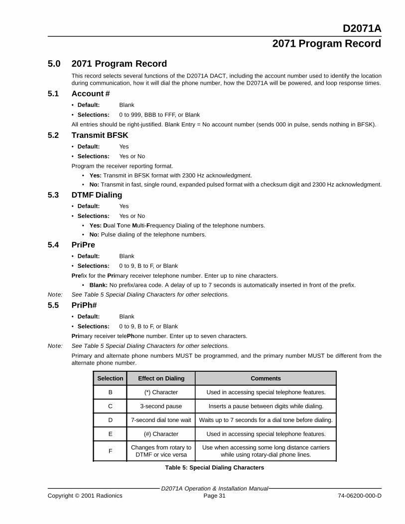
D2071A
D2071A Operation & Installation ManualCopyright © 2001 Radionics Page 31 74-06200-000-D
2071 Program Record
5.0 2071 Program RecordThis record selects several functions of the D2071A DACT, including the account number used to identify the locationduring communication, how it will dial the phone number, how the D2071A will be powered, and loop response times.
5.1 Account #• Default: Blank
• Selections: 0 to 999, BBB to FFF, or Blank
All entries should be right-justified. Blank Entry = No account number (sends 000 in pulse, sends nothing in BFSK).
5.2 Transmit BFSK• Default: Yes
• Selections: Yes or No
Program the receiver reporting format.
• Yes: Transmit in BFSK format with 2300 Hz acknowledgment.
• No: Transmit in fast, single round, expanded pulsed format with a checksum digit and 2300 Hz acknowledgment.
5.3 DTMF Dialing• Default: Yes
• Selections: Yes or No
• Yes: Dual Tone Multi-Frequency Dialing of the telephone numbers.
• No: Pulse dialing of the telephone numbers.
5.4 PriPre• Default: Blank
• Selections: 0 to 9, B to F, or Blank
Prefix for the Primary receiver telephone number. Enter up to nine characters.
• Blank: No prefix/area code. A delay of up to 7 seconds is automatically inserted in front of the prefix.
Note: See Table 5 Special Dialing Characters for other selections.
5.5 PriPh#• Default: Blank
• Selections: 0 to 9, B to F, or Blank
Primary receiver telePhone number. Enter up to seven characters.
Note: See Table 5 Special Dialing Characters for other selections.
Primary and alternate phone numbers MUST be programmed, and the primary number MUST be different from thealternate phone number.
Selection Effect on Dialing Comments
B (*) Character Used in accessing special telephone features.
C 3-second pause Inserts a pause between digits while dialing.
D 7-second dial tone wait Waits up to 7 seconds for a dial tone before dialing.
E (#) Character Used in accessing special telephone features.
FChanges from rotary to
DTMF or vice versaUse when accessing some long distance carriers
while using rotary-dial phone lines.
Table 5: Special Dialing Characters
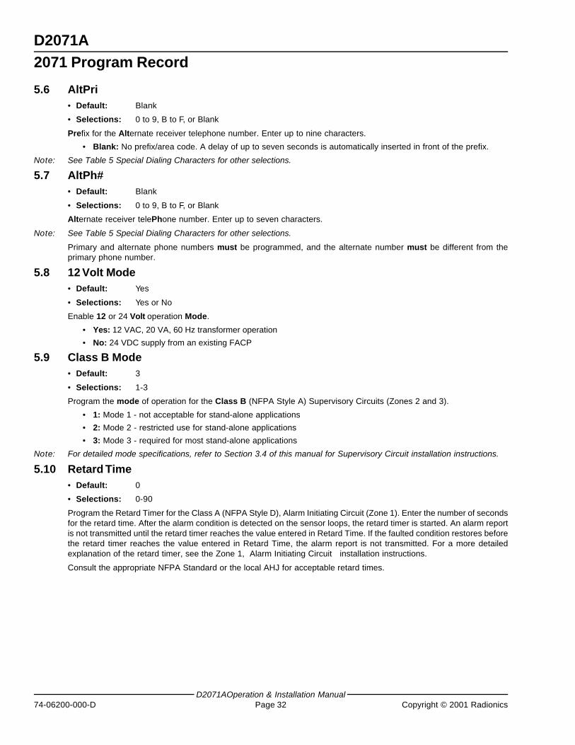
D2071A
D2071AOperation & Installation Manual74-06200-000-D Page 32 Copyright © 2001 Radionics
5.6 AltPri• Default: Blank
• Selections: 0 to 9, B to F, or Blank
Prefix for the Alternate receiver telephone number. Enter up to nine characters.
• Blank: No prefix/area code. A delay of up to seven seconds is automatically inserted in front of the prefix.
Note: See Table 5 Special Dialing Characters for other selections.
5.7 AltPh#• Default: Blank
• Selections: 0 to 9, B to F, or Blank
Alternate receiver telePhone number. Enter up to seven characters.
Note: See Table 5 Special Dialing Characters for other selections.
Primary and alternate phone numbers must be programmed, and the alternate number must be different from theprimary phone number.
5.8 12 Volt Mode• Default: Yes
• Selections: Yes or No
Enable 12 or 24 Volt operation Mode.
• Yes: 12 VAC, 20 VA, 60 Hz transformer operation
• No: 24 VDC supply from an existing FACP
5.9 Class B Mode• Default: 3
• Selections: 1-3
Program the mode of operation for the Class B (NFPA Style A) Supervisory Circuits (Zones 2 and 3).
• 1: Mode 1 - not acceptable for stand-alone applications
• 2: Mode 2 - restricted use for stand-alone applications
• 3: Mode 3 - required for most stand-alone applications
Note: For detailed mode specifications, refer to Section 3.4 of this manual for Supervisory Circuit installation instructions.
5.10 Retard Time• Default: 0
• Selections: 0-90
Program the Retard Timer for the Class A (NFPA Style D), Alarm Initiating Circuit (Zone 1). Enter the number of secondsfor the retard time. After the alarm condition is detected on the sensor loops, the retard timer is started. An alarm reportis not transmitted until the retard timer reaches the value entered in Retard Time. If the faulted condition restores beforethe retard timer reaches the value entered in Retard Time, the alarm report is not transmitted. For a more detailedexplanation of the retard timer, see the Zone 1, Alarm Initiating Circuit installation instructions.
Consult the appropriate NFPA Standard or the local AHJ for acceptable retard times.
2071 Program Record
D2071A
D2071A Operation & Installation ManualCopyright © 2001 Radionics Page 33 74-06200-000-D
2071 Program Record
5.11 Reset Time• Default: 0
• Selections: 0-90
Program the Reset Timer for the Class A (NFPA Style D), Alarm Initiating Circuit (Zone 1). Enter the number of secondsfor the reset time. The circuit must be in a non-alarm (restored or trouble) condition for the number of seconds enteredhere before the retard timer is set to zero.
Note: For a more detailed explanation of the reset timer, see Section 3.3 for Zone 1, Alarm Initiating Circuit installationinstructions.
5.12 Hrs Til Rpt• Default: 0
• Selections: 0-25
Number of Hours unTil the first test Report is sent. Program the number of hours from when the panel is powered up,or reset with the programmer, to when the first test report is sent. If this entry and Min Til Rpt are both left defaulted at0, the first test report is sent in 12 hours and all subsequent reports are sent at 24 hour intervals thereafter.
5.13 Mins Til Rpt• Default: 0
• Selections: 0-59
Number of Minutes unTil the first test Report is sent. Program the number of additional minutes the first test report isdelayed over and above the hours programmed in Hrs Til Rpt.
• Test Timer Default Delay: When the unit is powered up the first test occurs 12 hours later unless you programa delay in Hrs Til Rpt and/or Mins Til Rpt.

D2071A
D2071AOperation & Installation Manual74-06200-000-D Page 34 Copyright © 2001 Radionics
2071 Program Record
Notes:
D2071A
D2071A Operation & Installation ManualCopyright © 2001 Radionics Page 35 74-06200-000-D
Receiver Reports
6.0 Receiver Reports6.1 ALARM ZN 1
A closure or short between the two loops of the Class A (NFPA Style D) Alarm Initiating circuit. This report isdelayed by the time specified in Retard Time (for waterflow alarm applications only).
6.2 ALARM ZN 2• Mode 1: Open on the Class B (NFPA Style A) Supervisory circuit, Terminals 10 and 11.
• Mode 2: Resistance on the Class B (NFPA Style A) Supervisory circuit, Terminals 10 and 11.
• Mode 3: Closure or short between terminals or a ground fault on the positive (+) side of the Class B (NFPA StyleA) Supervisory circuit, Terminals 10 and 11.
6.3 ALARM ZN 3• Mode 1: Open on the Class B (NFPA Style A) Supervisory circuit, Terminals 10 and 11.
• Mode 2: Resistance on the Class B (NFPA Style A) Supervisory circuit, Terminals 10 and 11.
• Mode 3: Closure or short between terminals or a ground fault on the positive (+) side of the Class B (NFPA StyleA) Supervisory circuit, Terminals 10 and 11.
6.4 RESTORAL ZN 1The Class A (NFPA Style D) Alarm Initiating circuit returned to normal from an alarm or trouble condition. Thisreport is delayed by the time specified in Reset Time when the circuit restores from an alarm condition.
6.5 RESTORAL ZN 2• All modes: Trouble or Alarm condition on Zone 2 has cleared.
6.6 RESTORAL ZN 3• All modes: Trouble or Alarm condition on Zone 3 has cleared.
6.7 RESTORAL ZN 9• 12 VAC Mode: This report is transmitted after AC power is restored, the panel has been programmed, or the
battery is changed or recharged.
• 24 VDC Mode: This report is transmitted when DC power input is applied, when the DC power input reaches27.6 VDC after falling below 24. 3 VDC, or after programming the panel.
6.8 RESTORAL ZN BPrimary phone line restored.
6.9 RESTORAL ZN CAlternate phone line restored.
6.10 RESTORAL ZN ENormal test timer activation.
6.11 TROUBLE ZN 1A break or ground on either loop of the Class A (NFPA Style D) Alarm Initiating circuit (no retard time applies).
6.12 TROUBLE ZN 2• Mode 1: Not available.
• Mode 2: Class B (NFPA Style A) circuit, Terminals 10 and 11, open.
• Mode 3: Class B (NFPA Style A) circuit, Terminals 10 and 11, open.
D2071A
D2071AOperation & Installation Manual74-06200-000-D Page 36 Copyright © 2001 Radionics
6.13 TROUBLE ZN 3• Mode 1: Not available.
• Mode 2: Class B (NFPA Style A) circuit, Terminals 11 and 12, open.
• Mode 3: Class B (NFPA Style A) circuit, Terminals 11 and 12, open.
6.14 TROUBLE ZN 9• 12 VAC Mode: Low Battery.
• 24 VDC Mode: DC power input less than 24.3 volts.
6.15 TROUBLE ZN BOpen or short on primary phone line.
6.16 TROUBLE ZN COpen or short on alternate phone line.
6.17 TROUBLE ZN E• Communications failure after ten attempts to transmit a report. Reports in the D2071A's buffer when communications
failure occurs are not transmitted. The buffer is cleared.or
• Test timer failed to report on the first attempt.or
• When received in the same transmission (phone call) with another report, a TROUBLE ZN E indicates the otherreport(s) in the transmission did not get through on the first attempt.
Receiver Reports
D2071A
D2071A Operation & Installation ManualCopyright © 2001 Radionics Page 37 74-06200-000-D
Troubleshooting Guide
7.0 Troubleshooting Guide7.1 Introduction
Radionics provides this guide to help you troubleshoot problems with the D2071A. To prevent problems from occurring,read the preceding sections of this manual and verify that the panel is correctly installed and programmed.
7.2 Phone Line Trouble Buzzer, LED, and Relay ActivatedThere are two basic conditions, phone line trouble and failure to communicate (communications failure), that activatethe phone line trouble buzzer, LED, and relay.
7.2.1 Phone Line Trouble
If the phone line trouble buzzer, LED, and relay activate or if a TROUBLE ZN B or TROUBLE ZN C is received, follow theprocedure outlined below.
1) Verify that the cords for both lines are correctly connected to the RJ31X or RJ38X jacks and the D2071A.
2) Verify that the RJ31X or RJ38X jacks are wired correctly. The incoming phone line must be wired to Terminals 4 and5. The in-house phone system must be wired to Terminals 1 and 8.
3) Verify that all telephones are on hook and not on hold. Some telephone company systems automatically drop thevoltage and current when phones are left off hook for extended periods. Usually placing the phone on hook restoresthe phone line.
If after completing the steps above, the phone line is not restored, meter the phone lines first for voltage and thencurrent. You should meter at least 20 VDC when the D2071A is idle ("on hook"). If the voltage is below 20 VDC, meterfor current. There should be at least 10 mA of current on the line. If your readings are below the minimum values, contactyour telephone company repair service.
7.2.2 Communications Failure
Communications failure occurs after ten unsuccessful attempts to reach the receiver. Follow the procedure described inSection 7.2.1 to verify that there is no problem with the phone lines at the D2071A installation. If the phone lines aregood, monitor the lines (preferably at the receiver) for one of the symptoms listed below.
• Symptom: The line rings but the receiver does not pick up.
1) Verify that the lines are correctly connected to the receiver.
2) Verify that correct prefixes and phone numbers for the receiver have been programmed into the D2071A.
• Symptom: The D2071A reaches a busy signal for all ten attempts to reach the receiver.
1) Verify that correct prefixes and phone numbers for the receiver have been programmed into the D2071A.
2) The receiver's call load may be too great. Additional phone lines may be needed for the receiver.
3) Verify that the phone lines are not shorted between the phone company's equipment and the receiver by placinga call to the number for the receiver. If you hear the line ring, but the ring detector does not light, or if you hear abusy signal and the green on line (OL) indicator is not lit, call the phone company for service.
• Symptom: The receiver answers the call and provides an acknowledgment tone, but the communicator does nottransmit its reports.
1) Verify that the receiver is producing a 2300 Hz acknowledgment tone.
• Symptom: The receiver answers the call and provides an initial “handshake” acknowledgment tone, but does notacknowledge the D2071A's report transmission with a “kiss-off” acknowledgment tone.
1) Verify that the receiver is compatible with the format the D2071A is using (either BFSK or Radionics Superfast).See Section 5.2 “Transmit BFSK” of this manual.
2) Noisy phone lines may be interfering with report transmission. Try making a voice call on the line to verify thenoisy condition. It may be necessary to have the phone company check the lines.
D2071A
D2071AOperation & Installation Manual74-06200-000-D Page 38 Copyright © 2001 Radionics
Troubleshooting Guide
7.3 Trouble Zone ESee Section 6.17 “TROUBLE ZN E” of this manual for the causes of this report. If TROUBLE ZN E reports regularlyaccompany other reports check the following:
1) After two attempts to reach the receiver, a D2071A switches to the alternate phone line for the third attempt. Verifythat the primary phone is a DTMF line.
2) If the D2071A is programmed for DTMF dialing and you have verified that it is connected to DTMF phone lines, tryprogramming it for pulse dialing. The local phone company may not be compatible with the dialing speed of theD2071A.
3) The D2071A may be getting a busy signal at the first dialing attempt. The receiver's call load may be too great.Additional phone lines may be needed for the receiver.
4) Noisy phone lines may be interfering with report transmission. Try making a voice call on the line to verify the noisycondition. It may be necessary to have the phone company check the lines.
5) Verify that Zone 1 Style D initiating circuit is normal. See Section 3.3 “Zone 1, Alarm Initiating Circuit” of thismanual.
6) Verify that Zones 2 and 3 Style A supervisory circuits are normal. See Section 3.4 “Zones 2 and 3, SupervisoryCircuits” of this manual.
7) If using the 24 Volt Mode, test Terminals 1 and 2 for proper input voltage. See Section 3.7.2 “Primary Power Supply,24 Volt Mode” of this manual.
8) If using 12 Volt Mode, test Terminals 1 and 2 for proper input voltage. See Section 3.7.1 “Power Supply, 12 VACMode” of this manual.
9) If using the 12 Volt Mode, test the battery for proper float voltage. See Section 3.8 “Secondary Power Supply andCharging Circuit (12 Volt Mode Only), Battery Lead Supervision (12 Volt Mode Only)” of this manual.
10) Make sure the battery leads are connected and not corroded. See Section 3.8 “Secondary Power Supply andCharging Circuit (12 Volt Mode Only), Battery Lead Supervision (12 Volt Mode Only)” of this manual.
7.4 Problems Programming with the D5200 ProgrammerBefore attempting to program the D2071A, be certain the 2071 Product Handler is loaded in the programmer. Youshould also be familiar with the basic operation of the programmer. See the D5200 Operation Manual (74-06255-000).If you still experience problems, check for the symptoms below.
• Symptom: After pressing SEND LOAD, the programmer displays Plug in 2071.
1) Verify the D5206 adapter is securely plugged into the D2071A.
2) Verify the D5203 programmer cord is securely plugged into the D5206 adaptor.
3) Verify the D5203 programmer cord is plugged into the COMMUNICATOR port on theprogrammer.
4) Verify the D2071A is connected to the appropriate power supply.
D2071A
D2071A Operation & Installation ManualCopyright © 2001 Radionics Page 39 74-06200-000-D
Troubleshooting Guide
7.5 Problems with the Zones (Alarm Initiating and Supervisory Circuits)• Symptom: Zone 1 (Alarm Initiating Circuit) does not go into alarm.
You must maintain a short between loop A (Terminals 6 and 7) and loop B (Terminals 8 and 9) for at least the timeprogrammed in Retard Time.
• Symptom: Zone 1 (Alarm Initiating Circuit) does not restore immediately after an alarm.
The circuit must remain normal for at least the time programmed in Reset Time.
• Symptom: Zone 1 (Alarm Initiating Circuit) remains in trouble or alarm with all devices connected to the circuitnormal.
An open or ground on the circuit causes a trouble report. Remove the circuit loops from the D2071A and meterthem for continuity. There should be no more than 100 Ω resistance between the wires that connect to terminals6 and 7 and between the wires that connect to Terminals 8 and 9.
With the wires for the circuit loops still removed from the D2071A, meter them for continuity to ground.
• Symptom: Zone 2 or 3 (Supervisory Circuits) remains in trouble or alarm with all devices connected to the circuitnormal.
1) Verify that the circuit is wired for the mode you chose in the Class B Mode program item.
2) Copy the program from the D2071A to verify the Class B Mode program item is programmed correctly.
3) An open on the circuits causes a trouble report for modes 2 and 3, and an alarm report for mode 1. A ground cancause an alarm report for modes 2 and 3.
Remove the circuit loops from the D2071A and meter them for continuity. There should be no more than 100 Ωplus the value of the resistors in the circuit between the wires that connect to Terminals 10 and 11 or between thewires that connect to Terminals 11 and 12.
With the wires for the circuit loops still removed from the D2071A, meter them for continuity to ground.
7.6 Trouble Zone 9A TROUBLE ZN 9 report tells you there is a problem with the battery when the D2071A is in 12 VAC mode or a problemwith the power supply in the 24 VDC mode. Check for the following:
7.6.1 12 VAC Mode (Battery and Transformer)
1) Verify that there is at least 12 VAC on terminals 1 and 2.
2) The outlet the transformer is plugged into should meter between 110 and 120 VAC.
3) Verify that the output for the transformer connected to terminals 1 and 2 is rated for 12 VAC and at least 20 VA.
4) Disconnect the transformer from terminals 1 and 2 and meter the battery at terminals 3 and 4. A fully chargedbattery should show 13.8 volts.
5) Make sure the battery is a 12 V sealed lead acid type. It should be rated at 2.3 or 7 Ah or greater, depending on theNFPA classification of the installation.
7.6.2 24 VDC Mode (Connection to FACP)
1) Verify that there is 27.6 VDC on Terminals 1 and 2.
2) Verify that earth ground is not connected to Terminal 3.
3) Verify that there is not a battery connected to Terminals 4 and 5.
4) Verify that program item 12 Volt Mode is set to NO.
D2071A
D2071AOperation & Installation Manual74-06200-000-D Page 40 Copyright © 2001 Radionics
Troubleshooting Guide
Notes:
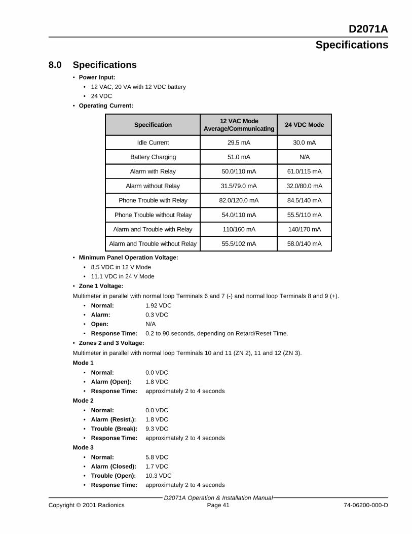
D2071A
D2071A Operation & Installation ManualCopyright © 2001 Radionics Page 41 74-06200-000-D
Specifications
8.0 Specifications• Power Input:
• 12 VAC, 20 VA with 12 VDC battery
• 24 VDC
• Operating Current:
Specification 12 VAC ModeAverage/Communicating
24 VDC Mode
Idle Current 29.5 mA 30.0 mA
Battery Charging 51.0 mA N/A
Alarm with Relay 50.0/110 mA 61.0/115 mA
Alarm without Relay 31.5/79.0 mA 32.0/80.0 mA
Phone Trouble with Relay 82.0/120.0 mA 84.5/140 mA
Phone Trouble without Relay 54.0/110 mA 55.5/110 mA
Alarm and Trouble with Relay 110/160 mA 140/170 mA
Alarm and Trouble without Relay 55.5/102 mA 58.0/140 mA
• Minimum Panel Operation Voltage:
• 8.5 VDC in 12 V Mode
• 11.1 VDC in 24 V Mode
• Zone 1 Voltage:
Multimeter in parallel with normal loop Terminals 6 and 7 (-) and normal loop Terminals 8 and 9 (+).
• Normal: 1.92 VDC
• Alarm: 0.3 VDC
• Open: N/A
• Response Time: 0.2 to 90 seconds, depending on Retard/Reset Time.
• Zones 2 and 3 Voltage:
Multimeter in parallel with normal loop Terminals 10 and 11 (ZN 2), 11 and 12 (ZN 3).
Mode 1
• Normal: 0.0 VDC
• Alarm (Open): 1.8 VDC
• Response Time: approximately 2 to 4 seconds
Mode 2
• Normal: 0.0 VDC
• Alarm (Resist.): 1.8 VDC
• Trouble (Break): 9.3 VDC
• Response Time: approximately 2 to 4 seconds
Mode 3
• Normal: 5.8 VDC
• Alarm (Closed): 1.7 VDC
• Trouble (Open): 10.3 VDC
• Response Time: approximately 2 to 4 seconds
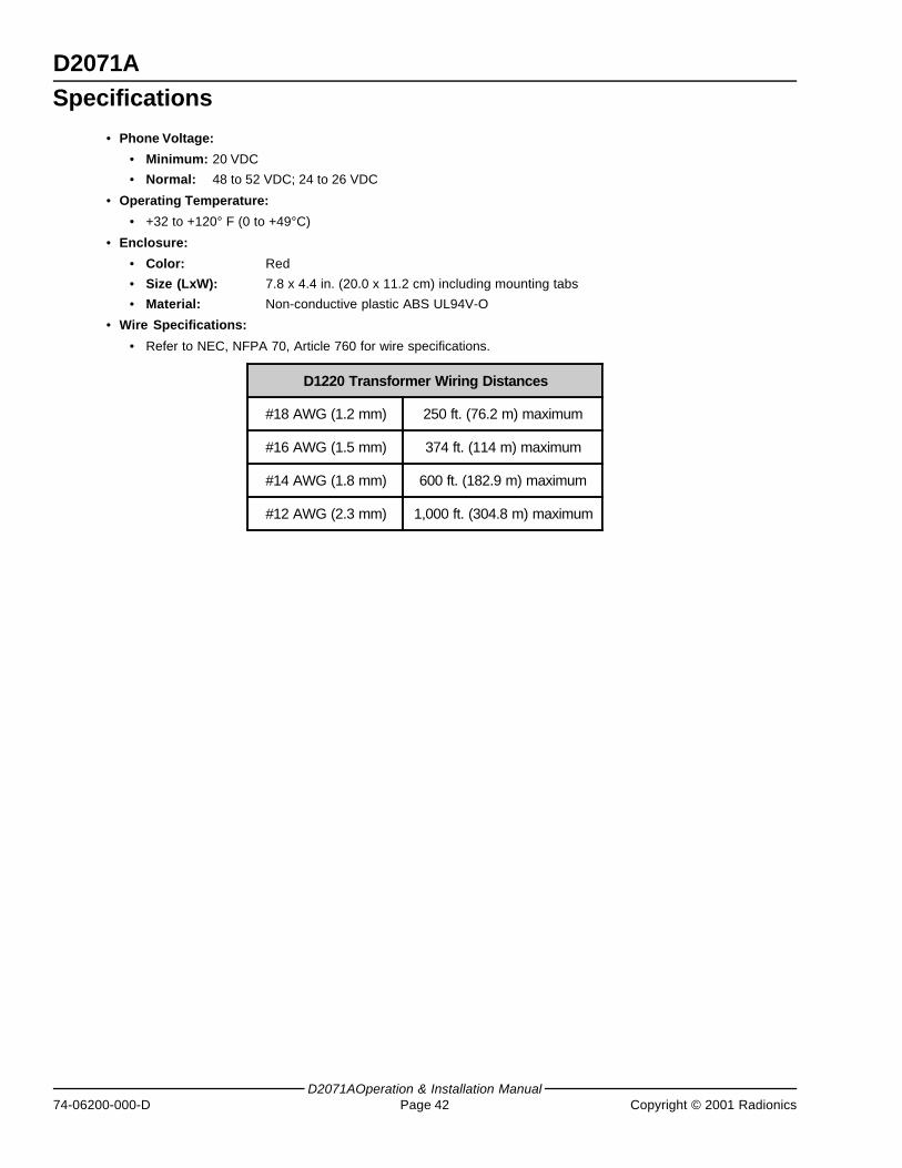
D2071A
D2071AOperation & Installation Manual74-06200-000-D Page 42 Copyright © 2001 Radionics
Specifications
• Phone Voltage:
• Minimum: 20 VDC
• Normal: 48 to 52 VDC; 24 to 26 VDC
• Operating Temperature:
• +32 to +120° F (0 to +49°C)
• Enclosure:
• Color: Red
• Size (LxW): 7.8 x 4.4 in. (20.0 x 11.2 cm) including mounting tabs
• Material: Non-conductive plastic ABS UL94V-O
• Wire Specifications:
• Refer to NEC, NFPA 70, Article 760 for wire specifications.
D1220 Transformer Wiring Distances
#18 AWG (1.2 mm) 250 ft. (76.2 m) maximum
#16 AWG (1.5 mm) 374 ft. (114 m) maximum
#14 AWG (1.8 mm) 600 ft. (182.9 m) maximum
#12 AWG (2.3 mm) 1,000 ft. (304.8 m) maximum
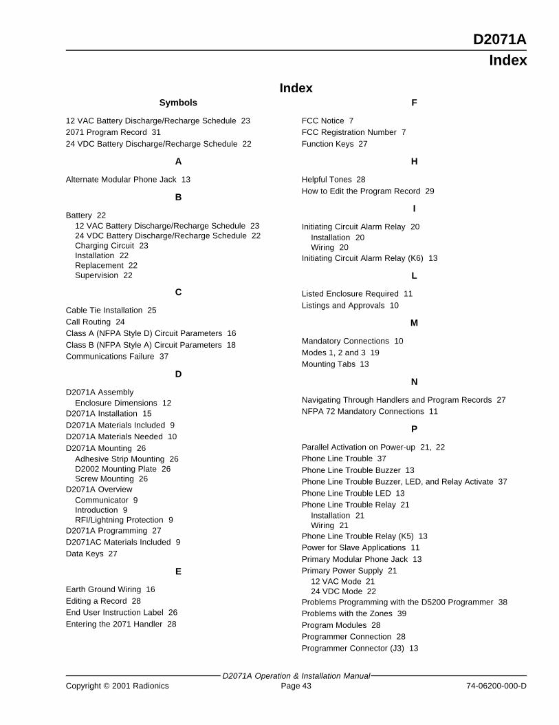
D2071A
D2071A Operation & Installation ManualCopyright © 2001 Radionics Page 43 74-06200-000-D
Index
Symbols
12 VAC Battery Discharge/Recharge Schedule 232071 Program Record 3124 VDC Battery Discharge/Recharge Schedule 22
A
Alternate Modular Phone Jack 13
B
Battery 2212 VAC Battery Discharge/Recharge Schedule 2324 VDC Battery Discharge/Recharge Schedule 22Charging Circuit 23Installation 22Replacement 22Supervision 22
C
Cable Tie Installation 25Call Routing 24Class A (NFPA Style D) Circuit Parameters 16Class B (NFPA Style A) Circuit Parameters 18Communications Failure 37
D
D2071A AssemblyEnclosure Dimensions 12
D2071A Installation 15D2071A Materials Included 9D2071A Materials Needed 10D2071A Mounting 26
Adhesive Strip Mounting 26D2002 Mounting Plate 26Screw Mounting 26
D2071A OverviewCommunicator 9Introduction 9RFI/Lightning Protection 9
D2071A Programming 27D2071AC Materials Included 9Data Keys 27
E
Earth Ground Wiring 16Editing a Record 28End User Instruction Label 26Entering the 2071 Handler 28
IndexF
FCC Notice 7FCC Registration Number 7Function Keys 27
H
Helpful Tones 28How to Edit the Program Record 29
I
Initiating Circuit Alarm Relay 20Installation 20Wiring 20
Initiating Circuit Alarm Relay (K6) 13
L
Listed Enclosure Required 11Listings and Approvals 10
M
Mandatory Connections 10Modes 1, 2 and 3 19Mounting Tabs 13
N
Navigating Through Handlers and Program Records 27NFPA 72 Mandatory Connections 11
P
Parallel Activation on Power-up 21, 22Phone Line Trouble 37Phone Line Trouble Buzzer 13Phone Line Trouble Buzzer, LED, and Relay Activate 37Phone Line Trouble LED 13Phone Line Trouble Relay 21
Installation 21Wiring 21
Phone Line Trouble Relay (K5) 13Power for Slave Applications 11Primary Modular Phone Jack 13Primary Power Supply 21
12 VAC Mode 2124 VDC Mode 22
Problems Programming with the D5200 Programmer 38Problems with the Zones 39Program Modules 28Programmer Connection 28Programmer Connector (J3) 13
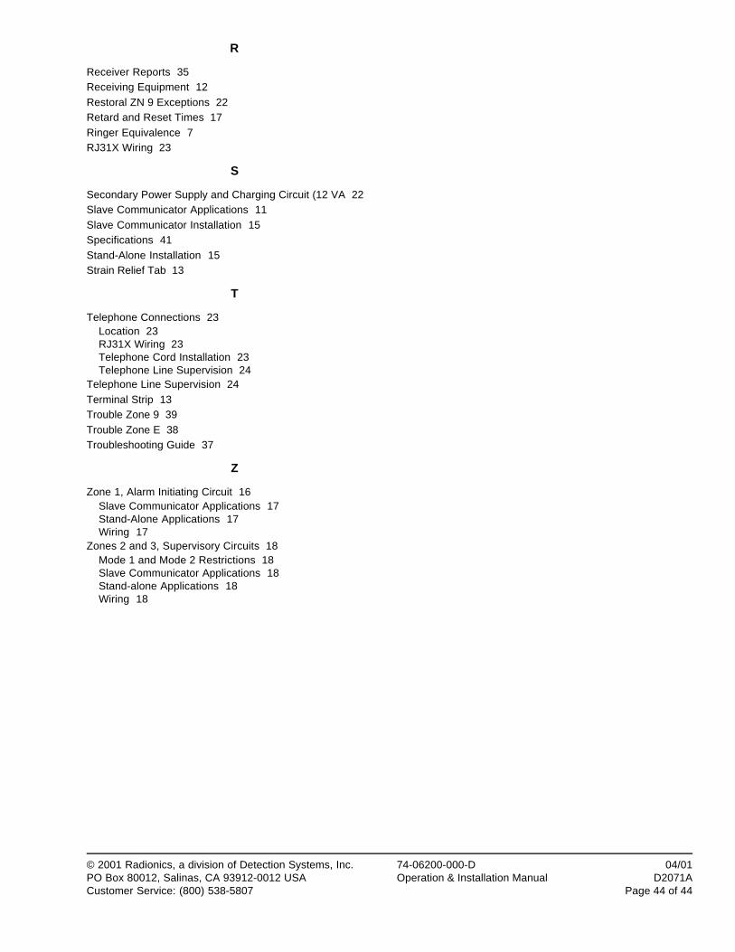
74-06200-000-D 04/01Operation & Installation Manual D2071A
Page 44 of 44
© 2001 Radionics, a division of Detection Systems, Inc.PO Box 80012, Salinas, CA 93912-0012 USACustomer Service: (800) 538-5807
R
Receiver Reports 35Receiving Equipment 12Restoral ZN 9 Exceptions 22Retard and Reset Times 17Ringer Equivalence 7RJ31X Wiring 23
S
Secondary Power Supply and Charging Circuit (12 VA 22Slave Communicator Applications 11Slave Communicator Installation 15Specifications 41Stand-Alone Installation 15Strain Relief Tab 13
T
Telephone Connections 23Location 23RJ31X Wiring 23Telephone Cord Installation 23Telephone Line Supervision 24
Telephone Line Supervision 24Terminal Strip 13Trouble Zone 9 39Trouble Zone E 38Troubleshooting Guide 37
Z
Zone 1, Alarm Initiating Circuit 16Slave Communicator Applications 17Stand-Alone Applications 17Wiring 17
Zones 2 and 3, Supervisory Circuits 18Mode 1 and Mode 2 Restrictions 18Slave Communicator Applications 18Stand-alone Applications 18Wiring 18