Embed Size (px)
Citation preview
Horizon 2020 PROGRAMME ICT-01-2014: Smart Cyber-Physical Systems This project has received funding from the European Union’s Horizon 2020 research and innovation programme under Grant Agreement No 643924
D2.4 Wireless and ancillary hardware BoM
Copyright © 2016 The EoT Consortium The opinions of the authors expressed in this document do not necessarily reflect the official opinion of EOT partners or of the European Commission.
1. DOCUMENT INFORMATION Deliverable Number D2.4 Deliverable Name Wireless and ancillary hardware BoM
Authors Alireza Dehghani (Movidius), Aubrey Dunne (Movidius),
David Moloney (Movidius), Oscar Deniz (UCLM)
Responsible Author Alireza Dehghani (Movidius)
e-mail: [email protected] phone: +353 86 1502011
WP WP2 Nature O Dissemination Level PU Final Version Date 29.02.2016 Reviewed by O. Deniz (UCLM)

D2.1 Prototype Board H2020-643924-EoT
Page 3 of 14 29/02/2016
2. DOCUMENT HISTORY
Person Date Comment Version
Alireza Dehghani 29.02.2016 Initial version 0.1
O. Deniz 1.03.2016 Review 0.2
D2.1 Prototype Board H2020-643924-EoT
Page 4 of 14 29/02/2016
3. TABLE OF CONTENTS 1. Document Information ........................................................................ 2 2. Document History .............................................................................. 3 3. Table of Contents ............................................................................... 4 4. Abstract ............................................................................................ 5 5. Wi-Fi Module ..................................................................................... 6
HW Setup and SW Configuration for 1st Development Prototype (MV0182) ............................................................................................... 7
5.1.1. CC3100BOOST setting and connection ....................................... 8
5.1.2. Level Shifter setting and connection .......................................... 9
5.1.3. MV0191 extension board setting and connection ......................... 9
5.1.4. MV0182 Boot Settings ........................................................... 10
5.1.5. CC3100MOD Considerations ................................................... 11
Bill Of Materials ............................................................................. 11 5.2.1. Hardware ............................................................................. 11
5.2.2. Software .............................................................................. 11
5.2.3. Online Resources .................................................................. 11
Software Deliverables .................................................................... 11 5.3.1. File Structure ....................................................................... 12
5.3.2. Running The Example Test ..................................................... 12
Wi-Fi CC3100BOOST module on EoT DevBoard ................................. 12

D2.1 Prototype Board H2020-643924-EoT
Page 5 of 14 29/02/2016
4. ABSTRACT Currently efficient options exist for low-power connectivity such as Zigbee and the more recent Bluetooth LE (low-energy). However, video streaming is not supported due to low bandwidth. EoT aims at being both interoperable and flexible, so video streaming must be possible (although not always desirable). EoT will use TCP/IP over Wi-Fi, since it supports video streaming and is widely deployed. Video compression (which can be performed efficiently with the video processor) and low-power features present in the latest Wi-Fi modules prepared for the Internet of Things will be leveraged, having low-power standby modes and fast wake-up times. This brief report describes EoT Wi-Fi deliverable.
D2.1 Prototype Board H2020-643924-EoT
Page 6 of 14 29/02/2016
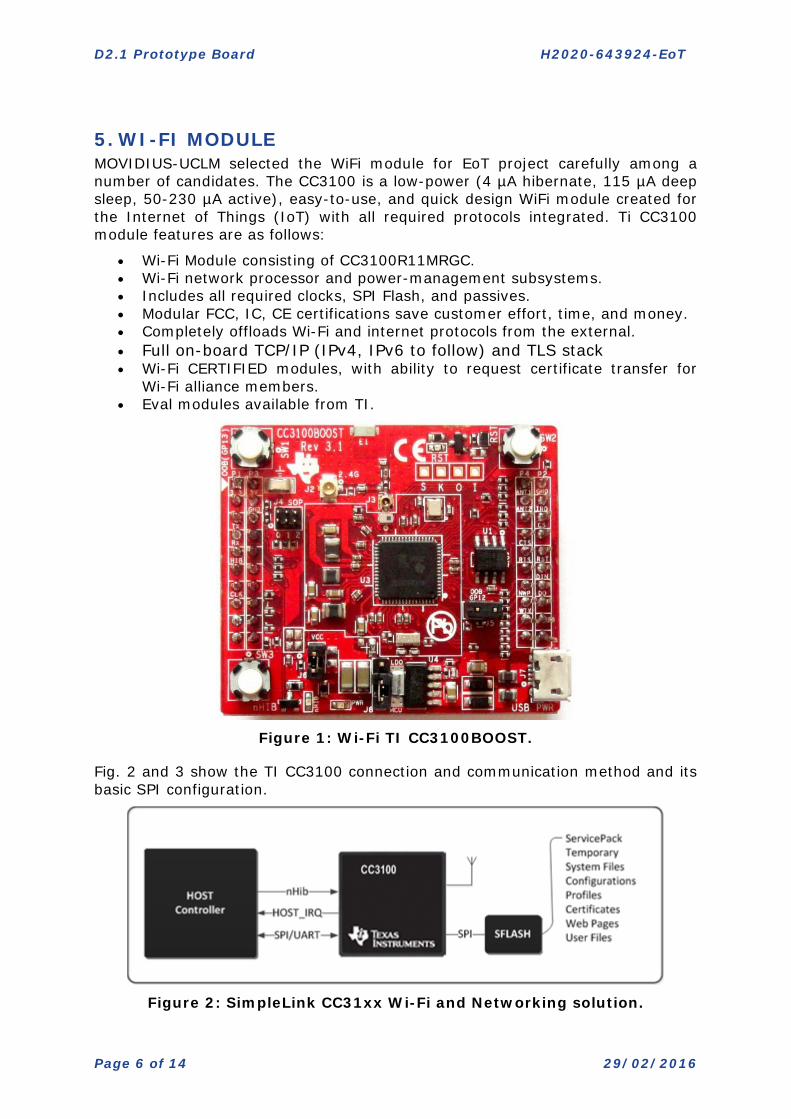
5. WI-FI MODULE MOVIDIUS-UCLM selected the WiFi module for EoT project carefully among a number of candidates. The CC3100 is a low-power (4 µA hibernate, 115 µA deep sleep, 50-230 µA active), easy-to-use, and quick design WiFi module created for the Internet of Things (IoT) with all required protocols integrated. Ti CC3100 module features are as follows:
• Wi-Fi Module consisting of CC3100R11MRGC. • Wi-Fi network processor and power-management subsystems. • Includes all required clocks, SPI Flash, and passives. • Modular FCC, IC, CE certifications save customer effort, time, and money. • Completely offloads Wi-Fi and internet protocols from the external. • Full on-board TCP/IP (IPv4, IPv6 to follow) and TLS stack • Wi-Fi CERTIFIED modules, with ability to request certificate transfer for
Wi-Fi alliance members. • Eval modules available from TI.
Figure 1: Wi-Fi TI CC3100BOOST.
Fig. 2 and 3 show the TI CC3100 connection and communication method and its basic SPI configuration.
Figure 2: SimpleLink CC31xx Wi-Fi and Networking solution.
D2.1 Prototype Board H2020-643924-EoT
Page 7 of 14 29/02/2016
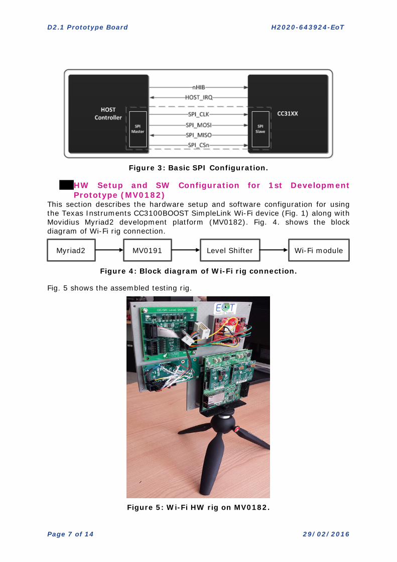
Figure 3: Basic SPI Configuration.
HW Setup and SW Configuration for 1st Development Prototype (MV0182)
This section describes the hardware setup and software configuration for using the Texas Instruments CC3100BOOST SimpleLink Wi-Fi device (Fig. 1) along with Movidius Myriad2 development platform (MV0182). Fig. 4. shows the block diagram of Wi-Fi rig connection.
Figure 4: Block diagram of Wi-Fi rig connection.
Fig. 5 shows the assembled testing rig.
Figure 5: Wi-Fi HW rig on MV0182.
Myriad2 MV0191 Level Shifter Wi-Fi module
D2.1 Prototype Board H2020-643924-EoT
Page 8 of 14 29/02/2016
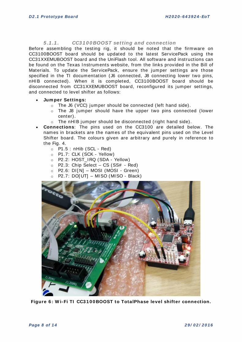
5.1.1. CC3100BOOST setting and connection
Before assembling the testing rig, it should be noted that the firmware on CC3100BOOST board should be updated to the latest ServicePack using the CC31XXEMUBOOST board and the UniFlash tool. All software and instructions can be found on the Texas Instruments website, from the links provided in the Bill of Materials. To update the ServicePack, ensure the jumper settings are those specified in the TI documentation (J6 connected, J8 connecting lower two pins, nHIB connected). When it is completed, CC3100BOOST board should be disconnected from CC31XXEMUBOOST board, reconfigured its jumper settings, and connected to level shifter as follows:
• Jumper Settings: o The J6 (VCC) jumper should be connected (left hand side). o The J8 jumper should have the upper two pins connected (lower
center). o The nHIB jumper should be disconnected (right hand side).
• Connections: The pins used on the CC3100 are detailed below. The names in brackets are the names of the equivalent pins used on the Level Shifter board. The colours given are arbitrary and purely in reference to the Fig. 4.
o P1.5 : nHib (SCL - Red) o P1.7: CLK (SCK - Yellow) o P2.2: HOST_IRQ (SDA - Yellow) o P2.3: Chip Select – CS (SS# - Red) o P2.6: DI[N] – MOSI (MOSI - Green) o P2.7: DO[UT] – MISO (MISO - Black)
Figure 6: Wi-Fi TI CC3100BOOST to TotalPhase level shifter connection.
D2.1 Prototype Board H2020-643924-EoT
Page 9 of 14 29/02/2016
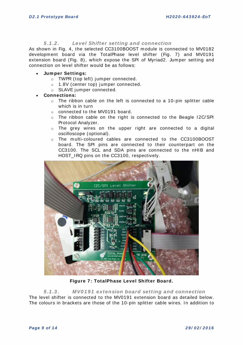
5.1.2. Level Shifter setting and connection
As shown in Fig. 4, the selected CC3100BOOST module is connected to MV0182 development board via the TotalPhase level shifter (Fig. 7) and MV0191 extension board (Fig. 8), which expose the SPI of Myriad2. Jumper setting and connection on level shifter would be as follows:
• Jumper Settings: o TWPR (top left) jumper connected. o 1.8V (center top) jumper connected. o SLAVE jumper connected.
• Connections: o The ribbon cable on the left is connected to a 10-pin splitter cable
which is in turn o connected to the MV0191 board. o The ribbon cable on the right is connected to the Beagle I2C/SPI
Protocol Analyzer. o The grey wires on the upper right are connected to a digital
oscilloscope (optional). o The multi-coloured cables are connected to the CC3100BOOST
board. The SPI pins are connected to their counterpart on the CC3100. The SCL and SDA pins are connected to the nHIB and HOST_IRQ pins on the CC3100, respectively.
Figure 7: TotalPhase Level Shifter Board.
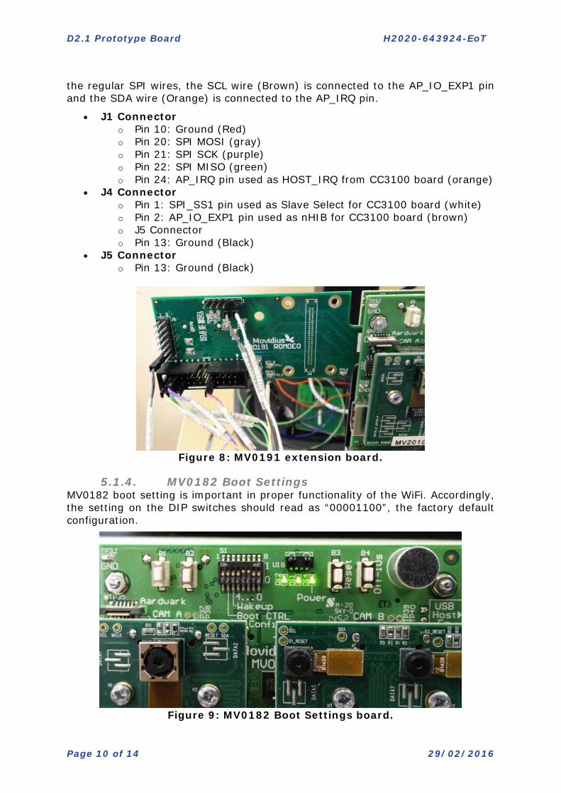
5.1.3. MV0191 extension board setting and connection The level shifter is connected to the MV0191 extension board as detailed below. The colours in brackets are those of the 10-pin splitter cable wires. In addition to
D2.1 Prototype Board H2020-643924-EoT
Page 10 of 14 29/02/2016
the regular SPI wires, the SCL wire (Brown) is connected to the AP_IO_EXP1 pin and the SDA wire (Orange) is connected to the AP_IRQ pin.
• J1 Connector o Pin 10: Ground (Red) o Pin 20: SPI MOSI (gray) o Pin 21: SPI SCK (purple) o Pin 22: SPI MISO (green) o Pin 24: AP_IRQ pin used as HOST_IRQ from CC3100 board (orange)
• J4 Connector o Pin 1: SPI_SS1 pin used as Slave Select for CC3100 board (white) o Pin 2: AP_IO_EXP1 pin used as nHIB for CC3100 board (brown) o J5 Connector o Pin 13: Ground (Black)
• J5 Connector o Pin 13: Ground (Black)
Figure 8: MV0191 extension board.
5.1.4. MV0182 Boot Settings MV0182 boot setting is important in proper functionality of the WiFi. Accordingly, the setting on the DIP switches should read as “00001100”, the factory default configuration.
Figure 9: MV0182 Boot Settings board.

D2.1 Prototype Board H2020-643924-EoT
Page 11 of 14 29/02/2016
5.1.5. CC3100MOD Considerations Although this document describes the usage of a CC3100BOOST board, it is functionally equivalent to a CC3100MOD connected to a CC3100MODBOOST board. A minor difference is that on the HOST_IRQ pin is referred to as HOST_INTR on the CC3100MOD. The CC31XXEMUBOOST board can be used with either the CC3100BOOST or CC3100MODBOOST boards, as per the TI documentation.
Bill Of Materials The bill of materials, HW, SW, online resources, and deliverable software for the Wi-Fi rig is listed as follows:
5.2.1. Hardware • Movidius Myriad2 Development Kit (MV0182 R3M0E0) • Movidius MV0191 Extension Board (R0M0E0) • TotalPhase Level Shifter Board
o http://www.totalphase.com/products/level-shifter/ • TotalPhase Beagle I2C/SPI Protocol Analyzer
o http://www.totalphase.com/products/beagle-i2cspi/ • TotalPhase Splitter Cable
o http://www.totalphase.com/products/split-cable/ • Texas Instruments SimpleLink WiFi CC3100 BoosterPack
o http://www.ti.com/tool/cc3100boost • Texas Instruments CC31XXEMUBOOST Board
o http://www.ti.com/tool/CC31XXEMUBOOST • Misc cables for connecting board pins
5.2.2. Software
• Movidius MDK 15.02.0 • Total Phase Data Center
o http://www.totalphase.com/products/data-center/ • Texas Instruments UniFlash Tool + Latest CC3100 ServicePack
o http://processors.wiki.ti.com/index.php/CC31xx_%26_CC32xx_SimpleLink_Tools#UniFlash
o http://processors.wiki.ti.com/index.php/CC31xx_Release_Notes
5.2.3. Online Resources • Level Shifter Board Manual
o http://www.totalphase.com/support/articles/200397858 • CC31XX Wiki
o http://processors.wiki.ti.com/index.php/CC31xx_%26_CC32xx • Movidius Developer Support https://www.movidius.org/ • Wi-Fi Driver Software https://github.com/CTOmovidius/MvEoT
Software Deliverables The Myriad2 port of the SimpleLink Wi-Fi Host driver software is available on GitHub for cloning or downloading (link provided in previous section). The code is organized in the traditional manner for Myriad2 development using the MDK 15.02.0 release. The driver and example code can be found in the mdk/emdalo/wifi_driver directory, the structure of which is described below.
D2.1 Prototype Board H2020-643924-EoT
Page 12 of 14 29/02/2016
5.3.1. File Structure Makefile Top level Makefile for tests config/ Myriad2 build scripts doc/ Documentation leon/ app_config.c Myriad2 configuration functions app_config.h Myriad2 configuration header get_time.c CC3100 get SNTP Time example (AP)
main.c Main code entry point sl_common.h CC3100 common example definitions simplelink/ Myriad2 port of CC3100 SPI Host Driver board.c Test Rig configuration and setup functions board.h Test Rig configuration and setup header cli_uart.h Command Line Interface macro definitions spi.c Myriad2 SPI Master port for SimpleLink Host
driver spi.h Myriad2 SPI Master driver public interface user.h Configuration of SimpleLink Host driver
definitions include/ CC3100 SimpleLink Host Driver header files source/ CC3100 SimpleLink Host Driver source code output/ Output directory for build system
5.3.2. Running The Example Test The simplest example to run is the get_time example from the TI CC3100 Software Development Kit (v1.1.0). This example connects to a local wireless network and then contacts an NTP server to get the current time. Before running the test, you must edit the sl_common.h header file and edit the SSID_NAME, SEC_TYPE and PASSKEY definitions to match those of your local wireless network. Once the testing rig has been assembled and powered-up (including the Myriad2 JTAG debugged), start the moviDebugServer by running “make start_server” in the wifi_driver directory. The get_time test can now be run via “make run” in the wifi_driver directory (in a different terminal/window from the start_server one).
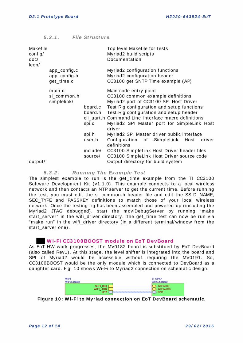
Wi-Fi CC3100BOOST module on EoT DevBoard
As EoT HW work progresses, the MV0182 board is substitued by EoT DevBoard (also called Rev1). At this stage, the level shifter is integrated into the board and SPI of Myriad2 would be accessible without requiring the MV0191. So, CC3100BOOST would be the only module which is connected to DevBoard as a daughter card. Fig. 10 shows Wi-Fi to Myriad2 connection on schematic design.
Figure 10: Wi-Fi to Myriad connection on EoT DevBoard schematic.
D2.1 Prototype Board H2020-643924-EoT
Page 13 of 14 29/02/2016
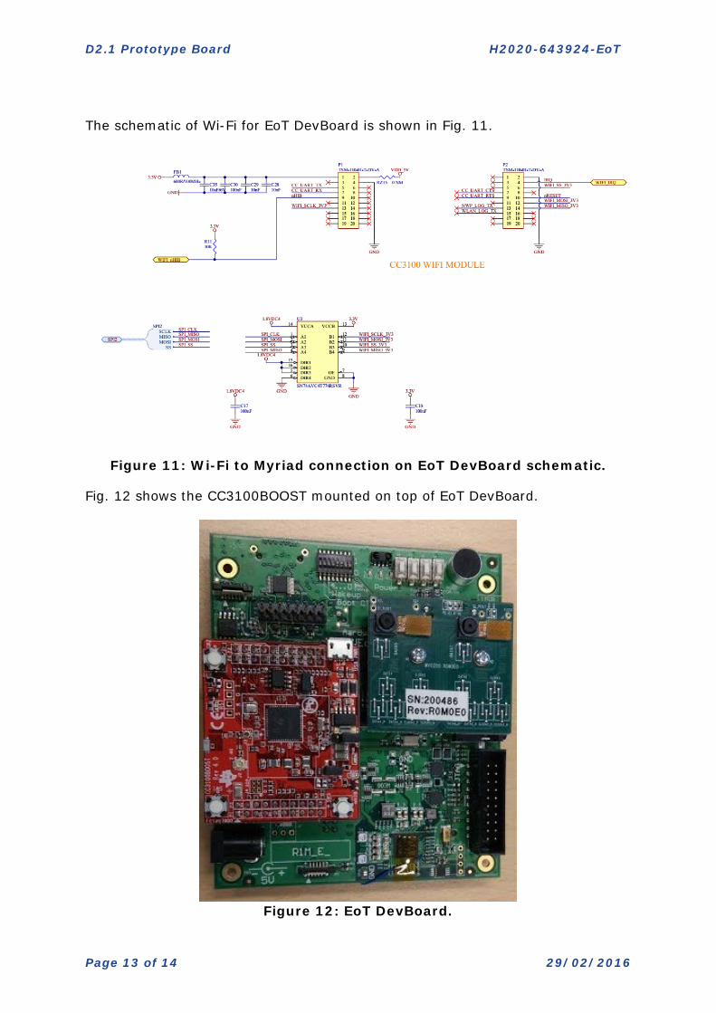
The schematic of Wi-Fi for EoT DevBoard is shown in Fig. 11.
Figure 11: Wi-Fi to Myriad connection on EoT DevBoard schematic.
Fig. 12 shows the CC3100BOOST mounted on top of EoT DevBoard.
Figure 12: EoT DevBoard.

D2.1 Prototype Board H2020-643924-EoT
Page 14 of 14 29/02/2016
- End of document -