Embed Size (px)
Citation preview
D115 – The Fast Optimal
Servo Amplifier For Brush, Brushless, Voice Coil Servo Motors
Ron Boe
5/15/2014
This user guide details the servo drives capabilities and physical interfaces. Users will be able to
evaluate the applicability to the user requirements and enable the user to hook up and use the servo
drive.
D115 Quick Start and Host Guide Page 1
Revision History
Document Number Description Date
3500500060 Rev - Initial Release Sept, 18, 2015
Important Notice
This document is subject to the following conditions and restrictions:
• This document contains proprietary information belonging to Servo Dynamics. This information is provided for the purpose of assisting users of the servo drive in
its installation.
• The text and graphics in this document are for the purpose of illustration and
reference only.
• The information in this document is subject to change without notice.
D115 Quick Start and Host Guide Page 2
Contents 1 Introduction .......................................................................................................................................... 3
1.1 Description .................................................................................................................................... 3
1.1 Technical Specifications .............................................................................................................. 4
2 Safety Information .............................................................................................................................. 6
2.1 Electrical Cautions ........................................................................................................................ 6
3 Connector Information ...................................................................................................................... 6
3.1 P1 Terminal Block / Power Connector .......................................................................................... 6
3.2 P2 Connector 37 pin ...................................................................................................................... 7
3.3 Mounting Dimensions .................................................................................................................. 8
4 Application Guide .................................................................................................................................. 9
4.1 Input Power ................................................................................................................................... 9
4.2 Analog Command and 4 to 20mA Command Input ...................................................................... 9
4.3 Auxiliary Analog Input (Feedback) .............................................................................................. 10
4.4 Digital Inputs ............................................................................................................................... 10
4.4.1 Enable Input and Mode Select Inputs ................................................................................. 10
4.4.2 Hall Input and Encoder Inputs ............................................................................................ 11
4.4.3 Home Find and Sync In ........................................................................................................ 11
4.5 Digital Outputs ............................................................................................................................ 12
4.6 Low Side High Current Drive ....................................................................................................... 12
4.7 Motor Thermistor Interface ........................................................................................................ 12
4.8 RS485 Interface ........................................................................................................................... 13
4.9 USB Interface .............................................................................................................................. 13
4.10 LED Status Signals ....................................................................................................................... 13
5 Contact Information ........................................................................................................................ 13
D115 Quick Start and Host Guide Page 3
1 Introduction
This information manual provides the product specifications, wiring diagram, operational modes
(Position, velocity, torque and PWM) and troubleshooting procedures for the D115-Fast
Optimal Drive.
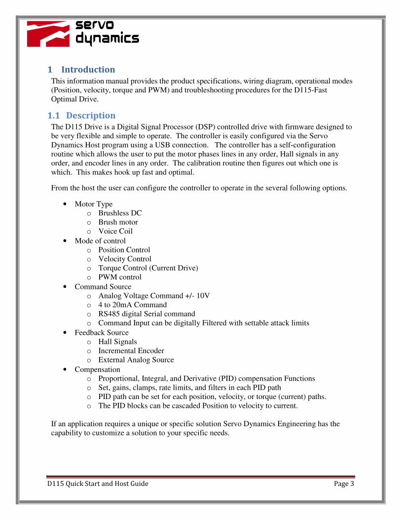
1.1 Description
The D115 Drive is a Digital Signal Processor (DSP) controlled drive with firmware designed to
be very flexible and simple to operate. The controller is easily configured via the Servo
Dynamics Host program using a USB connection. The controller has a self-configuration
routine which allows the user to put the motor phases lines in any order, Hall signals in any
order, and encoder lines in any order. The calibration routine then figures out which one is
which. This makes hook up fast and optimal.
From the host the user can configure the controller to operate in the several following options.
• Motor Type
o Brushless DC
o Brush motor
o Voice Coil
• Mode of control
o Position Control
o Velocity Control
o Torque Control (Current Drive)
o PWM control
• Command Source
o Analog Voltage Command +/- 10V
o 4 to 20mA Command
o RS485 digital Serial command
o Command Input can be digitally Filtered with settable attack limits
• Feedback Source
o Hall Signals
o Incremental Encoder
o External Analog Source
• Compensation
o Proportional, Integral, and Derivative (PID) compensation Functions
o Set, gains, clamps, rate limits, and filters in each PID path
o PID path can be set for each position, velocity, or torque (current) paths.
o The PID blocks can be cascaded Position to velocity to current.
If an application requires a unique or specific solution Servo Dynamics Engineering has the
capability to customize a solution to your specific needs.
D115 Quick Start and Host Guide Page 4
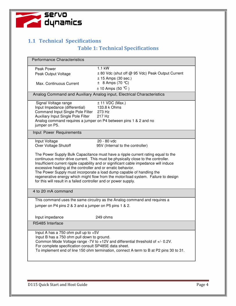
1.1 Technical Specifications
Table 1: Technical Specifications
Performance Characteristics
Peak Power 1.1 kW
Peak Output Voltage ± 80 Vdc (shut off @ 95 Vdc) Peak Output Current
± 15 Amps (30 sec.)
Max. Continuous Current ± 8 Amps (70 °C)
± 10 Amps (50 °C )
Analog Command and Auxiliary Analog input, Electrical Characteristics
Signal Voltage range ± 11 VDC (Max.) Input Impedance (differential) 133.8 k Ohms Command Input Single Pole Filter 273 Hz Auxiliary Input Single Pole Filter 217 Hz Analog command requires a jumper on P4 between pins 1 & 2 and no jumper on P5.
Input Power Requirements
Input Voltage 20 - 80 vdc Over Voltage Shutoff 95V (Internal to the controller) The Power Supply Bulk Capacitance must have a ripple current rating equal to the continuous motor drive current. This must be physically close to the controller. Insufficient current ripple capability and or significant cable impedance will induce excessive heating at the controller and or erratic behavior. The Power Supply must incorporate a load dump capable of handling the regenerative energy which might flow from the motor/load system. Failure to design for this will result in a failed controller and or power supply.
4 to 20 mA command
This command uses the same circuitry as the Analog command and requires a
jumper on P4 pins 2 & 3 and a jumper on P5 pins 1 & 2.
Input impedance 249 ohms
RS485 Interface
Input A has a 750 ohm pull up to +5V Input B has a 750 ohm pull down to ground. Common Mode Voltage range -7V to +12V and differential threshold of +/- 0.2V. For complete specification consult SP485E data sheet. To implement end of line 150 ohm termination, connect A-term to B at P2 pins 30 to 31.

D115 Quick Start and Host Guide Page 5
Digital Inputs
• Hall inputs, Quadrature Encoder Inputs, have 1K pull up resistors to 5V.
• Hall and Encoder inputs maximum pulse frequency is 1MHz.
• Digital Inputs have an internal 4.7K resistor pull up to +5V. Din 1 thru 4 are on P2-15, 33, 14, and
32 respectively.
• Enable function is dedicated to Din 4. The controller only enables on a transition from off to on
to prevent unexpected motion on power up. Controller enables from open (High) to closed
(low).
• Sync In and Home Find have a 4.7K resistor pull up to 3.3V.
• Sync in function will hold off mode changes when held low. This allows configuration changes to
be synchronized between multiple controllers.
• Home Find - When controller is placed in home find mode and external switch is selected to
determine home position the controller will look for this input to be pulled low. When this
occurs the controller sets the position count to zero and stops the home find movement.
Digital and Discrete Outputs
• Digital out 1 and 2 are 5V logic levels with a 100 ohm source impedance.
• Low Drive 1 and 2 are open collector 60V MOSFETS for use in driving external loads.
• Low Drive 1 and 2 are rated for 1.4A each over the entire temperature range.
Motor Thermistor Sense
The motor thermistor interface is designed to interface to Vishay BC Components part number
NTCLE203E3104GBO. This will provide 5% accurate temperature monitoring. If the motor has a
normally open thermo switch the terminals can be connected between the sense input and ground.
The closing of the thermo switch would trip a temperature threshold set via the host software and
parameter file.
5V power for Hall and Encoder
5V (4.7V to 5.1V) at 125mA nominal.
Short Circuit Protection – indefinite.
Physical Characteristics
Module Dimensions (L x W x H) 5.4 in. x 1.0 in. x 3.2 in.
Weight 0.70 lb.
Ambient Temperature – Operating 0 °C to 50 °C Shutdown Temperature 80 °C at heat sink Relative Humidity 5 - 95% non-condensing
D115 Quick Start and Host Guide Page 6
2 Safety Information
2.1 Electrical Cautions
• Ensure that the negative terminal of the bus capacitor is grounded to the earth ground.
Improper grounding may cause erratic operation or a safety hazard due to common
mode voltages.
• An isolation step-down transformer or isolated regulated supply must be used for the
power supply of this unit.
• Make sure that all voltages and tests are made with battery powered or
electrically isolated instruments.
3 Connector Information
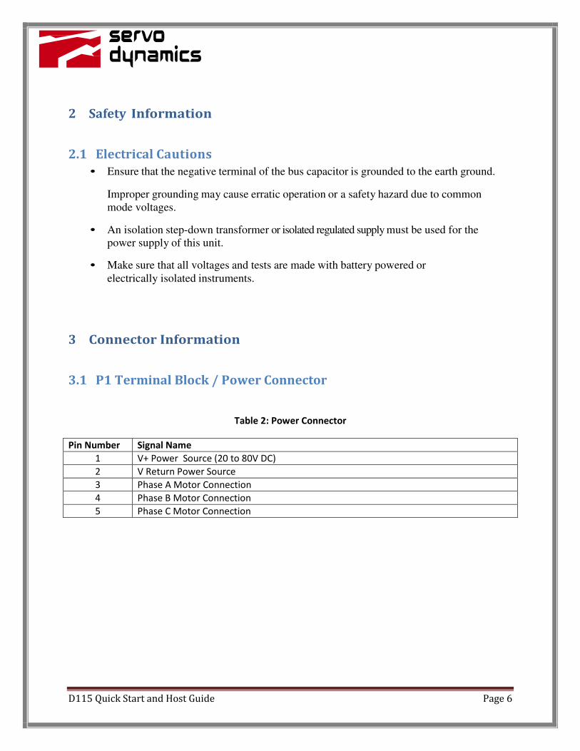
3.1 P1 Terminal Block / Power Connector
Table 2: Power Connector
Pin Number Signal Name
1 V+ Power Source (20 to 80V DC)
2 V Return Power Source
3 Phase A Motor Connection
4 Phase B Motor Connection
5 Phase C Motor Connection
D115 Quick Start and Host Guide Page 7
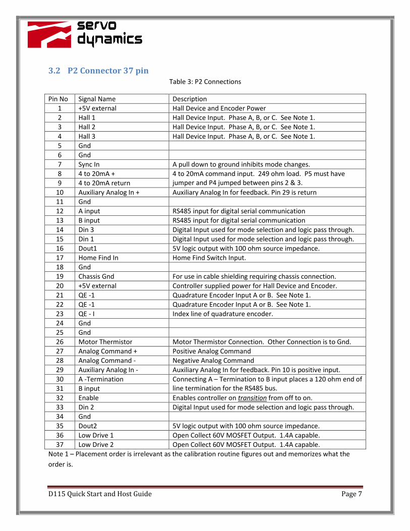
3.2 P2 Connector 37 pin
Table 3: P2 Connections
Pin No Signal Name Description
1 +5V external Hall Device and Encoder Power
2 Hall 1 Hall Device Input. Phase A, B, or C. See Note 1.
3 Hall 2 Hall Device Input. Phase A, B, or C. See Note 1.
4 Hall 3 Hall Device Input. Phase A, B, or C. See Note 1.
5 Gnd
6 Gnd
7 Sync In A pull down to ground inhibits mode changes.
8 4 to 20mA + 4 to 20mA command input. 249 ohm load. P5 must have
jumper and P4 jumped between pins 2 & 3. 9 4 to 20mA return
10 Auxiliary Analog In + Auxiliary Analog In for feedback. Pin 29 is return
11 Gnd
12 A input RS485 input for digital serial communication
13 B input RS485 input for digital serial communication
14 Din 3 Digital Input used for mode selection and logic pass through.
15 Din 1 Digital Input used for mode selection and logic pass through.
16 Dout1 5V logic output with 100 ohm source impedance.
17 Home Find In Home Find Switch Input.
18 Gnd
19 Chassis Gnd For use in cable shielding requiring chassis connection.
20 +5V external Controller supplied power for Hall Device and Encoder.
21 QE -1 Quadrature Encoder Input A or B. See Note 1.
22 QE -1 Quadrature Encoder Input A or B. See Note 1.
23 QE - I Index line of quadrature encoder.
24 Gnd
25 Gnd
26 Motor Thermistor Motor Thermistor Connection. Other Connection is to Gnd.
27 Analog Command + Positive Analog Command
28 Analog Command - Negative Analog Command
29 Auxiliary Analog In - Auxiliary Analog In for feedback. Pin 10 is positive input.
30 A -Termination Connecting A – Termination to B input places a 120 ohm end of
line termination for the RS485 bus. 31 B input
32 Enable Enables controller on transition from off to on.
33 Din 2 Digital Input used for mode selection and logic pass through.
34 Gnd
35 Dout2 5V logic output with 100 ohm source impedance.
36 Low Drive 1 Open Collect 60V MOSFET Output. 1.4A capable.
37 Low Drive 2 Open Collect 60V MOSFET Output. 1.4A capable.
Note 1 – Placement order is irrelevant as the calibration routine figures out and memorizes what the
order is.
D115 Quick Start and Host Guide Page 8
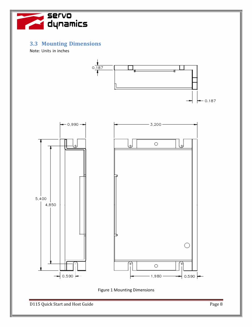
3.3 Mounting Dimensions Note: Units in inches
Figure 1 Mounting Dimensions
D115 Quick Start and Host Guide Page 9
4 Application Guide
4.1 Input Power
The input power for any servo motor drive system must take into account the current surges both
positive and negative along with continuous ripple current.
If the supply cannot supply the surge which occurs during acceleration the supply voltage will drop
below the minimum and the controller may reset. In the condition of the servo drive slows or reverses a
motor with an aiding load the motor will generate power back through the controller to the input
power. If the voltage pumps beyond 100V, components internal to the drive will catastrophically fail.
Therefore an adequately sized load dump circuit with appropriately selected trip level must be included
in the system power source.
Ripple current occurs at 20KHz which is the power stage switching frequency. The internal capacitance
is rated for 1Arms continuous. The power supply should have adequate capacitance and ripple current
rating to the system continuous operation. The power supply should be placed as close as possible to
the controller to ensure the parasitic cable impedance does not limit the continuous ripple current.
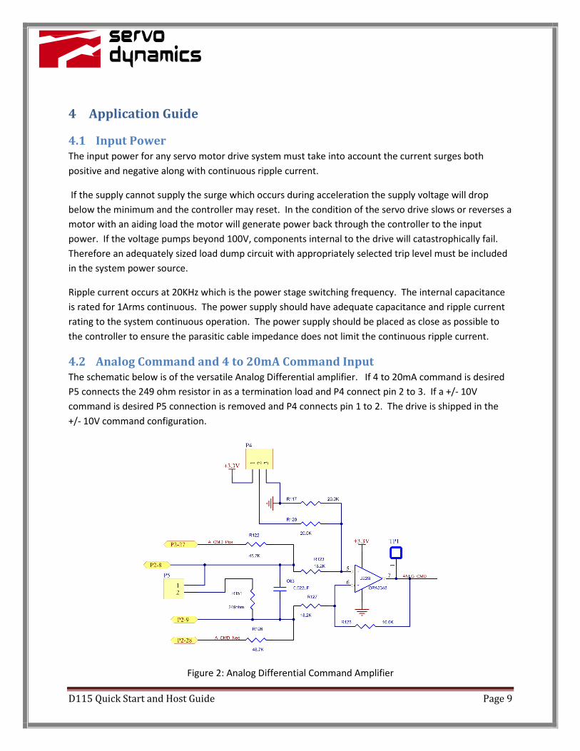
4.2 Analog Command and 4 to 20mA Command Input
The schematic below is of the versatile Analog Differential amplifier. If 4 to 20mA command is desired
P5 connects the 249 ohm resistor in as a termination load and P4 connect pin 2 to 3. If a +/- 10V
command is desired P5 connection is removed and P4 connects pin 1 to 2. The drive is shipped in the
+/- 10V command configuration.
Figure 2: Analog Differential Command Amplifier
D115 Quick Start and Host Guide Page 10
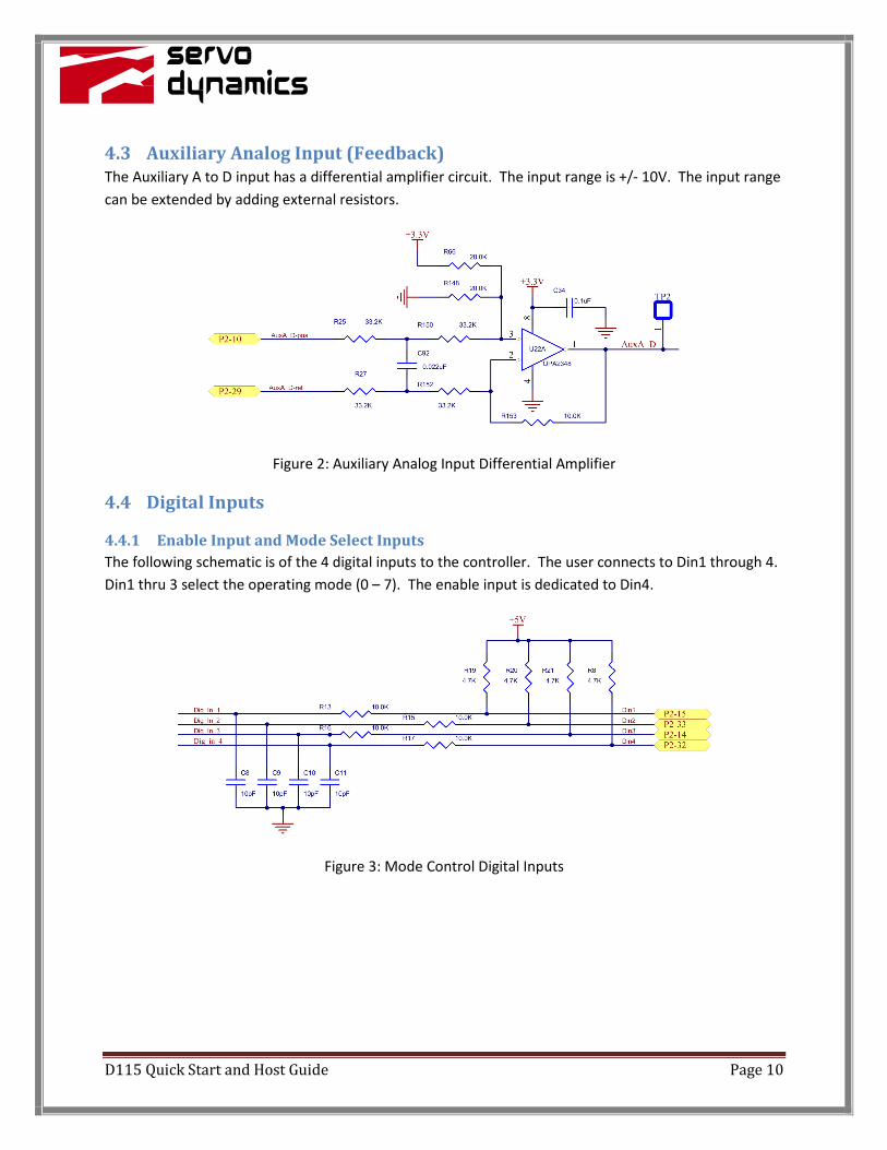
4.3 Auxiliary Analog Input (Feedback)
The Auxiliary A to D input has a differential amplifier circuit. The input range is +/- 10V. The input range
can be extended by adding external resistors.
Figure 2: Auxiliary Analog Input Differential Amplifier
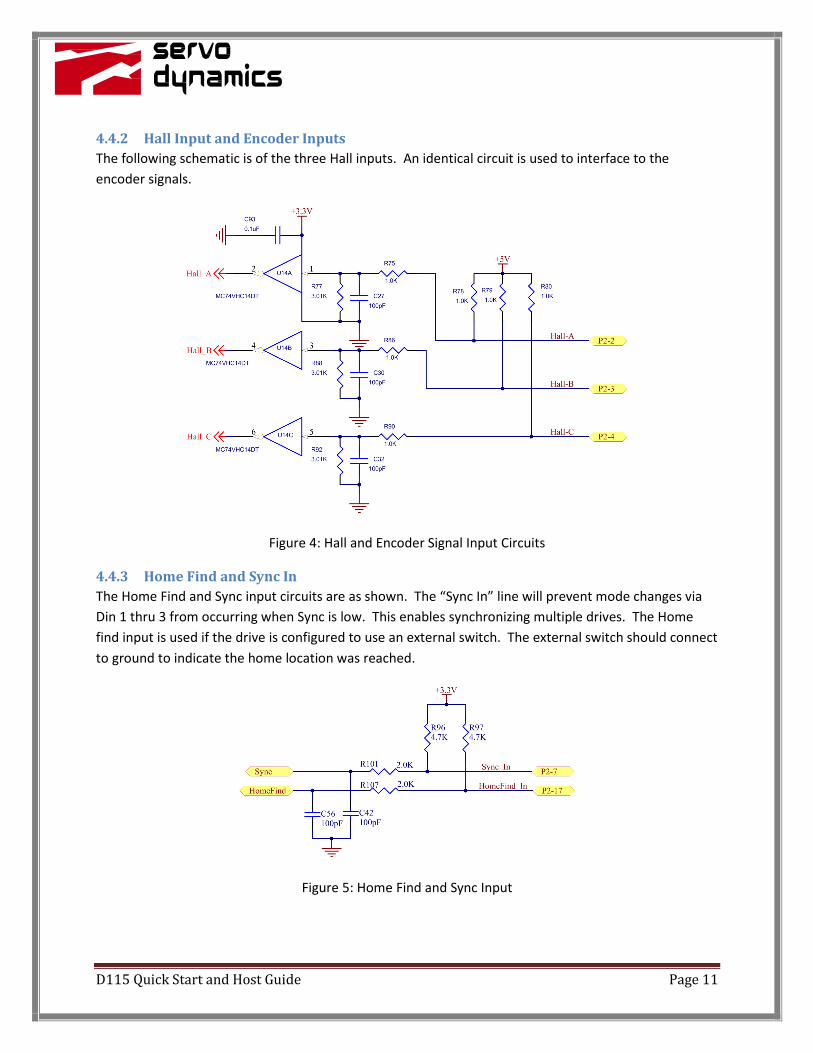
4.4 Digital Inputs
4.4.1 Enable Input and Mode Select Inputs
The following schematic is of the 4 digital inputs to the controller. The user connects to Din1 through 4.
Din1 thru 3 select the operating mode (0 – 7). The enable input is dedicated to Din4.
Figure 3: Mode Control Digital Inputs
D115 Quick Start and Host Guide Page 11
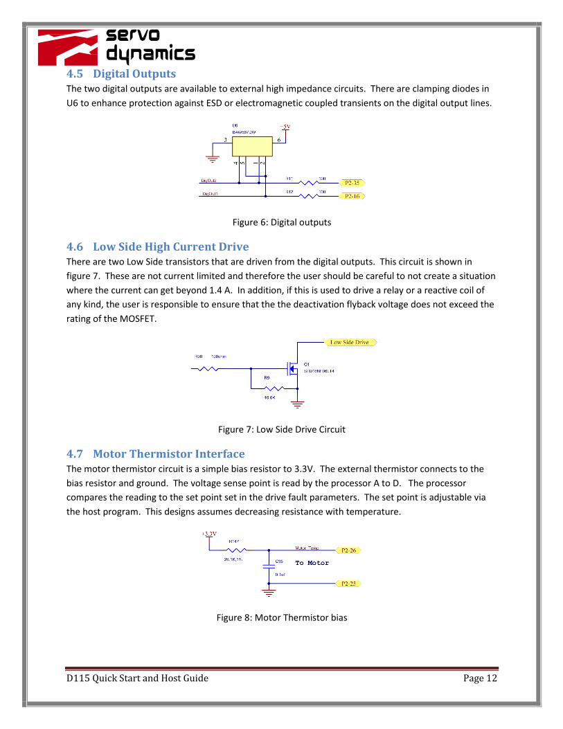
4.4.2 Hall Input and Encoder Inputs
The following schematic is of the three Hall inputs. An identical circuit is used to interface to the
encoder signals.
Figure 4: Hall and Encoder Signal Input Circuits
4.4.3 Home Find and Sync In
The Home Find and Sync input circuits are as shown. The “Sync In” line will prevent mode changes via
Din 1 thru 3 from occurring when Sync is low. This enables synchronizing multiple drives. The Home
find input is used if the drive is configured to use an external switch. The external switch should connect
to ground to indicate the home location was reached.
Figure 5: Home Find and Sync Input
D115 Quick Start and Host Guide Page 12
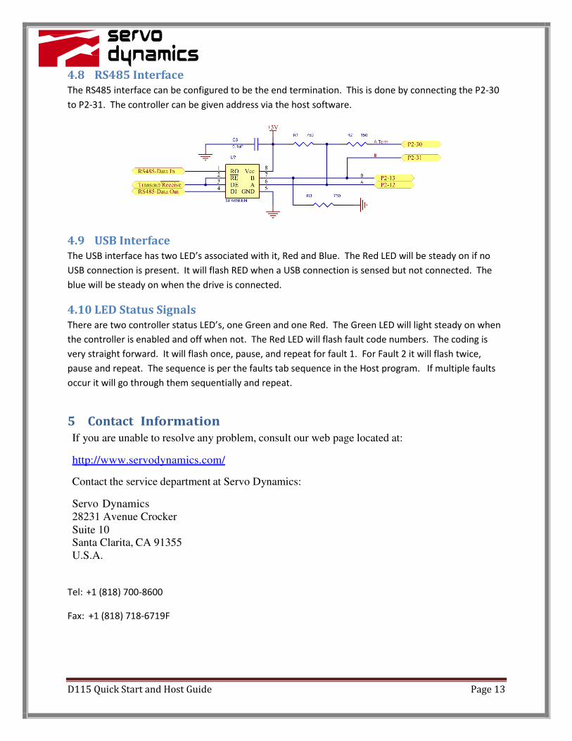
4.5 Digital Outputs
The two digital outputs are available to external high impedance circuits. There are clamping diodes in
U6 to enhance protection against ESD or electromagnetic coupled transients on the digital output lines.
Figure 6: Digital outputs
4.6 Low Side High Current Drive
There are two Low Side transistors that are driven from the digital outputs. This circuit is shown in
figure 7. These are not current limited and therefore the user should be careful to not create a situation
where the current can get beyond 1.4 A. In addition, if this is used to drive a relay or a reactive coil of
any kind, the user is responsible to ensure that the the deactivation flyback voltage does not exceed the
rating of the MOSFET.
Figure 7: Low Side Drive Circuit
4.7 Motor Thermistor Interface
The motor thermistor circuit is a simple bias resistor to 3.3V. The external thermistor connects to the
bias resistor and ground. The voltage sense point is read by the processor A to D. The processor
compares the reading to the set point set in the drive fault parameters. The set point is adjustable via
the host program. This designs assumes decreasing resistance with temperature.
Figure 8: Motor Thermistor bias
D115 Quick Start and Host Guide Page 13
4.8 RS485 Interface
The RS485 interface can be configured to be the end termination. This is done by connecting the P2-30
to P2-31. The controller can be given address via the host software.
4.9 USB Interface
The USB interface has two LED’s associated with it, Red and Blue. The Red LED will be steady on if no
USB connection is present. It will flash RED when a USB connection is sensed but not connected. The
blue will be steady on when the drive is connected.
4.10 LED Status Signals
There are two controller status LED’s, one Green and one Red. The Green LED will light steady on when
the controller is enabled and off when not. The Red LED will flash fault code numbers. The coding is
very straight forward. It will flash once, pause, and repeat for fault 1. For Fault 2 it will flash twice,
pause and repeat. The sequence is per the faults tab sequence in the Host program. If multiple faults
occur it will go through them sequentially and repeat.
5 Contact Information
If you are unable to resolve any problem, consult our web page located at:
http://www.servodynamics.com/
Contact the service department at Servo Dynamics:
Servo Dynamics
28231 Avenue Crocker
Suite 10 Santa Clarita, CA 91355
U.S.A.
Tel: +1 (818) 700-8600
Fax: +1 (818) 718-6719F