Embed Size (px)
Citation preview

Project ID 284860 MSEE – Manufacturing SErvices Ecosystem
e Date: 14/06/2012 Deliverable D11.3 – M8 issue
MSEE Consortium Dissemination: Restricted 1/53
D11.3
MDA/MDI Model Transformation:
Application to MDSEA
M8 issue
Document Owner: Ricardo GONCALVES (Uninova)
Contributors: Carlos Agostinho (Uninova), Edgar Silva (Uninova), Yves Ducq (UB1), Gregory
Zacharewicz (UB1), Hassan Bazoun (Hardis), Hadrien Boyé (Hardis)
Dissemination: Restricted
Contributing to: WP 1.1
Date: 21.09.2012
Revision: Version 3.0

Project ID 284860 MSEE – Manufacturing SErvices Ecosystem
e Date: 14/06/2012 Deliverable D11.3 – M8 issue
MSEE Consortium Dissemination: Restricted 2/53
VERSION HISTORY
1 DATE NOTES AND COMMENTS
2 14.06.2012 CREATION OF THE TABLE OF CONTENTS
3 28.06.2012 FIRST INPUT FROM PARTNERS
4 02.07.2012 WORKING DRAFT (VERSION 1.0)
5 09.07.2012 SECOND INPUT FROM PARTNERS
6 12.07.2012 THIRD INPUT FROM PARTNERS AND COORDINATION WITH WP1.5
7 16.07.2012 INTEGRATED DRAFT (VERSION 1.7)
8 24.07.2012 VERSION 2.0 (FOR PEER-REVIEW)
9 21.09.2012 VERSION 3.0
DELIVERABLE PEER REVIEW SUMMARY
ID Comments Addressed ()
Answered (A)
1 Misprints to be fixed (see revision in the document)
2 Add Acronym section for the most common
acronyms in the document
3 Even if it is suggested to read D11.1 for further information, it is necessary a description of the
figure 1
4 Pag 9 Reference needed about GRAI. Also check in the document that the technologies you present for the first time are referenced.
5 Improve description of Figure 15, is not very clear
6 Clarify sentence page 33
7
In the deliverable is not mentioned the possible use of USDL in the proposed solutions, considering also that in the D11.1 there was a
specific section dedicated to it (section 7.2)
A

Project ID 284860 MSEE – Manufacturing SErvices Ecosystem
e Date: 14/06/2012 Deliverable D11.3 – M8 issue
MSEE Consortium Dissemination: Restricted 3/53
TABLE OF CONTENTS
1 LIST OF ACRONYMS AND ABBREVIATIONS 5
2 EXECUTIVE S UMMARY 6
3 INTRODUCTION 7
4 RATIONALE FOR MDS EA TRANSFORMATIONS 8
4.1 MSEE METHOD 8 4.2 MODEL DRIVEN SERVICE ENGINEERING 9
4.2.1 Presentation and explanation of Selected Service Modelling Languages 10 4.3 MDSEA CORE AND REFERENCE META-MODELS 12
4.3.1 BSM 13 4.3.2 TIM 17
4.4 TENTATIVE MAPPING FROM BSM LEVEL TO TIM LEVEL 19
5 LITERATURE REVIEW IN MODEL TRANS FORMATION 21
5.1 INTEGRATED TRANSFORMATION-BASED APPROACHES TOWARDS INTEROPERABILITY 21 5.1.1 Levels of Interoperability 23 5.1.2 Model Transformation and Simulation 24
5.2 SPECIFIC IMPLEMENTATIONS ON CIM, PIM, OR PSM TRANSFORMATIONS 24 5.2.1 CIM – PIM Transformations in MDI 25 5.2.2 PIM – PSM Transformations in MDI 26 5.2.3 Horizontal transformations (CIM-CIM, PIM-PIM, or PSM-PSM) in MDI 27
5.3 TRANSFORMATION LANGUAGES 28 5.4 CONCLUSIONS OF THE ST ATE OF THE ART 29
6 CONCEPTUAL SOLUTION: MODEL-DRIVEN TRANSFORMATIONS FRAMEWORK 30
6.1 MDSEA TRANSFORMATIONS FRAMEWORK 30 6.1.1 Vertical transformations 32 6.1.2 Horizontal transformations 33
6.2 TRANSFORMATIONS ARCHITECTURE 33 6.2.1 Service Language Independence (Language Agnostic) 34 6.2.2 Extended Architecture 36
6.3 KNOWLEDGE SUPPORT TO MAPPINGS AND TRANSFORMATIONS 36 6.3.1 Annotations to Reference Models 38 6.3.2 Semantic Enrichment 38 6.3.3 Semantic Mismatches 39
6.4 STRUCTURED APPROACH FROM TRANSFORMATIONS 40
7 SPECIFIC IMPLEMENTATIONS: VERTICAL TRANS FORMATIONS FROM BS M TO TIM 42
7.1 TRANSFORMATION FROM EXTENDED ACTIGRAM STAR TO BPMN 42 7.1.1 Transformation Scenario 43 7.1.2 Extended Actigram Star 43 7.1.3 BPMN 2.0 45 7.1.4 Mapping of concepts 45 7.1.5 ATL Transformation 46 7.1.6 Extended Actigram to BPMN2.0 Transformation Example 48
8 CONCLUS IONS 50
9 REFERENCES 52
Project ID 284860 MSEE – Manufacturing SErvices Ecosystem
e Date: 14/06/2012 Deliverable D11.3 – M8 issue
MSEE Consortium Dissemination: Restricted 4/53
LIST OF FIGURES
Figure 1: Methodology for servitization system definition and implementation based on enterprise modelling and MDSEA.............................................................................................. 8 Figure 2: The Model Driven Service Engineering Architecture ................................................ 9 Figure 3: The coverage of the BSM core constructs by the selected languages ....................... 11 Figure 4: The coverage of the TIM core constructs by the first selected languages ................ 11 Figure 5: The detail of each core construct using associated template..................................... 12 Figure 6: BSM Core Constructs Meta-model ........................................................................... 15 Figure 7: BSM Reference Meta-Model: core constructs extension with Grai Grid constructs 16 Figure 8: BSM Reference Meta-Model: core constructs extension with Extended Actigram Star constructs........................................................................................................................... 16 Figure 9: TIM Core Constructs Meta-model ............................................................................ 18 Figure 10: TIM Reference Meta-Model: core constructs extension with BPMN2.0 constructs
.................................................................................................................................................. 19 Figure 11: MDI method reference framework.......................................................................... 21 Figure 12: Reference architecture for conceptual integration (Elvesæter et al. 2005) ............. 22 Figure 13: The Levels of Conceptual Interoperability Model (Wenguang Wang et al. 2009). 23 Figure 14: Framework for enterprise interoperability .............................................................. 24 Figure 15: HLA Distributed Simulation Platform .................................................................... 24 Figure 16: GRAI Extended Actigram Metamodel: composition diagram................................ 25 Figure 17: GRAI Extended Actigram Metamodel: flow connections ...................................... 25 Figure 18: GRAI Extended Actigram to UML Activity Diagram Mapping ............................ 26 Figure 19: PIM and PSM levels (Benguria et al. 2006) ........................................................... 27 Figure 20: Horizontal transformation example......................................................................... 27 Figure 21: Meta-Model for Language Independent Transformations (Agostinho et al. 2010) 28 Figure 22: MDSEA mapped to the OMG 4 level architecture ................................................. 30 Figure 23: MDSEA Transformations Framework .................................................................... 32 Figure 24: Generic Transformations Architecture - adapted from MDA Guide (OMG 2003) 34 Figure 26: MDSEA Extended Transformations Architecture .................................................. 36 Figure 27: Knowledge support to vertical transformations (BSM-TIM and TIM-TSM)......... 37 Figure 28: Knowledge support to horizontal transformations (BSM-BSM, TIM-TIM, and
TSM-TSM) ............................................................................................................................... 38 Figure 29: Steps towards transformation execution ................................................................. 40 Figure 30: Steps towards MDSEA transformation framework setup ....................................... 41 Figure 31: Steps towards mappings definition ......................................................................... 41 Figure 32: Extended Actigram Star to BPMN transformation architecture ............................. 42 Figure 33: Extended Actigram Star metamodel ....................................................................... 44 Figure 34: Matched Rule Example ........................................................................................... 47 Figure 35: Lazy Rule example.................................................................................................. 47 Figure 36: Called Rule example ............................................................................................... 48 Figure 37: Extended Actigram Star model ............................................................................... 48 Figure 38: BPMN model .......................................................................................................... 49
LIST OF TABLES
Table 1: Modification of BSM core constructs ........................................................................ 13 Table 2: Modification of TIM core constructs ......................................................................... 17 Table 3: Tentative BSM-TIM mapping .................................................................................... 19 Table 4: Semantic Mismatches Examples (adapted from (INTEROP 2006) ) ......................... 39 Table 5: Extended Actigram Star to BPMN2.0 mapping ......................................................... 46

Project ID 284860 MSEE – Manufacturing SErvices Ecosystem
e Date: 14/06/2012 Deliverable D11.3 – M8 issue
MSEE Consortium Dissemination: Restricted 5/53
1 List of Acronyms and Abbreviations
ATL Atlas Transformation Language
BPMN Business Process Modeling Notation
BSM Business Service Models
CIM Computation Independent Models
EMF Eclipse Modeling Framework
EMOF Essential Meta Object Facility
HLA High-level Architecture
IT Information Technology
LCIM Levels of Conceptual Interoperability Model
MDA Model-Driven Architecture
MDD Model-Driven Development
MDI Model-Driven Interoperability
MDSEA Model-Driven Service Engineering Architecture
MOF Meta Object Facility
MSEE Manufacturing SErvices Ecosystem
OCL Object Constraint Language
OMG Object Management Group
PIM Platform Independent Models
PIM4SOA Platform-independent model for service-oriented architecture
PSL Process Specification Language
PSM Platform Specific Models
QVT Query View Transformation
RTI Run Time Infrastructure
SLM Service Lifecycle Management
SOA Service-Oriented Architecture
SoaML Service oriented architecture Modeling Language
TIM Technical/Technology Independent Models
TSM Technical/Technology Specific Models
UEML Unified Enterprise Modelling Language
UML Unified Modeling Language
WSDL Web Service Definition Language
XMI XML Metadata Interchange format
Project ID 284860 MSEE – Manufacturing SErvices Ecosystem
e Date: 14/06/2012 Deliverable D11.3 – M8 issue
MSEE Consortium Dissemination: Restricted 6/53
2 Executive Summary
This deliverable follows the work of D11.1 in the scope of WP1.1. It is specific on model transformation and envisages to complement the MDSEA architecture with a transformations
strategy and framework.
The MSEE servitization methodology details the different steps from the definition of a strategy for future products and services to the modelling of the “to-be” business services (BSM) and the corresponding technical specific models (TSM), where vertical
transformations are required to accomplish some of the steps. Several models have been chosen at each modelling level and transformations identified as required to go from one level
to another towards service system implementation, or at the same level to enable sharing and interoperability among different enterprises (horizontal transformations).
Based on past research initiatives which have specified integrated approaches for enterprise systems development and interoperability, e.g. MDI, this document reports the advances in
the specification of a transformations framework for service systems. MDSEA transformations approach applies the distinction between vertical and horizontal transformations, providing interoperability and portability among different service systems, at
the same degree of relevance as the traceability features, linking requirements, design, analysis, and testing models across the several MDSEA abstraction levels. In this context, the
MDSEA transformations are specified according to parameters defined along three axes:
Modelling levels, defined according to the reference modelling architecture
categorization proposed by OMG (OMG 2011b), which envisages that real world data
is modelled using 4 levels that go for data itself (M0) to the meta-meta-model (M3);
MDSEA levels, which, being inspired on the MDA/MDI enables Service System
modelling around 3 abstraction levels, i.e. BSM, TIM, and TSM;
Ecosystem integration, which, starting from a minimum of 2 systems represents the
P2P integration among the multitude of service systems part of the enterprise
ecosystem. Instead of defining direct transformations among the several enterprise
and modelling language specific models, MDSEA envisages that transformation data
can go through MDSEA reference meta-models, separating concerns to a neutral
format, where the mappings are defined easier.
An important milestone for this deliverable version is also to demonstrate the feasibility of
Business Service Models (BSM) to Technical Independent Models (TIM) transformations. Hence, BSM and TIM meta-models have been formalized and divided into “Core
Constructs”, specifying the common MSDEA constructs among the multitude of modelling languages used, and the “Reference Meta-models” where mapping are defined and language specific constructs extend the core ones with relevant sub-concepts (and their relationships).
A transformation from GRAI Extended Actigram at the BSM level towards BPMN 2.0 at the TIM level is detailed and presented evidencing the strengths and weaknesses.
Project ID 284860 MSEE – Manufacturing SErvices Ecosystem
e Date: 14/06/2012 Deliverable D11.3 – M8 issue
MSEE Consortium Dissemination: Restricted 7/53
3 Introduction
The objective of this document is to present the work that was done in MSEE in the domain of model transformation. Indeed, based on the MDSEA architecture, defined in the
deliverable D11.1, several models have been chosen at each modelling level and transformations identified and required to go from one level to another towards service
system implementation. Of course, it would be better to have the same languages at each modelling level, but because each level has its own objectives of modelling, and each business ecosystem is characterized by a number of different enterprises with objectives and
technological preferences, the MDSEA transformation framework must deal with that diversity.
In the first part of this document (section 4), the main principles of MDSEA will be reminded, clarifying the rationale for model transformations, and reviewing the service modelling
languages used at Business Service Modelling (BSM), Technology Independent Modelling (TIM), and Technology Specific Modelling (TSM). Then, initial MDSEA reference meta-
models are proposed to support transformations and separate modelling concerns in service systems at BSM/TIM/TSMs, by extending the templates defined in the deliverable D11.1. Each language is appropriate for a set of MDSEA concepts, thus it is important to have them
clearly isolated.
In section 5, past research initiatives are analysed in search for transformation principles in the frame of Model Driven Development (MDD)/Model Driven Interoperability (MDI) that can provide relevant input to an MDSEA transformation framework, which is presented in
section 6. The problematic of horizontal and vertical transformations are carefully considered, providing interoperability and portability, characterized by horizontal transformations among
different service systems, at the same degree of relevance as the traceability features of vertical transformations, linking requirements, design, analysis, and testing models of the several MDSEA abstraction levels.
Finally, since advances on the BSM to TIM model transformations are considered to be an
important milestone for this deliverable, a specific transformation from GRAI Extended Actigram at the BSM level towards BPMN 2.0 at the TIM level is detailed on section 7. The application of such a transformation will be presented showing strengths and weaknesses.
At the end of this document, after a short conclusion, the future work to be done and
presented in the next version of this deliverable will also be explained.
Project ID 284860 MSEE – Manufacturing SErvices Ecosystem
e Date: 14/06/2012 Deliverable D11.3 – M8 issue
MSEE Consortium Dissemination: Restricted 8/53
4 Rationale for MDSEA Transformations
The objective of this part is to summarize the work done in the deliverable D11.1 and in particular the MDSEA architecture and the various modelling languages that were chosen in order to ensure the continuum in the modelling of the virtual enterprise from the business
point of view to the technological point of view, and by the way to justify the necessity of model transformation from one level to another.
4.1 MSEE Method
This first part aims to remind the general method that was defined in the deliverable D11.1 and how to include the MDSEA in this method. It is a method more dedicated to enterprises
that want to evolve towards service-oriented business methods (servitization), instead of enterprises that have already accomplished this transition.
The objective of this method is to start from the strategy of the companies in the frame of the virtual enterprise that will design, develop and produce the manufacturing service and to go
until the definition of the future components (IT, Human and physical means components) that will be implemented in each phase of the service system life cycle.
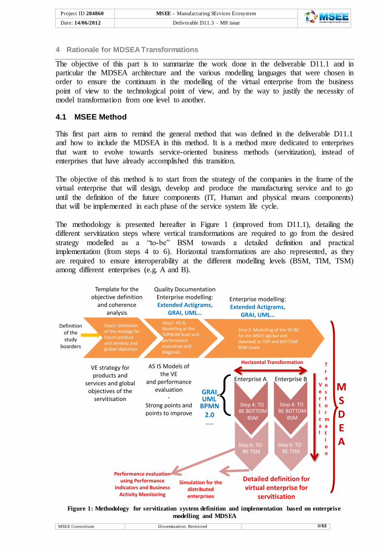
The methodology is presented hereafter in Figure 1 (improved from D11.1), detailing the different servitization steps where vertical transformations are required to go from the desired
strategy modelled as a “to-be” BSM towards a detailed definition and practical implementation (from steps 4 to 6). Horizontal transformations are also represented, as they
are required to ensure interoperability at the different modelling levels (BSM, TIM, TSM) among different enterprises (e.g. A and B).
Figure 1: Methodology for servitization system definition and implementation based on enterprise
modelling and MDSEA
Step 2
Step1: Definition of the strategy for future productand services and global objectives
Step 3: Modelling of the TO BEfor the MSEE (global and detailed) at TOP and BOTTOM BSM levels
Detailed definition forvirtual enterprise for
servitisation
Quality DocumentationEnterprise modelling: Extended Actigrams,
GRAI, UML…
AS IS Models ofthe VE
and performance evaluation
-Strong points and points to improve
GRAIUML
BPMN 2.0……
Template for the objective definition
and coherence analysis
Enterprise modelling: Extended Actigrams,
GRAI, UML…
VE strategy for products and
services and global objectives of the
servitisation
Performance evaluation using Performance
indicators and Business Activity Monitoring
Definition of the study
boarders
Step2: AS IS Modelling at the TOPBOM level and performance evaluation and diagnosis
MSDEA
Step 5: TO
Step 6: TO BE TSM
Step 4: TO BE BOTTOM
BSM
Simulation for thedistributed enterprises
Step 6: TO BE TSM
Step 4: TO BE BOTTOM
BSM
Enterprise A Enterprise BVertical
Transformation
Horizontal Transformation

Project ID 284860 MSEE – Manufacturing SErvices Ecosystem
e Date: 14/06/2012 Deliverable D11.3 – M8 issue
MSEE Consortium Dissemination: Restricted 9/53
The horizontal sequence initializes the study to reach the TO BE for the Service System,
while the vertical sequence allows to implement the MDSEA in order to determine the components of the Service System by domains.
The objective of this first step is to prepare the modelling of the Enterprise or the virtual enterprise by defining the strategy in term of servitization. This step follows the innovation
step that we have not indicated and which has determined the orientation to define the service. The objective of the second step is to perform the modelling of the existing enterprise or
virtual enterprise at the BSM level (AS IS model) and to determine the current performances. Based on the objectives of Servitization and also of enterprise running improvement, the third step aims at modelling the future Service System at top BSM level, i.e. at the global level.
Starting from the TO BE models at the TOP BSM (Business) level, the fourth step is very
important to ensure the coherence in the deployment of the models and to avoid non-necessary works. This step consists in selecting the part of the service system that will be supported by new ITs, Human/organization or Physical means that will be developed at the
lower levels. At the TIM level (fifth step), the previous models are refined using various modelling languages in order to represent more detailed concepts independently of the
technology. At TSM level (sixth step), the objective is to generate the components of Service System in various domains: IT, Organization/Human and Technical resources.
For a detailed presentation, please read deliverable D11.1.
4.2 Model Driven Service Engineering
Based on the above methodology principle, the MDSEA architecture was defined in order to transform the business requirements of the virtual enterprise in the detailed specifications of the future components that must be implemented to support the servitization process.
The MDSEA architecture is reminded in the figure below.
Figure 2: The Model Driven Service Engineering Architecture
In this architecture, several modelling levels are defined to have a progressive specification of
service system components.
Business Service Modelling (BSM): models at the global level. The models at the
BSM level must be independent to the future technologies that will be used for the
various resources.
Organisation
HumanDomain
Physical
meansDomain
IT
Domain
Business Services Models (BSM)
Technology Independent Models (TIM)
Technology Specific Models(TSM)
Services in virtual enterprises(IT Applications, Processes, Products,
Services, Organisation/Human, Physical
Means(machine, robots), etc…)
Generation of “components”
( IT_ Organisation/Human_Physical means
Project ID 284860 MSEE – Manufacturing SErvices Ecosystem
e Date: 14/06/2012 Deliverable D11.3 – M8 issue
MSEE Consortium Dissemination: Restricted 10/53
Technology Independent Modelling (TIM): models at a second level of abstraction
independent from the technology used to implement the system, detailed
specifications of the structure and functionalities of the service system but no
technological details, i.e. detailed specification of IT, Organisation/Human and
Physical means
Technology Specific Modelling (TSM): combines the specifications with details on
how the system uses a particular type of technology (such as for example IT platform,
Machine technology or specific person), modelling and specifications must provide
sufficient details to allow developing or buying software applications, components,
recruiting human operators / managers or establishing internal training plans, buying
and realizing machine devices, for supporting and delivering services in interaction
with customers.
The approach implies that the different levels should use dedicated service modelling languages that represent the system with the appropriate level of description in order to fulfil
the objectives of the modelling: first, to understand and analyse the systems; second, to design progressively, from the global view to the detailed one, the target systems while creating or
improving the service level provided by the virtual enterprise. Taking into account the technology, MDSEA models should integrate the requirements leading to the implementation of a solution in IT, organization or physical mean domain.
Thus, a methodology to support the transformation of the models between the different levels
of description will be useful. Technologies are discussed in section 4 and an approach for MSEE will be proposed in section 5, where interoperability among different enterprises of distinct domains is also a key issue. Supporting that transformations methodology, in the next
part, the choice of modelling languages will be presented for each level based on the core constructs that were selected for the modelling of product, related services and service
system.
4.2.1 Presentation and explanation of Selected Service Modelling Languages
Several modelling languages have been chosen at each MSDEA modelling level depending of
each modelling objective. Indeed, it was necessary to have a global conceptual model that guides the choice of the various modelling languages in order to ensure that the concepts modelled at each level are not redundant and that they are linked together in a coherent way
inside the same conceptual model.
MSEE project has chosen to use the GRAI model (Doumeingts & Ducq (2001)) to select the various modelling languages. Then, the various languages chosen for each level are the following:
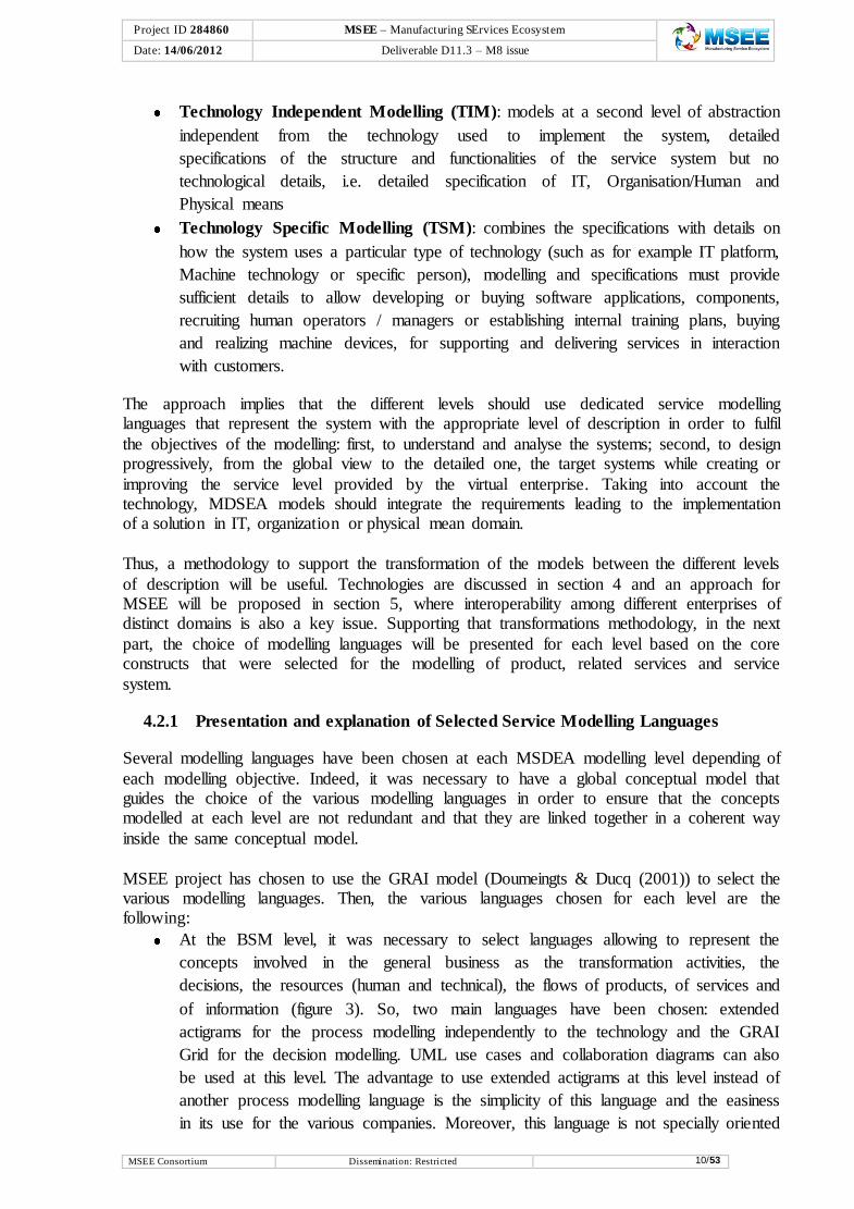
At the BSM level, it was necessary to select languages allowing to represent the
concepts involved in the general business as the transformation activities, the
decisions, the resources (human and technical), the flows of products, of services and
of information (figure 3). So, two main languages have been chosen: extended
actigrams for the process modelling independently to the technology and the GRAI
Grid for the decision modelling. UML use cases and collaboration diagrams can also
be used at this level. The advantage to use extended actigrams at this level instead of
another process modelling language is the simplicity of this language and the easiness
in its use for the various companies. Moreover, this language is not specially oriented

Project ID 284860 MSEE – Manufacturing SErvices Ecosystem
e Date: 14/06/2012 Deliverable D11.3 – M8 issue
MSEE Consortium Dissemination: Restricted 11/53
IT and then all kinds of resources are modelled at the same level. The cover by each
language of the expected core constructs at BSM level is shown in the Figure 3 below
which shows their complementarity.
Figure 3: The coverage of the BSM core constructs by the selected languages
At the TIM level, the modelling languages must allow a more detailed representation
of each concept and must be oriented towards IT or Human or Physical Means
modelling (figure 4). So, for the process modelling, BPMN 2.0 was chosen because
this language is more IT oriented which is also an objective at this modelling level.
Concerning decision modelling, the GRAI nets were chosen in order to have a precise
view of the decision processes and the various resources involved in these decisions.
The coverage by the first languages chosen at TIM level of the expected core
constructs at TIM level is shown in the Figure 4 below which shows their
complementarity.
Figure 4: The coverage of the TIM core constructs by the first selected languages
ResourceFunctionality
Stakeholder
DecisionPerformance
indicatorProductValue
provide
measured byrelated tohave
control
relate to
have concern
apply
Customer
consume
Partnercontribute
haveOrganization
Decision
structurelinked
to
applyService Process
have
apply
Extended Actigrams Star concepts
GRAI grid and nets and ECOGRAI
Resource
provide composed of
haveOrganization
is a
Enterprise applicationPhysical
meanHuman
Information
used by
is a is a
Organization
unit
responsible to
Service Process
BPMN 2.0
concepts
used by
Decisionsapply
UML
concepts
GRAI Nets
concepts

Project ID 284860 MSEE – Manufacturing SErvices Ecosystem
e Date: 14/06/2012 Deliverable D11.3 – M8 issue
MSEE Consortium Dissemination: Restricted 12/53
At the TSM level, WSDL or SoaML languages are proposed but no choice is decided
at this time, since the major focus of transformations addressed in the deliverable is
from BSM to TIM.
4.3 MDSEA Core and Reference Meta-models
In order to further detail each core construct at the BSM and TIM levels in order to facilitate a
relevant transformation, it could be necessary to use the templates as shown in the figure below (Figure 5). The idea is, to have a “zoom” view on the BSM and TIM core constructs
separating each MDSEA concern (e.g. zoom on service, process, decision, etc.). The templates of D11.1 originally give this detail but need to be here extended with the concepts that each language provides in addition (e.g. extended actigram has more details than the one
envisaged in the templates). Thus, the BSM/TIM/TSM meta-models are divided into:
Core Constructs – that identify the list of core concepts (and their relationships)
relevant to design the model of a Service System;
Reference Meta-models – extend each core construct, identifying the inherent list of
relevant sub-concepts (and their relationships) enabled by the relevant modelling
languages or tools. To be usable in the transformations, the former templates need to
be described as formal meta-models.
Figure 5: The detail of each core construct using associated template
Even if all the template constructs are not yet used in the transformation mechanisms presented hereafter, at least, information contained in some templates is. Further work is
expected in the upcoming WP1.1 deliverables.
ResourceFunctionality
Stakeholder
DecisionPerformance
indicatorProductValue
provide
measured byrelated tohave
control
relate to
have concern
apply
Customer
consume
Partnercontribute
haveOrganization
Decision
structurelinked
to
apply
Service Process
have
apply
Extended Actigrams Star concepts
GRAI grid and nets and ECOGRAI
Header
Construct label [‘Customer]
Identifier [Identifier of the customer instance]
Name [name of the customer instance]
Body
Categories [Worker, farmer, student,…]
Level of education [short textual description]
Gender and age [Short textual description]
Annual revenue range [Short textual description]
Targeted frequency of service use Short textual description]
Wish and requirement [Short textual description]
Constraint [Short textual description]
Relationships to other model elements
SERVICE [Identifier/name of Service concerned by the customer: described by Service template]
Other Relationships
RELATED TO MODEL LEVEL [Refer to BSM, TIM, TSM modeling level] : BSM
RELATED TO SLM PHASE [Refer to service lifecycle phases] : Requirement

Project ID 284860 MSEE – Manufacturing SErvices Ecosystem
e Date: 14/06/2012 Deliverable D11.3 – M8 issue
MSEE Consortium Dissemination: Restricted 13/53
In collaboration with WP1.5, regarding the design and the development of the SLMToolBox, and to ensure that the implementation of the MSEE software tools is mutually aligned with
the concepts defined by WP1.1, initially some templates (now designated as reference meta-models) have been updated (see Table 1 and Table 2). Nevertheless this work is only at the beginning and the analysis of further languages can lead to the extension of the reference
meta-models.
4.3.1 BSM
The following table 1 shows the main core concepts/constructs that are taken into account in the transformation of languages at BSM level. In the application case, some constructs are not taken into account for the core package, depending on the chosen source and target languages.
Table 1: Modification of BSM core constructs
Core Concepts Modification
product / functionality
The relation “product → functionality” is added in order to represent the functional decomposition of a product.
functionality The attribute “functionality” is renamed “description” for coherence
purpose.
resource The attribute “function” is renamed “role” for coherence purpose.
process The attribute “result” is renamed “output” for coherence purpose.
process The attribute « subprocess » is replaced by a recursive relation “is composed of”, so that a process instance knows its “sub processes” and
to which process it is attached. The graphical representation of a process is handled by the “extended
actigram star” modelling language whose main constructs are directly mapped with some BSM <<process>> reference meta-model attributes.
decision The following attributes are suppressed from the core constructs
package, because they are delegated to the reference meta-model (namely “GraiGrid” modelling language constructs), which are
referenced by the “decision” construct at the BSM level :
Horizon(referenced in [Grai].DecisionCenter→
[Grai].DecisionLevel.horizon)
Period (referenced in [Grai].DecisionCenter→
[Grai].DecisionLevel.period)
decision
structure
The following attributes are suppressed from the core constructs
package, because they are delegated to the reference meta-model (namely “GraiGrid” modelling language constructs), which are referenced by the “decision structure” construct at the BSM level :
Relationship (referenced in [Grai].GraiGrid→
[BSMCore].DecisionStructure]
Function (referenced in [Grai].GraiGrid→ [Grai].FunctionGrai)
Level (referenced in [Grai].GraiGrid→ [Grai].DecisionLevel)
Center (referenced in [Grai].GraiGrid→ [Grai].DecisionCenter)
The graphical representation of a decision structure is handled by the “Grai Grid” modelling language whose main constructs are mapped with

Project ID 284860 MSEE – Manufacturing SErvices Ecosystem
e Date: 14/06/2012 Deliverable D11.3 – M8 issue
MSEE Consortium Dissemination: Restricted 14/53
Core Concepts Modification
some BSM <<decision structure>> reference meta-model attributes.
component A core construct « component » is added, to structure the attribute
“components” of the “product” construct
decision/service The relation “decision → service” is deleted.
organization The attribute “description” is textual
decision / process
The relation “decision → process” is added. In order to represent the “control” of a decision over one or several processes.
Based on the BSM templates and the changes described above, the following Figure 6 represents the BSM core constructs meta-model. It is a package of abstract classes that, as explained before, can be extended to a reference meta-model with 1:1 realization relationships
with the language specific constructs (see Figure 7 and Figure 8).

Project ID 284860 MSEE – Manufacturing SErvices Ecosystem
Date: 14/06/2012 Deliverable D11.3 – M8 issue
MSEE Consortium Dissemination: Restricted 15/53
Figure 6: BSM Core Constructs Meta-model

Project ID 284860 MSEE – Manufacturing SErvices Ecosystem
Date: 14/06/2012 Deliverable D11.3 – M8 issue
MSEE Consortium Dissemination: Restricted 16/53
Figure 7: BSM Reference Meta-Model: core constructs extension with Grai Grid constructs
Figure 8: BSM Reference Meta-Model: core constructs extension with Extended Actigram Star constructs

Project ID 284860 MSEE – Manufacturing SErvices Ecosystem
e Date: 14/06/2012 Deliverable D11.3 – M8 issue
MSEE Consortium Dissemination: Restricted 17/53
4.3.2 TIM
The following table 2 shows the main core constructs that are taken into account in the transformation of languages at TIM level. Again, in the application case, some constructs are
not taken into account for the core package, depending on the chosen source and target languages.
Table 2: Modification of TIM core constructs
Core Concepts Modification
service The attributes « composition » and « decomposition » are replaced by a
recursive relation “is composed of”, so that a service instance knows its “sub services” ant to which service it is attached.
process The attribute « subprocess » is replaced by a recursive relation “is
composed of”, so that a process instance knows its “sub processes” ant to which process it is attached.
process The attribute “workflow” is a “textual description”.
The graphical representation of a process is handled by the “BPMN” modelling language whose main constructs will be mapped with some
TIM <<process>> reference meta-model attributes.
organizationUnit The attribute “member” is replaced by a relation “is part of” to “human” construct, so that an instance of “Organization unit” knows its human
members.
organizationUnit The cardinalities of the references to some constructs are modified from “0…1” to “0…*” :
Decision
Resource
Process
organization The attributes “description”, “responsibility” and “authorization” are a
textual descriptions
information The attribute “relationship” is a “textual description”.
The graphical representation of a its decompositions in the form of a UML class diagram is handled by the “UML Class” modelling language which main constructs will be mapped with some TIM << information
>> reference meta-model attributes
Based on the TIM templates and the changes described above, the following Figure 9
represents the TIM core constructs meta-model. As in the case of the BSM level, this is a package of abstract classes that can be extended to a reference meta-model with 1:1
realization relationships with the language specific constructs at the same level (see Figure 10).

Project ID 284860 MSEE – Manufacturing SErvices Ecosystem
Date: 14/06/2012 Deliverable D11.3 – M8 issue
MSEE Consortium Dissemination: Restricted 18/53
Figure 9: TIM Core Constructs Meta-model

Project ID 284860 MSEE – Manufacturing SErvices Ecosystem
Date: 14/06/2012 Deliverable D11.3 – M8 issue
MSEE Consortium Dissemination: Restricted 19/53
Figure 10: TIM Reference Meta-Model: core constructs extension with BPMN2.0 constructs
4.4 Tentative mapping from BSM level to TIM level
The following Table 3, below, shows the correspondence between the core constructs at the
BSM and TIM levels.
Table 3: Tentative BSM-TIM mapping
BSM TIM
Service Service
Customer -
Stakeholder -
Partner -
Product -
Functionality -
Resource
Resource.type = IT
Resource
EnterpriseApplication
Resource.type = physical mean PhysicalMean
Resource.type = human Human
- Information
Process Process
Decision -
Organization Organization
- Organization unit
Performance Indicators -
Value -
Project ID 284860 MSEE – Manufacturing SErvices Ecosystem
e Date: 14/06/2012 Deliverable D11.3 – M8 issue
MSEE Consortium Dissemination: Restricted 20/53
One can observe in the table that the mapping between BSM and TIM constructs and models
is only partial. There is at least nine constructs at BSM level which have no correspondence at the TIM level (Customer, Stakeholder, Partner, Product, Functionality, Decision, Decision
Structure, Performance Indicators, Value), thus they must be complemented with additional modelling at TIM level that take these constructs into account.
We can also observe that each BSM construct that has a correspondence at the TIM level, is completely mapped, so we can retrieve all their information at the TIM level.
Based on these work, it is now necessary to define the transformation mechanisms. So, after a presentation of the state of the art in the domain of transformation methods in the next
section, the proposed mechanisms will be presented in the following.

Project ID 284860 MSEE – Manufacturing SErvices Ecosystem
e Date: 14/06/2012 Deliverable D11.3 – M8 issue
MSEE Consortium Dissemination: Restricted 21/53
5 Literature Review in Model Transformation
Model transformation is not a new concept. It has been broadly used in Model Driven Development/Engineering (MDD/MDE) methods where models and their roles in the development process should change from contemplative (e.g., used for documentation) to
productive, thus envisaging transformations from high-level business models focusing on goals, roles and responsibilities down to detailed use-case and scenario models for business
execution. Model Driven Interoperability (MDI) is another recognized model-driven method envisaging model transformations to solve interoperability problems between enterprises not only at the application and software systems level, but also at the Enterprise Modelling level.
Therefore, before proposing anything completely new or radically different for MDSEA,
MSEE would benefit from a review of relevant works in model transformation, to identify a baseline for proposing an efficient model transformations framework and architecture for service systems.
Among the several realizations of MDD, e.g., Agile Model Driven Development (Ambler
2008), Domain-oriented Programming (Thomas & Barry 2003), Microsoft’s Software Factories (Greenfield et al. 2004) and Model Driven Architecture (MDA) (OMG 2003), MDA is perhaps the most prevalent at the moment. Thus, the review is focused in MDA related
implementations, namely on transformations among the three different MDA abstraction levels, Computation Independent Models (CIM), Platform Independent Models (PIM), and
Platform Specific Models (PSM), which are conceptually related to the MDSEA BSM, TIM, and TSM levels.
5.1 Integrated Transformation-based Approaches towards Interoperability
The approach "Model Driven Interoperability" (MDI) (figure 11) consists in considering interoperability problems from enterprise models level instead of only at the coding step.
Figure 11: MDI method reference framework
These works realized in the Task Group 2 (TG2) of INTEROP-NoE state at defining an approach inspired from OMG MDA. The goal is to tackle the interoperability problem at each
abstraction level defined in MDA and to use models transformations techniques to link vertically the different levels of abstraction or horizontally to ensure each models of the level
interoperability. The general framework of the approach proposed in TG2 is presented in

Project ID 284860 MSEE – Manufacturing SErvices Ecosystem
e Date: 14/06/2012 Deliverable D11.3 – M8 issue
MSEE Consortium Dissemination: Restricted 22/53
Figure 11. The main goal of this methodology, based on model transformation, is to allow a
complete flow from expressing requirements to coding of a solution and also a greater flexibility thanks to the automation of these transformations.
In a similar line of work, Elvesæter et al. (2005), in the course of project Athena (Athena 2005), have specified an integrated framework for interoperability developed from a MDD
point of view. They proposed three reference architectures for integration at conceptual, technical, and applicative levels. As illustrated in Figure 12, the reference architecture for
conceptual integration differentiates vertical integration from horizontal integration:
Vertical, envisages integration among the CIM, PIM and PSM levels using
specification and generalization model transformations;
Horizontal, envisages integration between the same levels of different enterprise
systems.
Figure 12: Reference architecture for conceptual integration (Elvesæter et al. 2005)
The models at the various levels may be semantically annotated using reference ontologies, which help to achieve mutual understanding on all levels. They use this reference model to
address model interoperability, where meta-models and ontologies are used to define model transformations and model mappings between the different views of an enterprise system.
At PSM level of the enterprises systems, simulation can be used to test and validate properties and follow indicators in order to check the conformity regarding concepts that were modelled
at the CIM level. One common barrier to overpass, while implementing the solutions, is the communication with the outside. Interoperability is desired to overcome this barrier.
Distributed simulation tries to address the problem of heterogeneity of the models and platform by developing common bus to exchange the information (Wenguang Wang et al.
2009). The distributed simulation supports the format of data exchanged and the dynamic consideration. It does not solve the understanding of data exchanged that is left to a local
interpretation and use.

Project ID 284860 MSEE – Manufacturing SErvices Ecosystem
e Date: 14/06/2012 Deliverable D11.3 – M8 issue
MSEE Consortium Dissemination: Restricted 23/53
5.1.1 Levels of Interoperability
To differentiate integration, interoperability, where execution and simulation are important, or composability, where modelling is the primary goal, Tolk & Muguira (2003) proposed a set of
levels to deal with conceptual integration issues beyond technical interoperability, i.e. Levels of Conceptual Interoperability Model (LCIM). LCIM divides conceptual interoperability into layers (see Figure 13) to cope the need for a suitable framework to capture the artefacts
needed for simulation interoperation.
Figure 13: The Levels of Conceptual Interoperability Model (Wenguang Wang et al. 2009)
LCIM is becoming more and more mature and is gaining recognition, therefore it has
becoming an application with a wide potential. Besides the simulation interoperability community it is being used by scientists of multiple disciplines to deal with problems in their
communities (Tolk 2006), e.g. system biologists and ontology researchers. Another approach proposed a 3 dimensional description of the interoperability. These levels
are based on ATHENA Architecture (Athena IP 2006). This representation takes into consideration the 3 admitted approaches to develop interoperability as illustrated in Figure 14.
In particular they describe the historical approaches to solve interoperability:
Integrated approach: there exists a common format for all models. This format must
be as detail as models. The common format is not necessarily a standard but must be
agreed by all parties to elaborate models and build systems.
Unified approach: there exists a common format but only at a meta-level. This meta-
model is not an executable entity as it is in the integrated approach, but provides a
mean for semantic equivalence to allow mapping between models.
Federated approach: there is no common format. To establish interoperability,
parties must accommodate on the fly. Using federated approach implies that no
partner imposes his or her models, languages and methods of work.
Today, most of the approaches developed are unified ones such as for example in the domain
of enterprise modelling, we can mention UEML (Unified Enterprise Modelling Language) and PSL (Process Specification Language) which aim at supporting the interoperability between enterprise models and tools. Using the federated approach to develop Enterprise
Interoperability is most challenging and few activities have been performed in this direction

Project ID 284860 MSEE – Manufacturing SErvices Ecosystem
e Date: 14/06/2012 Deliverable D11.3 – M8 issue
MSEE Consortium Dissemination: Restricted 24/53
since it aims to develop full interoperability and is particularly suitable for an inter-
organizational environment (such as networked enterprises, virtual enterprises, etc.).
Figure 14: Framework for enterprise interoperability
In the Enterprise Interoperability roadmap published by the European Commission
(Enterprise Interoperability Cluster 2008), developing federated approach for interoperability is considered as one of the research challenges for the years to come. It considers
interoperability problems from enterprise models level instead of only at the coding step.
5.1.2 Model Transformation and Simulation
Following LCIM, in particular at the level of implementation, Wenguang Wang et al. (2009)
proposes the use of distributed simulation standards. These standards are based on sound synchronization algorithms proposed in the late 70s. One, for instance, the High-level
Architecture (HLA) was used at the beginning in military simulation for a purpose of reusing existing simulation platforms. It is discussed to be a medium to facilitate the data exchange between heterogeneous modelling formalisms and simulation architectures.
This solution provides no semantic interpretation of the data exchanged and it is simply
employed to handle data regarding format and temporal causality aspects (Zacharewicz et al. 2009). Figure 15 is presenting the central Run Time Infrastructure (RTI) that orchestrates the HLA simulation by routing the messages between the distributed components. The
“federates” extends the local information system (code) with a local RTI component used to decode the information coming from the network according to the local meta-models
Figure 15: HLA Distributed Simulation Platform
5.2 Specific Implementations on CIM, PIM, or PSM Transformations
Besides integrated architectures and approaches that provide an overall view on existing technology, the reuse of specific MDA driven implementations (or parts of) could help in the
design and implementation of the MDSEA transformations framework and architecture,
Project ID 284860 MSEE – Manufacturing SErvices Ecosystem
e Date: 14/06/2012 Deliverable D11.3 – M8 issue
MSEE Consortium Dissemination: Restricted 25/53
especially when modelling languages are the same as the envisaged in section 4.2.1
“Presentation and explanation of Selected Service Modelling Languages”.
5.2.1 CIM – PIM Transformations in MDI
The analysis of approaches at this level of transformations shows that the problem of transforming CIM models into PIM models is not still solved, since all of them produce this transformation manually or almost manually (Grangel, Correa, et al. 2007). From the reduced
information found on this type of transformations, the most relevant are associated to the MDI framework presented before.
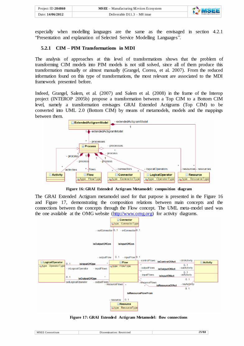
Indeed, Grangel, Salem, et al. (2007) and Salem et al. (2008) in the frame of the Interop project (INTEROP 2005b) propose a transformation between a Top CIM to a Bottom CIM
level, namely a transformation envisages GRAI Extended Actigrams (Top CIM) to be converted into UML 2.0 (Bottom CIM) by means of metamodels, models and the mappings
between them.
Figure 16: GRAI Extended Actigram Metamodel: composition diagram
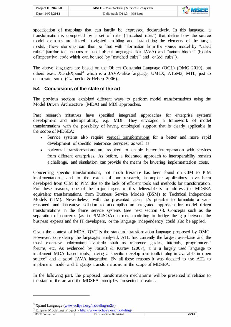
The GRAI Extended Actigram metamodel used for that purpose is presented in the Figure 16
and Figure 17, demonstrating the composition relations between main concepts and the connections between the concepts through the Flow concept. The UML meta-model used was the one available at the OMG website (http://www.omg.org) for activity diagrams.
Figure 17: GRAI Extended Actigram Metamodel: flow connections

Project ID 284860 MSEE – Manufacturing SErvices Ecosystem
e Date: 14/06/2012 Deliverable D11.3 – M8 issue
MSEE Consortium Dissemination: Restricted 26/53
According to the work presented, to perform the desired objective it is necessary to build the
mappings between the constructs and relations of the GRAI Extended Actigram Metamodel and the UML Activity Metamodel. The proposed mapping is shown in Figure 18. These
correspondences must be defined from both syntactic and semantic point of view. From syntactic point of view, the mapping must ensure the consistency of the produced target model. For example, GRAI Flow can be mapped on UML Object or Control Flow depending
on its ends: if one of its extremities is connected to a GRAI connector or Resource, then the flow is mapped onto an UML Object Flow, otherwise it is mapped onto a UML Control Flow.
Figure 18: GRAI Extended Actigram to UML Activity Diagram Mapping
In order to demonstrate the feasibility of these model transformations from GRAI to UML,
Atlas Transformation Language (ATL) and its associated transformation tool were used (Eclipse foundation 2011), whose result produced a XMI-serialised UML file which could be imported into a UML Tool like IBM Rational Software Modeler.
5.2.2 PIM – PSM Transformations in MDI
Much more common than CIM to PIM transformations, this level of vertical transformations
accounts already with some advance transformation tools, such as AndroMDA1, which makes use of UML to enrich models and generate code.
An interesting work has been developed by Benguria et al. (2006) addressing the development of a SOA modelling language able to decouple the logical solution from the technical
implementation. The solution provides a platform independent (PIM) meta-model for SOA and a set of transformations that link the meta-model with specific platforms following the Model Driven Architecture (MDA) approach. The authors have identified and separated four
aspects where specific concerns should be addressed, i.e., information, service, process and QoS. Consequently they created a meta-model for each of them to be part of a principal meta-
model, the PIM4SOA meta-model, which should:
bridge the gap between the business analysts and the IT developers and support
mapping and alignment between enterprise and IT models;
define a platform neutral abstraction that can be used to integrate and define mappings
to web service architecture, business process, agent and peer-to-peer platforms.
1 AndroMDA – www.andromda.org

Project ID 284860 MSEE – Manufacturing SErvices Ecosystem
e Date: 14/06/2012 Deliverable D11.3 – M8 issue
MSEE Consortium Dissemination: Restricted 27/53
Once the PIM4SOA has been defined, platform specific (PSM) artefact can be derived from it
(see Figure 19).
Figure 19: PIM and PSM levels (Benguria et al. 2006)
For the implementation of the meta-model they used the EMF2 tooling available in Eclipse, which allows them to define Ecore meta-models using the EMOF (Essential Meta Object
Facility) meta-meta-model. They included another component to the solution to visualize and to create the PIM4SOA models, the UML profiling mechanism.
5.2.3 Horizontal transformations (CIM-CIM, PIM-PIM, or PSM-PSM) in MDI
Horizontal transformations are, as envisaged in the integrated approaches previously presented in section 3.1, more focused on promoting interoperability among different
enterprise systems. Implementations at this level of integration demonstrate a way to integrate two companies that use different models and want to exchange data between them, e.g. Figure 20. By specifying, at CIM, PIM or PSM models, a mapping of concepts, automatic data
transformation is obtained (the same rationale is valid of meta-model mappings to model transformations, etc.). In the case presented, the fields in table “Contact” from Enterprise “A”
are mapped to table “PersonalInformation” in Enterprise “B”. Although, interoperability between the enterprises “A” and “B” is achieved, some information are lost in this specific case because the field “email” cannot be mapped to any correspondent in Enterprise “B” data
model. This can cause a potential problem in the reverse transformation.
Figure 20: Horizontal transformation example
Some authors such as Lubell et al. (2004), believe that integration of different modelling
languages already would solve a number of problems, namely it would enable industry
2 Eclipse Modeling Framework. 2005. http://www.eclipse.org/emf

Project ID 284860 MSEE – Manufacturing SErvices Ecosystem
e Date: 14/06/2012 Deliverable D11.3 – M8 issue
MSEE Consortium Dissemination: Restricted 28/53
validated models to become completely independent of the implementation tools. In the
example they address, implementation of data exchange standards (e.g. STEP) would benefit if the standardized models (e.g. product data standards) could become available in
technologies such as UML or XML. Continuing a similar idea, Agostinho et al. (2010) proposed a framework to enhance
interoperability in complex business networks, where business and information model integration is adapted to the companies’ needs, i.e. not specific to a particular technology. In
their approach, organizations require mechanisms capable of abstracting the model from the technology in which it is described. If that would be the case, more organizations could enlarge their business networks without having to make huge investments on specialized
personal and tools to handle technologies they are not aware. They propose a meta-model profile to enable to map any organization’s information model (in any specific format), to a
common base where mappings would be defined completely isolated from their language constraints (Figure 21).
Figure 21: Meta-Model for Language Independent Transformations (Agostinho et al. 2010)
5.3 Transformation Languages
A number of transformation languages provide the support for automatic model transformation execution in the frame of MDD/MDI, e.g. ATL and the QVT (Eclipse foundation 2011; OMG 2008).
QVT is a hybrid declarative and imperative transformation language that defines a standard
way to transform source models into target models, which is sustained by the four levels of OMG’s meta-modelling architecture. It also supports bidirectional model-to-model (horizontal) transformations conforming to any MOF 2.0 meta-model. This means that model
to text, whatever the text is (XML, Code, etc.), or vice-versa, is simply not supported.
ATL, the Atlas Transformation Language, is the ATLAS INRIA & LINA research group's answer to the OMG MOF/QVT RFP. It is not so rigid and enables association with other methods to accomplish that. The main difference between them is that it can only be used to
do unidirectional syntactic and semantic translation. The preferred style of transformation writing is the declarative one: it enables to simply express mappings between the source and
target model elements. However, ATL also provides imperative constructs in order to ease the
Project ID 284860 MSEE – Manufacturing SErvices Ecosystem
e Date: 14/06/2012 Deliverable D11.3 – M8 issue
MSEE Consortium Dissemination: Restricted 29/53
specification of mappings that can hardly be expressed declaratively. In this language, a
transformation is composed by a set of rules (“matched rules”) that define how the source model elements are linked, navigated enabling and instantiating the elements of the target
model. These elements can then be filled with information from the source model by “called rules” (similar to functions in usual object languages like JAVA) and “action blocks” (blocks of imperative code which can be used by “matched rules” and “called rules”).
The above languages are based on the Object Constraint Language (OCL) (OMG 2010), but
others exist: Xtend/Xpand3 which is a JAVA-alike language, UMLX, AToM3, MTL, just to enumerate some (Czarnecki & Helsen 2006)..
5.4 Conclusions of the state of the art
The previous sections exhibited different ways to perform model transformations using the Model Driven Architecture (MDA) and MDI approaches.
Past research initiatives have specified integrated approaches for enterprise systems development and interoperability, e.g. MDI. They envisaged a framework of model
transformations with the possibility of having ontological support that is clearly applicable in the scope of MDSEA:
Service systems also require vertical transformations for a better and more rapid
development of specific enterprise services; as well as
horizontal transformations are required to enable better interoperation with services
from different enterprises. As before, a federated approach to interoperability remains
a challenge, and simulation can provide the means for lowering implementation costs.
Concerning specific transformations, not much literature has been found on CIM to PIM implementations, and to the extent of our research, incomplete applications have been
developed from CIM to PIM due to the lack of efficient tools and methods for transformation. For these reasons, one of the major targets of this deliverable is to address the MDSEA
equivalent transformations, from Business Service Models (BSM) to Technical Independent Models (TIM). Nevertheless, with the presented cases it’s possible to formulate a well-reasoned and innovative solution to accomplish an integrated approach for model driven
transformations in the frame service systems (see next section 6). Concepts such as the separation of concerns (as in PIM4SOA) in meta-modelling to bridge the gap between the
business experts and the IT developers, or the language independency could also be applied. Given the context of MDA, QVT is the standard transformation language proposed by OMG.
However, considering the languages analysed, ATL has currently the largest user-base and the most extensive information available such as reference guides, tutorials, programmers’
forums, etc. As evidenced by Jouault & Kurtev (2007), it is a largely used language to implement MDA based tools, having a specific development toolkit plug-in available in open source4 and a good JAVA integration. By all these reasons it was decided to use ATL to
implement model and language transformations in the scope of MDSEA.
In the following part, the proposed transformation mechanisms will be presented in relation to the state of the art and the MDSEA principles presented hereafter.
3 Xpand Language (www.eclipse.org/modeling/m2t/)
4 Eclipse Modelling Project - http://www.eclipse.org/modeling/
Project ID 284860 MSEE – Manufacturing SErvices Ecosystem
e Date: 14/06/2012 Deliverable D11.3 – M8 issue
MSEE Consortium Dissemination: Restricted 30/53
6 Conceptual Solution: Model-Driven Transformations Framework
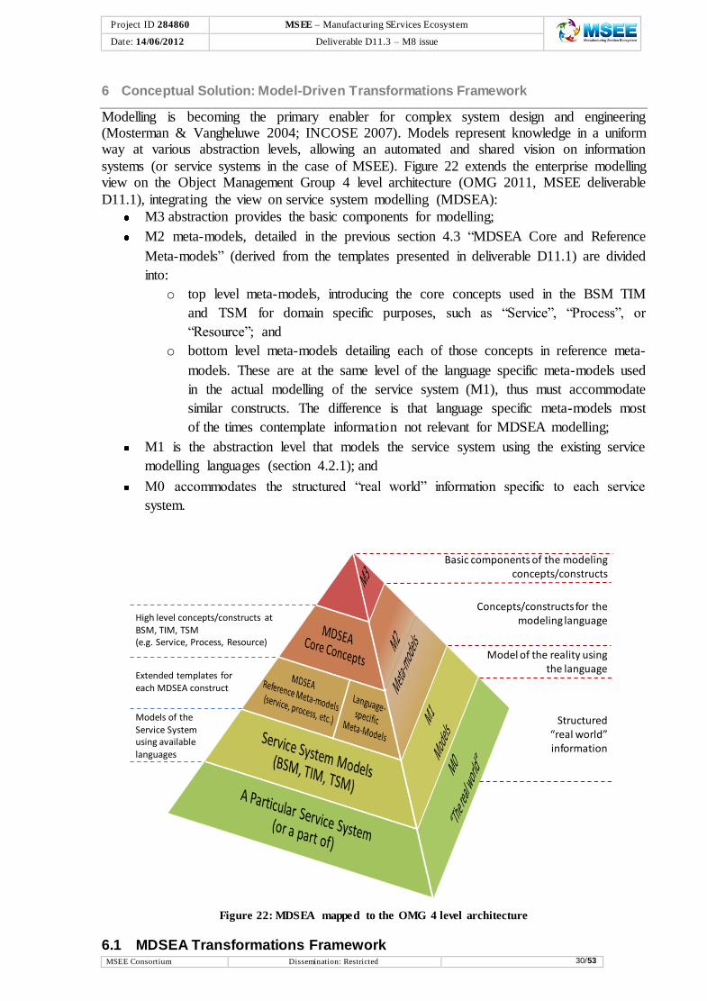
Modelling is becoming the primary enabler for complex system design and engineering (Mosterman & Vangheluwe 2004; INCOSE 2007). Models represent knowledge in a uniform way at various abstraction levels, allowing an automated and shared vision on information
systems (or service systems in the case of MSEE). Figure 22 extends the enterprise modelling view on the Object Management Group 4 level architecture (OMG 2011, MSEE deliverable
D11.1), integrating the view on service system modelling (MDSEA):
M3 abstraction provides the basic components for modelling;
M2 meta-models, detailed in the previous section 4.3 “MDSEA Core and Reference
Meta-models” (derived from the templates presented in deliverable D11.1) are divided
into:
o top level meta-models, introducing the core concepts used in the BSM TIM
and TSM for domain specific purposes, such as “Service”, “Process”, or
“Resource”; and
o bottom level meta-models detailing each of those concepts in reference meta-
models. These are at the same level of the language specific meta-models used
in the actual modelling of the service system (M1), thus must accommodate
similar constructs. The difference is that language specific meta-models most
of the times contemplate information not relevant for MDSEA modelling;
M1 is the abstraction level that models the service system using the existing service
modelling languages (section 4.2.1); and
M0 accommodates the structured “real world” information specific to each service
system.
Figure 22: MDSEA mapped to the OMG 4 level architecture
6.1 MDSEA Transformations Framework
Basic components of the modeling concepts/constructs
Concepts/constructs for the modeling language
Model of the reality using the language
Structured “real world” information
High level concepts/constructs at BSM, TIM, TSM (e.g. Service, Process, Resource)
Extended templates for each MDSEA construct
Models of the Service System using available languages

Project ID 284860 MSEE – Manufacturing SErvices Ecosystem
e Date: 14/06/2012 Deliverable D11.3 – M8 issue
MSEE Consortium Dissemination: Restricted 31/53
Following this integrated vision of MDSEA and OMG, as in MDA/MDI (Model Driven
Architecture/ Model Driven Interoperability) (MDA, 2008; MDI, 2010), MDSEA unifies every step of the Service System development, separating the functional specifications from
the implementation details related to a specific platform. It enables to model the Service System from its genesis, starting from a BSM of the system’s business functionality and requirements, through TIM and TSM, to generate code. This way, and as explained before,
part the MDSEA method’s objective is to start at the highest level (strategy of the companies) and derive solutions from successive transformations, instead of solving interoperability only
at the code level. However, each business ecosystem is characterized by a number of different enterprises with
several kinds of models and modelling technologies/languages. Therefore, the MSDEA method and transformations framework needs to be flexible to incorporate and address
existing models, enabling the development and extension of Service Systems. This may lead to the definition of multiple peer-to-peer integrations at any MSDEA level (BSM, TIM, TSM) to share models and data with business partners.
Therefore, MDSEA transformations approach applies the distinction between vertical and
horizontal transformations, providing interoperability and portability characterized by horizontal transformations among different service systems, at the same degree of relevance as the traceability features of vertical transformations, linking requirements, design, analysis,
and testing models of the several MDSEA abstraction levels. In this context, the MDSEA transformations are specified according to parameters defined along three axes (see Figure
23):
Axis 1 - Modelling levels, defined according to the reference architecture
categorization proposed by OMG (OMG 2011b) (Figure 22), which envisages that real world data is modelled using four levels that go for data itself (M0) to the meta-meta-model (M3). At the level M1, service models are described using the modelling
languages concepts and constructs defined at level M2. More detailed information on the OMG architecture can be found at MSEE deliverable D11.1.
Axis 2 - MDSEA levels, which, being inspired on the MDA/MDI enables Service
System modelling around three abstraction levels. As summarized in section 4.2, the Business Service Modelling (BSM) level is used for the business information, the
Technical Independent Modelling (TIM) level for the technical components of the Service System without taking in account the technology that will be used, and the
Technical Specific Modelling (TSM) level for the technical model of the various domains components, supporting their specific realization.
Axis 3- Ecosystem integration, which, starting from a minimum of two systems
represents the P2P integration among the multitude of systems part of the enterprise service ecosystem. Instead of defining direct transformations among the several
enterprise and modelling language specific models, MDSEA envisages that transformation data can go through MDSEA reference formats (derived from the
MSEE deliverable D11.1 templates), separating concerns to a neutral format, where the mappings are defined easier.

Project ID 284860 MSEE – Manufacturing SErvices Ecosystem
e Date: 14/06/2012 Deliverable D11.3 – M8 issue
MSEE Consortium Dissemination: Restricted 32/53
Figure 23: MDSEA Transformations Framework
Only with models correctly specified along the four levels of the first axis, transformations
can be defined at the second (vertical transformations) and the third (horizontal transformations), as detailed next.
6.1.1 Vertical transformations
Following the objectives of MDSEA, after having the initial specifications represented
globally from a business user’s point of view at the BSM level, transformations to the lower and more specific levels (TIM and TSM) along axis 2 are considered to be vertical
transformations (see Figure 23). They imply a change on the abstraction level of the resulting model, e.g. going from BSM to TIM implies a specialization transformation.
Based on the BSM models, the service system will be decomposed and complemented in the various components domains (IT, Organization/Human and Physical Means), and later
complemented with technology specific details, according to the model driven service-engineering paradigm (MSEE deliverable D11.1). The amount of generated code at the end of the vertical transformations process depends on both the code generator and also the level of
detail represented in the TSMs (i.e. how well the models capture the details of the physical platform). Ideally, only small portions of missing code should have to be added by the human
developer in order to ensure that the generated code and auxiliary files are ready for compilation, linking and deployment.
Mo
deli
ng
Levels
M3“meta-meta
model”
Ecosystem
BS
M
TIM
TS
M
M2“meta-model”
M1“model”
Service System A Service System B
M0“the real world”
MDSEA Horizontal Transf.

Project ID 284860 MSEE – Manufacturing SErvices Ecosystem
e Date: 14/06/2012 Deliverable D11.3 – M8 issue
MSEE Consortium Dissemination: Restricted 33/53
The MDSEA transformation framework proposes to improve vertical transformations
automation and traceability with knowledge enhancing methodologies, as described in section 6.3 “Knowledge Support to Mappings and Transformations”. The reverse vertical
transformation (bottom-up, i.e. generalization more abstract models) is not considered in the scope of MSEE.
6.1.2 Horizontal transformations
In both transformation types, the level of modelling abstraction in axis 1 remains unchanged.
Both source and target models must be an instance of well-defined meta-models, enabling experts to specify mappings that translate any data from one format to the other.
However, horizontal transformations, assure an effective exchange/sharing of information among different service systems, thus the level of detail of the both source and target models
should be similar, and the mapping process more exhaustive. Indeed, when performing this type of transformation an explicit or an implicit mapping of the meta-model has to be performed. Due to that, greater interoperability benefits but also harder complications are
expected in horizontal transformations mapping process (Agostinho et al. 2010).
Including methods for language translation, refactoring of individual models, or even merging different models, this type of transformations occur along axis 3 (ecosystem integration), thus leading to solutions for interoperability problems at the same MDSEA level, either BSM,
TIM, or TSM (axis 2).
As in the case of vertical transformations, the MDSEA transformation framework proposes to improve automation and traceability with knowledge enhancing methodologies, as described in section 6.3 “Knowledge Support to Mappings and Transformations”.
6.1.2.1 HLA to Support Models Horizontal Interoperability
To reduce the implementation cost of some horizontal transformations the use of distributed
simulation and HLA can be envisaged. As enounced in previous section, this new interoperability concept of horizontal interoperability needs to be tackled at run time. Based on the experience in HLA, it can be proposed an innovative implementation of Enterprise
Interoperability Federation (Zacharewicz et al. 2009).
An HLA “Interoperability” component layer can be added to models of enterprise either they are standardized models, ad hoc developed or either vendor solutions. The idea is to add a component to code and decode information exchanged with the original IS, this component is
considered as black box and no modification is realized on it. We present in detail in this section the components required for this global distributed platform.
The simulation can be also used to validate desired properties and behaviour of the platform regarding concepts specified at the BSM level.
6.2 Transformations Architecture
Before describing the transformations architecture in detail, it is important to recall the first
axis of the framework, namely the relationship between the concepts of model and meta-model. A model is a definition of some slice of reality, which is being observed and interpreted. Models can represent different aspects of one reality, derive from different
natures or be created using various languages, paradigms, concepts and formalism levels

Project ID 284860 MSEE – Manufacturing SErvices Ecosystem
e Date: 14/06/2012 Deliverable D11.3 – M8 issue
MSEE Consortium Dissemination: Restricted 34/53
(INTEROP 2005a). As followed by the OMG (OMG 2011b) reference architecture for
modelling, models must be written in well defined modelling languages, whose descriptions are also models (more abstract, and designated as meta-models), specifying constructs and
relationships used in a given language. This abstraction exercise could go onwards indefinitely from reality to model, meta-model, meta-meta model, meta-meta-meta model, etc.
Therefore, when performing a model transformation, one is converting instances of a source
model (Model A) to instances of another model, the target (Model B), and an explicit or an implicit mapping at the same meta-modelling level has to be performed. Thus, as depicted in the generic transformations architecture of Figure 24, the idea is that when performing a
transformation “τ(A,B)” at a certain level “i”, this transformation has (implicitly or explicitly) to be designed by taking into account mappings “θ(A,B)” at level “i+1”. Once the “i+1” level
mapping is complete, executable languages (e.g. ATL5 and QVT6) can be used to implement the transformation itself, either vertically (along axis 2) or horizontally (along axis 3).
Figure 24: Generic Transformations Architecture - adapted from MDA Guide (OMG 2003)
Nevertheless, simple type mappings are generally insufficient to specify a complete transformation (Truyen 2006). Following the works presented in section 4, additional
knowledge is frequently required to complement the mapping, specifying that certain concepts in the source model must be annotated (marked) in a specific way in order to produce the desired output in the target model. Sometimes, this extra information cannot be
determined from the source model itself, and it might need to use knowledge from external models, e.g. ontologies. For these reasons, the generic transformations architecture adopted by
MDSEA (Figure 24) is complemented with a “knowledge” box on top of the meta-model mappings. This concept is further detailed, considering the requirements of vertical and horizontal transformations, in section 6.3 “Knowledge Support to Mappings and
Transformations”.
6.2.1 Service Language Independence (Language Agnostic)
Transformations following the traditional MDA/MDI paradigm are usually specific to the modelling language (e.g. Extended Actigram, BPMN, UML, etc.), which reduces the
5 ATL – Atlas Transformation Language (www.eclipse.org/m2m/atl/)
6 QVT – Query View Transformation (www.omg.org/spec/QVT/)
Model A Model B
Transformationτ(A,B)
Mappingθ(A,B)
Mi
Source Target
Source MetamodelMi+1
Target Metamodel
Conforms toConforms to
Realizes
Knowledge

Project ID 284860 MSEE – Manufacturing SErvices Ecosystem
e Date: 14/06/2012 Deliverable D11.3 – M8 issue
MSEE Consortium Dissemination: Restricted 35/53
efficiency of any transformation framework used on a large enterprise ecosystem. As
analysed in the literature review, in fact, different languages might enable to describe the same objects but with different constructs and detail levels (e.g. properties, constraints, etc.),
thus mappings that could be reusable, are specific and dependent on the language constraints. This is the traditional way of managing model transformations, but MSEE wants to move further ahead, levelling all languages at the MDSEA integrated modelling format, across the
various levels of axis2 abstractions, to support service system design and implementation.
In this context, to (i) bridge the gap between the business experts and the IT developers, and (ii) enhance service system development, transformations generalization, and reusability; while supporting mapping and alignment between enterprise and service models,
organizations require mechanisms capable of abstracting the model from the technology (language) in which it is described (see Figure 25). This happens because enterprises benefit
from detaching technology details, and focus on the fundamental concepts for managing and planning their service system behaviour, i.e. defining the mappings using the extended generic MDSE reference meta-models at BSM, TIM, and TSM (more detail on section 4
“Rationale for MDSEA Transformations”). Bringing business experts, designers and system architects to the model, to collaboratively define mappings, rather than bringing the model to
them is the best way to work. If that would be the case, enterprises using the MDSEA transformations framework would
have a lightweight, portable and compatible interface with existing solutions, without having to make huge investments on specialized personnel and tools to manage technologies they are
not aware. After defining the mappings at a language agnostic format (acting as the ecosystem standard), model specializations would enable outputs to any desired technology (language).
Figure 25: Language independence derived from the MDSEA reference meta-models
For example, from a horizontal transformations point of view, with the language obstacle out
of the way, ecosystem’s enterprises will become capable of establishing gradual P2P mappings on a need-to-serve basis, independently from the language each service system
model is described on. This means that organizations continue to use their legacy systems and technologies of election, without needing to adjust to each enterprise they want to collaborate. Instead, the approach used in the transformations framework resides on companies applying
an interface, i.e. a meta-model profile achieved from the extended MDSEA meta-models and acting as a modelling language translator for all service system models. Hence, each
enterprise does not need to know how to relate their models to the modelling language specificities of the other companies’ models - they just have to focus on how to correctly link themselves to the interface and generate harmonizable models.
MDSEA Transformations Framework
BSM/TIM/TSM Template Meta-
Models
BSM/TIM/TSM Template Meta-
Models
MDSEA Reference Meta-Models
Language 1 constructs
Language 2 constructs
Language 3 constructs
Language n constructs
...
Language 1 constructs
Language 2 constructs
Language 3 constructs
Language n constructs
...
Language Abstraction
Language Specialization

Project ID 284860 MSEE – Manufacturing SErvices Ecosystem
e Date: 14/06/2012 Deliverable D11.3 – M8 issue
MSEE Consortium Dissemination: Restricted 36/53
6.2.2 Extended Architecture
Considering the service language independence, the generic transformations architecture presented in the previous Figure 24 is complemented to the MDSEA extended
transformations architecture of Figure 26. Following the same mapping-transformation principles, the source model is transformed to a format according the language agnostic MDSEA reference meta-models (conformant to the same meta-meta-model), among which
vertical and horizontal transformations occur to generate the target output, which is again language specific.
As before, additional knowledge may be required at any mapping/transformation step (detailed in section 6.3 “Knowledge Support to Mappings and Transformations”).
Figure 26: MDSEA Extended Transformations Architecture
6.3 Knowledge Support to Mappings and Transformations
Transformations, are traditionally static processes that once defined can be repeated any number of times achieving the same results. The major difficulty is defining them while supporting ecosystems dynamicity, joining the efforts of business and technical specialists at
reduced costs. Due to the constant knowledge change caused by the dynamics of the global market, service systems are not static and the mappings that connect them should be prepared
to respond to the environment dynamics, which is in a constant update. To support this dynamicity and improve the syntactical/structural alignment, the transformations architecture proposed is provided with knowledge enhancing methodologies and traceability features that
improve automation and re-engineering.
Semantics are recognized as an important area for models alignment identified as one of the levels of interoperability to consider within an enterprise (Athena IP 2006). Wenguang Wang et al. (2009) place semantic interoperability in the middle of the LCIM (levels of conceptual
interoperability model) scale towards a seamless conceptual interoperability, where more than an agreement between all systems on a set of terms, companies need a shared understanding
of the system’s conceptual models. However, a general observation shows that in traditional MDA/MDI transformations this
semantic knowledge is often not exploited to improve integration and interoperation
Model A Model B
Transformationτ(A,B)
Mappingθ(A,B)
Knowledge
Mi
Source Target
Source Metamodel
Mi+1 Target Metamodel
Conforms to Conforms toRealizes
BSM/TIM/TSM Template Meta-
Models
BSM/TIM/TSM Template Meta-
Models
MDSEA Reference Meta-Models
MDSEA Model A
BSM/TIM/TSM Template Meta-
Models
BSM/TIM/TSM Template Meta-
Models
MDSEA Reference Meta-Models
MDSEA Model B
Meta-MetamodelMi+2 Conforms to Conforms to
Language AgnosticLanguage Specific
Language Specific
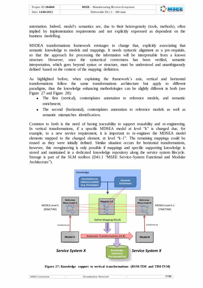
Project ID 284860 MSEE – Manufacturing SErvices Ecosystem
e Date: 14/06/2012 Deliverable D11.3 – M8 issue
MSEE Consortium Dissemination: Restricted 37/53
automation. Indeed, model’s semantics are, due to their heterogeneity (tools, methods), often
implied by implementation requirements and not explicitly expressed as dependent on the business modelling.
MSDEA transformations framework envisages to change that, explicitly associating that semantic knowledge to models and mappings. It needs syntactic alignment as a pre-requisite,
so that the approach for processing the information will be interpretable from a known structure. However, once the syntactical correctness has been verified, semantic
interpretation, which goes beyond syntax or structure, must be understood and unambiguously defined based on the context of the mapping definition.
As highlighted before, when explaining the framework’s axis, vertical and horizontal transformations follow the same transformations architecture but apply to different
paradigms, thus the knowledge enhancing methodologies can be slightly different in both (see Figure 27 and Figure 28):
The first (vertical), contemplates annotation to reference models, and semantic
enrichment;
The second (horizontal), contemplates annotation to reference models as well as
semantic mismatches identification.
Common to both is the need of having traceability to support reusability and re-engineering. In vertical transformations, if a specific MDSEA model at level “k” is changed due, for example, to a new service requirement, it is important to re-engineer the MDSEA model
elements mapped to the changed element, at level “k-1”. The remaining mappings could be reused as they were initially defined. Similar situation occurs for horizontal transformations,
however, this reengineering is only possible if mappings and specific supporting knowledge is stored and maintained in a dedicated knowledge repository along the service system lifecycle. Storage is part of the SLM toolbox (D41.1 "MSEE Service-System Functional and Modular
Architecture”).
Figure 27: Knowledge support to vertical transformations (BSM-TIM and TIM-TS M)
Knowledge
Knowledge repository
(for traceability)
Define Mapping θ(A,B)
Conforms to
Automatic Transformations τ(A,B)
Rea
lizes
Mapping A-B
Model A
Reference Meta-model A
Reference Meta-model B
Conforms to
Model B
Semantic Enrichment
MDSEA Level k
(BSM/TIM)
MDSEA Level k-1
(TIM/TSM)
Annotations toreference models (e.g. Ontologies)
Service System X Service System X

Project ID 284860 MSEE – Manufacturing SErvices Ecosystem
e Date: 14/06/2012 Deliverable D11.3 – M8 issue
MSEE Consortium Dissemination: Restricted 38/53
6.3.1 Annotations to Reference Models
A mark, tag, or annotation is applied to an element of the MDSEA meta-model in order to indicate detailed mapping information concerning how that element it is to be transformed.
The set of marks can be viewed as an overlay (or transparency) placed over the MDSEA meta-models and templates for the purpose of the transformation. They specify the rules according to which instances in a model are to be transformed to fill the parameters of the
target MDSEA templates.
Semantic annotations ease reuse, cross-reference and unambiguous terminology. Following the illustration of Figure 27, besides establishing a direct correspondence among the source and target models elements (both belonging the same service system but different MDSEA
levels in vertical transformations, or same MDSEA level but different service systems in horizontal ones), they can be annotated using meta-knowledge from external reference models
(e.g. ontologies) to improve and determine exactly how the element is to be transformed and become conformant to the target format. If the mapping is not a one-to-one mapping between one source concept to one target concept, but a one-to-many mapping, the transformation
needs additional semantic annotations or semantic support to produce the target concepts. In that case, these annotations have to provide information about the target concept to elect.
Figure 28: Knowledge support to horizontal transformations (BSM-BSM, TIM-TIM, and TSM-TSM)
6.3.2 Semantic Enrichment
The semantic enrichment envisaged in MDSEA is a specific type of annotation that enables to
go from more abstract models to more detailed ones, complementing the source models with additional new knowledge (eventually new models) that will become part of the target model.
This enrichment is envisaged only for vertical transformations, where one is specifying the model from the BSM down to TIM and TSM levels:
Knowledge
Knowledge repository
(for traceability)
Define Mapping θ(A,B)
Conforms to
Automatic Transformations τ(A,B)
Rea
lizes
Mapping A-B
Semantic Mismatches
Reference Meta-model A
Reference Meta-model B
Conforms to
Annotations toreference models (e.g. Ontologies)
MDSEA Level k
(BSM/TIM/TSM)
MDSEA Level k
(BSM/TIM/TSM)
Service System A Service System B
Model A Model B

Project ID 284860 MSEE – Manufacturing SErvices Ecosystem
e Date: 14/06/2012 Deliverable D11.3 – M8 issue
MSEE Consortium Dissemination: Restricted 39/53
If annotations are technology specific they are considered part of the TSM, i.e. a TIM
plus all of the technology specific marks constitutes the input to the transformation
process resulting in a TSM;
A BSM plus all the technology independent marks constitutes the input to the
transformation process resulting in a TIM.
6.3.3 Semantic Mismatches
Mismatches are inconsistencies of information that result from “imperfect” mappings. Due to the differences among models (e.g. language, terminology, granularity, etc), almost in every
case, a model mapping leads to a semantic mismatch which can either be lossy or lossless depending on the nature of the related model elements (see table 4).
This notion of mismatch and mismatch annotation can bring a semantic meaning to the type of the relationship being established in the mapping. However, lossy mismatches should be
avoided whenever possible since in lossless cases, the relating element can fully capture the semantics of the related, while in lossy mismatches a semantic preserving mapping to the reference model cannot be built.
Table 4: Semantic Mismatches Examples (adapted from (INTEROP 2006) )
Mismatch Description
Examples
System 1 System 2
Lo
ssle
ss
Naming Different labels for same concept of structure
Granularity Same information decomposed in or
composed by (sub)attributes
Structuring Different design structures for the same
information
SubClass-
Attribute
An attribute, with a predefined value set
(enumeration) represented by a subclass
hierarchy (or vice-versa)
Schema-
Instance
An attribute value in one model can be a part
of the other’s model schema (or vice-versa).
In the example on the right, “Jose” (schema)
could be the “name” of a “Person” (instance)
Encoding Different formats of data or units of measure
for the same attribute
Lo
ssy
Content Different content denoted by the same concept. In the example on the right,
“Person” has different information associated
Coverage Absence of information
-name : string
Person
-personName : string
Person
Naming
-name : string
Person-firstName : string
-lastName : string
Person
Granularity
-name : string
Person
Person
-name : string
Indentification
-hasIdStructuring
PersonPerson
Carlos
SubClass-
Attribute
Jose
+Jose
+Carlos
«enumeration»
GivenNames-name
-name : string
-weight : int
Person
-weight : int
Jose
Schema-
Instance
-weight_Kg : int
Person
-weight_Lbs : int
Person
Encoding
-name : string
Person
-address : string
Person
Content
-name : string
-weight : int
Person
-name : string
Person
Coverage

Project ID 284860 MSEE – Manufacturing SErvices Ecosystem
e Date: 14/06/2012 Deliverable D11.3 – M8 issue
MSEE Consortium Dissemination: Restricted 40/53
Precision
Accuracy of information. In the example on
the right, a predefined value set does not allow the same accuracy of values as the
domain of an integer number.
Abstraction Level of specialisation, e.g. “Ford” is a
specific type of “Car”
6.4 Structured Approach from Transformations
Following the architecture specified, once the mappings (together with the annotations
required) are defined and implemented, automatic transformations between the source and target models can be achieved (see right side of Figure 29 – from top to bottom). Nevertheless, a number of steps need to be accomplished before.
Using an UML-like activity diagram notation, Figure 29, Figure 30, and Figure 31 detail
(from left to right) the steps required to achieve that automatism. If the mapping among the source and target models has been previously defined and stored in the envisaged knowledge repository, one only needs to load it, and implement the transformation using any of the
languages analysed in the literature review (e.g. ATL). If that was not the case then the steps of Figure 31 are required to build the mapping.
Figure 29: Steps towards transformation execution
-weight : int
Person
Person
+heavy
+medium
+light
«enumeration»
WeightCategory
-weight
Precision
Car Ford
Abstraction

Project ID 284860 MSEE – Manufacturing SErvices Ecosystem
e Date: 14/06/2012 Deliverable D11.3 – M8 issue
MSEE Consortium Dissemination: Restricted 41/53
Figure 30: Steps towards MDSEA transformation framework setup
In the mapping definition, the initial activity consists in setting up the MDSEA meta-models (detail of Figure 30). If the language meta-models used in the source and target models are
not available, then they need to be defined, and afterwards, the MDSEA reference meta-models, for each of the BSM/TIM/TSM concept, needs to be analysed and extended when required. In the case the meta-models do exist, it means that they have been processed before
and one can go directly to the mapping activities (Figure 31):
Firstly, verifying if the language mappings have been established, as there is no need
to define them more than once during the entire ecosystem lifecycle;
Secondly, defining the actual mapping between the source and target already using the
language agnostic MSDEA reference meta-models.
Figure 31: Steps towards mappings definition

Project ID 284860 MSEE – Manufacturing SErvices Ecosystem
e Date: 14/06/2012 Deliverable D11.3 – M8 issue
MSEE Consortium Dissemination: Restricted 42/53
7 Specific Implementations: Vertical Transformations from BSM to TIM
Model Driven Engineering (MDE) uses MDA/MDI to specify a standard-based architecture for systems engineering, organized around three different abstraction levels that can be created based on vertical transformations, for example specializations as in BSM to TIM or
TIM to TSM and generalizations vice-versa. However, since the details of each modelling level are different, to perform such transformations it is necessary to define a consistent set of
rules that provide extra meaning to components from one abstraction level to another. This is normally accomplished thanks to a countless number of modelling languages that are already able to define rules for model transformation.
The transformations framework that has been incorporated into MDSEA and described in
section 6, can be applied to perform vertical transformations, using specific MDA/MDI tools to translate from one abstraction level to another. Hence, to provide this transformation process with the required metadata and extra meaning to components, most of the MDA tools
provide a mechanism to perform model annotations at the different abstraction levels.
7.1 Transformation from Extended Actigram Star to BPMN
The transformation of Extended Actigram Star to BPM is an example of vertical transformation from BSM to TIM, where Extended Actigram Star is a process modelling language at BSM level and BPMN is a process modelling language at TIM level. This vertical
transformation gives actors at TIM level the ability to reuse what was done at BSM level avoiding recreating models from scratch.
Figure 32: Extended Actigram Star to BPMN transformation architecture
Figure 32 introduces the architecture followed in order to transform an Extended Actigram
Star model to a BPMN2.0 model. In reference to the generic MSDEA transformations architecture of Figure 24, the Extended Actigram star language is used to model a process at

Project ID 284860 MSEE – Manufacturing SErvices Ecosystem
e Date: 14/06/2012 Deliverable D11.3 – M8 issue
MSEE Consortium Dissemination: Restricted 43/53
BSM level, and in order to transform a process model from BSM to TIM (vertical
transformation) we should transform it into a BPMN model (BPMN2.0 language is used to model a process at TIM level). Knowledge enhancement (semantic annotations, enrichment,
etc.) is not mentioned in this architecture yet since it is a work in progress. Thus, to perform this transformation several prerequisites exist:
A GRAI Extended Actigram Star meta-model with its detailed specification, which
would be the source meta-model.
A reference BPMN2.0 meta-model with its detailed specification, which would be the
target metamodel.
A suitable development environment in order to develop the transformation rules that
govern the mapping.
A transformation language to implement the mapping of concepts from Extended
Actigram Star to BPMN.
A BPMN modelling tool to visualize and edit the resulted BPMN models.
The format of the BPMN models resulting from the ATL transformation should be
accepted by a BPMN modelling tool.
7.1.1 Transformation Scenario
An editor specific to the Extended Actigram Star will produce a model designated by source model, which conforms to the source meta-model (Extended Actigram Star). The goal is to
transform this source model into a BPMN2.0 model, which is the target model, conforming to the target meta-model (BPMN2.0).
As any transformation should be accompanied by a complete understanding of the relationship among the source and target meta-models (Extended Actigram Star and
BPMN2.0) a mapping table representing that relationship will be produced. It identifies the connection points of these languages, and will then be implemented using the transformation language ATL (Atlas transformation language), developed using eclipse as a development
environment. The transformation will result in an XML representation of the BPMN2.0 model.
There is a need to visualize the obtained target model in order to edit it, so a BPMN modeller will be used for this purpose. As different BPMN tools might use slightly different notations,
the XML representation might not fully conform to the format accepted by the BPMN modeller. As a result, another transformation language (e.g. XSLT) might be used in order to
transform the xml representation of the target model into a format accepted by the BPMN modeller.
7.1.2 Extended Actigram Star
Extended Actigram Star is a process modelling language inspired from:
GRAI Extended Actigram: process modelling language created by the two research
groups: GRAI and GRAISOFT, in Bordeaux. The GRAI Extended Actigram
language doesn’t offer a standard computerized meta-model and that will make its
implementation difficult to be handled. An initial effort to meta-model GRAI
Extended Actigram is presented in Figure 16 and Figure 17 of section 5.
IDEF3: scenario-driven process flow description capture method intended to capture
the knowledge about how a particular system works.
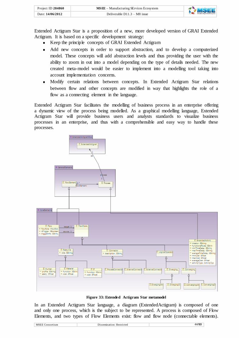
Project ID 284860 MSEE – Manufacturing SErvices Ecosystem
e Date: 14/06/2012 Deliverable D11.3 – M8 issue
MSEE Consortium Dissemination: Restricted 44/53
Extended Actigram Star is a proposition of a new, more developed version of GRAI Extended
Actigram. It is based on a specific development strategy:
Keep the principle concepts of GRAI Extended Actigram
Add new concepts in order to support abstraction, and to develop a computerized
model. These concepts will add abstraction levels and thus providing the user with the
ability to zoom in out into a model depending on the type of details needed. The new
created meta-model would be easier to implement into a modelling tool taking into
account implementation concerns.
Modify certain relations between concepts. In Extended Actigram Star relations
between flow and other concepts are modified in way that highlights the role of a
flow as a connecting element in the language.
Extended Actigram Star facilitates the modelling of business process in an enterprise offering
a dynamic view of the process being modelled. As a graphical modelling language, Extended Actigram Star will provide business users and analysts standards to visualize business
processes in an enterprise, and thus with a comprehensible and easy way to handle these processes.
Figure 33: Extended Actigram Star metamodel
In an Extended Actigram Star language, a diagram (ExtendedActigram) is composed of one and only one process, which is the subject to be represented. A process is composed of Flow
Elements, and two types of Flow Elements exist: flow and flow node (connectable elements).

Project ID 284860 MSEE – Manufacturing SErvices Ecosystem
e Date: 14/06/2012 Deliverable D11.3 – M8 issue
MSEE Consortium Dissemination: Restricted 45/53
The first has a source and a target (flow nodes) while the second, a flow node, can be of four
types: Extended activity, logical operator, resource and connector.
Extended Activity is the basic element of a process that represents the transformation unit of a process. It is a subclass of a process thus it can be decomposed into other extended activities. Extended activity can be a structural activity composed of extended activities or a leaf
activity, which is not composed of any more activities. The role of the structural and leaf activities is to facilitate the choice of zooming in and out of a process.
A resource can be of three types:
Human
Material
IT
These three kinds of resources are proposed in order to adapt our approach to MDSE architecture, which differentiates resources according to these types.
A logical operator can be of four types:
DivergingAnd
DivergingOr
ConvergingAnd
ConvergingOr
The notions of synchronous and asynchronous are not mentioned in this language since it was found that they don’t cover concrete situations in the process modelling.
A connector can be of three types:
Internal
External
Process
7.1.3 BPMN 2.0
The Object Management Group (OMG) has developed a standard Business Process Model and Notation (BPMN). The primary goal of BPMN is to provide a notation that is readily understandable by all business users, from the business analysts that create the initial drafts of
the processes, to the technical developers responsible for implementing the technology that will perform those processes, and finally, to the business people who will manage and
monitor those processes. Thus, BPMN creates a standardized bridge for the gap between the business process design and process implementation (OMG 2011a).
BPMN depicts the end-to-end flow of a business process. The notation has been specifically designed to coordinate the sequence of processes and the messages that flow between
different process participants in a related set of activities. The meta model is available from OMG (2011a).
7.1.4 Mapping of concepts
After analysing the Extended Actigram Star and BPMN2.0 languages, a mapping is created in order to draw the connections between the two languages. The two modelling languages share
some concepts where we can have a direct mapping from one concept to another. However,

Project ID 284860 MSEE – Manufacturing SErvices Ecosystem
e Date: 14/06/2012 Deliverable D11.3 – M8 issue
MSEE Consortium Dissemination: Restricted 46/53
we can notice from the mapping table (Table 5) that some concepts of the Extended Actigram
Star language don’t have a direct correspondence at BPM language. This means that the target model would be poor with a loss of knowledge while passing from one level to another.
Enriching the target meta-model with semantic enrichment and annotations if possible would be a solution to avoid this loss, thus a deep analysis of the BPMN2.0 specification is in progress in order to figure out if there exist no indirect correspondence for every unmapped
concept, and if not, how we can enrich the meta-model.
The red (dark) colour of Table 5 indicates that the mapping is not yet definitive and needs more analysis.
Table 5: Extended Actigram Star to BPMN2.0 mapping
Extended Actigram Star BPMN2.0
Extended Actigram Definitions
Process Process, Participant (Pool)
Extended Activity
Structural Activity
Sub Process
Task Task
Logical operator Gateway
Diverging OR Diverging Exclusive Gateway
Converging OR Converging Exclusive Gateway
DivergingAND Parallel Gateway
Converging AND Parallel gateway
Resource
Material Data Object
Human Lane
IT DataObject
Flow
control Sequence flow
outputInput Sequence flow
support Association (artefact)
ExternalConnector to any
flow other flowNode
Message flow
Flow.isTrigger=”true” ---
Connectors
External Participant (Pool)
Internal Participant(Pool)
Process ---
--- Event
Another issue is that some concepts that are important for the target model such as the Event concept don’t have a correspondence at Extended Activity Star language. As a result, semantic annotations should be added to the source meta-model when reverse transformations
are required.
7.1.5 ATL Transformation
In the scope of the ATL language, the generation of target model elements is achieved through the specification of transformation rules.
Matched Rule
The ATL matched rule mechanism provides ATL developers with a convenient mean to specify the way target model elements must be generated from source model elements. For this purpose, a matched rule enables to specify:
Which source model element must be matched.
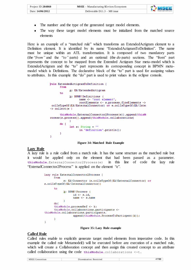
Project ID 284860 MSEE – Manufacturing SErvices Ecosystem
e Date: 14/06/2012 Deliverable D11.3 – M8 issue
MSEE Consortium Dissemination: Restricted 47/53
The number and the type of the generated target model elements.
The way these target model elements must be initialized from the matched source
elements
Here is an example of a “matched rule” which transforms an ExtendedActigram element to a Definition element. It is identified by its name “ExtendedActigramToDefinition”. The name must be unique within an ATL transformation. It is composed of two mandatory parts
(the “from” and the “to” parts) and an optional (the do parts) sections. The “from” part represents the concept to be mapped from the Extended Actigram Star meta-model which is ExtendedActigram and the “to” part represents its corresponding concept in BPMN meta-
model which is Definitions. The declarative block of the “to” part is used for assigning values to attributes. In this example the “do” part is used to print values in the eclipse console.
Figure 34: Matched Rule Example
Lazy Rule
A lazy rule is a rule called from a match rule. It has the same structure as the matched rule but
it would be applied only on the element that had been passed as a parameter. thisModule.ExternalConnector2Process(e) in this line of code the lazy rule
“ExternalConnector2Process” is applied on the element “e”.
Figure 35: Lazy Rule example
Called Rule
Called rules enable to explicitly generate target model elements from imperative code. In this example the called rule Metamodel() will be executed before any execution of a matched rule, which will create a Collaboration concept and then assign this created concept to an attribute
called collaboration using the code thisModule.collaborations <-t.

Project ID 284860 MSEE – Manufacturing SErvices Ecosystem
e Date: 14/06/2012 Deliverable D11.3 – M8 issue
MSEE Consortium Dissemination: Restricted 48/53
Figure 36: Called Rule example
7.1.6 Extended Actigram to BPMN2.0 Transformation Example
Below is a concrete example of a material check process in a shoes fabrication enterprise. In
the two figures we can notice how the concept mapping is implemented and represented in a diagram. This example covers a set of Extended Actigram concepts that can be directly
mapped to BPMN concepts. The following diagram is the Extended Actigram Star graphical representation of the process.
This diagram was drawn “by hand” since the development of the Extended Actigram Star editor is still in progress.
Figure 37: Extended Actigram Star model
The following diagram is the BPMN2.0 graphical representation that should result from the transformation. This diagram was drawn by BPMN2.0 modeller plugin in eclipse. The
diagram translates the result that should be obtained from the mapping table.

Project ID 284860 MSEE – Manufacturing SErvices Ecosystem
e Date: 14/06/2012 Deliverable D11.3 – M8 issue
MSEE Consortium Dissemination: Restricted 49/53
Figure 38: BPMN model

Project ID 284860 MSEE – Manufacturing SErvices Ecosystem
e Date: 14/06/2012 Deliverable D11.3 – M8 issue
MSEE Consortium Dissemination: Restricted 50/53
8 Conclusions
Based on model transformations, the MDSEA has the challenge to unify every step of the enterprise (or virtual enterprise) servitization from its start as a BSM of the services’ business
requirements reflecting the company strategy, through TIM defined functions and behaviour from the perspective of IT, Human and physical means components, to one or more TSMs,
down to generated code and deployable services. The BSM and TIM remain stable as technology evolves, extending and thereby maximizing return on investment. Also, MDSEA answers to the challenge of portability and interoperability, enabling enterprises from
complementary domains and using different technologies to collaborate in the frame of the ecosystem. The proposed transformations framework is flexible to incorporate that and to
address existing models. Therefore, MDSEA transformations approach applies the distinction between vertical and horizontal transformations.
The work reported in this document complements the MDSEA architecture of deliverable D11.1 with the transformations framework and architecture.
Several models have been chosen at each modelling level and transformations identified as required to go from one level to another towards service system implementation, or at the
same level to enable sharing and interoperability. However, moving from a decentralized IT transformations strategy to a centralized one, as envisaged in the chapter 5, requires some
adjustments at the MDSEA service system meta-models and templates presented in deliverable D11.1. Stacking up many modelling languages and connecting them in one is a complex activity as the different languages suitable to model each MDSEA service system
concept need to be carefully studied and the MDSEA meta-models extended to ensure lossless transformations from each language. Hence, BSM and TIM meta-models have been
formalized and divided into “Core Constructs”, specifying the common MSDEA constructs among the multitude of modelling languages used, and the “Reference Meta-models” where language specific constructs extend the core ones with relevant sub-concepts (and their
relationships). This work has been done in collaboration with WP1.5, regarding the design and the development of the SLMToolBox, and to ensure that the implementation of the
MSEE software tools is mutually aligned with the concepts defined by WP1.1. Past research initiatives have specified integrated approaches for enterprise systems
development and interoperability, e.g. MDI. They envisaged a framework of model transformations with the possibility of having ontological support that is clearly applicable in
the scope of MDSEA. However, concerning specific transformations, not much literature has been found on CIM to PIM implementations. Therefore, the major target of this deliverable is not only to adjust and improve such transformations frameworks to the needs of the virtual
enterprise and the servitization process, but also to demonstrate the feasibility of Business Service Models (BSM) to Technical Independent Models (TIM) transformations.
A specific example to transform GRAI Extended Actigram to BPMN2.0 has been presented and its implementation is currently ongoing, applying the principles proposed in the MDSEA
transformation framework. Considering the transformation languages analysed, ATL has currently the largest user-base and the most extensive information available such as reference
guides, tutorials, programmers’ forums, etc., thus it was decided to use ATL to implement model and language transformations in the scope of MDSEA. Even if all the constructs are not yet used in the transformation mechanisms presented, further work is expected in the
upcoming WP1.1 deliverables and other implementations (e.g. from horizontal transformations, TIM to TSM, or usage of semantic annotations) will be available later, as
well the specifications required for their implementation.

Project ID 284860 MSEE – Manufacturing SErvices Ecosystem
e Date: 14/06/2012 Deliverable D11.3 – M8 issue
MSEE Consortium Dissemination: Restricted 51/53
Also, for future work to be reported in the upcoming D11.4 at M15 is the issue of mappings formalization (modelling). Current technologies, such as ATL, support transformations
implementation, however, none support formalization. Following the transformations architecture, service model mappings should be formalized also as models to ensure reusability and traceability.
Project ID 284860 MSEE – Manufacturing SErvices Ecosystem
e Date: 14/06/2012 Deliverable D11.3 – M8 issue
MSEE Consortium Dissemination: Restricted 52/53
9 References
Agostinho, C., Correia, F. & Jardim-Goncalves, R. (2010) Interoperability of Complex Business Networks by Language Independent Information Models. In 17th ISPE International Conference on Concurrent Engineering (CE2010). Cracow, Poland: Springer-Verlag. Available at: http://www.springerlink.com/content/q775010855762526/.
Ambler, S.W. (2008) Effective Practices for Modeling and Documentation. Agile Modeling (AM) Home Page. Available at: http://www.agilemodeling.com/ [Accessed July 12, 2012].
Athena (2005) Deliverable D.A6.1: Specification of a Basic Architecture Reference Model, Athena IP Project (FP6 IST-507849).
Athena IP (2006) ATHENA Interoperability Framework (AIF). Available at: http://modelbased.net/aif/index.html [Accessed January 20, 2012].
Benguria, G., Larrucea, X., Elvesæter, B., Neple, T., Beardsmore, A. & Friess, M. (2006) A Platform Independent Model for Service Oriented Architectures. In 2nd International Conference on Interoperability for Enterprise Software and Applications (I-ESA’06). Bordeaux, France.
Czarnecki, K. & Helsen, S. (2006) Feature-based survey of model transformation approaches. IBM Systems Journal, 45 (3), p.pp.621-645.
Doumeingts G., Ducq Y. (2001) Enterprise Modelling techniques to improve efficiency of enterprises. in International Journal of Production Planning and Control - Taylor & Francis – Vol. 12, number 2, Mars 2001, pp 146-163
Eclipse foundation (2011) ATL Transformation Language. Available at: http://eclipse.org/atl/ [Accessed September 7, 2011].
Elvesæter, B., Hahn, A., Berre, A.-jørgen & Neple, T. (2005) Towards an interoperability framework for model-driven development of software systems. In 1st International Conference on Interoperability for Enterprise Software and Applications (I-ESA’05). Springer. Available at: http://www.springerlink.com/index/L10NU4306N054T6G.pdf [Accessed May 3, 2011].
Enterprise Interoperability Cluster (2008) Enterprise Interoperability Research Roadmap, Version 5.0, European Commision. Available at: http://cordis.europa.eu/fp7/ict/enet/ei-research-roadmap_en.html [Accessed May 3, 2011].
Grangel, R., Correa, K., Antonio, F.D., Bourey, J.-pierre & Berre, A.J. (2007) Analysing CIM2PIM Approaches to Improve Interoperability. In 3rd International Conference on Interoperability for Enterprise Software and Applications (I-ESA’07). Funchal, Madeira.
Grangel, R., Salem, R., Bourey, J.-pierre, Daclin, N. & Ducq, Y. (2007) Transforming GRAI Extended Actigrams into UML Activity Diagrams: a First Step to Model Driven Interoperability. In 3rd International Conference on Interoperability for Enterprise Software and Applications (I-ESA’07). Funchal, Madeira.
Greenfield, J., Short, K., Cook, S. & Kent, S. (2004) Software Factories: Assembling Applications with Patterns, Models, Frameworks, and Tools, Wiley.
INCOSE, T.O. (2007) Systems Engineering Vision 2020 (INCOSE-TP-2004-004-02), INCOSE. Available at: www.incose.org/ProductsPubs/pdf/SEVision2020_20071003_v2_03.pdf [Accessed April 9, 2012].
INTEROP (2006) DELIVERABLE D.A3.3: Semantic Annotation language and tool for Information and Business Processes Apendix F: User Manual, INTEROP NoE Project (FP6 IST-1-508011).
INTEROP (2005a) Deliverable DTG2.1: REPORT ON MODEL ESTABLISHMENT, INTEROP

Project ID 284860 MSEE – Manufacturing SErvices Ecosystem
e Date: 14/06/2012 Deliverable D11.3 – M8 issue
MSEE Consortium Dissemination: Restricted 53/53
NoE Project (FP6 IST-1-508011). Available at: http://interop-vlab.eu/ei_public_deliverables/interop-noe-deliverables/tg2-model-driven-interoperability/DTG2.1/.
INTEROP (2005b) Deliverable DTG3.1 (MoMo.2): MoMo Roadmap, INTEROP NoE Project (FP6 IST-1-508011). Available at: http://interop-vlab.eu/ei_public_deliverables/interop-noe-deliverables/tg3-model-morphisms/DTG3.1/.
Jouault, F. & Kurtev, I. (2007) On the interoperability of model-to-model transformation languages. Science of Computer Programming, 68, p.pp.114-137.
Lubell, J., Peak, R.S., Srinivasan, V. & Waterbury, S.C. (2004) STEP, XML, and UML: Complementary Technologies. In DETC 2004: ASME 2004 Design Engineering Technical Conferences and Computers and Information in Engineering Conference. Salt Lake City, Utah USA: Asme. Available at: http://link.aip.org/link/ASMECP/v2004/i46970/p915/s1&Agg=doi.
Mosterman, P.J. & Vangheluwe, H. (2004) Computer Automated Multi-Paradigm Modeling: An Introduction. SIMULATION, 80 (9), p.pp.433-450.
OMG (2011a) Business Process Model and Notation (BPMN) - version 2.0 (formal/2011-01-03). Available at: http://www.omg.org/spec/BPMN/2.0/PDF/.
OMG (2003) MDA Guide Version 1.0.1 (omg/2003-06-01), Object Management Group. Available at: http://www.omg.org/cgi-bin/doc?omg/03-06-01.pdf [Accessed September 7, 2011].
OMG (2008) Meta Object Facility (MOF) 2.0 Query/View/Transformation Specification - Version 1.0 (formal/2008-04-03). Available at: http://www.omg.org/spec/QVT/1.0/PDF/.
OMG (2011b) OMG Unified Modeling LanguageTM (OMG UML), Infrastructure - version 2.4.1. Available at: http://www.omg.org/spec/UML/2.4.1/Infrastructure/PDF/.
OMG (2010) Object Constraint Language - version 2.2 (formal/2010-02-01). Available at: http://www.omg.org/spec/OCL/2.2/PDF/.
Salem, R., Grangel, R. & Bourey, J.-pierre (2008) A comparison of model transformation tools: Application for Transforming GRAI Extended Actigrams into UML Activity Diagrams. Computers in Industry, 57 (7), p.pp.682-693.
Thomas, D. & Barry, B.M. (2003) Model Driven Development: The Case for Domain Oriented Programming. In Companion of the 18th annual ACM SIGPLAN conference on Object-oriented programming, systems, languages, and applications (OOPSLA’03). ACM Press.
Tolk, A. (2006) What comes after the semantic Web - PADS impli-cations for the dynamic Web. In 20th Workshop on Principles of Advanced and Distributed Simulation (PADS’06).
Tolk, A. & Muguira, J.A. (2003) The Levels of Conceptual Interoperability Model. In 2003 Fall Simulation Interoperability Workshop. Orlando, Florida, USA: Simulation Interoperability Standards Organiza-tion.
Wang, Wenguang, Tolk, A. & Wang, Weiping (2009) The Levels of Conceptual Interoperability Model: Applying Systems Engineering Principles to M&S. In Spring Simulation Multiconference (SpringSim’09). San Diego, CA, USA.
Zacharewicz, G., Chen, D. & Vallespir, B. (2009) Short-Lived Ontology Approach for Agent/HLA Federated Enterprise Interoperability. In I-ESA’09. Benjing, China.