Embed Size (px)
Citation preview
BusWorks® 900EN Series – EtherNet/IP™10/100MB Industrial Ethernet I/O Modules
Model 981EN-6012 12 Active-Low Digital InputsModel 982EN-6012 12 Sinking Digital OutputsModel 983EN-6012 12 Tandem Digital Input/Output
USER’S MANUAL
EtherNet/IPCONFORMANCE TESTED™
ACROMAG INCORPORATED Tel: (248) 624-154130765 South Wixom Road Fax: (248) 624-9234P.O. BOX 437Wixom, MI 48393-7037 U.S.A.
Copyright 2004, Acromag, Inc., Printed in the USA.Data and specifications are subject to change without notice. 8500-749-A04M000
BusWorks® 981/982/983EN Module User’s Manual EtherNet/IP™ Digital I/O__________________________________________________________________
_______________________________________________________________________________________Acromag, Inc. Tel:248-624-1541 Fax:248-624-9234 Email:[email protected] http://www.acromag.com
2IMPORTANT SAFETY CONSIDERATIONSYou must consider the possible negative effects of power, wiring,component, sensor, or software failure in the design of any type ofcontrol or monitoring system. This is very important where propertyLoss or human life is involved. It is important that you performsatisfactory overall system design and it is agreed between you andAcromag, that this is your responsibility.
GETTING STARTEDMOUNTING AND DIMENSIONS……………………… 3CONTROLS & INDICATORS..………………………… 3ISOLATION BARRIERS..………………………………. 3I/O PULLUP RESISTOR INSTALLATION…………… 4CONNECTIONS…………………………………………. 4
DIN-Rail Mounting And Removal……………… 4Network…………………………………………….. 5Power……………………………………………….. 6Digital Inputs……………………………………… 7Digital Outputs..………………………………….. 8Earth Ground..………………………………….…. 9
WEB BROWSER………………………………………... 10Home Page………………………………………… 10Password Configuration Page.………………... 11Network Configuration Page…………………… 12Discussion Topic – IP Addressing……………. 14Test Page………………………………………….. 16
TROUBLESHOOTING………………………………….. 17Diagnostics Table……………………………..…. 18Trouble Browsing Your Module?..................... 19Getting Out Of Trouble………………………….. 19
TECHNICAL REFERENCEKEY FEATURES………………………………………… 20HOW IT WORKS………….…………………………….. 21ETHERNET/IP…………………………………………… 22
Object Models………..…….….…………………. 22EDS File (Electronic Data Sheet)………………. 29
MODBUS TCP/IP….………………..………………….. 32Modbus Registers..………………………………. 32Register Functions………………………………. 32Register Mirroring……………………………….. 33Register Data Types……..……………………… 34Register Map……………………………………… 35
SPECIFICATIONS………………………………………. 38Model Numbers….……………………………….. 38Digital Inputs…………………....………………… 38Digital Outputs………………..………………….. 38General Specifications………………………….. 39Enclosure and Physical…………………………. 39Agency Approvals…..……………………………. 40Environmental…………………………………….. 40Ethernet Interface………………………………… 41Controls & Indicators……………………………. 42
ACCESSORY CABLES……..…………………………. 43
TABLE OFCONTENTSSymbols on equipment:
Means “Refer to User’sManual (this manual) foradditional information”.The information of this manualmay change without notice.Acromag makes no warrantyof any kind with regard to thismaterial, including, but notlimited to, the impliedwarranties of merchantabilityand fitness for a particularpurpose. Further, Acromagassumes no responsibility forany errors that may appear inthis manual and makes nocommitment to update, orkeep current, the informationcontained in this manual. Nopart of this manual may becopied or reproduced in anyform without the prior writtenconsent of Acromag, Inc.
EtherNet/IPCONFORMANCE TESTED™
Windows® is a registeredtrademark of MicrosoftCorporation.
The following is a trademarkunder license by ODVA:EtherNet/IP™.
All trademarks are the propertyof their respective owners.
!
BusWorks® 981/982/983EN Module User’s Manual EtherNet/IP™ Digital I/O___________________________________________________________________
_______________________________________________________________________________________Acromag, Inc. Tel:248-624-1541 Fax:248-624-9234 Email:[email protected] http://www.acromag.com
3
44 41 33
PWR
NET
WO
RK
13
CH
1
16
RTN
21 24
CH
6
TB3
TB1
CH10
EXC3
EXC2
GND
46 4345
RX
42
DC
-
DC+
32 31
TB1
11 1412
CH
2
CH
0
TB2
2215
CH
4
CH
3
TX
5V/3V
TB4
TB4
25 2623
CH
7
CH
5
RTN
DCPWR
EXC1
RTN
CH
9
CH11
TB2
CH
8
DIGITAL I/O
DIGITAL IN or OUT
DIGITAL I/O
DIGITAL IN or OUT
DIGITAL I/O
DIGITAL IN or OUT
TRANSFORMER
TB3
981/982/983ENISOLATIONDIAGRAM
TRANSFORMER
46 44 43 41 33
DC-
32
9
5 6
1 20
11
7
3
TB1
EXC
111
RTN
CH
1
13
CH
10
CH
2
14
CH
9
RTN
16
EXC
3 TB4
TB4
EXC
2
21
CH
4
22
CH
6
24
GN
D
CH
7
25
TB3
CH
. I/O
STA
TUS
RST
ACTLINK
ST
45 42
PWR
DC+
31
LC
8
4
RUN
10
3.7
5(9
5.3)
TB1 C
H 0
12
CH
11
TB2
TB2C
H 3
15
CH
8
CH
5
RTN
2623
TB3
4.6
8(1
18.9
)
3.90(99.1)
ETHERNET
DFT
DIGITAL IN or OUT
2.3
4(5
9.4)
DIGITAL IN or OUT
Acromag
DIGITAL IN or OUT
1.05(26.7)
"T" RAIL DIN MOUNTING DIN EN 50022, 35mm 4.35
(110.5)NOTE: Dimensions Are INCHES (MILLIMETERS).
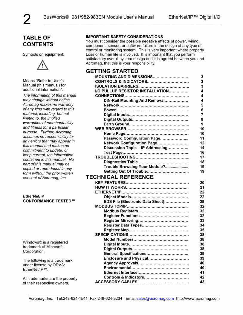
MODEL 981/982/983EN ENCLOSURE DIMENSIONS
Model 983EN-6012 Shown(981EN-6012 & 982EN-6012 Similar)
8
4
RUN
10
5 6 7
11
46
14
43
22 25
32
0
CH
. I/O
STA
TUS 1 2 3
ST
RTN
CH
9
GND DC
-
EXC1
CH
2
TB4
CH
4
CH
7
TB3
RSTDFT
LINK
9 11
TB1
13 1612 15
44 4145 42
TB2
21 2423
33
26
31
ACT
TB1
CH
10
EXC3
CH
11
CH
8
TB2
DC+
TB3
CH
1
RTN
CH
0
CH
3
EXC2
CH
6
CH
5
RTN
ETHERNET
TB4
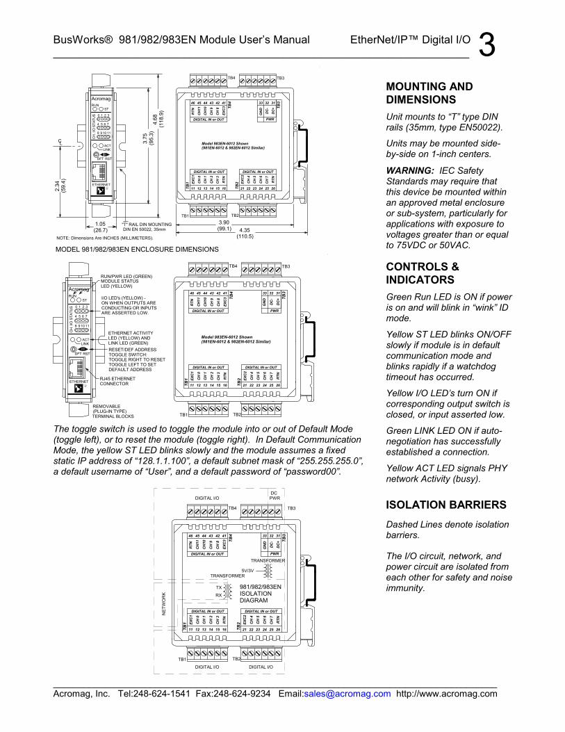
RJ45 ETHERNETCONNECTOR
REMOVABLE
RESET/DEF ADDRESSTOGGLE SWITCH:TOGGLE RIGHT TO RESETTOGGLE LEFT TO SETDEFAULT ADDRESS
I/O LED's (YELLOW) -ON WHEN OUTPUTS ARECONDUCTING OR INPUTSARE ASSERTED LOW.
Acromag
RUN/PWR LED (GREEN)MODULE STATUSLED (YELLOW)
DIGITAL IN or OUTDIGITAL IN or OUT
Model 983EN-6012 Shown(981EN-6012 & 982EN-6012 Similar)
PWRDIGITAL IN or OUT
(PLUG-IN TYPE)TERMINAL BLOCKS
ETHERNET ACTIVITYLED (YELLOW) ANDLINK LED (GREEN)
The toggle switch is used to toggle the module into or out of Default Mode(toggle left), or to reset the module (toggle right). In Default CommunicationMode, the yellow ST LED blinks slowly and the module assumes a fixedstatic IP address of “128.1.1.100”, a default subnet mask of “255.255.255.0”,a default username of “User”, and a default password of “password00”.
MOUNTING ANDDIMENSIONSUnit mounts to “T” type DINrails (35mm, type EN50022).
Units may be mounted side-by-side on 1-inch centers.
WARNING: IEC SafetyStandards may require thatthis device be mounted withinan approved metal enclosureor sub-system, particularly forapplications with exposure tovoltages greater than or equalto 75VDC or 50VAC.
CONTROLS &INDICATORSGreen Run LED is ON if poweris on and will blink in “wink” IDmode.
Yellow ST LED blinks ON/OFFslowly if module is in defaultcommunication mode andblinks rapidly if a watchdogtimeout has occurred.
Yellow I/O LED’s turn ON ifcorresponding output switch isclosed, or input asserted low.
Green LINK LED ON if auto-negotiation has successfullyestablished a connection.
Yellow ACT LED signals PHYnetwork Activity (busy).
ISOLATION BARRIERSDashed Lines denote isolationbarriers.
The I/O circuit, network, andpower circuit are isolated fromeach other for safety and noiseimmunity.
BusWorks® 981/982/983EN Module User’s Manual EtherNet/IP™ Digital I/O__________________________________________________________________
_______________________________________________________________________________________Acromag, Inc. Tel:248-624-1541 Fax:248-624-9234 Email:[email protected] http://www.acromag.com
4
TB1
TB4
R7
X1
X3
CH
. I/O
STA
TUS
9
5 6
1 2
10
1 2
CH7
3 4 5 6 7 8 2 3
7 6
5 6
CH1
4 3
CH9
8
1
ETHERNET
ACT
ST
Acromag
EXC+
RTN
RTN EXC+
TB2
EXC+
RTN
TB3
X2
R2
LINK
DFT RST
0
11
7
3
8
4
RUN
RESISTORNETWORK
1 4
CH3CH2CH5 CH4
8 5
CH10CH11
7
CH0
2
CH8
PORT 1 PORT 0
R11
PORT 2
USE SMALL SCREW DRIVERTO PRY OFF SIDE COVER.COVER IS HELD IN PLACEWITH EIGHT SNAP PINS.
BASE BOARD
SOCKET
BOURNS 4308H-102-562OR EQUIVALENT
WHEN REPLACING COVER,ALIGN ALL PINS, THEN SNAPTOGETHER IN SEQUENCETO SECURE COVER.
CH6
PLUG-IN I/O BOARD(Turned Face Up)
CAREFULLY SEPARATEI/O BOARD FROM BASEBOARD.
PORT 1(CH4-7)
PORT 0(CH0-3)
PORT 2(CH8-11)
CAUTION: HANDLE CIRCUITUSING ESD-SAFE PROCEDURES.
981EN/982EN/983EN SHOWNWITH SIDE COVER REMOVEDAND I/O BOARD SEPARATED
PULLUPS ARE LOCATED IN SOCKETSON PLUG-IN I/O BOARD AS SHOWN HERE
5.6K x4 ISOLATED0.5W RESISTORS SERIES 981PB/982PB/983EN SIP
PULLUP RESISTOR SOCKET LOCATION
EACH PORT HAS A SIP RESISTORLOCATED AS SHOWN AT RIGHT.SIP RESISTORS PULL-UP THE I/OCHANNEL TO THE EXC SUPPLY. SIPS ARE INSTALLED IN SOCKETSX1, X2, AND X3. PORT 0 SIP = R2 INSTALLED IN X1PORT 1 SIP = R7 INSTALLED IN X2PORT 2 SIP = R11 INSTALLED IN X3 THE SIP IS AN ISOLATED RESISTORNETWORK OF 4 ELEMENTS.FACTORY SIP VALUE IS 5.6K OHMS.POWER IS 0.5W PER ELEMENT. THE EVEN-NUMBERED PINS OFTHE SOCKETS ARE TIED TO THEPORT EXCITATION TERMINAL. WHEN REPLACING SIPS ORCHANGING VALUES, WATCHTHAT POWER DISSIPATIONDOES NOT EXCEED SIP RATING.
45 44 42 41 33
DC+
31
12 13 15 16 21 23 24 26TB1
GND
46 43
PWR
DC-
32
11 14 22
TB4
25
TB3
TB3
PUSH
TB2
"T" TYPE DIN RAIL
PUSH SCREWDRIVER AS SHOWNTO TILT AND LIFT MODULE OFF RAIL
Remove Terminal Blocks On ThisSide To Provide Clearance
Any Series 9XXEN Ethernet Module
MODULE REMOVALFROM DIN RAIL
PRY WITH SCREWDRIVERINSERTED IN SLOT HERE(DO NOT TWIST TO AVOIDDAMAGING PLASTIC TAB)
USE YOUR FINGER TO APPLYDOWNWARD PRESSURE HEREAS YOU LIFT AND TILT MODULETO REMOVE IT FROM RAIL
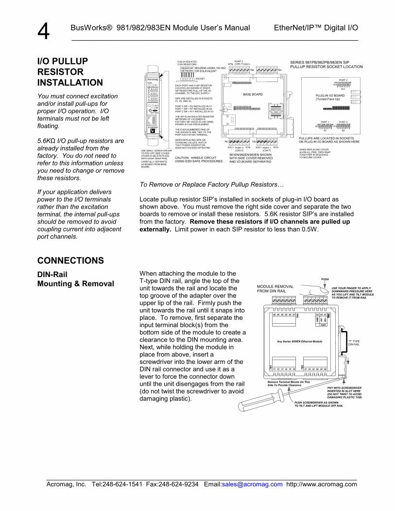
To Remove or Replace Factory Pullup Resistors…
Locate pullup resistor SIP’s installed in sockets of plug-in I/O board asshown above. You must remove the right side cover and separate the twoboards to remove or install these resistors. 5.6K resistor SIP’s are installedfrom the factory. Remove these resistors if I/O channels are pulled upexternally. Limit power in each SIP resistor to less than 0.5W.
When attaching the module to theT-type DIN rail, angle the top of theunit towards the rail and locate thetop groove of the adapter over theupper lip of the rail. Firmly push theunit towards the rail until it snaps intoplace. To remove, first separate theinput terminal block(s) from thebottom side of the module to create aclearance to the DIN mounting area.Next, while holding the module inplace from above, insert ascrewdriver into the lower arm of theDIN rail connector and use it as alever to force the connector downuntil the unit disengages from the rail(do not twist the screwdriver to avoiddamaging plastic).
I/O PULLUPRESISTORINSTALLATIONYou must connect excitationand/or install pull-ups forproper I/O operation. I/Oterminals must not be leftfloating.
5.6KΩ I/O pull-up resistors arealready installed from thefactory. You do not need torefer to this information unlessyou need to change or removethese resistors.
If your application deliverspower to the I/O terminalsrather than the excitationterminal, the internal pull-upsshould be removed to avoidcoupling current into adjacentport channels.
CONNECTIONSDIN-RailMounting & Removal

BusWorks® 981/982/983EN Module User’s Manual EtherNet/IP™ Digital I/O___________________________________________________________________
_______________________________________________________________________________________Acromag, Inc. Tel:248-624-1541 Fax:248-624-9234 Email:[email protected] http://www.acromag.com
5
1
87
54
21
100M100M
CLIP
8
6
3
CABLE
81
10Base-TCAT 5 UTP/STP
Not UsedNot Used
Not UsedNot Used
Receive -Receive +
RJ-45 CONNECTOR
SPEED
PIN
DISTANCE
Transmit -
Transmit +
MDI-X WIRING
100Base-TCAT 3, CAT 4, or CAT 5 UTP/STP
Note Crossover ConnectionsMINIMUM RECOMMENDED CABLE
Not UsedNot Used
Not UsedNot Used
Transmit -Transmit + ETHERNET PORT
RJ45 MDI AND MDI-X CONNECTIONS
Receive -
Receive +
MDI WIRING
The Ethernet port of this module is wired MDI and does not includeautomatic crossover. The Ethernet port of your PC is also wired MDI andmay not include automatic crossover. As such, you must use a crossovercable like that shown below when connecting this device directly to a PC.
1
1
3
6
1
6
23
1
82
81
8
8
1
PINS: 1 TO 32 TO 63 TO 16 TO 2
RJ45 (Clip Side Down) RJ45 (Clip Side Down)
FOR DIRECT PC TOETHERNET MODULECONNECTIONS
CROSSOVER CABLEFOR MDI TO MDIOR MDI-X TO MDI-X CROSSOVER
CONNECTIONS
9 10
5 6
1 2
CH
. I/O
STA
TUS
ACT
8 11
4 7
0 3
STRUN
Acromag
ETHERNET
RST
LINK
DFTHOST PC
(Use Crossover Cable)
Note: This MDI-to-MDI connection requires the use of a crossover cable.HOST PC CONNECTED DIRECTLY TO A MODULE
CAT-5 UTP CABLEUP TO 100 METERS
Acromag 983EN-6012Ethernet Module. The ethernet port of thismodule is not automaticMDI/MDI-X crossoverand is wired MDI.
CONNECTIONSNetworkFor 100Base-TX systems, at aminimum, use data gradeUnshielded Twisted-Pair(UTP) wiring that has a 100Ωcharacteristic impedance andmeets the EIA/TIA Category 5wire specifications.
It is recommended that youuse a crossover CAT-5 cableto connect this device to yourPC.
For 10Base-T systems, youmay use Category 3, Category4, or Category 5/5E UTP/STPcable.
In either case, you are limitedto 100 meters between anytwo devices.
A crossover cable simplyconnects the differentialtransmit pair on each end, tothe receive pair on theopposite end.
Use a standard (direct) cablewhen connecting to a hub orswitch port, which aregenerally wired MDI-X.
BusWorks® 981/982/983EN Module User’s Manual EtherNet/IP™ Digital I/O__________________________________________________________________
_______________________________________________________________________________________Acromag, Inc. Tel:248-624-1541 Fax:248-624-9234 Email:[email protected] http://www.acromag.com
6
S1 S2
DC
-
33
DC
+
32
RS
109
65
21 3
98
54
10
DA
11
7
2 3
ST
8
4
0
10
76
2 3
ST
98
54
10
DA
11
7
2 3
ST
100M
LK /
P1
X3 X4
TB3
CH
. I/O
STA
TUS
ACT
ACT
CH
. I/O
STA
TUS
RUN
X5X5
X4
X1G
ND
34
DC
+
31
8
4
0
RUN
DA
LINK
11
7
ST
LINK
10
6
DARS
LINK
9 11
5
1
RS
LINK
10
6
RUN
CO
L
ACT
X5
X3
X2
X1 X2
PGMPORT
PUSH
TO RESE
T
ACT
ACT
ETHERNET
Acromag
CH
. I/O
STA
TUS
CH
. I/O
STA
TUS
POWER
RS
RUN
RUN
ETHERNET SWITCH
Acromag
ETHERNET
ETHERNET
Acromag
Acromag
ETHERNET
Acromag
HOST PC
Acromag 9xxEN-4012or 9xxEN-6012Ethernet Modules. The ethernet port of thesemodules are not automaticMDI/MDI-X crossover, butthe use of an auto-crossingswitch eliminates the needto make a distinction betweenstraight-through and crossovercables.
(Straight-Through or Crossover Cable)
CAT-5 UTP CABLEUP TO 100 METERS
(Straight-Through or Crossover Cable)
Order Acromag Cable Model 5035-355
CAT-5 UTP CABLEUP TO 100 METERS
ETHERNETSWITCH
DIP SW S1/S2CFG OPTIONS
CAT-5 UTP CABLEUP TO 100 METERS
(Straight-Through or Crossover Cable)
(Straight-Through or Crossover Cable)
CAT-5 UTP CABLEUP TO 100 METERS
CAT-5 UTP CABLEUP TO 100 METERS
The ethernet port of the PC isgenerally not automatic MDI/MDI-Xcrossover and is wired MDI.
Because the Acromag ethernet switch900EN-S005 is automatic MDI/MDI-Xcrossover, use of a direct (straight-through)or crossover cable is permissible.
IMPORTANT: IF THE HOST PC CONNECTS DIRECTLY TO THE MODULE,YOU MUST USE A CROSS-CONNECT CABLE (MDI-X), AS BOTH THE PCAND THE 9XXEN MODULE ETHERNET PORTS ARE WIRED MDI. ETHERNET SWITCHES AND HUBS ARE WIRED MDI-X.THE ACROMAG ETHERNET SWITCH IS AUTOMATIC MDI/MDI-X ANDELIMINATES THE NEED FOR MAKING A DISTINCTION BETWEENTHE USE OF STRAIGHT-THROUGH (MDI) AND CROSSOVER (MDI-X)CABLE CONNECTIONS.
Acromag 900EN-S0055-Port Ethernet Switchor equivalent. The ethernet ports of thisswitch are automatic MDI/MDI-Xcrossing and do not requirecrossover cables.
USE OF AN ETHERNET SWITCH TO NETWORKA HOST PC TO MORE THAN ONE MODULE
Acromag offers a straight-through patch cable (Model 5035-355), or acrossover cable (Model 5035-360) for use with Series 9xxEN modules.
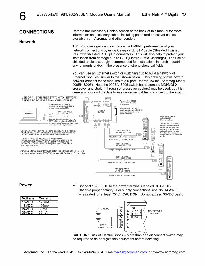
Refer to the Accessory Cables section at the back of this manual for moreinformation on accessory cables including patch and crossover cablesavailable from Acromag and other vendors.
TIP: You can significantly enhance the EMI/RFI performance of yournetwork connections by using Category 5E STP cable (Shielded TwistedPair) with shielded RJ45 plug connectors. This will also help to protect yourinstallation from damage due to ESD (Electro-Static Discharge). The use ofshielded cable is strongly recommended for installations in harsh industrialenvironments and/or in the presence of strong electrical fields.
You can use an Ethernet switch or switching hub to build a network ofEthernet modules, similar to that shown below. This drawing shows how tonetwork-connect these modules to a 5-port Ethernet switch (Acromag Model900EN-S005). Note the 900EN-S005 switch has automatic MDI/MDI-Xcrossover and straight-through or crossover cable(s) may be used, but it isgenerally not good practice to use crossover cables to connect to the switch.
Connect 15-36V DC to the power terminals labeled DC+ & DC-.Observe proper polarity. For supply connections, use No. 14 AWGwires rated for at least 75°C. CAUTION: Do not exceed 36VDC peak.
+
TB3
PWR
33 GND
DC+31
EARTHGROUND
15 TO 36VDC
DC-32
TB3INPUT POWERIS ISOLATED
CAUTION: Risk of Electric Shock – More than one disconnect switch maybe required to de-energize this equipment before servicing.
CONNECTIONS
Network
Power
Voltage Current15VDC 123mA18VDC 106mA24VDC 80mA36VDC 59mA

BusWorks® 981/982/983EN Module User’s Manual EtherNet/IP™ Digital I/O___________________________________________________________________
_______________________________________________________________________________________Acromag, Inc. Tel:248-624-1541 Fax:248-624-9234 Email:[email protected] http://www.acromag.com
7
5.6K
ROFF (0)
+5V
ON (1)
I/O
100K
ON (1)
RTN
I/O
EXC
TO OTHER 3CHAN OF PORT
5.6K
100KON (1) R
ON (1)
OFF (0)
OFF (0)
SIP RESISTORINSTALLEDIN SOCKET
TVS(48V)
EXC
(Active-LOW)
+5V
RTN
(Active-LOW)
TO OTHER 3CHAN OF PORT
CHLED
OFF (0)
SIP RESISTORINSTALLEDIN SOCKET
TVS(48V)
ON (1) OFF (0) CHLED
SIMPLIFIED 983PB CHANNEL (Tandem Input/Output)SIMPLIFIED 981PB CHANNEL (Input Only)
IMPORTANT – External Fuse: If unit is powered from a supply capable ofdelivering more than 1A to the unit, it is recommended that this current belimited via a high surge tolerant fuse rated for a maximum current of 1A orless (for example, see Bel Fuse MJS1).
Connect digital input signals to the input terminals. Refer to the figuresbelow:
16 RTN
1513
12
TB1
OR
+5V
1411 EXC
5.6K
100K
DIG
ITAL
IN o
r OUT
CH03
CH01CH00
OPENCOLLECTOROR DRAIN
TB1
CH02
+5V
983EN SIMPLIFIED INTERNAL I/OCONNECTIONS (ONE CHANNEL)
LOW-SIDESWITCH
PULLUP(IN SOCKET)
SHIELDED CABLE
DIGITAL INPUT CONNECTIONS
Refer to the examples below for examples of other types of inputconnections.
I
I/O R
RTN
100KV
N.O. 983ENONLY
+5VEXC5.6K
CH
OTHER THREECHAN OF PORT
CH LED IS ON FORACTIVE-LOW INPUT
ON 983EN UNITS, MAKESURE OUTPUT IS OFF(0) FOR INPUT ONLYAPPLICATIONS.
SIP INSTALLED
981EN & 983EN
DRY-CONTACT RELAY CONNECTIONS - NORMALLY OPEN
ADJUST VOLTAGE (V) ASREQUIRED TO CHANGEEXCITATION CURRENT( I)OR CHANGE SIP RESISTORVALUE.
CONNECTIONS
Power
Digital Inputs(981EN & 983EN Only)
Inputs are active-low.
Input threshold is TTLcompatible.
Limit Input Voltages to35V maximum.
Note: Do not allow EXC orunused inputs to float. If pull-ups are installed, this willcause one I/O signal to pull theother floating port channels viathe pull-ups and common EXClead connection.
Normally Open Dry ContactRelay.
BusWorks® 981/982/983EN Module User’s Manual EtherNet/IP™ Digital I/O__________________________________________________________________
_______________________________________________________________________________________Acromag, Inc. Tel:248-624-1541 Fax:248-624-9234 Email:[email protected] http://www.acromag.com
8
ON (1)
5.6K
R
EXC
R
+5V
OFF (0)
RTN
OFF (0) TVS(48V)
100KON (1)
CHLED
I/O
CHLED
OFF (0)
EXC
ON (1)
5.6K
OFF (0)
RTN
OFF (0) TVS(48V)
SIP RESISTORINSTALLEDIN SOCKET
ON (1)
ON (1)I/O
(Active-LOW)
TO OTHER 3CHAN OF PORT
(Active-LOW)
TO OTHER 3CHAN OF PORT
SIP RESISTORINSTALLEDIN SOCKET
SIMPLIFIED 983EN CHANNEL (Tandem Input/Output)SIMPLIFIED 982EN CHANNEL (Output Only)
RV I/O
N.C. +5V
EXC
100K
RTN
983PBONLY
OTHER THREECHAN OF PORT
5.6K
CH
ADJUST VOLTAGE (V) ASREQUIRED TO CHANGEEXCITATION CURRENT( I)OR CHANGE SIP RESISTORVALUE.
CH LED IS ON FORACTIVE-LOW INPUT
ON 983EN UNITS, MAKESURE OUTPUT IS OFF(0) FOR INPUT ONLYAPPLICATIONS.
SIP INSTALLED
981EN & 983EN
DRY-CONTACT RELAY CONNECTIONS - NORMALLY CLOSED
LIMON
RTN
5.6K
983EN
100K OFFOFF
ON
5V
R
I/O
EXC
TO OTHER 3CHAN OF PORT
OFF
+5V
R
CHON
RLIM IS INCLUDED TOPROTECT DRIVER IFTANDEM OUTPUT ISINADVERTANTLYTURNED ON.
SIP RESISTORINSTALLEDIN SOCKET
981EN or 983EN
ON 983EN, KEEP OUTPUTS TURNED OFFTO MONITOR EXTERNAL LOGIC SIGNAL
LOGIC (TTL) MONITOR (981EN & 983EN ONLY)
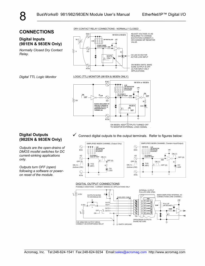
Connect digital outputs to the output terminals. Refer to figures below:
V
L
D
A
A
B ON
V
V
OUT3OUT2
OUT1
15 CH03
14 CH02
12 CH00
11 EXC +5V
0-35V D
OUT0
L
TB1
16 RTN
13 CH01
TB1
DIG
ITA
L IN
or O
UT
SHIELDED CABLE
OFF
0-35V
OUTPUTS RATEDTO 35V/500mA DC
EARTH GROUND
5.6K
100K
FOR GREATER OUTPUT DRIVE,CONNECT AN INTERPOSING RELAY
INTERNAL OUTPUTPULLUPS ARE OPEN
OPEN-DRAIN OUTPUTSSHARE RETURN
PULLUP(IN SOCKET)
983EN SIMPLIFIED INTERNAL I/OCONNECTIONS (ONE CHANNEL)
DIGITAL OUTPUT CONNECTIONSPOSSIBLE VARIATIONS - CURRENT SINKING DC APPLICATIONS ONLY
CONNECTIONSDigital Inputs(981EN & 983EN Only)Normally Closed Dry ContactRelay.
Digital TTL Logic Monitor
Digital Outputs(982EN & 983EN Only)
Outputs are the open-drains ofDMOS mosfet switches for DCcurrent-sinking applicationsonly.
Outputs turn OFF (open)following a software or power-on reset of the module.
BusWorks® 981/982/983EN Module User’s Manual EtherNet/IP™ Digital I/O___________________________________________________________________
_______________________________________________________________________________________Acromag, Inc. Tel:248-624-1541 Fax:248-624-9234 Email:[email protected] http://www.acromag.com
9
CH
V
+5V
ON
RTN
5.6K
100K OFF
983EN
I/O
EXC
TO OTHER 3CHAN OF PORT
OFF
R5-35V
1N4006
RELAY COIL/SOLENOID DRIVER
ON
SIP RESISTORINSTALLEDIN SOCKET
982EN/983EN
V
ON
R
100K
5.6K
CH
OFF
5-35V I/O
EXC
OFF
ON
+5V
983EN
SIP RESISTORINSTALLEDIN SOCKET
RTN
982EN/983EN
TO OTHER 3CHAN OF PORT
INCANDESCENT LAMP CONTROL
V
ON
R
100K
5.6K
CH TOLOAD/LINE
LED ON
+5VR
RTN
982EN/983EN
OFF
I/O
(N.O.)SSR
EXC TOLOAD/LINE
OFF
TO OTHER 3CHAN OF PORT
983EN
SIP RESISTORINSTALLEDIN SOCKET
SOLID-STATE RELAY (SSR) OR LED DRIVER
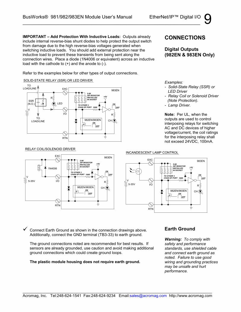
IMPORTANT – Add Protection With Inductive Loads: Outputs alreadyinclude internal reverse-bias shunt diodes to help protect the output switchfrom damage due to the high reverse-bias voltages generated whenswitching inductive loads. You should add external protection near theinductive load to prevent these transients from being sent along theconnection wires. Place a diode (1N4006 or equivalent) across an inductiveload with the cathode to (+) and the anode to (-).
Refer to the examples below for other types of output connections.
Connect Earth Ground as shown in the connection drawings above.Additionally, connect the GND terminal (TB3-33) to earth ground.
The ground connections noted are recommended for best results. Ifsensors are already grounded, use caution and avoid making additionalground connections which could create ground loops.
The plastic module housing does not require earth ground.
CONNECTIONS
Digital Outputs(982EN & 983EN Only)
Examples:- Solid-State Relay (SSR) or LED Driver- Relay Coil or Solenoid Driver
(Note Protection).- Lamp Driver.
Note: Per UL, when theoutputs are used to controlinterposing relays for switchingAC and DC devices of highervoltage/current, the coil ratingsfor the interposing relay shallnot exceed 24VDC, 100mA.
Earth Ground
Warning: To comply withsafety and performancestandards, use shielded cableand connect earth ground asnoted. Failure to use goodwiring and grounding practicesmay be unsafe and hurtperformance.

BusWorks® 981/982/983EN Module User’s Manual EtherNet/IP™ Digital I/O__________________________________________________________________
_______________________________________________________________________________________Acromag, Inc. Tel:248-624-1541 Fax:248-624-9234 Email:[email protected] http://www.acromag.com
10This module supports EtherNet/IP and Modbus TCP/IP. You may use yourown method to issue EtherNet/IP or Modbus commands to this module asrequired, or you may use a standard web browser, as these modules havebuilt-in web pages that allow you to setup and control the module. Simplyexecute your web browser, type the IP address assigned to your module inthe “Address” window (http://128.1.1.100/ for our example), click [Go], andyou will be presented with a Home Page window similar to that shown below:
The Home Page provides buttons to access the other web pages of thismodule that are used to configure the network parameters, change the username and password, and operate the module. For each new browsersession that accesses the Home Page of this module, you will be presentedwith a window prompting you to enter the current User Name and Passwordas shown below. This information is required before the program will allowyou to make any other selections. The default user name and passwordis “User” and “password00” respectively. After entering these defaults,you may wish to invoke the Password Configuration Page to change theseparameters to something more meaningful for you.
IMPORTANT: If you forget youruser name and password, youcan always toggle the moduleinto default mode via the defaultmode toggle switch at the frontof the module, and thepassword and username willrevert to the original defaultsnoted above, thus allowing youto re-invoke the PasswordConfiguration Page and changethe username and password asrequired.
WEB BROWSER
Home Page
BusWorks® 981/982/983EN Module User’s Manual EtherNet/IP™ Digital I/O___________________________________________________________________
_______________________________________________________________________________________Acromag, Inc. Tel:248-624-1541 Fax:248-624-9234 Email:[email protected] http://www.acromag.com
11
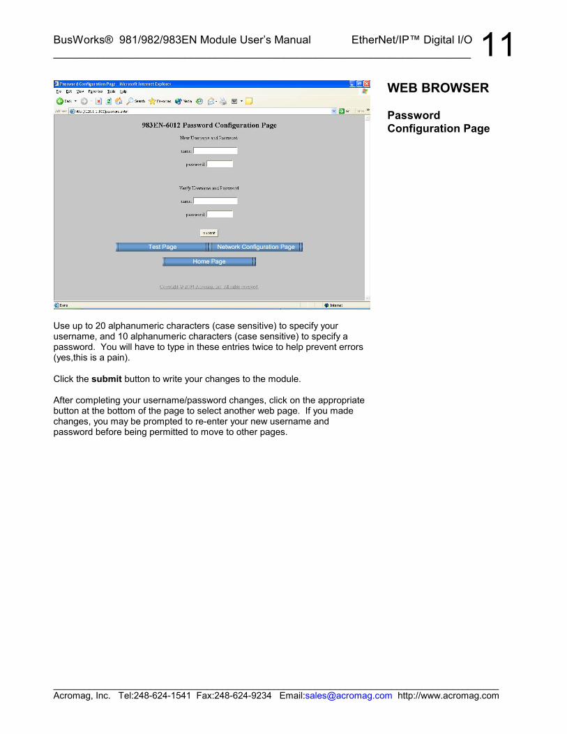
Use up to 20 alphanumeric characters (case sensitive) to specify yourusername, and 10 alphanumeric characters (case sensitive) to specify apassword. You will have to type in these entries twice to help prevent errors(yes,this is a pain).
Click the submit button to write your changes to the module.
After completing your username/password changes, click on the appropriatebutton at the bottom of the page to select another web page. If you madechanges, you may be prompted to re-enter your new username andpassword before being permitted to move to other pages.
WEB BROWSER
PasswordConfiguration Page
BusWorks® 981/982/983EN Module User’s Manual EtherNet/IP™ Digital I/O__________________________________________________________________
_______________________________________________________________________________________Acromag, Inc. Tel:248-624-1541 Fax:248-624-9234 Email:[email protected] http://www.acromag.com
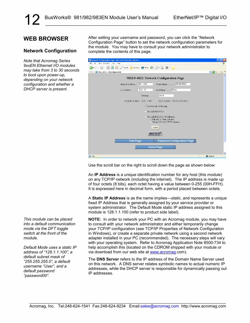
12After setting your username and password, you can click the “NetworkConfiguration Page” button to set the network configuration parameters forthe module. You may have to consult your network administrator tocomplete the contents of this page.
Use the scroll bar on the right to scroll down the page as shown below:
An IP Address is a unique identification number for any host (this module)on any TCP/IP network (including the internet). The IP address is made upof four octets (8 bits), each octet having a value between 0-255 (00H-FFH).It is expressed here in decimal form, with a period placed between octets.
A Static IP Address is as the name implies—static, and represents a uniquefixed IP Address that is generally assigned by your service provider orsystem administrator. The Default Mode static IP address assigned to thismodule is 128.1.1.100 (refer to product side label).
NOTE: In order to network your PC with an Acromag module, you may haveto consult with your network administrator and either temporarily changeyour TCP/IP configuration (see TCP/IP Properties of Network Configurationin Windows), or create a separate private network using a second networkadapter installed in your PC (recommended). The necessary steps will varywith your operating system. Refer to Acromag Application Note 8500-734 tohelp accomplish this (located on the CDROM shipped with your module orvia download from our web site at www.acromag.com).
The DNS Server refers to the IP address of the Domain Name Server usedon this network. A DNS server relates symbolic names to actual numeric IPaddresses, while the DHCP server is responsible for dynamically passing outIP addresses.
WEB BROWSER
Network Configuration
Note that Acromag Series9xxEN Ethernet I/O modulesmay take from 3 to 30 secondsto boot upon power-up,depending on your networkconfiguration and whether aDHCP server is present.
This module can be placedinto a default communicationmode via the DFT toggleswitch at the front of themodule.
Default Mode uses a static IPaddress of “128.1.1.100”, adefault subnet mask of“255.255.255.0”, a defaultusername “User”, and adefault password“password00”.
BusWorks® 981/982/983EN Module User’s Manual EtherNet/IP™ Digital I/O___________________________________________________________________
_______________________________________________________________________________________Acromag, Inc. Tel:248-624-1541 Fax:248-624-9234 Email:[email protected] http://www.acromag.com
13A Subnet Mask is used to subdivide the host portion of the IP address intotwo or more subnets. The subnet mask will flag the bits of the IP addressthat belong to the network address, and the remaining bits correspond to thehost portion of the address. The unique subnet to which an IP addressrefers to is recovered by performing a bitwise AND operation between the IPaddress and the mask itself, with the result being the sub-network address.
Gateway refers to the IP Address of the gateway, if your local area networkhappens to be isolated by a gateway. Typically, it is assigned the first hostaddress in the subnet. If a gateway is not present, then this field shouldcontain an unused address within the host subnet address range.
The Host Name is the name to be assigned to this host if its addresshappens to be assigned dynamically using DHCP.
The Active IP Address refers to the current IP Address being used by thishost, as opposed to any new assignments being made via this page.
The MAC Address refers to the Media Access Control Address thatuniquely identifies the hardware of this device. This is a unique fixedaddress assigned to this module at the factory. In IEEE 802 networks, theData Link Control (DLC) layer of the OSI Reference Model is divided into twosublayers: the Logical Link Control (LLC) layer, and the Media AccessControl (MAC) layer. The MAC layer interfaces directly with the networkmedia (each different type of network media requires a different MAC layer).
By default, the module is setup to use Static IP Addressing and a Static IPAddress of 128.1.1.100. You can optionally choose to have the IP addressassigned dynamically via DHCP/BOOTP or DHCP/BOOTP w/Fallbacks.This will also require that you specify a valid Host Name. You can select“DHCP/BOOTP w/Fallback” and automatically revert to either a static IPaddress, or the last DHCP assigned IP address, if the DHCP or BOOTPserver cannot be found.
In general, BOOTP (BOOTstrap Protocol) refers to an internet protocol thatenables a diskless workstation to discover its own IP address, the address ofa BOOTP server on the network, and a file to be loaded into memory to bootthe machine. This enables the workstation or device server to boot withoutrequiring a hard or floppy disk drive. BOOTP works similar to DHCP, but isusually found in older systems. This protocol is defined by RFC 951.
DHCP refers to Dynamic Host Configuration Protocol and is a method usedto dynamically assign temporary numeric IP addresses as required. Withdynamic addressing, a device can have a different IP address every time itconnects to the network. In some systems, it can even change while it is stillconnected. In general, a DHCP server maintains a pool of shared IPaddresses which are dynamically assigned and recycled. When a DHCPdevice wants to use a TCP/IP application, it must request an IP addressfrom the DHCP server. The DHCP server will check the shared supply, andif all addresses are in use, the server will send a busy signal to the clientwhich tells it to try again later. Thus, although static IP addresses will ensurea connection every time, dynamic addresses will not.
WEB BROWSER
Network Configuration
BusWorks® 981/982/983EN Module User’s Manual EtherNet/IP™ Digital I/O__________________________________________________________________
_______________________________________________________________________________________Acromag, Inc. Tel:248-624-1541 Fax:248-624-9234 Email:[email protected] http://www.acromag.com
14DHCP also supports a combination of static and dynamic IP addresses. Youcan select “DHCP/BOOTP w/Fallback” and automatically revert to either astatic IP address, or the last DHCP assigned IP address, if the DHCP orBOOTP server cannot be found.
DNS refers to the Domain Name System or Domain Name Server and refersto the system used to associate an alphanumeric character string with anumeric IP address. The DNS is actually a distributed database of domainnames and corresponding IP addresses. These servers contain informationon some segment of the domain name space and make this informationavailable to clients called resolvers. For example, the DNS allows us to use“Acromag.com” as an IP address rather than a complicated number string.
The unit includes a default address toggle switch to cause the module toassume a fixed default static IP address (128.1.1.100). This switch is at thefront of the module and is used to toggle the module into, or out of DefaultMode. If you use the toggle switch at the front of the module to place themodule in default mode, then “Default Communications Mode” will beindicated at the bottom of this screen.
Click the Submit button to complete any changes made on this page.
Click the Wink On/Off button to toggle the module in/out of “wink” ID mode.In this mode, the module’s green RUN LED will blink to confirm identification.
You may refer to the following section to learn more about IP Addressingterms and concepts, or you can skip ahead to the Test Page.
A host is any device on any network. On TCP/IP networks, each host hasone or more unique IP addresses. This module connected to an Ethernetnetwork may be referred to as a host.
An IP Address is a unique identification number for any host (this module) onany TCP/IP network (including the internet). The IP address is made up offour octets (8 bits), each octet having a value between 0-255 (00H-FFH).
The IP address is comprised of two parts: the network address (first part)and the host address (last part). The number of octets of the four total thatbelong to the network address depend on the Class definition (see below).
A Static IP Address is as the name implies—static. That is, it is a unique IPAddress that is assigned by a service provider and never changes.
A Dynamic IP Address is an address that is temporarily assigned to a userby a service provider each time a user connects.
A Subnet is a contiguous string of IP addresses. The first IP address in asubnet is used to identify the subnet, while the last IP address in a subnet isalways used as a broadcast address. Anything sent to the last IP address ofa subnet is sent to every host on that subnet.
WEB BROWSER
Network Configuration
The Default CommunicationMode uses a static IP addressof “128.1.1.100”, a defaultsubnet mask of“255.255.255.0”, a defaultusername of “User”, and adefault password of“password00”.
Discussion Topic –IP Addressing
BusWorks® 981/982/983EN Module User’s Manual EtherNet/IP™ Digital I/O___________________________________________________________________
_______________________________________________________________________________________Acromag, Inc. Tel:248-624-1541 Fax:248-624-9234 Email:[email protected] http://www.acromag.com
15Subnets are further broken down into three size classes based on the 4octets that make up the IP address. A Class A subnet is any subnet thatshares the first octet of the IP address. The remaining 3 octets of a Class Asubnet will define up to 16,777,214 possible IP addresses (224 – 2). A ClassB subnet shares the first two octets of an IP address (providing 216 – 2, or65534 possible IP addresses). Class C subnets share the first 3 octets of anIP address, giving 254 possible IP addresses. Recall that the first and lastIP addresses are always used as a network number and broadcast addressrespectively, and this is why we subtract 2 from the total possible uniqueaddresses that are defined via the remaining octet(s).
For our example, the default IP address of this module is 128.1.1.100. If weassume that this is a Class C network address (based on the default ClassC subnet mask of 255.255.255.0), then the first three numbers represent thisClass C network at address 128.1.1.0, the last number identifies a uniquehost/node on this network (node 100) at address 128.1.1.100.
A Subnet Mask is used to determine which subnet an IP address belongs to.The use of a subnet mask allows the network administrator to further dividethe host part of this address into two or more subnets. The subnet maskflags the network address portion of the IP address, plus the bits of the hostpart that are used for identifying the sub-network. By convention, the bits ofthe mask that correspond to the sub-network address are all set to 1’s (itwould also work if the bits were set exactly as in the network address). It’scalled a mask because it can be used to identify the unique subnet to whichan IP address belongs to by performing a bitwise AND operation betweenthe mask itself, and the IP address, with the result being the subnetworkaddress, and the remaining bits the host or node address.
For our Example, if we wish to further divide this network into 14 subnets,then the first 4 bits of the host address will be required to identify thesubnetwork (0110), then we would use “11111111.11111111.11111111.11110000” as our subnet mask. This would effectively subdivide our ClassC network into 14 subnetworks of up to 14 possible nodes each.
With respect to the default settings of this module:Subnet Mask 255.255.255.0 (11111111.11111111.11111111.00000000)IP Address: 128.1.1.100 (10000000.00000001.00000001.01100100)Subnet Address: 128.1.1.0 (1000000.00000001.00000001.00000000)
The subnetwork address of 128.1.1.0 has 254 possible unique nodeaddresses (we are using node 100 of 254 possible). Nodes 0 (first node)and 10 are typically reserved for servers and may yield poor results if used.Node 255 (last node in the subnet) is reserved as a broadcast address forthe subnet.
Discussion Topic –IP Addressing
TIP: The first node (0) andnode 10 are typically reservedfor servers and may yield poorresults if used. The last nodeis reserved as a broadcastaddress for the subnet.
BusWorks® 981/982/983EN Module User’s Manual EtherNet/IP™ Digital I/O__________________________________________________________________
_______________________________________________________________________________________Acromag, Inc. Tel:248-624-1541 Fax:248-624-9234 Email:[email protected] http://www.acromag.com
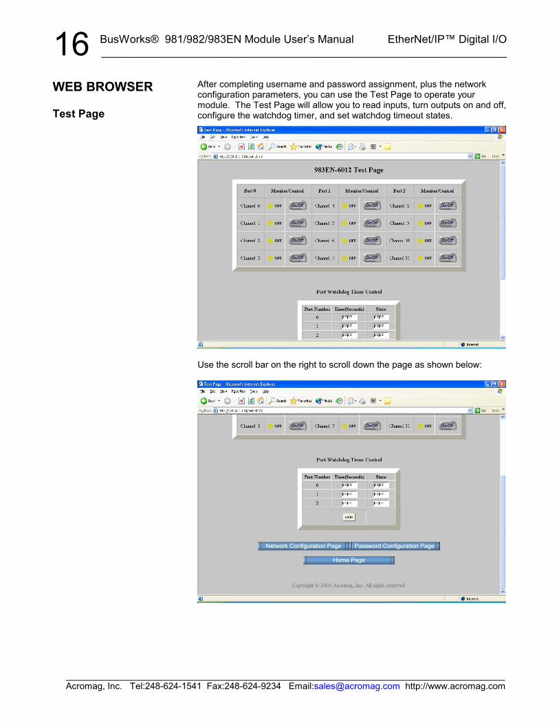
16After completing username and password assignment, plus the networkconfiguration parameters, you can use the Test Page to operate yourmodule. The Test Page will allow you to read inputs, turn outputs on and off,configure the watchdog timer, and set watchdog timeout states.
Use the scroll bar on the right to scroll down the page as shown below:
WEB BROWSER
Test Page

BusWorks® 981/982/983EN Module User’s Manual EtherNet/IP™ Digital I/O___________________________________________________________________
_______________________________________________________________________________________Acromag, Inc. Tel:248-624-1541 Fax:248-624-9234 Email:[email protected] http://www.acromag.com
17Note that the 12 channels of this module are divided into 3 groups (ports) of4 channels each. Each port represents one pluggable I/O terminal block (6screws). Port Number 0 refers to I/O channels 0-3, port number 1 refers tochannels 4-7, and port number 3 to channels 8-11. The state of a channel isindicated by the color of the simulated LED’s and the text “ON” or “OFF”.These states also reflect the actual yellow I/O status LED’s of the module.
IMPORTANT: The input state indication only reflects the state of the inputsat the moment this screen is invoked and this does not continuously update.You can click your browser’s refresh button to get a new input update. Theoutput states are updated each time you click the channel’s On/Off button.
You can use the On/Off buttons adjacent to the channel number to turn theoutputs of 982EN and 983EN modules ON or OFF. The output stateindication is updated each time you click On/Off.
A watchdog timeout is triggered at the port if no channel read or write occursfor one or more channels of a port within the time period specified. You canuse the Port watchdog Timer Control to specify Time from 0001H to FFFEHseconds (1 to 65534s). A Time value of 0000H or FFFFH (0 or 65535) willdisable the timer for the port I/O. You can also define the state the outputsare to assume following a timeout via the lower 4 bits of the 16-bit valueentered into the State field for the port. Enter FFFFH into the State field toleave the port outputs unchanged following a timeout. Note that the lowerorder bit (bit 0) corresponds to the lowest channel number for the port, bit 1to the next channel number, and so on. Except for FFFFH, the first threehexadecimal digits of State are ignored (each port has only 4 channels andthe least significant nibble (4-bits) of the State value are all that’s required forcontrol. For example, Enter a state value of “0000” to turn OFF (open) allport outputs (failsafe state) upon watchdog timeout. You would enter “000F”to turn all port outputs ON upon watchdog timeout.
Upon power-up, the green “Run” LED should light. This indicates the unit isoperating normally. A continuous blinking Run LED indicates “wink” IDmode. If the Run LED remains OFF and correct power has been applied,then either the internal power supply has failed or a fatal processor error(firmware) has occurred.
WEB BROWSER
Test Page
TIP: Viewing a module’s webpage is treated similar toviewing a web page on theinternet. The first time youopen a page, its image isstored as a temporary internetfile in PC memory. However,each subsequent attempt toview that page will need toautomatically update thatimage, especially whenmaking configuration changes.With Internet Explorer, clickthe “Internet Options” of the“Tools” menu, select the“General” tab, locate the“Temporary Internet Files”information and click on the“Settings” button. Then select“Automatically” under “Checkfor newer versions of storedpages:”. Then click [OK] toreturn to the “General” screen,and click [OK] again to saveyour settings.
TROUBLE-SHOOTING
BusWorks® 981/982/983EN Module User’s Manual EtherNet/IP™ Digital I/O__________________________________________________________________
_______________________________________________________________________________________Acromag, Inc. Tel:248-624-1541 Fax:248-624-9234 Email:[email protected] http://www.acromag.com
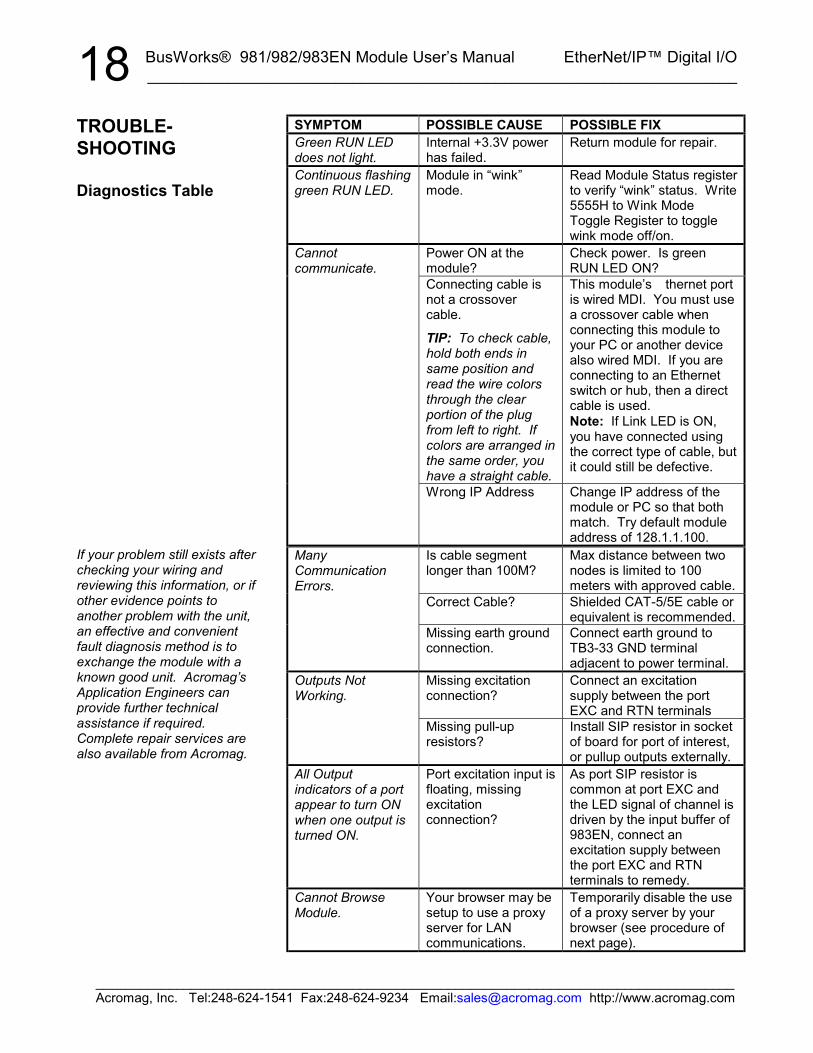
18SYMPTOM POSSIBLE CAUSE POSSIBLE FIXGreen RUN LEDdoes not light.
Internal +3.3V powerhas failed.
Return module for repair.
Continuous flashinggreen RUN LED.
Module in “wink”mode.
Read Module Status registerto verify “wink” status. Write5555H to Wink ModeToggle Register to togglewink mode off/on.
Cannotcommunicate.
Power ON at themodule?
Check power. Is greenRUN LED ON?
Connecting cable isnot a crossovercable.
TIP: To check cable,hold both ends insame position andread the wire colorsthrough the clearportion of the plugfrom left to right. Ifcolors are arranged inthe same order, youhave a straight cable.
This module’s thernet portis wired MDI. You must usea crossover cable whenconnecting this module toyour PC or another devicealso wired MDI. If you areconnecting to an Ethernetswitch or hub, then a directcable is used.Note: If Link LED is ON,you have connected usingthe correct type of cable, butit could still be defective.
Wrong IP Address Change IP address of themodule or PC so that bothmatch. Try default moduleaddress of 128.1.1.100.
ManyCommunicationErrors.
Is cable segmentlonger than 100M?
Max distance between twonodes is limited to 100meters with approved cable.
Correct Cable? Shielded CAT-5/5E cable orequivalent is recommended.
Missing earth groundconnection.
Connect earth ground toTB3-33 GND terminaladjacent to power terminal.
Outputs NotWorking.
Missing excitationconnection?
Connect an excitationsupply between the portEXC and RTN terminals
Missing pull-upresistors?
Install SIP resistor in socketof board for port of interest,or pullup outputs externally.
All Outputindicators of a portappear to turn ONwhen one output isturned ON.
Port excitation input isfloating, missingexcitationconnection?
As port SIP resistor iscommon at port EXC andthe LED signal of channel isdriven by the input buffer of983EN, connect anexcitation supply betweenthe port EXC and RTNterminals to remedy.
Cannot BrowseModule.
Your browser may besetup to use a proxyserver for LANcommunications.
Temporarily disable the useof a proxy server by yourbrowser (see procedure ofnext page).
TROUBLE-SHOOTING
Diagnostics Table
If your problem still exists afterchecking your wiring andreviewing this information, or ifother evidence points toanother problem with the unit,an effective and convenientfault diagnosis method is toexchange the module with aknown good unit. Acromag’sApplication Engineers canprovide further technicalassistance if required.Complete repair services arealso available from Acromag.
BusWorks® 981/982/983EN Module User’s Manual EtherNet/IP™ Digital I/O___________________________________________________________________
_______________________________________________________________________________________Acromag, Inc. Tel:248-624-1541 Fax:248-624-9234 Email:[email protected] http://www.acromag.com
19Please refer Acromag Application Note 8500-734 for help in setting upnetwork communication with your module (located on the CDROM shippedwith your module or via download from our web site at www.acromag.com).This document gives details for changing your PC’s TCP/IP configuration inorder to communicate with your module (see TCP/IP Properties of NetworkConfiguration in Windows).
If you have carefully followed this procedure and you still cannot browse yourmodule, you may have the web browser of your laptop or PC setup to use aproxy server when browsing the web. If you are using Internet Explorer,Refer to the “Tools” pulldown menu, select “Internet options…”, click the“Connections” tab, then click the “LAN Settings” button. Locate the Proxyserver information and uncheck the box next to the statement “Use a proxyserver for your LAN”. Then click [OK] to return to the “Connections” screen,and click [OK] again to save your settings.
You should now be able to use Internet Explorer to browse the module asrequired. However, to later restore your PC’s connection to your companynetwork, you may have to re-enable the use of a proxy server for your LAN.
There is no built-in error detection to prevent you from writing invalid valuesto a configuration register. As such, if you inadvertently write an invalidvalue to an internal register, you could cause the module to becomeinoperable under certain conditions. If this happens, in order to regaincontrol of the module, the module can either be re-downloaded at thefactory, or you can try restoring the module to its initial configuration byfollowing this procedure:
Procedure For Restoring any 9xxEN Module to its Initial Configuration
1. While module power is OFF, press and hold the front-panel toggleswitch in the default (DFT left) position.
2. While continuing to hold the toggle switch in the default position, applypower to the module.
3. After a few seconds, the Status LED will begin to blink quickly and youcan release the default switch at this point. The module will continue toboot itself as it normally does. That is, the green RUN LED will blink for1-10 seconds as the unit acquires its address, then remain ON fornormal operation.
4. If the STATUS LED fails to blink rapidly after a few seconds and theRUN LED just blinks for a few moments as it normally does, thenreinitializing the module has failed and you should try it again. Thistime, make sure that the DFT switch is completely depressed and heldwhile powering the unit. Also make sure that you are pressing the DFTtoggle in the DFT direction (left), rather than the RST direction (right).
TROUBLE-SHOOTING
Trouble Browsing YourModule?
Getting Out Of Trouble
So, your module’s “gone wild”,follow this procedure to restoreit to its initial configuration andregain control.
BusWorks® 981/982/983EN Module User’s Manual EtherNet/IP™ Digital I/O__________________________________________________________________
_______________________________________________________________________________________Acromag, Inc. Tel:248-624-1541 Fax:248-624-9234 Email:[email protected] http://www.acromag.com
20TECHNICAL REFERENCE• Safety Agency Approvals – CE, UL, & cUL listed, plus Class 1;
Division 2; Groups A, B, C, D approval.• Fully Isolated – I/O channels, network, and power are all isolated from
each other for safety and increased noise immunity.• EtherNet/IP Protocol Support – Supports up to 10 connected
messaging sessions, plus unconnected messaging. It also supportsPCCC messaging for legacy support with Allen Bradley SLC5/05 PLC’s.
• Built-In Web Server – Allows unit to optionally be configured, controlled,and monitored via access with a standard web browser over thernet.
• Modbus TCP/IP Protocol Support – Supports 1 socket of ModbusTCP/IP using port number 502.
• Flexible IP Addressing – Supports static, DHCP, or BOOTP. Unit mayalso fall back to last DHCP IP address assignment.
• Convenient “Wink” ID Mode Support – Blinks green RUN LED in winkmode as a tool to help identify specific remote units.
• Fully Independent w/ Direct I/O Connection – Self-contained with nospecial bus couplers, power supply, or rack mount required to operate.
• Network Port is Transient Protected – Shielded RJ45 port includestransient protection from ESD, EFT, and other transients.
• 10Base-T and 100Base-TX Support – Per IEEE 802.3/802.3u.• Auto-Negotiated 10/100Mbps, Half or Full Duplex.• Plug-In Terminal Blocks & DIN-Rail Mount – Make mounting,
removal, and replacement easy.• Flexible Discrete Inputs & Outputs – High voltage/current open-drain
outputs provide direct (low-side) control of external devices. Bufferedinputs allow outputs to be read back, or input levels to be monitored.
• Tandem Input/Output Circuitry (983EN Only) – Input buffers areconnected in tandem with open-drain outputs for convenient loop-backmonitoring of the output state.
• Convenient Pullup SIP Resistors Mounted In Sockets – Providesinput and output pull-ups to the excitation supply. These SIP resistorscan be removed or exchanged according to your application.
• Outputs Have Built-in Protection – Over-temperature/current shut-down protection & active clamping circuitry for switching inductive loads.
• Failsafe Mode Support w/Watchdog Time Control – Outputs can besent to a failsafe state if the host fails and a watchdog timeout occurs.
• Nonvolatile Reprogrammable Memory – Allows the functionality of thisdevice to be reliably reprogrammed thousands of times.
• Operation/Diagnostic LED Indicators Aide Troubleshooting – 12yellow LED’s indicate active-low I/O state. Yellow ACT LED indicatesport activity (busy). Green LNK LED indicates link (auto-negotiationcomplete and connection established). Green RUN LED indicatespower or blinks in wink ID mode. Yellow ST LED indicates defaultcommunication mode (slow flash) and timeout status (fast flash).
• Internal Hardware Watchdog Timer - Built into the microcontroller thatcauses it to initiate a self reset if the controller ever “locks up” or fails toreturn from an operation in a timely manner.
• Wide-Range DC-Power – Diode-coupled for use with redundantsupplies, and/or battery back-up.
• Hardened For Harsh Environments – For protection from RFI, EMI,ESD, EFT, & surges. Has low radiated emissions per CE requirements.
• Wide Ambient Operation – Reliable over a wide temperature range.
KEY FEATURES
BusWorks® 981/982/983EN Module User’s Manual EtherNet/IP™ Digital I/O___________________________________________________________________
_______________________________________________________________________________________Acromag, Inc. Tel:248-624-1541 Fax:248-624-9234 Email:[email protected] http://www.acromag.com
21
+5V
ON
PULLUPS
ON
100K OFF
RSTDEFA
STA
+3.3V
ACT
3.3V
LINK
+3.3V
6
3
I/OActiveLOW
EXC
TO OTHER3 CHAN OFPORT
5.6K
OFF
R(982EN)
CH
+3.3V
or R(981EN)(983EN)
CLK32K
5V
78
124 RJ45
RTN
15-36VDC
5
POWER
RUN
+3.3V+3.3V
+3.3V
DC-
GND
982EN/983ENOUTPUT BLOCK
OPEN-DRAIN OUTPUT
5.6K OHM SIP RESISTORINSTALLED IN SOCKET
I/OPOWERTOGGLE
SWITCH
RTC
MICRO-CONTROLLER
ISOLATEDFLYBACKSWITCHER
VRAM
DC+
SIMPLIFIED SCHEMATIC(1 CHANNEL OF 12)
I/O LOGICPOWER
Ethernet Port IncludesESD Protection
BUFFERED INPUT
ISOLATED ETHERNET
I/O STATUS LED
ISOLATED INPUT POWER
SRAM(512Kx8)
ETHERNETCONTROLLER
981EN/983EN INPUT BLOCK
983EN SIMPLIFIED SCHEMATIC
FLASH(512Kx8)
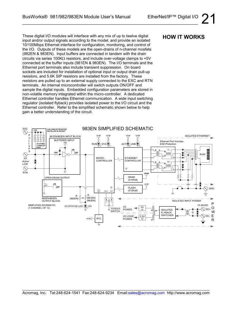
These digital I/O modules will interface with any mix of up to twelve digitalinput and/or output signals according to the model, and provide an isolated10/100Mbps Ethernet interface for configuration, monitoring, and control ofthe I/O. Outputs of these models are the open-drains of n-channel mosfets(982EN & 983EN). Input buffers are connected in tandem with the draincircuits via series 100KΩ resistors, and include over-voltage clamps to +5Vconnected at the buffer inputs (981EN & 983EN). The I/O terminals and theEthernet port terminals also include transient suppression. On boardsockets are included for installation of optional input or output drain pull-upresistors, and 5.6K SIP resistors are installed from the factory. Theseresistors are pulled up to an external supply connected to the EXC and RTNterminals. An internal microcontroller will switch outputs ON/OFF andsample the digital inputs. Embedded configuration parameters are stored innon-volatile memory integrated within the micro-controller. A dedicatedEthernet controller handles Ethernet communication. A wide input switchingregulator (isolated flyback) provides isolated power to the I/O circuit and theEthernet controller. Refer to the simplified schematic shown below to helpgain a better understanding of the circuit.
HOW IT WORKS
BusWorks® 981/982/983EN Module User’s Manual EtherNet/IP™ Digital I/O__________________________________________________________________
_______________________________________________________________________________________Acromag, Inc. Tel:248-624-1541 Fax:248-624-9234 Email:[email protected] http://www.acromag.com
22EtherNet/IP (Ethernet Industrial Protocol) is traditional Ethernet combinedwith an industrial application layer protocol targeted to industrial automation.This application layer protocol is the Control and Information Protocol(CIP™).
For more information on EtherNet/IP, please refer to our whitepaper“Introduction to EtherNet/IP”, 8500-747. This document is included on theCDROM that came with your module and may also be downloaded from ourweb site at www.acromag.com. You may also obtain a copy of theEtherNet/IP standard from the Open deviceNet Vendor association (ODVA)web site for EtherNet/IP at www.ethernet-ip.org.
All CIP™ devices are modeled as a collection of objects. An objectrepresents a particular component of a device. This collection of relateddata values and common elements of the device make up its object model.We use the term class to refer to a specific type or set of objects (same kindof system components), and instance to refer to one implementation of aclass. The term attribute refers to a characteristic of an instance, an object,or an object class. Attributes provide status information and govern theoperation of an object. Services are used to trigger the object/class toperform a task. And the object’s response is referred to as its behavior.Note that the term object and class are often used interchangeably, eventhough a class is really a specific type of object.
To illustrate, if our object is fruit, we can say that an apple is a class of fruit.A Macintosh apple is an instance of this class, and red skin is one attributeof this particular instance.
In general, there are three types of objects or classes defined by CIP™—required objects, application or device-specific objects, and vendor-specificobjects. Required objects must be included in every CIP™ device. Device-specific objects are the objects that define the data encapsulated by thedevice and are specific to the type of device and its function. Objects notfound in the profile for a device class are vendor-specific objects and thesevendor extensions are usually included as additional features of the device.
With CIP™, a class exists simply to combine data for I/O messaging amongcommon elements and the CIP™ library already contains many commonlydefined objects or classes. The confusion that surrounds this topic usuallyarises from the nesting of objects and classes that occurs in defining otherobjects and classes, and in linking together these various objects to buildlarger device profiles. This device’s object model makes use of the followingobjects (any object ID from 64H to C7H is a vendor-specific object type):
OBJECT (ID) TYPEIdentity (01H) RequiredMessage Router (02H) RequiredAssembly (04H) RequiredConnection Manager (06H) RequiredTCP (F5H) RequiredEthernet Link (F6H) RequiredPCCC Object (67H) Vendor-specificDiscrete Input Data (70H) Vendor-specificDiscrete Output Data (71H) Vendor-specific
ETHERNET/IP
Object Models
BusWorks® 981/982/983EN Module User’s Manual EtherNet/IP™ Digital I/O___________________________________________________________________
_______________________________________________________________________________________Acromag, Inc. Tel:248-624-1541 Fax:248-624-9234 Email:[email protected] http://www.acromag.com
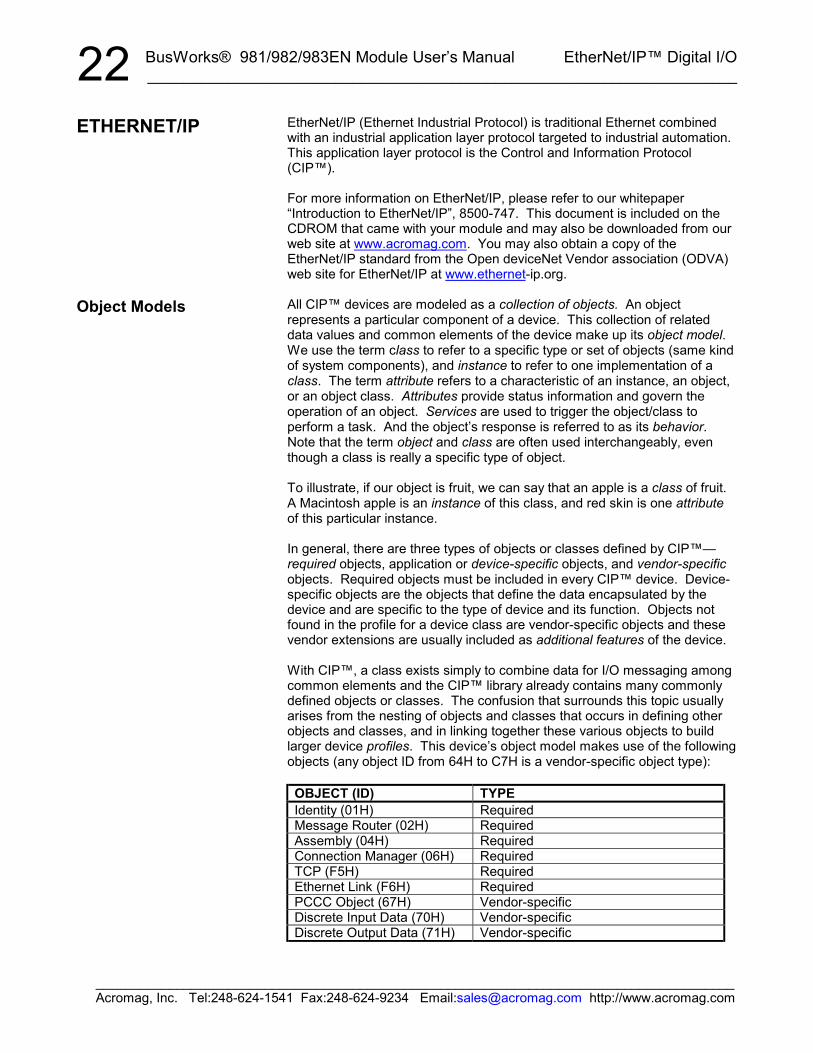
23The objects that follow form the object model for the 983EN-6012. Note thatthese objects make use of the following data types:
DATA TYPE DESCRIPTIONUSINT Unsigned Short Integer (8-bits)UINT Unsigned Integer (16-bits)UDINT Unsigned Double Integer (32-bits)STRING Character String w/ 1-byte per characterBYTE 8-bit StringWORD 16-bit StringDWORD 32-bit String
ATTR ID NAMEDATATYPE
DATAVALUE
ACCESSRULE
Class Attributes1 Revision UINT 1 GET
Instance Attributes1 Vendor Number UINT 894DEC GET2 Device Type 0x00 –
GenericUINT 00HEX GET
3 Product Code Number1 UINT 0EHEX(983EN)1
GET
4 Product Major RevisionProduct Minor Revision
USINTUSINT
0101
GET
5 Status Word (seedefinition below)
WORD See Below GET
6 Product Serial Number UDINT Unique 32Bit Value
GET
7 Product Name2
Structure of: Product Name Size Product Name String2
USINTUSINT[0-32]
18“Acromag983EN-6012”
GET
Status WordBit Bit = 0 Bit = 10 No I/O Connection I/O Connection Allocated
1-15 Unused UnusedCommon Services
SVC IMPLEMENTED FORCODE CLASS LEVEL INSTANCE LEVEL SERVICE NAME0EHEX Yes Yes Get_Attribute_Single05HEX No Yes Reset
Reset Service CodeSVCCODE CLASS INSTANCE ATTRIB DESCRIPTION0x05 0x01 0x01 0x003 Force software reset.0x05 0x01 0x01 0x013 Reload factory settings and
reset.1 Product Codes: 981EN=12 (0CH), 982EN=13 (0DH), or 983EN=14 (0EH).2 Product Name: “Acromag 981EN-6012”, “Acromag 982EN-6012”, or
“Acromag 983EN-6012”. 3Some software packages will require that theattribute field be left blank and this value entered in data field.
Object Models
Identity Object(01HEX – 1 Instance)
This object providesidentification of, and generalinformation about the device.
BusWorks® 981/982/983EN Module User’s Manual EtherNet/IP™ Digital I/O__________________________________________________________________
_______________________________________________________________________________________Acromag, Inc. Tel:248-624-1541 Fax:248-624-9234 Email:[email protected] http://www.acromag.com
24This object has no supported attributes.
ATTR ID NAMEDATATYPE
DATAVALUE
ACCESSRULE
Class Attributes1 Revision UINT 1 GET2 Max Instance UINT 81 GET
Instance 64H Attributes (Input Instance 1)3 Discrete Input Data
(Array of Words)UINT[ ] 1
0 982ENGET
Analog Input Data(Array of Words)
UINT[ ] 0
Instance 70H Attributes (Output Instance 1)3 Discrete Output Data
(Array of Words)UINT[ ] 1
0 981ENGET/SET
Analog Output Data(Array of Words)
UINT[ ] 0
Instance 80H Attributes (Configuration Instance)Most I/O clients include a Configuration path when opening an I/Oconnection to a server. There is no Configuration data needed.
Instance 81H Attributes (Heartbeat Instance – Input Only)This instance allows clients to monitor input data without providingoutput data.
Common ServicesSVC IMPLEMENTED FOR
CODE CLASS LEVEL INSTANCE LEVEL SERVICE NAME0EHEX Yes Yes Get_Attribute_Single10HEX No Yes Set_Attribute_Single
This object has no attributes.
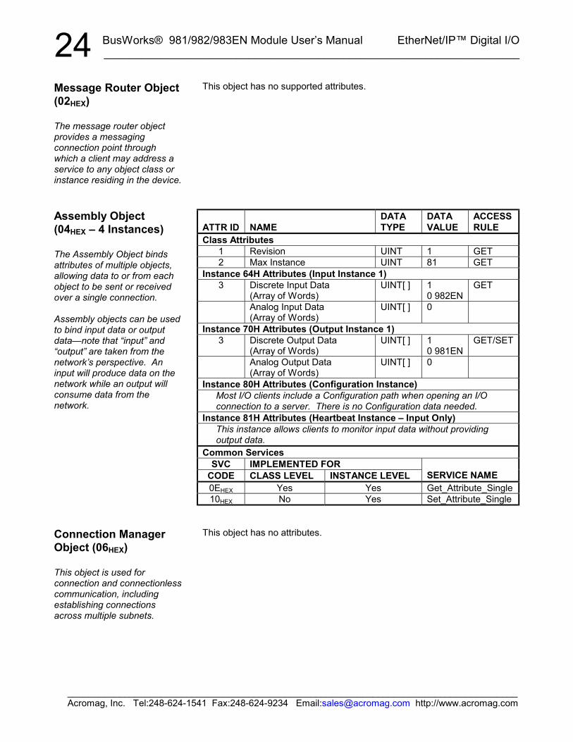
Message Router Object(02HEX)
The message router objectprovides a messagingconnection point throughwhich a client may address aservice to any object class orinstance residing in the device.
Assembly Object(04HEX – 4 Instances)
The Assembly Object bindsattributes of multiple objects,allowing data to or from eachobject to be sent or receivedover a single connection.
Assembly objects can be usedto bind input data or outputdata—note that “input” and“output” are taken from thenetwork’s perspective. Aninput will produce data on thenetwork while an output willconsume data from thenetwork.
Connection ManagerObject (06HEX)
This object is used forconnection and connectionlesscommunication, includingestablishing connectionsacross multiple subnets.
BusWorks® 981/982/983EN Module User’s Manual EtherNet/IP™ Digital I/O___________________________________________________________________
_______________________________________________________________________________________Acromag, Inc. Tel:248-624-1541 Fax:248-624-9234 Email:[email protected] http://www.acromag.com
25ATTR ID NAME
DATATYPE
DATAVALUE
ACCESSRULE
Class Attributes1 Revision UINT 1 GET
Instance1 Status1 DWORD 1 GET2 Configuration Capability2 DWORD 5 GET3 Configuration Control3 DWORD 0 GET
Physical Link Object4 -A Structure Of:
Path Size UINT 2
4
Path Array ofWORD
20F6H..2401H
GET
Interface Configuration5
A Structure Of:IP Address UDINT 0Network Mask UDINT 0Gateway Address UDINT 0Name Server UDINT 0Name Server 2 UDINT 0Domain Name Size UINT 0
5
Domain Name STRING 0
GET
Host Name6 -A Structure Of:
Host Name Size UINT 0
6
Host Name STRING 0
GET
Common ServicesSVC IMPLEMENTED FOR
CODE CLASS LEVEL INSTANCE LEVEL SERVICE NAME0EHEX Yes Yes Get_Attribute_Single10HEX No Yes Set_Attribute_Single
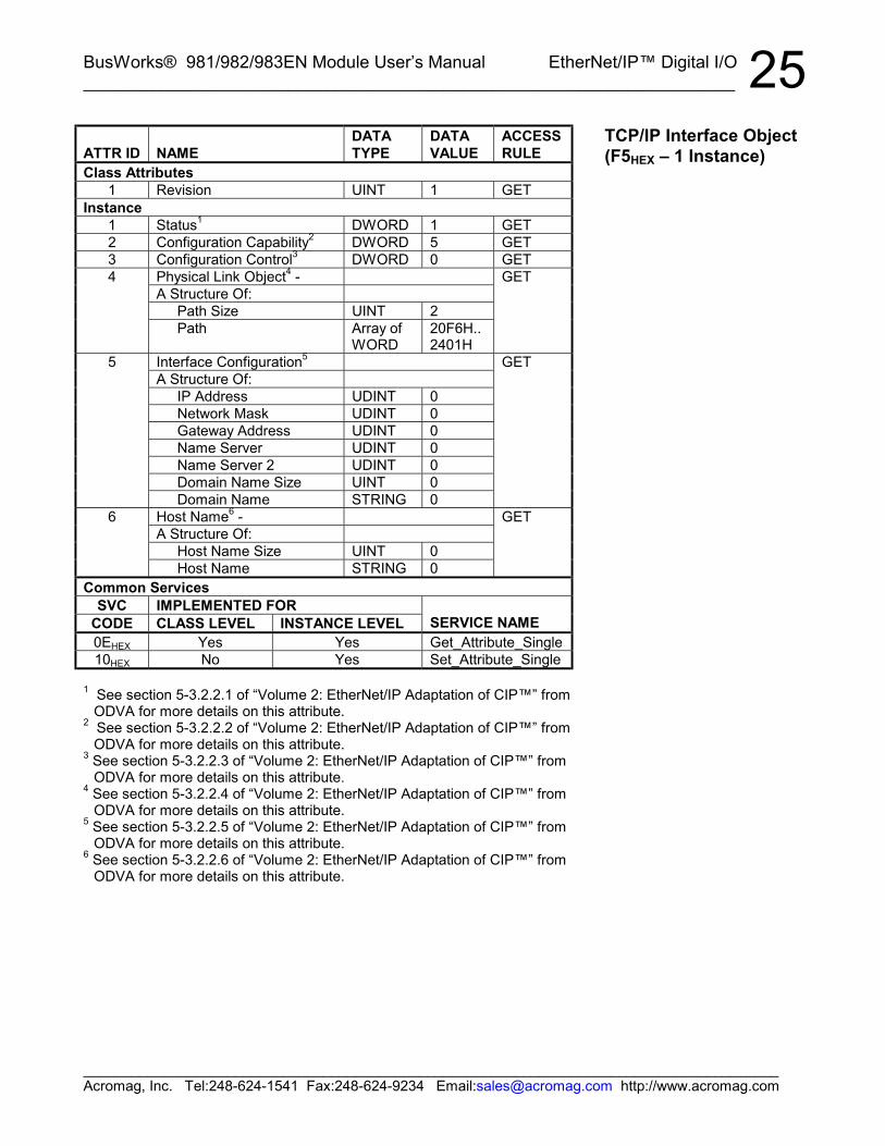
1 See section 5-3.2.2.1 of “Volume 2: EtherNet/IP Adaptation of CIP™” fromODVA for more details on this attribute.
2 See section 5-3.2.2.2 of “Volume 2: EtherNet/IP Adaptation of CIP™” fromODVA for more details on this attribute.
3 See section 5-3.2.2.3 of “Volume 2: EtherNet/IP Adaptation of CIP™” fromODVA for more details on this attribute.
4 See section 5-3.2.2.4 of “Volume 2: EtherNet/IP Adaptation of CIP™” fromODVA for more details on this attribute.
5 See section 5-3.2.2.5 of “Volume 2: EtherNet/IP Adaptation of CIP™” fromODVA for more details on this attribute.
6 See section 5-3.2.2.6 of “Volume 2: EtherNet/IP Adaptation of CIP™” fromODVA for more details on this attribute.
TCP/IP Interface Object(F5HEX – 1 Instance)

BusWorks® 981/982/983EN Module User’s Manual EtherNet/IP™ Digital I/O__________________________________________________________________
_______________________________________________________________________________________Acromag, Inc. Tel:248-624-1541 Fax:248-624-9234 Email:[email protected] http://www.acromag.com
26ATTR ID NAME
DATATYPE
DATAVALUE
ACCESSRULE
Class Attributes1 Revision UINT 1 GET
Instance Attributes1 Interface Speed1 UDINT 100
(default)GET
2 Interface Flags2 DWORD 3(default)
GET
3 Physical Address3 USINTArray[6]
0(default)
GET
Common ServicesSVC IMPLEMENTED FOR
CODE CLASS LEVEL INSTANCE LEVEL SERVICE NAME0EHEX Yes Yes Get_Attribute_Single
1 See section 5-4.2.2.2 of “Volume 2: EtherNet/IP Adaptation of CIP™” fromODVA for more details on this attribute.
2 See section 5-4.2.2.1 of “Volume 2: EtherNet/IP Adaptation of CIP™” fromODVA for more details on this attribute.
3 See section 5-4.2.2.3 of “Volume 2: EtherNet/IP Adaptation of CIP™” fromODVA for more details on this attribute.
EtherNet Link Object(F6HEX – 1 Instance)
BusWorks® 981/982/983EN Module User’s Manual EtherNet/IP™ Digital I/O___________________________________________________________________
_______________________________________________________________________________________Acromag, Inc. Tel:248-624-1541 Fax:248-624-9234 Email:[email protected] http://www.acromag.com
27ATTR ID NAME
DATATYPE
DATAVALUE
ACCESSRULE
Class Attributes – NONEInstance Attributes – NONECommon Services
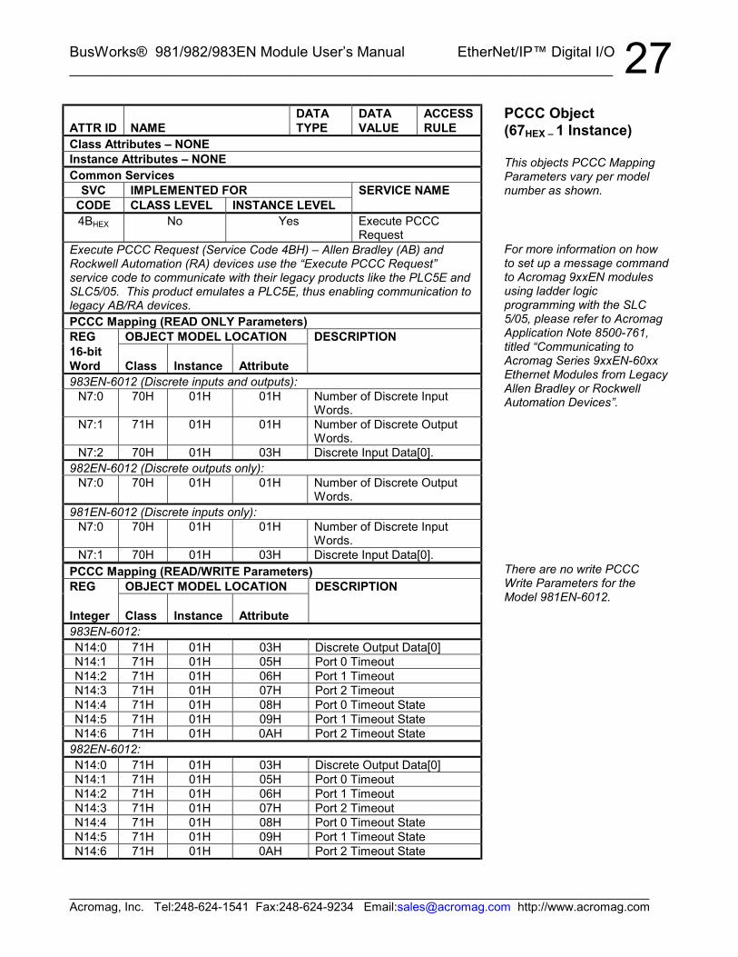
SVC IMPLEMENTED FOR SERVICE NAMECODE CLASS LEVEL INSTANCE LEVEL4BHEX No Yes Execute PCCC
RequestExecute PCCC Request (Service Code 4BH) – Allen Bradley (AB) andRockwell Automation (RA) devices use the “Execute PCCC Request”service code to communicate with their legacy products like the PLC5E andSLC5/05. This product emulates a PLC5E, thus enabling communication tolegacy AB/RA devices.PCCC Mapping (READ ONLY Parameters)REG OBJECT MODEL LOCATION DESCRIPTION16-bitWord Class Instance Attribute983EN-6012 (Discrete inputs and outputs):
N7:0 70H 01H 01H Number of Discrete InputWords.
N7:1 71H 01H 01H Number of Discrete OutputWords.
N7:2 70H 01H 03H Discrete Input Data[0].982EN-6012 (Discrete outputs only):
N7:0 70H 01H 01H Number of Discrete OutputWords.
981EN-6012 (Discrete inputs only):N7:0 70H 01H 01H Number of Discrete Input
Words.N7:1 70H 01H 03H Discrete Input Data[0].
PCCC Mapping (READ/WRITE Parameters)REG OBJECT MODEL LOCATION DESCRIPTION
Integer Class Instance Attribute983EN-6012:N14:0 71H 01H 03H Discrete Output Data[0]N14:1 71H 01H 05H Port 0 TimeoutN14:2 71H 01H 06H Port 1 TimeoutN14:3 71H 01H 07H Port 2 TimeoutN14:4 71H 01H 08H Port 0 Timeout StateN14:5 71H 01H 09H Port 1 Timeout StateN14:6 71H 01H 0AH Port 2 Timeout State
982EN-6012:N14:0 71H 01H 03H Discrete Output Data[0]N14:1 71H 01H 05H Port 0 TimeoutN14:2 71H 01H 06H Port 1 TimeoutN14:3 71H 01H 07H Port 2 TimeoutN14:4 71H 01H 08H Port 0 Timeout StateN14:5 71H 01H 09H Port 1 Timeout StateN14:6 71H 01H 0AH Port 2 Timeout State
PCCC Object(67HEX – 1 Instance)
This objects PCCC MappingParameters vary per modelnumber as shown.
For more information on howto set up a message commandto Acromag 9xxEN modulesusing ladder logicprogramming with the SLC5/05, please refer to AcromagApplication Note 8500-761,titled “Communicating toAcromag Series 9xxEN-60xxEthernet Modules from LegacyAllen Bradley or RockwellAutomation Devices”.
There are no write PCCCWrite Parameters for theModel 981EN-6012.
BusWorks® 981/982/983EN Module User’s Manual EtherNet/IP™ Digital I/O__________________________________________________________________
_______________________________________________________________________________________Acromag, Inc. Tel:248-624-1541 Fax:248-624-9234 Email:[email protected] http://www.acromag.com
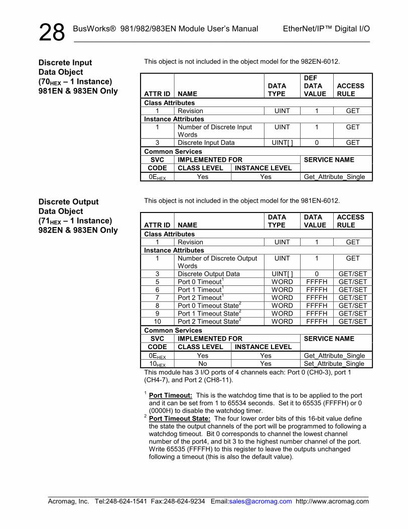
28This object is not included in the object model for the 982EN-6012.
ATTR ID NAMEDATATYPE
DEFDATAVALUE
ACCESSRULE
Class Attributes1 Revision UINT 1 GET
Instance Attributes1 Number of Discrete Input
WordsUINT 1 GET
3 Discrete Input Data UINT[ ] 0 GETCommon Services
SVC IMPLEMENTED FORCODE CLASS LEVEL INSTANCE LEVEL
SERVICE NAME
0EHEX Yes Yes Get_Attribute_Single
This object is not included in the object model for the 981EN-6012.
ATTR ID NAMEDATATYPE
DATAVALUE
ACCESSRULE
Class Attributes1 Revision UINT 1 GET
Instance Attributes1 Number of Discrete Output
WordsUINT 1 GET
3 Discrete Output Data UINT[ ] 0 GET/SET5 Port 0 Timeout1 WORD FFFFH GET/SET6 Port 1 Timeout1 WORD FFFFH GET/SET7 Port 2 Timeout1 WORD FFFFH GET/SET8 Port 0 Timeout State2 WORD FFFFH GET/SET9 Port 1 Timeout State2 WORD FFFFH GET/SET10 Port 2 Timeout State2 WORD FFFFH GET/SET
Common ServicesSVC IMPLEMENTED FOR
CODE CLASS LEVEL INSTANCE LEVELSERVICE NAME
0EHEX Yes Yes Get_Attribute_Single10HEX No Yes Set_Attribute_Single
This module has 3 I/O ports of 4 channels each: Port 0 (CH0-3), port 1(CH4-7), and Port 2 (CH8-11).
1 Port Timeout: This is the watchdog time that is to be applied to the portand it can be set from 1 to 65534 seconds. Set it to 65535 (FFFFH) or 0(0000H) to disable the watchdog timer.
2 Port Timeout State: The four lower order bits of this 16-bit value definethe state the output channels of the port will be programmed to following awatchdog timeout. Bit 0 corresponds to channel the lowest channelnumber of the port4, and bit 3 to the highest number channel of the port.Write 65535 (FFFFH) to this register to leave the outputs unchangedfollowing a timeout (this is also the default value).
Discrete InputData Object(70HEX – 1 Instance)981EN & 983EN Only
Discrete OutputData Object(71HEX – 1 Instance)982EN & 983EN Only
BusWorks® 981/982/983EN Module User’s Manual EtherNet/IP™ Digital I/O___________________________________________________________________
_______________________________________________________________________________________Acromag, Inc. Tel:248-624-1541 Fax:248-624-9234 Email:[email protected] http://www.acromag.com
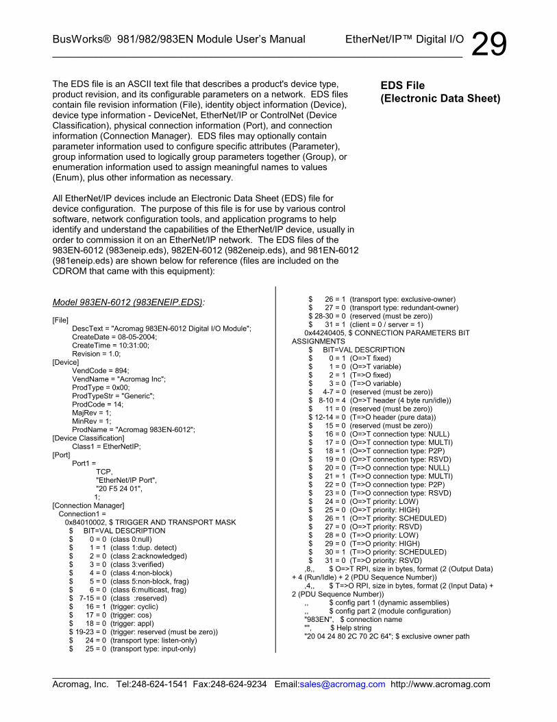
29The EDS file is an ASCII text file that describes a product's device type,product revision, and its configurable parameters on a network. EDS filescontain file revision information (File), identity object information (Device),device type information - DeviceNet, EtherNet/IP or ControlNet (DeviceClassification), physical connection information (Port), and connectioninformation (Connection Manager). EDS files may optionally containparameter information used to configure specific attributes (Parameter),group information used to logically group parameters together (Group), orenumeration information used to assign meaningful names to values(Enum), plus other information as necessary.
All EtherNet/IP devices include an Electronic Data Sheet (EDS) file fordevice configuration. The purpose of this file is for use by various controlsoftware, network configuration tools, and application programs to helpidentify and understand the capabilities of the EtherNet/IP device, usually inorder to commission it on an EtherNet/IP network. The EDS files of the983EN-6012 (983eneip.eds), 982EN-6012 (982eneip.eds), and 981EN-6012(981eneip.eds) are shown below for reference (files are included on theCDROM that came with this equipment):
Model 983EN-6012 (983ENEIP.EDS):
[File]DescText = "Acromag 983EN-6012 Digital I/O Module";CreateDate = 08-05-2004;CreateTime = 10:31:00;Revision = 1.0;
[Device]VendCode = 894;VendName = "Acromag Inc";ProdType = 0x00;ProdTypeStr = "Generic";ProdCode = 14;MajRev = 1;MinRev = 1;ProdName = "Acromag 983EN-6012";
[Device Classification]Class1 = EtherNetIP;
[Port]Port1 =
TCP, "EtherNet/IP Port", "20 F5 24 01", 1;[Connection Manager] Connection1 = 0x84010002, $ TRIGGER AND TRANSPORT MASK $ BIT=VAL DESCRIPTION $ 0 = 0 (class 0:null) $ 1 = 1 (class 1:dup. detect) $ 2 = 0 (class 2:acknowledged) $ 3 = 0 (class 3:verified) $ 4 = 0 (class 4:non-block) $ 5 = 0 (class 5:non-block, frag) $ 6 = 0 (class 6:multicast, frag) $ 7-15 = 0 (class :reserved) $ 16 = 1 (trigger: cyclic) $ 17 = 0 (trigger: cos) $ 18 = 0 (trigger: appl) $ 19-23 = 0 (trigger: reserved (must be zero)) $ 24 = 0 (transport type: listen-only) $ 25 = 0 (transport type: input-only)
$ 26 = 1 (transport type: exclusive-owner) $ 27 = 0 (transport type: redundant-owner) $ 28-30 = 0 (reserved (must be zero)) $ 31 = 1 (client = 0 / server = 1) 0x44240405, $ CONNECTION PARAMETERS BITASSIGNMENTS $ BIT=VAL DESCRIPTION $ 0 = 1 (O=>T fixed) $ 1 = 0 (O=>T variable) $ 2 = 1 (T=>O fixed) $ 3 = 0 (T=>O variable) $ 4-7 = 0 (reserved (must be zero)) $ 8-10 = 4 (O=>T header (4 byte run/idle)) $ 11 = 0 (reserved (must be zero)) $ 12-14 = 0 (T=>O header (pure data)) $ 15 = 0 (reserved (must be zero)) $ 16 = 0 (O=>T connection type: NULL) $ 17 = 0 (O=>T connection type: MULTI) $ 18 = 1 (O=>T connection type: P2P) $ 19 = 0 (O=>T connection type: RSVD) $ 20 = 0 (T=>O connection type: NULL) $ 21 = 1 (T=>O connection type: MULTI) $ 22 = 0 (T=>O connection type: P2P) $ 23 = 0 (T=>O connection type: RSVD) $ 24 = 0 (O=>T priority: LOW) $ 25 = 0 (O=>T priority: HIGH) $ 26 = 1 (O=>T priority: SCHEDULED) $ 27 = 0 (O=>T priority: RSVD) $ 28 = 0 (T=>O priority: LOW) $ 29 = 0 (T=>O priority: HIGH) $ 30 = 1 (T=>O priority: SCHEDULED) $ 31 = 0 (T=>O priority: RSVD) ,8,, $ O=>T RPI, size in bytes, format (2 (Output Data)+ 4 (Run/Idle) + 2 (PDU Sequence Number)) ,4,, $ T=>O RPI, size in bytes, format (2 (Input Data) +2 (PDU Sequence Number)) ,, $ config part 1 (dynamic assemblies) ,, $ config part 2 (module configuration) "983EN", $ connection name "", $ Help string "20 04 24 80 2C 70 2C 64"; $ exclusive owner path
EDS File(Electronic Data Sheet)

BusWorks® 981/982/983EN Module User’s Manual EtherNet/IP™ Digital I/O__________________________________________________________________
_______________________________________________________________________________________Acromag, Inc. Tel:248-624-1541 Fax:248-624-9234 Email:[email protected] http://www.acromag.com
30Model 982EN-6012 (982ENEIP.EDS):
[File]DescText = "Acromag 982EN-6012 Digital Output
Module";CreateDate = 08-05-2004;CreateTime = 12:36:00;Revision = 1.0;
[Device]VendCode = 894;VendName = "Acromag Inc";ProdType = 0x00;ProdTypeStr = "Generic";ProdCode = 13;MajRev = 1;MinRev = 1;ProdName = "Acromag 982EN-6012";
[Device Classification]Class1 = EtherNetIP;
[Port]Port1 =
TCP, "EtherNet/IP Port", "20 F5 24 01", 1;
[Connection Manager] Connection1 = 0x84010002, $ TRIGGER AND TRANSPORT MASK $ BIT=VAL DESCRIPTION $ 0 = 0 (class 0:null) $ 1 = 1 (class 1:dup. detect) $ 2 = 0 (class 2:acknowledged) $ 3 = 0 (class 3:verified) $ 4 = 0 (class 4:non-block) $ 5 = 0 (class 5:non-block, frag) $ 6 = 0 (class 6:multicast, frag) $ 7-15 = 0 (class :reserved) $ 16 = 1 (trigger: cyclic) $ 17 = 0 (trigger: cos) $ 18 = 0 (trigger: appl) $ 19-23 = 0 (trigger: reserved (must be zero)) $ 24 = 0 (transport type: listen-only) $ 25 = 0 (transport type: input-only) $ 26 = 1 (transport type: exclusive-owner) $ 27 = 0 (transport type: redundant-owner) $ 28-30 = 0 (reserved (must be zero)) $ 31 = 1 (client = 0 / server = 1) 0x44240405, $ CONNECTION PARAMETERS BITASSIGNMENTS
$ BIT=VAL DESCRIPTION $ 0 = 1 (O=>T fixed) $ 1 = 0 (O=>T variable) $ 2 = 1 (T=>O fixed) $ 3 = 0 (T=>O variable) $ 4-7 = 0 (reserved (must be zero)) $ 8-10 = 4 (O=>T header (4 byte run/idle)) $ 11 = 0 (reserved (must be zero)) $ 12-14 = 0 (T=>O header (pure data)) $ 15 = 0 (reserved (must be zero)) $ 16 = 0 (O=>T connection type: NULL) $ 17 = 0 (O=>T connection type: MULTI) $ 18 = 1 (O=>T connection type: P2P) $ 19 = 0 (O=>T connection type: RSVD)
Model 982EN-6012 (982ENEIP.EDS)…continued:
$ 20 = 0 (T=>O connection type: NULL) $ 21 = 1 (T=>O connection type: MULTI) $ 22 = 0 (T=>O connection type: P2P) $ 23 = 0 (T=>O connection type: RSVD) $ 24 = 0 (O=>T priority: LOW) $ 25 = 0 (O=>T priority: HIGH) $ 26 = 1 (O=>T priority: SCHEDULED) $ 27 = 0 (O=>T priority: RSVD) $ 28 = 0 (T=>O priority: LOW) $ 29 = 0 (T=>O priority: HIGH) $ 30 = 1 (T=>O priority: SCHEDULED) $ 31 = 0 (T=>O priority: RSVD) ,8,, $ O=>T RPI, size in bytes, format (2 (Output Data)+ 4 (Run/Idle) + 2 (PDU Sequence Number)) ,2,, $ T=>O RPI, size in bytes, format (0 (Input Data) +2 (PDU Sequence Number)) ,, $ config part 1 (dynamic assemblies) ,, $ config part 2 (module configuration) "982EN", $ connection name "", $ Help string "20 04 24 80 2C 70 2C 64"; $ exclusive owner path
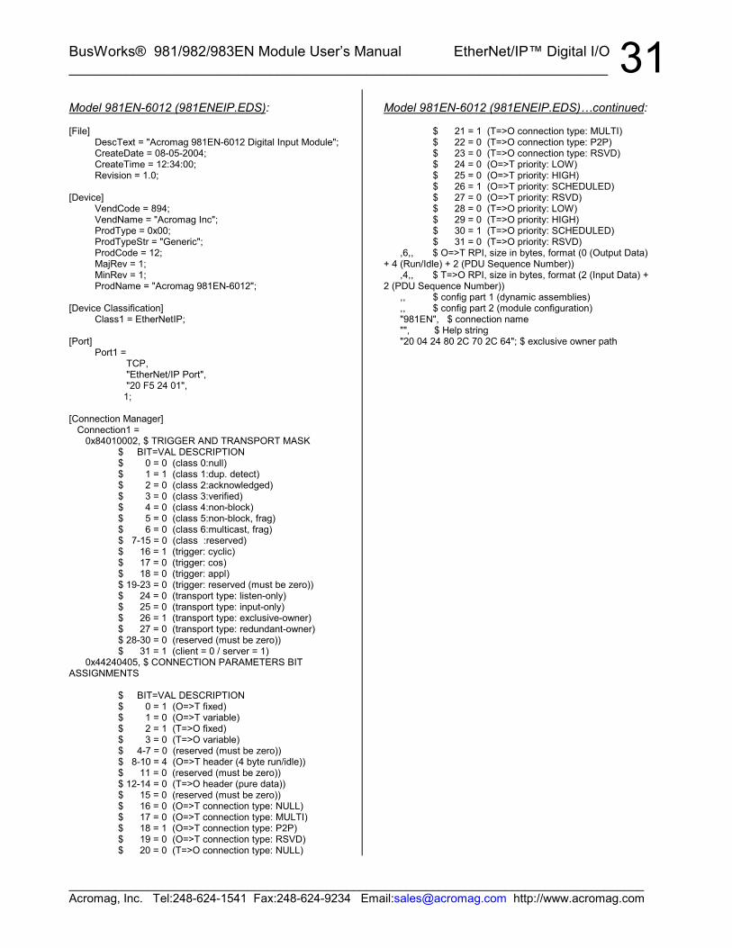
BusWorks® 981/982/983EN Module User’s Manual EtherNet/IP™ Digital I/O___________________________________________________________________
_______________________________________________________________________________________Acromag, Inc. Tel:248-624-1541 Fax:248-624-9234 Email:[email protected] http://www.acromag.com
31Model 981EN-6012 (981ENEIP.EDS):
[File]DescText = "Acromag 981EN-6012 Digital Input Module";CreateDate = 08-05-2004;CreateTime = 12:34:00;Revision = 1.0;
[Device]VendCode = 894;VendName = "Acromag Inc";ProdType = 0x00;ProdTypeStr = "Generic";ProdCode = 12;MajRev = 1;MinRev = 1;ProdName = "Acromag 981EN-6012";
[Device Classification]Class1 = EtherNetIP;
[Port]Port1 =
TCP, "EtherNet/IP Port", "20 F5 24 01", 1;
[Connection Manager] Connection1 = 0x84010002, $ TRIGGER AND TRANSPORT MASK $ BIT=VAL DESCRIPTION $ 0 = 0 (class 0:null) $ 1 = 1 (class 1:dup. detect) $ 2 = 0 (class 2:acknowledged) $ 3 = 0 (class 3:verified) $ 4 = 0 (class 4:non-block) $ 5 = 0 (class 5:non-block, frag) $ 6 = 0 (class 6:multicast, frag) $ 7-15 = 0 (class :reserved) $ 16 = 1 (trigger: cyclic) $ 17 = 0 (trigger: cos) $ 18 = 0 (trigger: appl) $ 19-23 = 0 (trigger: reserved (must be zero)) $ 24 = 0 (transport type: listen-only) $ 25 = 0 (transport type: input-only) $ 26 = 1 (transport type: exclusive-owner) $ 27 = 0 (transport type: redundant-owner) $ 28-30 = 0 (reserved (must be zero)) $ 31 = 1 (client = 0 / server = 1) 0x44240405, $ CONNECTION PARAMETERS BITASSIGNMENTS
$ BIT=VAL DESCRIPTION $ 0 = 1 (O=>T fixed) $ 1 = 0 (O=>T variable) $ 2 = 1 (T=>O fixed) $ 3 = 0 (T=>O variable) $ 4-7 = 0 (reserved (must be zero)) $ 8-10 = 4 (O=>T header (4 byte run/idle)) $ 11 = 0 (reserved (must be zero)) $ 12-14 = 0 (T=>O header (pure data)) $ 15 = 0 (reserved (must be zero)) $ 16 = 0 (O=>T connection type: NULL) $ 17 = 0 (O=>T connection type: MULTI) $ 18 = 1 (O=>T connection type: P2P) $ 19 = 0 (O=>T connection type: RSVD) $ 20 = 0 (T=>O connection type: NULL)
Model 981EN-6012 (981ENEIP.EDS)…continued:
$ 21 = 1 (T=>O connection type: MULTI) $ 22 = 0 (T=>O connection type: P2P) $ 23 = 0 (T=>O connection type: RSVD) $ 24 = 0 (O=>T priority: LOW) $ 25 = 0 (O=>T priority: HIGH) $ 26 = 1 (O=>T priority: SCHEDULED) $ 27 = 0 (O=>T priority: RSVD) $ 28 = 0 (T=>O priority: LOW) $ 29 = 0 (T=>O priority: HIGH) $ 30 = 1 (T=>O priority: SCHEDULED) $ 31 = 0 (T=>O priority: RSVD) ,6,, $ O=>T RPI, size in bytes, format (0 (Output Data)+ 4 (Run/Idle) + 2 (PDU Sequence Number)) ,4,, $ T=>O RPI, size in bytes, format (2 (Input Data) +2 (PDU Sequence Number)) ,, $ config part 1 (dynamic assemblies) ,, $ config part 2 (module configuration) "981EN", $ connection name "", $ Help string "20 04 24 80 2C 70 2C 64"; $ exclusive owner path
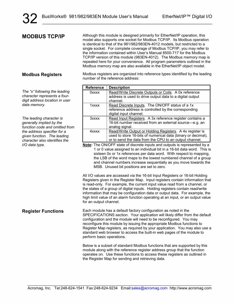
BusWorks® 981/982/983EN Module User’s Manual EtherNet/IP™ Digital I/O__________________________________________________________________
_______________________________________________________________________________________Acromag, Inc. Tel:248-624-1541 Fax:248-624-9234 Email:[email protected] http://www.acromag.com
32Although this module is designed primarily for EtherNet/IP operation, thismodel also supports one socket for Modbus TCP/IP. Its Modbus operationis identical to that of the 981/982/983EN-4012 models, but restricted to asingle socket. For complete coverage of Modbus TCP/IP, you may refer tothe information contained within User’s Manual 8500-717 for the ModbusTCP/IP version of this module (983EN-4012). The Modbus memory map isrepeated here for your convenience. All program parameters outlined in theModbus memory map are also available in the EtherNet/IP object model.
Modbus registers are organized into reference types identified by the leadingnumber of the reference address:
Reference Description0xxxx Read/Write Discrete Outputs or Coils. A 0x reference
address is used to drive output data to a digital outputchannel.
1xxxx Read Discrete Inputs. The ON/OFF status of a 1xreference address is controlled by the correspondingdigital input channel.
3xxxx Read Input Registers. A 3x reference register contains a16-bit number received from an external source—e.g. ananalog signal.
4xxxx Read/Write Output or Holding Registers. A 4x register isused to store 16-bits of numerical data (binary or decimal),or to send the data from the CPU to an output channel.
Note: The ON/OFF state of discrete inputs and outputs is represented by a1 or 0 value assigned to an individual bit in a 16-bit data word. This issixteen 0x or 1x references per data word. With respect to mapping,the LSB of the word maps to the lowest numbered channel of a groupand channel numbers increase sequentially as you move towards theMSB. Unused bit positions are set to zero.
All I/O values are accessed via the 16-bit Input Registers or 16-bit HoldingRegisters given in the Register Map. Input registers contain information thatis read-only. For example, the current input value read from a channel, orthe states of a group of digital inputs. Holding registers contain read/writeinformation that may be configuration data or output data. For example, thehigh limit value of an alarm function operating at an input, or an output valuefor an output channel.
Each module has a default factory configuration as noted in theSPECIFICATIONS section. Your application will likely differ from the defaultconfiguration and the module will need to be reconfigured. You mayreconfigure this module by issuing the appropriate Modbus functions toRegister Map registers, as required by your application. You may also use astandard web browser to access the built-in web pages of the module toperform basic operations.
Below is a subset of standard Modbus functions that are supported by thismodule along with the reference register address group that the functionoperates on. Use these functions to access these registers as outlined inthe Register Map for sending and retrieving data.
MODBUS TCP/IP
Modbus Registers
The “x” following the leadingcharacter represents a four-digit address location in userdata memory.
The leading character isgenerally implied by thefunction code and omitted fromthe address specifier for agiven function. The leadingcharacter also identifies theI/O data type.
Register Functions
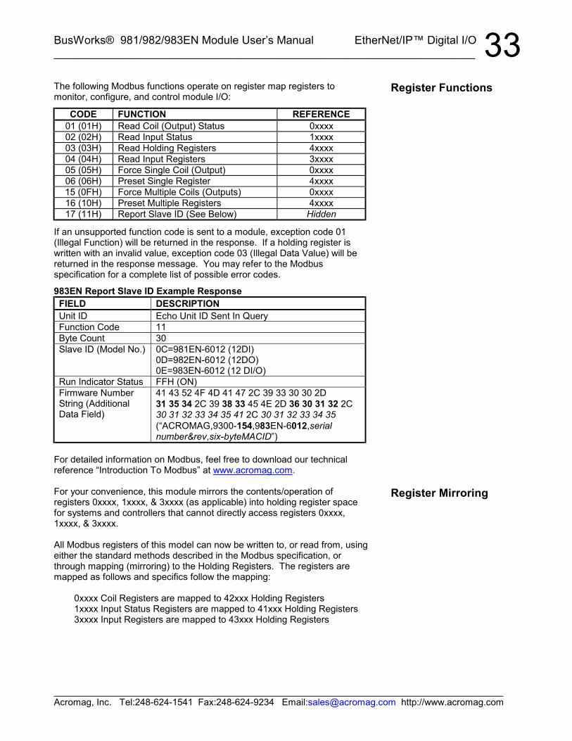
BusWorks® 981/982/983EN Module User’s Manual EtherNet/IP™ Digital I/O___________________________________________________________________
_______________________________________________________________________________________Acromag, Inc. Tel:248-624-1541 Fax:248-624-9234 Email:[email protected] http://www.acromag.com
33The following Modbus functions operate on register map registers tomonitor, configure, and control module I/O:
CODE FUNCTION REFERENCE01 (01H) Read Coil (Output) Status 0xxxx02 (02H) Read Input Status 1xxxx03 (03H) Read Holding Registers 4xxxx04 (04H) Read Input Registers 3xxxx05 (05H) Force Single Coil (Output) 0xxxx06 (06H) Preset Single Register 4xxxx15 (0FH) Force Multiple Coils (Outputs) 0xxxx16 (10H) Preset Multiple Registers 4xxxx17 (11H) Report Slave ID (See Below) Hidden
If an unsupported function code is sent to a module, exception code 01(Illegal Function) will be returned in the response. If a holding register iswritten with an invalid value, exception code 03 (Illegal Data Value) will bereturned in the response message. You may refer to the Modbusspecification for a complete list of possible error codes.
983EN Report Slave ID Example ResponseFIELD DESCRIPTIONUnit ID Echo Unit ID Sent In QueryFunction Code 11Byte Count 30Slave ID (Model No.) 0C=981EN-6012 (12DI)
0D=982EN-6012 (12DO)0E=983EN-6012 (12 DI/O)
Run Indicator Status FFH (ON)Firmware NumberString (AdditionalData Field)
41 43 52 4F 4D 41 47 2C 39 33 30 30 2D31 35 34 2C 39 38 33 45 4E 2D 36 30 31 32 2C30 31 32 33 34 35 41 2C 30 31 32 33 34 35(“ACROMAG,9300-154,983EN-6012,serialnumber&rev,six-byteMACID”)
For detailed information on Modbus, feel free to download our technicalreference “Introduction To Modbus” at www.acromag.com.
For your convenience, this module mirrors the contents/operation ofregisters 0xxxx, 1xxxx, & 3xxxx (as applicable) into holding register spacefor systems and controllers that cannot directly access registers 0xxxx,1xxxx, & 3xxxx.
All Modbus registers of this model can now be written to, or read from, usingeither the standard methods described in the Modbus specification, orthrough mapping (mirroring) to the Holding Registers. The registers aremapped as follows and specifics follow the mapping:
0xxxx Coil Registers are mapped to 42xxx Holding Registers1xxxx Input Status Registers are mapped to 41xxx Holding Registers3xxxx Input Registers are mapped to 43xxx Holding Registers
Register Functions
Register Mirroring
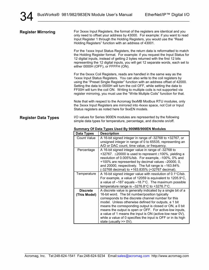
BusWorks® 981/982/983EN Module User’s Manual EtherNet/IP™ Digital I/O__________________________________________________________________
_______________________________________________________________________________________Acromag, Inc. Tel:248-624-1541 Fax:248-624-9234 Email:[email protected] http://www.acromag.com
34For 3xxxx Input Registers, the format of the registers are identical and youonly need to offset your address by 43000. For example: if you want to readInput Register 1 through the Holding Registers, you would use the “ReadHolding Registers” function with an address of 43001.
For the 1xxxx Input Status Registers, the return data is reformatted to matchthe Holding Register format. For example: if you request the Input Status for12 digital inputs, instead of getting 2 bytes returned with the first 12 bitsrepresenting the 12 digital inputs, you will get 12 separate words, each set toeither 0000H (OFF), or FFFFH (ON).
For the 0xxxx Coil Registers, reads are handled in the same way as the1xxxx Input Status Registers. You can also write to the coil registers byusing the “Preset Single Register” function with an address offset of 42000.Setting the data to 0000H will turn the coil OFF, while setting the data toFF00H will turn the coil ON. Writing to multiple coils is not supported viaregister mirroring, you must use the “Write Multple Coils” function for that.
Note that with respect to the Acromag 9xxMB Modbus RTU modules, onlythe 3xxxx Input Registers are mirrored into 4xxxx space, not Coil or InputStatus registers as noted here for 9xxEN models.
I/O values for Series 900EN modules are represented by the followingsimple data types for temperature, percentage, and discrete on/off.
Summary Of Data Types Used By 900MB/900EN ModulesData Types DescriptionCount Value A 16-bit signed integer in range of -32768 to +32767, or
unsigned integer in range of 0 to 65535, representing anA/D or DAC count, time value, or frequency.
Percentage A 16-bit signed integer value in range of -32768 to+32767. ±20000 is used to represent ±100%, yielding aresolution of 0.005%/lsb. For example, -100%, 0% and+100% are represented by decimal values –20000, 0,and 20000, respectively. The full range is –163.84%(-32768 decimal) to +163.835% (+32767 decimal).
Temperature A 16-bit signed integer value with resolution of 0.1°C/lsb.For example, a value of 12059 is equivalent to 1205.9°C,a value of –187 equals –18.7°C. The maximum possibletemperature range is –3276.8°C to +3276.7°C.
Discrete(This Model)
A discrete value is generally indicated by a single bit of a16-bit word. The bit number/position typicallycorresponds to the discrete channel number for thismodel. Unless otherwise defined for outputs, a 1 bitmeans the corresponding output is closed or ON, a 0 bitmeans the output is open or OFF. For active-low inputs,a value of 1 means the input is ON (active-low near 0V),while a value of 0 specifies the input is OFF or in its highstate (usually >> 0V).
Register Mirroring
Register Data Types
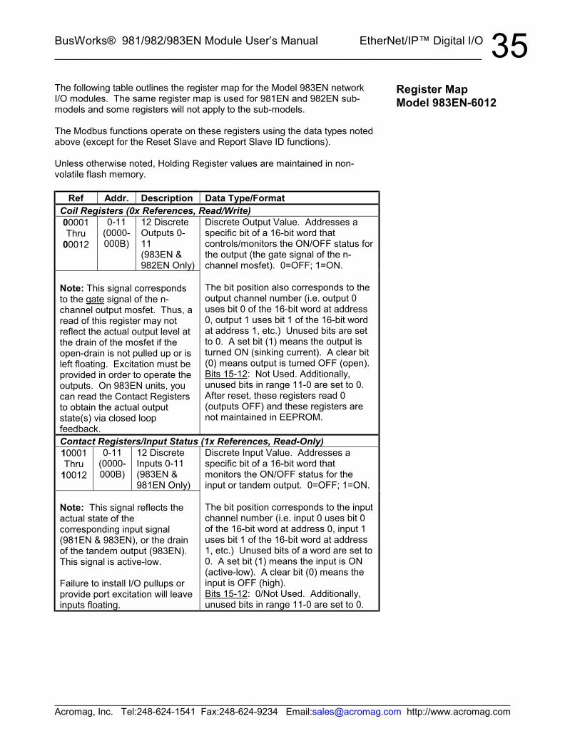
BusWorks® 981/982/983EN Module User’s Manual EtherNet/IP™ Digital I/O___________________________________________________________________
_______________________________________________________________________________________Acromag, Inc. Tel:248-624-1541 Fax:248-624-9234 Email:[email protected] http://www.acromag.com
35The following table outlines the register map for the Model 983EN networkI/O modules. The same register map is used for 981EN and 982EN sub-models and some registers will not apply to the sub-models.
The Modbus functions operate on these registers using the data types notedabove (except for the Reset Slave and Report Slave ID functions).
Unless otherwise noted, Holding Register values are maintained in non-volatile flash memory.
Ref Addr. Description Data Type/FormatCoil Registers (0x References, Read/Write)00001Thru
00012
0-11(0000-000B)
12 DiscreteOutputs 0-11(983EN &982EN Only)
Discrete Output Value. Addresses aspecific bit of a 16-bit word thatcontrols/monitors the ON/OFF status forthe output (the gate signal of the n-channel mosfet). 0=OFF; 1=ON.
Note: This signal correspondsto the gate signal of the n-channel output mosfet. Thus, aread of this register may notreflect the actual output level atthe drain of the mosfet if theopen-drain is not pulled up or isleft floating. Excitation must beprovided in order to operate theoutputs. On 983EN units, youcan read the Contact Registersto obtain the actual outputstate(s) via closed loopfeedback.
The bit position also corresponds to theoutput channel number (i.e. output 0uses bit 0 of the 16-bit word at address0, output 1 uses bit 1 of the 16-bit wordat address 1, etc.) Unused bits are setto 0. A set bit (1) means the output isturned ON (sinking current). A clear bit(0) means output is turned OFF (open).Bits 15-12: Not Used. Additionally,unused bits in range 11-0 are set to 0.After reset, these registers read 0(outputs OFF) and these registers arenot maintained in EEPROM.
Contact Registers/Input Status (1x References, Read-Only)10001Thru
10012
0-11(0000-000B)
12 DiscreteInputs 0-11(983EN &981EN Only)
Discrete Input Value. Addresses aspecific bit of a 16-bit word thatmonitors the ON/OFF status for theinput or tandem output. 0=OFF; 1=ON.
Note: This signal reflects theactual state of thecorresponding input signal(981EN & 983EN), or the drainof the tandem output (983EN).This signal is active-low.
Failure to install I/O pullups orprovide port excitation will leaveinputs floating.
The bit position corresponds to the inputchannel number (i.e. input 0 uses bit 0of the 16-bit word at address 0, input 1uses bit 1 of the 16-bit word at address1, etc.) Unused bits of a word are set to0. A set bit (1) means the input is ON(active-low). A clear bit (0) means theinput is OFF (high).Bits 15-12: 0/Not Used. Additionally,unused bits in range 11-0 are set to 0.
Register MapModel 983EN-6012
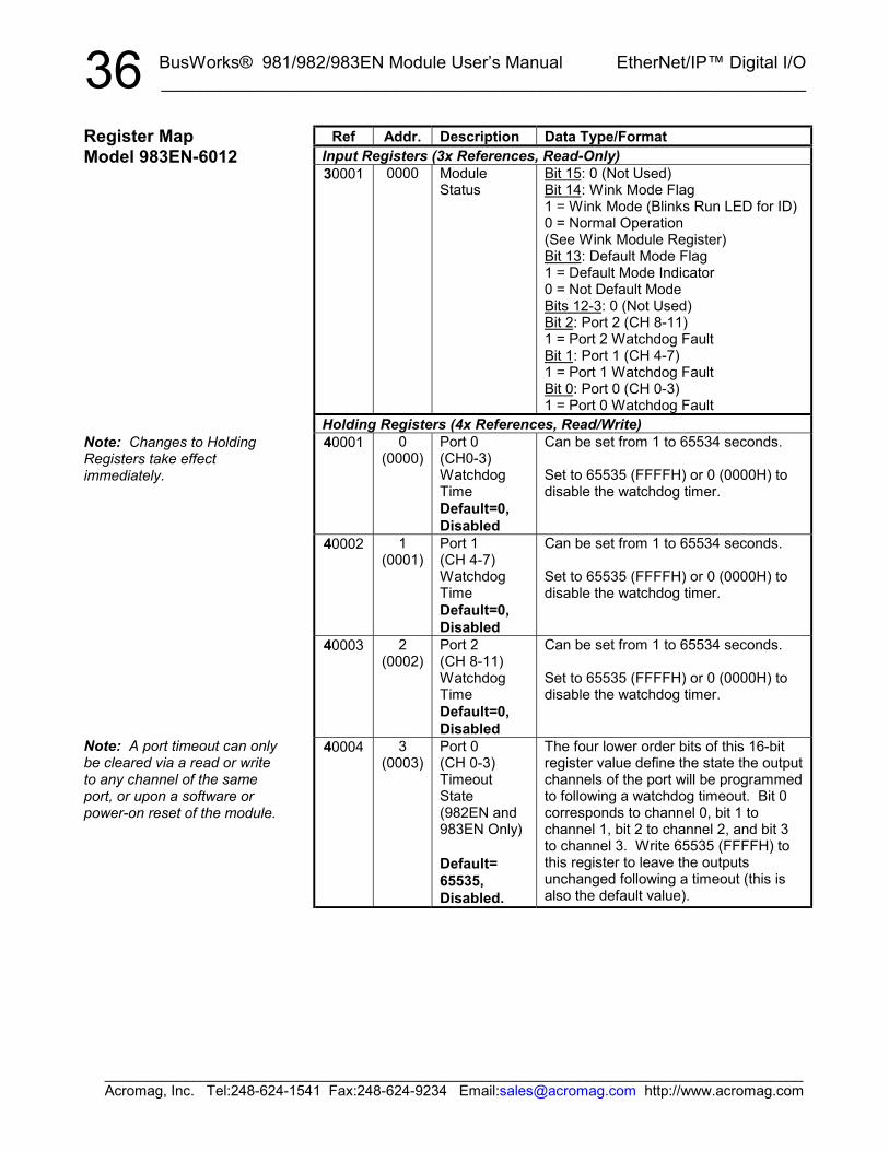
BusWorks® 981/982/983EN Module User’s Manual EtherNet/IP™ Digital I/O__________________________________________________________________
_______________________________________________________________________________________Acromag, Inc. Tel:248-624-1541 Fax:248-624-9234 Email:[email protected] http://www.acromag.com
36Ref Addr. Description Data Type/Format
Input Registers (3x References, Read-Only)30001 0000 Module
StatusBit 15: 0 (Not Used)Bit 14: Wink Mode Flag1 = Wink Mode (Blinks Run LED for ID)0 = Normal Operation(See Wink Module Register)Bit 13: Default Mode Flag1 = Default Mode Indicator0 = Not Default ModeBits 12-3: 0 (Not Used)Bit 2: Port 2 (CH 8-11)1 = Port 2 Watchdog FaultBit 1: Port 1 (CH 4-7)1 = Port 1 Watchdog FaultBit 0: Port 0 (CH 0-3)1 = Port 0 Watchdog Fault
Holding Registers (4x References, Read/Write)40001 0
(0000)Port 0(CH0-3)WatchdogTimeDefault=0,Disabled
Can be set from 1 to 65534 seconds.
Set to 65535 (FFFFH) or 0 (0000H) todisable the watchdog timer.
40002 1(0001)
Port 1(CH 4-7)WatchdogTimeDefault=0,Disabled
Can be set from 1 to 65534 seconds.
Set to 65535 (FFFFH) or 0 (0000H) todisable the watchdog timer.
40003 2(0002)
Port 2(CH 8-11)WatchdogTimeDefault=0,Disabled
Can be set from 1 to 65534 seconds.
Set to 65535 (FFFFH) or 0 (0000H) todisable the watchdog timer.
40004 3(0003)
Port 0(CH 0-3)TimeoutState(982EN and983EN Only)
Default=65535,Disabled.
The four lower order bits of this 16-bitregister value define the state the outputchannels of the port will be programmedto following a watchdog timeout. Bit 0corresponds to channel 0, bit 1 tochannel 1, bit 2 to channel 2, and bit 3to channel 3. Write 65535 (FFFFH) tothis register to leave the outputsunchanged following a timeout (this isalso the default value).
Register MapModel 983EN-6012
Note: Changes to HoldingRegisters take effectimmediately.
Note: A port timeout can onlybe cleared via a read or writeto any channel of the sameport, or upon a software orpower-on reset of the module.

BusWorks® 981/982/983EN Module User’s Manual EtherNet/IP™ Digital I/O___________________________________________________________________
_______________________________________________________________________________________Acromag, Inc. Tel:248-624-1541 Fax:248-624-9234 Email:[email protected] http://www.acromag.com
37Ref Addr. Description Data Type/Format
Holding Registers (4x References, Read/Write)40005 4
(0004)Port 1(CH 4-7)TimeoutState(982EN and983EN Only)
Default=65535,Disabled.
The four lower order bits of this 16-bitregister value define the state the outputchannels of the port will be programmedto following a watchdog timeout. Bit 0corresponds to channel 4, bit 1 tochannel 5, bit 2 to channel 6, and bit 3to channel 7. Write 65535 (FFFFH) tothis register to leave the outputsunchanged following a timeout (this isalso the default value).
40006 5(0005)
Port 2(CH 8-11)TimeoutState(982EN and983EN Only)
Default=65535,Disabled.
The four lower order bits of this 16-bitregister value define the state the outputchannels of the port will be programmedto following a watchdog timeout. Bit 0corresponds to channel 8, bit 1 tochannel 9, bit 2 to channel 10, and bit 3to channel 11. Write 65535 (FFFFH) tothis register to leave the outputsunchanged following a timeout (this isalso the default value).
40007 6(0006)
Wink ModuleToggleRegister
Write 21845 (5555H) to this register tocause the module to “wink” its greenRun LED in order to ID the module.Write the same value a second time tostop “winking”. This register will alwaysread back as 0000H. Use the ModuleStatus Register wink mode flag (bit 14)to determine the wink state.
41001...
This blockMirrors 1xxxxRegisters.
Refer to Register Mirroring. 1xxxxInput Status Registers are mapped tothe 41xxx Holding Register space usingan address offset of 41000.
42001...
This blockMirrors 0xxxxRegisters.
Refer to Register Mirroring. 0xxxxCoil Registers are mapped to the 42xxxHolding Register space using anaddress offset of 42000.
43001...
This blockMirrors 3xxxxRegisters.
Refer to Register Mirroring. 3xxxxInput Registers are mapped to the43xxx Holding Register space using anaddress offset of 43000.
Register MapModel 983EN-6012
Note: Clearing a timeout viaan I/O read or write does notreturn the output(s) to theirinitial state. They remain intheir timeout states untilotherwise written.
Configuration variables storedin holding registers (4xxxxreference addresses) aremaintained in EEPROM exceptas noted. Changes to theseregister parameters take effectimmediately.
A set bit (1) means the outputis turned ON (sinking current).A clear bit (0) means output isturned OFF (open).
BusWorks® 981/982/983EN Module User’s Manual EtherNet/IP™ Digital I/O__________________________________________________________________
_______________________________________________________________________________________Acromag, Inc. Tel:248-624-1541 Fax:248-624-9234 Email:[email protected] http://www.acromag.com
38These DIN-rail mount, industrial ethernet, digital I/O modules include twelvedigital inputs (981EN), twelve digital outputs (982EN), or twelve combinationdigital input/output channels (983EN), and provide an isolated 10/100BaseTEthernet port for monitoring and control. Units are DC-powered and includereverse polarity protection. Outputs are open-drain, low-side switches, whileinputs are active-low. Channel I/O, network, and power circuits are isolated.Outputs have high voltage/current capacity for discrete on/off control ofexternal devices. Non-inverting, buffered inputs provide support for digitallevel sensing, or for simply reading back the tandem output (983EN only).I/O channels share common. Pull-up resistors to the port EXC supply (everyfour channels) are installed in sockets on the board. Non-volatilereprogrammable memory in the module stores configuration information.
The BusWorks model prefix “900” denotes the Series 900 network I/Ofamily. The “EN” suffix denotes EtherNet. Select 981EN for digital inputs,982EN for digital outputs, or 983EN for tandem digital inputs and outputs.The four digit suffix of this model number represents the following options,respectively: “6” = EtherNet/IP; “0” = Default; “12” = 12 Channels.
Twelve active-low, buffered inputs, with a common connection (RTN). ForDC voltage applications only. Inputs include transient suppression and haveseries connected 100KΩ resistors, plus diode over-voltage clamps to theinternal +5V supply. Sockets are provided at each port (group of fourchannels) for installation of SIP resistor networks that serve as pullups to theport EXC supply terminal. 5.6K pull-up resistor SIP’s are installed from thefactory. External excitation (pull-up supply) is required for proper operationand is connected between the port EXC and RTN terminals.
Input Signal Voltage Range: 0 to +35VDC.Input Current: 293uA, typical at 35VDC. This is computed as the applied
input voltage minus 5.7V, divided by the series 100KΩ input resistance.Input Signal Threshold: TTL compatible with 100mV of hysteresis, typical.
Low-to-High threshold is 1.7VDC typical, High-to-Low threshold is1.6VDC, typical. Limit logic transition to TTL levels of 0.8VDC (MaxLOW level) and 2.0VDC (Min HIGH level).
Input Resistance: 100KΩ, typical.Input Hysteresis: 100mVDC typical.Input Response Time: 800ns typical, measured from input step to logic
transfer. Actual input response will vary with interrupts.
Twelve open-drain, DMOS mosfet switches with a common sourceconnection at the port RTN terminal. For DC voltage and current-sinkingapplications only. Outputs have built-in transient protection. Sockets areprovided at each port (four channels) for quick replacement and installationof SIP resistor networks that serve as pullups to the port EXC supplyterminal. 5.6K pull-up resistor SIP’s are installed from the factory.
Output “OFF” Voltage Range: 0 to 35V DC. Limit voltage to 35V or lessor damage to the unit may result.
Output “OFF” Leakage Current: : 0.1uA typical, 50uA maximum (mosfetonly, 25°C, 35V). Does not include the tandem input bias current of983EN models (see below).
SPECIFICATIONS
Model Numbers981EN-6012 (Input Only)982EN-6012 (Output Only)983EN-6012 (Input/Output)
Digital Inputs(981EN & 983EN Only)
Digital Outputs(982EN & 983EN Only)

BusWorks® 981/982/983EN Module User’s Manual EtherNet/IP™ Digital I/O___________________________________________________________________
_______________________________________________________________________________________Acromag, Inc. Tel:248-624-1541 Fax:248-624-9234 Email:[email protected] http://www.acromag.com
39Note (983EN): The 100KΩ series input buffer resistors in combinationwith the +5V voltage clamps at the input buffers will tend to increase theoff-state drain current with increased drain voltage (up to 0.3mA at35V). This is due to the fact that the input buffer circuitry and outputmosfet drain circuitry are connected in tandem to the same I/O pin forthe Model 983EN.
Output “ON” Current Range: 0 to 500mA DC, continuous (up to 6A totalfor all 12 channels combined). No deration required at elevatedambients. Group one RTN per each group of 4 outputs.
Output Rds ON Resistance: 0.13Ω typical, 0.28Ω Maximum.Output Response Time: 220us typical measured from output trigger at the
controller to corresponding input transition at the controller. Actualswitch time will vary with output load and interrupts.Note: Per UL, when the outputs are used to control interposing relaysfor switching AC and DC devices of higher voltage/current, the coilratings for the interposing relay shall not exceed 24VDC, 100mA.
I/O Pullups & Socket: I/O channels include sockets for installation of SIPresistor networks to act as pull-ups for the channel (see I/O PullupResistor Installation drawing of page 4). These resistors are located onthe plug-in I/O board (cover removal required). A SIP socket isincluded for each group of four channels (port) and a 5.6KΩ resistorSIP is installed from the factory. The even-numbered pins of thesesockets (common leads) connect to the port EXC+ terminal. Anexternal excitation supply is typically connected between the EXC+ andRTN terminals of the port. The recommended SIP resistor is a fourisolated resistor type (8 pins) and may be obtained from Acromag oranother vendor. These SIP resistors typically come rated for 0.2W,0.3W, 0.4W, or 0.5W per element. For example, refer to Bourns4308R-102, 4308M-102, or 4308H-102 parts. You may also refer toDale CSC08C03, MSP08C03, or MSM08C-03 parts. The 5.6KΩ SIPprovided is a high-power type from Bourns (part number 4308H-102-562) and is rated at 0.5W per resistor up to 70°C. See I/O PullupResistor Installation section for more information.IMPORTANT: When selecting a SIP resistor, be sure to limit theindividual resistor power dissipation to less than the rated power perelement. Further, do not exceed 500mA of drain current per output, or2A total per RTN terminal.
Excitation (External): External voltage is applied between the port EXCand RTN terminals and must be limited to 35V or less. The EXCterminal is tied to the even-numbered pins of the resistor SIP socketprovided for each port or group of 4 channels.
Dimensions: 1.05 inches wide, 4.68 inches tall, 4.35 inches deep. Refer tothe dimensions drawing at the front of this manual.
DIN Rail Mount: Type EN50022; “T” rail (35mm).I/O Connectors: Removable plug-in type terminal blocks rated for
15A/300V; AWG #12-24 stranded or solid copper wire.Network Connector: 8-pin RJ-45 connector socket with metal shield
(shield is isolated and bypassed to earth ground at the GND terminalwith an isolation TVS and capacitor). Connections are wired MDI, asopposed to MDI-X. You must use a CAT-5 crossover cable to connectthis module to a PC. Otherwise you may use an auto-crossing Ethernetswitch, such as the Acromag 900EN-S005 to make connections.
Digital Outputs(982EN & 983EN Only)
To control higher voltagesand/or currents, or forcontrolling AC, an interposingrelay may be used (see Note).
General Specifications
Enclosure and Physical

BusWorks® 981/982/983EN Module User’s Manual EtherNet/IP™ Digital I/O__________________________________________________________________
_______________________________________________________________________________________Acromag, Inc. Tel:248-624-1541 Fax:248-624-9234 Email:[email protected] http://www.acromag.com
40RJ-45 Signal (MDI) Description
1 Tx+ Transmit Positive2 Tx- Transmit Negative3 Rx+ Receive Positive4 Not Used Connects to Pin 55 Not Used Connects to Pin 46 Rx- Receive Negative7 Not Used Connects to Pin 88 Not Used Connects to Pin 7
Case Material: Self-extinguishing NYLON type 6.6 polyamide thermoplasticUL94 V-2, color beige; general purpose NEMA Type 1 enclosure.
Printed Circuit Boards: Military grade FR-4 epoxy glass.Shipping Weight: 1 pound (0.45 Kg) packed.
Safety Approvals: CE marked (EMC Directive 89/336/EEC), UL Listed(UL3121-First Edition, UL1604), cUL Listed (Canada Standard C22.2,No. 1010.1-92), Hazardous Locations: Class 1; Division 2; Groups A, B,C, and D.
Conformance: EtherNet/IP CONFORMANCE TESTED™.
Operating Temperature: -25°C to +70°C (-13°F to +158°F).Storage Temperature: -40°C to +85°C (-40°F to +185°F).Relative Humidity: 5 to 95%, non-condensing.Power Requirements: Non-polarized 15-36V DC SELV (Safety Extra Low
Voltage). Observe proper polarity. See table for current.
Supply 981/982/983EN-6012 Current Draw15V 112mA Typical, 123mA Maximum18V 96mA Typical, 106mA Maximum24V 73mA Typical, 80mA Maximum36V 54mA Typical, 59mA Maximum
CAUTION: Risk of Electric Shock – More than one disconnect switch maybe required to de-energize equipment before servicing.
Isolation: I/O channel, power, and network circuits are isolated from eachother for common-mode voltages up to 250VAC, or 354V DC off DCpower ground, on a continuous basis (will withstand 1500VAC dielectricstrength test for one minute without breakdown). Complies with testrequirements of ANSI/ISA-82.01-1988 for voltage rating specified.
Installation Category: Designed to operate in an installation in a PollutionDegree 2 environment with an installation category (over-voltagecategory) II rating.
Electromagnetic Interference Immunity (EMI): Inputs/outputs havedemonstrated resistance to inadvertent state changes with interferencefrom switching solenoids, commutator motors, and drill motors.
Enclosure & Physical
Agency Approvals
Environmental
CAUTION: Do not exceed36VDC peak, to avoid damageto the module.
External Fuse: Select a highsurge tolerant fuse rated for1A or less to protect unit.
Note that I/O channels are notisolated channel-to-channel.
BusWorks® 981/982/983EN Module User’s Manual EtherNet/IP™ Digital I/O___________________________________________________________________
_______________________________________________________________________________________Acromag, Inc. Tel:248-624-1541 Fax:248-624-9234 Email:[email protected] http://www.acromag.com
41Electromagnetic Compatibility (EMC) -Minimum Immunity Per European Norm EN50082-1:
Electrostatic Discharge (ESD) Immunity: 4KV direct contact and 8KVair-discharge to the enclosure port per EN61000-4-2.
Radiated Field Immunity (RFI): 10V/M, 80 to 1000MHz AM and900MHz keyed carrier, per EN61000-4-3 and ENV50204.
Electrical Fast Transient Immunity (EFT): 2KV to power, and 1KV tosignal I/O per EN61000-4-4.
Conducted RF Immunity (CRFI): 10V rms, 150KHz to 80MHz, perEN61000-4-6.
Surge Immunity: 0.5KV per EN61000-4-5.Emissions Per European Norm EN50081-1:
Radiated Frequency Emissions: 30 to 1000MHz per EN55022 Class AWARNING: This is a Class A product. In a domestic environment, this
product may cause radio interference in which the user may berequired to take adequate measures.
IMPORTANT: Power, input, and output (I/O) wiring must be in accordancewith Class I, Division 2 wiring methods of Article 501-4(b) of the NationalElectrical Code, NFPA 70 for installations in the US, or as specified insection 18-1J2 of the Canadian Electrical Code for installations withinCanada and in accordance with the authority having jurisdiction.
This equipment is suitable for use in Class I, Division 2, Groups A, B,C, and D, or non-hazardous locations only.
WARNING – EXPLOSION HAZARD – Substitution of components mayimpair suitability for Class I, Division 2.
WARNING – EXPLOSION HAZARD – Do not disconnect equipment unlesspower has been switched off or the area is known to be non-hazardous.
Connector: Shielded RJ-45 socket, 8-pin, 10BaseT/100BaseTX.Wiring: Wired MDI. Unit does NOT support auto-crossover.Protocol: EtherNet/IP w/Web Browser Configuration. Unit also provides 1
socket connection for Modbus TCP/IP.IP Address: Default mode static IP address is 128.1.1.100.Port: Up to 10 sockets supported, uses port 502 (reserved for Modbus).Transient Protection: Transient Voltage Suppressors are applied
differentially at both the transmit and receive channels. The metalshield is capacitively coupled to earth ground terminal via an isolationTVS and capacitor.
Data Rate: Auto-sensed, 10Mbps or 100Mbps.Duplex: Auto-negotiated, Full or Half Duplex.Compliance: IEEE 802.3, 802.3u, 802.3x.EtherNet/IP Protocol Support: Uses built-in web pages for configuration
and control over ethernet via a standard web browser. Up to 10connections via EtherNet/IP, and 1 connection via Modbus TCP/IP (themodule uses the standard Modbus TCP/IP socket 502).
Rx/Tx Memory: 8K bytes internal SRAM memory for receive and transmitbuffers (FIFO).
EnvironmentalThese limits represent theminimum requirements of thestandard, but product hastypically been tested to complywith higher standards in somecases.
Ethernet Interface

BusWorks® 981/982/983EN Module User’s Manual EtherNet/IP™ Digital I/O__________________________________________________________________
_______________________________________________________________________________________Acromag, Inc. Tel:248-624-1541 Fax:248-624-9234 Email:[email protected] http://www.acromag.com
42Communication Distance: The distance between two devices on an
Ethernet network is generally limited to 100 meters using recommendedcopper cable. Distances may be extended using hubs, switches, orfiber optic transmission. However, the total round trip delay time mustnot exceed 512 bit times for collision detection to work properly.
Port Status Indicators: Green LED indicates link status (ON if auto-negotiation has successfully established a connection), yellow LEDindicates activity (ethernet connection is busy/traffic is present).
Address: The module IP address can be preset by the user (static) andloaded from internal non-volatile memory, or it can be automaticallyacquired at startup via a network server using a BOOTP (BootstrapProtocol), or DHCP (Dynamic Host Configuration Protocol). The unitalso includes a default mode toggle switch to cause the module toassume a “known” fixed static IP address of 128.1.1.100 fortroubleshooting purposes. The module may also use DHCP with afallback to the static IP address, or the last DHCP assigned address.
LED Indicators:RUN (Green) - Constant ON if power is on and unit is OK. Continuous
flashing ON/OFF indicates unit is in “wink” ID mode.ST (Yellow) – Slowly blinks ON/OFF in default mode, blinks rapidly if a
watchdog timeout has occurred.LINK (Green) – Indicates Ethernet link status (ON if auto-negotiation has
successfully established a connection).ACT (Yellow) – Indicates Ethernet activity (Ethernet connection is
busy/traffic is present).Output (Yellow, One Per Output) – ON if output relay is ON (closed) or
input is asserted low. Note: This LED is driven by the input buffer of981/983EN units and will reflect the actual input state. On 982ENunits (output only), this LED is driven by the output mosfet gate signaland may not reflect the actual open-drain output state (for example, ifthe outputs are floating or not pulled up).
Controls:Reset/Default Address Switch: This momentary toggle switch is
located on the front panel and is used to either reset the module(toggle right), or toggle the module into, or out of DefaultCommunication Mode (toggle left). In Default Mode, the moduleassumes the fixed static IP address “128.1.1.100”, a default subnetmask “255.255.255.0”, a default username of “User”, and a defaultpassword of “password00”. This switch can also be used to restorethe module to its initial factory configuration by holding this switch inits default position while powering up the unit (see “Getting Out OfTrouble” in the Troubleshooting section for more information).
Ethernet Interface
Refer to Acromag ApplicationNote 8500-734 for instructionson how to change the IPaddress of your PC networkinterface card in order to talkto an Acromag module.
Controls & Indicators

BusWorks® 981/982/983EN Module User’s Manual EtherNet/IP™ Digital I/O___________________________________________________________________
_______________________________________________________________________________________Acromag, Inc. Tel:248-624-1541 Fax:248-624-9234 Email:[email protected] http://www.acromag.com
43The minimum cable required for full operation of this device is Category 5.The term “Category” refers to classifications of UTP (Unshielded TwistedPair) cables. There are 3 main categories of cable – Category 3, Category4, and Category 5. The differences in classification is found in their electricalperformance and this is documented in the TIA/EIA 568A standard.Category 5 cable includes four twisted wire pairs at eight twists per foot.
This device is designed for use in harsh industrial environments. Acromagrecommends the use of shielded cable when wiring to this device. SelectSTP (Shielded Twisted Pair) cable rather than UTP (Unshielded TwistedPair). The use of shielded cable will help protect the data being transmittedfrom harmful EMI (Electromagnetic Interference) and RFI (Radio FrequencyInterference). It will also help to lower your radiated emissions by keepingthe cable from emitting EMI and RFI.
There are two types of cable: solid cable and stranded cable. Strandedcables are more flexible than solid cables. But since attenuation is higher forstranded cables than solid conductor cables, these are generally reservedfor short runs and patch applications less than 6 meters.
Currently there are two types of shielding employed in Category 5 STPcable: single-shielded cable and double-shielded cable. Both of thesecables have the same core and jacket as UTP cables, but also include a thinfoil outer shield that covers all four twisted-wire pairs. Some variations willalso include a drain wire that encircles the outer foil. The double-shieldedversion adds an outer wire screen that wraps around the foil shield and alsofunctions as a drain wire. The drain wire or wire screen typically makescontact at each end of the cable with the metal shield around special RJ45plug connectors. The metal shield of these connectors then makes contactwith the metal shield of shielded RJ45 sockets. The socket shield maymake direct contact with earth ground, or it may be capacitively coupled toearth ground. In the Acromag 9xxEN modules, this shield contacts earthground via a high voltage capacitor and transient voltage suppressor. Inaddition to minimizing radio frequency and electromagnetic interference, thisarrangement also has the added benefit of enhanced protection from ESD(Electro-Static Discharge).
Further, Acromag recommends the use of enhanced Category 5 cable(CAT-5e). This cable has all the characteristics of Category 5, but includesenhancements that help to minimize crosstalk. It is rated for frequencies upto 200MHz, double the rate of Category 5. Category 5e cable also has agreater number of turns-per-inch in its twisted pairs, making its performancemore suitable for applications that make use of all four wire pairs forsimultaneous bidirectional data transmission (full-duplex). This cable isdefined in TIA/EIA-568A-5 (Addendum 5).
ACCESSORYCABLES
BusWorks® 981/982/983EN Module User’s Manual EtherNet/IP™ Digital I/O__________________________________________________________________
_______________________________________________________________________________________Acromag, Inc. Tel:248-624-1541 Fax:248-624-9234 Email:[email protected] http://www.acromag.com
44Acromag offers the following cable accessories for use with this module:
Cable Model 5035-355 – A yellow, 3 foot long, single-shielded Category 5eSTP patch cable with drain wire and an RJ45 plug at both ends. Use thiscable to connect an Acromag 9xxEN I/O module to the Acromag 900EN-S005 switch.Cable Model 5035-360 – A green, 5 foot long, single-shielded Category 5eSTP crossover cable with a drain wire and an RJ45 plug at both ends. Thiscable performs the Ethernet crossover function and is used to connect a PCdirectly to an Acromag Series 9xxEN I/O module.
Note that you do not need to use a crossover cable to connect your PC tothis module if the Acromag 900EN-S005 switch is used between the PC andmodule, as the switch is auto-crossing. However, you must use a crossovercable when directly connecting your PC to a Series 9xxEN I/O Modulewithout the use of an auto-crossing switch or hub.
You may obtain cable in other lengths and colors as required for yourapplication from other vendors. For example, shielded CAT-5e cable isavailable from the following vendors:
• L-com Connectivity Products, www.L-com.com• Pro-Link, www.prolink-cables.com
For very noisy environments or in the presence of strong electrical fields, youcan obtain double-shielded CAT-5e cable and shielded RJ45 plugs from thefollowing vendors:
• L-com Connectivity Products, www.L-com.com, see cable modelTFSC2004 and shielded plug T8P8CSR.
• Regal Electronics, www.regalusa.com, see shielded plug model1003B-8P8CSR-C5.
Complete premium double-shielded Category 5e standard and crossovercables in variable lengths can be obtained from Lumberg atwww.lumbergusa.com (refer to their etherMate line). For example, specifyRJ45S-RJ45S-656/B/3M for a double-shielded, 3 meter straight cable.Specify RJ45S-RJ45S-656/BX/3M for a double-shielded, 3 meter crossovercable.
ACCESSORYCABLESPatch Cable &Crossover Cable