Embed Size (px)
Citation preview
H2020 5G-Coral Project
Grant No. 761586
D1.1 – 5G-CORAL initial system design, use cases, and requirements
Abstract
This is the first deliverable from WP1. It targets an initial scoping of the 5G-CORAL system
framework including the characterization of Edge and Fog resources, and the definition of
scenarios and use cases, system requirements and KPIs, and baseline architecture.
D1.1 – 5G-CORAL initial system design, use cases, and requirements 2
H2020-761586
Document properties
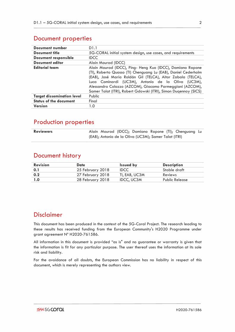
Document number D1.1
Document title 5G-CORAL initial system design, use cases, and requirements
Document responsible IDCC
Document editor Alain Mourad (IDCC)
Editorial team Alain Mourad (IDCC), Ping- Heng Kuo (IDCC), Damiano Rapone (TI), Roberto Quasso (TI) Chenguang Lu (EAB), Daniel Cederholm (EAB), José María Roldán Gil (TELCA), Aitor Zabala (TELCA), Luca Cominardi (UC3M), Antonio de la Oliva (UC3M), Alessandro Colazzo (AZCOM), Giacomo Parmeggiani (AZCOM), Samer Talat (ITRI), Robert Gdowski (ITRI), Simon Duqennoy (SICS)
Target dissemination level Public
Status of the document Final
Version 1.0
Production properties
Reviewers Alain Mourad (IDCC); Damiano Rapone (TI); Chenguang Lu
(EAB); Antonio de la Oliva (UC3M); Samer Talat (ITRI)
Document history
Revision Date Issued by Description
0.1 25 February 2018 IDCC Stable draft
0.2 27 February 2018 TI, EAB, UC3M Reviews
1.0 28 February 2018 IDCC, UC3M Public Release
Disclaimer
This document has been produced in the context of the 5G-Coral Project. The research leading to
these results has received funding from the European Community's H2020 Programme under
grant agreement Nº H2020-761586.
All information in this document is provided “as is" and no guarantee or warranty is given that
the information is fit for any particular purpose. The user thereof uses the information at its sole
risk and liability.
For the avoidance of all doubts, the European Commission has no liability in respect of this
document, which is merely representing the authors view.
D1.1 – 5G-CORAL initial system design, use cases, and requirements 3
H2020-761586
Table of Contents List of Figures .................................................................................................................................................... 4
List of Tables ..................................................................................................................................................... 4
List of Acronyms ................................................................................................................................................ 5
Executive Summary .......................................................................................................................................... 6
1 Introduction ............................................................................................................................................... 7
2 Characterization of Fog, Edge and Cloud ......................................................................................... 9
2.1 Characterization of Cloud.......................................................................................................... 10
2.1.1 Background .......................................................................................................................... 10
2.1.2 Characterization ................................................................................................................. 10
2.1.3 Cloud Infrastructure ............................................................................................................ 11
2.2 Characterization of Edge ........................................................................................................... 11
2.2.1 Background .......................................................................................................................... 11
2.2.2 Characterization ................................................................................................................. 11
2.2.3 Edge Infrastructure ............................................................................................................. 12
2.3 Characterization of Fog ............................................................................................................. 13
2.3.1 Background .......................................................................................................................... 13
2.3.2 Fog resource characteristics .............................................................................................. 13
2.3.3 Fog Infrastructure ................................................................................................................ 14
3 Scenarios and Use Cases ..................................................................................................................... 16
3.1 Low-Mobility Scenario – Shopping Mall ................................................................................. 16
3.1.1 Augmented Reality use case ............................................................................................ 17
3.1.2 Cloud Robotics use case .................................................................................................... 19
3.1.3 IoT Multi-RAT use case ....................................................................................................... 22
3.2 Medium-Mobility Scenario – Connected Cars ....................................................................... 23
3.2.1 Safety use case ................................................................................................................... 25
3.2.2 “Infotainment during a traffic-jam” use case ................................................................ 25
3.3 High-Mobility Scenario – High-Speed Train .......................................................................... 26
3.3.1 High-Speed Train use case ............................................................................................... 27
4 System Requirements, Innovations, and KPIs .................................................................................... 29
4.1 System Requirements ................................................................................................................... 29
4.1.1 Functional Technical Requirements ................................................................................... 29
4.1.2 Non-Functional Technical Requirements .......................................................................... 30
4.2 Key Performance Indicators, Metrics, and Innovations ......................................................... 31
4.3 Mapping of KPIs, Metrics and Innovations to Use Cases ..................................................... 33
4.3.1 Augmented Reality ............................................................................................................. 33
4.3.2 Cloud Robotics ..................................................................................................................... 34
4.3.3 IoT Multi-RAT ........................................................................................................................ 34
4.3.4 Connected Cars ................................................................................................................... 35
4.3.5 High-Speed Train ............................................................................................................... 36
5 Baseline Architecture and Mapping to Use Cases ......................................................................... 37
5.1 Functional Architecture of 5G-CORAL ..................................................................................... 37
5.2 Use Case Mapping to 5G-CORAL Baseline Architecture .................................................... 39
5.2.1 AR Navigation use case ..................................................................................................... 39
5.2.2 Cloud Robotics use case .................................................................................................... 39
5.2.3 IoT Multi-RAT use case ....................................................................................................... 40
5.2.4 Connected Cars use case .................................................................................................. 41
5.2.5 High-Speed Train use case ............................................................................................... 42
6 Conclusions .............................................................................................................................................. 43
D1.1 – 5G-CORAL initial system design, use cases, and requirements 4
H2020-761586
7 References .............................................................................................................................................. 44
List of Figures Figure 2-1: Cloud, Edge and Fog resources and characteristics ............................................................ 9
Figure 2-2: Two layer Clos fabric architecture ........................................................................................ 12
Figure 2-3: Architecture for a small Edge DC .......................................................................................... 12
Figure 3-1: Shopping Mall Scenario Decomposition ............................................................................... 16
Figure 3-2: AR navigation scenario ............................................................................................................ 18
Figure 3-3: Cloud Robotics in the Shopping Mall .................................................................................... 21
Figure 3-4: IoT Multi-RAT use case ............................................................................................................. 23
Figure 3-5: Connected Car Scenario ......................................................................................................... 24
Figure 3-6: High-Speed Train Scenario .................................................................................................... 28
Figure 5-1: 5G-CORAL Baseline Functional Architecture ....................................................................... 37
Figure 5-2: Mapping of AR Navigation Use Case to the 5G-CORAL architecture .......................... 39
Figure 5-3: Mapping of Cloud Robotics Use Case to the 5G-CORAL architecture ......................... 40
Figure 5-4: Mapping of IoT Multi-RAT Use Case to the 5G-CORAL architecture ............................ 41
Figure 5-5: Mapping of Connected Car Use Cases to the 5G-CORAL architecture ....................... 41
Figure 5-6: Mapping of High-speed train Use Case to the 5G-CORAL architecture ...................... 42
List of Tables Table 2-1: Cloud Infrastructure Equipment ............................................................................................... 11
Table 2-2: Edge Infrastructure Equipment ................................................................................................ 12
Table 2-3: Fog Products ............................................................................................................................... 14
Table 3-1: Computing resources type and location in the Shopping Mall scenario ......................... 16
Table 3-2: Stakeholders identification for the Shopping Mall scenario ............................................. 17
Table 3-3: Computing resources type and location in the Connected Cars scenario ...................... 24
Table 3-4: Stakeholders identification for the Connected Cars scenario ........................................... 25
Table 3-5: 4G LTE Ping results in the world ............................................................................................. 25
Table 3-6: Computing resources type and location in the high-Speed Train scenario .................... 26
Table 3-7: Stakeholders identification for the High-Speed Train scenario ....................................... 26
Table 4-1: Functional Technical Requirements .......................................................................................... 29
Table 4-2: Non-Functional Technical Requirements ................................................................................. 30
Table 4-3: 5G-PPP KPIs................................................................................................................................ 31
Table 4-4: 5G-CORAL System Performance Metrics ............................................................................. 32
Table 4-5: 5G-CORAL Key Innovations .................................................................................................... 32
Table 4-6: Mapping of KPIs to the AR Navigation Use Case ............................................................... 33
Table 4-7: KPIs and Innovations Mapping for AR Navigation Use Case ........................................... 33
Table 4-8: Mapping of KPIs to the Cloud Robotics Use Case .............................................................. 34
Table 4-9: KPIs and innovations coverage for Cloud robotics use case ............................................. 34
Table 4-10: Mapping of KPIs to the IoT Multi-RAT Use Case ............................................................. 34
Table 4-11: KPIs and Innovations Mapping for IoT Multi-RAT Use Case ........................................... 35
Table 4-12: Mapping of KPIs to the Connected Cars Use Cases ........................................................ 35
Table 4-13: KPIs and Innovations Mapping for Connected Cars Use Cases ..................................... 36
Table 4-14: Mapping of KPIs to the High-Speed Train Use Case ...................................................... 36
Table 4-15: KPIs and Innovations Mapping for High-SPeed TRain Use Case................................... 36
D1.1 – 5G-CORAL initial system design, use cases, and requirements 5
H2020-761586
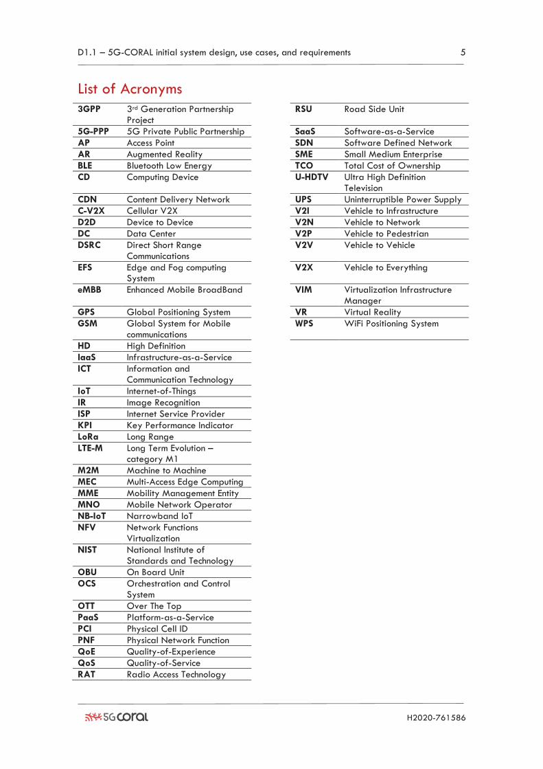
List of Acronyms
3GPP 3rd Generation Partnership Project
RSU Road Side Unit
5G-PPP 5G Private Public Partnership SaaS Software-as-a-Service
AP Access Point SDN Software Defined Network
AR Augmented Reality SME Small Medium Enterprise
BLE Bluetooth Low Energy TCO Total Cost of Ownership
CD Computing Device U-HDTV Ultra High Definition Television
CDN Content Delivery Network UPS Uninterruptible Power Supply
C-V2X Cellular V2X V2I Vehicle to Infrastructure
D2D Device to Device V2N Vehicle to Network
DC Data Center V2P Vehicle to Pedestrian
DSRC Direct Short Range Communications
V2V Vehicle to Vehicle
EFS Edge and Fog computing System
V2X Vehicle to Everything
eMBB Enhanced Mobile BroadBand VIM Virtualization Infrastructure Manager
GPS Global Positioning System VR Virtual Reality
GSM Global System for Mobile communications
WPS WiFi Positioning System
HD High Definition
IaaS Infrastructure-as-a-Service
ICT Information and Communication Technology
IoT Internet-of-Things
IR Image Recognition
ISP Internet Service Provider
KPI Key Performance Indicator
LoRa Long Range
LTE-M Long Term Evolution – category M1
M2M Machine to Machine
MEC Multi-Access Edge Computing
MME Mobility Management Entity
MNO Mobile Network Operator
NB-IoT Narrowband IoT
NFV Network Functions Virtualization
NIST National Institute of Standards and Technology
OBU On Board Unit
OCS Orchestration and Control System
OTT Over The Top
PaaS Platform-as-a-Service
PCI Physical Cell ID
PNF Physical Network Function
QoE Quality-of-Experience
QoS Quality-of-Service
RAT Radio Access Technology
D1.1 – 5G-CORAL initial system design, use cases, and requirements 6
H2020-761586
Executive Summary This first deliverable from 5G-CORAL project targets an initial scoping of the system framework
including the characterization of Edge and Fog resources, the definition of scenarios and use
cases, system requirements and Key Performance Indicators (KPIs), as well as the baseline
architecture. The following highlights the key achievements in this deliverable:
• An in-depth characterization of the Fog, Edge and Cloud resources including exemplary
products and solutions surveyed. This characterization is essential, especially due to the
significant overlap and thus confusion arising between Fog and Edge. 5G-CORAL
adopted a pragmatic approach where the Fog is restricted to the constrained computing
devices, thus providing complementary value to the Edge and Cloud.
• A comprehensive description of initial five use cases of interest to the project along with
their mapping onto the 5G-CORAL system concept. These include: (i) Augmented Reality
Navigation, (ii) Cloud Robotics, (iii) IoT Multi-RAT, (iv) Connected Cars, and (v) High-
Speed Train. All these use cases are planned to take part of proof-of-concept trials.
• An initial identification of system requirements for the design of 5G-CORAL solution.
These are focused on technical requirements, both functional and non-functional. KPIs and
key innovations anticipated from 5G-CORAL have also been identified and mapped
onto the use cases defined.
• A baseline functional architecture that is compliant with ETSI Network Functions
Virtualization (NFV) specification, and extending on the ETSI Multi-Access Edge
Computing (MEC) framework to support Fog resources. This architecture defines the
functional elements of the 5G-CORAL sub-systems, namely Edge and Fog computing
System (EFS) and Orchestration and Control System (OCS), along with their internal and
external interfaces.
All the findings in this deliverable have already been input to the ongoing design by the
technical work packages WP2 (EFS) and WP3 (OCS), as well as the validation trials in WP4.
Future work is anticipated to expand and refine these results filling gaps identified and based
on feedback received from the other WPs.
D1.1 – 5G-CORAL initial system design, use cases, and requirements 7
H2020-761586
1 Introduction The fifth-generation (5G) mobile communication network is set to provide connectivity to a broad
range of services. As compared to its predecessors, namely 2G/3G/4G, 5G will offer not only
higher data rate for enhanced Mobile BroadBand (eMBB) services, but also the capabilities to
support very low latency reliable communications required by emerging applications including
Mixed (Augmented/Virtual) Reality (AR/VR), Cloud Robotics, Connected Vehicles, and several
Internet-of-Things (IoT) use cases. In particular, the requirement of end-to-end latency for these
delay-sensitive applications is typically within the range between 0.1ms and 20ms, which is
extremely challenging for conventional network architectures with centralized processing [1]. In
addition to low latency, 5G also faces a big challenge in providing extreme scalability to
network billions of things.
A multitude of solutions in different domains of the system have been proposed to cope with such
a strict requirement on latency and scalability. Notably, one of the most promising approaches is
to provide networking, computing, and storage capabilities closer to the end-users. This leads to
the concept known as Mobile Edge Computing (MEC) that has been addressed and standardized
by ETSI in recent years. In early 2017, ETSI has re-branded MEC as Multi-access Edge
Computing to reflect the fact that the benefits of Edge computing are also applicable to various
types of access technologies in addition to the 3GPP mobile access. Leveraging on the MEC
concept, 5G-CORAL envisions a paradigm for tight interworking between multiple Radio Access
Technologies (RATs) by exchanging data services through a common yet distributed Edge system.
Instead of solely relying on static and fixed Edge Data Centres (DCs), 5G-CORAL aims to further
take into account mobile and volatile computing, networking and storage resources. This is
referred to as the consolidation of Edge and Fog in 5G-CORAL. By being able to federate and
orchestrate the resources in proximity to end-users in the Edge and Fog, while retaining
interactions with the Cloud, the complete system can be adjusted and re-configured to achieve
different 5G KPIs for various use cases of interest. To realize such an ambitious vision in this
project, it is essential to first characterize the available resources and identify requirements of
different use cases. An initial system design can be outlined as a foundation that can be further
developed by the consortium partners in the future.
Against this backdrop, the objective of this deliverable is to present the initial system design, use
cases, and requirements of the 5G-CORAL solution, which have been developed in the first six-
months period of the project since kick-off in September 2017. The findings of this deliverable
serve as a foundation for further work in WP2 and WP3, in charge of designing the 5G-CORAL
solution, and further on in WP1 and WP4 which will continue to refine the overall system design,
use cases, demonstrations and measurements of KPIs.
The rest of the deliverable is structured as follows.
Section 2 elaborates the characteristics of different computing domains. Specifically, the section
discusses the characteristics of Cloud, Edge, and Fog computing resources. The expected levels of
capability, mobility and volatility as well as the ownership of these resources are identified. In
addition, some exemplary commercial products of these computing nodes in different domains
are also analysed.
Section 3 expounds different use cases that will be examined in this project, including navigation
using AR, Cloud Robotics, IoT Multi-RAT, Connected Cars, and High-Speed Trains. For each of
these use cases, the shortcomings of using existing technology are highlighted, and the benefits of
using 5G-CORAL are pointed out. Moreover, the operational details, such as the interaction with
the environment, the involvement of RATs, and the applications of resources and RATs to provide
the expected benefits, are described.
D1.1 – 5G-CORAL initial system design, use cases, and requirements 8
H2020-761586
Section 4 aims to give both functional and non-functional requirements for the design of the 5G-
CORAL solution. In particular, functional requirements define what capabilities 5G-CORAL needs
to support, while non-functional requirements specify operational considerations for the
deployment of 5G-CORAL. Furthermore, the key innovations that 5G-CORAL promises to bring
are also identified in this section. Finally, we also examine the KPIs that this project targets to
address, including noticeably KPIs from the 5G-PPP programme.
Section 5 explains the logical architecture of the 5G-CORAL solution, including the functionality
of each of the blocks, as well as the interfaces that inter-connect these blocks. On the other hand,
for each of the use cases of interest, this section presents how the logical architecture can be
mapped onto possible physical deployment topologies.
Finally, in Section 6, a conclusion is drawn to summarise the findings in this deliverable, as well as
setting the prospects for future work.
D1.1 – 5G-CORAL initial system design, use cases, and requirements 9
H2020-761586
2 Characterization of Fog, Edge and Cloud 5G-CORAL project distinguishes three tiers of the computing substrate in the continuum between
terminal devices and Cloud: Fog, Edge and Cloud. The most commonly used tier today is Cloud. It
is based on remote sophisticated data centres which, among others, offer computing and storage
services to businesses and end-users as part of an X-as-a-service (“X” represents infrastructure,
platform and software) paradigm [2]. Cloud is popular today especially for businesses requiring
high volume data processing. Recently, we witnessed the emergence of Edge and Fog concepts
which aim at moving the computation and storage services closer to things and end users. This is
mainly to reduce the extended latency and transfer costs native to distant Cloud. While Edge
primarily focused on the deployment of computing resources at the Edge of an operator-owned
infrastructure [3], Fog extended the distributed computing to include any computing resource
available in the continuum between things and end-user terminals to Cloud [4].
Whilst by-definition Fog includes Edge, and all aggregations of the Edge towards the Cloud, the
most appealing value of Fog has been in complementing the Edge by extending it further down
to the very distributed computing substrate of volatile, mobile and constrained devices. It is
therefore because of this most significant added-value of the Fog that we opted to restrict the
scope of Fog in 5G-CORAL to this particular volatile and constrained substrate, complemented
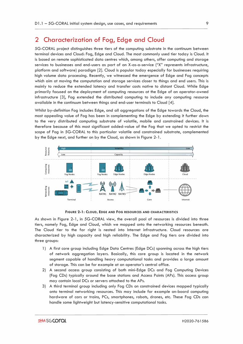
by the Edge next, and further on by the Cloud, as shown in Figure 2-1.
IoT
Terminal Access Core Internet
Fog Nodes Edge Nodes Edge Nodes CloudFog Nodes
Net
wo
rkin
gre
sou
rces
Com
puti
ng
reso
urc
es
Low
VolatilityHigh Low
HighRes
ourc
e fe
atur
es
Capacity
RAT#1 RAT#3RAT#2
FIGURE 2-1: CLOUD, EDGE AND FOG RESOURCES AND CHARACTERISTICS
As shown in Figure 2-1, in 5G-CORAL view, the overall pool of resources is divided into three
tiers, namely Fog, Edge and Cloud, which we mapped onto the networking resources beneath.
The Cloud tier to the far right is nested into Internet infrastructure. Cloud resources are
characterized by high capacity and high reliability. The Edge and Fog tiers are divided into
three groups:
1) A first core group including Edge Data Centres (Edge DCs) spanning across the high tiers
of network aggregation layers. Basically, this core group is located in the network
segment capable of handling heavy computational tasks and provides a large amount
of storage. This can be for example at an operator’s central office.
2) A second access group consisting of both mini-Edge DCs and Fog Computing Devices
(Fog CDs) typically around the base stations and Access Points (APs). This access group
may contain local DCs or servers attached to the APs.
3) A third terminal group including only Fog CDs on constrained devices mapped typically
onto terminal networking resources. This may include for example on-board computing
hardware of cars or trains, PCs, smartphones, robots, drones, etc. These Fog CDs can
handle some lightweight but latency-sensitive computational tasks.
D1.1 – 5G-CORAL initial system design, use cases, and requirements 10
H2020-761586
2.1 Characterization of Cloud
2.1.1 Background
Huge data centres have been deployed around the world to provide processing and storage
capabilities [5]. Clients of a Cloud service are likely to pay for the service in a pay-as-you-go
manner and on-demand basis, therefore they can optimize their costs. One of the key enabling
technologies for Cloud is virtualization, which permits a better utilization of the physical resources
by abstracting the software applications from the hardware they rely upon.
2.1.2 Characterization
The National Institute of Standards and Technology (NIST) [6] defines Cloud Computing as a
model for enabling convenient, on-demand network access to a shared pool of configurable
computing resources (e.g., networks, server, storage, application and services) that can be
rapidly provisioned and released with minimal management effort or service provider
interaction. The essential characteristics that outline this model are:
• On-demand self-service: consume computing capabilities without requiring human
interaction with the service provider.
• Broad network access: capabilities are available over the network.
• Resource pooling: the computing resources are pooled to serve multiple consumers using
a multi-tenant model.
• Rapid elasticity: rapid scalability by provisioning or releasing capabilities. This is
transparent to the user.
• Measured service: the metering capability to control and optimize resources.
Regarding the level of control that the user has over the resources consumed, three service
models are defined in Cloud Computing [6]:
• Software-as-a-Service (SaaS): a user can utilize software applications accessible
through an interface. The software is maintained by the Cloud provider, without
managing the underlying network infrastructure.
• Platform-as-a-Service (PaaS): the user can access a platform running an operative
system to execute its own software applications. The user only controls applications and
hosting configuration.
• Infrastructure-as-a-Service (IaaS): this is the less constrained model. The user controls
operative systems, storage, deployed applications and possibly some networking
components (e.g. firewall).
In addition, four deployment models have been defined:
• Private Cloud: Cloud deployed for exclusive use by a single organization. The
ownership, operation and management may be executed by the same organization or a
third-party.
• Community Cloud: the Cloud infrastructure is shared by a community of organizations.
The ownership, operation and management may be performed by one or more
organizations of the community or a third party.
• Public Cloud: the Cloud infrastructure is provisioned for open use by the general public.
Owned, operated and managed by business, academic or government organizations, or
a combination of them.
• Hybrid Cloud: it combines any types of the Clouds described above.
D1.1 – 5G-CORAL initial system design, use cases, and requirements 11
H2020-761586
2.1.3 Cloud Infrastructure
Cloud resources are usually gathered in a centralized data centre where hundreds of servers,
switches, power units and other physical hardware components can be found. This huge
infrastructure can serve requests from users located even in different countries. From the
infrastructure point of view, when building a data centre for hosting the Cloud, some basic
components need to be present, namely racks, servers, switches and power supplies. A short
description of these components and their common features is presented in Table 2-1.
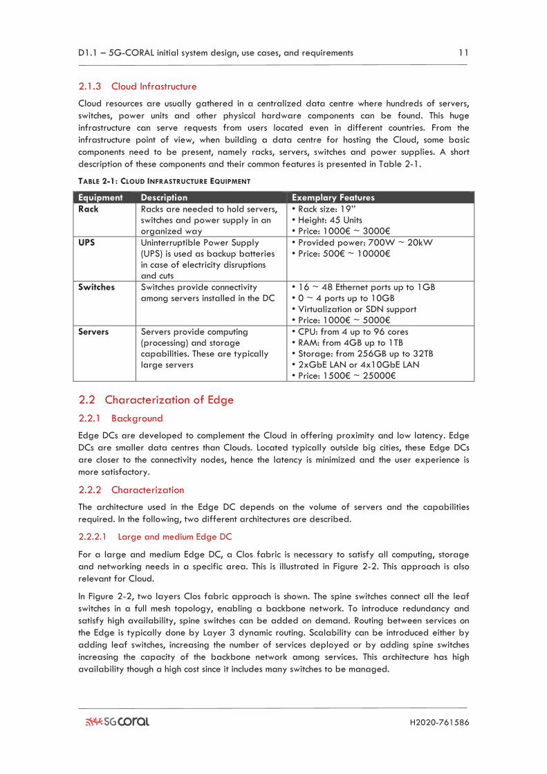
TABLE 2-1: CLOUD INFRASTRUCTURE EQUIPMENT
Equipment Description Exemplary Features
Rack Racks are needed to hold servers, switches and power supply in an organized way
• Rack size: 19’’ • Height: 45 Units • Price: 1000€ ~ 3000€
UPS Uninterruptible Power Supply (UPS) is used as backup batteries in case of electricity disruptions and cuts
• Provided power: 700W ~ 20kW • Price: 500€ ~ 10000€
Switches Switches provide connectivity among servers installed in the DC
• 16 ~ 48 Ethernet ports up to 1GB • 0 ~ 4 ports up to 10GB • Virtualization or SDN support • Price: 1000€ ~ 5000€
Servers Servers provide computing (processing) and storage capabilities. These are typically large servers
• CPU: from 4 up to 96 cores • RAM: from 4GB up to 1TB • Storage: from 256GB up to 32TB • 2xGbE LAN or 4x10GbE LAN • Price: 1500€ ~ 25000€
2.2 Characterization of Edge
2.2.1 Background
Edge DCs are developed to complement the Cloud in offering proximity and low latency. Edge
DCs are smaller data centres than Clouds. Located typically outside big cities, these Edge DCs
are closer to the connectivity nodes, hence the latency is minimized and the user experience is
more satisfactory.
2.2.2 Characterization
The architecture used in the Edge DC depends on the volume of servers and the capabilities
required. In the following, two different architectures are described.
2.2.2.1 Large and medium Edge DC
For a large and medium Edge DC, a Clos fabric is necessary to satisfy all computing, storage
and networking needs in a specific area. This is illustrated in Figure 2-2. This approach is also
relevant for Cloud.
In Figure 2-2, two layers Clos fabric approach is shown. The spine switches connect all the leaf
switches in a full mesh topology, enabling a backbone network. To introduce redundancy and
satisfy high availability, spine switches can be added on demand. Routing between services on
the Edge is typically done by Layer 3 dynamic routing. Scalability can be introduced either by
adding leaf switches, increasing the number of services deployed or by adding spine switches
increasing the capacity of the backbone network among services. This architecture has high
availability though a high cost since it includes many switches to be managed.
D1.1 – 5G-CORAL initial system design, use cases, and requirements 12
H2020-761586
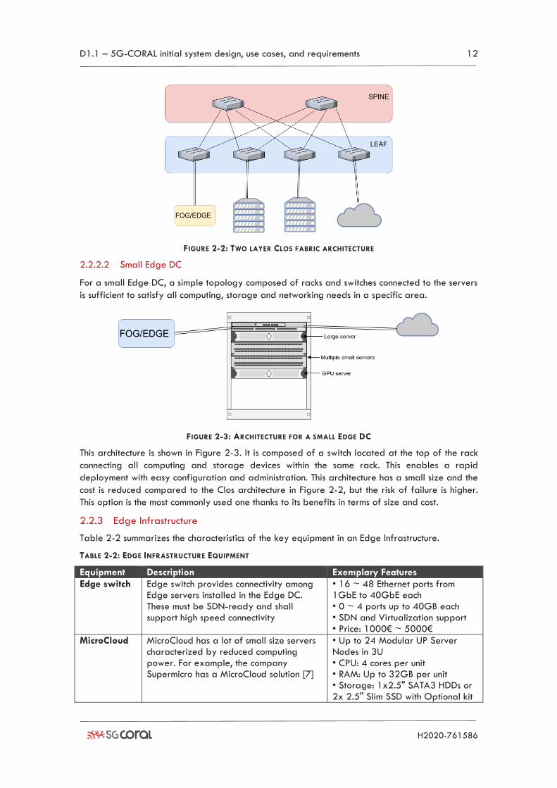
FIGURE 2-2: TWO LAYER CLOS FABRIC ARCHITECTURE
2.2.2.2 Small Edge DC
For a small Edge DC, a simple topology composed of racks and switches connected to the servers
is sufficient to satisfy all computing, storage and networking needs in a specific area.
FIGURE 2-3: ARCHITECTURE FOR A SMALL EDGE DC
This architecture is shown in Figure 2-3. It is composed of a switch located at the top of the rack
connecting all computing and storage devices within the same rack. This enables a rapid
deployment with easy configuration and administration. This architecture has a small size and the
cost is reduced compared to the Clos architecture in Figure 2-2, but the risk of failure is higher.
This option is the most commonly used one thanks to its benefits in terms of size and cost.
2.2.3 Edge Infrastructure
Table 2-2 summarizes the characteristics of the key equipment in an Edge Infrastructure.
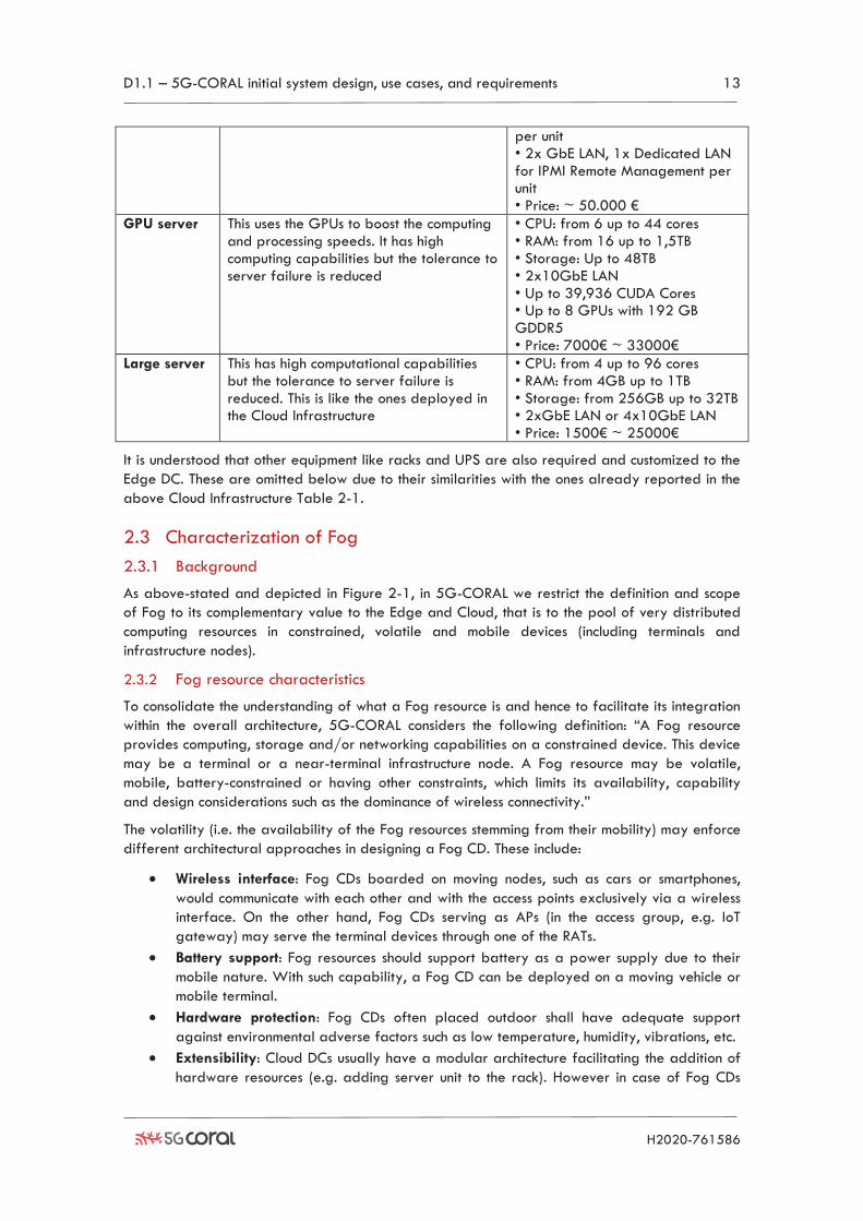
TABLE 2-2: EDGE INFRASTRUCTURE EQUIPMENT
Equipment Description Exemplary Features
Edge switch Edge switch provides connectivity among Edge servers installed in the Edge DC. These must be SDN-ready and shall support high speed connectivity
• 16 ~ 48 Ethernet ports from 1GbE to 40GbE each • 0 ~ 4 ports up to 40GB each • SDN and Virtualization support • Price: 1000€ ~ 5000€
MicroCloud MicroCloud has a lot of small size servers characterized by reduced computing power. For example, the company Supermicro has a MicroCloud solution [7]
• Up to 24 Modular UP Server Nodes in 3U • CPU: 4 cores per unit • RAM: Up to 32GB per unit • Storage: 1x2.5" SATA3 HDDs or 2x 2.5" Slim SSD with Optional kit
D1.1 – 5G-CORAL initial system design, use cases, and requirements 13
H2020-761586
per unit • 2x GbE LAN, 1x Dedicated LAN for IPMI Remote Management per unit • Price: ~ 50.000 €
GPU server This uses the GPUs to boost the computing and processing speeds. It has high computing capabilities but the tolerance to server failure is reduced
• CPU: from 6 up to 44 cores • RAM: from 16 up to 1,5TB • Storage: Up to 48TB • 2x10GbE LAN • Up to 39,936 CUDA Cores • Up to 8 GPUs with 192 GB GDDR5 • Price: 7000€ ~ 33000€
Large server This has high computational capabilities but the tolerance to server failure is reduced. This is like the ones deployed in the Cloud Infrastructure
• CPU: from 4 up to 96 cores • RAM: from 4GB up to 1TB • Storage: from 256GB up to 32TB • 2xGbE LAN or 4x10GbE LAN • Price: 1500€ ~ 25000€
It is understood that other equipment like racks and UPS are also required and customized to the
Edge DC. These are omitted below due to their similarities with the ones already reported in the
above Cloud Infrastructure Table 2-1.
2.3 Characterization of Fog
2.3.1 Background
As above-stated and depicted in Figure 2-1, in 5G-CORAL we restrict the definition and scope
of Fog to its complementary value to the Edge and Cloud, that is to the pool of very distributed
computing resources in constrained, volatile and mobile devices (including terminals and
infrastructure nodes).
2.3.2 Fog resource characteristics
To consolidate the understanding of what a Fog resource is and hence to facilitate its integration
within the overall architecture, 5G-CORAL considers the following definition: “A Fog resource
provides computing, storage and/or networking capabilities on a constrained device. This device
may be a terminal or a near-terminal infrastructure node. A Fog resource may be volatile,
mobile, battery-constrained or having other constraints, which limits its availability, capability
and design considerations such as the dominance of wireless connectivity.”
The volatility (i.e. the availability of the Fog resources stemming from their mobility) may enforce
different architectural approaches in designing a Fog CD. These include:
• Wireless interface: Fog CDs boarded on moving nodes, such as cars or smartphones,
would communicate with each other and with the access points exclusively via a wireless
interface. On the other hand, Fog CDs serving as APs (in the access group, e.g. IoT
gateway) may serve the terminal devices through one of the RATs.
• Battery support: Fog resources should support battery as a power supply due to their
mobile nature. With such capability, a Fog CD can be deployed on a moving vehicle or
mobile terminal.
• Hardware protection: Fog CDs often placed outdoor shall have adequate support
against environmental adverse factors such as low temperature, humidity, vibrations, etc.
• Extensibility: Cloud DCs usually have a modular architecture facilitating the addition of
hardware resources (e.g. adding server unit to the rack). However in case of Fog CDs
D1.1 – 5G-CORAL initial system design, use cases, and requirements 14
H2020-761586
such dynamic extension is less common due to the fixed housing. External extensions
might be possible (e.g., plugging flash storage into the USB port) but may not be
compatible with strict requirements for operation in harsh environments.
• Ad-hoc networking: Fog CDs, due to volatility and mobility, may have different
networking deployments. In addition to centralized or hierarchical designs like in the
Edge DC, Fog CDs might utilize ad-hoc network creation with various topologies (mesh,
ring, etc.) depending on the context.
2.3.3 Fog Infrastructure
The commercial implementation of Fog CDs is, in general, based on stand-alone hardware
entities combined with a software platform which allows main Fog functionality i.e. remote,
automatic software deployment, connectivity with end devices (sensors – e.g. cameras, actuators,
industrial robots) and to some extent interconnection with other Fog CDs (creating a particular
topology) via wired and/or wireless media. The capability of Fog CDs (computation, storage)
varies and depends on applications of interest but usually is much lower than the one of data
centres. Even though there are many products matching described characteristics of the Fog CD,
they lack software capabilities targeted by 5G-CORAL framework such as hardware
virtualization, remote control/management, automated software deployment and migration, etc.
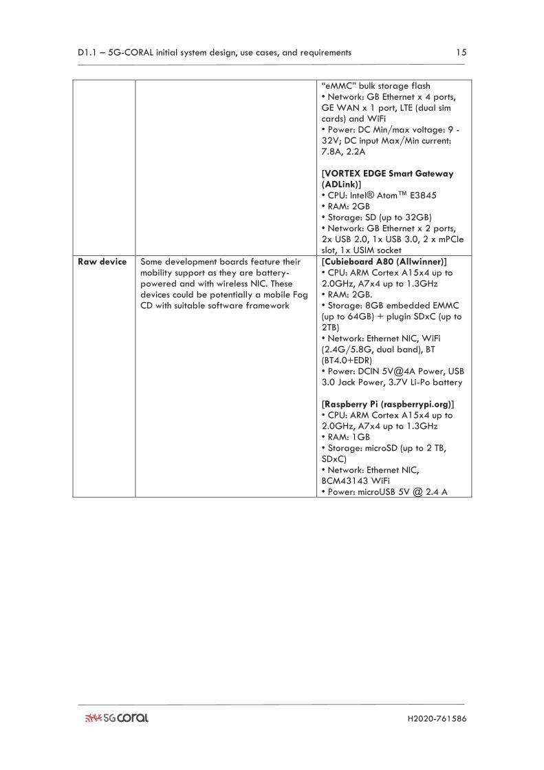
Table 2-3 provides a list of Fog products divided into two categories: (1) Complete solution,
advertised as a solution developed for Fog computing scenarios; and (2) Raw device, which
seems a suitable hardware platform to deploy Fog CD functionality. Examples of products in
each category are reported too.
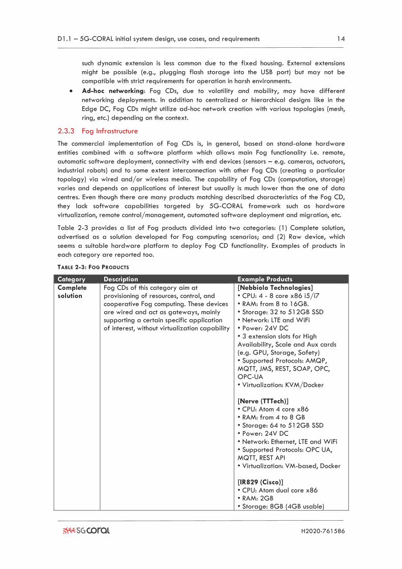
TABLE 2-3: FOG PRODUCTS
Category Description Example Products
Complete solution
Fog CDs of this category aim at provisioning of resources, control, and cooperative Fog computing. These devices are wired and act as gateways, mainly supporting a certain specific application of interest, without virtualization capability
[Nebbiolo Technologies] • CPU: 4 - 8 core x86 i5/i7 • RAM: from 8 to 16GB. • Storage: 32 to 512GB SSD • Network: LTE and WiFi • Power: 24V DC • 3 extension slots for High Availability, Scale and Aux cards (e.g. GPU, Storage, Safety) • Supported Protocols: AMQP, MQTT, JMS, REST, SOAP, OPC, OPC-UA • Virtualization: KVM/Docker [Nerve (TTTech)] • CPU: Atom 4 core x86 • RAM: from 4 to 8 GB • Storage: 64 to 512GB SSD • Power: 24V DC • Network: Ethernet, LTE and WiFi • Supported Protocols: OPC UA, MQTT, REST API • Virtualization: VM-based, Docker [IR829 (Cisco)] • CPU: Atom dual core x86 • RAM: 2GB • Storage: 8GB (4GB usable)
D1.1 – 5G-CORAL initial system design, use cases, and requirements 15
H2020-761586
“eMMC” bulk storage flash • Network: GB Ethernet x 4 ports, GE WAN x 1 port, LTE (dual sim cards) and WiFi • Power: DC Min/max voltage: 9 - 32V; DC input Max/Min current: 7.8A, 2.2A [VORTEX EDGE Smart Gateway (ADLink)] • CPU: Intel® Atom™ E3845 • RAM: 2GB • Storage: SD (up to 32GB) • Network: GB Ethernet x 2 ports, 2x USB 2.0, 1x USB 3.0, 2 x mPCIe slot, 1x USIM socket
Raw device Some development boards feature their mobility support as they are battery-powered and with wireless NIC. These devices could be potentially a mobile Fog CD with suitable software framework
[Cubieboard A80 (Allwinner)] • CPU: ARM Cortex A15x4 up to 2.0GHz, A7x4 up to 1.3GHz • RAM: 2GB. • Storage: 8GB embedded EMMC (up to 64GB) + plugin SDxC (up to 2TB) • Network: Ethernet NIC, WiFi (2.4G/5.8G, dual band), BT (BT4.0+EDR) • Power: DCIN 5V@4A Power, USB 3.0 Jack Power, 3.7V Li-Po battery [Raspberry Pi (raspberrypi.org)] • CPU: ARM Cortex A15x4 up to 2.0GHz, A7x4 up to 1.3GHz • RAM: 1GB • Storage: microSD (up to 2 TB, SDxC) • Network: Ethernet NIC, BCM43143 WiFi • Power: microUSB 5V @ 2.4 A
D1.1 – 5G-CORAL initial system design, use cases, and requirements 16
H2020-761586
3 Scenarios and Use Cases This section describes some of the use cases studied so far in the context of 5G-CORAL. These use
cases are structured in three clusters, depending on the mobility scenario, low, medium and high.
For each use case, a thorough description is provided along with an exemplary deployment
scenario. Requirements for each use case are also identified together with an initial identification
of which requirements are most impacted by 5G-CORAL.
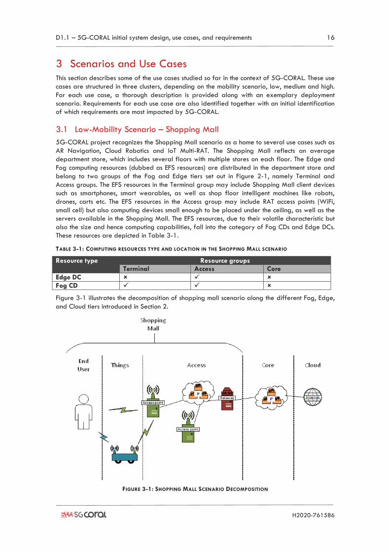
3.1 Low-Mobility Scenario – Shopping Mall
5G-CORAL project recognizes the Shopping Mall scenario as a home to several use cases such as
AR Navigation, Cloud Robotics and IoT Multi-RAT. The Shopping Mall reflects an average
department store, which includes several floors with multiple stores on each floor. The Edge and
Fog computing resources (dubbed as EFS resources) are distributed in the department store and
belong to two groups of the Fog and Edge tiers set out in Figure 2-1, namely Terminal and
Access groups. The EFS resources in the Terminal group may include Shopping Mall client devices
such as smartphones, smart wearables, as well as shop floor intelligent machines like robots,
drones, carts etc. The EFS resources in the Access group may include RAT access points (WiFi,
small cell) but also computing devices small enough to be placed under the ceiling, as well as the
servers available in the Shopping Mall. The EFS resources, due to their volatile characteristic but
also the size and hence computing capabilities, fall into the category of Fog CDs and Edge DCs.
These resources are depicted in Table 3-1.
TABLE 3-1: COMPUTING RESOURCES TYPE AND LOCATION IN THE SHOPPING MALL SCENARIO
Resource type Resource groups
Terminal Access Core
Edge DC ✓
Fog CD ✓ ✓
Figure 3-1 illustrates the decomposition of shopping mall scenario along the different Fog, Edge,
and Cloud tiers introduced in Section 2.
FIGURE 3-1: SHOPPING MALL SCENARIO DECOMPOSITION
D1.1 – 5G-CORAL initial system design, use cases, and requirements 17
H2020-761586
A variety of actors and stakeholders are involved in the Shopping Mall scenario. Table 3-2
describes the stakeholders split into three main environments: Shopping Mall, Core network and
Cloud. The Shopping Mall environment is further divided into three concentrations: “End-User”,
which utilizes available services offered by the department store, “Things”, which are mostly
volatile resources being part of EFS and finally “Access”, which constitutes a topology and more
powerful computing capacity, also part of the EFS.
TABLE 3-2: STAKEHOLDERS IDENTIFICATION FOR THE SHOPPING MALL SCENARIO
Shopping Mall Core Network
Cloud
End User Thing Access
Resource Terminal Unit Robot Access Point Backhaul Server
Core Network
Data Centre
Owner Mall Client Mall operator Retail stores
Mall operator Telco
Telco Cloud provider
3.1.1 Augmented Reality use case
AR is a powerful technology which brings new quality to the way we perceive the surrounding
world. The goal is to understand the video stream recorded by the camera of the user device
and add digital content (image or animation) on top of it in order to augment the video the end-
user is observing (e.g. from the phone’s screen). The purpose can be purely entertaining such as
gaming (e.g. Pokemon GO [8]) or utility (assistance [9], navigation [10]). It is the latter
application of AR that we are focusing on hereafter.
We are aiming at providing a continuous indoor AR navigation experience for the clients in the
Shopping Mall. The objective is to augment the user recorded video frames with a navigation
arrow similar to the popular car navigation application. The user will see a guiding line
grounded in the real-world image displayed on his screen so that it will remind a real object, i.e.
a pointer, to the desired destination. Moreover, users will be able to see shop promotions on their
screen whenever they pass by the store. These special offers will enhance the shopping
experience for the mall’s client.
The key enabling technology used to bring seamless navigation and shopping experience is
Image Recognition (IR) [11]. It allows to identify filmed objects and place an arrow for directions
in the right spot on the screen. The process requires comparing frames of the recorded video
stream with existing image base of the area or object being filmed. Better results require
maintaining a database with more prerecorded images which may lead to extended size of the
mentioned database. Current solutions deal with this problem by storing image base in the data
centre. This, however, increases the end-to-end delay between the user and the IR engine.
Together with processing delay, it may disrupt the continuous experience of the user (due to some
3-5 seconds end-to-end delay).
IR techniques might be used to determine the location of a person and the direction it is facing.
However, it requires to maintain a large image set. The resultant database size and processing
power required to process the images may make it difficult to achieve satisfactory results in a
timely manner. In order to improve this process, IR can be supported by other localization
techniques such as Global Positioning System (GPS) [12] or WiFi Positioning System (WPS) [13].
Unfortunately, while GPS technology is proved to be inefficient in an indoor environment where
the satellite signal is suppressed by building’s walls, WiFi-based solutions require careful
deployment yielding 3-4 m of accuracy [14].
The environment proposed by 5G-CORAL drastically decreases the need for the video frame to
travel from the end user’s phone all the way to the remote data centre. The deployment of Fog
CDs, coupled with WiFi APs and/or LTE small cells, brings the computing power closer to the end-
D1.1 – 5G-CORAL initial system design, use cases, and requirements 18
H2020-761586
user. Networked Fog nodes, in fact, can replace the computing capability of the remote data
centre. Such distribution of computing power in the geographical area allows at the same time
distribution of the image database. Indeed, since the recognized objects (e.g. shops, landmarks)
are bound to a particular location, the image set related to that objects needs to be deployed
only in the Fog CD covering that particular area. In other words, every Fog CD will perform
computing operations of the limited area (usually equivalent to the range of the WiFi AP it is
connected to) and hence a limited number of objects.
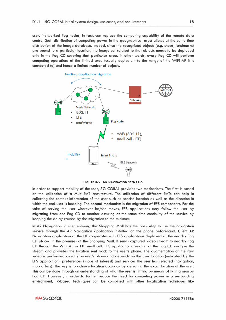
FIGURE 3-2: AR NAVIGATION SCENARIO
In order to support mobility of the user, 5G-CORAL provides two mechanisms. The first is based
on the utilization of a Multi-RAT architecture. The utilization of different RATs can help in
collecting the context information of the user such as precise location as well as the direction in
which the end-user is heading. The second mechanism is the migration of EFS components. For the
sake of serving the user wherever he/she moves, EFS applications may follow the user by
migrating from one Fog CD to another assuring at the same time continuity of the service by
keeping the delay caused by the migration to the minimum.
In AR Navigation, a user entering the Shopping Mall has the possibility to use the navigation
service through the AR Navigation application installed on the phone beforehand. Client AR
Navigation application at the UE cooperates with EFS applications deployed at the nearby Fog
CD placed in the premises of the Shopping Mall. It sends captured video stream to nearby Fog
CD through the WiFi AP or LTE small cell. EFS applications residing at the Fog CD analyze the
stream and provides the location sent back to the user’s phone. The augmentation of the raw
video is performed directly on user’s phone and depends on the user location (indicated by the
EFS application), preferences (shops of interest) and services the user has selected (navigation,
shop offers). The key is to achieve location accuracy by detecting the exact location of the user.
This can be done through an understanding of what the user is filming by means of IR in a nearby
Fog CD. However, in order to further reduce the need for computing power in a surrounding
environment, IR-based techniques can be combined with other localization techniques like
D1.1 – 5G-CORAL initial system design, use cases, and requirements 19
H2020-761586
Bluetooth Low Energy (BLE) beacons. Beacons, distributed in known locations around the mall, will
broadcast unique information (beacon ID) to all surrounding UEs. Once detected, the UE could
attach this information to the video stream sent to the Fog CD. This additional information can
later help the system to identify the more precise location of the user with less computational
overhead.
The AR Navigation use case will constitute a blend of networking and computing technologies, as
illustrated in Figure 3-2. These include:
• User Equipment (UE): through the AR client application, it will capture the video and
then send its frames to the EFS for further analysis. It will also display the augmented
video to the user.
• Beacons: the beacon’s ID is broadcast via a BLE network. The ID can be incorporated
into the data stream by UE’s AR application and then analysed by the system residing at
the interconnected Fog CDs for proper localization of the user.
• WiFi AP/LTE small cell: this point of attachment is used for connecting UE and residing
AR application to the EFS. UE must rely on reliable and high throughput connectivity to
send and receive data streams to and from the Fog CD. A combination of these access
technologies may be devised.
• Fog CD: this is the vessel for the IR application and, at the same time, the basic EFS
resource. Fog CDs are ‘lightweight’ computing devices (e.g. A80 [15]) that can support
overlaying IR application. However, when connected to a network, they can distribute
computing tasks among themselves to ensure load balancing.
• Backhaul network: this network interconnects the Fog CDs with each other. It can be
based on wired (e.g. Ethernet) or wireless (e.g. WiFi, mmWave) solutions depending on
the nature of Fog CDs (static/mobile), ease of deployment (wireless approach allows
ad-hoc network establishment) and costs.
• Gateway: this supports connectivity between the local EFS and the Cloud. It allows for
example on-demand deployment of AR engine on the local Fog CDs.
The UE is the most dynamic component of the AR Navigation scenario. It uses various RATs to
fulfill use case’s goals and can be divided into two parts:
• Higher Reliability and Throughput: the UE, through the use of multiple RATs (e.g. WiFi,
LTE) may exchange information with Fog CDs at higher throughput and higher reliability.
• Higher Accuracy Localisation: through the use of beacons, the UE (and later the EFS)
can determine its rough position or, in other words, proximity to landmarks marked with
beacon technology. Together with possible WiFi triangulation approach (in addition to IR
technique), it can provide better localization results.
3.1.2 Cloud Robotics use case
Cloud Robotics is a field of robotics that leverages and integrates Cloud computing, Cloud
storage, and other Internet technologies, into industrial and commercial applications. Cloud
technologies enable robot systems to be endowed with powerful capability by leveraging the
powerful computation, storage, and communication resources available in the Cloud.
Consequently, it is possible to build lightweight, low cost, and smarter robots by placing an
intelligent brain in the Cloud which offers a converged infrastructure that can be also used to
share services and information from various robots or agents. To that end, a Cloud for robots
shall support [16] the sharing of object data between various robots and agents connected to the
Cloud, such as images, maps, robot outcomes, trajectories, and control policies. Moreover, on-
demand provisioning of parallel computing resources is needed for motion planning, task
planning, multi-robot collaboration, scheduling and coordination of the robotic system. Finally, on-
D1.1 – 5G-CORAL initial system design, use cases, and requirements 20
H2020-761586
demand human guidance and assistance, via also augmented human-robot interaction, is
required for evaluation and error recovery.
Though robots can benefit from various advantages of Cloud computing, this presents several
limitations when applied to the Cloud Robotics field. Cloud facilities traditionally reside far away
from the robots and while the Cloud providers can enforce SLAs in their infrastructure, very little
can be ensured in the network between the robots and the Cloud. As a result, Cloud-based
applications can suffer from high-latency or unpredictable jitter in the network. For instance,
controlling a robot’s motion which relies heavily on sensors and feedback of controller is
extremely challenging without assured network performance (especially when the traffic
traverses many Internet Service Providers – ISPs). Indeed, a fault in the network could leave the
robot brainless and out of control. For that reason, tasks involving real-time execution require
nowadays either on-board processing or a dedicated infrastructure close to the robots. The
former solution is usually adopted when few robots are deployed in a given area and the cost
of installing a dedicated Cloud-like infrastructure on-site is prohibitive compared to the on-board
processing. In this case, robot capabilities are typically more limited compared to a Cloud-based
solution. The latter solution instead is usually adopted when many cooperative robots are
deployed in the same area and the benefits of Cloud computing in terms of coordination
overcome the costs of deploying a dedicated computing and networking infrastructure. This is the
case of automatized warehouses where hundreds of mobile platforms are employed to move
pallets. Notwithstanding, the two solutions are a palliative for today’s Cloud Robotics and none
of them can provide all the Cloud computing benefits, including the usage of a converged
infrastructure for sharing services and information.
Computing and networking resources sprout in any location reaching a pervasive presence in
today’s environments. Devices like computers, laptops, APs, routers, base stations, smartphone,
etc. are all around us, however their usage is limited (and restricted) to the sole and unique
purpose they have been built for. This leads to a huge amount of independent and not
integrated resources. Robots operating in a certain area could potentially make use of those
resources to accomplish distinct tasks, especially the ones with stringent latency requirements, and
take advantage of the services and information available locally. To exemplify such concept, we
consider a Shopping Mall environment which also serves as our Cloud Robotics reference
scenario. A Shopping Mall traditionally comprises a variegate set of computing and networking
resources, spanning from wireless and wired infrastructure (e.g., 802.11 APs, femto-cell, Ethernet
backbone, etc.) to sensors (e.g., fire alarm, temperature, security cameras, etc.) and computing
facilities (e.g., server room). Such heterogeneity presents a great chance for enhancing robot
capabilities without the need of deploying an ad-hoc infrastructure. By hosting the brain close to
the robot, proper performance can be ensured on the network and local context information as
well as multiple connectivity options available on-site can be leveraged to accomplish complex
tasks. However, to keep the benefits provided by the consolidated infrastructure at Cloud level,
Cloud Robotics also require a converged platform in the Edge and Fog tiers.
For the Cloud Robotics use case, we envision two scenarios in the Shopping Mall:
1. In the first scenario, the robots are in charge of keeping clean the floors in common
areas of the Shopping Mall, thus providing a cleaning service;
2. In the second scenario, the robots provide synchronised delivery of goods within the
Shopping Mall building to restock the supplies of the several shops.
These scenarios require the real-time feeding of the robots with multiple inputs and data about
the environment. For instance, to detect the dirty areas to clean as well as the various spills that
regularly occur within the Shopping Mall, the robotic application needs to process the video
streams from multiple cameras distributed across the Shopping Mall building. Since multiple
D1.1 – 5G-CORAL initial system design, use cases, and requirements 21
H2020-761586
cameras are already available in the Shopping Mall for security reasons, there is no need to
deploy ad-hoc cameras for the robot which in turn may process the raw video data available in
the infrastructure at the Edge and Fog. Raw video is hence collected at the Edge and Fog
computing platform and made available to the robotic application which can further process it
via video analytics techniques to identify the areas to clean in a timely manner. Once a dirty
area/spill has been positively identified, the robotic application necessitates an indoor
navigation system to guide the cleaning robot to the precise location of the point of interest. In
addition, the cleaning application may also leverage context information data available locally
to estimate the number of people present along the path to be followed by the robot. This allows
the brain to decide whether performing the cleaning operation can be risky (or not convenient) if
some areas are particularly crowded and may hamper robot’s movements. Finally, the brain
residing in the EFS guides and instructs the robot to execute the cleaning task.
The second scenario builds on top of the first one and contemplates multiple cooperating robots
for resupplying the different shops. Data related to the stock level of each shop is collected and
analysed at the EFS and is used to determine which good needs to be delivered to which shop.
Some items may be too large for one robot alone and would require the synchronised operation
of two or more robots to carry it. Thanks to the vicinity of the brain to the robots, it is hence
possible to achieve tight coordination between the robots. Remarkably, the same navigation
system and localisation service can be used to guide the robots to the shops without the need of
deploying them twice.
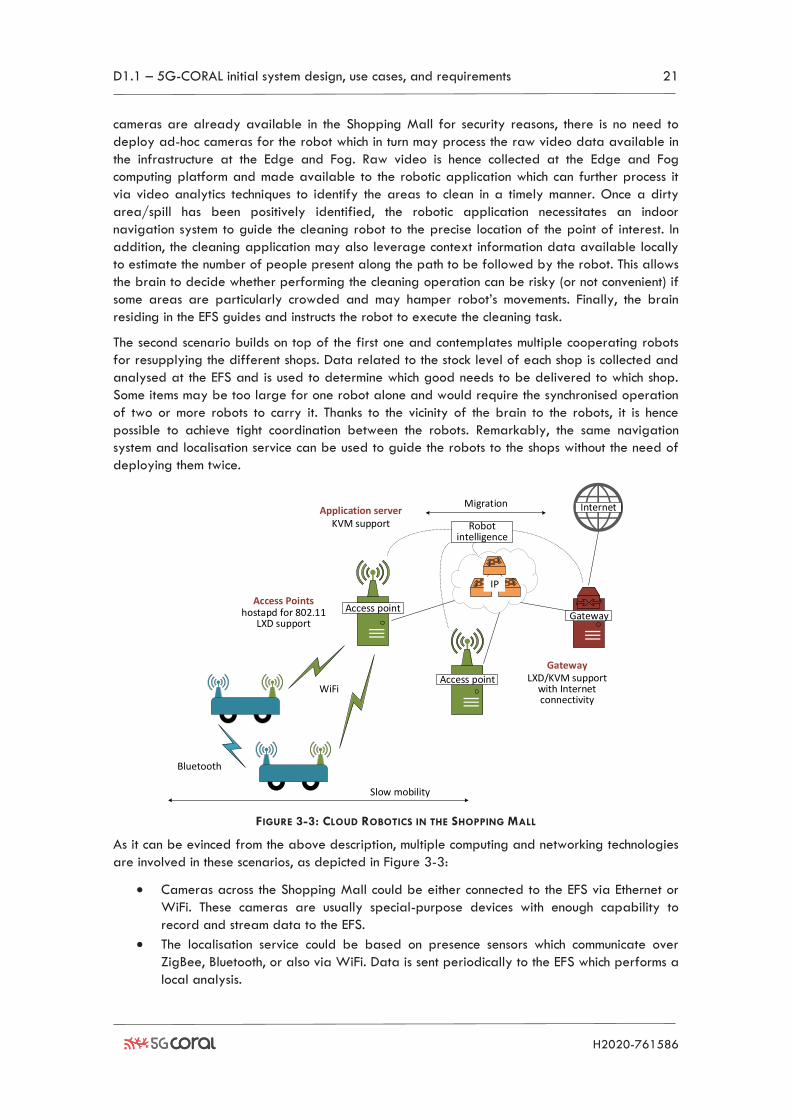
FIGURE 3-3: CLOUD ROBOTICS IN THE SHOPPING MALL
As it can be evinced from the above description, multiple computing and networking technologies
are involved in these scenarios, as depicted in Figure 3-3:
• Cameras across the Shopping Mall could be either connected to the EFS via Ethernet or
WiFi. These cameras are usually special-purpose devices with enough capability to
record and stream data to the EFS.
• The localisation service could be based on presence sensors which communicate over
ZigBee, Bluetooth, or also via WiFi. Data is sent periodically to the EFS which performs a
local analysis.
WiFi
Bluetooth
Access pointGateway
Internet
Robot intelligence
Access point
Migration
Slow mobility
IP
Application serverKVM support
Access Pointshostapd for 802.11
LXD support
GatewayLXD/KVM support
with Internet connectivity
D1.1 – 5G-CORAL initial system design, use cases, and requirements 22
H2020-761586
• Robots connect to the EFS via WiFi and/or LTE. In addition, robots may have Bluetooth
chipsets for local connectivity.
• Video processing requires powerful computing platforms with video accelerators (i.e.,
GPU) to perform the necessary analytics.
• Localisation and navigation services instead require parallel computing depending on
the amount of data (i.e., x86 servers).
• Robots and access points may offer limited computing capabilities (e.g., ARM boards)
that can be used e.g. to instantiate networking functions (e.g., WiFi APs, D2D).
All these resources need to be integrated into the same EFS platform. For the cleaning task, each
component (cameras, sensors, robots) communicates via different RATs which are blended
together for accomplishing a more complex task. A clear example of such multi-RAT cooperation
is the localisation service which can leverage multiple connectivity technologies to determine the
position of the robots. This is of particular relevance given the well-known shortcomings of GPS
when applied in indoor environments and the impossibility for the robots to rely on GPS signal
for the navigation in the Shopping Mall.
Furthermore, the robot requires multiple RATs simultaneously active to achieve the desired
synchronization level for jointly delivering large items. For instance, Bluetooth connectivity can be
used for the feedback control loop between the different spatially-close robots. Low latency and
jitter are critical requirements to keep the robots aligned and synchronised when moving.
Therefore, a direct communication (no hops) between the robots is desirable. A network-assisted
D2D mechanism is hence required to be able to perform the Bluetooth pairing between the
different robots, especially considering that different robot formations may occur at various times
(e.g., a formation of two, three, or more robots require different pairing combinations). To
achieve that, the Bluetooth pairing may use the primary Wi-Fi/LTE channel to initiate and
configure the D2D communication.
3.1.3 IoT Multi-RAT use case
IoT has emerged as a hot topic in both industry and academia in recent years. Everything is
expected to be connected in the IoT era, from critical infrastructures to consumer devices.
According to Ericsson’s mobility report [17], around 29 billion connected devices are forecast by
2022, of which around 18 billion will be related to IoT. IoT becomes one key enabler for
digitalization, which will empower the society and people with the intelligence driven by the big
amount of digital data collected.
The IoT connectivity infrastructure needs to be extremely scalable and cost-efficient to cope with
the connections of billions of IoT devices. Today’s wireless system design is mainly optimized to
deliver high-performance mobile broadband services to serve human needs. It is difficult to
assume that the same design paradigm would achieve the required scalability and cost
efficiency for IoT connectivity. Another challenge is that there are so many radio technologies
and standards for IoT connectivity, such as Narrowband IoT (NB-IoT), Long Term Evolution
category M1 (LTE-M), BLE, ZigBee, Sigfox, Long Range (LoRa), to name a few. They are
designed to cover different IoT use cases with different requirements on performance and cost
level. Many IoT scenarios, e.g. smart factory and smart building, require supporting several use
cases at the same time. Only one technology usually cannot fulfil such requirements. Therefore,
parallel networks have to be deployed in such scenarios. This can drive up the network costs
significantly.
In this 5G-CORAL use case, the main idea is to investigate the possibility to have one radio
network infrastructure (instead of parallel network deployments) to serve multiple IoT RATs. The
IoT baseband functions are centralized and cloudified to an Edge Cloud environment. The main
D1.1 – 5G-CORAL initial system design, use cases, and requirements 23
H2020-761586
benefits are increasing network flexibility, reducing network cost and increasing scalability. In
5G-CORAL, we refer to this use case as IoT Multi-RAT use case.
Essentially, we are investigating the possibility to implement the Cloud-RAN (C-RAN) concept with
multiple IoT RATs. Cloud-RAN has been proposed as a concept which can potentially increase
network flexibility and reduce the network Total Cost of Ownership (TCO) [18]. It can also
benefit network performance by increased coordination possibilities. Today, Cloud-RAN is still on
a concept level, because it is deemed difficult to implement due to complexity and reliability
issues. The terminology of C-RAN today refers more to Centralized-RAN, instead of Cloud-RAN.
In the literature, the efforts mainly from academia have tried to test the Cloud-RAN concept for
a single 3GPP technology such as LTE, e.g. [19]. In this use case, we push the state of the art
further to address multiple technologies including both 3GPP and non-3GPP technologies, as well
as connecting it to the new Edge/Fog computing paradigm in 5G-CORAL.
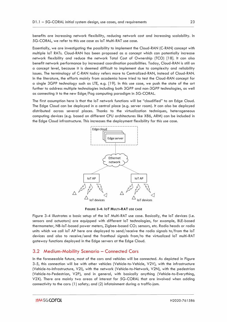
The first assumption here is that the IoT network functions will be “cloudified” to an Edge Cloud.
The Edge Cloud can be deployed in a central place (e.g. server room). It can also be deployed
distributed across several places. Thanks to the virtualization techniques, heterogeneous
computing devices (e.g. based on different CPU architectures like X86, ARM) can be included in
the Edge Cloud infrastructure. This increases the deployment flexibility for this use case.
FIGURE 3-4: IOT MULTI-RAT USE CASE
Figure 3-4 illustrates a basic setup of the IoT Multi-RAT use case. Basically, the IoT devices (i.e.
sensors and actuators) are equipped with different IoT technologies, for example, BLE-based
thermometer, NB-IoT-based power meters, Zigbee-based CO2 sensors, etc. Radio heads or radio
units which we call IoT AP here are deployed to send/receive the radio signals to/from the IoT
devices and also to receive/send the fronthaul signals from/to the virtualized IoT multi-RAT
gateway functions deployed in the Edge servers at the Edge Cloud.
3.2 Medium-Mobility Scenario – Connected Cars
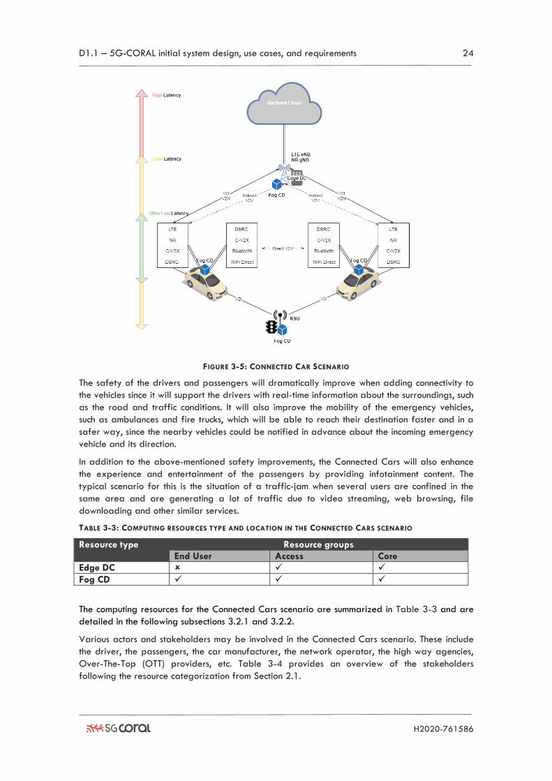
In the foreseeable future, most of the cars and vehicles will be connected. As depicted in Figure
3-5, this connection will be with other vehicles (Vehicle-to-Vehicle, V2V), with the infrastructure
(Vehicle-to-Infrastructure, V2I), with the network (Vehicle-to-Network, V2N), with the pedestrian
(Vehicle-to-Pedestrian, V2P), and in general, with basically anything (Vehicle-to-Everything,
V2X). There are mainly two areas of interest for 5G-CORAL that are involved when adding
connectivity to the cars: (1) safety; and (2) infotainment during a traffic-jam.
Edge cloud
Edge server
IoT AP
Edge server
IoT devices
Edge server
IoT AP
IoT devices
Ethernetnetwork
D1.1 – 5G-CORAL initial system design, use cases, and requirements 24
H2020-761586
FIGURE 3-5: CONNECTED CAR SCENARIO
The safety of the drivers and passengers will dramatically improve when adding connectivity to
the vehicles since it will support the drivers with real-time information about the surroundings, such
as the road and traffic conditions. It will also improve the mobility of the emergency vehicles,
such as ambulances and fire trucks, which will be able to reach their destination faster and in a
safer way, since the nearby vehicles could be notified in advance about the incoming emergency
vehicle and its direction.
In addition to the above-mentioned safety improvements, the Connected Cars will also enhance
the experience and entertainment of the passengers by providing infotainment content. The
typical scenario for this is the situation of a traffic-jam when several users are confined in the
same area and are generating a lot of traffic due to video streaming, web browsing, file
downloading and other similar services.
TABLE 3-3: COMPUTING RESOURCES TYPE AND LOCATION IN THE CONNECTED CARS SCENARIO
Resource type Resource groups
End User Access Core
Edge DC ✓ ✓
Fog CD ✓ ✓ ✓
The computing resources for the Connected Cars scenario are summarized in Table 3-3 and are
detailed in the following subsections 3.2.1 and 3.2.2.
Various actors and stakeholders may be involved in the Connected Cars scenario. These include
the driver, the passengers, the car manufacturer, the network operator, the high way agencies,
Over-The-Top (OTT) providers, etc. Table 3-4 provides an overview of the stakeholders
following the resource categorization from Section 2.1.
D1.1 – 5G-CORAL initial system design, use cases, and requirements 25
H2020-761586
TABLE 3-4: STAKEHOLDERS IDENTIFICATION FOR THE CONNECTED CARS SCENARIO
3.2.1 Safety use case
As part of the Connected Cars scenario, improvement of the safety for drivers and passengers
requires low latency communications that cannot be guaranteed by legacy networks according to
the 4G LTE end-to-end latency figures reported in Table 3-5 [20].
TABLE 3-5: 4G LTE PING RESULTS IN THE WORLD
4G LTE Ping results in the world
Best 10% 21-43 ms
Median 33-75 ms
Worst 10% 47-200 ms
In addition to the latency, the jitter and the reliability of the network are very critical for many
safety-related use cases.
In 5G-CORAL, by leveraging the deployment of Fog CDs located nearby the vehicles (e.g. Road
Side Unit (RSU), On-Board Unit (OBU)), information can be exchanged in a more quick and
distributed manner, resulting in valuable safety improvements and optimising the network
response time. In addition, the Edge DC can support operations that require more capabilities.
In addition to safety, additional new innovative services may also be envisioned such as (1)
alerting vehicles regarding the existence of a risk of collision with other vehicles or objects; (2)
assisted driving whereby the driver of the vehicle is assisted based on the environment data
received; and (3) real-time route calculator where the route is dynamically calculated based on
information published by other vehicles.
The main technologies and resources involved in this use case are:
• V2I communications, which can be done with one or more of the following technologies:
LTE, NR, Cellular V2X (C-V2X), Direct Short Range Communications (DSRC).
• V2V communications, that can be done using DSRC, C-V2X.
• OBUs need to have the computing power to run the applications and the required
hardware to support multiple RATs.
• RSUs, e.g. DSRC RSU or LTE eNB, need to have the computing power to run the
applications. RSU such as sensors or cameras can provide raw data that can be
processed to extract meaningful information, such as the traffic conditions, the road
conditions, the weather condition, etc. Both OBUs and RSUs can act as Fog CDs of the
5G-CORAL EFS. The EFS Application can exploit also Edge DC or distant central Cloud
depending on the service requirements.
3.2.2 “Infotainment during a traffic-jam” use case
As reported in [21] the global number of vehicles has reached an impressive number of one
billion of vehicles in 2010, and therefore recurrent traffic-jam with very slow-moving vehicles
happens very often. This situation is usually depicted as a negative event only but, looking at it
End User Things Access Core Network Cloud Vehicle Driver Transportation
Industry Mobile Network Operator
Mobile Network Operator
Mobile Network Operator
Vehicle Passengers
Car manufacturers
Car manufacturers
Car manufacturers
Car manufacturers
Transportation Industry
Municipality Transportation Industry
Transportation Industry
Transportation Industry
Municipality OTT player OTT player OTT player
D1.1 – 5G-CORAL initial system design, use cases, and requirements 26
H2020-761586
from another perspective, it is possible to consider the slow-moving vehicles (or the parked ones)
as a way to create business opportunities. This is because video streaming, web browsing, file
downloading and other services can be provided via the vehicle’s infotainment systems (i.e. the
set of hardware and software within cars which provides audio and/or video entertainment)
during traffic-jam. Innovative techniques like local caching in Content Delivery Networks (CDNs),
leveraging the computational and storage capacity of 5G-CORAL Fog CDs (located within
vehicles) and the available multiple RATs, could be useful to cope with increasing both capacity
demand and volume of signalling messages. In legacy mobile networks, the Quality-of-
Experience (QoE) is usually heavily affected by situations such as traffic-jams. The missing
expected QoE results in a reduction of revenues for Mobile Network Operators (MNOs) and OTT
players.
The main technologies and resources involved in this use case are listed below:
• V2N communications, that can be done with one or more of the following technologies:
LTE, NR, WiFi to near Edge DC or distant central Cloud.
• D2D communications, which can be done using LTE D2D, C-V2X, Bluetooth or WiFi direct.
• OBUs and RSUs, acting as Fog CDs, need to have the computing power to run the
applications and the required hardware to support the above-mentioned RATs.
• RSUs and OBUs could also provide high and fast storage to cache multimedia data that
can be served to the vehicles nearby.
3.3 High-Mobility Scenario – High-Speed Train
In 5G-CORAL project, a High-Speed Train scenario is considered thanks to the possibility to
leverage the commercial Taiwanese high-speed railways testbed, which connect major cities in
the island with a speed as high as 300 km per hour along more than 400 km railroad. One
envisioned goal of this scenario is to provide breakout and mobility functions on the on-board
Fog CDs that could potentially mitigate the burden of passengers’ mobility signalling on the
backhaul. Fog CDs may be deployed on-board and on-land. The computing resources for the
High-Speed Train scenario are summarized in Table 3-6.
TABLE 3-6: COMPUTING RESOURCES TYPE AND LOCATION IN THE HIGH-SPEED TRAIN SCENARIO
Resource type Resource groups
End User Access Core
Edge DC
Fog CD ✓ ✓
Various actors and stakeholders may be involved in the High-Speed Train scenario. These include
the passengers, the High-Speed Train company, the network operator, the transportation
agencies, OTT providers, etc. Table 3-7 provides an overview of the stakeholders following the
resource categorization from Section 2.1.
TABLE 3-7: STAKEHOLDERS IDENTIFICATION FOR THE HIGH-SPEED TRAIN SCENARIO
End User Things Access Core Network Cloud Passengers on board
Transportation Industry
Mobile Network Operator
Mobile Network Operator
Mobile Network Operator
Vehicle-Train High-Speed Train company
High-Speed Train company
High-Speed Train company
High-Speed Train company
Transportation Industry
Municipality Transportation Industry
Transportation Industry
Transportation Industry
Municipality OTT player OTT player OTT player
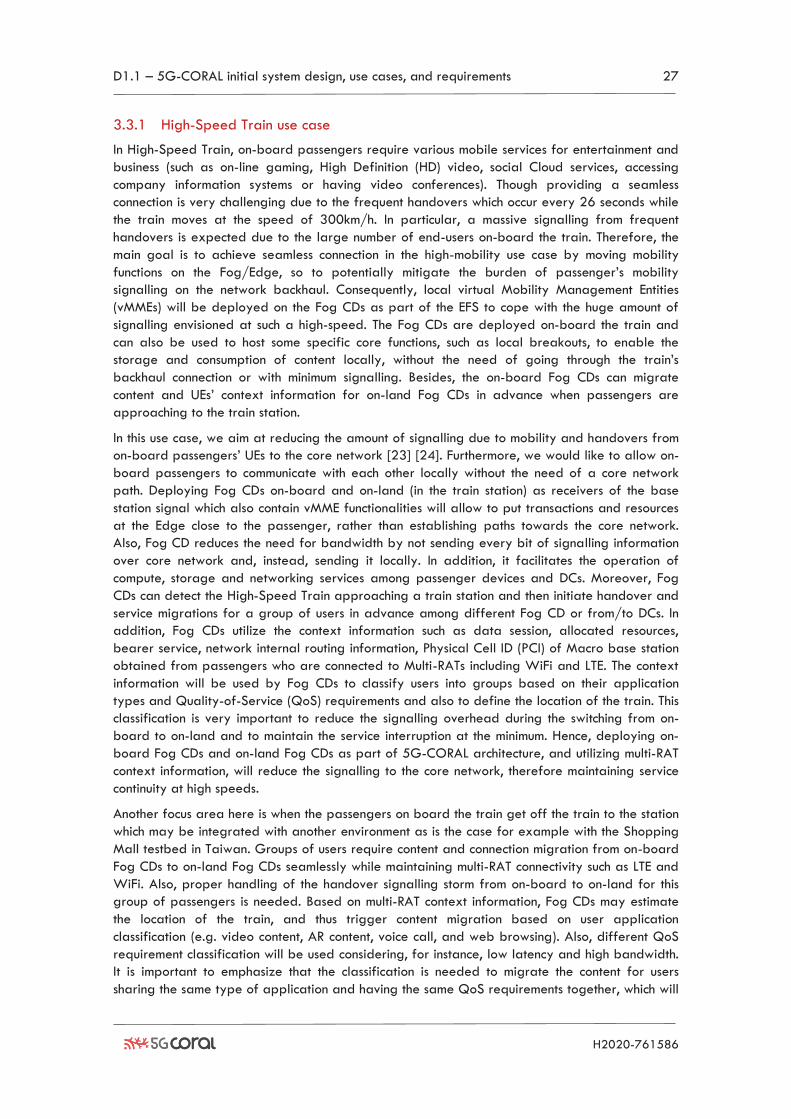
D1.1 – 5G-CORAL initial system design, use cases, and requirements 27
H2020-761586
3.3.1 High-Speed Train use case
In High-Speed Train, on-board passengers require various mobile services for entertainment and
business (such as on-line gaming, High Definition (HD) video, social Cloud services, accessing
company information systems or having video conferences). Though providing a seamless
connection is very challenging due to the frequent handovers which occur every 26 seconds while
the train moves at the speed of 300km/h. In particular, a massive signalling from frequent
handovers is expected due to the large number of end-users on-board the train. Therefore, the
main goal is to achieve seamless connection in the high-mobility use case by moving mobility
functions on the Fog/Edge, so to potentially mitigate the burden of passenger’s mobility
signalling on the network backhaul. Consequently, local virtual Mobility Management Entities
(vMMEs) will be deployed on the Fog CDs as part of the EFS to cope with the huge amount of
signalling envisioned at such a high-speed. The Fog CDs are deployed on-board the train and
can also be used to host some specific core functions, such as local breakouts, to enable the
storage and consumption of content locally, without the need of going through the train’s
backhaul connection or with minimum signalling. Besides, the on-board Fog CDs can migrate
content and UEs’ context information for on-land Fog CDs in advance when passengers are
approaching to the train station.
In this use case, we aim at reducing the amount of signalling due to mobility and handovers from
on-board passengers’ UEs to the core network [23] [24]. Furthermore, we would like to allow on-
board passengers to communicate with each other locally without the need of a core network
path. Deploying Fog CDs on-board and on-land (in the train station) as receivers of the base
station signal which also contain vMME functionalities will allow to put transactions and resources
at the Edge close to the passenger, rather than establishing paths towards the core network.
Also, Fog CD reduces the need for bandwidth by not sending every bit of signalling information
over core network and, instead, sending it locally. In addition, it facilitates the operation of
compute, storage and networking services among passenger devices and DCs. Moreover, Fog
CDs can detect the High-Speed Train approaching a train station and then initiate handover and
service migrations for a group of users in advance among different Fog CD or from/to DCs. In
addition, Fog CDs utilize the context information such as data session, allocated resources,
bearer service, network internal routing information, Physical Cell ID (PCI) of Macro base station
obtained from passengers who are connected to Multi-RATs including WiFi and LTE. The context
information will be used by Fog CDs to classify users into groups based on their application
types and Quality-of-Service (QoS) requirements and also to define the location of the train. This
classification is very important to reduce the signalling overhead during the switching from on-
board to on-land and to maintain the service interruption at the minimum. Hence, deploying on-
board Fog CDs and on-land Fog CDs as part of 5G-CORAL architecture, and utilizing multi-RAT
context information, will reduce the signalling to the core network, therefore maintaining service
continuity at high speeds.
Another focus area here is when the passengers on board the train get off the train to the station
which may be integrated with another environment as is the case for example with the Shopping
Mall testbed in Taiwan. Groups of users require content and connection migration from on-board
Fog CDs to on-land Fog CDs seamlessly while maintaining multi-RAT connectivity such as LTE and
WiFi. Also, proper handling of the handover signalling storm from on-board to on-land for this
group of passengers is needed. Based on multi-RAT context information, Fog CDs may estimate
the location of the train, and thus trigger content migration based on user application
classification (e.g. video content, AR content, voice call, and web browsing). Also, different QoS
requirement classification will be used considering, for instance, low latency and high bandwidth.
It is important to emphasize that the classification is needed to migrate the content for users
sharing the same type of application and having the same QoS requirements together, which will
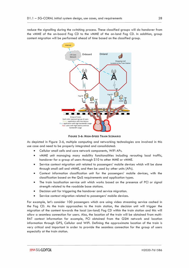
D1.1 – 5G-CORAL initial system design, use cases, and requirements 28
H2020-761586
reduce the signalling during the switching process. These classified groups will do handover from
the vMME of the on-board Fog CD to the vMME of the on-land Fog CD. In addition, group
content migration will be performed ahead of time based on the classified group.
FIGURE 3-6: HIGH-SPEED TRAIN SCENARIO
As depicted in Figure 3-6, multiple computing and networking technologies are involved in this
use case and need to be properly integrated and consolidated:
• Cellular small cells and core network components, WiFi APs.
• vMME unit managing many mobility functionalities including rerouting local traffic,
handover for a group of users through S10 to other MME or vMME.
• Service context migration unit related to passengers’ mobile devices which will be done
through small cell and vMME, and then be used by other units (APs).
• Context information classification unit for the passengers’ mobile devices, with the
classification based on the QoS requirements and application types.
• The train localisation service unit which works based on the presence of PCI or signal
strength related to the roadside base stations.
• Decision unit for triggering the handover and service migration.
• Service context migration related to passengers’ mobile devices.
For example, let’s consider 100 passengers which are using video streaming service cached in
the Fog CD. As the train approaches to the train station, the decision unit will trigger the
migration of the content towards the local (on-land) Fog CD within the train station and this will
allow a seamless connection for users. Also, the location of the train will be obtained from multi-
RAT context information for example, PCI obtained from the GSM network and location
information through GPS, Cellular and WiFi. Defining the approximate location of the train is
very critical and important in order to provide the seamless connection for the group of users
especially at the train station.
LTE Core Network
Internet
vMME
Train Direction
Onboard
Fog CD
Shopping mallLocated at the Train Station
Onland
Fog CD
vMME
Group of UsersEach color represent group of users Green: application with low latency
Blue: application with high bandwidth usageRed: users with high latency and low
bandwidth usage
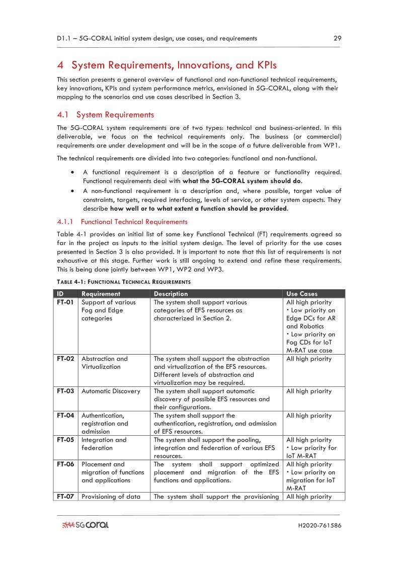
D1.1 – 5G-CORAL initial system design, use cases, and requirements 29
H2020-761586
4 System Requirements, Innovations, and KPIs This section presents a general overview of functional and non-functional technical requirements,
key innovations, KPIs and system performance metrics, envisioned in 5G-CORAL, along with their
mapping to the scenarios and use cases described in Section 3.
4.1 System Requirements
The 5G-CORAL system requirements are of two types: technical and business-oriented. In this
deliverable, we focus on the technical requirements only. The business (or commercial)
requirements are under development and will be in the scope of a future deliverable from WP1.
The technical requirements are divided into two categories: functional and non-functional.
• A functional requirement is a description of a feature or functionality required.
Functional requirements deal with what the 5G-CORAL system should do.
• A non-functional requirement is a description and, where possible, target value of
constraints, targets, required interfacing, levels of service, or other system aspects. They
describe how well or to what extent a function should be provided.
4.1.1 Functional Technical Requirements
Table 4-1 provides an initial list of some key Functional Technical (FT) requirements agreed so
far in the project as inputs to the initial system design. The level of priority for the use cases
presented in Section 3 is also provided. It is important to note that this list of requirements is not
exhaustive at this stage. Further work is still ongoing to extend and refine these requirements.
This is being done jointly between WP1, WP2 and WP3.
TABLE 4-1: FUNCTIONAL TECHNICAL REQUIREMENTS
ID Requirement Description Use Cases
FT-01 Support of various Fog and Edge categories
The system shall support various categories of EFS resources as characterized in Section 2.
All high priority Low priority on Edge DCs for AR and Robotics Low priority on Fog CDs for IoT M-RAT use case
FT-02 Abstraction and Virtualization
The system shall support the abstraction and virtualization of the EFS resources. Different levels of abstraction and virtualization may be required.
All high priority
FT-03 Automatic Discovery The system shall support automatic discovery of possible EFS resources and their configurations.
All high priority
FT-04 Authentication, registration and admission
The system shall support the authentication, registration, and admission of EFS resources.
All high priority
FT-05 Integration and federation
The system shall support the pooling, integration and federation of various EFS resources.
All high priority Low priority for IoT M-RAT
FT-06 Placement and migration of functions and applications
The system shall support optimized placement and migration of the EFS functions and applications.
All high priority Low priority on migration for IoT M-RAT
FT-07 Provisioning of data The system shall support the provisioning All high priority
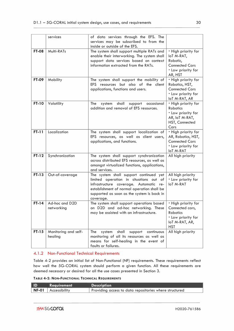
D1.1 – 5G-CORAL initial system design, use cases, and requirements 30
H2020-761586
services of data services through the EFS. The services may be subscribed to from the inside or outside of the EFS.
FT-08 Multi-RATs The system shall support multiple RATs and enable their interworking. The system shall support data services based on context information extracted from the RATs.
High priority for IoT M-RAT, Robotic, Connected Cars Low priority for AR, HST
FT-09 Mobility The system shall support the mobility of EFS resources but also of the client applications, functions and users.
High priority for Robotics, HST, Connected Cars Low priority for IoT M-RAT, AR
FT-10 Volatility The system shall support occasional addition and removal of EFS resources.
High priority for Robotics Low priority for AR, IoT M-RAT, HST, Connected Cars
FT-11 Localization The system shall support localization of EFS resources, as well as client users, applications, and functions.
High priority for AR, Robotics, HST, Connected Cars Low priority for IoT M-RAT
FT-12 Synchronization The system shall support synchronization across distributed EFS resources, as well as amongst virtualized functions, applications, and services.
All high priority
FT-13 Out-of-coverage The system shall support continued yet limited operation in situations out of infrastructure coverage. Automatic re-establishment of normal operation shall be supported as soon as the system is back in coverage.
All high priority Low priority for IoT M-RAT
FT-14 Ad-hoc and D2D networking
The system shall support operations based on D2D and ad-hoc networking. These may be assisted with an infrastructure.
High priority for Connected cars, Robotics Low priority for IoT M-RAT, AR, HST
FT-15 Monitoring and self-healing
The system shall support continuous monitoring of all its resources as well as means for self-healing in the event of faults or failures.
All high priority
4.1.2 Non-Functional Technical Requirements
Table 4-2 provides an initial list of Non-Functional (NF) requirements. These requirements reflect
how well the 5G-CORAL system should perform a given function. All these requirements are
deemed necessary or desired for all the use cases presented in Section 3.
TABLE 4-2: NON-FUNCTIONAL TECHNICAL REQUIREMENTS
ID Requirement Description
NF-01 Accessibility Providing access to data repositories where structured
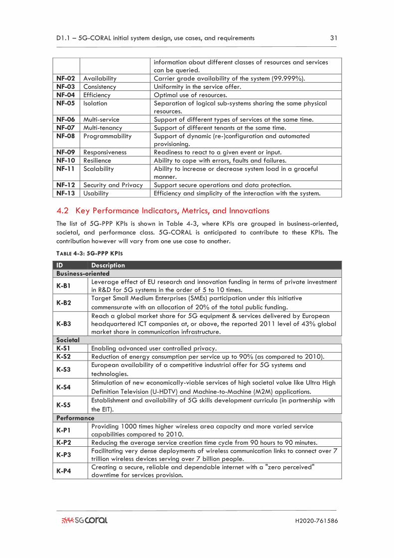
D1.1 – 5G-CORAL initial system design, use cases, and requirements 31
H2020-761586
information about different classes of resources and services can be queried.
NF-02 Availability Carrier grade availability of the system (99.999%).
NF-03 Consistency Uniformity in the service offer.
NF-04 Efficiency Optimal use of resources.
NF-05 Isolation Separation of logical sub-systems sharing the same physical resources.
NF-06 Multi-service Support of different types of services at the same time.
NF-07 Multi-tenancy Support of different tenants at the same time.
NF-08 Programmability Support of dynamic (re-)configuration and automated provisioning.
NF-09 Responsiveness Readiness to react to a given event or input.
NF-10 Resilience Ability to cope with errors, faults and failures.
NF-11 Scalability Ability to increase or decrease system load in a graceful manner.
NF-12 Security and Privacy Support secure operations and data protection.
NF-13 Usability Efficiency and simplicity of the interaction with the system.
4.2 Key Performance Indicators, Metrics, and Innovations
The list of 5G-PPP KPIs is shown in Table 4-3, where KPIs are grouped in business-oriented,
societal, and performance class. 5G-CORAL is anticipated to contribute to these KPIs. The
contribution however will vary from one use case to another.
TABLE 4-3: 5G-PPP KPIS
ID Description
Business-oriented
K-B1 Leverage effect of EU research and innovation funding in terms of private investment in R&D for 5G systems in the order of 5 to 10 times.
K-B2 Target Small Medium Enterprises (SMEs) participation under this initiative
commensurate with an allocation of 20% of the total public funding.
K-B3 Reach a global market share for 5G equipment & services delivered by European headquartered ICT companies at, or above, the reported 2011 level of 43% global market share in communication infrastructure.
Societal
K-S1 Enabling advanced user controlled privacy.
K-S2 Reduction of energy consumption per service up to 90% (as compared to 2010).
K-S3 European availability of a competitive industrial offer for 5G systems and
technologies.
K-S4 Stimulation of new economically-viable services of high societal value like Ultra High
Definition Television (U-HDTV) and Machine-to-Machine (M2M) applications.
K-S5 Establishment and availability of 5G skills development curricula (in partnership with
the EIT).
Performance
K-P1 Providing 1000 times higher wireless area capacity and more varied service capabilities compared to 2010.
K-P2 Reducing the average service creation time cycle from 90 hours to 90 minutes.
K-P3 Facilitating very dense deployments of wireless communication links to connect over 7 trillion wireless devices serving over 7 billion people.
K-P4 Creating a secure, reliable and dependable internet with a "zero perceived" downtime for services provision.
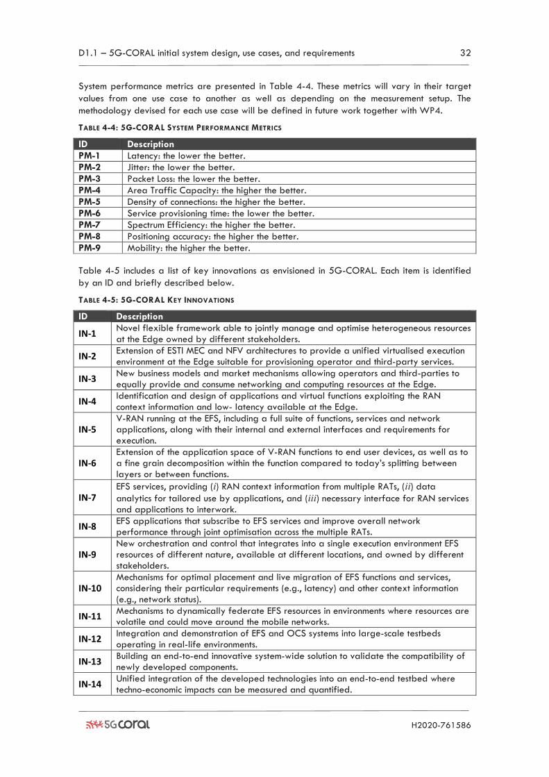
D1.1 – 5G-CORAL initial system design, use cases, and requirements 32
H2020-761586
System performance metrics are presented in Table 4-4. These metrics will vary in their target
values from one use case to another as well as depending on the measurement setup. The
methodology devised for each use case will be defined in future work together with WP4.
TABLE 4-4: 5G-CORAL SYSTEM PERFORMANCE METRICS
ID Description
PM-1 Latency: the lower the better.
PM-2 Jitter: the lower the better.
PM-3 Packet Loss: the lower the better.
PM-4 Area Traffic Capacity: the higher the better.
PM-5 Density of connections: the higher the better.
PM-6 Service provisioning time: the lower the better.
PM-7 Spectrum Efficiency: the higher the better.
PM-8 Positioning accuracy: the higher the better.
PM-9 Mobility: the higher the better.
Table 4-5 includes a list of key innovations as envisioned in 5G-CORAL. Each item is identified
by an ID and briefly described below.
TABLE 4-5: 5G-CORAL KEY INNOVATIONS
ID Description
IN-1 Novel flexible framework able to jointly manage and optimise heterogeneous resources at the Edge owned by different stakeholders.
IN-2 Extension of ESTI MEC and NFV architectures to provide a unified virtualised execution environment at the Edge suitable for provisioning operator and third-party services.
IN-3 New business models and market mechanisms allowing operators and third-parties to equally provide and consume networking and computing resources at the Edge.
IN-4 Identification and design of applications and virtual functions exploiting the RAN context information and low- latency available at the Edge.
IN-5 V-RAN running at the EFS, including a full suite of functions, services and network applications, along with their internal and external interfaces and requirements for execution.
IN-6 Extension of the application space of V-RAN functions to end user devices, as well as to a fine grain decomposition within the function compared to today’s splitting between layers or between functions.
IN-7 EFS services, providing (i) RAN context information from multiple RATs, (ii) data
analytics for tailored use by applications, and (iii) necessary interface for RAN services and applications to interwork.
IN-8 EFS applications that subscribe to EFS services and improve overall network performance through joint optimisation across the multiple RATs.
IN-9 New orchestration and control that integrates into a single execution environment EFS resources of different nature, available at different locations, and owned by different stakeholders.
IN-10 Mechanisms for optimal placement and live migration of EFS functions and services, considering their particular requirements (e.g., latency) and other context information (e.g., network status).
IN-11 Mechanisms to dynamically federate EFS resources in environments where resources are volatile and could move around the mobile networks.
IN-12 Integration and demonstration of EFS and OCS systems into large-scale testbeds operating in real-life environments.
IN-13 Building an end-to-end innovative system-wide solution to validate the compatibility of newly developed components.
IN-14 Unified integration of the developed technologies into an end-to-end testbed where techno-economic impacts can be measured and quantified.
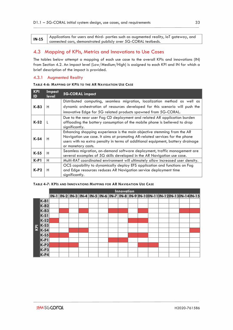
D1.1 – 5G-CORAL initial system design, use cases, and requirements 33
H2020-761586
IN-15 Applications for users and third- parties such as augmented reality, IoT gateway, and connected cars, demonstrated publicly over 5G-CORAL testbeds.
4.3 Mapping of KPIs, Metrics and Innovations to Use Cases
The tables below attempt a mapping of each use case to the overall KPIs and innovations (IN)
from Section 4.2. An impact level (Low/Medium/High) is assigned to each KPI and IN for which a
brief description of the impact is provided.
4.3.1 Augmented Reality
TABLE 4-6: MAPPING OF KPIS TO THE AR NAVIGATION USE CASE
KPI ID
Impact level
5G-CORAL impact
K-B3 H
Distributed computing, seamless migration, localization method as well as
dynamic orchestration of resources developed for this scenario will push the
innovative Edge for 5G related products spawned from 5G-CORAL.
K-S2 L Due to the near user Fog CD deployment and related AR application burden offloading the battery consumption of the mobile phone is believed to drop significantly.
K-S4 H
Enhancing shopping experience is the main objective stemming from the AR Navigation use case. It aims at promoting AR-related services for the phone users with no extra penalty in terms of additional equipment, battery drainage or monetary costs.
K-S5 H Seamless migration, on-demand software deployment, traffic management are several examples of 5G skills developed in the AR Navigation use case.
K-P1 H Multi-RAT coordinated environment will ultimately allow increased user density.
K-P2 H OCS capability to dynamically deploy EFS application and functions on Fog and Edge resources reduces AR Navigation service deployment time significantly.
TABLE 4-7: KPIS AND INNOVATIONS MAPPING FOR AR NAVIGATION USE CASE
Innovation
IN-1 IN-2 IN-3 IN-4 IN-5 IN-6 IN-7 IN-8 IN-9 IN-10 IN-11 IN-12 IN-13 IN-14 IN-15
KPI
K-B1
K-B2
K-B3
K-S1
K-S2
K-S3
K-S4
K-S5
K-P1
K-P2
K-P3
K-P4
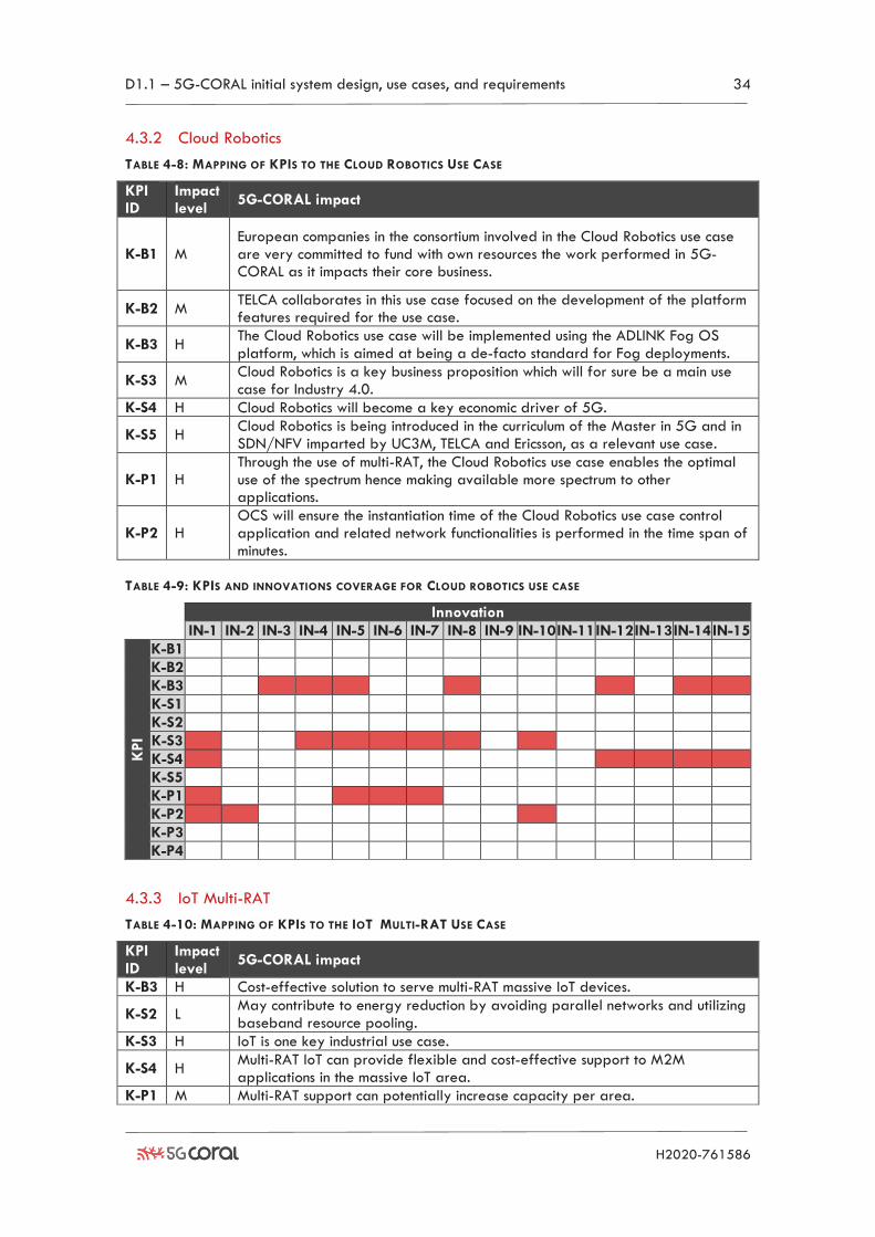
D1.1 – 5G-CORAL initial system design, use cases, and requirements 34
H2020-761586
4.3.2 Cloud Robotics
TABLE 4-8: MAPPING OF KPIS TO THE CLOUD ROBOTICS USE CASE
KPI ID
Impact level
5G-CORAL impact
K-B1 M European companies in the consortium involved in the Cloud Robotics use case are very committed to fund with own resources the work performed in 5G-CORAL as it impacts their core business.
K-B2 M TELCA collaborates in this use case focused on the development of the platform features required for the use case.
K-B3 H The Cloud Robotics use case will be implemented using the ADLINK Fog OS platform, which is aimed at being a de-facto standard for Fog deployments.
K-S3 M Cloud Robotics is a key business proposition which will for sure be a main use case for Industry 4.0.
K-S4 H Cloud Robotics will become a key economic driver of 5G.
K-S5 H Cloud Robotics is being introduced in the curriculum of the Master in 5G and in SDN/NFV imparted by UC3M, TELCA and Ericsson, as a relevant use case.
K-P1 H Through the use of multi-RAT, the Cloud Robotics use case enables the optimal use of the spectrum hence making available more spectrum to other applications.
K-P2 H OCS will ensure the instantiation time of the Cloud Robotics use case control application and related network functionalities is performed in the time span of minutes.
TABLE 4-9: KPIS AND INNOVATIONS COVERAGE FOR CLOUD ROBOTICS USE CASE
Innovation
IN-1 IN-2 IN-3 IN-4 IN-5 IN-6 IN-7 IN-8 IN-9 IN-10 IN-11 IN-12 IN-13 IN-14 IN-15
KPI
K-B1
K-B2
K-B3
K-S1
K-S2
K-S3
K-S4
K-S5
K-P1
K-P2
K-P3
K-P4
4.3.3 IoT Multi-RAT
TABLE 4-10: MAPPING OF KPIS TO THE IOT MULTI-RAT USE CASE
KPI ID
Impact level
5G-CORAL impact
K-B3 H Cost-effective solution to serve multi-RAT massive IoT devices.
K-S2 L May contribute to energy reduction by avoiding parallel networks and utilizing baseband resource pooling.
K-S3 H IoT is one key industrial use case.
K-S4 H Multi-RAT IoT can provide flexible and cost-effective support to M2M applications in the massive IoT area.
K-P1 M Multi-RAT support can potentially increase capacity per area.
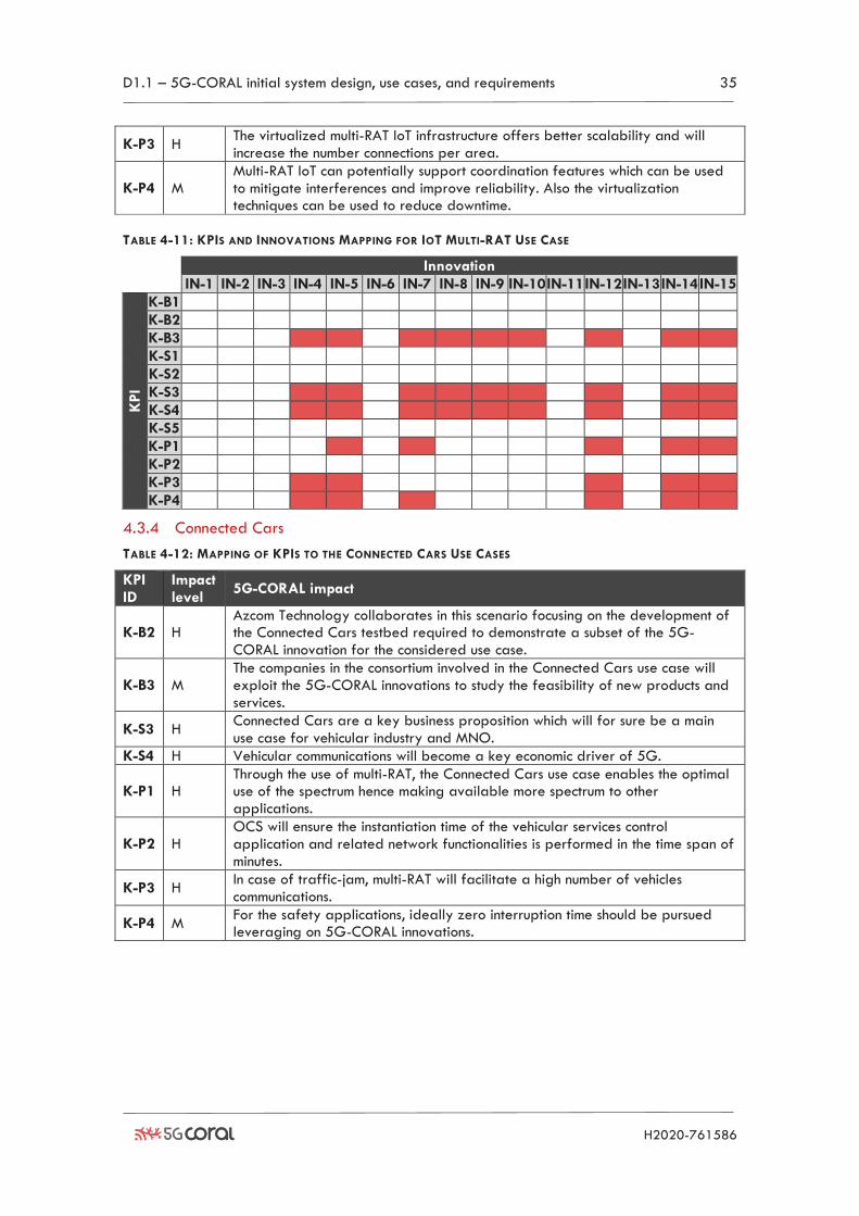
D1.1 – 5G-CORAL initial system design, use cases, and requirements 35
H2020-761586
K-P3 H The virtualized multi-RAT IoT infrastructure offers better scalability and will increase the number connections per area.
K-P4 M Multi-RAT IoT can potentially support coordination features which can be used to mitigate interferences and improve reliability. Also the virtualization techniques can be used to reduce downtime.
TABLE 4-11: KPIS AND INNOVATIONS MAPPING FOR IOT MULTI-RAT USE CASE
Innovation
IN-1 IN-2 IN-3 IN-4 IN-5 IN-6 IN-7 IN-8 IN-9 IN-10 IN-11 IN-12 IN-13 IN-14 IN-15
KPI
K-B1
K-B2
K-B3
K-S1
K-S2
K-S3
K-S4
K-S5
K-P1
K-P2
K-P3
K-P4
4.3.4 Connected Cars
TABLE 4-12: MAPPING OF KPIS TO THE CONNECTED CARS USE CASES
KPI ID
Impact level
5G-CORAL impact
K-B2 H Azcom Technology collaborates in this scenario focusing on the development of the Connected Cars testbed required to demonstrate a subset of the 5G-CORAL innovation for the considered use case.
K-B3 M The companies in the consortium involved in the Connected Cars use case will exploit the 5G-CORAL innovations to study the feasibility of new products and services.
K-S3 H Connected Cars are a key business proposition which will for sure be a main use case for vehicular industry and MNO.
K-S4 H Vehicular communications will become a key economic driver of 5G.
K-P1 H Through the use of multi-RAT, the Connected Cars use case enables the optimal use of the spectrum hence making available more spectrum to other applications.
K-P2 H OCS will ensure the instantiation time of the vehicular services control application and related network functionalities is performed in the time span of minutes.
K-P3 H In case of traffic-jam, multi-RAT will facilitate a high number of vehicles communications.
K-P4 M For the safety applications, ideally zero interruption time should be pursued leveraging on 5G-CORAL innovations.
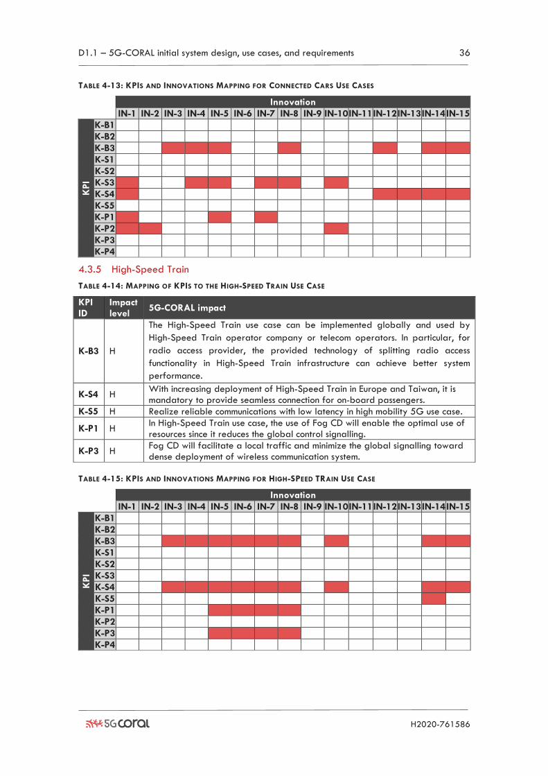
D1.1 – 5G-CORAL initial system design, use cases, and requirements 36
H2020-761586
TABLE 4-13: KPIS AND INNOVATIONS MAPPING FOR CONNECTED CARS USE CASES
Innovation
IN-1 IN-2 IN-3 IN-4 IN-5 IN-6 IN-7 IN-8 IN-9 IN-10 IN-11 IN-12 IN-13 IN-14 IN-15
KPI
K-B1
K-B2
K-B3
K-S1
K-S2
K-S3
K-S4
K-S5
K-P1
K-P2
K-P3
K-P4
4.3.5 High-Speed Train
TABLE 4-14: MAPPING OF KPIS TO THE HIGH-SPEED TRAIN USE CASE
KPI ID
Impact level
5G-CORAL impact
K-B3 H
The High-Speed Train use case can be implemented globally and used by
High-Speed Train operator company or telecom operators. In particular, for
radio access provider, the provided technology of splitting radio access
functionality in High-Speed Train infrastructure can achieve better system
performance.
K-S4 H With increasing deployment of High-Speed Train in Europe and Taiwan, it is mandatory to provide seamless connection for on-board passengers.
K-S5 H Realize reliable communications with low latency in high mobility 5G use case.
K-P1 H In High-Speed Train use case, the use of Fog CD will enable the optimal use of resources since it reduces the global control signalling.
K-P3 H Fog CD will facilitate a local traffic and minimize the global signalling toward dense deployment of wireless communication system.
TABLE 4-15: KPIS AND INNOVATIONS MAPPING FOR HIGH-SPEED TRAIN USE CASE
Innovation
IN-1 IN-2 IN-3 IN-4 IN-5 IN-6 IN-7 IN-8 IN-9 IN-10 IN-11 IN-12 IN-13 IN-14 IN-15
KPI
K-B1
K-B2
K-B3
K-S1
K-S2
K-S3
K-S4
K-S5
K-P1
K-P2
K-P3
K-P4
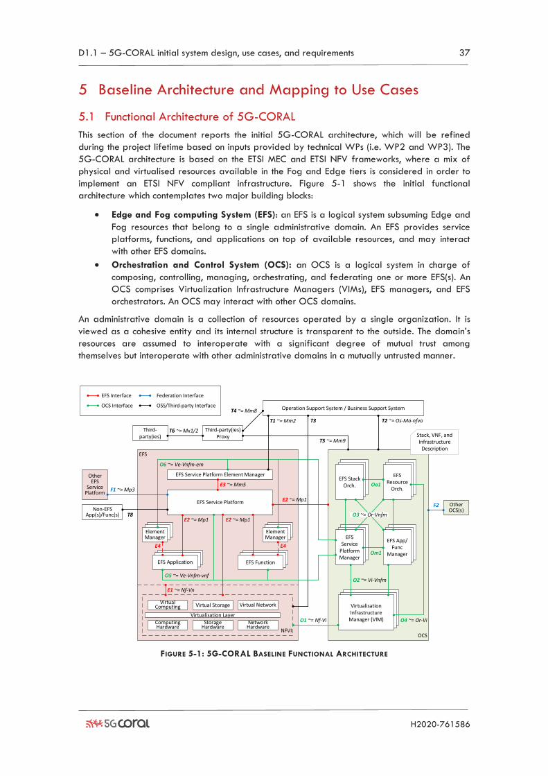
D1.1 – 5G-CORAL initial system design, use cases, and requirements 37
H2020-761586
5 Baseline Architecture and Mapping to Use Cases
5.1 Functional Architecture of 5G-CORAL
This section of the document reports the initial 5G-CORAL architecture, which will be refined
during the project lifetime based on inputs provided by technical WPs (i.e. WP2 and WP3). The
5G-CORAL architecture is based on the ETSI MEC and ETSI NFV frameworks, where a mix of
physical and virtualised resources available in the Fog and Edge tiers is considered in order to
implement an ETSI NFV compliant infrastructure. Figure 5-1 shows the initial functional
architecture which contemplates two major building blocks:
• Edge and Fog computing System (EFS): an EFS is a logical system subsuming Edge and
Fog resources that belong to a single administrative domain. An EFS provides service
platforms, functions, and applications on top of available resources, and may interact
with other EFS domains.
• Orchestration and Control System (OCS): an OCS is a logical system in charge of
composing, controlling, managing, orchestrating, and federating one or more EFS(s). An
OCS comprises Virtualization Infrastructure Managers (VIMs), EFS managers, and EFS
orchestrators. An OCS may interact with other OCS domains.
An administrative domain is a collection of resources operated by a single organization. It is
viewed as a cohesive entity and its internal structure is transparent to the outside. The domain’s
resources are assumed to interoperate with a significant degree of mutual trust among
themselves but interoperate with other administrative domains in a mutually untrusted manner.
FIGURE 5-1: 5G-CORAL BASELINE FUNCTIONAL ARCHITECTURE
OCS
EFS
EFS App/Func
Manager
Third-party(ies)
EFS Service
Platform Manager
NFVI
Computing Hardware
Storage Hardware
Network Hardware
Virtualisation Layer
Virtual Computing Virtual Storage Virtual Network
EFS Function
Virtualisation Infrastructure
Manager (VIM)
Operation Support System / Business Support System
Third-party(ies)Proxy
Other EFS
Service Platform
EFS Resource
Orch.
Other OCS(s)
EFS Interface
OCS Interface
Federation Interface
OSS/Third-party Interface
O1 ~= Nf-Vi
O2 ~= Vi-Vnfm
O4 ~= Or-Vi
E1 ~= Nf-Vn
F1 ~= Mp3
T1 ~= Mm2 T2 ~= Os-Ma-nfvo
T5 ~= Mm9
T3
T4 ~= Mm8
T6 ~= Mx1/2Stack, VNF, and Infrastructure
Description
E4
O5 ~= Ve-Vnfm-vnf
EFS Application
F2
Element Manager
E4
Element Manager
E2 ~= Mp1
E3 ~= Mm5
O6 ~= Ve-Vnfm-em
EFS Service Platform Element Manager
EFS Service Platform
E2 ~= Mp1T8
Non-EFS App(s)/Func(s)
E2 ~= Mp1
EFS Stack Orch.
Om1
O3 ~= Or-Vnfm
Oo1
D1.1 – 5G-CORAL initial system design, use cases, and requirements 38
H2020-761586
The EFS comprises three main elements:
• Service Platform: a logical data services exchange platform within EFS consisting of (i)
data storage to keep the collected information from applications/functions and
Edge/Fog resources, and (ii) communication protocol to gather/provide information
from/to applications/functions and Edge/Fog resources.
• Function: a function is a computing task comprised by at least one atomic entity
deployed in EFS for networking purposes. An atomic entity is defined as an
unpartitionable computing task executed in the EFS.
• Application: an application is a computing task comprised by at least one atomic entity
deployed in EFS for consumption by end users and third parties.
According to the ETSI NFV architecture, each of the EFS Applications, Functions and Services may
have an Element Manager which is in charge of applying the configuration and management
policies as defined by the EFS Manager at the OCS (interface O6, functional similar to ETSI NFV
Ve-Vnfm-em). The Element Manager of the EFS Service Platform partially plays the role of the
ETSI MEC Platform Manager [22] since its scope is limited to EFS service-related management
only (e.g., policies configuration). Instead, the lifecycle management of the applications and
functions is the responsibility of the OCS. The different EFS components are designed to run in a
plethora of devices, with different capacities and features. These include terminals and access
nodes in the Fog, and more capable servers located at the Edge.
The OCS design follows the ETSI NFV architecture and comprises the following components:
• Virtualization Infrastructure Manager (VIM): a VIM comprises the functionalities that
are used to control and manage the interaction of the EFS service platforms, functions,
and applications with the Edge and Fog resources under its authority, as well as their
virtualisation. Multiple VIMs may be deployed to control and manage distinct
virtualization substrates or administrative domains.
• EFS Manager: an EFS Manager is responsible for the lifecycle management (e.g.
instantiation, update, query, scaling, termination) of the service platforms, functions, and
applications in the EFS. Multiple EFS Managers may be deployed to manage distinct
components of the EFS (e.g., service platforms, functions, and applications) whereas each
EFS Manager may manage a single service platform/function/application or a multiple
of these.
• EFS Orchestrator: an EFS Orchestrator is in charge of orchestration and management of
Edge and Fog resources and composing the EFS. An EFS Orchestrator comprises an EFS
Resource Orchestrator and an EFS Stack Orchestrator.
• EFS Resource Orchestrator: an EFS Resource Orchestrator supports accessing the Edge
and Fog resources in an abstracted manner independently of any VIMs, as well as
governance of service platform/function/application instances sharing resources in the
EFS.
• EFS Stack Orchestrator: an EFS Stack Orchestrator is responsible for the EFS stack
lifecycle management operations such as on-boarding, instantiating, scaling, updating,
querying, and terminating a stack.
• EFS Stack: an EFS stack can be viewed architecturally as a forwarding graph of
functions and/or application interconnected by supporting Edge and Fog resources
and/or service platforms.
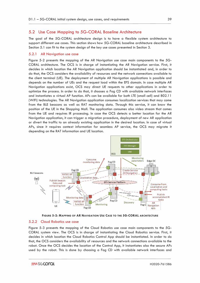
D1.1 – 5G-CORAL initial system design, use cases, and requirements 39
H2020-761586
5.2 Use Case Mapping to 5G-CORAL Baseline Architecture
The goal of the 5G-CORAL architecture design is to have a flexible system architecture to
support different use cases. This section shows how 5G-CORAL baseline architecture described in
Section 5.1 can fit to the system design of the key use cases presented in Section 3.
5.2.1 AR Navigation use case
Figure 5-2 presents the mapping of the AR Navigation use case main components to the 5G-
CORAL architecture. The OCS is in charge of instantiating the AR Navigation service. First, it
decides in which location the AR Navigation application should be instantiated and, in order to
do that, the OCS considers the availability of resources and the network connections available to
the client terminal (UE). The deployment of multiple AR Navigation applications is possible and
depends on the number of UEs and the request load within the EFS domain. In case multiple AR
Navigation applications exist, OCS may direct UE requests to other applications in order to
optimize the process. In order to do that, it chooses a Fog CD with available network interfaces
and instantiates a virtual AP function. APs can be available for both LTE (small cell) and 802.11
(WiFi) technologies. The AR Navigation application consumes localization services that may come
from the BLE beacons as well as RAT monitoring data. Through this service, it can know the
position of the UE in the Shopping Mall. The application consumes also video stream that comes
from the UE and requires IR processing. In case the OCS detects a better location for the AR
Navigation application, it can trigger a migration procedure, deployment of new AR application
or divert the traffic to an already existing application in the desired location. In case of virtual
APs, since it requires context information for seamless AP service, the OCS may migrate it
depending on the RAT information and UE location.
FIGURE 5-2: MAPPING OF AR NAVIGATION USE CASE TO THE 5G-CORAL ARCHITECTURE
5.2.2 Cloud Robotics use case
Figure 5-3 presents the mapping of the Cloud Robotics use case main components to the 5G-
CORAL system view. The OCS is in charge of instantiating the Cloud Robotics service. First, it
decides in which location the Cloud Robotics Control App should be instantiated. In order to do
that, the OCS considers the availability of resources and the network connections available to the
robot. Once the OCS decides the location of the Control App, it instantiates also the secure APs
used by the robot. This is done by choosing a Fog CD with available network interfaces and
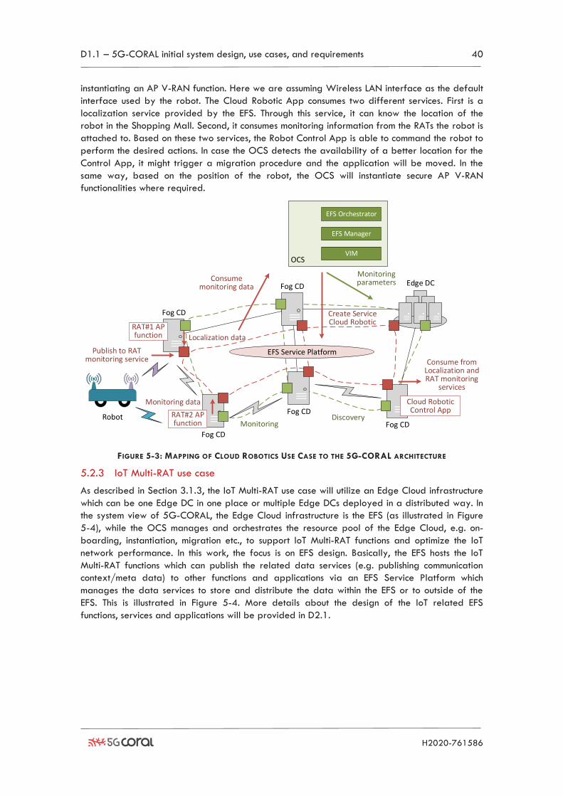
D1.1 – 5G-CORAL initial system design, use cases, and requirements 40
H2020-761586
instantiating an AP V-RAN function. Here we are assuming Wireless LAN interface as the default
interface used by the robot. The Cloud Robotic App consumes two different services. First is a
localization service provided by the EFS. Through this service, it can know the location of the
robot in the Shopping Mall. Second, it consumes monitoring information from the RATs the robot is
attached to. Based on these two services, the Robot Control App is able to command the robot to
perform the desired actions. In case the OCS detects the availability of a better location for the
Control App, it might trigger a migration procedure and the application will be moved. In the
same way, based on the position of the robot, the OCS will instantiate secure AP V-RAN
functionalities where required.
FIGURE 5-3: MAPPING OF CLOUD ROBOTICS USE CASE TO THE 5G-CORAL ARCHITECTURE
5.2.3 IoT Multi-RAT use case
As described in Section 3.1.3, the IoT Multi-RAT use case will utilize an Edge Cloud infrastructure
which can be one Edge DC in one place or multiple Edge DCs deployed in a distributed way. In
the system view of 5G-CORAL, the Edge Cloud infrastructure is the EFS (as illustrated in Figure
5-4), while the OCS manages and orchestrates the resource pool of the Edge Cloud, e.g. on-
boarding, instantiation, migration etc., to support IoT Multi-RAT functions and optimize the IoT
network performance. In this work, the focus is on EFS design. Basically, the EFS hosts the IoT
Multi-RAT functions which can publish the related data services (e.g. publishing communication
context/meta data) to other functions and applications via an EFS Service Platform which
manages the data services to store and distribute the data within the EFS or to outside of the
EFS. This is illustrated in Figure 5-4. More details about the design of the IoT related EFS
functions, services and applications will be provided in D2.1.
Fog CD
Fog CD
Edge DC
Fog CD
Fog CD
Fog CD
EFS Service PlatformPublish to RAT monitoring service Consume from
Localization and RAT monitoring
services
RAT#1 AP function
Cloud Robotic Control App
OCS
EFS Manager
VIM
EFS Orchestrator
DiscoveryMonitoring
Create Service Cloud Robotic
Consume monitoring data
Monitoring data
Monitoring parameters
RAT#2 AP function
Robot
Localization data
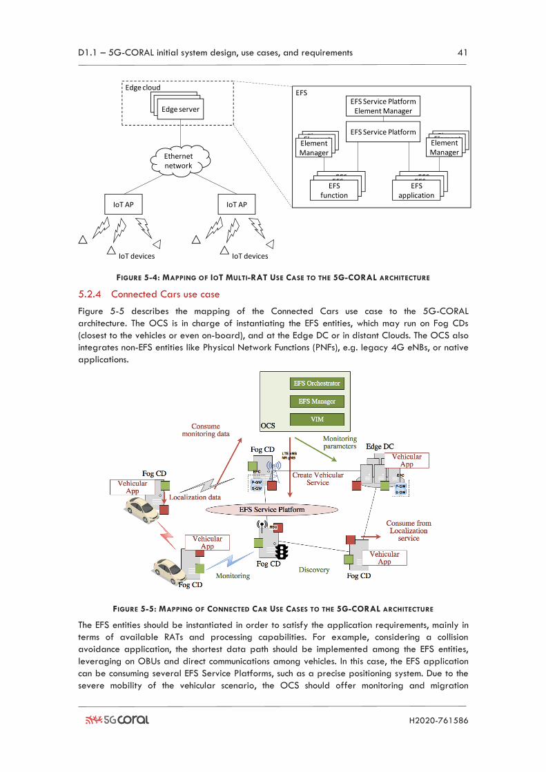
D1.1 – 5G-CORAL initial system design, use cases, and requirements 41
H2020-761586
FIGURE 5-4: MAPPING OF IOT MULTI-RAT USE CASE TO THE 5G-CORAL ARCHITECTURE
5.2.4 Connected Cars use case
Figure 5-5 describes the mapping of the Connected Cars use case to the 5G-CORAL
architecture. The OCS is in charge of instantiating the EFS entities, which may run on Fog CDs
(closest to the vehicles or even on-board), and at the Edge DC or in distant Clouds. The OCS also
integrates non-EFS entities like Physical Network Functions (PNFs), e.g. legacy 4G eNBs, or native
applications.
FIGURE 5-5: MAPPING OF CONNECTED CAR USE CASES TO THE 5G-CORAL ARCHITECTURE
The EFS entities should be instantiated in order to satisfy the application requirements, mainly in
terms of available RATs and processing capabilities. For example, considering a collision
avoidance application, the shortest data path should be implemented among the EFS entities,
leveraging on OBUs and direct communications among vehicles. In this case, the EFS application
can be consuming several EFS Service Platforms, such as a precise positioning system. Due to the
severe mobility of the vehicular scenario, the OCS should offer monitoring and migration
EFSEdge cloud
Edge server
IoT AP
Edge server
IoT devices
Edge server
IoT AP
IoT devices
Ethernetnetwork
EFS Service Platform
EFS functions
EFS functions
EFS function
EFS Service Platform Element Manager
ElementManager
ElementManager
ElementManager
EFS functions
EFS functions
EFS application
ElementManager
ElementManager
ElementManager
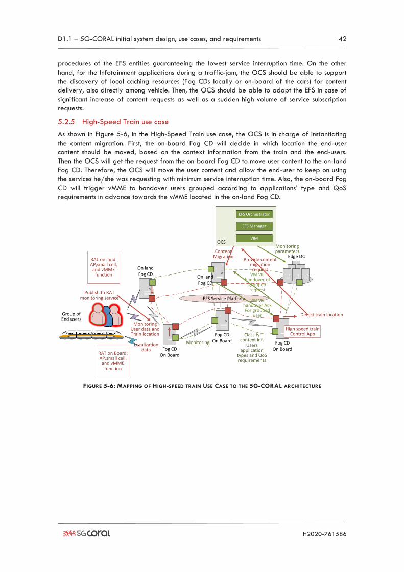
D1.1 – 5G-CORAL initial system design, use cases, and requirements 42
H2020-761586
procedures of the EFS entities guaranteeing the lowest service interruption time. On the other
hand, for the Infotainment applications during a traffic-jam, the OCS should be able to support
the discovery of local caching resources (Fog CDs locally or on-board of the cars) for content
delivery, also directly among vehicle. Then, the OCS should be able to adapt the EFS in case of
significant increase of content requests as well as a sudden high volume of service subscription
requests.
5.2.5 High-Speed Train use case
As shown in Figure 5-6, in the High-Speed Train use case, the OCS is in charge of instantiating
the content migration. First, the on-board Fog CD will decide in which location the end-user
content should be moved, based on the context information from the train and the end-users.
Then the OCS will get the request from the on-board Fog CD to move user content to the on-land
Fog CD. Therefore, the OCS will move the user content and allow the end-user to keep on using
the services he/she was requesting with minimum service interruption time. Also, the on-board Fog
CD will trigger vMME to handover users grouped according to applications’ type and QoS
requirements in advance towards the vMME located in the on-land Fog CD.
Fog CDOn Board
Edge DC
On land Fog CD
Fog CDOn Board
Fog CDOn Board
EFS Service PlatformPublish to RAT
monitoring service
Detect train location
High speed train Control App
OCS
EFS Manager
VIM
EFS Orchestrator
Classify context inf.
Users application
types and QoS requirements
Monitoring
Content Migration
Provide content migration request
Monitoring User data and Train location
Monitoring parameters
RAT on Board: AP,small cell,
and vMME function
Group of End users
Localization data
RAT on land: AP,small cell,
and vMME function On land
Fog CD
VMME handover of
grouped request
VMME handover AckFor grouped
user
FIGURE 5-6: MAPPING OF HIGH-SPEED TRAIN USE CASE TO THE 5G-CORAL ARCHITECTURE
D1.1 – 5G-CORAL initial system design, use cases, and requirements 43
H2020-761586
6 Conclusions After six months since its commencement, the 5G-CORAL project has reached a preliminary
system design as reported in this deliverable. This includes the definition of key use cases and an
initial list of the functional and non-functional requirements together with a baseline system
architecture, in addition to initial thoughts on the deployment of the use cases with the 5G-
CORAL system.
5G-CORAL considers the computing substrates in the continuum between Cloud and terminal
devices, which can be essentially classified into three tiers of Cloud, Edge, and Fog. Section 2 in
this deliverable has presented our analysis of computing substrates in these tiers. The computing
resources in different domains have been characterized. It is worth noting that, while Edge is
typically defined as a part of Fog, a special attention will be paid to mobile and volatile Fog
CDs (such as terminals) since they play a complementary role to static Edge DCs. As compared to
Cloud and Edge DCs that offer constant power supply and more capable computing, Fog CDs in
general are constrained due to form factor, battery and mobility. Some key attributes and
characteristics of computing substrates in these tiers have been surveyed.
In Section 3, three reference scenarios have been examined, namely Shopping Mall, Connected
Cars, and High-Speed Train. These three scenarios correspond to low, medium, and high user
mobility, respectively. In the scenario of Shopping Mall, the use cases including AR Navigation,
Cloud Robotics, and IoT Multi-RATs are considered. With the Connected Cars, we looked
particularly at the use cases of safety and infotainment during traffic-jam. Finally, High-Speed
Train use case focused on seamless connection and reduction of overhead required by frequent
handover.
As the initial design of the system, it is also crucial to first determine our expectation from 5G-
CORAL solution. Hence, Section 4 has identified initial set of functional and non-functional
technical requirements to consider for the design of the 5G-CORAL system. Commercial
requirements are not addressed in this deliverable but are planned in future work. Section 4 also
provided the KPIs and key innovations related to 5G-CORAL. The KPIs included business, societal,
and performance aspects. A mapping of the use cases to these KPIs and key innovations has also
been provided. Further work is anticipated here to define the performance targets and
measurement methodologies for the system performance metrics tailored to each use case.
Finally, the deliverable has presented a baseline functional architecture of 5G-CORAL solution,
wherein all the interfaces and entities within EFS and OCS are identified and expounded. It is
also shown the feasibility that such an architecture can be implemented and physically deployed
for different use cases.
As the first deliverable of WP1, the findings and plans presented are provided as key inputs to
ongoing developments in WP2, WP3, and WP4. The next deliverable from WP1 will expand on
the use cases, refine their requirements adding the business aspects, define the performance
metrics and measurement approaches, refine the architecture and expand on the deployment
options of 5G-CORAL solution for each use case.
D1.1 – 5G-CORAL initial system design, use cases, and requirements 44
H2020-761586
7 References [1] T. Taleb et al., "On Multi-Access Edge Computing: A Survey of the Emerging 5G Network Edge
Cloud Architecture and Orchestration", IEEE Communications Surveys & Tutorials, Vol. 19, No. 3,
Oct. 2017, pp.1657-1681
[2] H. E. Schaffer, "X as a Service, Cloud Computing, and the Need for Good Judgment," in IT
Professional, vol. 11, no. 5, pp. 4-5, Sept.-Oct. 2009
[3] “Multi-access Edge Computing.”, http://www.etsi.org/technologies-clusters/technologies/multi-
access-edge-computing
[4] F. Bonomi et al., “Fog computing and its role in the internet of things,” Proceedings of the first
edition of the MCC workshop on Mobile cloud computing - MCC ’12, pp. 13-16, 2012
[5] Some examples: https://cloud.google.com; https://azure.microsoft.com;
https://aws.amazon.com
[6] Peter Mell et al., The NIST Definition of Cloud Computing; NIST Special Publication 800-145;
September 2011
[7] https://www.supermicro.nl/products/nfo/MicroCloud.cfm
[8] https://www.pokemongo.com/
[9] https://techcrunch.com/2016/07/27/ar-in-mercedes-benzs-rescue-assist-app-gives-first-
responders-an-inside-look/
[10] https://www.engadget.com/2017/11/07/blippar-ar-city-navigation-app/
[11] B. Javidi,"Image Recognition and Classification: Algorithms, Systems, and Applications," New
York: Marcel Dekker Inc., 2002
[12] E. Kaplan et al., "Understanding GPS: Principles and Applications," Boston: Artech House, 2006
[13] N. Chang et al., "Robust indoor positioning using differential wi-fi access points," in IEEE
Transactions on Consumer Electronics, vol. 56, no. 3, pp. 1860-1867, Aug. 2010
[14] P. Zhang et al., “Cooperative localization in 5G networks: A survey,” ICT Express, 3(1), pp. 27-
32, 2017
[15] http://docs.cubieboard.org/tutorials/cc-a80/start
[16] B. Kehoe et al., "A Survey of Research on Cloud Robotics and Automation," in IEEE Transactions
on Automation Science and Engineering, vol. 12, no. 2, pp. 398-409, April 2015
[17] Ericsson Mobility Report, https://www.ericsson.com/en/mobility-report/internet-of-things-
forecast
[18] China Mobile Research Institute, June 2014, C-RAN White Paper: The Road Towards Green
Ran, http://labs.chinamobile.com/cran/
[19] Navid Nikaein et al., “Towards building Cloud-Native Radio Access Network using
OpenAirInterface,” Book Chapter of "Advances in Mobile Cloud Computing and Big Data in the
5G Era", Springer, 2016, {ISBN}: 978-3-319-45143-5,
http://www.eurecom.fr/en/publication/4843/detail/towards-a-cloud-native-radio-access-
network
[20] O. N. C. Yilmaz, “Ultra-Reliable and Low-Latency (urllc) 5G Communication,” EuCNC 2016,
http://kom.aau.dk/~nup/2016-06-27_Yilmaz-5G%20Ultra-reliable-Low-latency_final.pdf
[21] X. Hou et al., "Vehicular Fog Computing: A Viewpoint of Vehicles as the Infrastructures," in IEEE
Transactions on Vehicular Technology, vol. 65, no. 6, pp. 3860-3873, June 2016
[22] ETSI, "Mobile Edge Computing (MEC); Framework and Reference Architecture" GS MEC 003
V1.1.1 (2016-03), March, 2016
[23] E. Grigoreva et al., "Reducing mobility management signaling for automotive users in LTE
advanced," 2017 IEEE International Symposium on Local and Metropolitan Area Networks
(LANMAN), Osaka, 2017, pp. 1-6
[24] Nokia Siemens Networks, “Signaling Is Growing 50% Faster Than Data Traffic”, 2016 White
Paper