Embed Size (px)
Citation preview
There are 2 volt free relay contacts on the top PCB for connecting auxiliary equipment. These are programmable in the web browser set-up page.
MULTI BEAM ALIGNMENT & MASKINGThe multifunction lens fitted to D-TECT 3 IP produces seven long range beams and seven medium to short range curtain PIR beams. The PIR circuitry detects changes in heat and movement in the beam pattern; therefore items such as trees, shrubs, ponds, boiler flues, and animals should be considered when positioning the detector.
The detector is fitted with a mirror on the pyro sensor to provide a detection zone directly underneath the detector.
Note: The maximum mounting height is 3 metres when utilising the creep detection zone.
When using the pet immune configuration the mirror should be removed.
Note: The PIR sensor is more sensitive to movement across the beams, and less sensitive to movement directly towards or away from the beams.
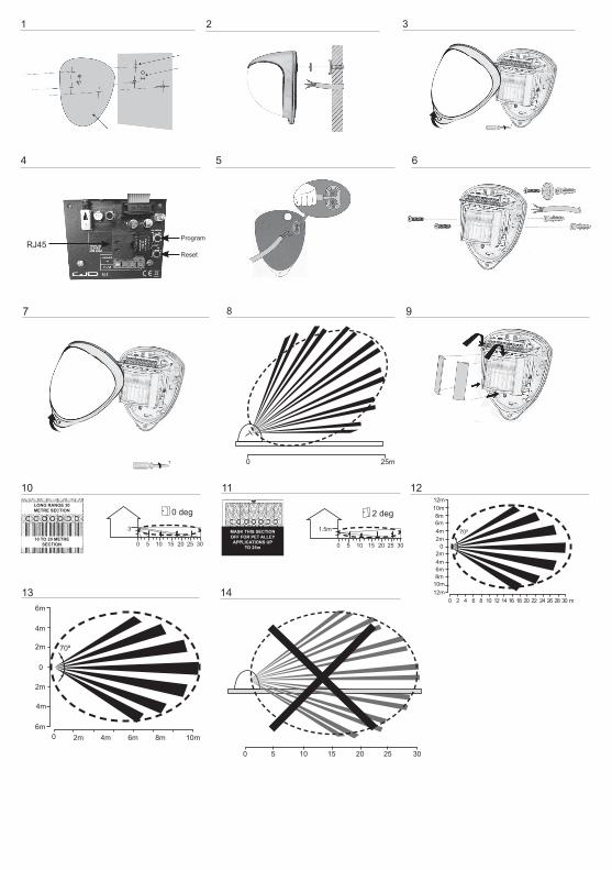
The detector module is fitted with two sliding shutters to reduce the detection angle. The curtains are fitted to the pan and tilt module as shown in Figure 9 (shown with primary and additional curtain sliders fitted). Each section of the detector lens gives a coverage pattern of approximately 10 degrees.
An additional set of curtain sliders is provided should the beam pattern need to be narrowed even further, e.g. if the minimum detection angle of 10 degrees is required.When coverage exceeds the desired detection area, adjust the module as required and mask off any beams, either vertically or horizontally, to avoid unwanted detection.Use portions of the self-adhesive silver mask applied to the rear, smooth side of the lens as shown in Figures 10 and 11. Always replace the lens the correct way up to ensure exact beam pattern coverage (top of the lens is marked TOP).
D-TECT 3 IPGJD260 IP Motion Detector
PACKAGE CONTENTS • 1 x D-TECT 3 IP• 1 x Drilling template for fixing holes• 3 x 31.75mm wall plugs• 3 x 31.75mm screws• 2 x Spare sliding curtains• 2 x Tamper feet• 1 x Tamper cup• 1 x Installation manual
INTRODUCTIONThe D-TECT 3 IP is a highly sophisticated, but user friendly, IP-based motion detection device and alarm trigger that harnesses the power of IP with PoE (Power over Ethernet) connectivity, advanced signal processing, quad pyro scanning and unique optical systems combined with microwave detection to provide state-of-the-art alarm capture.
MOUNTING THE UNITWARNING• NYLON WASHERS PROVIDED MUST BE USED
WITH SCREWS • ENSURE CABLE ENTRY AND SCREW HOLES ARE
SEALED WITH WATER BASED SEALANT• DO NOT USE SILICONE BASED SEALANT
During installation, protect the electronics against water, as trapped moisture can affect or damage the unit.
1. Drill the wall to accept the fixing screws, the cable entry, and the tamper cup (if used). See Figures 1 and 2. A hole-drilling template is provided. Note: GJD recommend using the tamper cup on uneven wall surfaces.
2. Remove the cover assembly by loosening the locking screw. The cover hinges from the top and lifts out of the location slot. See Figure 3.
3. Feed standard CAT5 cable into the cable entry. See Figures 2, 4 & 5.
4. Screw the unit to the wall ensuring that the rear tamper pin is correctly located and that the tamper micro switch is closed. See Figure 6. To aid installation, two spare tamper feet are provided. One is 1mm longer and the other is 2mm longer than the tamper foot originally fitted. The tamper foot is a push fit and can be removed by carefully pulling it from the pin. See Figure 2.
5. When the detector is aligned, connected, and programmed to suit the installation, replace the front cover and lock as shown. See Figure 7.
CONNECTING THE UNITFit the RJ45 plug to the cable and plug into the socket on the top PCB. This must be done before the cable is connected to the PoE switch.
When mounted at heights above 3 metres there could be a significant reduction in the range of detection and the target will have to move a greater distance within the field of view before an alarm is generated.
Figure 12 shows the pattern for the maximum range in the optimum position (see Figure 10). Masking the top section of the lens reduces the range to 20m.
Figure 13 shows the pattern for the minimum range. In this case masking the top section of the lens reduces the range to 6 meters.
Figures 14 and 8 illustrates alignment recommendations for when the detector is mounted close to a wall.
The alignment shown in Figure 14 is not recommended. If the detector module is orientated at an angle of 90° to the perimeter, the mounting wall may cut off short and medium range beams.
The long range beam will still detect an intruder, however the wall can cause false alarms when heated by sunlight.
Figure 8 shows the recommended alignment. The detector module is orientated at a 55° angle to the perimeter. As a result, short and medium range beams are parallel to the perimeter, but the detection range along the perimeter is reduced to 25 metres.
PROGRAMMINGThere are 2 different ways of programming the detection range, pulse count and LED setting.1. Using the programming button, programming LED and
programming chart below.2. Via the web based interface. The user can individually
program a number of configurable settings, as illustrated in the programming chart.
USING PROGRAMMING BUTTON
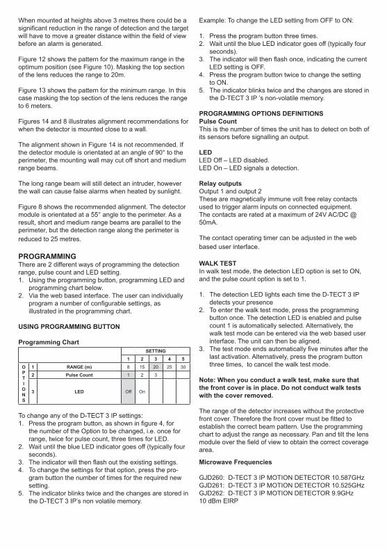
Programming ChartSETTING
1 2 3 4 5OPTION S
1 RANGE (m) 8 15 20 25 30
2 Pulse Count 1 2 3
3 LED Off On
To change any of the D-TECT 3 IP settings:1. Press the program button, as shown in figure 4, for
the number of the Option to be changed, i.e. once for range, twice for pulse count, three times for LED.
2. Wait until the blue LED indicator goes off (typically four seconds).
3. The indicator will then flash out the existing settings.4. To change the settings for that option, press the pro-
gram button the number of times for the required new setting.
5. The indicator blinks twice and the changes are stored in the D-TECT 3 IP’s non volatile memory.
Example: To change the LED setting from OFF to ON:
1. Press the program button three times.2. Wait until the blue LED indicator goes off (typically four
seconds).3. The indicator will then flash once, indicating the current
LED setting is OFF.4. Press the program button twice to change the setting
to ON.5. The indicator blinks twice and the changes are stored in
the D-TECT 3 IP ’s non-volatile memory.
PROGRAMMING OPTIONS DEFINITIONSPulse CountThis is the number of times the unit has to detect on both of its sensors before signalling an output.
LEDLED Off – LED disabled.LED On – LED signals a detection.
Relay outputsOutput 1 and output 2These are magnetically immune volt free relay contacts used to trigger alarm inputs on connected equipment.The contacts are rated at a maximum of 24V AC/DC @50mA.
The contact operating timer can be adjusted in the web based user interface.
WALK TESTIn walk test mode, the detection LED option is set to ON, and the pulse count option is set to 1.
1. The detection LED lights each time the D-TECT 3 IP detects your presence
2. To enter the walk test mode, press the programming button once. The detection LED is enabled and pulse count 1 is automatically selected. Alternatively, the walk test mode can be entered via the web based user interface. The unit can then be aligned.
3. The test mode ends automatically five minutes after the last activation. Alternatively, press the program button three times, to cancel the walk test mode.
Note: When you conduct a walk test, make sure that the front cover is in place. Do not conduct walk tests with the cover removed.
The range of the detector increases without the protective front cover. Therefore the front cover must be fitted to establish the correct beam pattern. Use the programming chart to adjust the range as necessary. Pan and tilt the lens module over the field of view to obtain the correct coverage area.
Microwave Frequencies
GJD260: D-TECT 3 IP MOTION DETECTOR 10.587GHzGJD261: D-TECT 3 IP MOTION DETECTOR 10.525GHzGJD262: D-TECT 3 IP MOTION DETECTOR 9.9GHz10 dBm EIRP
1 2 3
4 5 6
7 8 9
12
13 14
RJ45Program
Reset
0 25m
10LONG RANGE 30 METRE SECTION
10 TO 20 METRE SECTION
11
0 5 15
1.5m
2 deg
3010 2520
MASK THIS SECTION OFF FOR PET ALLEY APPLICATIONS UP
TO 25m
0 5 10 15 20 25 30
0 2 4 6 8 10 12 14 16 18 20 22 24 26 28 30 m
02m4m6m8m
10m12m
2m4m6m8m
10m12m
70º
70º
0 2m 4m 6m 8m 10m
2m
0
4m
6m
2m
4m
6m
0 5 15
3
0 deg
3010 2520
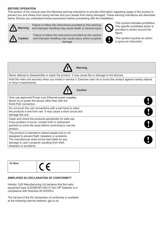
BEFORE OPERATIONThis section of the manual uses the following warning indications to provide information regarding usage of the product to prevent you and others from being harmed and your assets from being damaged. These warning indications are described below. Ensure you understand these precautions before proceeding with the installation.
Warning
Failure to follow the instructions provided by this warning and improper handling may cause death or serious injury
Caution
Failure to follow the instructions provided by this caution and improper handling may cause injury and/or property
damage
This symbol indicates prohibition. The specific prohibited action is provided in and/or around the figure.
This symbol requires an action or gives an instruction.
Warning
Never attempt to disassemble or repair the product. It may cause fire or damage to the devices.Hold the main unit securely when you install or service it. Exercise care not to bump the product against nearby objects or drop it inadvertently.
Caution
Only use approved Power over Ethernet power supplies.Never try to power the device other than with the RJ45 PoE connection.Do not touch the unit connections with a wet hand or when the products is wet from rain. It may cause a short circuit and damage the unit.Clean and check the products periodically for safe use. If any problem is found, contact GJD or authorised partners to solve the issue before continuing to use the product.This product is intended to detect people and is not designed to prevent theft, disasters or accidents. The manufacturer shall not be held liable for any damage to user’s property resulting from theft,disasters or accidents.
CE Mark
SIMPLIFIED EU DECLARATION OF CONFORMITY
Hereby, GJD Manufacturing Ltd declares that the radio equipment type GJD260/261/262 D-Tect 3IP Detector is in compliance with Directive 2014/53/EU.
The full text of the EU declaration of conformity is available at the following internet address: gjd.co.uk
PROGRAMMING - USING PROGRAMMING BUTTON
General connection 1. Connect the network cable and verify that the unit powers up and that the network connection is working.
Factory reset 1. Disconnect the network cable.2. Press and hold the reset button, while reconnecting the network cable.3. The unit will change IP address to the default IP and login.4. The unit will restart in the bootloader.
USER INTERFACESettings are made through the web based user interface. All that is needed is a modern web browser to access and change settings .
The instructions for the user interface described below are valid for firmware 1.32.
FACTORY DEFAULT SETTINGSWhen using the system for the first time, or if a factory reset has been made, the following settings are used:
Product IP number 192.168.0.10Subnet mask 255.255.255.0Default router 192.168.0.1
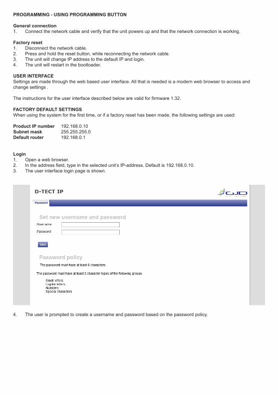
Login1. Open a web browser.2. In the address field, type in the selected unit’s IP-address. Default is 192.168.0.10.3. The user interface login page is shown.
4. The user is prompted to create a username and password based on the password policy.
INSTALLATION AND CONFIGURATION
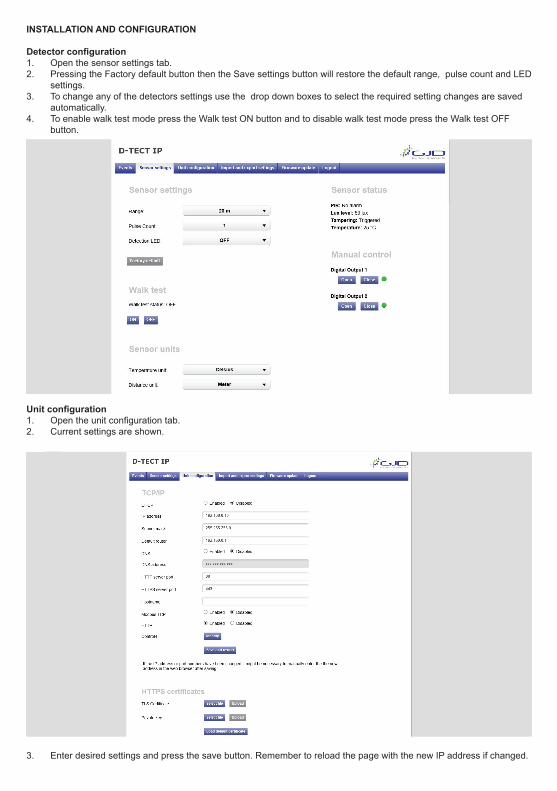
Detector configuration1. Open the sensor settings tab.2. Pressing the Factory default button then the Save settings button will restore the default range, pulse count and LED
settings.3. To change any of the detectors settings use the drop down boxes to select the required setting changes are saved
automatically.4. To enable walk test mode press the Walk test ON button and to disable walk test mode press the Walk test OFF
button.
Unit configuration1. Open the unit configuration tab. 2. Current settings are shown.
3. Enter desired settings and press the save button. Remember to reload the page with the new IP address if changed.
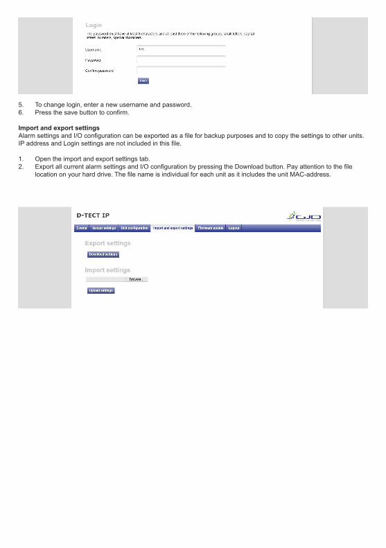
5. To change login, enter a new username and password. 6. Press the save button to confirm.
Import and export settingsAlarm settings and I/O configuration can be exported as a file for backup purposes and to copy the settings to other units. IP address and Login settings are not included in this file.
1. Open the import and export settings tab.2. Export all current alarm settings and I/O configuration by pressing the Download button. Pay attention to the file
location on your hard drive. The file name is individual for each unit as it includes the unit MAC-address.
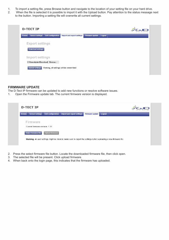
1. To import a setting file, press Browse button and navigate to the location of your setting file on your hard drive.2. When the file is selected it is possible to import it with the Upload button. Pay attention to the status message next
to the button. Importing a setting file will overwrite all current settings.
FIRMWARE UPDATEThe D-Tect IP firmware can be updated to add new functions or resolve software issues. 1. Open the Firmware update tab. The current firmware version is displayed.
2. Press the select firmware file button. Locate the downloaded firmware file, then click open. 3. The selected file will be present. Click upload firmware.4. When back onto the login page, this indicates that the firmware has uploaded.
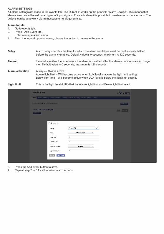
ALARM SETTINGSAll alarm settings are made in the events tab. The D-Tect IP works on the principle “Alarm - Action”. This means that alarms are created based on all types of input signals. For each alarm it is possible to create one or more actions. The actions can be a network alarm message or to trigger a relay.
Alarm inputs1. Go to events tab.2. Press “Add Event tab”.3. Enter a unique alarm name.4. From the Input dropdown menu, choose the action to generate the alarm.
Delay Alarm delay specifies the time for which the alarm conditions must be continuously fulfilled before the alarm is enabled. Default value is 0 seconds, maximum is 120 seconds.
Timeout Timeout specifies the time before the alarm is disabled after the alarm conditions are no longer met. Default value is 0 seconds, maximum is 120 seconds.
Alarm activation Always – Always active Above light limit – Will become active when LUX level is above the light limit setting. Below light limit – Will become active when LUX level is below the light limit setting.
Light limit This is the light level (LUX) that the Above light limit and Below light limit react.
6. Press the Add event button to save. 7. Repeat step 2 to 6 for all required alarm actions.
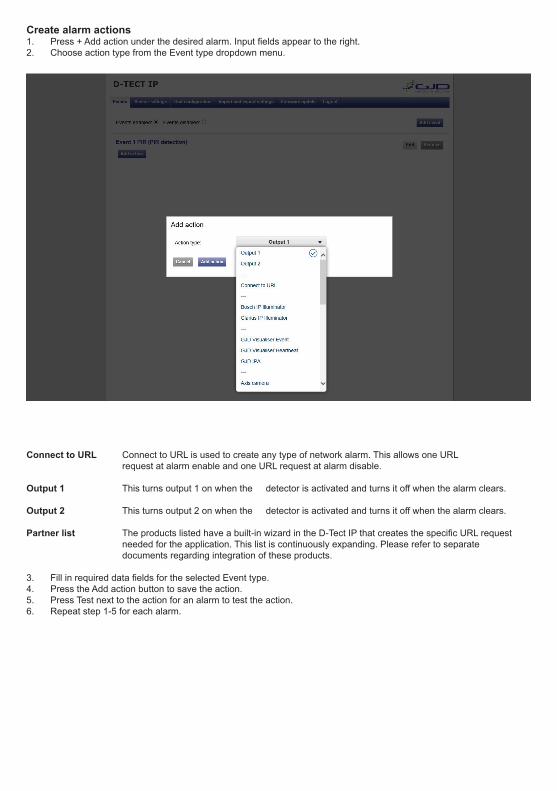
Create alarm actions1. Press + Add action under the desired alarm. Input fields appear to the right.2. Choose action type from the Event type dropdown menu.
Connect to URL Connect to URL is used to create any type of network alarm. This allows one URL request at alarm enable and one URL request at alarm disable.
Output 1 This turns output 1 on when the detector is activated and turns it off when the alarm clears. Output 2 This turns output 2 on when the detector is activated and turns it off when the alarm clears. Partner list The products listed have a built-in wizard in the D-Tect IP that creates the specific URL request needed for the application. This list is continuously expanding. Please refer to separate documents regarding integration of these products.
3. Fill in required data fields for the selected Event type.4. Press the Add action button to save the action.5. Press Test next to the action for an alarm to test the action.6. Repeat step 1-5 for each alarm.