Embed Size (px)
Citation preview
D-Su
b - W
D-Sub – W
06.01
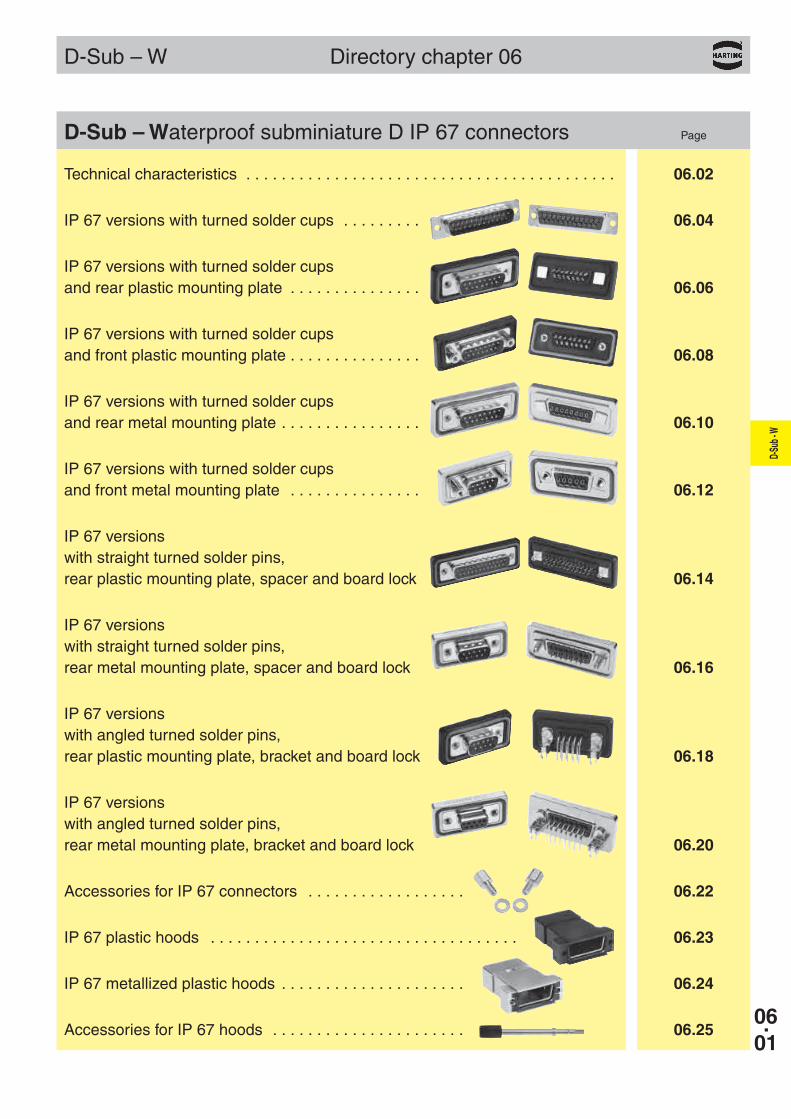
Technical characteristics . . . . . . . . . . . . . . . . . . . . . . . . . . . . . . . . . . . . . . . . . . 06.02
IP 67 versions with turned solder cups . . . . . . . . . 06.04
IP 67 versions with turned solder cups and rear plastic mounting plate . . . . . . . . . . . . . . . 06.06
IP 67 versions with turned solder cups and front plastic mounting plate . . . . . . . . . . . . . . . 06.08
IP 67 versions with turned solder cups and rear metal mounting plate . . . . . . . . . . . . . . . . 06.10
IP 67 versions with turned solder cups and front metal mounting plate . . . . . . . . . . . . . . . 06.12
IP 67 versions with straight turned solder pins, rear plastic mounting plate, spacer and board lock 06.14
IP 67 versions with straight turned solder pins, rear metal mounting plate, spacer and board lock 06.16
IP 67 versions with angled turned solder pins, rear plastic mounting plate, bracket and board lock 06.18
IP 67 versions with angled turned solder pins, rear metal mounting plate, bracket and board lock 06.20
Accessories for IP 67 connectors . . . . . . . . . . . . . . . . . . 06.22
IP 67 plastic hoods . . . . . . . . . . . . . . . . . . . . . . . . . . . . . . . . . . . 06.23
IP 67 metallized plastic hoods . . . . . . . . . . . . . . . . . . . . . 06.24
Accessories for IP 67 hoods . . . . . . . . . . . . . . . . . . . . . . 06.25
D-Sub – Waterproof subminiature D IP 67 connectors Page
Directory chapter 06
M FM F
M F
M F M F
06.02
D-Su
b - W
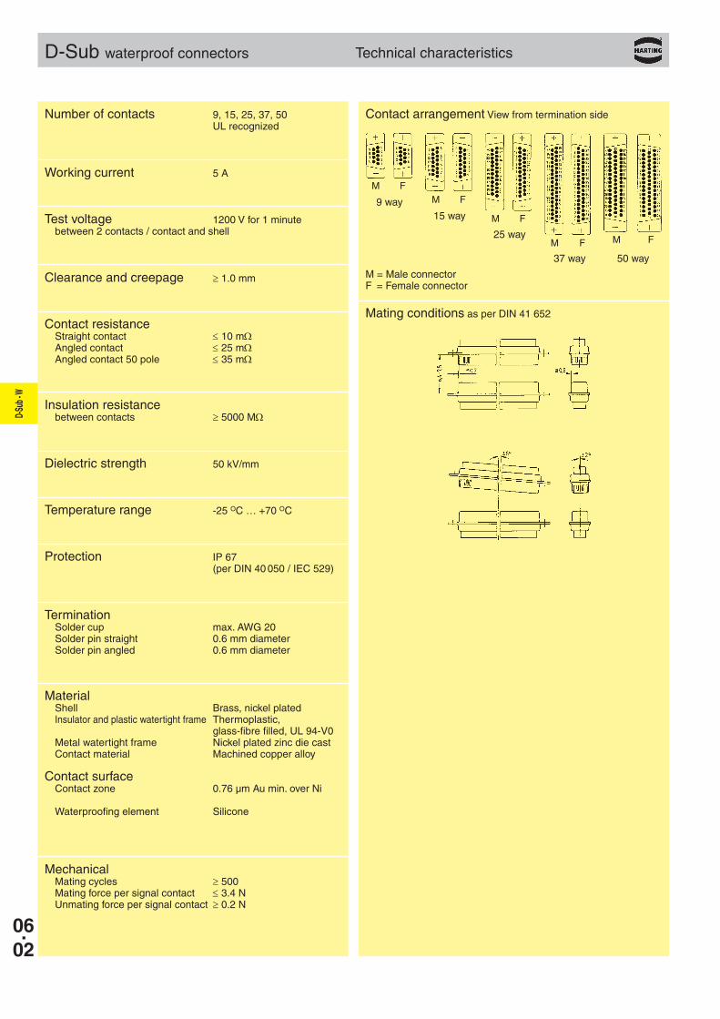
D-Sub waterproof connectors Technical characteristics
Contact arrangement View from termination side
Mating conditions as per DIN 41 652
M = Male connectorF = Female connector
37 way 50 way
Number of contacts 9, 15, 25, 37, 50 UL recognized
Working current 5 A
Test voltage 1200 V for 1 minute between 2 contacts / contact and shell
Clearance and creepage ≥ 1.0 mm
Contact resistance Straight contact ≤ 10 mΩ Angled contact ≤ 25 mΩ Angled contact 50 pole ≤ 35 mΩ
Insulation resistance between contacts ≥ 5000 MΩ
Dielectric strength 50 kV/mm
Temperature range -25 OC … +70 OC
Protection IP 67 (per DIN 40 050 / IEC 529)
Termination Solder cup max. AWG 20 Solder pin straight 0.6 mm diameter Solder pin angled 0.6 mm diameter
Material Shell Brass, nickel plated Insulator and plastic watertight frame Thermoplastic, glass-fibre filled, UL 94-V0 Metal watertight frame Nickel plated zinc die cast Contact material Machined copper alloy
Contact surface Contact zone 0.76 µm Au min. over Ni
Waterproofing element Silicone
Mechanical Mating cycles ≥ 500 Mating force per signal contact ≤ 3.4 N Unmating force per signal contact ≥ 0.2 N
9 way15 way
25 way
D-Su
b - W
06.03
Notes
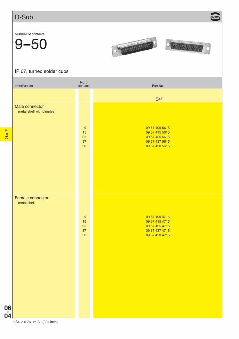
D-Sub
9 09 67 409 4715 15 09 67 415 4715 25 09 67 425 4715 37 09 67 437 4715 50 09 67 450 4715
9 09 67 409 5615 15 09 67 415 5615 25 09 67 425 5615 37 09 67 437 5615 50 09 67 450 5615
S41)
06.04
D-Su
b - W
1) S4: ≥ 0.76 µm Au (30 µinch)
Male connectormetal shell with dimples
Female connectormetal shell
No. ofIdentification contacts Part No.
IP 67, turned solder cups
Number of contacts
9--50
D-Su
b - W
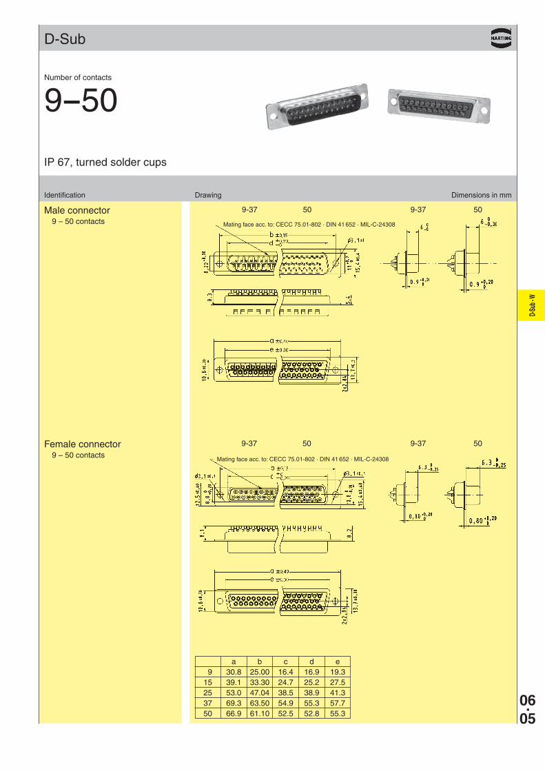
9-37 50 9-37 50
9-37 50 9-37 50
D-Sub
06.05
Identification Drawing Dimensions in mm
Male connector9 – 50 contacts
Female connector9 – 50 contacts
IP 67, turned solder cups
Number of contacts
9--50
Mating face acc. to: CECC 75.01-802 · DIN 41 652 · MIL-C-24308
Mating face acc. to: CECC 75.01-802 · DIN 41 652 · MIL-C-24308
a b c d e 9 30.8 25.00 16.4 16.9 19.3 15 39.1 33.30 24.7 25.2 27.5 25 53.0 47.04 38.5 38.9 41.3 37 69.3 63.50 54.9 55.3 57.7 50 66.9 61.10 52.5 52.8 55.3

06.06
D-Su
b - W
D-Sub
9 09 67 509 . 615 15 09 67 515 . 615 25 09 67 525 . 615
S41)
4-40 UNC þ 7 M3 þ 9
9 09 67 509 . 715 15 09 67 515 . 715 25 09 67 525 . 715
4-40 UNC þ 6 M3 þ 8
1) S4: ≥ 0.76 µm Au (30 µinch)
Male connectormetal shell with dimples
Female connectormetal shell
No. ofIdentification contacts Part No.
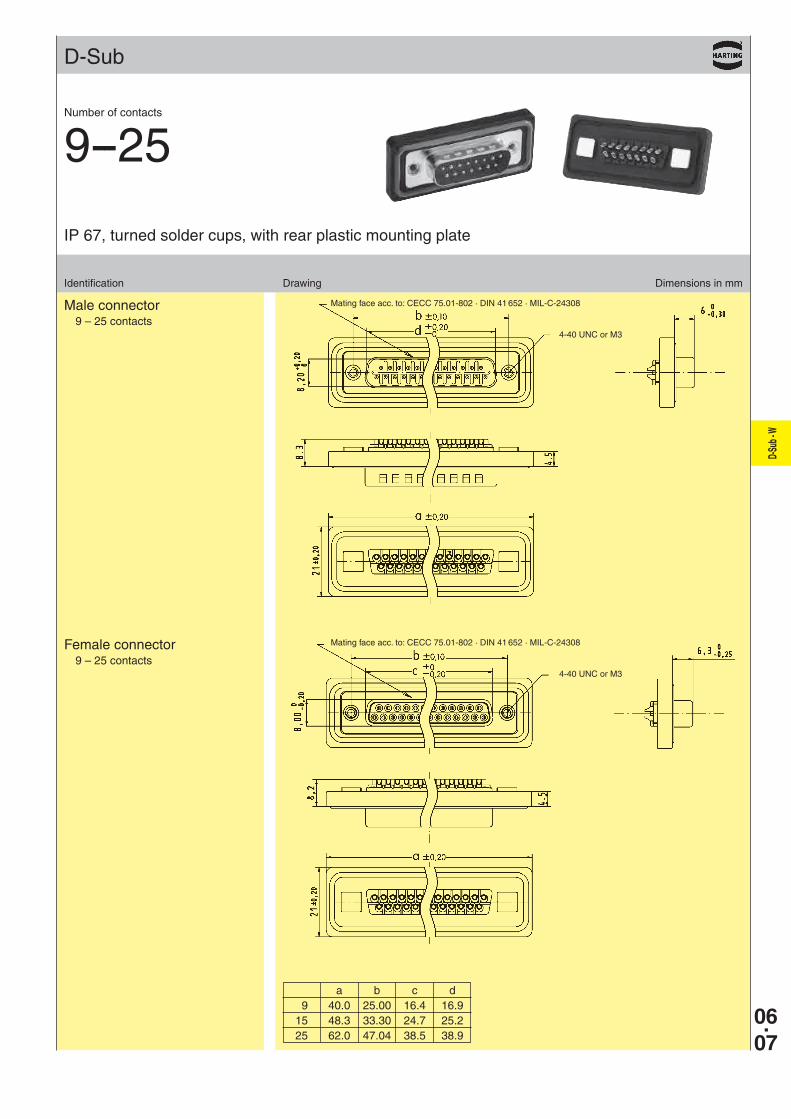
IP 67, turned solder cups, with rear plastic mounting plate
Number of contacts
9--25
Please insert digit for flange thread
Please insert digit for flange thread
D-Su
b - W
06.07
D-Sub
Identification Drawing Dimensions in mm
Male connector9 – 25 contacts
Female connector9 – 25 contacts
Mating face acc. to: CECC 75.01-802 · DIN 41 652 · MIL-C-24308
4-40 UNC or M3
4-40 UNC or M3
Mating face acc. to: CECC 75.01-802 · DIN 41 652 · MIL-C-24308
a b c d 9 40.0 25.00 16.4 16.9 15 48.3 33.30 24.7 25.2 25 62.0 47.04 38.5 38.9
IP 67, turned solder cups, with rear plastic mounting plate
Number of contacts
9--25
06.08
D-Su
b - W
D-Sub
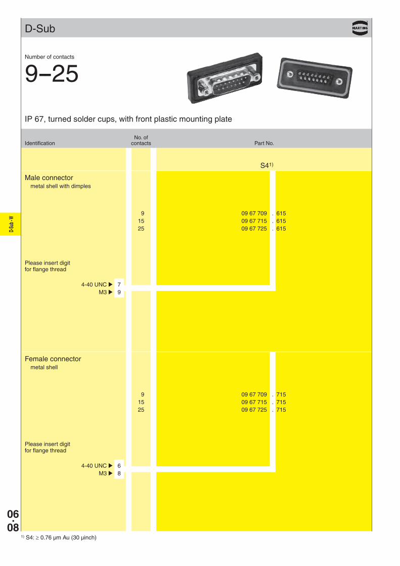
9 09 67 709 . 615 15 09 67 715 . 615 25 09 67 725 . 615
S41)
4-40 UNC þ 7 M3 þ 9
9 09 67 709 . 715 15 09 67 715 . 715 25 09 67 725 . 715
4-40 UNC þ 6 M3 þ 8
1) S4: ≥ 0.76 µm Au (30 µinch)
Male connectormetal shell with dimples
Female connectormetal shell
No. ofIdentification contacts Part No.
IP 67, turned solder cups, with front plastic mounting plate
Number of contacts
9--25
Please insert digit for flange thread
Please insert digit for flange thread
D-Su
b - W
06.09
D-Sub
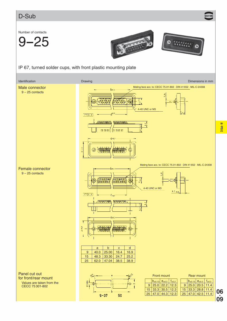
Identification Drawing Dimensions in mm
Male connector9 – 25 contacts
IP 67, turned solder cups, with front plastic mounting plate
Number of contacts
9--25
Female connector9 – 25 contacts
Mating face acc. to: CECC 75.01-802 · DIN 41 652 · MIL-C-24308
4-40 UNC or M3
4-40 UNC or M3
Mating face acc. to: CECC 75.01-802 · DIN 41 652 · MIL-C-24308
a b c d 9 40.0 25.00 16.4 16.9 15 48.3 33.30 24.7 25.2 25 62.0 47.04 38.5 38.9
b±0.13 e±0.2 f±0.2
9 25.0 20.5 11.4 15 33.3 28.8 11.4 25 47.0 42.5 11.4
b±0.13 e±0.2 f±0.2
9 25.0 22.2 12.3 15 33.3 30.5 12.3 25 47.0 44.3 12.3
Panel cut out for front/rear mount
Values are taken from the CECC 75 301-802
Front mount Rear mount
06.10
D-Su
b - W
D-Sub
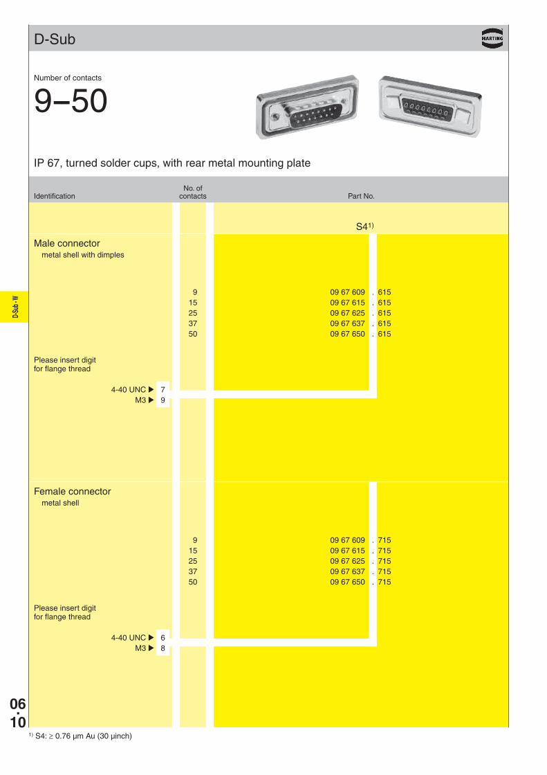
9 09 67 609 . 615 15 09 67 615 . 615 25 09 67 625 . 615 37 09 67 637 . 615 50 09 67 650 . 615
S41)
4-40 UNC þ 7 M3 þ 9
9 09 67 609 . 715 15 09 67 615 . 715 25 09 67 625 . 715 37 09 67 637 . 715 50 09 67 650 . 715
4-40 UNC þ 6 M3 þ 8
1) S4: ≥ 0.76 µm Au (30 µinch)
Male connectormetal shell with dimples
Female connectormetal shell
No. ofIdentification contacts Part No.
IP 67, turned solder cups, with rear metal mounting plate
Number of contacts
9--50
Please insert digit for flange thread
Please insert digit for flange thread
D-Su
b - W
06.11
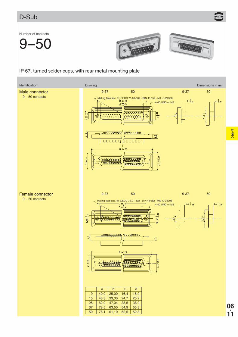
9-37 50 9-37 50
9-37 50 9-37 50
D-Sub
Identification Drawing Dimensions in mm
Male connector9 – 50 contacts
Female connector9 – 50 contacts
Mating face acc. to: CECC 75.01-802 · DIN 41 652 · MIL-C-24308
Mating face acc. to: CECC 75.01-802 · DIN 41 652 · MIL-C-24308
a b c d 9 40,0 25,00 16,4 16,9 15 48,3 33,30 24,7 25,2 25 62,0 47,04 38,5 38,9 37 78,5 63,50 54,9 55,3 50 76,1 61,10 52,5 52,8
4-40 UNC or M3
4-40 UNC or M3
IP 67, turned solder cups, with rear metal mounting plate
Number of contacts
9--50
06.12
D-Su
b - W
D-Sub
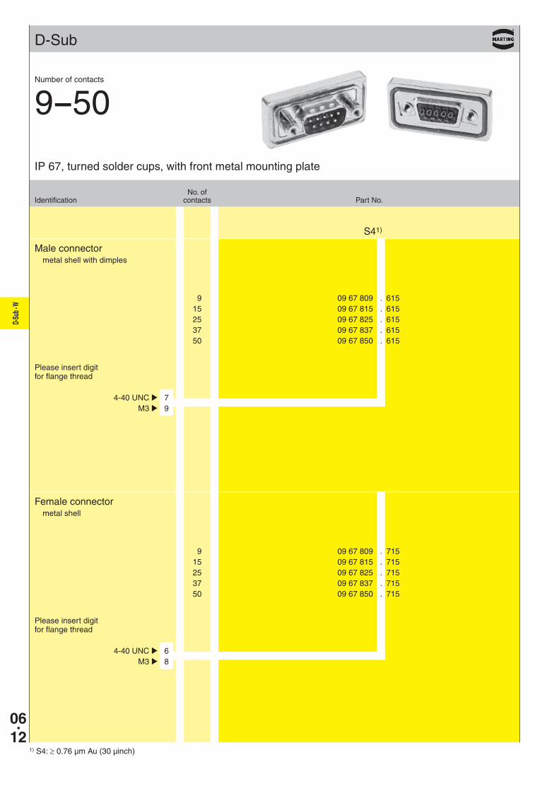
9 09 67 809 . 615 15 09 67 815 . 615 25 09 67 825 . 615 37 09 67 837 . 615 50 09 67 850 . 615
S41)
4-40 UNC þ 7 M3 þ 9
9 09 67 809 . 715 15 09 67 815 . 715 25 09 67 825 . 715 37 09 67 837 . 715 50 09 67 850 . 715
4-40 UNC þ 6 M3 þ 8
1) S4: ≥ 0.76 µm Au (30 µinch)
Male connectormetal shell with dimples
Female connectormetal shell
No. ofIdentification contacts Part No.
IP 67, turned solder cups, with front metal mounting plate
Number of contacts
9--50
Please insert digit for flange thread
Please insert digit for flange thread
D-Su
b - W
06.13
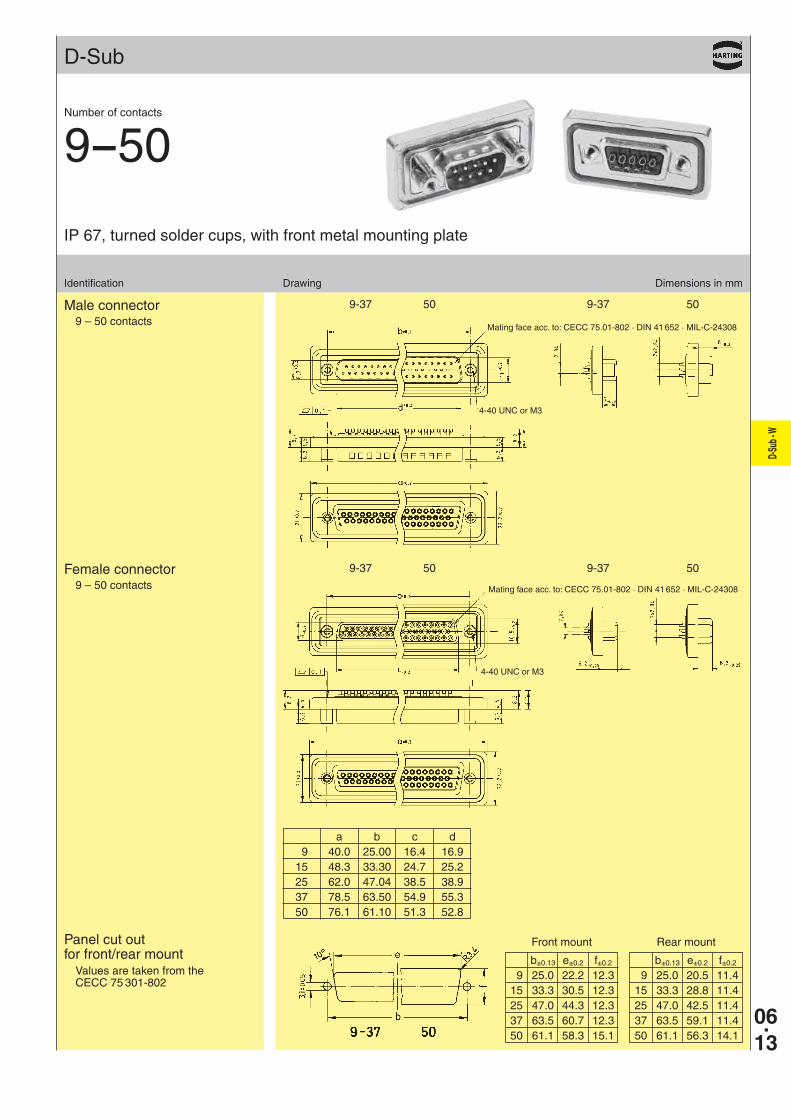
9-37 50 9-37 50
9-37 50 9-37 50
D-Sub
Identification Drawing Dimensions in mm
IP 67, turned solder cups, with front metal mounting plate
Number of contacts
9--50
Male connector9 – 50 contacts
Female connector9 – 50 contacts
Mating face acc. to: CECC 75.01-802 · DIN 41 652 · MIL-C-24308
Mating face acc. to: CECC 75.01-802 · DIN 41 652 · MIL-C-24308
a b c d 9 40.0 25.00 16.4 16.9 15 48.3 33.30 24.7 25.2 25 62.0 47.04 38.5 38.9 37 78.5 63.50 54.9 55.3 50 76.1 61.10 51.3 52.8
4-40 UNC or M3
4-40 UNC or M3
Panel cut out for front/rear mount
Values are taken from the CECC 75 301-802
b±0.13 e±0.2 f±0.2
9 25.0 20.5 11.4 15 33.3 28.8 11.4 25 47.0 42.5 11.4 37 63.5 59.1 11.4 50 61.1 56.3 14.1
b±0.13 e±0.2 f±0.2
9 25.0 22.2 12.3 15 33.3 30.5 12.3 25 47.0 44.3 12.3 37 63.5 60.7 12.3 50 61.1 58.3 15.1
Front mount Rear mount
06.14
D-Su
b - W
D-Sub
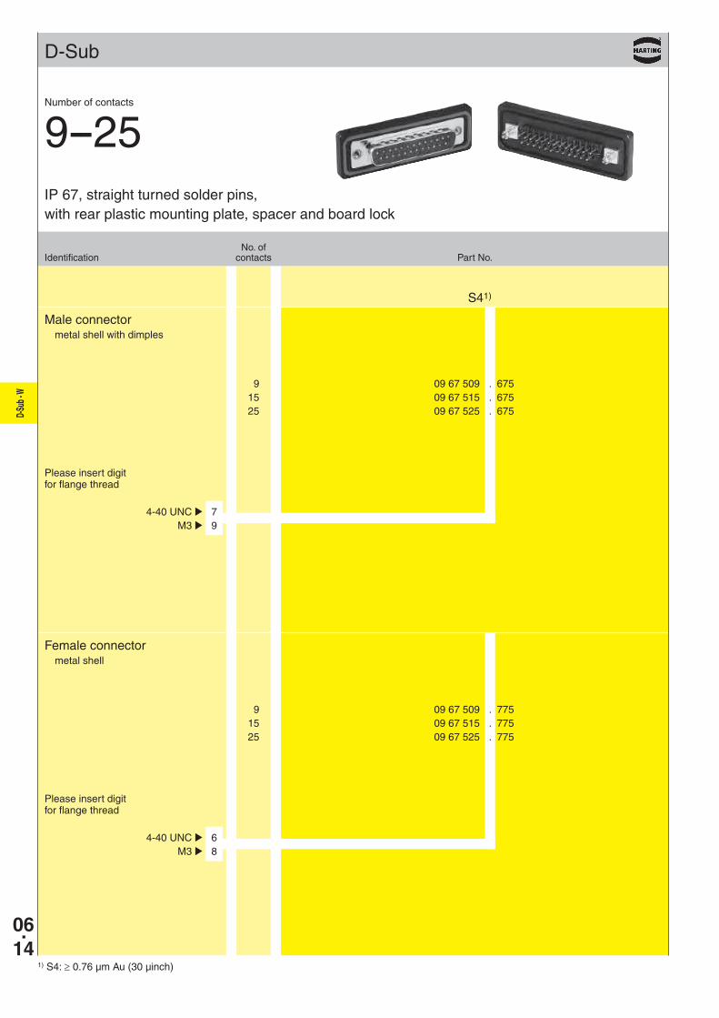
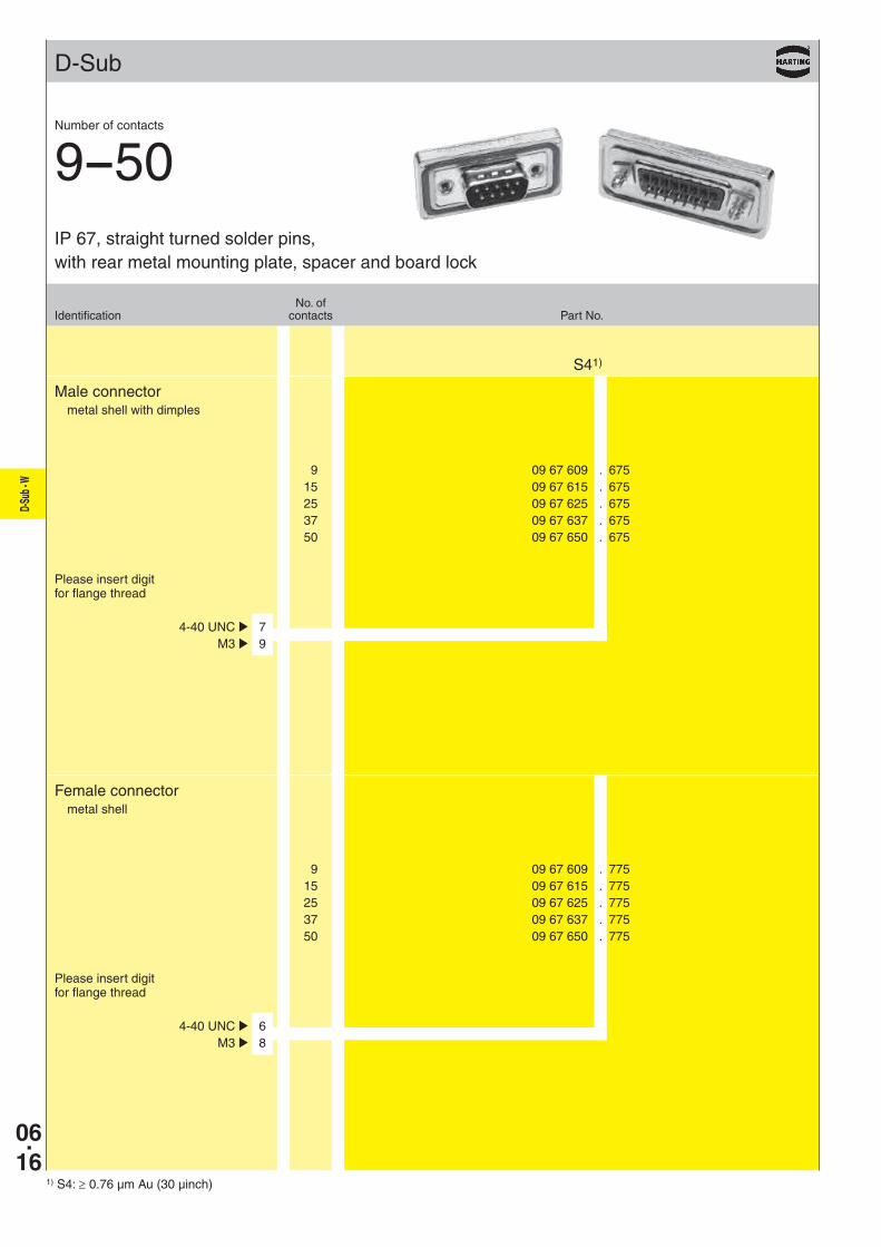
9 09 67 509 . 675 15 09 67 515 . 675 25 09 67 525 . 675
S41)
4-40 UNC þ 7 M3 þ 9
9 09 67 509 . 775 15 09 67 515 . 775 25 09 67 525 . 775
4-40 UNC þ 6 M3 þ 8
1) S4: ≥ 0.76 µm Au (30 µinch)
Male connectormetal shell with dimples
Female connectormetal shell
No. ofIdentification contacts Part No.
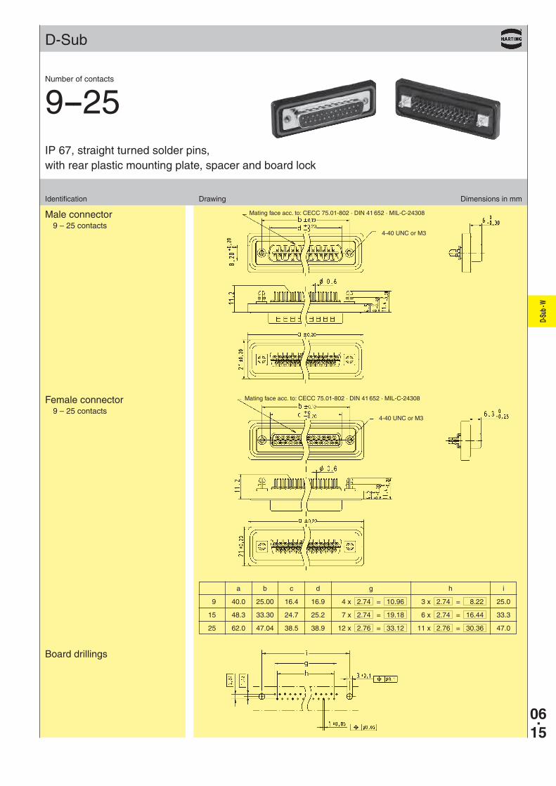
IP 67, straight turned solder pins, with rear plastic mounting plate, spacer and board lock
Number of contacts
9--25
Please insert digit for flange thread
Please insert digit for flange thread
D-Su
b - W
06.15
D-Sub
Identification Drawing Dimensions in mm
Male connector9 – 25 contacts
Female connector9 – 25 contacts
Board drillings
Mating face acc. to: CECC 75.01-802 · DIN 41 652 · MIL-C-24308
4-40 UNC or M3
4-40 UNC or M3
Mating face acc. to: CECC 75.01-802 · DIN 41 652 · MIL-C-24308
IP 67, straight turned solder pins, with rear plastic mounting plate, spacer and board lock
Number of contacts
9--25
a b c d g h i
9 40.0 25.00 16.4 16.9 4 x 2.74 = 10.96 3 x 2.74 = 8.22 25.0
15 48.3 33.30 24.7 25.2 7 x 2.74 = 19.18 6 x 2.74 = 16.44 33.3
25 62.0 47.04 38.5 38.9 12 x 2.76 = 33.12 11 x 2.76 = 30.36 47.0
06.16
D-Su
b - W
D-Sub
9 09 67 609 . 675 15 09 67 615 . 675 25 09 67 625 . 675 37 09 67 637 . 675 50 09 67 650 . 675
S41)
4-40 UNC þ 7 M3 þ 9
9 09 67 609 . 775 15 09 67 615 . 775 25 09 67 625 . 775 37 09 67 637 . 775 50 09 67 650 . 775
4-40 UNC þ 6 M3 þ 8
1) S4: ≥ 0.76 µm Au (30 µinch)
Male connectormetal shell with dimples
Female connectormetal shell
No. ofIdentification contacts Part No.
IP 67, straight turned solder pins, with rear metal mounting plate, spacer and board lock
Number of contacts
9--50
Please insert digit for flange thread
Please insert digit for flange thread
D-Su
b - W
06.17
D-Sub
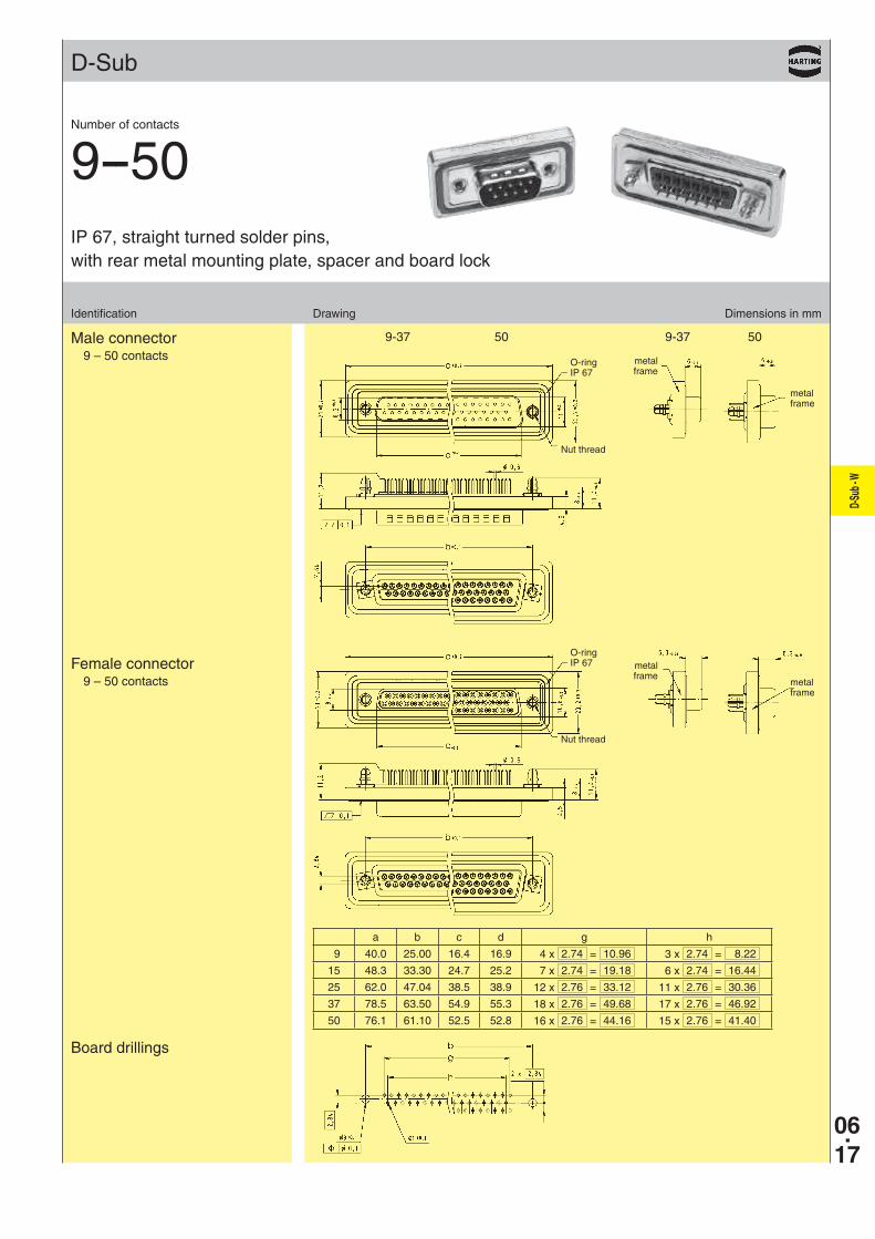
Identification Drawing Dimensions in mm
Male connector9 – 50 contacts
Female connector9 – 50 contacts
Board drillings
O-ringIP 67
a b c d g h
9 40.0 25.00 16.4 16.9 4 x 2.74 = 10.96 3 x 2.74 = 8.22
15 48.3 33.30 24.7 25.2 7 x 2.74 = 19.18 6 x 2.74 = 16.44
25 62.0 47.04 38.5 38.9 12 x 2.76 = 33.12 11 x 2.76 = 30.36
37 78.5 63.50 54.9 55.3 18 x 2.76 = 49.68 17 x 2.76 = 46.92
50 76.1 61.10 52.5 52.8 16 x 2.76 = 44.16 15 x 2.76 = 41.40
IP 67, straight turned solder pins, with rear metal mounting plate, spacer and board lock
Number of contacts
9--50
metalframe
metalframe
O-ringIP 67
metalframe
metalframe
Nut thread
Nut thread
9-37 50 9-37 50
06.18
D-Su
b - W
D-Sub
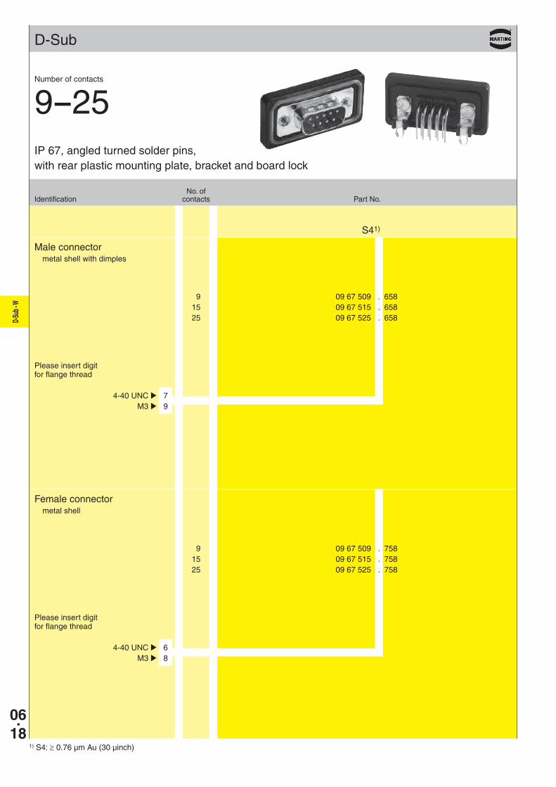
9 09 67 509 . 658 15 09 67 515 . 658 25 09 67 525 . 658
S41)
4-40 UNC þ 7 M3 þ 9
9 09 67 509 . 758 15 09 67 515 . 758 25 09 67 525 . 758
4-40 UNC þ 6 M3 þ 8
1) S4: ≥ 0.76 µm Au (30 µinch)
Male connectormetal shell with dimples
Female connectormetal shell
No. ofIdentification contacts Part No.
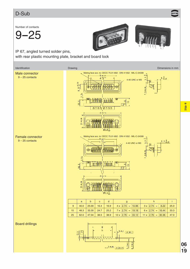
IP 67, angled turned solder pins, with rear plastic mounting plate, bracket and board lock
Number of contacts
9--25
Please insert digit for flange thread
Please insert digit for flange thread
D-Su
b - W
06.19
D-Sub
Identification Drawing Dimensions in mm
Male connector9 – 25 contacts
Female connector9 – 25 contacts
Board drillings
Mating face acc. to: CECC 75.01-802 · DIN 41 652 · MIL-C-24308
4-40 UNC or M3
4-40 UNC or M3
Mating face acc. to: CECC 75.01-802 · DIN 41 652 · MIL-C-24308
a b c d g h i
9 40.0 25.00 16.4 16.9 4 x 2.74 = 10.96 3 x 2.74 = 8.22 25.0
15 48.3 33.30 24.7 25.2 7 x 2.74 = 19.18 6 x 2.74 = 16.44 33.3
25 62.0 47.04 38.5 38.9 12 x 2.76 = 33.12 11 x 2.76 = 30.36 47.0
IP 67, angled turned solder pins, with rear plastic mounting plate, bracket and board lock
Number of contacts
9--25
06.20
D-Su
b - W
D-Sub
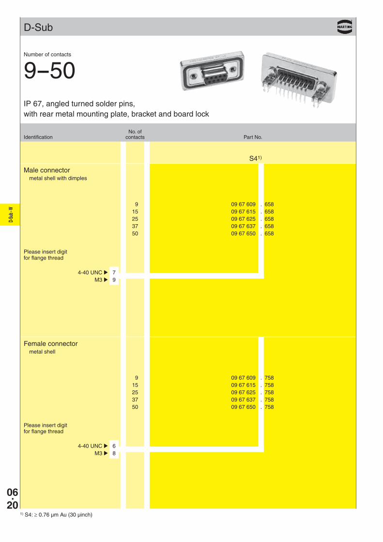
9 09 67 609 . 658 15 09 67 615 . 658 25 09 67 625 . 658 37 09 67 637 . 658 50 09 67 650 . 658
S41)
4-40 UNC þ 7 M3 þ 9
9 09 67 609 . 758 15 09 67 615 . 758 25 09 67 625 . 758 37 09 67 637 . 758 50 09 67 650 . 758
4-40 UNC þ 6 M3 þ 8
1) S4: ≥ 0.76 µm Au (30 µinch)
Male connectormetal shell with dimples
Female connectormetal shell
No. ofIdentification contacts Part No.
Number of contacts
9--50
Please insert digit for flange thread
Please insert digit for flange thread
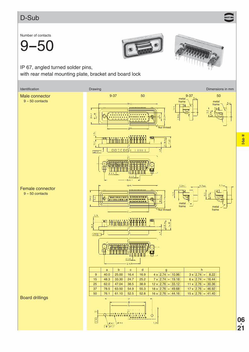
IP 67, angled turned solder pins, with rear metal mounting plate, bracket and board lock
D-Su
b - W
06.21
D-Sub
9-37 50 9-37 50
Identification Drawing Dimensions in mm
Male connector9 – 50 contacts
Female connector9 – 50 contacts
Board drillings
a b c d g h
9 40.0 25.00 16.4 16.9 4 x 2.74 = 10.96 3 x 2.74 = 8.22
15 48.3 33.30 24.7 25.2 7 x 2.74 = 19.18 6 x 2.74 = 16.44
25 62.0 47.04 38.5 38.9 12 x 2.76 = 33.12 11 x 2.76 = 30.36
37 78.5 63.50 54.9 55.3 18 x 2.76 = 49.68 17 x 2.76 = 46.92
50 76.1 61.10 52.5 52.8 16 x 2.76 = 44.16 15 x 2.76 = 41.40
metalframe
metalframe
Nut thread
Nut thread
Number of contacts
9--50IP 67, angled turned solder pins, with rear metal mounting plate, bracket and board lock
metalframe metal
frame
06.22
D-Su
b - W
D-Sub
9 09 67 002 9001 15 09 67 002 9002 25 09 67 002 9003 37 09 67 002 9004
50 09 67 002 9005
09 67 002 9006
09 67 002 9007
9 09 67 002 9055 15 09 67 002 9056 25 09 67 002 9057
9 09 67 002 9050 15 09 67 002 9051 25 09 67 002 9052
9 09 67 002 9065 15 09 67 002 9066 25 09 67 002 9067
9 09 67 002 9060 15 09 67 002 9061 25 09 67 002 9062
4-40 UNC
M3
4-40 UNC
M3
4-40 UNC
M3
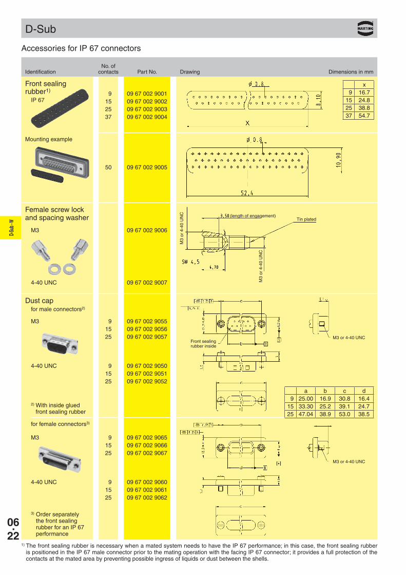
No. ofIdentification contacts Part No. Drawing Dimensions in mm
Accessories for IP 67 connectors
Front sealing rubber1)
IP 67
Female screw lockand spacing washer
x 9 16.715 24.825 38.837 54.7
Mounting example
(length of engagement)Tin plated
1) The front sealing rubber is necessary when a mated system needs to have the IP 67 performance; in this case, the front sealing rubber is positioned in the IP 67 male connector prior to the mating operation with the facing IP 67 connector; it provides a full protection of the contacts at the mated area by preventing possible ingress of liquids or dust between the shells.
Dust capfor male connectors2)
for female connectors3)
2) With inside glued front sealing rubber
3) Order separately the front sealing rubber for an IP 67 performance
Front sealing rubber inside
M3 or 4-40 UNC
M3 or 4-40 UNC
a b c d 9 25.00 16.9 30.8 16.415 33.30 25.2 39.1 24.725 47.04 38.9 53.0 38.5
M3
or 4
-40
UN
C
M3
or 4
-40
UN
C
D-Su
b - W
06.23
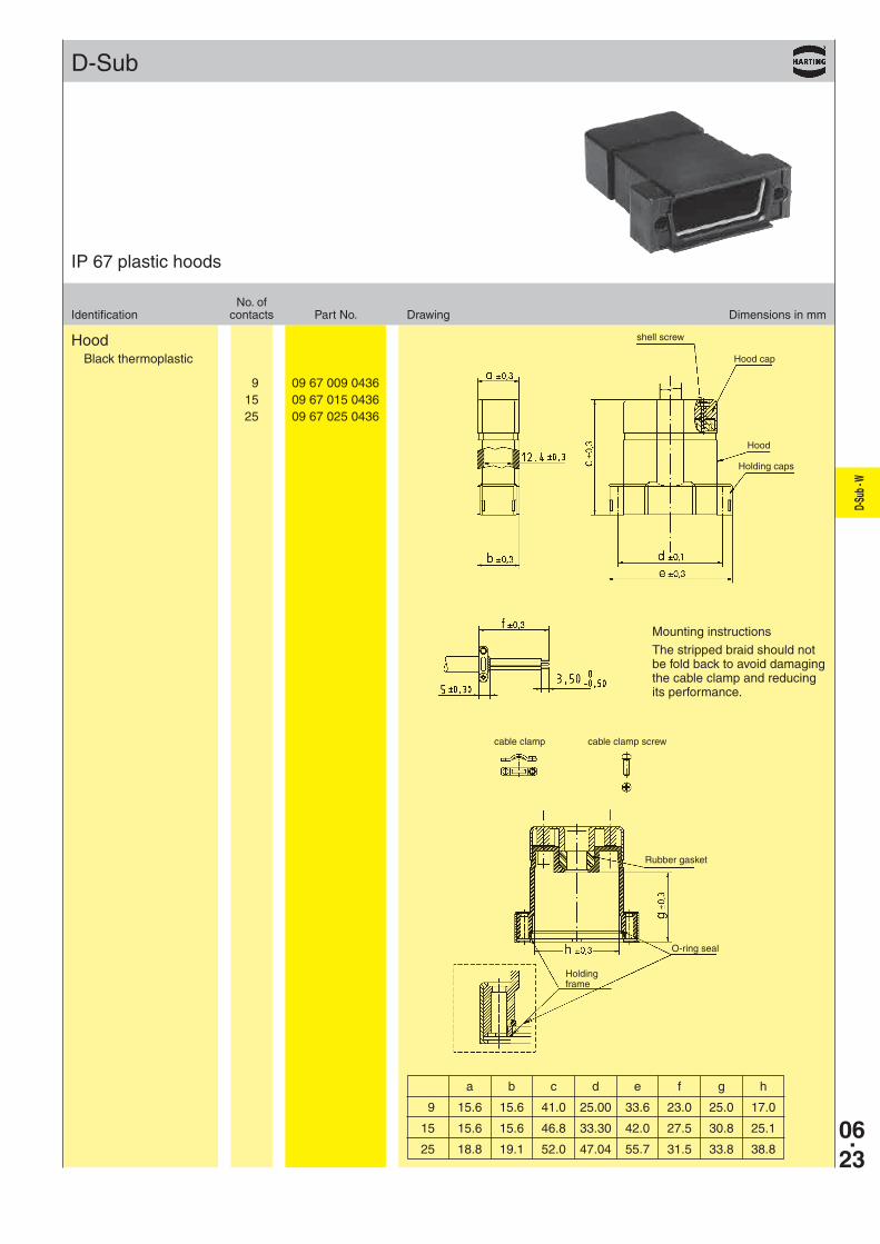
9 09 67 009 0436 15 09 67 015 0436 25 09 67 025 0436
D-Sub
No. ofIdentification contacts Part No. Drawing Dimensions in mm
IP 67 plastic hoods
HoodBlack thermoplastic
a b c d e f g h
9 15.6 15.6 41.0 25.00 33.6 23.0 25.0 17.0
15 15.6 15.6 46.8 33.30 42.0 27.5 30.8 25.1
25 18.8 19.1 52.0 47.04 55.7 31.5 33.8 38.8
shell screw
Hood cap
Hood
Holding caps
Rubber gasket
Mounting instructions
The stripped braid should not be fold back to avoid damaging the cable clamp and reducing its performance.
O-ring seal
Holding frame
cable clamp cable clamp screw
06.24
D-Su
b - W
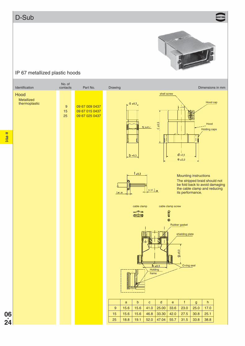
9 09 67 009 0437 15 09 67 015 0437 25 09 67 025 0437
D-Sub
No. ofIdentification contacts Part No. Drawing Dimensions in mm
IP 67 metallized plastic hoods
HoodMetallized thermoplastic
a b c d e f g h
9 15.6 15.6 41.0 25.00 33.6 23.0 25.0 17.0
15 15.6 15.6 46.8 33.30 42.0 27.5 30.8 25.1
25 18.8 19.1 52.0 47.04 55.7 31.5 33.8 38.8
shell screw
Hood cap
Hood
Holding caps
Rubber gasket
shielding plate
Mounting instructions
The stripped braid should not be fold back to avoid damaging the cable clamp and reducing its performance.
O-ring seal
Holding frame
cable clamp cable clamp screw
D-Su
b - W
06.25
D-Sub
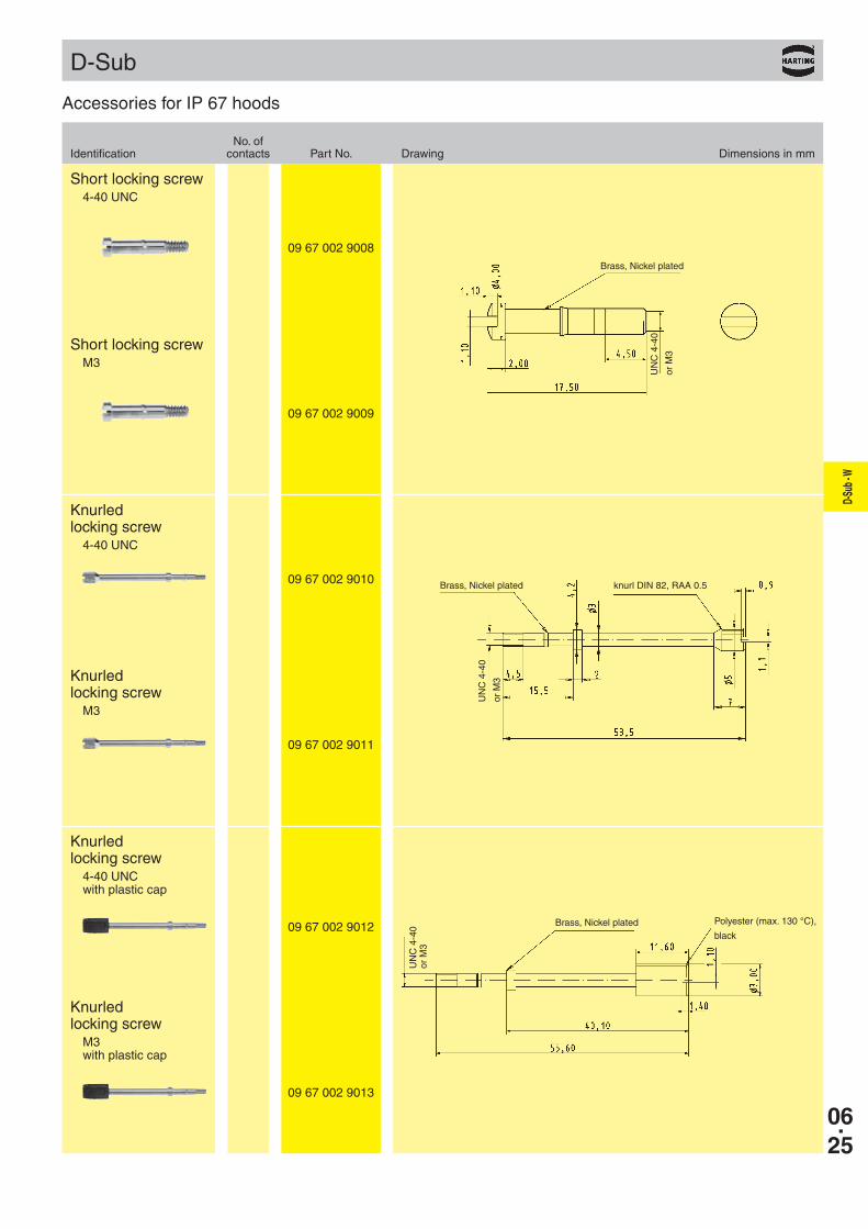
09 67 002 9009
09 67 002 9008
09 67 002 9011
09 67 002 9010
09 67 002 9013
09 67 002 9012
No. ofIdentification contacts Part No. Drawing Dimensions in mm
Accessories for IP 67 hoods
Short locking screwM3
Short locking screw4-40 UNC
Knurled locking screw
M3
Knurled locking screw
4-40 UNC
Knurled locking screw
M3 with plastic cap
Knurled locking screw
4-40 UNC with plastic cap
Brass, Nickel plated
UN
C 4
-40
or M
3
Brass, Nickel plated knurl DIN 82, RAA 0.5
UN
C 4
-40
or M
3
Brass, Nickel plated Polyester (max. 130 °C),
black
UN
C 4
-40
or M
3
06.26
D-Su
b - W
Notes