Embed Size (px)
Citation preview
53®
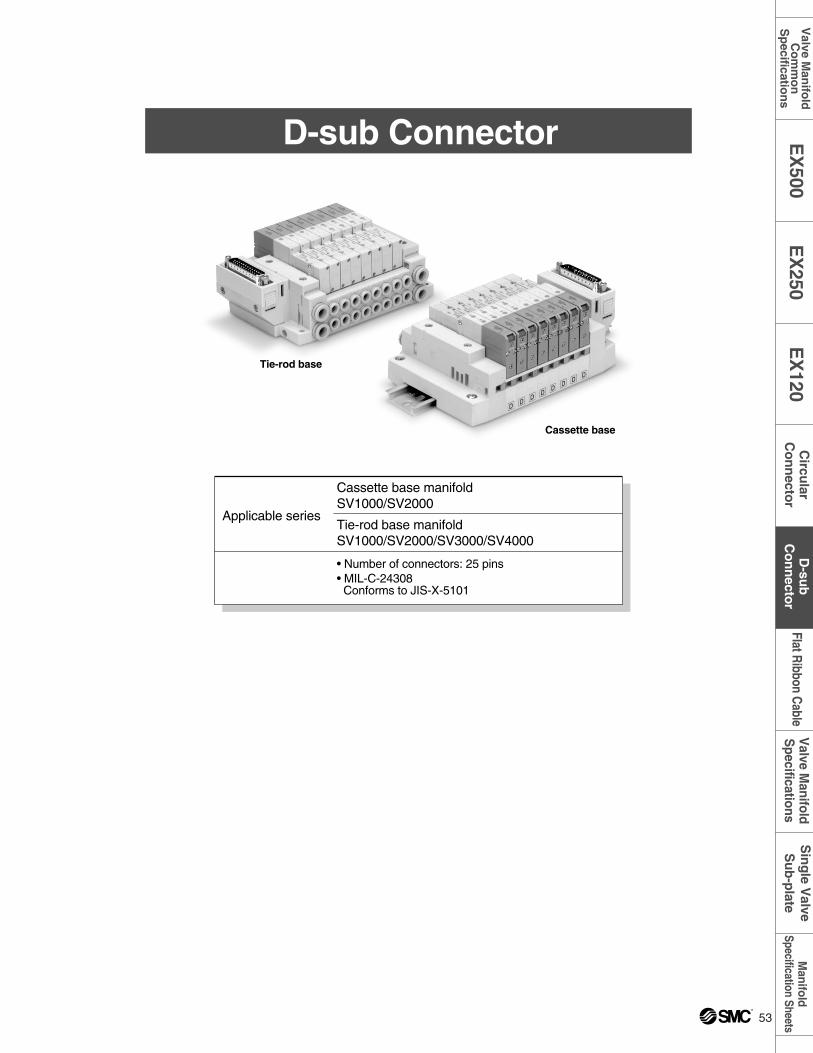
D-sub Connector
Applicable series
Cassette base manifoldSV1000/SV2000
Tie-rod base manifoldSV1000/SV2000/SV3000/SV4000
• Number of connectors: 25 pins• MIL-C-24308Conforms to JIS-X-5101
Tie-rod base
Cassette base
Manifold
Specification SheetsV
alve Manifold
Specifications
Flat Ribbon C
ableS
ing
le Valve
Su
b-p
lateD
-sub
Co
nn
ector
EX
250E
X120
Circu
larC
on
necto
rE
X500
Valve M
anifo
ldC
om
mo
nS
pecificatio
ns
54
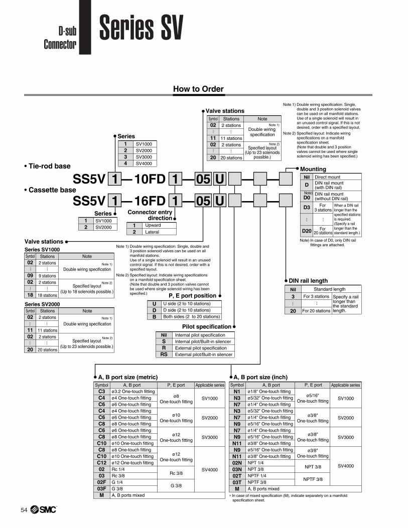
• Tie-rod base
• Cassette base
Series
SS5V –1 1
12
SV1000SV2000
SS5V – – – –0516FD1 1
Valve stations
DIN rail lengthStandard lengthNil
3
20
Note
Double wiring specification
Specified layout(Up to 23 solenoids
possible.)
Symbol02
1102
20
Stations2 stations
11 stations2 stations
20 stations
Connector entrydirection
12
Upward
Lateral
Series1234
SV1000SV2000SV3000SV4000
P, E port positionUDB
U side (2 to 10 stations)D side (2 to 10 stations)Both sides (2 to 20 stations)
......
......
For 3 stations
For 20 stations
... ...
MountingDirect mountDIN rail mount(with DIN rail)DIN rail mount(without DIN rail)
Nil
D
D0
D3
D20
For 3 stations
For 20 stations
... ...Pilot specification
Internal pilot specificationInternal pilot/Built-in silencerExternal pilot specificationExternal pilot/Built-in silencer
NilSR
RS
Note 1)
Note 2)
Valve stationsSeries SV1000
Series SV2000
Note
Double wiring specification
Specified layout(Up to 18 solenoids possible.)
Symbol02
0902
18
Stations2 stations
9 stations2 stations
18 stations
......
......
Note 1)
Note 2)
Note
Double wiring specification
Specified layout(Up to 23 solenoids possible.)
Symbol02
1102
20
Stations2 stations
11 stations2 stations
20 stations
......
......
Note 1)
Note 2)
– – –05 U10FD
UNote)
A, B port size (inch)Symbol
N1N3N7N3N7N9N7N9N11N9N1102N03N02T03TM
ø1/8" One-touch fittingø5/32" One-touch fittingø1/4" One-touch fittingø5/32" One-touch fittingø1/4" One-touch fittingø5/16" One-touch fittingø1/4" One-touch fittingø5/16" One-touch fittingø3/8" One-touch fittingø5/16" One-touch fittingø3/8" One-touch fittingNPT 1/4NPT 3/8NPTF 1/4NPTF 3/8A, B ports mixed
ø5/16"One-touch fitting
P, E port Applicable series
SV1000
SV2000
SV3000
SV4000
ø3/8"One-touch fitting
ø3/8"One-touch fitting
ø3/8"One-touch fitting
NPT 3/8
NPTF 3/8
A, B port size (metric)A, B port A, B portSymbol
C3C4C6C4C6C8C6C8C10C8C10C120203
02F03FM
ø3.2 One-touch fittingø4 One-touch fittingø6 One-touch fittingø4 One-touch fittingø6 One-touch fittingø8 One-touch fittingø6 One-touch fittingø8 One-touch fittingø10 One-touch fittingø8 One-touch fittingø10 One-touch fittingø12 One-touch fittingRc 1/4Rc 3/8G 1/4G 3/8A, B ports mixed
ø8One-touch fitting
P, E port Applicable series
SV1000
SV2000
SV3000
SV4000
ø10One-touch fitting
ø12One-touch fitting
ø12One-touch fitting
Rc 3/8
G 3/8
Note 1) Double wiring specification: Single, double and 3 position solenoid valves can be used on all manifold stations.Use of a single solenoid will result in an unused control signal. If this is not desired, order with a specified layout.
Note 2) Specified layout: Indicate wiring specifications on a manifold specification sheet. (Note that double and 3 position valves cannot be used where single solenoid wiring has been specified.)
When a DIN rail longer than the specified stations is required. (Specify a rail longer than the standard length.)
Note) In case of D0, only DIN rail fittings are attached.
Specify a rail longer than the standard length.
∗ In case of mixed specification (M), indicate separately on a manifold specification sheet.
Note 1) Double wiring specification: Single, double and 3 position solenoid valves can be used on all manifold stations.Use of a single solenoid will result in an unused control signal. If this is not desired, order with a specified layout.
Note 2) Specified layout: Indicate wiring specifications on a manifold specification sheet. (Note that double and 3 position valves cannot be used where single solenoid wiring has been specified.)
How to Order
D-subConnector
Series SV
54 ®
55®
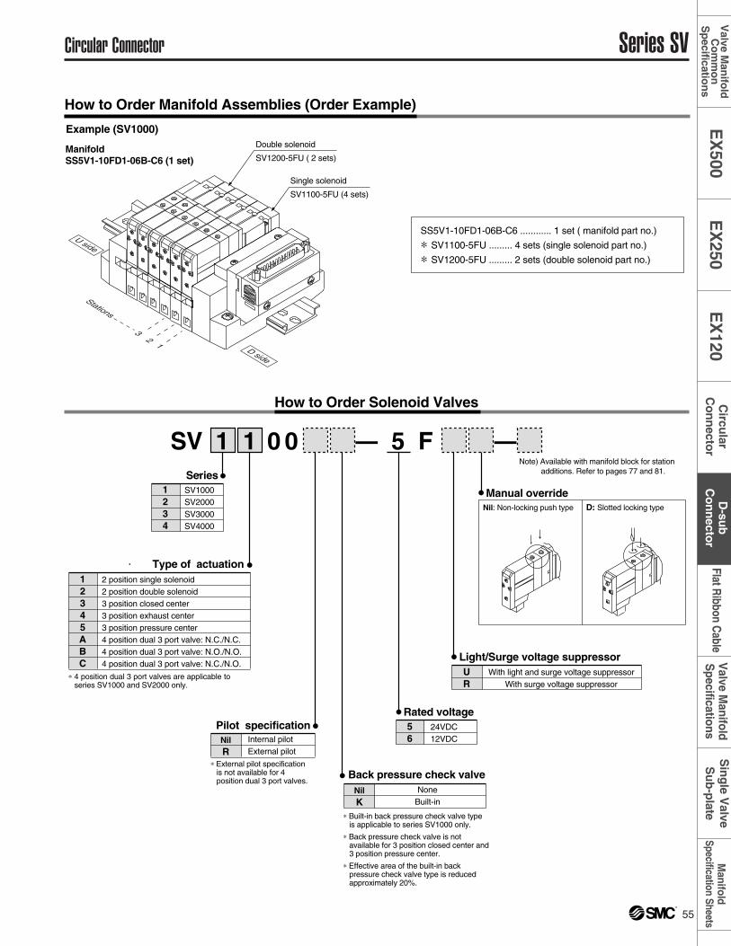
How to Order Manifold Assemblies (Order Example)
Example (SV1000)
Manual override
Rated voltage
Nil: Non-locking push type D: Slotted locking type
SV – –1 1 0 0 F5
56
24VDC12VDC
Note) Available with manifold block for station additions. Refer to pages 77 and 81.
Light/Surge voltage suppressorWith light and surge voltage suppressor
With surge voltage suppressorUR
Pilot specification
∗ External pilot specification is not available for 4 position dual 3 port valves.
∗ 4 position dual 3 port valves are applicable to series SV1000 and SV2000 only.
∗ Built-in back pressure check valve type is applicable to series SV1000 only.
∗ Back pressure check valve is not available for 3 position closed center and 3 position pressure center.
∗ Effective area of the built-in back pressure check valve type is reduced approximately 20%.
How to Order Solenoid Valves
Internal pilotExternal pilot
NilR
Back pressure check valveNone
Built-inNilK
Series1234
SV1000SV2000SV3000SV4000
Type of actuation12345ABC
2 position single solenoid2 position double solenoid3 position closed center3 position exhaust center3 position pressure center4 position dual 3 port valve: N.C./N.C.4 position dual 3 port valve: N.O./N.O.4 position dual 3 port valve: N.C./N.O.
Double solenoid
SV1200-5FU ( 2 sets)
Single solenoid
SV1100-5FU (4 sets)
32
1
Stations
U side
D side
SS5V1-10FD1-06B-C6 ............ 1 set ( manifold part no.)
∗ SV1100-5FU ......... 4 sets (single solenoid part no.)
∗ SV1200-5FU ......... 2 sets (double solenoid part no.)
ManifoldSS5V1-10FD1-06B-C6 (1 set)
DD
DD
DD
Circular Connector Series SVM
anifoldSpecification Sheets
Valve M
anifoldS
pecificationsFlat R
ibbon Cable
Sin
gle V
alveS
ub
-plate
D-su
bC
on
necto
rE
X250
EX
120C
ircular
Co
nn
ector
EX
500V
alve Man
ifold
Co
mm
on
Sp
ecification
s
56 ®
Series SV D-sub Connector
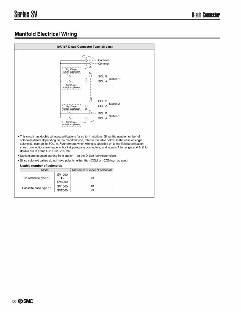
10F/16F D-sub Connector Type (25 pins)
Model Maximum number of solenoids
Tie-rod base type 10SV1000
toSV4000
23
1823
SV1000SV2000
Cassette base type 16
Manifold Electrical Wiring
Usable number of solenoids
Light/Surgevoltage suppressor
Light/Surgevoltage suppressor
Light/Surgevoltage suppressor
Light/Surgevoltage suppressor
CommonCommon
SOL. B
SOL. A
SOL. B
SOL. A
SOL. BStation 1
Station 2
Station 1
SOL. A
13
12
11
2
1
25
24
15
14
• This circuit has double wiring specifications for up to 11 stations. Since the usable number of solenoids differs depending on the manifold type, refer to the table below. In the case of single solenoids, connect to SOL. A. Furthermore, when wiring is specified on a manifold specification sheet, connections are made without skipping any connectors, and signals A for single and A, B for double are in order 1→14→2→15, etc.
• Stations are counted starting from station 1 on the D side (connector side).
• Since solenoid valves do not have polarity, either the +COM or –COM can be used.
57®
Dimensions: Series SV1000 for D-sub Connector
Circular Connector Series SV
( )
UDB
12
C3, N1C4, N3C6, N7
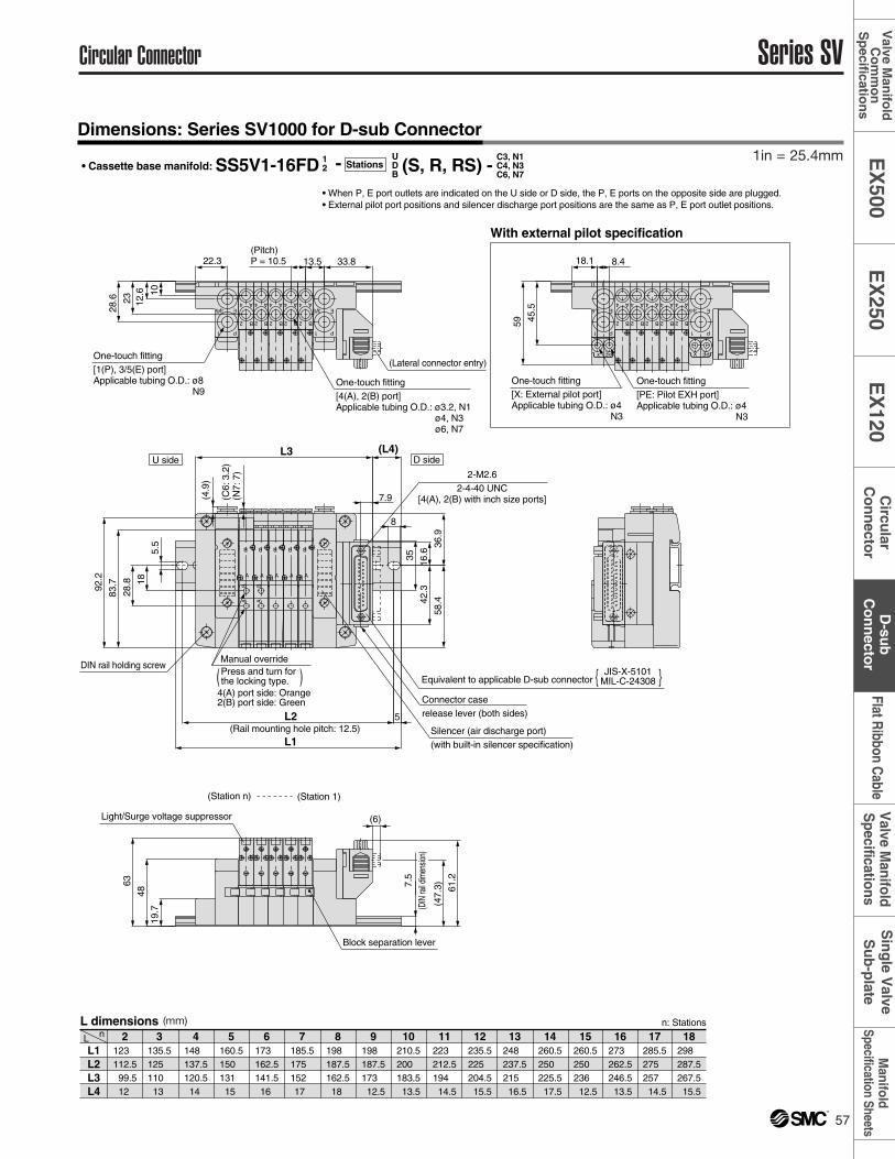
• Cassette base manifold: SS5V1-16FD (S, R, RS) -- Stations
• When P, E port outlets are indicated on the U side or D side, the P, E ports on the opposite side are plugged. • External pilot port positions and silencer discharge port positions are the same as P, E port outlet positions.
L1L2L3L4
L n 2123 112.5 99.512
5160.5150 131 15
6173 162.5141.516
7185.5175 152 17
8198 187.5162.518
9198 187.5173 12.5
10210.5200 183.5 13.5
11223 212.5194 14.5
12235.5225 204.5 15.5
13248 237.5215 16.5
14260.5250 225.5 17.5
15260.5250 236 12.5
16273 262.5246.5 13.5
17285.5275 257 14.5
18298 287.5267.5 15.5
4148 137.5120.514
3135.5125 110 13
L dimensions n: Stations
(Pitch)P = 10.5
(Rail mounting hole pitch: 12.5)
(Lateral connector entry)
DIN rail holding screw
(Station n) (Station 1)
One-touch fitting[1(P), 3/5(E) port]Applicable tubing O.D.: ø8
N9One-touch fitting[4(A), 2(B) port]Applicable tubing O.D.: ø3.2, N1
ø4, N3ø6, N7
JIS-X-5101MIL-C-24308Equivalent to applicable D-sub connector { }
U side D side
P1
5 3 E
P1
5 3 E
B
A
2
4
B
A
2
4
B
A
2
4
B
A
2
4
B
A
2
4
One-touch fitting[X: External pilot port]Applicable tubing O.D.: ø4
N3
One-touch fitting[PE: Pilot EXH port]Applicable tubing O.D.: ø4
N3
Connector caserelease lever (both sides)
2-M2.62-4-40 UNC
[4(A), 2(B) with inch size ports]
Light/Surge voltage suppressor
Block separation lever
With external pilot specification
B
A
2
4
B
A
2
4
B
A
2
4
B
A
2
4
B
A
2
4
A
B
A
B
A
B
A
B
AB
A
B
AB
P1
5 3 E
P1
5 3 E
PE
x
PE
X
(4.9
)
28.8
(C6:
3.2
)(N
7: 7
)
83.792
.2 1819
.748
10
2363
12.6
28.6
13.5
35
42.3
16.6
36.9
58.4
8
L3 (L4)
L2 5
L1
5.5
22.3 33.8
61.2
45.5
59
18.1 8.4
(47.
3)
(6)
Manual overridePress and turn forthe locking type.
Silencer (air discharge port)(with built-in silencer specification)
4(A) port side: Orange2(B) port side: Green
7.5
(DIN
rail d
imen
sion)
7.9
Manifold
Specification SheetsV
alve Manifold
Specifications
Flat Ribbon C
ableS
ing
le Valve
Su
b-p
lateD
-sub
Co
nn
ector
EX
250E
X120
Circu
larC
on
necto
rE
X500
Valve M
anifo
ldC
om
mo
nS
pecificatio
ns
1in = 25.4mm
(mm)
58 ®
Series SV D-sub Connector
Dimensions: Series SV2000 for D-sub Connector
( )
UDB
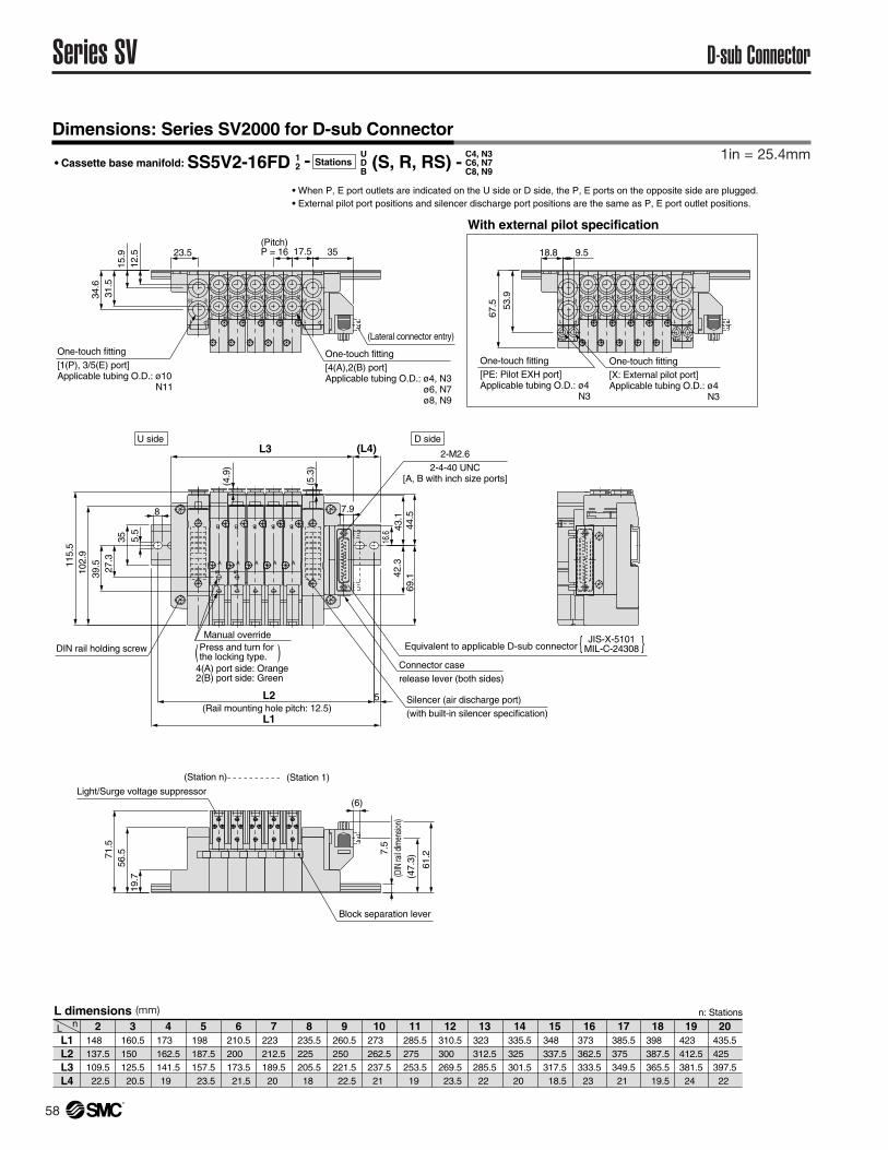
12• Cassette base manifold: SS5V2-16FD - Stations (S, R, RS) -
L1L2L3L4
L n 2148 137.5109.5 22.5
5198 187.5157.5 23.5
6210.5200 173.5 21.5
7223 212.5189.520
8235.5225 205.518
9260.5250 221.5 22.5
10273 262.5237.521
11285.5275 253.519
12310.5300 269.5 23.5
13323 312.5285.522
14335.5325 301.520
15348 337.5317.5 18.5
16373 362.5333.523
17385.5375 349.521
18398 387.5365.5 19.5
19423 412.5381.524
20435.5425 397.522
4173 162.5141.519
3160.5150 125.5 20.5
L dimensions n: Stations
• When P, E port outlets are indicated on the U side or D side, the P, E ports on the opposite side are plugged. • External pilot port positions and silencer discharge port positions are the same as P, E port outlet positions.
C4, N3C6, N7C8, N9
Manual overridePress and turn forthe locking type.
Silencer (air discharge port)(with built-in silencer specification)
4(A) port side: Orange2(B) port side: Green
(Station n) (Station 1)
(Rail mounting hole pitch: 12.5)
One-touch fitting[1(P), 3/5(E) port]Applicable tubing O.D.: ø10
N11
One-touch fitting[4(A),2(B) port]Applicable tubing O.D.: ø4, N3
ø6, N7ø8, N9
(Pitch)P = 16
DIN rail holding screw
With external pilot specification
U side D side
JIS-X-5101
MIL-C-24308Equivalent to applicable D-sub connector { }
(Lateral connector entry)
One-touch fitting[PE: Pilot EXH port]Applicable tubing O.D.: ø4
N3
One-touch fitting[X: External pilot port]Applicable tubing O.D.: ø4
N3
Connector caserelease lever (both sides)
2-M2.62-4-40 UNC
[A, B with inch size ports]
Light/Surge voltage suppressor
Block separation lever
P1
E3/5
P1
E3/5
P1
E3/5
P1
E3/5
PE
x
PE
X
A
B
A
B
A
B
AB
A
B
AB
A
B
B
A
2
4
B
A
2
4
B
A
2
4
B
A
2
4
B
A
2
4
B
A
2
4
B
A
2
4
B
A
2
4
B
A
2
4
B
A
2
4
19.7
56.571
.527
.339
.510
2.9
115.
5
43.1
69.1
23.5
12.5
15.9
31.5
34.6
17.5
61.2
L2
L1
5
5.5
35
8
L3 (L4)
42.3
16.6
35
53.9
67.5
7.9
(5.3
)
18.8 9.5
(47.
3)
(6)
(4.9
)
44.5
7.5
(DIN
rail d
imen
sion)
1in = 25.4mm
(mm)
59®
( )
UDB
12
C3, N1C4, N3C6, N7
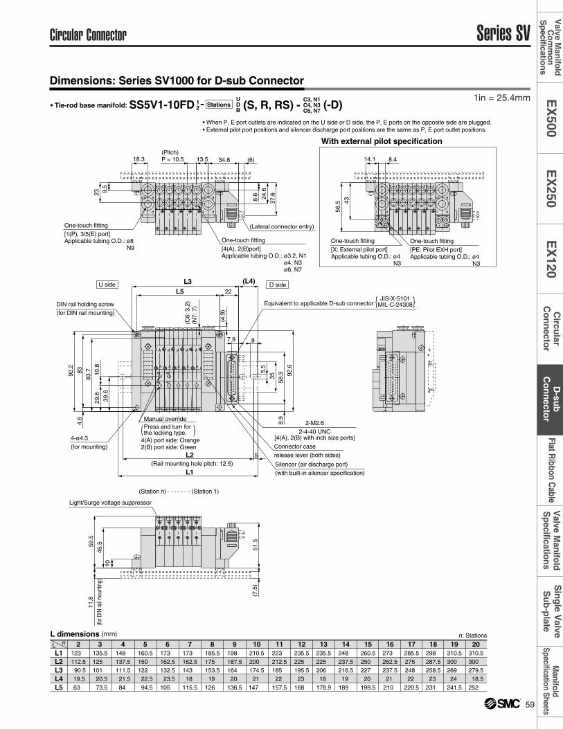
• Tie-rod base manifold: SS5V1-10FD - Stations (S, R, RS) - • When P, E port outlets are indicated on the U side or D side, the P, E ports on the opposite side are plugged. • External pilot port positions and silencer discharge port positions are the same as P, E port outlet positions.
L1L2L3L4L5
L n 2123 112.5 90.5 19.563
5160.5150 122 22.5 94.5
6173 162.5132.5 23.5105
7173 162.5143 18
115.5
8185.5175 153.519
126
9198 187.5164 20
136.5
10210.5200 174.521
147
11223 212.5185 22
157.5
12235.5225 195.523
168
13235.5225 206 18
178.9
14248 237.5216.519
189
15260.5250 227 20
199.5
16273 262.5237.521
210
17285.5275 248 22
220.5
18298 287.5258.523
231
19310.5300 269 24
241.5
20310.5300 279.5 18.5252
4148 137.5111.5 21.584
3135.5125 101 20.5 73.5
L dimensions n: Stations
(-D)
(Lateral connector entry)
DIN rail holding screw(for DIN rail mounting)
(Station n) (Station 1)
(Rail mounting hole pitch: 12.5)
JIS-X-5101MIL-C-24308Equivalent to applicable D-sub connector { }
One-touch fitting[1(P), 3/5(E) port]Applicable tubing O.D.: ø8
N9
A
B
A
B
A
B
A
B
AB
A
B
AB
B 2
A 4
One-touch fitting[4(A), 2(B)port]Applicable tubing O.D.: ø3.2, N1
ø4, N3ø6, N7
B 2
A 4
B 2 B 2 B 2 B 2
A 4 A 4 A 4 A 4
1 P
3/5 E
One-touch fitting[PE: Pilot EXH port]Applicable tubing O.D.: ø4
N3
One-touch fitting[X: External pilot port]Applicable tubing O.D.: ø4
N3
3/5
1 P
E3/5
1 P
E
U side D side
4-ø4.3(for mounting)
1 P
3/5 E
Connector caserelease lever (both sides)
2-M2.62-4-40 UNC
[4(A), 2(B) with inch size ports]
Light/Surge voltage suppressor
B 2
A 4
B 2
A 4
B 2
A 4
B 2
A 4
PE
X
PE
x
With external pilot specification
(7.5
)
18.3
1045
.59.
523
59.5
51.5
8.6 24
.6
(4.9
)
(C6:
3.2
)(N
7: 7
)
13.5(Pitch)P = 10.5
L3
34.8 (6)
L5
37.6
83.7
11.8
(for D
IN ra
il mou
ntin
g)
4356
.5
L2 5
L1
(L4)35
5.5
8
92.2
834.
6
29.6
10.8
39.6
22
8.9
58.9 92
.6
7.9
14.1 8.4
Manual overridePress and turn forthe locking type.
Silencer (air discharge port)(with built-in silencer specification)
4(A) port side: Orange2(B) port side: Green
Circular Connector Series SV
Dimensions: Series SV1000 for D-sub Connector
Manifold
Specification SheetsV
alve Manifold
Specifications
Flat Ribbon C
ableS
ing
le Valve
Su
b-p
lateD
-sub
Co
nn
ector
EX
250E
X120
Circu
larC
on
necto
rE
X500
Valve M
anifo
ldC
om
mo
nS
pecificatio
ns
1in = 25.4mm
(mm)
60 ®
Series SV D-sub Connector
Dimensions: Series SV2000 for D-sub Connector
( )
UDB
12
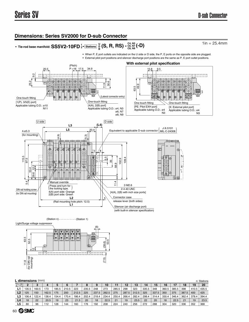
C4, N3C6, N7C8, N9• Tie-rod base manifold: SS5V2-10FD - Stations (S, R, RS) -
• When P, E port outlets are indicated on the U side or D side, the P, E ports on the opposite side are plugged. • External pilot port positions and silencer discharge port positions are the same as P, E port outlet positions.
L1L2L3L4L5
L n 2135.5125 106.418 80
5185.5175 154.419
128
6210.5200 170.423
144
7223 212.5186.4 21.5160
8235.5225 202.420
176
9248 237.5218.418
192
10273 262.5234.4 22.5208
11285.5275 250.421
224
12298 287.5266.419
240
13323 312.5282.4 23.5256
14335.5325 298.422
272
15348 337.5314.420
288
16360.5350 330.418
304
17385.5375 346.4 22.5320
18 398 387.5362.4
21336
19410.5400 378.4
19352
20435.5425 394.4 23.5368
4173 162.5138.4 20.5112
3160.5150 122.422 96
L dimensions n: Stations
(-D)
Manual overridePress and turn forthe locking type.
Silencer (air discharge port)(with built-in silencer specification)
4(A) port side: Orange2(B) port side: Green
P1
E3/5 3/5
B
A
2
4
B
A
2
4
B
A
2
4
B
A
2
4
B
A
2
4
(Station n) (Station 1)
DIN rail holding screw(for DIN rail mounting)
(Rail mounting hole pitch: 12.5)
(Pitch)P =16
One-touch fitting
[1(P), 3/5(E) port]Applicable tubing O.D.: ø10
N11
One-touch fitting[4(A), 2(B) port]Applicable tubing O.D.: ø4, N3
ø6, N7ø8, N9
A
B
AB
A
B
A
B
A
B
A
B
AB
1 P
E
(Lateral connector entry)
J-X-5101MIL-C-24308Equivalent to applicable D-sub connector { }
P1
E3/5 3/5
B
A
2
4
B
A
2
4
B
A
2
4
B
A
2
4
B
A
2
4
1 P
E
One-touch fitting[PE: Pilot EXH port]Applicable tubing O.D.: ø4
N3
One-touch fitting
[X: External pilot port]Applicable tubing O.D.: ø4
N3
U side D side
4-ø5.3(for mounting)
Connector caserelease lever (both sides)
2-M2.62-4-40 UNC
[4(A), 2(B) with inch size ports]
Light/Surge voltage suppressor
With external pilot specification
PE
x
PE
X
12
52.563
.5
(7.5
)
115.
5
109.
4
L5
20.5
9.2
25.2
17.5
53.5
(L4)L3
L2
L1
5
(4.9
)
11.9 30
.6
34.9
49.9
63.5
11.8
(for
DIN
rai
lm
ount
ing)
29.6
12.2
5.5
35
5.4
97.5
8
58.9
11.4
7.9
20.4
(5.3
)
53.4
102.
9
15.8 9.5
(39.
6)
(6)
1in = 25.4mm
(mm)
61®
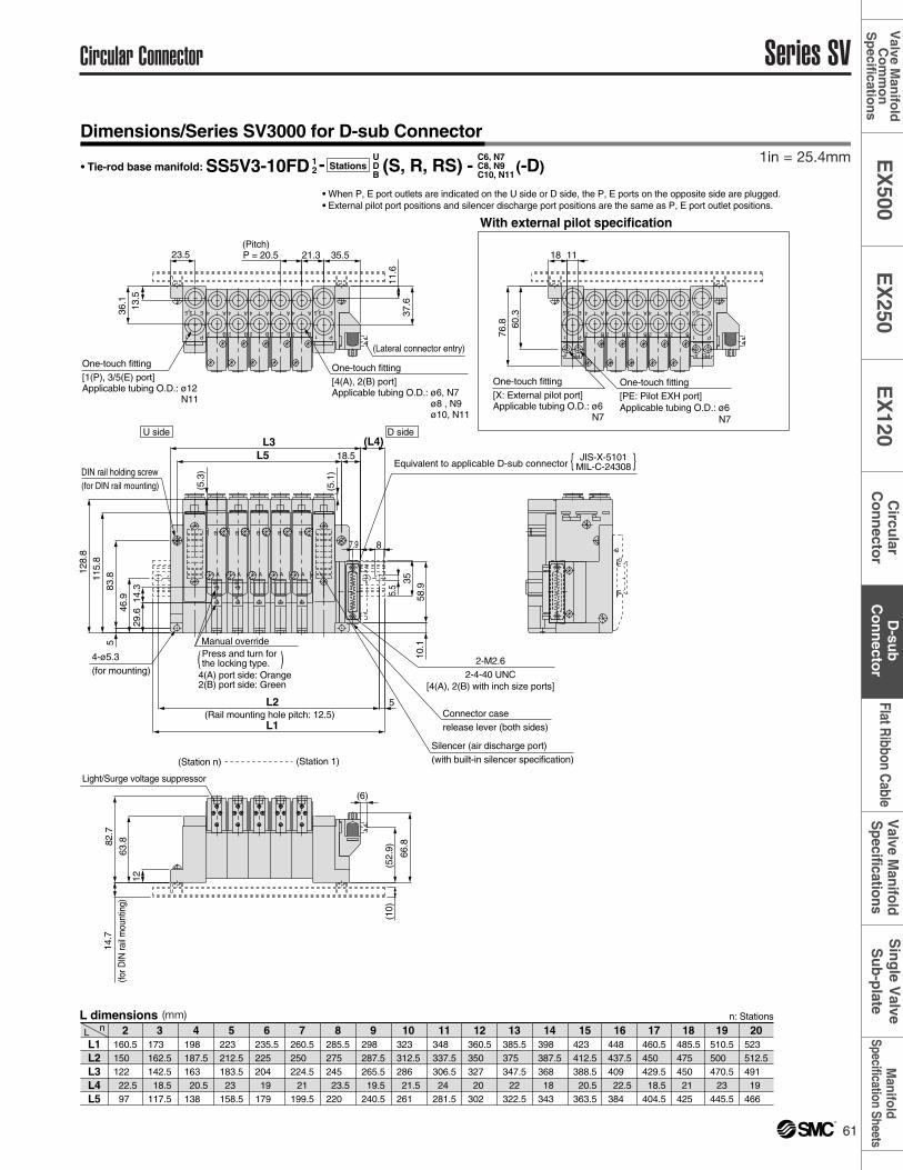
Dimensions/Series SV3000 for D-sub Connector
Circular Connector Series SV
( )
UDB
12
C6, N7C8, N9C10, N11
• Tie-rod base manifold: SS5V3-10FD - Stations (S, R, RS) - (-D)
• When P, E port outlets are indicated on the U side or D side, the P, E ports on the opposite side are plugged. • External pilot port positions and silencer discharge port positions are the same as P, E port outlet positions.
L1L2L3L4L5
L n 2160.5150 122 22.597
5223 212.5183.523
158.5
6235.5225 204 19
179
7260.5250 224.5
21199.5
8285.5275 245 23.5220
9298 287.5265.5 19.5240.5
10323 312.5286 21.5261
11348 337.5306.524
281.5
12360.5350 327 20
302
13385.5375 347.5
22322.5
14398 387.5368 18
343
15423 412.5388.5 20.5363.5
16448 437.5409 22.5384
17460.5450 429.5 18.5404.5
18485.5475 450 21
425
19510.5500 470.5
23445.5
20523 512.5491 19
466
4198 187.5163 20.5138
3173 162.5142.5 18.5117.5
L dimensions n: Stations
Manual overridePress and turn forthe locking type.
Silencer (air discharge port)(with built-in silencer specification)
4(A) port side: Orange2(B) port side: Green
(Station n) (Station 1)
DIN rail holding screw(for DIN rail mounting)
(Rail mounting hole pitch: 12.5)
(Pitch)
One-touch fitting[1(P), 3/5(E) port]Applicable tubing O.D.: ø12
N11
4-ø5.3(for mounting)
(Lateral connector entry)
U side D side
JIS-X-5101MIL-C-24308Equivalent to applicable D-sub connector { }
One-touch fitting[4(A), 2(B) port]Applicable tubing O.D.: ø6, N7
ø8 , N9ø10, N11
One-touch fitting[X: External pilot port]Applicable tubing O.D.: ø6
N7
One-touch fitting[PE: Pilot EXH port]Applicable tubing O.D.: ø6
N7
Connector caserelease lever (both sides)
2-M2.62-4-40 UNC
[4(A), 2(B) with inch size ports]
Light/Surge voltage suppressor
With external pilot specification
E
1 P
35
2 B
4 A
2 B
4 A
2 B
4 A
2 B
4 A
2 B
4 A E
1 P
35
AB
A
B
AB
A
B
A
B
A
B
E
1 P
35
2 B
4 A
2 B
4 A
2 B
4 A
2 B
4 A
2 B
4 A E
1 P
35
A
B
x PE X PE
1263
.882.7
115.
812
8.8
L5
21.3P = 20.523.5
13.5
36.1
11.6
37.6
83.8
5
35.5
L3
(5.1
)
8
66.8
(10)
35
5.5
L2
L1
5
(L4)
14.7
(for D
IN ra
il m
ount
ing)
60.3
76.8
14.3
29.646
.9
18.5
7.9
58.9
10.1
(5.3
)
18 11
(52.
9)
(6)
Manifold
Specification SheetsV
alve Manifold
Specifications
Flat Ribbon C
ableS
ing
le Valve
Su
b-p
lateD
-sub
Co
nn
ector
EX
250E
X120
Circu
larC
on
necto
rE
X500
Valve M
anifo
ldC
om
mo
nS
pecificatio
ns
1in = 25.4mm
(mm)
62 ®
Series SV D-sub Connector
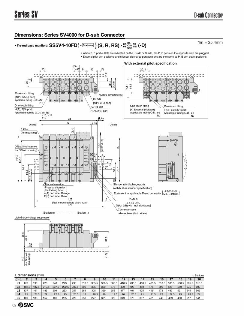
Dimensions: Series SV4000 for D-sub Connector
( )
UDB
12• Tie-rod base manifold: SS5V4-10FD - Stations (S, R, RS) -
• When P, E port outlets are indicated on the U side or D side, the P, E ports on the opposite side are plugged. • External pilot port positions and silencer discharge port positions are the same as P, E port outlet positions.
L1L2L3L4L5
L n 2173 162.5137 21
109
5248 237.5209 22.5181
6273 262.5233 23
205
7298 287.5257 23.5229
8310.5300 281 18
253
9335.5325 305 18.5277
10360.5350 329 19
301
11385.5375 353 19.5325
12410.5400 377 20
349
13435.5425 401 20.5373
14460.5450 425 21
397
15485.5475 449 21.5 421
16510.5500 473 22
445
17535.5525 497 22.5469
18560.5550 521 23
493
19585.5575 545 23.5517
20610.5600 569 24
541
4223 212.5185 22
157
3198 187.5161 21.5133
L dimensions n: Stations
02,03,
N9N11
C8,C10,C12,
(-D)
Manual overridePress and turn forthe locking type.
Silencer (air discharge port)(with built-in silencer specification)
4(A) port side: Orange2(B) port side: Green
(Pitch)P = 24
U side D side
(Lateral connector entry)
P1
E3
One-touch fitting[X: External pilot port]Applicable tubing O.D.: ø6
N7
One-touch fitting[PE: Pilot EXH port]Applicable tubing O.D.: ø6
N7
P1
E3/5
One-touch fitting[1(P), 3/5(E) port]Applicable tubing O.D.: ø12
N11One-touch fitting[4(A), 2(B) port]Applicable tubing O.D.: ø8, N9
ø10, N11ø12
Light/Surge voltage suppressor
(Station n) (Station 1)
DIN rail holding screw(for DIN rail mounting)
(Rail mounting hole pitch: 12.5)
4-ø6.2(for mounting)
Connector caserelease lever (both sides)
2-M2.62-4-40 UNC
[4(A), 2(B) with inch size ports]
JIS-X-5101MIL-C-24308Equivalent to applicable D-sub connector { }
P1
E3
Rc 1/4, 3/8[4(A), 2(B) port]
Rc 3/8[1(P), 3(E) port]
B
A
B
A
B
A
B
A
AB
B
A
AB
P1
E3/5
X PE x PE
A
B2
4 A
B2
4A
B2
4 A
B2
4 A
B2
4 A
B2
4 A
B2
4 A
B2
4 A
B2
4 A
B2
4
With external pilot specification
14.5
35
4024
61.885
.5
57.8
11
58.3
74.8
25 (6)
(43.
9)
16.2
(10)
29.6
17.5
56.3
98.2
148.
216
4.7
5.5 35
12.2
58.9
81.7
75
87.9
13.7
35.8
20
L2
L1
5
(5.4
)
L5 21.5
L3 (L4)
14.7
(for
DIN
rai
lm
ount
ing)
13.3
[for R
c 1/4
, 3/8
]
1in = 25.4mm
(mm)