Embed Size (px)
Citation preview
Natarajan Meghanathan et al. (Eds) : NeTCoM, CSIT, GRAPH-HOC, SPTM - 2014 pp. 79–96, 2014. © CS & IT-CSCP 2014 DOI : 10.5121/csit.2014.41307
DYNAMIC OPTIMIZATION OF OVERLAP-
AND-ADD LENGTH OVER MBOFDM
SYSTEM BASED ON SNR AND CIR
ESTIMATE
Nouri Naziha and Bouallegue Ridha
Innov’Com Laboratory, Higher School of Communications of Tunis, Sup'Com, University 7th November at Carthage, Tunisia.
ABSTRACT
An important role performed by Zero Padding (ZP) in multi-band OFDM (MB-OFDM) System.
This role show for low-complexity in résistance against multipath interference by reducing
inter-carrier interference (ICI) and eliminating the inter-symbol interference (ISI) Also, zero-
padded suffix can be used to eliminate ripples in the power spectral density in order to conform
to FCC requirements.
At the receiver of MB-OFDM system needs to use of a technique called as overlap-and-add
(OLA). Which maintain the circular convolution property and take the multipath energy of the
channel.
In this paper, we proposed a method of performing overlap-and-add length for zero padded
suffixes. Then, we studied the effect of this method, dynamic optimization of overlap-and-add
(OLA) equalization, on the performance of MBOFDM system on Bit Error Rate (BER) with
AWGN channel and Saleh-Valenzuela (S-V) Multipath channel Model.
In the dynamic optimization OLA, the Length of ZP depends on length of channel impulse
response (CIR). These measures, based on SNR, insert the ZP according to the measurement.
Dynamic optimization of length of ZP improves the Performance of MBOFDM system. In fact
we developed a technique to select the length of ZP as function of SNR and CIR
estimate(repetition). In our simulation this technique improve to 3 dB at BER=10-2
with a
multipath channels CM4.
KEYWORDS
UWB, ECMA-368, MB-OFDM, OLA, ZPS, SNR, CIR, BER.
80 Computer Science & Information Technology (CS & IT)
1. INTRODUCTION
Ultra-wideband (UWB) has tremendous potential for high-rate [1] low-power communication due to its high data rates and resistance to interference. Since its lowly beginning in the decade of 1940, UWB technology has traveled a wealthy path, from lab to military, back to lab [2] and this technology has received significant attention from industry, media and academia [3] especially in wireless universal serial bus (WUSB) and wireless personal area network (WPAN) domain [2]. The reason for all this excitement is that this technology promises to deliver high data rates that can scale from 110 Mbit/s at a distance of 10 meters up to 480 Mbit/s at a distance of two meters in realistic multipath environments all while consuming very little power communication and resistance to interference [1]. It is expected that UWB devices will provide low cost solutions [3].The United States Federal communications commission (FCC) officially defined UWB in 2002 as a signal with a 10 dB bandwidth of at least 500 MHz and a maximum equivalent isotropic radiated power spectral density (PSD) of no more than -41.3 dBm/MHz in the 3.1-10.6 GHz band [4]. FCC ruled that UWB system must have instantaneous spectrum of more than 500 MHz or more than 20% of its central frequency [2]. In order that UWB systems appear in the thermal noise floor of the existing narrowband services like GSM, GPS etc., and coexist with them without affecting their performance [5][6].Efficient utilization of such a large bandwidth of 7.5 GHz creates a huge challenge to the system designer community [2]. Furthermore the power constraints limits the range of communication to a short range only around 2 m to 15 m with scalable data rate of 53.3 Mbps to 480 Mbps. A promising new high-speed wireless communication technology, called Multiband-Orthogonal Frequency Division Multiplexing (MB-OFDM) approach, designers can overcome many of barriers [3] such as complexity, cost, power consumption, and flexibility. Pulsed multiband technique presented many disadvantages that can overcome if we use symbol which is much longer in time domain and integrating a modulation technique that can efficiently capture multipath energy [2]. MB-OFDM approach is the right candidate for this choice [7]. The main advantage of this approach is that information is processed over a much smaller bandwidth, this approach can reduce the system design complexity, the power consumption, cost, and also improving spectral flexibility which in turn helps UWB systems to follow global compliance [2][3]. Other advantages of this scheme include using lower-rate ADCs and simplifying the digital complexity. Systems built using this type of approach are often referred to as multiband systems [3]. The MB-OFDM is the first UWB technology obtained international standardization Thanks to their multiple benefits [8],[9] developed by the WiMedia alliance. Also this technology has been enabled by the FCC's recent allocation of 7500MHz. The MB-OFDM support data from 53.3 Mb/s to 480 Mb/s and divides the several gigahertz of spectrum allocated by the FCC into 14 bands, each with 528 MHz bandwidth. These bands are then bundled into 5 band groups with only the first defined as mandatory [10]. ECMA-368 is one of such principal standard employing MB-OFDM technique [11]. MB-OFDM based UWB system takes all the positives offered by the multi-banding scheme such as low power, low cost, simple analog design and also is capable of capturing sufficient multipath energy using a single RF chain due to adopted OFDM scheme [2].
Computer Science & Information Technology (CS & IT) 81
Multicarrier schemes are supported to high data rate. OFDM is an attractive air-interface for next-generation wireless network without complex equalizer. OFDM is an emerging multi-carrier modulation scheme. It has been adopted by several wireless standards such as IEEE 802.11a, IEEE 802.16 and HiperLAN2. OFDM is designed such a way that it sends data over hundreds of parallel carrier which increases data rate. OFDM distributes data across a large number of carries that are spaced apart at accurate frequencies is modulated by the data. The Orthogonal FDM (OFDM) reaps its own advantage to this approach [12], [13] in terms of spectral efficiency, narrow band interference (NBI) mitigation, excellent robustness against multipath channel, and smoothing the use of low complexity equalizer in receiver [2]. OFDM scheme suffered from inter-symbol interference (ISI) problem. ISI is distortion in a signal in which one symbol interferes with subsequent symbols, this will degrade performance of OFDM system. There are several methods for reducing the effects of ISI by affording time for reflection multipath energy mitigation and to allow a transmitter and a receiver for switching between different frequency bands. A receiving device can use an operation called overlap and add to restore the orthogonality. There are diversities of techniques to represent the noise at the receiver. Characteristically, more noise that affects the modulated signals, this noise can be measure with the distance error between the received signal and the ideal symbol associated with them. When the distance error is greater more difficult it becomes to map received signal to their associated ideal symbol and may prevent the communication to occur in some cases. Thus, the problem of relatively overly noise being added during overlap-and-add operation is very important issue that must be addressed with solutions that overcome the deficiencies of the prior technique. In this paper, we proposed a dynamic optimization of length of ZP technique based on SNR and CIR estimate, in addition, we evaluate its effects on performance of MB-OFDM system. Section II present a brief description of the main component of MB-OFDM system, especially by using Zero-Pad OFDM Signal and Overlap and adds operation over AWGN Channel and the SV/ IEEE 802.15.3a Channel Model. A dynamic overlap and add length technique based on SNR and CIR estimate is provided in Section III. In particular, we proposed our process of computing dynamic OLA size based on SNR and CIR estimation. Simulation Results are discussed in Section IV with four different channel models (CM) defined by the IEEE 802.15.3a. Finally, we conclude with a summary of this work given in Section V.
2. SYSTEM MODEL 2.1. MB-OFDM System
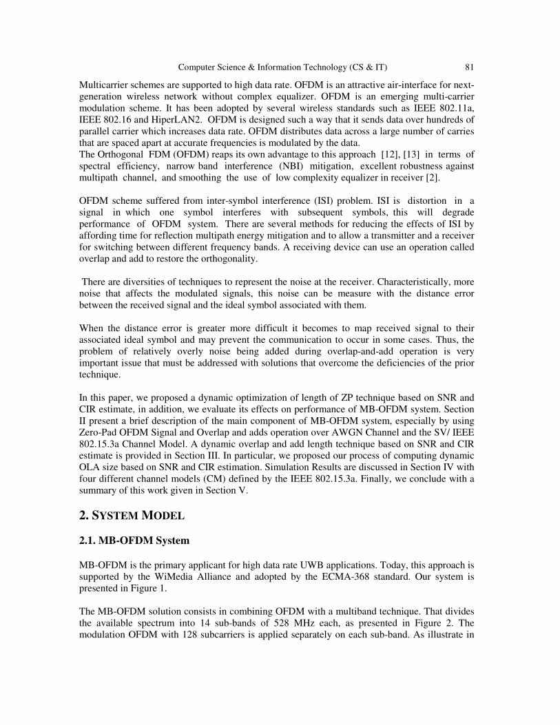
MB-OFDM is the primary applicant for high data rate UWB applications. Today, this approach is supported by the WiMedia Alliance and adopted by the ECMA-368 standard. Our system is presented in Figure 1. The MB-OFDM solution consists in combining OFDM with a multiband technique. That divides the available spectrum into 14 sub-bands of 528 MHz each, as presented in Figure 2. The modulation OFDM with 128 subcarriers is applied separately on each sub-band. As illustrate in
82 Computer Science & Information Technology (CS & IT)
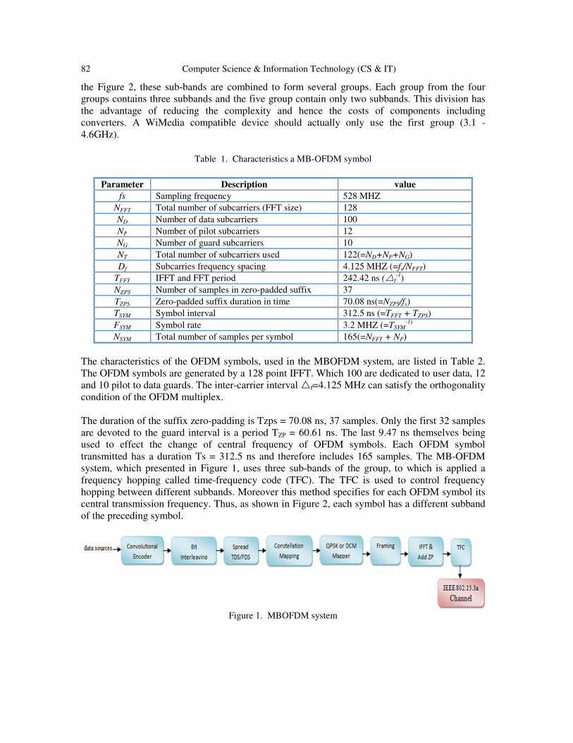
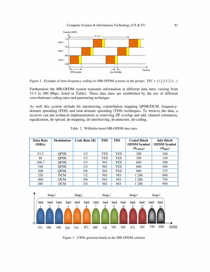
the Figure 2, these sub-bands are combined to form several groups. Each group from the four groups contains three subbands and the five group contain only two subbands. This division has the advantage of reducing the complexity and hence the costs of components including converters. A WiMedia compatible device should actually only use the first group (3.1 - 4.6GHz).
Table 1. Characteristics a MB-OFDM symbol
Parameter Description value
fs Sampling frequency 528 MHZ NFFT Total number of subcarriers (FFT size) 128 ND Number of data subcarriers 100 NP Number of pilot subcarriers 12 NG Number of guard subcarriers 10 NT Total number of subcarriers used 122(=ND+NP+NG) Df Subcarries frequency spacing 4.125 MHZ (=fs/NFFT)
TFFT IFFT and FFT period 242.42 ns (�f-1)
NZPS Number of samples in zero-padded suffix 37 TZPS Zero-padded suffix duration in time 70.08 ns(=NZPS/fs) TSYM Symbol interval 312.5 ns (=TFFT + TZPS) FSYM Symbol rate 3.2 MHZ (=TSYM
-1) NSYM Total number of samples per symbol 165(=NFFT + NP)
The characteristics of the OFDM symbols, used in the MBOFDM system, are listed in Table 2. The OFDM symbols are generated by a 128 point IFFT. Which 100 are dedicated to user data, 12 and 10 pilot to data guards. The inter-carrier interval �f=4.125 MHz can satisfy the orthogonality condition of the OFDM multiplex. The duration of the suffix zero-padding is Tzps = 70.08 ns, 37 samples. Only the first 32 samples are devoted to the guard interval is a period TZP = 60.61 ns. The last 9.47 ns themselves being used to effect the change of central frequency of OFDM symbols. Each OFDM symbol transmitted has a duration Ts = 312.5 ns and therefore includes 165 samples. The MB-OFDM system, which presented in Figure 1, uses three sub-bands of the group, to which is applied a frequency hopping called time-frequency code (TFC). The TFC is used to control frequency hopping between different subbands. Moreover this method specifies for each OFDM symbol its central transmission frequency. Thus, as shown in Figure 2, each symbol has a different subband of the preceding symbol.
Figure 1. MBOFDM system
Computer Science & Information Technology (CS & IT) 83
Figure 2. Example of time-frequency coding for MB-OFDM systems in the group1, TFC = {1,2,3,1,2,3,...}
Furthermore the MB-OFDM system transmits information at different data rates varying from 53.3 to 480 Mbps, listed in Table1. These data rates are established by the use of different convolutional coding rates and puncturing technique. As well this system include bit interleaving, constellation mapping QPSK/DCM, frequency-domain spreading (FDS) and time-domain spreading (TDS) techniques. To retrieve the data, a receiver can put technical implementation as removing ZP overlap and add, channel estimation, equalization, de-spread, de-mapping, de-interleaving, de-puncture, de-coding.
Table 2. WiMedia-based MB-OFDM data rates
Figure 3. UWB spectrum bands in the MB-OFDM solution
Data Rate
(MB/s)
Modulation Code Rate (R) FDS TDS Coded Bits/6
OFDM Symbol
(NCBP6S)
Info Bits/6
OFDM Symbol
(NIB6S)
53.3 QPSK 1/3 YES YES 300 100 80 QPSK 1/2 YES YES 300 150
106.7 QPSK 1/3 NO YES 600 200 160 QPSK 1/2 NO YES 600 300 200 QPSK 5/8 NO YES 600 375 320 DCM 1/2 NO NO 1 200 600 400 DCM 5/8 NO NO 1 200 750 480 DCM 3/4 NO NO 1 200 900
84 Computer Science & Information Technology (CS & IT)
2.2. The SV/ IEEE 802.15.3a Channel Model Since UWB channels take a some special propagation process and models which possess considerable difference with the conventional narrowband models, many investigation on the propagation and the channel models for UWB signaling have been delivered since the late 1990s [14]. The implementation of system simulation requires the use of model taking into account the effect of the channel on the link [15]. To study MBOFDM system, we will interest in the IEEE 802.15.3a broadband model. The IEEE 802.15.3a channel model was developed from a dozen all contributions based on different experimental measurements, carried out in residential indoor environment or office [16]. The proposed model is a model derived from Saleh and Valenzuela (SV) model [17] for indoor channels that Appropriate with the properties of UWB channels. The IEEE 802.15.3a model is a statistical model based on the assumption when the multipath components (MPCs) arrive in clusters, formed by the multiple reflections from the objects in the vicinity of receiver and transmitter [18]. a log-normal distribution is used for the multipath gain magnitude. Furthermore, independent fading is appreciated for each cluster and each ray within the cluster. The impulse response of the multipath channel is given by: h�t� = X ∑ ∑ β,�e ��,���� δ�t − T� − τ,���� �� (1)
Where l is the index of clusters, k is the index of paths within clusters, Tl is the delay of cluster l, τk,l is the delay of the k th path cluster l, relative to the arrival time of the first path of Tl cluster, βk,l is the amplitude coefficient of the path k in the cluster, θk,l is associated with path k in phase of the cluster (θk,l∈[0,2π)) and X is random variable amplitude that follows a log-normal type. The clusters, as well as the path arrival times, may be modeled according to Poisson random variables processes with different rates and have interarrival times that are exponentially distributed. The MPCs amplitudes follow a log-normal distribution, whereas the corresponding phase angles are a uniform random variable over [0,2π].The power decays exponentially with cluster decay likewise as excess delay within a cluster [18]. The UWB system modeling defined four different channel models (CM1 to CM4) each with decay factors and arrival rates selected to match different employment scenarios and to adapt line-of-sight (LOS) and non-line-of-sight (NLOS) cases. The channel models characteristics are presented in following table.
Table 3. IEEE 802.15.3a channel configurations
CM1 CM2 CM3 CM4
Distance Tx-Rx (m) < 4 < 4 From 4 To 10
Situation LOS NLOS
NLOS NLOS
τRMS (ns) 5.28 8.03 14.28 25
Computer Science & Information Technology (CS & IT) 85
2.3. CP vs ZP in OFDM based System
The use of the guard interval, which it is kind of cyclic prefix or zero-padding, is a clever solution which allows both to remove the ISI and to ensure the absence of ICI at the entrance of the FFT reception. The main advantage of ZP compared to CP for applications UWB that [15] the insertion of the cyclic prefix inserted in the temporal redundancy symbol which causes undulations in the PSD of the transmitted signal [8]. However, the use of zero padding does not provide temporal redundancy, so, PSD signal emitted is flat. Therefore, the ZP enhances the transmission power while maintaining the PSD mask [15] and hence to a longer distance [3]. ZP technique was therefore chosen for UWB applications instead cyclic-prefix.
2.4. Zero-Pad OFDM Signal
Used in the MB-OFDM approach, this technique involves inserting a guard interval of zero at the end of each OFDM symbol. This is called a type suffix-Zero Padding (ZP) [7]. Draws a series of samples is added to the end of each OFDM symbol at the output of the IFFT. The ith symbol ZP-OFDM szp(i) the output of the transmitter is given by [15]: Szp(i)=FzpxN(i), (2) With FZP=Izp F�� où Izp=[IN,0N×D]T , P×N is the matrix for adding ZP, 0N×D is a matrix of N×D zeros. Vector szp(i) is a vector of N samples from the time of operation applied to IFFT xN(i) tracking zero samples D. At the receiver input presented in fig.1, expression of the i-th symbol is given by:
rzp(i)= �� Fzp xN(i)+ �� ISI Fzp xN(i-1)+ ñp(i). (3) The intersymbol interference is eliminated by the matrix of zeros 0D×N of Fzp. Product �� ISI Fzp in last equation is zero. ��=[��0, ��zp] where ��0 and ��zp respectively represent firsts N and D Last column �� , This previous equation simplifies to:
rzp(i)=��0 �� xN(i)+ ñp(i). (4)
2.5. Overlap and Add (OLA)
However, unlike the CP-OFDM, the matrix ��0 is not circulating. An additional operation called Overlap and Add to make ��0 circulating is required. It consists to adding the last D samples received, corresponding to the ZP at the beginning of the symbol before the FFT demodulation. This therefore allows restoring the orthogonality between the subcarriers. The vector rzp(i) is split into two distinct parts. Its upper part is defined by dimension ru(i)= ��u sN(i) of N×1, its lower part is in turn defined by dimension rl(i)= �� l sN(i) of D×1 with ��u (respectively �� l) the corresponding matrix of dimensions N×N (respectively D×N) of ��0. N-D zeros are inserted after rl(i), the resulting vector is added to ru(i). This amount corresponds to the OLA is given by the following equation:
86 Computer Science & Information Technology (CS & IT)
rN(i)=ru(i)+! "l�i� 0��&'�×�) = *��u + ! ��l0��&'�×�)- ./�0� + *ñ1 + ! ñ2�0�3��&'�×4)-
= 56�7�8 96�:� + ;<6=>�:� (5) This equation obtained after the OLA has exactly the same form to the equation with the CP-OFDM except that the OLA colors noise term ;<6=>�:� slightly. In the same manner as in the case of CP-OFDM, a circulant matrix is diagonalized by then the demodulation FFT. At the receiver side, ZP removal demand uses of a method called as overlap and add (OLA) so as to capture the channel multipath energy and maintain the orthogonality in the received [2]. ZPS affords a mechanism to minimize the multipath energy and allows both transmitter and a receiver for switching between different frequency bands. 3. PROPOSED DYNAMIC OVERLAP-ADD TECHNIQUE BASED on SNR
and CIR ESTIMATE
3.1. Practical Estimation of Dynamic ZPS
We offer methods to decrease the quantity of noise. Which is introduced into the samples during an operation overlap-and-add is used with ZPS. The dynamic operations overlap and add can perform on the fly for each OFDM packet received, using the overlap-and-add length (OLAL) that provide better performance. In our work that perform multiband OFDM, operations of overlap and add are made when the data is received to overlap and add less than all of the samples of a zero-padded suffix for corresponding samples of symbol information before ZPS.
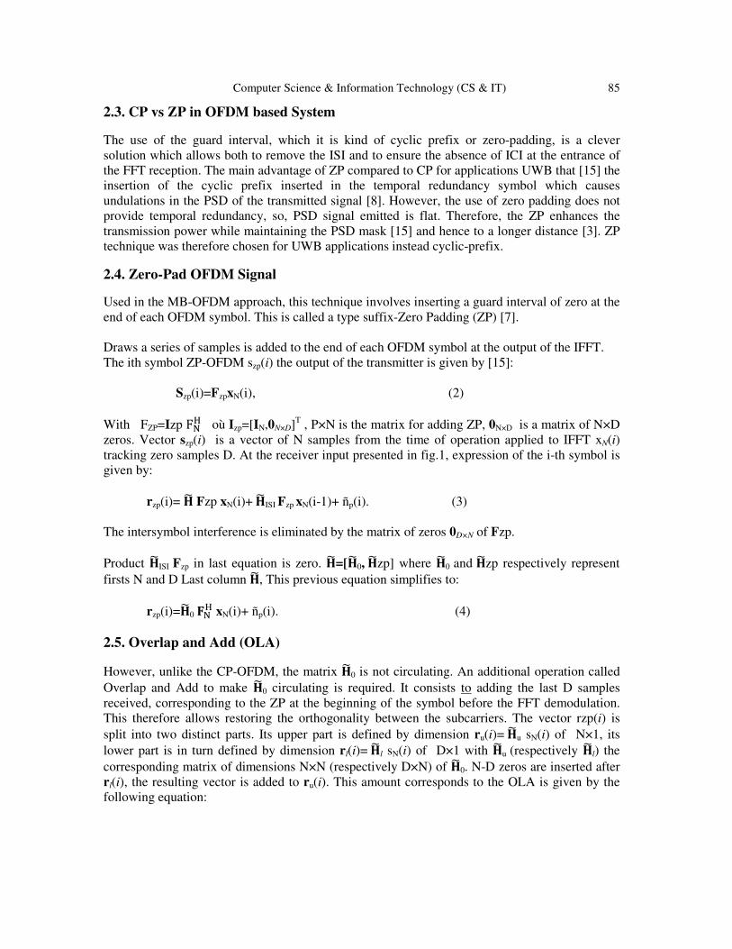
Figure 4. Dynamic OLA based on CIR and SNR estimate
As shown in Figure 1 the receiver comprises dynamic overlap and adding (OLA) receiving an incoming signal. Also dynamic OLA receives a channel impulse response (CIR) estimate and a signal-to-noise-ratio (SNR) estimate. In this paper, based on the CIR and SNR estimation, OLA dynamically performs activities of overlap-and-add and provides overlap-and-add samples modified and unmodified samples to FFT, OLA also conducts operations of overlap and add when CIR estimate, SNR estimate, or both are absent. Operations of overlap-and-add are portion of a convolution process using
Computer Science & Information Technology (CS & IT) 87
additional samples of ZPS to permit the multiplication in the frequency domain for use in forming the desired output. Spectral data extracted from FFT frequency of the incoming signal and outing frequency spectrum data to channel estimator. The channel estimator defines channel impulse response that is used by the frequency equalizer for removing the frequency shaping produced by the communication channel. The frequency spectrum data equalized to constellation de-mapper by the Frequency equalizer outputs. The frequency equalizer output is received by the constellation de-mapping, that converts the data of the frequency spectrum of the equalized to information symbols whether can be decoded by a decoder. 3.2. OLA Size based SNR and CIR Estimate
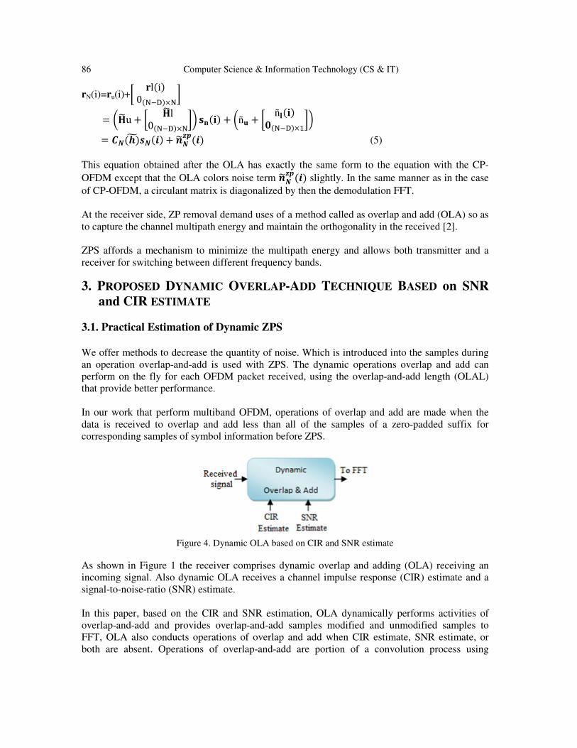
Dynamic OLA control (OLAC) which accepts an SNR estimate and CIR estimate. Based on the SNR and CIR estimates or a default value DEFVALM is 24, the OLAC sets the OLA length (OLAL) that is used in the overlap-and-add operation. Then buffer store the current OLAL at a time this new value can be used in the later iteration. Where OLAL value is 32, this number can vary depending upon the system. The following Figure illustrates the process to set the Dynamic OLA size.
Figure 5. Process to dynamically evaluate the OLAL length based on the estimated SNR and CIR
88 Computer Science & Information Technology (CS & IT)
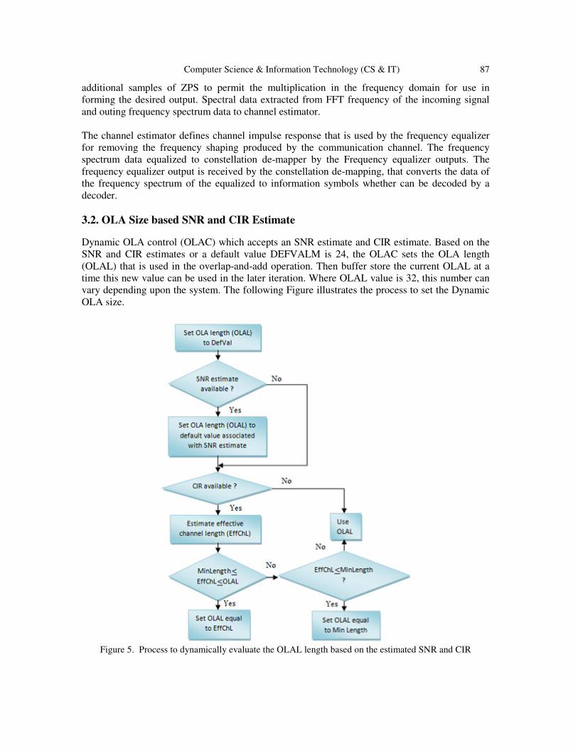
OLAC define if an SNR estimate is available for the packet being received, OLAC fix OLAL to a value which correspond to SNR estimate. The SNR assessments are divided into three categories high SNR, medium SNR, and low SNR and each category has a linear correspondence with a value OLAL presented in following table.
Table 4. Evaluate OLAL based on SNR estimate
SNR OLAL
high 24 Medium 16
Low 8
OLAC then control if the channel impulse response CIR is available. In the first case when an evaluation of CIR is not available OLAC employs OLAL like previously regulated based on the process presented in Figure 5. In the second case When the evaluation of CIR is available, OLAC evaluate the length of channel effective (EffChL). To continue with the process in Figure 5 OLAC determines then if EffChL is equal to or higher than a length minimum of OLA (OALML) and less than or equal to the current value of OLAL. When EffChl is not higher or equal to a OLA minimal length (OALML) or not lower or equal to the OLAL current value. OLAC specific if EffChL is less than or equal to OALML. Whenever EffChL is less than or equal to OALML OLAC put OLAL to OALML. When OLAC decide that EffChL is not less than or equal to OALML, OLAC uses the current value of OLAL (i.e.default value, DEFVALM). Exploiting the received CIR and SNR approximates, OLA perform a process like described in Figure 5. 3.3. SNR Estimate based EVM Technique
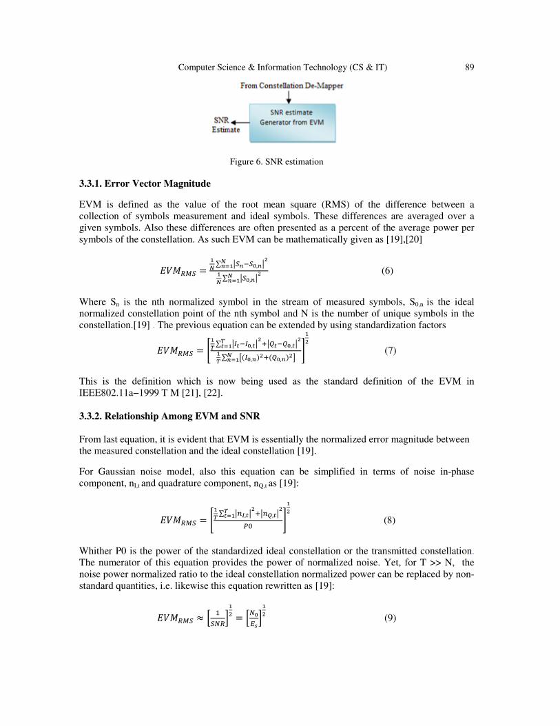
There are a variety of techniques to produce an assessment of SNR; in our system we chose an EVM technique. Figure 6 illustrate an evaluation of SNR generator based on a vector magnitude metric of error. SNR appreciate generator receive symbol from constellation de-mapper. This SNR set the error distance between the received symbol and their corresponding ideal constellation symbol which is specified by the type of modulation being used. This SNR set the error distance between the received symbol and the symbol of the corresponding ideal constellation that is specified by the type of modulation used. Based on distances from the error, the generator determines an amplitude error vector magnitude (EVM) metric and maps the EVM metric with an estimated SNR and provides SNR approximation. Generator of estimate SNR produces a more precise estimate SNR by the determination of the metric EVM for the data. Thus, OLAC uses a new more accurate assessment of SNR by performing a process as shown in Figure 5.
Computer Science & Information Technology (CS & IT) 89
Figure 6. SNR estimation
3.3.1. Error Vector Magnitude
EVM is defined as the value of the root mean square (RMS) of the difference between a collection of symbols measurement and ideal symbols. These differences are averaged over a given symbols. Also these differences are often presented as a percent of the average power per symbols of the constellation. As such EVM can be mathematically given as [19],[20]
?@ABCD = EF ∑ GDH&DI,HGJFHKE
EF ∑ GDI,HGJFHKE
(6)
Where Sn is the nth normalized symbol in the stream of measured symbols, S0,n is the ideal normalized constellation point of the nth symbol and N is the number of unique symbols in the constellation.[19] . The previous equation can be extended by using standardization factors
?@ABCD = LEM ∑ GNO&NI,OGJPGQO&QI,OGJMOKEE
M ∑ R�NI,H�JP�QI,H�JSFHKET
EJ (7)
This is the definition which is now being used as the standard definition of the EVM in IEEE802.11a−1999 T M [21], [22]. 3.3.2. Relationship Among EVM and SNR
From last equation, it is evident that EVM is essentially the normalized error magnitude between the measured constellation and the ideal constellation [19].
For Gaussian noise model, also this equation can be simplified in terms of noise in-phase component, nI,t and quadrature component, nQ,t as [19]:
?@ABCD = LEM ∑ GUV,OGJPGUW,OGJMOKE
X� TEJ (8)
Whither P0 is the power of the standardized ideal constellation or the transmitted constellation. The numerator of this equation provides the power of normalized noise. Yet, for T >> N, the noise power normalized ratio to the ideal constellation normalized power can be replaced by non-standard quantities, i.e. likewise this equation rewritten as [19]:
?@ABCD ≈ Z 4D[B\
EJ = Z[I
]^ \EJ (9)
90 Computer Science & Information Technology (CS & IT)
So as to establish relationship between BER and EVM, SNR in this equation can be expressed in terms of EVM as [19]:
_`a ≈ 4]bCJ (10)
3.4. CIR Estimation
The receiver contains an estimator for channel which provides a CIR for OLAC.
3.4.1. Cross-correlation
Detector generate CIR estimation a cross-correlation process and the averaging when a packet is received. With sequence data transmitted represented by x (n), the sequence data received can be characterized via the following equation: c�d� = ∑ e�f − g�ℎ�g� + d�f�[&4i�� (11) With n(i) is additive white Gaussian noise (AWGN) that has variance Г2, h(k) is the CIR. whether the sequence data is supposed to have ideal autocorrelation as shown as: ϕxx�m� = ∑ e�f + l�e�f� = m�l�[&4i�� (12) Next, the cross-correlation between the transmitted and received signals will be writen as: ϕrx�m� = ∑ e�f + l�e�f� = ĥ�l�[&4i�� (13) Where ĥ�l� is the appreciated CIR. This ĥ�l� is approximated on various symbols. These results are averaged and afforded to OLA. In this paper we use this method to estimate CIR. 3.4.2. Least mean square (LMS)
Detector produces a CIR estimate by employing a least means square (LMS) technique in the course of the channel estimation sequence. The LMS approximate may be defined by the following two equations as follows: ek=rk-yk (14)
ĥk+1 = ĥk+µekx*k (15)
Where ek is an appreciation error, rk is the received signal, yk is the approximation of received signal, xk is the channel estimation input sequence, and µ is an adaptative step-size. Monitoring performance and stability of LMS estimation usually depends on the adaptive step size, µ, and would be able to select the step-size that might work for a particular implementation.

Computer Science & Information Technology (CS & IT) 91
3.5. Effective channel length (EffChL)
OLAC estimate the effective channel length by determining the number of coefficients in the CIR estimating magnitude exceeding a threshold value which is X% of the largest magnitude coefficient. Figure 7 illustrates a channel impulse magnitude response and some of whose coefficients surpass a threshold.
Figure 7. Channel impulse magnitude response
The Figure 8 shows a method for setting a threshold value used to determine the effective channel length.
Figure 8. Setting a threshold value
X is 20% or in our system X is determined based on approximated SNR received by OLAC. In process OLAC set if an SNR estimate is ready for a packet. In the first case when an estimated SNR is available for a packet, OLAC regulated X to a value based on the approximated SNR. A larger value of X is used for a low SNR value, and vice versa.
Table 4. Evaluate X based on SNR estimate
SNR X
high < 20
Medium [20,40]
Low > 40
92 Computer Science & Information Technology (CS & IT)
In the second case when an assessment of SNR is not available for a package, OLAC set X to the default value, in our system, we use the default value of X is 20.
4. SIMULATION RESULTS AND DISCUSSION
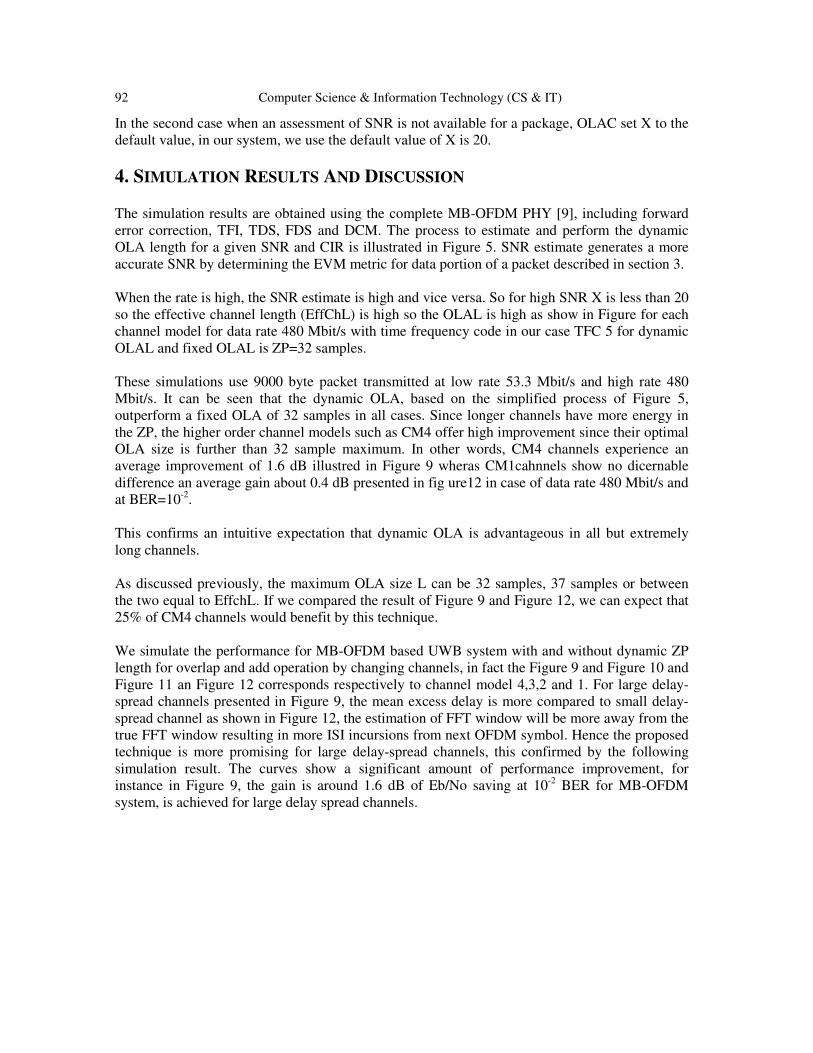
The simulation results are obtained using the complete MB-OFDM PHY [9], including forward error correction, TFI, TDS, FDS and DCM. The process to estimate and perform the dynamic OLA length for a given SNR and CIR is illustrated in Figure 5. SNR estimate generates a more accurate SNR by determining the EVM metric for data portion of a packet described in section 3. When the rate is high, the SNR estimate is high and vice versa. So for high SNR X is less than 20 so the effective channel length (EffChL) is high so the OLAL is high as show in Figure for each channel model for data rate 480 Mbit/s with time frequency code in our case TFC 5 for dynamic OLAL and fixed OLAL is ZP=32 samples. These simulations use 9000 byte packet transmitted at low rate 53.3 Mbit/s and high rate 480 Mbit/s. It can be seen that the dynamic OLA, based on the simplified process of Figure 5, outperform a fixed OLA of 32 samples in all cases. Since longer channels have more energy in the ZP, the higher order channel models such as CM4 offer high improvement since their optimal OLA size is further than 32 sample maximum. In other words, CM4 channels experience an average improvement of 1.6 dB illustred in Figure 9 wheras CM1cahnnels show no dicernable difference an average gain about 0.4 dB presented in fig ure12 in case of data rate 480 Mbit/s and at BER=10-2. This confirms an intuitive expectation that dynamic OLA is advantageous in all but extremely long channels. As discussed previously, the maximum OLA size L can be 32 samples, 37 samples or between the two equal to EffchL. If we compared the result of Figure 9 and Figure 12, we can expect that 25% of CM4 channels would benefit by this technique. We simulate the performance for MB-OFDM based UWB system with and without dynamic ZP length for overlap and add operation by changing channels, in fact the Figure 9 and Figure 10 and Figure 11 an Figure 12 corresponds respectively to channel model 4,3,2 and 1. For large delay-spread channels presented in Figure 9, the mean excess delay is more compared to small delay-spread channel as shown in Figure 12, the estimation of FFT window will be more away from the true FFT window resulting in more ISI incursions from next OFDM symbol. Hence the proposed technique is more promising for large delay-spread channels, this confirmed by the following simulation result. The curves show a significant amount of performance improvement, for instance in Figure 9, the gain is around 1.6 dB of Eb/No saving at 10-2 BER for MB-OFDM system, is achieved for large delay spread channels.
Computer Science & Information Technology (CS & IT) 93
Figure 9. Comparison performance between fixed OLA and Dynamic OLA in the case of CM4 for 480 Mbit/s with TFC
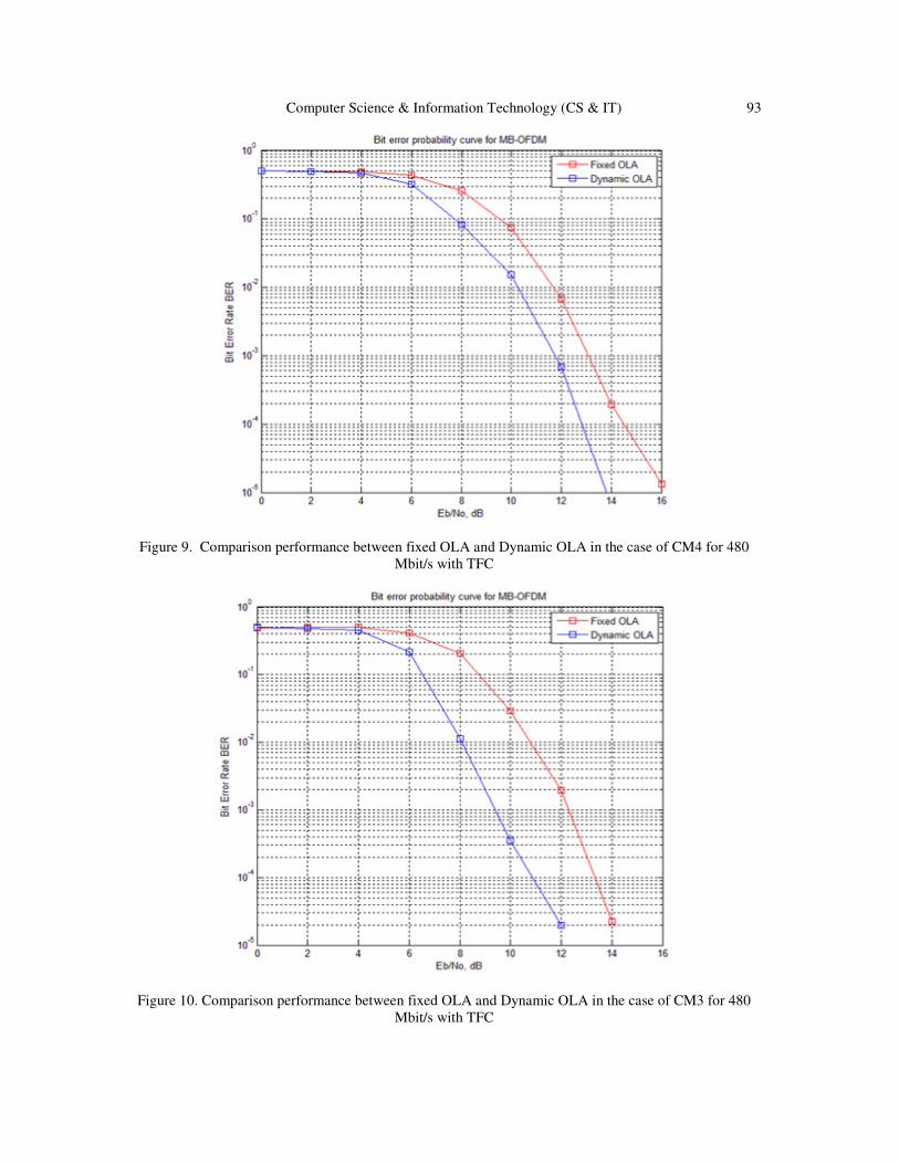
Figure 10. Comparison performance between fixed OLA and Dynamic OLA in the case of CM3 for 480 Mbit/s with TFC

94 Computer Science & Information Technology (CS & IT)
Figure 11. Comparison performance between fixed OLA and Dynamic OLA in the case of CM2 for 480
Mbit/s with TFC
Figure 12. Comparison performance between fixed OLA and Dynamic OLA in the case of CM1 for 480 Mbit/s with TFC
Computer Science & Information Technology (CS & IT) 95
5. CONCLUSION
In this paper, we proposed a method of performing overlap-and-add length dynamically for zero-padded suffixes. This method based on SNR and CIR estimate. Also our technique avoid picking up noise in the OLA process. It is shown that dynamic overlap-and-add technique is important for MBOFDM based receivers in terms of BER performance which tries to minimize ISI. In addition our simulation results indicate that Eb/No can be reduced by around 1.6 dB for the channel CM4 at 10-2 BER in multipath channels may be obtained by using dynamic OLA technique. Therefore the method is more promising and fruitful to channels having large delay spread channels(e.g. CM4) and provides a significant Eb/N0 improvement in the detection process. REFERENCES
[1] K.Siwiakand and D. McKeown, Ultra-wideband Radio Technology. Chichester, England: Wiley and
Sons, 2004. [2] P.Haseena bhanu, C. Venkata sudhakar. Performance Analysis of Aola technique for Wireless
communication. International Journal of engineering Trends and Technology (IJETT), May 2013 , Vol.4, n°5, pp. 1893-1898. ISSN: 2231-5381.
[3] P. Srilakshmi, N Gopi Chand. Analaysis and Implementation of UWB Receiver in Multi-Band OFDM systems. International Journal of Modern engineering Research (IJMER), July-Aug. 2012, vol.2, n°4, pp. 2641-2645.
[4] First Report and Order, Revision of Part 15of the Commission's Rules Regarding Ultra-Wideband Transmission Systems, Federal Communications Commission ET Docket 98-153, Feb. 2002.
[5] Saswat Chakrabarti, member, IEEE Adaptive overlap and add technique in MB-OFDM based UWB receiver design.
[6] Dr.R.S.kawitkat performance analysis of UWB system. [7] B. Muquet, Z. Wang, G. B. Giannakis, M. De Courvilleet P.Duhamel, “Cyclic Prefixing or Zero
Padding for Wireless Multicarrier Transmissions? “. IEEE Transaction on Communications, vol. 50, no12, pages 2136–2148, Décembre 2002.
[8] A. Batra, J. Balakrishnan, G. R. Aiello, J. R. Foersteret A.Dabak,” Design of a Multiband OFDM System for Realistic UWB Channel Environ-ments”. IEEE Transaction on Microwave Theory and Techniques, vol. 52, no9, pages 2132–2138, Septembre 2004.
[9] High Rate Ultra Wideband PHY and MAC Standard, ECMA International ECMA-368, Dec. 2005. [10] Darryn Lowe and Xiaojing Huang,”Adaptative Overlap-Add equalization for MB-OFDM Ultra-
wideband”, International Symposium on Communications and Information Technologies (ISCIT’06), Page 644 – 648, October 2006.
[11] Lowe, D & Huang, X, “Adaptive Overlap-Add Equalization for MBOFDM Ultra-Wideband”, International Symposium on Communications and Information Technologies (ISCIT), Bangkok, Thailand, 18-20 October 2006.
[12] A. Batra, et. al, “Multi-band OFDM physical layer proposal,”IEEE P802.15-03/268r0-TG3a, July 2003.
[13] June Chul Ron, Batra. A, and Waters. D, “Adaptive overlap-and-add techniques for MB-OFDM systems,” IEEE Asilomar Conference on Signals, Systems and Computers (ACSSC), Nov. 2007.
[14] Ayman Khalil, Matthieu Crussière and Jean-François Hélard, “Cross-Layer Resource Allocation for MB-OFDM UWB Systems”.
[15] GUÉGUEN Emeric.Etude et optimisation des techniques UWB haut débit multibandes OFDM . thèse de doctorat d’université. Rennes : Institut National des Sciences Appliquées de Rennes, Oct. 2009, 201 p.
[16] Jeff Foerster, “ Channel Modeling Sub-committee Report Final”. IEEE P802.15-02/490r1-SG3a, Février 2003.
96 Computer Science & Information Technology (CS & IT)
[17] A. Salehet R.Valenzuela, “A statistical Model for Indoor Multipath Pro-pagation”. IEEE Journal on Selected Areas in Communications (JSAC), vol. 5,no7, pages 128–137, Février 1987.
[18] A. A. M Saleh and R. A. Valenzuela, “A statistical model for indoor multipath propagation,” IEEE Journal on Selected Areas in Communications, vol. 5, pp. 128-137, Feb. 1987.
[19] Rishad Ahmed Shafik, Md. Shahriar Rahman, AHM Razibul Islam, “On the Extended Relationships Among EVM, BER and SNR as Performance Metrics”. 4th International Conference on Electrical and Computer Engineering, 19-21 December 2006.
[20] S. Forestier, P. Bouysse, R. Quere, A. Mallet, J. Nebus, and L. Lapierre. “Joint optimization of the power-aided efficiency and error vector mea-surement of 20-GHz pHEMT amplifier through a new dynamic bias-control method”. IEEE Transactions on Microwave Theory and Techniques, vol.52(no.4):pp.1132–1140, Apr. 2004.
[21] IEEE, IEEE Standard 802.11b-1999. IEEE Standard for Wireless LAN Medium Access Control (MAC) and Physical Layer (PHY) Specifications: High Speed Physical Layer Extension in the 2.4GHz Band.
[22] IEEE, IEEE Standard 802.11a-1999. IEEE Standard for Wireless LAN Medium Access Control (MAC) and Physical Layer (PHY) Specifications: High Speed Physical Layer in the 5GHz Band.
AUTHORS
Nouri Naziha
Was born in Sousse, Tunisia. She received the M.S degree in Telecommunications engineering in 2007 and the M.Sc. degree in Telecommunications in 2009 from the National Engineering School of Tunis (ENIT), Tunisia.She is currently working toward the Ph.D. Degree in Telecommunication systems at the High School of Telecommunication of Tunis (SUP’com) in the Laboratory research of Innovation of Communication and Cooperative Mobiles (Innov’COM), Tunisia. His current research interests include Wireless Communication, CDMA, MBOFDM and Ultra Wideband Systems. Bouallegue Ridha received the Ph.D degrees in electronic engineering from the National Engineering School of Tunis. In Mars 2003, he received the Hd.R degrees in multiuser detection in wireless communications. From September 1990 he was a graduate Professor in the higher school of communications of Tunis (SUP’COM), he has taught courses in communications and electronics. From 2005 to 2008, he was the Director of the National engineering school of Sousse. In 2006, he was a member of the national committee of science technology. Since 2005, he was the Innov’COM laboratory research in telecommunication Director’s at SUP’COM. From 2005, he served as a member of the scientific committee of validation of thesis and Hd.R in the higher engineering school of Tunis. His current research interests include wireless and mobile communications, OFDM, space-time processing for wireless systems, multiuser detection, wireless multimedia communications, and CDMA systems.


![Coherent Detection of Turbo-Coded OFDM Signals … · an OFDM frame when it is not present) ... synchronization for OFDM are given in [15]– ... Detection of OFDM signals,](https://img.pdfslide.us/doc/110x75/5ae5fd777f8b9a08778c6dfc/coherent-detection-of-turbo-coded-ofdm-signals-ofdm-frame-when-it-is-not-present.jpg)