Embed Size (px)
Citation preview
«t.»fci»»SS?"«S»*%« •-'
AFFDL.TR-71-e2 VOLUME II
■»,
00
Qi DESIGN STUDIES AND MODEL TESTS OF
JJ TBE STOWED TILT ROTOR CONCEPT
Volume II. Component Design Studies
B*mord t. Fry
ffw Bowirtf Compcmy, V«rtol Dnrision
ttCHNICAL REPORT AFFDL-TR-62
JULY 1971
D D C
SEP 7 1911 jjlj
Bkfiffiutioii kmlimltwl
AIR FORCE FLI6HT DYNAMICS LABORATORY AERONAUTICAL SYSTEMS DIVISION
AIR FORCE SYSTEMS COMMAND
WRIGHT-PATTERSON AIR FORCE BASE, OHIO RoSKoduced by
NATIONAL TECHNICAL INFORMATION SERVICE
Springfield. V». MISi
d> u
ÜNCLAgSIFIED ItemAtg O—iftfüoa
DOCUMENT CONTROL DATA • MD ol Mm. t^r W aktmtt m* M4»s«t« mmmtmHm* mumt bm mMMä «*•» *• •«••■11 -tmn I» clmttllimä)
I MlOWATIN« ACTIVITY (Ct^amf mttuH
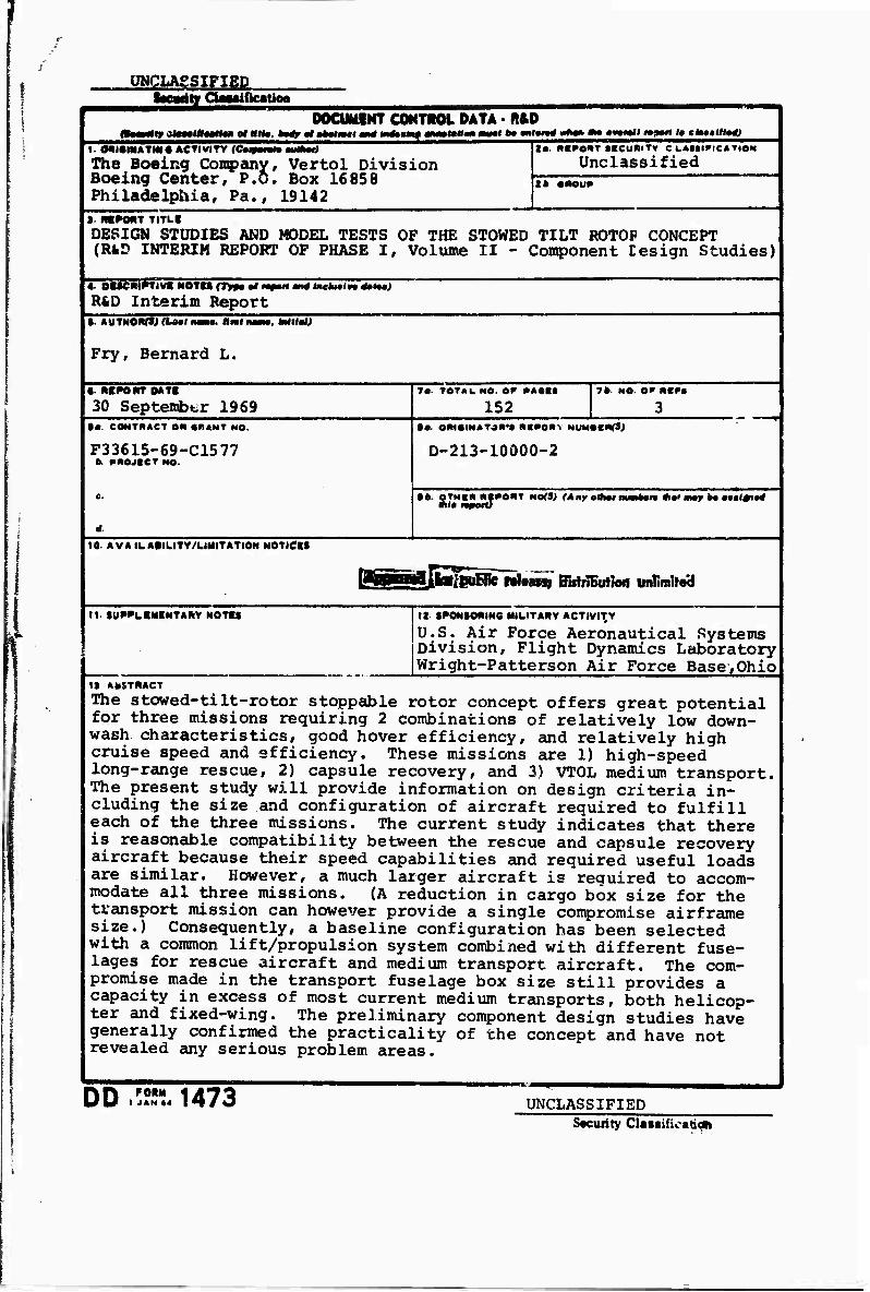
The Boeing Company, Vertol Division Boeing Center, P.O. Box 16858 Philadelphia, Pa., 19142
!• RKI»e<*T (BeuRiTv C LAMiriCATIOM
Unclassified t» »M)U*
» RB^ONT TITLI
DESIGN STUDIES AND MODEL TESTS OF THE STOWED TILT ROTOP CONCEPT (RfcD INTERIM REPORT OF PHASE I, Volume II - Component Cesign Studies)
4- DISCM^riVt NOTU (TM« 2 MpMt and teehMira <to«M>
R&D Interim Report •- AUTNORfSj AMI flmti •. lnlti«M
Fry, Bernard L.
•■ mPONTDATI
30 September 1969 7a- TOTAL. MO. er **•■•
152 7k NO. o* mmPM
• a. CONTRACT OR «RANT NO.
F33615-69-C1577 & RROJCCT NO.
in(S)
D-213-10000-2
tb OTNCR Rf^ORT NOfS; (Any olttar mmltm Si*'may b* •••l#i«d
tO AVAILABILITY/LIMITATION NOTlClt
Lfal BitliiEutien unlimUo'd
II. lUP^LBMINTAMY NOTU ia. SPOMSONiNO MILITARY ACTIVITY
U.S. Air Force Aeronautical Systems Division, Flight Dynamics Laboratory Wright-Patterson Air Force Base,Ohio
IS AbSTRACT
The stowed-tiIt-rotor stoppable rotor concept offers great potential for three missions requiring 2 combinations of relatively low down- wash, characteristics, good hover efficiency, and relatively high cruise speed and efficiency. These missions are 1) high-speed long-range rescue, 2) capsule recovery, and 3) VTOL medium transport, The present study will provide information on design criteria in- cluding the size and configuration of aircraft required to fulfill each of the three missions. The current study indicates that there is reasonable compatibility between the rescue and capsule recovery aircraft because their speed capabilities and required useful loads are similar. However, a much larger aircraft is required to accom- modate all three missions. (A reduction in cargo box size for the transport mission can however provide a single compromise airframe size.) Consequently, a baseline configuration has been selected with a common lift/propulsion system combined with different fuse- lages for rescue aircraft and medium transport aircraft. The com- promise made in the transport fuselage box size still provides a capacity in excess of most current medium transports, both helicop- ter and fixed-wing. The preliminary component design studies have generally confirmed the practicality of the concept and have not revealed any serious problem areas.
DD FORM t JAN «4 1473 UNCLASSIFIED
Security Cla«tific«tj«i

„ ■ o-E .?SC-*-
NOTICE
When Government drawings, specifications, or other data are used for any purpose
other than in connection with a definitely related Government procurement operation,
the United States Government thereby incurs no responsibility nor any obligation
whatsoever: and the fact that the government may have formulated, furnished, or in
any way supplied the said drawings, specifications, or other data, is not to be regarded
by implication or otherwise as in any manner licensing the bolder or an? other person
or corporation, or conveying any rights or permission to manufacture, uee, or sell any
patented Invention that may in any way be related thereto.
A-
Copies of this report should not be returned unless return is required by security
considerations, contractual obligations, or notice on a specific document.
UNCLASSIFIED "facufity CiMeificaUcw
u KtV WORM
UNK A
HOI.«
UNK •
«tot.« mr UNK C
STOWED TILT RCTOR
FOLDING ROTOR
CONVERTIBLE ENGINES
VTOL
TILT ROTOR
COMPOSITE AIRCRAFT
ADVANCED TECHNOLOGY
INSTRUCTIONS 1. ORIGINATING ACTIVITY: Entar the Mm* and MMTM* of the contractor, aubcontractor, grantea, Departraant of De- fenae activity or other organization (cotpotmt« tmthor) iaauiag the report. 2«. REPORT SECUHTY CLASSIFICATION: Enter the ovai» ali security claaaification of the report. Indicate whether "Restricted Data" is included. Maifcing is to be in accord- ance with appropriate security regulations. 26. GROUP: Automatic downgrading is specified in DoD Di- rective 5200.10 and Armed Forces Industrial Manual. Enter the croup number. Also, when applicable, show that optional markings have been used for Group 3 and Group 4 as author- ized. 3. REPORT TITLE: Enter the complete report title in all capita! tetters. Titles in alt cases should be unclassified. If a meaningful title cannot be selected without classifica- tion, show title classification in all capitals in parenthesis immediately following the title. 4. DESCRIPTIVE NOTES: If appropriate, enter the type of report, e.g., interim, progress, summary, annual, or final. Give the inclusive dates when a specific reporting period ia covered. 5. AUTHOR(S); Enter the name(s) of authoKs) as shown on or in the report. Enter taat name, first name, middle initial. If xilitary, show rank and branch of service. The name of the principal «uthor is an absolute minimum requirement 6. REPORT DATL: Enter the date of the report as day, month, year; or month, year. If more than one date appeara on the report, use date of publication. 7 a. TOTAL NUMBER OF PAGES: The total pege count should follow normal pagination procedures, i.e., enter the number of pages containing information. 7b. NUMBER OF REFERENCES: Enter the total number of references cited in the report. 8a. CONTRACT OR GRANT NUMBER: If appropriate, enter the applicable number of the contract or grant under which the report was written. 8b, 8c, &. -d. PROJECT NUMBER: Enter the appropriate military department identification, such as project number, subproject number, system numbers, task number, etc. 9a. ORIGINATOR'S REPORT NUMBER(S): Enter the offi- cial report number by which the document will be identified and controlled by the originating activity. This number muat be unique to this report. 9b. OTHER REPORT NUMBER(S): If the report haa been assigned any other report numbers (either by the originator or by the sponsor), also enter this number(s). 10. AVAILABILITY/LIMITATION NOTICES: Enter any lim- itations on further dissemination of the report, other than those
imposed by security classification, using atsndard statementa •uchaa:
(1) "Qialified requesters may obtain copies of this report from DDC"
(2) "Foreign announcement and disaemination of this report by DDC is not authorized."
(3) "U S. Government agencies may obtain copies of this report directly from DDC Other qualified DDC users shall request through
(4) "U. S. military agencies may obtain copies of this report directly from DDC Other qualified users shall request through
(5) "All distribution of this report is controlled. C^ial- ified DDC users shall request through
If the report hss been furnished to the Office of Technical Servieea, Department of Commerce, for aale to the public, indi- cate this fact and enter the price, if known. It SUPPLEMENTARY NOTES: Uae for additional explana- tory notes. 1Z SPONSO: IMG MILITARY ACTIVITY: Enter the name of the departmental project office or laboratory sponsoring (pay- ing lor) the reaearch and development. Include addreas. 13- ABSTRACT: Enter an abatract giving a brief and factual aummary of the document indicative of the report, even though it may alao appear elsewhere in the body of the technical re- port. If additional apace ia required, a continuation sheet shall be attached.
It ia highly desirable that the abstract of claaaified reports be unclessified. Each paragraph of the abatract ahall end with an indication of the military security clsssification of the in- formation in the paragraph, represented as (TS). (S). (C>, or (U).
There is no limitation on the length of the abatract. How- ever, the suggested length is from 150 to 225 words.
14. KEY WORDS: Key words are technically meaningful terms or short phrases that characterize a report and may be used as index entries for cataloging the report. Key worda muat be selected so that no security classification is required. Identi- fiers, such ss equipment model designation, trade name, militaiy project code name, geographic location, may be used aa key words but will be followed by an indication of technical con- text. The assignment of links, rules, and weights ia optional.
UNCLASSIFIED AFLC-WPAFB-JUL 66 3M Security Classification
DESIGN STUDIES AND MODEL TESTS OF
THE STOWED TILT ROTOR CONCEPT
Volume 11. Component Design Studies
Bernard L Fry
[KfiBKaa^ioC fcuBlie rtleasaj Bistributbn unÜmitec!
POREWORD
This report was prepared by The Boeing Company, Vertol Division, Philadelphia, Pennsylvania, for the Air Force Flight Dynamics Laboratory, Wright-Patterson Air Force Base, Ohio, under Phase I of contract P33615-69-C-1577. The contract objective is to de- velop design criteria and aerodynamic prediction techniques for the folding tilt rotor concept through a program of design studies, model testing and analysis.
The contract was administered by the Air Force Flight Dynamics Laboratory with Mr. Daniel E. Fraga (FV) as Project Engineer.
Acknowledgement is made to the following contributors to this volumes E. W. Gladfelter, W. C. Joiner, F. Renola, R. W. Sandford and J. W. Swanc^er.
The reports published under this contract for Design Studies and Model Tests of the Stowed Tilt Rotor Concept are:
Volume I Volume II Volume in vuxuiue xv
Volume V
Volume VI
Volume VII
Volume VIII
Parametric Design Studies Component Design Studies Performance Data for Parametric Study Aircraft Wiiid Tunnel Test of the Conversion Process of a Folding lilt Rotor Aircraft Using a Semi-Span Unpowered Model Wind Tunnel Test of a Powered Tilt Rotor Performance Model Wind Tunnel Test of a Powered Tilt Rotor Dynamic Model on a Simulated Free plight Suspension System Wind Tunnel Test of the Dynamics and Aero- dynamics of Rotor Spinup, Stopping and Fold- ing on a Semi-Span Folding Tilt Rotor Model Nummary of Structural Design Criteria and Aerodynamic Prediction Techniques
This report has been reviewed and is approved.
SRNEST J.»CROSS, JR. ERNES Lt. Colonel, USAF Chief, v/STOL Technology Division
11
TABLE OF CONTENTS
Section Page
| ' I. INTRODUCTION 1
II. SUMMARY 3
1. Wing 3 2. Nacelle 3 3. Tilt Mechanism 4 4. Rotor Blade 4 5. Rotor Hub and Folding Mechanism 5 6. Drive System 5
III. GENERAL DESIGN CRITERIA 7
1. Structures 7
IV. WING 17
1. Objectives 17 2. Design Criteria 17 3. Loads 19 4. Design 29 5. Stress Analysis ...... 47
, 6. Stiffness and Deflection 47 7. Conclusions and Recommendations 50
V. ROTOR BLADE 55
1. Objective 55 2. Design Criteria 56 3. Design 58 4. Loads Analysis 73 5. Stress Analysis . . , 80 6. Conclusions and Recommendations 90
VI. HUB AND BLADE FOLD MECHANISM 91
1. Objectives 91 2. Design Criteria 92 3. Design 93 4. Loads " 99
Apr). -yVOj Id pjOl,
111
Section Page
5. Stress Analysis 101 6. Nose Mount and Blade Retention Bearing Analysis 101 7. Stiffness and Deflection 107 8. Conclusions and Reconwüendations s ***.'. . 108
VII. DRIVE SYSTEM 109
1. Drive System Objective 109 2. Design Criteria 110 3. Drive System Design ..... Ill 4. Loads 116 5. Stress Analysis 122 6. Conclusions and Recommendations 125
VIII. ROTOR NACELLE AND TILTING MECHANISM 127
1. Objective - 127 2. Design 127 3. Conclusions and Recommendations 137
IX. CONCLUSIONS AND RECOMMENDATIONS 139
1. Wing 139 2. Nacelle 139 3. Tilt Mechanism 140 4. Rotor Blade 140 5. Rotor Hub and Folding Mechanism 141 6. Drive System 141
REFERENCES 143
APPENDIX: MILITARY SPECIFICATION REVIEW (See Volume III, APPENDIXES.)
IV
LIST OF ILLUSTRATIONS
Figure £252.
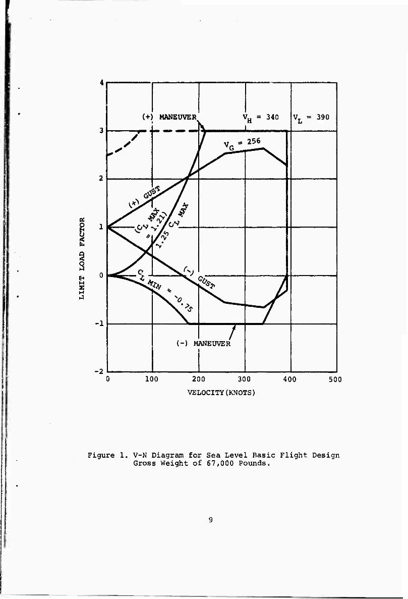
1 V-N Diagram for Sea Level Basic Flight Design Gross Weight of 67,000 Pounds 9
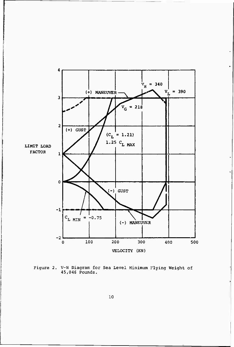
2 V-N Diagram for Sea Level Minimum Flying Weight of 45,046 Pounds 10
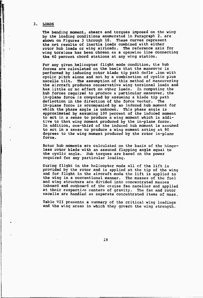
3 Stowed-TiIt-Rotor Ultimate Shear, Moment, and Torsion at Condition 1 (Ultimate Condition: 0.8 Nz Plus Roll Acceleration 67,000 Pounds Gross Weight, 3.0g Vertical Plus 1.5 Rad/Sec2) . . 20
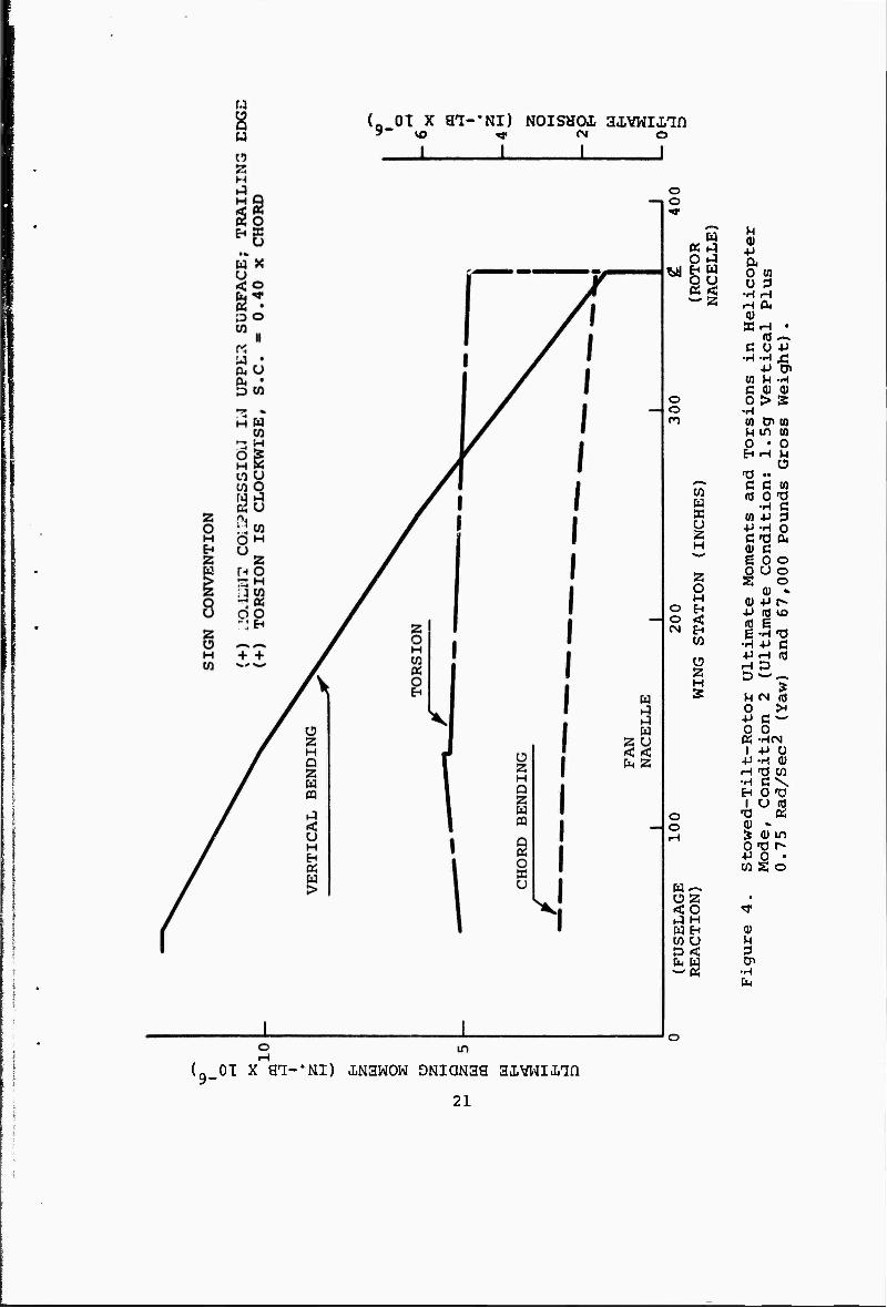
4 Stowed-TiIt-Rotor ultimate Moments and Torsions iii Helicopter Mode, Condition 2 (Ultimate 2
Condition: 1.5g Vertical Plus 0.75 Rad/Sec (Yaw) and 67,000 Pounds Gross Weight) 21
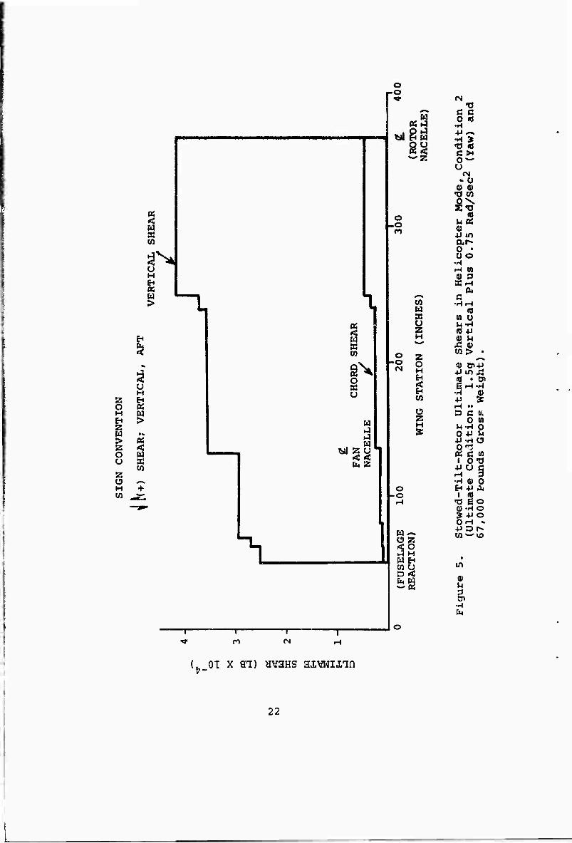
5 Stowed-TiIt-Rotor Ultimate Shears in Helicopter Mode, Condition 2 (Ultimate Condition: 1.5g Vertical Plus 0.75 Rad/Sec2 - Yaw and 67,000 Pounds Gross Weight) 22
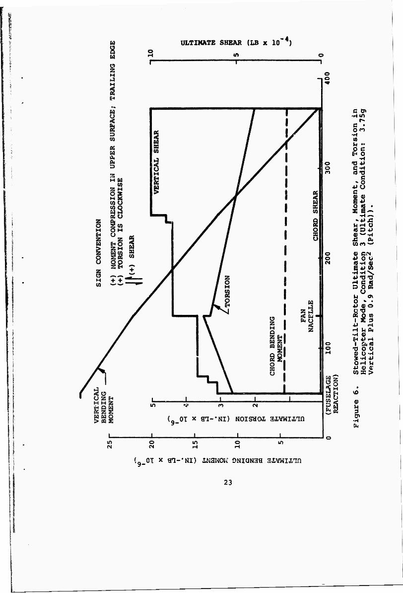
6 Stowed-TiIt-Rotor Ultimate Shear, Moment, and Torsion in Helicopter Mode, Condition 3 (Ultimate Condition: 3.75g Vertical Plus 0.9 Rad/Sec2 (Pitch)) 23
7 Stowed-Tilt-Rotor Ultimate Torsions at Condition 4 (Ultimate Condition: 1.5g Vertical Plus Maximum Cyclic, 67,000 Pounds Gross Weight, Torsion is (+) ClocKwise Moments and Shears: 1.5g Vertical Plus 0.75 Rad/Sec2) ... 24
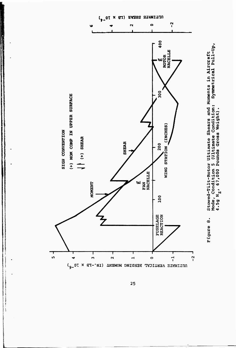
8 Stowed-Tilt-Rotor Ultimate Shears and Moments in Aircraft Mode, Condition 5 (Ultimate Condition: Symmetrical Pull-Up, 4.5g Ng, 67,000 Pounds Gross Weight) 25
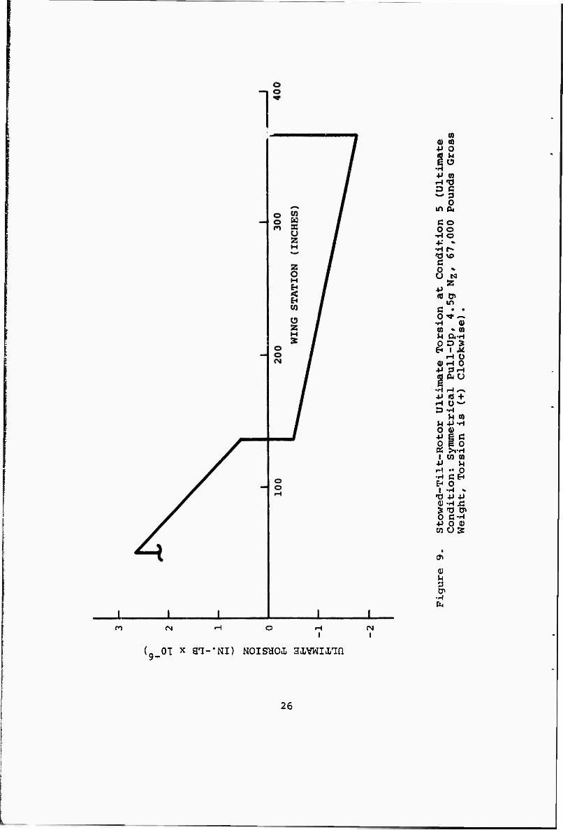
9 Stowed-Tilt-Rotor Ultimate Torsion at Condition 5 (Ultimate Condition: Symmetrical Pull-Up, 4.5g Ng, 67,000 Pounds Gross Weight, Torsion is (+) Clockwise) 26
Figure Page
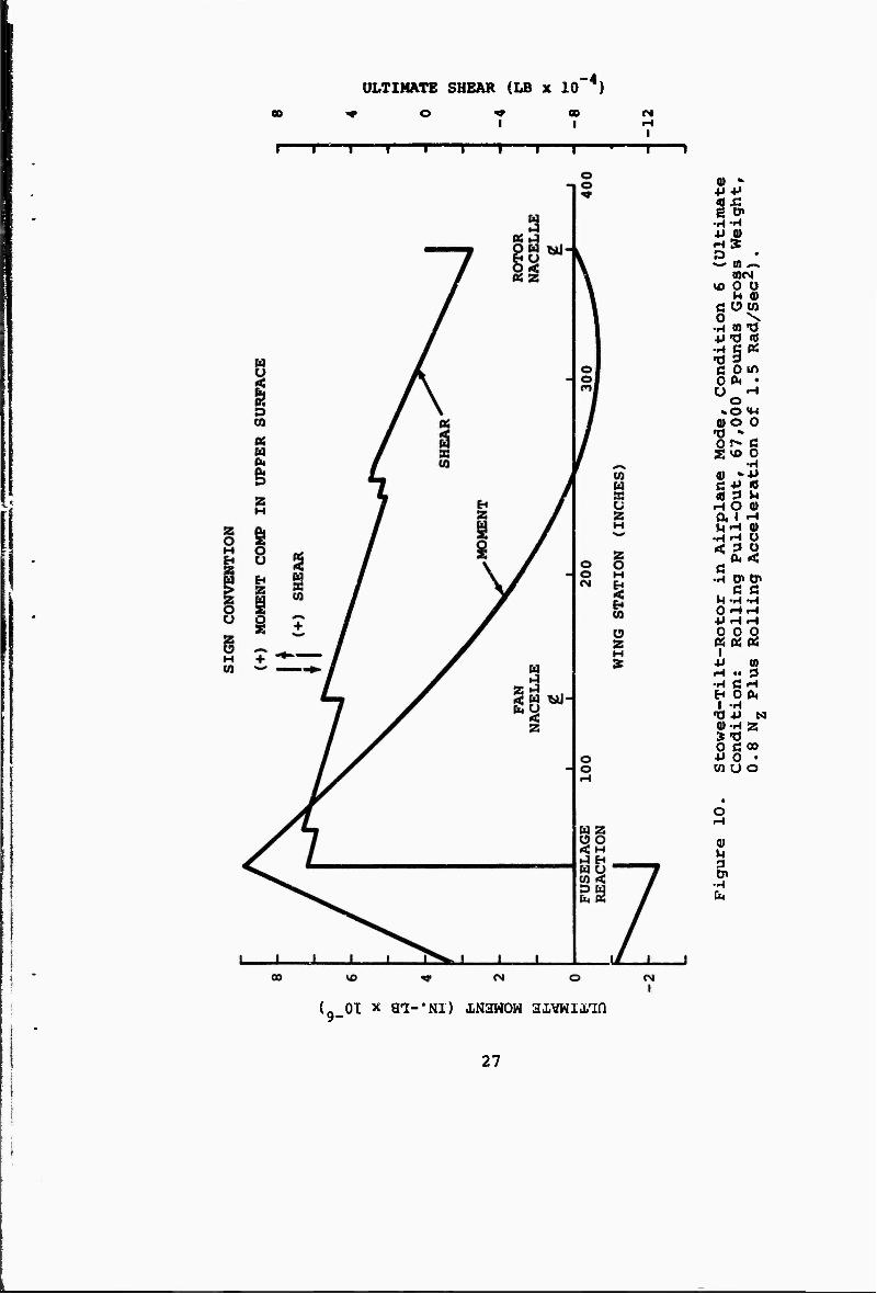
10 Stowed-TiIt-Rotor in Airplane Mode, Condition 6 (Ultiaate Condition: Rolling Pull-Out, 67,000 Pounds Gross Weight, 0.8 Mg, Plus Rolling Acceleration of 1.5g Rad/Sec2) .... 27
11 Baseline Aircraft Wing Geometry ........ 31
12 Wing Area Versus Taper Ratio 33
13 Baselin« Aircraft Typical Wing Construction . . 35
14 Baseline Aircraft Structural Box Geometry ... 37
15 Baseline Aircraft Wing Tip and Haoelle Pivot Support Structure (Sheet 2 of 2) . 40
15 Baseline Aircraft Wing Tip and Nacelle Pivot Support Structure (Sheet 2 of 2) 41
16 Baseline Aircraft Wing Station 50 (Sheet 1 of 2) 42
16 Baseline Aircraft Wing Station 50 (Sheet 2 of 2) 43
17 Baseline Aircraft Wing Station 150 45
18 Baseline Aircraft Wing Station 150 46
19 Stowed-TiIt-Rotor wing Stiffness 49
20 Stowed-TiIt-Rotor Twist for Unit Torsion Applied at Station 341.C and Deflections for lg Lift at the Rotor 51
21 Folding Tilt Rotor Blade Assembly (Sheet 1 of 3) 59
21 Folding Tilt Rotor Blade Assembly (Sheet 2 of 3) 61
21 Folding .lilt Rotor Blade Assembly (Sheet 3 of 3) 62
22 Stowed-Rotor Aircraft M-213 Fiberglass Rotor Blade Flap Stiffness (Design No. SR-B-2B) ... 65
23 Stowed-Rotor Aircraft M-213 Fiberglass Rotor Blade Chord Stiffness (Design No. SR-B-2B) . .66
vi
Figure Page
24 Stowed-Rotor Aircraft M-213 Fiberglass Rotor Blade Torsional Stiffness (Design No. SR-B-2B) ......... 67
25 Stowed-Rotor Aircraft M-213 Fiberglass Rotor Blade Pitch Inertia (Design No. SR-B-2B) ... 68
26 Stowed-Rotor Aircraft M-213 Fiberglass Rotor Blade Weight Distribution (Design No. SR-B-2B). 69
27 Stowed-Rotor Aircraft M-213 Rotor Blade Thickness Ratio (Design No. SR-B-2B, -3B) ... 70
28 Natural Frequency Spectrum Coupled Flap Lag Bending 71
29 Criteria for Hovering Stall Flutter Used to Substantiate Blade Chord, Blade Torsional Stiffness, and Control System Stiffness .... 72
30 Fiberglass Rotor Blade Flap and Chord Alternat- ing Bending Moment (Design No. SR-B-2B) .... 74
31 Rotor Blade Alternating Flap Bending Moment due to Cyclic (Design No. SR-B-2B) 75
32 Rotor Blade Alternating Chord Bending Moment due to Cyclic (Design No. SR-B-2B) 76
33 Rotor Blade Flap Bending Moment due to Precone Angle (Design No. SR-B-2B) 77
34 Fiberglass Rotor Blade Steady Chord Bending Moment (Design No. SR-B-2B) 78
35 Stowed Rotor Aircraft M-213 Fiberglass Rotor Blade Centrifugal Force (Design No. SR-B-2B) . 79
36 Stowed Rotor Aircraft M-213 Blade Static Moment Versus Blade Span (Design No. SR-B-2B) .... 81
37 Rotor Blade Flap Bending Moments for 2.5g Vertical Takeoff 82
38 Rotor Blade Chord Bending Moment for 2.5g Vertical Takeoff 83
39 Tensile Fatigue Stress Allowable Combined 45 Degree Cross-Ply and Unidirectional Fiberglass. 88
VI i
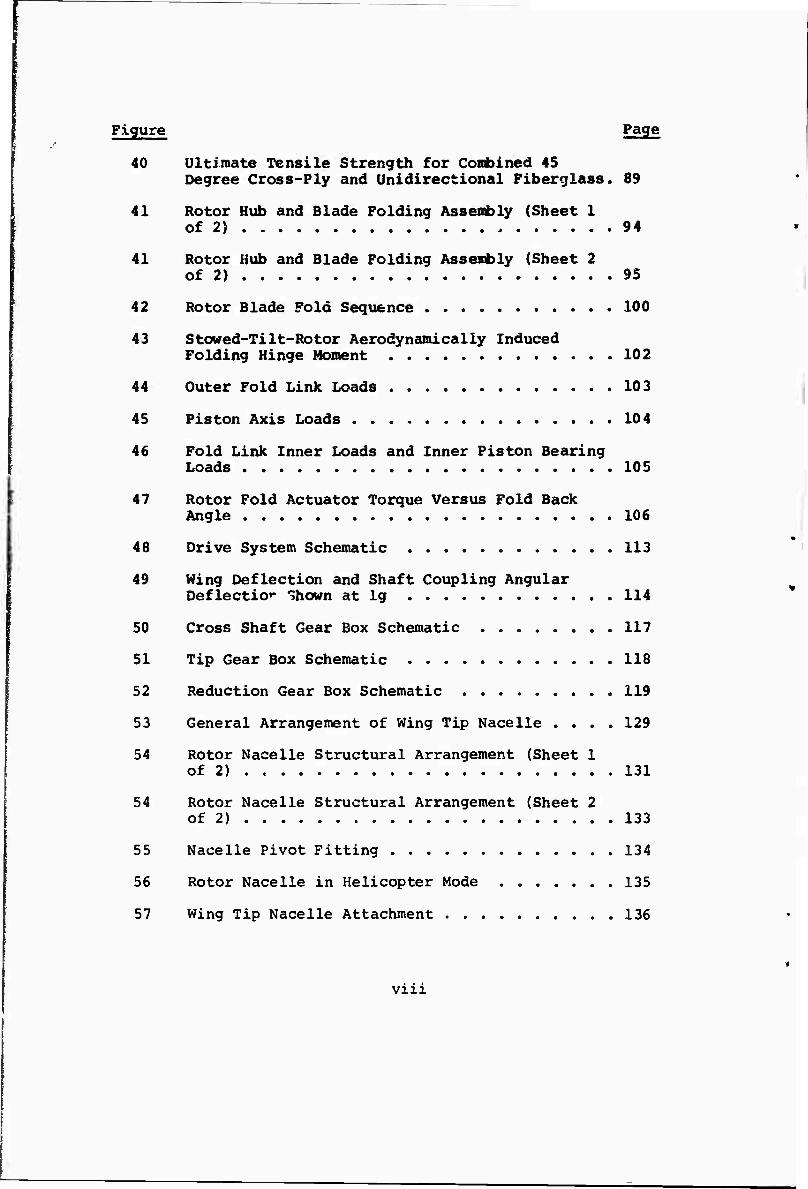
Figure Page
40 Ultimate Tensile Strength for Conblned 45 Degree Cross-Ply and Unidirectional Fiberglass. 89
41 Rotor Hub and Blade Folding Assembly (Sheet 1 of 2) 94
41 Rotor Hub and Blade Folding Assembly (Sheet 2 of 2) 95
42 Rotor Blade Fold Sequence . 100
43 Stowed-TiIt-Rotor Aerodynamically Induced Folding Hinge Moment 102
44 Outer Fold Link Loads 103
45 Piston Axis Loads 104
46 Fold Link Inner Loads and Inner Piston Bearing Loads 105
47 Rotor Fold Actuator Torque Versus Fold Back Angle 106
48 Drive System Schematic 113
49 Wing Deflection and Shaft Coupling Angular Deflection Shown at lg 114
50 Cross Shaft Gear Box Schematic 117
51 Tip Gear Box Schematic 118
52 Reduction Gear Box Schematic 119
53 General Arrangement of Wing Tip Nacelle .... 129
54 Rotor Nacelle Structural Arrangement (Sheet 1 of 2) . 131
54 Rotor Nacelle Structural Arrangement (Sheet 2 of 2) 133
55 Nacelle Pivot Fitting 134
56 Rotor Nacelle in Helicopter Mode 135
57 Wing Tip Nacelle Attachment 136
vm
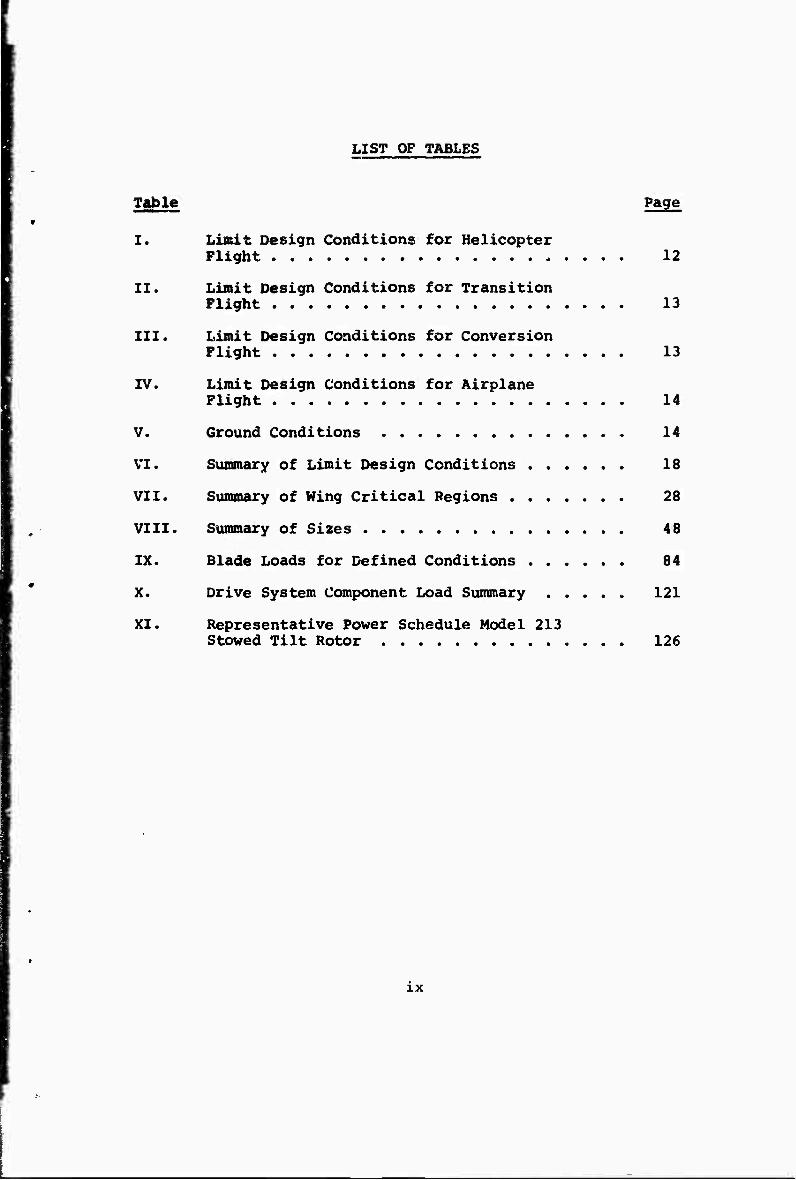
LIST OF TABLES
Table Page
I. Limit Design Conditions for Helicopter Flight ..... 12
II. Limit Design Conditions for Transition Flight 13
III. Limit Design Conditions for Conversion Flight 13
IV. Limit Design Conditions for Airplane Flight 14
V. Ground Conditions , 14
VI. Summary of Limit Design Conditions 18
VII. Summary of Wing Critical Regions 28
VIII. Summary of Sizes 48
IX. Blade Loads for Defined Conditions 84
X. Drive System Component Load Summary 121
XI. Representative Power Schedule Model 213 Stowed Tilt Rotor 126
IX
SECTION I
INTRODUCTION
This is the second of two volumes reporting on Phase I of a USAF Flight Dynamics Laboratory contract to detenaine design criteria for stowed-tiIt-rotor aircraft. The total program includes parametric design, preliminary component design studies, analyses, and wind tunnel testing.
Volume I described the parametric design studies leading to the selection of a baseline aircraft for component design studies. This volume covers the preliminary design of critical or unique components of the stowed-tiIt-roter con- cept including the wing, rotor hub and folding mechanism, rotor blades, drive system, and nacelle and tilting mechanism.
The geometry, mass distribution, and stiffness characteristics of the aircraft and its components, as well as identification of areas that require research, as determined from these studies, provide the necessary background for logical planning of the Phase II program of wind tunnel testing and analysis.
SECTION II
SUMMARY
This volume presents the results of the detailed component design studies carried out during the latter portion of the Phase I study. General preliminary design criteria is developed from proposed and existing military specifications. A number of potentially critical design conditions are speci- fied for the purpose of preliminary component design and evaluation. Design efforts are concentrated on the determi- nation of component concepts and their evaluation with respect to critical loading conditions, critical design areas such as space envelopes and mechanical complexity, and the determina- tion of problem areas peculiar to the stowed-tiIt-rotor vehicle concept. Components investigated in this study are the wing, nacelle, nacelle tilt mechanism, rctor blade, rotor hub, blade-fold mechanism and power-transmission system.
1. WING
Wing loading conditions for both helicopter and fixed-wing flight modes are investigated. The wing is found to be generally designed for the helicopter flight modes with the outboard section designed by torsional loads and the inboard section designed to normal bending loads. Conven- tional skin-stringer construction is utilized to facili- tate the design and analysis, and it is determined that a conventional wing designed to ultimate strength require- ments is dynamically adequate for the tip-mounted rotors, within the operational envelope desired. It is also determined that a wing of reasonable weight may be designed of conventional construction, and it is estimated that a lighter wing is obtainable if design and construction were to utilize some of the more advanced composite materials. There are no particular wing design problems resulting from the stowed-tilt-rotor configuration or concept.
2. NACELLE
A nacelle concept is presented which provides adequate structural load paths for all of the loads which can be anticipated at this time. Detailed structural analysis is not attempted since it is felt that this requires de- tailed study of the loads generated over the transition flight envelope. There does not appear to be any space problem with the folded-blade nacelle-structure transmission combination. For the purpose of the preliminary wing- nacelle dynamic investigations, the nacelle is considered
mmm PAGE BUNI(
to be a completely rxgid body between the rotor and the wing tip.
Nacelle preliminary design loads are estimated by applying the necessary vehicle balancing loads for a given flight maneuver at the two rotor hubs. Forces producing pitch, yaw» and roll accelerations are considered, as well as lift and trim. Secondary hub forces such as rotor induced moments, gyroscopic moments and rotor torque are also included in accordance with the particular maneuver under consideration.
3. TILT MECHANISM
A concept is shown in which the tilt actuators are com- pletely contained in the aft fixed portion of the wingtip nacelle. The s*.*. w-jack actuators are rough-sized for the hinge moments dictated by the preliminary loads analysis. The joint and actuators are assumed to be infinitely rigid for the purpose of preparing the dynamic analysis. A prob- lem is anticipated in determining the relative stiffness which actually exists in the wing-nacelle joint and the actuating system.
4. ROTOR BLADE
The rotor is of the hingeless type with an in-plane natural frequency below rotational speed. The flap frequency is about 1.2 times rotating frequency. The resulting low stiffnesses are designed to reduce blade loads and, there- fore, blade weight. The rotor blades were aerodynamically designed to provide a maximum hover figure of merit within the constraints dictated by folding requirements. The blade structure was designed to give adequate strength margins while exhibiting the desired natural frequency and stiffness characteristics. The selection of a "soft" hingeless rotor dictates a blade design with a low stiff- ness root-flexure region. By moving the start of this flexure region as far inboard as possible, a virtual flap- ping hinge offset is produced which gives acceptable dynamic and stress characteristics. Although the all- fiberglass blade does not possess adequate torsional stiff- ness to give the desired stall flutter margin, the inclu- sion of cross-ply boron in the flexure region produces a design with properties close to the desired values. A com- bination of differential nacelle tilt and cyclic for yaw control shows promise of drastically reducing the high cyclic stresses produced if yaw control is obtained with cyclic only.
A satisfactory hingeless rotor design appears to be possible which meets the requirements of satisfactory
stress levels, adequate control power, and desired frequency characteristics while still meeting the target weight.
5. ROTOR HUB AND FOLDING MECHANISM
The rotor hub and folding system was studied in sufficient detail to assess the feasibility of the concept. The effort wap concentrated on the critical or unique features of the design. Load and stress analysis was made to size the components of the folding mechanism and to ensure that the concept was feasible, within the space constraints.
The loads in the nose-mount bearings and the blade- retention bearings were calculated. These components carry relatively high bending morents, due to the use of a hingeless rotor, and have potentially critical space envelopes. The resulting sizes were found to be compatible with other constraints, such as minimum nacelle size for blade stowing.
The upper controls and their associated hydraulics were not analyzed. Sizing was based on experience with tilt- wing and tilt-rotor designs.
No major problems were uncovered as far as basic concept feasibility is concerned. The stiffness of the blade fold mechanism must be further studied however to ensure com- patibility with the structural dynamic requirements during folding and deployment of the blades.
6. DRIVE SYSTEM
Preliminary layouts of the drive system were prepared to define the location of gearboxes, shafts, and couplings. Criteria were established and torque and rotational speeds of components determined.
Design layouts and gear analysis were made to allow accurate sizing of the gears, with the goal of determining the gear- box envelopes and the shafting. The sized gearbox envelopes were used to provide design visibility of the space require- ments for related components.
Adequate initial sizing of these elements was essential, since the basic arrangement and sizing of key elements at the hir^'e region and rotor transmission region strongly influei.we the nacelle sizing.
The Appendix to this volume reviews the major military specifications with regard to their applicability to the stowed-tilt-rotor concept. Suggested changes and additions are included.
SECTION III
GENERAL DESIGN CRITERIA
1. STRUCTURES
a. Suianary
This section contains the general criteria for the structural design of the prop/rotor aircraft rotor blades, hub, wing, nacelle structure, and transmissions. MIL-A-8860 series and MIL-S-8698 specifications have been used to guide the selection of conditions. For preliminary design, only conditions which are generally critical should be selected for use.
b. Applicable Specifications
The structural design criteria shall generally be in accordance with the following military specifications with considerations given to the requirements for pre- liminary design.
(1) MIL-A-8860, "General Specification for Airplane Strength and Rigidity"
(2) MIL-S-8698, "Structural Design Requirements, Helicopter"
c. Flight Mode Definition
The aircraft flight modes are defined as follows:
(1) Helicopter Flight
All the lift is provided by the rotors, and the airspeed is less than SS knots in any direction.
(2) Transition Flight
Lift is provided by both the wing and rotors. The airspeed is between 35 knots and 170 knots. When the nacelle has reached the horizontal position, the transition flight mode is considered completed.
(3) Conversion Flight
All the lift is provided by the wing. The blades are either being folded, unfolded, or rotated at leas than 70 percent rpm.
PRECEDING PAGE BLANI^
Rescue Transport
45,046 45,774 67,000 67,000 67,000 67,000
74,000 56,021 68,467 78,522 80,387
(4) Airplane Flight
All the lift is provided by the wing. When the blades are in the extended position, the limiting speed is 250 knots; when the blades are stowed, the limiting speed is Vj,.
d. Design Gross Weight (Pounds)
Minimum flying gross weight Basic flight design gross weight Basic mission takeoff gross weight Alternate mission takeoff gw Landplane landing gross weight Maximum design gross weight (Ferry)
e. Factor of Safety
The yield factor of safety shall be 1.0 The ultimate factor of safety shall be 1.5.
f. Design Speeds
(1) For helicopter flight, the maximum forward, side- ward, and rearward speed shall be 35 knots.
(2) For transition flight, the speed varies from 35 knots to 170 knots.
(3) For conversion flight, the speed range is from 1.2 Vs flaps down to 50 knots above this speed, or 1.2 Vs flaps up, whichever is greater.
(4) For airplane flight, the maximum speed is 250 knots with the blades unfolded and VL when the blades are stowed. Maximum level flight speed (VH) is 340 knots. Maximum design limit speed (VL) is 390 knots. The speed for application of maximum gust intensity shall be VQ = VH Vs , where n is the maximum gust load factor at VH; VS is stalling speed for level flight at sea level in the basic configuration with power off.
9« V-N Diagram
Composite V-N diagram? for the flight modes at the basic flight design gross weight and minimum flying weights are shown in Figures 1 and 2. The airplane flight
a i u g
§ Es H X H
-1
-2
1 (+: MANEUVER 1 VH = 340 V i
VL = 390 j
A ^ Lx
^
i^L 256 1
. 6^ s-7 u^ r ^^ . • A^ .... rX «/^
> U^1 \t n^ \
(-) M /
ANEÜVER r 100 200 300
VELOCITY(KNOTS)
400 500
Figure 1. V-N Diagram for Sea Level Basic Flight Design Gross Weight of 67,000 Pounds.
LIMIT LOAD FACTOR
-1
-2
(■ •) MANEUVE]
% 7H = 340 j
^\ VL = 390 1
J /\* 211 N
1 (+) GUST^
/(CL / 1.25
» 1.21)
CL MAX
\yi V
1/ ̂
GUST J CL MIN ^
I
1
-0.75 (-) MANEl VER
100 200 300
VELOCITY (KN)
400 500
Figure 2. V-N Diagram for Sea Level Minimum Flying Weight of 45,046 Pounds.
10
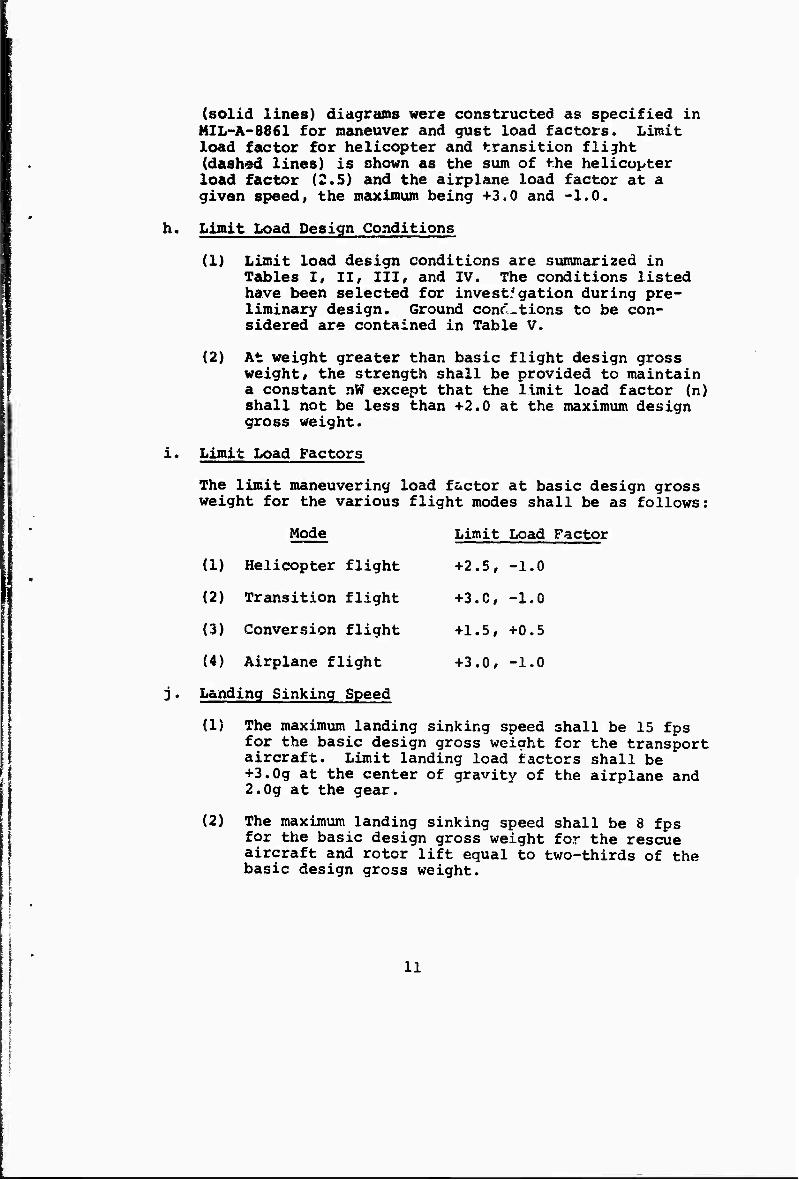
(solid lines) diagrams were constructed as specified in MIL-A-8861 for maneuver and gust load factors. Limit load factor for helicopter and transition flight (dashed lines) is shown as the sum of the helicopter load factor (2.5) and the airplane load factor at a given speed, the maximum being +3.0 and -1.0.
h. Limit Load Design Conditions
(1) Limit load design conditions are summarized in Tables I, 11/ III, and IV. The conditions listed have been selected for invest:gation during pre- liminary design. Ground conc'.tions to be con- sidered are contained in Table V.
(2) At weight greater than basic flight design gross weight, the strength shall be provided to maintain a constant nW except that the limit load factor (n) shall not be less than +2.0 at the maximum design gross weight.
i. Limit Load Factors
The limit maneuvering load factor at basic design gross weight for the various flight modes shall be as follows:
Mode Limit Load Factor
i
(1) Helicopter flight +2.5, -1.0
(2) Transition flight +3.C, -1.0
(3) Conversion flight +1.5, +0.5
(4) Airplane flight +3.0, -1.0
Landing Sinking Speed
(1) The maximum landing sinking speed shall be 15 fps for the basic design gross weight for the transport aircraft. Limit landing load factors shall be
| +3.0g at the center of gravity of the airplane and 2.0g at the gear.
(2) The maximum landing sinking speed shall be 8 fps for the basic design gross weight for the rescue aircraft and rotor lift equal to two-thirds of the basic design gross weight.
11
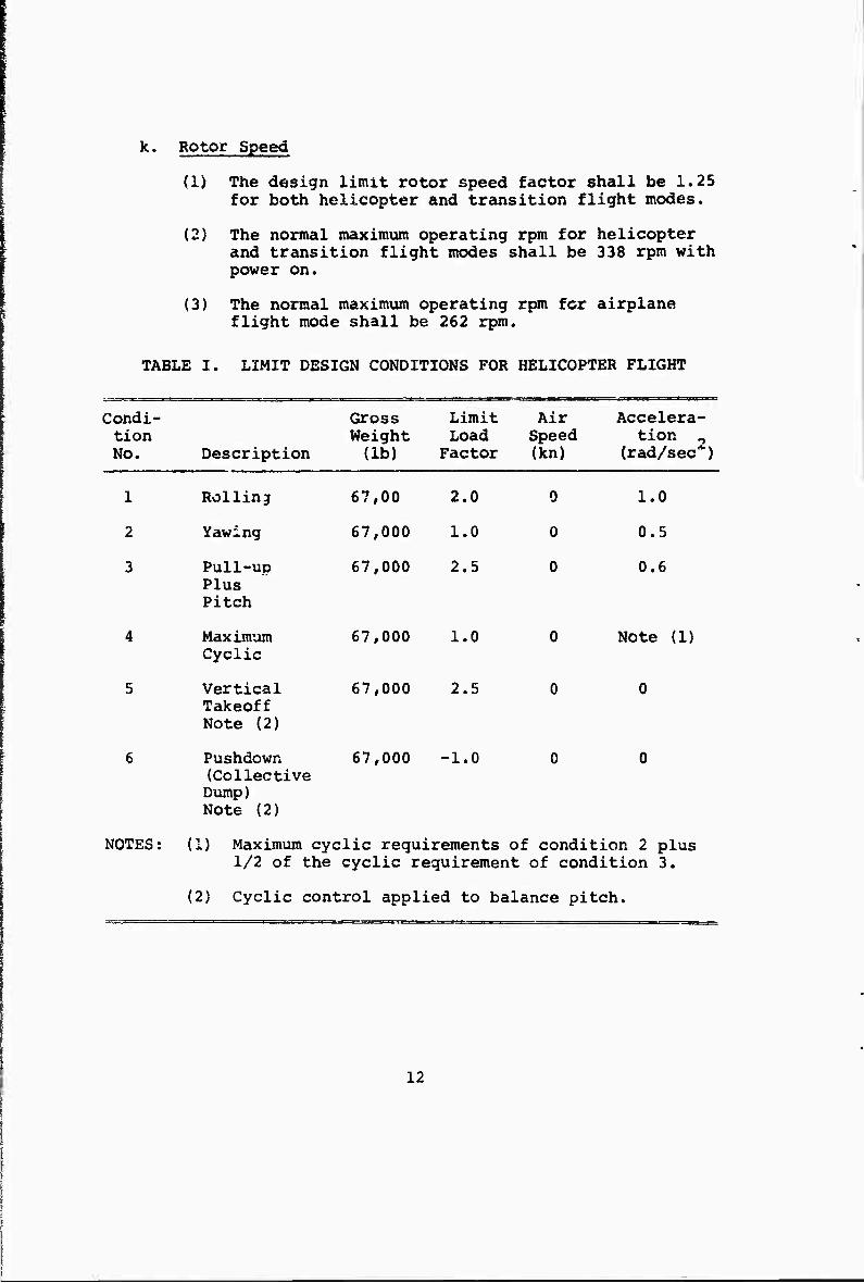
k. Rotor Speed
{1} The design limit rotor speed factor shall be 1.25 for both helicopter and transition flight modes.
(2) The normal maximum operating rpro for helicopter and transition flight modes shall be 338 rpm with power on.
(3) The normal maximum operating rpm for airplane flight mode shall be 262 rpm.
TABLE I. LIMIT DESIGN CONDITIONS FOR HELICOPTER FLIGHT
Condi- tion No. Description
r-r-TT-.1- ?--.^.-r=rri. '■■—!■
Gross Weight (lb)
Limit Load Factor
Air Speed (kn)
Accelera- tion 2
(rad/sec )
1 Rolling 67,00 2.0 0 1.0
2 Yawing 67,000 1.0 0 0.5
3 Pull-up Plus Pitch
67,000 2.5 0 0.6
4 Maximum Cyclic
67,000 1.0 0 Note (1)
5 Vertical Takeoff Note (2)
67,000 2.5 0 0
6 Pushdown (Collective Dump) Note (2)
67,000 -1.0 0 0
NOTES; (1) Maximum cyclic requirements of condition 2 plus 1/2 of the cyclic requirement of condition 3.
(2) Cyclic control applied to balance pitch.
12
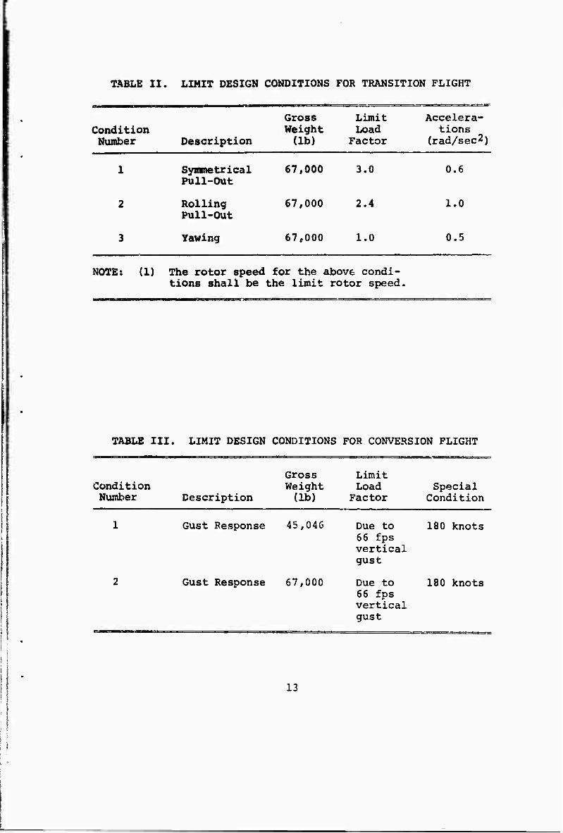
TABLE II. LIMIT DESIGN CONDITIONS FOR TRANSITION FLIGHT
Gross Limit Accelera- Condition Weight Load tions Number Description (lb) Factor (rad/sec2)
1 Symmetrical Pull-Out
67,000 3.0 0.6
2 Rolling Pull-Out
67,000 2.4 1.0
3 Yawing 67,000 1.0 0.5
NOTE: (1) The rotor speed for the above condi- tions shall be the limit rotor speed,
TABLE III. LIMIT DESIGN CONDITIONS FOR CONVERSION FLIGHT
Condition Number Description
Gross Weight (lb)
Limit Load
Factor Special
Condition
1 Gust Response 45,046 Due to 66 fps vertical gust
180 knots
2 Gust Response 67,000 Due to 66 fps vertical gust
180 knots
13
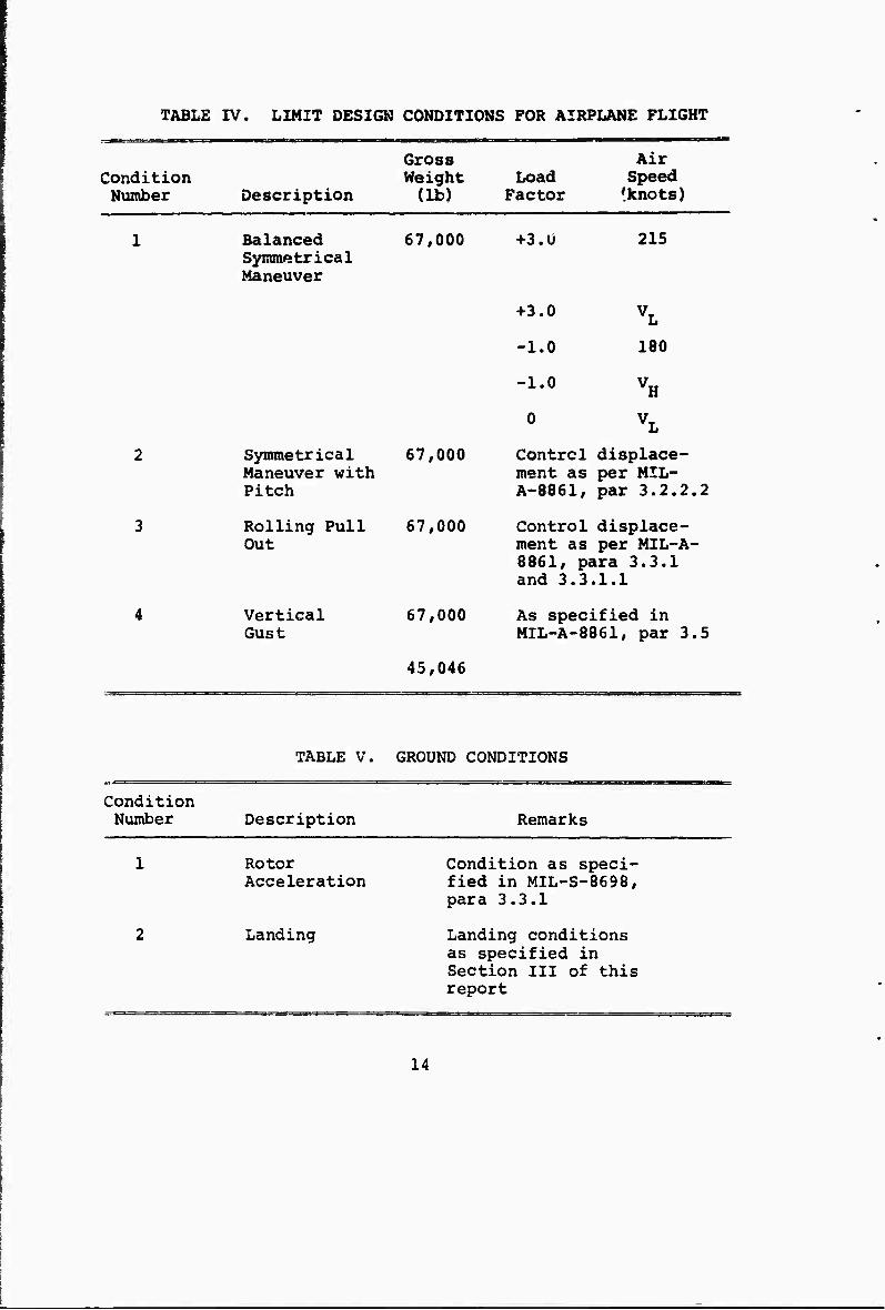
TABLE IV. LIMIT DESIGN CONDITIONS FOR AIRPLANE PLIGHT
Condition Number Description
Gross Height (lb)
Load Factor
Air Speed 'knots)
Balanced Symmetrical Maneuver
67,000
Symmetrical Maneuver with Pitch
Rolling Pull Out
Vertical Gust
67,000
67,000
67,000
45,046
+3.Ü
+3.0
215
-1.0 180
-1.0 vH
0 VL
Control displace- ment as per MIL- A-8861, par 3.2.2.2
Control displace- ment as per MIL-A- 8861, para 3.3.1 and 3.3.1.1
As specified in MIL-A-8861, par 3.5
TABLE V. GROUND CONDITIONS
Condition Number Description Remarks
Rotor Acceleration
Landing
Condition as speci- fied in MIL-S-8698, para 3.3.1
Landing conditions as specified in Section III of this report
14
1. Fatigue Design Conditions
(1) Basic Fatigue Schedule
The 3towed-tilt-ro*;or aircraft is exposed to fatigue damage both as a fixed-wing and a rotary- wing aircraft, as well as fatigue due to the large tilting nacelle mass at the tip of the wing. Fatigue damage shall be evaluated as specified in MIL-S-8698, MIL-A-8860 and ASD-TR-66-57.
The basic fatigue schedule shall be based on air- craft usage as defined by the mission profiles. Damage assessment shall be based on a cumulative damage theory. The significant conditions affect- ing the fatigue performance of the wing are the repeated maneuvers and atmospheric turbulence at low altitudes and the relatively large number of ground-air-ground cycles. The significant condi-
% tions affecting the fatigue performance of the I nacelle structure are repeated maneuvers with the I vehicle in the airplane mode, ground-air-ground I cycles and rotor loads. The significant condi- 1 tions affecting the fatigue performance of the 1 dynamic system are the prop/rotor cyclic control
and airplane flight with inclination of the prop/ rotor axis. The dynamic system is considered to include the prop/rotor blade, hub, controls and drive and drive system.
(2) Service Life
The service life of the wing and nacelle structure shall be 10,000 hours. The service life on dynamic system components shall be 3,600 hours, except as indicated below. Airplane integrity shall be established along the guide lines of ASD-TR-66-57, "Air Force Structural Integrity Program Requirements".
The Lio design life for the individual drive sys- tem bearings shall be established based on the mean time between removal (MTBR) of the desired trans- mission. This means that the total bearing system life, when combined with other critical component lives, will result in the desired transmission MTBR.
Gearbox cases shall be designed for a service life of 10,000 hours, considering drive train and rotor loads. All drive system gears and splines shall be designed for unrestricted fatigue life under maximum rated power at normal operating rpm.
15
(3) Takeoff Condition
A vertical load takeoff spectrum shall be used for the takeoff phases of the fatigue schedule.
(4) Landing Condition
A spectrum of landing sinking speeds shall be used for the landing phase of the fatigue schedule.
{5) Taxi Condition
A vertical load taxi spectrum shall be used for the taxi phases of the fatigue schedule.
^6) Guat Cor ntion
A gust load spectrum shall be used as specified in MIi.-A-8866, para. 3.4.
m' Flying Qualities
Flying qualities criteria to be applied to a stowed- tilt-rotor aircraft design for normal operation will be MIL-F-008785A (USAF) for flight at speeds above VCON and the USAF-Cornell Aeronautical Laboratory proposed V/STOL flying qualities criteria. Reference VI-1, at speeds up to and including VCQN« For this effort VcoN is defined as that airspeed at which a load factor of 1.2 can be achieved with the wing flaps retracted and with no lift produced by the rotors. It is assumed that all normal approaches to landings will be made in the transition flight mode with the V/STOL criteria applicable. It will be possible for this aircraft to perform conventional takeoffs and landings with the rotors stowed, but this is not considered normal oper- ation. For such operations, MIL-F-008785A shall apply at Level 2 requirements. The aircraft has been assumed to be of Class II (heavy utility/search and rescue or assault transport) and has been evaluated for Category B flight phases.
n. Vibration
Vibration criteria of MIL-H-8501A indicates that 0.15g at the number of blades per rev frequency shall not be exceeded at speeds below cruise speed. The present design will comply with this criteria but a more stringent criterion is believed necessary. Ground handling and ground resonance stability will be as defined in Reference 1 or MIL-H-8501A.
16
SECTION IV
WING
1. OBJECTIVES
In accordance with the basic study objectives of determining the critical design conditions, possible weight penalties and problem areas peculiar to the stowed-tilt-rotor aircraft concept, the specific wing design objectives enumerated below are set forth:
a. Provide a relatively simple structure utilizing conven- tional materials and design to permit the rapid determi- nation of the essential program objectives.
| b. To permit evaluation of the space available for the I installation of wing systems such as the fuel system, | power transmission system, appendage actuators, etc. I I c. To permit investigation of various means of mounting I and installing the power transmission system. f | * d. Produce a fail-safe structure by providing multiple
load paths for the primary wing loads.
e. Provide a basic configuration to be used in future studies of the adaptability of advanced composite materials.
f. To suggest a means of providing a low cost, short lead time prototype structure to be fabricated and tested in conjunction with a full-scale folding rotor.
2. DESIGN CRITERIA
The wing design criteria adhered to during the preliminary design studies was limited to three basic premises:
a. The wing structural components shall be designed and sized to acconunodate the ultimate static strength re- quirements of the loading conditions investigated.
b. All skins and spar webs in the primary wing structural box shall be shear-resistant to design limit load.
c. Conventional 1969 and 1970 design and analysis methods shall be adhered to in order to facilitate the determi- nation of the design objectives.
I i ' | 17
j i
\
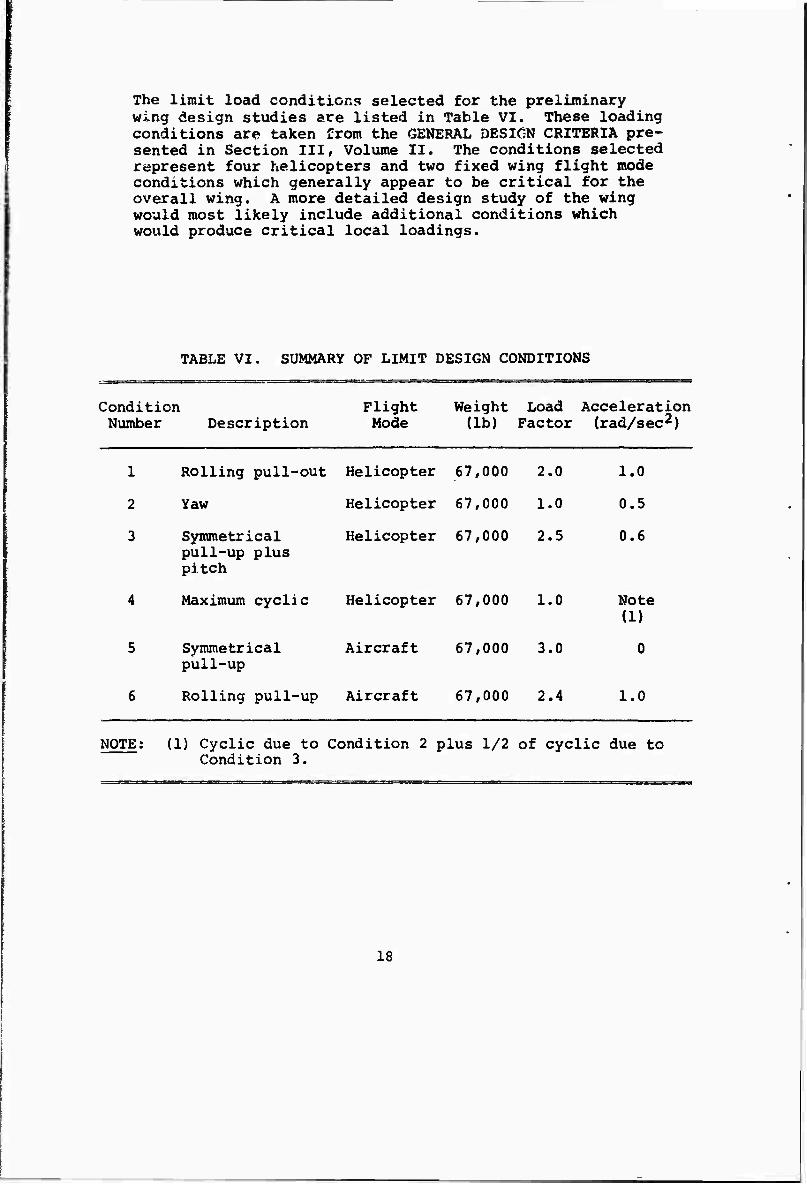
The limit load conditions selected for the preliminary wing design studies are listed in Table VI. These loading conditions are taken from the GENERAL DESIGN CRITERIA pre- sented in Section III, Volume II. The conditions selected represent four helicopters and two fixed wing flight mode conditions which generally appear to be critical for the overall wing. A more detailed design study of the wing would most likely include additional conditions which would produce critical local loadings.
TABLE VI. SUMMARY OF LIMIT DESIGN CONDITIONS
Condition Number Description
Flight Weight Load Acceleration Mode (lb) Factor (rad/sec2)
1
2
3
Rolling pull-out Helicopter 67,000
Yaw Helicopter 67,000
Symmetrical pull-up plus pitch
Helicopter 67,000
Maximum cyclic Helicopter 67,000
2.0 1.0
1.0 0.5
2.5 0.6
1.0 Note (1)
Symmetrical pull-up
Aircraft 67,000 3.0
Rolling pull-up Aircraft 67,000 2.4 1.0
NOTE; (1) Cyclic due to Condition 2 plus 1/2 of cyclic due to Condition 3.
18
3. LOADS
The bending moment, shears and torques imposed on the wing by the loading conditions enumerated in Paragraph 2. are shown on Figures 3 through 10. These curves represent the net results of inertia loads combined with either rotor hub loads or wing airloads. The reference axis for wing torsions has been chosen as a spanwise line connecting the 40 percent chord stations at any wing station.
For any given helicopter flight mode condition, the hub forces are calculated on the basis that the maneuv3r is performed by inducing rotor blade tip path defle wion with cyclic pitch alone and not by a combination of cyclic plus nacelle tilt. The assumption of this method of maneuvering the aircraft produces conservative wing torsional loads and has little or no effect on other loads. In computing the hub forces required to produce a particular maneuver, the in-plane force is computed by assuming a blade tip path deflection in the direction of the force vector. The in-plane force is accompanied by an induced hub moment for which the phase angle is unknown. This phase angle is approximated by assuming 100 percent of the induced moment to act in a sense to produce a wing moment which is addi- tive to that wing moment produced by the in-plane force. In addition, one-third of the induced hub moment is assumed to act in a sense to produce a wing moment acting at 90 degrees to the wing moment produced by the rotor in-plane force.
Rotor hub moments are calculated on the basis of the hinge- less rotor blade with an assumed flapping angle equal to the cyclic angle. Hub torques are based on the power required for any particular loading.
During flight in the helicopter mode all of the lift is provided by the rotor and is applied at the tip of the wing and for flight in the aircraft mode the lift is applied to the wing in a conventional manner. The masses of the fuel and wing structure are divided into concentrated masses inboard and outboard of the cruise fan nacelles and applied at their respective centers of gravity. The fan and rotor nacelle are handled as separate concentrated items of mass.
Table VII presents a summary of the critical wing loadings and the wing areas in which they govern the wing strength.
19
in (N
C5 2 H J M Q
UZ H a
u #% U X u <o %*. O O w
II « w • CU u cu • D W
2 •- H W
U) 2 M OS H W CO u W o
SO 2 O ÜCO M OH ^ u z 2
£ EH O 2 H z 3 5fi o S «
u OO sen
z u *^>, -^-^
W ww
CO
ULTIMATE SHFAR (LB x 10"4) *© «» is
T T T
( ox x ai--Ni) NOISHOJ. aivwiiin
o in in
c e 0*0
■H c ■P a -* 0 ■0 Oi ß OC UO
O 4J % «o r«
vo ß 0 ß
•H 0 m -H »^ +» 0 id fri ^ •
0) — •0 r-td ß 0) u ftj u a>
o w a» «SV
4J •0 ßH «J Vr-i (Z
0 Sm % •
OUH •» 9
u t~t m <a p* 2 0) rH x: NO« W 2
rH 0) 00 IQ ■p . o (Ü O-H g •P •H •• U +1 ß 0) rH 0> D •H
■P 0» U •H O OTJ • +J ßfO O O « U •
1 -P +) OJX; H P en •H «•H EH S <u
1 ■HS •Ö +J fl) H (0
g D (0 -' o
+» U WHO
ro
0) H 3
•A EM
(OT x ai-'Ni) JiNawow DNiaNaa laaA QNY aaoHD aiwuna
20
(Q OT x ai-'Ni) NOISHOL aivwiiin * ' KO ««< CM O
o o ■>»
W u
« ^ 4J Orf di ^ii H U 0 to o u Ü 3 «< ■H rH *- z rH &
0) Sr-* •
(0^ C 0 4J
•H -H x: 4J O»
M ^ -H C <U 0)
o o> s o •H n (0 I7> (0
h tn to 0 • 0 EH rH »H
0 r0 •• ^^ c c to w (0 0 03 m •H C X to +J 3 v ■4J-H 0 & co eu H 0) c s,*' e 0 0 z 0 u 0
a 0 o 0) » H a» -u 1^ O EH o < CM EH
+J (0 «> ns E g-H Tl
to •H+J c 4J rH (0
O rH D Z D^-^. H
0 >H 4J C —
S 0 « -HtN
1 -P 0 4J -rH <U H -0 W ■H C\ £-• 0 -0
1 U (0 o -0 05 o 0) « cH S (U in
0 -0 t^ ■P 0 • w S 0
W — 02 • <:o "* ^ H W EH 0) w u u D< V
Si^ Oi
■H fe
(9_OT x ai- Nl) iwawow DNiaNaa aivwiiin
21
o
< pa x
dN» o
o -o
2 O M
z w
o u z o H to
u H
W
in
< a to
s\ o X u
^1
1 -T- n
-T- T H
o z
o • o
Ü z
w e«
•0 ß c o «
"O id c x u
CN
•d w
4) 4J m ar^ 0 • oo
•H r-4 (0
QJ ^ sen
cu c
(0 •H^l M id a <o u y U'M z WS +J H 0) M
£ (Ü o z to > •
*-* o o <1) CK-P H +Jinx; ^J id • 9
^ •H (1) w -P s D C
0 i-l-H 0 -M
o. to 0 u
C CO
■P 0 « I 0-0
+> u a 0) 0 ■p A id eo
_ -H O » P o 0 H % P Dr-
in
•H
i T3 d)
0)
(. ox x ai) H^aHS aiwiiin
22
ULTIMATE SHEAR (LB x 10~4)
fi
o -lO
•Htn r»
e • 0 n •H 10 k •• o c
fr» 0 •W
o •0 ** o C-H n d'O
c * 0
■p Ü (3 OJ « i +> |g-
•H-^ -•UX MHO «J D 4J « W-H £ 0. wn^
o (U CN o •POO M «O-H «)
S4J W
^•0-0
DO« u
U A 0 * • +1 0) O CO «on
1 S 3 4J H H M A •H 0) EH -PrH
O 1 0,(0 O T3 0 0 i-l 0) O-H
^•H 4J 0^ U 4J O 1' CO s >
SEL
AG
E
AC
TIO
N)
•
0)
EM § M
•^
(9_OT x ai-'Ni) iNawoii DNicmaa aivwixin
23

0)0)" 4J »o « to c u e 3 »? •HO«
o ß
C \o 0) 0 -P
•H " C •MO« •rt-H S »o >-< o cos O >i Ü u +» (0
(0 c o
g i
•H X
05
O 3
0) 0)
•H
. ^ •
OTM H o u 0)
(A H I-* —v
0) +» 13 (0 g
•H •P
M 0 .
■P in S ' OS rH I
■P H •• •H C EH O
1 -H TJ P Q) -H
O fi 4J O
0) ■H tf»
P» ß • Oo
■H 0) 0}
-p ta ü o tr-H
•H P u <u >
in
w U ü H
0) M 3 tj>
■1-1
b
(01 x ai-'Ni) NOISHOI aivwiiin
24
L OT x ffi) avaHS aiwixin o
JL
CM I
(9_OT x g-i-'Ni) XNawow ONiaNaa IYDIIHHA axvwij.in
25
01
00
(U M 3 en M
m « n ■p 0 1 M
-H ■P 10 H-O D c <W^ a
0 m o« G O 00 •H O +.' % ■H r- TJ SO C 0 % o M
z ■p 1« 0^
in ß • • 0-«*^v
■H 0) (0 •^« U CU-H o D a ti 1 M
f-l Ü «HO
■p 3rH
1 Oi U
■H H^s •P « + •-I o — D •rl
u m M P-H 0 0) •P g ß 0 6 0 « >i-H
1 w to -P M H .. 0 •H BFH f 0
1 •H ^ •O P P 0) •H J- a -o tn 0 fi-H p 0 0) w U S
(Ti
VI
■H
ro <N I
( OT x ST-'NI) NOISHOi aiVWIilQ
26
00
I I
ULTIMATE SHEAR (LB X 10"4)
o « 00 CM r-i
I
T—T T T T T
«0Ä 6 01
-H -H ■M V
D •>—' 01 ^^
«Cl vo O U
H 0) cow o ^> •H M "0
CO«n O th •
«.o «w « O O •0 •«- Or- C S «o O
+» « U 0)
0) »
H O 0.«
Q) u o 0« <
C G ■H -H M
O 4JH r-l OOO 12! Öä « I
4J
I
0)
n .. 3 CH 0 CU
- -H 2
O ßoo +» O •
0)
( ox x ai-"ND iNawow aivwio/in
27
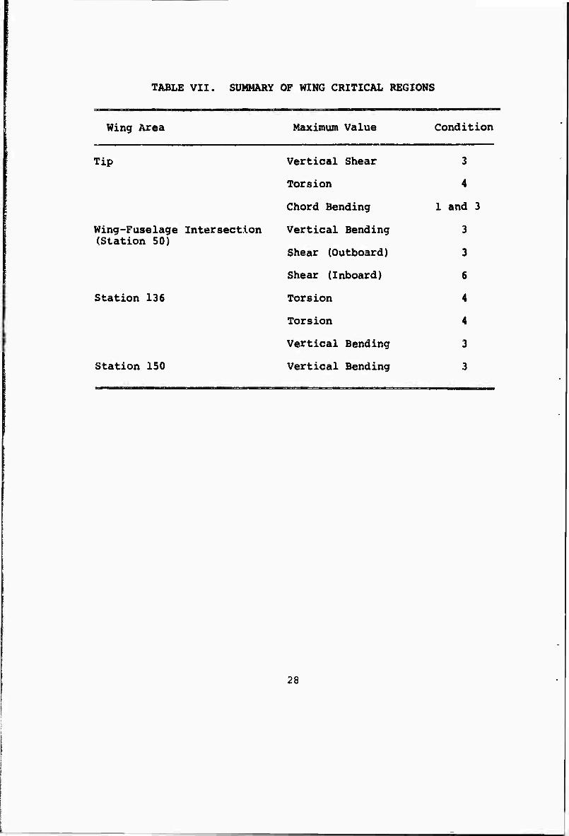
TABLE VII. SUMMARY OF WING CRITICAL REGIONS
Wing Area Maximum Value Condition
Tip Vertical Shear 3
Torsion 4
Chord Bending I and 3
Wing-Fuselage Intersection (Station 50)
Vertical Bending
Shear (Outboard)
3
3
Shear (Inboard) 6
Station 136 Torsion 4
Torsion 4
Vertical Bending 3
Station 150 Vertical Bending 3
28
4. DESIGN
a. Wing Design Philosophy
The approach taken to the design of the stowed-tilt- rotor wing is to concentrate on the determination of what the critical design conditions cure and to use a conventional wing design in order to make these deter- minations with the greatest speed and assurance of accuracy. Use of conventional design permitted these determinations to be made using conventional methods of analysis and eliminated the possibility of becoming bogged down with new and unusual designs requiring new methods of analysis based on less reliable materials analysis. Once the critical wing design envelope has been established, studies will be made to see what weight advantages can be obtained by designing with some of the newer composite materials. A fallout of this approach is that it has been determined that a useful vehicle can be obtained using conventional materials and design. Volume I, Sections XIII and XIV of this interim report discusses the weight advantages which are thought to be possible with the use of ad- vanced materials and design.
The following procedure was used in order to arrive at a wing structural box design that would meet all of the load requirements:
(1) Examine the existing helicopter and fixed wing structural requirements and select those design conditions which produced critical wing loadings. (See paragraphs 2 and 3 of this section.)
(2) Design a wing with components sized to meet the ultimate strength requirements of the critical design conditions determined in (1) above.
(3) Determine the torsional, normal and chordwise stiffness of the ultimate strength wing and examine the forced response of the wing structure under the excitation of the rotor loads.
(4) Prepare a cyclic loading spectrum for the wing to include load inputs due to rotor operation in addi- tion to the normal air and ground load inputs.
(5) Evaluate the wing stiffness and fatigue strength resulting from ultimate strength design and provide local strength increases or material substitutions as required to provide a wing which will meet all of the strength, stiffness and fatigue requirements,
29
b. Description of Wing
(1) Planforro, Taper and Thickness
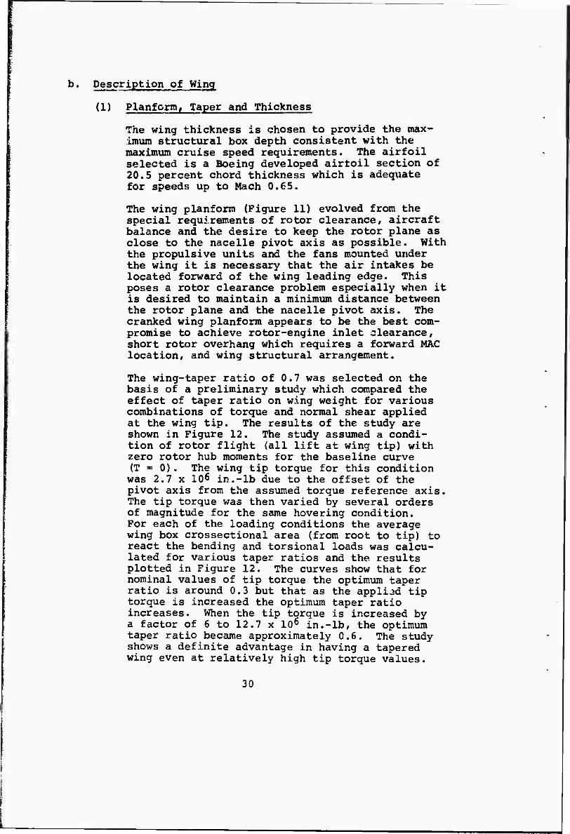
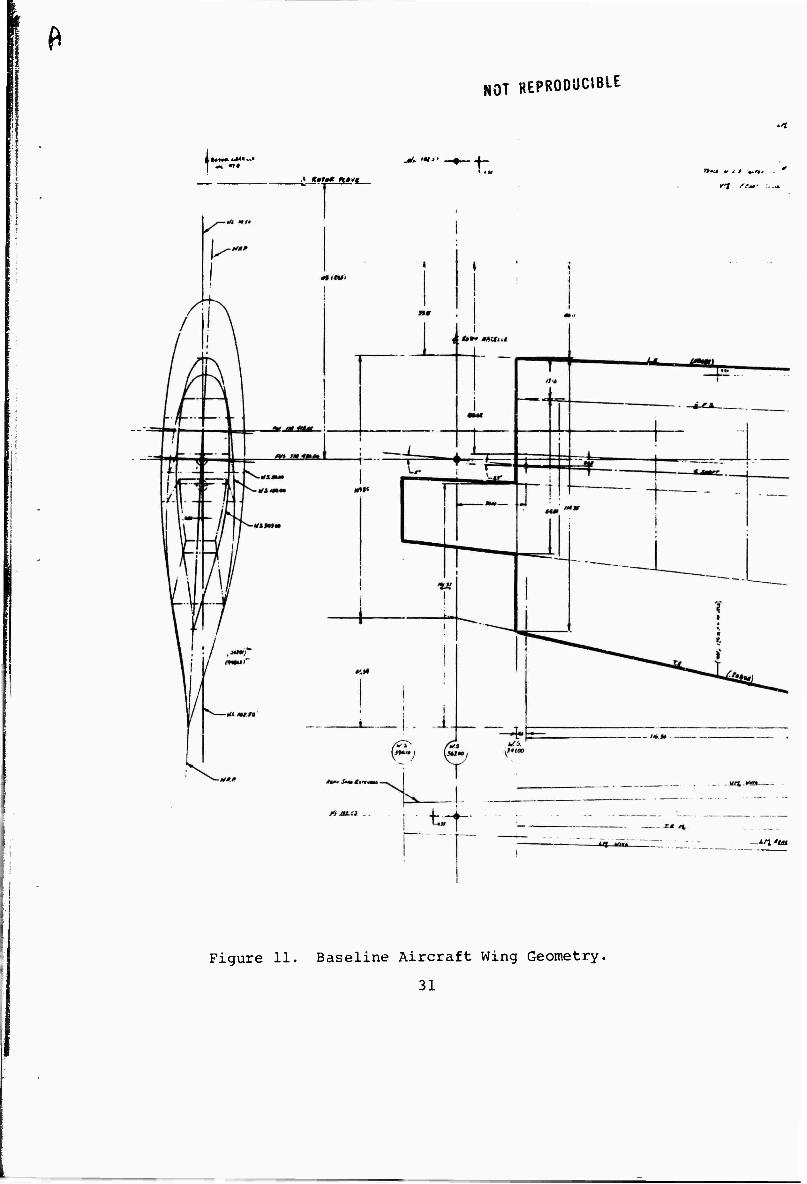
The wing thickness is chosen to provide the max- imum structural box depth consistent with the maximum cruise speed requirements. The airfoil selected is a Boeing developed airtoil section of 20.5 percent chord thickness which is adequate for speeds up to Mach 0.65.
The wing planform (Figure 11) evolved from the special requirements of rotor clearance, aircraft balance and the desire to keep the rotor plane as close to the nacelle pivot axis as possible. With the propulsive units and the fans mounted under the wing it is necessary that the air intakes be located forward of the wing leading edge. This poses a rotor clearance problem especially when it is desired to maintain a minimum distance between the rotor plane and the nacelle pivot axis. The cranked wing planform appears to be the best com- promise to achieve rotor-engine inlet clearance, short rotor overhang which requires a forward MAC location, and wing structural arrangement.
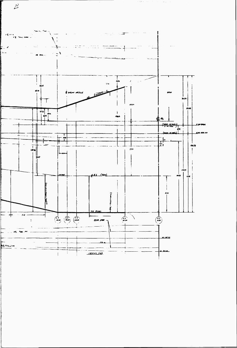
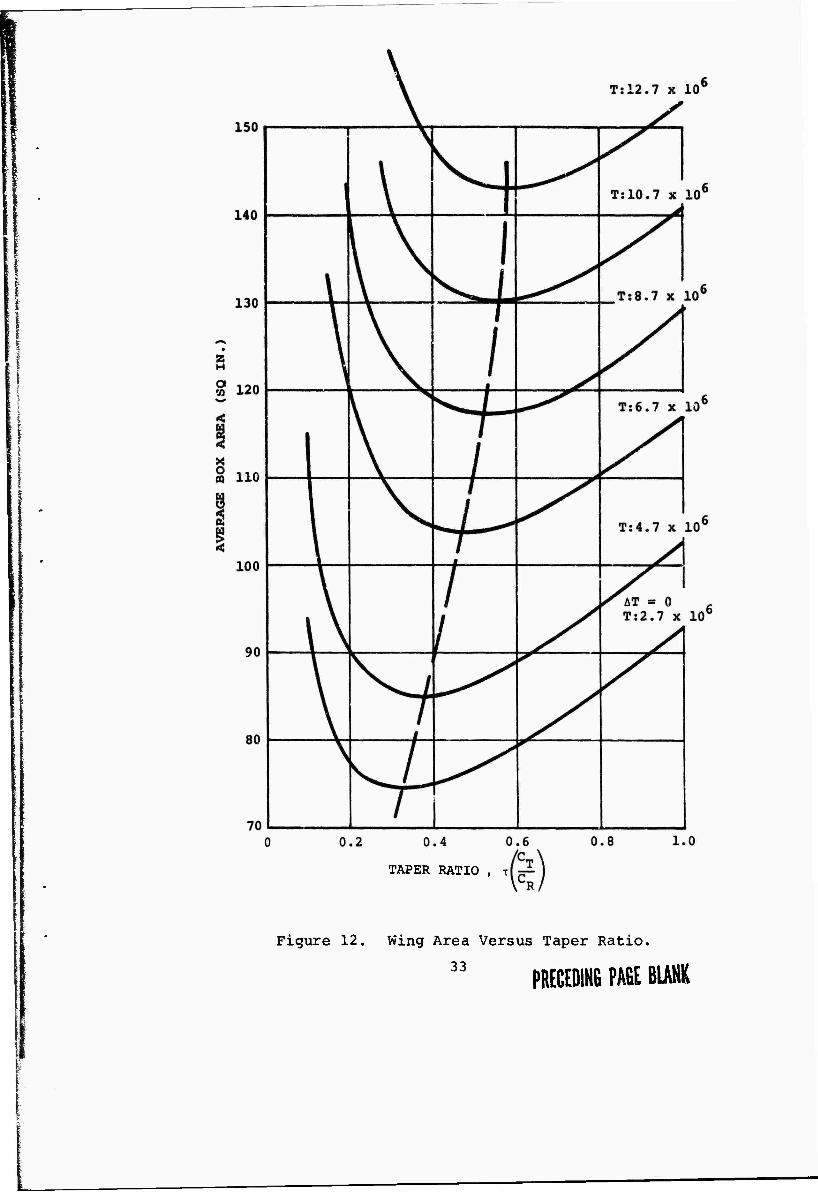
The wing-taper ratio of 0.7 was selected on the basis of a preliminary study which compared the effect of taper ratio on wing weight for various combinations of torque and normal shear applied at the wing tip. The results of the study are shown in Figure 12. The study assumed a condi- tion of rotor flight (all lift at wing tip) with zero rotor hub moments for the baseline curve (T = 0). The wing tip torque for this condition was 2.7 x 106 in.-lb due to the offset of the pivot axis from the assumed torque reference axis. The tip torque was then varied by several orders of magnitude for the same hovering condition. For each of the loading conditions the average wing box crossectional area (from root to tip) to react the bending and torsional loads was calcu- lated for various taper ratios and the results plotted in Figure 12. The curves show that for nominal values of tip torque the optimum taper ratio is around 0.3 but that as the applied tip torque is increased the optimum taper ratio increases. When the tip torque is increased by a factor of 6 to 12.7 x 106 in.-lb, the optimum taper ratio became approximately 0.6. The study shows a definite advantage in having a tapered wing even at relatively high tip torque values.
30
NOT REPRODUCIBLE
jL. •«" —+-
.1 gtwg »H»VC t.
itl'ist
Figure 11. Baseline Aircraft Wing Geometry.
31
£
*t —I i 1 fäixt -AM
r.'
äJfIMM
ttl*o em* &* V \
»I '»* ■
0.00 l
r—■ - LOO cm t. tfi.
Kt ft"
TAPER RATIO , T
Figure 12. Wing Area Versus Taper Ratio.
33 PRECEDING PAGE BLANK
The other consideration to be evaluated in connec- tion with taper ratio is the cross-sectional area required at the tip to permit passage of the power t.:ansniission system. Based on preliminary esti- mates of the bevel box size, a minimum taper ratio of 0.7 is indicated. The taper ratio chosen is therefore based on the tip cross-section require« ments but is very close to the optimum ratio for minimum overall wing weight.
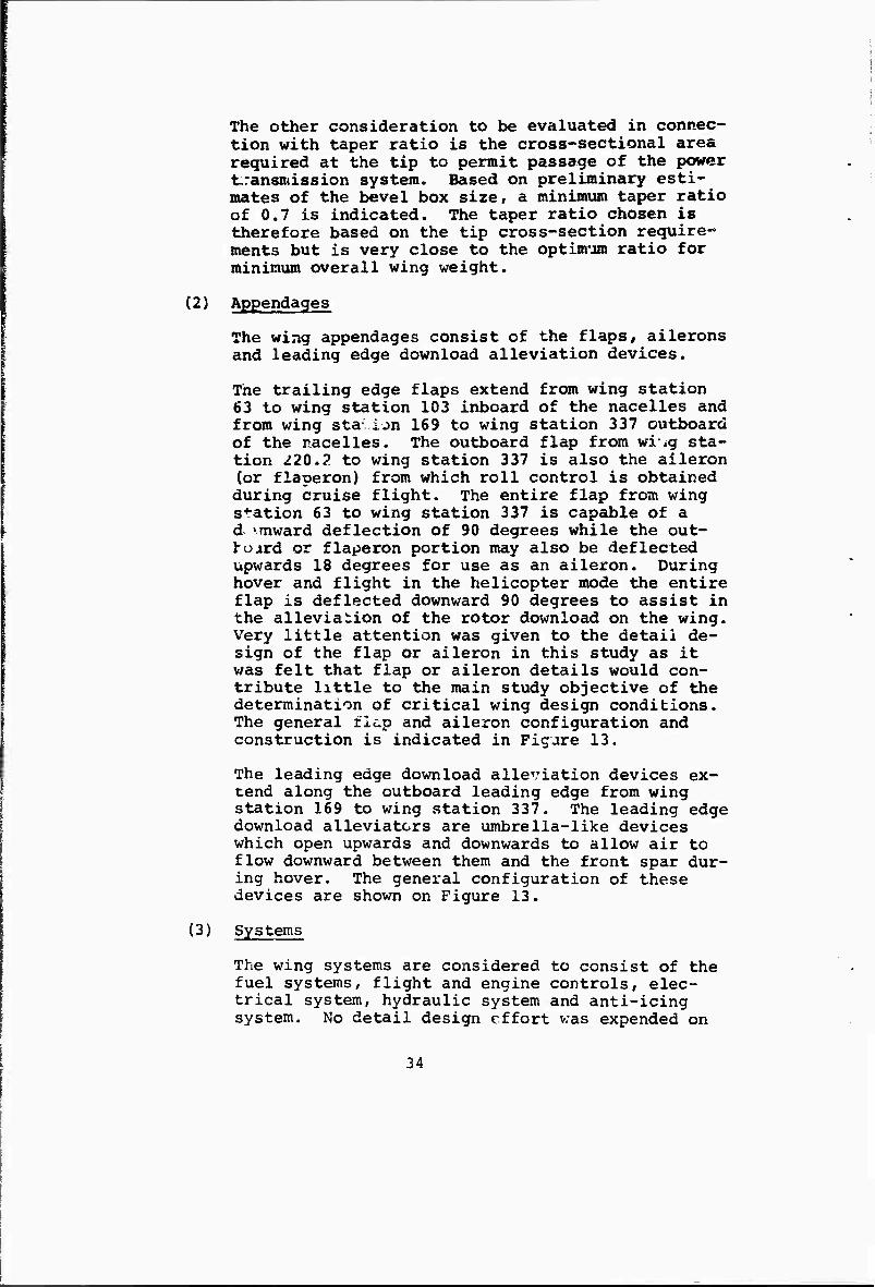
(2) Appendages
The wing appendages consist of the flaps, ailerons and leading edge download alleviation devices.
The trailing edge flaps extend from wing station 63 to wing station 103 inboard of the nacelles and from wing sta ijn 169 to wing station 337 outboard of the nacelles. The outboard flap from wi ig sta- tion 220,2 to wing station 337 is also the aileron (or flaperon) from which roll control is obtained during cruise flight. The entire flap from wing station 63 to wing station 337 is capable of a d 'mward deflection of 90 degrees while the out- hojird or flaperon portion may also be deflected upwards 18 degrees for use as an aileron. During hover and flight in the helicopter mode the entire flap is deflected downward 90 degrees to assist in the alleviation of the rotor download on the wing. Very little attention was given to the detail de- sign of the flap or aileron in this study as it was felt that flap or aileron details would con- tribute little to the main study objective of the determination of critical wing design conditions. The general flip and aileron configuration and construction is indicated in Figure 13.
The leading edge download alleviation devices ex- tend along the outboard leading edge from wing station 169 to wing station 337. The leading edge download alleviators are umbrella-like devices which open upwards and downwards to allow air to flow downward between them and the front spar dur- ing hover. The general configuration of these devices are shown on Figure 13.
(3) Systems
The wing systems are considered to consist of the fuel systems, flight and engine controls, elec- trical system, hydraulic system and anti-icing system. No detail design effort was expended on
34
•a
G O
•M ■P o 3 W 4J (0 c o u
a
o a
id M O u •H
4) C •H
© (0
CQ
n
0) M 3
•H fa
35
the wing systems during this study as effort spent in this direction would add little to the obtaining of the design objectives. Considera- tion was given to reserving space in the wing for the installation of all systems. Weight allow- ances have been included in the wing inertia relief estimates for all the above systems.
The fuel system weight and space allocation assumes self-sealing tanks with armor protection on six sides plus an inert gas purging system. All of the engine and flight controls are con- tained in an integrated fly-by-wire flight control system; hence, the only hydromechanical systems contained in the wing are those used to convert the computer outputs into mechanical power to actuate the control surfaces and engine controls. All of the hydraulic and/or electrical lines are routed through one of three areas of the wing; forward of the front spar; aft of the rear spar; or in the transmission box area between the A and B spars. Power actuators for the flaps and flaperons will be located aft of the rear spar under the fixed trailing edge and the leading edge download alleviator actuators will be located in the leading edge forward of the front spar.
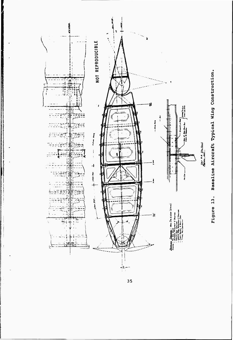
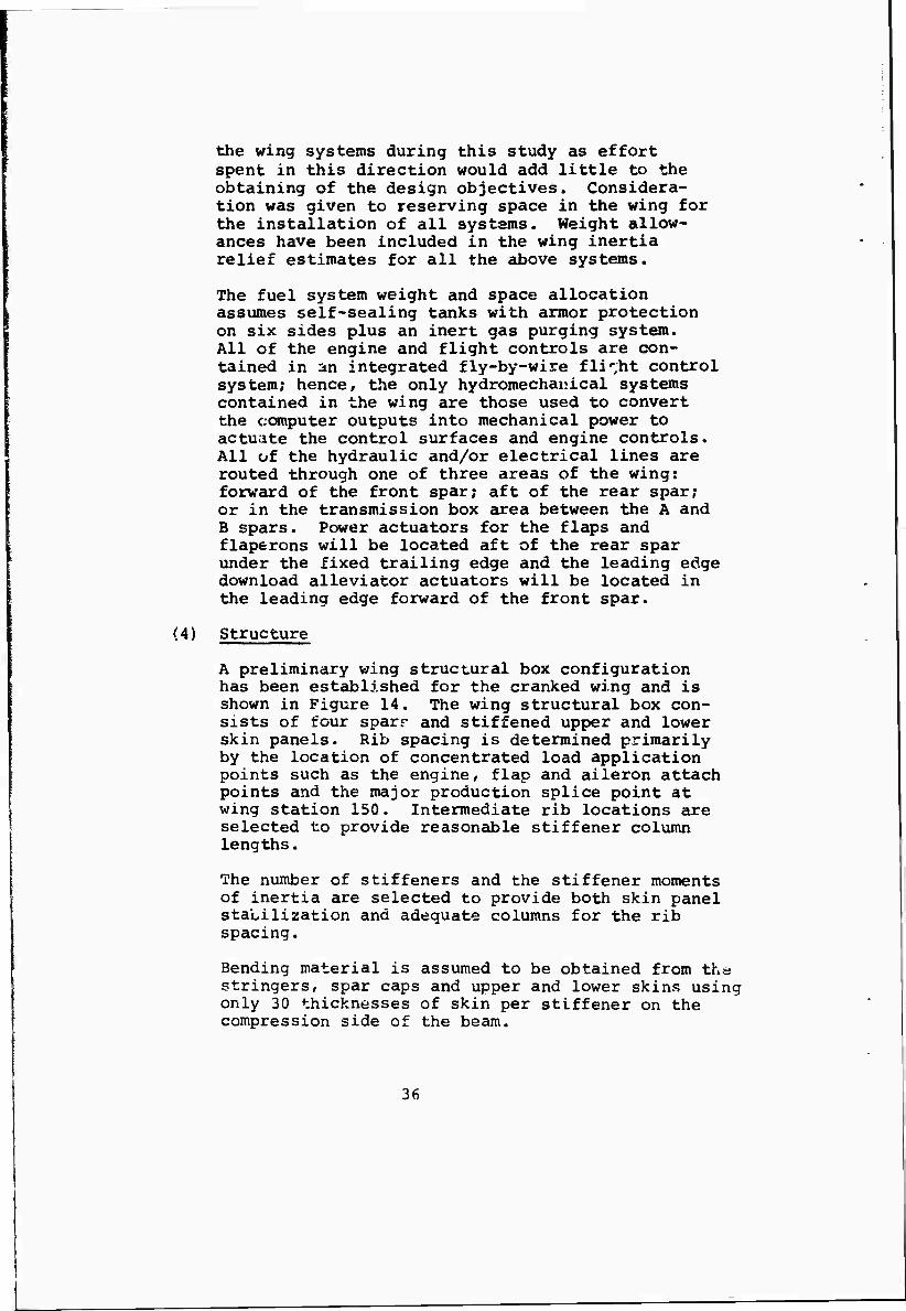
(4) Structure
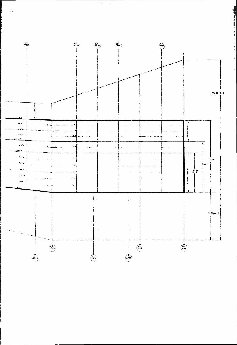
A preliminary wing structural box configuration has been established for the cranked wing and is shown in Figure 14. The wing structural box con- sists of four sparr and stiffened upper and lower skin panels. Rib spacing is determined primarily by the location of concentrated load application points such as the engine, flap and aileron attach points and the major production splice point at wing station 150. Intermediate rib locations are selected to provide reasonable stiffener column lengths.
The number of stiffeners and the stiffener moments of inertia are selected to provide both skin panel stabilization and adequate columns for the rib spacing.
Bending material is assumed to be obtained from the stringers, spar caps and upper and lower skins using only 30 thicknesses of skin per stiffener on the compression side of the beam.
36
p
^ Q« ■^
^
Figure 14. Baseline Aircraft Structural Box Geometry.
?7
'9* 33 far)
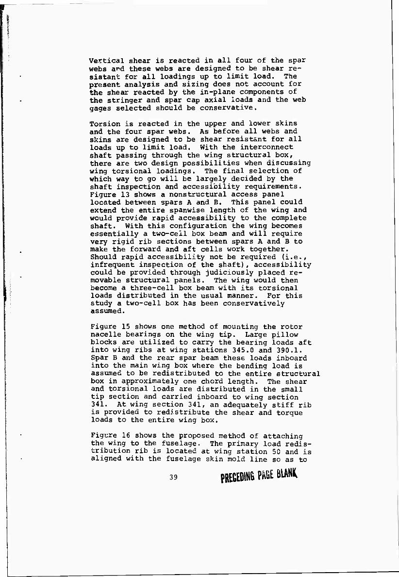
Vertical shear is reacted in all four of the spar webs a^d these webs are designed to be shear re- sistant for all loadings up to limit load. The present analysis and sizing does not account for the shear reacted by the in-plane components of the stringer and spar cap axial loads and the web gages selected should be conservative.
Torsion is reacted in the upper and lower skins and the four spar webs. As before all webs and skins are designed to be shear resist&nt for all loads up to limit load. With the interconnect shaft passing through the wing structural box, there are two design possibilities when discussing wing torsional loadings. The final selection of which way to go will be largely decided by the shaft inspection and accessibility requirements. Figure 13 shows a nonstructural access panel located between spars A and B. This panel could extend the entire spanwise length of the wing and would provide rapid accessibility to the complete shaft. With this configuration the wing becomes essentially a two-ceil box beam and will require very rigid rib sections between spars A and B to make the forward and aft cells work together. Should rapid accessibility not be required (i.e., infrequent inspection of the shaft), accessibility could be provided through judiciously placed re- movable structural panels. The wing would then become a three-cell box beam with its torsional loads distributed in the usual manner. For this study a two-cell box has been conservatively assumed.
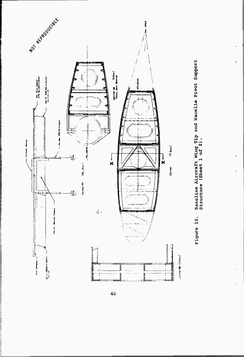
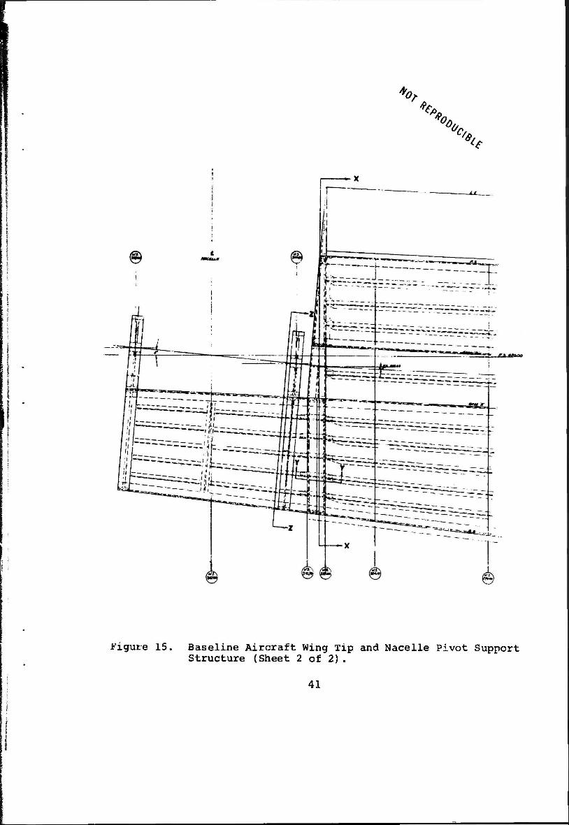
Figure 15 shows one method of mounting the rotor nacelle bearings on the wing tip. Large pillow blocks are utilized to carry the bearing loads aft into wing ribs at wing stations 345.0 and 390.1. Spar B and the rear spar beam these loads inboard into the main wing box where the bending load is assumed to be redistributed to the entire structural box in approximately one chord length. The shear and torsional loads are distributed in the small tip section and carried inboard to wing section 341. At wing section 341, an adequately stiff rib is provided to redistribute the shear and torque loads to the entire wing box.
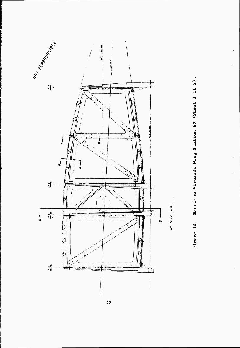
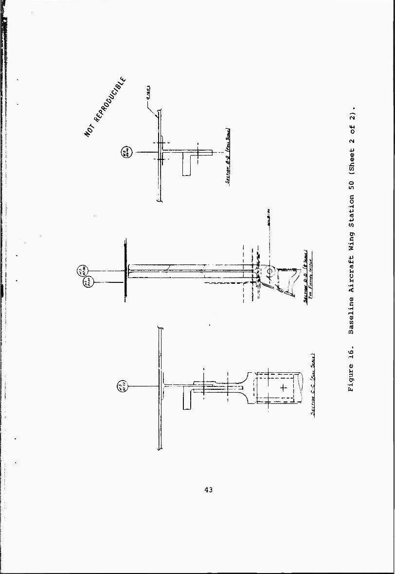
Figure 16 shows the proposed method of attaching the wing to the fuselage. The primary load redis- tribution rib is located at wing station 50 and is aligned with the fuselage skin mold line so as to
39 PREGEDIHS mi BIAHIC
^
^
^
u a §• en v
•rl 04
0)
V Ü id
•0 n w 0.
•1-1 • EH ^^
(N 0» CM-l
•H 0 £
i-l •P «H 4J (0 0» U 0) ü J3 M (A
•H ^ta-* <
0) 0) M c 3
•H -P r-1 Ü 0) 3 in M nJ +» m w
in
0)
I •H
40
vo, ^
%, 'CA 6. <e
Figure 15. Baseline Aircraft Wing Tip and Nacelle Pivot Support Structure (Sheet 2 of 2).
41
/
^
51
o a
O
o in
g «0 +» w tr C5
•H m ■p «W nj M Ü U
<
•H H (Ü (0 (0 Ö
^P
M
42
#
! s
\
i \ i
K
"F
ZL
IM O
(N
0) 0)
o in
e o
•H +> (0 +» tn
o> c
•H S +> M-l
<T3 U U
•H < 0) c
•H
^-T ^
o u
k 1
a) (0
03
VO
0)
•H
43
eliminate any eccentricities in the transfer of chordwise shear into the fuselage. This shear connection with the fuselage is made as light and flexible as possible to accommodate the wing flex- ure relative to the fuselage. The vertical shear is transferred directly from each of the wing spar webs to the fuselage frames through eight fittings (four on each side of the fuselage) and eight bolts. The bolts are orientated in a longitudinal direction (chordwise) to eliminate the transfer of moment to the fuselage frames from wing flexure. The use of fittings on each spar web reduces the shear lag in the wing root, and, therefore, reduces the loads in the root rib at wing station 50; at the same time, the use of eight fittings provides a fail-safe wing to fuselage joint. If the detail analysis indicates a need for it, the use of split fittings would also increase the fail-safety of the design.
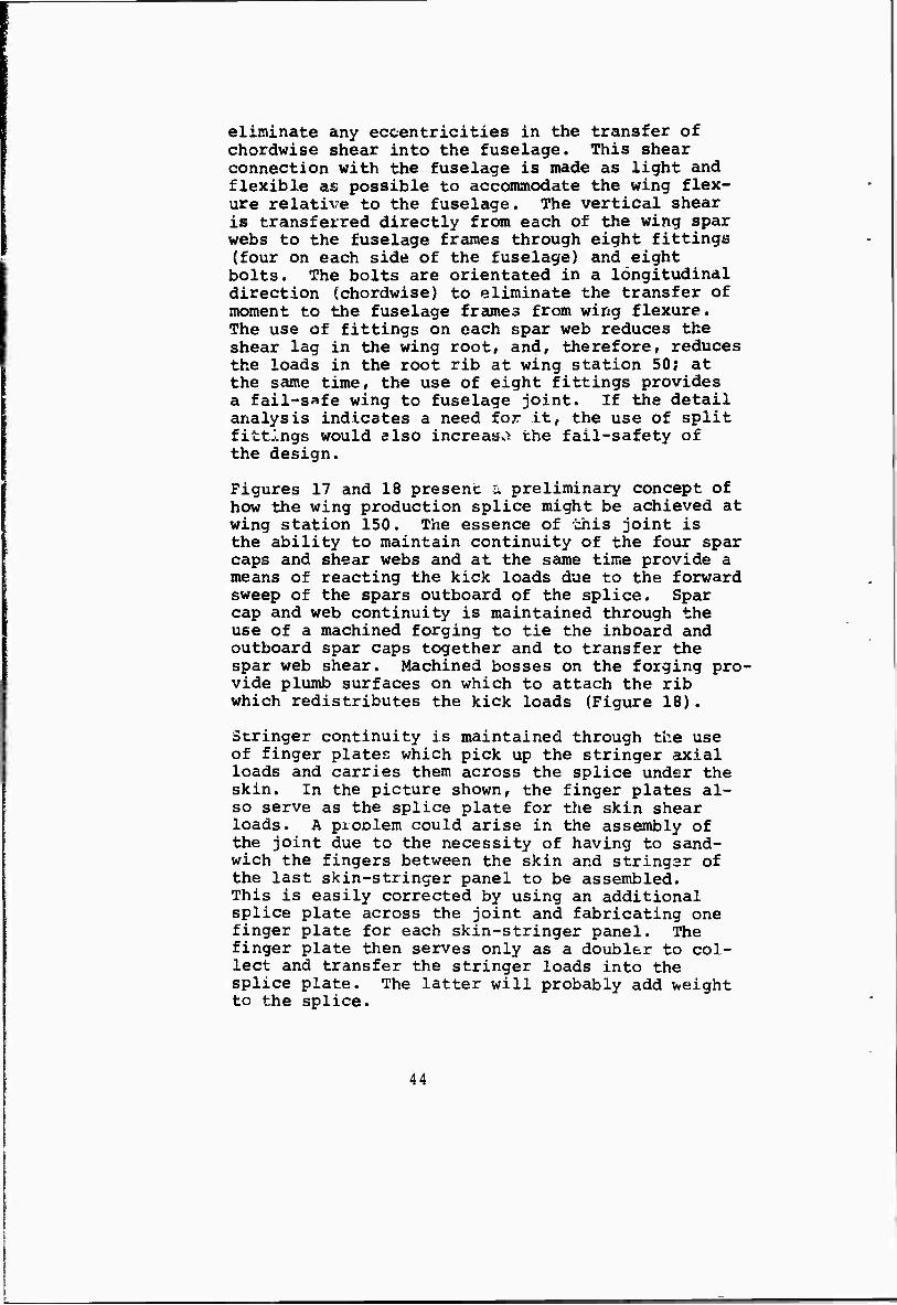
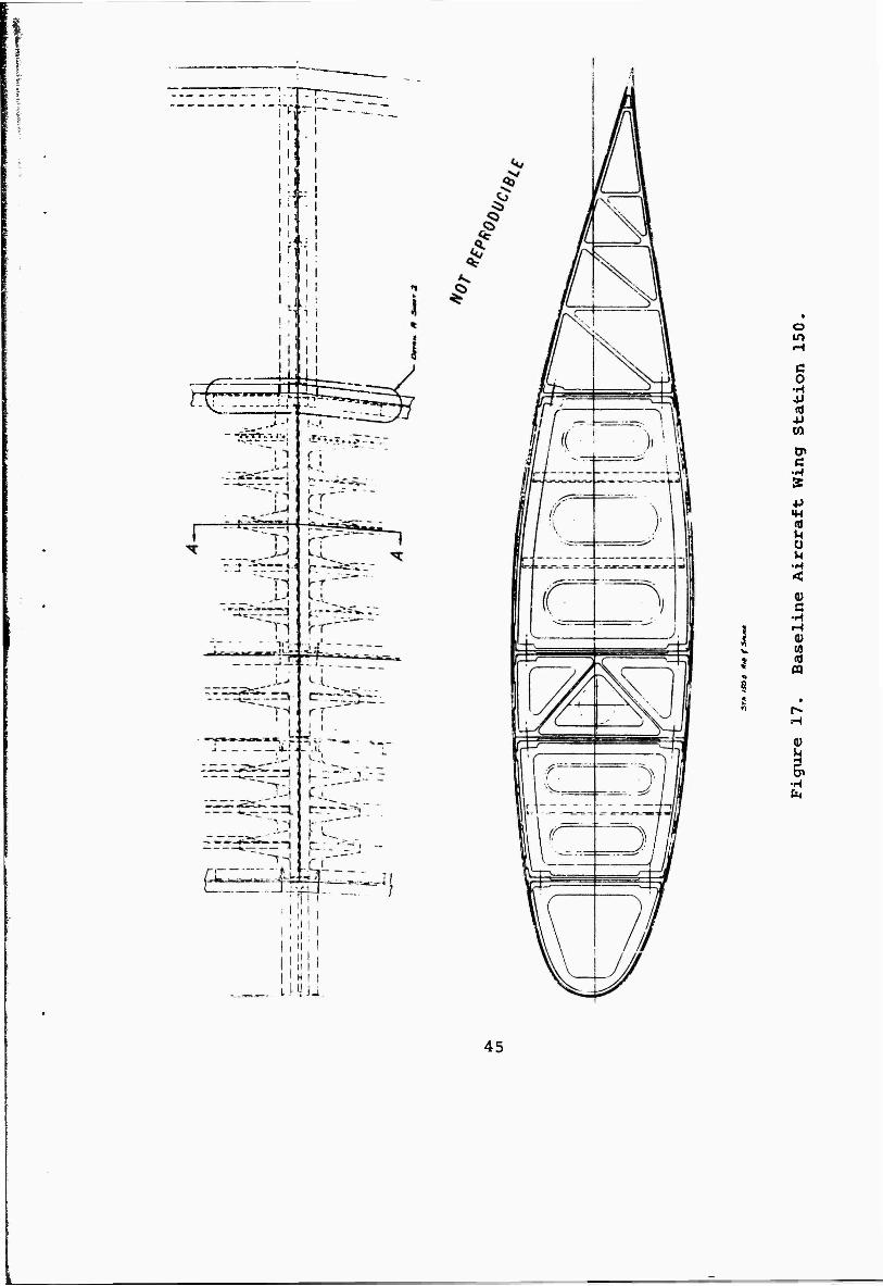
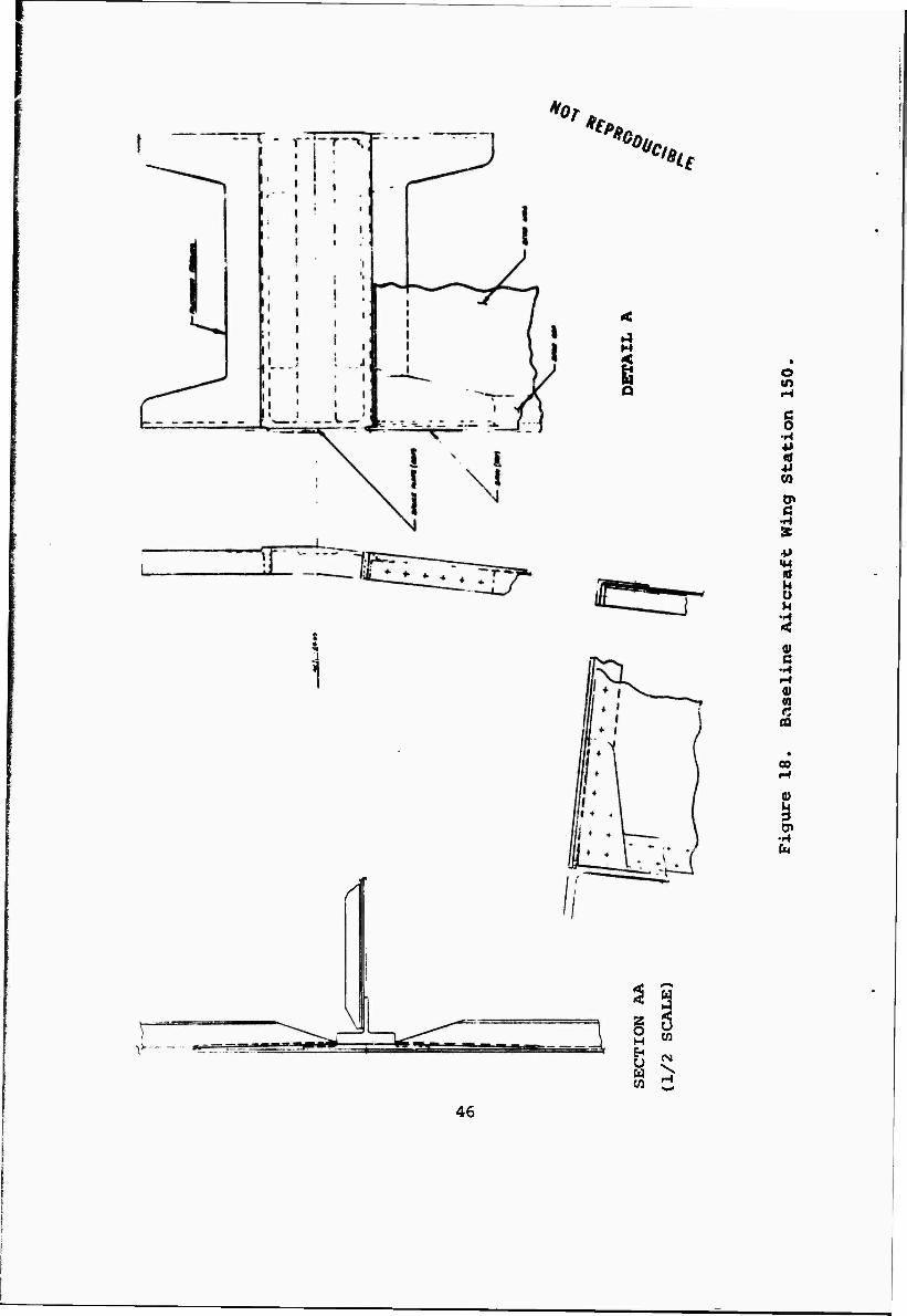
Figures 17 and 18 present ü preliminary concept of how the wing production splice might be achieved at wing station 150. The essence of this joint is the ability to maintain continuity of the four spar caps and shear webs and at the same time provide a means of reacting the kick loads due to the forward sweep of the spars outboard of the splice. Spar cap and web continuity is maintained through the use of a machined forging to tie the inboard and outboard spar caps together and to transfer the spar web shear. Machined bosses on the forging pro- vide plumb surfaces on which to attach the rib which redistributes the kick loads (Figure 18).
Stringer continuity is maintained through the use of finger plates which pick up the stringer axial loads and carries them across the splice under the skin. In the picture shown, the finger plates al- so serve as the splice plate for the skin shear loads. A problem could arise in the assembly of the joint due to the necessity of having to sand- wich the fingers between the skin and stringer of the last skin-stringer panel to be assembled. This is easily corrected by using an additional splice plate across the joint and fabricating one finger plate for each skin-stringer panel. The finger plate then serves only as a doubler to col- lect and transfer the stringer loads into the splice plate. The latter will probably add weight to the splice.
44
I
V
_ .j- - -rvrv..
O m
ß 0
•H jj «Ö •P CO
tn
2 u M
<
s •H H 0) 03 «J
fa
45
r
*or
'
*&, HQQ "ClB,
H
s
o m H
§ •H ■P «a +• (0
en c
IM « M O U
t I H « 0)
(0
oo
•rt fa
46
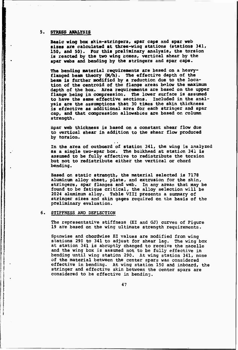
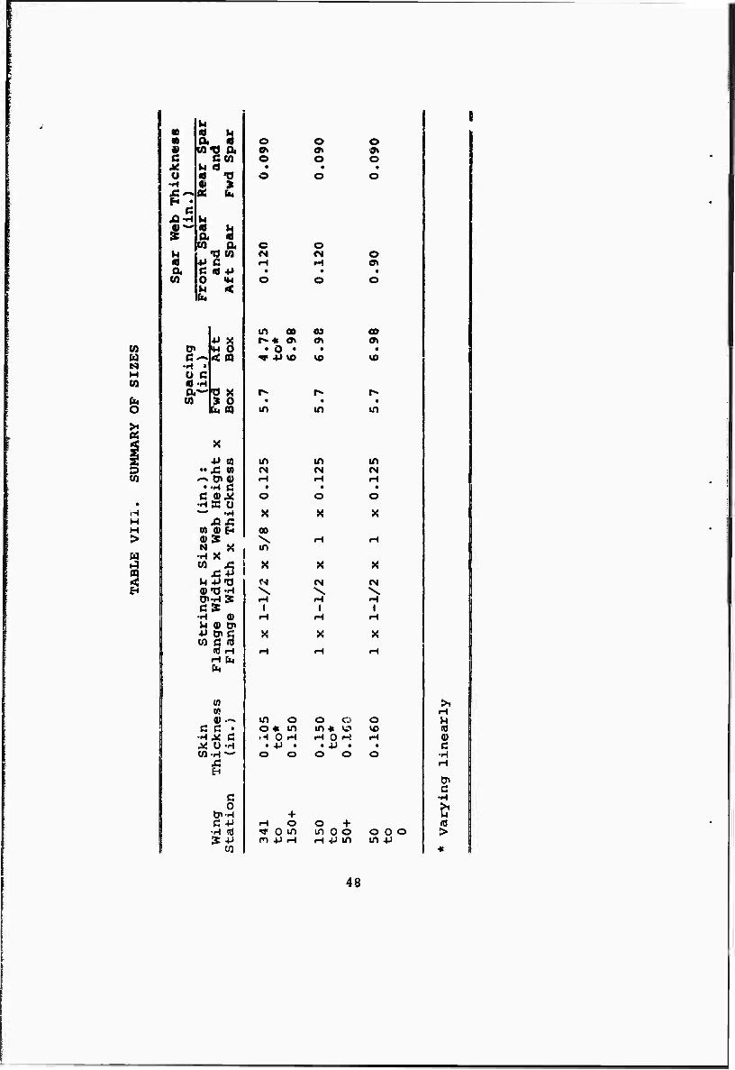
5. STRESS AMELYSIS
Basic wing box skin-stringers, spar caps and spar web sizes axe calculated at three-wing stations (stations 341» 150« and 50). For this preliminary analysis, the torsion is reacted by the two wing icoxes, vertical shear by the spar webs and bending by the stringers and spar caps.
The bending material requirements are based on a heavy- flanged beam theory {M/h). The effective depth of the beam is further modified by a reduction due to the loca- tion of the centroid of the flange areas bolow the maximum depth of the box. Area requirements are based on the upper flange being in compression. The lower surface is assumed to have the same effective sections. Included in the anal- ysis are the assumptions that 30 times the skin thickness is effective as additional area for each stringer and spar cap» and that compression allowables are based on column strength.
Spar web thickness is based on a constant shear flow due to vertical shear in addition to the shear flow produced by torsion.
In the area of outboard of station 341, the wing is analyzed as a single two-spar box. The bulkhead at station 341 is assumed to be fully effective to redistribute the torsion but not to redistribute either the vertical or chord bending.
Based on static strength, the material selected is 7178 aluminum alloy sheet, plate, and extrusion for the skin, stringers, spar flanges and web. In any areas that may be found to be fatigue critical, the alloy selection will be 2024 aluminum alloy. Table VIII presents a summary of stringer sizes and skin gages required on the basis of the pre1iminary evaluation.
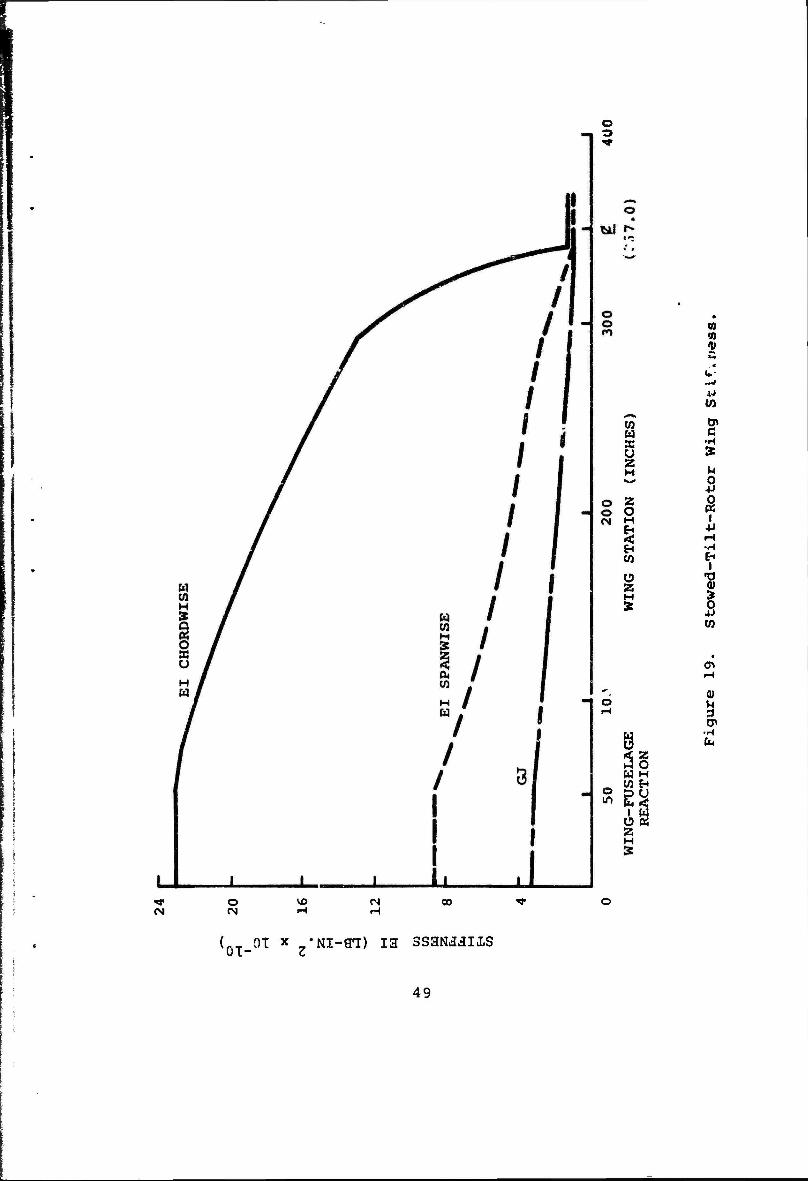
6. STIFFNESS AND DEFLECTION
The 19 are
representative stiffness (El and GJ) curves of Figure re based on the wing ultimate strength requirements.
Sp&nwise and chordwise El values are modified from wing stations 290 to 341 to adjust for shear lag. The wing box at station 341 is abruptly changed to receive the nacelle and the wing box is assumed not to be fully effective in bending until wing station 290. At wing station 341, none of the material between the center spars was considered effective in bending. At wing station 150 and inboard, the stringer and effective skin between the center spars are considered to be effective in bending.
47
•9 « « C M O •H
H • G
JQ-M
I" « a w
14
Oi 8 wo cu cm « -o
U « n a 2 co a
•o CO *> c C « 4J O «M U <
•H » Ü c «t-H
(0
H
W
n
4J ffl "X « ,-. 0»flj
••H ß C (UJ4 •HÄ O —' -H
01 fl) H Q» S N X
•H X
H -P-O
o o
o OH o
o o
c O M «N O H M a*
m 0 km 4.7
5
to*
6
.98
•
\a x • m
• in
u +»
0)
QnC c 3 (0 rH H fa fa
(0 n
c ß • •H^ ß
d o
c +J
St +» CO
H
00 \ m
\ I
m CM r-l
* o
X
00
in
in fM
o X
CN \
I
X
H
m o o * m H 0 H
. 4J . O O
+ H O ^ 0 m n 4J H
o o in « w fH o H
• +J • o o
o
o + in 0 o r-t +J in
o 0 o in +J
u Q 0) ß •H
0> c
-H >1 M (0 >
48
m
o
I
w w SB
M
2 O H
z H
w w c
■H
5 «
•H
I
cn
*-- 0) d r-) ä
CP
Ö äg W H
^ W H
s e^ 1 K u 2 z
•«1" O CM
VO CM 03
(0-_0T x -Nl-ffl) 13 SSaNJJII.S
49
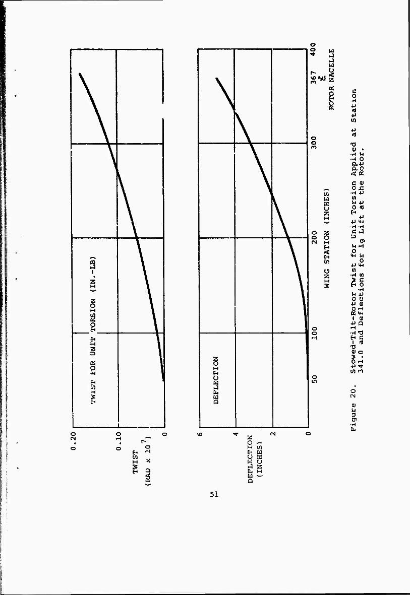
The GJ curve is based on the stiffness of the forward and aft boxes and the section between the center parts is assumed to be ineffective in torsion.
Figure 20 contains a plot of twist due to a unit torsion applied at wing station 341 and deflection of the wing due to a lg lift condition in the helicopter configuration. Stiffness assumptions are the same as discussed u>ove,
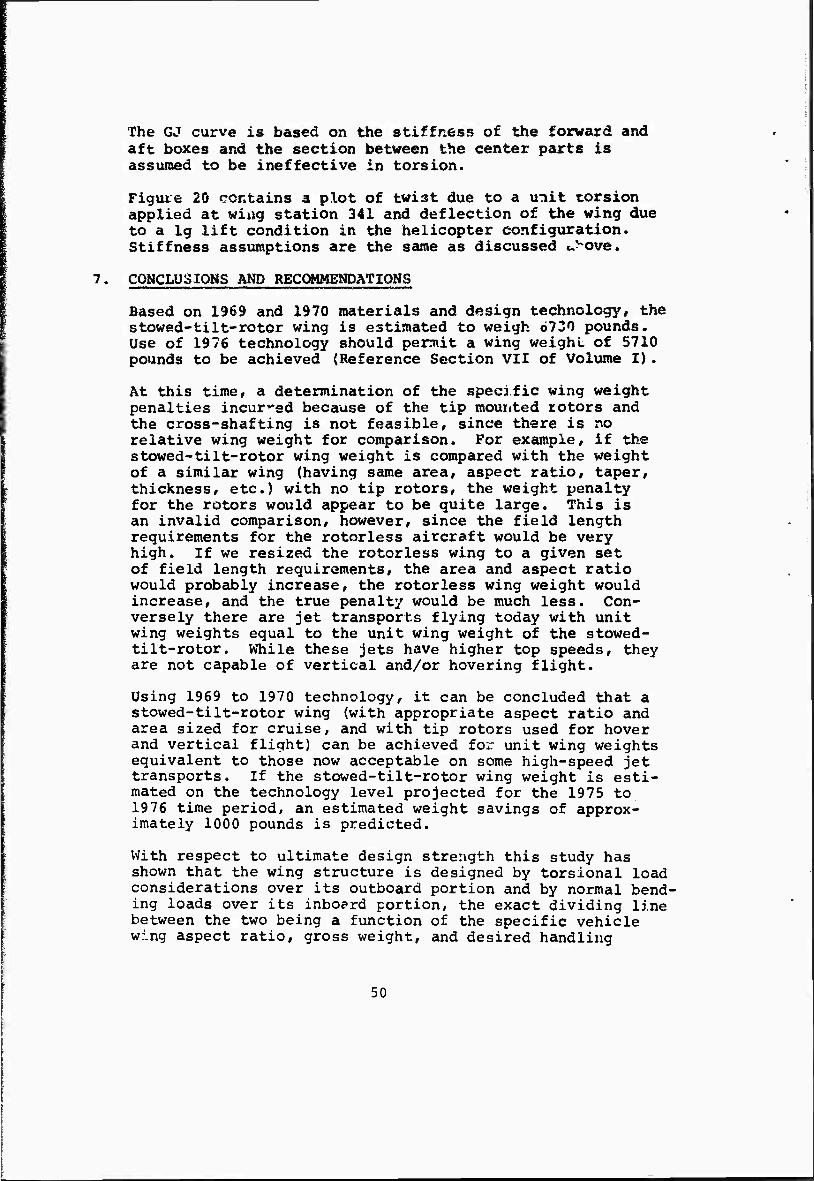
7. CONCLUSIONS AND RECOMMENDATIONS
Based on 1969 and 1970 materials and design technology, the stowed-tilt-rotor wing is estimated to weigh 6730 pounds. Use of 1976 technology should permit a wing weighL of 5710 pounds to be achieved (Reference Section VII of Volume I).
At this time, a determination of the specific wing weight penalties incurred because of the tip mounted rotors and the cross-shafting is not feasible, since there is no relative wing weight for comparison. For example, if the stowed-tilt-rotor wing weight is compared with the weight of a similar wing (having same area, aspect ratio, taper, thickness, etc.) with no tip rotors, the weight penalty for the rotors would appear to be quite large. This is an invalid comparison, however, since the field length requirements for the rotorless aircraft would be very high. If we resized the rotorless wing to a given set of field length requirements, the area and aspect ratio would probably increase, the rotorless wing weight would increase, and the true penalty would be much less. Con- versely there are jet transports flying today with unit wing weights equal to the unit wing weight of the stowed- tilt-rotor. While these jets have higher top speeds, they are not capable of vertical and/or hovering flight.
Using 1969 to 1970 technology, it can be concluded that a stowed-tilt-rotor wing (with appropriate aspect ratio and area sized for cruise, and with tip rotors used for hover and vertical flight) can be achieved for unit wing weights equivalent to those now acceptable on some high-speed jet transports. If the stowed-tilt-rotor wing weight is esti- mated on the technology level projected for the 1975 to 1976 time period, an estimated weight savings of approx- imately 1000 pounds is predicted.
With respect to ultimate design strength this study has shown that the wing structure is designed by torsional load considerations over its outboard portion and by normal bend- ing loads over its inboard portion, the exact dividing line between the two being a function of the specific vehicle wing aspect ratio, gross weight, and desired handling
50
If
I
' \
\
\
\
3 •
H
§ H
a \
H
« o fa
1 '
\
^
\
\
§ H
U u a CM w
o 2 w
H
o o
o o
w o 55
o H
<
a 2 H S
o o
o in
o vo
w H S EH
o H
X
Q
2 O — H W H W u a w u a 2 fa H w — Q
(N
c o
-H
«5
•0
-^ M rH 0
ao
c o
-H tfl
0 H 4J
C D
U 0
0)
■H
IP
N 0
4J U-l (0
•H tß
^g •H
^ 4J 0 Ü 4J 0) OH 05 «w
1 0) ■P Q H •-CO H C
I IT) Tl 0) O ? • OH
w n
o CM
(U M 3 cn
•A fa
51
qualities. The wing presented in this report utilizes similar skin stringer construction over its entire length - the only concession to the predominance of torsion or bend- ing being made in skin thickness, stringer moment of inertias, and spar shear webs. The number of stringers L« constant throughout the span but their moment-, of inertia and area is altered as required to permit proper column action (bending restraint) or to provide adequate skin shear panel stabilizations. Further design studies should be performed to determine what, if any, weight savings could be achieved by using completely different design concepts o" the inboard and outboard portions of the wing - the outboard design being optimum foi. torque and the inboard being optimum for bending.
The results of preliminary investigation into the dynamic behavior of the w.' g are presented in Section IX (of Volume I), STRUCTURAL uYNAMICS ANALYSIS. The analyses indicate that the ultimate strength wing design is stable and free of flutter throughout its anticipated operating rai«ge. The work in the preliminary investigation is based on the wing parameters developed during the study, and pre- sented in this section. These parameters are obtained through the use of preliminary type estimates (i.e., as- sumed deep beam theory, minimum number of stations analyzed, neglect of in-plane forces due to taper, neglect of princi- pal axis, etc.) and it is most likely that the indicated structure could be refined to reduce the weight of the wing with little or no change in the stiffness properties. The greatest change in stiffness properties would probably result from the use of advanced materials such as the boron and carbon filament composites. Use of these materials shows promise of increasing the rigidity of the structure and it should be possible to provide a wing from these materials which is also dynamically adequate for tip- mounted tilting rotors.
Preliminary evaluation of the wing with respect to fatigue has not been accomplished. This evaluation should be made when data are obtained which allows a load spectrum to be established. These data are expected to become available with the completion of the wind tunnel testing program planned for Phase II.
The derivation of an accurate load spectrum for this flight mode will involve the establishment of acceptable flight handling characteristics during transition and conversion and a determination of the best means of providing the required control forces during hover and transition in a specified environment.
52
The following additional work is recoaanended for the wing:
a. Initiate studies on the use of advanced composite materials which would utilize their increased strength and stiffness properties to reduce the wing weight and possibly the wing thickness to improve the overall air* craft performance.
b. Initiate studies on the installation of an anti-icing system on the stowed-tilt-rotor aircraft wing leading edge containing the proposed download alleviation devices.
c. Study, in more detail, the means of installing and gaining access to the power transmission system.
d. Initiate design studies on the installation of the wing fuel system, including armor protection and purge sy tems.
e. Initiate design studies on the installation of flap, aileron, and aileron trim actuation systems.
f. Additional design studies of the Interface between the tip pod and the wing to determine a means of predicting the equivalent stiffness of the joint.
53
I
t
,
SECTION V
ROTOR BLADE
1. OBJECTIVES
a. Basic Objectives
(1) To provide a rotor blade which shall completely meet all aircraft operational envelope require- ments and produce the required thrust within the rotor and transmission power lim: ts for the full period of the blade's intended design life.
(2) In addition, the rotor blade shall accomplish this task without compromising the safety or perform- ance of the aircraft under any operating condi- tions, including folding, and must be free from any resonances and vibratory coupling with any other portions of the aircraft structure through- out its entire speed envelope, from stopping to overspeed.
(3) The rotor blade shall be capable of producing a thrust margin of 15 percent over the normal thrust (including download) at any mission hover condi- tion of weight, altitude, and temperature before reaching the stall flutter condition.
(4) The rotor blade shall be designed with local structural reinforcement provisions for blade clamps applied during folding, and shall possess additional structural provisions, as required, to tolerate repeated nesting into the nacelle recesses.
(5) The rotor blade shwill operate with reasonabla stress levels, and possess acceptable dynamic response characteristics.
(6) The rotor blade shall be designed so that the planned construction and manufacturing methods are within the state-of-the-art projected for the mid-igvo's.
'o. Detc.il Objectives
(1) To provide design flexibility for adjustment of vibration characteristics, thereby permitting
55 MCCEDINS PAGE BUINK
i i
tuning vibration frequencies to be within an acceptable tolerance of predicted frequenciesf with only minor modifications of the blade design.
(2) To be removed and installsä (or replaced) without disturbing the pitch control system.
(3) To provide vernier pitch adjustments of the blade for tracking purposes.
(4) To include support for root-end aerodynamic cuff fairings and folding fairings.
(5) To maintain adequate clearance with all parts of the aircraft for both in-flight and ground loads.
(6) To be individually interchangeable.
(7) To be immune to damage under normal handling.
(8) To be operable under worldwide environmental con- ditions with provisions for the following:
(a) Substantial elimination of water absorption
(b) Corrosion protection
(c) Rain and sand erosion protection
(d) Deicing
(e) Materials, of themselves and as combined with the other materials used, to be compat- ible with the operating temperature extremes.
2. DESIGN CRITERIA
a. Design Loads
(1) Fatigue Conditions
The fatigue performance of the rotor shall be evaluated for the conditions specified in General Design Criteria. Critical fatigue loads on the rotor blade are produced by cyclic pitch control. For preliminary design, ti^i following cyclic con- dition is considered in the evaluation of the fatigue strength of the rotor blade: rotor cyclic control, in the helicopter mode, equal to the cyclic required to trim the aircraft level plus 25 percent of the maximum cyclic for aircraft pitch or yaw control, whichever is greater.
56
Deaaon^tnation of adequate fatigue strength for this condition is assvuned indicative of the blade fatigue psrformance for the complete fatigue load- ing spectrum.
(2) Limit Load Conditions
The ultimate strength of the rotor blade shall be evaluated for the conditions specified in General Design Criteria. For preliminary design the fol- lowing conditions are to be considered:
(a) Maximum cyclic pitch
(b) 2.5g vertical takeoff
(c) The limit rotor rpm is equal to 1.25 times the normal hover rpm.
b. Blade Natural Frequences
(1) The first three flap-lag coupled natural frequen- cies shall be displaced by at least +10 percent of rotor rpm and 0.15/rev from any integer harmonic at the normal operating rpm for both helicopter flight and airplane flight.
(2) The first lag bending natural frequency ratio at the normal helicopter rpm shall be 0.75 to 0.80.
(3) The first flap bending natural frequency ratio at the normal helicopter rpm shall be 1.2 to 1.25.
(4) The first torsional natural frequency shall be displaced +10 percent of rotor rpm and +25 percent from an integer harmonic.
(5) There shall be no resonance crossings within the normal operating rpm range.
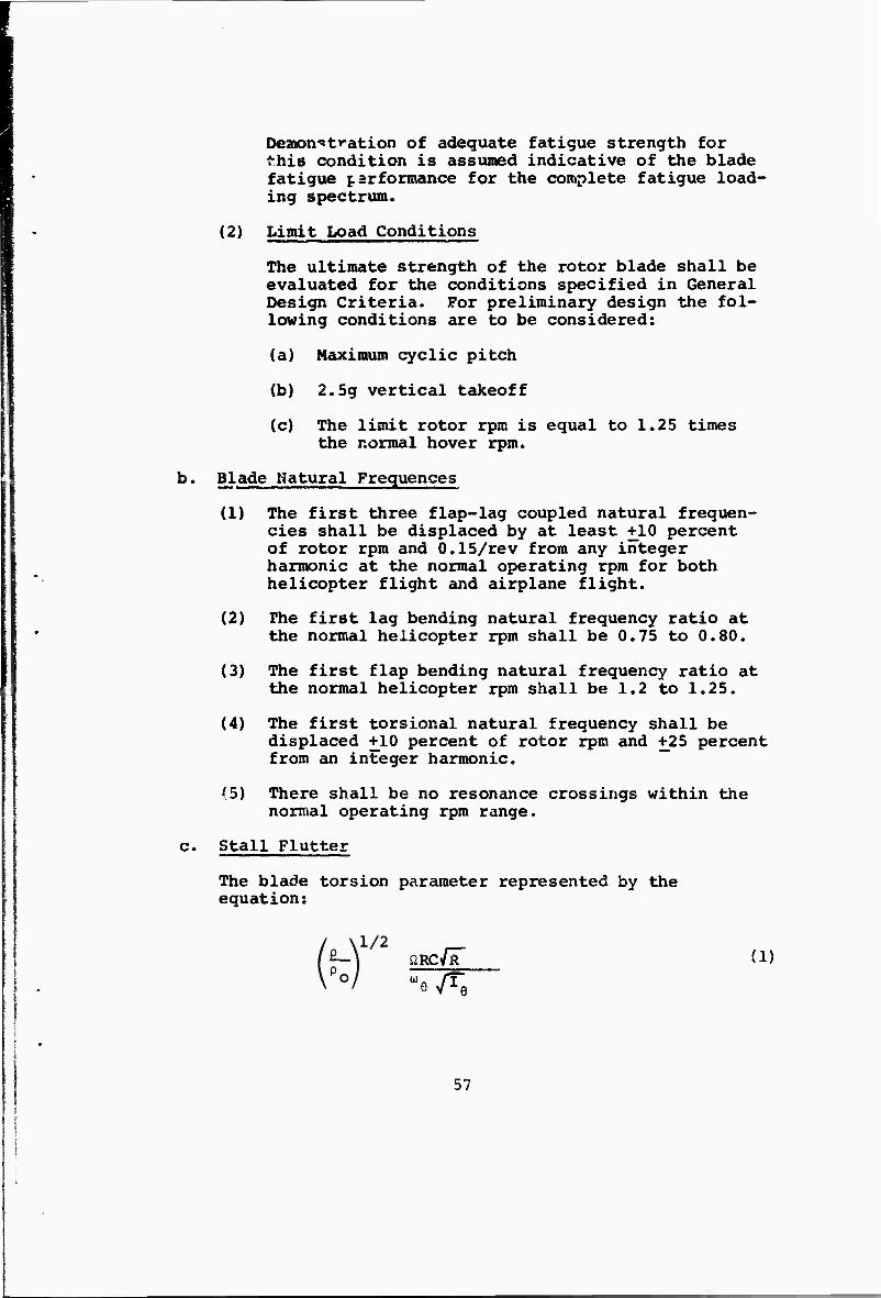
c. Stall Flutter
The blade torsion parameter represented by the equation:
fiRC JR (i) "o/Te
57
where p = air density at altitude, slugs per cubic foot
p - air density at sea level, slugs per cubic 0 foot
Q « rotor angular velocity, radians per second
R - rotor blade radius, feet
C = rotor blade chord, feet
u = first torsional natural frequency, radians per second
_ 2 I = weighted pitch inertia, slugs feet
shall be no greater than 36, The rotor — corresponding to this value equals 0.137.
d. The dynamic balance axis shall be located at 24.5 per- cent chord.
3- DESIGN (See Figure 21)
a. Retention
The retention design is provided in the shape of a double frustrum of a cone with major diameters back to back. Considerable effort was expended to provide a retention design with a minimum blade radius, ir> order to meet the flexural bending criteria of the rotor blade. The result produces the end-of-hub stiffness at 0.1 r/R which is satisfactory from a blade flexure stress standpoint. This design provides the proper shape to react the centrifugal force loads and the moment loads directly into the cuter bearing sleeve. A metallic internal mandrel is invested into the tubu- lar spar root and provides adequate resistance to radial crushing and to out-of-round distortion due to cocking or moment loads. A set of tapered matching shoes are arranged around the outer conic surface of the spar to react all loads due to centrifugal force. A backup semiconic ring is used at the inner end of the spar to preload the spar against the outer ring and take up all radial looseness. A preload nut is in- tended to be torqued up solidly during manufacture and is never removed in the field.
58
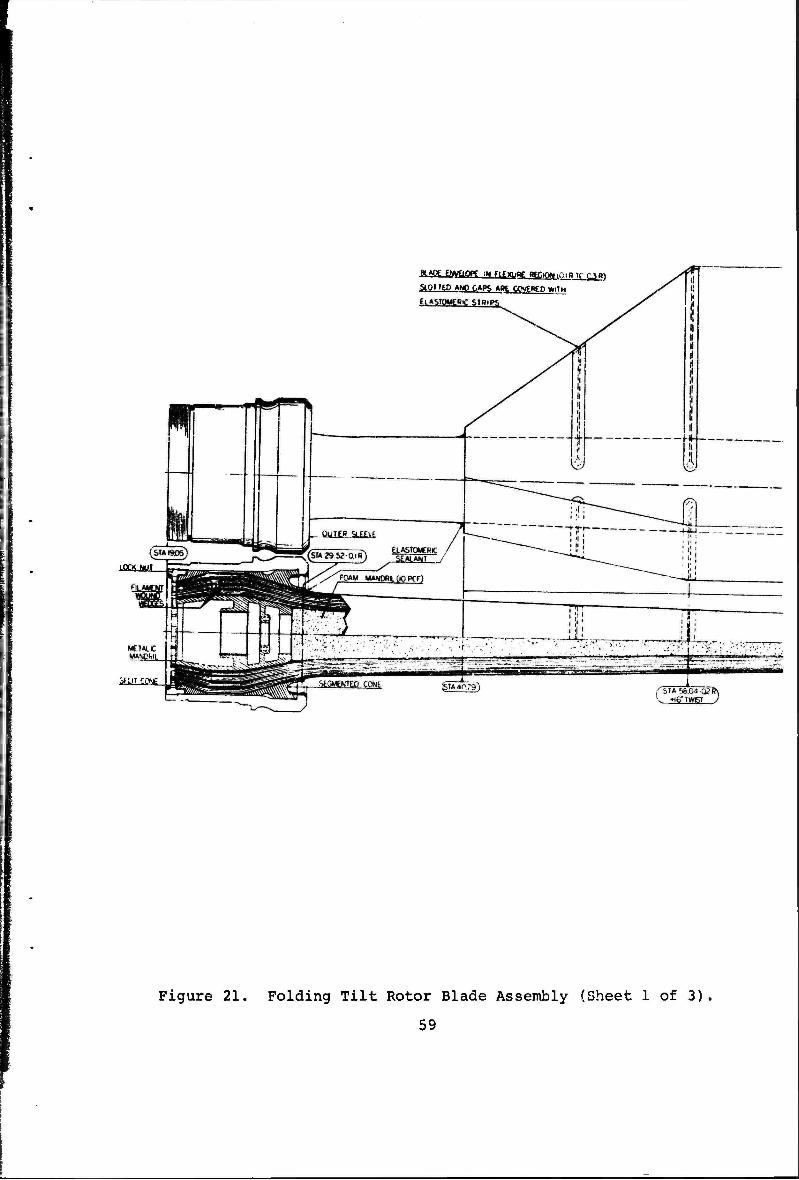
LOCKHUL
3'l" CONE
StOHED *N0 CAPS A»E COVtHEO VWTH
Figure 21. Folding Tilt Rotor Blade Assembly (Sheet 1 of 3).
59
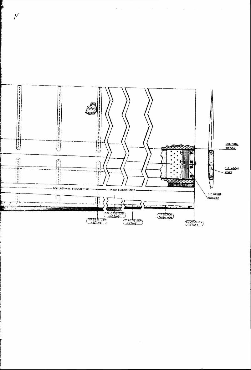
/
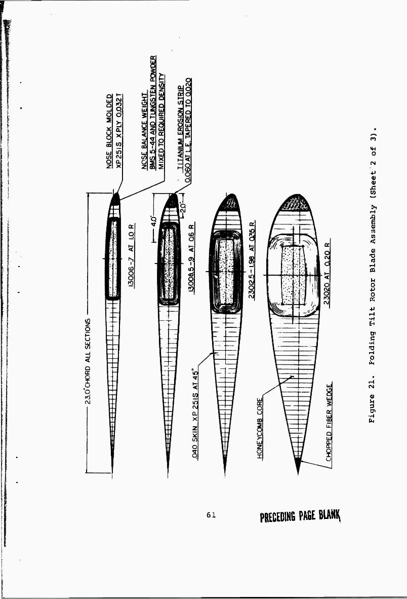
I
■ I
O
(N
■P <u <u x: to
r-l
0) T! (0
rH CQ
2
c •H
o fa
0)
3
•H fa
61 PRECEDlNfi PAfiE BIAMI^
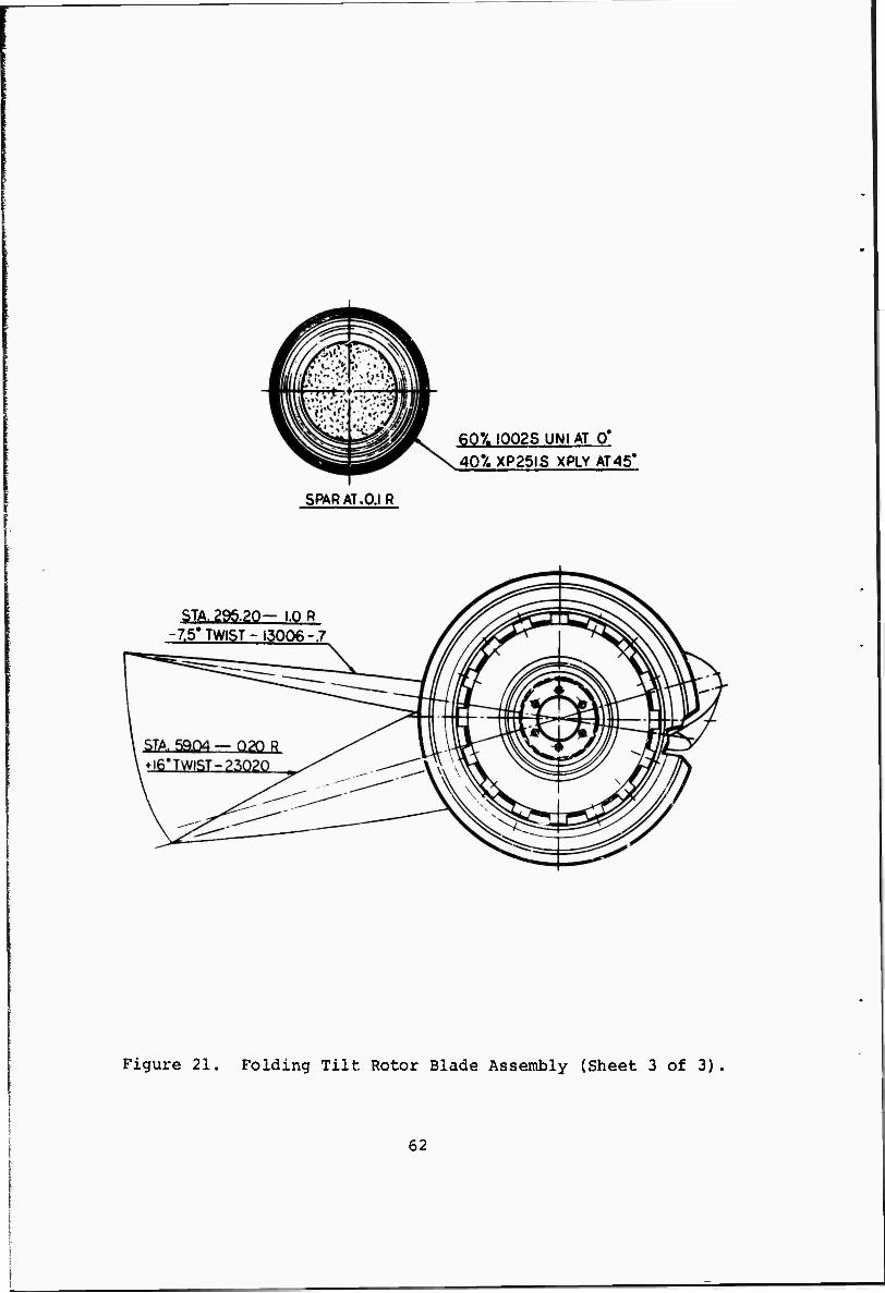
60'/. I002S UNI AT 0* 40% XP25IS XPLY AT45'
SPAR AT.O.I R
STA.29§.20-i.QR ■7.5'TWIST-13006-.7
Figure 21. Folding Tilt Rotor Blade Assembly (Sheet 3 of 3)
62
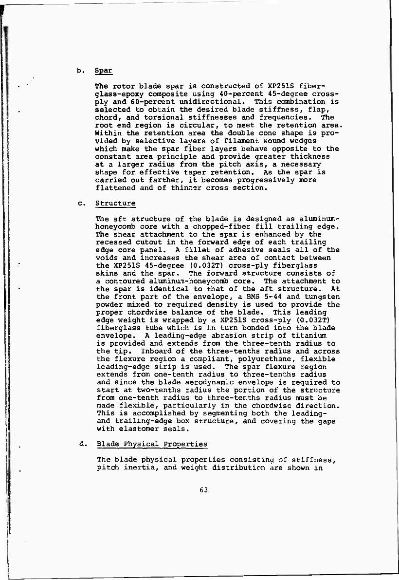
I
b. Spar
The rotor blade spar is constructed of XP251S fiber- class-epoxy composite using 40-percent 45-degree cross- ply and 60-percent unidirectional. This combination is selected to obtain the desired blade stiffness, flap, chord, and torsional stiffnesses and frequencies. The root end region is circular, to meet the retention area. Within the retention area the double cone shape is pro- vided by selective layers of filament wound wedges which make the spar fiber layers behave opposite to the constant area principle and provide greater thickness at a larger radius from the pitch axis, a necessary shape for effective taper retention. As the spar is carried out farther, it becomes progressively more flattened and of thinr.er cross section.
c. Structure
The aft structure of the blade is designed as aluminum- honeycomb core with a chopped-fiber fill trailing edge. The shear attachment to the spar is enhanced by the recessed cutout in the forward edge of each trailing edge core panel. A fillet of adhesive seals all of the voids and increases the shear area of contact between the XP251S 45-degree (0.032T) cross-ply fiberglass skins and the spar. The forward structure consists of a contoured alumimm-honeycomb core. The attachment to the spar is identical to that of the aft structure. At the front part of the envelope, a BMS 5-44 and tungsten powder mixed to required density is used to provide the proper chordwise balance of the blade. This leading edge weight is wrapped by a XP251S cross-ply (0.032T) fiberglass tube which is in turn bonded into the blade envelope. A leading-edge abrasion strip of titanium is provided and extends from the three-tenth radius to the tip. Inboard of the three-tenths radius and across the flexure region a compliant, polyurethane, flexible leading-edge strip is used. The spar flexure region extends from one-tenth radius to three-tenths radius and since the blade aerodynamic envelope is required to start at two-tenths radius the portion of the structure from one-tenth radius to three-tenths radius must be made flexible, particularly in the chordwise direction. This is accomplished by segmenting both the leading- and trailing-edge box structure, and covering the gaps with elastomer seals.
d. Blade Physical Properties
The blade physical properties consisting of stiffness, pitch inertia, and weight distribution are shown in
63
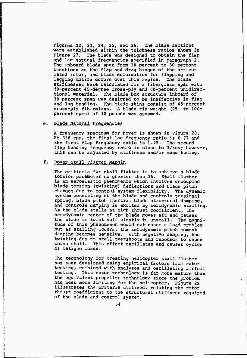
Figures 22, 23, 24, 25, and 26. The blade sections were established within the thickness ratios shown in Figure 27. The blade was designed to obtain the flap and lag natural frequencies specified in paragraph 2. The inboard blade span from 10 percent to 30 percent functions as the flap and drag hinges of the articu- lated rotor, and blade deformation for flapping and lagging motion occurs over this region. The blade stiffnesses were calculated for a fiberglass spar with 40-percent 45-degree cross-ply and 60-percent unidirec- tional material. The blade box structure inboard of 30-percent span vras designed to be ineffective in flap and lag bending. The blade skins consist of 45-percent cross-ply fiberglass. A blade tip weight (95- to 100- percent span) of 10 pounds was assumed.
e. Blade Natural Frequencies
A frequency spectrum for hover is shown in Figure 28. At 338 rpm, the first lag frequency ratio is 0.77 and the first flap frequency ratio is 1.25. The second flap bending frequency ratio is close to 3/rev; however, this can be adjusted by stiffness and/or mass tuning.
f. Hover Stall Flutter Margin
The critieria for stall flutter is to achieve a blade torsion parameter no greater than 36. Stall flutter is an aeroelastic phenomenon which involves uncoupled blade torsion (twisting) deflections and blade pitch changes due to control system flexibility. The dynamic system consisting of the blade and controls torsional spring, blade pitch inertia, blade structural damping, and controls damping is excited by aerodynamic stalling. As the blade stalls at high thrust coefficient, the aerodynamic center of the blade moves aft and causes the blade to twist sufficiently to unstall. The magni- tude of this phenomenon would not cause a load problem but as stalling occurs, the aerodynamic pitch moment damping becomes negative. With negative damping, the twisting due to stall overshoots and rebounds to cause worse stall. This effect oscillates and causes cycles of fatigue loads.
The technology for treating helicopter stall flutter has been developed using empirical factors from rotor testing, combined with analyses and oscillating airfoil testing. This rotor technology is far more mature than the equivalent propeller technology since the problem has been more limiting for the helicopter. Figure 29 illustrates the criteria utilized, relating the rotor thrust coefficient to the structural stiffness required of the blade and control system.
64
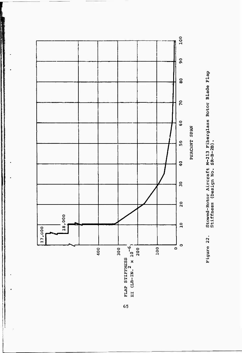
p
/
/
o o o
0 oo r O H 1 O I ^^| I
H
/
^
o o
O
o 00
o
o
O in
o rr
o
o
U
o o v f © O
o o '<-, o o ■«" n 3 N
X
H
zra CM • CM a H H EH 1 w
H EM w
& •0
h
0) TJ <d iH n M 0 +> 0 «
(C CO fO f-l Cn u 0) .a • •H ^» b pa
cs n I H m M 1
1 « aw •P • «H 0 nJZ ^ ü C M &
•H -H < to
0 U Q O"- ■p o to Ä CO
1 (U T3 C 0) IW S«w 0-H JJ +J W W
(N (N
(U M 3 0»
CM
65
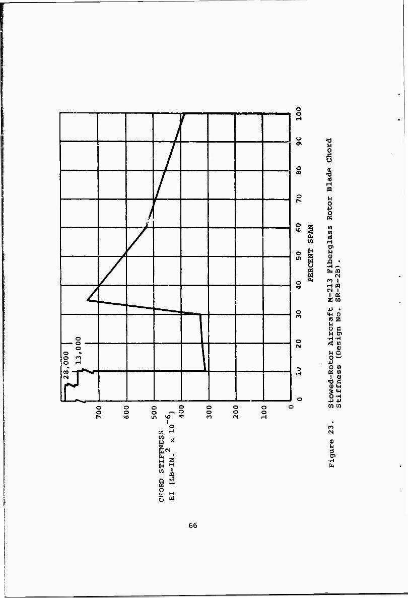
l i
/
/
j /
/
1 — _
- , -
o i o
o •» O PO O H 1
o o
(-1
o 00
o
o ID
O m
to
8
o
o
O O O O r^ VD
o o in
o ^ o
vo "• l o
o o
o o o
o H
W «
fe 2 H « EH H
CQ
S H
M 0 X! U
% (d H
u
01 0) a H 0> M 0) Ä • •H —
CM ro l H CQ « I I « S (0
Ü
3
ß t? H cn 0)
M Q 0 —
0 « I
no 0) ^-l i (4-1 OH
to to
0)
3 cn
66
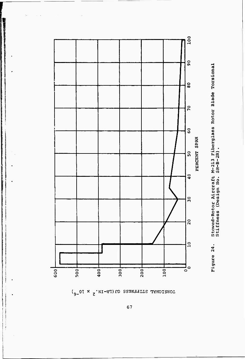
'
,
(
/
J f
J
o o
o o o o o O o o o o o o vo in ^ n (N H
o <r>
1 •H 0) M o 0 »
1 o OQ
r» U 0
o m CO (0
U <U
J3 • o in S5
s M-213 Fi
SR-B
-2B)
o TJ-
ircraft
ign
No.
o < m n
-Rotor
ess
(De
o -o c (N <U M-l
■p +J
o r-\
o )
•H
(ox x •Ni-eT)rD ssaNJJiis IVNOISHOX
67
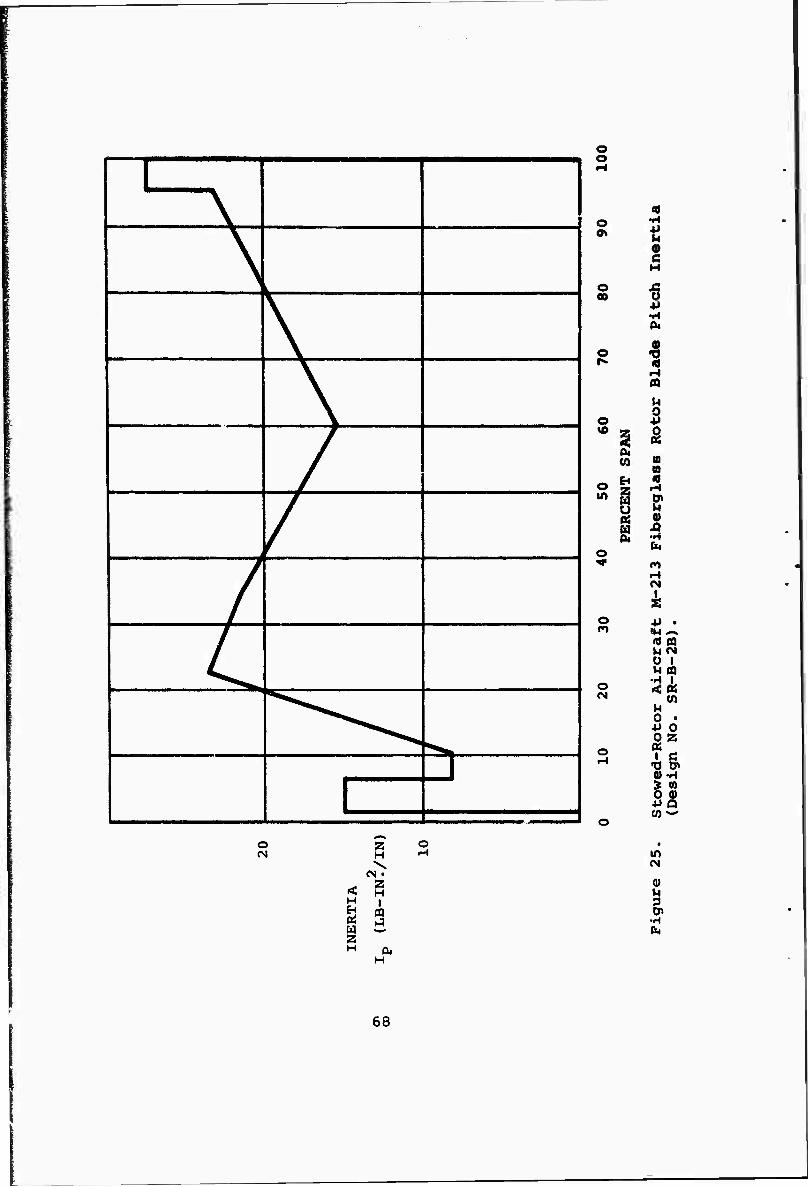
^A \
\
\
/
/
/
l^ ^^^Ni^^^
",^,
j l
o o
o
o 00
o
o
4J u s ja o
o
ä s (0 a ti « o H
in P1 Q U 01 (V H ij (U
CM
o P0
o CM
tN
k +» •
U (N O
< M 0
s I
-0 0)
CO
o ss
& •H
CO 0) Q
o 0) w
o rM
< H
s W Z H
2 H \
z H I m 9
H
s in
u 3
fc.
68
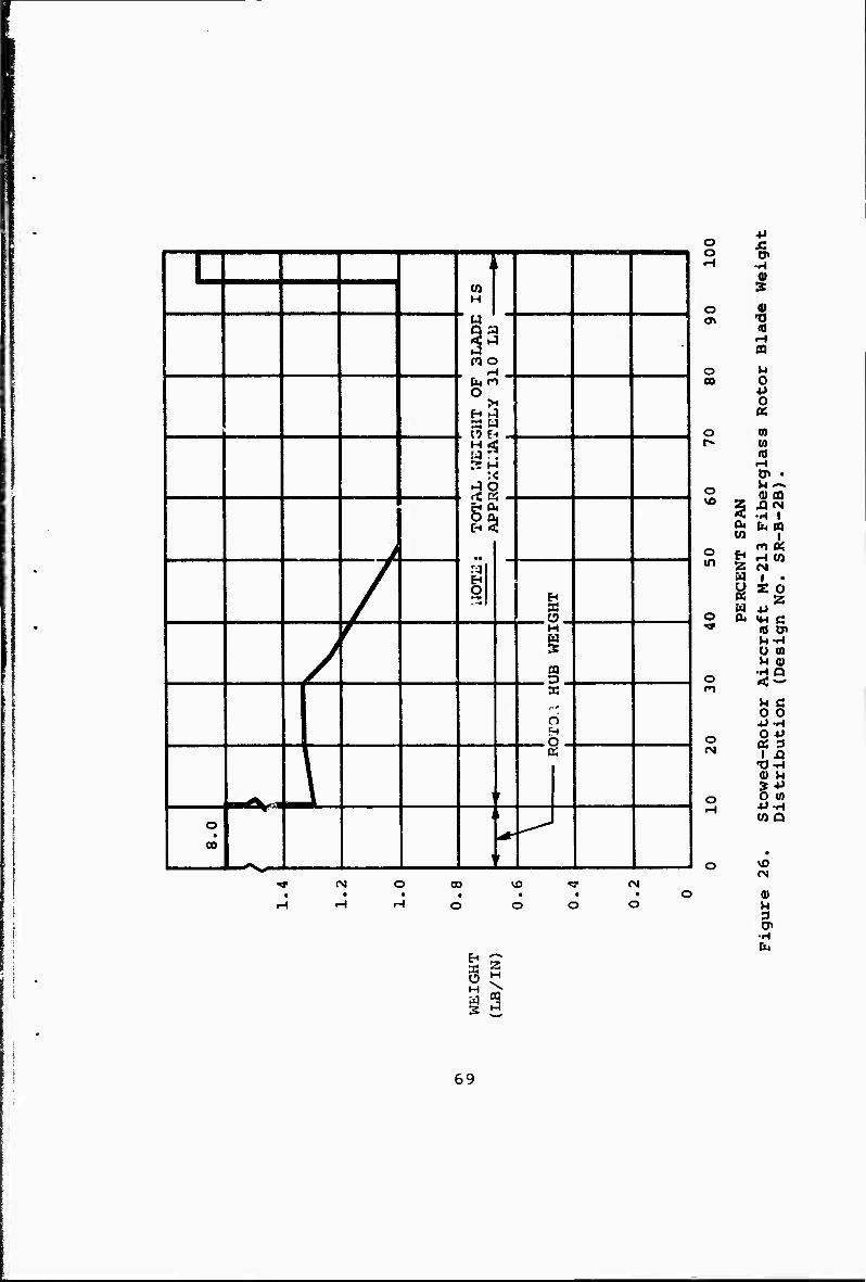
L 93
O >
a t . O E
H <
>
■i „
s
f
>
C-i <
/
ral
s
j J f f"' H
/ £ a
F
2- c
^, ^^f" - L r
o • 00
i i
L^ 1 1 i f 1 CO
o o
fM
u H M S
*J o Ä o O« »-•
3
o 0) o\
o M CO O
-P
1 o
rglass
o a) m VD ^
XJCM -H 1
D, fci A Ü) 1
o m Z
Hi CO CM
a 1 • y S 0 (£• z W 4J o P4 «H C
'W
ircra
Desig
o < — m M C 0 0
0 -P o OS 3 i^
wed-
trib
o O 0) »H 4JH
CO Q
O
• VO
0)
1 CM
CQ
69
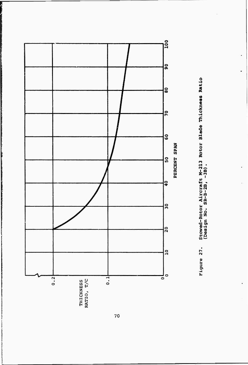
o •H
« o c X o
»4
s n fM-.
1 (Q S« •P «M • « n HtM 0 9 U ffl
•H I »cos
(0 M 0 • •M 0 fiz K
1 C •0 0» (U-H > n 0 0) 4JQ w w
• r- fN
0) M 3 CP
•--I b
70
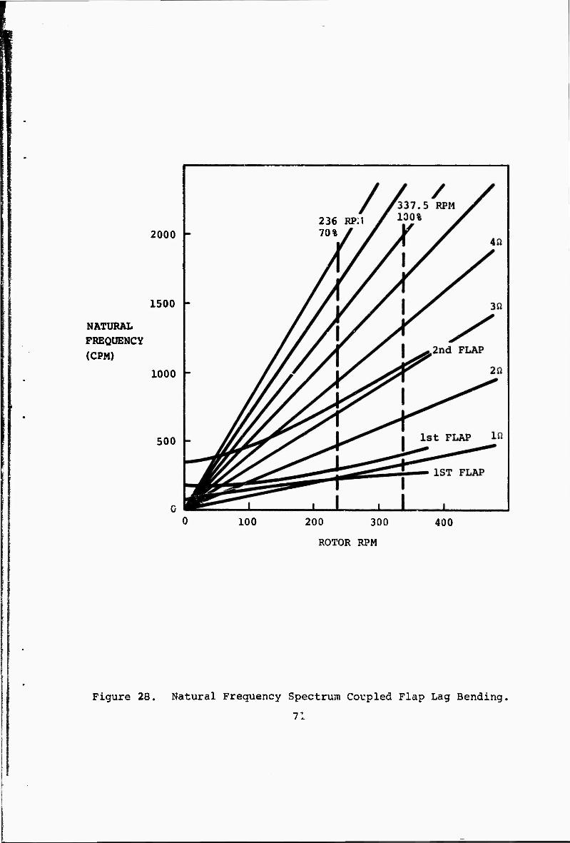
2000
1500
NATURAL FREQUENCY
(CPM)
1000 -
500
100
236 RP.l 70%
200 300
ROTOR RPM
400
Figure 28. Natural Frequency Spectrum Coupled Flap Lag Bending,
71
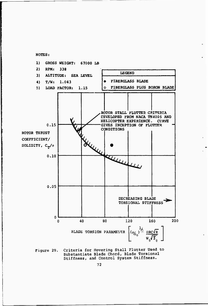
NOTES:
1) GROSS WEIGHT: 67000 LB
2) RPM: 338
3) ALTITUDE: SEA LEVEL
4) T/W: 1.043
5) LOAD FACTOR: 1.15
0.15
ROTOR THRUST
COEFFICIENT/
SOLIDITY, CT/o
0.10
0.05
LEGEND
• FIBERGLASS BLADE
O FIBERGLASS PLUS BORON BLADE
ROTOR STALL FLUTTER CRITERIA DEVELOPED FROM NACA TN4006 AND HELICOPTER EXPERIENCE. CURVE GIVES INCEPTION OF FLUTTER CONDITIONS
DECREASING BLADE TORSIONAL STIFFNESS"
40 80 120
BLADE TORSION PARAMETER
160
V. r- (p/ ) •■ flRCVR
Figure 29. Criteria for Hovering Stall Flutter Used to Substantiate Blade Chord, Blade Torsional Stiffness, and Control System Stiffness.
72
200
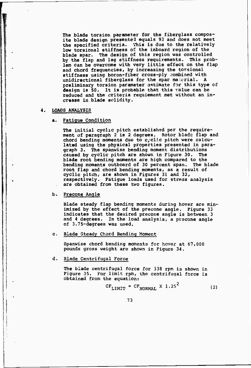
I
The blade torsion parameter for the fiberglass compos- ite blade design presented equals 93 and does not meet the specified criteria. This is due to the relatively low torsional stiffness of the inboard region of the blade spar. The design of this region was controlled by the flap and lag stiffness requirements. This prob- lem can be overcome with very little effect on the flap and chord frequencies, by increasing the torsional stiffness using boron-fiber cross-ply combined with unidirectional fiberglass for the spar male rial. A preliminary torsion parameter estimate for this type of design is 50. It is probable that this value can be reduced and the criteria requieroent met without an in- crease in blade solidity.
4. LOADS ANALYSIS
a. Fatigue Condition
The initial cyclic pitch established per the require- ment of paragraph 2 is 2 degrees. Rotor blade flap and chord bending moments due to cyclic pitch were calcu- lated using the physical properties presented in para- graph 3. The spanwise bending moment distributions caused by cyclic pitch are shown in Figure 30. The blade root bending moments are high compared to the bending moments outboard of 30 percent span. The blade root flap and chord bending moments, as a result of cyclic pitch, are shown in Figures 31 and 32, respectively. Fatigue loads used for stress analysis are obtained from these two figures.
b. Precone Angle
Blade steady flap bending moments during hover are min- imized by the effect of the precone angle. Figure 33 indicates that the desired precone angle is between 3 and 4 degrees. In the load analysis, a precone angle of 3.75-degrees was used.
c. Blade Steady Chord Bending Moment
Spanwise chord bending moments for hover at 67,000 pounds gross weight are shown in Figure 34.
d. Blade Centrifugal Force
The blade centrifugal force for 338 rpm is shown in Figure 35. For limit rpm, the centrifugal force is obtained from the equation:
" 2 I CFLIMIT " CFNORMAL X 1-25 (2)
i ' 73
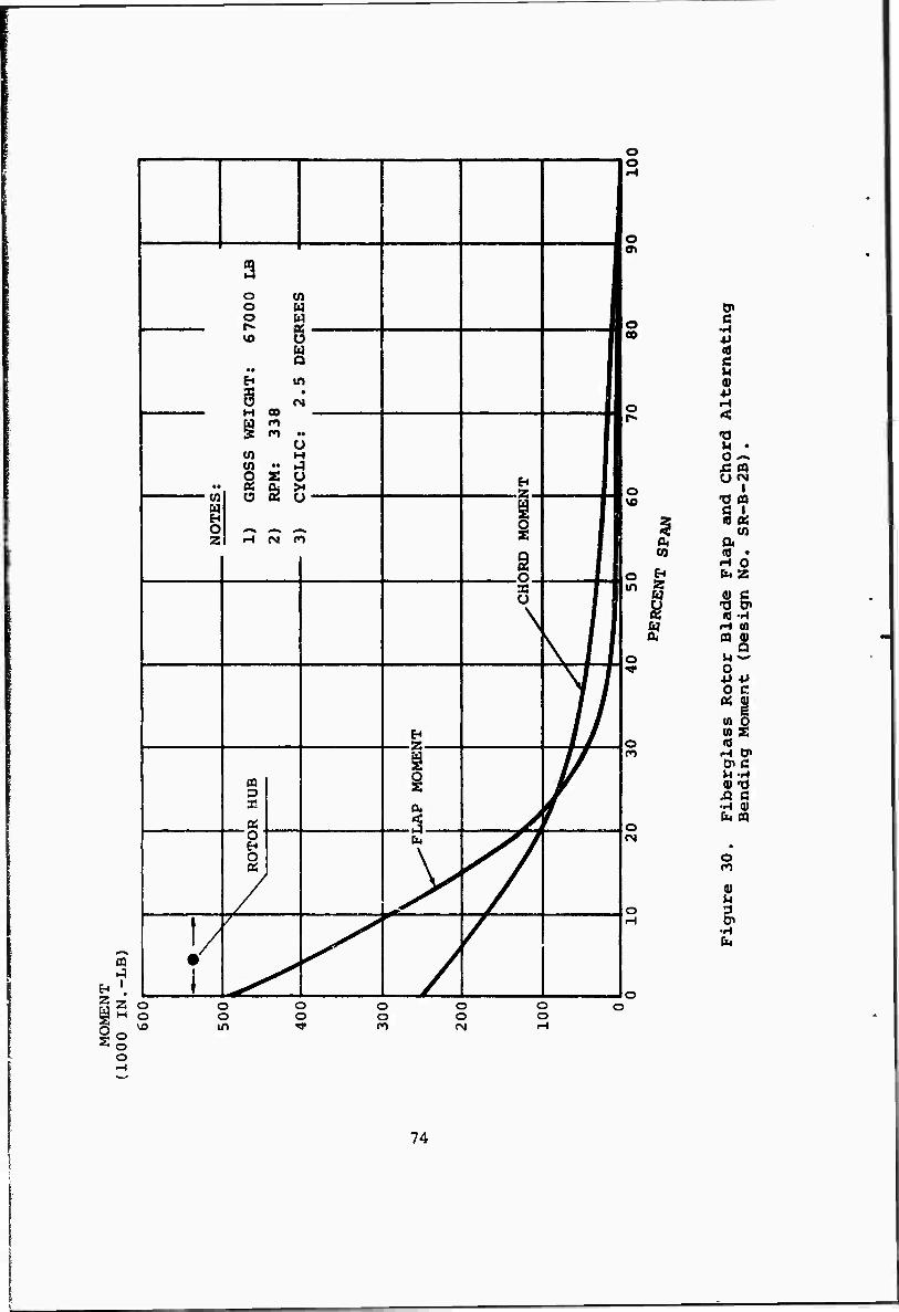
CQ
a H
a o o
1 1
3 o w o w O M
VD O M i Q i
• • ■ ti m i X i O CN i
1 U ■
W M i W " i4 i S s o ■
.. OS Dj >4 c^ i UJ <-l WM VJ 1 I o ^n <«, *^ i 1 Zi H tv rt i
g 1 n f S ■ u ■
\
N /i
H ►» // i 1/
CQ y 3! 04 w
! OS r^ SV 1 O-1
EH fa v^/
O \ ^^ /
7 >
< /
'/
/
A • ^ /
1 ^ /
o o
o w
0» o CO 5
•P
0 ■P
o
Chord Al
23}
.
o | \o •d a
% «a:
0. Oi CO
•H 0 o hi fa 2 in 2
H 0 C
S •a en
14 H (0 ft ««
o V4^ ■*
ss Roto
Moment
o <o n
Fibergl
Bending
o CN
i o 3 H
•H fa
o o
o o in
o o
o o
o o
O O
74
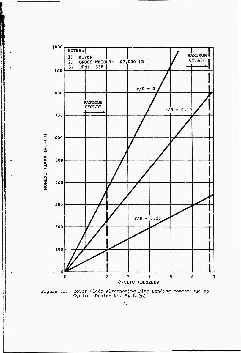
1000
3 i
o o o
2
900
800
700
600
500
400
300
200
100
Figure 31.
3 4 CYCLIC (DEGREES)
Rotor Blade Alternating Flap Bending Moment Due to Cyclic (Design No. SR-B-2B).
75
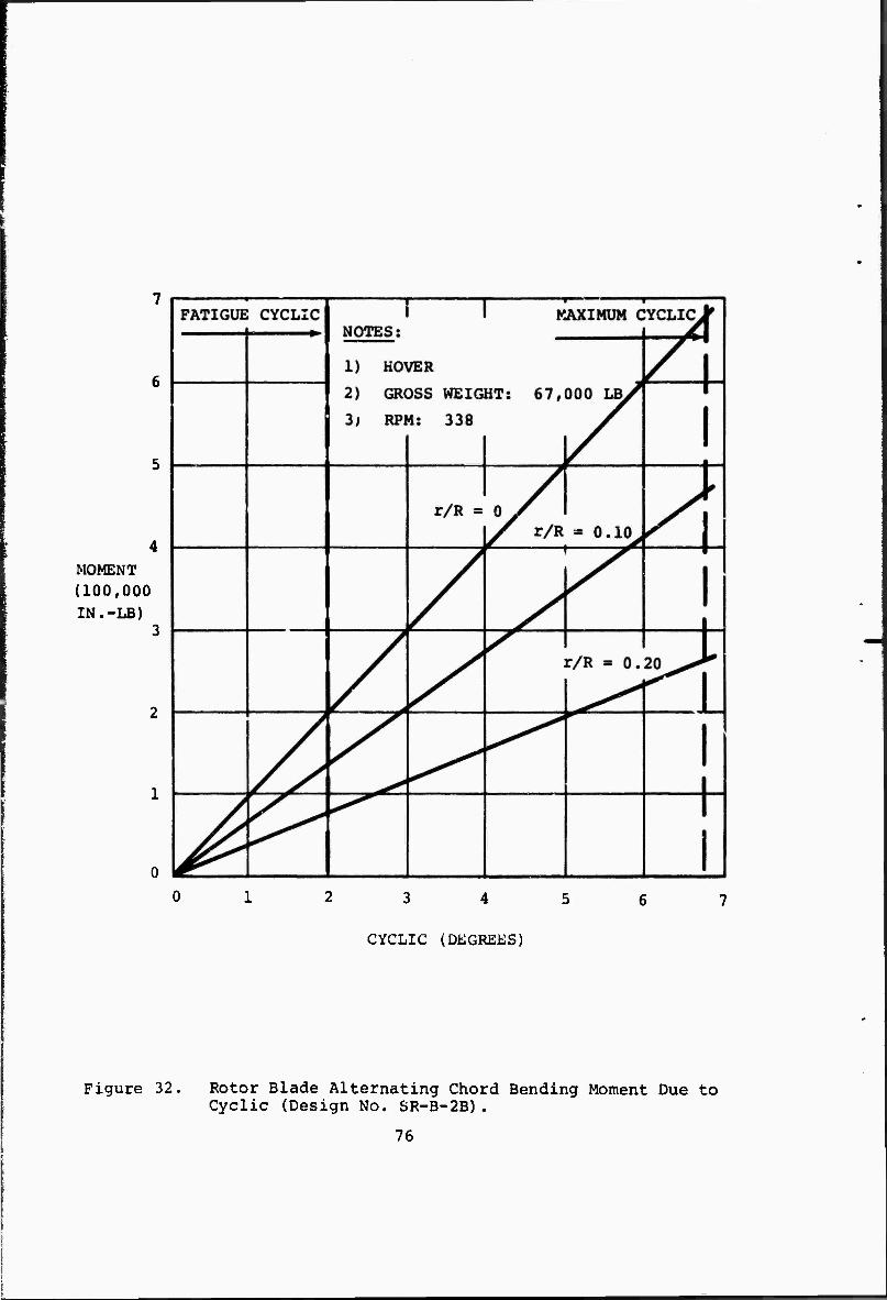
MOMENT (100,000 IN.-LB)
CYCLIC (DEGREES)
Figure 32. Rotor Blade Alternating Chord Bending Moment Due to Cyclic (Design No. SR-B-2B).
76
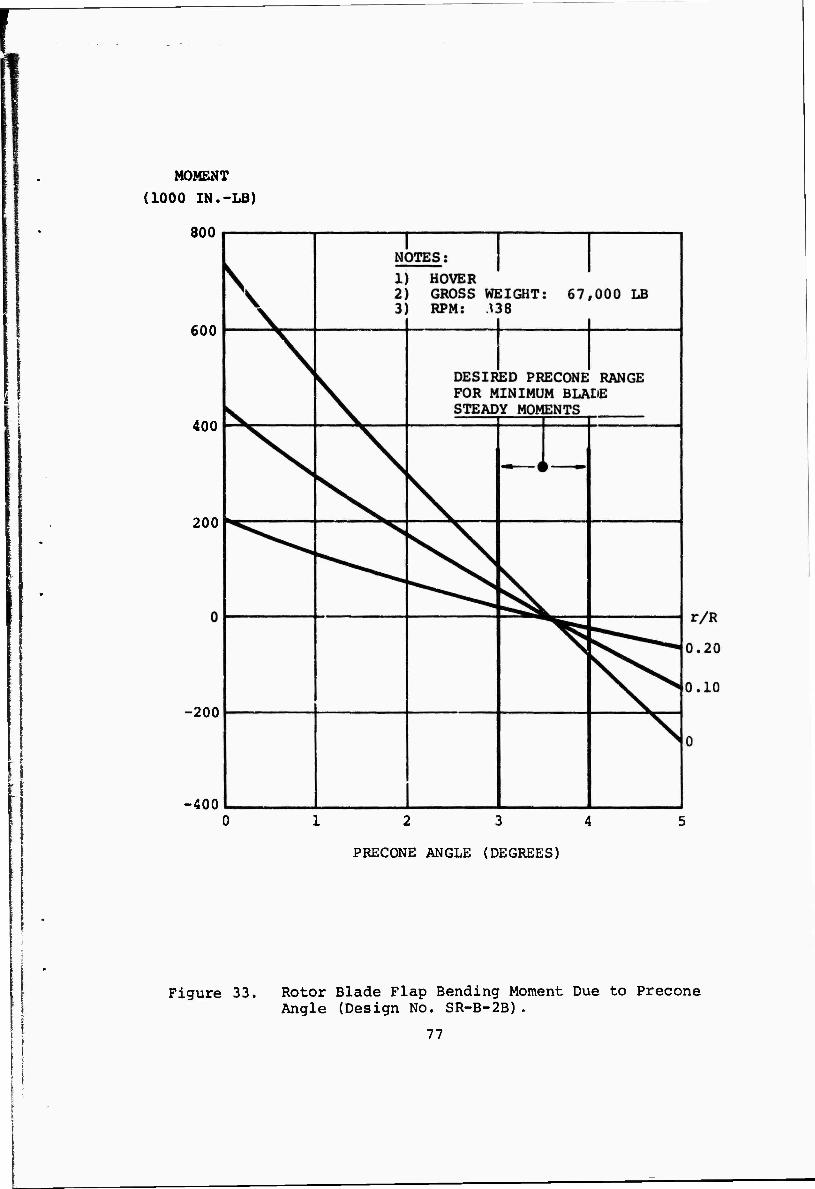
MOMENT
(1000 IN.-LB)
800
600
400
200
-200
-400 12 3 4
PRECONE ANGLE (DEGREES)
Figure 33. Rotor Blade Flap Bending Moment Due to Precone Angle (Design No. SR-B-2B).
77
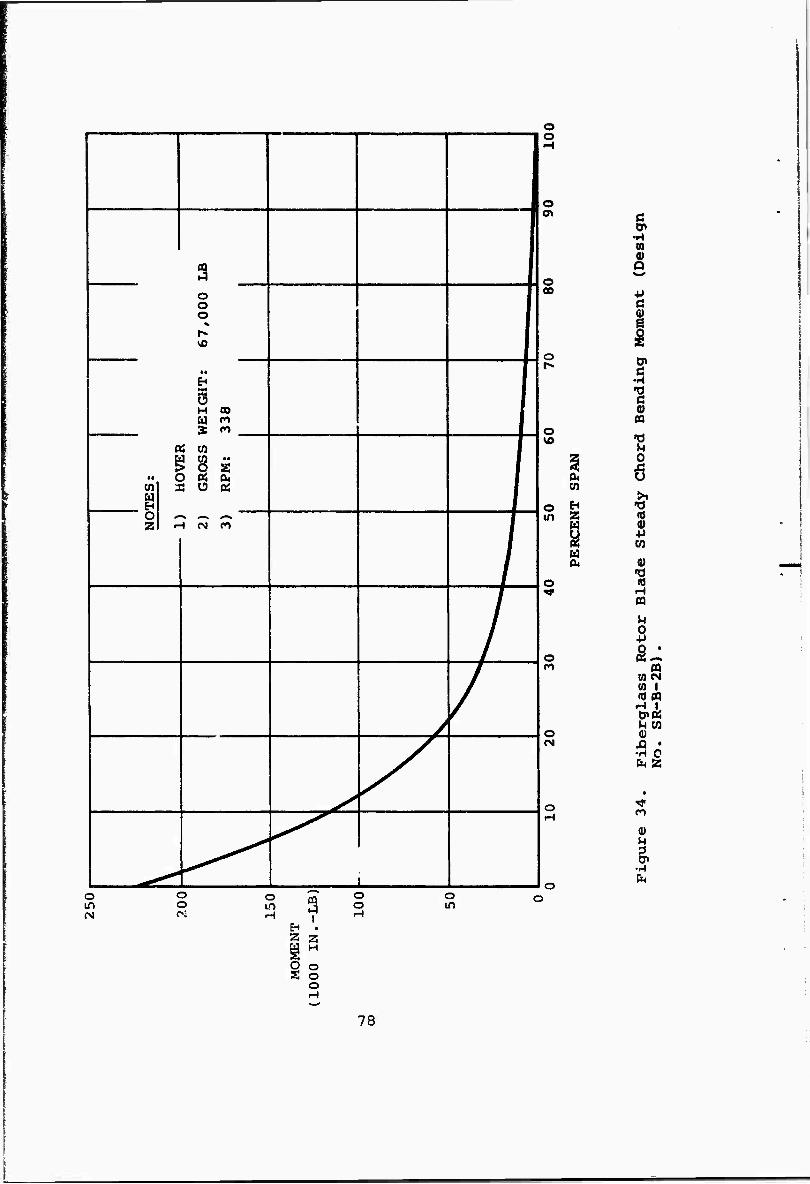
3 o o o r-
WE
IGH
T:
338
• • I en
0 B c 3 G
RO
SS
RPM
: 1 o z H CM n
/
/
/ /
^ /
i
o o
o
o oo
o
o vo
o in
o
o
O
w
EH 2 W s u 0«
o lA
O O
O
3 o o
o in
EH . 2 Z
§ 0 S o
o
ß cn
n
Q
■P
I ti
•H
c 0)
CO
■o u o
u
>1 •d
0> +i w
0)
«j H CO
u %
m W (S (0 I id n H I Cn« M en a> .fl • •H o CM Z
n
0) M
•r-l
78
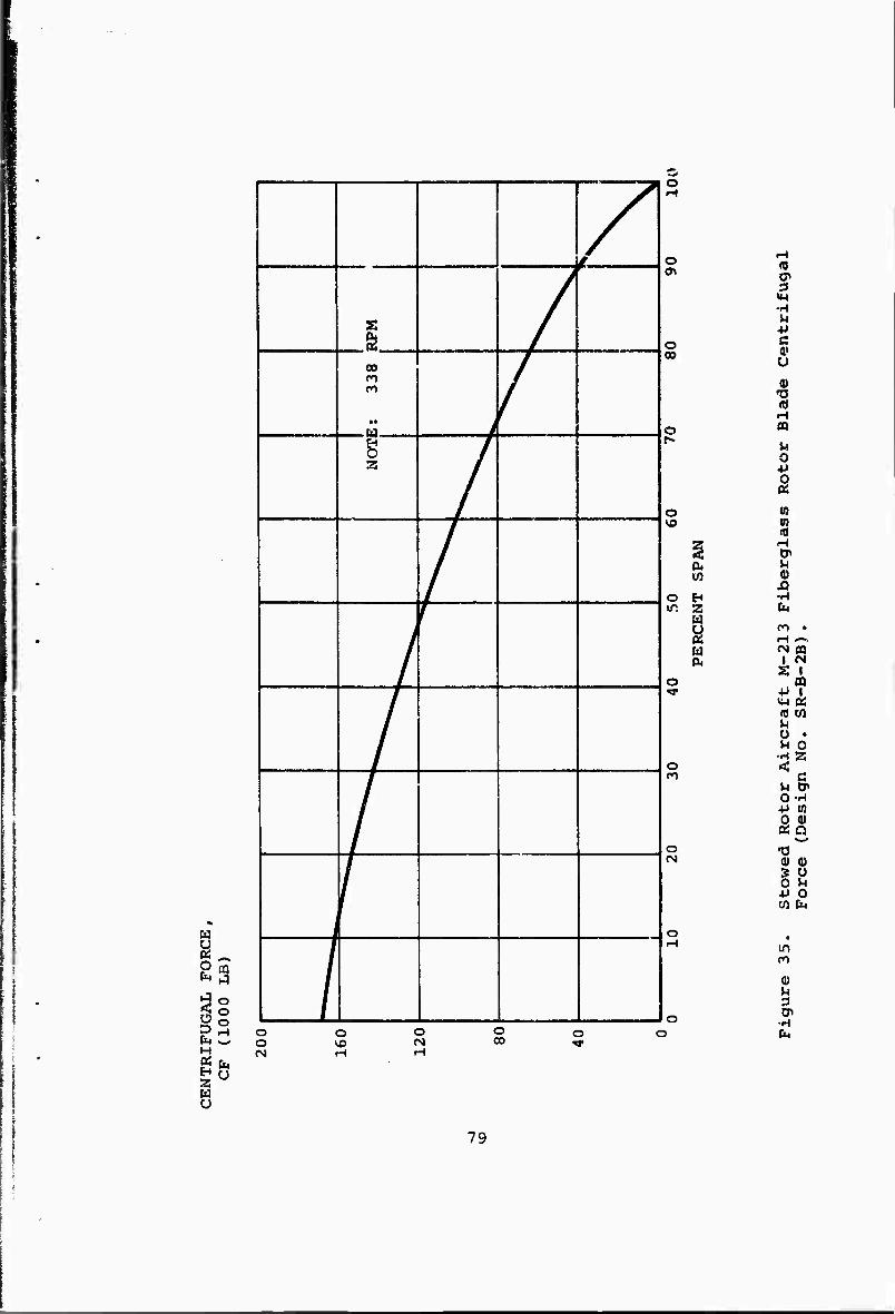
8 S3
I3 H g CM
s /
00 CO
•• > /
s 3
/
/
y r /
7 i '
o
O
o CO
o
o
o
o
o CM
ft.
Z W
O o CSJ
o o o 00
o 'S"
•H
e a» u
•s m
m to «
o» M (U XI •H b
m • H —. eg cQ l 01 S I
CD •P I
id co M ü • u 0 M 2
C •H en a) a
0) 0)
W fa
in
en fa
8 79
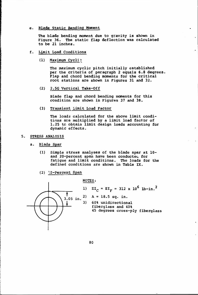
e. Blade Static Bending Moment
The blade bending moment due to gravity is shown in Figure 36. The static flap deflection was calculated to be 21 inches.
f. Limit Load Conditions
(1) Maximum Cyclic
The maximum cyclic pitch initially established per the criteria of paragraph 2 equals 6.8 degrees. Flap and chord bending moments for the critical root stations are shown in Figures 31 and 32.
(2) 2.5G Vertical Take-Off
Blade flap and chord bending moments for this condition are shown in Figures 37 and 38.
(3) Transient Limit Load Factor
The loads calculated for the above limit condi- tions are multiplied by a limit load factor of 1.25 tc obtain limit design loads accounting for dynamic effects.
5. STRESS ANALYSIS
a. Blade Spar
(1) Simple stress analyses of the blade spar at 10- and 20-percent span have been conducteu for fatigue and limit conditions. The loads for the defined conditions are shown in Table IX.
(2) \0-Percent Span
NOTES
EIC = EIF = 312 x 106 lb-in.2
A = 18.5 sq. in.
60% unidirectional fiberglass and 40% 45 degrees cross-ply fiberglass
80
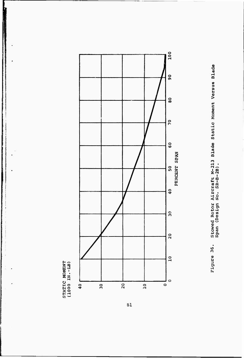
i i
z
H
EH ifi
3 i «
2 H
O O o H
0*
2 M U « a*
0) •o 10
CO
(0
> ■u c
i Ü
•H +> (0
w 0) X3 (0
n <N o«
1 CQ Xr*
■p m IM 1 to a; l-i CO ü n •
•H 0 <'Z
u c 0 Cn +J •H 0 m « Q)
Q TJ 0) » C 0 fl •p 04 w m
• VD n
0)
g, •H fa
81
|S
SS
CQ J
cn o w cß o w a
L_ o Pa £3- o « t- a o vo o u
Q m
•• P» tf» EH • fS u 5 n
M M CO Kj n .. 5 n a ••
Z U CO OH m .. u ^
1 •• S i S Cd U !• S >»
l/J o « cu u
>~. <-^ ^». —V
Z •-I CN n 'j' H id
g II
s 1 o if z il H ""'"" f 11 £-• 11
H < / Z
H / o | / «! I / ^ \ / 1 Q \ / 1
rt \ , f 1 w v 1 EH J^ / w s s /
h^ /
/
"^
J^
4 /
o o
O o
o o o
o o 00
o o VD
o o
o o
o o\
%* <W 0 0) >;
o CO EH
H «8 0
•K i>
o >><
Ü in
• N
o vo VI
0
§ «w
0. to w 4J c
O H un Z g
pa 0 u s (tf u cr 0« ß
•H o -a Tf c
0) cd
04 (0 M
o h m G) •0 (0 f-l CQ
o M 0
■P 0 «
O • H r^
ro
<B M 3 cn
O ■A CM
82
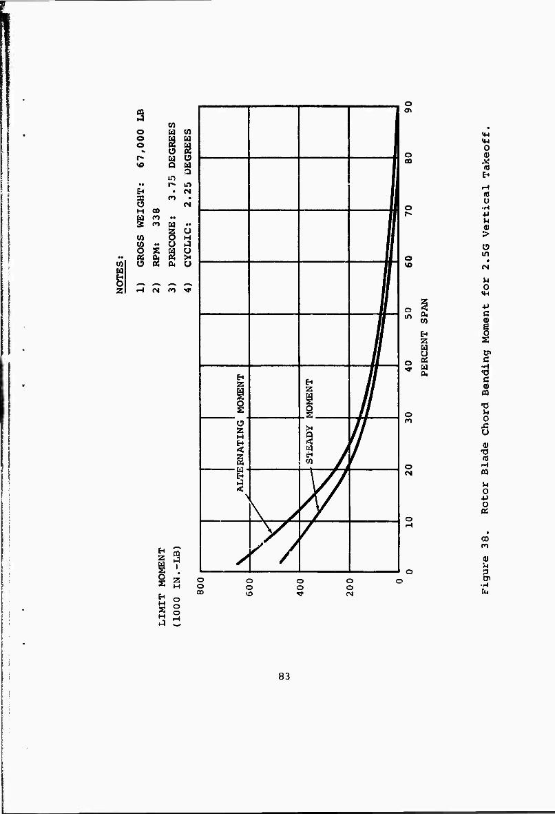
3
f
W o w (0 o U o s r^ w u vo Q § H r« in
EH • CN X cn • O CN H 00 »• * M M •• w o H to «• U J o S 1 u *• as S X
w o 0« u w fn o #—^ <—^ ^•^ ^** 2 rH (M n •»!•
: i
2
H
3 i
o o o
i
1 1
1 z
i Z
/
z H s 1 f \y 7
./ ^
o
o oo
o
o
o «. in a. w
B z u t.
o « rr w
04
o
o CM
o o oo
o o
o o
o o <N
«(-4
o 0) X (0
«0 Ü
-H -u
>
in •
M 0
«M
-P c 0)
0> c
•H
C
•a o u
-o (0 rH CQ
u 0 •p
00 n
0)
3 cr> fa
J 3
83
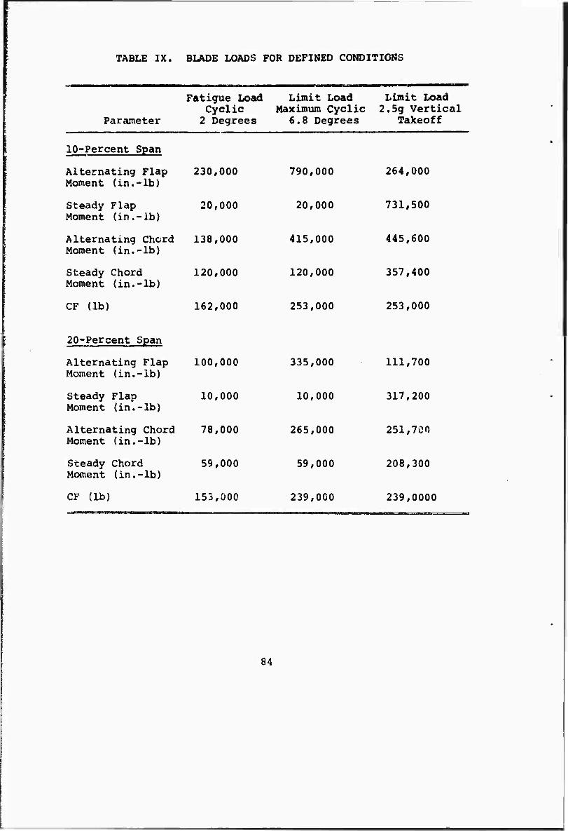
TABLE IX. BLADE LOADS FOR DEFINED CONDITIONS
Parameter
Fatigue Load Limit Load Limit Load Cyclic Maximum Cyclic 2.5g Vertical
2 Degrees 6.8 Degrees Takeoff
10-Percent Span
Alternating Flap Moment (in.-lb)
230,000 790,000 264,000
Steady Flap Moment (in.-ib)
20,000 20,000 731,500
Alternating Chord Moment (in.-lb)
138,000 415,000 445,600
Steady Chord Moment (in.-lb)
120,000 120,000 357,400
CF (lb) 162,000 253,000 253,000
20-Percent Span
Alternating Flap Moment (in.-lb)
100,000 335,000 111,700
Steady Flap Moment (in.-lb)
10,000 10,000 317,200
Alternating Chord Moment (in.-lb)
78,000 265,000 251,700
Steady Chord Moment (in.-lb)
59,000 59,000 208,300
CF (lb) 153,000 239,000 239,0000
84
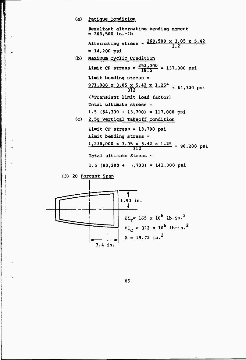
(a) Fatigue Condition
i
r
Resultant alternating bending moment » 268,500 in.-lb
Alternating stress
» 14,200 psi
268.500 x 3.05 x 5.42 XT
(b) Maximum Cyclic Condition
(c)
Limit CF stress = ^[g00 = 137,000 psi
Limit bending stress ~
971,000 x 3.05 x 5.42 x 1.25* ,- ,nn ' «y» = 64,300 psi
(♦Transient limit load factor) Total ultimate stress =
1.5 (64,300 + 13,700) » 117,000 psi
2.5g Vertical Takeoff Condition
Limit CF stress = 13,700 psi
Limit bending stress *
1,230,000 x 3.05 x 5.42 x 1.25 Qn -nn *< M = oU,lUU psi
Total ultimate Stress =
1.5 (80,200 + ,,700) = 141,000 psi
(3) 20 Percent Span
3.4 in.
"T~ 1.93 in.
El = 165 x ID6 lb-in.2
F
EIC = 322 x 106 lb-in.2
A = 19.72 in.2
85
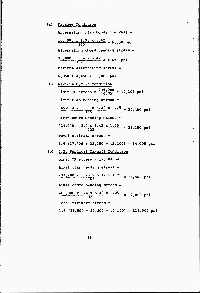
(a) Fatigue Condition
Alternating flap bending stress =
100y000 x 1.93 x 5.42 , -Kft . ' r-gr = 6,350 psi
Alternating chord bending stress =
78,000 x 3.4 x 5.42 —jn
fuv» ^v ^;-» ^ ^.■.> = 4 450 psi
Maximum alternating stress -
6,350 4- 4,450 > 10,800 psi
(b) Maximum Cyclic Condition
Limit CF stress = 2?|^jjj0 » 12,100 psi
Limit flap bending stress -
345,000 x 1.93 x 5.42 x 1.25 _ ~, ,nft . ■ mm — ^7,JOU psi
Limit chord bending stress «
324,000 x 3.4 x 5.42 x 1.25 _ ,, onn ^mt ' rj« = Z3,2.QIJ psi
Total ultimate stress =
1.5 (27,300 + 23,200 + 12,100) = 94,000 psi
(c) 2.5g Vertical Takeoff Condition
Limit CF stress = 12,100 psi
Li.tiit flap bending stress =
434,200 x 1.93 x 5.42 x 1.25 -. „n ^i —i ygw = 34,500 psi
Limit chord bending stress =
460,000 x 3.4 x 5.42 x 1.25 „ Qnn ,. «Tsj = JZ,0UU pSl
Total ultimat0 stress =
1.5 (34,500 + 32,800 + 12,100) = 119,000 psi
86
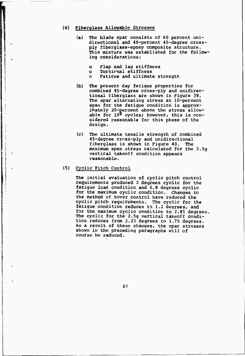
(4) Fiberglass Allowable Stresses
(a) The blade spar consists of 60 percent uni- directional and 40-percent 45-degree cross-
1 ply fiberglass-epoxy composite structure. | This mixture was established for the follow- I > ing considerations:
I o Flap and lag stiffness [ o Torsicnal stiffness I o Fatique and ultimate strength
\ (b) The present day fatigue properties for l combined 45-degree cross-ply and unidirec-
tional fiberglass are shown in Figure 39. The spar alternating stress at 10-percent
f span for the fatigue condition is approx- ! imately 20-percent above the stress allow-
able for 108 cycles; however, this is con- sidered reasonable for this phase of the
; design.
(c) The ultimate tensile strength of combined I 45-degree cross-ply and unidirectional \ fiberglass is shown in Figure 40. The I maximum span stress calculated for the 2.5g j • vertical takeoff condition appears j reasonable. I
| • (5) Cyclic Pitch Control
I The initial evaluation of cyclic pitch control | requirements produced 2 degrees cyclic for the
fatigue load condition and 6.8 degrees cyclic for the maximum cyclic condition. Changes to the method of hover control have reduced the cyclic pitch requirements. The cyclic for the fatigue condition reduces to 1.2 degrees, and for the maximum cyclic condition to 2.85 degrees. The cyclic for the 2.5g vertical takeoff condi- tion reduces from 2.25 degrees to 1.75 degrees. As a result of these changes, the spar stresses shown in the preceding paragraphs will of course be reduced.
87
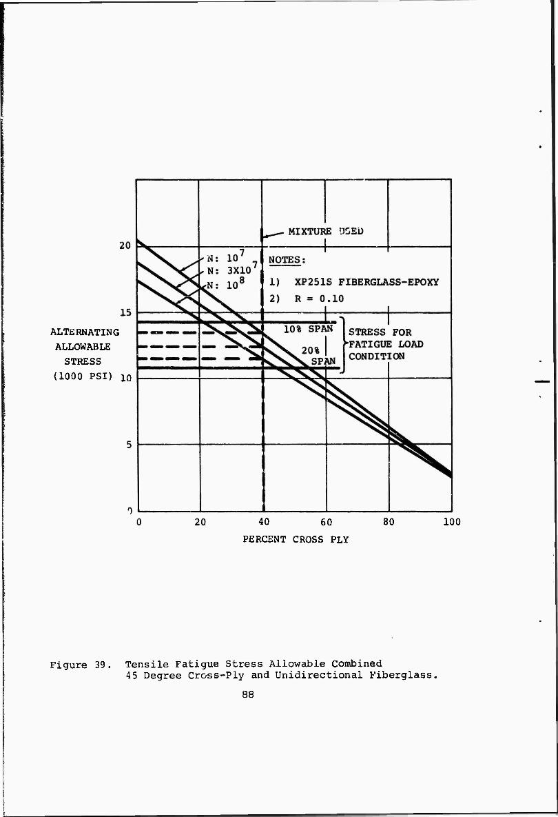
ALTERNATING ALLOWABLE
STRESS
(1000 PSI) 10
40 60 80
PERCENT CROSS PLY
100
Figure 39. Tensile Fatigue Stress Allowable Combined 45 Degree Cross-Ply and Unidirectional Fiberglass,
88
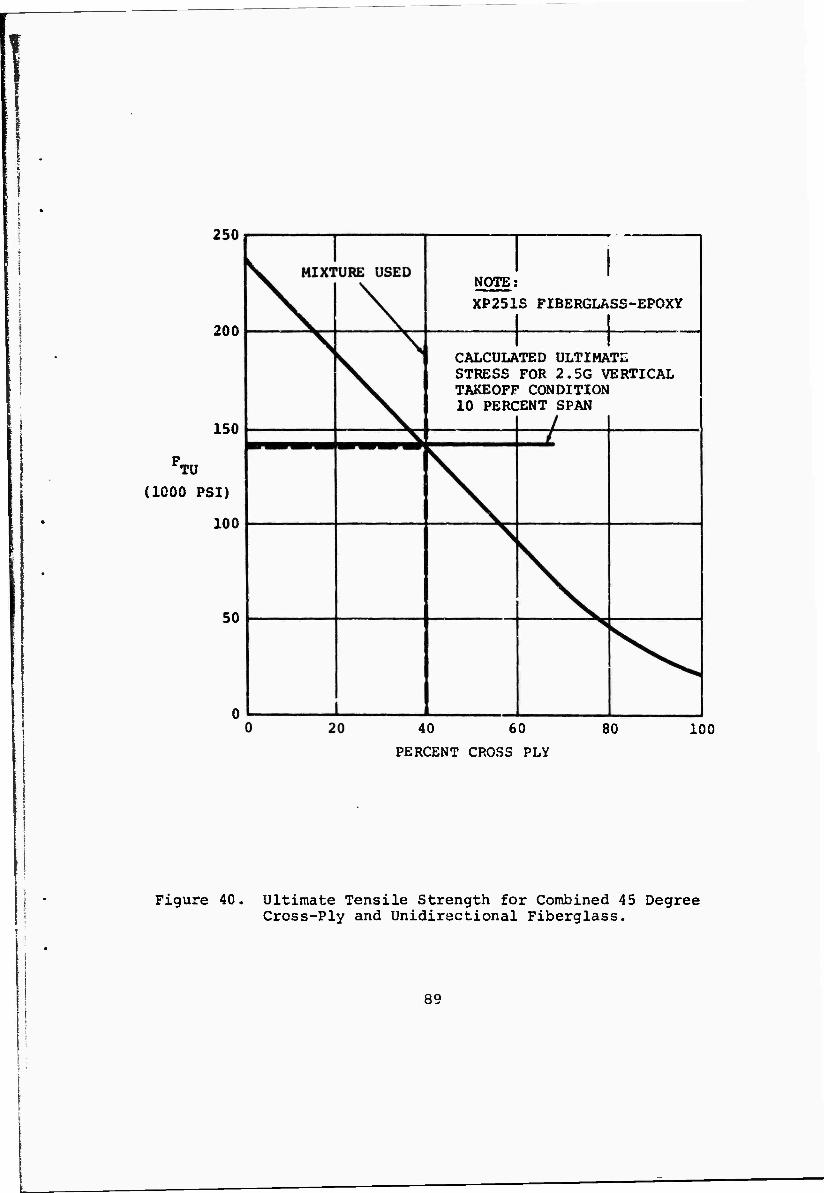
250
200
150
FTÜ
(1000 PSI)
100
50
NOTE;
XP251S FIBERGLASS-EPOXY
CALCULATED ULTIMATE STRESS FOR 2.5G VERTICAL TAKEOFF CONDITION 10 PERCENT SPAN
40 60
PERCENT CROSS PLY
100
Figure 40. Ultimate Tensile Strength for Combined 45 Degree Cross-Ply and Unidirectional Fiberglass.
89
6. CONCLUSIONS AND RECOMMENDATIONS
a. Conclusions
The blade preliminary design study indicates that a satisfactory hingeless rotor design can be achieved using fiberglass as the primary material. For the all-fiberglass blade designs considered, the criteria for stall flutter was not met. This was mainly due to the relatively soft spar over the inboard region of the blade required in order to meet the first flap and lag frequency criteria. In the even., that future modifications to the all-fiberglass blade to meet the criteria are unsuccessful, acceptable torsional stiffnes? can be achieved by using boron cross-ply over the inboard region without substantial increase in bending stiffnesses.
The conditions evaluated for fatigue and ultimate strength produced reasonable blade spar stresses.
The blade weight based on the preliminary design compares favorably with the target weight.
b. Recommendations
(1) Establish detailed criteria for all flight mode?.
(2) Refine blade section properties and stiffness calculations.
(3) Continue work toward increasing torsional stiff- ness in order to meet stall flutter criteria.
(4) Continue to improve and refine the design for producibiiity and cost reduction.
(5) Establish loads and deflection criteria for conversion.
(6) Establish criteria to insure satisfactory structural dynamic characteristics during conversion.
(7) Conduct a detailed structural analysis of the blade retention system.
(8) Evaluate the structural integrity of the blade for additional design load conditions.
(9) Establish a criteria for lightning strike protec- tion, and investigate means of meeting the criteria.
90
\ :
SECTION VI
HUB AND BLADE FOLD MECHANISM
1. OBJECTIVES
*• Functional Objectives
The hub assembly shall function in the manner of a conventional helicopter hub in hovering flight, but be so designed that, it may perform satisfactorily through the transition from vertical to horizontal operation. In addition, a means of stopping the blades in-£xight at a discrete azimuth location, and folding them in such a manner that they lie flush with the nacelle contour shall be provided. Also, the folding process shall be reversible.
b. Design Objectives
| (1) The rotor system shall be designed to meet the 5 structural, kinematic, and dynamic response I criteria dictated by stability and performance I • characteristics of the aircraft throughout its I • operating envelope and mission profile. i I (2) The interaction between the hub-and-fold system I • and other aircraft systems shall not result in I unacceptable dynamic characteristics, such as | excessive structural loads or vibration duriug
normal operation.
(3) The number of critical components shall be kept to the practical minimum through the use of redundant components, multiple load paths, and/or long design life, where applicable.
(4) Fail safe design philosophy is mandatory for all critical components.
(5) The design is to be flexible enough to permit future growth, where applicable, without degrading performance, interchangeability, or other objec- tives.
(6) The rotor system shall accomplish its specification tasks while maintaining high mission reliability for the life of the vehicle.
91
Consideration shall be given in the early design phases to ensure that these objectives are achieved while keeping operational costs to a minimum, so that high reliability may minimize spares, and commonality of parts minimize inventory. The system shall be sufficiently rugged to prevent handling damage.
(7) The rotor system shall exhibit maximum combat survivability.
(8) Ease of maintenance shall be insured by giving consideration, in the early design phases, to the provision of component accessibility, design for minimum special tool requirements, and otherr "built in" maintenance aids.
(9) The rotor system shall be designed with proper emphasis on producibility, so as to keep cost as low as possible within the total system function, safety reliability, maintainability, and surviv- ability goals, as outlined above, while maintain- ing realistic cost and time schedule.
2. DESIGN CRITERIA
a. The rotor hub shall be of a hingeless type with provi- sions for collective and cyclic pitch control together with full feathering and blade folding.
b. Blade feathering rate shall meet the response require- ments given in Appendix I and shall not limit the rate of rotor spinup or stopping during conversion.
c. Consideration shall be given to providing a means for detecting and reducing the effects of gusts and maneuver on rotor hub and blade stresses.
d. The rotor-fold mechanism shall be designed to operate safely at 1.5 times normal g under the following condi- tions: Speed range equal to 1.2 x flaps down stall speed or the greater of (1.2 x flap down stall speed + 50 knots) or 1.2 x flaps up stall speed, all at 1.5 times normal g.
e. Time between overhauls shall be a minimum of 500 rotor hours.
f. All rolling element bearings shall have an analytical determination of an L10 life in excess of the hub TBO.
92
g. The rotor shall be capable of operating at any shaft angle of attack from -10* to +110° for a velocity envelope to be determined from all hover, transition, conversion, and conventional rotor flight requirements.
h. Rotor components shall be designed for unlimited life. Alternating loading is based on the usage of 25% of the most severe case of pitch or yaw control availability, over and above the requirement to maintain a 10 inch center of gravity moment arm offset in hover. This criteria will be used until a comprehensive fatigue spectrum is established.
DESIGN
a. General
The rotor system described in this phase is a hingeless or rigid type in which the hub has provision for blade folding, cyclic and co-Tective pitch change, and feathering preparatory to folding.
There are no mechanical hinges for flapping or lag- rotor-blade motion.
b. Description of Folding Tilt Rotor Hub and Fold Mechanism
Figure 41 depicts the basic features currently en- visioned as necessary in the present folding-tilt- rotor hub mechanism. The basic four bladed propeller hub mechanism is provided; it consists of a central octagonal box structure with a family of lugs arranged in a pattern of four sets around each blade station. These lug sets fit exactly with mating lug sets in each pitch change bearing housing.
The aft two sets of lugs, at any discrete blade station, are constantly in mesh with the matching lug sets in the pitch housing via the blade fold hinge pins. The other set of lugs in each respective member is provided to selectively lock the blade pitch change bearing housing in rotor flight, or to release the blade hous- ing during the fold cycle. A set of two hydraulically- locked pins for each blade are engaged to provide posi- tive blade retention. Tho blade folding motion (appro- ximately 90°) and synchronization is accomplished by the outer folding link, the piston, the inner folding link, and the hydraulic rotary vane folding actuator. The blade folding motion is accompanied by pitch change motion, which rotates the blade to a flat position dur- ing the last portion of the foldback angular motion. This pitch change with fold motion is provided by a
93
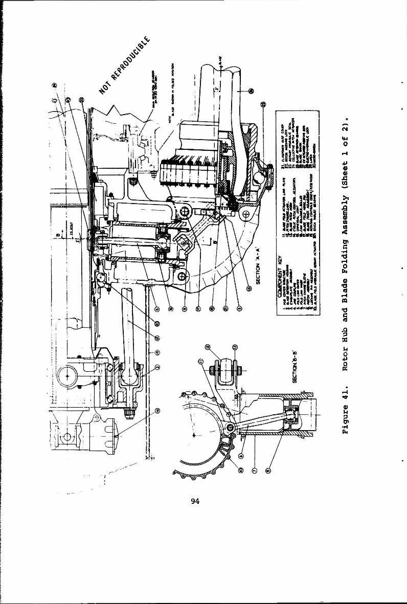
M «8
liiHlil
hi*11 mmi
'.SI3»»
•I P|.
O
CO
n en
a •a i-i
r-»
Ä
S
(0 u p 0>
•H fa
94
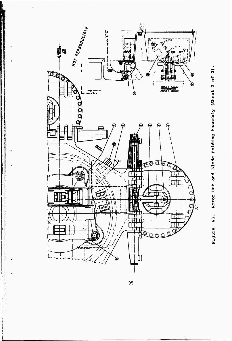
O
+> 0)
£
n m
c
tH O
HI A
T) C «J
K
»4 o +»
0)
■H
95
piston and roller assembly riding in parallel, keyway- type slots with helical cam slot endings connected to the outer fold links.
Thus, at the initiation of blade folding, the blade is in a feathered position. The parallel keyway type slots accommodate the constant feather angle with fold needed, until, at the last instant of travel, the blade is rotated by the helica] cam slots.
The outer fold link provides the torsional connection between the piston and the blade retention. When the blade is deployed (rotor flight position), the outer fold link is pulled into the keyway-grooved cylinder by the piston. A pair of interlocking jaw faces are brought into mesh, thus providing a solid high- torsional-rigidity connection between the pitch change sleeve and the blade. The hub retention area is, therefore, prepared for fully effective rotor flight control.
c. Pitch Change Mechanism
Pitch change is accomplished through a dual- hydraulically-powered helicopter-type control swash- plate which transmits blade pitch change, through pitch links, to the blade pitch change sleeve. Dif- ferent pitch link-motion requirements at the end attachment to the swashplate and pitch arm have dic- tated the use of a pitch link with an integral spheri- cal end bearing at the swashplate end and a conventional rod end bearing at the pitch arm end.
The swashplate assembly is gimbal-supported on a translating tube to allow for collective pitch and feathering pitch change. This sliding tube forms the primary structural component of the actuation package which, in addition to supporting the swashplate, houses dual hydraulic collective actuators and a collective lock unit. A dual pitch actuator system mounted at the forward end of the tube controls swashplate tilt for cyclic pitch change.
The actuation package is contained in the hub and transmission-mounted controls support tube (stack) with actuator forces reacted by the forward support thrust bearing. Control moment forces are reacted by the same bearing and by a steady mount at the aft face of the transmission. The control support thrust bearing transfers the actuator reaction forces into the hub structure so that the aft steady mount transfers only shear and torque reaction forces to the transmission
96
end cover. The swashplate rotating on tin ring is driven by the rotating hub through a pair (for balance) of active drive shoes and backup or safety drive shoes. These shoes ride in appropriate drive slots.
d. Lubrication Systems
All bearings are oil lubricated. The complete pitch change mechanism and blade retention systems are totally enclosed by a controls cover, which also serves as a rotating oil sump, and a set of elastomer boots, one at each blade station. While the system is rotating, oil is continually supplied to the bear- ings from a central oil gallery which is supplied with oil picked up by a non-rotating scoop tube immersed in the rotating oil sump. Oil retention cups are pro- vided at all rolling element bearings so that a "safe" oil supply is maintained for start up and for loss of sump oil through oil seal failure or battle damage.
e. Rotor Indexing Lock
Provision must be made in the rotor system to stop the rotor at either of two discrete locations, so that folding and accurate stowing of the rotor blades may be achieved. In previous studies, a rotor brake and an indexing drive motor were proposed to accomplish this procedure. However, in this report a less compli- cated method is proposed (see Figure 41}. This provi- sion consists of two hinged locking dogs, which, during operation at normal rotor rpm, are forced out- ward by centrifugal force. These locking dogs spring inward when rpm is reduced, and they depress two spring-loaded latches as they pass over them. A feather blade pitch is selected that will, after stop- ping the rotor, aerodynamically initiate reverse rota- tion. The dogs then contact the reverse (upright) faces of the latches and the rotor.
This contact operates a micro-switch within the latch which triggers an electro-hydraulic locking bolt that positively locks the rotor in position. Cross-coupling of the micro-switches and contact sensing of locking dogs would insure against switch failure or rotor bounce.
f. Spinner
An aerodynamic spinner is designed in three sections. The forward or nose section is quickly removable to provide access to rotor system test points. The mid or ogive section covers the general area of the
97
rotating oil sump and may also be built in several radial segments for easy removal and fabrication. The aft or skirted section is contoured to fit around each blade station and carries hinged doors which extend and retract in phase with the blade fold motion thereby providing smooth aerodynamic fairing over the retracted folded blades. All spinner shells are made of fiberglass-honeycomb construction and attach to sub- structure frames built over the forward hub and con- trols cover region.
g. Blade Vernier Adjustment - Tracking
Blade pitch vernier adjustment is provided for by using a screw jack operated dual spline concept. The dual spline sleeve consists of a helical spline and a straight spline. The axial motion, imparted to the dual spline sleeve by the screw jack, positions the blade with respect to the jaw clutch plate, and thus, provides a positive blade tracking means. All adjust- ment is provided with positive lock means to insure continuous safe operation at any setting.
h. Aids
Provisions are made for locating a rotor systems ground test panel and slip rings on the forward face of the controls cover (rotating sump). These items would be a part of a failure detection indication system for the non-rotating components. Provision could be made for ground check-out during general maintenance inspections, or, if desired, an advanced version could be developed to provide cockpit readout. Advanced systems will probably require that this second system be specified as standard equipment in the future. Structural inte- grity or condition monitors can be used in many of the subsystem areas to enhance in-flight safety, and to insure flying in safe time periods on all components.
i. Safety Features
A zero-degree cyclic pitch lock is incorporated into the cyclic actuator system to insure that there will be no cyclic pitch present on the rotor when the nacelle is in the full down position. This lock is mechanically capable of holding the swashplate stable at zero-degree cyclic in case of loss of hydraulic power to the cyclic actuators in propeller mode. At the aft end of the collective actuators, the infinite position lock, with emergency electrical override for feathering (a manual pitch) change, is provided for additional safety in transition in case of loss of sufficient hydraulic power to the collective-feathering actuator.
98
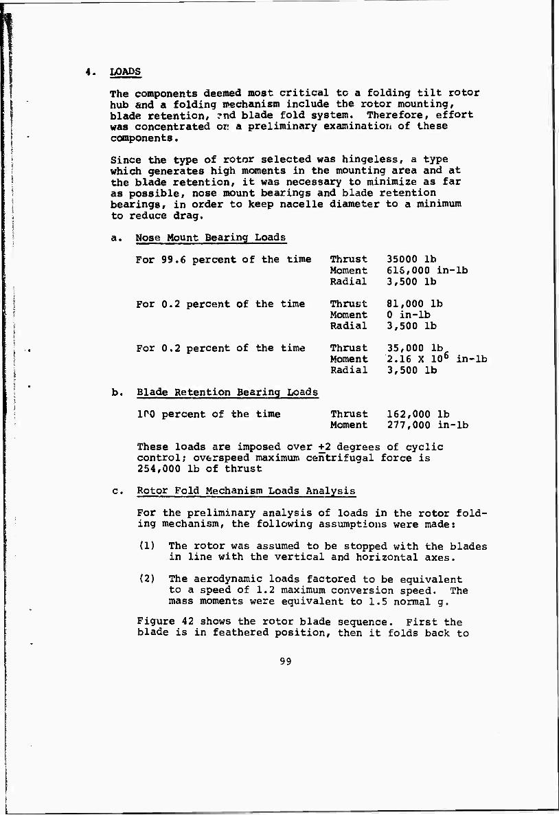
4. LOADS
The components deemed most critical tc a folding tilt rotor hub and a folding mechanism include the rotor mounting, blade retention, ?nd blade fold system. Therefore, effort was concentrated or; a preliminary examination of these components.
Since the type of rotor selected was hingeless, a type which generates high moments in the mounting area and at the blade retention, it was necessary to minimize as far as possible, nose mount bearings and blade retention bearings, in order to keep nacelle diameter to a minimum tc reduce drag.
a. Nose Mount Bearing Loads
For 99.6 percent of the time Thrust 35000 lb Moment 616,000 in-lb Radial 3,500 lb
For 0.2 percent of the time Thrust 81,000 lb Moment 0 in-lb Radial 3,500 lb
For 0.2 percent of the time Thrust 35,000 lb Moment 2.16 X 10⁶ in-lb Radial 3,500 lb
b. Blade Retention Bearing Loads
100 percent of the time Thrust 162,000 lb Moment 277,000 in-lb
These loads are imposed over +2 degrees of cyclic control; overspeed maximum centrifugal force is 254,000 lb of thrust
c. Rotor Fold Mechanism Loads Analysis
For the preliminary analysis of loads in the rotor fold- ing mechanism, the following assumptions were made:
(1) The rotor was assumed to be stopped with the blades in line with the vertical and horizontal axes.
(2) The aerodynamic loads factored to be equivalent to a speed of 1.2 maximum conversion speed. The mass moments were equivalent to 1.5 normal g.
Figure 42 shows the rotor blade sequence. First the blade is in feathered position, then it folds back to
99
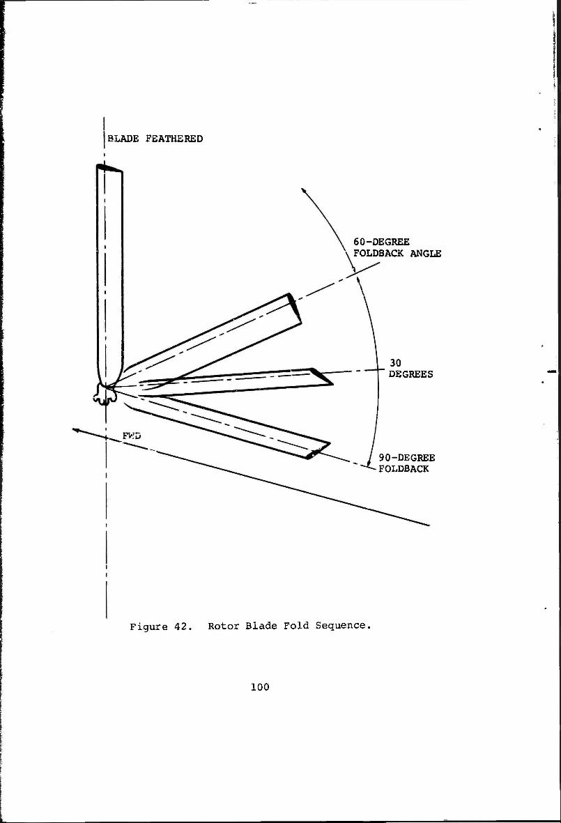
BLADE FEATHERED
60-DEGREE FOLDBACK ANGLE
30 DEGREES
90-DEGREE FOLDBACK
Figure 42. Rotor Blade Fold Sequence,
100
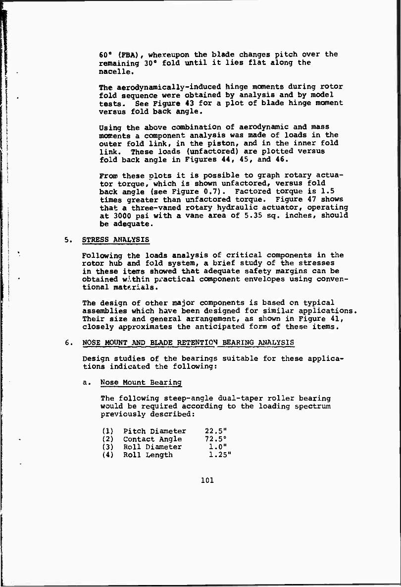
. I
60° (FBA), whereupon the blade changes pitch over the remaining 30° fold until it lies flat along the nacelle.
The aerodynamically-induced hinge moments during rotor fold sequence were obtained by analysis and by model tests. See Figure 43 for a plot of blade hinge moment versus fold back angle.
Using the above combination of aerodynamic and mass moments a component analysis was made of loads in the outer fold link, in the piston, and in the inner fold link. These loads (unfactored) are plotted versus fold back angle in Figures 44, 45, and 46.
i
From these plots it is possible to graph rotary actua- tor torque, which is shown unfactored, versus fold back angle (see Figure 0.7). Factored torque is 1.5 times greater than unfactored torque. Figure 47 shows
! that a three-vaned rotary hydraulic actuator, operating | at 3000 psi with a vane area of 5.35 sq. inches, should [ be adequate.
I 5' STRESS ANALYSIS |
| *■ Following the loads analysis of critical components in the „ I rotor hub and fold system, a brief study of the stresses
in these items showed that adequate safety margins can be obtained w.'.thin px-actical component envelopes using conven-
| ; tional materials.
The design of other major components is based on typical assemblies which have been designed for similar applications Their size and general arrangement, as shown in Figure 41, closely approximates the anticipated form of these items.
6. NOSE MOUNT AND BLADE RETENTION BEARING ANALYSIS
Design studies of the bearings suitable for these applica- tions indicated the following:
a. Nose Mount Bearing
The following steep-angle dual-taper roller bearing would be required according to the loading spectrum previously described:
(1) Pitch Diameter 22.5" (2) Contact Angle 72.5° (3) Roll Diameter 1.0" (4) Roll Length 1.25"
101
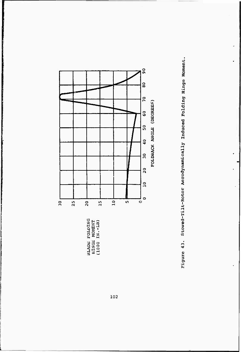
o en
o
o
o
o in
o
o
o r-4
u
Q
o in o m in
+> C
c BC
tn c •H -a H o
»o 0) ü 3 -0 C H
U
| c >1 •o o
%
u o 4J 0 « I
•p
S w ^ 3 Q '
sis M «4 I-I
•H En I
"0 0) > 0 +J
3
•H
102
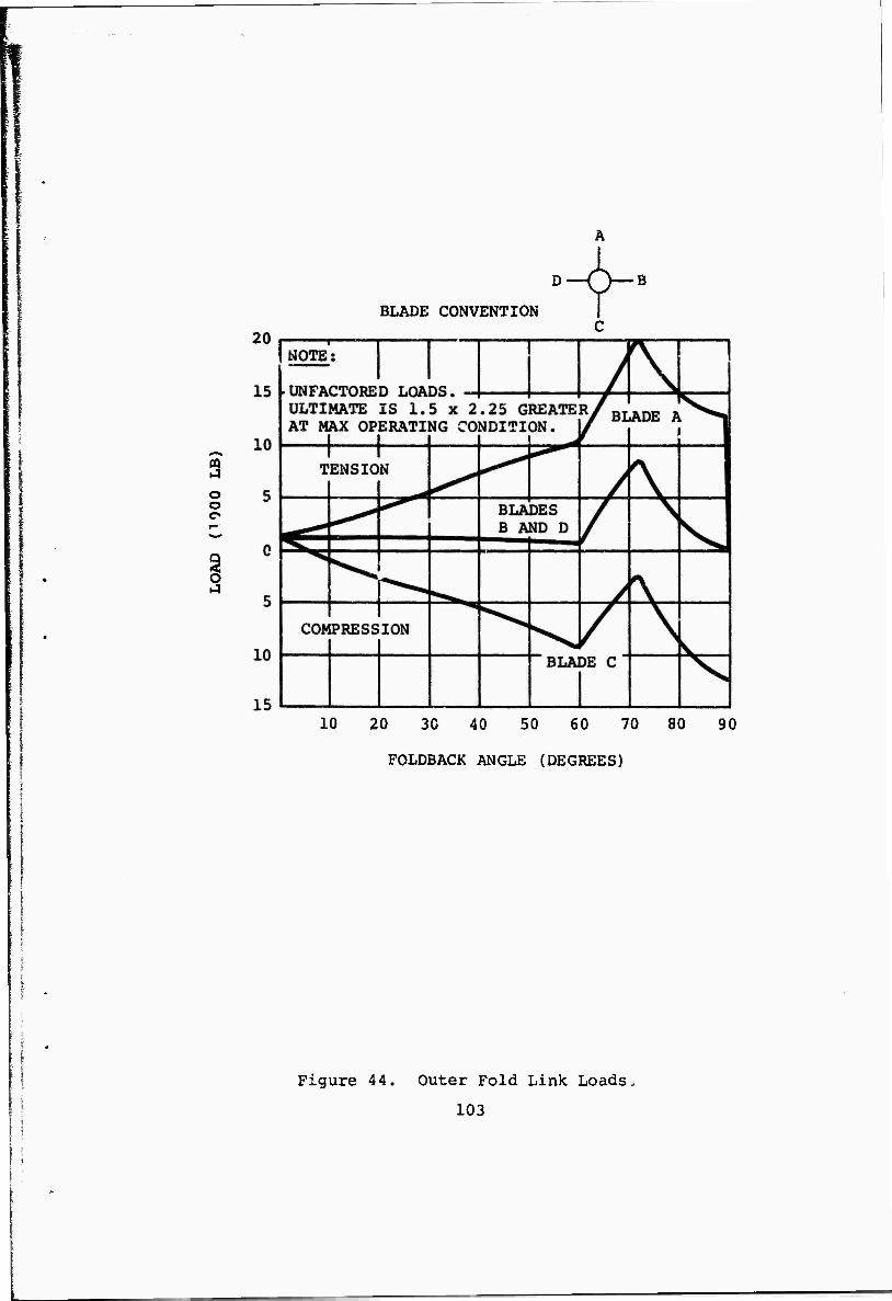
3 o o
BLADE CONVENTION | C
10 20 30 40 50 60 70 80 90
FOLDBACK ANGLE (DEGREES)
Figure 44. Outer Fold Link Loads.
103
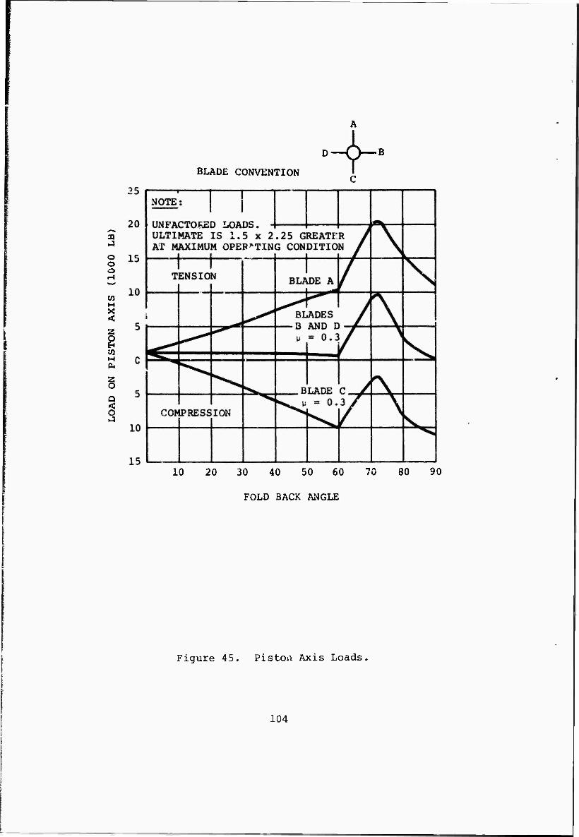
BLADE CONVENTION
A
r""
a .4
o o o
en
<
z o EH
H (X
§ Q < O
B
10 20 30 40 50 60 /Ü 80 90
FOLD BACK ANGLE
Figure 45. Piston Axis Loads,
104
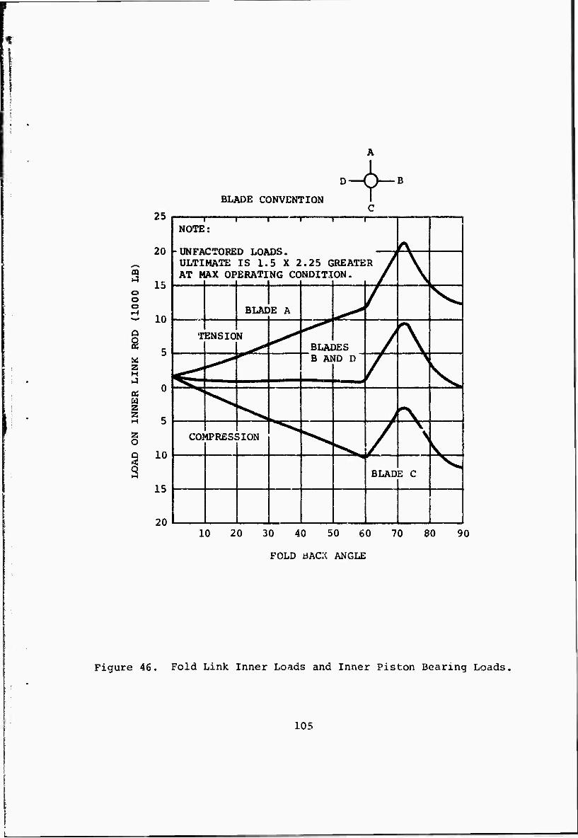
B
BLADE CONVENTION
CQ
O o o
2 O G <
25
20 -
15
- 10
H
w 2 2 H 5
10
15
20
1 1 1 1 1 ! NOTE:
L tifciwiionvNTVPr» T ^\»rtt* f\ ÜLTI AT i
MATE IS 1.5 X 2.25 CREATE AX OPERATING CONDITION,
i i i i V \
BLADE A / V^
T ENS 10 N BLAI DES / \
^ ^
B At iD D
/
\ k CO] dPRESi ;ION ^ 7 v
BLAD 3 C V
10 20 30 40 50 60 70 80 90
FOLD ÜACK ANGLE
Figure 46. Fold Link Inner Loads and Inner Piston Bearing Loads,
105
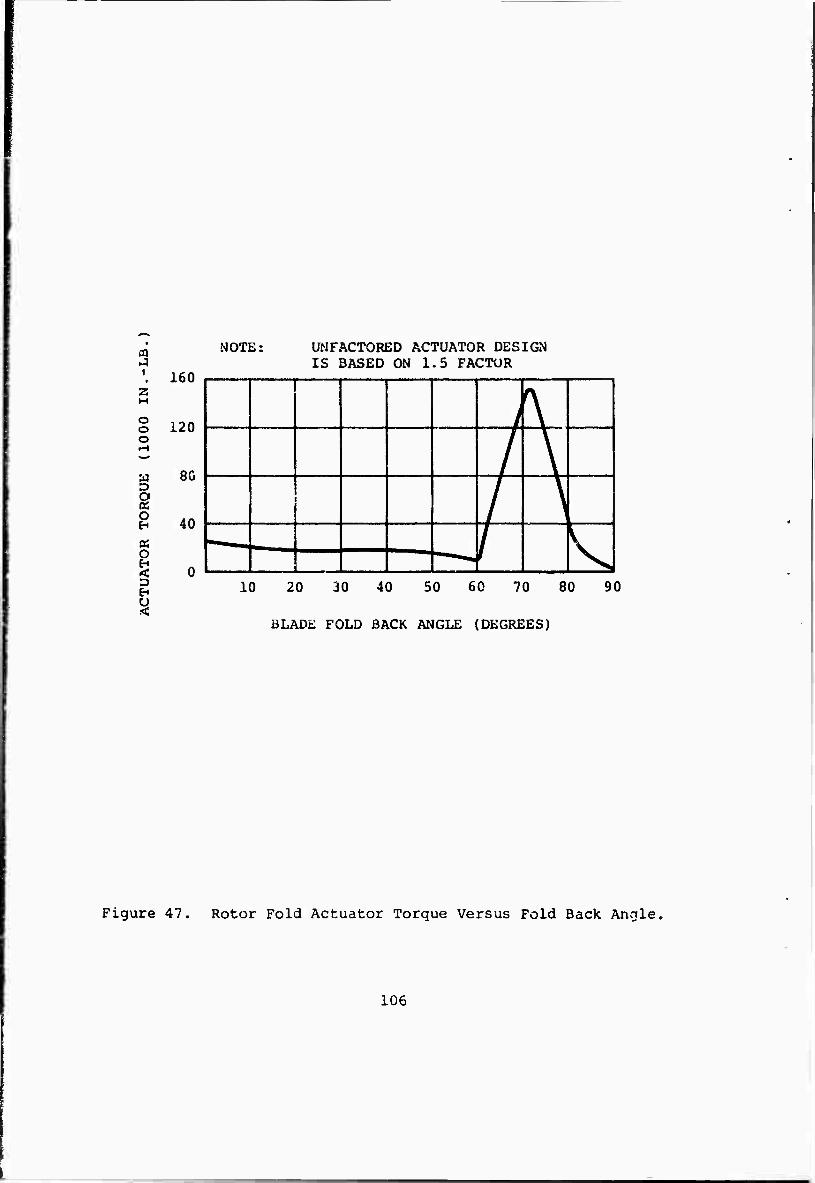
m i
z H
O O O
a D O (K O
« O EH <
E-i U .<
160
120
8G
40
NOTE: UNFACTORED ACTUATOR DESIGN IS BASED ON 1.5 FACTOR
10 20 30 40 50 60 70 80
BLADE FOLD BACK ANGLE (DEGREES)
90
Figure 47. Rotor Fold Actuator Torque Versus Fold Back Angle,
106
This bearing assembly will give a total system life of 1000 hours using present day materials. Use of materials expected to be available in the 1975 time period would increase the lira from iüuü to 1750
I hours.
I b. Blade Retention Bearing
I Analysis of the blade retention bearing gives the | following results:
i
I i
Bearing "A" Bearing "B"
(Inboard Bearing) (Outboard Bearing)
Ball Diameter 1.625" Wall Thickness)
(Hollow 0.15" 0.5"
No. of Balls 21 48
Preload 40,000 Lbs. 40,000 Lbs.
I,.- Life 500 Hours *
*This bearing is substantially unloaded giving a total retention bearing system life in excess of 500 hours.
The above information pertains to present day materials; use of 1975 time frame materials will give an expected life for Bearing "A" of 800 hours. In addition, it is noted that hollow balls cannot be assessed accurately by current computer programs. Hollow balls are expected to be superior to solid balls because lower contact stresses are expected in the hollow balls due to their greater compliancy. Therefore, the preceding analysis is considered to be conservative, and the bearing depicted in Figure 41 may be considered ade- quate for its purpose.
7. STIFFNESS AND DEFLECTIONS
Within the scope of this study and in the absence of a j detailed dynamic analysis of the rotor, it was not possible
to determine whether the desired stiffness criteria had been achieved with the arrangement shown in Figure 41. It is recognized, however, that special attention should be given to such areas as the blade fold locking pins, the swashplate assembly, the pitch change sleeve jaw clutches, and the blade fold mechanism components. Future testing and analysis will establish the stiffness and deflection criteria.
107
8. CONCLUSIONS AND RECOMMENDATIONS
From the work completed in the study to date the following conclusions and recommendations are made:
a. It is possible to design a workable rotor hub assembly for a folding tilt rotor aircraft, within acceptable weight limits and having all the desired features, without undue complexity.
b. A hingeless rotor does not present insoluble problems within the envelope of the nacelle size (diameter), but further work is required to establish a complete load spectrum and stress analysis for the principal components.
c. A complete study is recommended of the dynamic behavior cf the rotor system during folding and unfold- ing operations to obviate any possible dynamic instabilities and to establish stiffness criteria for the hub and fold mechani'ra.
d. A detailed investigation should be undertaken to determine the need for the addition of lateral cyclic control for load alleviation during gusts or maneuvers.
108
SECTION VII
DRIVE SYSTEM
1. DRIVE SYSTEM OBJECTIVES
a. Basic Objectives;
The drive system shall transmit power from the engine to the fans or rotors using a design of minimum weight consistent with the requirement for the absence of undesirable restrictions or limitations on the ability of the vehicle to fulfill its intended mission. In addition, the drive system, including the lubrication, cooling, and accessory drives, shall be designed to meet the load, life, and aircraft performance parameters specified in the applicable detail specifications.
b. Detail Objectives
(1) The interaction between drive system and other aircraft systems shall not result in unacceptable dynamic characteristics.
(2) Design flexibility shall be maintained to permit future transmission growth without affecting interchangeability.
(3) The number of critical components shall be kept to the practical minimum through the use of re- dundant components, multiple load paths, etc.
(4) The inclusion of fail-safe design philosophy is mandatory for all critical components.
(5) Failure warning devices shall be incorporated for all critical single or multiple load path compo- nents. After a warning occurs, there shall be a minimum of 30 minutes of flight before a catastro- phic condition is encountered.
(6) The drive system shall be designed so that a single failure of a noncritical component shall not precipitate other failures.
(7) The drive system shall accomplish its (specifica- tion) tasks including maintaining the proper mission reliability for the life of the vehicle.
109
(8) The drive system shall exhibit suitable combat survivability by the use of inherent shielding from adjacent structure where applicable,
(9) The operational costs shall be held to a minimum by consideration in early design phases, and shall include such items as high reliability to minimize spares, commonality of parts to minimize inventory, and maximum ruggedness to minimize handling damage.
(10) The maintainability objectives shall be met by consideration in early design phases and shall include provision of integral workstands in related structure.
(11) The drive system components shall be designed with proper emphasis on producibility to keep costs as low as possible within the total system function, safety, reliability, maintainability and surviv- ability goals as outlined in the above, waile maintaining realistic cost and time schedules.
(12) The gear cases shall be deflection-analyzed and development-tested to assure compliance with deflection criteria when applicable.
(13) The lubrication systems shall be designed to meet the double requirement of operating in vertical mode and horizontal mode. All lubrication piping, pumps, sumps, filters, and coolers shall be de- signed to adequately meet this requirement.
(14) Provision shall be made to condition-monitor sub- system components. Information made available from this system shall be fed into ground-based computers at periodic intervals for automatic evaluation of component soundness. The pilot shall also be provided with audio warning means.
DESIGN CRITERIA
The torque capabilities ol the rotor transmission system shall meet the most severe of the following requirements:
a. Hover at design takeoff gross weight at the altitude and temperature appropriate to the mission, out of ground effect, with the thrust required for download, control and 500 fpm rate of climb. The control applied shall give the most severe powf.r absorption occasioned by 100 percent control about jne axis and 50 percent about the other two axis. This is to be construed as
110
- '-
a total power requirement. Shafts will be sized for full torque due to 100 percent yaw control. A 55-45 power split shall be used for gear sizing, the full yaw control case being considered a transient condition.
b. A climb rate of 1,500 fpm at 200 knots EAS, SL standard day.
c. A level flight speed of 250 Icnots EAS, SL standard day. The rotor transmission components shall also be de- signed to the torque appropriate to one shaft engine failed conditions for the above cases.
The shafting shall be designed to take the torques imposed by maximum SL standard day static power of all engines on one side with all engines failed on the other side. This shall not be applied as a design case for gearing.
The fan drive system shall be designed to take maximum SL standard day static power.
3. DRIVE SYSTEM DESIGN
a> General
A general arrangement drawing is shown in Figure 48. The drive system provides the mechanical transfer of power from the twinned engines to the lifting rotors or to the cruise fans. This can be accomplished by the engine box in any required split of power during the various lases of flight. The engine box combines and distributes the power to a common cruise fan and/or thu rotor transmission system. A set of synchronized jaw clutches are used to selectively tie each load into the power path. The jaw clutches are engaged after the electrical synchronizer signals show proper speed differential. The fan speedup prior to engagement is accomplished by modulating the variable inlet and exit guide vanes to control torque and speed of the wind- milling fan. Other means include variable pitch fans in conjunction with direct drive (no clutch). While the studies to date have assumed the fan clutch/guide
| vane system and these are implicit in the weights I statement, the latter system is promising and should | be considered in future studies. At the proper speed \ differential point the jaw clutch is engaged and the
guide vanes are readjusted to load the fan to any desired amount of power-thrust. In a similar manner power is applied through the rotor clutch; here, how- ever, the rotor prespin or windmilling action is con- trolled by adjusting collective pitch. Rotor synchroni- zation and power transfer are insured by the cross-shaft
111
system containing mid-wing-mounted cross-shaft bevel boxes connecting engine combining boxes with the cross- shaft and cross-shaft tip bevel boxes connecting rotor transmissions to the cross-shaft. Each rotor trans- mission is wing tip, nacelle-mounted and contains its own lubrication, cooling system, accessory drives, rotor brake, stopping, and indexing means.
(1) Design and Materials
The design of the drive system was approached with proper emphasis on meeting all applicable design objectives and criteria as previously outlined. In addition, consideration was given to the use of the most recent aerospace materials and tech- niques such as advanced steels, vacuum melt bear- ing steel, the use of titanium shafts and gear backup structures and the use of electron beam welding,
(2) Shafting (Reference Figure 48)
The drive shafts are all designed to be operated at high speed to minimize the weight. A prelimin- ary decision was mad*1 to consider the cross-shaft as supercritical and the longitudinal shafts (through nacelles) and drop shafts (engine box to wing box) to be subcritical. Supercritical shaft- ing is provided with single dampers per span located near one end.
(3"( Couplings and Wing Deflection
The shaft couplings on all subcriticai shafts in nacelle and from engine box to cross-shaft bevel box i»re subjected to relatively low deflections and typical flexure plar.e couplings seem adequate for this task. The supercritical cross-shaft, through the wing, subjects the end couplings to a number of more severe deflections, (Figure 49). At stations 148 and 337 a 2-1/2 degree coupling is provided to allow the shaft to "curve" forward as shown on Figure 48. The normal one IG wing deflection causes angular deflection at the center coupling and at the couplings at station 122 of approximately one-quarter (1/4) degree. This would seem satisfactory for typical flexure plate couplings. The coupling at station 235 is sub- jected to a l£irger deflection of approximately one-half (1/2) degree. This deflection is high enough to require another type of coupling, pos- sibly a diaphragm type or twin flexure plate type.
112
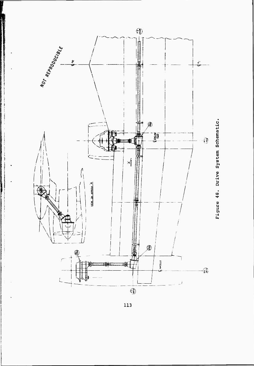
I
ü ■M ■P SO
XI O W
§ ■P (0 >1 m
>
D
00
0)
fa
113
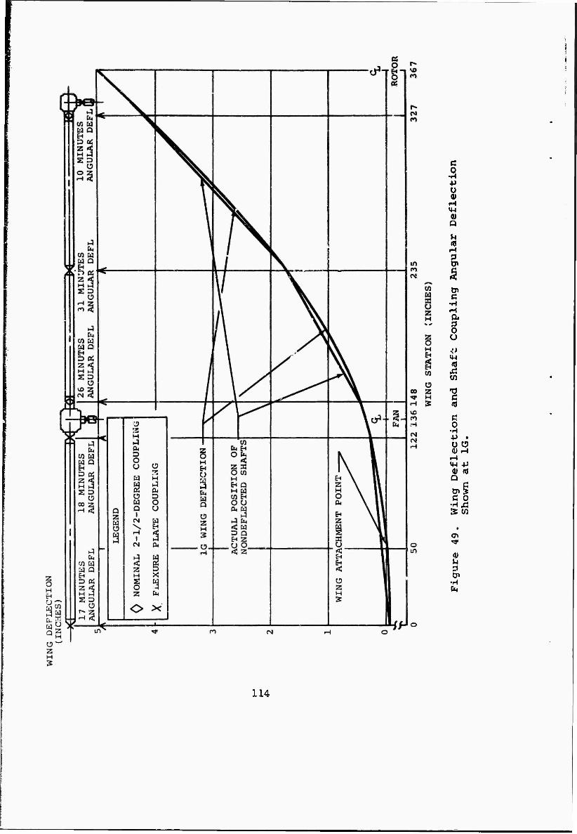
c o ■ri ■P o 9)
f~i IM Q) Q
U tii
c •H rH
O U
id
en
-o c «j
ß o •H
Ü u (U H H 4-1 -P (U n» Q
c o 3: (A
0)
■H
114
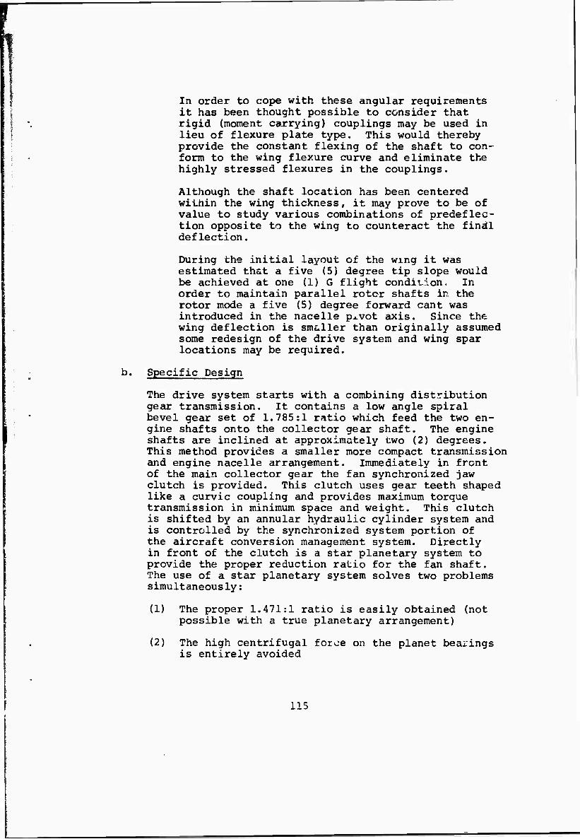
In order to cope with these angular requirements it has been thought possible to consider that rigid (moment carrying) couplings may be used in lieu of flexure plate type. This would thereby provide the constant flexing of the shaft to con- form to the wing flexure curve and eliminate the highly stressed flexures in the couplings.
Although the shaft location has been centered within the wing thickness, it may prove to be of value to study various combinations of predeflec- tion opposite to the wing to counteract the final deflection.
During the initial layout of the wmg it was estimated that a five (5) degree tip slope would be achieved at one (1) G flight condition. In order to maintain parallel rotor shafts in the rotor mode a five (5) degree forward cant was introduced in the nacelle p^vot axis. Since the wing deflection is smeller than originally assumed some redesign of the drive system and wing spar locations may be required.
b. Specific Design
The drive system starts with a combining distribution gear transmission. It contains a low angle spiral bevel gear set of 1.785:1 ratio which feed the two en- gine shafts onto the collector gear shaft. The engine shafts are inclined at approximately two (2) degrees. This method provides a smaller more compact transmission and engine nacelle arrangement. Immediately in front of the main collector gear the fan synchronized jaw clutch is provided. This clutch uses gear teeth shaped like a curvic coupling and provides maximum torque transmission in minimum space and weight. This clutch is shifted by an annular hydraulic cylinder system and is controlled by the synchronized system portion of the aircraft conversion management system. Directly in front of the clutch is a star planetary system to provide the proper reduction ratio for the fan shaft. The use of a star planetary system solves two problems simultaneously:
(1) The proper 1.471:1 ratio is easily obtained (not possible with a true planetary arrangement)
(2) The high centrifugal force on the planet bearings is entirely avoided
115
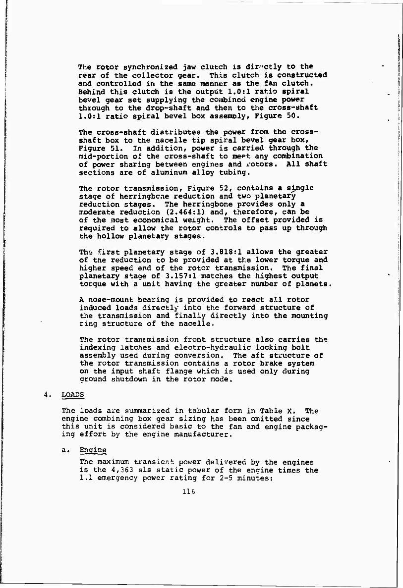
The rotor synchronized jaw clutch is directly to the rear of the collector gear. This clutch is constructed and controlled in the sane manner as the fan clutch. Behind this clutch is the output 1.0:1 ratio spiral bevel gear set supplying the coiabined engine power thxough to the drop-shaft and then to the cross-shaft 1.0:1 ratio spiral bevel box assembly, Figure 50.
The cross-shaft distributes the power from the cross- shaft box to the nacelle tip spiral bevel gear box. Figure 51. In addition, power is carried through the mid-portion of the cross-shaft to inept any combination of power sharing between engines and rotors. All shaft sections are of aluminum alloy tubing.
The rotor transmission. Figure 52, contains a single stage of herringbone reduction and two planetary reduction stages. The herringbone provides only a moderate reduction (2.464:1) and, therefore, can be of the most economical weight. The offset provided is required to allow the rotor controls to pass up through the hollow planetary stages.
ThCä first planetary stage of 3.818:1 allows the greater of tne reduction to be provided at the lower torque and higher speed end of the rotor transmission. The final planetary stage of 3.157:1 matches the highest output torque with a unit having the greater number of planets.
A nose-mount bearing is provided to react all rotor induced loads directly into the forward structure of the transmission and finally directly into the mounting ring structure of the nacelle.
The rotor transmission front structure also carries th«5 indexing latches and electro-hydraulic locking bolt assembly used during conversion. The aft structure of the rotor transmission contains a rotor brake system on the input shaft flange which is used only during ground shutdown in the rotor mode.
4. LOADS
The loads are summarized in tabular form in Table X. The engine combining box gear sizing has been omitted since this unit is considered basic to the fan and engine packag- ing effort by the engine manufacturer.
a. Engine
The maximum transient power delivered by the engines is the 4,363 sis static power of the engine times the 1.1 emergency power rating for 2-5 minutes:
116
o
o to X o ff.
u «J Q) Ü
4J <M (0
(0
CO n o u u
o in
*H 3 D»
•H h
117
4J
Xi
&
I u (0
s
in
0)
•H
118
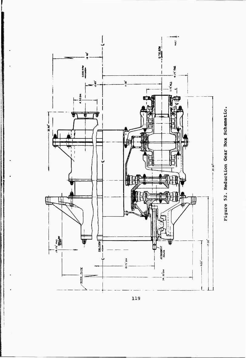
u
o (A
X 0
M
C 0
•H 4J Ü 3
^
CM
119
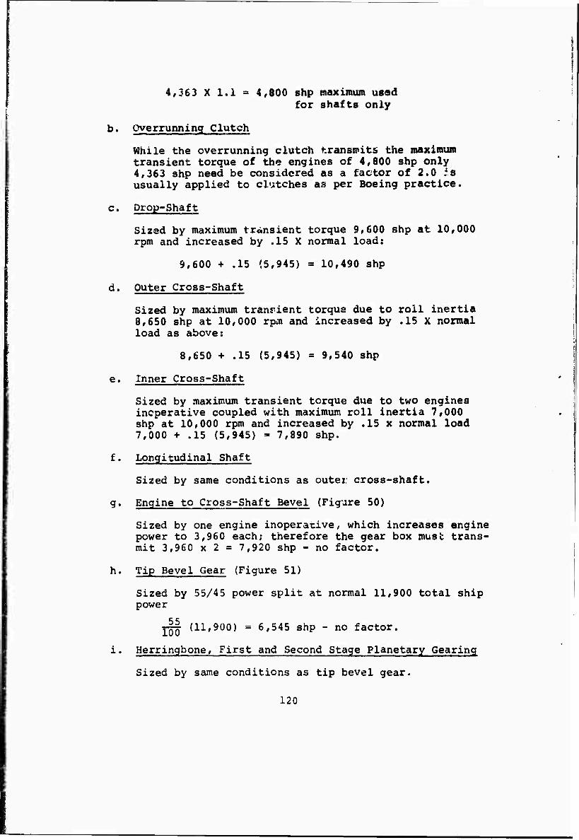
4,363 X 1.1 s 4,800 shp tnaximum used for shafts only
b. overrunning Clutch
While the overrunning clutch transmits the maximum transient torque of the engines of 4,800 shp only 4,363 shp need be considered as a factor of 2.0 is usually applied to clutches aa per Boeing practice.
c. Drop-Shaft
Sized by maximum transient torque 9,600 shp at 10,000 rpm and increased by .15 X normal load:
9,600 + .15 (5,945) » 10,490 shp
d. Outer Cross-Shaft
Sized by maximum transient torque due to roll inertia 8,650 shp at 10,000 rpm and increased by .15 X normal load as above:
8,650 + .15 (5,945) = 9,540 shp
e. Inner Cross-Shaft
Sized by maximum transient torque due to two engines inoperative coupled with maximum roll inertia 7,000 shp at 10,000 rpm and increased by .15 x normal load 7,000 + .15 (5,945) = 7,890 shp.
f. Longitudinal Shaft
Sized by same conditions as outer cross-shaft.
g. Engine to Cross-Shaft Bevel (Figure 50)
Sized by one engine inoperative, which increases engine power to 3,960 each; therefore the gear box must trans- mit 3,960 x 2 = 7,920 shp - no factor.
h. Tip Bevel Gear (Figure 51)
Sized by 55/45 power split at normal 11,900 total ship power
Y|| (11,900) = 6,545 shp - no factor.
i« Herringbone, First and Second Stage Planetary Gearing
Sized by same conditions as tip bevel gear.
120
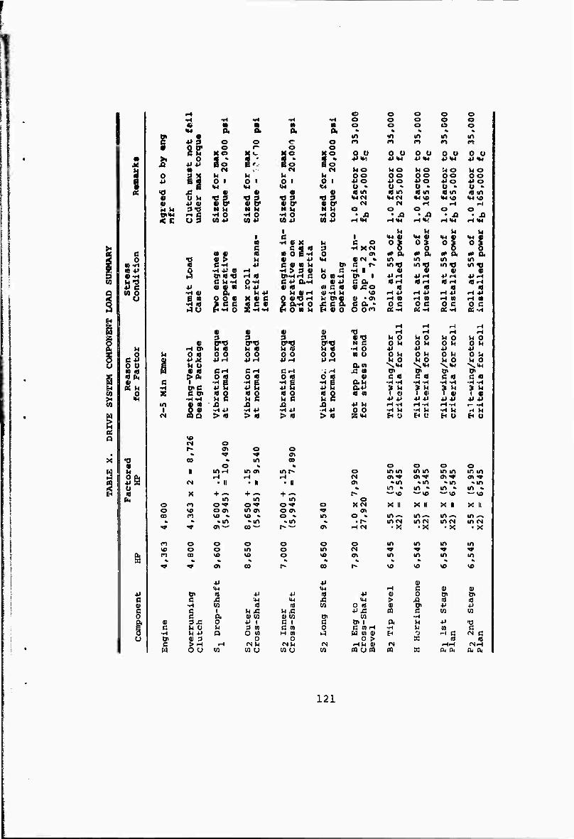
i I
•-I o o o o O ■»« -* ^1 •H •H o o o o O « m « M M o o o o o «4 a a a a * « «
9 • in vn in in in 6 ♦» 9 o o c o rt M f* «n «n 8 gg" o
KO r- o „ o
o O 0 o o 0 Ü 0 U o u ■ >, 0 So 9 ' s * a % VIM *»<w PIM P<M P<M M S *>*> E '.- So 6 o ■ N v" M «M MO uo MO MO MO 3 o n M h M u OO OO OO OO OO B 41 O 1 0 i 0 1 o 1 PO PO PO PO 4JO 0 i «H •H IM <C4 Ü » o * o • 0 » O « 05 <o A • • • • «tn «m «in • in «in
« O »1 •gg. Ig. « 3 « 3 IHM »MM *4VO «M VO •M vo • p • • CP 4» tr CM M •-« ■H H
s.^ s-o N U N M N 14 N u o O o O o
ö§ •H O •H O ^ 0 •H o • -Q • JQ • JQ • J3 • A < c to *J «1 P CO P (0P rHIM .HIM -UK HIM HIM
1 U M M M 1 e | IM 4) IM 4) IM 4> IM 4) a •H « X M c o 0 | 0 | 0 | o i
>• % C fij
«oe id 3 ■H XN
C « « •H 0 OV *> a «P a OP a * a 2 0 •0 « > u 4) P IM 4(<N » m m in m 5 « •H « C-H ■p C 41 N M tr c r* mtj iffO m TJ m »o 5S «41 s •riÜ 9 <H •H > 3 4) u e •H I 4) 4) 4) « w «•H XJiffO H « CP-Wr-i ß o «•H tn i PfH p-l PH PH (0 Ö ■3 C UM O-H CP a-H 4)P c a «rt «FH «H «H
e ♦» •S." Vl-P « « m C « 4) .CO « « « « Q (0 O •H « MP H «•-) •U-H n VO rtP r^ P «H P H P J2 o 53 0 o « X « C O ««>H *< ?& 4> -OV ■H « H n r-l M H M Ö ice « C « » a-H 0 JC c a * 0 C 0 e 0 C o C « i40 flTi o ti o « U H 0! O O 0" «•H «•H ai-H fa-H
g iH H •H H « 41 4) 4) T> r^ H H H
iSS 3 3 3 3 4»T> VI 0 M 0 M 0 M 0 g «1 CO «TTJ 0"0 0"0 N C 0 u O U 0 M 0 M
w r-t 0« M « h « M « U « •H 0 ■H P P P
§ o M o «I o o 0 O 0 O 0 0 « Ü 0 u 0 M 0 M 0 U C-P 9 •M^ ■Mi-t ■PrH +IH PFH u 0 U 0 M O U 0
o 0 0 1 U 0 am N.<M \«H \«M X"M m «1 M « « Cr-I ßi-t CH 4 H £ a tn tJ> tn OV « fa >fa 0 « 0 id 0 « 0 id 4) C « C «8 c « C «
£u C •H
1 sg 3g ^a •H P g au •rl-rl
» u •H-H » M
-H -H 3 M
•H -H » U
M o i C «J> id o ■d o « o a 0 a n 1 O 1 4) 1 41 1 4) X >H -HH4 h c u c u c u S PP PP P P P P (Q m « n A X) XI JQ P u iH^I H-H iH -H ■- -H 5 « •H*J •H4i •H.P -HP 0 0 •H M •H U •H M H M g N no > <d > « > • > id Z<M t* y t* Ü H U H Ü
« a «0
o 0\ O o • •9 ^ »
X •0 CO k in C9 4) o % * o o o O
s M II IOf-1 mov m r~ o m in tn m m m in m O a iH H H fM ov«» ov^c OV-* ov •v
9 +» <s • II • II • ii <J> «in «m «m «m U % in «• m « m « m « is id fa
X in
+ — in in o
*-vo •—»o ww «- VO
o n O'» O'» o* o XCM X II X 11 X II X II o vo oo> m o\ O OV •>» OV CO n vo « vo » o » in o » inx> m^. in-% m -» % % »tn ••m • m » • r» m M IrtM m M m M ^f •* o»^- CO — r--' CTl ■-I IN •X • X • X • X
»n o o o o O O in in m m «« o o in o m <N •* ■v >w •*"
s fo 00 vo vo o VO OV m m m m % % % « <» % % « « « « ^ I1
•P 4-1
CO r- 00
p
r- VO
H
vo
HI ß
VO
ID
VO
0) +i CJi id p P 10 P 4) 0 cn o» c ß Ä ■■M <M £ IM > A a 10 01 •H en id id w 0 id a> Os P p ß c i M J5 U ,C P.C n a en en 0 ß a a» en <0 VI Cn en •H & 0) Sä 0 P i C 1 a tn i a u P ■ü
% c M Ü M P w d m 0 C »H •H u to ß
•H U *i a O M H 0) ^ a vi u B 0 H C (N C u 0i 1) 3 o 0 o > X 10 id
c >^ iH NU OIH CN HU t) <N ■HH MrH H OO M w u M U w PQ urn m X fa fa 04 a,
121
STRESS ANALYSIS
The drive system stress analysis and sizinc of components was nade using current stress allowables and materials in order to establish a firm baseline design.
The weight analysis of this baseline was then modified using reduction factors projected for technology appropriate to a 1976 IOC date.
a. Allowable stresses used in the sizing of shafting for this analysis are:
20,000 "si design allowable 2024-T3 aluminum alloy tubing t _ 02_
Both of these values agree with successful designs as used in Boeing-Vertol helicopters.
Sample Calculations
Outer cross-shaft 8,650 shp
T.i^|^0) = 54,500 in.-ib
Steady state cross-shaft transient torque
_ .15 63,025 (5,945) K ,,, .„ ,. T = 10,060 — ' 5'625 in-"lb
54,500 + 5,625 » 60,125 in.-lb
Assume 4-1/2 in. OD tube 4.5 (.027) » .122
R4 - r4 4 j . n «—j-JL. . 7.86 in.
_ Tr 60,125(2.25) ,, -rtrt ,.
b. Allowable stress used in the sizing of spiral buvel gears for this analysis are:
35,000 psi Bending - f.
225,000 psi Hertz - f
Sample Calculations
Tip spiral bevel gearbox ^Figure 51). 6,545 shp
122
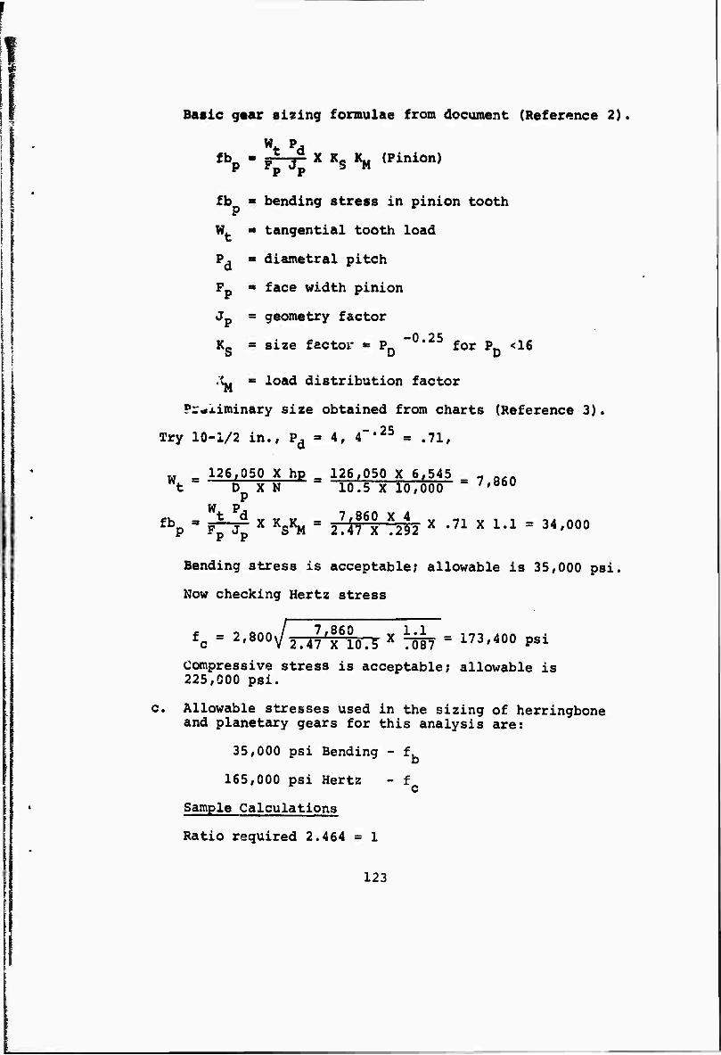
Basic gear sizing formulae from document (Reference 2).
Wtpd fb - fr-j^ X Ks 1^ (Pinion)
fb <■ bending stress in pinion tooth
wt IB tangential tooth load
pd « diametral ] pitch
pp SS face width pinion
Jp = geometry factor -0 25 Kg ■ size factor « P * for PD <16
X. = load distribution factor
Preliminary size obtained from charts (Reference 3).
Try 10-1/2 in., Pd = 4, 4"•25 = .71,
w - 126,050 X hp 126,050 X 6,545 - a,n *t " D X N " io.5 X 10,000 ' /'060
W P fbp = ppr; X h*U " 27Aiex X292 X -ll X l'1 = 34'000
Bending stress is acceptable; allowable is 35,000 psi.
Now checking Hertz stress
fc - 2Wä.4?,"lo.iritT55T° i"'400 P'i Compressive stress is acceptable; allowable is 225,000 psi.
:. Allowable stresses used in the sizing of herringbone and planetary gears for this analysis are:
35,000 psi Bending - f.
165,000 psi Hertz - f c Sample Calculations
Ratio required 2.464 « 1
123
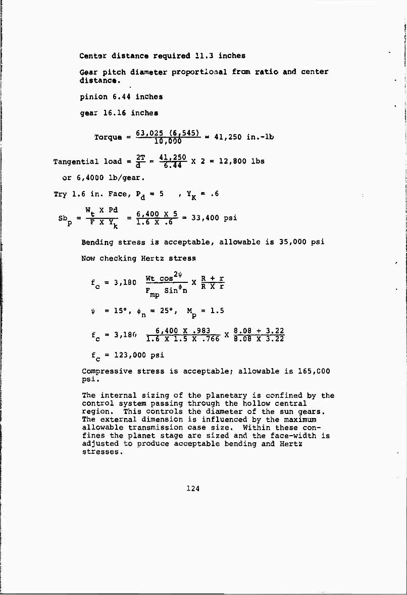
Cantor distance required 11.3 inches
Gear pitch diameter proportional from ratio and center distance.
pinion 6.44 inches
gear 16.16 inches
Torque = 63'0i6,^i545) « 41.250 in.-lb
Tangential load = g^ = ^fH^ X 2 - 12,800 lbs
or 6,4000 lb/gear.
Try 1.6 in. Face, pd ^ ^ ' YK "" *6
*p - "4^ - 'iffit ' ",400 psi
Bending stress is acceptable, allowable is 35,000 psi
Now checking Hertz stress
f =3,i8o wtc°s2! xJHrl FmpSinn
* = 15°, A = 25°, M = 1.5
f -i ,0, 6,400 X .983 „ 8.08 + 3.22 rc " ■,' ö 1.6 X 1.5 X .766 Ä 8.08 X 3.22
f = 123,000 psi c
Compressive stress is acceptable; allowable is 165,000 psi.
The internal sizing of the planetary is confined by the control system passing through the hollow central region. This controls the diameter of the sun gears. The external dimension is influenced by the maximum allowable transmission case size. Within these con- fines the planet stage are sized and the face-width is adjusted to produce acceptable bending and Hertz stresses.
124
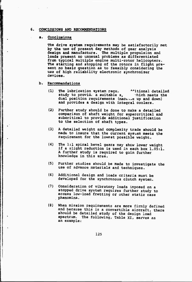
6. CONCLUSIONS AND RECOMMENDATIONS
a. Conciusione
The drive system requirements may be satisfactorily met by the use of present day methods of gear analysis design and manufacture. The multiple propulsion and loads present no unusual problems as differentiated from typical multiple engine multi-rotor helicopters. The starting and stopping of the rotors in flight pre- sent no basic question as to feasibly considering the use of high reliability electronic synchronizer devices.
b. Recommendations
(1) The lubrication system requ* ^itional detailed study to providv a suitable sa -rhich meets the dual position requirements (nact^e up and down) and provides a design with integral coolers.
(2) Further study should be done to make a detailed comparison of shaft weight for supercritical and subcritical to provide additional justification to the selection of shaft types.
(3) A detailed weight and complexity trade should be made to insure that the current sysvem meets the requirement for the lowest possible weight.
(4) The 1:1 spiral bevel gears may shew lower weight if a slight reduction is used in each box 1.05:1. A further study is required to gain further knowledge in this area.
(5) Further studies should be made to investigate the use of advance materials and techniques.
(6) Additional design and loads criteria must be developed for the synchronous clutch system.
(7) Consideration of vibratory loads imposed on a stopped drive system requires further study to access low-load fretting or other static case phenomina.
(8) When mission requirements are more firmly defined and because this is a convertible aircraft, there should be detailed study of the design load spectrum. The following, Table XI, serves as an examplei
125
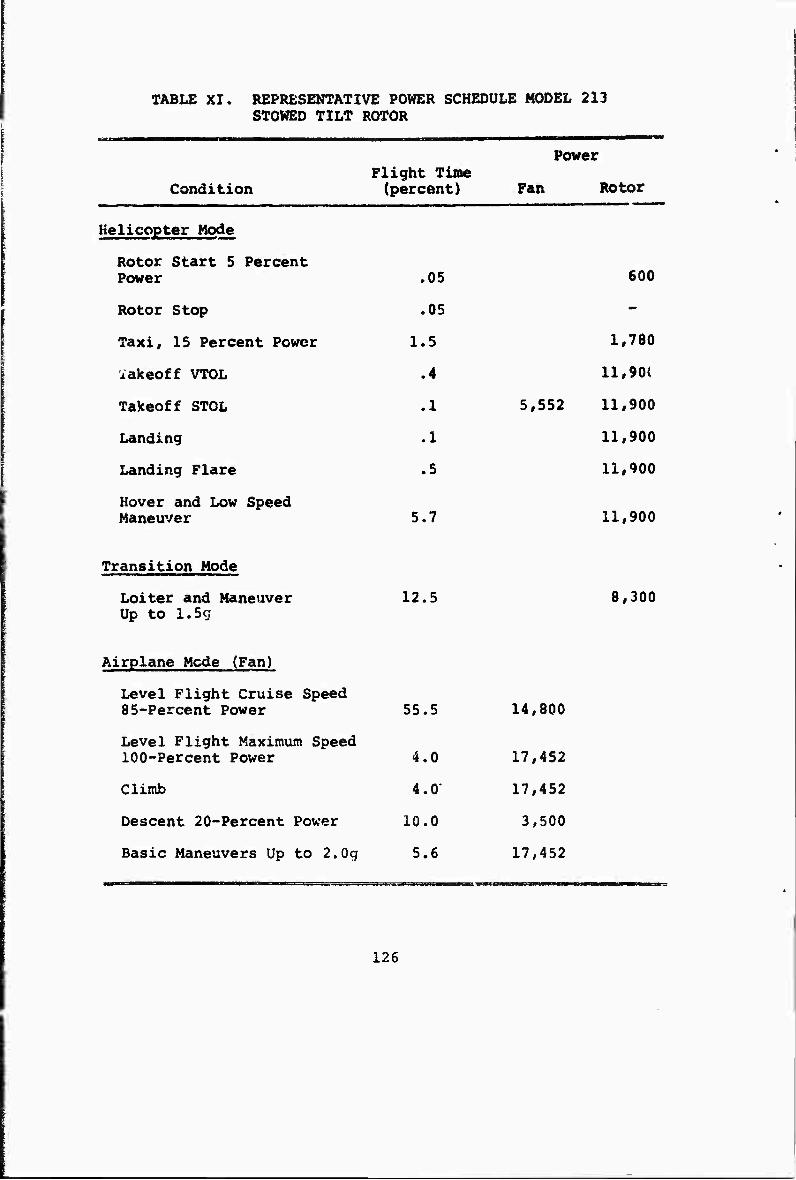
TABLE XI. REPRESENTATIVE POWER SCHEDULE MODEL 213 STOWED TILT ROTOR
Condition Flight Tine (percent)
Power
Fan Rotor
Helicopter Mode
Rotor Start 5 Percent Power .05
Rotor Stop .05
Taxi, 15 Percent Power 1.5
iakeoff VTOL .4
Takeoff STOL .1
Landing .1
Landing Flare .5
Hover and Low Speed Maneuver 5.7
Transition Mode
Loiter and Maneuver Up to 1.5c;
12.5
5,552
600
1,780
11,90{
11,900
11,900
11,900
11,900
8,300
Airplane Mode (Fan)
Level Flight Cruise Speed 85-Percent Power 55.5
Level Flight Maximum Speed 100-Percent Power 4.0
Climb 4.0'
Descent 20-Percent Power 10.0
Basic Maneuvers Up to 2.0g 5.6
14,800
17,452
17,452
3,500
17,452
126
SECTION VIII
ROTOR NACELLE AND TILTING MECHANISM
1. OBJECTIVE
The objective of the nacelle design study Is to provide a nacelle structure configured to provide attachment, clearance, and support for the following:
a. The rotor drive system, Including the wing-tip bevel box, the rotor drive shafting, support bearings, and main transmission.
b. The rotor hub and its accessories (e.g., the rotor fold and stop mechanisms).
c. Nacelle tilt actuators to enable rotation of the nacelle and provide for transition from forward aircraft flight to rearward helicopter flight.
d. Rotor hub controls.
e. Oil cooling provisions.
f. Folded rotor blade retention devices.
The rotor nacelle shall provide a minimum drag envelope around which the rotor blades may be folded. It shall provide an adequate enclosure for the items listed above and be of the smallest possible cross section and volume consistent with good structural and aerodynamic design practices. The nacelle structure shall incorporate access doors and work platforms to assist in the servicing and maintenance of the nacelle-mounted components.
2. DESIGN
Design constraints on the wing-tip mounted nacelle include the number, length, and chord of blades, wing-tip thick- ness, tilting angle of rotor, and blade foldina method.
Three, four, and five blade rotors were considered, with four blades generally requiring the smallest nacelle diameter.
The four 23-inch chord blades, disposed at 90-degree inter- vals at the hub, are folded back and wrapped flat against the nacelle body in a helical fashion following the twist
127
of the blades. The blades alternately contact the nacelle body on their cambered and uncambered side (i.e., top or bottom surface) in order to provide a space for continua- tion of the wing box structure into the nacelle while maintaining a minimum nacelle cross section.
The original 16-percent wing required a 48-inch minimum diameter nacelle? however, the 20-percent thick wing now specified requires a 55-inch minimum diameter to provide adequate clearance for the thicker wing tip.
The rotor hub plane is located 115 inches forward of the pivot. The overall nacelle length of approximately 34 feet is based on a body of rotation using the static droop deflection shape of the blades from hub to aft end of blades with a 55-inch maximum diameter over the wing and minimum clearance between blades at the aft end. The spinner and tail cone are faired shapes.
Alternate nacelle contours such as plain cylindrical shapes or coke bottle shapes are not being considered at this time; however, they have the same minimum diameter at the wing tip and any shape other than that being considered will result in a larger volume and resultant drag increase.
The rotor pivot axis is skewed 5 degrees to tilt the rotor planes outboard when in the helicopter mode. Wing deflec- tion will reduce the nominal outboard tilt when in actual flight. (Figure 53 shows the nacelle configuration and 54 shows the structural arrangement.)
The main rotor transmission and hub is attached to the forward nacelle mounting ring through the nose mount bear- ing, thus relieving the transmission of structural loads due to control moments, thrust, torque, accelerations, and blade folding.
The forward mounting ring is supported by a forged box- shaped structure incorporating cross frames, webs, drive shaft bearing attachments, and an integral cooling fan housing. This tower structure terminates at a pivot fitting as shown in Figure 55.
Rotor thrust or lift loads, side loads, and torque loads are taken through this structure into the two main pillow block bearings on the stub-wing box. Rotor hub pitching moments and acceleration loads due to maneuvers are taken through the upper and lower beams of the tower structure and transferred to or from the rear-mounted actuators. An additional link fitting is provided to attach the lower actuator at a more favorable geometric location.
128
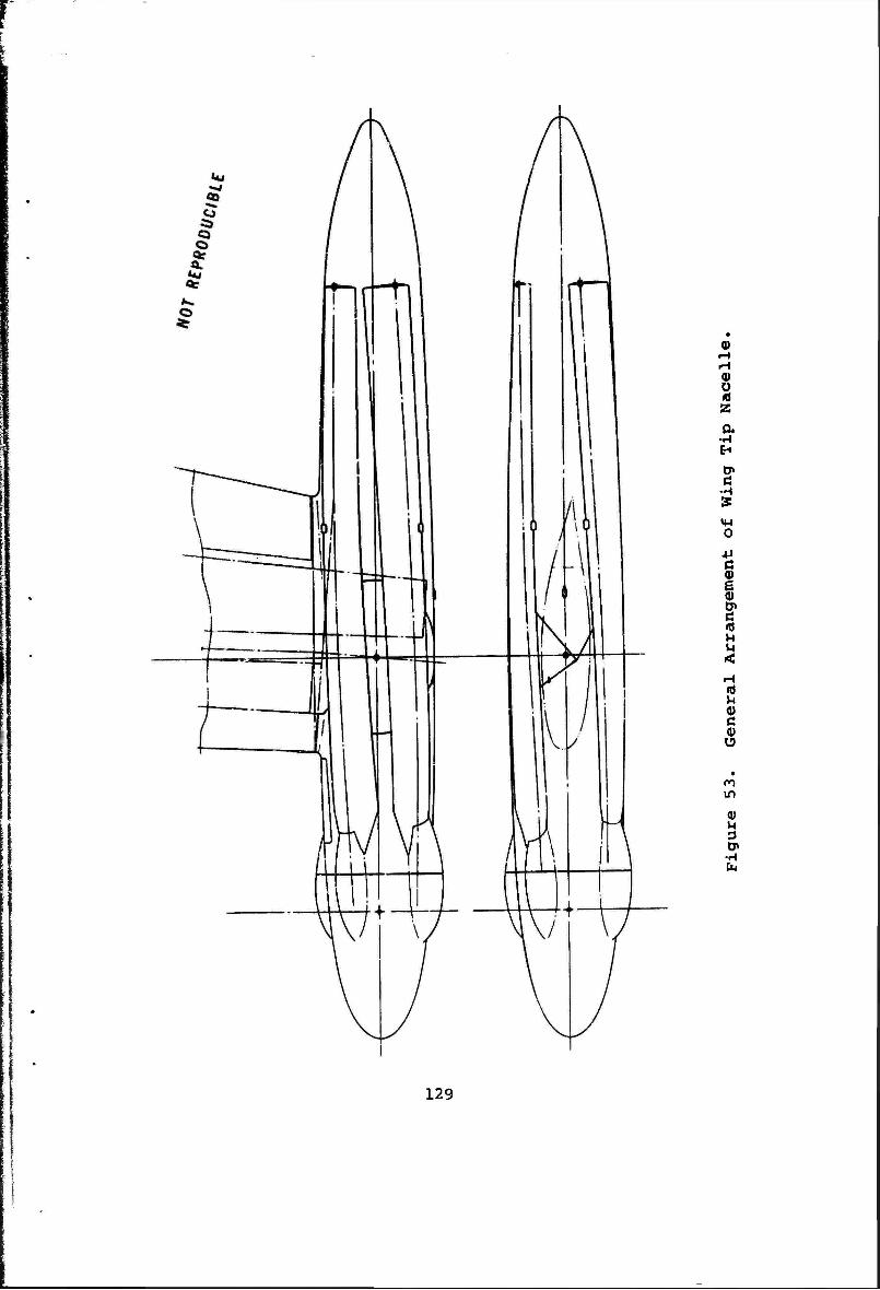
r
<u
8 a a
•H EH
tT> Ö
•H %
O
a>
I ! M M
c
n in
0) M 3
■H
129
I
Since the oil cooling fan only operates with the rotor deployed, its inlets are located under the folded blades and the exhaust exits through openings exposed by deploying the blades or tilting the nacelle.
The forward nacelle skin is considered to be nonstructural. Maintenance and service access for the transmission, drive shaft, rotor brake, and hub control stack is provided for- ward of the wing on the inboard side of the nacelle. This access panel doubles as a work platform.
The nacelle skin is scalloped for the blades and trimmed diagonally through the pivot. The skin has a sliding fairing between the upper blades and a hinged side fairing which clears the fixed nacelle portion when in the heli- copter mode (see Figure 56).
The tilt actuators, first considered to be attached directly to the mounting ring are now aft-mounted. Due to extreme length and stroke required in the forward location, the actuator proportions become impractical; also, their re- actions resulted in fore and aft and vertical loads in the fixed nacelle. The aft mounting will keep actuator reactions essentially parallel and opposite, alraosc a pure couple. This type of load is easily transferred to the wing upper and lower skins through the caps of a heavy closing rib to which the fixed nacelle structure is mounted (see Figure 57). The pitch and acceleration loads on the actuators do not pass through the wing stub.
Hydraulic cylinders were considered for the forward mount- ing but trunnion mounted ball screw jacks are considered more appropriate for the aft-mounted actuators.
The nacelle fairing aft of the actuator attachment is of minimum structure consistent with dynamic and aerodynamic loading. One set of holddown devices is located aft of the pivot to grip the blades and guide them as they are folded back. An additional holddown device at the extreme end of each blade pulls it into intimate contact with the aft part of the nacelle in order to restrain against blade motions due to aerodynamic lift or maneuver accelerations. This system is tentative and the design criteria for blade restraint must await testing of a dynamic model.
Rotor hub and folding controls are routed through the pivot axis into the forward nacelle outboard of the actuator linkage.
A suitable program of blade folding and indexing and rotor nacelle tilting is capable of stowing or deploying the
130
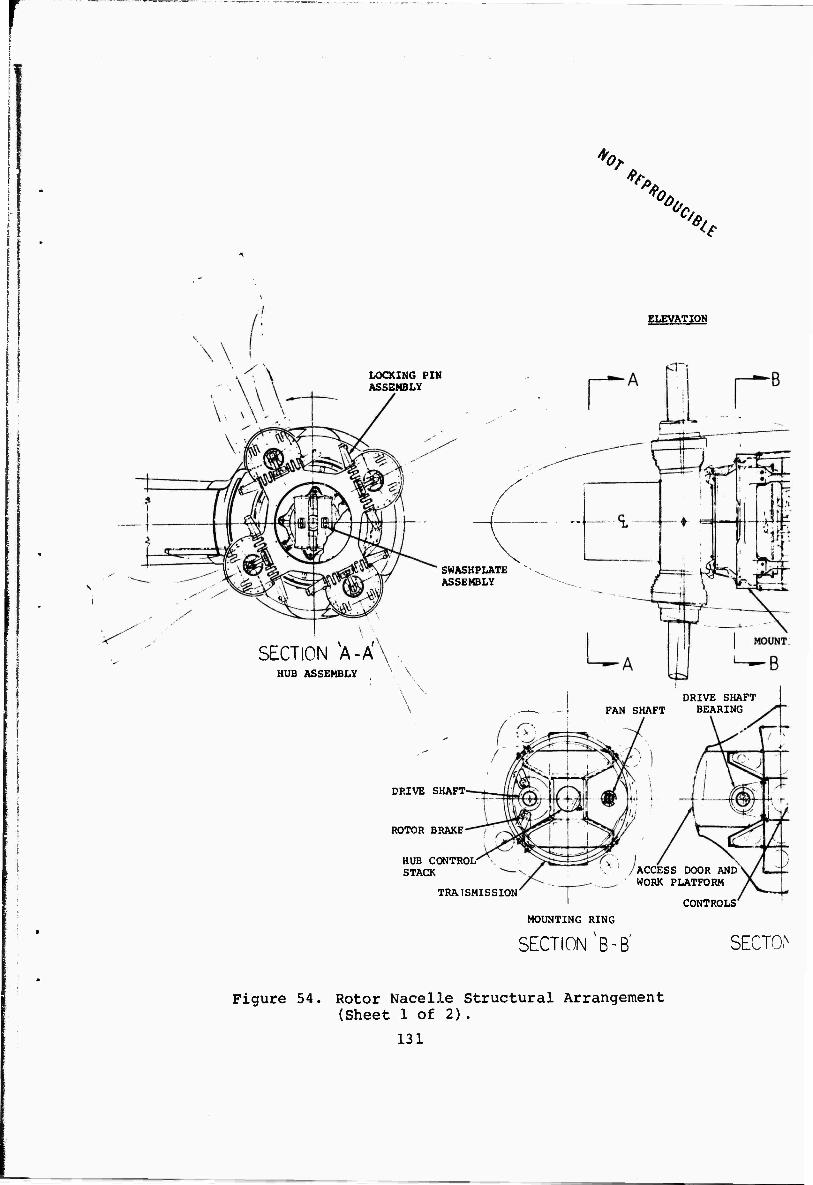
V ̂ K ̂
A v
LOCKING PIN ASSEMBLY
X SWASHPLATE ASSEMBLY
SECTION XA-A'\ HUB ASSEMBLY
ELEVATION
DRIVE SHAFT FAN SHAFT BEARING
DRIVE SHAFT-
ROTOR BRAKE
HUB CONTROL- STACK
TRA1SMISSION
ACCESS DOOR AND WORK PLATFORM
CONTROLS
MOUNTING RING
SECTION ^B-B' SECTOh
Figure 54. Rotor Nacelle Structural Arrangement (Sheet 1 of 2).
131
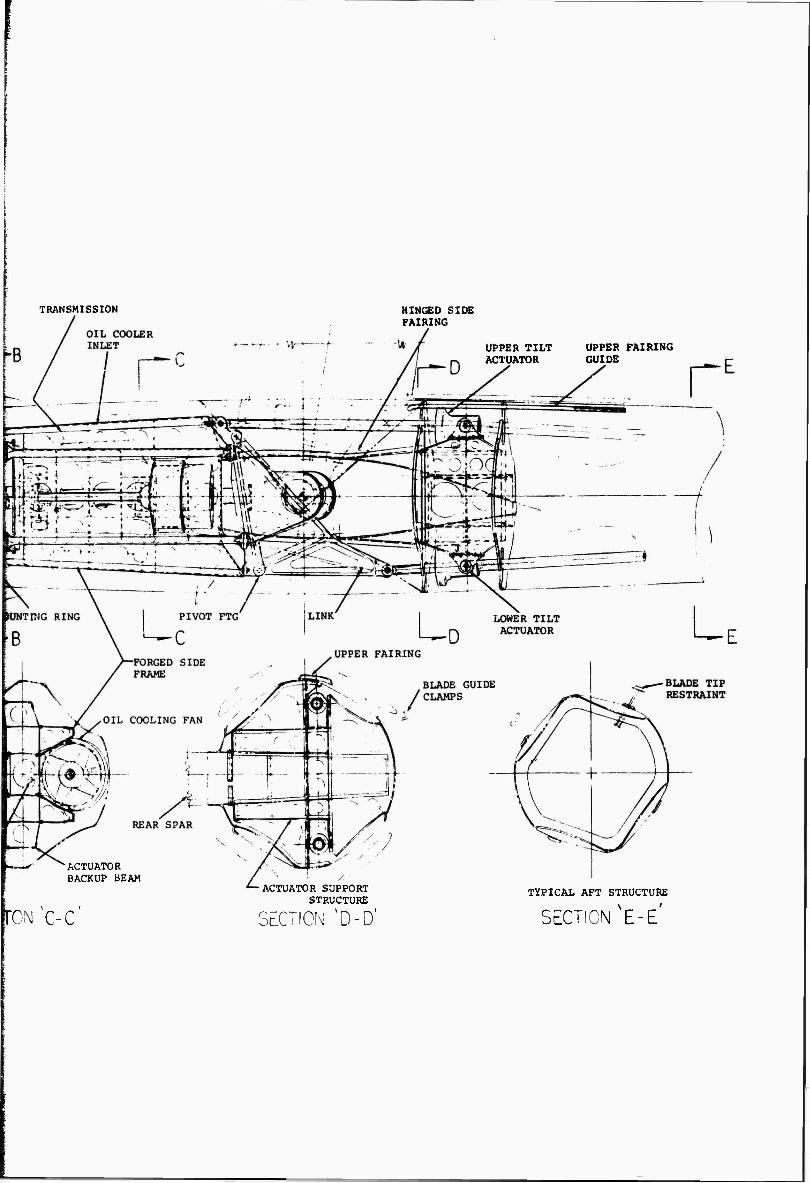
TRANSMISSION HINGED SIDE FAIRING
UPPER TILT UPPER FAIRING ACTUATOR GUIDE
"ACTUATOR BACKUP BEAM
)N C-C
ACTUATOR SUPPORT STRUCTURE
SECTION 'D-D'
TYPICAL AFT STRUCTURE
SECTION NE-E'
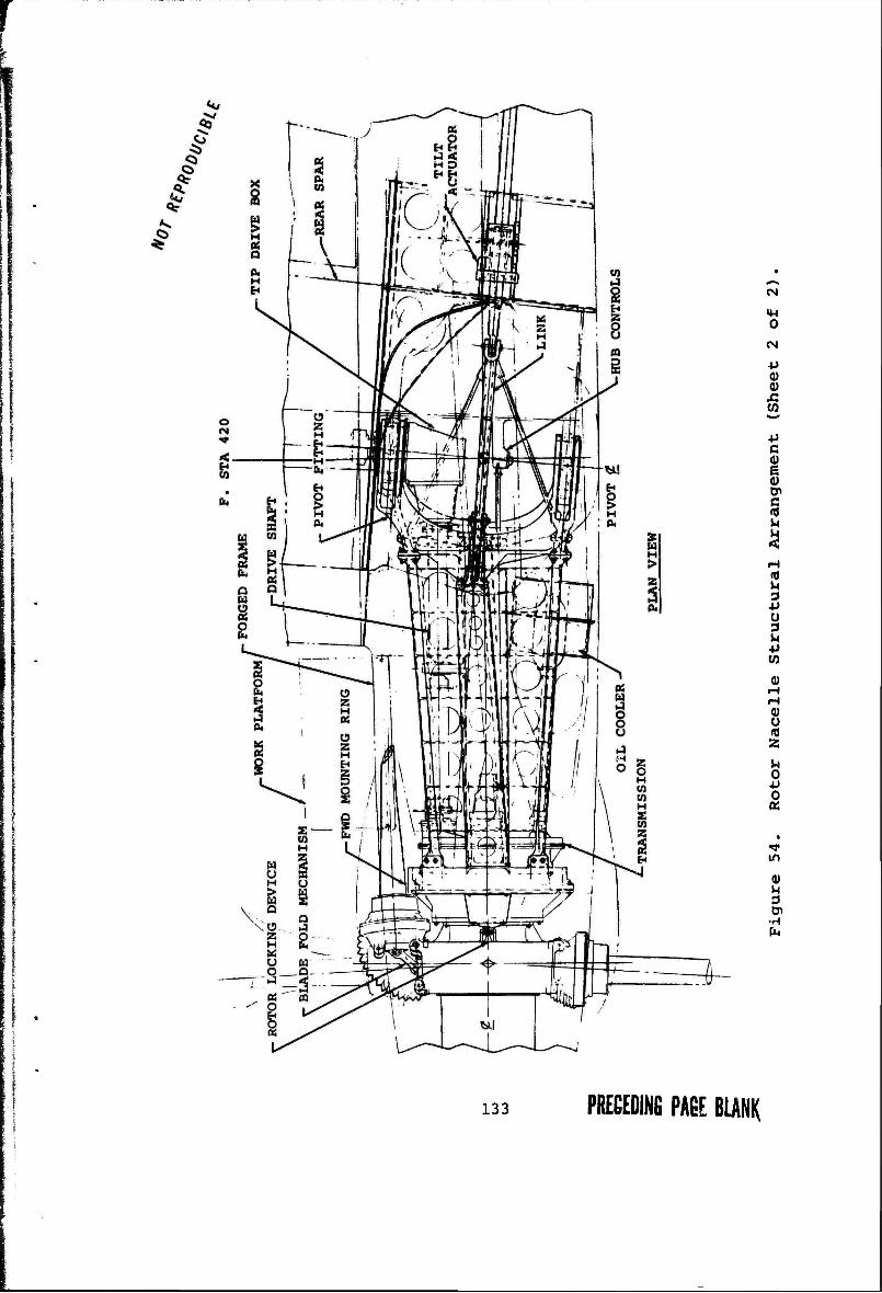
(N
CM
0) 0)
w
4J c i
0)
8 IT) Z
4J
in
2 .1 fa
133 PRECEDING PABE BLANK
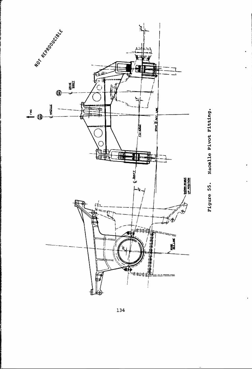
/
/
— (0)—«- •H ■P +> •H fa
I •H
0)
z
in in
•H CM
134
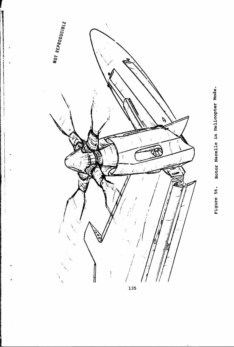
*« £
11
o
ß •H
OJ H H
g s n o +» s
in
Cn ■H
135
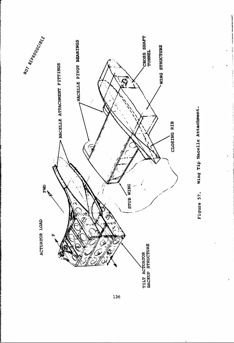
/
#
4i a
+> < 0) H H 0) 0
•H
ß
in
I •rH
136
blades to ox from the cruise configuratior while the aircraft is parked on the ground. Tnis capability depends on the final location of the tilt axis with respect to ground line, wing trailing edge, and rotor overhang propor- tions, as well as the possible provision of a "sideways leaning" landing gear capability.
3. CONCLUSIONS AND RECOMMENDATIONS
This study verifies the original assumption that folding rotors attached to tip-mounted tilting nacelles are feasi- ble. The drawings show the feasibility of providing logical load paths for the reaction of all anticipated aerodynamic, gyroscopic, and inertia loads.
The complete definition of the design criteria and design loads for the nacelle and tilt mechanism is dependent upon the following:
a. Desired aircraft handling qualities.
b. Method chosen to obtain pitch and yaw control during the hover and transition flight modes.
c. Desired maneuver and gust requirements during all flight modes.
d. Desired taxi and ground handling requirements.
Preliminary estimates of some of the loads imposed on the nacelles have been made based on established maneuver requirements and currently acceptable helicopter and air- plane pitch, yaw, and roll rates. Much remains to be learned about the nacelle and actuator loads developed during transition and conversion. Additional work is also needed in the areas of pitch and yaw control and their effects on the aircraft structure. For example, there are three ways in which yawing moments could be generated dur- ing hover and transitional flight. The nacelles could be assumed to be rigid with all forces generated by deflection of the blade tip path plane; the nacelles could be assumed to be free to pivot, with cyclic used only to position the nacelles at the desired angle while the actuators are used only to transmit the trim force required to account for the aircraft eg position; or, a combination of both actuator force and cyclic could be used simultaneously. Obviously, the method chosen will have a considerable effect on the tilt bearing and actuator load distribution.
It is anticipated that furtl^er study and performance of proposed wind tunnel tests will provide enough additional data to permit the selection of the best method of control,
137
with respect to both aircraft response and structural loads. Testing is also expected to provide better data for the determination of loads imposed on the nacelle during blade folding at various forward speeds.
Order of magnitude estimates of the loads imposed due to hover control produce ultimate actuator loads of the order of 110,000 pounds (100 percent yaw plus 50 percent pitch plus trim in helicopter mode) and ultimate pivot bearing loads of the order of 105,000 pounds {2.5g vertical maneuver plus maximum rotor torque in helicopter mode). With the data now in hand, these two conditions appear to be criti- cal tor the nacelle and tilt actuators. Detailed stress analysis and final sizing of the various nacelle components will be possible when more analytical data is obtained on the transition and conversion processes.
The stiffness of the nacelle structure and the relative stiffness through the joint eure expected to have an appreciable effect on the interaction between the rotor induced forces and the behavior of the wing. It is recommended that the dynamic test model be designed to permit variation of the nacelle and joint stiffness so that these relationships may be investigated for a given rotor-wing combination.
Design efforts should be continued, particularly in the areas of the actuators and pivot structure, as additional loading data is generated as a result of the Phase II wind tunnel testing.
138
11
SECTION IX
CONCLUSIONS ANDRECOM4ENDATIONS
In general, the studies show that no major conceptual prob- lems exist for any of the components or systems. All of the required systems and components appear to be mechanic- ally and structurally feasible, and in most instances indicate that further design efforts will permit additional weight savings to be realized.
The weight empty estimates, based on all available data at the conclusion of Phase I; are within 1.5 percent of the initial weight estimates.
1. WING
a. The wing is designed primarily by loads incurred during the helicopter and transition flight modes.
b. A wing designed to withstand the critical ultimate loads possesses adequate stiffness properties to withstand the dynamic loads imposed by the tip-mounted rotors for the flight ranges considered in this study.
c. The unit wing weight is 9 psf using present day technology. It is projected that this can be reduced to 7.7 psf using advanced technology appropriate to a 1976 IOC date. The unit weight of a conventional aircraft wing for an aircraft in this general category would be of the order 5 psf.
d. The outboard portion of the wing is generally torque critical and the inboard portion is generally bending critical.
e. Adequate fuel storage volume is available in the wing for all but ferry missions.
2. NACELLE
a. A four-bladed rotor, for a 67,000 pound gross weight vehicle, can be folded and stowed around a nacelle of 55 inches maximum diameter.
139
b. The nacelle diameter required for blade folding and stowage is compatible with the housing requirements dictated by the transmissions, transmission cooling system, and nacelle tilt system.
c. A nacelle structure providing adequate structural load paths and incorporating adequate cooling is obtainable in a tilting, tip-mounted nacelle.
3. TILT MECHANISM
a. It is possible to design a tilt mechanism which is completely contained within the nacelle.
b. It is possible to isolate the actuator loads from the wing box inside the nacelle so that only the hinge bearing loads are reacted by the aft wing box extending into the nacelle.
c. Final design and sizing of the tilt mechanism is depen- dent upon the hover and transition handling quality requir ^nts and the method chosen to achieve pitch and yaw control. Rotor blade design also influences the loads to be imposed on the tilt mechanism.
d. Transition and conversion wind tunnel testing and analysis are required to firmly establish the complete range of design loads.
4. ROTOR BLADE
a. The use of a combination of nacelle tilt plus cyclic to obtain pitch and yaw forces shows promise of reducing the blade cyclic stresses which would be produced if control is obtained by cyclic only.
b. The use of a blade with a low stiffness root flexure region is indicated in order to obtain acceptable dynamic and stress characteristics.
c. Adequate blade torsional stiffness to provide the desired stall flutter margin can be obtained with the inclusion of boron cross-ply laminates in the root flexure region.
d. An adequate hingeless rotor, meeting the desired stress level, control power, and frequency characteristics, appears to be feasible within the established weight goal.
140
5. ROTOR HÜB AND POLDING MECHANISM
a. Thsre are no hub space constraints on the installation of a workable folding mechanism.
b. A workable folding mechanism concept is presented in the report.
c. The nose mount and blade retention bearing sizes are compatible with the stowage of the blades around a minimum diameter nacelle.
d. Additional design studies of the blade fold mechanism relative stiffness are required to insure compatibility with the structural dynamic requirements during conversion.
6. DRIVE SYSTEM
a. There are no space constraints imposed on the installa- tion of properly sized gearboxes, shafts, or couplings in the present configuration.
b. There are no new or unusual drive system design problems which are peculiar to the stowed-tilt-rotor concept.
Based on the aircraft and component characteristics determined in the Phase I Design Studies, the test program detailed in the Test Plan for Phase II, Document D-213-10001-1, is recommended.
I 141 I
REFERENCES
1. Chalk, Charles et al, PROPOSED MILITARY SPECIFICATIONS FOR V/STOL FLYING QUALITIES, Vol. I-A, Cornell Aeronautical Laboratories, Inc., Buffalo, N.Y.
2. STANDARD METHODS AND ALLOWABLES USED IN THE DESIGN OF VERTOL TRANSMISSION SYSTEM, Document SMR 238, The Boeing Company, Vertol Division, Phila., Pa., August 1965.
3. Willis, J.R., Jr., LIGHTWEIGHT GEARS, NEW EQUATIONS AND CHARTS FOR SELECTION, General Electric Company, Product Engineering, 21 January 1963.
143 FRECEDINß PAGE BLANK