Embed Size (px)
Citation preview

International Journal of Advances in Engineering & Technology, Nov 2011.
©IJAET ISSN: 2231-1963
204 Vol. 1, Issue 5, pp. 204-217
DESIGN AND CONTROL OF VOLTAGE REGULATORS FOR
WIND DRIVEN SELF EXCITED INDUCTION GENERATOR
Swati Devabhaktuni1
and S. V. Jayaram Kumar2
1Assoc. Prof., Gokarajurangaraju Institute of Engg. and Tech., Hyderabad, India
2Professor, J.N.T. University Hyderabad, India
ABSTRACT
This paper deals with the performance analysis of static compensator (STATCOM) based voltage regulator for
self excited induction generators (SEIGs) supplying balanced/unbalanced and linear/non linear loads. A three-
phase insulated gate bipolar transistor (IGBT) based current controlled voltage source inverter (CC-VSI)
known as STATCOM is used for harmonic elimination. It also provides the required reactive power SEIG needs
to maintain a constant terminal voltage under varying loads. A set of voltage regulators are designed and their
performance is simulated using SIMULINK to demonstrate their capabilities as a voltage regulator, a harmonic
eliminator, a load balancer and a neutral current compensator. It also discusses the merits and demerits, to
select a suitable topology of the voltage regulator according to self excited induction generator. The simulated
results show that by using a STATCOM based voltage regulator the SEIG terminal voltage can be maintained
constant and free from harmonics under linear/non linear and balanced/unbalanced loads
KEYWORDS: Self-excited induction generator, static compensator, voltage regulation, load balancing.
I. INTRODUCTION
The rapid depletion and the increased cost of conventional fuels have given a thrust to the research on
self excited induction generator as alternative power sources driven by various prime movers based on
nonconventional energy sources[5]. These energy conversion systems are based on constant speed
prime movers, constant power prime movers and variable power prime movers[6][15]. In constant
speed prime movers (biogas, biomass, biodiesel etc) based generating systems; the speed of the
turbine is almost constant therefore the frequency of the generated voltage remains constant. An
externally driven induction machine operates as a self-excited induction generator (SEIG), with its
excitation requirements being met by a capacitor bank connected across its terminals. The SEIG has
advantages [1][12][16][25] like simplicity, being maintenance free, absence of DC, being brushless,
etc. as compared to a conventional synchronous generator[8][11][13]. A major disadvantage of an
SEIG is its poor voltage regulation [14][24][18]. It requires a variable capacitance bank to maintain
constant terminal voltage under varying loads.
Attempts have been made to maintain constant terminal voltage using fixed capacitor and thyristor
controlled reactors (TCR), saturable-core reactors and short-shunt connections [6][9][19][21]. The
voltage regulation provided by these schemes is discrete but these inject harmonics into the generating
system. However, with the invention of solid state commutating devices, it is possible to make a
static, noiseless voltage regulator which is able to regulate continuously variable reactive power to
keep the terminal voltage of an SEIG constant under varying loads. This system, called STATCOM,
has specific benefits compared to conventional SVC’s[2][23][17].
Basic topology of STATCOM consists of a 3-phase current controlled voltage source converter (VSC)
and an electrolytic capacitor at its DC bus. The DC bus capacitor is used to self support a DC bus of
STATCOM and takes very small active power from SEIG for its internal losses to provide sufficient
reactive power as per requirements [3][10]. Here STATCOM is a source of leading or lagging current
and can be designed in such a way to maintain constant voltage across the SEIG terminals with

International Journal of Advances in Engineering & Technology, Nov 2011.
©IJAET ISSN: 2231-1963
varying loads. In this paper various STATCOM based VR topologies are presented which are based
on two leg VSC, three leg VSC for three phase three wire SEIG system[4][7][20].
An SEIG is an isolated system, which is small in size, and the injected harmonics pollute the
generated voltage. The STATCOM eliminates the harmonics, provides load balancing and supplies
the required reactive power to the load and the generator. In this paper, the authors present a simple
mathematical model for the transient analysis of the SEIG-STATCOM system under
balanced/unbalanced. Simulated results show that the SEIG-STATCOM system behaves as an ideal
generating system under these conditions.
The brief description about this paper includes, Section2 discusses mainly about the various
STATCOM controllers used in this paper with the diagrams. Section 3 includes the design of various
STATCOM techniques included in this paper with the controlling strategies. Section 4 discusses the
results obtained from the MATLAB/SIMULINK models for various STATCOM techniques applied
to a self excited induction generator connected to a grid.Section 5 gives the conclusions of this paper.
The system we tested has the following components:
• a wind turbine
• a three-phase, 3-hp,slip ring induction generator driven by the wind turbine
• various sets of capacitors at stator terminals to provide reactive power to the induction
generator
• a three-phase various STATCOM devices
• a three phase balanced/unbalanced grid
II. SYSTEM STATCOM CONTROLLERS
The VRs are classified as three phase three wire VRs and three phase four wire VRs. These VRs are
based on the two leg VSC, three leg VSC, four leg VSC, three single phase VSC, three leg with
midpoint capacitor based VSC and transformer based VRs. In the following section, detailed system
description is presented for different STATCOM based voltage regulators.
2.1. Three Phase 3-wire voltage regulators Mainly two types of VR topologies are discussed for three phase 3-wire self excited induction
generator (SEIG). The first one is based on three leg voltage source converter (VSC) and another one
is based on a two leg VSC with midpoint capacitor.
2.1.1. Two Leg Voltage Source Converter (VSC) Based Voltage Regulator Figure 1 shows an isolated generating system which consists of a constant speed wind turbine, and
self excited induction generator along with two leg VSC based VR Two legs of VSC are connected to
each phase of the generator through interfacing inductors while the third phase of the generating
system is connected to the midpoint of the capacitors. Midpoint capacitors require equal voltage
distribution across both the capacitors and voltage rating at the DC link of the VSC is comparatively
higher than the 3-leg VSC based topology. However switch counts are reduced in this topology of VR
Fig1: Two leg VSC based VR for SEIG system feeding three phase three wire loads.
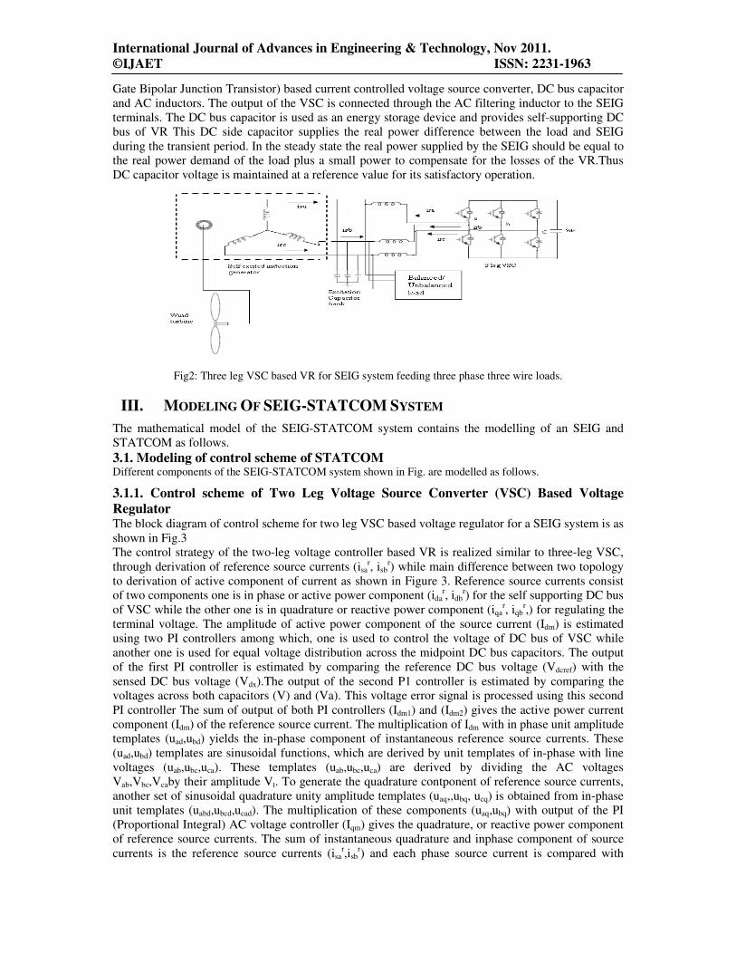
2.1.2 Three Leg Voltage Source Converter (VSC) Based Voltage Regulator Figure 2 shows an asynchronous generator system based isolated generating system along with three
leg VSC based STATCOM based voltage regulator. The VR consists of a three-leg IGBT (Insulated
International Journal of Advances in Engineering & Technology, Nov 2011.
©IJAET ISSN: 2231-1963
Gate Bipolar Junction Transistor) based current controlled voltage source converter, DC bus capacitor
and AC inductors. The output of the VSC is connected through the AC filtering inductor to the SEIG
terminals. The DC bus capacitor is used as an energy storage device and provides self-supporting DC
bus of VR This DC side capacitor supplies the real power difference between the load and SEIG
during the transient period. In the steady state the real power supplied by the SEIG should be equal to
the real power demand of the load plus a small power to compensate for the losses of the VR.Thus
DC capacitor voltage is maintained at a reference value for its satisfactory operation.
Fig2: Three leg VSC based VR for SEIG system feeding three phase three wire loads.
III. MODELING OF SEIG-STATCOM SYSTEM
The mathematical model of the SEIG-STATCOM system contains the modelling of an SEIG and
STATCOM as follows.
3.1. Modeling of control scheme of STATCOM Different components of the SEIG-STATCOM system shown in Fig. are modelled as follows.
3.1.1. Control scheme of Two Leg Voltage Source Converter (VSC) Based Voltage
Regulator The block diagram of control scheme for two leg VSC based voltage regulator for a SEIG system is as
shown in Fig.3
The control strategy of the two-leg voltage controller based VR is realized similar to three-leg VSC,
through derivation of reference source currents (isar, isb
r) while main difference between two topology
to derivation of active component of current as shown in Figure 3. Reference source currents consist
of two components one is in phase or active power component (idar, idb
r) for the self supporting DC bus
of VSC while the other one is in quadrature or reactive power component (iqar, iqb
r,) for regulating the
terminal voltage. The amplitude of active power component of the source current (Idm) is estimated
using two PI controllers among which, one is used to control the voltage of DC bus of VSC while
another one is used for equal voltage distribution across the midpoint DC bus capacitors. The output
of the first PI controller is estimated by comparing the reference DC bus voltage (Vdcref) with the
sensed DC bus voltage (Vdx).The output of the second P1 controller is estimated by comparing the
voltages across both capacitors (V) and (Va). This voltage error signal is processed using this second
PI controller The sum of output of both PI controllers (Idm1) and (Idm2) gives the active power current
component (Idm) of the reference source current. The multiplication of Idm with in phase unit amplitude
templates (uad,ubd) yields the in-phase component of instantaneous reference source currents. These
(uad,ubd) templates are sinusoidal functions, which are derived by unit templates of in-phase with line
voltages (uab,ubc,uca). These templates (uab,ubc,uca) are derived by dividing the AC voltages
Vab,Vbc,Vcaby their amplitude Vt. To generate the quadrature contponent of reference source currents,
another set of sinusoidal quadrature unity amplitude templates (uaq,,ubq, ucq) is obtained from in-phase
unit templates (uabd,ubcd,ucad). The multiplication of these components (uaq,ubq) with output of the PI
(Proportional Integral) AC voltage controller (Iqm) gives the quadrature, or reactive power component
of reference source currents. The sum of instantaneous quadrature and inphase component of source
currents is the reference source currents (isar,isb
r) and each phase source current is compared with

International Journal of Advances in Engineering & Technology, Nov 2011.
©IJAET ISSN: 2231-1963
thecorresponding reference source current to generate the PWM switching signal for VSC of the
controller.
Vt= (1)
Fig.3. Block diagram of control scheme for Two leg VSC based voltage regulator for a SEIG system
3.1.1.1. Design of Two Leg Voltage Source Converter (VSC) Based Voltage Regulator This section presents the detailed design of two-leg VSC based VRs for a SEIG driven by a constant
speed wind turbine. The two leg VSC and its voltage waveforms are shown in Figure 4.
Fig.4.Two leg VSC
The design procedure is focused on, to determine the value of interfacing inductors, DC link
capacitors and the voltage across the DC link capacitors along with the rating of the devices. The
design of the inductor and capacitor depends upon the voltage and current ripples.
3.1.1.2. Design of the Interfacing Inductor
In PWM switching of the converter, VcontrolA,VcontrolB and Vcontrolc can be assumed to be constant to be
constant during one switching frequency time period.At the zero crossing of VcontrolA therefore,
VcontrolA=0
VcontrolB=maVtrisin(120)= ma√ (2)
International Journal of Advances in Engineering & Technology, Nov 2011.
©IJAET ISSN: 2231-1963
208 Vol. 1, Issue 5, pp. 204-217
VcontrolC=maVtrisin(240)=- ma√
When ma is the modulation index and the converter AC terminal voltage vector is defined from the
line to neutral voltages Van,Vbn,Vcnwhich can be calculated as follows:
Van = VaN-VNn=VaN-(VaN+VbN+VcN)
Vbn = VbN – VNn=VbN-(VaN+VbN+VcN) (3)
Vcn = VcN – VNn=VcN-(VaN+VbN+VcN)
Where VaN,VbN and VcN are the converter pole voltages against the midpoint of the DC capacitor and
VNn is the voltage between the neutral point(n) and the midpoint of the DC capacitor(N,C).
Peak to peak inductor current ripple is
ILripple = dt =
(4)
The interfacing inductor Lan,Lbn and Lcn can be calculated as follows:
Lan=Lbn= ! "#$%&#'())*+, -m √ 10 (5)
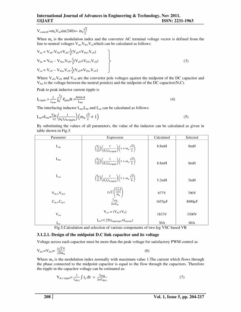
By substituting the values of all parameters, the value of the inductor can be calculated as given in
table shown in Fig.5.
Parameter Expression Calculated Selected
Lan
Lbn
Lcn
Vdc1,Vdc2
Cdc1,Cdc2
Vsw
Isw
!V212, 4 15 f7i&99:; 41 < √32 ;
!V212, 4 15 f7i&99:; 41 < √32 ;
!V26 , 4 15 f7i&99:; 41 < √34 ;
2√2 @- √0m A
BCD2E2
Vsw = (Vdc+Vd)
Isw=1.25(iripple(pp)+Is(peak))
8.8mH
8.8mH
5.2mH
677V
1655µF
1833V
30A
8mH
8mH
5mH
700V
4000µF
3300V
60A
Fig.5.Calculation and selection of various components of two leg VSC based VR
3.1.2.1. Design of the midpoint D.C link capacitor and its voltage
Voltage across each capacitor must be more than the peak voltage for satisfactory PWM control as
Vdc1=Vdc2= √ √F (6)
Where ma is the modulation index normally with maximum value 1.The current which flows through
the phase connected to the midpoint capacitor is equal to the flow through the capacitors. Therefore
the ripple in the capacitor voltage can be estimated as:
Vdc1-ripple= G H iI dt =
LMNωG H (7)

International Journal of Advances in Engineering & Technology, Nov 2011.
©IJAET ISSN: 2231-1963
Iavg ≈ 0.9 Is (8)
Where Iavg is the average current which flows through the DC bus capacitor (Cdc1) and Isis the required
rms compensator current rating of the devices. The voltage rating (Vsw) of the device can be
calculated under dynamic condition as:
Vsw = (Vdc+Vd) (9)
Where Vd is 10% overshoot in the DC link voltage under dynamic conditions.
Rated current which flows through the two leg VSC is Is.The peak value of the current flows through
the VR considering the safety factor of 1.25 the maximum device current can be calculated as:
Isw = 1.25(iripple(pp)+Is(peak)) (10)
From this voltage(Vsw) and current rating(Isw) of the IGBT switches can be estimated.Here one design
example for a two-leg VSC based VR is carried out for feeding 0.8p.f lagging reactive load,SEIG
requires reactive power of 140-160% of rated generated power.Therefore the additional reactive
power required from no load to full load at 0.8 lagging p.f load and it is calculated as:
Additional VAR(QAR)=√3VIs (11)
Where V is SEIG line voltage and Isis VR line current.
3.1.2. Control scheme of Three Leg Voltage Source Converter (VSC) Based Voltage
Regulator The block diagram of control scheme for two leg VSC based voltage regulator for a SEIG system is as
shown in Fig.6.
Fig.6. Block diagram of control scheme for three leg VSC based voltage regulator for a SEIG system
3.1.2.1. Modelling of control scheme of STATCOM
Different components of the SEIG-STATCOM system shown in Fig.6 are modelled as follows.
From the three-phase voltages at the SEIG terminals (Va,Vb and Vc), their amplitude (Vt) is computed
as:
Vt= (12)
The unit vector in phase with Va,Vb and Vc are derived as:
ua= O;ub=
PO ; uc= PO (13)

International Journal of Advances in Engineering & Technology, Nov 2011.
©IJAET ISSN: 2231-1963
210 Vol. 1, Issue 5, pp. 204-217
The unit vectors in quadrature with Va,Vb and Vcmay be derived using a quadrature transformation of
the in-phase unit vectors ua,ub and uc as:
wa =QRP√ +
R √
wb =√ u RPQR √ (14)
wc = - √ u RPQR √
3.1.2.2. Quadrature component of reference source currents The AC voltage error Ver(n) at the n
th sampling instant is:
Ver(n) = Vtref(n) – Vt(n) (15)
Where Vtref(n) is the amplitude of the reference AC terminal voltage and Vt(n) is the amplitude of the
sensed three-phase AC voltage at the SEIG terminals at the nth
instant. The output of the PI controller
(I*smq(n)) is used for maintaining constant AC terminal voltage at the nth sampling instant.
The qudrature components of the reference source currents are computed as:
i*saq = I*
smqwa ; i*sbq = I*
smqwb ; i*
scq = I*smqwc (16)
3.1.2.3.In-phase component of reference source currents
The error in the DC bus voltage of the STATCOM (Vdcer(n)) at the nth sampling instant is:
Vdcr(n) = Vdcref(n) – Vdc(n) (17)
whereVdcref(n) is the reference DC voltage and Vdc(n) is the sensed DC link voltage of the STATCOM.
The output of the PI controller is used for maintaining the DC bus voltage of the STATCOM at the nth
sampling instant.
The in-phase components of the reference source currents are computed as:
i*sad = I*
smdua
i*
sbd = I*smdub (18)
i*sad = I*
smduc
3.1.2.4. Total reference source currents
The total reference source currents are the sum of the in phase and quadrature components of the
reference source currents as :.
i*
sa = i*
saq + i*sad
i*
sb = i*sbq + i
*sbd (19)
i*sc = i*
scq + i*scd
3.1.2.5. PWM current controller
The total reference currents (i*sa, i
*sb and i
*sc) are compared with the sensed source currents (isa, isb and
isc).The ON/OFF switching patterns of the gate drive signals to the IGBTs are generated from the
PWM current controller. The current errors are computed as:
isaerr = i*
sa - isa
isberr = i*sb - isb (20)
iscerr = i*sc - isc

International Journal of Advances in Engineering & Technology, Nov 2011.
©IJAET ISSN: 2231-1963
211 Vol. 1, Issue 5, pp. 204-217
These current error signals are amplified and then compared with the triangular carrier wave. If the
amplified current error signal is greater than the triangular wave signal switch S4 (lower device) is ON
and switch S1 (upper device) is OFF, and the value of the switching function SA is set to 0. If the
amplified current error signal corresponding to isaerr is less than the triangular wave signal, switch S1 is
ON and switch S4 is OFF, and the value of SA is set to 1. Similar logic applies to the other phases.
3.1.2.6.Modeling of STATCOM
The STATCOM is a current controlled VSI and is modeled as follows:
The derivative of its DC bus voltage is defined as:
pVdc = & TU& PTVU& TGG (21)
Where SA, SB and SC are the switching functions for the ON/OFF positions of the VSI bridge
switches S1-S6.The DC bus voltage reflects the output of the inverter in the form of the three-phase
PWM AC line voltage eab, ebcand eca. These voltages may be expressed as:
eab = Vdc(SA-SB)
ebc = Vdc(SB-SC) (22)
eca = Vdc(SC-SA)
The volt-amp equations for the output of the voltage source inverter (STATCOM) are:
Va = Rfica + Lf pica + eab –Rficb -Lfpicb
Vb = Rficb + Lfpicb + ebc –Rficc -Lfpicc (23)
ica + icb + icc =0 (24)
The value of icc from above eqn (24) is substituted into eqn.(23) which results in:
Vb = Rficb + Lfpicb + ebc +Rfica+Lfpica +Rficb +Lfpicb (25)
Rearranging the equation results in:
Lfpica – Lfpicb = Va –eab-Rfica+Rficb (26)
Lfpica +2Lfpicb = Vb –ebc-Rfica-2Rficb (27)
Hence, the STATCOM current derivatives are obtainedby solving eqns. and as:
pica = WPQP UQPQXY& ZY (28)
picb = WPQP QQPQXY& PZY (29)
3.1.2.7. AC Line Voltage at the Point of CommonCoupling
Direct and quadrature axis currents of the SEIG (ids and iqs) are converted into three-phases (a, b and
c). The derivative of the AC terminal voltage of the SEIG is defined as:
pVa = W&Q&'Q& Q&PQ&'PQ& PZG
(30)
pVb = W[Q[\]Q[]U[^Q[\^Q[]^Z_

International Journal of Advances in Engineering & Technology, Nov 2011.
©IJAET ISSN: 2231-1963
Va+Vb+Vc = 0 (31)
Where ia ,ib and ic are the SEIG stator line currents, ira,irb and ircare the three phase load line currents
and ica,icb and icc are the STATCOM currents. C is the per phase excitation capacitor, which is
connected across the SEIG terminals.
IV. RESULTS AND DISCUSSIONS
The SEIG-STATCOM system feeding linear/non-linear and balanced/unbalanced loads are simulated
and results are shown in Figs.7-8 . For this study, a 3.5 kW, 440V,7.5A, 4-pole machine was used as a
generator and the parameters of the generator are given in the Appendix.
4.1. Performance of two Leg voltage Regulator for a SEIG System
Here performance of two leg voltage source converter with mid point capacitor based VR topology
has been simulated using MATLAB/SIMULINK and verified for self excited induction generator
driven by wind turbine.
Generated voltage Line current
Rotor speed Electromagnetic Torque
D.C voltage
Terminal Voltage
Load voltage and load current
Fig.7.Performance of two leg VSC based VR for a SEIG system feeding 3-phase balanced/unbalanced grid
International Journal of Advances in Engineering & Technology, Nov 2011.
©IJAET ISSN: 2231-1963
213 Vol. 1, Issue 5, pp. 204-217
Figure 7 shows the transient waveforms of three-phase generator voltages (vabc), generator currents
(iabc), speed, electromagnetic torque, D.C voltage, terminal voltage, load voltage and load current
respectively demonstrating the response regulating the SEIG terminal voltage while supplying a grid.
At 0.3seconds, three-phase nonlinear load is applied and it is found that with application of the sudden
load, there is increased generator currents, load currents, STATCOM currents and decrease in supply
voltage due to supplying active and reactive power to the load.The voltage is 75volts and current is
10A.
Along with this, short circuit occurs at 0.4seconds,with this there is further increased generator
currents, load currents, STATCOM currents and decrease in supply voltage due to supplying active
and reactive power to the load.The voltage is 20volts and current is 15A.
At 0.5seconds the STATCOM is connected to the system. Due to this the voltage is reached to the
required voltage. It is observed that the generator voltage remains constant underbalanced and even
unbalanced lagging pf loads. Variations in generator speed are observed with the change in load due
to the drooping characteristic of the wind turbine.
The STATCOM is disconnected from the system at 0.55seconds after it reaches the required voltage.
At 0.6 seconds short circuit is removed and at 0.7 seconds is removed from the load. Now the
machine is working under steady state conditions.
The total harmonic distortion (THD) of the generator voltage and current for the three-phase balanced
case are observed.It is observed that the THD is less than 5%.
With the application of the three phase nonlinear loads and short circuits it is found that Voltage
regulator responds in a desirable manner and maintains constant voltage at the generator terminal.
Along with this, the DC link voltage and voltage across both midpoint capacitors of voltage regulators
also remain equal and constant.
The STATCOM eliminates harmonics so that the generator voltages and currents are free from
harmonics a scan be observed
4.2. Performance of three Leg voltage Regulator for a SEIG System
Here performance of three leg voltage source converter with a capacitor based VR topology has been
simulated and verified for self excited induction generator driven by wind turbine.
Figure 8 shows the transient waveforms of three-phase generator voltages (vabc), generator currents
(iabc), speed, electromagnetic torque, D.C voltage, terminal voltage, load voltage and load current
respectively demonstrating the response regulating the SEIG terminal voltage while supplying a grid.
At 0.3seconds, three-phase nonlinear load is applied and it is found that with application of the sudden
load, there is increased generator currents, load currents, STATCOM currents and decrease in supply
voltage due to supplying active and reactive power to the load.The voltage is 75volts and current is
10A.
Along with this, short circuit occurs at 0.4seconds, with this there is further increased generator
currents, load currents, STATCOM currents and decrease in supply voltage due to supplying active
and reactive power to the load.The voltage is 20volts and current is 15A.
At 0.5seconds the STATCOM is connected to the system. Due to this the voltage is reached to the
required voltage. It is observed that the generator voltage remains constant underbalanced and even
unbalanced lagging pf loads. Variationsin generator speed are observed with the change in loaddue to
the drooping characteristic of the wind turbine.
The D.C voltage obtained here is having fewer ripples compared with the two leg voltage regulator
for a SEIG system. Due to these transients there is even change in the variation of the speed and the
torque.

International Journal of Advances in Engineering & Technology, Nov 2011.
©IJAET ISSN: 2231-1963
Generated voltage Line current
Rotor speed Electromagnetic torque
D.C voltage Terminal voltage
Load voltage and load current
Fig.8.Performance of three leg VSC based VR for a SEIG system feeding 3-phase balanced/unbalanced grid
V. CONCLUSIONS
A set of VRs have been designed and their performance have been studied for SEIG system. For
three-phase three-wire SEIG system two topologies of VR have been demonstrated one is based on
three leg VSC while another one is based on the two leg VSC. A topology which is based on the two
leg VSC, requires higher voltage rating of the switches and equal voltage distributed DC link,
however less number of switching devices are required compared to three leg VSC based topology of
VR. In three phase three wire SEIG system there are a number of configurations of the VRs for a
three phase four wire SEIG system . It is observed that the developed dynamic model of the three-
phase SEIG–STATCOM is capable of simulating its performance while feeding linear/non-linear,
International Journal of Advances in Engineering & Technology, Nov 2011.
©IJAET ISSN: 2231-1963
215 Vol. 1, Issue 5, pp. 204-217
balanced /unbalanced loads under transient conditions. From these results, it is found that the SEIG
terminal voltage remains constant and sinusoidal under a three-phase or a single phase rectifier load.
When a single-phase rectifier load is connected, the STATCOM balances these unbalanced load
currents so that the generator currents and voltages remain sinusoidal, balanced and constant and,
thus, STATCOM acts as a load balancer. A rectifier based non-linear load generates harmonics, which
are also eliminated by STATCOM. Therefore, it is concluded that the STATCOM acts as a voltage
regulator, a load balancer and a harmonic eliminator. Although different aspects of uncontrolled
rectifiers have been modelled as non-linear loads here, the developed model can easily be modified to
simulate a compensating controlled rectifier as a nonlinear load. For future work they may develop
the various STATCOM techniques by considering the neutral line and can develop the 3-leg and 4-leg
wire systems.
REFERENCES
[1] M. H. Salama and P. G. Holmes, “Transient and steadystate load performance of a stand-alone self-excited
induction generator,” IEE Proc. Electr. Power Appl. Vol.143, No. 1, pp. 50-58, January 1996. [2] L. Wang and R. Y. Deng, "Transient performance of an isolated induction generator under unbalanced
excitation capacitors," IEEE Trans. on Energy Conversion, Vol. 14, No. 4, pp. 887-893, Dec. 1999.
[3] S. K. Jain, J. D. Sharma and S. P. Singh, “Transient performance of three-phase self-excited induction generator
during balanced and unbalanced faults,” IEE Proc. Gener. Transm. Distrib., Vol. 149, No. 1, pp. 50-57,January
2002.
[4] M. B. Brennen and A. Abbondati, "Static exciter for induction generator," IEEE Trans. on Industry applications,
Vol. 13, No. 5, pp. 422-428, 1977. [5] L ShridliaxBhim Singh, and C.S. Jha, “‘Transient performance of the self regulated short shunt self excited
induction generator,” IEEE ‘trans. on Energy Conversion, vol. 10, no. 2, pp. 261-267, June 1995.
[6] K. Muijadi, and TA Lipo, “Series compensated PWM inverter with battery supply applied to an isolated
induction generator,” IEEE hans. on Industry Applications, vol. 30, no.4, pp. 1073-1082.
[7] J.K Chatterjee, PK& Khan, A. Anand, and A..Jinclal, “Performance evaluation of an electronic leadlagVAr
compensator and its application in brushless generation,” m Proc. Inter Conf. on Power Electronics and Drive
Systems, vol.1, May 1997, pp. 59-64.
[8] Bhim Singh, and LB. Shilpalcar, ‘Analysis of a novel solid state voltage regulator for a selfexcited induction
generator,” TEE Proc Caner Transm. Distrib.,voL 145, no.6, pp. 647-655, November 1998.
[9] E.C. Marra, and J.A. Pomilio, “Self excited induction generator controlled by a VSPWM converter providing
high power factor current to a singlephase grid,” in Proc. Annual Conference of the IEEE on Industrial
Electronics Societ)ç 1998, pp. 703- 708.
[10] B. Singh, L Shridhar, and C.S. Tha, “Improvements in the performance of selfexcited induction generator
through series compensation,” TEE Proc.CenerTransm. andDistnl,, voL 146, no 6, pp. 602-608, November
1999.
[11] R. Leidhold, and C. Garcia, “Parallel capacitive and electronics excited stand alone induction generator,” in
Proc. International Conf. on Electric Machines and Drives, 1999, pp. 631- 633.
[12] 0. Ojo, and I.E. Davidson, “PWMVSI inverter assisted standalone dual stator winding induction generator,” in
Proc. Thirty Fourth lAS Annual Meeting on Industry Applications, 1999, pp. 1573 -1580.
[13] EC. Marra, and J.A. Pomllio, “Induction generator based system providing regulated voltage with constant
frequency” in Proc. Conf. Applied Power Electronics, 1999, pp. 410-415.
[14] PICS. Khan, J.K Chatteijee, MA Salam, and if Ahmad, “Transient performance of unregulated prime mover
driven standalone selfexcited induction generator with solidstateleadlagVArcompensatoz,” in Proc. TENCON
2000, voL 1, Sep. 2000, pp. 235- 239.
[15] Bhim Singh, S.S. Murthy, and Sushma Cupta, ‘Analysis and design of STATCOM based regulator for self
excited induction generator,” IEEE Trans. on Energy Conversion, vol. 19, na 4, pp. 783-790, Dec. 2004.
[16] Bhim Singh, S.S. Murthy, and Sushma Cupta, “STATCOM based voltage regulator for self excited induction
generator feeding nonlinear loads,” IEEE Trans. on Industrial Electronics, vol. 53, pp 1437-1452, Oct. 2006.
[17] WoeiLnen Chen, YungHsiang Lin, HrongShengCau, and ChiaHung Yu, “STATCOM controls for a selfexcited
induction generator feeding random load.s,” IEEE Transactions on Power Delweq accepted for future
publication.
[18] ppKhera, “Application of zigzag transformers for reducing harmonics in the neutral conductor of low voltage
distribution system,” in Proc. IEEE LAS Conf. Rec., 1992, Pp. 1092—1990.
[19] PN. Enjeti, WajihaShireen, Paul Packebush, and Ira J. Pitel, Analysis and design of a new active power filter to
cancel neutral current harmonics in three phase four Wire electric distribution systems” IEEE Transactions on
Industry Applications, vol. 30, no.6, pp. 1565-1572, Dec. 1994.
[20] M. Lzhar, G.M. Hadzeç M. Syahdn, S. Tails, and S. Tdns ‘An analysis and design of a star delta transformer in
series with active power filter for current hamonics reduction,” in Proc. National Power and Energy Conference
(PECon) 2004, Kuala Lumpur, Malaysia, pp. 94-98.
[21] Sewan Choi, and Minsoo Jang, “A ReducedRating Hybrid Filter to Suppress Neutral Current Harmonics in
ThreePhaseFourWire Systems,” IEEE Trans. on Ind. Electron., vol. 51, no.4, pp. 927-930, Aug. 2004.

International Journal of Advances in Engineering & Technology, Nov 2011.
©IJAET ISSN: 2231-1963
[22] HumgLiehng Jon JinnChang Wi KuenDer Nu, WenJung Chiang, and YiHsun Chen, ‘Analysis of zigzag
transformer applying in the threephasefourwire distribution power system” IEEE Transactions on Power
Delivery, vol. 20, no. 2, pp. 1168-1173, Jan. 2005.
[23] Sewan Choi, and Minsoo Jang, “Analysis and control of a singlephaseinverter— zigzagtransformer hybrid
neutralcurrent suppressor in threephasefourwire systems,” IEEE Transactions on Industrial Electronics, vol. 54,
no.4, pp. 2201-2208, Aug. 2007.
[24] H.R Karshonas, and A Abdolahi, ‘Analysis of a voltage regulator for selfexcited induction generator employing
currenttype static compensator,” in Proc. Canadian Conf. on Electrical and Computer Engineering, vol. 2, May
2001, pp.1053 -1058.
[25] S.C. Kuo, and L Wang, “Analysis of voltage control for a selfexcited induction generator using a
currentcontrofled voltage source inverter (CCVSI),” TEE Proc.CenerTransrmtDistrib., vol. 148, no. 5, pp. 431-
438, Sept. 2001.
APPENDIX
1. STATCOM Control Parameters
Lf = 1.2 mH, Rf = 0.045 Ω and Cdc= 4000µF.
AC voltage PI controller: Kpa =0.05, Kia = 0.04.
DC bus voltage PI controller Kpd = 0.7, Kid =0.1
Carrier frequency = 20 kHz
2. Parameters of Rectifier Load
Three-phase rectifier LsL=0.1mH, RSL = 1 Ω, RRL = 22Ω, and CRL = 470µF.
Single-phase rectifier LSL=0.1mH, RSL = 1 Ω, RRL=75Ω and CRL=150Μf
3. Machine Parameters
The parameters of the 3.5 kW,440V, 7.5A, 50 Hz,4-pole induction machine are given below.
Rs = 0.69 Ω, Rr= 0.74Ω, Lls = Llr = 1.1 mH, J = 0.23kg/m2,
Lss = Lls + Lm and Lrr = Llr + Lm.
4. Terminal capacitor
C = 15 µF/ phase
5. Air gap voltage:
The piecewise linearization of magnetization characteristic of machine is given by:
E1=0 Xm≥260
E1=1632.58-6.2Xm 233.2≤Xm ≤260
E1=1314.98-4.8Xm 214.6≤Xm ≤233.2
E1=1183.11-4.22Xm 206≤Xm ≤214.6
E1=1120.4-3.9.2Xm 203.5≤Xm ≤206
E1=557.65-1.144Xm 197.3≤Xm ≤203.5
E1=320.56-0.578Xm Xm≤197.3
Author
Swati Devabhaktuni received the B.Tech degree in electrical and electronics engineering
from V. R. Siddhartha Engineering College, Andhra University, India in 2001, and the
M.Tech degree in control systems from J.N.T.U University, in 2004. Currently, she is a
Associate professor in Gokarajurangaraju Institute of engineering and technology,
Hyderabad, She is also a Research Scholar in J.N.T.U University, Hyderabad. Her research
interests are the power electronics, AC motor drives, and control systems.
S. V. Jayaram Kumar received the M.E. degree in electrical engineering from the Andhra
University, Vishakapatnam, India, in 1979. He received the Ph.D. degree in electrical
engineering from the Indian Institute of Technology, Kanpur, in 2000. Currently, he is a
professor at Jawaharlal Nehru Technological University, Hyderabad. His research interests
include FACTS and Power System Dynamics,A.C drives.