Embed Size (px)
Citation preview
D-A127 994 STRTE-OF-THE-RRT ASSESSMENT OF TESTING AND TESTABILITY i/iOF CUSTOM LSI.'VLSI..(U) AEROSPACE CORP EL SEGUNDO CAENGINEERING GROUP M A BREUER ET AL. OCT 82
UNCLASSIFIED TR-8983(3982-64)-i-VOL-± SD-TR 83-29-VOL-i F/G 9/5 N
DIIIo 1.02.0
MICROCOPY RESOLUTION TEST CHARTNATIONAL BUREAU OF STANDARDS.1963-A
AM:,
REPORT SDTR-83-20
State-of-the-Art Assessment ofTesting and Testability of
*, Custom LSI / VLSI Circuits
Volume 1: Executive Summary
M. A. BREUER & ASSOCIATES*Encino, Calif. 91436
and
A. J. CARLANTechnical Study Director
October 1982
Enginerifg Group-: THE AEROSPACE CORPORATION
El Segundo, Calif. 90245
Prepared for
SPACE DIVISION-. - AIR FORCE SYSTEMS COMMAND
Los Angeles Air Force StationP.O. Box 92960, Worldway Postal Center
Los Anseles, Calif. 90009
.CD
APPROVED FOR PUBLIC RELEASE; k'DISTRIBUTION UNLIMITEDE
iEEiss 0r 0,.
This final report was submitted by the Aerospace Corporation, El Segundo,
CA 90245 under Contract No. F04701-82-C-0083 with the Space Division, Deputy
for Logistics and Acquisitions, P.O. Box 92960, Worldway Postal Center, Los
Angeles, CA 90009. It was reviewed and approved for The Aerospace Corporation
by J. R. Coge, Electronics and Optics Division, Engineering Group. Al Carlan
was the project engineer.
This report has been reviewed by the Office of Information and is releas-
able to the National Technical Information Service (NTIS). At NTIS, it will
be available to the general public, including foreign nationals.
This technical report has been reviewed and is approved for publication.
Publication of this report does not constitute Air Force approval of the
report's findings or conclusions. It is published only for the exchange and
stimulation of ideas.
FOR THE COMMANDER
APPROVED
I
STEPHEN A. HUNTER, LT COL, USAFDirector, Speciality Engineering
and Test
4-
UnclassifiedSECURITY CLASSIFICATION OF T14IS PAGE (tei Dage Ente.. __________________
Vol. I Execuive SumaryEFOREN OG.LETORG FUOR
SD-TR-83 _ _ _ __ _ __ _ _ __ _ _ __ _ _ __ _ _ R 08200 -0 -4. TITLE(n util)) TYEO REPTOR GT ERODCERED
M.ateor-uer Assaesmn of0Testng8andInteri
~~~~~~~~~~~~S. PERFORMING OROIAINNM N DRES1 RGA LMN. REP~OET. TASKE
M.A. Breuer & Associates AREA a ORK UNI NUMUER
16857F Bosqsde Dr.Encino, CA 91436
)I. CONTROLLING OFFICE NAME AND ADDRESS It. REPORT DATE
Space Division October 1982Air Force Systems Coimmand Is NUMDER OF PAGESLos Angeles, Calif. 90009 23
14. MONITORING AGENCY NAMM A ADDRESS(If diffeent 1mm Corfnd Office) IS. SECURITY CLASS. (of this rop..t)
The Aerospace Corporation Unclassified* . l Sguno, alif 9045 ~a.DECLASSI FICATION/ DOWNGRAING
SCHEDULE
14. DISTRISUTION STATEMENT (of this Re~or)
Approved for public release; distribution unlimited
17. DISTRIUUTION STATEMENT (of the abstract entered in Block 20. II 1irt barn Report)
III. SUPPLEMENTARY NOTES
19. KEY WORDS (Contenue on reverse side It necesary and identify by' block numbor)
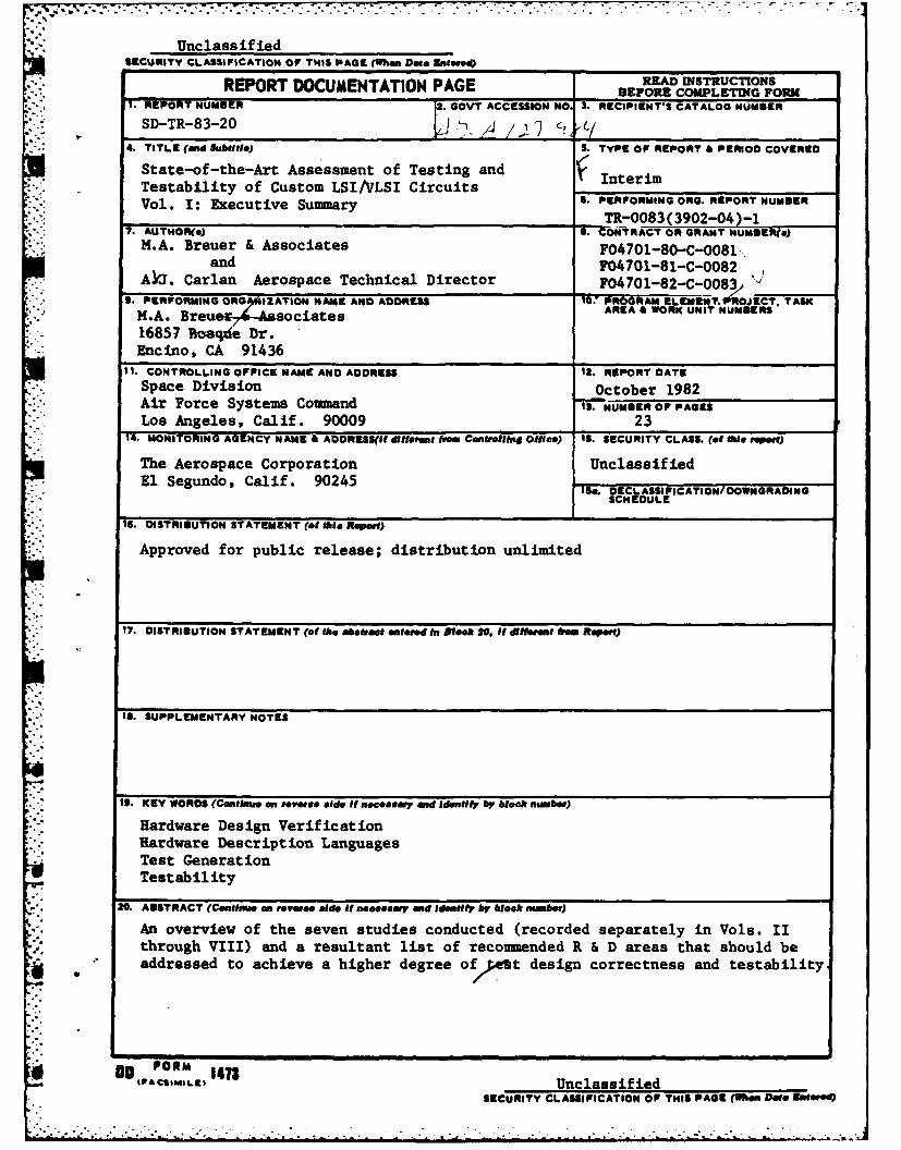
Hardware Design VerificationHardware Description LanguagesTest GenerationTestability
20. ASTRACT (Cmntinai an reves side It necessary and Idmntify by WeekS nubor)
An overview of the seven studies conducted (recorded separately in Vols. IIthrough VIII) and a resultant list of recounended R & D areas that should beu addressed to achieve a higher degree of/et design correctness and testability.
Do FORM1473tPACSMILEUnclassified
SECURITY CLASSIFICATION OF THIS PAGE (When. Data EntereSD)
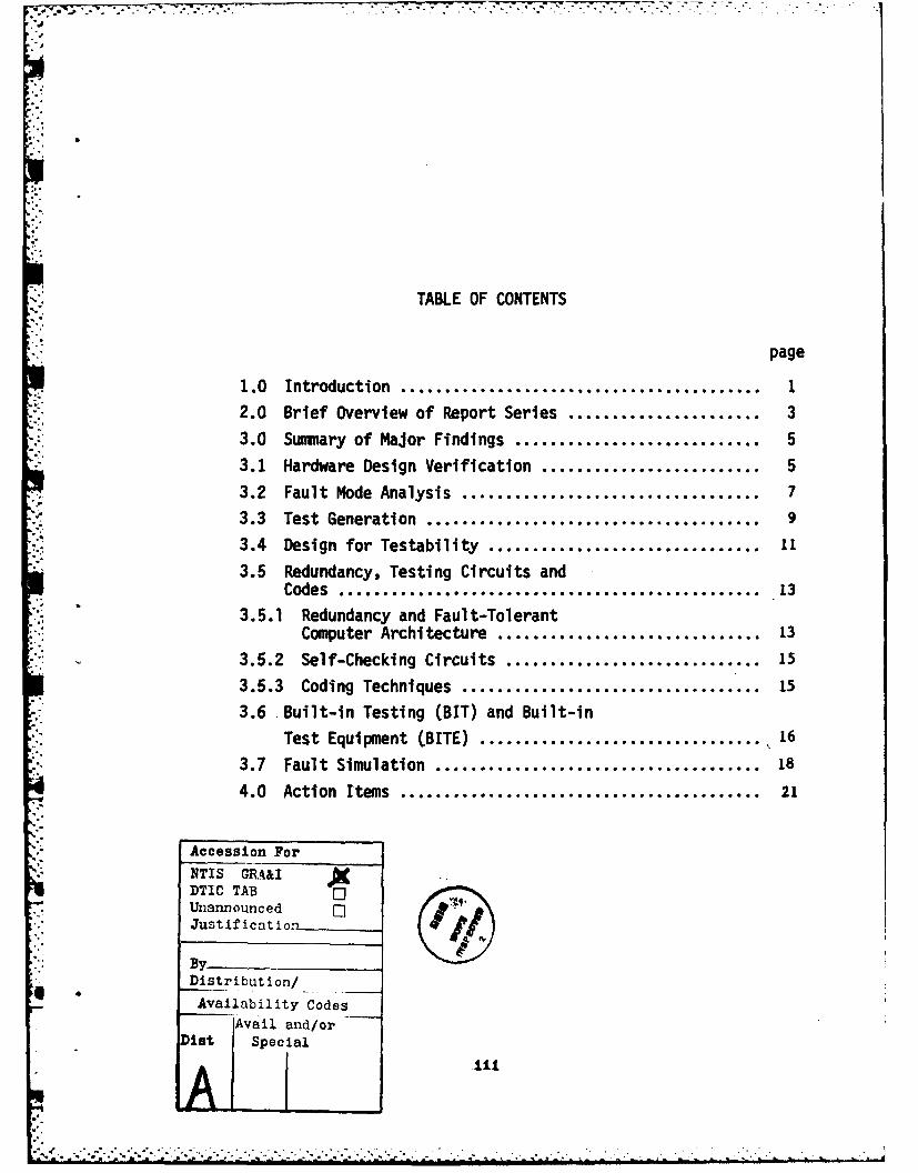
TABLE OF CONTENTS
page
1.0 Introduction ......................................... 1
2.0 Brief Overview of Report Series ................... 3
3.0 Summary of Major Findings ............................ 5
3.1 Hardware Design Verification ...................... 5
3.2 Fault Mode Analysis .................................. 7
. 3.3 Test Generation ...................................... 9
3.4 Design for Testability ............................... 11
3.5 Redundancy, Testing Circuits andCodes ............................................... 13
3.5.1 Redundancy and Fault-TolerantComputer Architecture .............................. 13
3.5.2 Self-Checking Circuits ............................. 15
3.5.3 Coding Techniques .................................. 15
3.6 Built-in Testing (BIT) and Built-in
Test Equipment (BITE) ............................ 16
3.7 Fault Simulation .................................... 18
4.0 Action Items ........................................ 21
Accession For
NTIS GRA&IDTIC TABUnannouncedJustification
By"* Distribution/
Availability CodesAvail and/or
Dist Special
A'I. "

1.0 INTRODUCTION TO REPORT SERIES
This project is being funded (incrementally) as a two-phase
* study dealing with testing and testability of custom LSI/VLSI
circuits. The tasks summarized and evaluated in this report
consisted of compiling and documenting a survey and assessment of
the state-of-the-art for each of seven topics. Each of these
topics has resulted in a formal report and are listed below:
-4-r Vol II: Hardware Design Verification;March 1981 (Task 1)
2. Vol. III: Fault Mode Analysis,July 1981 (Task 2)
.- I
3. Vol. Ir: Test GenerationFebruary 1981 (Task 3)
4. Vol.-V: Design for Testability,-July 1981 (Task 4)
5. Vol.-Vr: Redundancy, Testing Circuits, and Codes,December 1981 (Task 5)
6. '- Vol-V-H: Built-in Testing (BIT) and Built-in Test
Equipment (BITE)' o-,.-August 1981 (Task 6)
7. Vol, -V-It: Fault Simulation,August 1981 (Task 7)
This report consists of, in part, the cumulative executive
* summaries of these seven reports.
In Section 2 we give a brief overview of the subject of each
report. In Section 3 we present our findings for each of the
seven subjects under consideration. Finally, in the last section
we present several R&D action items which should be pursued if
the goals of high quality design verification and testing are to
be achieved.
-I
3
2.0 BRIEF OVERVIEW OF REPORT SERIES
Prior to testing a system one may as the questions (1) were
the design specifications correct, i.e., does this system really
do what was intended, and (2) are there any logical errors in the
design? The answer to these questions deals with problems of de-
sign specification, validation and verification. If there are
errors in any of these areas, there is little point to carrying
out hardware test generation. The'issues of design specification
and realization are addressed in Vol II: Hardware Design
Verification.
Prior to testing for hardware failures one must first iden-
tify the predominant modes of failure and how such failures are
manifested. These subjects are dealt with in Vol III: Fault
Mode Analysis.
Once fault modes and models for these fault modes have been
identified, methods for constructing tests to detect these faults
can be invented. Numerous such techniques are described and
evaluated in Vol IV: Test Generation. Here the goal is to de-
sign algorithms such that given a description of a circuit to be
tested, automatic test generation can be carried out.
For modern complex circuits test generation becomes infeasi-
ble unless testability is an important aspect of the design
objective. Vol V: Design for Testability reviews some of the
more successful techniques used in the design of a circuit so as
to make test generation feasible.
In the design of some digital systems hardware redundancy is
often used to either Increase system reliability or to achieve
self-testing. Techniques used to achieve these goals include
duplication, triple modular redundancy (MR), hybrid redundancy,
coding, and self-checking circuits. These concepts are reported
in Vol VI: Redundancy, Testing Circuits, and Codes.
* Rather than testing a circuit by applying externally gener-
ated stimuli and measuring chip output responses, it is often
desirable to have the chip test-itself by employing built-in
-J
4
tests. The hardware required to support this form of testing is
called built-in test hardware. These subjects are covered in Vol
VII: Built-in Testing (BIT) and Built-in Test Equipment (BITE).
Finally, given a proposed test for a circuit, it is often
necessary and useful to "grade" the test, i.e., to determine the
fault coverage of this test. This can be achieved by using a
fault simulator, which is the subject of Vol VIII: Fault
Simul ation.
It is believed that the results of this study can be used in
serveral ways. First, these results can be used as the kernel
for creating a military standard for specifying the design, veri-
fication and testing of custom large scale and very large scale
integrated circuits for use in spacecraft, launch vehicles, and
other high reliability applications.
Secondly, the techniques presented and evaluated can be used
by design engineers to achieve the specified standards.
Finally, the areas denoted as being less than adequately
handled clearly indicate where further research and development
is required.
-•
a°.-.
-.
3.0 SUMMARY OF MAJOR FINDINGS
3.1 HARDWARE DESIGN VERIFICATION
Digital designs have become complex. Specification of de-
sign requirements and determination that a design meets these
requirements is no longer a casual matter. Correctness of
digital designs is the subject of Vol II: Hardware Design
Verification.
Two major issues have been investigated
0 How to specify design requirements for digital systemsto designers/contractors.
0 How a designer/contractor can verify or validate that adesign meets the above requirements.
Both of these issues have been researched with increasing acti-
vity over the past five years. Some results are available and
have been applied by industry on a small scale to successfully
validate and verify a few designs.
The specification of design requirements is done with nar-
*rative description diagrams, or formal hardware descriptive lan-
. guages. The most complete technique uses hardware descriptive
* languages (HDLs) to describe hardware function. An HDL descrip-
tion or program bears strong resemblence, in many cases, to a
software program written to execute the same function on a com-
puter. The main difference between HOLs is the level of detail
which can be included. Some HDLs describe interconnected gates;
others describe black-box behavior of sequential machines. The
more detail which is specified, the more likely a design is to
meet requirements. However, supplying large amounts of detail
is, in essence, doing the design itselft. Thus, there is a
balance between supplying too little information, allowing for
the possibility of ambiguity and hence design or. specification
errors, and supplying most of the design itself (which itself may
be in error).
°° a
.* . p. * - . . - * * ** * -* -. . .C
The state-of-the-art in HOLs has advanced to the point that
they are widely used by industry, but primarily for simulation.
They are used increasingly for design documentation. The use of
such language for design specification to contractors is
practical at this time, with some limitations and exceptions.
'.X
'...
".4-
N,-:
Verifying that a design meets some specified requirements is a less
mature discipline.. There are three approaches to this task
v Simulation
v Symbolic simulation
v Formal proofs
ranked in decreasing order of usage. Simulation is widely used. However,
sim zation only provee correotnese for the apecific cases 8iraulated. Sym-
bolic simulation, on the other hand, uses symbols as input data tothe sim-
ulator. The outputs from the simulator are functions of these input sym-
bols. In theory, all possible cases can be examined in this manner. Amer-
ican and Japanese companies have reported results in this area, although
the extent of practical application of this technique is as yet not known.
Formal proofs, much like geometric proofs, for example, have been
used in academic studies to prove correctness. This is the most rigorous
type of analysis but is not likely to be employed by industry in the near
future since it is tedious and only small problems have at present been
successfully processed.
In short, formal languages (HDLs) can be used to specify design re-
quirements. Some validation, via simulation, is possible at this time.
Symbolic simulation is a technique which shows promise.
It appears that what is achievable today is the use of human inter-
vention in automatic verification techniques. Verification, much like de-
sign, should be directed by humans with the creative decisions under man-
ual control, but with the painstaking details and bookkeeping under con-
trol of a machine.
Of all the areas studied in this project, the areas of formal design
specification and verification were the least mature and appear to re-
quire the most research and development effort.
3.2 FAULT MODE ANALYSIS
A larg, number o specific physical fault modes have been recognizedto occur in .,..'ta systems due to manufacturing defects and various wear-
out mechanisms. These failures are usually highly dependent on the fab-
..........
..........

8
rication technology being used, and may result in very complex faulty
behavior. To reduce the numbers and types of faults that must be han-
dled during test generation and fault simulation to manageable levels,
various logical fault modes have been proposed, in which failures are
.- characterized by their effects on the logical structure and behavior of
the system under consideration. The use of logical rather than physi-
cal fault models simplifies fault analysis, and makes it relatively in-
dependent of circuit technology. However, not all fault modes that occur
in practice can be easily or accurately modeled in this manner. For ex-
ample, some lines and components appearing in a physical circuit have no
counterparts in the corresponding logic circuit and vice versa.
Logical fault modes can be classified in terms of their time-vari-
ance, the number of primitive faults present simultaneously, and the
fault's effect on component behavior, interconnection structure, and op-
erating speed. By far the most widely used fault model is the single
stuck line or SSL model. An SSL fault allows any single signal line in
a circuit to be permanently stuck at the logic value 0 or 1; component
behavior and operating speed are unaffected. The popularity of the SSL
model has several reasons. Many common physical faults are equivalent
to SSL faults. The line-by-line analysis characteristic of test genera-
tion techniques like the 0-algorithm makes SSL faults very easy to handle.
.. Finally, practical experience indicates that test sets derived for SSL
faults thoroughly exercise a circuit, thereby detecting many faults that
cannot be modeled directly as SSL faults. However, except in simple cases,
it is very difficult to identify the non-SSL faults covered by a given
test set for SSL faults. Thus to guarantee 100 percent fault coverage, it
is generally necessary to consider other fault modes in addition to SSL
faults.
*IP If several signal lines cre allowed to be stuck simultaneously, then
-the multiple stuck line or MSL fault model is obtained. MSL faults are
*: difficult to deal with directly, because their number grows exponentially
-. *with the number of lines present. In practice, a complete set of SSL
-* tests can be expected to cover all MSL faults. An MSL fault can escape

'
9
detection only if certain complex masking conditions are present. Short-
circuit faults are more difficult to deal with. Their number is also
large and, unlike stuck-line faults, they can introduce unwanted feed-
back. The occurrence of short-circuit and other non-standard fault modes
can be minimized by careful circuit layout.
Non-standard faults like short circuits are usually modeled by modi-
fying the original circuit so that an SSL fault can be introduced that is
equivalent to the target fault in the unmodified circuit. Although such
"workarounds" are costly to construct, they allow standard SSL-based test
software to be applied to most non-standard faults. This approach can be
used, for example, to handle CMOS faults that introduce "parasitic" mem-
ory elements. Another fault mode found in MOS VLSI circuits is pattern
sensitivity caused by unwanted signal interactions. Promising fault
models for pattern sensitive faults in random-access memories have been
devised, but they have not been incorporated into test generation soft-
ware. Heuristic testing methods, whose underlying fault modes are not
explicitly defined, continue to be very widely used for complex faults.
It is important to continue the study of fault modes as new techno-
logies and manufacturing processes emerge. In addition, the relationship
between physical fault modes and fault models must continue to evolve.Finally, it should be noted that modifying the layout of a circuit has a
.* significant impact on the fault modes and hence the applicable models.
3.3 TEST GENERATION
Test generation methods for digital systems may be divided into two
major categories: those based on detailed logic-circuit models of the
unit under test (UUT), and those based on high-level functional descrip-
tions of the UUT. Most general-purpose test generation programs in cur-
rent use implement some version of Roth's D-algorithm. These programs
typically require a gate-level circuit description of the UUT and only
yield tests for faults of the single line stuck-at-O/1 type. Many modi-
fications to the D-algorithm have been developed to reduce its computa-
*tion time. While the need for basing test generation methods on higher-
level circuit models has been recognized, only a few limited attempts to
implement such systems have been reported. A variety of different schemes
have been developed for deriving tests from functional models of the UUT,
::,7
10
particularly where the UUT is microprocessor-controlled. Heuristic me-
thods employing self-test programs are widely used in such cases. Re-
cently some promising work has been described that uses exact functional
fault models for test generation in microprocessor-controlled systems. Con-
siderable interest has also been shown in compact testing methods that in-
volve pseudorandom test pattern generation and fault signature analysis.
Finally, various testing procedures have been developed for specialized
fault types found in LSI/VLSI designs, for example, high-density RAM faults
* and delay faults.
*: The problem of generating tests for single stuck-at-O/1 faults in
combinational circuits is considered to be solved. Essentially complete
test sets can be obtained for most combinational circuits, even those con-
taining thousands of gates, using current implementations of the D-algo-rithm. Computational problems have been encountered with some kinds of
code-checking circuits, but special methods to handle these circuits have
been devised. Little attention has been given to test generation for
other fault types, such as multiple stuck-line faults or short circuits.
However, there is evidence that tests generated for the standard single
stuck-line model provide good coverage for these other fault types. The
D-algorithm has been successfully extended to deal with small and medium-
sized synchronous sequential circuits containing up to about a hundred flip-
flops. Poor results are obtained for unstructured sequential circuits,
such as those containing deeply buried flip-flops, due to the exponential
growth of test computation time with the number of memory elements present.
Asynchronous circuits pose even greater difficulties.
The D-algorithm has been successfully applied to sequential circuits
in the LSI/VLSI range only when a highly-structured circuit design method-
ology like IBM's level-sensitive scan design (LSSD) has been followed. Be-
sides being easily testable for the standard stuck-at faults, LSSD designs
have proven particularly amenable to delay fault testing. The main draw-
back of LSSD is the slow rate at which test patterns must be applied; thus
LSSD is not suitable for all applications. To handle large non-LSSD cir-
cuits, it appears necessary to develop computationally efficient test gen-
eration techniques that treat higher-level circuit components such as reg-
isters, multiplexers, ALUs, etc. as primitive. Although some research is
being conducted into this problem, useful test generation programs are not
yet generally available.

Very complex systems, such as those containing microprocessors, are
usually tested in a heuristic fashion. Heuristic test generation me-
thods attempt to test a device by systematically exercising all its ma-
jor functions. While computationally efficient, the fault coverage of
such approaches is uncertain, a consequence of the lack of an explicit
fault model. Some work has been reported on fault models that are suit-
able for microprocessor-based systems. However, not all types of micro-
processors or faults are included in this work. Considerable effort has
, been devoted to test generation for random-access memories, and a lib-
rary of standard test algorithms has been compiled. Again fault cover-
age is unclear, particularly in the case of pattern-sensitive faults.
While the use of compact testing methods such as Hewlett-Packard's sig-
nature analysis approach has been increasing, serious doubts have been
raised about its fault coverage also.
Several aspects of test generation technology are likely to be pur-
sued vigorously in the next five years. Methods of the D-algorithm type
will probably be extended to accommodate more complex primitive elements.
Easily testable design methodologies such as LSSD and built-in compact
testing will see increased use, since they allow known test generation
methods to be used for VLSI systems. However, it also is expected that
emphasis will be placed on the development of new design methods that
leadto systems with better testability characteristics such as short
* testing time and 100% fault coverage. It is probable that there will be
increased interest in test generation methods that can be incorporated
into VLSI chips to make then self-testing, both to overcome IC pin limi-
tations and to simplify field maintenance procedures. Finally it is ex-
pected that attention will be devoted to developing more complete detec-
tion methods for the newer fault types that are found in VLSI systems.
Many of these faults, like stuck-at-open and parasitic flip-flop faults
in CMOS circuits, are not covered at all by traditional fault models.
3.4 DESIGN FOR TESTABILITY
Design for testability is motivated by the need to reduce the costs
associated with testing and maintaining a digital system over its working
life. These costs depend on many interrelated factors which are poorly
..

12
understood and difficult to quantify. Major testability considerations
include test generation difficulty, test sequence length, test applica-
tion cost, fault coverage and fault resolution. Testability can also
be measured indirectly with much less computational effort in terms of
two general circuit properties called controllability and observability.
Several computer programs have been written recently that compute con-
trollability and observability measures for a given circuit. These
programs provide practical tools for comparing the testability of dif-
ferent designs, and can also be used to indicate testing bottlenecks
within circuits. The use of such programs is very limited at present.
Two approaches to design for testability have evolved: ad hoc de-
sign rules to improve the testability of a given logic circuit, and gen-
eral design approaches with testability as the primary design objective.
The use of test and control points which attempt to improve local ob-
servability and controllability, respectively, is one of the most use-
ful of the ad hoc design guidelines. Suitable sites for test points can
readily be determined, and include flip-flop set/reset lines, deeply buried
components, points of high fan-in or fan-out such as major buses, and log-
ically redundant subclrcults. The principal limitation on this technique
is the small number of extra 10 pins or connectors available for testing
purposes. Testability can also be improved by restructuring a circuit,
for example, by opening feedback loops for other strongly connected sub-
circuits during testing. Additional important design rules include the
avoidance of asynchronous timing, and the provision of a mechanism where-
by a tester can override or synchronize with the internal clock of thecircuit under test.
Because testability involves many tradeoffs, very few general design
techniques are known that yield highly testable circuits without sacri-
ficing other important practical considerations. The most promising of
these are the scan-in/scan-out methods represented by IBM's LSSD (Level
Sensitive Scan Design) technique. The basic idea of scan-in/scan-out
is to design a circuit so that its memory elements can be linked together
to form a shift register SR during testing. This allows the circuit's
state (the contents of SR) to be directly controlled and observed by an
.:. ..,............._..... ......... y..-:.:.:......:: ,::.. ... .. ":. .

13
external tester. Since access to *R is serial, only one or two extra
pins are required. Furthermore, most of the circuit is seen as a
(large) combinational circuit, for which test pattern generation is
relatively easy. LSSD-type circuits have the disadvantage of requir-
ing rather long testing times; they are also impractical for circuits
such as RAM chips that contain thousands of memory elements. Another
promising design approach of more limited applicability is bit-slicing.
Bit-sliced systems consist of an array of identical elements called
(bit) slices. The individual slices are relatively easy to test, and
tests for an array can be easily derived from those of a slice.
Over the next five years it is likely that increased attention
will be paid to design for testability because of the rapid increases
in chip complexity resulting from VLSI technology. The use of computer
programs that evaluate the testability of unstructured designs Is likely
to increase. However, structured design like LSSD and bit-slicing lead
to systems that are easy to design and test, and may displace unstruc-
tured designs in many applications. Scan-in/scan-out methods like LSSD,
and related methods like Selective Control, will become more widely used.
They meet some of the major constraints imposed by VLSI technology, and
allow current test generation methods like the D-algorlthm to be used
effectively. Not all circutis are suitable for scan-in/scan-out designs,
particularly circuits with very large numbers of memory elements. Dif-
ferent approaches which will probably employ self-testing will be re-
quired in such cases.
3.5 REDUNDANCY,. TESTING CIRCUITS, AND CODES
3.5.1 Redundancy and Fault-Tolerant Computer Architecture
Redundancy is one important way of achieving fault tolerance, higher
system reliability, and self-testing. The framework of redundancy con-
sists of (I) modeling and evaluation of the redundancy constructs, and
(II) the embodying of the constructs in faults-tolerant computer archi-
tecture.
Mathematical modeling of redundancy constructs permits their quanti-
tative evaluation and provides a numeric basis for critical comparison.

o-.- 1.
14
Case histories of fault-tolerant computer architecture illustrate,
by the design selection of particular redundancy constructs from theA repertoire of constructs, the relative significance that the designer
placed on specific redundancy constructs in relation to their functional
environment In the architecture.
In general, a system of designed in such a manner that only the ab-
solute minimum amounts of hardware is utilized to implement its function
is said to be non-redundant or is said to have a 8nplex structure. If
even after utilizing the finest components available the desired system
capability is not achieved or ij: failure-tolerance is desired as a system
capability then redundancy as a design procedure is resorted too, i.e.,
more system elements are used than were absolutely necessary to realize
all the system's functions (excepting for the attributes of reliability
and fault-tolerance). The additional system elements, referred to as the
redundant elements, need not all necessarily be hardware elements, but may
also be additional software (software redundancy), additional time (time
redundancy) and additional information (information redundancy). Examples
of the latter are the application of error-detection and correction codes.
Naturally, the hardware, software, and time redundancy are often in-
terrelated. Additional software requires additional memory storage and
additional time is used to execute the added software. The term protec-
tive redundancy is often used to characterize that redundancy which has
an overall beneficial effect on the system attributes,since redundancy
alone without proper application may well become a liability. Protective
redundancy is utilized to realize fault-tolerant digital systems and self-
repai ng systems by such means as triple or N-tuple modular redundancy
(TMR, NMR), quadded redundancy, standby-replacement redundancy, hybrid
redundancy, software redundancy and the application of error-detection
and correction codes.
For the computer age, redundancy has been usedatall levels of tech-
nology, from that of VLSI devices, circuitry, logic, subsystems, computers,
and even to entire networks of digital systems.
V.

15
The utilization of the various protective redundant structures as
basic building blocks for fault-tolerant digital computing systems are
well known and can be evaluated comparatively. A unifying notation for
characterizing the most commonly used protective redundancy schemes
exists. The k-out-of-N redundant model subsumes either directly or by
composition a great number of other redundant structures.
By employing reliability analysis to these fault-tolerant systems,
their overall reliability can be measured and compared. Numerous com-
puter aids exist for carrying out these analyses.
3.5.2 Self-checking Circuits
Self-checking circuits by definition pertain to circuits whose out-
puts are encoded in an error-detecting code. The underlying theory based
on code spaces for self-checking circuits, partially self-checking cir-
cuits, totally self-checking circuits, and totally self-checking networks
*: is well known.
There are several problems related to the use of self-checking cir-
cuits. First, these circuits are restricted to be self-checking with
respect to a class of failure modes, such as the single stuck-at faults.
Also techniques for employing these circuits are not well known and un-
derstood. Finally, though these techniques can be generalized to deal
with arbitrary I/0 relations, they are usually always restricted to cir-
cuits whose inputs are encoded. In summary, these circuit structures
have not received the attention that they probably deserve, both in terms
of their use as well as research and development.
3.5.3 Coding Techniques
Coding techniques are used to achieve concurrent diagnosis in digital
computing systems. Coding theory is the body of knowledge dealing with
the science of redundantly encoding data so that errors can be detected,
and with further encoding, even corrected.
r.0:..
' +'/ " ': + '" + ' "" ' "" " -"" "" ' " '" + " ° " m N m,,ll m,,,,nml,.,U.m , d -- .,-,r ' ',,, .,,' . .:m,.-:-.; .,,,,J, ,, I

16
The fundamental principles underlying transmission codes as well
as arithmetic codes are well developed and known. Both error detection
as well as error correction can be achieved and the relative tradeoffs
can be calculated.
Coding theory is a very rich and by far the most developed branch
of fault-tolerant computing. The theoretical basis, the functional lim-
its of reliable communication for a given channel, and the mathematical
tools and classification schemes are well established. These techniques
can be employed in the design of more reliable and testable hardware.
Codes are required for self-checking hardware. Codes are used exten-
sively to detect and/or correct transmission errors on buses, memory
errors, and to a smaller extent, computational errors. Unfortunataly,
there is usually not a strong well known correlation between fault modes
and code errors. Some new work appears to be addressing this problem.
3.6 BUILT-IN TESTING (BIT) AND BUILT-IN TEST
EQUIPMENT (BITE)
Built-in testing (BIT) refers to the use of testing procedures that
form an integral part of a system's design, while built-in test equip-
ment (BITE) denotes the special hardware, firmware or software used to
implement BIT. BIT/BITE is employed principally to increase confidence
in the system's correctness, to reduce system down-time due to faults,
."' and to lower overall maintenance costs. BIT techniques fall into two
major groups: concurrent testing methods which allow testing to occur
during normal system operation, and nonconcurrent testing methods which
require a special test mode during which normal system operation is tem-
porarily halted.
Most concurrent BIT schemes employ error-detecting codes and self-
checking circuits; these are the subject of another report in this ser-
ies. Two other important concurrent approaches are: replication with
comparison, and electrical monitoring. Hardware replication involves
the parallel operation of two or more copies of U, the unit to be tested.
The copies of U operate in step on the same input data, and their output
signals are continuously compared by a disagreement detector. Replica-
°.' ** -.. ,. ''.* * .* .c *. .. . .

. -". . ~
17
tion with comparision has the advantage of providing very complete cov-
erage for all types of faults, including intermittent faults. ErrorsS." are detected with a minimum of delay and, if desired, their effects can
easily be masked resulting in a fault-tolerant system. The main disad-
"" .vantages of this approach are the extra cost, bulk, and power consump-
tion of the replicated units. The electrical monitoring approach uses
built-in circuits that detect current or voltage changes that exceed
specified threshold values. It is primarily useful for detecting short-
circuit and open-circuit faults involving interconnection lines. To
date its use has been limited to current-mode logic circuits, where it
appears to require a very small overhead in extra circuitry or IC area.
It also has the ability to detect partial failures and can thus signal
an impending fault before it actually occurs.
Systems employing nonconcurrent BIT/BITE have two operating modes:
a normal mode during which no testing takes place, and a test mode dur-
ing which normal system operation is suspended. The system must contain
circuits to generate explicit test patterns. While, in principle, any
*technique for external testing can be adapted to BIT, only methods in-
volving a small overhead in BITE are of practical interest. Extensive
use is made of diagnostic software or firmware that resides in a memory
of the system to be tested. Diagnostic (micro-) programs are usually
relatively short, and exercise the major system functions in heuristic
fashion. They are easily implemented in microprocessor-based systems,
but their fault coverage is usually difficult to determine.
A second class of nonconcurrent BIT techniques use hardware-imple-
mented BITE. Very efficient testing can be achieved by precomputing
all test patterns and response data off-line, and then storing them in
a system ROM. This approach is constrained by the size of the test
data, which is usually excessive except for certain cases, such as bit-
-- sliced systems. The use of compact testing methods, like signature
analysis, are actively being investigated as a way of introducing BIT
to VLSI circuits. In a typical implementation, two linear feedback
shift registers are attached to the unit to be tested, one to generate
a pseudo-random sequence of test patterns, the other to compress the
- 18
response sequence into an error-sensitive fault signature. While some
promising results using this approrach have been reported, serious
doubts about the effectiveness of signature analysis have been raised,
which have yet to be resolved.
In general, numerous ad hoc techniques for achieving BIT exist
whose effectiveness has been proven by experience. It is possible to
build a system which is self-testing with respect to a given fault model,
but a high degree of design expertise is needed. Evaluating the effec-
tiveness of a given BIT design is usually quite difficult, and may re-
quire extensive and costly simulation. It is also not known how to in-
corporate BIT/BITE requirements into system specifications in a satis-
factory manner.
3.7 FAULT SIMULATION
Fault simulation is widely used in industry primarily in such ap-
plications as scoring the fault coverage of a test sequence, construc-
tion of fault dictionaries, and as an aid in test pattern generation by
using it to determine the set of faults detected by a candidate test.
There are three basic fault simulation approaches in current use,
known as parallel, deductive and concurrent simulation. Of these, con-
current fault simulation (which is the newest of the three) appears to
be the most accurate in terms of timing, and is very compatible with
functional models, multi-valued logic and adaptability to new fault
modes and new logic primitives. Its major disadvantage is in the very
large amount of memory that it requires.
An important issue in the evaluation of a simulator is its accur-
acy, that is, its modeling capability. Modeling accuracy is determined
by the types of primitives available to the simulator. Gate-level mod-
eling of a network results in high state and timing accuracy but may not
be practical for VLSI. Functional-level modeling is less accurate, but
the modeling effort is reduced and the simulation speed is improved, thus
making it more suitable for simulation of VLSI circuits. Development of
efficient mixed-level simulators which can handle circuit descriptions
at both a low-level and a high-level is a desired objective. On the
. ...
"--' :- ' : - : ' ; ." "- ' ". . ." " -". "' % i I" . .. ... -' " " "
19
issue of logic values, the use of two-valued logic (0,1) is totally in-
adequate. Simulators must employ multi-valued logic in order to repre-
sent unknown signal values, high-impedance, various signal transitions,
*- pulses, etc. Accurate simulation must also take into consideration cir-
* .cuit delays, such as transport, ambiguity, rise/fall and inertial delays.
Modeling of delays in complex functional primitives is particularly dif-
ficult.
Another important feature of a fault simulator is the fault modes
that it is capable of handling. Though most simulators primarily handle
stuck-at faults, this may not be adequate for some VLSI technologies.
Nor is it adequate for high-level modeling.
Most fault simulators in current use handle stuck-at faults and em-
ploy parallel fault simulation at the gate level with three or four logic
values. Most of the new simulators or the ones under development employ
concurrent fault simulation with some functional or mixed-level modeling
capability under development. Additional trends in fault simulation in-
clude the processing of more complex fau lt modes, allowing for dynamic
switching of models, and the development of new techniques to improve sim-
ulation efficiency and accuracy.
.*
21
4.0 ACTION ITEMS
From the results of our analysis, the following R&D areas should
be addressed in order to help achieve a higher degree of design correct-
- . ness and testability.
1. Formal methods should be developed and documented for specifying
digital systems.
2. Formal methods should be developed and documented for verifying
*. the correctness of designs at all levels, such as logical descriptions
and masks. Computer-aided tools should be developed to help achieve these
goals.
3. Tables should be constructed documenting the relationship between
a) Technology
b) Fault modes and their probabilities
c) Fault coverage (probability of not detecting a
bad chip) vs percent fault detection of a class
of fault modes
d) Manufacturing process
e) Fault coverage vs the quality of functional
testing
4. More effective automatic test generation systems, such as TEST/80,
which can handle complex primitives, timing, and functionality need to be
developed.
5. Numerous design for testability techniques exist. These should
*- be documented in encyclopedic form for easy reference for design engineers.
Items should be documented as to their effect on such items as test gener-
ation, reliability, yield, hardware overhead and effectiveness.
6. New research is required in the area of checking circuits in or-
der to extend their applicability to larger classes of codes and fault
modes. Also, the various known self-checking circuits should be categor-
ized and their existence and properties made available to design engineers.
I;:'
22
8. While powerful automatic test generation and fault simulation
systems exist in some companies, their availability is not widely avail-
able throughout the industry. Efforts should be made to develop these
and other computer aided design aids to vendors so that they can increase
the quality of their tests.
.*.
h.4

-~~~1 4~ Ap. rr-r-~-
*i,
Ii
n-
4 i4
.1k 4N44, 1.