Embed Size (px)
Citation preview
ABSTRACT RHONEY, BRIAN KEITH. Cylindrical Wire Electrical Discharge Truing of Metal Bond
Diamond Grinding Wheels. (Under the direction of Albert Shih)
The goal of this research was to use the wire Electrical Discharge Machining
(EDM) to profile a metal bond diamond grinding wheel, and then study the wear and
grinding performance of the EDM trued wheel. Diamond wheels are known to exhibit
low wheel wear for precision grinding of ceramics but create difficulty in creating
precision trued forms. With the increased use of hard engineering ceramics in
mechanical design, new methods of truing these wheels had to be investigated. In
profiling a vitrified bond diamond wheel, a Computer Numerically Controlled (CNC)
single point diamond or a diamond crush roll is often used. However, due to the high
strength of the metal bond matrix, these methods cannot be implemented with a metal
bond diamond wheel. Instead of applying a mechanical force, Wire Electrical Discharge
Truing (WEDT) process utilizes electrical sparks to erode the metal matrix, which allows
the non-conductive diamonds to simply fall away. A precision spindle was first built to
rotate the wheel inside a traditional wire EDM machine. Once the process proved
feasible, grinding studies were developed to compare the performance of a WEDT wheel
against a diamond rotary trued/stick dressed wheel. Grinding force, surface finish of the
ground silicon nitride parts, and wheel wear were all examined. The surfaces of both
truing methods were compared using Stereo-Scanning Electron Microscopy to measure
the protruding diamonds’ height and identify the wear mechanism. Result of the research
shows promise for the future use of WEDT as a truing method for metal bond wheels.
ii
DEDICATION
I would like to first thank the one who made this all possible, my Lord and Savior
Jesus Christ. Without His ultimate sacrifice I would have no hope in life. Thank you for
your faithfulness, love, and most of all patience through life’s triumphs and tragedies.
May all things that I do in life honor and glorify your name, for you are worthy of all my
praise. “With man this is impossible, but with God all things are possible. (Matthew
I would also like to give a special thanks to my mother, Becky Rhoney. You’re
my rock; and your encouragement and guidance has meant more than you will ever
know. Through all life’s little bumps you were there to pick me up just so I could fall
again. With much love, I thank you. To my family and friends I say, thanks for the past
23 years. I cannot think of better people to be with through this dance we call life.
iii
BIOGRAPHY
Brian was born in Hildebran, a small town in the foothills of western North
Carolina. Growing up he had two older sisters that loved to take care of him when he
was young. His mother stayed at home as a caretaker until he was old enough to attend
school. Brian’s father loved being an outdoorsmen, but Brian chose sports instead. In
middle school and high school he enjoyed playing sports and hanging out with his
friends. Football, wrestling, and basketball were the sports of choice. In his senior year
of high school, he loved math and science; so he decided to attend Appalachian State
University to obtain a degree in Secondary Education. Throughout high school and into
the first year of college, he worked as a German auto mechanic. In order to combine his
love for science and math with his interest in the way things work, he changed his major
to Engineering. In the Fall of 1997 he transferred to North Carolina State University in
Raleigh, NC. From his first class in Engineering, he was sure that he had made the
correct decision. After five semesters and two internships, he graduated Summa Cum
Laude with a Bachelor of Science in Mechanical Engineering. During his internship at
Cummins Technical Center, in Columbus, Indiana he found interest in a research project
for graduate studies. Under the guidance of Dr. Albert Shih, Brian has spent the last
three semesters working toward obtaining a Master of Science Degree in Mechanical
Engineering. He conducted his research at Cummins Engine Company’s Technical
Center, Oak Ridge National Lab, and NC State University. He will be graduating in May
and start work in the fiber optical cable industry with Corning Cable Systems in Hickory,
NC.
iv
ACKNOWLEDGEMENTS
I would like to take this opportunity to thank Cummins Inc. for its sponsorship of
this research. Also a thanks for the financial support for grinding research as an
undergraduate and two summer internships and the Cummins Technical Center. A
special thanks to those at the Cummins Technical Center for their assistance and support.
Much gratitude to Jeff Akemon for his efforts, excitement, and friendship throughout; I
could not have do it without your help. Finally I express thanks to those who were of
assistance while I was at Cummins; Darryl Gust, Tom Yonushonis, Bill Grant, Mike
Bowling, and all my colleagues in the Experimental Machining Lab.
To Dr. Albert Shih, I value the things I learned about myself as much as the
technical knowledge gained. Your kindness, patience, and laughter made the experience
enjoyable. To my committee members, Dr. John Bailey and Dr. Ron Scattergood, I
appreciation the giving of your time and efforts.
Thanks to Oak Ridge National Laboratory especially the High Temperature
Materials Laboratory for facilitating me during my SEM investigations. Special thanks
must be given to Sam McSpadden and Ron Ott for their preparation before each of my
visits. Also thanks to Tyler Jenkins, Earl Shelton, and Larry Walker for helping me
complete my tasks in a timely fashion.
v
TABLE OF CONTENTS
List of Tables .................................................................................................................. vii List of Figures................................................................................................................viii 1 Introduction.................................................................................................................... 1
1.1 History of the Use of Ceramics in Diesel Engines ................................................... 1 1.2 Form Grinding of Ceramics ...................................................................................... 4 1.3 Basic Principles of Electrical Discharge Machining ................................................ 7 1.4 Proposed Truing Method for Metal Bond Diamond Wheels .................................. 10 1.5 Literature Review.................................................................................................... 12
1.5.1 Die Sinker EDM Truing Method ..................................................................... 12 1.5.2 Wire EDM Truing Method .............................................................................. 14 1.5.3 ELectrolytic In-process Dressing (ELID) method ........................................... 15
1.6 Patent Search........................................................................................................... 16 2 Spindle Design..............................................................................................................17
2.1 Overview of Spindle Design ................................................................................... 18 2.2 Spindle Components ............................................................................................... 19
2.2.1 Purchased Components .................................................................................... 19 2.2.2 Manufactured Components.............................................................................. 22
2.3 Assembly and Spindle Error ................................................................................... 24 3 Setup for Wire Electrical Discharge Truing and Profile capabilities.....................27
3.1 Performing WEDT.................................................................................................. 28 3.1.1 Setup Procedures.............................................................................................. 28 3.1.2 Process Parameters for WEDT ........................................................................ 29
3.2 Minimum Profile Radii ........................................................................................... 34 3.3 Form Error............................................................................................................... 36
4 Grinding Study.............................................................................................................40
4.1 Setup of Grinding Study ......................................................................................... 41 4.1.1 Wheel Preparation............................................................................................ 41 4.1.2 Grinding Procedure .......................................................................................... 41
4.2 Grinding Forces....................................................................................................... 45 4.2.1 Instrumentation to Collect Force and Power Data ........................................... 45 4.2.2 Force Results.................................................................................................... 47
4.3 Surface Roughness of Ground Silicon Nitride........................................................ 54 4.4 Wheel Wear............................................................................................................. 56 4.5 Summary of Grinding Study................................................................................... 58
vi
5 Scanning Electron Microscope (SEM) Investigation................................................60
5.1 Setup of Study......................................................................................................... 61 5.2 SEM Results of WEDT Wheel Surface .................................................................. 64
5.2.1 Virgin WEDT Wheel Surface .......................................................................... 64 5.2.2 WEDT Surface After Light Grinding .............................................................. 71 5.2.3 WEDT Surface After Heavy Grinding............................................................. 77
5.3 SEM Results of Stick Dressed Wheel Surface ....................................................... 81 5.4 WEDT captured debris ............................................................................................ 88 5.5 Conclusion of SEM investigation........................................................................... 89
6 Conclusion....................................................................................................................90
vii
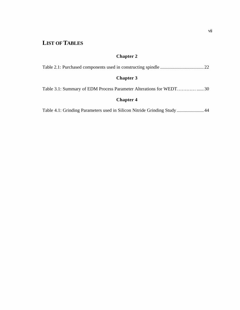
LIST OF TABLES
Chapter 2 Table 2.1: Purchased components used in constructing spindle ..................................... 22
Chapter 3 Table 3.1: Summary of EDM Process Parameter Alterations for WEDT………… ...... 30
Chapter 4 Table 4.1: Grinding Parameters used in Silicon Nitride Grinding Study ....................... 44
viii
LIST OF FIGURES
Chapter 1 Figure 1.1: Fuel injector with ceramic components.......................................................... 2 Figure 1.2: Evolution of ceramic grinding geometry........................................................ 3 Figure 1.3: Comparison between conventional profile grinding and formed profile grinding .............................................................................................. 4 Figure 1.4: Chart of hardness of work materials and grinding abrasives ......................... 5 Figure 1.5: Evolution of a single spark in the EDM process ............................................ 8 Figure 1.6: The wire EDM process ................................................................................. 10 Figure 1.7: Wire EDM of metal bond diamond wheel ................................................... 11 Figure 1.8: Procedure for formed electrode ED truing method ...................................... 13 Figure 1.9: Wire EDM truing/dressing method .............................................................. 14
Chapter 2 Figure 2.1: Final Spindle Configuration......................................................................... 18 Figure 2.2: (a) Snap-ring location (b) Brush adjuster and shunt wire ........................... 21 Figure 2.3: Features of spindle's shaft ............................................................................. 22 Figure 2.4: (a) Exploded view of components (b) Assembled components .................. 24 Figure 2.5: (a) setup for grinding hub mount taper (b) completed spindle ................... 26
Chapter 3 Figure 3.1: Profiles used for determining WEDT capability.......................................... 27 Figure 3.2: Spindle/Machine Setup for Metal Bond Diamond Wheel Profiling ............ 29 Figure 3.3: Diagram of WEDT gap ................................................................................ 31 Figure 3.4: Diagram of a spark cycle including both current and voltage ...................... 32 Figure 3.5: Diagram distinguishing between feedrate and wire speed ........................... 33 Figure 3.6: Peak-Valley profile....................................................................................... 34 Figure 3.7: Arc profile .................................................................................................... 36 Figure 3.8: Graph of form error with two different cutoff values used to filter the trace data........................................................................................ 39
Chapter 4 Figure 4.1: (a) creating groove into wheel by grinding silicon nitride (b) transfer groove to plastic wear block ........................................................................ 42 Figure 4.2: Silicon nitride grinding study setup on ELB grinder ................................... 43 Figure 4.3: Force and Power Data Acquisition System.................................................. 46 Figure 4.4: Horizontal and Vertical Grinding Forces ..................................................... 48 Figure 4.5: Diagram of grinding forces .......................................................................... 49 Figure 4.6: Tangential and Normal Grinding Forces ...................................................... 51
ix
Figure 4.7: Ratio of Tangential to Normal Grinding Forces .......................................... 53 Figure 4.8: Average and Peak-to-Valley Surface Roughness Values for the Ground Silicon Nitride Samples ............................................................ 55 Figure 4.9: Incremental and Actual Wheel Wear Depth................................................. 57
Chapter 5 Figure 5.1: (a) Drawing of segmented wheel (b) Balancing stand ................................ 61 Figure 5.2: Equipment used to prepare SEM samples .................................................... 63 Figure 5.3: SEM scans of the virgin WEDT wheel surface............................................ 66 Figure 5.4: A 40 µm gap clearance in WEDT process allows 30 µm diamond protrusion...................................................................................... 67 Figure 5.5: Stereo-SEM profile of WEDT virgin wheel surface with 29 µm protruding diamond ...................................................................................... 68 Figure 5.6: Stereo-SEM profile of WEDT virgin surface with 32 µm protruding diamond ....................................................................................... 69 Figure 5.7: Stereo-SEM profile of WEDT virgin wheel surface with 12.8 µm protruding diamond ........................................................................ 70 Figure 5.8: SEM scans of the wheel surface after light-grinding ................................... 72 Figure 5.9: Diagram of diamonds sheared during grinding ............................................ 74 Figure 5.10: Stereo-SEM profiles of lightly ground surface with 6 µm protruding diamond ..................................................................................... 75 Figure 5.11: Stereo-SEM profiles of lightly ground surface with 12 µm chip clearance.............................................................................................. 76 Figure 5.12: Mechanism that creates the wear cavity in front of the diamond face ....... 77 Figure 5.13: SEM scans of the wheel surface after heavy grinding ............................... 78 Figure 5.14: Stereo-SEM profiles of heavy ground wheel surface with 13 µm protruding diamond ......................................................................... 79 Figure 5.15: Stereo-SEM profiles of heavy ground surface with 4.6 µm protruding diamond and wear cavity.................................................... 80 Figure 5.16: (a) Rotary truing unit using a MBD wheel to dress the MBD wheel (b) SEM scan of the flat trued surface ........................................................ 81 Figure 5.17: SEM scans of 400 grit silicon carbide stick dressed wheel surface ........... 83 Figure 5.18: Description of dressing material removal zones ........................................ 84 Figure 5.19: Stereo-SEM profiles of stick dressed surface with a 12 µm protruding diamond .............................................................................. 85 Figure 5.20: Stereo-SEM profiles of stick dressed surface with a 6.5 µm protruding diamond .............................................................................. 86 Figure 5.21: Stereo-SEM profiles of stick dressed surface with a 7 µm protruding diamond and ridge .............................................................. 87 Figure 5.22: WEDT swarf from the truing of a Scepter 320 grit diamond wheel .......... 88
1
1 INTRODUCTION
Over the past two decade the use of ceramic components in engineering design
has increased steadily. This increase has also developed a need for improving tolerances
and material removal rates when grinding these ceramics. The ability to create a precise
form in a superabrasive wheel has been identified as one of these needs.
1.1 History of the Use of Ceramics in Diesel Engines
Applications of ceramics in diesel engines began in the late 1970’s. Research
work was carried out under U.S. Army research contracts to develop adiabatic and
minimum friction diesel engine that eliminate vulnerable cooling and liquid lubrication
systems for military vehicles. While these diesel concepts did not move beyond the
research stage, the programs highlighted the potential benefits that ceramics could
provide in production engines. The actual usage of ceramics in commercial diesel
engines evolved from these research efforts.
Due to the success of ceramic materials in selected applications, efforts are
continuing to utilize ceramics in specialized applications. Efforts are now being focused
on improving the cost effectiveness of precision ceramic components and improving the
processing capabilities. Silicon nitride, Silicon carbide, and Zirconia ceramics have been
commercially proven for wear applications in diesel engines.
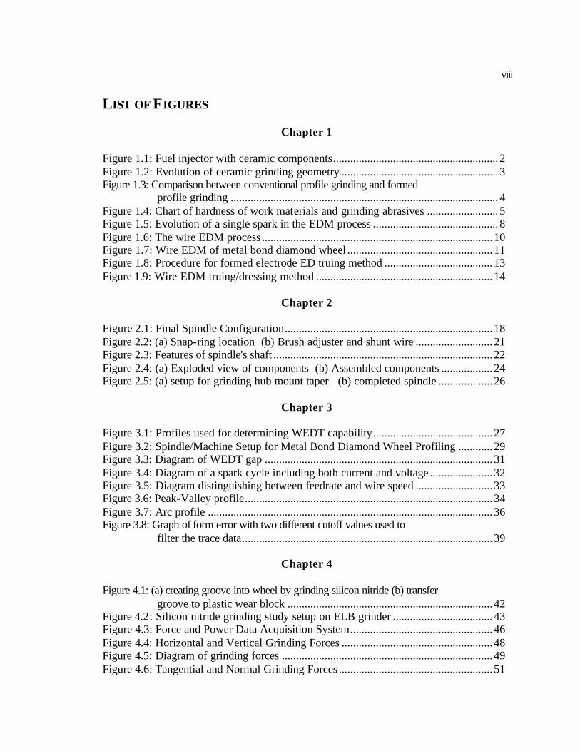
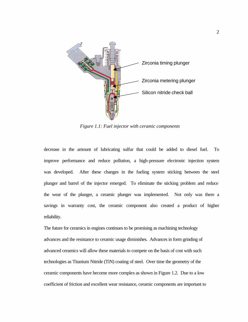
One example of success for the use of ceramics in the diesel engine is in the fuel
injector. Figure 1.1 shows a diesel fuel injector, which incorporated a silicon nitride
check ball and two plungers into the design. Due to EPA regulations, there was a
2
decrease in the amount of lubricating sulfur that could be added to diesel fuel. To
improve performance and reduce pollution, a high-pressure electronic injection system
was developed. After these changes in the fueling system sticking between the steel
plunger and barrel of the injector emerged. To eliminate the sticking problem and reduce
the wear of the plunger, a ceramic plunger was implemented. Not only was there a
savings in warranty cost, the ceramic component also created a product of higher
reliability.
The future for ceramics in engines continues to be promising as machining technology
advances and the resistance to ceramic usage diminishes. Advances in form grinding of
advanced ceramics will allow these materials to compete on the basis of cost with such
technologies as Titanium Nitride (TiN) coating of steel. Over time the geometry of the
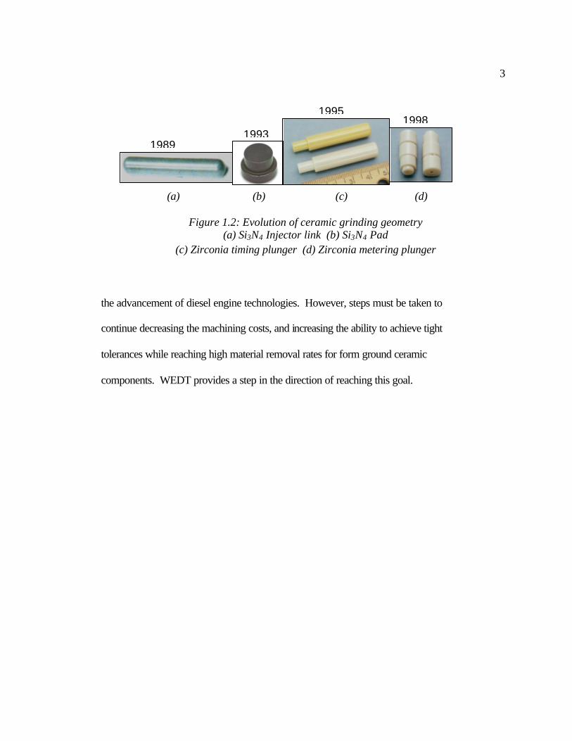
ceramic components have become more complex as shown in Figure 1.2. Due to a low
coefficient of friction and excellent wear resistance, ceramic components are important to
Figure 1.1: Fuel injector with ceramic components
Zirconia timing plunger Zirconia metering plunger
Silicon nitride check ball
3
the advancement of diesel engine technologies. However, steps must be taken to
continue decreasing the machining costs, and increasing the ability to achieve tight
tolerances while reaching high material removal rates for form ground ceramic
components. WEDT provides a step in the direction of reaching this goal.
(a) (b) (c) (d)
Figure 1.2: Evolution of ceramic grinding geometry (a) Si3N4 Injector link (b) Si3N4 Pad
(c) Zirconia timing plunger (d) Zirconia metering plunger
1989
1995 1998
1993
4
1.2 Form Grinding of Ceramics
Form grinding is used to reduce machining cost in many of cylindrical
components. Currently, there are limitations to the precision that can be achieved
through the forming and sintering of ceramics. Components require grinding to reach a
final shape, and to attain the required tolerances. The form grinding process offers
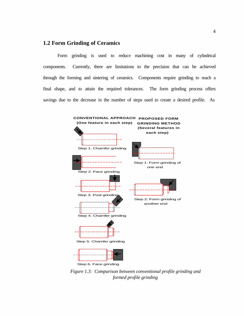
savings due to the decrease in the number of steps used to create a desired profile. As
Step 1. Chamfer grinding
CONVENTIONAL APPROACH
(One feature in each step)
Step 2. Face grinding
Step 3. Post grinding
Step 4. Chamfer grinding
Step 5. Chamfer grinding
Step 6. Face grinding
Step 1. Form grinding of
one end
Step 2. Form grinding of
another end
PROPOSED FORM
GRINDING METHOD
(Several features in
each step)
Figure 1.3: Comparison between conventional profile grinding and formed profile grinding
5
shown in Figure 1.3, a timing plunger can be machined using conventional or form
grinding methods. With the conventional machining approach it would take six grinding
setups to create the profile, while the form grinding method reduces this to two steps.
Although this saves both time and money during grinding, it also produces another issue
of creating a precise form in the grinding wheel.
The type of abrasive used in a grinding wheel is the determining factor on how
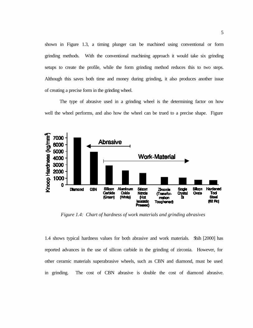
well the wheel performs, and also how the wheel can be trued to a precise shape. Figure
1.4 shows typical hardness values for both abrasive and work materials. Shih [2000] has
reported advances in the use of silicon carbide in the grinding of zirconia. However, for
other ceramic materials superabrasive wheels, such as CBN and diamond, must be used
in grinding. The cost of CBN abrasive is double the cost of diamond abrasive.
Figure 1.4: Chart of hardness of work materials and grinding abrasives
6
Therefore, diamond is often used as the abrasive in grinding wheels for ceramic
machining.
The three most popular grinding wheel bonding systems are: metal, resin, and
vitreous. The use of vitreous bond wheels have grown rapidly because of their advantage
of being trued and dressed simultaneously [Malkin, 1989]. However, the ability to create
µm-scale precision form truing of the vitreous bond is difficult due to the excess wear of
the truing tool [Shih, 1998]. Truing tool wear comes from the bonds high hardness and
from the force required to shear the diamonds. In order to true an abrasive wheel
effectively, the truing tool must be harder than the wheel being trued.
Precision forms are also unachievable with resin bond diamond wheels. This is
due to the inability of the low strength bond to support the diamonds during truing.
Metal bond wheels have good bond strength and wear characteristics, but create difficulty
in truing and dressing capabilities. The solution is to change the truing method not the
truing tool material [Shih, 2000]. WEDT can provide precise truing of metal bond
diamond grinding wheels, without high mechanical forces that cause truing tool wear.
7
1.3 Basic Principles of Electrical Discharge Machining
The following description explains the theory behind the generation of spark
erosion in the EDM process. While several theories of how EDM works have been
advanced over the years, most of the evidence supports the thermoelectric model. The
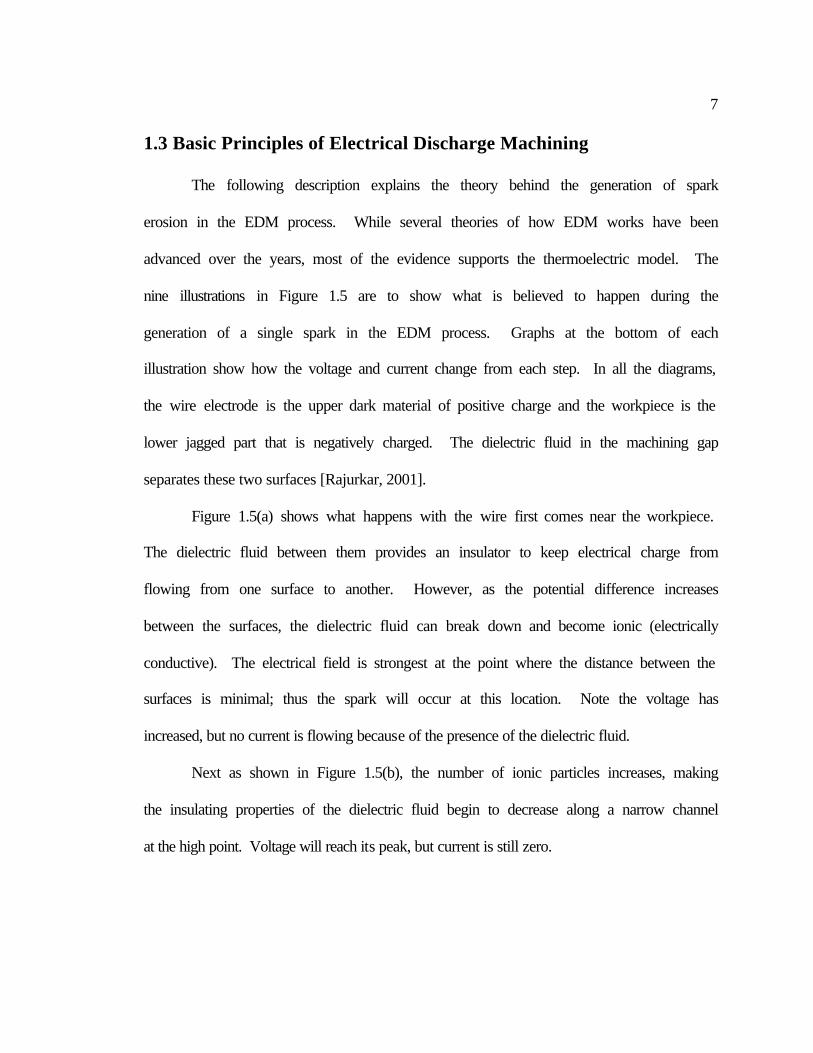
nine illustrations in Figure 1.5 are to show what is believed to happen during the
generation of a single spark in the EDM process. Graphs at the bottom of each
illustration show how the voltage and current change from each step. In all the diagrams,
the wire electrode is the upper dark material of positive charge and the workpiece is the
lower jagged part that is negatively charged. The dielectric fluid in the machining gap
separates these two surfaces [Rajurkar, 2001].
Figure 1.5(a) shows what happens with the wire first comes near the workpiece.
The dielectric fluid between them provides an insulator to keep electrical charge from
flowing from one surface to another. However, as the potential difference increases
between the surfaces, the dielectric fluid can break down and become ionic (electrically
conductive). The electrical field is strongest at the point where the distance between the
surfaces is minimal; thus the spark will occur at this location. Note the voltage has
increased, but no current is flowing because of the presence of the dielectric fluid.
Next as shown in Figure 1.5(b), the number of ionic particles increases, making
the insulating properties of the dielectric fluid begin to decrease along a narrow channel
at the high point. Voltage will reach its peak, but current is still zero.
8
Figure 1.5(c) shows that a current has established, causing the voltage to decrease.
Figure 1.5(d) shows that the voltage is continuing to drop as current continues to
increase. The heat builds up rapidly, causing some of the fluid, workpiece, and electrode
to vaporize. A discharge channel begins to form between the electrode and workpiece.
Figure 1.5(e) depicts a vapor bubble trying to expand outward, but a rush of ions
towards the discharge channel limits its expansion. The intense electro-magnetic field
that has built up in the channel attracts these ions.
(a) (b) (c)
(d) (e) (f)
(g) (h) (i) Figure 1.5: Evolution of a single spark in the EDM process [Rajurkar, 2001]
9
Figure 1.5(f) is during the end of the time when the voltage is on. Here the
current and voltage have stabilized. The heat and pressure inside the bubble have reach
maximum and some metal is being removed. The metal directly under the discharge
column is in molten state, but is held in place by the pressure of the vapor bubble.
Figures 1.5(g) 1.5(h), and 1.5(i) show what happens during the time when no
voltage is applied. Both voltage and current go to zero, which causes the temperature and
pressure to rapidly decrease in the vapor bubble causing it to collapse. This collapsing
bubble allows the molten material to be expelled from the surface of the workpiece.
Fresh dielectric fluid rushes in, flushing the debris away and quenching the surface of the
workpiece. Unexpelled molten metal solidifies back to the surface to form what is
known as the recast layer. This complete process of voltage on and off time comprises
the EDM spark cycle.
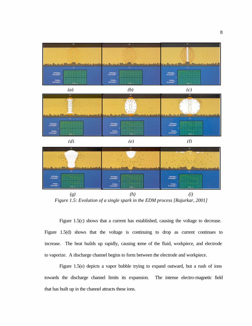
Wire EDM, as shown in Figure 1.6(a), uses a traveling brass wire, ranging from
0.02 to 0.40 mm in diameter, as the electrode. Continuous electrical sparks, Figure
1.6(b), are generated between the wire and workpiece for material removal. By using
computer numerical control, the thin wire is guided in the X and Y directions to cut a
precise shape in the workpiece.
10
1.4 Proposed Truing Method for Metal Bond Diamond Wheels
Currently, there are two methods for creating a metal bond diamond wheel. One
method uses a sintering process to combine metal powder and diamond to produce the
formed wheel. This process creates a thick layer of diamond onto a solid metal core.
Although effective in forming the wheel, currently the sintering process has limits on the
ability to create precise forms. The alternative method uses a single layer of diamond
electroplated on the surface of a preformed metal wheel [Malkin et al., 2000]. This
technology, although cost-effective, has limitations on form accuracy, usually in the 15 to
30 µm range, and surface finish, typical above 0.3 µm average roughness. For parts that
do not need µm-scale precision and fine surface finish, grinding with electroplated single-
layer diamond wheels is the preferred choice.
(a) (b)
Figure 1.6: The wire EDM process, (a) conventional 2D wire EDM operation, (b) enlarged view of the wire and workpiece.
Electricalsparks betweengap to removework-material
Travelling wireTravelling wire
XY
Workpiece
Voltage pulseto generateelectricalsparks
11
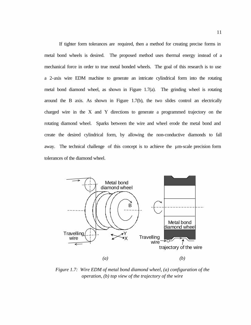
If tighter form tolerances are required, then a method for creating precise forms in
metal bond wheels is desired. The proposed method uses thermal energy instead of a
mechanical force in order to true metal bonded wheels. The goal of this research is to use
a 2-axis wire EDM machine to generate an intricate cylindrical form into the rotating
metal bond diamond wheel, as shown in Figure 1.7(a). The grinding wheel is rotating
around the B axis. As shown in Figure 1.7(b), the two slides control an electrically
charged wire in the X and Y directions to generate a programmed trajectory on the
rotating diamond wheel. Sparks between the wire and wheel erode the metal bond and
create the desired cylindrical form, by allowing the non-conductive diamonds to fall
away. The technical challenge of this concept is to achieve the µm-scale precision form
tolerances of the diamond wheel.
(a) (b)
Figure 1.7: Wire EDM of metal bond diamond wheel, (a) configuration of the operation, (b) top view of the trajectory of the wire
Travellingwire X
Y
B
Metal bonddiamond wheel
trajectory of the wire
Travellingwire
Metal bonddiamond wheel
12
1.5 Literature Review
Much research has been conducted on the EDM process over the past two
decades. However, much of the work has been on developing better power sources,
discharge patterns, and improving gap conditions. Most of the work being conducted
with EDM truing has been conducted in Japan and China.
One of the first papers that discussed EDM truing was in 1987 by Suzuki et al.
[1987]. This paper considers both wire and electrode EDM of metal bonded wheels. It
discusses the problems associated with traditional truing of the hard metal bonded
wheels. This paper shows evidence for a reduction in grinding forces, higher grinding
ratio, and the realization of the ability to form wheels using EDM truing. The paper
concludes with this statement, “The authors believe that this method will contribute to the
development of grinding work with super abrasive wheels”. The details of the two truing
methods die sinker and wire EDM, are summarized in the following sections.
1.5.1 Die Sinker EDM Truing Method
In die sinker EDM a graphite, copper, or tungsten electrode is shaped to perform
the EDM process. The electrode is machined using conventional machining, such as
milling and turning. Then the shaped conductive electrode is used to erode the contour
into a workpiece through electrical sparks. A major disadvantage to this method is
electrode wear, which creates error in the final component. The advantage is that
machining occurs over the entire electrode surface, creating a high machining efficiency.
On the contrary, with wire EDM the machining occurs at a single point, which is not as
13
efficient. However, due to electrode wear in the Die Sinker configuration, the ability to
create precise forms is in question.
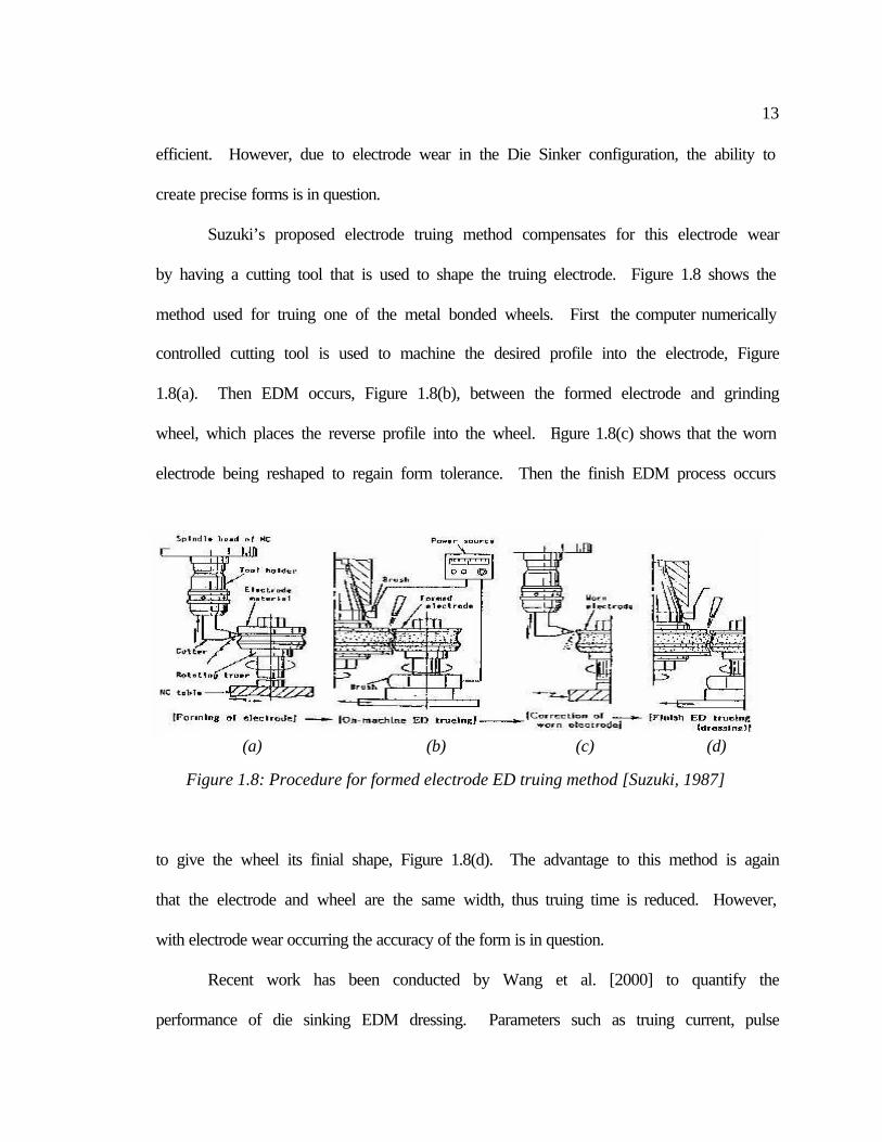
Suzuki’s proposed electrode truing method compensates for this electrode wear
by having a cutting tool that is used to shape the truing electrode. Figure 1.8 shows the
method used for truing one of the metal bonded wheels. First the computer numerically
controlled cutting tool is used to machine the desired profile into the electrode, Figure
1.8(a). Then EDM occurs, Figure 1.8(b), between the formed electrode and grinding
wheel, which places the reverse profile into the wheel. Figure 1.8(c) shows that the worn
electrode being reshaped to regain form tolerance. Then the finish EDM process occurs
to give the wheel its finial shape, Figure 1.8(d). The advantage to this method is again
that the electrode and wheel are the same width, thus truing time is reduced. However,
with electrode wear occurring the accuracy of the form is in question.
Recent work has been conducted by Wang et al. [2000] to quantify the
performance of die sinking EDM dressing. Parameters such as truing current, pulse
(a) (b) (c) (d)
Figure 1.8: Procedure for formed electrode ED truing method [Suzuki, 1987]
14
frequency, pulse duration, wheel speed, and wheel eccentricity where characterized on
how truing efficiency was affected. However, the relationship between form accuracy
and these parameters was never developed. This is in part due to the fact that form
errors, in this rotary die sinking EDM, are dominated by electrode wear.
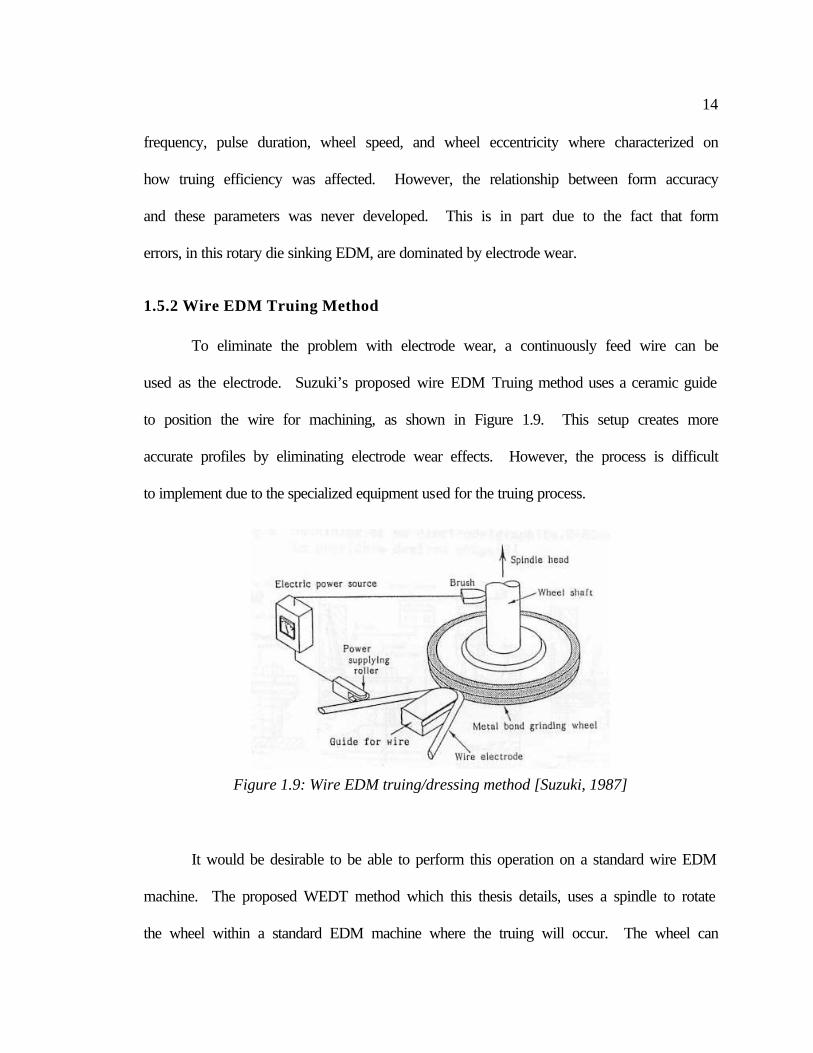
1.5.2 Wire EDM Truing Method
To eliminate the problem with electrode wear, a continuously feed wire can be
used as the electrode. Suzuki’s proposed wire EDM Truing method uses a ceramic guide
to position the wire for machining, as shown in Figure 1.9. This setup creates more
accurate profiles by eliminating electrode wear effects. However, the process is difficult
to implement due to the specialized equipment used for the truing process.
It would be desirable to be able to perform this operation on a standard wire EDM
machine. The proposed WEDT method which this thesis details, uses a spindle to rotate
the wheel within a standard EDM machine where the truing will occur. The wheel can
Figure 1.9: Wire EDM truing/dressing method [Suzuki, 1987]
15
then be transferred to a grinding machine to perform the grinding operation.
Modifications must also be made in the programming of the discharge properties.
1.5.3 ELectrolytic In-process Dressing (ELID) method
FUJI Die Company has developed cast iron bonded diamond wheels [Nakagawa,
1984] that are capable of being electrolytic in-process dressed, ELID. Much of this
research as been conducted by the Materials Fabrication Laboratory in Japan by Dr.
Hitoshi Ohmori [Qian et. al, 2000]. This research claims, “Dressing by electrical
discharge is a good method, but it is difficult to conduct on-line dressing.” As implied by
the name ELID is only a dressing method, EDM was first used to true the wheel, then
ELID is used to continuously dress the wheel during grinding operations.
Ohmori claims that ELID has so far served as the most successful dressing
method for metal bond wheels in precision surface grinding [Ohmori, 1996]. Although
this method does create good surface finish, the ability to dress precise forms has not
been shown. All of the papers reviewed, including Zhang’s internal grinding [Zhang,
2000], incorporate ELID for dressing a straight profiled wheel. It is important to recall
that this process is unable to true the metal bond wheel. ELID is used only as a dressing
process; EDM is still required to true the wheel. If ELID proves to be capable of dressing
precise formed metal bond diamond wheels, precise EDM truing will still be required to
form the wheel.
16
1.6 Patent Search
Patentability of the WEDT process is a possibility, due to its uniqueness of using
a standard wire EDM machine. All of the Japanese patents by Mizukawa et al. [1992],
Shichizawa [1993], Oku et al. [1984], and Nakagawa et al. [1989] deal with EDM truing
using a die sinking rotary electrode. No patents could be found which use a standard
wire EDM machine, to perform the truing operations. It is important to note that this
process is valuable for its flexibility within the machine shop; it is not intended for
production grinding. In this case the EDM truing unit would be integrated with the
grinding machine to eliminate removal of the grinding wheel for truing. It also becomes
valuable in an experimental environment for creating prototypes for testing purposes.
The only equipment required to perform the truing is a precise spindle and use of a
traditional EDM machine.
17
2 SPINDLE DESIGN
One of the initial challenges in the research was to design a spindle that would
rotate the wheel inside the EDM machine. When the research was first underway, it was
desired to purchase an industrial “off the shelf” spindle which could be modified in order
to mount the wheel. Spindle’s offered by System 3R were considered, but the amount of
modification required in order to mount the wheel to the spindle was substantial.
Another drawback was high price. Thus, the first step was to design and build a spindle
that could meet the defined requirements.
Corrosive Environment – This spindle would have to operate in the presence of
deionized water. Therefore, all components that will be in direct contact with the water
will require corrosive resistant materials. While those components that cannot perform in
the presence of water, like the motor, will have to be shielded in the design.
Electrical Environment – The metal bond wheel must be electrically grounded to the
machine for the EDM sparking to occur. Thus, the spindle must be able to carry high
electrical current to ground. Also any gaps within this path could become a potential
location where electrical spark could occur.
Tight Tolerances – In order to obtain the µm tolerances desired in the profile on the
wheel, the spindle must also be up to this standard. Goals of robustness and high
precision were at the forefront during the design and manufacturing of the spindle. Also
spindle vibrations must be minimized to achieve this µm tolerance.
Geometry Restraints and Flexibility – The most obvious requirement in geometry is a
method for mounting the wheel on the spindle in a repeatable manner. Also the wheel
18
must be able to be placed on a grinding machine in the same fashion. The design should
also be able to except varies grinding wheel diameters. A compact spindle must be
accomplished to avoid interference with the EDM machine.
2.1 Overview of Spindle Design
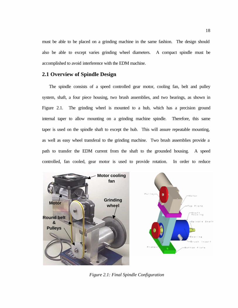
The spindle consists of a speed controlled gear motor, cooling fan, belt and pulley
system, shaft, a four piece housing, two brush assemblies, and two bearings, as shown in
Figure 2.1. The grinding wheel is mounted to a hub, which has a precision ground
internal taper to allow mounting on a grinding machine spindle. Therefore, this same
taper is used on the spindle shaft to except the hub. This will assure repeatable mounting,
as well as easy wheel transferal to the grinding machine. Two brush assemblies provide a
path to transfer the EDM current from the shaft to the grounded housing. A speed
controlled, fan cooled, gear motor is used to provide rotation. In order to reduce
Grinding wheel
Motor cooling fan
Motor
Round belt &
Pulleys
Figure 2.1: Final Spindle Configuration
19
vibrations in rotational transmission, a smooth round belt and pulley system was
implemented.
Two deep-groove ball bearings with silicon nitride balls and stainless steel races were
used to support the shaft. These bearings provide corrosive resistance to the deionized
water, while isolating the bearings from the current flow. All other spindle components
are made of water corrosion resistant materials, such as stainless steel, plastic, or
aluminum. The finished spindle met the precision requirements by achieving a runout of
less than 1 µm.
2.2 Spindle Components
In order to create the spindle some components were purchased from a supplier,
while others were machined at Cummins Technical Center. The following two sections
discuss the reasoning behind the component selection.
2.2.1 Purchased Components
To rotate the spindle a DC permanent magnet motor was chosen, due to low cost
and excellent speed control. Also since gear motors allow rotation to be transferred along
an axis other than the motor axis, clearance between the motor and EDM head was easy
to maintain. Dayton also supplies a direct mount speed controller for the gearmotor,
which allows speed control form 0 to 89rpm in twenty increments.
Several types of belts were considered for this application. A timing belt would
provide a no-slip condition but the power transmission is somewhat “incremental” due to
the mating of the teeth. A V-belt would have been effective but could create potential
20
trouble in installation and would require a belt tensioner to adjust the belt. To eliminate
this extra component and to simplify the assembly, a polyethylene round belt was used.
The belt is stretchable which makes installation easy and no tensioner is required. Also
the belt can be cut to length and joined together with aluminum connectors.
The bearing selection was the key to the success of the spindle. They had to be
rigid (preloaded) and also withstand the corrosive environment. Both plastic and
stainless steel bearings were considered. Steel would provide a rigid support, which is
needed to obtain the tight tolerances. However, with steel bearings the concern was
about the balls causing spark erosion on the races. Current must flow from the wheel,
through the shaft and bearings into the grounded housing. If the balls are not preloaded
firmly against the races then the current will jump the gap and begin to erode the balls
and pit the races. Also the surface area of contact is very small thus creating a resistance
to current flow, which is not good for the EDM process.
A solution is to prevent current from flowing through the bearings, by making the
balls insulators instead of a conductors, thus ceramic bearings were incorporated. To
ensure that the deionized water could not get into the sealed bearings, additional oil seals
were used to seal the bearings from the environment. A snap ring, Figure 2.2(a), was
used to assure bearing/shaft alignment and also to prevent axial motion of the shaft.
As previously mentioned there must be a conductive path between the wheel and
ground. Since the ball bearings are non-conductive, a brush assembly was used to carry
the current from the shaft to the housing. A shunt on the brushes was used, since the
small diameter loading spring would not be able to handle the heavy current flow created
21
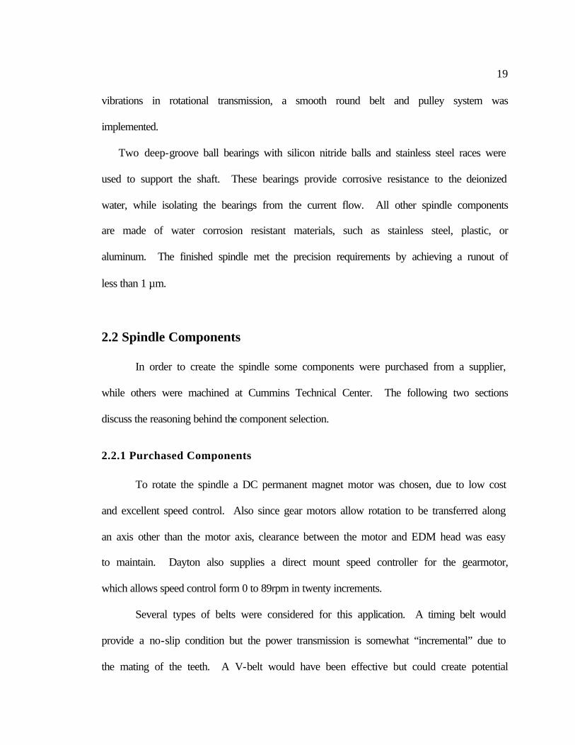
by EDM. The brush geometry was rectangular to keep it from cantering in the slot as it
rubs against the shaft. This required some wire EDM machining to create the square
rectangle to receive the brush. Also an additional insert was added to allow adjustment of
brush force on the shaft, as shown in Figure 2.2(b).
One concern in the design was how to ensure that repeatable positioning of the
grinding wheel between the EDM and grinding machines. This is due to the fact that
profiling would have to be done in an EDM machine, but then moved to a grinding
machine to perform any machining test. Grinding wheels are typically mounted using a
tapered hub, which assures repeatable mounting. This same tapered hub mount was used
to position the wheel on the spindle shaft. Table 2.1 gives a summary of all the
purchased components, the supplier, part number, and a brief summary of the
specifications.
(a) (b)
Figure 2.2: (a) Snap-ring location (b) Brush adjuster and shunt wire
Snap ring
Shunt wire
Brush adjuster
22
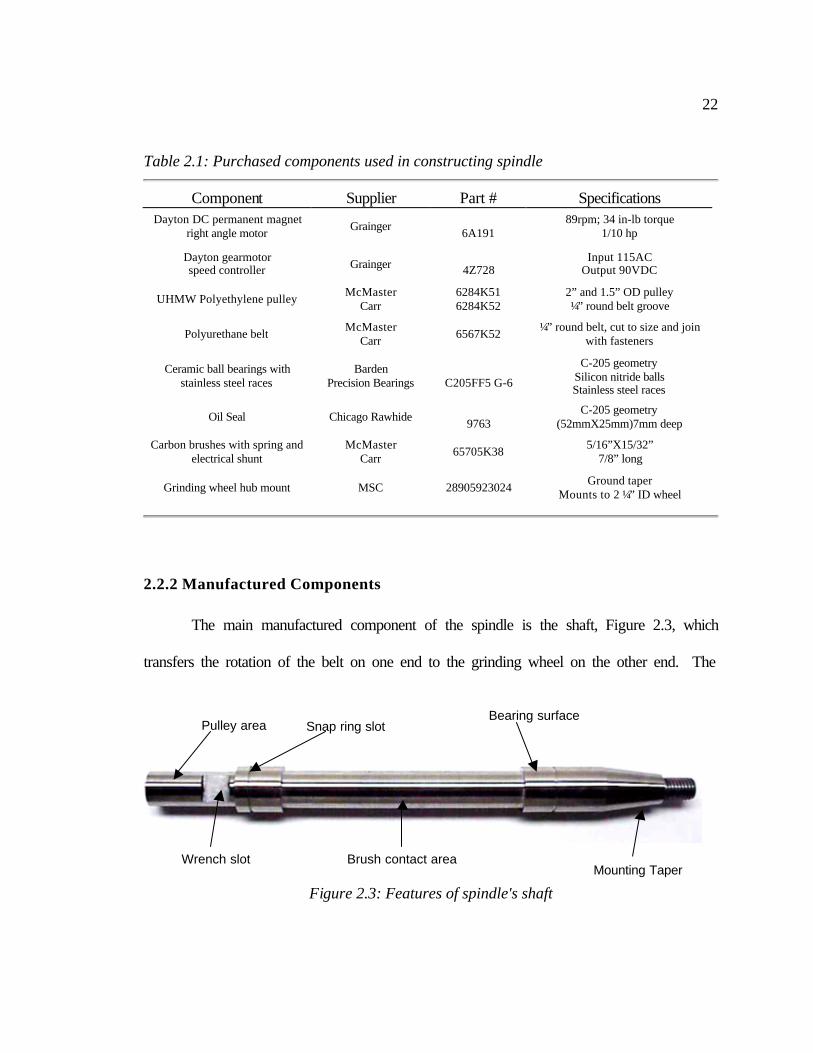
Table 2.1: Purchased components used in constructing spindle
Component Supplier Part # Specifications
Dayton DC permanent magnet right angle motor Grainger
6A191 89rpm; 34 in-lb torque
1/10 hp
Dayton gearmotor speed controller Grainger
4Z728 Input 115AC
Output 90VDC
UHMW Polyethylene pulley McMaster Carr
6284K51 6284K52
2” and 1.5” OD pulley ¼” round belt groove
Polyurethane belt McMaster Carr 6567K52 ¼” round belt, cut to size and join
with fasteners
Ceramic ball bearings with stainless steel races
Barden Precision Bearings
C205FF5 G-6
C-205 geometry Silicon nitride balls Stainless steel races
Oil Seal Chicago Rawhide 9763
C-205 geometry (52mmX25mm)7mm deep
Carbon brushes with spring and electrical shunt
McMaster Carr 65705K38 5/16”X15/32”
7/8” long
Grinding wheel hub mount MSC 28905923024 Ground taper Mounts to 2 ¼” ID wheel
2.2.2 Manufactured Components
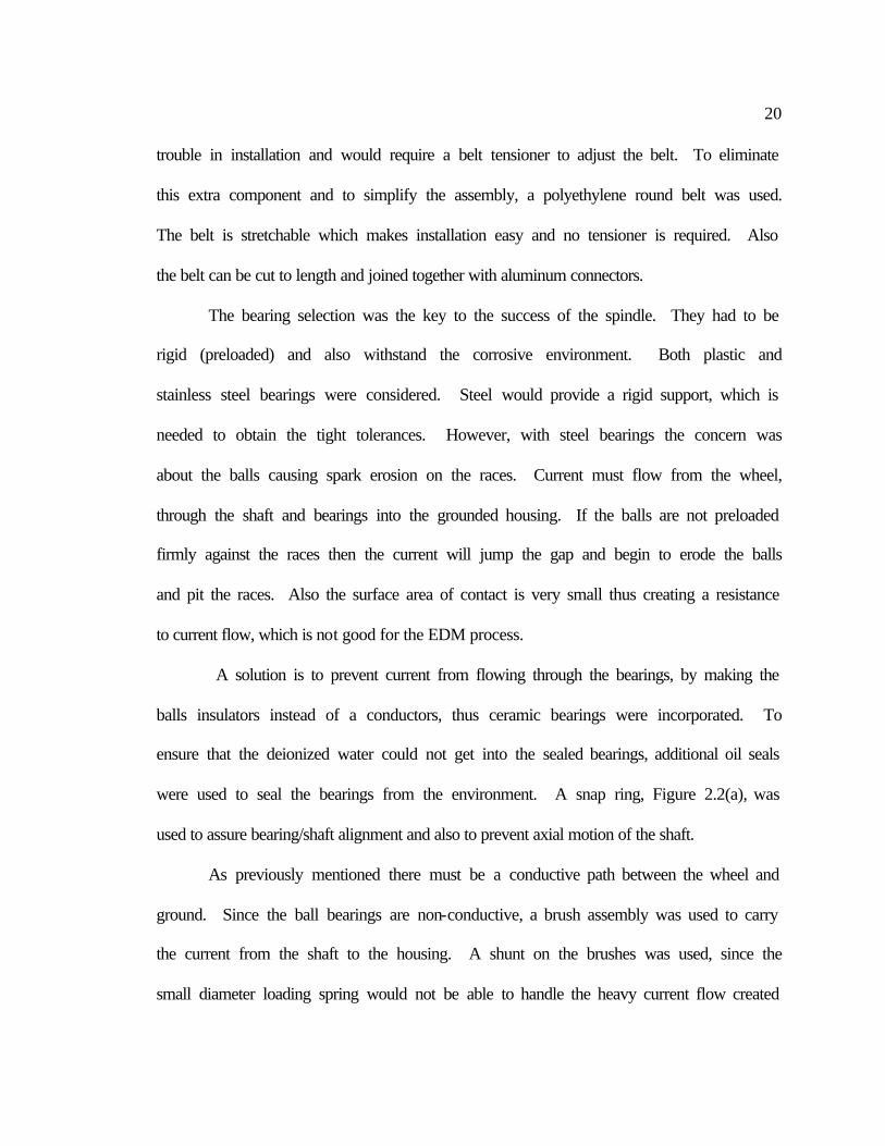
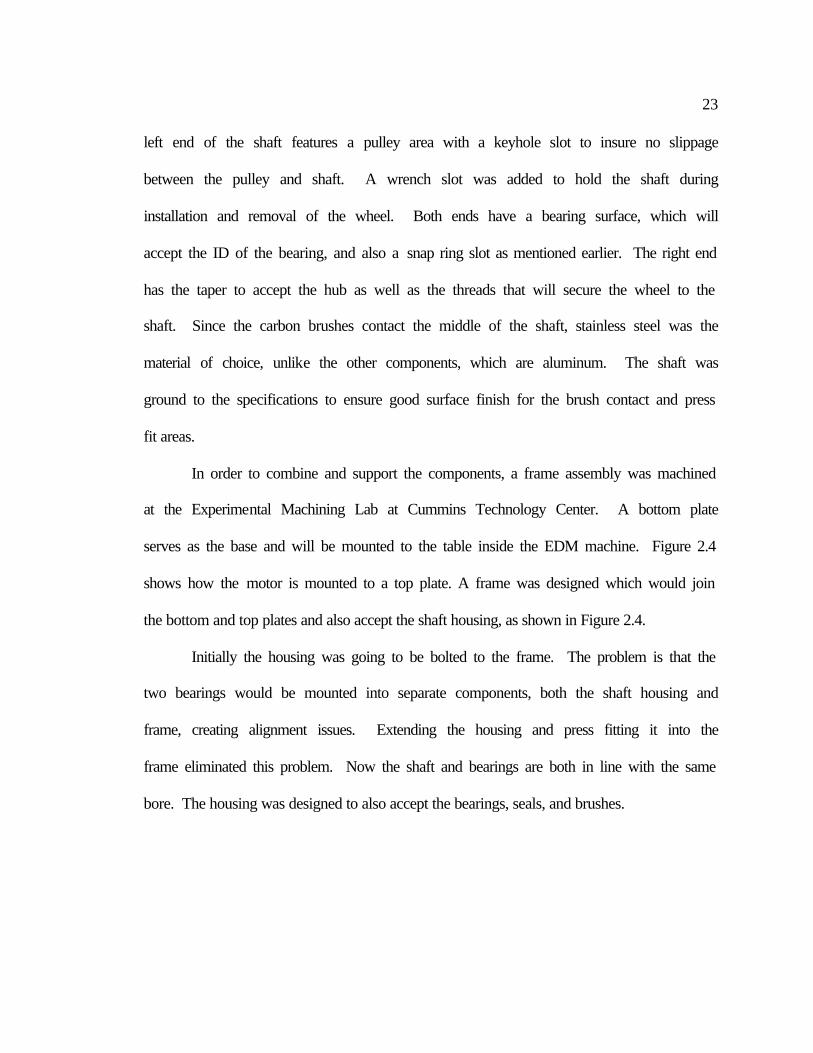
The main manufactured component of the spindle is the shaft, Figure 2.3, which
transfers the rotation of the belt on one end to the grinding wheel on the other end. The
Snap ring slot
Wrench slot
Pulley area
Brush contact area
Bearing surface
Figure 2.3: Features of spindle's shaft
Mounting Taper
23
left end of the shaft features a pulley area with a keyhole slot to insure no slippage
between the pulley and shaft. A wrench slot was added to hold the shaft during
installation and removal of the wheel. Both ends have a bearing surface, which will
accept the ID of the bearing, and also a snap ring slot as mentioned earlier. The right end
has the taper to accept the hub as well as the threads that will secure the wheel to the
shaft. Since the carbon brushes contact the middle of the shaft, stainless steel was the
material of choice, unlike the other components, which are aluminum. The shaft was
ground to the specifications to ensure good surface finish for the brush contact and press
fit areas.
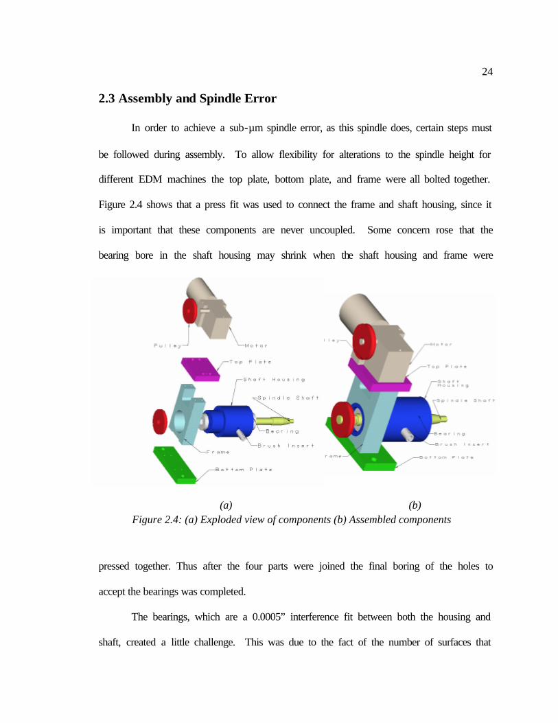
In order to combine and support the components, a frame assembly was machined
at the Experimental Machining Lab at Cummins Technology Center. A bottom plate
serves as the base and will be mounted to the table inside the EDM machine. Figure 2.4
shows how the motor is mounted to a top plate. A frame was designed which would join
the bottom and top plates and also accept the shaft housing, as shown in Figure 2.4.
Initially the housing was going to be bolted to the frame. The problem is that the
two bearings would be mounted into separate components, both the shaft housing and
frame, creating alignment issues. Extending the housing and press fitting it into the
frame eliminated this problem. Now the shaft and bearings are both in line with the same
bore. The housing was designed to also accept the bearings, seals, and brushes.
24
2.3 Assembly and Spindle Error
In order to achieve a sub-µm spindle error, as this spindle does, certain steps must
be followed during assembly. To allow flexibility for alterations to the spindle height for
different EDM machines the top plate, bottom plate, and frame were all bolted together.
Figure 2.4 shows that a press fit was used to connect the frame and shaft housing, since it
is important that these components are never uncoupled. Some concern rose that the
bearing bore in the shaft housing may shrink when the shaft housing and frame were
pressed together. Thus after the four parts were joined the final boring of the holes to
accept the bearings was completed.
The bearings, which are a 0.0005” interference fit between both the housing and
shaft, created a little challenge. This was due to the fact of the number of surfaces that
(a) (b) Figure 2.4: (a) Exploded view of components (b) Assembled components
25
must mate at the same time. First the frame was heated to 450°F in an oven to get the
required thermal expansion. Meanwhile, the shaft was submerged in liquid nitrogen for
about 10 minutes to get the required thermal shrinkage. Then the bearings, shaft, and
housing were pressed together and allowed to stabilize back to room temperature
overnight to create the press fit.
Spindle error was measured using a shaded pole inductor measuring device. The
flat surface, where the bearings are mounted, was measured which gave a spindle error of
about 2 to 3 µm peak-to-valley. When the error was measured on the ground tapered
surface, spindle runout was 38 to 40 µm peak-to-valley. The wheel hub taper was ground
on a different setup than was the shaft and bearing surfaces. Therefore, the taper’s axis
of rotation and that of rest of the shaft are different. To compensate for this error, the
final taper on the shaft was performed with the shaft mounted in the bearings and
housing.
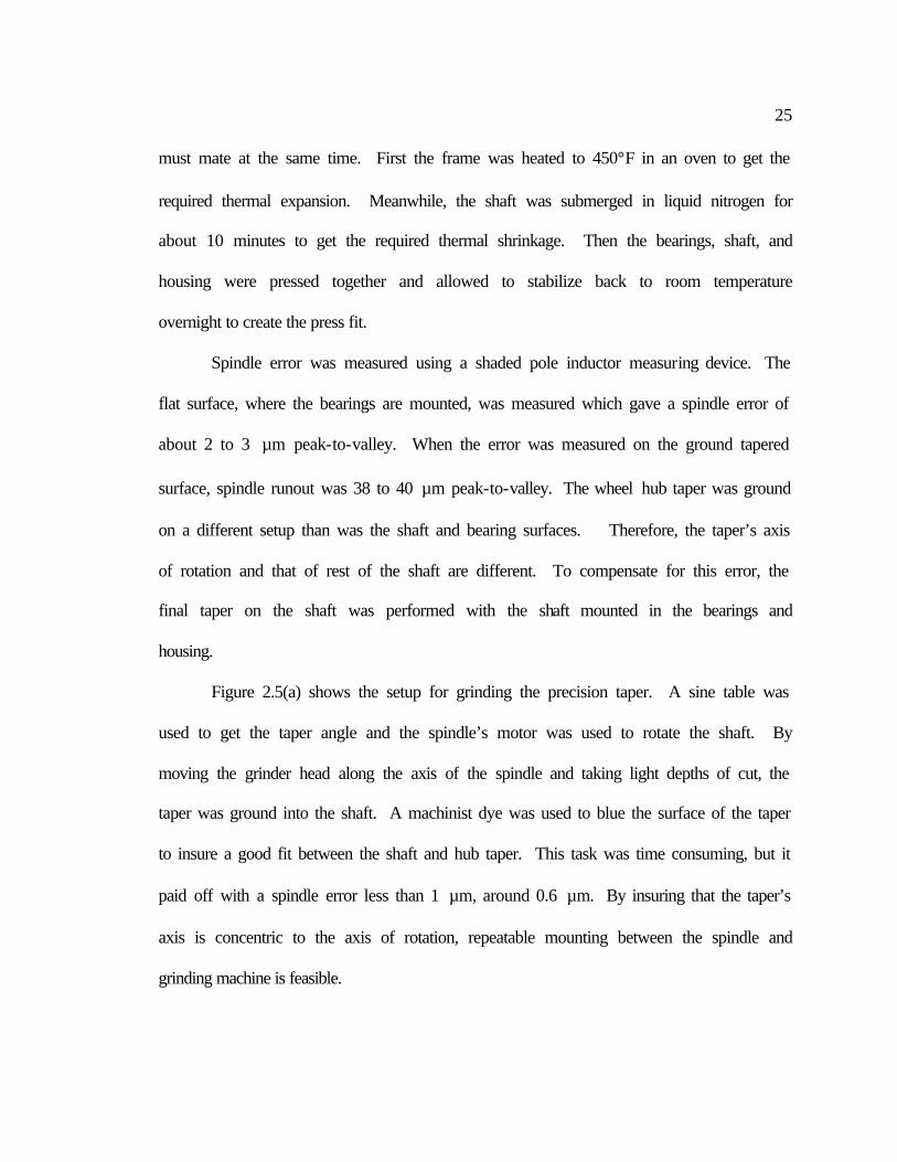
Figure 2.5(a) shows the setup for grinding the precision taper. A sine table was
used to get the taper angle and the spindle’s motor was used to rotate the shaft. By
moving the grinder head along the axis of the spindle and taking light depths of cut, the
taper was ground into the shaft. A machinist dye was used to blue the surface of the taper
to insure a good fit between the shaft and hub taper. This task was time consuming, but it
paid off with a spindle error less than 1 µm, around 0.6 µm. By insuring that the taper’s
axis is concentric to the axis of rotation, repeatable mounting between the spindle and
grinding machine is feasible.
26
Also the motor on the spindle got warm after continuous usage. The motor sets
inside the EDM machine were the air is stagnant, thus the problem could be resolved by
installing a small computer cooling fan, Figure 2.5(b), to create air flow over the body of
the motor.
Once the brushes were installed resistance between the shaft and housing was
checked with a multi-meter to ensure adequate shaft/brush contact. The resistance was
only about 2Ω, which creates an ideal situation of low resistance to current flow for
EDM. While using the spindle it was noted that an oxide layer did form between the
brushes and the surface of the shaft. A thin coat of electrically conductive grease
between the two surfaces solved this problem.
(a) (b)
Figure 2.5: (a) setup for grinding hub mount taper (b) completed spindle
27
3 SETUP FOR WIRE ELECTRICAL DISCHARGE TRUING AND
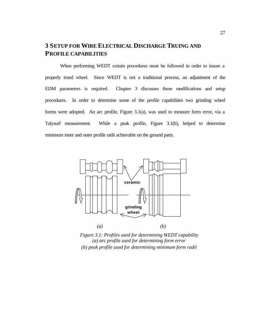
PROFILE CAPABILITIES When performing WEDT certain procedures must be followed in order to insure a
properly trued wheel. Since WEDT is not a traditional process, an adjustment of the
EDM parameters is required. Chapter 3 discusses these modifications and setup
procedures. In order to determine some of the profile capabilities two grinding wheel
forms were adopted. An arc profile, Figure 3.1(a), was used to measure form error, via a
Talysurf measurement. While a peak profile, Figure 3.1(b), helped to determine
minimum inner and outer profile radii achievable on the ground parts.
grinding wheel
ceramic
(a) (b)
Figure 3.1: Profiles used for determining WEDT capability (a) arc profile used for determining form error
(b) peak profile used for determining minimum form radii
28
3.1 Performing WEDT
One advantage of WEDT is that it performed using a traditional wire EDM
machine. This makes the process desirable, due to the fact that no new machinery is
required. However, since the WEDT is not a traditional EDM procedure, additional
knowledge is required to perform the process. The following two sections discuss the
WEDT setup procedures, as well as the EDM process parameters.
3.1.1 Setup Procedures
First the wheel/hub assembly is bolted to the spindle shaft. Then the complete
spindle/wheel assembly is bolted to the worktable inside the EDM machine, which serves
as the electrical ground. A dial indicator is then used to insure that the spindle and
machine’s axes are aligned. In order to determine orientation of the workpiece relative to
wire, an edge find command was executed. The wire moves in slowly until it detects the
electrical ground of the wheel. By doing this in both directions, the exact location of an
edge of the wheel can be defined. The wire is then backed away from the edge about
2.54 mm in order to allow sufficient space for the machine to automatically rethread the
wire in the event of a wire break. This is the start point from which machining will
begin.
Normally, the workpiece in EDM machining would be submerged in a dielectric
bath for improved flushing and temperature control. However, if this process is
determined feasible and the technology was integrated in a grinding machine, it would be
impossible to submerge a grinding wheel on a grinder. Thus it is better to develop the
technology using only a jet or mist of water to provide the dielectric fluid. Flushing was
29
not an issue, since the wire is only working on the surface, and is not buried within the
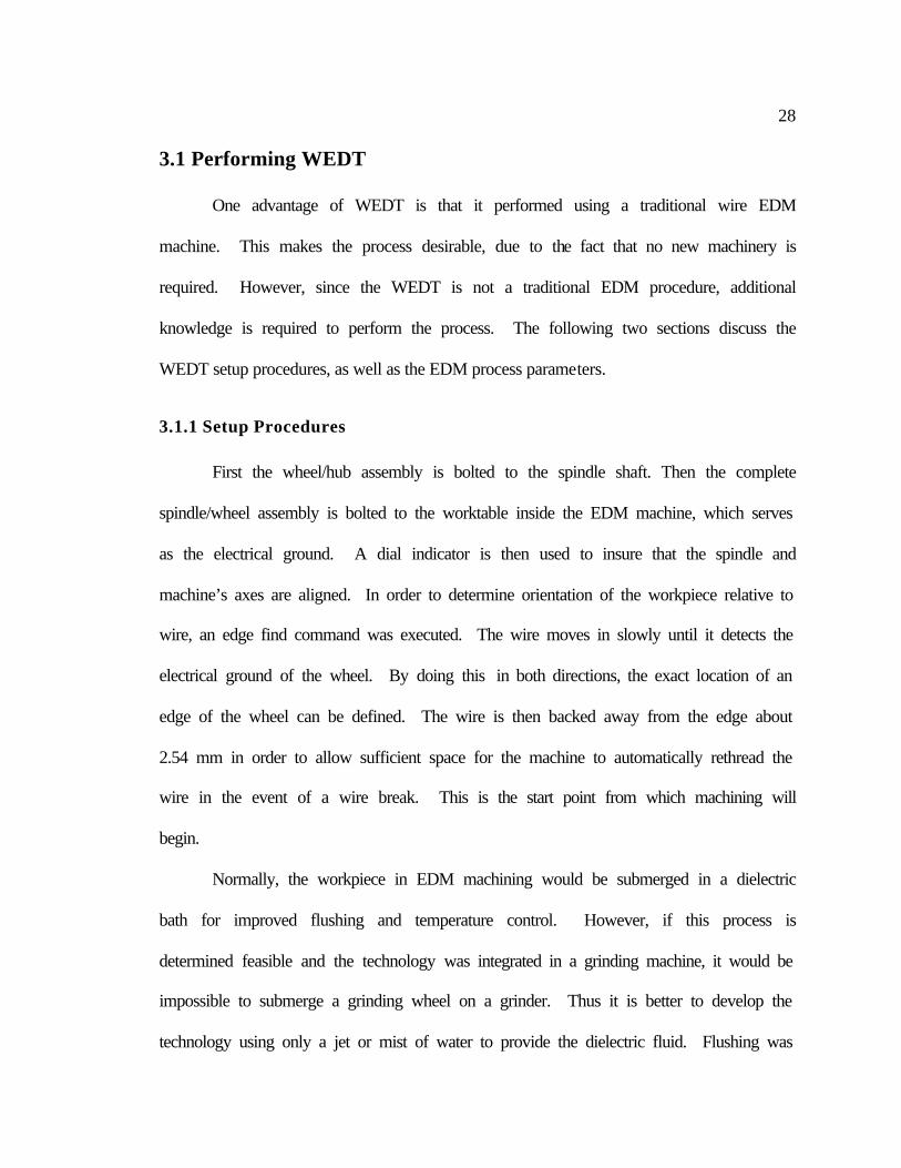
material. Jet flushing can be seen during WEDT in Figure 3.2. A mist of high-pressure
water could also provide adequate flushing, however this was not investigated in this
study.
Rotation of the wheel was set to make the surface velocity of the wheel match that
of the spooling wire, as seen in Figure 3.2. The relative velocity between the two
surfaces is minimized. Wheel rotation in the opposite was also tested, which lead to
frequent wire breaks.
3.1.2 Process Parameters for WEDT
Since WEDT of a metal bond diamond wheel is not a traditional EDM process,
predetermined EDM parameters are not established. Through an understanding of how
the parameters interact and trial and error the parameters are adjusted to perform EDM
Figure 3.2: Spindle/Machine Setup for MBD Wheel Profiling
spooling wire
direction
wheel rotation
30
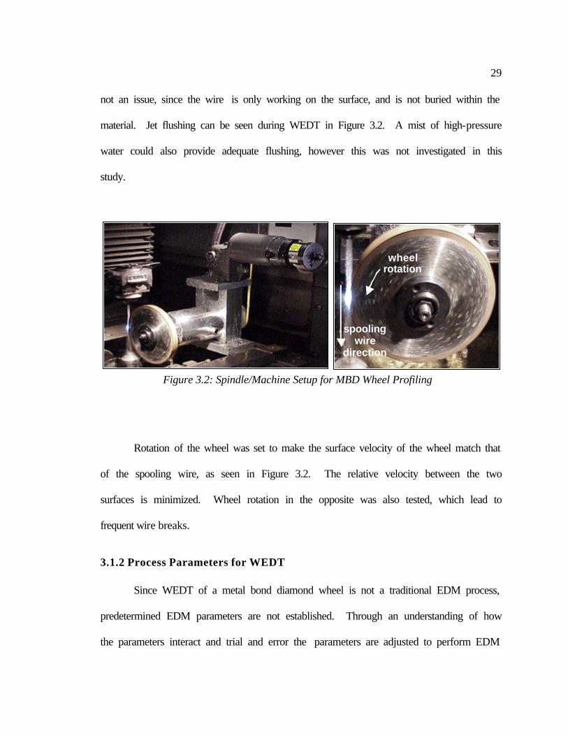
truing. Due to the fact that the metal matrix of the grinding wheel is about 80% copper, a
predetermined program for ¼” copper was selected to be modified. There are six major
EDM parameters that are important and are summarized in Table 3.1. A brief discussion
on why four of these parameters are altered from the base program follows.
Table 3.1: Summary of EDM Process Parameter Alterations for WEDT
EDM Process Parameters Baseline ¼” copper settings WEDT settings
Gap Voltage (V) 35 70
Spark Cycle (µs) 19 32
On time (µs) 12 12
Feedrate (mm/min) 6.6 0.254
Wire Speed (mm/sec) 12 25
Wire Tension (grams) 1800 1800
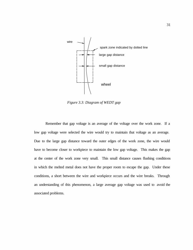
The gap voltage is the nominal voltage in the gap between the wire and
workpiece. Thus the further apart the wire and workpiece are the higher the gap voltage,
and vise versa. By increasing the gap voltage from 35 to 70 V, the distance between the
wire and wheel is increased. Since the workpiece is circular and the wire is straight, the
gap distance varies across the work zone, as shown in Figure 3.3.
31
Remember that gap voltage is an average of the voltage over the work zone. If a
low gap voltage were selected the wire would try to maintain that voltage as an average.
Due to the large gap distance toward the outer edges of the work zone, the wire would
have to become closer to workpiece to maintain the low gap voltage. This makes the gap
at the center of the work zone very small. This small distance causes flushing conditions
in which the melted metal does not have the proper room to escape the gap. Under these
conditions, a short between the wire and workpiece occurs and the wire breaks. Through
an understanding of this phenomenon, a large average gap voltage was used to avoid the
associated problems.
Figure 3.3: Diagram of WEDT gap
large gap distance
small gap distance
spark zone indicated by dotted line
wheel
wire
32
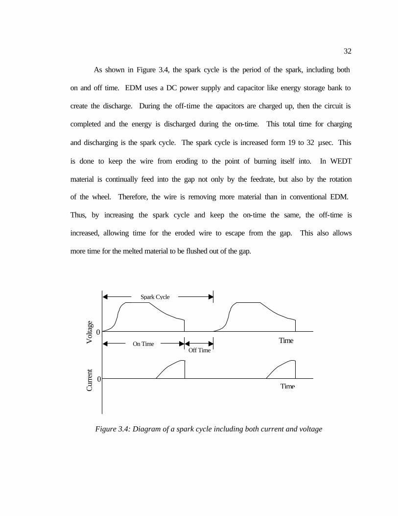
As shown in Figure 3.4, the spark cycle is the period of the spark, including both
on and off time. EDM uses a DC power supply and capacitor like energy storage bank to
create the discharge. During the off-time the capacitors are charged up, then the circuit is
completed and the energy is discharged during the on-time. This total time for charging
and discharging is the spark cycle. The spark cycle is increased form 19 to 32 µsec. This
is done to keep the wire from eroding to the point of burning itself into. In WEDT
material is continually feed into the gap not only by the feedrate, but also by the rotation
of the wheel. Therefore, the wire is removing more material than in conventional EDM.
Thus, by increasing the spark cycle and keep the on-time the same, the off-time is
increased, allowing time for the eroded wire to escape from the gap. This also allows
more time for the melted material to be flushed out of the gap.
0
0
Cur
rent
Vol
tage
Spark Cycle
On Time Off Time
Figure 3.4: Diagram of a spark cycle including both current and voltage
Time
Time
33
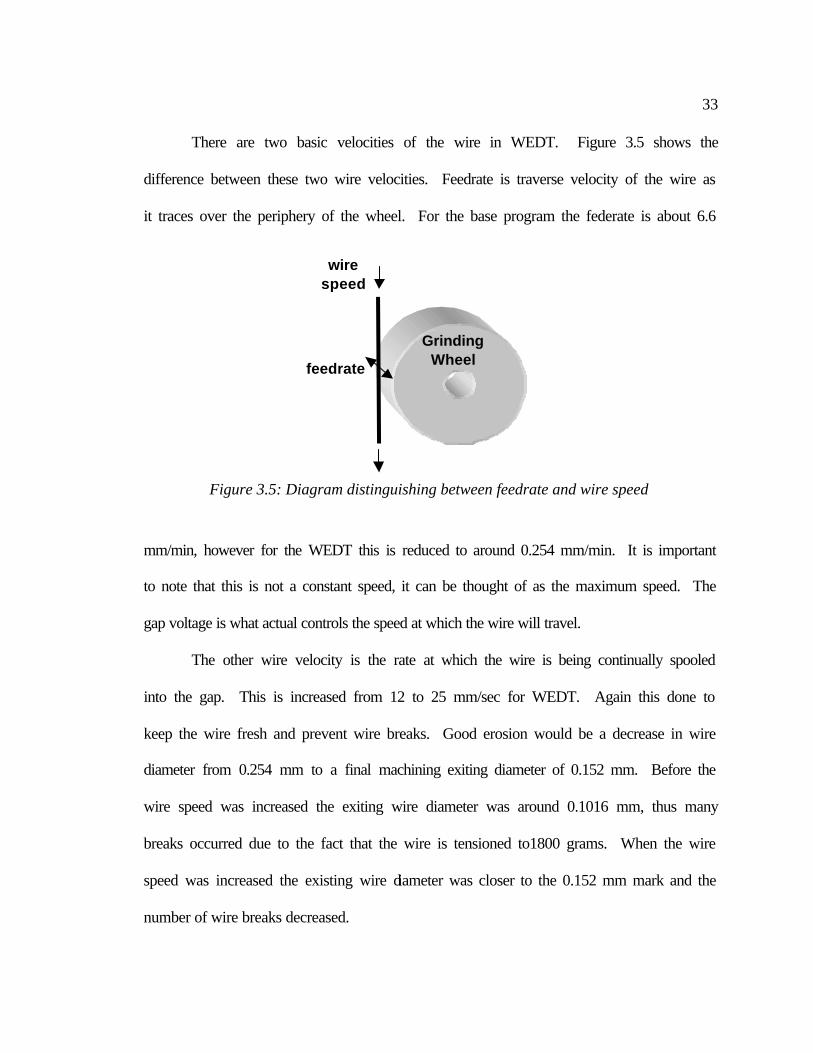
There are two basic velocities of the wire in WEDT. Figure 3.5 shows the
difference between these two wire velocities. Feedrate is traverse velocity of the wire as
it traces over the periphery of the wheel. For the base program the federate is about 6.6
mm/min, however for the WEDT this is reduced to around 0.254 mm/min. It is important
to note that this is not a constant speed, it can be thought of as the maximum speed. The
gap voltage is what actual controls the speed at which the wire will travel.
The other wire velocity is the rate at which the wire is being continually spooled
into the gap. This is increased from 12 to 25 mm/sec for WEDT. Again this done to
keep the wire fresh and prevent wire breaks. Good erosion would be a decrease in wire
diameter from 0.254 mm to a final machining exiting diameter of 0.152 mm. Before the
wire speed was increased the exiting wire diameter was around 0.1016 mm, thus many
breaks occurred due to the fact that the wire is tensioned to1800 grams. When the wire
speed was increased the existing wire diameter was closer to the 0.152 mm mark and the
number of wire breaks decreased.
feedrate
Grinding Wheel
wire speed
Figure 3.5: Diagram distinguishing between feedrate and wire speed
34
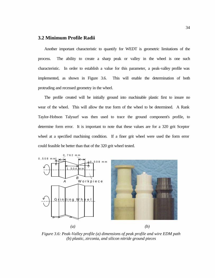
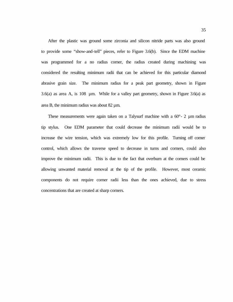
3.2 Minimum Profile Radii
Another important characteristic to quantify for WEDT is geometric limitations of the
process. The ability to create a sharp peak or valley in the wheel is one such
characteristic. In order to establish a value for this parameter, a peak-valley profile was
implemented, as shown in Figure 3.6. This will enable the determination of both
protruding and recessed geometry in the wheel.
The profile created will be initially ground into machinable plastic first to insure no
wear of the wheel. This will allow the true form of the wheel to be determined. A Rank
Taylor-Hobson Talysurf was then used to trace the ground component's profile, to
determine form error. It is important to note that these values are for a 320 grit Sceptor
wheel at a specified machining condition. If a finer grit wheel were used the form error
could feasible be better than that of the 320 grit wheel tested.
(a) (b)
Figure 3.6: Peak-Valley profile (a) dimensions of peak profile and wire EDM path (b) plastic, zirconia, and silicon nitride ground pieces
G r i n d i n g W h e e l
0 . 5 0 8 m m0 . 7 6 2 m m
W o r k p i e c e
1 . 5 0 4 m m
0 . 5 0 8 m m
AB
35
After the plastic was ground some zirconia and silicon nitride parts was also ground
to provide some “show-and-tell” pieces, refer to Figure 3.6(b). Since the EDM machine
was programmed for a no radius corner, the radius created during machining was
considered the resulting minimum radii that can be achieved for this particular diamond
abrasive grain size. The minimum radius for a peak part geometry, shown in Figure
3.6(a) as area A, is 108 µm. While for a valley part geometry, shown in Figure 3.6(a) as
area B, the minimum radius was about 82 µm.
These measurements were again taken on a Talysurf machine with a 60°- 2 µm radius
tip stylus. One EDM parameter that could decrease the minimum radii would be to
increase the wire tension, which was extremely low for this profile. Turning off comer
control, which allows the traverse speed to decrease in turns and corners, could also
improve the minimum radii. This is due to the fact that overburn at the corners could be
allowing unwanted material removal at the tip of the profile. However, most ceramic
components do not require corner radii less than the ones achieved, due to stress
concentrations that are created at sharp corners.
36
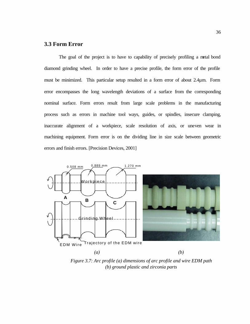
3.3 Form Error
The goal of the project is to have to capability of precisely profiling a metal bond
diamond grinding wheel. In order to have a precise profile, the form error of the profile
must be minimized. This particular setup resulted in a form error of about 2.4µm. Form
error encompasses the long wavelength deviations of a surface from the corresponding
nominal surface. Form errors result from large scale problems in the manufacturing
process such as errors in machine tool ways, guides, or spindles, insecure clamping,
inaccurate alignment of a workpiece, scale resolution of axis, or uneven wear in
machining equipment. Form error is on the dividing line in size scale between geometric
errors and finish errors. [Precision Devices, 2001]
(a) (b)
Figure 3.7: Arc profile (a) dimensions of arc profile and wire EDM path (b) ground plastic and zirconia parts
G r i n d i n g W h e e l
EDM Wi re Tra jec tory o f the EDM wi re
W o r k p i e c e
0.508 mm 0.889 mm 1.270 mm
A
B
C
37
Figure 3.7 shows the arc profile that was used to determine form error capabilities
of the EDM truing process. With this profile the machine will have to make steps in both
the x- and y- directions. An arc is the standard shaped used in the determination of form
error. Note that this is dependent on the EDM’s machine quality and the performance of
the spindle along with other factors. Thus if any of these parameters are changed, these
tolerances will not be the same. The forming of the wheel was performed in a single pass
that removed the bulk of the material. An additional cleanup pass, using the same
machine path, was required to ensure complete spark out.
After the profile was burned into the wheel, the first pieces were machined. A
Centerless Deadtrue grinder at Cummins Technical Center (CTC) was used to grind a
piece of machinable plastic. The plastic allows machining with no wheel wear, thus
revealing the true form of the wheel. Then by using a Taylor Hobson Form Talysurf with
1 mm ball stylus, the form error was determined.
As mentioned previously form error is a dividing line between finish and
geometric errors, i.e. difference between surface roughness and surface waviness. The
software that analyzes form error data from the Talysurf first has to establish a base from
which to measure error. By using the circle fit feature in the software an average radius
“perfect circle” is created on which to compare the data. Form error is then defined as
the peak-to-valley deviation from this circle, which has the mean radius of all data points
taken.
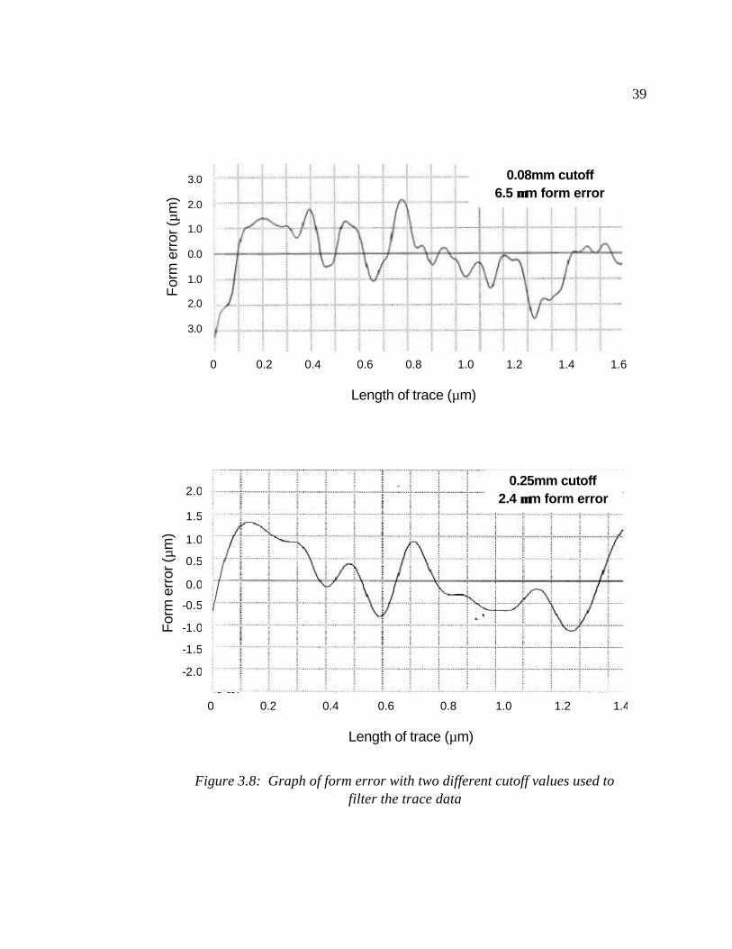
The arc was measured and analyzed with both a .08mm and .25mm cutoff, to give
a form error of 6.5 µm and 2.4 µm, respectively. The cutoff is defined as the threshold of
38
wavelength for which will be keep for analyze, all waves with wavelengths shorter than
that are removed from the data. The smaller the cutoff wavelength then the more surface
roughness will skew the form error results. But, if to large a cutoff is used some of the
form error may be lost. There is a fine line in determining this cutoff length; the standard
in metrology is 0.25mm. Figure 3.8 shows the results from the form Talysurf software.
One additional note is that the mean arc radius is removed from the data, thus the
deviation is measured from the x-axis on the graph. Also note that this is a peak-to-
valley deviation of the form error. In other words, all the data points can be contained
within two concentric circles whose radii differ by the amount of the form error.
39
Figure 3.9: Form error for 0.08mm and 0.25mm cutoff
2.0
1.5
1.0
0.5
0.0
-0.5
-1.0
-1.5
-2.0
0.25mm cutoff 2.4 µµm form error
For
m e
rror
(µm
)
0 0.2 0.4 0.6 0.8 1.0 1.2 1.4
Length of trace (µm)
3.0
2.0
1.0
0.0
1.0
2.0
3.0
0.08mm cutoff 6.5 µµm form error
For
m e
rror
(µm
)
0 0.2 0.4 0.6 0.8 1.0 1.2 1.4 1.6
Length of trace (µm)
Figure 3.8: Graph of form error with two different cutoff values used to filter the trace data
40
4 GRINDING STUDY
After WEDT proved feasible to create a precise formed wheel, a study was
implemented to examine the wheel’s grinding characteristics. The results of a single
point diamond wheel were used for comparing the results from the EDM trued wheel.
The questions to be answered by the test include:
• Which of the truing methods created a wheel that performed grinding operation most effectively?
• How does surface finish of the ground component compare between truing
method?
• How does wheel wear rates compare between the truing methods?
The test consisted of comparing two truing methods for a metal bond diamond grinding
wheel. One of the wheels was trued using a single point diamond, while the WEDT
process presented in this report trued the other wheel. Because the EDM process
performed both truing and dressing simultaneously, the EDM wheels required no
additional preparation. The single point trued wheel was dressed with a silicon carbide
stick to create chip clearance. The following sections in Chapter 4 will cover the setup of
the test and present the results of this study.
41
4.1 Setup of Grinding Study
As mentioned previously there will be two truing methods compared in this study,
thus two truing procedures. The following sections will discuss how the wheels were
prepared and also the grinding setup and procedures.
4.1.1 Wheel Preparation
A single point diamond trued wheel was used to compare against the EDM trued
wheels. The diamond was feed at 5 µm/pass, and then traversed over the wheel surface
at 127 mm/min. The wheel’s surface speed during truing was 20 m/s. After the wheel
was trued it was then dressed using a 220 grit silicon carbide stick. The stick was fed
into the wheel by hand until nearly 25 mm of the stick had been consumed. This will
remove some of the metal matrix from around the diamond for chip clearance.
WEDT method presented in this report was used to create a wire trued wheel.
With WEDT the truing and dressing was performed simultaneously, thus no stick
dressing is required. The WEDT process parameters included a gap voltage of 70 V,
spark cycle of 32 µm, on-time of 12 µm, feedrate of 0.254 mm/min, wire speed of 25
mm/sec, and wire tension was 1800 grams
4.1.2 Grinding Procedure
A 320 grit metal bond wheel, Norton’s Scepter, was used as the grinding wheel
for this study. This wheel has proven, through a study at Oak Ridge National Lab, to
provide excellent grinding of a wide range of ceramics. Silicon nitride sample tiles from
Toshiba (TSN-10) are used as the workpiece. The samples are 42.5 mm long and have a
42
width of 6.35 mm. The width of the wheel 12.7 mm, enabling wheel wear data to be
collected. The tiles were aligned to the middle of the wheel leaving ungrounded, virgin
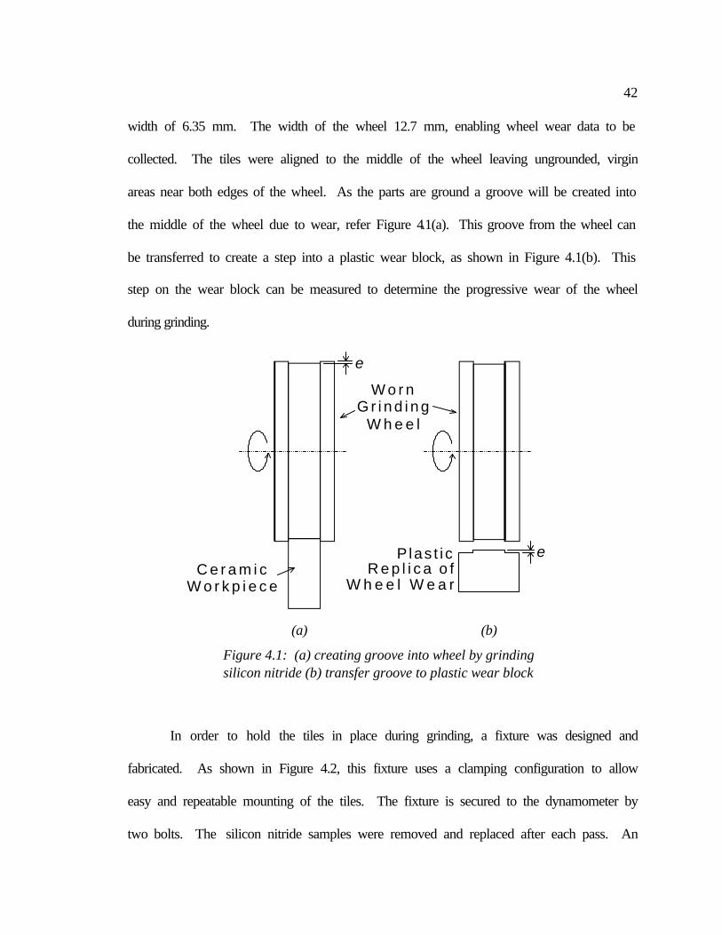
areas near both edges of the wheel. As the parts are ground a groove will be created into
the middle of the wheel due to wear, refer Figure 4.1(a). This groove from the wheel can
be transferred to create a step into a plastic wear block, as shown in Figure 4.1(b). This
step on the wear block can be measured to determine the progressive wear of the wheel
during grinding.
In order to hold the tiles in place during grinding, a fixture was designed and
fabricated. As shown in Figure 4.2, this fixture uses a clamping configuration to allow
easy and repeatable mounting of the tiles. The fixture is secured to the dynamometer by
two bolts. The silicon nitride samples were removed and replaced after each pass. An
C e r a m i cW o r k p i e c e
e
e
Plas t i cR e p l i c a o f
W h e e l W e a r
W o r nG r i n d i n g
W h e e l
(a) (b)
Figure 4.1: (a) creating groove into wheel by grinding silicon nitride (b) transfer groove to plastic wear block
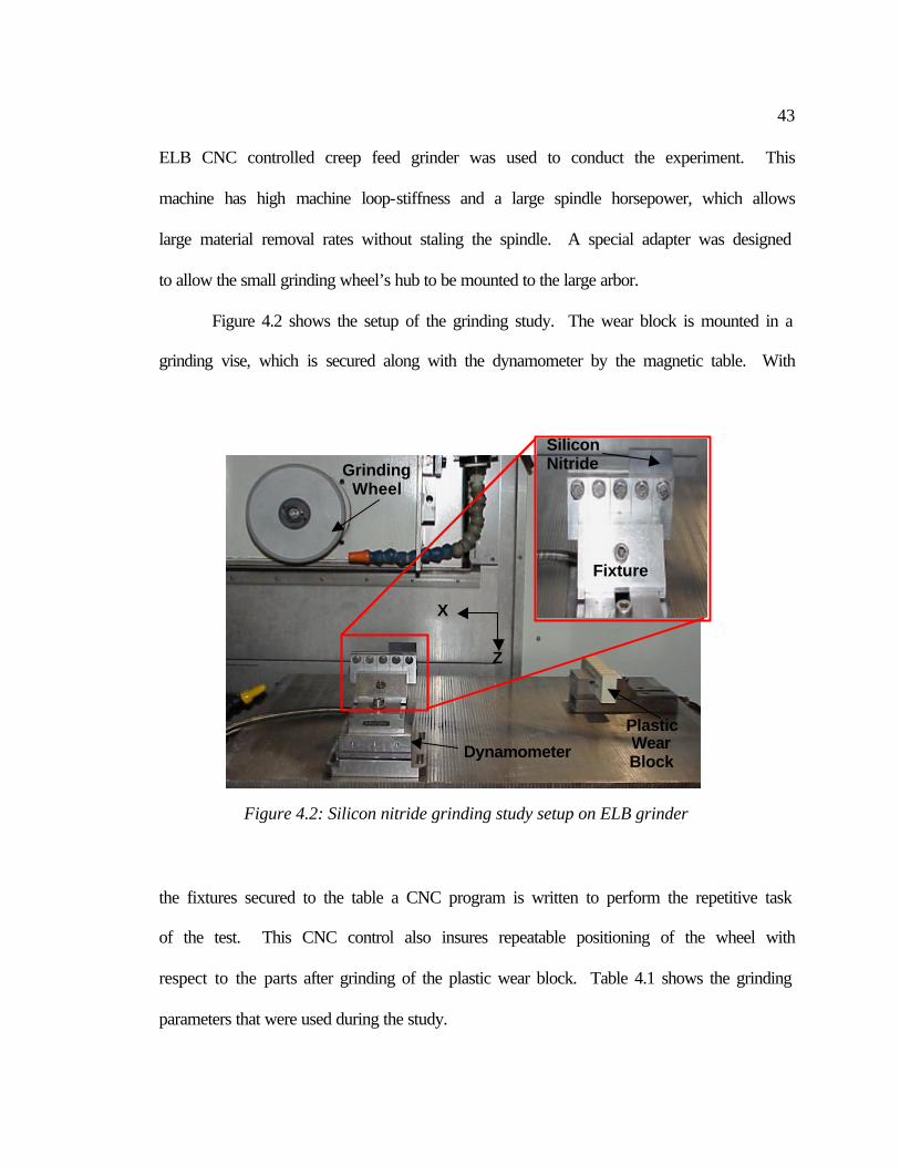
43
ELB CNC controlled creep feed grinder was used to conduct the experiment. This
machine has high machine loop-stiffness and a large spindle horsepower, which allows
large material removal rates without staling the spindle. A special adapter was designed
to allow the small grinding wheel’s hub to be mounted to the large arbor.
Figure 4.2 shows the setup of the grinding study. The wear block is mounted in a
grinding vise, which is secured along with the dynamometer by the magnetic table. With
the fixtures secured to the table a CNC program is written to perform the repetitive task
of the test. This CNC control also insures repeatable positioning of the wheel with
respect to the parts after grinding of the plastic wear block. Table 4.1 shows the grinding
parameters that were used during the study.
Grinding Wheel
Plastic Wear Block
Dynamometer
Figure 4.2: Silicon nitride grinding study setup on ELB grinder
Fixture
Silicon Nitride
Z
X
44
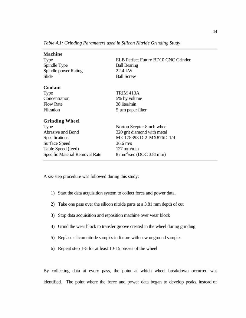
Table 4.1: Grinding Parameters used in Silicon Nitride Grinding Study
Machine Type ELB Perfect Future BD10 CNC Grinder Spindle Type Ball Bearing Spindle power Rating 22.4 kW Slide Ball Screw Coolant Type TRIM 413A Concentration 5% by volume Flow Rate 38 liter/min Filtration 5 µm paper filter Grinding Wheel Type Norton Scepter 8inch wheel Abrasive and Bond 320 grit diamond with metal Specifications ME 178393 D-2-MX876D-1/4 Surface Speed 36.6 m/s Table Speed (feed) 127 mm/min Specific Material Removal Rate 8 mm2/sec (DOC 3.81mm)
A six-step procedure was followed during this study:
1) Start the data acquisition system to collect force and power data.
2) Take one pass over the silicon nitride parts at a 3.81 mm depth of cut
3) Stop data acquisition and reposition machine over wear block
4) Grind the wear block to transfer groove created in the wheel during grinding
5) Replace silicon nitride samples in fixture with new unground samples
6) Repeat step 1-5 for at least 10-15 passes of the wheel
By collecting data at every pass, the point at which wheel breakdown occurred was
identified. The point where the force and power data began to develop peaks, instead of
45
smooth transitioning line, was defined as the breakdown point. Also by replacing the
samples after every pass with new ones, a graph of surface finish as a function of material
removed was constructed. In the following sections, these grinding trends are discussed
and some theory is developed to describe the trends.
4.2 Grinding Forces
The load on the spindle was measured during grinding in order to determine the
most effective truing method. If the wheel is “open”, the spindle load will be low. If the
wheel is not open, i.e. no chip clearance, then the diamonds are not exposed properly and
spindle load will be high. The next two sections discuss the instrumentation used to
gather the data and the results from the study.
4.2.1 Instrumentation to Collect Force and Power Data
In order to measure this spindle power, a Hall-effect power sensor was installed
on the ELB machine. Since power is the product of voltage and current, the load monitor
measures the current and voltage from the three-phase spindle power supply. Then a DC
voltage output signal is given relative to the spindle load, which is then converted to
power by a calibration constant. The output signal was passed through a low-pass RC
filter to remove unwanted noise from the signal. The cutoff frequency is determined by
equation 4.1, where R is the resistance and C is the capacitance.
46
CRð21
f cutoff ⋅⋅= (4.1)
With R set at 36Ω and C selected at 10µF the cutoff frequency, fcutoff, is 442 Hz. This
value is well above the 60 Hz of grinding frequency.
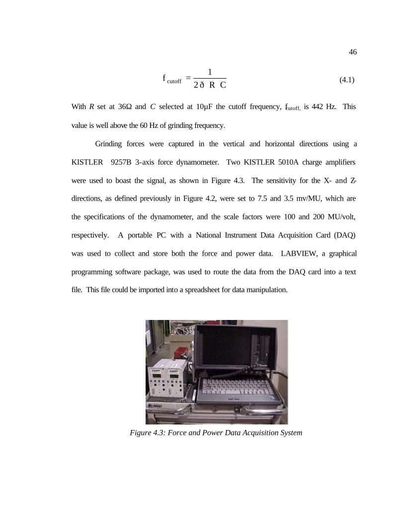
Grinding forces were captured in the vertical and horizontal directions using a
KISTLER 9257B 3-axis force dynamometer. Two KISTLER 5010A charge amplifiers
were used to boast the signal, as shown in Figure 4.3. The sensitivity for the X- and Z-
directions, as defined previously in Figure 4.2, were set to 7.5 and 3.5 mv/MU, which are
the specifications of the dynamometer, and the scale factors were 100 and 200 MU/volt,
respectively. A portable PC with a National Instrument Data Acquisition Card (DAQ)
was used to collect and store both the force and power data. LABVIEW, a graphical
programming software package, was used to route the data from the DAQ card into a text
file. This file could be imported into a spreadsheet for data manipulation.
Figure 4.3: Force and Power Data Acquisition System
47
4.2.2 Force Results
In grinding, forces are generated due to friction between the wheel and workpiece.
This is required in order for the abrasive grains to remove the work material. However,
for a given depth of cut and grinding conditions, these forces should be minimized to
reduce wheel wear. One factor that affects the magnitude of the grinding force is how
well the wheel has been dressed.
Dressing refers to the removal of the metal matrix that surrounds the diamond
abrasive. If done properly the diamond should be protruding from the metal matrix
surface, creating chip clearance. Thus, as the abrasive grain plows through the
workpiece, the removed material has an area to be accepted. Then, as that area rotates
out of the grinding zone the chips are discharged from the wheel. If the space around the
abrasive is not present, there is no room for the chips to go, which creates high grinding
forces. Also if the diamonds are not protruding far enough, then the metal matrix begins
to rub the workpiece surface excessively, creating higher frictional forces.
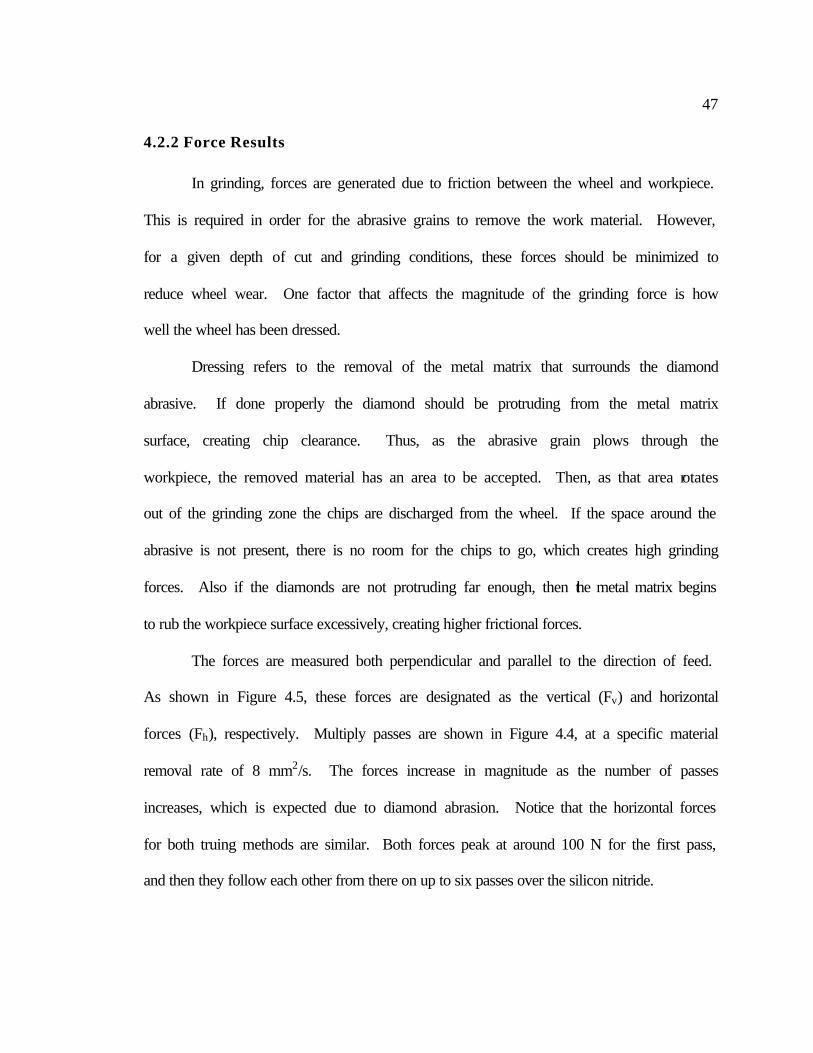
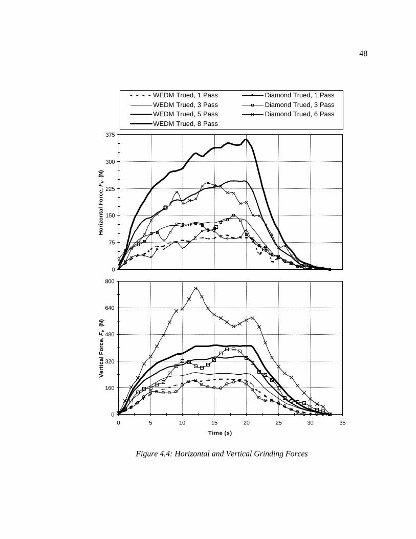
The forces are measured both perpendicular and parallel to the direction of feed.
As shown in Figure 4.5, these forces are designated as the vertical (Fv) and horizontal
forces (Fh), respectively. Multiply passes are shown in Figure 4.4, at a specific material
removal rate of 8 mm2/s. The forces increase in magnitude as the number of passes
increases, which is expected due to diamond abrasion. Notice that the horizontal forces
for both truing methods are similar. Both forces peak at around 100 N for the first pass,
and then they follow each other from there on up to six passes over the silicon nitride.
48
Figure 4.4: Horizontal and Vertical Grinding Forces
0
75
150
225
300
375
Ho
rizo
nta
l Fo
rce,
FH
(N
)WEDM Trued, 1 Pass Diamond Trued, 1 Pass
WEDM Trued, 3 Pass Diamond Trued, 3 PassWEDM Trued, 5 Pass Diamond Trued, 6 Pass
WEDM Trued, 8 Pass
0
160
320
480
640
800
0 5 10 15 20 25 30 35
Time (s)
Ver
tica
l Fo
rce,
FV
(N
)
49
However, the vertical forces do not follow the same pattern. Initially on the first
pass, both wheels create the same level of forces. The single point diamond trued wheel
started to have high force peaks, while the EDM trued wheel had smooth force lines. The
force level for the third pass using the traditionally trued wheel was up on the level of the
EDM trued wheel after eight passes at around 400 N. The sixth pass with the
traditionally dressed wheel reached forces in excess of 700 N. This indicates that the
single point diamond trued wheel broke down earlier than the EDM trued wheel.
Under normal surface grinding conditions, i.e. light depths of cut, the force are
measured in the vertical and horizontal directions directly are the normal and tangential
forces. However, with a creep feed grinding configuration like the one in this
experiment, no longer can the horizontal and vertical forces be considered as the normal
and tangential forces, due to the large arc of machining. Figure 4.5 shows that the normal
and tangential forces begin to slide up the machining arc as the depth of cut (t) increases.
Grinding Wheel
Fh
Ft
Fn
Fv
t
Figure 4.5: Diagram of grinding forces
Ceramic Workpiece
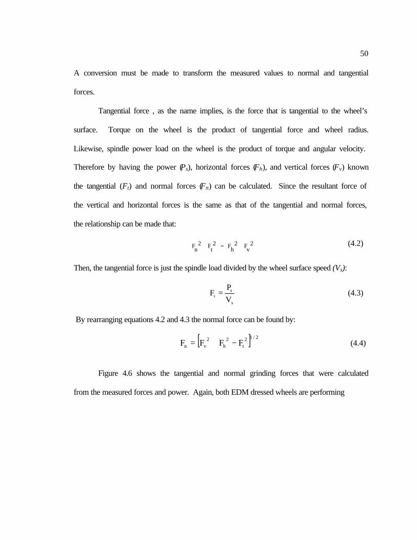
50
A conversion must be made to transform the measured values to normal and tangential
forces.
Tangential force , as the name implies, is the force that is tangential to the wheel’s
surface. Torque on the wheel is the product of tangential force and wheel radius.
Likewise, spindle power load on the wheel is the product of torque and angular velocity.
Therefore by having the power (Ps), horizontal forces (Fh), and vertical forces (Fv) known
the tangential (Ft) and normal forces (Fn) can be calculated. Since the resultant force of
the vertical and horizontal forces is the same as that of the tangential and normal forces,
the relationship can be made that:
+=
+ 2
vF2hF2
tF2nF (4.2)
Then, the tangential force is just the spindle load divided by the wheel surface speed (Vs):
s
st V
PF = (4.3)
By rearranging equations 4.2 and 4.3 the normal force can be found by:
[ ] 2/12t
2h
2vn FFFF −+= (4.4)
Figure 4.6 shows the tangential and normal grinding forces that were calculated
from the measured forces and power. Again, both EDM dressed wheels are performing
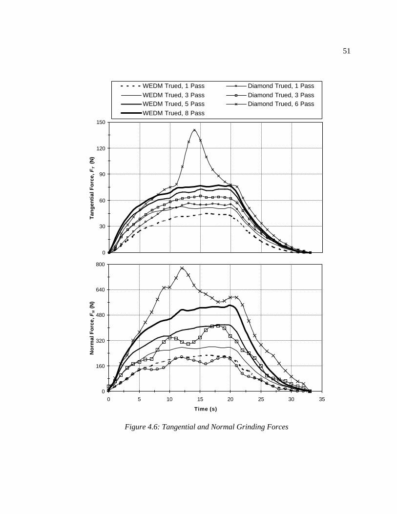
51
Figure 4.6: Tangential and Normal Grinding Forces
0
30
60
90
120
150
Tan
gen
tial
Fo
rce,
FT
(N
)WEDM Trued, 1 Pass Diamond Trued, 1 Pass
WEDM Trued, 3 Pass Diamond Trued, 3 PassWEDM Trued, 5 Pass Diamond Trued, 6 Pass
WEDM Trued, 8 Pass
0
160
320
480
640
800
0 5 10 15 20 25 30 35
Time (s)
No
rmal
Fo
rce,
FN (N
)
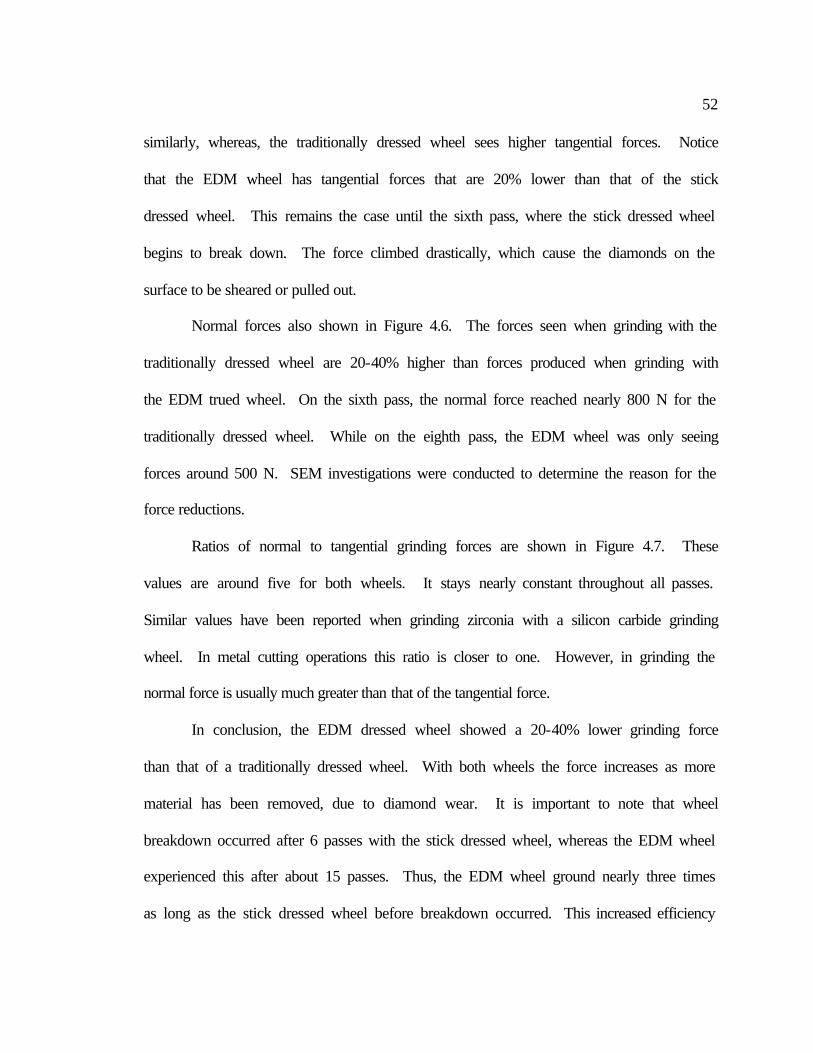
52
similarly, whereas, the traditionally dressed wheel sees higher tangential forces. Notice
that the EDM wheel has tangential forces that are 20% lower than that of the stick
dressed wheel. This remains the case until the sixth pass, where the stick dressed wheel
begins to break down. The force climbed drastically, which cause the diamonds on the
surface to be sheared or pulled out.
Normal forces also shown in Figure 4.6. The forces seen when grinding with the
traditionally dressed wheel are 20-40% higher than forces produced when grinding with
the EDM trued wheel. On the sixth pass, the normal force reached nearly 800 N for the
traditionally dressed wheel. While on the eighth pass, the EDM wheel was only seeing
forces around 500 N. SEM investigations were conducted to determine the reason for the
force reductions.
Ratios of normal to tangential grinding forces are shown in Figure 4.7. These
values are around five for both wheels. It stays nearly constant throughout all passes.
Similar values have been reported when grinding zirconia with a silicon carbide grinding
wheel. In metal cutting operations this ratio is closer to one. However, in grinding the
normal force is usually much greater than that of the tangential force.
In conclusion, the EDM dressed wheel showed a 20-40% lower grinding force
than that of a traditionally dressed wheel. With both wheels the force increases as more
material has been removed, due to diamond wear. It is important to note that wheel
breakdown occurred after 6 passes with the stick dressed wheel, whereas the EDM wheel
experienced this after about 15 passes. Thus, the EDM wheel ground nearly three times
as long as the stick dressed wheel before breakdown occurred. This increased efficiency
53
was theorized to be caused by the manner in which the EDM sparks dress the wheel.
However, further SEM investigations of the wheels’ surface will be used to study this
theory.
Figure 4.7: Ratio of Tangential to Normal Grinding Forces
0
2
4
6
8
10
5 10 15 20 25
Time (s)
FN/F
T R
atio
WEDM Trued, 1 Pass Diamond Trued, 1 PassWEDM Trued, 3 Pass Diamond Trued, 3 PassWEDM Trued, 5 Pass Diamond Trued, 6 PassWEDM Trued, 8 Pass
54
4.3 Surface Roughness of Ground Silicon Nitride
Surface roughness is an important factor to ground components. Usually, there is
a specified tolerance that must be met in order for the ground component to function
properly. The driving factors for surface finish include abrasive size, grinding
parameters, and dressing characteristics. For this study, both the abrasive size and
grinding parameters were held constant in order to revel the effects of dressing.
A Talysurf from Rank-Taylor Hobson was used to measure the surface roughness.
The stylus used was a standard 2011, which has 2 µm radius diamond tip. A 0.25 mm
cutoff was selected to filter out low frequency signals (waviness). This is the standard
cutoff wavelength for this radius stylus tip [Precision Devices, 2001]. Three
measurements were taken per piece and the results were averaged. The direction of the
trace was taken perpendicular to the feed, which should produce the maximum
roughness. Both peak-to-valley roughness (Rz) and average roughness (Ra) results are
presented.
Figure 4.8 shows the roughness values obtained from the experiment. The results
show that the EDM trued wheel create slightly, less than 0.05 µm, rougher parts. The
peak-to-valley results are much closer for all three wheels. Both wheels produce better
surface finish as the number of ground parts increases, as shown by the downward trend
of the roughness graphs. This can be attributed to a reduction in diamond height and also
an increase in the wear flat on the diamond.
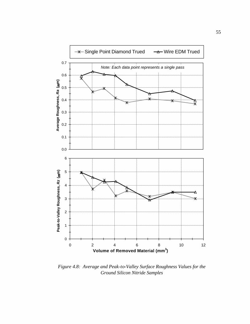
55
Figure 4.8: Average and Peak-to-Valley Surface Roughness Values for the Ground Silicon Nitride Samples
0.0
0.1
0.2
0.3
0.4
0.5
0.6
0.7
Ave
rag
e R
ou
gh
nes
s, R
a ( µµ
m)
Single Point Diamond Trued Wire EDM Trued
Note: Each data point represents a single pass
0
1
2
3
4
5
6
0 2 4 6 8 10 12
Volume of Removed Material (mm3)
Pea
k-to
-Val
ley
Ro
ug
hn
ess,
Rz
( µµm
)
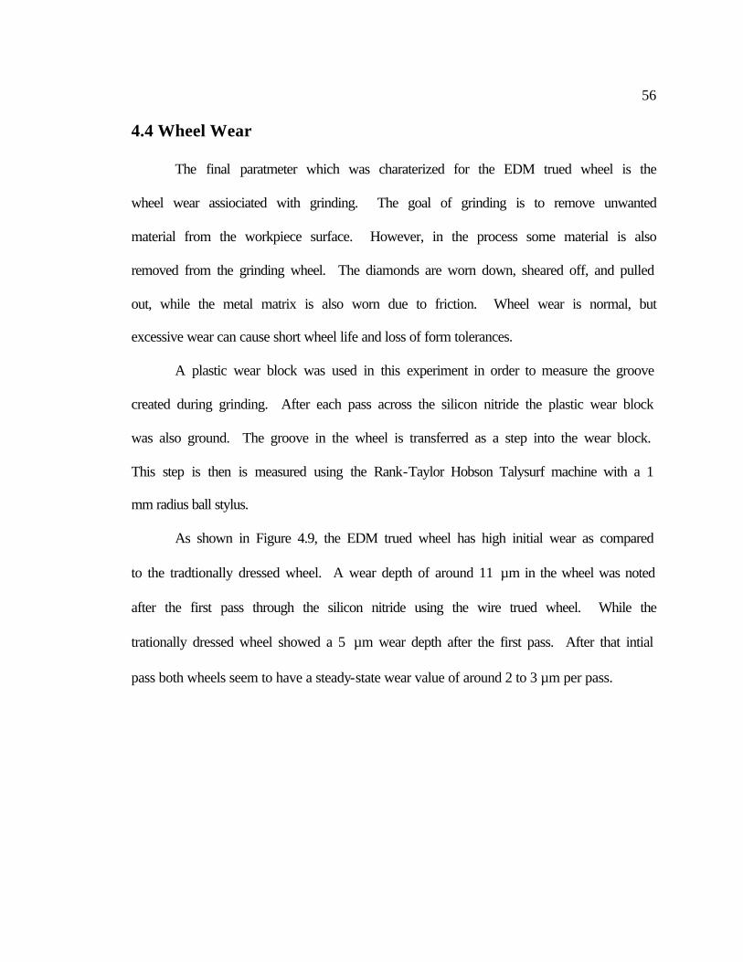
56
4.4 Wheel Wear
The final paratmeter which was charaterized for the EDM trued wheel is the
wheel wear assiociated with grinding. The goal of grinding is to remove unwanted
material from the workpiece surface. However, in the process some material is also
removed from the grinding wheel. The diamonds are worn down, sheared off, and pulled
out, while the metal matrix is also worn due to friction. Wheel wear is normal, but
excessive wear can cause short wheel life and loss of form tolerances.
A plastic wear block was used in this experiment in order to measure the groove
created during grinding. After each pass across the silicon nitride the plastic wear block
was also ground. The groove in the wheel is transferred as a step into the wear block.
This step is then is measured using the Rank-Taylor Hobson Talysurf machine with a 1
mm radius ball stylus.
As shown in Figure 4.9, the EDM trued wheel has high initial wear as compared
to the tradtionally dressed wheel. A wear depth of around 11 µm in the wheel was noted
after the first pass through the silicon nitride using the wire trued wheel. While the
trationally dressed wheel showed a 5 µm wear depth after the first pass. After that intial
pass both wheels seem to have a steady-state wear value of around 2 to 3 µm per pass.
57
Figure 4.9: Incremental and Actual Wheel Wear Depth
0
2
4
6
8
10
12In
crem
enta
l Wea
r D
epth
( µµm
)
Single Point Diamond Trued Wire EDM Trued
Note: Each data point represents a single pass
0
5
10
15
20
25
30
0 2 4 6 8 10 12
Volume of Removed Material (mm3)
Act
ual
Wea
r D
epth
( µµm
)
58
What is believed to occur is shearing off of over-protruding diamonds in the EDM
trued wheels. With tradtional mechanical truing the diamonds and metal matrix are at the
same height, then a dressing stick is used to erode the matrix, causing the diamonds to
protrude. However, with EDM dressing the diamonds do not come in contact with a
large mechanical force during truing. The electrical spark erodes the metal matrix,
causing it to be at a constant height. Yet the diamonds are left a varies heights from the
metal surface. Further SEM studies will be needed to verify this theory.
4.5 Summary of Grinding Study
A 20-40% reduction in force was noted when using the EDM trued wheel as
compared to the single point trued, stick dressed wheel. Wheel breakdown occurred after
6 ground parts using the stick dressed wheel. It took about 15 passes before the EDM
trued wheel to began to breakdown. SEM should give some insight on why the EDM
wheel performed more effectively than the stick dressed wheel.
Surface finish on the ground parts were all very similar. The EDM wheel
produced a average surface finish that was about 0.05 µm rougher than the stick dressed
wheel. Both of the wheels produced parts with an average surface roughness below 1
µm. The peak-to-valley values were similar for both wheels at around 3-5 µm.
Roughness of the ground parts decreased as the number of passes increased, as expected,
due to smoothing and wear of the diamond abrasive.
The wear of the EDM trued wheel created the most concern. After only one pass
the wear wear depth was measured to be around 11 µm for the wire trued wheel. This
59
was nearly double the wear of the stick dressed wheel. However, it is believed that this
wear is acutally the shearing off of over-protruding diamonds. Since only a small force
occurs during truing, the diamonds could be over protruding. Thus, in the presence of the
mechanical forces of grinding these diamonds are sheared off to diserable height. One
note to remember is that the metal matrix holds the wheel form, thus diamond shearing
will not affect form tolerance.
60
5 SCANNING ELECTRON MICROSCOPE (SEM) INVESTIGATION
The first SEM used to examine the surface of a solid specimen was described by
Zworykin et al. in 1942, working in the RCA Laboratories in the United States. The
electron optics of the instrument consisted of three electrostatic lenses with scan coils
placed between the second and third lenses [Breton, 2001]. The electron gun was located
at the bottom so the specimen chamber was at a comfortable height for the operator
[Breton, 2001]. Since then, the electron microscope has become a premier tool when
investigating microscopic features. Unlike the optical microscope, which uses a beam of
light to reflect off the surface, SEM uses a beam of electrons that are both absorbed and
reflected by the surface. The advantage of SEM includes both a high level of
magnification and a large depth of field.
As mentioned previously one concern, which arose during the grinding study
using the WEDT wheels, was the high initial wheel wear. A theory was developed that
the diamonds on the WEDT wheel surface are over-protruding and are sheared off or
pulled out by the mechanical forces of grinding. To investigate this theory, SEM was
used to examine the wheel’s surface. In order to determine the height of the diamonds,
the Alicona stereo-SEM imaging software was used.
The first two sections of this chapter present the SEM investigation of a WEDT
wheel that was used to grind silicon nitride. The third section examines the surface of a
traditional stick dressed wheel. Some debris from the WEDT process is shown in section
four, followed by a review of this chapter in the final section.
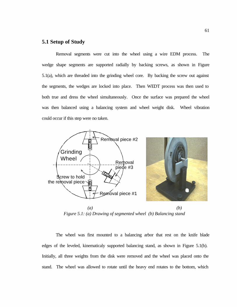
61
5.1 Setup of Study
Removal segments were cut into the wheel using a wire EDM process. The
wedge shape segments are supported radially by backing screws, as shown in Figure
5.1(a), which are threaded into the grinding wheel core. By backing the screw out against
the segments, the wedges are locked into place. Then WEDT process was then used to
both true and dress the wheel simultaneously. Once the surface was prepared the wheel
was then balanced using a balancing system and wheel weight disk. Wheel vibration
could occur if this step were no taken.
The wheel was first mounted to a balancing arbor that rest on the knife blade
edges of the leveled, kinematicaly supported balancing stand, as shown in Figure 5.1(b).
Initially, all three weights from the disk were removed and the wheel was placed onto the
stand. The wheel was allowed to rotate until the heavy end rotates to the bottom, which
(a) (b) Figure 5.1: (a) Drawing of segmented wheel (b) Balancing stand
Removal piece #1
GrindingWheel
Removal piece #2
Removal piece #3
Screw to holdthe removal piece
62
is then marked. One of the weights was placed at the heavy spot, while the other two
were equally spaced away from the heavy spot. These two weights were then moved
equally further away until the heavy spot changes. If the wheel was too far out of balance
then a drill spot must be placed in the grinding wheel near the heavy spot to remove some
of the weight. Once the wheel is balanced, it will roll from one end of the stand to the
other without changing direction. This process is time consuming, but it assures the
balance of the wheel.
Once the wheel was prepared it was time to grind the silicon nitride. The same
silicon nitride tiles were used as in the previous test. However, this time they were not
stacked two wide, thus a new holder was cut using wire EDM. Since the pieces are only
3.175 mm wide and the wheel is 12.7 mm wide, two depths of cut and a virgin surface
could be examined. This research was conducted at Oak Ridge National Lab at the High
Temperature Materials Laboratory. A Harig 618 CNC controlled surface grinder, Figure
5.2(a), was used to perform the specimen grinding preparation. Table speed was set at
3.048 m/min and wheel surface speed was set at 37 m/s.
The two total grinding depths used were 0.127 and 12.7 mm. These total depths
of cuts were reached using a 0.127 mm increment of downfeed per-pass. The single pass
gave data for light grinding, while the 100 passes gave data for heavy, steady state
grinding. Once the grinding was completed, the specimen was removed from the wheel
for SEM inspection. Visually, there was a difference between the virgin surface of the
wheel and the areas that had been used for grinding. The grinding areas of the wheel
appeared shiny due to the smearing of the metal matrix during grinding.
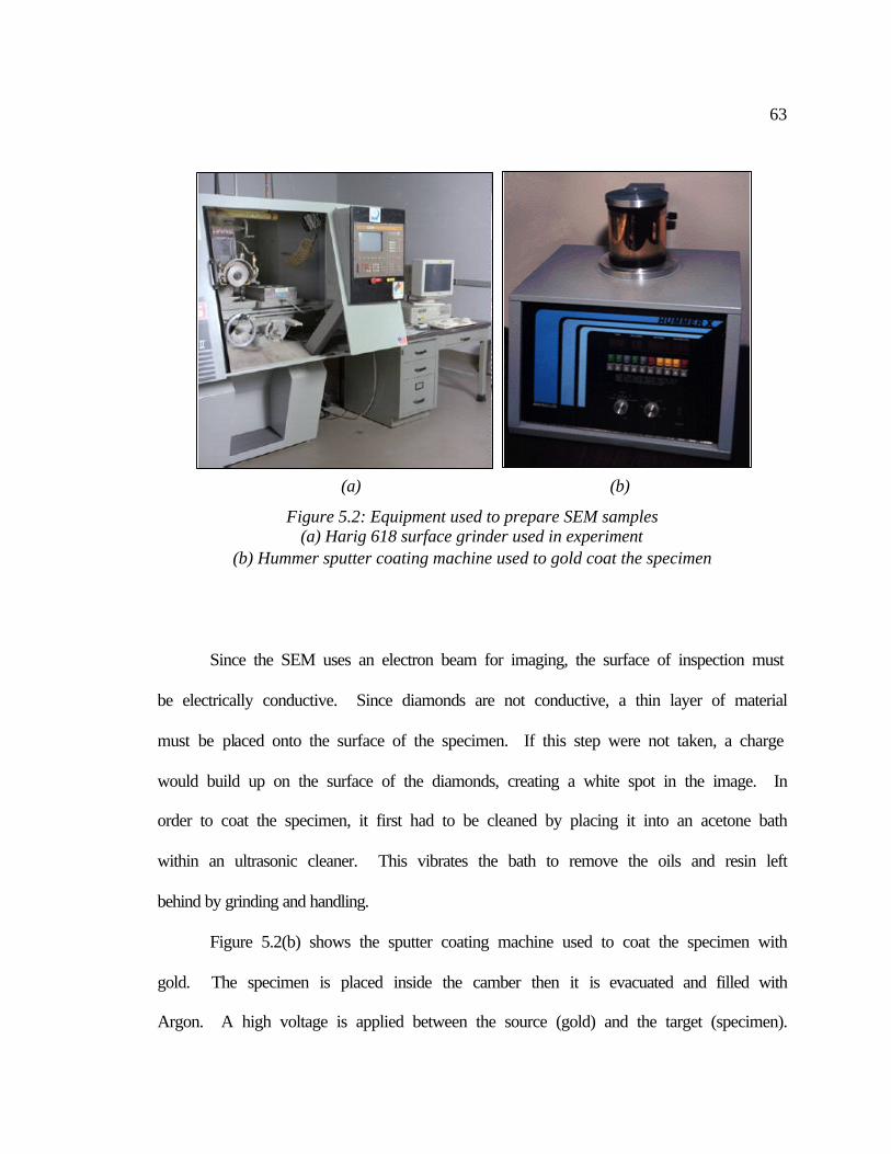
63
Since the SEM uses an electron beam for imaging, the surface of inspection must
be electrically conductive. Since diamonds are not conductive, a thin layer of material
must be placed onto the surface of the specimen. If this step were not taken, a charge
would build up on the surface of the diamonds, creating a white spot in the image. In
order to coat the specimen, it first had to be cleaned by placing it into an acetone bath
within an ultrasonic cleaner. This vibrates the bath to remove the oils and resin left
behind by grinding and handling.
Figure 5.2(b) shows the sputter coating machine used to coat the specimen with
gold. The specimen is placed inside the camber then it is evacuated and filled with
Argon. A high voltage is applied between the source (gold) and the target (specimen).
(a) (b)
Figure 5.2: Equipment used to prepare SEM samples (a) Harig 618 surface grinder used in experiment
(b) Hummer sputter coating machine used to gold coat the specimen
64
The excited electrons then bounce off the source onto the target discharging small gold
particles from the gold source, which then adhere to the surface of the specimen. This
coating is very thin and uniform. Once the specimen was cleaned and coated, it was
ready to be viewed under SEM.
5.2 SEM Results of WEDT Wheel Surface
The SEM used was a Hiatchi S-4700 field emission scanning electron
microscope. This was selected due to the automated stage positioning and tilting
features, which is required for constructing a 3-D image of the surface. Stereo-SEM can
quantify the height of features from SEM. In order to do so, an image of the surface is
first taken with the stage set at 0° tilt. Then a feature is marked on the screen image that
can be relocated again once the table was tilted. Once identified, the stage is tilted a
specified angle, 2° in this study. Then the stage is translated to bring the original marked
feature back into view. By knowing the working distance and pixel size, the two images
can be combined using Alicona 3-D imaging software. After the stereo-pair was created
a 3-D image of the surface was generated.
5.2.1 Vi rgin WEDT Wheel Surface
The surface of the WEDT wheel after truing is shown in Figure 5.3. There is a
good amount of material that has resolidified to the surface of the wheel. The debris
adhered to surface comes from two sources. The first source is the molten spheres which
did not escape the gap during spark erosion, or where impelled back to the surface by the
65
water jet. Figures 5.3(b) 5.3(c) show what the resolidified spheres look like on the wheel
surface. Another source of recast debris is from the collision of the metal spheres with
diamonds at the surface. The diamonds are non-conductive, however, EDM sparking is
occurring all around them removing the bonding metal. As described in the Introduction
section of this report, the molten spheres are abruptly expelled from the surface. When
these spheres collide with the diamond the molten spheres explode, and splash on their
surroundings, as shown in Figures 5.3(a) and 5.3(e). Notice that in Figure 5.3(e) it
appears this process has occurred many times, causing a layering effect.
A sense for some relative diamond height can be seen also in the SEM scans. The
diamond in Figure 5.3(a) seems to be merely laying on the surface, while in Figure 5.3(d)
the diamonds seem to be recessed into the metal surface. In a traditional mechanically
trued wheel, the diamonds on the surface would be at the same height. This is because
mechanical forces between the wheel and dressing tool would have sheared off the
diamonds. However, since no real mechanical forces are applied in WEDT, the
diamonds can protrude for a large distances until they fall away from the surface.
Diamond distribution in the wheel is fairly consistent, thus there should be equal amounts
of diamond protruding at different heights from the matrix.
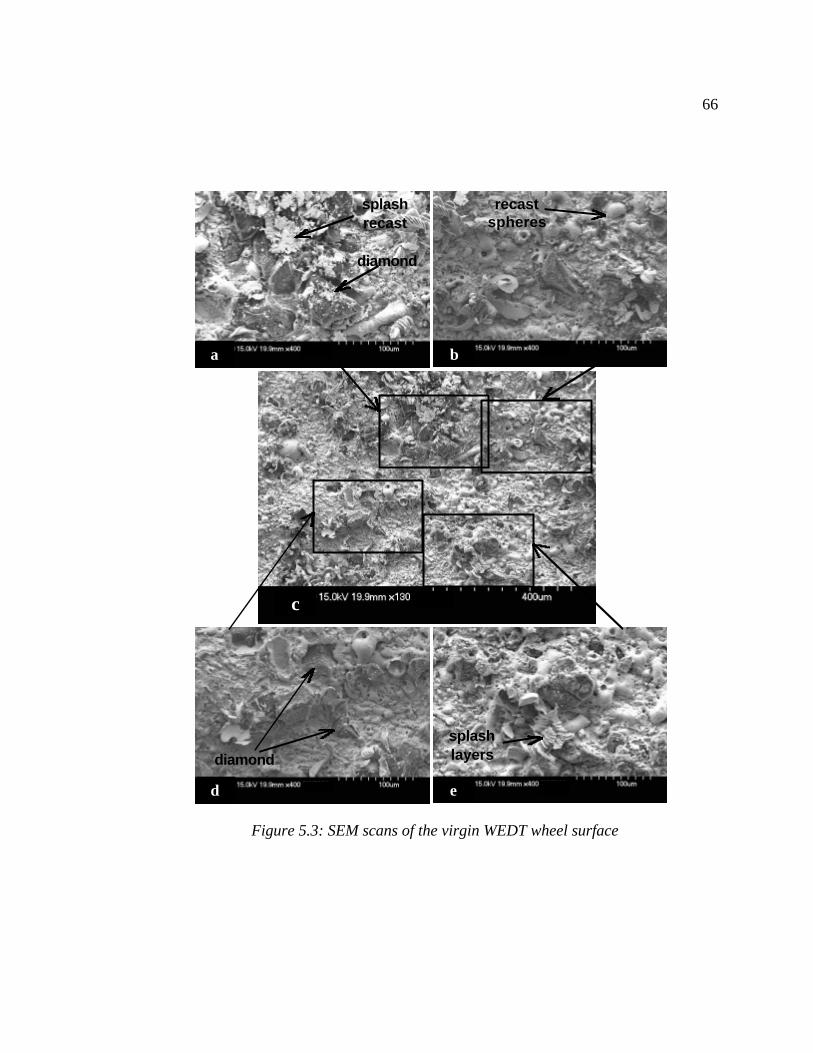
66
d
c
b
Figure 5.3: SEM scans of the virgin WEDT wheel surface
a
e
recast spheres
splash layers
diamond
diamond
splash recast
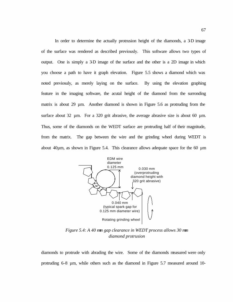
67
In order to determine the actually protrusion height of the diamonds, a 3-D image
of the surface was rendered as described previously. This software allows two types of
output. One is simply a 3-D image of the surface and the other is a 2D image in which
you choose a path to have it graph elevation. Figure 5.5 shows a diamond which was
noted previosuly, as merely laying on the surface. By using the elevation graphing
feature in the imaging software, the acutal height of the diamond from the surronding
matrix is about 29 µm. Another diamond is shown in Figure 5.6 as protruding from the
surface about 32 µm. For a 320 grit abrasive, the average abrasive size is about 60 µm.
Thus, some of the diamonds on the WEDT surface are protruding half of their magnitude,
from the matrix. The gap between the wire and the grinding wheel during WEDT is
about 40µm, as shown in Figure 5.4. This clearance allows adequate space for the 60 µm
diamonds to protrude with abrading the wire. Some of the diamonds measured were only
protruding 6-8 µm, while others such as the diamond in Figure 5.7 measured around 10-
EDM wirediameter0.125 mm
0.040 mm(typical spark gap for
0.125 mm diameter wire)
Rotating grinding wheel
0.030 mm(overprotruding
diamond height with 320 grit abrasive)
Figure 5.4: A 40 µm gap clearance in WEDT process allows 30 µm diamond protrusion
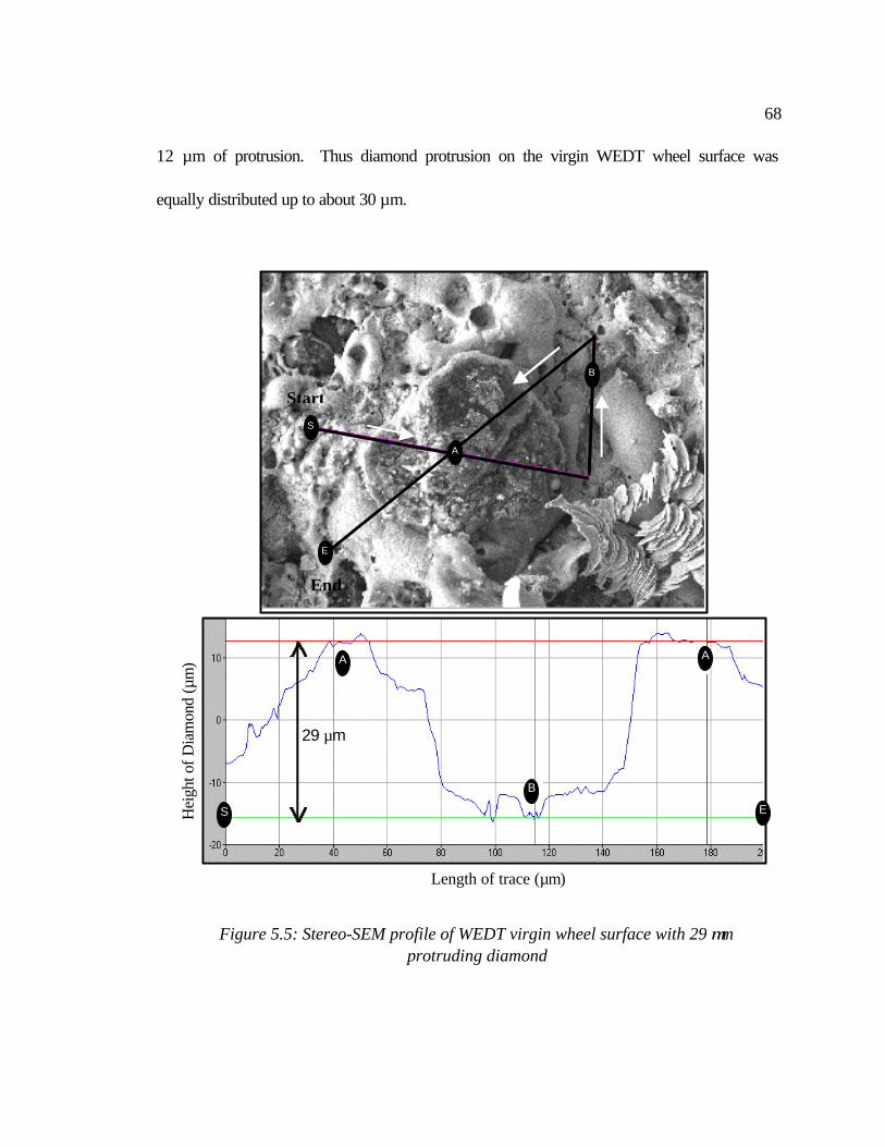
68
12 µm of protrusion. Thus diamond protrusion on the virgin WEDT wheel surface was
equally distributed up to about 30 µm.
Hei
ght o
f Dia
mon
d (µ
m)
Figure 5.5: Stereo-SEM profile of WEDT virgin wheel surface with 29 µm
protruding diamond
Length of trace (µm)
B
A
29 µm
Start
E
End
A
E
B
S
A
A
E
B
S
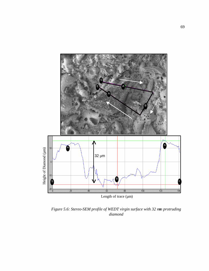
69
Length of trace (µm)
S
Figure 5.6: Stereo-SEM profile of WEDT virgin surface with 32 µm protruding
diamond
Hei
ght o
f Dia
mon
d (µ
m)
B
A A
32 µm
E
Start
End
E
A
B
A
A
E
B
S
A
S
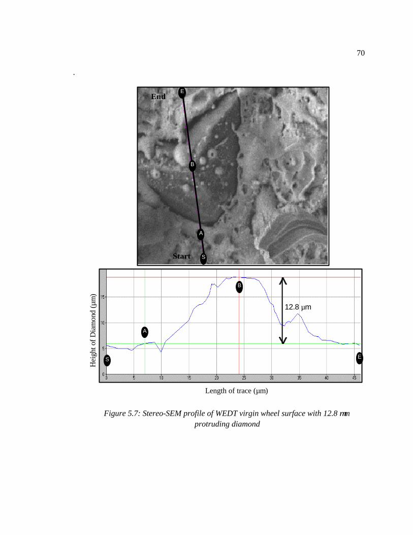
70
.
Figure 5.7: Stereo-SEM profile of WEDT virgin wheel surface with 12.8 µm protruding diamond
Hei
ght o
f Dia
mon
d (µ
m)
Length of trace (µm)
12.8 µm
S
Start
End
B
A
S E
B
A
S
E
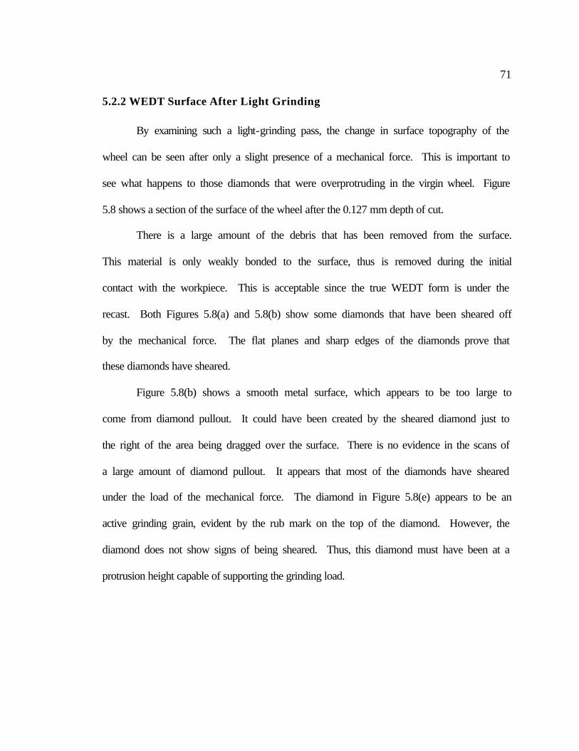
71
5.2.2 WEDT Surface After Light Grinding
By examining such a light-grinding pass, the change in surface topography of the
wheel can be seen after only a slight presence of a mechanical force. This is important to
see what happens to those diamonds that were overprotruding in the virgin wheel. Figure
5.8 shows a section of the surface of the wheel after the 0.127 mm depth of cut.
There is a large amount of the debris that has been removed from the surface.
This material is only weakly bonded to the surface, thus is removed during the initial
contact with the workpiece. This is acceptable since the true WEDT form is under the
recast. Both Figures 5.8(a) and 5.8(b) show some diamonds that have been sheared off
by the mechanical force. The flat planes and sharp edges of the diamonds prove that
these diamonds have sheared.
Figure 5.8(b) shows a smooth metal surface, which appears to be too large to
come from diamond pullout. It could have been created by the sheared diamond just to
the right of the area being dragged over the surface. There is no evidence in the scans of
a large amount of diamond pullout. It appears that most of the diamonds have sheared
under the load of the mechanical force. The diamond in Figure 5.8(e) appears to be an
active grinding grain, evident by the rub mark on the top of the diamond. However, the
diamond does not show signs of being sheared. Thus, this diamond must have been at a
protrusion height capable of supporting the grinding load.
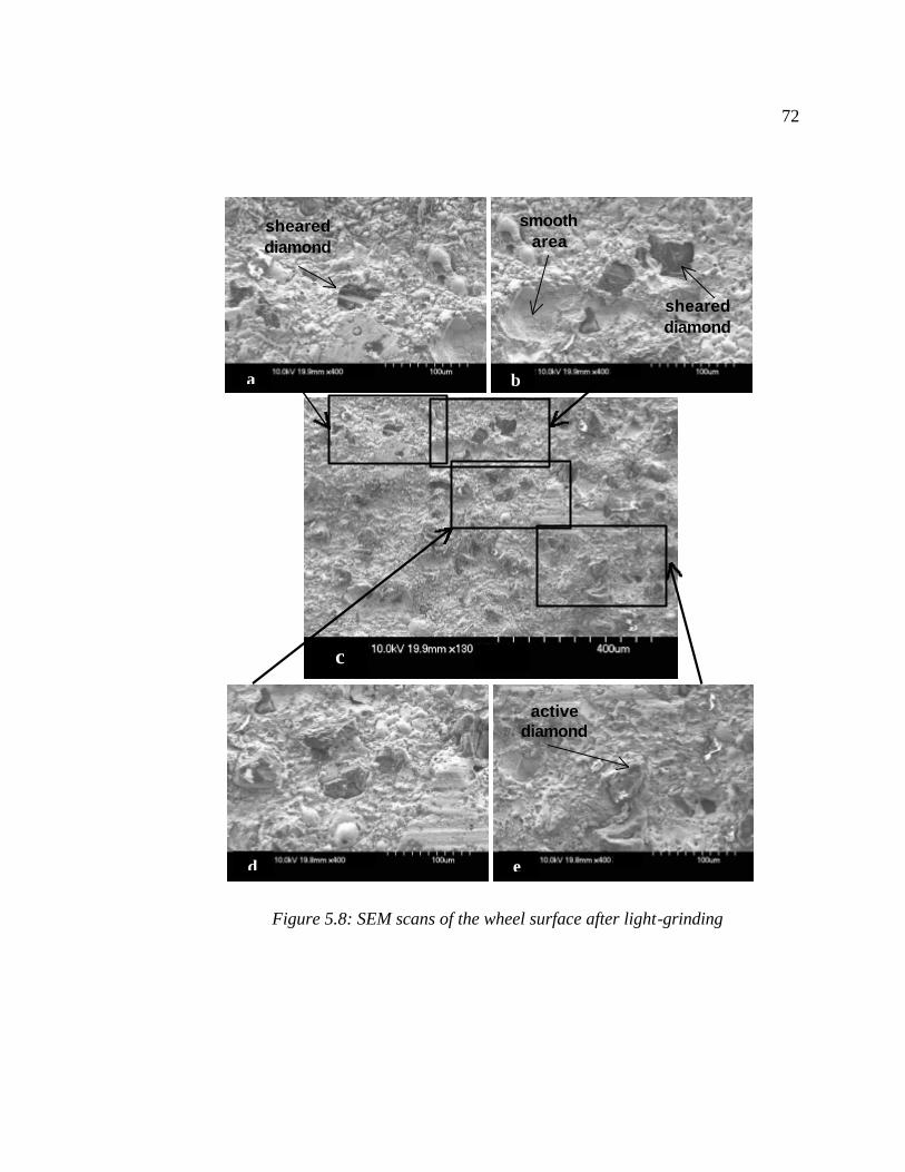
72
Figure 5.8: SEM scans of the wheel surface after light-grinding
e
a b
c
d
sheared diamond
active diamond
smooth area
sheared diamond
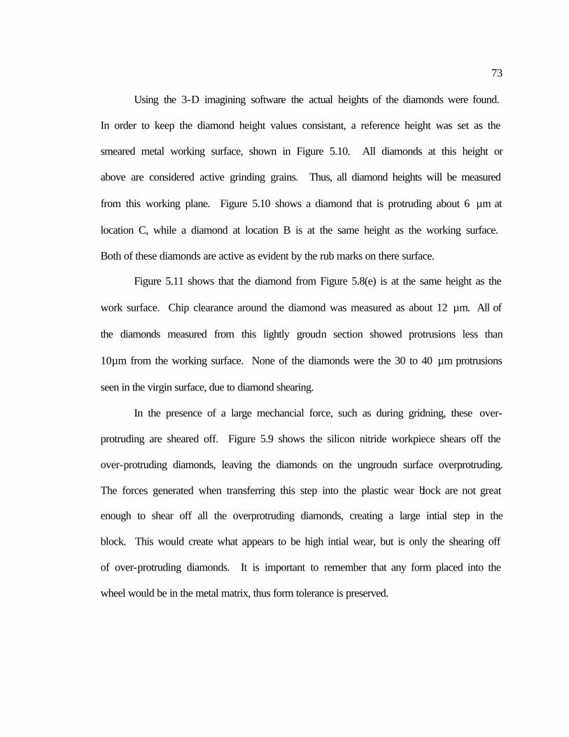
73
Using the 3-D imagining software the actual heights of the diamonds were found.
In order to keep the diamond height values consistant, a reference height was set as the
smeared metal working surface, shown in Figure 5.10. All diamonds at this height or
above are considered active grinding grains. Thus, all diamond heights will be measured
from this working plane. Figure 5.10 shows a diamond that is protruding about 6 µm at
location C, while a diamond at location B is at the same height as the working surface.
Both of these diamonds are active as evident by the rub marks on there surface.
Figure 5.11 shows that the diamond from Figure 5.8(e) is at the same height as the
work surface. Chip clearance around the diamond was measured as about 12 µm. All of
the diamonds measured from this lightly groudn section showed protrusions less than
10µm from the working surface. None of the diamonds were the 30 to 40 µm protrusions
seen in the virgin surface, due to diamond shearing.
In the presence of a large mechancial force, such as during gridning, these over-
protruding are sheared off. Figure 5.9 shows the silicon nitride workpiece shears off the
over-protruding diamonds, leaving the diamonds on the ungroudn surface overprotruding.
The forces generated when transferring this step into the plastic wear block are not great
enough to shear off all the overprotruding diamonds, creating a large intial step in the
block. This would create what appears to be high intial wear, but is only the shearing off
of over-protruding diamonds. It is important to remember that any form placed into the
wheel would be in the metal matrix, thus form tolerance is preserved.
74
SILICON NITRIDE
Grinding Wheel
Grinding Wheel
overprotruding diamonds
sheared diamond grits
Figure 5.9: Diagram of diamonds sheared during grinding
unsheared diamondgrits
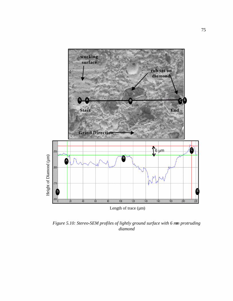
75
Figure 5.10: Stereo-SEM profiles of lightly ground surface with 6 µm protruding
diamond
Hei
ght o
f Dia
mon
d (µ
m)
Length of trace (µm)
6 µm
Start End
rub sot on diamond
working surface
Grind Direction
B A
S E
C
CAS E B
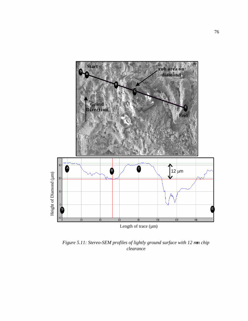
76
Figure 5.11: Stereo-SEM profiles of lightly ground surface with 12 µm chip
clearance
Hei
ght o
f Dia
mon
d (µ
m)
Length of trace (µm)
12 µm
Start
End
S
rub area on diamond
Grind Direction
B A
E
C
B
A
E
C
S
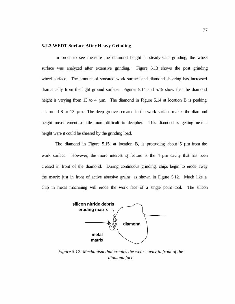
77
5.2.3 WEDT Surface After Heavy Grinding
In order to see measure the diamond height at steady-state grinding, the wheel
surface was analyzed after extensive grinding. Figure 5.13 shows the post grinding
wheel surface. The amount of smeared work surface and diamond shearing has increased
dramatically from the light ground surface. Figures 5.14 and 5.15 show that the diamond
height is varying from 13 to 4 µm. The diamond in Figure 5.14 at location B is peaking
at around 8 to 13 µm. The deep grooves created in the work surface makes the diamond
height measurement a little more difficult to decipher. This diamond is getting near a
height were it could be sheared by the grinding load.
The diamond in Figure 5.15, at location B, is protruding about 5 µm from the
work surface. However, the more interesting feature is the 4 µm cavity that has been
created in front of the diamond. During continuous grinding, chips begin to erode away
the matrix just in front of active abrasive grains, as shown in Figure 5.12. Much like a
chip in metal machining will erode the work face of a single point tool. The silicon
diamond
metal matrix
silicon nitride debris eroding matrix
Figure 5.12: Mechanism that creates the wear cavity in front of the diamond face
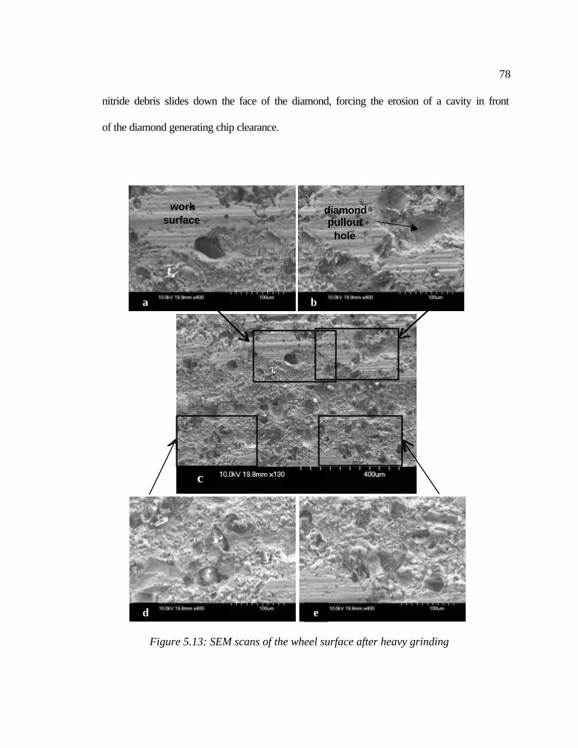
78
nitride debris slides down the face of the diamond, forcing the erosion of a cavity in front
of the diamond generating chip clearance.
c
Figure 5.13: SEM scans of the wheel surface after heavy grinding
a
d
b
e
work surface
diamond pullout
hole
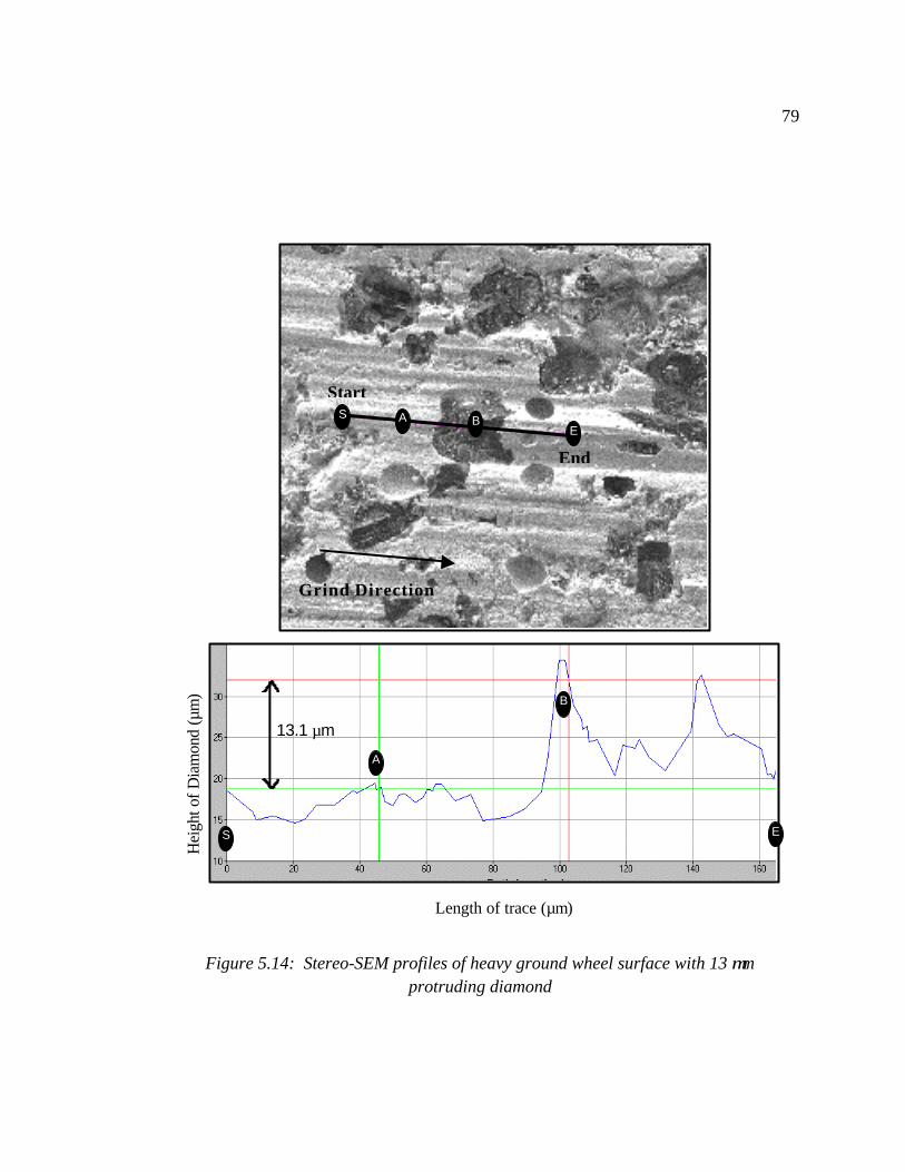
79
Hei
ght o
f Dia
mon
d (µ
m)
Figure 5.14: Stereo-SEM profiles of heavy ground wheel surface with 13 µm
protruding diamond
Length of trace (µm)
13.1 µm
Start
End
Grind Direction
B
A
E S
B AE
S
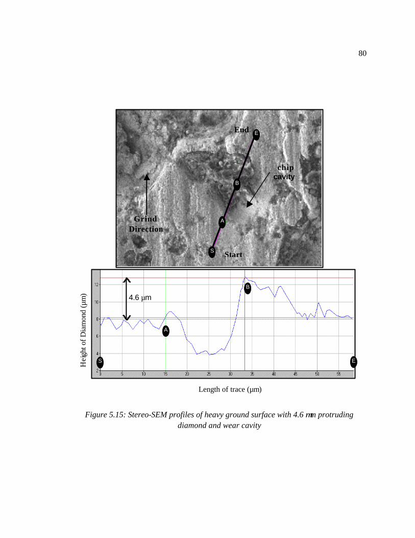
80
Figure 5.15: Stereo-SEM profiles of heavy ground surface with 4.6 µm protruding diamond and wear cavity
Hei
ght o
f Dia
mon
d (µ
m)
Length of trace (µm)
4.6 µm
Start
End
chip cavity
Grind Direction
B
A
E S
B
A
E
S
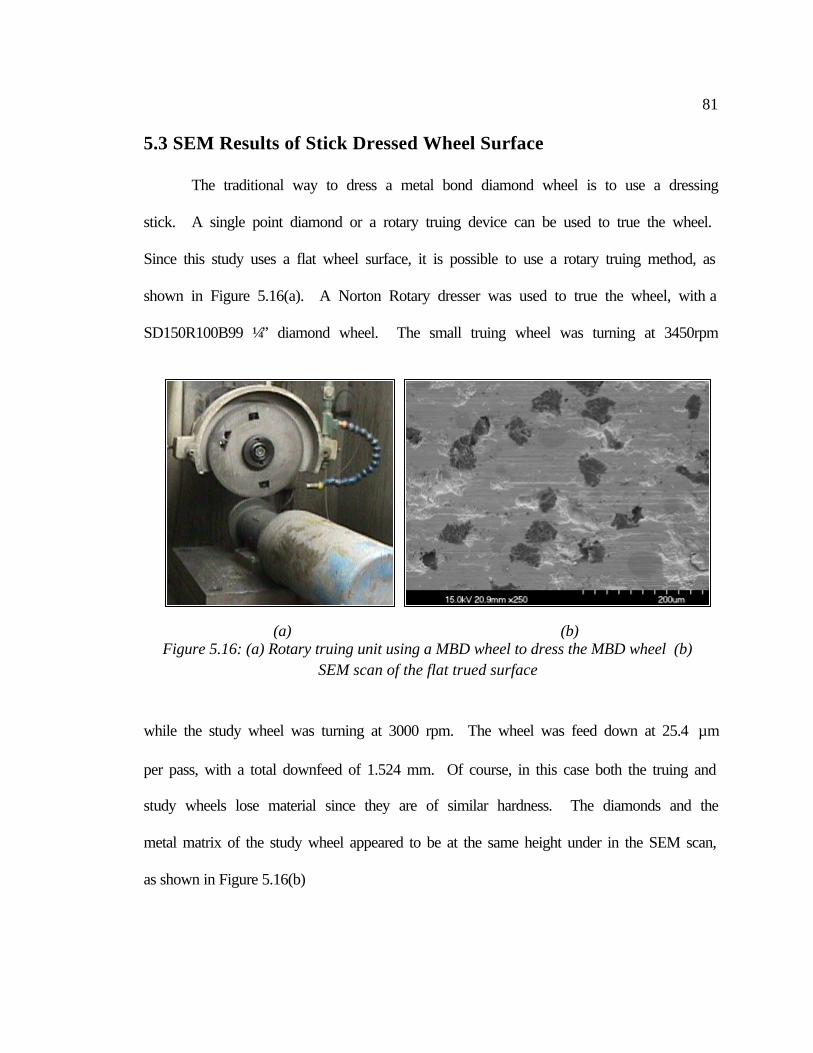
81
5.3 SEM Results of Stick Dressed Wheel Surface
The traditional way to dress a metal bond diamond wheel is to use a dressing
stick. A single point diamond or a rotary truing device can be used to true the wheel.
Since this study uses a flat wheel surface, it is possible to use a rotary truing method, as
shown in Figure 5.16(a). A Norton Rotary dresser was used to true the wheel, with a
SD150R100B99 ¼” diamond wheel. The small truing wheel was turning at 3450rpm
while the study wheel was turning at 3000 rpm. The wheel was feed down at 25.4 µm
per pass, with a total downfeed of 1.524 mm. Of course, in this case both the truing and
study wheels lose material since they are of similar hardness. The diamonds and the
metal matrix of the study wheel appeared to be at the same height under in the SEM scan,
as shown in Figure 5.16(b)
(a) (b) Figure 5.16: (a) Rotary truing unit using a MBD wheel to dress the MBD wheel (b)
SEM scan of the flat trued surface
82
Once the wheel was trued it was time to dress the wheel using a silicon carbide
dressing stick. Both a fine 400 grit and a rough 150 grit stone were used to dress a
portion of the wheel. During truing, a total of 7.74 cm2/unit width of dressing stick was
consumed. After comparing the differences in the dressed surfaces, no noticeable
difference was found. Therefore the distinction between the two surfaces will not be
stated, it will simply be referred to as the stick dressed surfaced. Figure 5.17 shows the
SEM scans of the stick dressed surface, notice the relatively clean surface of the wheel,
as compared to the WEDT wheel.
Due to the use of the mechanical force during truing, the diamonds and matrix
were on the same plane. Then the stick was used only to create a chip clearance around
the diamonds. The silicon carbide stick is strong enough to erode the metal matrix, but
not the diamond. Thus after dressing, the diamonds will be protruding a certain distance
from the surface.
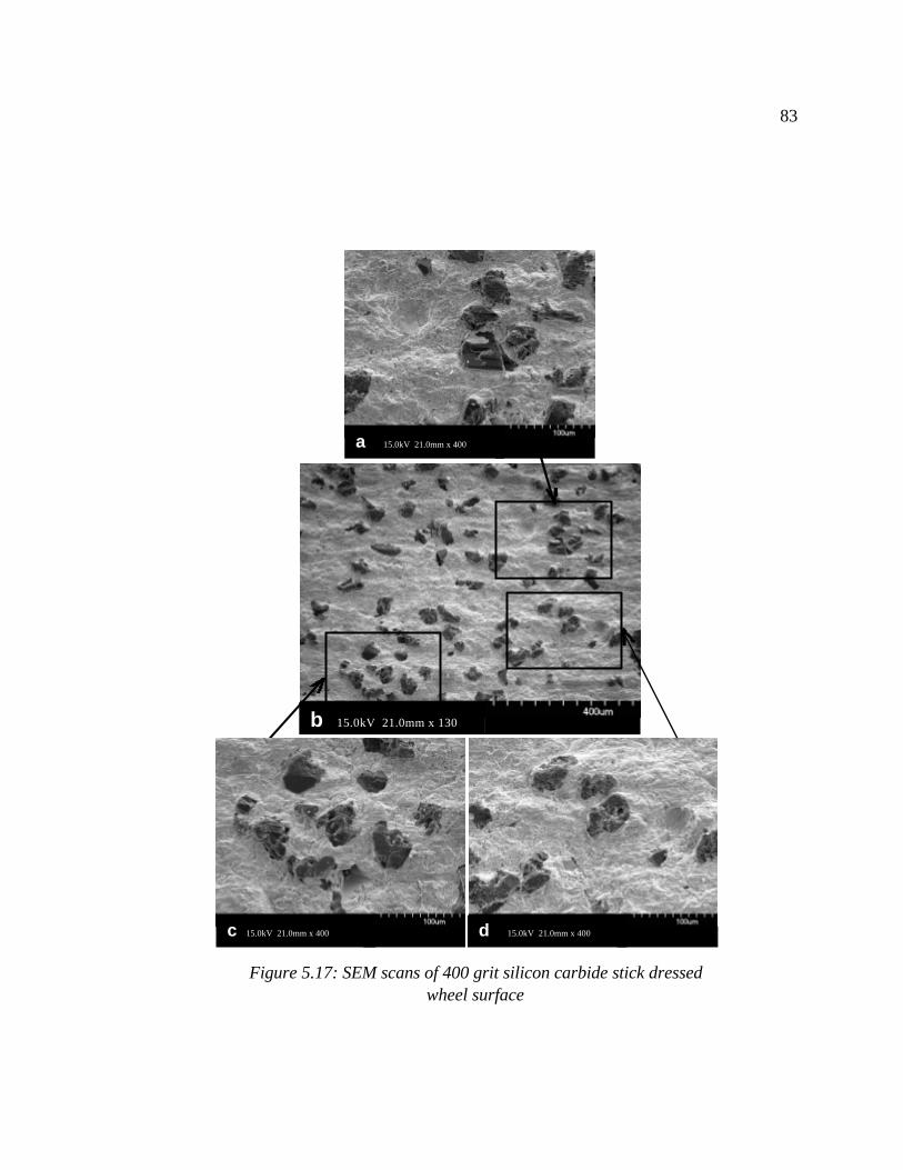
83
a 15.0kV 21.0mm x 400
b 15.0kV 21.0mm x 130
Figure 5.17: SEM scans of 400 grit silicon carbide stick dressed wheel surface
c 15.0kV 21.0mm x 400 d 15.0kV 21.0mm x 400
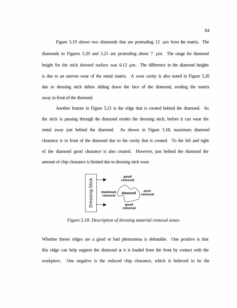
84
Figure 5.19 shows two diamonds that are protruding 12 µm from the matrix. The
diamonds in Figures 5.20 and 5.21 are protruding about 7 µm. The range for diamond
height for the stick dressed surface was 6-12 µm. The difference in the diamond heights
is due to an uneven wear of the metal matrix. A wear cavity is also noted in Figure 5.20
due to dressing stick debris sliding down the face of the diamond, eroding the matrix
away in front of the diamond.
Another feature in Figure 5.21 is the ridge that is created behind the diamond. As
the stick is passing through the diamond erodes the dressing stick, before it can wear the
metal away just behind the diamond. As shown in Figure 5.18, maximum diamond
clearance is in front of the diamond due to the cavity that is created. To the left and right
of the diamond good clearance is also created. However, just behind the diamond the
amount of chip clearance is limited due to dressing stick wear.
Whether theses ridges are a good or bad phenomena is debatable. One positive is that
this ridge can help support the diamond as it is loaded from the front by contact with the
workpiece. One negative is the reduced chip clearance, which is believed to be the
diamond
good removal
good removal
maximumremoval
poor removal
Dre
ssin
g S
tick
Figure 5.18: Description of dressing material removal zones
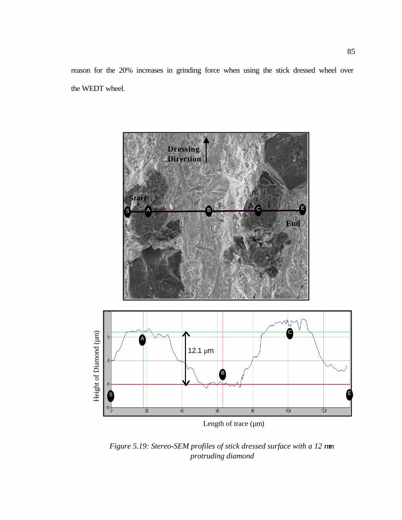
85
reason for the 20% increases in grinding force when using the stick dressed wheel over
the WEDT wheel.
H
eigh
t of D
iam
ond
(µm
)
Figure 5.19: Stereo-SEM profiles of stick dressed surface with a 12 µm
protruding diamond
Length of trace (µm)
12.1 µm
Start
End
Dressing Direction
B
A
E S
C
B A E S C
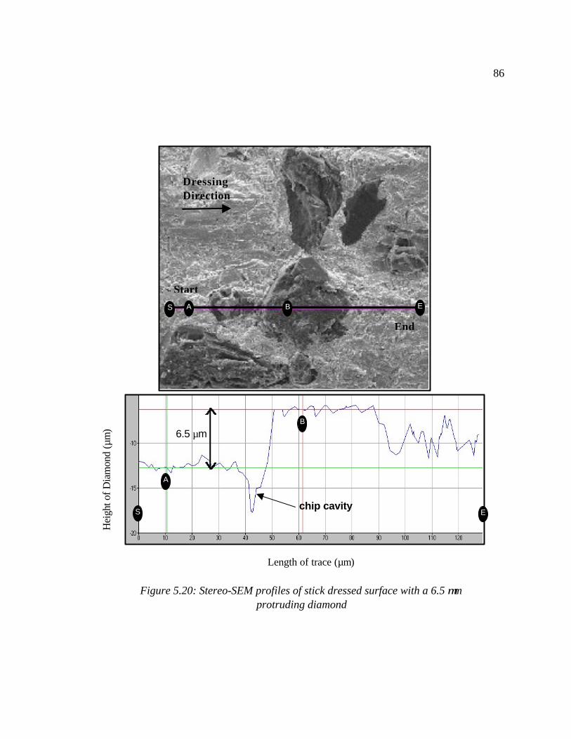
86
Figure 5.20: Stereo-SEM profiles of stick dressed surface with a 6.5 µm
protruding diamond
Hei
ght o
f Dia
mon
d (µ
m)
Length of trace (µm)
6.5 µm
Start
End
Dressing Direction
B
A
E S chip cavity
B A E S
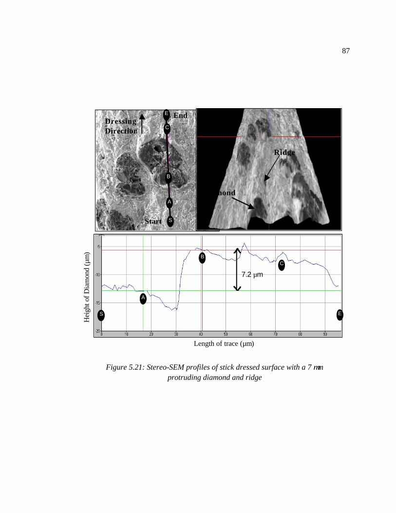
87
Figure 5.21: Stereo-SEM profiles of stick dressed surface with a 7 µm protruding diamond and ridge
Hei
ght o
f Dia
mon
d (µ
m)
Length of trace (µm)
7.2 µm
Start
End DressingDirection
Diamond
Ridge
B
A
E S
C
C
B
A
E
S
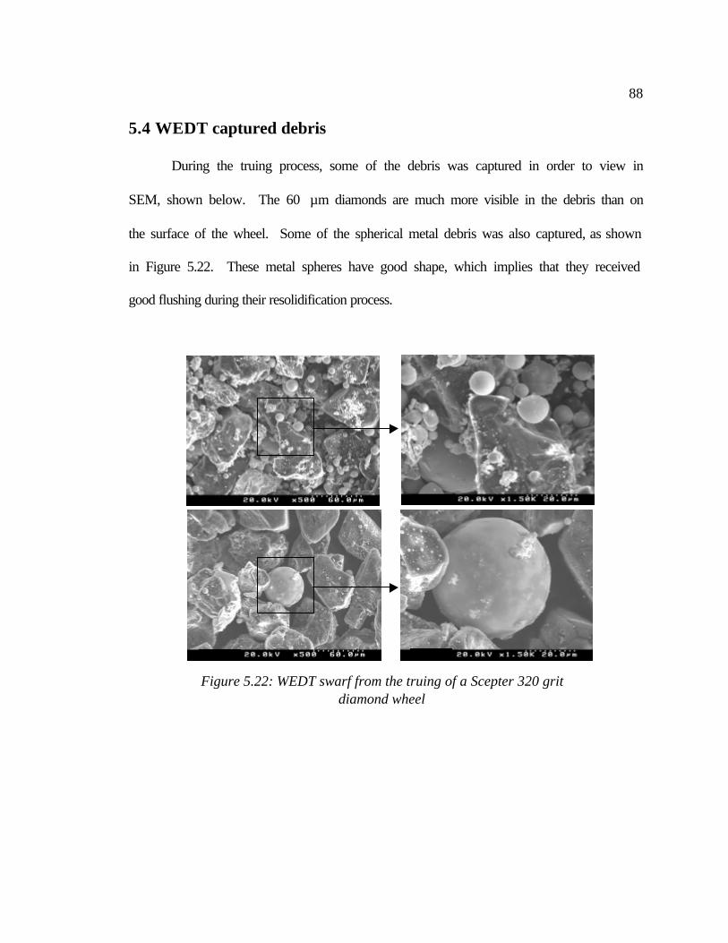
88
5.4 WEDT captured debris
During the truing process, some of the debris was captured in order to view in
SEM, shown below. The 60 µm diamonds are much more visible in the debris than on
the surface of the wheel. Some of the spherical metal debris was also captured, as shown
in Figure 5.22. These metal spheres have good shape, which implies that they received
good flushing during their resolidification process.
Figure 5.22: WEDT swarf from the truing of a Scepter 320 grit diamond wheel
89
5.5 Conclusion of SEM investigation
For the WEDT surface there was evidence to show that some of the molten metal
spheres had adhered back to the surface of the wheel. The height of the diamonds on the
virgin surface varied from 3 to 35 µm. When a light grind was used, the diamonds were
all protruding less than 13 µm from the work surface. At the large grinding depth, the
diamonds were protruding 4 to 13 µm from the working surface. Due to the number of
sheared diamonds, the theory for high initial wear due to shearing of overprotruding
diamonds is proven.
Contrary to the rough surface of the WEDT wheel, the surface on the rotary
diamond trued and silicon carbide stick dressed wheel was smooth. The range of
diamond heights from this surface ranged from 6 to 10 µm. Two demographic features
noted about the surface, are the ridge created behind the diamond and the cavity created
in front of the diamond face. The ridge, while it supports the diamond during force
loading, also reduces the amount of chip clearance. This is thought to be the reason why
the WEDT wheel grinds more freely than does the stick dressed wheel.
The major problem with rotary dressing is its inability to create a formed profile
in the wheel. In order to create a profile in a wheel surface a single point CNC controlled
diamond or a diamond crush roll must be used. As mentioned previously, neither of
these methods are effective for creating precision forms due to truing tool wear.
90
6 CONCLUSION
As the applications of engineering ceramics broadened, the shape of these
components has become more complicated and the form tolerance specifications are
more stringent. An efficient and cost-effective method to grind a ceramic component
with a complicated shape is to generate the desired form on a diamond grinding wheel
and then plunge the shaped wheel into the ceramic workpiece. The excess ceramic work-
material is removed by the diamond grinding wheel, and the desired form is generated on
the workpiece. Based on this approach, the technical challenge has shifted from grinding
the workpiece to truing and dressing the diamond grinding wheel.
Traditionally, a stationary or rotary diamond tool is used to generate the desired
form in a grinding wheel. Shih [2000] has studied the wear of the rotary diamond tool for
truing of a vitreous bond diamond grinding wheel and demonstrated that the wear of
diamond tool is significant under a wide range of process parameters. Instead of using
mechanical force to break the diamond, the wire EDM process uses the thermal energy or
electrical sparks between a thin, traveling wire and the rotating grinding wheel to remove
the metal bond around the non-conductive diamond abrasive. The Japanese patents by
Mizukawa [1992], Shichizawa [1993], and Oku [1984] all use rotary die sinking EDM
truing methods. However, not much work has been focused on creating precise wheel
forms, which was at the core of this investigation.
The begin the research, a precision spindle was built to rotate the grinding wheel
inside the EDM machine during truing. The spindle had to endure the corrosive and high
electrical flow environments of the EDM process. In addition, the spindle was desired to
91
have sub-µm runout and also to be capable of incorporating varies wheel sizes. The final
design met all of the criteria and achieved a spindle runout of 0.6 µm.
Two formed wheel geometries were then adopted in order to determine the
abilities of Wire Electrical Discharge Truing (WEDT). A peak-valley profile was
implemented to determine the minimal inner and outer part radii that could be achieved.
The minimum peak radius for a part was about 108 µm, while 82 µm was the minimum
radius for a valley in the component. The form error capability of the WEDT procedure
was determined using an arc profile. Two cutoff values, 0.08 and 0.25 mm, were used to
filter the trace data, which gave form error results of 6.5 and 2.4 µm, respectively.
To determine the performance of the WEDT wheel, a grinding study was
developed. Force and power during grinding was collected using a Hall-effect power
sensor, a force dynamometer, and a data acquisition system. A plastic wear block was
used to quantify the progressive wheel wear. The ground ceramic tiles were used to
quantify surface roughness trends. The test included two truing methods for comparison.
One of the wheels was trued using a single point diamond, while the WEDT process
presented in this report trued the other wheel. The WEDT wheel required no additional
preparation, since the EDM process completes both truing and dressing simultaneously.
The single point trued wheel was dressed with a silicon carbide stick to create chip
clearance.
The forces generated during grinding with the WEDT wheel were 20-40% lower
than the forces produced when grinding with the single point trued, stick dressed wheel.
Wheel breakdown occurred after 6 ground parts using the stick dressed wheel. It took
92
about 15 passes before the EDM trued wheel began to breakdown. Surface finish on the
ground parts were all very similar for both truing methods. The average surface
roughness results were below 1 µm, while the peak-to-valley results ranged from 3-5 µm.
Roughness of the ground parts decreased as the number of passes increased as expected,
due to an increase in the diamond wear flats. The high initial wear of the EDM trued
wheel created the most concern. After the intial grinding pass, the wheel wear stablized
to around 2 µm/pass. Scanning Electron Microscopy (SEM) was required to investigate
theories behind this decrease in force and increase in wheel wear when grinding with an
EDM trued wheel.
In the SEM scans, there was evidence to show that some of the molten metal
spheres had adhered back to the surface of the WEDT wheel. The height of the diamonds
on the virgin surface varied from 3 to 35 µm. When a light grind was used, the diamonds
were all protruding less than 13 µm from the work surface. At steady-state grinding, the
diamonds were protruding 4 to 13 µm from the working surface. This lead to the
conclusion that the diamonds in the virgin WEDT wheel surface are overprotruding.
Thus, in the presence of a sufficient mechanical force they will shear. There was plenty
of sheared diamond surfaces in the lightly ground SEM scans to prove this theory.
However, the form has been placed in the metal matrix, thus shearing of overprotruding
diamonds does not effect the form tolerance.
Also at steady state grinding, 4 to 5 µm cavities were found in front of the
diamond faces. The grinding debris creates these cavities as it slides down the face of the
diamond, eroding the matrix just preceding the diamond. Contrary to the rough surface
93
of the WEDT wheel, the surface on the diamond trued and silicon carbide stick dressed
wheel was smooth. The range of diamond heights from this surface ranged from 6 to 10
µm. Two demographic features noted about the surface were the ridges created behind
the diamonds and the cavities created in front of the diamond faces. As the dressing stick
passes over the diamond, the stick becomes worn. Therefore, the dressing stick does not
remove the metal just behind the diamond. This reduction in chip clearance and extreme
diamond protrusion is believed to be the reason for the reduced grinding forces of the
WEDT wheel.
In this study, WEDT has proven its ability to produce precise forms in metal bond
diamond wheels. In grinding, WEDT wheels also showed a decrease in grinding force,
as well as an increase in the dressing interval. Through the use of an electrical spark
instead of a mechanical force, the wheels can be trued/dressed without concerns of truing
tool wear. This wheel forming technology should serve even more valuable to the
machining community as the number of ceramics in engineering design increases.
94
REFERENCES
Almedia, J. Breaking Wire EDM Rules. American Machining Auto. Manufacturing. v130 n11, 1986. Banyapodha, B. Personal interview. July, 2000 at Cummins Engine Company. Professor at North Dakota State University in Machining Process. Barrett, C. Wheel Profiling with EDM. Industrial Diamond Review. v47 n521, 1987. Breton, B. The Early History and Development of The Scanning Electron Microscope. Website of Online Information, 2001. http://www2.eng.cam.ac.uk/~bcb/history.html. Cookall, J. and Khor, B. Electro-Discharge Machined Surfaces, Proceedings of 15th International Machine Tool Design Research, 1974. Malkin, S. Comparison of Single Point and Rotary Dressing of Grinding Wheels. 5th North American Metalworking Research Conference, 1977. Malkin, S. Grinding Technology: theory and applications of machining with abrasives. Ellis Horwood Limited: Chichester, England: 1989. Mizukawa, T. and Niima, H. Machining Method With Discharge Truing. Patent Number JP6008141A2, 1992. Nakagawa, T., Suzuki, K., Uematsu, T., Shimizu, N., and Takada, Y. Turning Center with Electric Discharge Truing/Dressing Device. Patent Number JP1040274A2, 1989. Oku, T and Suzuki, Y. Dressing Method of Cutting Wheel. Patent number JP59088255A2, 1984. Precision Devices - Online Metrology Guide. Website of Online Information, 2001. http://www.predev.com/smg/intro.htm. Qian, J., Li, W., and Ohmori, H. Precision internal grinding with a metal-bonded diamond grinding wheel. Journal-of-Materials-Processing-Technology. v105 n1, 2000. Rajurkar, K. and Pandit S. Recent Progress in Electrical Discharge Machine Technology and Research. Proceedings of Manufacturing International. v1, 1988. Rajurkar, K. University of Nebraska at Lincoln. Website of Online Information, 2001. http://www.unl.edu/nmrc/Processmech/Processmech.htm.
95
Shichizawa, S. Dressing Method For Electrode in Electric Discharge Machining and Electric Discharge Machine. Patent number JP5077111A2, 1993. Shih, A. and Akemon, J. Wear of Blade Diamond Tools in Truing Vitreous Bond Grinding Wheels. Submitted to Machining Science and Technology, 2001. Shih, A. and Yonushonis, T. High infeed rate method for grinding ceramic workpieces with silicon carbide grinding wheels. Patent number 6030277, 2000. Shih, A. Rotary Truing of Vitreous Bond Diamond Grinding Wheels Using Metal Bond Diamond Disk. Machining Science and Technology. v2 n1, 1998. Sun-Diamond Powder for Grinding Wheel. Website of Online Information, 2001. http://www.smg-diamond.com/grind.html. Suzuki, K., Uematsu, T., and Nakagawa, T. On-Machine Trueing/Dressing of Metal Bond Diamond Grinding Wheels By Electro-Discharge Machining. CIRP-Annals. v36 n1, 1987. Thompson, D. Grinding Wheel Topography and Undeformed Chip Shape. Proceedings of the International Conference of Production Engineering, 1974. Wang, X., Ying, B., and Liu, W. EDM dressing of fine grain super abrasive grinding wheels. Journal-of-Materials-Processing-Technology. v62 n4, 1996. Welch, E. and Yi, Y. and Bifano, T. Electrochemical dressing of bronze bonded diamond grinding wheels. NIST-Special-Publication. n847, 1993. Williams, R. and Rajurkar, K. Study of Wire Electrical Discharge Machined Surface Characteristics. Journal of Mechanical Processing Technology, v28, 1991. Zhang, J., Ai, X., Lee, K., and Wong, P. Study on electro-discharge diamond wheel grinding (EDGM) of ceramic materials. Materials-and-Manufacturing-Processes. v11 n5, 1996. Zhang,C., Ohmori, H., and Li, W. Small-hole machining of ceramic material with electrolytic interval-dressing (ELID-II) grinding. Journal of Materials Processing Technology. v105 n3, 2000.