Embed Size (px)
Citation preview
865
Related Information
Selection Guide
Amplifier Built-in
Amplifier-separated
GX-F/H
GXL
GL
GX-MGX-U/GX-FU/
GX-NGX
FIBERSENSORS
LASERSENSORS
PHOTOELECTRICSENSORS
MICROPHOTOELECTRIC
SENSORS
AREASENSORS
LIGHT CURTAINS /SAFETY
COMPONENTSPRESSURE /
FLOWSENSORS
INDUCTIVEPROXIMITY
SENSORS
PARTICULARUSE SENSORS
SENSOROPTIONS
SIMPLEWIRE-SAVING
UNITS
WIRE-SAVING SYSTEMS
MEASUREMENTSENSORS
STATIC ELECTRICITYPREVENTION
DEVICES
LASERMARKERS
PLC
HUMAN MACHINE INTERFACES
ENERGY CONSUMPTION VISUALIZATION COMPONENTS
FA COMPONENTS
MACHINE VISION SYSTEMS
UV CURING SYSTEMS
Miniature GX-3S□
GX-3S□ is an amplifier built-in inductive proximity sensor having a diameter of just ø3.8 mm ø0.150 in.
VARIETIES
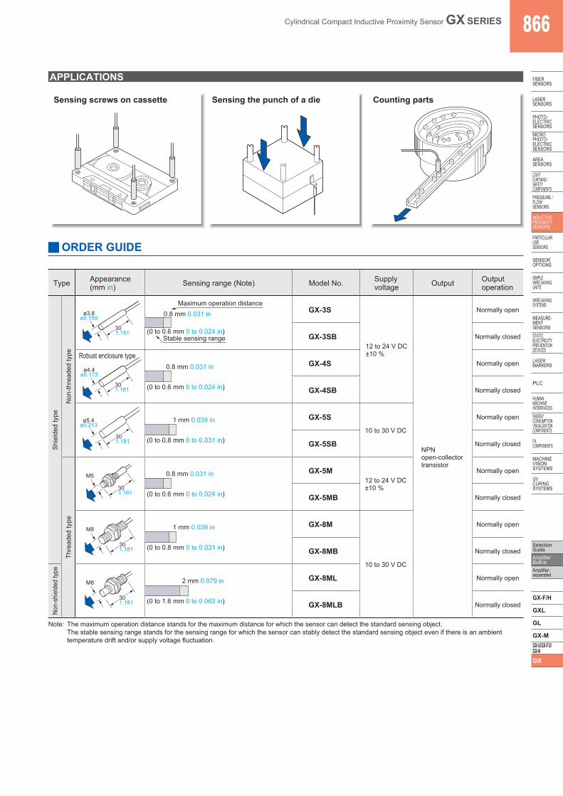
Robust housing GX-4S□
The GX-4S□ uses a robust stainless steel enclosure. The tightening torque can be 0.58 N·m or less.(2 times compared with conventional models)
ø3.8 mm ø0.150 in
Tightening torque: 0.58 N·m or less
A
Robust enclosure [Stainless steel (SUS304)]
[ø4.4 ø0.173 (length: 30 mm 1.181 in)]Operation indicator (Red)
Set screw tightening positionA: 5 to 10 mm 0.197 to 0.394 in
from the sensor end
Tighten the set screwfrom a direction perpendicularto the operation indicator.
Set screwM3(Cup-point)
BASIC PERFORMANCE
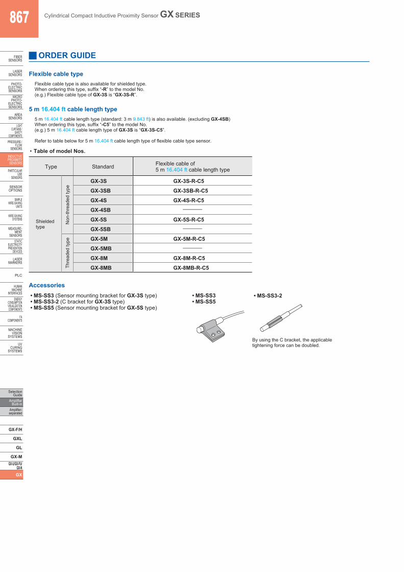
Long sensing range GX-8ML□
The non-shielded type (GX-8ML□) has twice the sensing range of the shielded type (GX-8M□), although having the same size. Hence, it allows margin against sensing distance variations.
1 mm0.039 in
Shielded typeGX-8M□
Non-shielded typeGX-8ML□ 2 mm
0.079 in
Ten times greater bending durability (Compared with conventional models) GX-□-RThe bending durability of the cable to repeated bending has been increased tenfold by using special alloy cores for the cable.
ENVIRONMENTAL RESISTANCE
Conforming toEMC Directive
Flexible cabletype available
Metal embeddingpossible
RecognitionExcluding GX-4S□ and5 m cable length type
Cylindrical Compact Inductive Proximity Sensor Amplifier Built-in
GX SERIES ■General terms and conditions ............. F-7
■Glossary of terms........................ P.1482~ ■General precautions ................... P.1485~
Robust enclosure and flexible cable types are also available
■Sensor selection guide ................. P.803~
panasonic.net/id/pidsx/global
Cylindrical Compact Inductive Proximity Sensor GX SERIES 866
Selection GuideAmplifier Built-inAmplifier-separated
GX-F/H
GXL
GL
GX-MGX-U/GX-FU/GX-NGX
FIBERSENSORS
LASERSENSORS
PHOTO-ELECTRICSENSORSMICROPHOTO-ELECTRICSENSORS
AREASENSORS
LIGHTCURTAINS /SAFETYCOMPONENTSPRESSURE / FLOWSENSORS
INDUCTIVEPROXIMITYSENSORS
PARTICULARUSE SENSORS
SENSOROPTIONS
SIMPLEWIRE-SAVINGUNITS
WIRE-SAVING SYSTEMS
MEASURE-MENTSENSORSSTATIC ELECTRICITYPREVENTIONDEVICES
LASERMARKERS
PLC
HUMAN MACHINE INTERFACESENERGY CONSUMPTION VISUALIZATION COMPONENTS
FA COMPONENTS
MACHINE VISION SYSTEMS
UV CURING SYSTEMS
ORDER GUIDE
APPLICATIONS
Sensing screws on cassette Sensing the punch of a die Counting parts
Type Appearance(mm in) Sensing range (Note) Model No. Supply
voltage Output Outputoperation
Shi
elde
d ty
pe
Non
-thre
aded
type
301.181
ø3.8ø0.150
Maximum operation distance
Stable sensing range
0.8 mm 0.031 in
(0 to 0.6 mm 0 to 0.024 in)
GX-3S
12 to 24 V DC±10 %
NPNopen-collectortransistor
Normally open
GX-3SB Normally closed
Robust enclosure type
ø4.4ø0.173
301.181
0.8 mm 0.031 in
(0 to 0.6 mm 0 to 0.024 in)
GX-4S Normally open
GX-4SB Normally closed
ø5.4ø0.213
301.181
1 mm 0.039 in
(0 to 0.8 mm 0 to 0.031 in)
GX-5S10 to 30 V DC
Normally open
GX-5SB Normally closed
Thre
aded
type
M5
301.181
0.8 mm 0.031 in
(0 to 0.6 mm 0 to 0.024 in)
GX-5M12 to 24 V DC±10 %
Normally open
GX-5MB Normally closed
M8
301.181
1 mm 0.039 in
(0 to 0.8 mm 0 to 0.031 in)
GX-8M
10 to 30 V DC
Normally open
GX-8MB Normally closed
Non-
shie
lded
type
M8
301.181
2 mm 0.079 in
(0 to 1.6 mm 0 to 0.063 in)
GX-8ML Normally open
GX-8MLB Normally closed
Note: The maximum operation distance stands for the maximum distance for which the sensor can detect the standard sensing object. The stable sensing range stands for the sensing range for which the sensor can stably detect the standard sensing object even if there is an ambient temperature drift and/or supply voltage fluctuation.
867 Cylindrical Compact Inductive Proximity Sensor GX SERIES
Selection Guide
Amplifier Built-in
Amplifier-separated
GX-F/H
GXL
GL
GX-MGX-U/GX-FU/
GX-NGX
FIBERSENSORS
LASERSENSORS
PHOTO-ELECTRICSENSORS
MICROPHOTO-
ELECTRICSENSORS
AREASENSORS
LIGHTCURTAINS /
SAFETYCOMPONENTS
PRESSURE / FLOW
SENSORS
INDUCTIVEPROXIMITY
SENSORS
PARTICULARUSE
SENSORS
SENSOROPTIONS
SIMPLEWIRE-SAVING
UNITS
WIRE-SAVING SYSTEMS
MEASURE-MENT
SENSORSSTATIC
ELECTRICITYPREVENTION
DEVICES
LASERMARKERS
PLC
HUMAN MACHINE
INTERFACESENERGY
CONSUMPTION VISUALIZATION COMPONENTS
FA COMPONENTS
MACHINE VISION
SYSTEMS
UV CURING
SYSTEMS
ORDER GUIDE
Flexible cable typeFlexible cable type is also available for shielded type.When ordering this type, suffix “-R” to the model No.(e.g.) Flexible cable type of GX-3S is “GX-3S-R”.
5 m 16.404 ft cable length type5 m 16.404 ft cable length type (standard: 3 m 9.843 ft) is also available. (excluding GX-4SB)When ordering this type, suffix “-C5” to the model No.(e.g.) 5 m 16.404 ft cable length type of GX-3S is “GX-3S-C5”.
Refer to table below for 5 m 16.404 ft cable length type of flexible cable type sensor.
• Table of model Nos.
Type Standard Flexible cable of5 m 16.404 ft cable length type
Shieldedtype
Non
-thre
aded
type
GX-3S GX-3S-R-C5
GX-3SB GX-3SB-R-C5
GX-4S GX-4S-R-C5
GX-4SB –
GX-5S GX-5S-R-C5
GX-5SB –
Thre
aded
type GX-5M GX-5M-R-C5
GX-5MB –
GX-8M GX-8M-R-C5
GX-8MB GX-8MB-R-C5
Accessories• MS-SS3 (Sensor mounting bracket for GX-3S type)• MS-SS3-2 (C bracket for GX-3S type)• MS-SS5 (Sensor mounting bracket for GX-5S type)
• MS-SS3• MS-SS5
• MS-SS3-2
By using the C bracket, the applicabletightening force can be doubled.
Cylindrical Compact Inductive Proximity Sensor GX SERIES 868
Selection GuideAmplifier Built-inAmplifier-separated
GX-F/H
GXL
GL
GX-MGX-U/GX-FU/GX-NGX
FIBERSENSORS
LASERSENSORS
PHOTO-ELECTRICSENSORSMICROPHOTO-ELECTRICSENSORS
AREASENSORS
LIGHTCURTAINS /SAFETYCOMPONENTSPRESSURE / FLOWSENSORS
INDUCTIVEPROXIMITYSENSORS
PARTICULARUSE SENSORS
SENSOROPTIONS
SIMPLEWIRE-SAVINGUNITS
WIRE-SAVING SYSTEMS
MEASURE-MENTSENSORSSTATIC ELECTRICITYPREVENTIONDEVICES
LASERMARKERS
PLC
HUMAN MACHINE INTERFACESENERGY CONSUMPTION VISUALIZATION COMPONENTS
FA COMPONENTS
MACHINE VISION SYSTEMS
UV CURING SYSTEMS
SPECIFICATIONS
Non-threaded type
TypeShielded type
Flexible cable Flexible cable Flexible cable
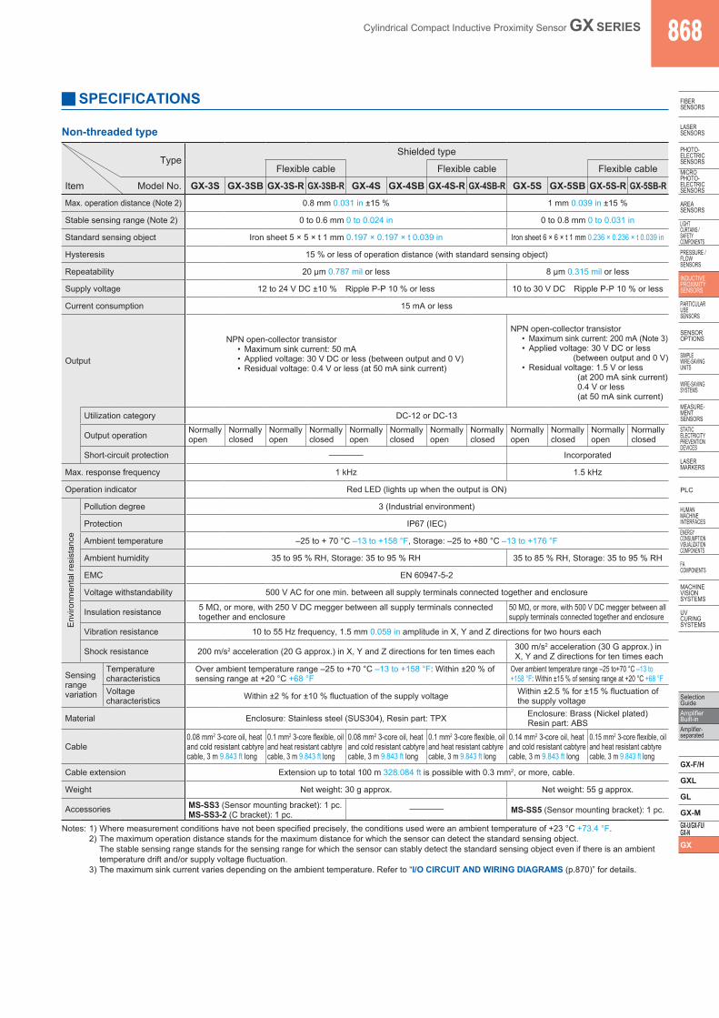
Item Model No. GX-3S GX-3SB GX-3S-R GX-3SB-R GX-4S GX-4SB GX-4S-R GX-4SB-R GX-5S GX-5SB GX-5S-R GX-5SB-RMax. operation distance (Note 2) 0.8 mm 0.031 in ±15 % 1 mm 0.039 in ±15 %
Stable sensing range (Note 2) 0 to 0.6 mm 0 to 0.024 in 0 to 0.8 mm 0 to 0.031 in
Standard sensing object Iron sheet 5 × 5 × t 1 mm 0.197 × 0.197 × t 0.039 in Iron sheet 6 × 6 × t 1 mm 0.236 × 0.236 × t 0.039 in
Hysteresis 15 % or less of operation distance (with standard sensing object)
Repeatability 20 μm 0.787 mil or less 8 μm 0.315 mil or less
Supply voltage 12 to 24 V DC ±10 % Ripple P-P 10 % or less 10 to 30 V DC Ripple P-P 10 % or less
Current consumption 15 mA or less
Output
NPN open-collector transistor• Maximum sink current: 50 mA• Applied voltage: 30 V DC or less (between output and 0 V)• Residual voltage: 0.4 V or less (at 50 mA sink current)
NPN open-collector transistor• Maximum sink current: 200 mA (Note 3)• Applied voltage: 30 V DC or less
(between output and 0 V)• Residual voltage: 1.5 V or less
(at 200 mA sink current) 0.4 V or less (at 50 mA sink current)
Utilization category DC-12 or DC-13
Output operation Normallyopen
Normallyclosed
Normallyopen
Normallyclosed
Normallyopen
Normallyclosed
Normallyopen
Normallyclosed
Normallyopen
Normallyclosed
Normallyopen
Normallyclosed
Short-circuit protection – Incorporated
Max. response frequency 1 kHz 1.5 kHz
Operation indicator Red LED (lights up when the output is ON)
Env
ironm
enta
l res
ista
nce
Pollution degree 3 (Industrial environment)
Protection IP67 (IEC)
Ambient temperature –25 to + 70 °C –13 to +158 °F, Storage: –25 to +80 °C –13 to +176 °F
Ambient humidity 35 to 95 % RH, Storage: 35 to 95 % RH 35 to 85 % RH, Storage: 35 to 95 % RH
EMC EN 60947-5-2
Voltage withstandability 500 V AC for one min. between all supply terminals connected together and enclosure
Insulation resistance 5 MΩ, or more, with 250 V DC megger between all supply terminals connected together and enclosure
50 MΩ, or more, with 500 V DC megger between all supply terminals connected together and enclosure
Vibration resistance 10 to 55 Hz frequency, 1.5 mm 0.059 in amplitude in X, Y and Z directions for two hours each
Shock resistance 200 m/s2 acceleration (20 G approx.) in X, Y and Z directions for ten times each 300 m/s2 acceleration (30 G approx.) in X, Y and Z directions for ten times each
Sensing rangevariation
Temperature characteristics
Over ambient temperature range –25 to +70 °C –13 to +158 °F: Within ±20 % of sensing range at +20 °C +68 °F
Over ambient temperature range –25 to+70 °C –13 to +158 °F: Within ±15 % of sensing range at +20 °C +68 °F
Voltage characteristics Within ±2 % for ±10 % fluctuation of the supply voltage Within ±2.5 % for ±15 % fluctuation of
the supply voltage
Material Enclosure: Stainless steel (SUS304), Resin part: TPX Enclosure: Brass (Nickel plated)Resin part: ABS
Cable0.08 mm2 3-core oil, heat and cold resistant cabtyre cable, 3 m 9.843 ft long
0.1 mm2 3-core flexible, oil and heat resistant cabtyre cable, 3 m 9.843 ft long
0.08 mm2 3-core oil, heat and cold resistant cabtyre cable, 3 m 9.843 ft long
0.1 mm2 3-core flexible, oil and heat resistant cabtyre cable, 3 m 9.843 ft long
0.14 mm2 3-core oil, heat and cold resistant cabtyre cable, 3 m 9.843 ft long
0.15 mm2 3-core flexible, oil and heat resistant cabtyre cable, 3 m 9.843 ft long
Cable extension Extension up to total 100 m 328.084 ft is possible with 0.3 mm2, or more, cable.
Weight Net weight: 30 g approx. Net weight: 55 g approx.
Accessories MS-SS3 (Sensor mounting bracket): 1 pc.MS-SS3-2 (C bracket): 1 pc.
– MS-SS5 (Sensor mounting bracket): 1 pc.
Notes: 1) Where measurement conditions have not been specified precisely, the conditions used were an ambient temperature of +23 °C +73.4 °F.2) The maximum operation distance stands for the maximum distance for which the sensor can detect the standard sensing object.
The stable sensing range stands for the sensing range for which the sensor can stably detect the standard sensing object even if there is an ambient temperature drift and/or supply voltage fluctuation.
3) The maximum sink current varies depending on the ambient temperature. Refer to “I/O CIRCUIT AND WIRING DIAGRAMS (p.870)” for details.
869 Cylindrical Compact Inductive Proximity Sensor GX SERIES
Selection Guide
Amplifier Built-in
Amplifier-separated
GX-F/H
GXL
GL
GX-MGX-U/GX-FU/
GX-NGX
FIBERSENSORS
LASERSENSORS
PHOTO-ELECTRICSENSORS
MICROPHOTO-
ELECTRICSENSORS
AREASENSORS
LIGHTCURTAINS /
SAFETYCOMPONENTS
PRESSURE / FLOW
SENSORS
INDUCTIVEPROXIMITY
SENSORS
PARTICULARUSE
SENSORS
SENSOROPTIONS
SIMPLEWIRE-SAVING
UNITS
WIRE-SAVING SYSTEMS
MEASURE-MENT
SENSORSSTATIC
ELECTRICITYPREVENTION
DEVICES
LASERMARKERS
PLC
HUMAN MACHINE
INTERFACESENERGY
CONSUMPTION VISUALIZATION COMPONENTS
FA COMPONENTS
MACHINE VISION
SYSTEMS
UV CURING
SYSTEMS
TypeShielded type
Non-shielded typeFlexible cable Flexible cable
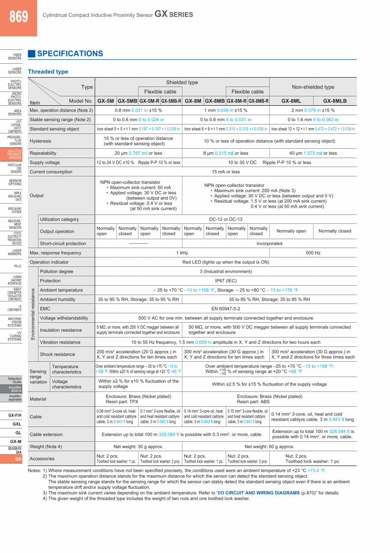
Item Model No. GX-5M GX-5MB GX-5M-R GX-5MB-R GX-8M GX-8MB GX-8M-R GX-8MB-R GX-8ML GX-8MLBMax. operation distance (Note 2) 0.8 mm 0.031 in ±15 % 1 mm 0.039 in ±15 % 2 mm 0.079 in ±15 %
Stable sensing range (Note 2) 0 to 0.6 mm 0 to 0.024 in 0 to 0.8 mm 0 to 0.031 in 0 to 1.6 mm 0 to 0.063 in
Standard sensing object Iron sheet 5 × 5 × t 1 mm 0.197 × 0.197 × t 0.039 in Iron sheet 8 × 8 × t 1 mm 0.315 × 0.315 × t 0.039 in Iron sheet 12 × 12 × t 1 mm 0.472 × 0.472 × t 0.039 in
Hysteresis 15 % or less of operation distance(with standard sensing object) 10 % or less of operation distance (with standard sensing object)
Repeatability 20 µm 0.787 mil or less 8 µm 0.315 mil or less 40 µm 1.575 mil or less
Supply voltage 12 to 24 V DC ±10 % Ripple P-P 10 % or less 10 to 30 V DC Ripple P-P 10 % or less
Current consumption 15 mA or less
Output
NPN open-collector transistor• Maximum sink current: 50 mA• Applied voltage: 30 V DC or less
(between output and 0V)• Residual voltage: 0.4 V or less
(at 50 mA sink current)
NPN open-collector transistor• Maximum sink current: 200 mA (Note 3)• Applied voltage: 30 V DC or less (between output and 0 V) • Residual voltage: 1.5 V or less (at 200 mA sink current)
0.4 V or less (at 50 mA sink current)
Utilization category DC-12 or DC-13
Output operation Normallyopen
Normallyclosed
Normallyopen
Normallyclosed
Normallyopen
Normallyclosed
Normallyopen
Normallyclosed Normally open Normally closed
Short-circuit protection – Incorporated
Max. response frequency 1 kHz 500 Hz
Operation indicator Red LED (lights up when the output is ON)
Env
ironm
enta
l res
ista
nce
Pollution degree 3 (Industrial environment)
Protection IP67 (IEC)
Ambient temperature – 25 to +70 °C –13 to +158 °F, Storage: – 25 to +80 °C – 13 to +176 °F
Ambient humidity 35 to 95 % RH, Storage: 35 to 95 % RH 35 to 85 % RH, Storage: 35 to 95 % RH
EMC EN 60947-5-2
Voltage withstandability 500 V AC for one min. between all supply terminals connected together and enclosure
Insulation resistance 5 MΩ, or more, with 250 V DC megger between all supply terminals connected together and enclosure
50 MΩ, or more, with 500 V DC megger between all supply terminals connected together and enclosure
Vibration resistance 10 to 55 Hz frequency, 1.5 mm 0.059 in amplitude in X, Y and Z directions for two hours each
Shock resistance 200 m/s2 acceleration (20 G approx.) in X, Y and Z directions for ten times each
300 m/s2 acceleration (30 G approx.) in X, Y and Z directions for ten times each
300 m/s2 acceleration (30 G approx.) in X, Y and Z directions for three times each
Sensing range variation
Temperature characteristics
Over ambient temperature range – 25 to +70 °C –13 to +158 °F: Within ±20 % of sensing range at +20 °C +68 °F
Over ambient temperature range –25 to +70 °C –13 to +158 °F:Within +15
–10 % of sensing range at +20 °C +68 °F
Voltagecharacteristics
Within ±2 % for ±10 % fluctuation of the supply voltage Within ±2.5 % for ±15 % fluctuation of the supply voltage
Material Enclosure: Brass (Nickel plated)Resin part: TPX
Enclosure: Brass (Nickel plated)Resin part: ABS
Cable0.08 mm2 3-core oil, heat and cold resistant cabtyre cable, 3 m 9.843 ft long
0.1 mm2 3-core flexible, oil and heat resistant cabtyre cable, 3 m 9.843 ft long
0.14 mm2 3-core oil, heat and cold resistant cabtyre cable, 3 m 9.843 ft long
0.15 mm2 3-core flexible, oil and heat resistant cabtyre cable, 3 m 9.843 ft long
0.14 mm2 3-core, oil, heat and cold resistant cabtyre cable, 3 m 9.843 ft long
Cable extension Extension up to total 100 m 328.084 ft is possible with 0.3 mm2, or more, cable. Extension up to total 100 m 328.084 ft is possible with 0.14 mm2, or more, cable.
Weight (Note 4) Net weight: 30 g approx. Net weight: 60 g approx.
Accessories Nut: 2 pcs.Toothed lock washer: 1 pc.
Nut: 2 pcs.Toothed lock washer: 2 pcs.
Nut: 2 pcs.Toothed lock washer: 1 pc.
Nut: 2 pcs.Toothed lock washer: 2 pcs.
Nut: 2 pcs.Toothed lock washer: 1 pc.
SPECIFICATIONS
Threaded type
Notes: 1) Where measurement conditions have not been specified precisely, the conditions used were an ambient temperature of +23 °C +73.4 °F.2) The maximum operation distance stands for the maximum distance for which the sensor can detect the standard sensing object.
The stable sensing range stands for the sensing range for which the sensor can stably detect the standard sensing object even if there is an ambient temperature drift and/or supply voltage fluctuation.
3) The maximum sink current varies depending on the ambient temperature. Refer to “I/O CIRCUIT AND WIRING DIAGRAMS (p.870)” for details.4) The given weight of the threaded type includes the weight of two nuts and one toothed lock washer.
Cylindrical Compact Inductive Proximity Sensor GX SERIES 870
Selection GuideAmplifier Built-inAmplifier-separated
GX-F/H
GXL
GL
GX-MGX-U/GX-FU/GX-NGX
FIBERSENSORS
LASERSENSORS
PHOTO-ELECTRICSENSORSMICROPHOTO-ELECTRICSENSORS
AREASENSORS
LIGHTCURTAINS /SAFETYCOMPONENTSPRESSURE / FLOWSENSORS
INDUCTIVEPROXIMITYSENSORS
PARTICULARUSE SENSORS
SENSOROPTIONS
SIMPLEWIRE-SAVINGUNITS
WIRE-SAVING SYSTEMS
MEASURE-MENTSENSORSSTATIC ELECTRICITYPREVENTIONDEVICES
LASERMARKERS
PLC
HUMAN MACHINE INTERFACESENERGY CONSUMPTION VISUALIZATION COMPONENTS
FA COMPONENTS
MACHINE VISION SYSTEMS
UV CURING SYSTEMS
I/O CIRCUIT AND WIRING DIAGRAMS
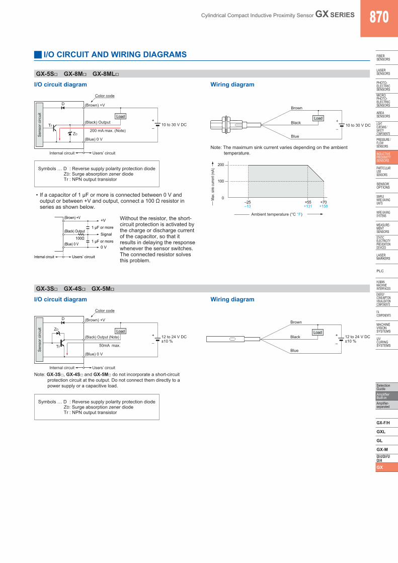
GX-5S□ GX-8M□ GX-8ML□
Wiring diagramI/O circuit diagram
Users’ circuitInternal circuit
D
Color code
200 mA max. (Note)
Sen
sor c
ircui
t
ZD
Tr
Load
(Blue) 0 V
(Black) Output
(Brown) +V
10 to 30 V DC+
–
Brown
Blue
Black Load
10 to 30 V DC+
–
Note: The maximum sink current varies depending on the ambient temperature.
200
100
0 –25–13
+55+131
+70+158
Ambient temperature (°C °F)M
ax. s
ink cu
rrent
(mA)Symbols … D : Reverse supply polarity protection diode
ZD: Surge absorption zener diodeTr : NPN output transistor
• If a capacitor of 1 µF or more is connected between 0 V and output or between +V and output, connect a 100 Ω resistor in series as shown below.
Users’ circuitInternal circuit
(Brown) +V
(Black) Output
(Blue) 0 V
+V
Signal
0 V
100Ω
1 μF or more
1 μF or more
Without the resistor, the short-circuit protection is activated by the charge or discharge current of the capacitor, so that it results in delaying the response whenever the sensor switches.The connected resistor solves this problem.
GX-3S□ GX-4S□ GX-5M□
Wiring diagramI/O circuit diagram
Tr
ZD
D
Color code
50mA max.
Sen
sor c
ircui
t
Load
(Blue) 0 V
(Black) Output (Note)
(Brown) +V
12 to 24 V DC±10 %
+
–
Users’ circuit Internal circuit
Brown
Blue
Black Load
12 to 24 V DC±10 %
+
–
Note: GX-3S□, GX-4S□ and GX-5M□ do not incorporate a short-circuit protection circuit at the output. Do not connect them directly to a power supply or a capacitive load.
Symbols … D : Reverse supply polarity protection diodeZD: Surge absorption zener diodeTr : NPN output transistor
871 Cylindrical Compact Inductive Proximity Sensor GX SERIES
Selection Guide
Amplifier Built-in
Amplifier-separated
GX-F/H
GXL
GL
GX-MGX-U/GX-FU/
GX-NGX
FIBERSENSORS
LASERSENSORS
PHOTO-ELECTRICSENSORS
MICROPHOTO-
ELECTRICSENSORS
AREASENSORS
LIGHTCURTAINS /
SAFETYCOMPONENTS
PRESSURE / FLOW
SENSORS
INDUCTIVEPROXIMITY
SENSORS
PARTICULARUSE
SENSORS
SENSOROPTIONS
SIMPLEWIRE-SAVING
UNITS
WIRE-SAVING SYSTEMS
MEASURE-MENT
SENSORSSTATIC
ELECTRICITYPREVENTION
DEVICES
LASERMARKERS
PLC
HUMAN MACHINE
INTERFACESENERGY
CONSUMPTION VISUALIZATION COMPONENTS
FA COMPONENTS
MACHINE VISION
SYSTEMS
UV CURING
SYSTEMS
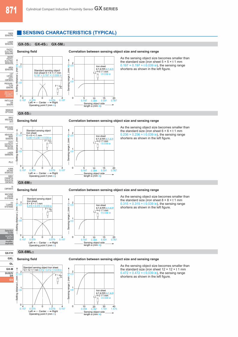
GX-3S□ GX-4S□ GX-5M□
Standard sensing objectIron sheet 5 × 5 × t 1 mm0.197 × 0.197 × t 0.039 in
L
40.157
40.157
20.079
20.079
00
Operating point ℓ (mm in)Left RightCenter
Set
ting
dist
ance
L (m
m in
)
10.039
20.079
ℓ
Sensing field Correlation between sensing object size and sensing range
t 1 mmt 0.039 in
Iron sheeta × a mm a × a in
L
50.197
0 100.394
150.591
200.787
Sensing object sidelength a (mm in)
Sen
sing
rang
e L
(mm
in)
10.039
20.079
As the sensing object size becomes smaller thanthe standard size (iron sheet 5 × 5 × t 1 mm0.197 × 0.197 × t 0.039 in), the sensing rangeshortens as shown in the left figure.
GX-5S□
Sensing field Correlation between sensing object size and sensing range
L
10.039
20.079
Set
ting
dist
ance
L (m
m in
)
40.157
40.157
20.079
0 20.079
Operating point ℓ (mm in)Left RightCenter
ℓ
Standard sensing objectIron sheet6 × 6 × t 1 mm0.236 × 0.236 × t 0.039 in
0
t 1 mmt 0.039 in
Iron sheeta × a mm a × a in
50.197
0 100.394
150.591
200.787
Sensing object sidelength a (mm in)
Sen
sing
rang
e L
(mm
in)
10.039
20.079
As the sensing object size becomes smaller thanthe standard size (iron sheet 6 × 6 × t 1 mm0.236 × 0.236 × t 0.039 in), the sensing rangeshortens as shown in the left figure.
GX-8M□
Sensing field Correlation between sensing object size and sensing range
L
10.039
20.079
Set
ting
dist
ance
L (m
m in
)
40.157
40.157
20.079
0 20.079
Operating point ℓ (mm in)Left RightCenter
ℓ
Standard sensing objectIron sheet8 × 8 × t 1 mm0.315 × 0.315 × t 0.039 in
0
t 1 mmt 0.039 in
Iron sheeta × a mm a × a in
L
50.197
0 100.394
150.591
200.787
Sensing object sidelength a (mm in)
Sen
sing
rang
e L
(mm
in)
10.039
20.079
As the sensing object size becomes smaller thanthe standard size (iron sheet 8 × 8 × t 1 mm0.315 × 0.315 × t 0.039 in), the sensing rangeshortens as shown in the left figure.
GX-8ML□
L
10.039
20.079
Set
ting
dist
ance
L (m
m in
)
40.157
40.157
20.079
0 20.079
Operating point ℓ (mm in)Left RightCenter
ℓ
Standard sensing object Iron sheet12 × 12 × t 1 mm 0.472 × 0.472 × t 0.039 in
0
Sensing field Correlation between sensing object size and sensing range
t 1 mmt 0.039 in
Iron sheeta × a mm a × a in
L
100.394
0 200.787
301.181
401.575
Sensing object sidelength a (mm in)
Sen
sing
rang
e L
(mm
in)
10.039
20.079
As the sensing object size becomes smaller thanthe standard size (iron sheet 12 × 12 × t 1 mm0.472 × 0.472 × t 0.039 in), the sensing rangeshortens as shown in the left figure.
SENSING CHARACTERISTICS (TYPICAL)
Cylindrical Compact Inductive Proximity Sensor GX SERIES 872
Selection GuideAmplifier Built-inAmplifier-separated
GX-F/H
GXL
GL
GX-MGX-U/GX-FU/GX-NGX
FIBERSENSORS
LASERSENSORS
PHOTO-ELECTRICSENSORSMICROPHOTO-ELECTRICSENSORS
AREASENSORS
LIGHTCURTAINS /SAFETYCOMPONENTSPRESSURE / FLOWSENSORS
INDUCTIVEPROXIMITYSENSORS
PARTICULARUSE SENSORS
SENSOROPTIONS
SIMPLEWIRE-SAVINGUNITS
WIRE-SAVING SYSTEMS
MEASURE-MENTSENSORSSTATIC ELECTRICITYPREVENTIONDEVICES
LASERMARKERS
PLC
HUMAN MACHINE INTERFACESENERGY CONSUMPTION VISUALIZATION COMPONENTS
FA COMPONENTS
MACHINE VISION SYSTEMS
UV CURING SYSTEMS
PRECAUTIONS FOR PROPER USE Refer to p.1485~ for general precautions.
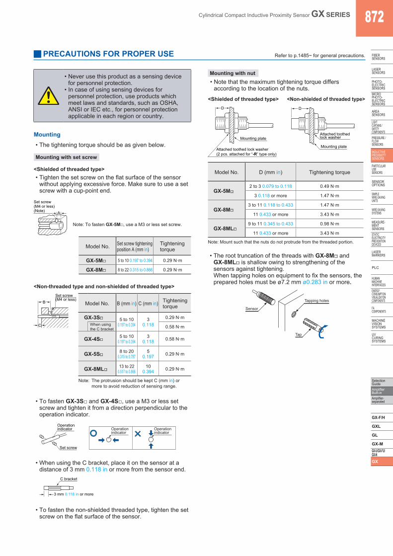
Mounting• The tightening torque should be as given below.
Mounting with set screw
• Tighten the set screw on the flat surface of the sensor without applying excessive force. Make sure to use a set screw with a cup-point end.
<Shielded of threaded type>
A
Set screw(M4 or less)(Note)
Note: To fasten GX-5M□, use a M3 or less set screw.
Model No. Set screw tighteningposition A (mm in)
Tightening torque
GX-5M□ 5 to 10 0.197 to 0.394 0.29 N·m
GX-8M□ 8 to 22 0.315 to 0.866 0.29 N·m
<Non-threaded type and non-shielded of threaded type>
Model No. B (mm in) C (mm in) Tightening torque
GX-3S□ 5 to 100.197 to 0.394
30.118
0.29 N·mWhen using the C bracket 0.58 N·m
GX-4S□ 5 to 100.197 to 0.394
30.118 0.58 N·m
GX-5S□ 8 to 200.315 to 0.787
50.197 0.29 N·m
GX-8ML□ 13 to 220.517 to 0.866
100.394 0.29 N·m
C
B
Set screw(M4 or less)
Note: The protrusion should be kept C (mm in) or more to avoid reduction of sensing range.
• To fasten GX-3S□ and GX-4S□, use a M3 or less set screw and tighten it from a direction perpendicular to the operation indicator.
Operationindicator
Set screw
Operationindicator
Operationindicator
• When using the C bracket, place it on the sensor at a distance of 3 mm 0.118 in or more from the sensor end.
C bracket
3 mm 0.118 in or more
• To fasten the non-shielded threaded type, tighten the set screw on the flat surface of the sensor.
Mounting with nut• Note that the maximum tightening torque differs
according to the location of the nuts.
<Shielded of threaded type> <Non-shielded of threaded type>D
Mounting plate
Attached toothed lock washer(2 pcs. attached for “-R” type only)
D
Mounting plate
Attached toothedlock washer
Model No. D (mm in) Tightening torque
GX-5M□2 to 3 0.079 to 0.118 0.49 N·m
3 0.118 or more 1.47 N·m
GX-8M□3 to 11 0.118 to 0.433 1.47 N·m
11 0.433 or more 3.43 N·m
GX-8ML□9 to 11 0.345 to 0.433 0.98 N·m
11 0.433 or more 3.43 N·m
Note: Mount such that the nuts do not protrude from the threaded portion.
• The root truncation of the threads with GX-8M□ and GX-8ML□ is shallow owing to strengthening of the sensors against tightening.When tapping holes on equipment to fix the sensors, the prepared holes must be ø7.2 mm ø0.283 in or more.
Sensor
Tapping holes
Tap
• Never use this product as a sensing device for personnel protection.
• In case of using sensing devices for personnel protection, use products which meet laws and standards, such as OSHA, ANSI or IEC etc., for personnel protection applicable in each region or country.
873 Cylindrical Compact Inductive Proximity Sensor GX SERIES
Selection Guide
Amplifier Built-in
Amplifier-separated
GX-F/H
GXL
GL
GX-MGX-U/GX-FU/
GX-NGX
FIBERSENSORS
LASERSENSORS
PHOTO-ELECTRICSENSORS
MICROPHOTO-
ELECTRICSENSORS
AREASENSORS
LIGHTCURTAINS /
SAFETYCOMPONENTS
PRESSURE / FLOW
SENSORS
INDUCTIVEPROXIMITY
SENSORS
PARTICULARUSE
SENSORS
SENSOROPTIONS
SIMPLEWIRE-SAVING
UNITS
WIRE-SAVING SYSTEMS
MEASURE-MENT
SENSORSSTATIC
ELECTRICITYPREVENTION
DEVICES
LASERMARKERS
PLC
HUMAN MACHINE
INTERFACESENERGY
CONSUMPTION VISUALIZATION COMPONENTS
FA COMPONENTS
MACHINE VISION
SYSTEMS
UV CURING
SYSTEMS
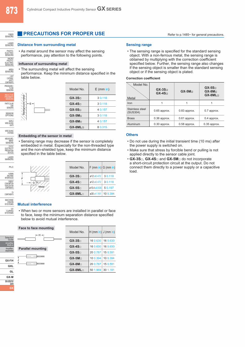
Distance from surrounding metal
PRECAUTIONS FOR PROPER USE Refer to p.1485~ for general precautions.
• As metal around the sensor may affect the sensing performance, pay attention to the following points.
Influence of surrounding metal• The surrounding metal will affect the sensing
performance. Keep the minimum distance specified in the table below.
Sensing range• The sensing range is specified for the standard sensing
object. With a non-ferrous metal, the sensing range is obtained by multiplying with the correction coefficient specified below. Further, the sensing range also changes if the sensing object is smaller than the standard sensing object or if the sensing object is plated.
E
Bac
kgro
und
met
al
Model No. E (mm in)
GX-3S□ 3 0.118
GX-4S□ 3 0.118
GX-5S□ 4 0.157
GX-5M□ 3 0.118
GX-8M□ 4 0.157
GX-8ML□ 8 0.315
Embedding of the sensor in metal• Sensing range may decrease if the sensor is completely
embedded in metal. Especially for the non-threaded type and the non-shielded type, keep the minimum distance specified in the table below.
F
GMetal
Model No. F (mm in) G (mm in)
GX-3S□ ø12 ø0.472 3 0.118
GX-4S□ ø12 ø0.472 3 0.118
GX-5S□ ø15.4 ø0.606 5 0.197
GX-8ML□ ø30 ø1.181 10 0.394
Mutual interference• When two or more sensors are installed in parallel or face
to face, keep the minimum separation distance specified below to avoid mutual interference.
Face to face mounting
Parallel mounting
H
J
Model No. H (mm in) J (mm in)
GX-3S□ 16 0.630 16 0.630
GX-4S□ 16 0.630 16 0.630
GX-5S□ 20 0.787 15 0.591
GX-5M□ 10 0.394 10 0.394
GX-8M□ 20 0.787 15 0.591
GX-8ML□ 50 1.969 30 1.181
Correction coefficient
Others
• Do not use during the initial transient time (10 ms) after the power supply is switched on.
• Make sure that stress by forcible bend or pulling is not applied directly to the sensor cable joint.
• GX-3S□, GX-4S□ and GX-5M□ do not incorporate a short-circuit protection circuit at the output. Do not connect them directly to a power supply or a capacitive load.
Model No.GX-3S□GX-4S□ GX-5M□
GX-5S□GX-8M□GX-8ML□
MetalIron 1 1 1
Stainless steel(SUS304) 0.65 approx. 0.83 approx. 0.7 approx.
Brass 0.36 approx. 0.61 approx. 0.4 approx.
Aluminum 0.30 approx. 0.58 approx. 0.35 approx.
Cylindrical Compact Inductive Proximity Sensor GX SERIES 874
Selection GuideAmplifier Built-inAmplifier-separated
GX-F/H
GXL
GL
GX-MGX-U/GX-FU/GX-NGX
FIBERSENSORS
LASERSENSORS
PHOTO-ELECTRICSENSORSMICROPHOTO-ELECTRICSENSORS
AREASENSORS
LIGHTCURTAINS /SAFETYCOMPONENTSPRESSURE / FLOWSENSORS
INDUCTIVEPROXIMITYSENSORS
PARTICULARUSE SENSORS
SENSOROPTIONS
SIMPLEWIRE-SAVINGUNITS
WIRE-SAVING SYSTEMS
MEASURE-MENTSENSORSSTATIC ELECTRICITYPREVENTIONDEVICES
LASERMARKERS
PLC
HUMAN MACHINE INTERFACESENERGY CONSUMPTION VISUALIZATION COMPONENTS
FA COMPONENTS
MACHINE VISION SYSTEMS
UV CURING SYSTEMS
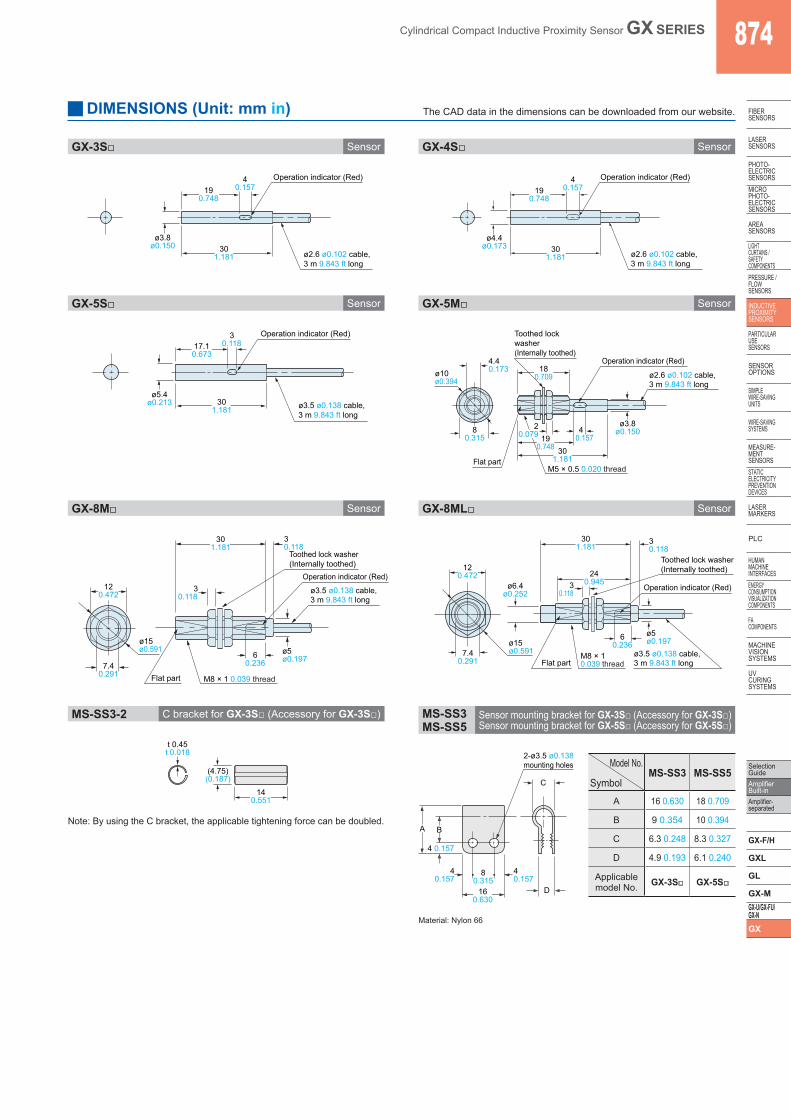
SensorGX-3S□
SensorGX-5S□
SensorGX-4S□
SensorGX-5M□
190.748
301.181
40.157
ø2.6 ø0.102 cable,3 m 9.843 ft long
ø3.8ø0.150
Operation indicator (Red)
190.748
301.181
40.157
ø2.6 ø0.102 cable,3 m 9.843 ft long
ø4.4ø0.173
Operation indicator (Red)
17.10.673
301.181
30.118
ø3.5 ø0.138 cable,3 m 9.843 ft long
ø5.4ø0.213
Operation indicator (Red)
4.40.173
ø2.6 ø0.102 cable,3 m 9.843 ft long
ø3.8ø0.150
ø10ø0.394
301.181
190.748
80.315
180.709
40.157
Flat part
20.079
Operation indicator (Red)
M5 × 0.5 0.020 thread
Toothed lockwasher(Internally toothed)
SensorGX-8M□ SensorGX-8ML□
ø3.5 ø0.138 cable,3 m 9.843 ft long
ø5ø0.197
ø15ø0.591
60.2367.4
0.291
120.472
301.181
Flat part
30.118
30.118
Operation indicator (Red)
M8 × 1 0.039 thread
Toothed lock washer(Internally toothed)
ø3.5 ø0.138 cable,3 m 9.843 ft long
ø5ø0.197
ø6.4ø0.252
ø15ø0.591
60.236
7.40.291
120.472
301.181
240.945
Flat part
30.118
30.118
Operation indicator (Red)
M8 × 10.039 thread
Toothed lock washer(Internally toothed)
C bracket for GX-3S□ (Accessory for GX-3S□)MS-SS3-2 Sensor mounting bracket for GX-3S□ (Accessory for GX-3S□)Sensor mounting bracket for GX-5S□ (Accessory for GX-5S□)
MS-SS3MS-SS5
2-ø3.5 ø0.138mounting holes
40.157
40.157
4 0.157
A B
D
C
80.315
160.630
t 0.45t 0.018
(4.75)(0.187)
140.551
Note: By using the C bracket, the applicable tightening force can be doubled.
Material: Nylon 66
Model No.
SymbolMS-SS3 MS-SS5
A 16 0.630 18 0.709
B 9 0.354 10 0.394
C 6.3 0.248 8.3 0.327
D 4.9 0.193 6.1 0.240
Applicablemodel No. GX-3S□ GX-5S□
DIMENSIONS (Unit: mm in) The CAD data in the dimensions can be downloaded from our website.