Embed Size (px)
Citation preview
BKTContrast Sensor
PhotoelectricSensors
2.2.54
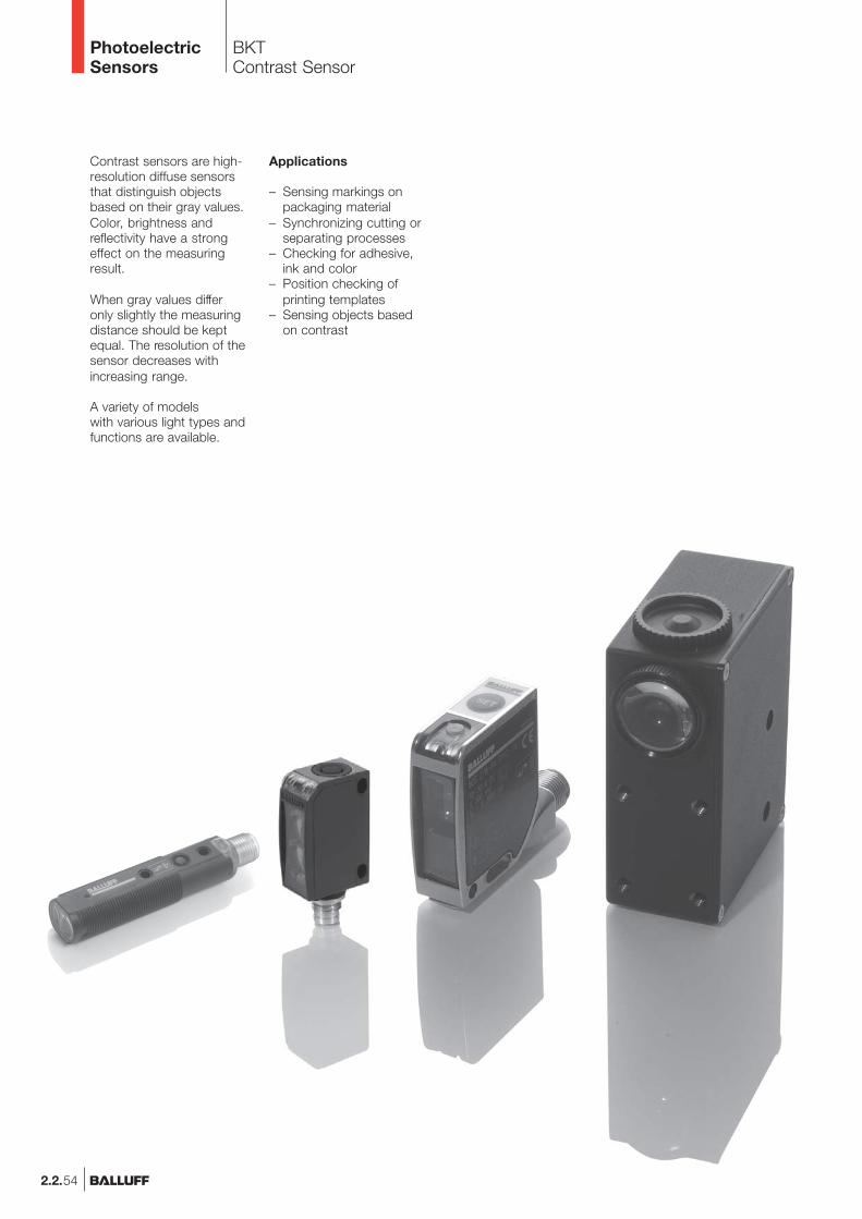
Contrast sensors are high-resolution diffuse sensorsthat distinguish objectsbased on their gray values.Color, brightness andreflectivity have a strongeffect on the measuringresult.
When gray values differonly slightly the measuringdistance should be keptequal. The resolution of thesensor decreases withincreasing range.
A variety of modelswith various light types andfunctions are available.
Applications
– Sensing markings onpackaging material
– Synchronizing cutting orseparating processes
– Checking for adhesive,ink and color
– Position checking ofprinting templates
– Sensing objects basedon contrast
BKTContrast SensorProduct Overview
2.2.55
2.2
Photoelectricsensorsaccessoriespage 2.3.2 ...
2.3
PhotoelectricSensors
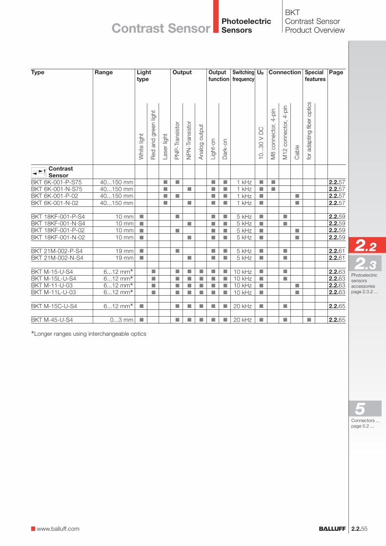
Type
ContrastSensor
BKT 6K-001-P-S75BKT 6K-001-N-S75BKT 6K-001-P-02BKT 6K-001-N-02
BKT 18KF-001-P-S4BKT 18KF-001-N-S4BKT 18KF-001-P-02BKT 18KF-001-N-02
BKT 21M-002-P-S4BKT 21M-002-N-S4
BKT M-15-U-S4BKT M-15L-U-S4BKT M-11-U-03BKT M-11L-U-03
BKT M-15C-U-S4
BKT M-45-U-S4
OutputLighttype
Range
40...150 mm40...150 mm40...150 mm40...150 mm
10 mm10 mm10 mm10 mm
19 mm19 mm
6...12 mm*6...12 mm*6...12 mm*6...12 mm*6...12 mm*
0...3 mm
Connection
1 kHz1 kHz1 kHz1 kHz
5 kHz5 kHz5 kHz5 kHz
5 kHz5 kHz
10 kHz10 kHz10 kHz10 kHz
20 kHz
20 kHz
Outputfunction
Page
2.2.572.2.572.2.572.2.57
2.2.592.2.592.2.592.2.59
2.2.612.2.61
2.2.632.2.632.2.632.2.63
2.2.65
2.2.65
Whi
te li
ght
Red
and
gre
en li
ght
M8
conn
ecto
r, 4-
pin
M12
con
nect
or, 4
-pin
10...
30 V
DC
NP
N-T
rans
isto
r
PN
P-T
rans
isto
r
Ligh
t-on
Dar
k-on
UBSwitchingfrequency
Cab
le
Ana
log
outp
ut
Lase
r lig
ht
Contrast Sensor
Specialfeatures
for a
dapt
ing
fiber
opt
ics
www.balluff.com
*Longer ranges using interchangeable optics
Connectors ...page 5.2 ...
5
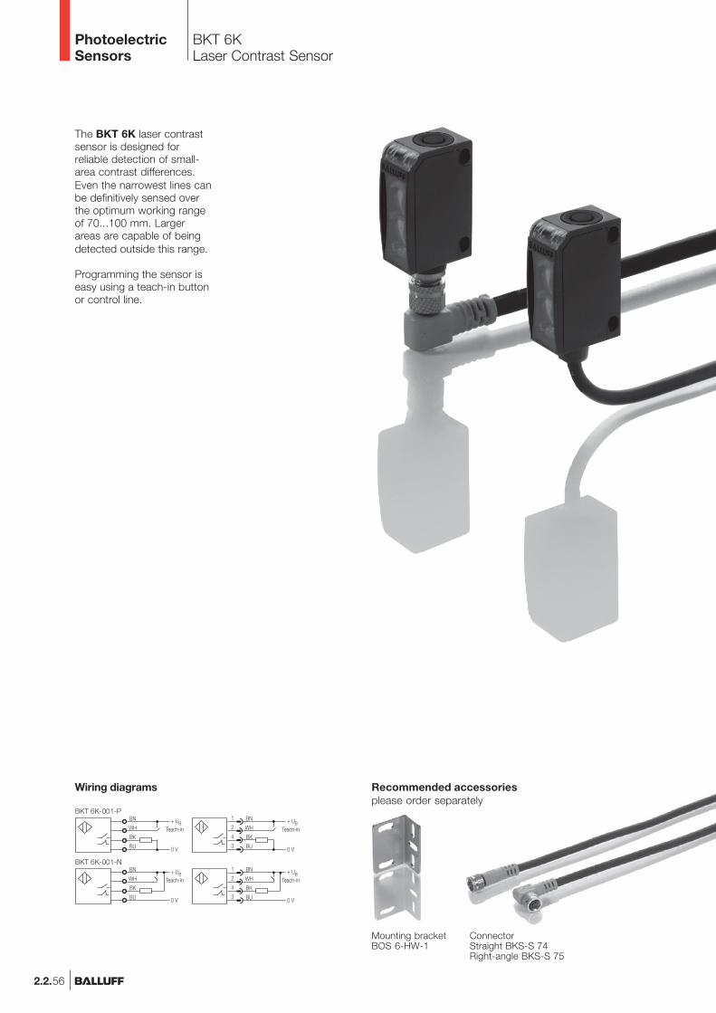
BKT 6KLaser Contrast Sensor
PhotoelectricSensors
2.2.56
The BKT 6K laser contrastsensor is designed forreliable detection of small-area contrast differences.Even the narrowest lines canbe definitively sensed overthe optimum working rangeof 70...100 mm. Largerareas are capable of beingdetected outside this range.
Programming the sensor iseasy using a teach-in buttonor control line.
ConnectorStraight BKS-S 74Right-angle BKS-S 75
Mounting bracketBOS 6-HW-1
Wiring diagrams Recommended accessoriesplease order separately
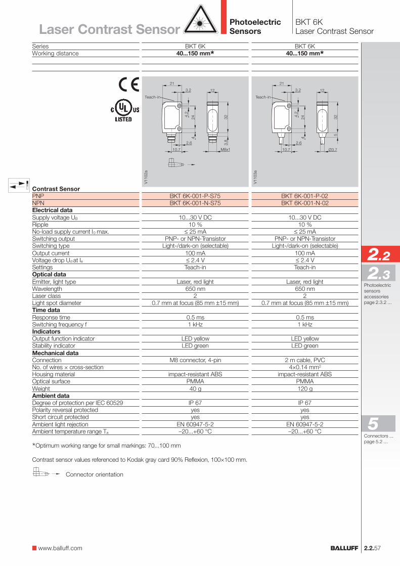
BKT 6KLaser Contrast Sensor
2.2.57
2.2
Photoelectricsensorsaccessoriespage 2.3.2 ...
2.3
SeriesWorking distance
Contrast SensorPNPNPNElectrical dataSupply voltage UB
RippleNo-load supply current I0 max.Switching outputSwitching typeOutput currentVoltage drop Ud at IeSettingsOptical dataEmitter, light typeWavelengthLaser classLight spot diameterTime dataResponse timeSwitching frequency fIndicatorsOutput function indicatorStability indicatorMechanical dataConnectionNo. of wires × cross-sectionHousing materialOptical surfaceWeightAmbient dataDegree of protection per IEC 60529Polarity reversal protectedShort circuit protectedAmbient light rejectionAmbient temperature range Ta
Connector orientation
PhotoelectricSensors
BKT 6K40...150 mm*
BKT 6K-001-P-S75BKT 6K-001-N-S75
10...30 V DC10 %
≤ 25 mAPNP- or NPN-Transistor
Light-/dark-on (selectable)100 mA≤ 2.4 VTeach-in
Laser, red light650 nm
20.7 mm at focus (85 mm ±15 mm)
0.5 ms1 kHz
LED yellowLED green
M8 connector, 4-pin
impact-resistant ABSPMMA40 g
IP 67yesyes
EN 60947-5-2–20...+60 °C
BKT 6K40...150 mm*
BKT 6K-001-P-02BKT 6K-001-N-02
10...30 V DC10 %
≤ 25 mAPNP- or NPN-Transistor
Light-/dark-on (selectable)100 mA≤ 2.4 VTeach-in
Laser, red light650 nm
20.7 mm at focus (85 mm ±15 mm)
0.5 ms1 kHz
LED yellowLED green
2 m cable, PVC4×0.14 mm2
impact-resistant ABSPMMA120 g
IP 67yesyes
EN 60947-5-2–20...+60 °C
*Optimum working range for small markings: 70...100 mm
Contrast sensor values referenced to Kodak gray card 90% Reflexion, 100×100 mm.
Laser Contrast Sensor
www.balluff.com
Teach-in Teach-in
Connectors ...page 5.2 ...
5
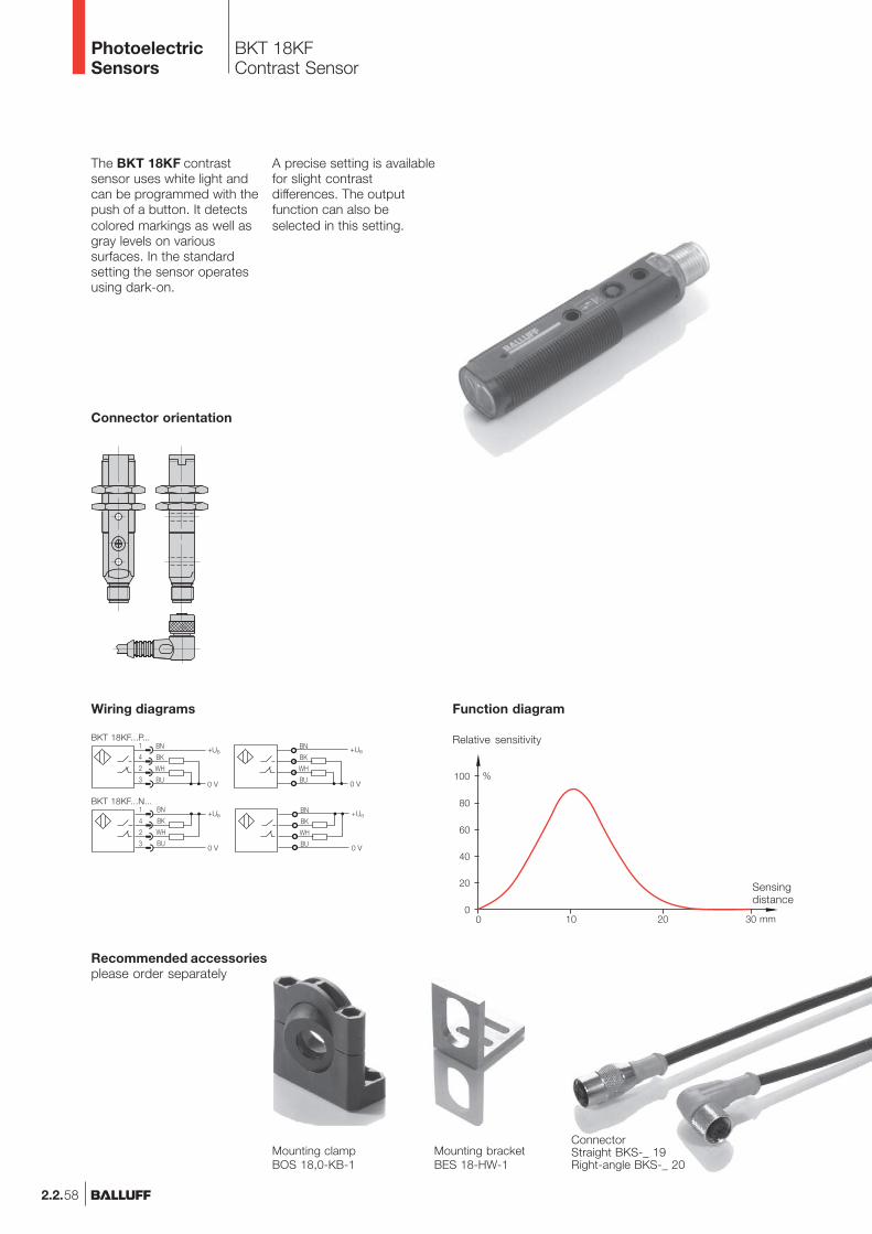
BKT 18KFContrast Sensor
PhotoelectricSensors
2.2.58
Recommended accessoriesplease order separately
Mounting clampBOS 18,0-KB-1
Mounting bracketBES 18-HW-1
ConnectorStraight BKS-_ 19Right-angle BKS-_ 20
The BKT 18KF contrastsensor uses white light andcan be programmed with thepush of a button. It detectscolored markings as well asgray levels on varioussurfaces. In the standardsetting the sensor operatesusing dark-on.
A precise setting is availablefor slight contrastdifferences. The outputfunction can also beselected in this setting.
Function diagram
BN
BK
WH
BU
+UB
0 V
BN
BK
WH
BU
+UB
0 V
Wiring diagrams
BKT 18KF...P...
BKT 18KF...N...
Relative sensitivity
Sensingdistance
Connector orientation
BKT 18KFContrast Sensor
2.2.59
2.2
Photoelectricsensorsaccessoriespage 2.3.2 ...
2.3
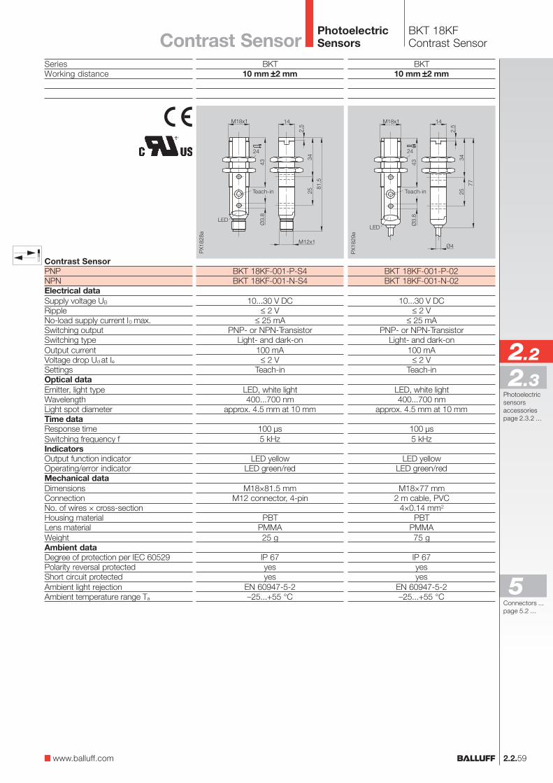
SeriesWorking distance
Contrast SensorPNPNPNElectrical dataSupply voltage UB
RippleNo-load supply current I0 max.Switching outputSwitching typeOutput currentVoltage drop Ud at IeSettingsOptical dataEmitter, light typeWavelengthLight spot diameterTime dataResponse timeSwitching frequency fIndicatorsOutput function indicatorOperating/error indicatorMechanical dataDimensionsConnectionNo. of wires × cross-sectionHousing materialLens materialWeightAmbient dataDegree of protection per IEC 60529Polarity reversal protectedShort circuit protectedAmbient light rejectionAmbient temperature range Ta
PhotoelectricSensors
BKT10 mm ±±±±±2 mm
BKT 18KF-001-P-S4BKT 18KF-001-N-S4
10...30 V DC≤ 2 V
≤ 25 mAPNP- or NPN-Transistor
Light- and dark-on100 mA
≤ 2 VTeach-in
LED, white light400...700 nm
approx. 4.5 mm at 10 mm
100 µs5 kHz
LED yellowLED green/red
M18×81.5 mmM12 connector, 4-pin
PBTPMMA25 g
IP 67yesyes
EN 60947-5-2–25...+55 °C
BKT10 mm ±±±±±2 mm
BKT 18KF-001-P-02BKT 18KF-001-N-02
10...30 V DC≤ 2 V
≤ 25 mAPNP- or NPN-Transistor
Light- and dark-on100 mA
≤ 2 VTeach-in
LED, white light400...700 nm
approx. 4.5 mm at 10 mm
100 µs5 kHz
LED yellowLED green/red
M18×77 mm2 m cable, PVC
4×0.14 mm2
PBTPMMA75 g
IP 67yesyes
EN 60947-5-2–25...+55 °C
Contrast Sensor
www.balluff.com
Teach-in Teach-in
Connectors ...page 5.2 ...
5

BKT 21MContrast Sensor
PhotoelectricSensors
2.2.60
The BKT 21M contrastsensor uses white light andcan be programmed with thepush of a button. It detectscolored markings as well asgray levels on varioussurfaces. In its standardsetting the sensor is dark-switching (markings with lesslight intensity are detectedas the background).
Wiring diagrams Function diagram
ConnectorStraight BKS-_ 19Right-angle BKS-_ 20
Recommended accessoriesplease order separately
Mounting bracketBOS 21-HW-1
Mounting clampBOS 21-KH-1
Mounting clampBOS 21-KH-2
Mounting bracketBOS 21-HW-2
BKT 21M...P..
BKT 21M...N..
Relative sensitivity
Sensingdistance
A precise setting isavailable for slight contrastdifferences. The outputfunction can also beselected in this setting.
Indicators and operating elements
1 Output function indicator (yellow)2 Operating/error indicator (green/red)3 SET key
1 2 3
BKT 21MContrast Sensor
2.2.61
2.2
Photoelectricsensorsaccessoriespage 2.3.2 ...
2.3
PhotoelectricSensors
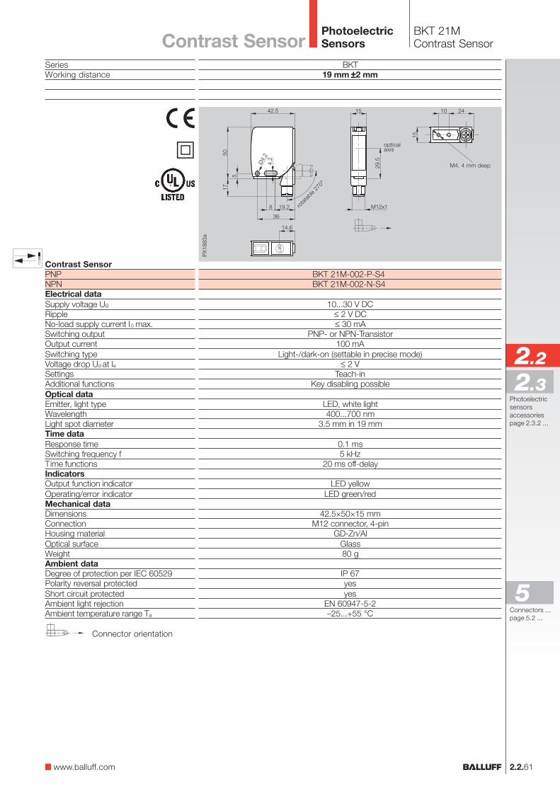
SeriesWorking distance
Contrast SensorPNPNPNElectrical dataSupply voltage UB
RippleNo-load supply current I0 max.Switching outputOutput currentSwitching typeVoltage drop Ud at IeSettingsAdditional functionsOptical dataEmitter, light typeWavelengthLight spot diameterTime dataResponse timeSwitching frequency fTime functionsIndicatorsOutput function indicatorOperating/error indicatorMechanical dataDimensionsConnectionHousing materialOptical surfaceWeightAmbient dataDegree of protection per IEC 60529Polarity reversal protectedShort circuit protectedAmbient light rejectionAmbient temperature range Ta
BKT19 mm ±±±±±2 mm
BKT 21M-002-P-S4BKT 21M-002-N-S4
10...30 V DC≤ 2 V DC≤ 30 mA
PNP- or NPN-Transistor100 mA
Light-/dark-on (settable in precise mode)≤ 2 V
Teach-inKey disabling possible
LED, white light400...700 nm
3.5 mm in 19 mm
0.1 ms5 kHz
20 ms off-delay
LED yellowLED green/red
42.5×50×15 mmM12 connector, 4-pin
GD-Zn/AlGlass80 g
IP 67yesyes
EN 60947-5-2–25...+55 °C
Connector orientation
rota
table
270
°
M4, 4 mm deep
opticalaxis
Contrast Sensor
�
www.balluff.com
Connectors ...page 5.2 ...
5
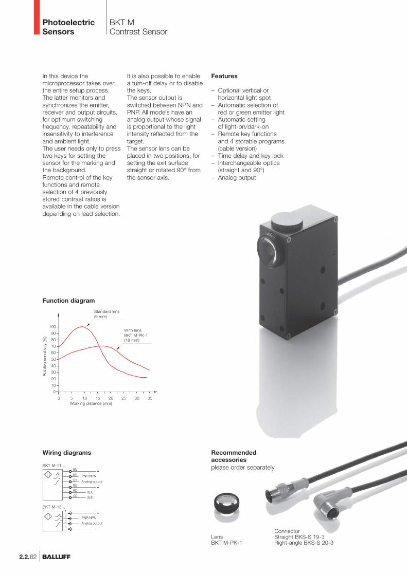
In this device themicroprocessor takes overthe entire setup process.The latter monitors andsynchronizes the emitter,receiver and output circuits,for optimum switchingfrequency, repeatability andinsensitivity to interferenceand ambient light.The user needs only to presstwo keys for setting thesensor for the marking andthe background.Remote control of the keyfunctions and remoteselection of 4 previouslystored contrast ratios isavailable in the cable versiondepending on lead selection.
Features
– Optional vertical orhorizontal light spot
– Automatic selection ofred or green emitter light
– Automatic settingof light-on/dark-on
– Remote key functionsand 4 storable programs(cable version)
– Time delay and key lock– Interchangeable optics
(straight and 90°)– Analog output
It is also possible to enablea turn-off delay or to disablethe keys.The sensor output isswitched between NPN andPNP. All models have ananalog output whose signalis proportional to the lightintensity reflected from thetarget.The sensor lens can beplaced in two positions, forsetting the exit surfacestraight or rotated 90° fromthe sensor axis.
BKT MContrast Sensor
PhotoelectricSensors
2.2.62
Recommendedaccessoriesplease order separately
LensBKT M-PK-1
Analog output
Analog output
Wiring diagrams
PNP/NPN
PNP/NPN
BKT M-11...
BKT M-15...
ConnectorStraight BKS-S 19-3Right-angle BKS-S 20-3
Function diagram
Working distance (mm)
Rel
ativ
e se
nsiti
vity
(%)
Standard lens(9 mm)
With lensBKT M-PK-1(18 mm)
BKT MContrast Sensor
2.2.63
2.2
Photoelectricsensorsaccessoriespage 2.3.2 ...
2.3
PhotoelectricSensors
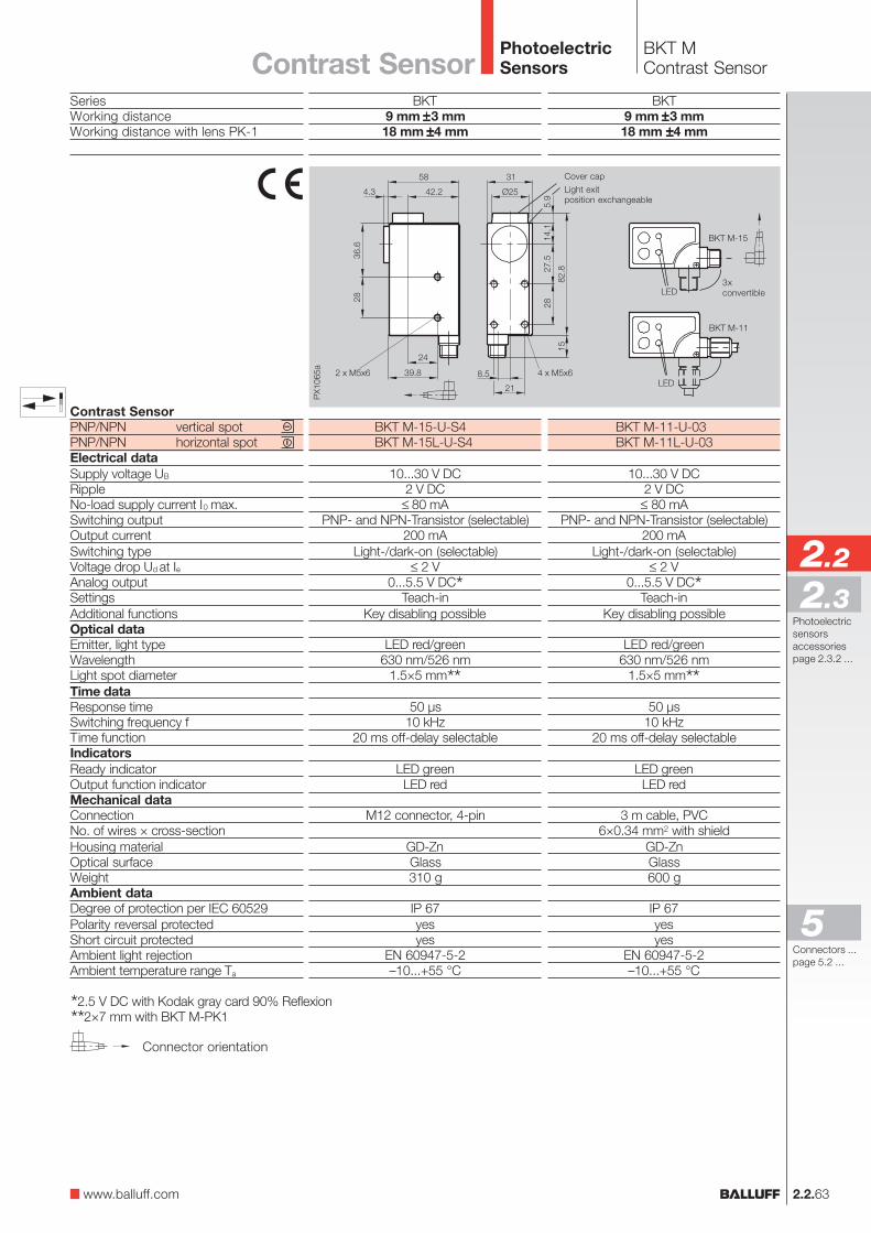
SeriesWorking distanceWorking distance with lens PK-1
Contrast SensorPNP/NPN vertical spotPNP/NPN horizontal spotElectrical dataSupply voltage UB
RippleNo-load supply current I0 max.Switching outputOutput currentSwitching typeVoltage drop Ud at IeAnalog outputSettingsAdditional functionsOptical dataEmitter, light typeWavelengthLight spot diameterTime dataResponse timeSwitching frequency fTime functionIndicatorsReady indicatorOutput function indicatorMechanical dataConnectionNo. of wires × cross-sectionHousing materialOptical surfaceWeightAmbient dataDegree of protection per IEC 60529Polarity reversal protectedShort circuit protectedAmbient light rejectionAmbient temperature range Ta
BKT9 mm ±±±±±3 mm18 mm ±±±±±4 mm
BKT M-15-U-S4BKT M-15L-U-S4
10...30 V DC2 V DC
≤ 80 mAPNP- and NPN-Transistor (selectable)
200 mALight-/dark-on (selectable)
≤ 2 V0...5.5 V DC*
Teach-inKey disabling possible
LED red/green630 nm/526 nm
1.5×5 mm**50 µs
10 kHz20 ms off-delay selectable
LED greenLED red
M12 connector, 4-pin
GD-ZnGlass310 g
IP 67yesyes
EN 60947-5-2–10...+55 °C
Cover cap
Light exitposition exchangeable
Connector orientation
3xconvertible
*2.5 V DC with Kodak gray card 90% Reflexion**2×7 mm with BKT M-PK1
BKT9 mm ±±±±±3 mm18 mm ±±±±±4 mm
BKT M-11-U-03BKT M-11L-U-03
10...30 V DC2 V DC
≤ 80 mAPNP- and NPN-Transistor (selectable)
200 mALight-/dark-on (selectable)
≤ 2 V0...5.5 V DC*
Teach-inKey disabling possible
LED red/green630 nm/526 nm
1.5×5 mm**50 µs
10 kHz20 ms off-delay selectable
LED greenLED red
3 m cable, PVC6×0.34 mm2 with shield
GD-ZnGlass600 g
IP 67yesyes
EN 60947-5-2–10...+55 °C
Contrast Sensor
www.balluff.com
Connectors ...page 5.2 ...
5
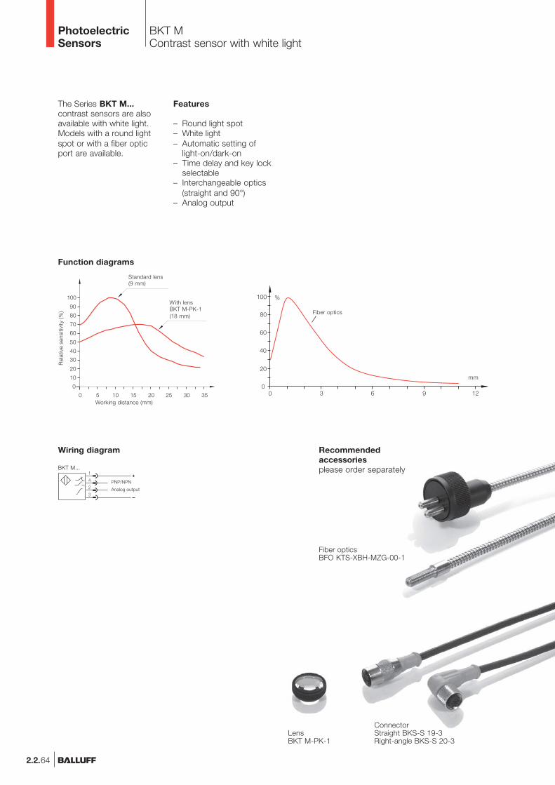
The Series BKT M...contrast sensors are alsoavailable with white light.Models with a round lightspot or with a fiber opticport are available.
Features
– Round light spot– White light– Automatic setting of
light-on/dark-on– Time delay and key lock
selectable– Interchangeable optics
(straight and 90°)– Analog output
BKT MContrast sensor with white light
PhotoelectricSensors
2.2.64
Recommendedaccessoriesplease order separately
LensBKT M-PK-1
Analog output
Wiring diagram
PNP/NPN
BKT M...
Function diagrams
Working distance (mm)
Rel
ativ
e se
nsiti
vity
(%)
Standard lens(9 mm)
With lensBKT M-PK-1(18 mm)
Fiber opticsBFO KTS-XBH-MZG-00-1
ConnectorStraight BKS-S 19-3Right-angle BKS-S 20-3
Fiber optics
BKT MContrast Sensorwith white light
2.2.65
2.2
Photoelectricsensorsaccessoriespage 2.3.2 ...
2.3
PhotoelectricSensors
Contrast Sensorwith white light
www.balluff.com
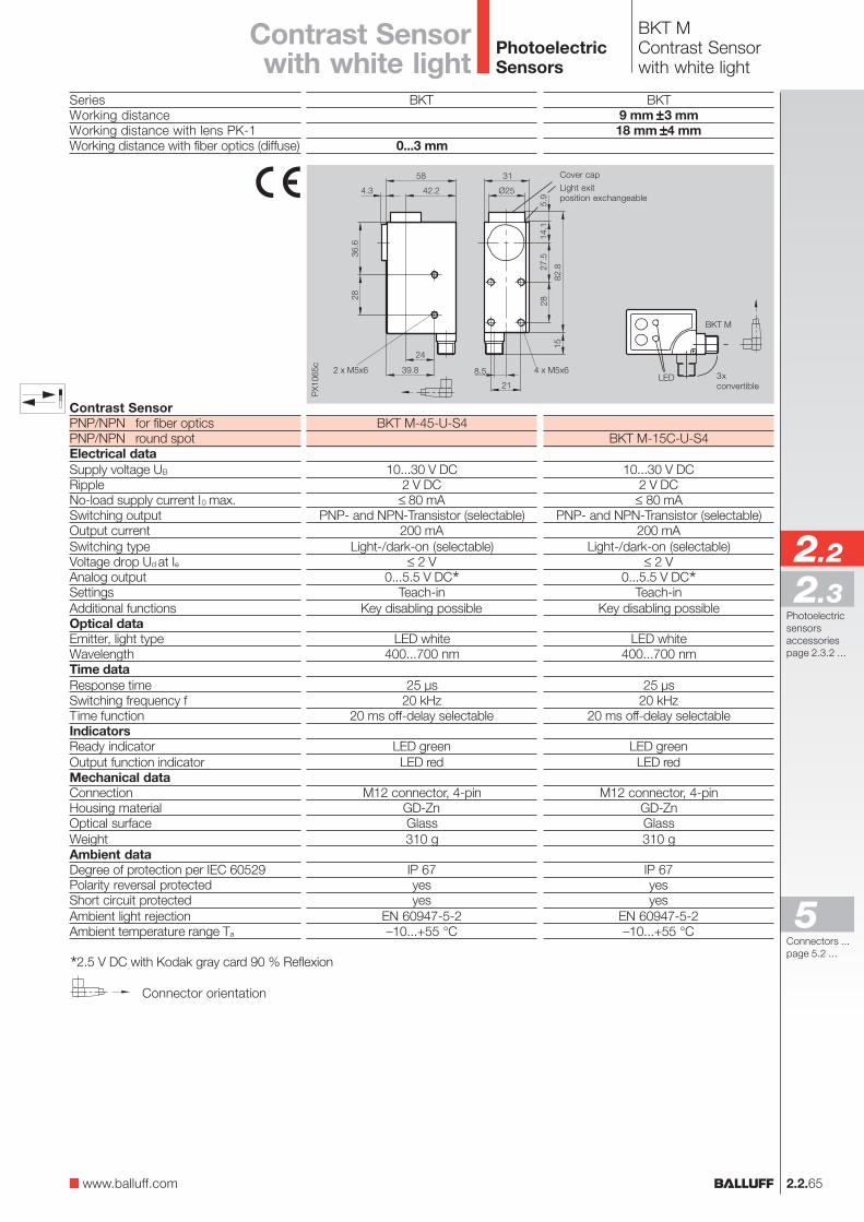
Cover cap
Light exitposition exchangeable
3xconvertible
SeriesWorking distanceWorking distance with lens PK-1Working distance with fiber optics (diffuse)
Contrast SensorPNP/NPN for fiber opticsPNP/NPN round spotElectrical dataSupply voltage UB
RippleNo-load supply current I0 max.Switching outputOutput currentSwitching typeVoltage drop Ud at IeAnalog outputSettingsAdditional functionsOptical dataEmitter, light typeWavelengthTime dataResponse timeSwitching frequency fTime functionIndicatorsReady indicatorOutput function indicatorMechanical dataConnectionHousing materialOptical surfaceWeightAmbient dataDegree of protection per IEC 60529Polarity reversal protectedShort circuit protectedAmbient light rejectionAmbient temperature range Ta
BKT
0...3 mm
BKT M-45-U-S4
10...30 V DC2 V DC
≤ 80 mAPNP- and NPN-Transistor (selectable)
200 mALight-/dark-on (selectable)
≤ 2 V0...5.5 V DC*
Teach-inKey disabling possible
LED white400...700 nm
25 µs20 kHz
20 ms off-delay selectable
LED greenLED red
M12 connector, 4-pinGD-ZnGlass310 g
IP 67yesyes
EN 60947-5-2–10...+55 °C
Connector orientation
*2.5 V DC with Kodak gray card 90 % Reflexion
BKT9 mm ±±±±±3 mm18 mm ±±±±±4 mm
BKT M-15C-U-S4
10...30 V DC2 V DC
≤ 80 mAPNP- and NPN-Transistor (selectable)
200 mALight-/dark-on (selectable)
≤ 2 V0...5.5 V DC*
Teach-inKey disabling possible
LED white400...700 nm
25 µs20 kHz
20 ms off-delay selectable
LED greenLED red
M12 connector, 4-pinGD-ZnGlass310 g
IP 67yesyes
EN 60947-5-2–10...+55 °C
Connectors ...page 5.2 ...
5