Embed Size (px)
Citation preview
Cyclone: A Laser Scanner For Mobile Robot Navigation
Sanjiv Singh and Jay West
CMU-RI-TR-91-18
The Robotics Institute Carnegie MelIon University
Pittsburgh, Pennsylvania 15213
September 1991
Copyright Q 1991 Carnegie Mellon University

Table of Contents
1. 2. 3 3.1 3.2 3.2.1 3.3 3.4 3.5 3.6 3.6.1 3.6.2 4. 4.1 4.2 5 .
Introduction Background & Specification Scanner Design
Configuration The Rangefinder
Interfacing with the Rangefinder Scanner Enclosure Power and Communication Enclosure Motion Control Electronic Design
The Interface Circuit The Data Buffer Cicruit
Applications Obstacle Detection Use on the LE (360 radial scan)
Discussion
1 2 5 5 6 8 8
10 11 12 12 12 15 15 16 18

List of Figures
1 2 3 4 5 6 7 8 9 10 11 12 13
Cyclone Configuration of the system The rangefinder Operation of rangefinding device Scanner enclosure Tower motion sensors Power and Communication Enclosure Communication between the Interface Circuit and Data Buffer Circuit Communication with the host computer Cyclone mounted on the front bumper of NavLab The "pendulum" mount for 3-D scanning Cyclone mounted on the Locomotion Emulator Sample data obtained from the Cyclone
1 6 7 7 9
10 11 13 14 15 16 16 17
Abstract
Researchers at Carnegie Mellon’s Field Robotics Center have designed and implemented a scanning laser rangefinder. The device uses a commercially available time-of-flight ranging instrument that is capable of making up to 7200 measurements per second. The laser beam is reflected by a rotating mirror, producing up to a 360 degree view. Mounted on a robot vehicle, the scanner can be used to detect obstacles in the vehicle’s path or to locate the robot on a map. This report discusses the motivation, design, and some applications of the scanner.

1. Introduction
Range information is essential for robot vehicle navigation. Even if a robot‘s path has been preplanned, in a realistic scenario, the robot must perceive obstructions that might inter- fere with its travel. We have designed and implemented a scanning rangefinder, Cyclone, that enables a robot vehicle to determine the three dimensional shape of its environment with high accuracy. The device, built over a period of 18 months starting in mid-1987, has since been used in various configurations for obstacle detection, collision avoidance and more recently for position estimation. Obstacle detection is concerned with locating obstacles in a vehicle’s future path so that the vehicle can decelerate from a high speed to a stop before it collides with the obstacle[ll. Collision avoidance involves navigating the vehicle around the detected obstacles to converge with the prespecified path[2]. Although the device was originally designed for the afore mentioned applications, more recently it has been successfully used for position estimation, which is the determination of vehicle location on a map using onboard sensors[3].
At the heart of Cyclone is a time-of-flight ranging device that can make range measure- ments at up to 7200 hz. In conjunction with a rotating mirror arranged in a periscope like configuration, the system is able to produce radial range scans. The scanner is shown in Figure 1.
Figure 1: Cyclone In this report we discuss themotivation for such a device, its design and some of its appli- cations. In section 2, we discuss relevant background work and resulting specifications for the scanner. In section 3 we discuss the design of the scanner. Section 4 briefly discusses the applications for which the Cyclone has been used so far. Section 5 discusses some of the salient development issues.
1
2. Background & Specification
Having chosen ranging as the means to accomplish obstacle detection and collision avoidance, it remained to choose from the many methods possible to obtain range infor- mation. In this section we discuss some of these methods and outline the resulting speci- fications for the scanner.
Several surveys of ranging methods exist in the literature 1421 and we will only briefly review some of the common methods of obtaining range. Range sensing methods can be classified as either passive or active. Passive methods derive range information by using ambient energy, typically by analyzing video images of a scene. A commonly used method is called ”computational stereo”. Either images from multiple cameras at fixed locations (binocular/trinodar stereo) or image sequences from a moving camera (motion stereo) are used. Given a precise difference between camera locations and a means of establishing correspondence between features in the various images, i t is possible to obtain range estimates from simple geometric relationships[6,71. Since compu- tational stereo methods rely on finding a correspondence between features in separate images, the computational effort for such methods depends on the scenes being imaged; in the worst case, a single range image may take minutes to compute. It may not be possible to obtain any range information if the scene has sparse features and hence impos- sible to obtain a unique correspondence between features in the various images. Other passive methods have been proposed, for example depth from focusing[8] and from anal- ysis of shading191 of a video image. In general passive methods are vulnerable to poor illumination conditions and have worked best in structured laboratory type settings.
In contrast, active methods project energy onto the scene and are not constrained by ambient lighting conditions. Active methods are further of several types. The simplest type uses triangulation of a projected light beam, much the way that computational stereo does. The correspondence problem is avoided because the projection of the beam can be easily found in the image. The distortion produced by the effect of uneven terrain on structured light can be used to produce three dimensional maps. The feasibility of several devices [lo, 11,121 using such a principle has been demonstrated over a range of 1-2 m.
A second method transmits laser energy into the scene and measures the phase shift of the returning signal as compared to that of the outgoing signal. The phase shift can be related to distance within the ambiguity interval of one wavelength. That is, such a sensor cannot distinguish between distance E and 1 +E, where I is the interval of ambiguity corre- sponding to the distance at which the returned signal is exactly in phase with the outgoing wave. Several devices have been built using this method, and to date this remains the most commonly used method of laser ranging 1131.
A third method measures time of flight that pulses of energy take to travel from the sensor to the scene and back.Time-of-flight devices that use ultrasonic, millimeter radar, and laser wavelength waves have been built. Ultrasonic ranging devices can provide reason- able range estimates at small distances (approximately 10- 30 an) and coarse estimates at distances of 2-5 m. The problem with sonar ranging is that most natural objects appear
2
specular to ultrasonic energy and it is possible to get inter-reflections from corners very easily. That is, most surfaces reflect ultrasonic waves such that the angle of reflection (with respect to the surface normal) is equal to the angle of incidence. Very little energy is returned in the direction of the incident beam and quite often the returned signal measured is reflected off a second or a third surface before it arrives at the sensor. Further, ultrasonic waves are hard to calibrate, since the speed of sound changes with factors such as humidity and temperature, and finally, ultrasonic waves have neither the range nor the speed required for obstacle detection on a fast vehicle.
For shorter wavelengths (as in mm radar and laser), the microstructure of most materials allows the reflection of some energy back in the direction of the incident beam and thus these methods have been more successful. Accurate ranging has been demonstrated by extremely expensive millimeter wave radar devices built for military applications. Though several prototype time-of-flight laser ranging devices have been built [14, 151, until recently, commercially available laser ranging devices have been limited to measuring phase shift. Time-of-flight devices are considerably harder to build because of the timing resolution required it is necessary to clock pulses on the order of nanoseconds.
Recently, some devices have become commercially available that allow the measurement of the time of flight of laser pulses. These devices, designed for surveying applications, have been demonstrated to measure distances up to 5 k m using retro-reflectors. For natural scenes, the range is much shorter, between 50 and 100m. There is a trade-off between the maximum range possible and the dynamic range (the difference between the maximum and the minimum range that can be measured). If it is necessary to make measurements over a large interval, the maximum range must be compromised.
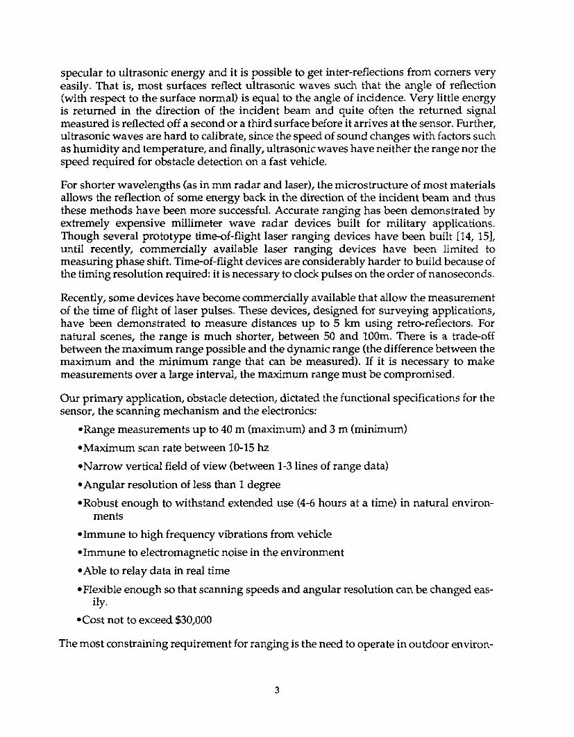
Our primary application, obstacle detection, dictated the functional specifications for the sensor, the scanning mechanism and the electronics:
.Range measurements up to 40 m (maximum) and 3 m (minimum)
*Maximum scan rate between 10-15 hz *Narrow vertical field of view (between 1-3 lines of range data) *Angular resolution of less than I degree *Robust enough to withstand extended use (4-6 hours at a time) in natural environ-
*Immune to high frequency vibrations from vehicle *Immune to electromagnetic noise in the environment
*Able to relay data in real time *Flexible enough so that scanning speeds and angular resolution can be changed eas-
*Cost not to exceed $30,000
ments
ily.
The most constraining requirement for ranging is the need to operate in outdoor environ-
3
ments where the lighting cannot be controlled. This eliminates the choice of sensors that use passive methods since they are vulnerable to poor lighting conditions. The require- ment for speed and accuracy eliminate the choice of sonar and the expense criteria elim- inates the choice of radar. Laser ranging through the use of phase shift methods is a reliable technology, but the sensors available at the time of design were limited to a range of approximately 20 m. Recently, some relatively inexpensive laser time-of-flight sensors have been used for surveying applications. The dynamic range specifications and cost limitations led us to choose such an instrument. Further, it is a field tested device that has endured a variety of operating conditions.
The other main decision was that of scanner configuration, the mechanical system in which the laser is housed and which determines the distribution of the laser beam emanating from the range finder. Since the objective is to recognize obstacles on an other- wise flat road, we didn’t think it necessary to use a dual axis range scanner (with a nodding as well as rotating mirror) that typically provides from 80 to 256 lines of range data per frame. Most of these devices are slow,providing 2 frames per second at the most. Rather, what we wanted was less data, but more often. It was estimated that 10 scan lines/second from a single line scanner would be necessary for obstacle detection at speeds of 10 m/s.
4

3. Scanner Design
3.1. Configuration
We considered two configurations for the scanner to distribute a laser beam from a single point source. The first one involved rotation of the entire rangefinding device. The advan- tage of such a configuration is that laser energy transmitted and received is not attenuated by mirrors or prisms. However there are several complications. It is necessary to use a large sophisticated slipring to transfer data and power to the instrument. Further, spin- ning a mass of several pounds brings risks stability, and increases vulnerability to natural elements and accidents.
The second configuration we considered used a rotating mirror to point the beam. This involved rotation of a tube containing a mirror (with an adjustable set angle) above the rangefinder aperture. The advantage of such a method is that the rangefinder itself is not required to move, making a safer and simpler mechanism. This design was chosen and implemented. Designed to be mounted on the front of an autonomous vehicle, the system consists of several parts:
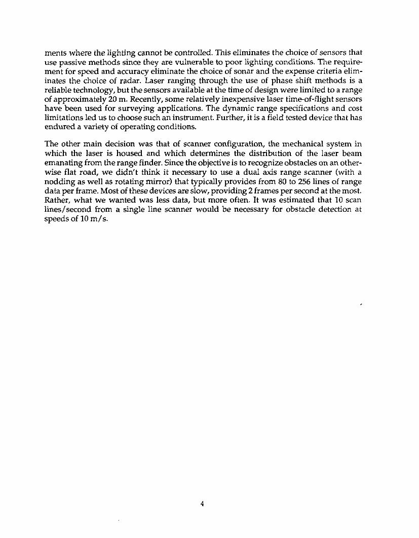
*Scanner enclosure: houses the rangefinding unit, a DC motor/encoder, rotating tow- er and an interface circuit
*Power and communications enclosure (PCE): provides the power and control signals for the scanner motor. It also contains circuitry to buffer range data from the range- finder and to relay these data to a host computer.
*Host computer: connected to the PCE by a parallel data interface to read buffered range data. Apart from processing the range data, it is also responsible for sending high level control commands (motor speed, etc.) to the PCE. These are then turned into low level controls sent to the motor.
5
These modules are shown in Figure 2.
Figure 2 Configuration of the system
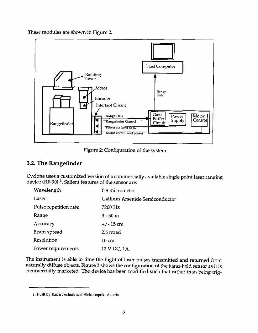
3.2. T h e Rangefinder
Cyclone uses a customized version of a commercially available single point laser ranging device (RF-90) '. Salient features of the sensor are:
Wavelength 0.9 micrometer Laser Gallium Arsenide Semiconductor Pulse repetition rate 7200 Hz Range 3-50m Accuracy +/- 15 cm Beam spread 2.5 mrad Resolution 10 cm Power requirements 12 V DC, 1A.
The instrument is able to time the flight of laser pulses transmitted and returned from naturally diffuse objects. Figure 3 shows the configuration of the hand-held sensor as it is commercially marketed. The device has been modified such that rather than being trig-
1. Built by RadarTechnik and Elekmptik, Ausha.
6

gered by hand, the laser is activated by a pulse train.
Figure 3: The rangefkder
Figure 4 shows a block diagram of the operation of the rangefinder.
Target
conductor srnitted Pulse
eceived Pulse
Measunn Device
Receiving Lens
Figure 4 Operation of rangefinding device
Other researchers have done additional work on calibrating the sensor and have found that it is possible to reduce range error, especially for measurements taken from distances of less 3 m [16,17].
7

3.2.1. Interfacing with the RangeFinder
When the rangefinder is triggered, the measured range is output on an 11 bit parallel port. Specifically, two control lines must be manipulated for the rangefinder to take a measure- ment:
*TRIGGER is a control line that, when given a rising edge, causes the rangefinder to produce a range measurement.
*LASER-INHIBIT is a control line that must be driven low for the TRIGGER inputs to be effective. We have used this line for safety purposes by ensuring that this line is never pulled low unless the tower is rotating.
Additionally, two status lines are available: -DATA-VALID is a status line. It is held high only when a good echo (reflected sig-
nal) is received by the rangefinder. *DATA-READY is a status line which is held high when the data are ready to be read.
This line is always high except for 20 microseconds while the data are in transition.
Reading data from rangefinder can be accomplished by the following algorithm. A count down timer is started after a TRIGGER pulse is issued. Immediately, a loop is initiated that checks to see if the DATA-VALID line has been pulled high. If this doesn’t happen by the time the timer completes, the data are considered to be ”missing”. If the DATA-- VALID line has been pulled high, then the algorithm waits for the DATA-READY line to be pulled high. As soon as this is done, the parallel port can be read.
3.3. Scanner Enclosure
The scanner enclosure houses the rangefinder as well as the necessary optics and electronics. Figure 5 shows a cut away view of the scanner. The noteworthy components are as follows:
*Rotating Tower: A rotating tower at the top of the scanner enclosure, contains a mir- ror that reflects the transmitted and receiving beams. The tower is driven by a cog belt powered by a motor. There is a 21 gearing ratio between the motor and the tower. A four point bearing is used to hold the tower rigidly.
*Motor/Encoder: A DC stepper motor is used to drive the rotating tower. The encod- er allows for the motion control to determine position of the motor shaft to within 0.2 degrees.
-Interface Circuit: This circuit is responsible for relaying power and data between the scanner and the remote PCE.

500 Line Encoder
nterface Circuit
Figure 5 Scanner enclosure
*Tower Motion Sensors: These sensors, mounted directly below the tower, have two functions. Firstly, they ensure that if the speed of the tower falls below a minimum speed, the laser is disabled from firing, so as to not repeatedly fire the laser at one spot. This is a safety feature designed to minimize exposure to eyes, in case the tower stalls for some reason. A second sensor is used to mark an angle (between the two sensors) in which the laser can be selectively disabled. Typically, the laser scanner is mounted on the front of a vehicle, and the field of interest is in the 180 degree area in front of the vehicle. The vehicle itself will block the rear portion of the 360 degree scan area. The second tower motion sensor enables the determina- tion of whether the tower is pointing out in front of the vehicle or towards it. This information can be used to disable the rangefmder from firing when the tower is pointing towards the vehicle. The second motion sensor is mounted 170 degrees away from the first one. This is used to indicate a "deadband on part of the 360de- g e e view(Figure 6) .
9

Tower Motion Sensors
Figure 6 Tower motion sensors
3.4. Power and Communication Enclosure
As mentioned previously, the power and control signals are not generated in the scanner enclosure. Instead a separate enclosure has been designed W E ) . When the cyclone is mounted on the front of an autonomous vehicle, the PCE is rack mounted in the interior in a 19” rack. The PCE houses the following:
*Data Buffer Circuit: generates the control signals for the rangefinder, and buffers the range data till a complete scan can be transmitted to the host computer.
*Motor Amplifier: generates the power and control for the motor that drives the tow- er.
*Power Supply: Converts the AC voltage to DC for use by the buffer circuit (12 V @0.25 A, 5V @3A) and to power the rangefinder (12 V@ 1A) and the interface cir- cuit (5V @ 0.1 A).
The configuration of the PCE is shown in Figure 7.
10

Data to
Computer
AC-DC Power
Data Buffer Data from Rangefinder
Control to Laser 4 --
1
Control to Laser
I- I I
Motor Controller Control to Motor
Figure 7 Power and Communication Enclosure
3.5. Motion Control
It is necessary to precisely control the speed of the scanner tower and hence the speed of the DC motor used to drive the tower. We were looking for a motion control system that afforded us the following:
*Precision of control: max 0.1% error in rotational velocity *Simplicity: a simple stand-alone system that can communicate over a serial interface
.ability to synchronize: each data set should be distinct, i.e, it is necessary for the mo-
We chose a high resolution DC stepped motor' that is controlled by a single stand-alone unit providing all the necessary control and power to drive the motor. This device has 25000 steps/rotation and is comparable in smoothness to the DC servo motor. This motor provides 45 in/oz. of torque. Its top speed is 1800 RPM corresponding to 15 rotations/sec of the tower. Specifications of commands like motor speed and motor diagnostics are achieved through a serial interface on the motor controller.
An encoder is mounted on the shaft of the motor and provides three separate lines from which the position of the motor shaft can be precisely determined. Channels "A" and "B" produce a pulse train of 500 pulse/rotation that is 90 degrees out of phase. This provides 2000 edges (1000rising and 1000 falling) from which the angular position of the motor can
for high level commands and diagnostics.
tor to be repeatedly synchronized with the zero angle.
1. Manufactured by Cornpumotor Inc.
11

be determined. The ‘ Z channel produces a pulse whenever the motor completes one complete rotation.
3.6. Electronic Design
There are two main circuits: the Interface Circuit that resides in the scanner enclosure, and the Datu Buffer Circuit, that resides in the PCE. The interface circuit transmits range data as it is obtained to the data buffer circuit via differential drivers and receivers. Range data are collected by the Data Buffer Circuit until the tower makes one full revolution. These data comprise one scan. When a scan is complete, the buffer circuit signals the host computer, whereupon the entire scan is transferred to the host computer for processing.
3.6.1. Interface Circuit
The Interface Circuit has three functions. First, it acts as a safety monitor. It uses one of the tower motion sensors to sense if the tower has stopped rotating. In this case, the LASER-INHIBIT signal is pulled high and the rangefinder is disabled from firing. The second function is to disable the laser from firing for part of the 360 degree scan area as mentioned earlier. This feature extends the life of the laser diode and also makes it possible to rotate the tower at a faster rate because the 7200 Hz firing rate is a RMS spec- ification. However, for applications where a 360 degree scan is needed, the disable feature can be turned off.
The third function of the circuit is to convert signals between single ended and differential form. Tn signals (range measurements) from the rangefinder are differentially trans- mitted to the buffer arcuitry, and differentially transmitted signals from the buffer circuitry are converted to TIL levels. That is, each signal is transmitted on two separate lines, such each signal is now the difference between the voltage on two lines. Ambient noise affects both lines equally, but difference between the two lines is preserved. This procedure prevents noise contamination along the cable connecting the scanner and the PCE.
3.6.2. Data Buffer Circuit
The Data Buffer Circuit has three functions: to synchronize firing of the laser with the angular position of the tower, to buffer range data from one complete scan, and to transmit the scan to a host computer. Scan data are collected and stored in two memory banks. This avoids shared memory and synchronization problems between scan storage and scan transmission. Data for a new scan is stored in one bank while the previous scan is being transmitted from the other bank. This allows for more effective utilization of the CPU on the host computer since the host computer receives a whole scan at a time, rather than having to fetch one range measurement at a time.
Synchronization of the scans, i.e. correct detection of the start of a new scan is accom- plished by the use of two quadrature pulse trains issued by the encoder: the Z and A channels. The 2 channel is asserted once per motor shaft revolution. The A channel pulses
12

1000 times per revolution of the motor shaft. One additional signal is needed to fully synchronize the scan field with the encoder signals. Since there is a 2:l gearing ratio between the motor and the tower, two pulses are received on the 2 channel and 2000 pulses are received on the A channel per rotation of the tower. It is therefore not possible to differentiate between the beginning of the first half of the scan and the beginning of the second half. To fully synchronize the scan field, the DB (dead band) signal generated by the interface circuit is used. The DB signal, used to disable the laser from firing in the back half of the scan, allows the differentiation of the front and back halves of the scan. The Z and DB signals together indicate the beginning of the scan.
The second task, buffering data for one complete scan, is accomplished through the A channel. The 2000 pulses of the channel are divided by either 2, 4, 8, or 16 (selected through DIP switches on the circuit board). This allows the number of data points per scan to be varied between 1000,500,250, and 125. The divided signal is used to trigger the laser rangefinder at appropriate angular intervals, and to store the resulting range data in memory.
The sequence of events is as follows. W (write) is asserted one clock cycle after a rising edge on the divided A signal. At this point, data from a previous T (laser trigger) is avail- able and is stored in memory. T is asserted the following clock cycle, triggering the laser and putting the resulting range data onto the memory input bus. This data are written on the next W pulse, repeating the cycle. The timing relationships are depicted in Figure 8:
CLK
Figure 8: Communication between the Interface Circuit and Data Buffer Circuit
The final task of the buffer circuit is to transmit the scan data to a computer for processing. Completed scans are signaled by the Z and DB signals (the beginning of a scan is also the end of a previous one). Upon sensing a completed scan, an interrupt request line is asserted and remains so asserted until either the mirror has made half a revolution or the computer acknowledges the interrupt. In the first case, the half revolu- tion of the mirror is signaled by a subsequent 2 pulse and indicates a time out condition; the computer has failed to respond and the data are lost. Normally, the interrupt is acknowledged by the host computer and upon its receipt, STR (data strobe) is asserted and held until IBF (input buffer full) is received. During this time, data are put on the data bus and may be read by the computer. Data is valid on the bus until IBF is asserted,
13
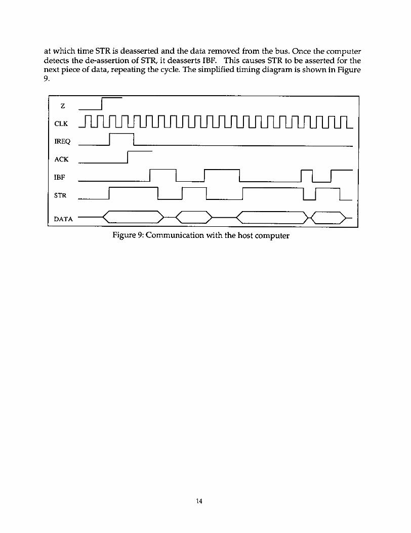
at which time STR is deasserted and the data removed from the bus. Once the computer detects the de-assertion of STR, it deasserts IBF. This causes STR to be asserted for the next piece of data, repeating the cycle. The simplified timing diagram is shown in Figure 9.
1 CLK
14

4. Applications
4.1. Obstacle Detection
In our early obstacle detection an.. avoidance experiments, we mountel ie front bumper of the Navlab. In this configuration, the scans lie in a plane parallel to the ground plane and only obstacles higher than this plane can be detected. This configura- tion is shown in Figure 10.
Cyclone on i
Figure 1 0 Cyclone mounted on the front bumper of NavLab
The scanner is mounted on a "L" bracket using five shock mounts to damp out high frequency vibration which are mainly induced by the vehicle engine.
Cyclone was also used in a downward looking configuration to obtain three dimensional information about the terrain. In Figure 11, the scanner is shown mounted in a "pendulum" configuration atop of the cab of the NavLab. The scanner pivots arqund a horizontal axis to the ground plane and runs through the left and right sides of the scanner. The downward pointing angle can be adjusted by a link at the bottom of the
15

scanner.
I I- I -n Figure 11: The "pendulum" mount for 3-D scanning
4.2. Use on the LE (360 radial scan)
More recently, Cyclone has been used for position estimation on the Locomotion Emulator (LE), one of the robots developed at the Field Robotics Center. Given the angular resolution and range accuracy of the scanner, it is possible to match features in the range data to known features on a map such that the position of the robot can be located to within 10 an. Figure 12 shows the Cyclone mounted on the LE.
Figure 12: Cyclone mounted on the Locomotion Emulator
16

Figure 13 shows data from a single scan taken from the Cyclone while the LE was navi- gating in an underground mine intersection. This scan consists of 1000 range measure- ments.
I -
Figure 13: Sample data obtained from the Cyclone
17
5. Discussion
Development of a stable system was complicated by several factors. Firstly, we were plagued by electrical noise problems. The stepper motor used to drive the scanner tower was the largest source of noise. Even after much shielding, data communication was constantly contaminated. This problem was solved by differential transmitting all signals between the scanner enclosure and the PCE.
We had a hard time finding a glass dust cover for the front of the tower. We found that quite often laser pulses were reflected back from the glass cover and were accepted as legal echoes. This was despite many efforts to treat the window with special coatings matched to the frequency of the laser, and to tilt the window. This problem has never been solved and it was determined that a modification in the rangefinder itself is necessary to compensate for this phenomena. For our experiments, we ended up manually removing a metal dust cover as necessary. Under most operating conditions (i.e. in the absence of a lot of dust), motion of the tower is sufficient to keep dust from entering the scanner.
A different set of problems are application dependant. For exampl-e, at high speeds, the lines traced by a scan on the ground (while mounted in the downward looking configu- ration) are not orthogonal to vehicle motion but lie at a velocity dependant angle to it. This is due to the relatively large amount of time taken by the rotation of the tower; the tower speed must be increased proportional to the higher vehicle speeds to prevent this effect. Another problem is due to the pitching motion of the vehicle that the Cyclone is mounted on. Given the small vertical field of view, the scan could completely miss the road (and hence any obstacle) or give the erroneous impression that the road surface lies much closer thanexpected. It is necessary to actively servo the pitch axis of the scanner to maintain a desired downward looking angle. This issue was also never dealt with.
Cyclone has proven to be a much larger success for applications other than the ones it was designed. Recent results in map based position estimation when mounted on a slow moving vehicle, navigating in underground mines, are unprecedented. The-range and the accuracy afforded by the system make it ideally suited for this sort of application.
Acknowledgments
The authors would like to acknowledge Kevin Lynch and Thanathip Vidyasirinun for developing early versions of the buffer circuitry. Gary Shaffer helped in the many nights spent debugging the system and wrote helpful software utilities to view the data. Lonnie Devier assembled and disassembled the scanner many times and helped with much of the mounting work. Richard Clow performed many of the calibration tests. Bryon Smith designed and built the safety sensor and Gary Baun fabricated the two mounts that the scanner u t i l i .
References
1 S. Singh, P. Keller, Obstacle Detection for high Speed Autonomous Nazigation, In Proceedings IEEE International Conference on Robotics and Automation, Sacramento CA, April 1991.
D. Feng, S. Singh, B. H. Krogh, Implementation of Dynamic Obstacle Avoidance on the CMU NavLab, In Proceedings IEEE Conference on Systems Engineering, Pittsburgh, PA, 1990.
G. Shaffer et al, Position Estimdorfor UndergroundMine Equipment, in Proceedings 10th WVU In- ternational Mining Electrotechnology Conference, Morgantown, W. Va., July 1990.
R. A. Jarvis, A Perspedive on Range Finding Techniques for Computer Vision, IEEE Transactions on Pattern Analysis and Machine Intelligence, Vol. 5, March 1983.
P. Besl, Rnnge Imaging Sensors, Technical Report, General Motors Research Lab. GMR 6090, March 1988.
2
3
4
5
6 S. T. Barnard, M. A. Fischler, Computational Stereo, Computing Surveys, Vol14. Nd. 4. Decem- ber 1982.
7 L. H. Mathies, Stereo vision for plnnefaly rovers: stochustic modeling to naar real-time implmenta- tion, Jet Propulsion Lab Technical Report, JPL Ir8131, January 1991.
E. Krotkov, Focusing, International Journal of Computer Vision, 1. 1987, Kluwer Academic Publishers.
K. Ikeuchi and B. K. P. Horn, N u m e r i d Shapefrom Shading and Occluding Boundaries, Artificial Intelligence, Vol. 17, August 1984.
10 R. J. Popplestone, C. M. Brown, A. P. Ambler and G. F. Crawford, Forming Models of Plune and Cylinder Faceted Bodies from Light Stripes, in Proceedings 4th Infernational Ioint Conference on Ar- tzf icd Intelligence, 1975.
I1 M. Rioux, Laser Rnnge Finder Bused on Synchronized Scanners, in Robot Sensors, Vol. 1. Editor A.
8
9
l'ugh, Publ. IFS Limited. -
12 T. Kanade, A. Gruss, L. R. Carley, A VLSI Sensor Bused Rangefinding System, in Proceedings 5th
19
International Symposium on Robotics Research, 1989.
13 R. 0. Duda and D. Nitzan, Law Level Processing of Registered Intensity and Range Data, in Pro- ceedings, 3rd International Joint Conference on Artificial Intelligence, 1976.
14 R. A Lewis and A. R. Johnston, A Scanning Laser RangeJinder fora Robotic Vehicle, in Proceedings 5th InternationaI foint Conference Artiftcial Intelligence, 1978.
15 R. A. Jarvis, A h e r time-of-flight range scanner f i r robotic vision, Technical Report Australian National University, TRCS81-IO, 1981
16 S. Sedas and J. Gonzalez, Analytic and Experimental Characterizaiion of a Radial laser Range Find- er, Technical Report to appear, Robotics Institute, Carnegie Mellon University.
17 S. Sedas and J. Gonzalez, Improvement in Robof Position Estimation Through Accurate Sensor Characferization, Submitted to IFAC Symposium on Intelligent Components and Instruments for Control Applications, 7992..
20