Embed Size (px)
Citation preview
Central Washington UniversityScholarWorks@CWU
All Undergraduate Projects Undergraduate Student Projects
Spring 2018
CWU Bottle Opener ManufacturingAustin [email protected]
Follow this and additional works at: https://digitalcommons.cwu.edu/undergradproj
Part of the Manufacturing Commons
This Undergraduate Project is brought to you for free and open access by the Undergraduate Student Projects at ScholarWorks@CWU. It has beenaccepted for inclusion in All Undergraduate Projects by an authorized administrator of ScholarWorks@CWU. For more information, please [email protected].
Recommended CitationSanford, Austin, "CWU Bottle Opener Manufacturing" (2018). All Undergraduate Projects. 73.https://digitalcommons.cwu.edu/undergradproj/73
2017-2018
CWU Bottle Opener Manufacturing AUSTIN SANFORD
1
Contents INTRODUCTION .......................................................................................................................... 2
DESIGN & ANALYSIS ................................................................................................................. 3
METHODS & CONSTRUCTION ................................................................................................. 5
TESTING METHOD ...................................................................................................................... 7
BUDGET/SCHEDULE/PROJECT MANAGEMENT .................................................................. 9
DISCUSSION ............................................................................................................................... 10
CONCLUSION ............................................................................................................................. 11
ACKNOWLEDGEMENTS .......................................................................................................... 11
APPENDIX A – Analyses ............................................................................................................ 12
APPENDIX B – Sketches, Assembly drawings, Sub-assembly drawings, Part drawings ........... 24
APPENDIX C – Parts List and Costs ........................................................................................... 34
APPENDIX D – Budget ............................................................................................................... 34
APPENDIX E - Schedule ............................................................................................................ 35
APPENDIX F – Expertise and Resources .................................................................................... 38
APPENDIX G – Evaluation sheet (Testing) ................................................................................. 38
APPENDIX H – Testing Report ................................................................................................... 39
APPENDIX I – Testing Data ........................................................................................................ 43
APPENDIX J – Resume ............................................................................................................... 44
2
Abstract Previous students from the Mechanical Engineering Technology program came up with a
method to help raise funds and awareness for the program. The idea was to manufacture and sell CWU bottle openers. However, a more efficient manufacturing method was needed. The aspect of the process that would have the most impact on the manufacturing time and material efficiency was the CNC machining of the parts. There were many potential variables to change to improve the process, but the main changes were to the cutter speeds and stock material size. Consequently, the changes made to stock material size reduced the number of operations to be done at the CNC and allowed for multiple parts to be nested into one stock piece. The new method produces three parts per cycle as opposed to one and takes less time than the original cycle time for producing only one part. The new method can produce 3.5 times more parts in an hour. In addition to the improved machine time efficiency, there is less wasted material in the new method. Since the stock thickness was reduced to net thickness, less material needs to be removed and therefore there is more than 10% less wasted material.
INTRODUCTION
Description
Central Washington University has ASME and SME engineering clubs. In the past, an idea to raise money for the clubs was to create CWU bottle openers using the machine shop and sell them or promote the clubs. However, the current method to create the bottle openers is inefficient in both of terms of time per part and material wasted. A new method to reduce the inefficacies of the process would be to rethink how the CNC machine mills out the bottle openers. The current method mills out each part individually. Not only is each part milled one at a time, they all require a second operation that mills out the backside of the part. This extra operation also needs special jaws to grip the specific geometry of the bottle opener, reducing their utility to only one part. A new method, which can produce multiple parts per cycle, and negate the need for a second operation should vastly improve the efficiency of producing the bottle openers. Motivation
The need to improve the current method of creating the CWU bottle openers was the motivation of this project. Measuring cost per part, and by time to make each part on the CNC mill, and by measuring the times, it takes to produce a part from raw material to finished product, will produce evidence of improvement. Function Statement
The process must create multiple parts using only one setup on the CNC mill to reduce complexity and negate the current need of a special holding fixture. Requirements
1) The process must be able to mill 5 parts at a time.
3
2) The overall process must be able produce 50 parts per hour. 3) The process must have 95% success rate on go/no go quality control. 4) Manufacturing parts must cost less than $1.50 a part.
Success Criteria
If the new process improves cost and time efficiency, and simplicity, then the project will be a success. Scope
This project will look at the entire process of the manufacturing process of the CWU bottle openers, including the raw stock all the way to quality control. Benchmark
The current method making the bottle openers is the minimum standards for the new method. However, the new process will try to incorporate current industry practices for mass production. Companies also have various manufacturing techniques to increase parts per hour, quality, and decrease cost per part. Use of personal ties to industry in machining find the most effective method of tooling and manufacturing.
Success
Success of this project will be determined by whether or not more parts per hour is created with sufficient quality compared to the old method of creating them.
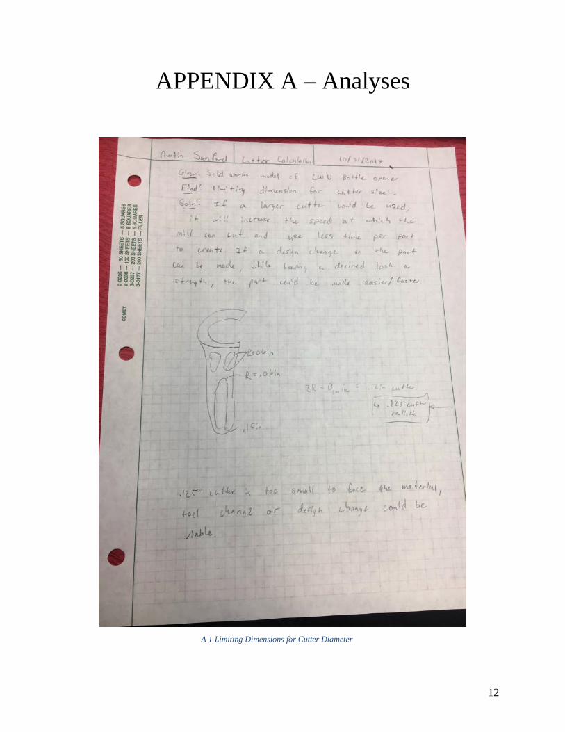
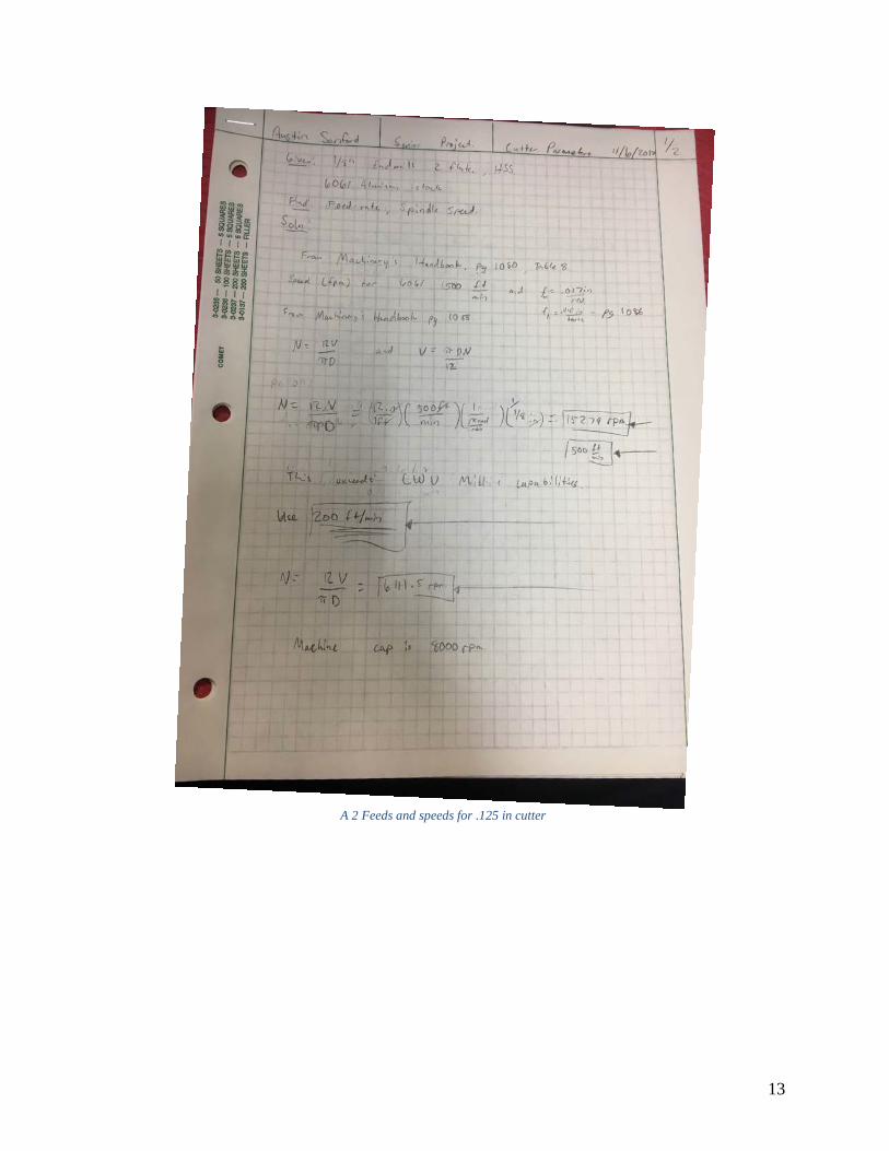
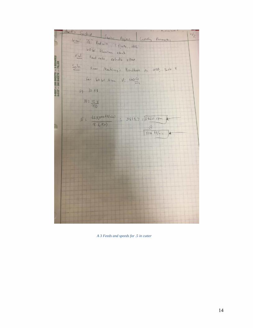
DESIGN & ANALYSIS When dealing with manufacturing optimization, one of the main concerns is the speed of production. One of the requirements for the new process is that it can produce 50 parts per hour. Part of what limits production speed is the size of tooling that is required. The results in appendix A1 found that the smallest diameter of a fillet, the limiting size for tooling, is .125in. simply measuring every fillet in the model yielded this limiting dimension. The size of the cutters and the material is what dictates milling speeds. Found in appendix A2, the .125in cutter was to spin at about 6000rpm and travel 200 feet per minute when using 6061 aluminum. Following the analysis of the cutting speed of the .125in cutter is the analysis of the .500in cutter. As shown in appendix A3, it can spin at 3820 rpm and travel 500 feet per minute. Aside from tooling, another way to increase production speeds is to limit operations, and to increase the amount of parts per cycle. One of the major benefits of this method compared to the old method is that it will only require one set up, therefore reducing the number of operations required to mill out the parts. In addition, there will be the ability of producing more parts per
4
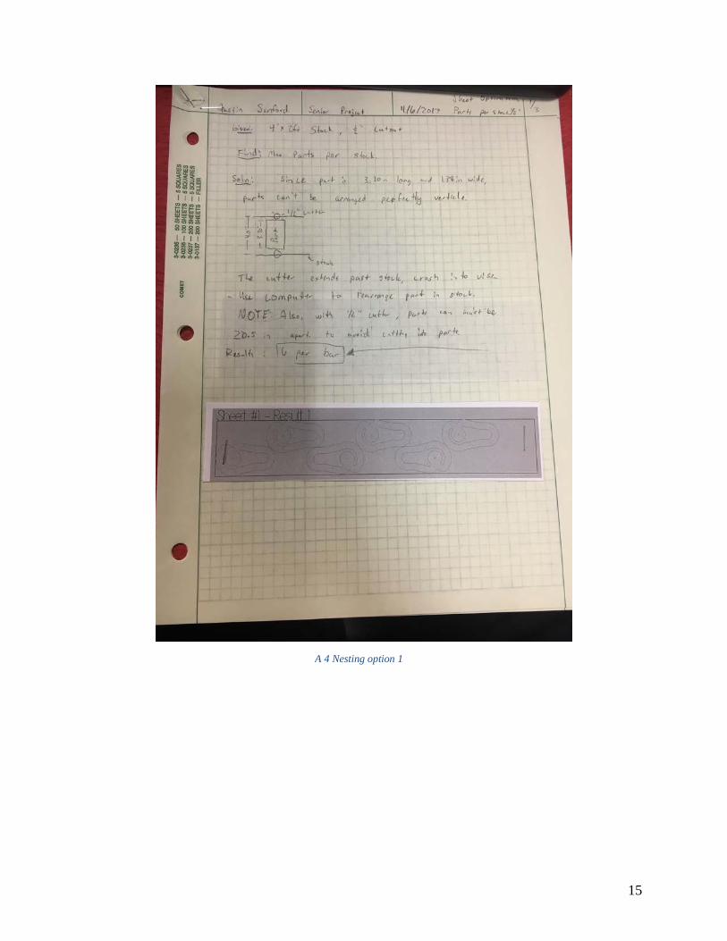
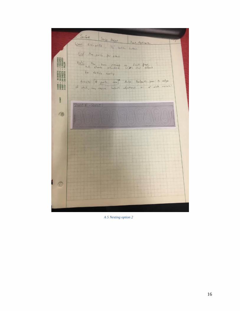
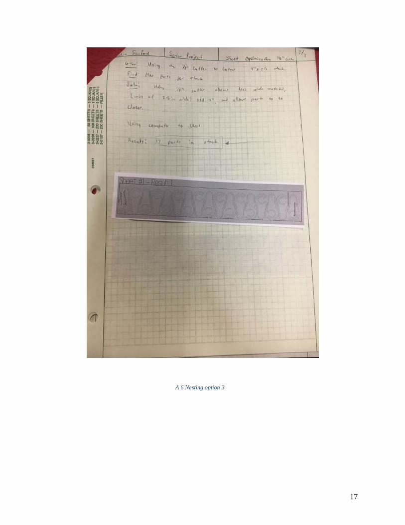
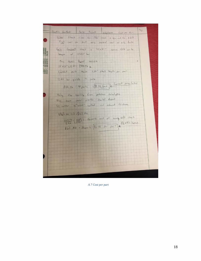
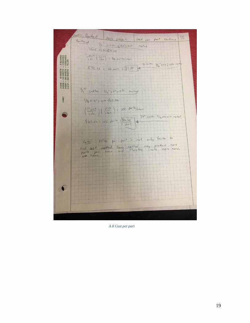
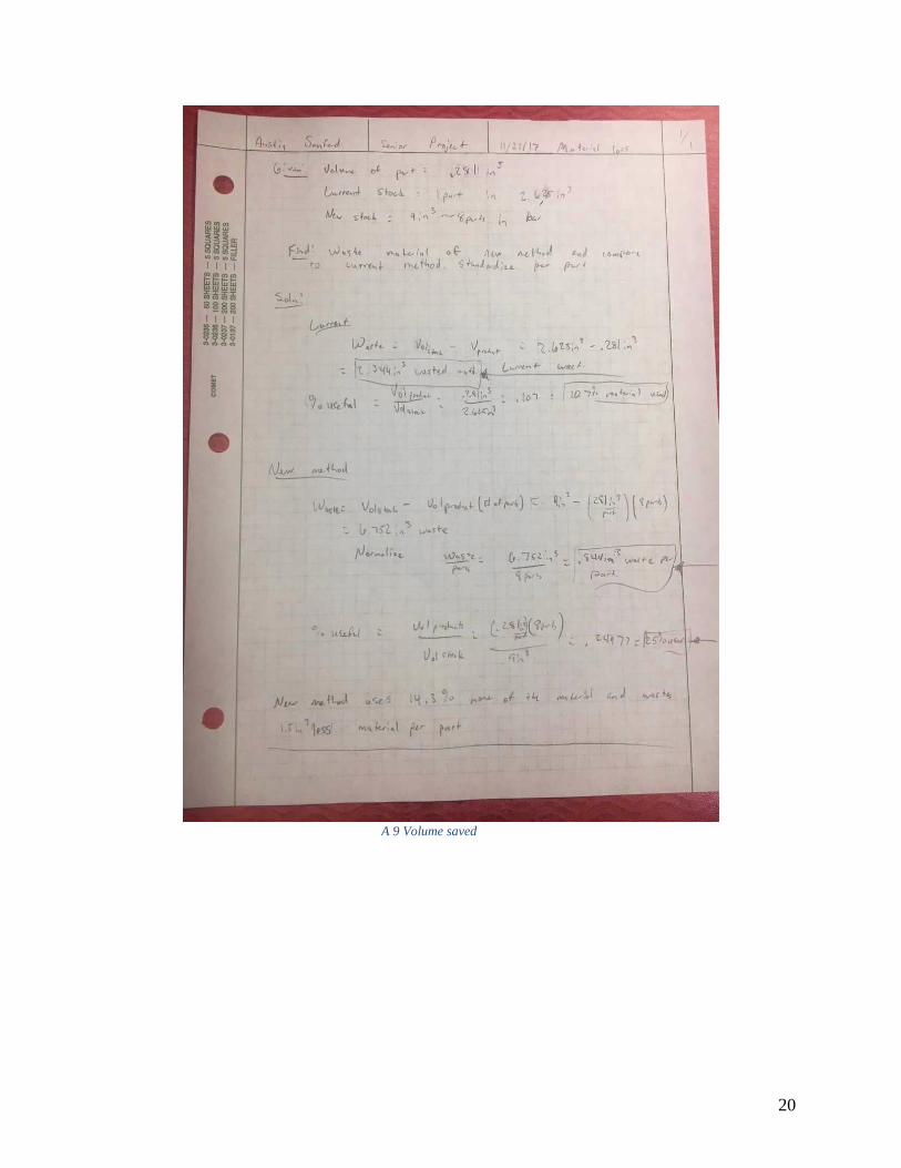
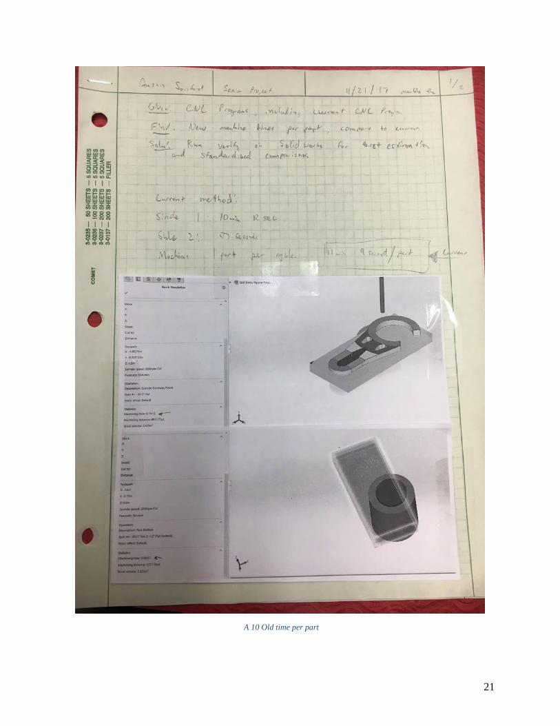
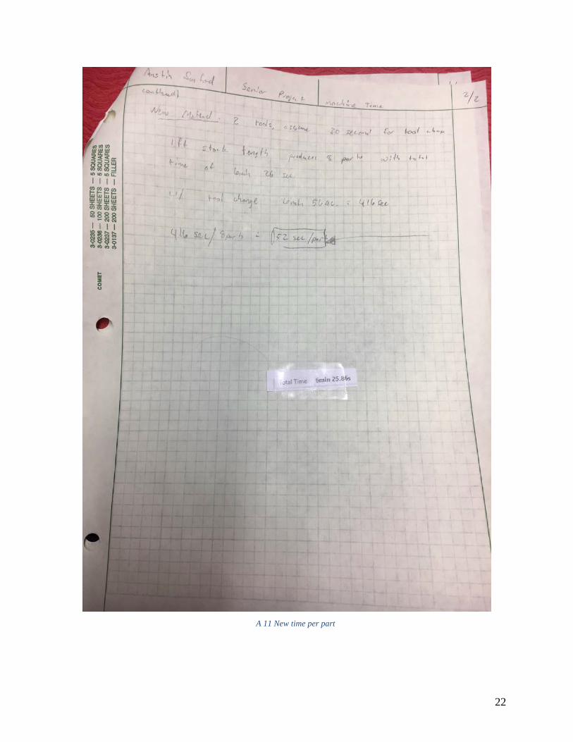
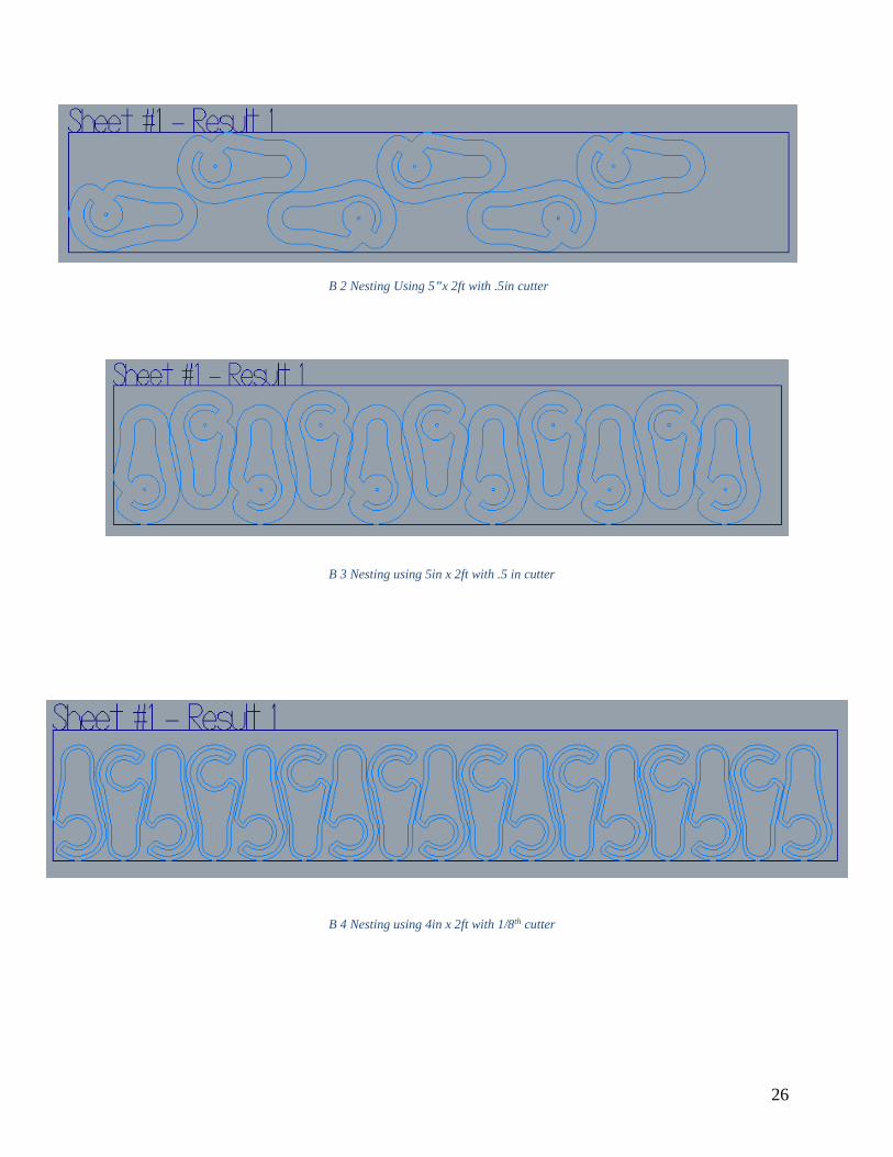
cycle by nesting parts into a piece of flat bar. In appendix A4, using 4in x 2ft stock size and the .5in end mill to cut out the parts resulted in 6 parts being made per cycle. Appendix A5 shows a different nesting option. If the size of the stock was 5in x 2ft, and still used the .5in end mill to cut out the parts, there could be 11 parts made per cycle. Appendix A6 shows the final nesting option. Using the .125in cutter to cut out the parts and using a 4in. x 2ft stock size resulted in making 17 parts per cycle, which fulfills the requirement of producing at least five parts per cycle. This ultimately will be the used nesting option. Reducing the stock size to 1ft may be necessary, but this method still should produce the most parts per cycle compared to the other methods. Another important aspect of mass production is the cost of the parts. Given the nesting options found in the previous analysis, it is important to find the most cost effective method. Not using machine time in calculating price per parts, since CWU is donating machine time, appendix A7 found the price per part. This calculation assumes a stock length of 12ft and uses the current prices from Metals Depot, and assumes the initial nesting options is used. It found that the original method costs $1.14 per part. The first nesting option shown to cost $1.72 per part. Appendix A8 continues the cost per part analysis with the second and third nesting options. The cost per part turned out to be $1.10 per part for nesting option 2, and only $0.61 per part for nesting option 3. This further supports using nesting option 3, which now also shows to fulfill the requirement of costing less than $1.50 to produce. Appendix A9 deals with analysis the amount of waste of the original and new method. It found that the original method only used 11% of the stock material. The new method improves this by using 25% of the material. The amount of time in the machine should also be limited. Appendix A10 shows that, using the verification tool in Solidworks, it takes 11 minutes and 9 seconds per part. Appendix A11 continues the analysis of the machine time using the new method. It found, using Mastercam’s verification tool that the new method will finish a cycle in 6 minutes and 26 seconds. This is already lower than the original method, however, taking into consideration that one cycle of the new method produces eight parts and therefore it takes about 52 seconds per part to make each part.
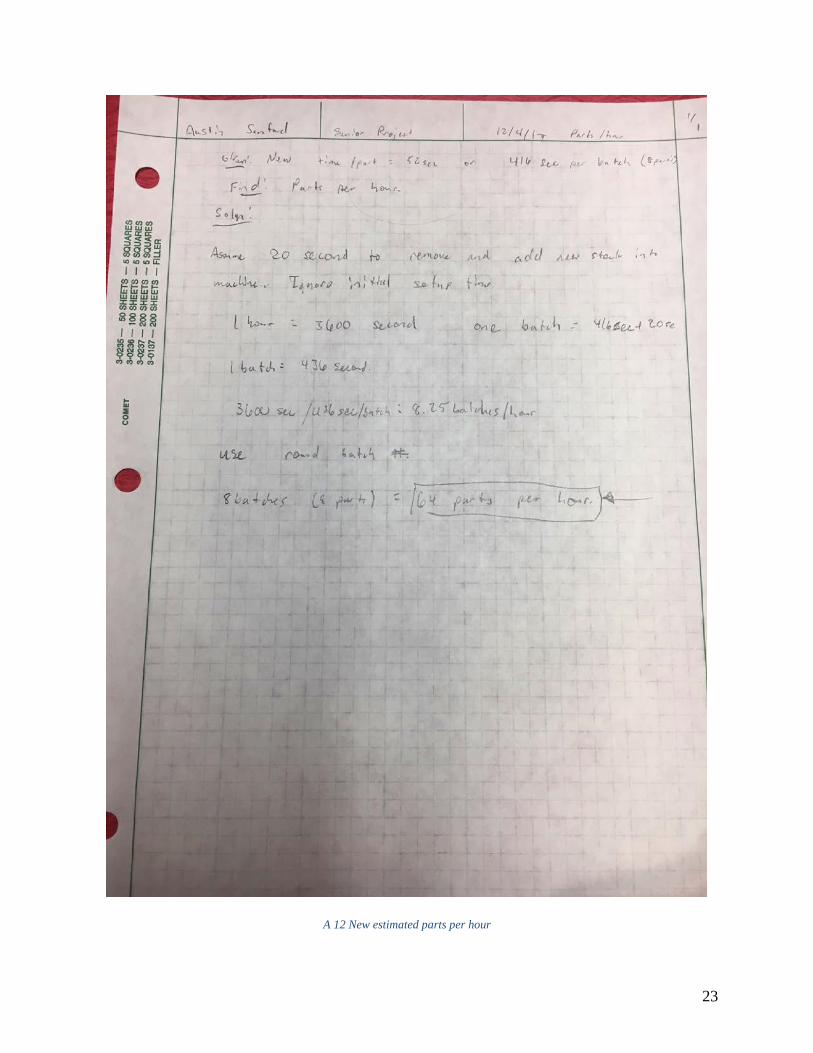
Using 2-foot stock pieces would produce too much overhang while in the vise. The vise is only 6 inches wide; therefore, 1-foot stock sizes should be satisfactory. This would leave only 3 inches of overhang on each side as opposed to 9 inches. This should not heavily effect the previous analysis of costs per part, however will add more time to manufacture and fewer parts per cycle. Using the time per part found in the previous analysis, appendix A12 found that this new method could produce up to 8 cycles in an hour, or about 64 parts per hour. This fulfils the initial requirement of producing at least 50 parts per hour.
Due to limiting the process to a vise, the predictions in appendix A11 were inaccurate. Because of the surface finish being unpassable due to the overhang of the foot long stock material. Instead of foot long stock material, 6-inch long stock proves to reduce chatter. This means that one cycle produces only three parts. In addition, speeds and feeds changed to produce better surface finish and reduce vibration in the material.
5
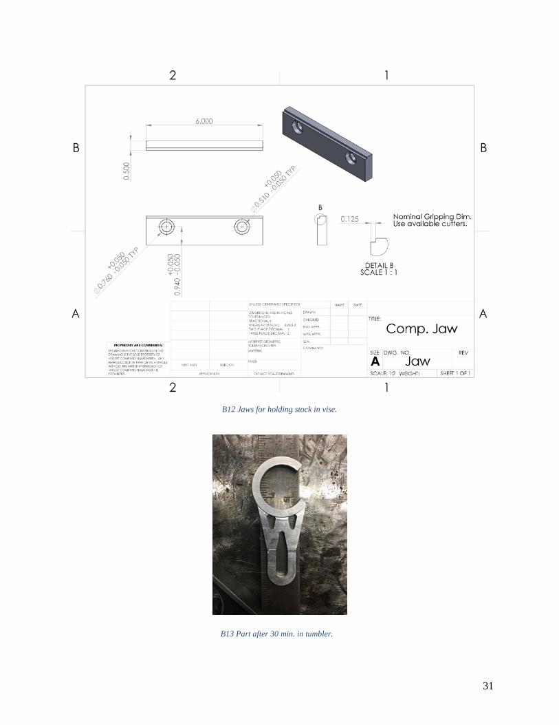
METHODS & CONSTRUCTION The process was design for the CWU machine shop and the CWU machine shop will carry out the process. Since this project is tackling a current method of manufacturing of the CWU bottle openers, the majority of effort is trying to optimize the process to be better than the current method. This includes taking less time to create each opener, having less waste, and simplifying the process. Since this project is engineering a manufacturing a process more so than creating a device, there is not a true construction phase. However, the methods behind developing this process comes mainly from first-hand experiences. Industry tends to find effective and efficient methods to cut time and cost of manufacturing parts. Methods for creating a large mass of product include making multiple parts out of one stock piece of material, limiting operations and different work offsets, avoid special tooling unless needed, pushing machining speeds, and minimizing wasted material. There are many strategies to achieve these goals. For instance, an optimal stock size may be determined that can reduce machine time. In addition, different work holding methods will be more effective than others will. Since the machines at CWU are not very large, the vise is the best method to hold a bar of material. Although this project has initial requirements unrelated to the current method, nearly every calculation dealing with the efficiency of the process is calculated for both the current and new method and then be compared. If the process ends up improved overall, it will be successful enough, and may warrant additional improvements later on. An unmeasurable benefit that the new process should have is simplicity. The current method requires a special set of jaws bolted on to the vise to complete the second side of the bottle openers. The new method should have the capability of not needing special attention to follow through. If a beginning-machining student can follow the directions without much intervention to produce parts, the project is successful. A pair of simple jaws will make the process simpler. Appendix B-12 shows the drawing of the jaws manufactured. By having a step in the jaws to hold, the stock at a fixed height there is less chance for error for the operator to make. It should also reduce set up time for transitioning between cycles on the machine since there is no parallel bars in the mix. Fortunately, there is jaw blanks in the machine shop available. Milling the step in the jaws right before the first operation ensures the jaws are square relative to the machine. Sawing the received stock into 12 1-foot sections took 33 minutes.
6
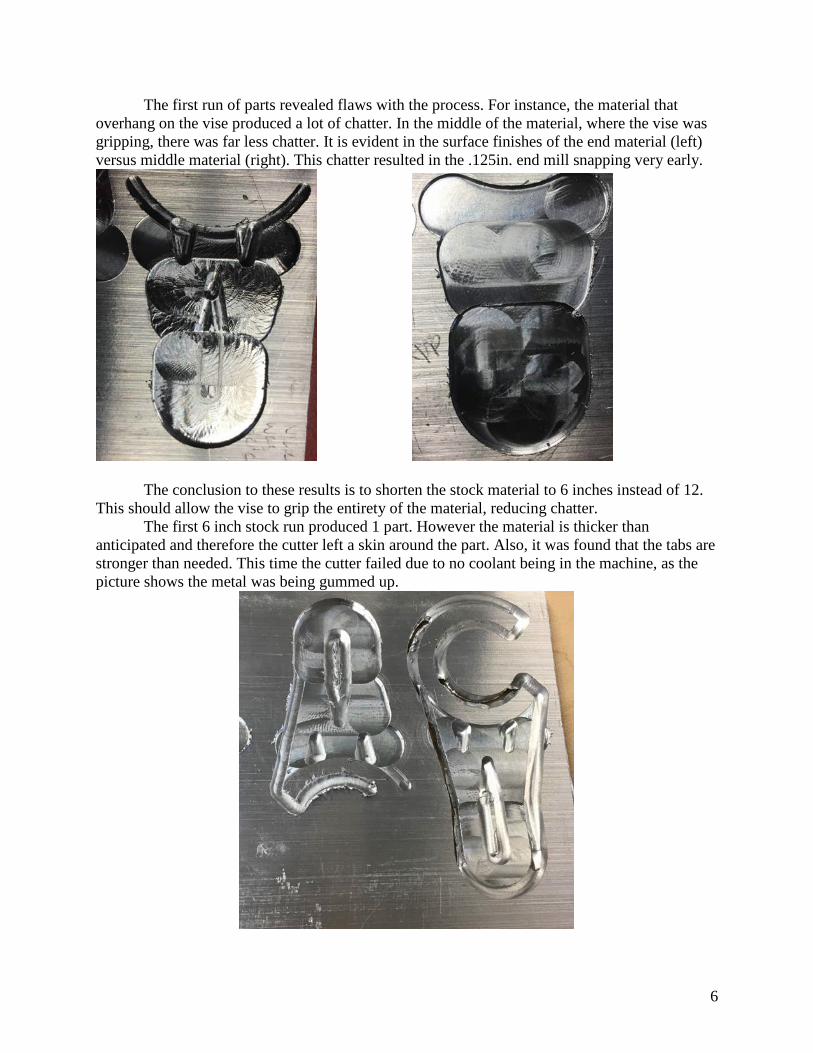
The first run of parts revealed flaws with the process. For instance, the material that overhang on the vise produced a lot of chatter. In the middle of the material, where the vise was gripping, there was far less chatter. It is evident in the surface finishes of the end material (left) versus middle material (right). This chatter resulted in the .125in. end mill snapping very early.
The conclusion to these results is to shorten the stock material to 6 inches instead of 12. This should allow the vise to grip the entirety of the material, reducing chatter.
The first 6 inch stock run produced 1 part. However the material is thicker than anticipated and therefore the cutter left a skin around the part. Also, it was found that the tabs are stronger than needed. This time the cutter failed due to no coolant being in the machine, as the picture shows the metal was being gummed up.
7
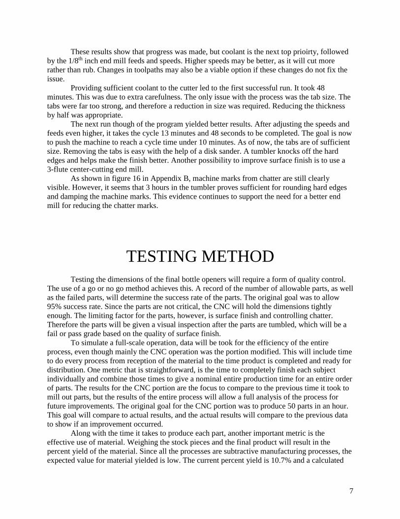
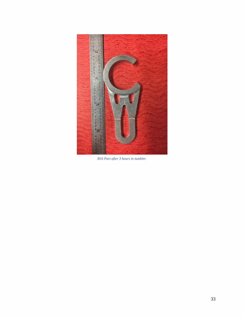
These results show that progress was made, but coolant is the next top prioirty, followed by the 1/8th inch end mill feeds and speeds. Higher speeds may be better, as it will cut more rather than rub. Changes in toolpaths may also be a viable option if these changes do not fix the issue. Providing sufficient coolant to the cutter led to the first successful run. It took 48 minutes. This was due to extra carefulness. The only issue with the process was the tab size. The tabs were far too strong, and therefore a reduction in size was required. Reducing the thickness by half was appropriate. The next run though of the program yielded better results. After adjusting the speeds and feeds even higher, it takes the cycle 13 minutes and 48 seconds to be completed. The goal is now to push the machine to reach a cycle time under 10 minutes. As of now, the tabs are of sufficient size. Removing the tabs is easy with the help of a disk sander. A tumbler knocks off the hard edges and helps make the finish better. Another possibility to improve surface finish is to use a 3-flute center-cutting end mill. As shown in figure 16 in Appendix B, machine marks from chatter are still clearly visible. However, it seems that 3 hours in the tumbler proves sufficient for rounding hard edges and damping the machine marks. This evidence continues to support the need for a better end mill for reducing the chatter marks.
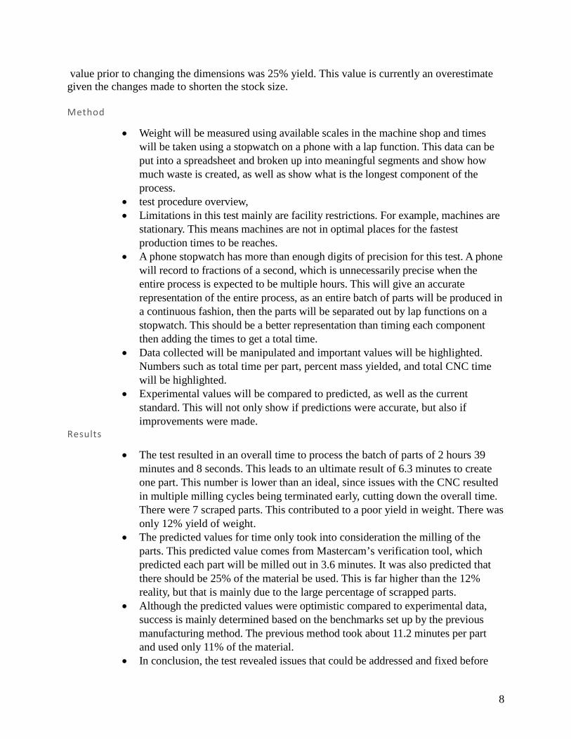
TESTING METHOD Testing the dimensions of the final bottle openers will require a form of quality control. The use of a go or no go method achieves this. A record of the number of allowable parts, as well as the failed parts, will determine the success rate of the parts. The original goal was to allow 95% success rate. Since the parts are not critical, the CNC will hold the dimensions tightly enough. The limiting factor for the parts, however, is surface finish and controlling chatter. Therefore the parts will be given a visual inspection after the parts are tumbled, which will be a fail or pass grade based on the quality of surface finish. To simulate a full-scale operation, data will be took for the efficiency of the entire process, even though mainly the CNC operation was the portion modified. This will include time to do every process from reception of the material to the time product is completed and ready for distribution. One metric that is straightforward, is the time to completely finish each subject individually and combine those times to give a nominal entire production time for an entire order of parts. The results for the CNC portion are the focus to compare to the previous time it took to mill out parts, but the results of the entire process will allow a full analysis of the process for future improvements. The original goal for the CNC portion was to produce 50 parts in an hour. This goal will compare to actual results, and the actual results will compare to the previous data to show if an improvement occurred. Along with the time it takes to produce each part, another important metric is the effective use of material. Weighing the stock pieces and the final product will result in the percent yield of the material. Since all the processes are subtractive manufacturing processes, the expected value for material yielded is low. The current percent yield is 10.7% and a calculated
8
value prior to changing the dimensions was 25% yield. This value is currently an overestimate given the changes made to shorten the stock size. Method
• Weight will be measured using available scales in the machine shop and times will be taken using a stopwatch on a phone with a lap function. This data can be put into a spreadsheet and broken up into meaningful segments and show how much waste is created, as well as show what is the longest component of the process.
• test procedure overview, • Limitations in this test mainly are facility restrictions. For example, machines are
stationary. This means machines are not in optimal places for the fastest production times to be reaches.
• A phone stopwatch has more than enough digits of precision for this test. A phone will record to fractions of a second, which is unnecessarily precise when the entire process is expected to be multiple hours. This will give an accurate representation of the entire process, as an entire batch of parts will be produced in a continuous fashion, then the parts will be separated out by lap functions on a stopwatch. This should be a better representation than timing each component then adding the times to get a total time.
• Data collected will be manipulated and important values will be highlighted. Numbers such as total time per part, percent mass yielded, and total CNC time will be highlighted.
• Experimental values will be compared to predicted, as well as the current standard. This will not only show if predictions were accurate, but also if improvements were made.
Results
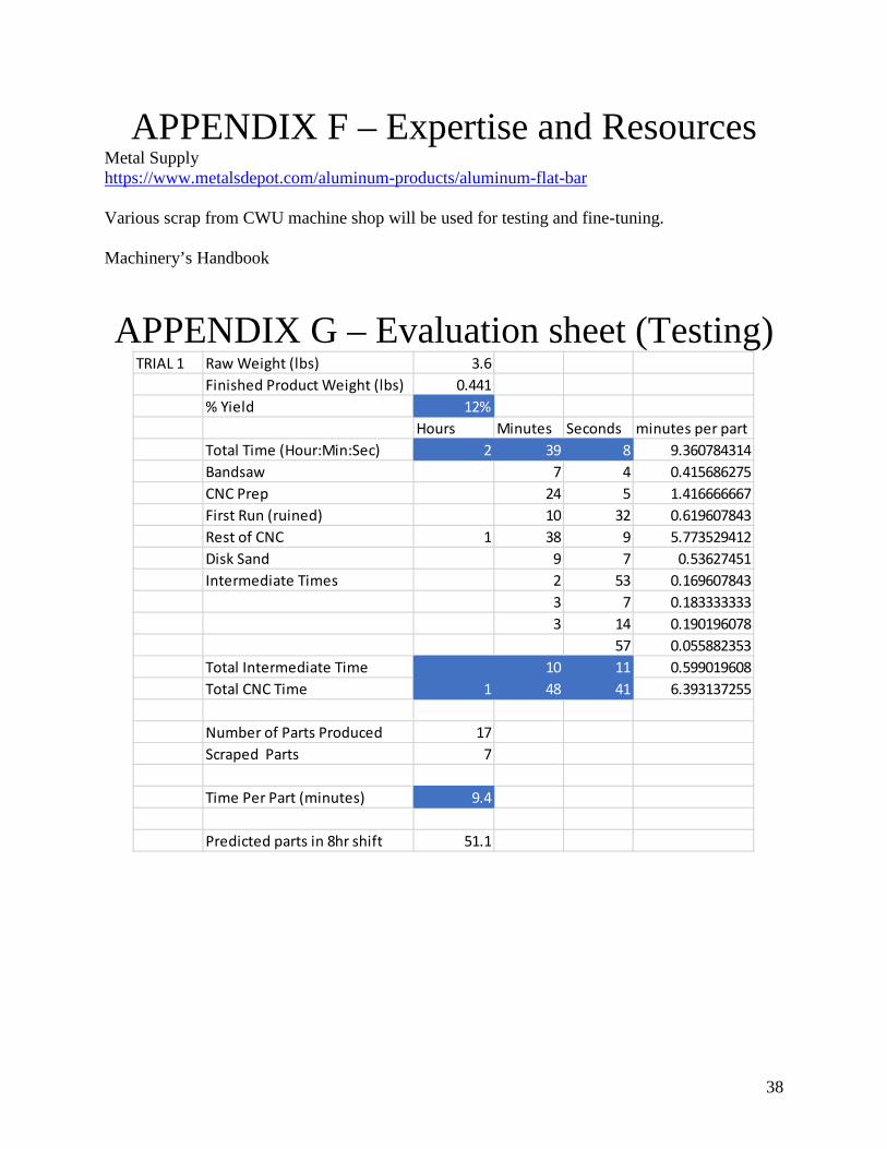
• The test resulted in an overall time to process the batch of parts of 2 hours 39 minutes and 8 seconds. This leads to an ultimate result of 6.3 minutes to create one part. This number is lower than an ideal, since issues with the CNC resulted in multiple milling cycles being terminated early, cutting down the overall time. There were 7 scraped parts. This contributed to a poor yield in weight. There was only 12% yield of weight.
• The predicted values for time only took into consideration the milling of the parts. This predicted value comes from Mastercam’s verification tool, which predicted each part will be milled out in 3.6 minutes. It was also predicted that there should be 25% of the material be used. This is far higher than the 12% reality, but that is mainly due to the large percentage of scrapped parts.
• Although the predicted values were optimistic compared to experimental data, success is mainly determined based on the benchmarks set up by the previous manufacturing method. The previous method took about 11.2 minutes per part and used only 11% of the material.
• In conclusion, the test revealed issues that could be addressed and fixed before
9
testing again. However, the results did not meet predicted values due to unforeseen problems, but they are still better than benchmarks previously made. This indicates that there has been an improvement to the manufacturing method.
BUDGET/SCHEDULE/PROJECT MANAGEMENT
Budget
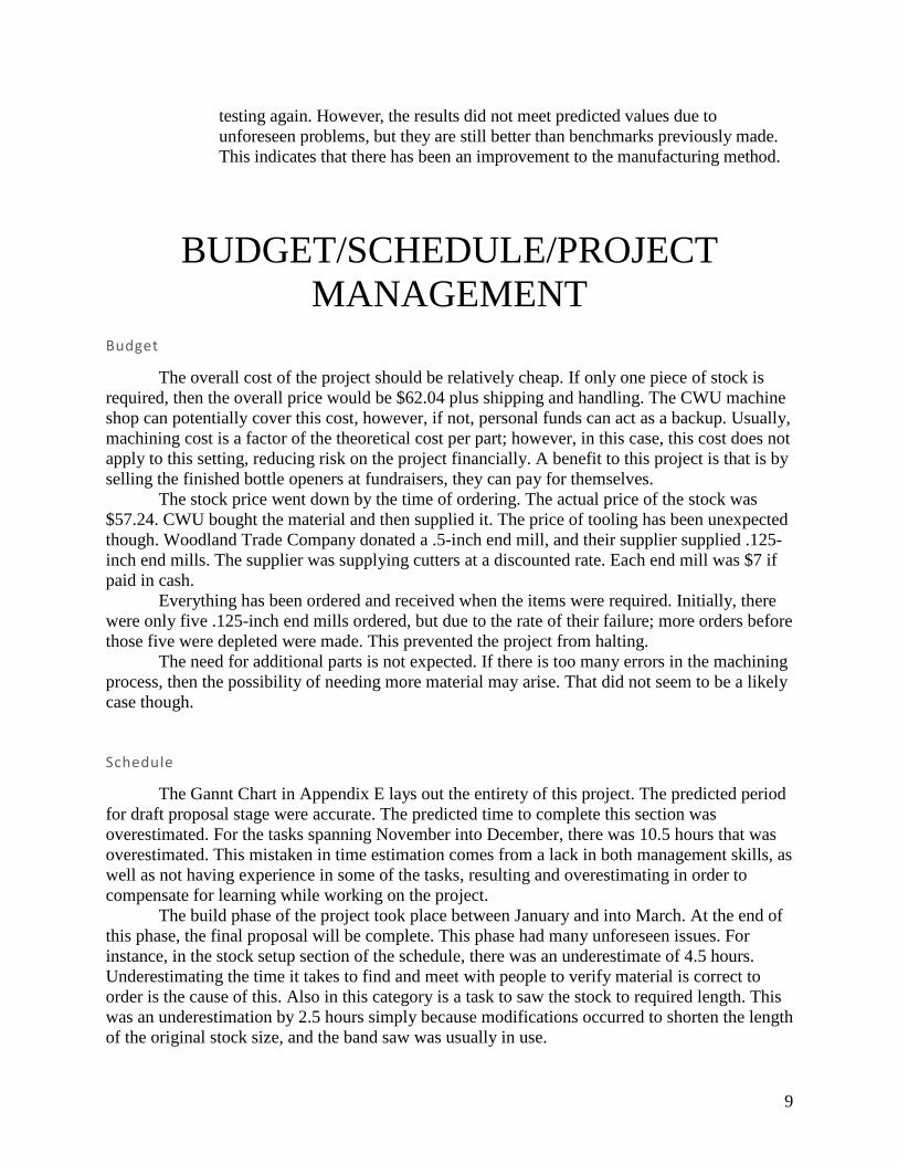
The overall cost of the project should be relatively cheap. If only one piece of stock is required, then the overall price would be $62.04 plus shipping and handling. The CWU machine shop can potentially cover this cost, however, if not, personal funds can act as a backup. Usually, machining cost is a factor of the theoretical cost per part; however, in this case, this cost does not apply to this setting, reducing risk on the project financially. A benefit to this project is that is by selling the finished bottle openers at fundraisers, they can pay for themselves.
The stock price went down by the time of ordering. The actual price of the stock was $57.24. CWU bought the material and then supplied it. The price of tooling has been unexpected though. Woodland Trade Company donated a .5-inch end mill, and their supplier supplied .125-inch end mills. The supplier was supplying cutters at a discounted rate. Each end mill was $7 if paid in cash.
Everything has been ordered and received when the items were required. Initially, there were only five .125-inch end mills ordered, but due to the rate of their failure; more orders before those five were depleted were made. This prevented the project from halting.
The need for additional parts is not expected. If there is too many errors in the machining process, then the possibility of needing more material may arise. That did not seem to be a likely case though. Schedule
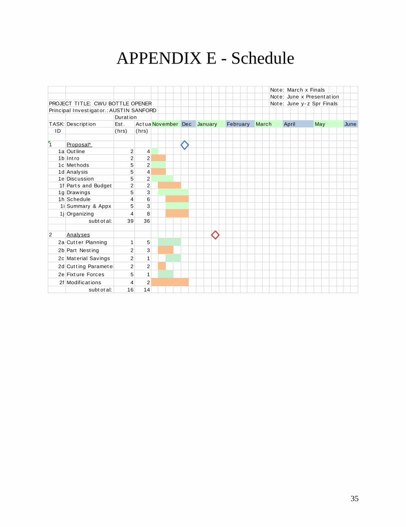
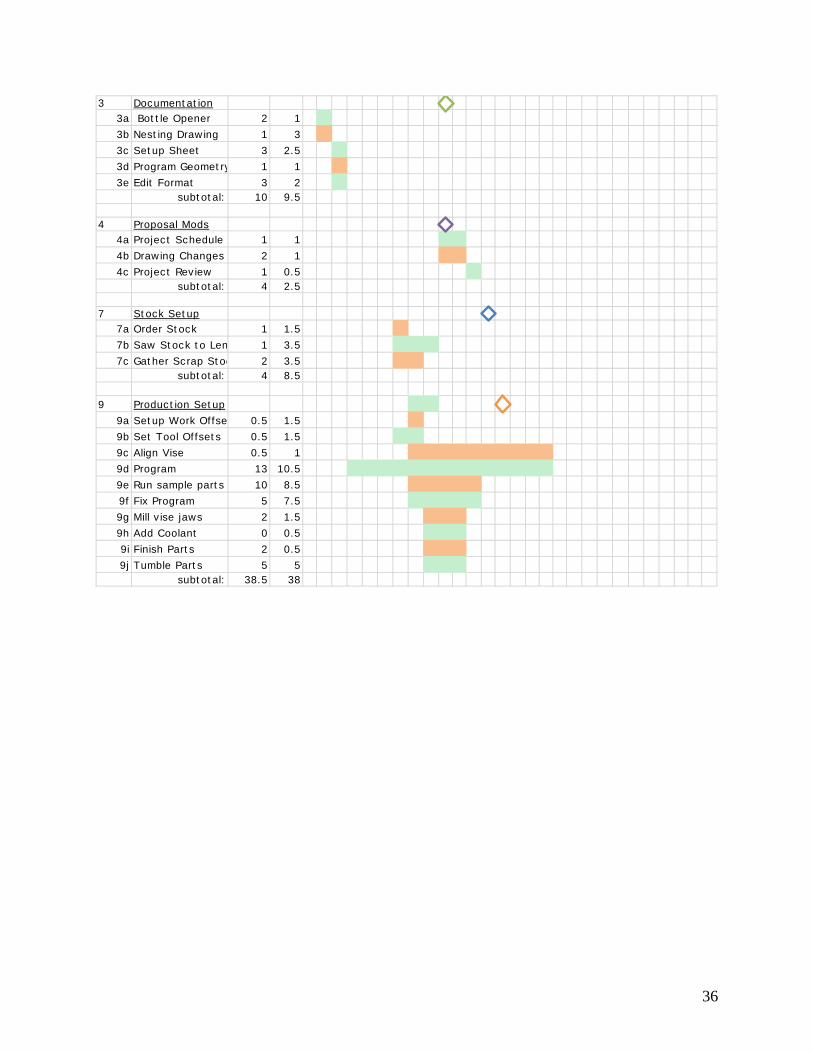
The Gannt Chart in Appendix E lays out the entirety of this project. The predicted period for draft proposal stage were accurate. The predicted time to complete this section was overestimated. For the tasks spanning November into December, there was 10.5 hours that was overestimated. This mistaken in time estimation comes from a lack in both management skills, as well as not having experience in some of the tasks, resulting and overestimating in order to compensate for learning while working on the project. The build phase of the project took place between January and into March. At the end of this phase, the final proposal will be complete. This phase had many unforeseen issues. For instance, in the stock setup section of the schedule, there was an underestimate of 4.5 hours. Underestimating the time it takes to find and meet with people to verify material is correct to order is the cause of this. Also in this category is a task to saw the stock to required length. This was an underestimation by 2.5 hours simply because modifications occurred to shorten the length of the original stock size, and the band saw was usually in use.
10
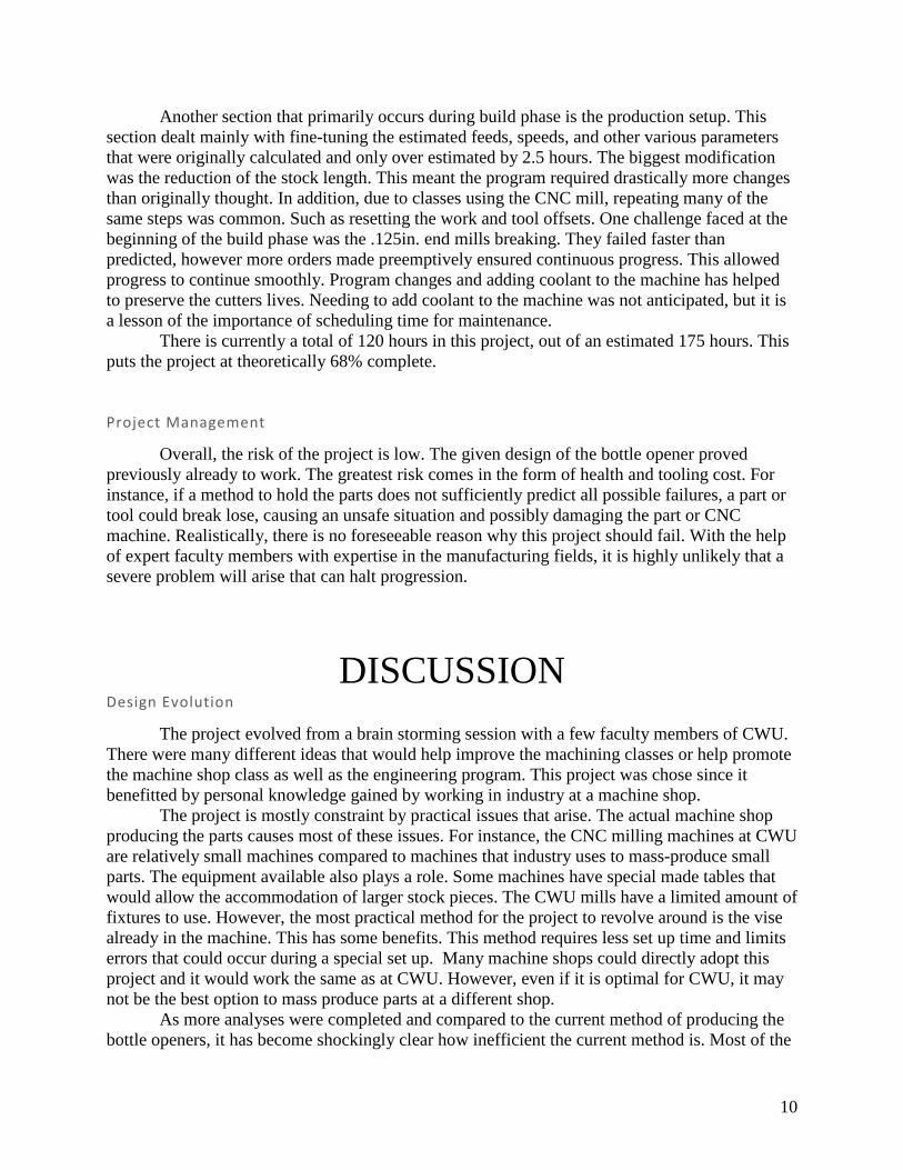
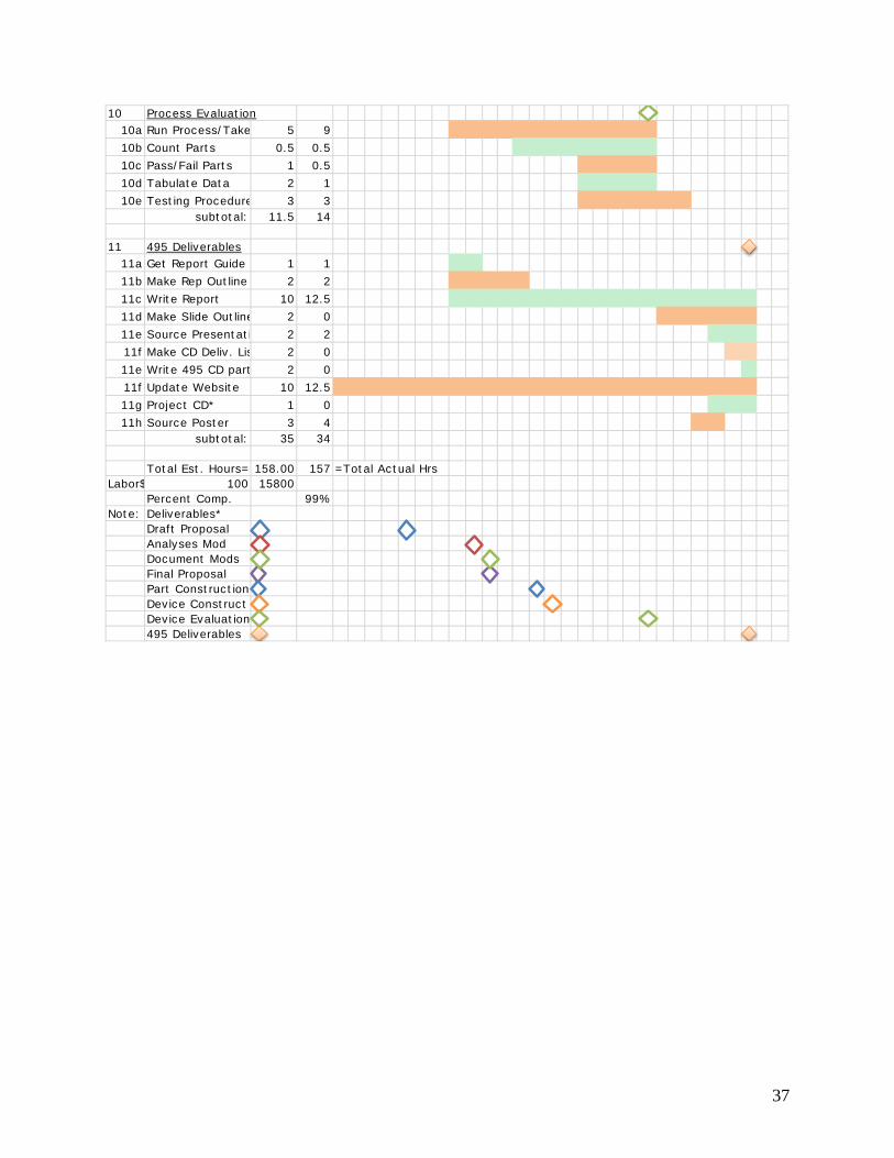
Another section that primarily occurs during build phase is the production setup. This section dealt mainly with fine-tuning the estimated feeds, speeds, and other various parameters that were originally calculated and only over estimated by 2.5 hours. The biggest modification was the reduction of the stock length. This meant the program required drastically more changes than originally thought. In addition, due to classes using the CNC mill, repeating many of the same steps was common. Such as resetting the work and tool offsets. One challenge faced at the beginning of the build phase was the .125in. end mills breaking. They failed faster than predicted, however more orders made preemptively ensured continuous progress. This allowed progress to continue smoothly. Program changes and adding coolant to the machine has helped to preserve the cutters lives. Needing to add coolant to the machine was not anticipated, but it is a lesson of the importance of scheduling time for maintenance. There is currently a total of 120 hours in this project, out of an estimated 175 hours. This puts the project at theoretically 68% complete. Project Management
Overall, the risk of the project is low. The given design of the bottle opener proved previously already to work. The greatest risk comes in the form of health and tooling cost. For instance, if a method to hold the parts does not sufficiently predict all possible failures, a part or tool could break lose, causing an unsafe situation and possibly damaging the part or CNC machine. Realistically, there is no foreseeable reason why this project should fail. With the help of expert faculty members with expertise in the manufacturing fields, it is highly unlikely that a severe problem will arise that can halt progression.
DISCUSSION Design Evolution
The project evolved from a brain storming session with a few faculty members of CWU. There were many different ideas that would help improve the machining classes or help promote the machine shop class as well as the engineering program. This project was chose since it benefitted by personal knowledge gained by working in industry at a machine shop. The project is mostly constraint by practical issues that arise. The actual machine shop producing the parts causes most of these issues. For instance, the CNC milling machines at CWU are relatively small machines compared to machines that industry uses to mass-produce small parts. The equipment available also plays a role. Some machines have special made tables that would allow the accommodation of larger stock pieces. The CWU mills have a limited amount of fixtures to use. However, the most practical method for the project to revolve around is the vise already in the machine. This has some benefits. This method requires less set up time and limits errors that could occur during a special set up. Many machine shops could directly adopt this project and it would work the same as at CWU. However, even if it is optimal for CWU, it may not be the best option to mass produce parts at a different shop. As more analyses were completed and compared to the current method of producing the bottle openers, it has become shockingly clear how inefficient the current method is. Most of the
11
analysis has been straightforward; however, a critical portion has not. That portion being a way to calculate tab geometry to hold the parts in the stock while the mill continues machining. Tabs are the industry standard for holding parts in the original stock to prevent parts flying and causing harm to operators and machines. However, after much research and trying to reach out to industry with no response, it seems there is no easy way to calculate how large to make the tabs. The process should not make the tabs very large, since they should be able to be broken by hand power or simple finishing processes like tumbling. The current strategy is to test different tab thickness, starting with a default setting from Mastercam.
CONCLUSION This is successful. The project did not reach many of the calculated expected values, but it has shown to be an improvement nonetheless over the current manufacturing method. For instance, the time to create parts decreased. As testing has shown and can be seen in Appendix G, the new method can produce a part every 7.1 minutes, whereas the current method takes about 11.2 minutes to produce a part. Without official testing in production environment, the time to complete a cycle in the machine decreased to about 10 minutes from 11 minutes and 9 seconds. This is a significant improvement because the new process is only a 1-operation program compared to the 2-operation previous process, and produces three parts compared to one. This alone increases the parts per hour by a factor of about 3.3. Another reason that this project is a success is that it only costs $0.80 to manufacture each part. This is an improvement over the current $1.14 it costs currently. Importantly, $0.80 is a price can easily be marked up to make a profit to fund the CWU engineering clubs. With slight variations in nesting, it may be possible to fit another part on the stock to reduce the price all the way down to $0.60 per part. As noted before, these calculations only take into account the price of stock since the school donates machine time. In addition, the new process simplifies into only one operation on the CNC instead of two. This is an improvement since the machine does no longer require a change in work set-up, which decreases complexity but also should reduce time per part since there is less set up time. This is also a quality of life improvement in that there is no need for special vise jaws. Keeping track of special equipment is hard to do when many students utilize the shop, and if not used frequently, can easily be lost in storage.
ACKNOWLEDGEMENTS Special thanks should go to Ted Bramble and Matt Burvee. They are the ones to set this project into motion after having complications with a prior project. Ted has also personally been a resource for his expertise in machining. Thank you Dr. Johnson and Professor Pringle for advising this project as well as provide manufacturing expertise to give guidance and ability to apply best practices for creating efficient manufacturing processes.
12
APPENDIX A – Analyses
A 1 Limiting Dimensions for Cutter Diameter
13
A 2 Feeds and speeds for .125 in cutter
14
A 3 Feeds and speeds for .5 in cutter
15
A 4 Nesting option 1
16
A 5 Nesting option 2
17
A 6 Nesting option 3
18
A 7 Cost per part
19
A 8 Cost per part
20
A 9 Volume saved
21
A 10 Old time per part
22
A 11 New time per part
23
A 12 New estimated parts per hour
24
APPENDIX B – Sketches, Assembly drawings, Sub-assembly drawings, Part
drawings, Manufacturing Pictures
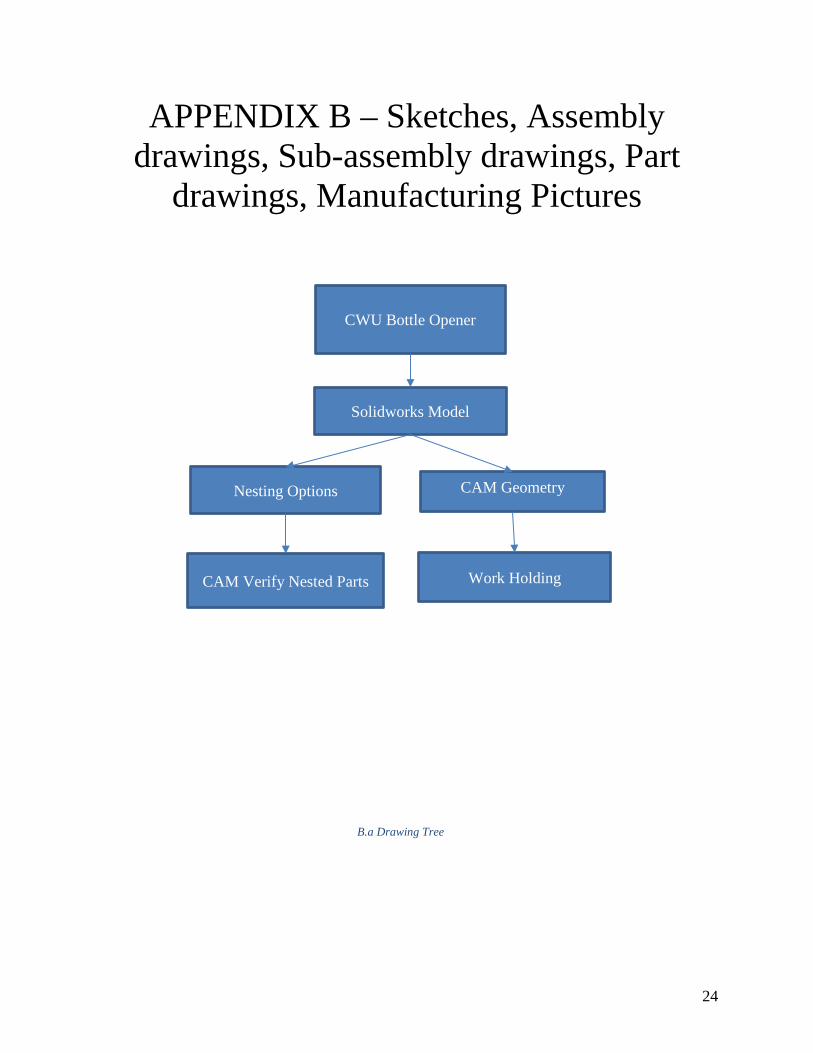
CWU Bottle Opener
Nesting Options
Solidworks Model
Work Holding CAM Verify Nested Parts
CAM Geometry
B.a Drawing Tree
25
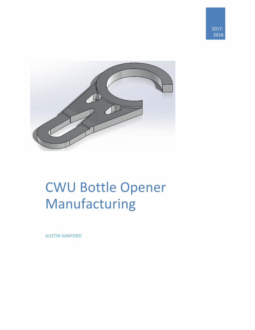
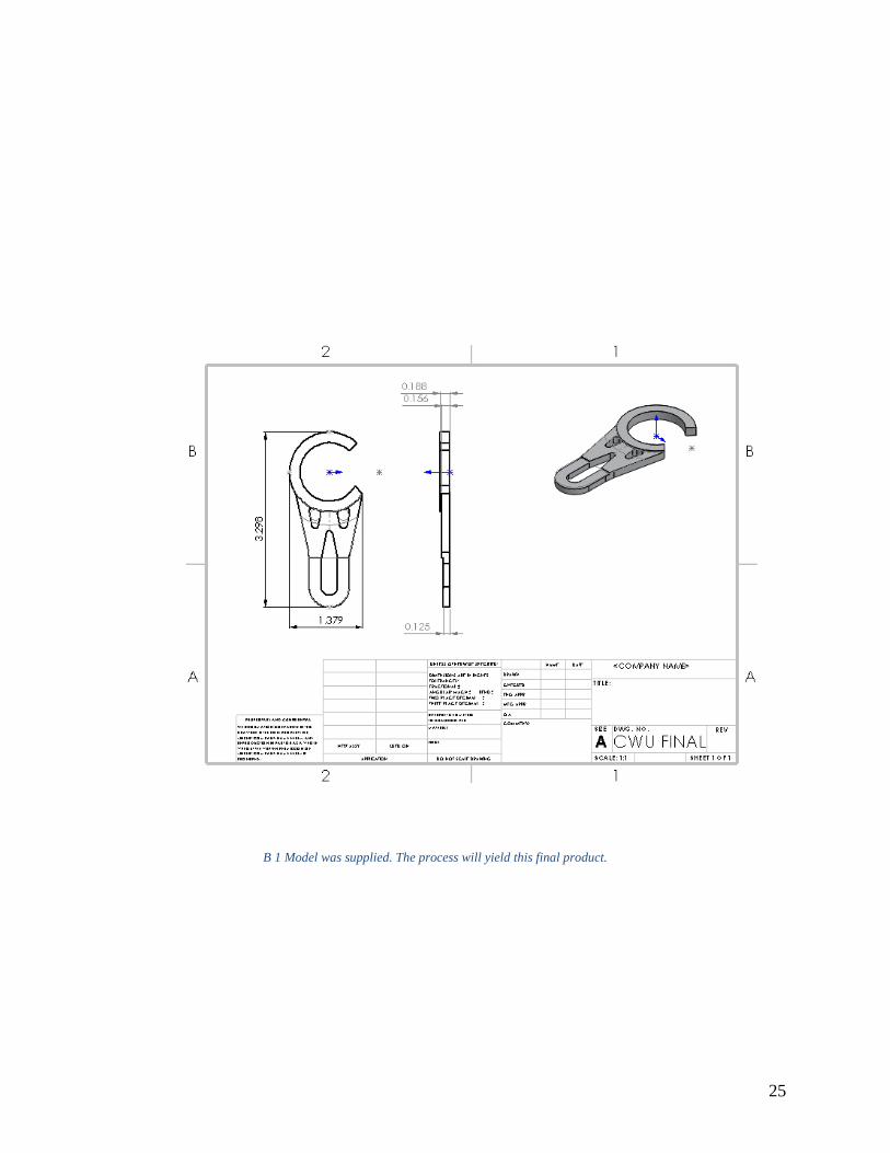
B 1 Model was supplied. The process will yield this final product.
26
B 2 Nesting Using 5”x 2ft with .5in cutter
B 3 Nesting using 5in x 2ft with .5 in cutter
B 4 Nesting using 4in x 2ft with 1/8th cutter
27
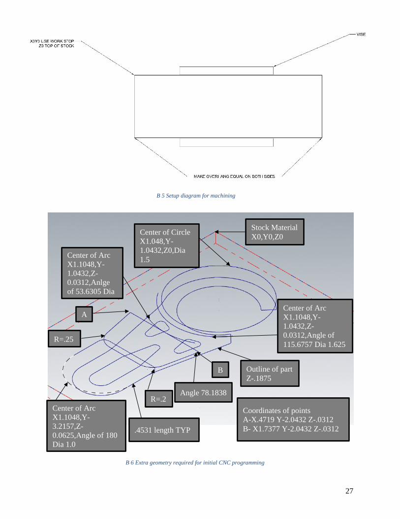
B 5 Setup diagram for machining
B 6 Extra geometry required for initial CNC programming
Stock Material X0,Y0,Z0
Outline of part Z-.1875
Center of Arc X1.1048,Y-1.0432,Z-0.0312,Anlge of 53.6305 Dia
Center of Circle X1.048,Y-1.0432,Z0,Dia 1.5
Center of Arc X1.1048,Y-1.0432,Z-0.0312,Angle of 115.6757 Dia 1.625
A
B
Coordinates of points A-X.4719 Y-2.0432 Z-.0312 B- X1.7377 Y-2.0432 Z-.0312
Center of Arc X1.1048,Y-3.2157,Z-0.0625,Angle of 180 Dia 1.0
.4531 length TYP
R=.25
R=.2 Angle 78.1838
28
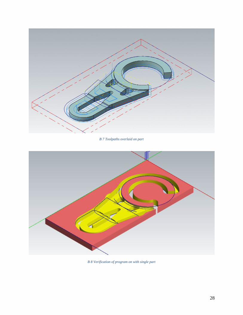
B 7 Toolpaths overlaid on part
B 8 Verification of program on with single part
29
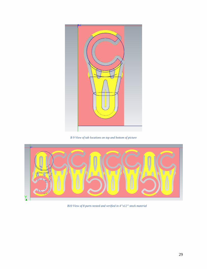
B 9 View of tab locations on top and bottom of picture
B10 View of 8 parts nested and verified in 4”x12” stock material
30
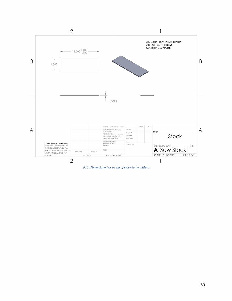
B11 Dimensioned drawing of stock to be milled.
31
B12 Jaws for holding stock in vise.
B13 Part after 30 min. in tumbler.
32
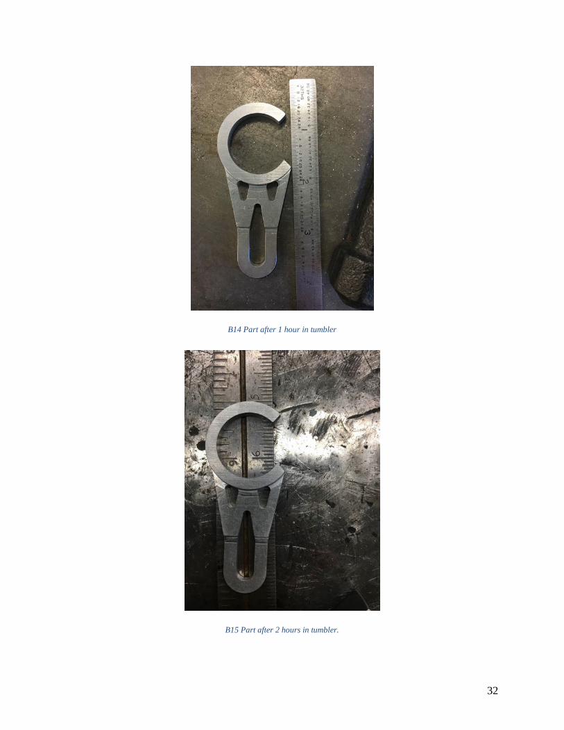
B14 Part after 1 hour in tumbler
B15 Part after 2 hours in tumbler.
33
B16 Part after 3 hours in tumbler.
34
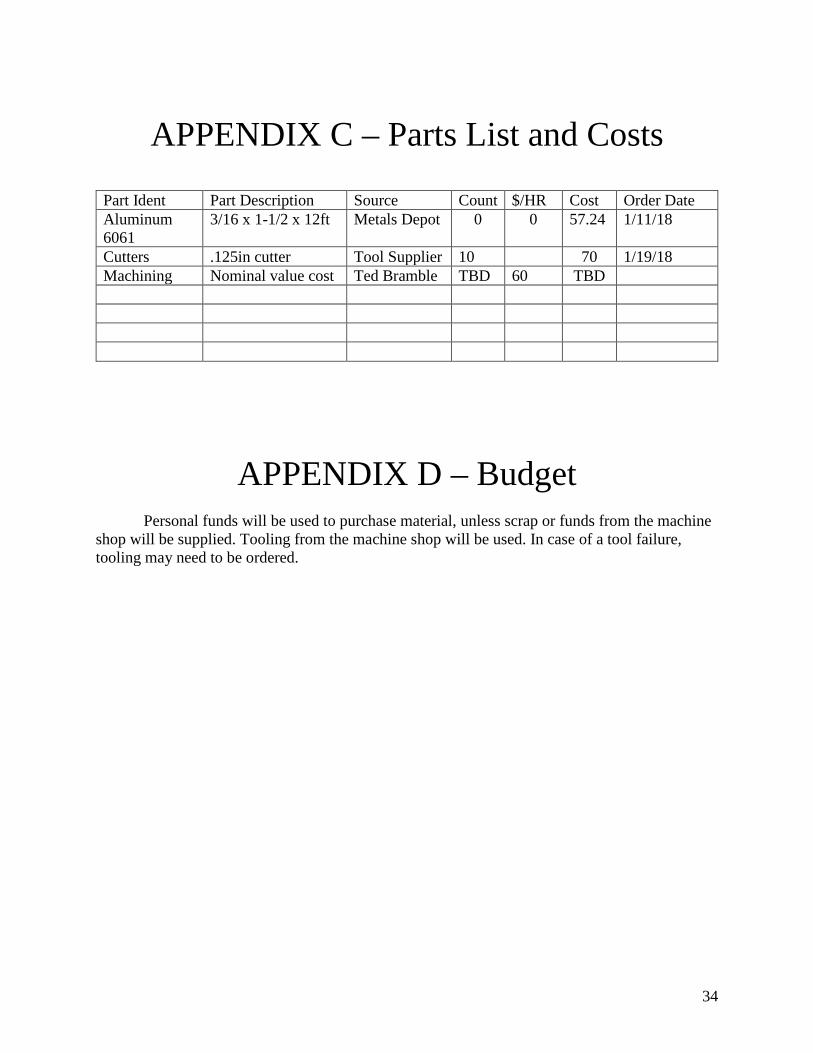
APPENDIX C – Parts List and Costs
Part Ident Part Description Source Count $/HR Cost Order Date Aluminum 6061
3/16 x 1-1/2 x 12ft Metals Depot 0 0
57.24 1/11/18
Cutters .125in cutter Tool Supplier 10 70 1/19/18 Machining Nominal value cost Ted Bramble TBD 60 TBD
APPENDIX D – Budget
Personal funds will be used to purchase material, unless scrap or funds from the machine shop will be supplied. Tooling from the machine shop will be used. In case of a tool failure, tooling may need to be ordered.
35
APPENDIX E - Schedule
Note: March x FinalsNote: June x Presentation
PROJECT TITLE: CWU BOTTLE OPENER Note: June y-z Spr FinalsPrincipal Investigator.:AUSTIN SANFORD
DurationTASK: Description Est. ActuaNovember Dec January February March April May June ID (hrs) (hrs)
1 Proposal*1a Outline 2 41b Intro 2 21c Methods 5 21d Analysis 5 41e Discussion 5 21f Parts and Budget 2 21g Drawings 5 31h Schedule 4 61i Summary & Appx 5 31j Organizing 4 8
subtotal: 39 36
2 Analyses2a Cutter Planning 1 52b Part Nesting 2 32c Material Savings 2 12d Cutting Parameter 2 22e Fixture Forces 5 12f Modifications 4 2
subtotal: 16 14
36
3 Documentation3a Bottle Opener 2 13b Nesting Drawing 1 33c Setup Sheet 3 2.53d Program Geometry 1 13e Edit Format 3 2
subtotal: 10 9.5
4 Proposal Mods4a Project Schedule 1 14b Drawing Changes 2 14c Project Review 1 0.5
subtotal: 4 2.5
7 Stock Setup7a Order Stock 1 1.57b Saw Stock to Len 1 3.57c Gather Scrap Stoc 2 3.5
subtotal: 4 8.5
9 Production Setup9a Setup Work Offse 0.5 1.59b Set Tool Offsets 0.5 1.59c Align Vise 0.5 19d Program 13 10.59e Run sample parts 10 8.59f Fix Program 5 7.59g Mill vise jaws 2 1.59h Add Coolant 0 0.59i Finish Parts 2 0.59j Tumble Parts 5 5
subtotal: 38.5 38
37
10 Process Evaluation10a Run Process/Take 5 910b Count Parts 0.5 0.510c Pass/Fail Parts 1 0.510d Tabulate Data 2 110e Testing Procedure 3 3
subtotal: 11.5 14
11 495 Deliverables11a Get Report Guide 1 111b Make Rep Outline 2 211c Write Report 10 12.511d Make Slide Outline 2 011e Source Presentati 2 211f Make CD Deliv. Lis 2 011e Write 495 CD part 2 011f Update Website 10 12.511g Project CD* 1 011h Source Poster 3 4
subtotal: 35 34
Total Est. Hours= 158.00 157 =Total Actual HrsLabor$ 100 15800
Percent Comp. 99%Note: Deliverables*
Draft ProposalAnalyses ModDocument ModsFinal ProposalPart ConstructionDevice ConstructDevice Evaluation495 Deliverables
38
APPENDIX F – Expertise and Resources Metal Supply https://www.metalsdepot.com/aluminum-products/aluminum-flat-bar Various scrap from CWU machine shop will be used for testing and fine-tuning. Machinery’s Handbook
APPENDIX G – Evaluation sheet (Testing)
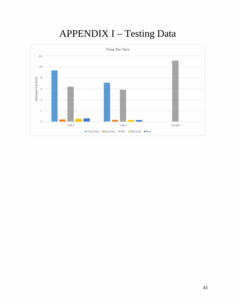
TRIAL 1 Raw Weight (lbs) 3.6Finished Product Weight (lbs) 0.441% Yield 12%
Hours Minutes Seconds minutes per partTotal Time (Hour:Min:Sec) 2 39 8 9.360784314Bandsaw 7 4 0.415686275CNC Prep 24 5 1.416666667First Run (ruined) 10 32 0.619607843Rest of CNC 1 38 9 5.773529412Disk Sand 9 7 0.53627451Intermediate Times 2 53 0.169607843
3 7 0.1833333333 14 0.190196078
57 0.055882353Total Intermediate Time 10 11 0.599019608Total CNC Time 1 48 41 6.393137255
Number of Parts Produced 17Scraped Parts 7
Time Per Part (minutes) 9.4
Predicted parts in 8hr shift 51.1
39
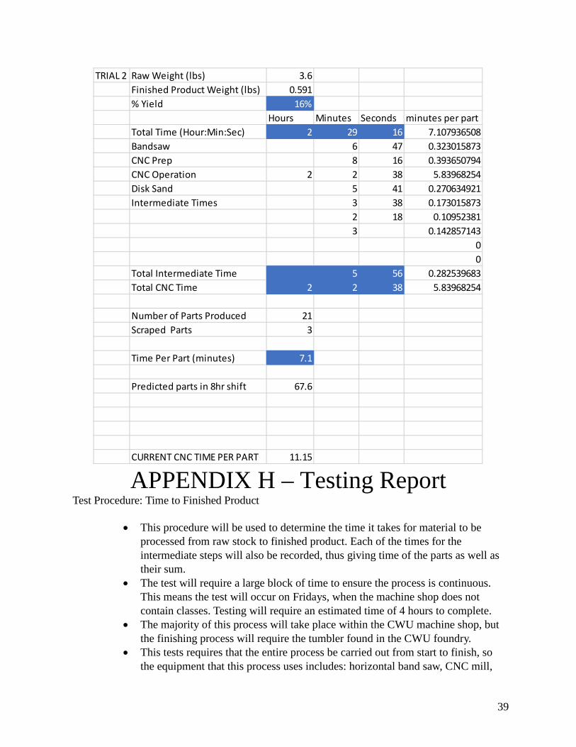
APPENDIX H – Testing Report Test Procedure: Time to Finished Product
• This procedure will be used to determine the time it takes for material to be processed from raw stock to finished product. Each of the times for the intermediate steps will also be recorded, thus giving time of the parts as well as their sum.
• The test will require a large block of time to ensure the process is continuous. This means the test will occur on Fridays, when the machine shop does not contain classes. Testing will require an estimated time of 4 hours to complete.
• The majority of this process will take place within the CWU machine shop, but the finishing process will require the tumbler found in the CWU foundry.
• This tests requires that the entire process be carried out from start to finish, so the equipment that this process uses includes: horizontal band saw, CNC mill,
TRIAL 2 Raw Weight (lbs) 3.6Finished Product Weight (lbs) 0.591% Yield 16%
Hours Minutes Seconds minutes per partTotal Time (Hour:Min:Sec) 2 29 16 7.107936508Bandsaw 6 47 0.323015873CNC Prep 8 16 0.393650794CNC Operation 2 2 38 5.83968254Disk Sand 5 41 0.270634921Intermediate Times 3 38 0.173015873
2 18 0.109523813 0.142857143
00
Total Intermediate Time 5 56 0.282539683Total CNC Time 2 2 38 5.83968254
Number of Parts Produced 21Scraped Parts 3
Time Per Part (minutes) 7.1
Predicted parts in 8hr shift 67.6
CURRENT CNC TIME PER PART 11.15
40
disk sander, and a tumbler. In addition, the testing requires that times be recorded, so a phone with a timer with lap function will be used.
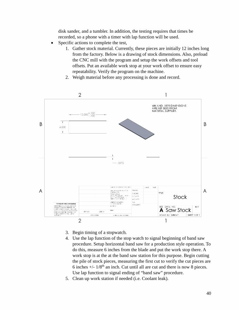
• Specific actions to complete the test, 1. Gather stock material. Currently, these pieces are initially 12 inches long
from the factory. Below is a drawing of stock dimensions. Also, preload the CNC mill with the program and setup the work offsets and tool offsets. Put an available work stop at your work offset to ensure easy repeatability. Verify the program on the machine.
2. Weigh material before any processing is done and record.
3. Begin timing of a stopwatch. 4. Use the lap function of the stop watch to signal beginning of band saw
procedure. Setup horizontal band saw for a production style operation. To do this, measure 6 inches from the blade and put the work stop there. A work stop is at the at the band saw station for this purpose. Begin cutting the pile of stock pieces, measuring the first cut to verify the cut pieces are 6 inches +/- 1/8th an inch. Cut until all are cut and there is now 8 pieces. Use lap function to signal ending of “band saw” procedure.
5. Clean up work station if needed (i.e. Coolant leak).
41
6. Bring material to the CNC mill. Use lap function of stopwatch to signal beginning of CNC process. Put first piece into the vise in the machine, lined up with the work stop set up earlier. Start slow as a safety precaution, and speed up as confidence increases. This is best practice on the first run, as some errors in height offsets are hard to catch in the verification of a program. Run the cycle until stock is depleted. Use lap function to signal end of CNC process.
7. Break out the bottle openers by hand and go to the grinding room inside the machine shop. Use the lap function to signal the start of disk sanding. Carefully sand off the tabs, being sure not to sand into the net part. Once all the tabs have been removed, use the lap function to signal the end of the sanding process.
8. Bring the bottle openers to the tumbler in the foundry room to be finished. Ensure medium, in this case it is about half inch sized smooth rocks, is in the tumbler and set the timer, a small knob near the bottom of the machine, to 2.5 hours, and the “intensity” knob to about 45. End the time of the stopwatch to signal the end of the entire process. Testing process is outlined below.
9. Once bottle openers are finished, weigh the mass of completed, accepted, parts and record. This will be compared to their unprocessed weight.
42
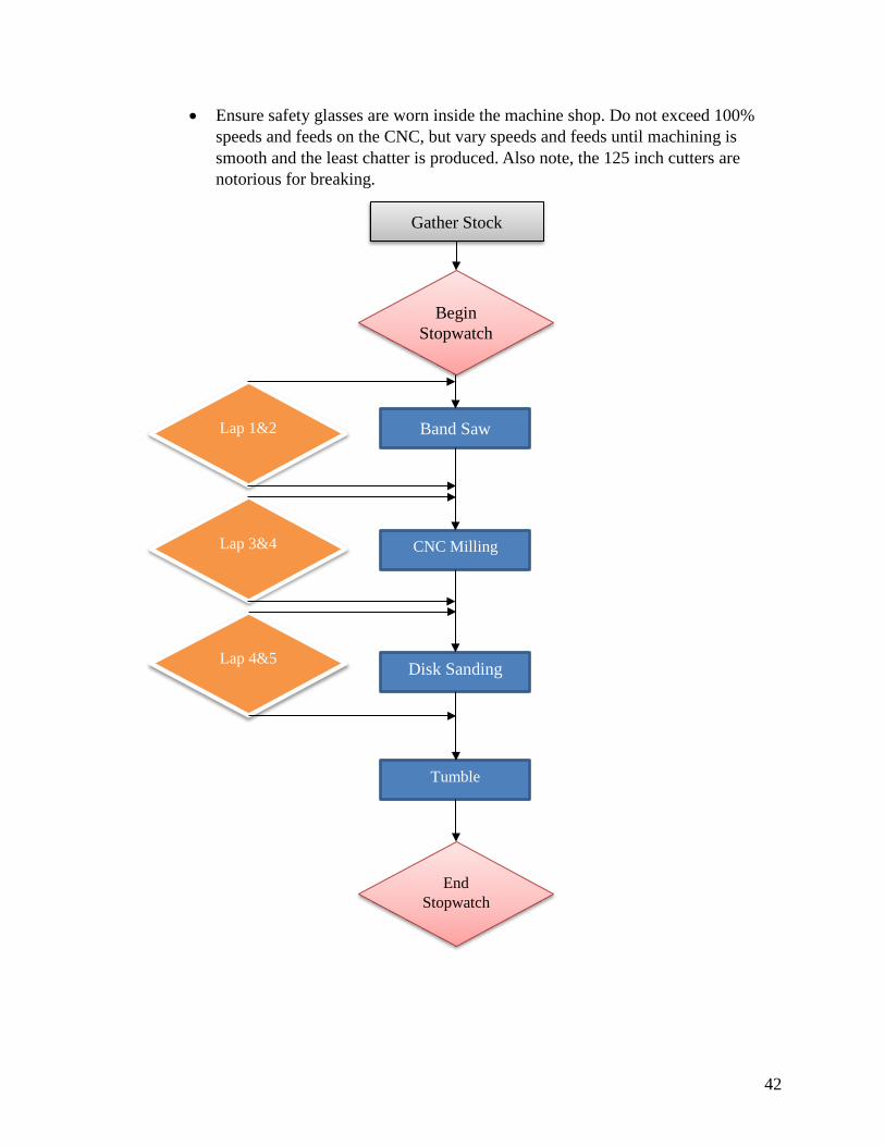
• Ensure safety glasses are worn inside the machine shop. Do not exceed 100% speeds and feeds on the CNC, but vary speeds and feeds until machining is smooth and the least chatter is produced. Also note, the 125 inch cutters are notorious for breaking.
Gather Stock
Begin Stopwatch
Lap 1&2 Band Saw
CNC Milling
Disk Sanding
Tumble
Lap 3&4
Lap 4&5
End Stopwatch
43
APPENDIX I – Testing Data

44
APPENDIX J – Resume Austin M Sanford 7409 148th St E
Puyallup, Wa. 98375 (253) 677-9192
[email protected] OBJECTIVE: To obtain an entry-level position in the field of mechanical
engineering, allowing me to utilize my education and employment experience while, gaining valuable work experience in a team-oriented environment. Seeking an opportunity to use my hands-on experiences to enhance my abilities as an engineer.
EDUCATION: • Rogers High School – Puyallup, Wa – High School Diploma – June 2015 • Pierce Community College – Puyallup, Wa – Associates of Arts – June 2015 • Central Washington University –Ellensburg, Wa.
• September 2015 – Current. Anticipated Graduation – June 2018 • Bachelor of Science in Mechanical Engineering Technology • GPA: 3.9
• Future Student of University of Washington – Fall 2018 – Master of Science in Mechanical Engineering
SKILLS & QUALIFICATIONS: • Certified SolidWorks Associate • Capable in AutoCAD, MS Office, and CAM Software • Experience in CNC machining • Classes taken include: Thermodynamics, Heat Transfer, Energy Systems,
Statics, Applied Strengths of Materials, Fluid Dynamics, Advanced Machining, Programmable Logic Controllers, Finite Element Analysis, Linear Algebra, Calculus 1-4, Differential Equations, Discrete Math
WORK EXPERIENCE: Woodland Trade Company – Tacoma, Wa Summers 2012- Current Machinist / Fiberglass Tool Maker / CNC Programmer • Involved in every process of manufacturing aerospace tools • Used CAM software to program CNC machines and manage materials • Setup CNC machines and operate them • Assist in fiberglass lay-ups • Finish and prepare product for shipping
Commercial Hardware & Specialities – Lakewood, Wa Summer 2017
• Fabricate hollow metal doors and frames
Personal Experience • Taken online third-party C++ course

45
• Volunteer at high school manufacturing program • Assisting in undergraduate research • Rebuilt classic car
References available upon request