Embed Size (px)
Citation preview
Cut-off
H1~H28
KTKF Lateral side screw clamp toolholder H8
KTKFS (For sub spindle tooling) Lateral side screw clamp toolholder H10
KGD Integral Toolholder H15
KGD-S Separate Toolholder H17
KGM (For automatic lathe) Integral Toolholder H20
KGM Integral Toolholder H20
KGM-T Integral Toolholder H21
KTKB-SS / KTKB-S Blade H24
KTKTB / KTKTBF Toolblock H25
KTKH-S Integral Toolholder H26
Recommended Cutt ing Conditions H27
Product Lineup H2
Guide for Cut-Off H3
Summary of Cut-Off H4~H5
Cut-Off Toolholders (for small diameter cut-off) H6~H11
Cut-Off Toolholders (for 2-edge insert) H12~H17
Cut-Off Toolholders (for 2-edge insert) Grooving / Plunge & Turn H18~H22
Cut-Off Toolholders (for 1-edge insert) Cut-Off H23~H26
Technical Information H27
Alternative Toolholder Reference
H2
Cut
-off
H
Product Lineup
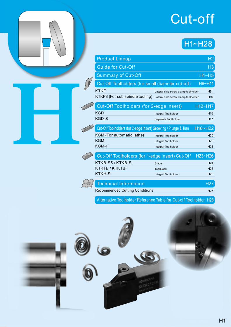
¢ Cut-Off ToolsSeries Name Shape Advantage Applications
For Small Diameter Cut-Off
1) Insert clamp is side screw type from lateral side
2) 2-edge insert
3) Max. Cutting Dia.: f 16
1) For cut-off and grooving of small workpieces
2) For automatic lathe, small machine
KGD
1) Insert is clamped from top side
2) 1-edge and 2-edge inserts available
3) Integral type and separate type are available.
4) Max. Cutting Dia.: f 50
1) PM Chipbreaker … For Cut-Off2) PH Chipbreaker … For Cut-Off (High Feed Rate)
For Grooving3) PG Chipbreaker … For Cut-Off (for automatic lathe)
Sharp-Cutting Oriented4) PF Chipbreaker … For Cut-Off (for automatic lathe)
Low feed5) PQ Chipbreaker … For Cut-Off (for automatic lathe)
Medium feed
CERACUT Plunge&Turn
1) Insert is clamped from top side
2) 1-edge and 2-edge inserts available
3) Max. Cutting Dia.: f 60
1) For cut-off and grooving of small workpieces
2) For automatic lathe, small machine
3) TMR-Chipbreaker provides stable chip control up to high feed rate ranges.
CERACUT Cut-Off
1) Self-Clamping System Tap the insert lightly with a plastic hammer to set it in the pocket.
2) 1-edge insert
3) Blade type and Integral Shank type
4) Max. Cutting Dia.: f 120
1) For cut-off and deep grooving
2) Standard chipbreaker is general cut-off type.
Feed rate: over 0.1mm/rev
P-Chipbreaker is for cut-off at low feed rates
Feed rate: 0.03~0.08mm/rev
¢ Product Lineup
For Small Diameter Cut-Off
Long Shankfor automatic lathe
Cut-Off Dia.
f 5~f 12~f 16
KTKF ( H8) KTKFS ( H10)
For sub spindle tooling
Cut-Off Dia.
f 6~f 12f 14~f 16
Width: 0.5~2.0mm Width: 1.0~2.0mm
KGDBolt ClampCut-Off Dia.
f 12~f 50
KGD ( H15) KGD-S ( H17)
Width: 1.3~4.0mm Width: 2.0~4.0mm
CERACUT Plunge&Turn
(2-edge)
Bolt ClampCut-Off Dia.
f 18~f 60
KGM ( H20) KGM-T ( H21)
Width: 1.5~4.0mm, 3~8mm Width: 2.0~6.0mm
CERACUT Cut-Off(1-edge)
Toolholder TypeCut-Off Dia.
f 30~f 79
KTKH-S ( H26) KTKB-S(S) ( H24)
Blade typeCut-Off Dia.
f 32~f 120
Width: 2.2~5.1mm Width: 1.6~9.6mm
H3
Cut
-off
H
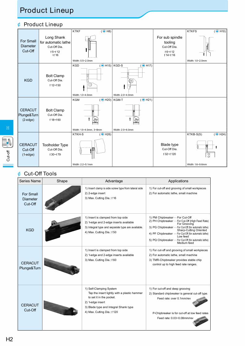
Guide for Cut-Off
Bigger boss
Sharp Corner Lead angleFig.2Fig. 1
¢ Tool Selection
¢ How to select cut-off inserts with/without lead angle (including sharp edge)
For Small Diameter Cut-Off KGD CERACUT
Plunge&TurnCERACUT
Cut-Off
Insert
1. Insert's Edge Number - - - ¡1-edge Insert…For Larger Dia. Workpiece (Max. f 120)2-edge Insert… For Smaller Dia. Workpiece
Cost per corner is reduced ¡ ¡ ¡ -
2. Use a neutral angle insert if there is no limit to the finished shape.TKF...S
TKF...NBTKFS...S
GDMGDMS GMM TKN
3. Use an angled insert to reduce the size of the remaining boss. TKF...DRGDM-&
GDMS-R-6D( Fig. 2)
GMM-&( Fig. 2)
TK&( Fig. 1)
4. Use a sharp-cornered lead-angled insert to make the remaining boss much smaller when machining small parts and thin parts. TKF...DR - GMM-&
( Fig. 2) -
5. Use the minimum width insert suitable for the machining. ¡ ¡ ¡ ¡
Toolholder
1. Use a suitable toolholder (blade) for the workpiece dia. ¡ ¡ ¡ ¡2. Use a more rigid toolholder (blade). ¡ ¡ ¡ ¡3. Use a back clamp toolholder if there is no space for clamping tools
from top side (automatic lathe). ¡ - - -
WorkpieceCut
ting
Edg
e H
eigh
t
Fig.3
1. Use a neutral angle insert if there is no limit to the nished shape.2. Use an angled insert to reduce the size of the remaining boss.3. Use a sharp-cornered lead-angled insert to make the remaining boss much smaller when machining small parts and thin parts.
¢ Caution1. Set the cutting edge height 0.1-0.2mm above the center height. (Fig.3)2. Be sure to perform wet processing. Apply enough coolant to the cutting edge.3. Keep a constant rate during processing so that optimum product life will be achieved.4. Cut off as close to the chuck as possible.5. Lower the feed rate to 1/2 to 1/3 at the near center to prevent impact caused by cutting.l Overuse of insert and toolholder (blade) may cause insert breakage and toolholder (blade)
damage.l Do not rework the insert and toolholder (blade) to prevent damage.l Clean the insert pocket well with compressed air when replacing insert.
Han
d of
Lea
d A
ngle
N(No Hand)
R(Right-hand)
L(Left-hand)
θ θ
· Angled (q) insert can reduce the burr size when cutting off.· When using a larger lead angle (q), cutting force becomes smaller, but the feed rate should be reduced.
Right-handLead Neutral
Exam
ple: S
olid W
orkpie
ceEx
ample
: Holl
ow W
orkp
iece
(Pipe
)
H4
Cut
-off
H
Summary of Cut-Off
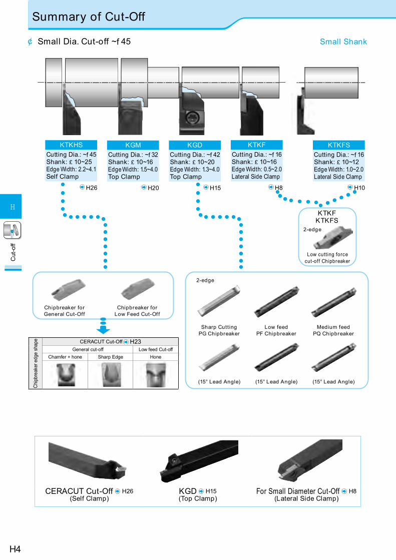
¢ Small Dia. Cut-off ~f 45 Small Shank
KGMCutting Dia.: ~f 32Shank: £ 10~16Edge Width: 1.5~4.0Top Clamp H20
KGDCutting Dia.: ~f 42Shank: £ 10~20Edge Width: 1.3~4.0Top Clamp H15
KTKFCutting Dia.: ~f 16Shank: £ 10~16Edge Width: 0.5~2.0Lateral Side Clamp H8
KTKFSCutting Dia.: ~f 16Shank: £ 10~12Edge Width: 1.0~2.0Lateral Side Clamp H10
Chip
brea
ker e
dge
shap
e CERACUT Cut-Off H23General cut-off Low feed Cut-off
Chamfer + hone Sharp Edge Hone
CERACUT Cut-Off H26(Self Clamp)
KGD H15(Top Clamp)
For Small Diameter Cut-Off H8(Lateral Side Clamp)
KTKHSCutting Dia.: ~f 45Shank: £ 10~25Edge Width: 2.2~4.1Self Clamp H26
Chipbreaker for General Cut-Off
Chipbreaker for Low Feed Cut-Of f
Low cutt ing force cut-off Chipbreaker
2-edge
2-edge
KTKFKTKFS
Sharp Cutt ingPG Chipbreaker
Low feedPF Chipbreaker
Medium feedPQ Chipbreaker
(15° Lead Angle) (15° Lead Angle) (15° Lead Angle)
H5
Cut
-off
H
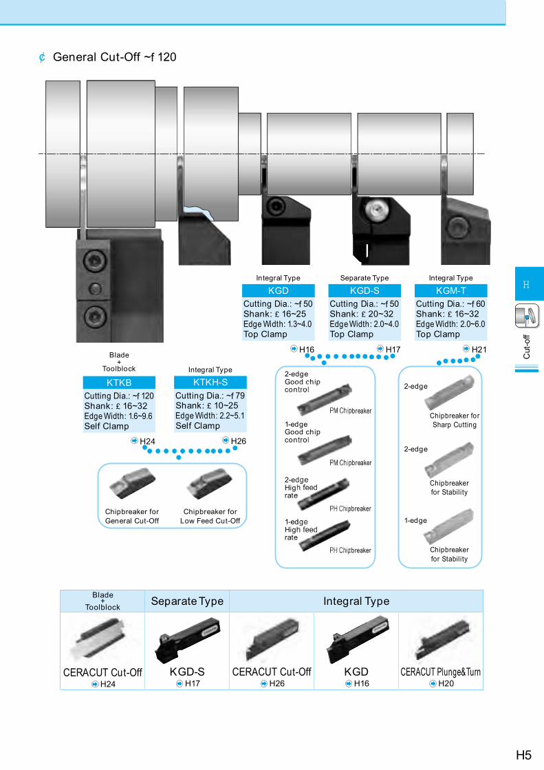
Blade+
Toolblock Separate Type Integral Type
CERACUT Cut-OffH24
KGD-SH17
CERACUT Cut-OffH26
KGDH16
CERACUT Plunge&TurnH20
¢ General Cut-Off ~f 120
Blade+
Toolblock
KTKBCutting Dia.: ~f 120Shank: £ 16~32Edge Width: 1.6~9.6Self Clamp
H24
Integral Type
KTKH-SCutting Dia.: ~f 79Shank: £ 10~25Edge Width: 2.2~5.1Self Clamp
H26
Integral Type
KGDCutting Dia.: ~f 50Shank: £ 16~25Edge Width: 1.3~4.0Top Clamp
H16
Separate Type
KGD-SCutting Dia.: ~f 50Shank: £ 20~32Edge Width: 2.0~4.0Top Clamp
H17
Integral Type
KGM-TCutting Dia.: ~f 60Shank: £ 16~32Edge Width: 2.0~6.0Top Clamp
H21
2-edge
Chipbreaker for Sharp Cutting
2-edge
Chipbreaker for Stability
Chipbreaker for Stability
Chipbreaker for Low Feed Cut-Off
Chipbreaker for General Cut-Off 1-edge
2-edge Good chip con
breaker
pbreaker
PH Chipbreaker
PH Chipbreaker
1-edge Good chip con
2-ed Hig rate
1-ed High rate
H6
Cut
-off
H
Classification of usage P Carbon Steel / Alloy Steel Q
Ref. P
age
fo
r App
licab
le To
olho
lder
s
: Continuous-Light Interruption / 1st Choice : Continuous-Light Interruption / 2nd Choice
N : Continuous / 1st ChoiceO : Continuous / 2nd Choice
M Stainless Steel Q
K Cast Iron Q
N Non-ferrous Metals Q
Insert
Handed Insert shows Right-hand
DescriptionDimension (mm) Angle
(°)MEGACOAT
MEGACOAT NANOPVD
Coated Carbide Carbide
W f Dmax re T H f d q
PR1425 PR1225 PR1025 KW10
R L R L R L R L
Right lead angle
TKF12& 050-S-16DR 0.5 5
0.03 3 8.7 5 16°
N N N N N N N N
H8
070-S-16DR 0.7 8 N N N N N N N N100-S-16DR 1.0
12
N N N N N N N N125-S-16DR 1.25 N N N N150-S-16DR 1.5 N N N N N N N N200-S-16DR 2.0 N N N N N N N N
TKF12& 050-S 0.5 5
0.03 3 8.7 5 0°
N N N N N N N N070-S 0.7 8 N N N N N N N N100-S 1.0
12
N N N N N N N N125-S 1.25 N N N N150-S 1.5 N N N N N N N N200-S 2.0 N N N N N N N N
Right lead angle Tough Edge
TKF12& 100-T-16DR 1.0
12 0.08 3 8.7 5 16°
N N N N
150-T-16DR 1.5 N N N N
200-T-16DR 2.0 N N N N
Tough Edge
TKF12& 100-T 1.0
12 0.08 3 8.7 5 0°
N N N N
150-T 1.5 N N N N
200-T 2.0 N N N N
Right lead angle
TKF12& 050-NB-20DR 0.5 5
0 3 8.7 5 20°
N N N N N N070-NB-20DR 0.7 8 N N N N N N100-NB-20DR 1.0
12N N N N N N
150-NB-20DR 1.5 N N N N N N200-NB-20DR 2.0 N N N N N N
Without Chipbreaker
TKF12& 050-NB 0.5 5
0 3 8.7 5 0°
N N N N N N070-NB 0.7 8 N N N N N N100-NB 1.0
12N N N N N N
150-NB 1.5 N N N N N N200-NB 2.0 N N N N N N
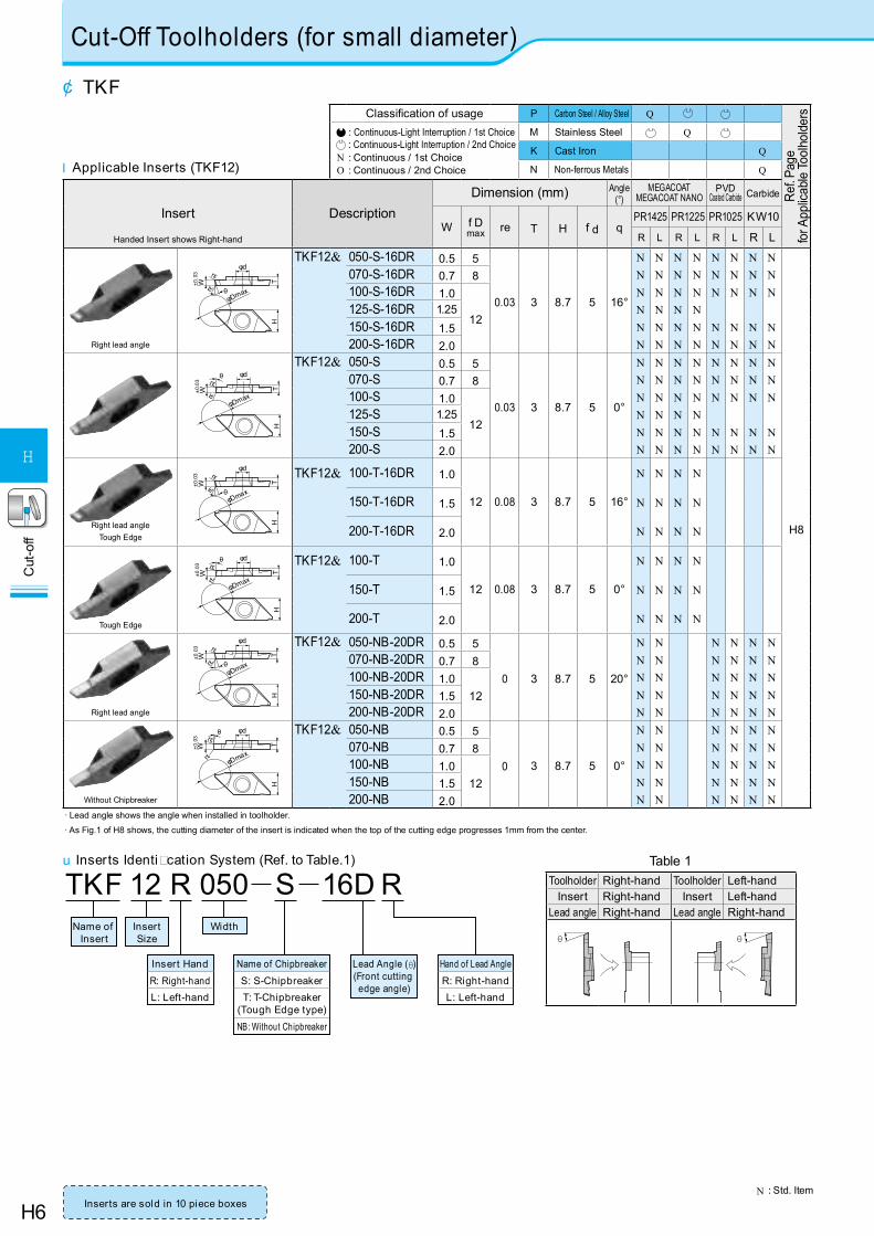
· Lead angle shows the angle when installed in toolholder.
· As Fig.1 of H8 shows, the cutting diameter of the insert is indicated when the top of the cutting edge progresses 1mm from the center.
Cut-Off Toolholders (for small diameter)
¢ TKF
N : Std. Item
H
φDmax
±0.0
3 rε
rε θ
W Tφd
H
φDmax
rε
rεW T
θ φd
±0.0
3
H
φDmax
±0.0
3 rε
rε θ
W T
φd
H
φDmaxrεW T
φdrε
θ
±0.0
3
l Applicable Inserts (TKF12)
u Inserts Identi cation System (Ref. to Table.1)
TKF R050 S 16D12 RName of
Insert
Lead Angle (θ)(Front cutting edge angle)
InsertSize
Width
Insert HandR: Right-handL: Left-hand
Name of ChipbreakerS: S-ChipbreakerT: T-Chipbreaker
(Tough Edge type)NB: Without Chipbreaker
Hand of Lead AngleR: Right-handL: Left-hand
Inserts are sold in 10 piece boxes
H
φDmax
±0.0
3 rε
rε θ
W T
φd
H
φDmax
rε
rεW T
θ φd
±0.0
3
Table 1Toolholder Right-hand Toolholder Left-hand
Insert Right-hand Insert Left-handLead angle Right-hand Lead angle Right-hand
θ θ
H7
Cut
-off
H
Inserts are sold in 10 piece boxes
Classification of usage P Carbon Steel / Alloy Steel Q
Ref. P
age
fo
r App
licab
le To
olho
lder
s
: Continuous-Light Interruption / 1st Choice : Continuous-Light Interruption / 2nd Choice
N : Continuous / 1st ChoiceO : Continuous / 2nd Choice
M Stainless Steel Q
K Cast Iron Q
N Non-ferrous Metals Q
Insert
Handed Insert shows Right-hand
DescriptionDimension (mm) Angle
(°)MEGACOAT
MEGACOAT NANOPVD
Coated Carbide Carbide
W f Dmax re T H f d q
PR1425 PR1225 PR1025 KW10
R L R L R L R L
Right lead angle
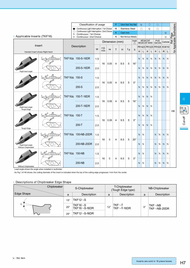
TKF16& 150-S-16DR 1.5
16 0.05 4 9.5 5 16°
N N N N N N N N
H8
200-S-16DR 2.0 N N N N N N N N
TKF16& 150-S 1.5
16 0.05 4 9.5 5 0°
N N N N N N N N
200-S 2.0 N N N N N N N N
Right lead angle Tough Edge
TKF16& 150-T-16DR 1.5
16 0.08 4 9.5 5 16°
N N N N
200-T-16DR 2.0 N N N N
Tough Edge
TKF16& 150-T 1.5
16 0.08 4 9.5 5 0°
N N N N
200-T 2.0 N N N N
Right lead angle Without Chipbreaker
TKF16& 150-NB-20DR 1.5
16 0 4 9.5 5 20°
N N N N N N
200-NB-20DR 2.0 N N N N N N
Without Chipbreaker
TKF16& 150-NB 1.5
16 0 4 9.5 5 0°
N N N N N N
200-NB 2.0 N N N N N N
· Lead angle shows the angle when installed in toolholder.
· As Fig.1 of H8 shows, the cutting diameter of the insert is indicated when the top of the cutting edge progresses 1mm from the center.
H
φDmax
±0.0
3 rε
rε θ
W T
φd
H
φDmaxrε
±0.0
3 rε
W T
φdθ
H
φDmaxrε±0
.03 rε
W T
φdθ
H
φDmaxrε
±0.0
3 rε
W T
φd
θ
l Applicable Inserts (TKF16)
N : Std. Item
H
φDmax
±0.0
3 rε
rε θ
W T
φd
H
φDmaxrε
±0.0
3 rε
W T
φdθ
Chipbreaker
Edge Shape
S-Chipbreaker T-Chipbreaker(Tough Edge type) NB-Chipbreaker
a Description a Description a Description
15° TKF12··-S
12°TKF··-TTKF··-T-16DR 0° TKF··-NB
TKF··-NB-20DR20°TKF16··-STKF16··-S-16DR
25° TKF12··-S-16DR
l Descriptions of Chipbreaker Edge Shape
α

H8
Cut
-off
H
Cut-Off Toolholders (for small diameter)
¢ KTKF (For small diameter cut-off)
N : Std. Item
2˚ 1˚
L2 2
h
L1
H1
φDmax
F1 B
1˚
F1 F2
T T
* Clamp Screw can be operated from both front and back side.
*
KTKF& 1010JX-..only for above shape
KTKF& 2020..only for above shape
KTKF& 1616JX-..(F2=10mm)KTKF& 2020JX-..(F2=12mm)only for above shape
l Right-hand shown Right-hand Insert for Right-hand Toolholder.
Fig. 1
Recommended Cutting Conditions H27
φ D1
Main Spindle
1
Fig.1(When the edge is at the center)
Fig.2(When the edge is 1mm beyond the center)
1) When using Main Spindle only Workpiece maximum f D1 (Fig.1)=f Dmax Even if the cutting edge runs beyond the center line, the insert does not contact the workpiece, since the workpiece falls off.( The clearance between the insert and the workpiece is 0.2mm)
¢ How to Use
l Left-hand shown Left-hand Insert for Left-hand Toolholder.
Fig.2
<Goose-neck Holder>
KTKFL1620JX-12 shows above gure.
L1
T
BH
1H
1 hF1 T F1
8
1°
1°
l Toolholder Dimensions
Description
Std. Dimension (mm)
Dra
win
g
Spare Parts
Applicable Inserts
H6, H7
Clamp Screw Wrench
R L H1=h B L1 L2 F1 T
KTKF& 1010JX-12 N N 10 10
120
15 10
6
Fig. 1
SB-4590TRWN LTW-10S TKF12& …1212JX-12 N N 12 12
-12
1616JX-12 N N 16 16 162020JX-12 N N 20 20 20
KTKF& 1010JX-16 N N 10 10
120
20 10
8 SB-4590TRWN LTW-10S TKF16& …1212JX-16 N N 12 12
-12
1616JX-16 N N 16 16 162020JX-16 N N 20 20 20
KTKF& 1212F-12 N N12 12 85 - 12
6SB-4590TRWN LTW-10S
TKF12& …
1212F-16 N N 8 TKF16& …
KTKFL 1216JX-12 N 12 16120 -
166 Fig.2 SB-4590TRWN LTW-10S TKF12L …
1620JX-12 N 16 20 20· Dimension T shows the distance from the Toolholder to the cutting edge. H6, H7 for the actual cutting diameter.
Note: Cutting diameter of -12 type toolholder ( f Dmax ) depends on the insert grooving width.
NEW
NEW
H9
Cut
-off
H
N : Std. Item
Main Spindle Sub Spindle
φ D2
1
Fig.3(When the edge is at the center)
Fig.4(When the edge is 1mm beyond the center)
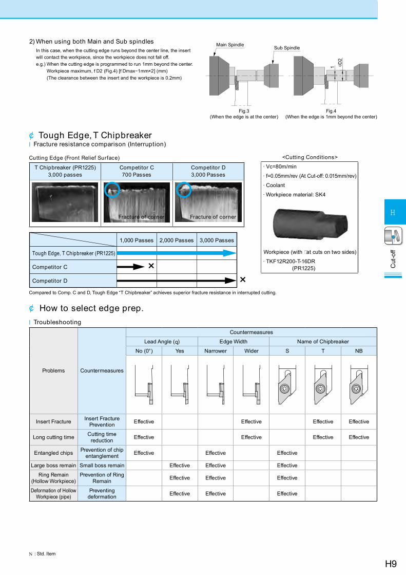
2) When using both Main and Sub spindlesIn this case, when the cutting edge runs beyond the center line, the insert will contact the workpiece, since the workpiece does not fall off.e.g.) When the cutting edge is programmed to run 1mm beyond the center.
Workpiece maximum, f D2 (Fig.4) [f Dmax−1mm×2] (mm) (The clearance between the insert and the workpiece is 0.2mm)
¢ Tough Edge, T Chipbreakerl Fracture resistance comparison (Interruption)
Cutting Edge (Front Relief Surface)
T Chipbreaker (PR1225) 3,000 passes
Competitor C700 Passes
Competitor D3,000 Passes
Tough Edge, T Chipbreaker (PR1225)
Competitor C
Competitor D
1,000 Passes
××
2,000 Passes 3,000 Passes
Compared to Comp. C and D, Tough Edge “T Chipbreaker” achieves superior fracture resistance in interrupted cutting.
¢ How to select edge prep.l Troubleshooting
Problems Countermeasures
Countermeasures
Lead Angle (q) Edge Width Name of Chipbreaker
No (0°) Yes Narrower Wider S T NB
Insert Fracture Insert Fracture Prevention Effective Effective Effective Effective
Long cutting time Cutting time reduction Effective Effective Effective Effective
Entangled chips Prevention of chip entanglement Effective Effective Effective
Large boss remain Small boss remain Effective Effective Effective
Ring Remain(Hollow Workpiece)
Prevention of Ring Remain Effective Effective Effective
Deformation of Hollow Workpiece (pipe)
Preventing deformation Effective Effective Effective
Fracture of cornerFracture of corner
<Cutting Conditions>
· Vc=80m/min
· f= 0.05mm/rev (At Cut-off: 0.015mm/rev)
· Coolant
· Workpiece material: SK4
Workpiece (with at cuts on two sides)
· TKF12R200-T-16DR(PR1225)
H10
Cut
-off
H
l Toolholder Dimensions
Description
Std.Cut-Off
Dia.Dimension (mm)
Spare PartsApplicable
InsertsH11
Clamp Screw Wrench
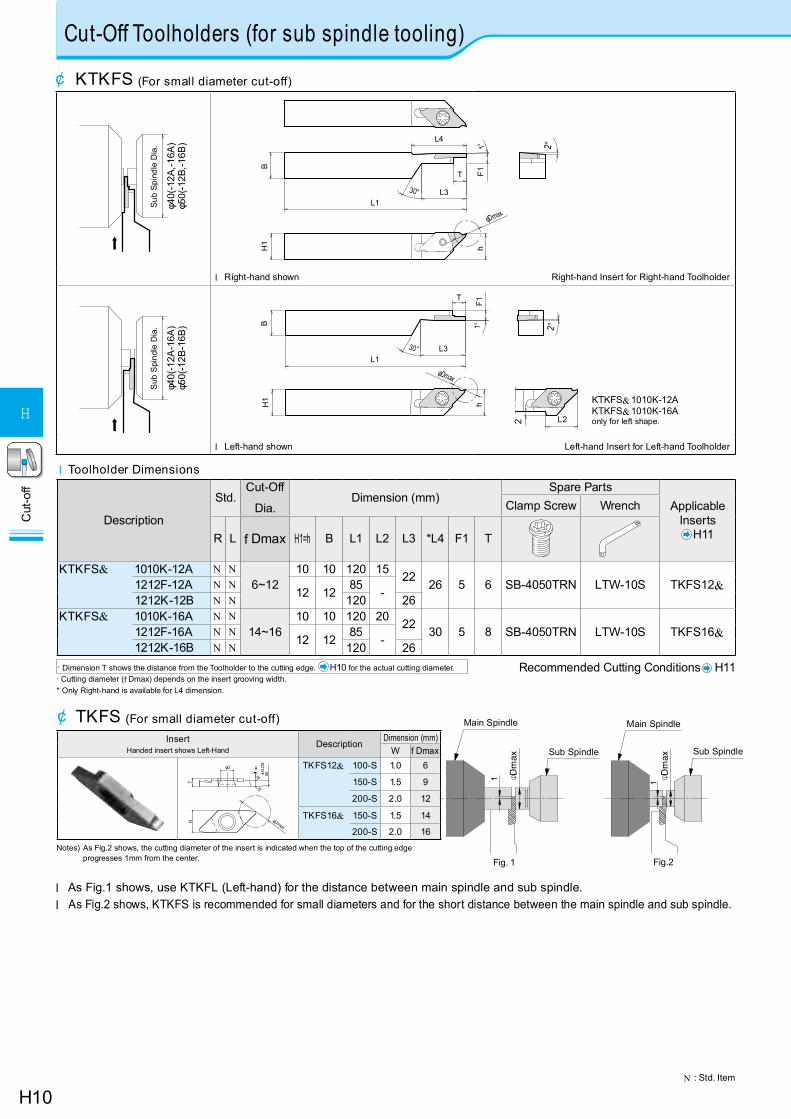
R L f Dmax H1=h B L1 L2 L3 *L4 F1 T
KTKFS& 1010K-12A N N6~12
10 10 120 15 22 26 5 6 SB-4050TRN LTW-10S TKFS12&1212F-12A N N12 12 85 -1212K-12B N N 120 26
KTKFS& 1010K-16A N N14~16
10 10 120 20 22 30 5 8 SB-4050TRN LTW-10S TKFS16&1212F-16A N N12 12 85 -1212K-16B N N 120 26
· Dimension T shows the distance from the Toolholder to the cutting edge. H10 for the actual cutting diameter. Recommended Cutting Conditions H11· Cutting diameter (f Dmax) depends on the insert grooving width.* Only Right-hand is available for L4 dimension.
N : Std. Item
Cut-Off Toolholders (for sub spindle tooling)
l As Fig.1 shows, use KTKFL (Left-hand) for the distance between main spindle and sub spindle.l As Fig.2 shows, KTKFS is recommended for small diameters and for the short distance between the main spindle and sub spindle.
¢ KTKFS (For small diameter cut-off)
¢ TKFS (For small diameter cut-off)
φ40(
-12A
,-16A
)φ5
0(-1
2B,-1
6B)
Sub
Spin
dle
Dia
.
h
φDmax
L4
L1L3
T F1
2°
BH
1
30°
1°
l Right-hand shown Right-hand Insert for Right-hand Toolholder
φ40(
-12A
-16A
)φ5
0(-1
2B-1
6B)
Sub
Spi
ndle
Dia
.
h
φDmax
T
2
L1L3
F1
2°1°BH
1
L2
30°
KTKFS&1010K-12AKTKFS&1010K-16A only for left shape.
l Left-hand shown Left-hand Insert for Left-hand Toolholder
InsertHanded insert shows Left-Hand
DescriptionDimension (mm)
W f Dmax
±0.
03θφd
T
W
H φDmax
rε
rε
TKFS12& 100-S 1.0 6
150-S 1.5 9
200-S 2.0 12
TKFS16& 150-S 1.5 14
200-S 2.0 16
Notes) As Fig.2 shows, the cutting diameter of the insert is indicated when the top of the cutting edge progresses 1mm from the center.
1 φ Dm
ax
Main Spindle
Sub Spindle
1
Main Spindle
φ Dm
ax
Sub Spindle
Fig. 1 Fig.2
H11
Cut
-off
H
Insert Description
Dimension (mm) Angle(°)
MEGACOATMEGACOAT NANO
PVD Coated Carbide Carbide
W f Dmax re T H f d q PR
1425
PR12
25
PR10
25
KW
10
Handed insert shows Left-Hand R L R L R L R L
T
W±0.0
3
H
φd
φDmax
rε
rε
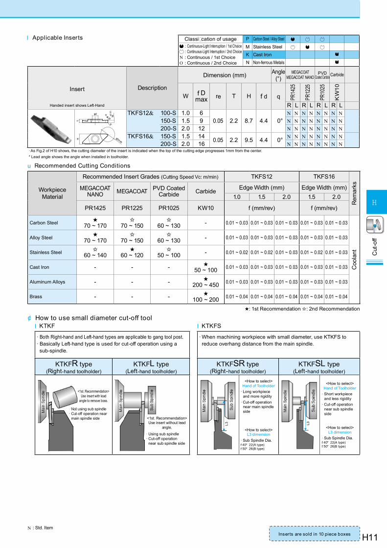
θ TKFS12& 100-S 1.0 60.05 2.2 8.7 4.4 0°
N N N N N N N N150-S 1.5 9 N N N N N N N N200-S 2.0 12 N N N N N N N N
TKFS16& 150-S 1.5 14 0.05 2.2 9.5 4.4 0° N N N N N N N N200-S 2.0 16 N N N N N N N N
· As Fig.2 of H10 shows, the cutting diameter of the insert is indicated when the top of the cutting edge progresses 1mm from the center.* Lead angle shows the angle when installed in toolholder.
N : Std. Item
u Recommended Cutting Conditions
Workpiece Material
Recommended Insert Grades (Cutting Speed Vc: m/min) TKFS12 TKFS16
Rem
arksMEGACOAT
NANO MEGACOAT PVD Coated Carbide Carbide Edge Width (mm) Edge Width (mm)
1.0 1.5 2.0 1.5 2.0
PR1425 PR1225 PR1025 KW10 f (mm/rev) f (mm/rev)
Carbon Steel ★70 ~ 170
✩70 ~ 150
✩60 ~ 130 - 0.01 ~ 0.03 0.01 ~ 0.03 0.01 ~ 0.03 0.01 ~ 0.03 0.01 ~ 0.03
Coo
lant
Alloy Steel ★70 ~ 170
✩70 ~ 150
✩60 ~ 130 - 0.01 ~ 0.03 0.01 ~ 0.03 0.01 ~ 0.03 0.01 ~ 0.03 0.01 ~ 0.03
Stainless Steel ✩60 ~ 140
★60 ~ 120
✩50 ~ 100 - 0.01 ~ 0.02 0.01 ~ 0.02 0.01 ~ 0.03 0.01 ~ 0.02 0.01 ~ 0.03
Cast Iron - - - ★50 ~ 100 0.01 ~ 0.03 0.01 ~ 0.03 0.01 ~ 0.03 0.01 ~ 0.03 0.01 ~ 0.03
Aluminum Alloys - - - ★200 ~ 450 0.01 ~ 0.03 0.01 ~ 0.03 0.01 ~ 0.03 0.01 ~ 0.03 0.01 ~ 0.03
Brass - - - ★100 ~ 200 0.01 ~ 0.04 0.01 ~ 0.04 0.01 ~ 0.04 0.01 ~ 0.04 0.01 ~ 0.04
★: 1st Recommendation ✩: 2nd Recommendation
Classi cation of usage P Carbon Steel / Alloy Steel : Continuous-Light Interruption / 1st Choice : Continuous-Light Interruption / 2nd Choice
N : Continuous / 1st ChoiceO : Continuous / 2nd Choice
M Stainless Steel
K Cast Iron
N Non-ferrous Metals
l Applicable Inserts
¢ How to use small diameter cut-off tooll KTKF l KTKFS
· Both Right-hand and Left-hand types are applicable to gang tool post.· Basically Left-hand type is used for cut-off operation using a sub-spindle.
· When machining workpiece with small diameter, use KTKFS to reduce overhang distance from the main spindle.
KTKFR type (Right-hand toolholder)
KTKFL type (Left-hand toolholder)
KTKFSR type (Right-hand toolholder)
KTKFSL type (Left-hand toolholder)
<1st. Recommendation>Use insert with lead
angle to remove boss.
· Not using sub spindle· Cut-off operation near
main spindle side
<1st. Recommendation>Use insert without lead
angle.
· Using sub spindle· Cut-off operation
near sub spindle side
L3
<How to select>Hand of Toolholder
· Long workpiece and more rigidity
· Cut-off operation near main spindle side
<How to select>L3 dimension
· Sub Spindle Dia.f 40" 22(A type)f 50" 26(B type)
L3
<How to select>Hand of Toolholder
· Short workpiece and less rigidity
· Cut-off operation near sub spindle side
<How to select>L3 dimension
· Sub Spindle Dia.f 40" 22(A type)f 50" 26(B type)
Inserts are sold in 10 piece boxes
H12
Cut
-off
H
Classification of usage P Carbon Steel / Alloy Steel Q P
Ref. P
age f
or A
pplic
able
Toolh
older
s
: Continuous-Light Interruption / 1st Choice : Continuous-Light Interruption / 2nd Choice
N : Continuous / 1st ChoiceO : Continuous / 2nd Choice
M Stainless Steel Q P
N Non-ferrous Metals Q
Insert Description
Dimension (mm) Angle (°) MEGACOAT Carbide
Wre M L H q
PR
1225
PR
1215
GW
15
ToleranceHanded Insert shows Right-hand
Cut
-off
Low feed2-edge
±0.0
4
L
2.5 °
2 .5°W
M rεrε
H
GDM 1316N-003PF1.3
±0.04
0.031.0
16 3.7
-
N N
H151316N-015PF 0.15 N N
1516N-003PF1.5
0.031.2
N N
1516N-015PF 0.15 N N
2020N-003PF 2.0
0.03
1.7
20 4.3
N N H15H16H17
2520N-003PF 2.5 2.1 N N
3020N-003PF 3.0 2.3 N N
15° Lead AngleLow feed 2-edge
±0.0
4
L
M2.5 °
2 .5 °W rε
θ°
H
GDM 1316& -003PF-15D 1.3
±0.04 0.03
1.016 3.7
15°
N NH15
1516& -003PF-15D 1.5 1.2 N N
2020& -003PF-15D 2.0 1.7
20 4.3
N N
H15H16H17
2520& -003PF-15D 2.5 2.1 N N
3020& -003PF-15D 3.0 2.3 N N
Medium feed2-edge
±0.0
3
L
3°3°W
M rε
rε
H
GDM 2020N-010PQ 2.0
±0.03 0.1
1.7
20 4.3 -
N N
2520N-010PQ 2.5 2.1 N N
3020N-010PQ 3.0 2.3 N N
15° Lead AngleMedium feed
2-edge
±0.0
3
L
3°3°W rε
θ°
M
H
GDM 2020R-010PQ-15D 2.0
±0.03 0.1
1.7
20 4.3 15°
N N
2520R-010PQ-15D 2.5 2.1 N N
3020R-010PQ-15D 3.0 2.3 N N
Low cutting force2-edge
L
3°W
M
3°
rε
rε
H
±0.0
2
GDG 2020N-005PG 2.0
±0.02 0.05
1.7
20 4.3 -
N
2520N-005PG 2.5 2.1 N
3020N-005PG 3.0 2.3 N
15° Lead AngleLow cutting force
2-edge
L
3°3°W
±0.0
2
θ°
H
rε
M
GDG 2020R-005PG-15D 2.0
±0.02 0.05
1.7
20 4.3 15°
N
2520R-005PG-15D 2.5 2.1 N
3020R-005PG-15D 3.0 2.3 N
Note) 1. Using the PF/PM chipbreaker (for cut-off) for grooving cannot create a flat bottom (Ref. to the right figure).
¢ GDM/GDG
Cut-Off Inserts
Groove bottom created by PF/PM chipbreaker
H13
Cut
-off
H
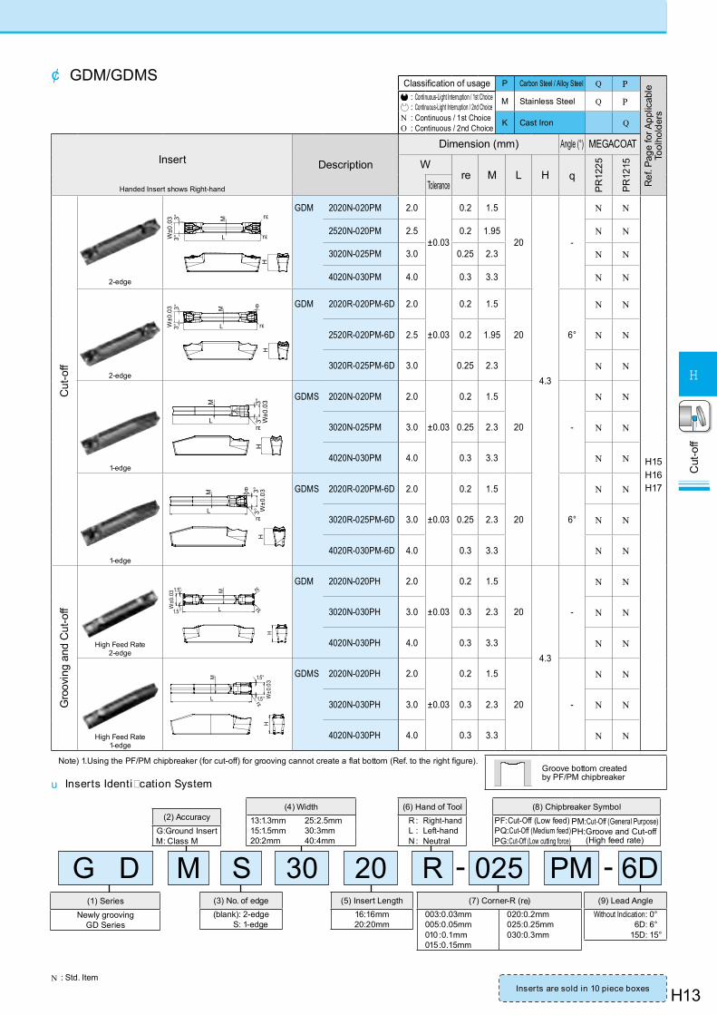
Classification of usage P Carbon Steel / Alloy Steel Q P
Ref
. Pag
e fo
r App
licab
le
Tool
hold
ers
: Continuous-Light Interruption / 1st Choice : Continuous-Light Interruption / 2nd Choice
N : Continuous / 1st ChoiceO : Continuous / 2nd Choice
M Stainless Steel Q P
K Cast Iron Q
Insert Description
Dimension (mm) Angle (°) MEGACOAT
Wre M L H q
PR
1225
PR
1215
ToleranceHanded Insert shows Right-hand
Cut
-off
2-edge
H
3°3°W
±0.0
3
L
M rε
rε
GDM 2020N-020PM 2.0
±0.03
0.2 1.5
20
4.3
-
N N
H15H16H17
2520N-020PM 2.5 0.2 1.95 N N
3020N-025PM 3.0 0.25 2.3 N N
4020N-030PM 4.0 0.3 3.3 N N
2-edge
H
L
M
rε
3°3°W
±0.0
3 θ GDM 2020R-020PM-6D 2.0
±0.03
0.2 1.5
20 6°
N N
2520R-020PM-6D 2.5 0.2 1.95 N N
3020R-025PM-6D 3.0 0.25 2.3 N N
1-edge
H
rεL
M
3°3°
W±0
.03 GDMS 2020N-020PM 2.0
±0.03
0.2 1.5
20 -
N N
3020N-025PM 3.0 0.25 2.3 N N
4020N-030PM 4.0 0.3 3.3 N N
1-edge
H
L
M
rε
θ
3°3°
W±0
.03 GDMS 2020R-020PM-6D 2.0
±0.03
0.2 1.5
20 6°
N N
3020R-025PM-6D 3.0 0.25 2.3 N N
4020R-030PM-6D 4.0 0.3 3.3 N N
Gro
ovin
g an
d C
ut-o
ff
High Feed Rate2-edge
H
L
M rε
rεW±0
.031.5°
1.5°
GDM 2020N-020PH 2.0
±0.03
0.2 1.5
20
4.3
-
N N
3020N-030PH 3.0 0.3 2.3 N N
4020N-030PH 4.0 0.3 3.3 N N
High Feed Rate1-edge
M
L W±0
.031.5°
1.5°
H
rε
GDMS 2020N-020PH 2.0
±0.03
0.2 1.5
20 -
N N
3020N-030PH 3.0 0.3 2.3 N N
4020N-030PH 4.0 0.3 3.3 N N
Note) 1.Using the PF/PM chipbreaker (for cut-off) for grooving cannot create a flat bottom (Ref. to the right figure).
¢ GDM/GDMS
Groove bottom created by PF/PM chipbreaker
(3) No. of edge(blank): 2-edge
S: 1-edge
(5) Insert Length16:16mm20:20mm
(7) Corner-R (re)003:0.03mm005:0.05mm010 :0.1mm015:0.15mm
020:0.2mm025:0.25mm030:0.3mm
(2) AccuracyG:Ground InsertM: Class M
(4) Width13:1.3mm 25:2.5mm15:1.5mm 30:3mm20:2mm 40:4mm
(6) Hand of ToolR : Right-handL : Left-handN : Neutral
G D M 30 6DPM-(1) Series
Newly groovingGD Series
-S 20 R 025
(8) Chipbreaker SymbolPF:Cut-Off (Low feed)PQ:Cut-Off (Medium feed)PG:Cut-Off (Low cutting force)
PM:Cut-Off (General Purpose)PH: Groove and Cut-off
(High feed rate)
(9) Lead AngleWithout Indication: 0°
6D: 6°15D: 15°
u Inserts Identi cation System
N : Std. ItemInserts are sold in 10 piece boxes
H14
Cut
-off
H
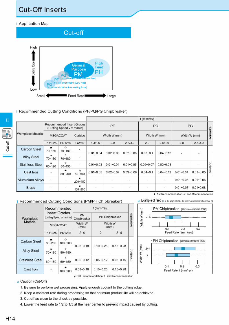
Cut-off
V
l Application Map
l Recommended Cutting Conditions (PM/PH Chipbreaker)
Workpiece Material
Recommended Insert Grades
(Cutting Speed Vc: m/min)
f (mm/rev)
Rem
arksPM
Chipbreaker PH Chipbreaker
MEGACOAT Width W(mm)
Width W(mm)
PR1225 PR1215 2~4 2 3~4
Carbon Steel ★ 80~200
✩ 100~200
0.08~0.18 0.10~0.25 0.15~0.28
Coo
lantAlloy Steel ★
70~180✩
80~180
Stainless Steel ★ 60~150
✩ 60~150 0.06~0.12 0.05~0.12 0.08~0.15
Cast Iron - ★ 100~200 0.08~0.18 0.10~0.25 0.15~0.28
★: 1st Recommendation ✩: 2nd Recommendation
u Caution (Cut-Off)
1. Be sure to perform wet processing. Apply enough coolant to the cutting edge.2. Keep a constant rate during processing so that optimum product life will be achieved.3. Cut off as close to the chuck as possible. 4. Lower the feed rate to 1/2 to 1/3 at the near center to prevent impact caused by cutting.
3~4
2
0.1 0.2 0.3
· PH Chipbreaker
Feed Rate f (mm/rev)
[Workpiece material: S50C]
Wid
th W
(mm
)
2~4
0.1 0.2 0.3Feed Rate f (mm/rev)
· [Workpiece material: S50C]PM Chipbreaker
Wid
th W
(mm
)
u Example of feed
GeneraPurposePM
High
Low
Cuttin
g forc
e
LargeSmall Feed Rate
omatic lathe (Medium feed) omatic lathe (Medium feed)
omatic lathe (Low feed) omatic lathe (Low feed)
omatic lathe (Low cutting force) omatic lathe (Low cutting force)
[¢ in the graph indicates the most recommended value of feed (f)]
Cut-Off Inserts
l Recommended Cutting Conditions (PF/PQ/PG Chipbreaker)
f (mm/rev)
Workpiece Material
Recommended Insert Grades(Cutting Speed Vc: m/min) PF PQ PG
Rem
arks
MEGACOAT Carbide Width W (mm) Width W (mm) Width W (mm)
PR1225 PR1215 GW15 1.3/1.5 2.0 2.5/3.0 2.0 2.5/3.0 2.0 2.5/3.0
Carbon Steel ★70~150
✩70~180 -
0.01~0.04 0.02~0.06 0.02~0.08 0.03~0.1 0.04~0.12 - -
Coo
lant
Alloy Steel ★70~150
✩70~180 -
Stainless Steel ★60~120
✩60~150 - 0.01~0.03 0.01~0.04 0.01~0.05 0.02~0.07 0.02~0.08 - -
Cast Iron - ★80~200
✩50~100 0.01~0.05 0.02~0.07 0.03~0.08 0.04~0.1 0.04~0.12 0.01~0.04 0.01~0.05
Aluminium Alloys - - ★200~450 - - - - - 0.01~0.05 0.01~0.06
Brass - - ★100~200 - - - - - 0.01~0.07 0.01~0.08
★: 1st Recommendation ✩: 2nd Recommendation
H15
Cut
-off
H
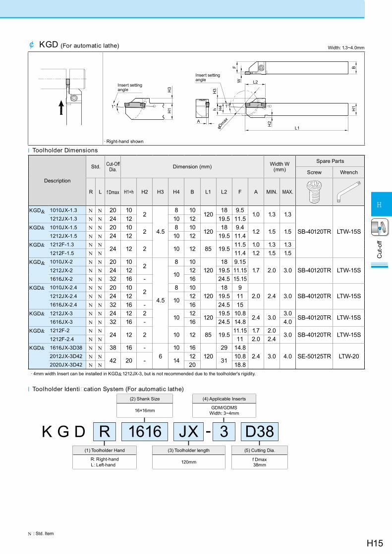
(3) Toolholder length
120mm
(5) Cutting Dia.
f Dmax38mm
(2) Shank Size
16×16mm
K G D R JX -(1) Toolholder Hand
R: Right-handL: Left-hand
(4) Applicable Inserts
GDM/GDMSWidth: 3~4mm
1616 3 D38
l Toolholder Identi cation System (For automatic lathe)
¢ KGD (For automatic lathe)
Insert setting angle
φDmax
H3
H1
H3
H4
H2
H1
B
h
WF
A
L2
L1
1°1°
Insert setting angle
l Toolholder Dimensions
Description
Std. Cut-Off Dia. Dimension (mm) Width W
(mm)Spare Parts
Screw Wrench
R L f Dmax H1=h H2 H3 H4 B L1 L2 F A MIN. MAX.
KGD& 1010JX-1.3 N N 20 102
4.5
8 10120
18 9.5 1.0 1.3 1.3
SB-40120TR LTW-15S
1212JX-1.3 N N 24 12 10 12 19.5 11.5 KGD& 1010JX-1.5 N N 20 10
28 10
12018 9.4
1.2 1.5 1.51212JX-1.5 N N 24 12 10 12 19.5 11.4
KGD& 1212F-1.3 N N24 12 2 10 12 85 19.5
11.5 1.0 1.3 1.31212F-1.5 N N 11.4 1.2 1.5 1.5
KGD& 1010JX-2 N N 20 102
4.5
8 10120
18 9.151.7 2.0 3.0 SB-40120TR LTW-15S1212JX-2 N N 24 12
1012 19.5 11.15
1616JX-2 N N 32 16 - 16 24.5 15.15KGD& 1010JX-2.4 N N 20 10
28 10
12018 9
2.0 2.4 3.0 SB-40120TR LTW-15S1212JX-2.4 N N 24 1210
12 19.5 111616JX-2.4 N N 32 16 - 16 24.5 15
KGD& 1212JX-3 N N 24 12 210
12120
19.5 10.82.4 3.0
3.0SB-40120TR LTW-15S
1616JX-3 N N 32 16 - 16 24.5 14.8 4.0KGD& 1212F-2 N N
24 12 2 10 12 85 19.511.15 1.7 2.0
3.0 SB-40120TR LTW-15S1212F-2.4 N N 11 2.0 2.4
KGD& 1616JX-3D38 N N 38 16 -6
10 16120
29 14.82.4 3.0 4.0 SE-50125TR LTW-202012JX-3D42 N N
42 20 - 1412
3110.8
2020JX-3D42 N N 20 18.8· 4mm width Insert can be installed in KGD&1212JX-3, but is not recommended due to the toolholder's rigidity.
· Right-hand shown
N : Std. Item
Width: 1.3~4.0mm
H16
Cut
-off
H
Grooving / Cut-Off
N : Std. Item
¢ KGD (Integral Type)
L3
H2
H3
W
L1
A
F1
T
L2
h
BH
1
l Toolholder Dimensions
Wid
th (m
m)
Max
. dep
th o
f cut
(mm
)
Description
Std. Dimension (mm) Width W (mm)
Spare Parts
Clamp Bolt Wrench
R L H1=h H2 H3 B L1 L2 L3 F1 A T MIN. MAX.
2
6KGD& 1616H-2T06 N N 16 4.0
9.5
16 100 27.7 28.0 15.2
1.7
6
2.0 3.0
HH5X16
LW-4
2020K-2T06 N N 20-
20 12528.0 -
19.22525M-2T06 N N 25 25 150 24.2 HH5X25
10KGD& 1616H-2T10 N N 16 4.0 16 100 30.2 30.5 15.2
10HH5X16
2020K-2T10 N N 20-
20 12530.5 -
19.22525M-2T10 N N 25 25 150 24.2 HH5X25
17
KGD& 1616H-2T17 N N 16 4.0 16 100 31.2 31.5 15.2
17HH5X162012K-2T17 N N
20-
12 12532.5 -
11.22020K-2T17 N N 20 125 19.22525M-2T17 N N 25 25 150 24.2 HH5X25
2.4 17KGD& 2012K-2.4T17 N N
20 -12 125
32.5 -11.0
2.0 17 2.4 3.0 HH5X16 LW-42020K-2.4T17 N N 20 125 19.0
3
6KGD& 1616H-3T06 N N 16 4.0 16 100 27.7 28.0 14.8
2.4
6
3.0 4.0
HH5X16
LW-4
2020K-3T06 N N 20-
20 12528.0 -
18.8 2525M-3T06 N N 25 25 150 23.8 HH5X25
10KGD& 1616H-3T10 N N 16 4.0 16 100 30.2 30.5 14.8
10HH5X16
2020K-3T10 N N 20-
20 12530.5 -
18.8 2525M-3T10 N N 25 25 150 23.8 HH5X25
20
KGD& 1616H-3T20 N N 16 4.0 16 100 34.2 34.5 14.8
20HH5X162012K-3T20 N N
20-
12 12534.5
-10.8
2020K-3T20 N N 20 125 18.8 2525M-3T20 N N 25 25 150 35.5 23.8 HH5X25
4
10KGD& 2020K-4T10 N N 20
-
20 12530.5
-
18.3
3.4
10
4.0 5.0
HH5X16
LW-42525M-4T10 N N 25 25 150 23.3 HH5X25
20KGD& 2020K-4T20 N N 20 20 125 34.5 18.3
20HH5X16
2525M-4T20 N N 25 25 150 35.5 23.3 HH5X25
25 KGD& 2525M-4T25 N N 25 25 150 40.5 23.3 25Note) 1. Dimension T shows the distance from the Toolholder to the cutting edge. (If the dimension T is 20 mm or more, the maximum depth of groove made by the 2-edge insert will be 18 mm.) 2. Recommended tightening torque of clamp bolt for insert: 6.5N·m (Groove width 2 - 4mm)
· Right-hand shown
Recommended Cutting Conditions H14
H17
Cut
-off
H
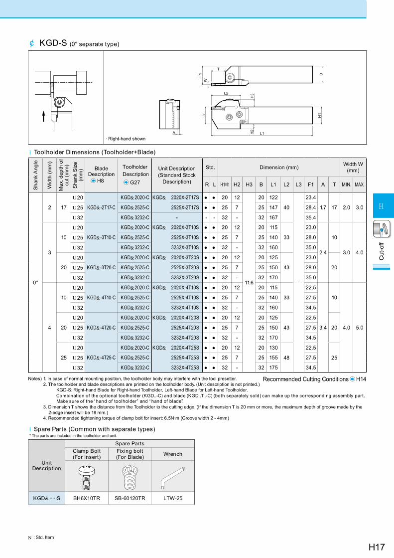
¢ KGD-S (0° separate type)
B
T
WF1
h
L2
H3
H2
L1
H1
A
· Right-hand shown
N : Std. Item
Notes) 1. In case of normal mounting position, the toolholder body may interfere with the tool presetter. 2. The toolholder and blade descriptions are printed on the toolholder body. (Unit description is not printed.)
KGD-S: Right-hand Blade for Right-hand Toolholder, Left-hand Blade for Left-hand Toolholder. Combination of the optional toolholder (KGD..-C) and blade (KGD..T..-C) (both separately sold) can make up the corresponding assembly part. Make sure of the “ hand of toolholder” and “ hand of blade”.
3. Dimension T shows the distance from the Toolholder to the cutting edge. (If the dimension T is 20 mm or more, the maximum depth of groove made by the 2-edge insert will be 18 mm.)
4. Recommended tightening torque of clamp bolt for insert: 6.5N·m (Groove width 2 - 4mm)
l Spare Parts (Common with separate types)* The parts are included in the toolholder and unit.
Unit Description
Spare PartsClamp Bolt(For insert)
Fixing bolt(For Blade) Wrench
KGD& ·····S BH6X10TR SB-60120TR LTW-25
l Toolholder Dimensions (Toolholder+Blade)
Sha
nk A
ngle
Wid
th (m
m)
Max
. dep
th o
f cu
t (m
m)
Sha
nk S
ize
(mm
) Blade Description
H8
Toolholder Description
G27
Unit Description(Standard Stock
Description)
Std. Dimension (mm) Width W (mm)
R L H1=h H2 H3 B L1 L2 L3 F1 A T MIN. MAX.
0°
2 17
U20
KGD& -2T17-C
KGD&2020-C KGD& 2020X-2T17S ● ● 20 12
11.6
20 122
40
-
23.4
1.7 17 2.0 3.0U25 KGD&2525-C 2525X-2T17S ● ● 25 7 25 147 28.4
U32 KGD&3232-C - - - 32 - 32 167 35.4
3
10
U20
KGD& -3T10-C
KGD&2020-C KGD& 2020X-3T10S ● ● 20 12 20 115
33
23.0
2.4
10
3.0 4.0
U25 KGD&2525-C 2525X-3T10S ● ● 25 7 25 140 28.0
U32 KGD&3232-C 3232X-3T10S ● ● 32 - 32 160 35.0
20
U20
KGD& -3T20-C
KGD&2020-C KGD& 2020X-3T20S ● ● 20 12 20 125
43
23.0
20U25 KGD&2525-C 2525X-3T20S ● ● 25 7 25 150 28.0
U32 KGD&3232-C 3232X-3T20S ● ● 32 - 32 170 35.0
4
10
U20
KGD& -4T10-C
KGD&2020-C KGD& 2020X-4T10S ● ● 20 12 20 115
33
22.5
3.4
10
4.0 5.0
U25 KGD&2525-C 2525X-4T10S ● ● 25 7 25 140 27.5
U32 KGD&3232-C 3232X-4T10S ● ● 32 - 32 160 34.5
20
U20
KGD& -4T20-C
KGD&2020-C KGD& 2020X-4T20S ● ● 20 12 20 125
43
22.5
20U25 KGD&2525-C 2525X-4T20S ● ● 25 7 25 150 27.5
U32 KGD&3232-C 3232X-4T20S ● ● 32 - 32 170 34.5
25
U20
KGD& -4T25-C
KGD&2020-C KGD& 2020X-4T25S ● ● 20 12 20 130
48
22.5
25U25 KGD&2525-C 2525X-4T25S ● ● 25 7 25 155 27.5
U32 KGD&3232-C 3232X-4T25S ● ● 32 - 32 175 34.5
Recommended Cutting Conditions H14
H18
Cut
-off
H
N : Std. ItemR : Std. Item (Right-hand Only)
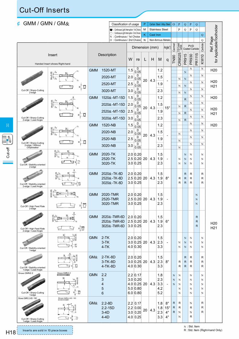
Cut-Off Inserts
Classification of usage P Carbon Steel / Alloy Steel O P Q P Q
Ref
. Pag
e fo
r App
licab
leTo
olho
lder
: Continuous-Light Interruption / 1st Choice : Continuous-Light Interruption / 2nd Choice
N : Continuous / 1st ChoiceO : Continuous / 2nd Choice
M Stainless Steel P Q P Q
K Cast Iron Q
N Non-ferrous Metals Q
Insert
Handed Insert shows Right-hand
Description
Dimension (mm) Angle(°)
Cerm
etCV
D Coat
ed Ca
rbide PVD
Coated Carbide Carb
ide
W re L H M q
TN90
CR
9025
PR91
5PR
930
PR11
15K
W10
Cut-Off / Sharp-Cutting2-edge
GMM 1520-MT 1.5 0
20 4.3
1.2
-
N N H200.05 N
2020-MT 2.0 0 1.5 N N
H20H21
0.05 N N
2520-MT 2.5 0 1.9 N N0.05 N N
3020-MT 3.0 0 2.3 N N0.05 N N
Cut-Off / Sharp-Cutting2-edge / Lead Angle
GMM 1520& -MT-15D 1.5 0
20 4.3
1.2
15°
N N H200.05 R
2020& -MT-15D 2.0 0 1.5 N N
H20H21
0.05 N R
2520& -MT-15D 2.5 0 1.9 N N0.05 N R
3020& -MT-15D 3.0 0 2.3 N N0.05 N R
Cut-Off / Sharp-Cutting2-edge / Without
Chipbreaker
GMM 1520-NB 1.5 0
20 4.3
1.2
-
N N H200.05
2020-NB 2.0 0 1.5 N N
H20H21
0.05 N
2520-NB 2.5 0 1.9 N N0.05 N
3020-NB 3.0 0 2.3 N N0.05 N
Cut-Off / Stability-oriented2-edge
GMM 2020-TK2520-TK3020-TK
2.02.53.0
0.200.200.25
20 4.31.51.92.3
- NN
NNN
NNN
NNN
Cut-Off / Stability-oriented2-edge / Lead Angle
GMM 2020& -TK-8D2520& -TK-8D3020& -TK-8D
2.02.53.0
0.200.200.25
20 4.31.51.92.3
8° RR
RRR
RRR
RRR
Cut-Off / High Feed Rate2-edge
GMM 2020-TMR2520-TMR3020-TMR
2.02.53.0
0.200.200.25
20 4.31.51.92.3
-NNN
Cut-Off / High Feed Rate2-edge / Lead Angle
GMM 2020& -TMR-6D2520& -TMR-6D3020& -TMR-6D
2.02.53.0
0.200.200.25
20 4.31.51.92.3
6°RRR
Cut-Off / Stability-oriented1-edge
GMN 2-TK3-TK4-TK
2.03.04.0
0.200.250.30
20 4.31.52.33.3
- NN
NNN
NNN
NNN
Cut-Off / Stability-oriented1-edge / Lead Angle
GM& 2-TK-8D3-TK-8D4-TK-8D
2.03.04.0
0.200.250.30
20 4.31.52.33.3
8° RR
RRR
RRR
RRR
Cut-Off / Sharp-Cutting1-edge
GMN 2.23456
2.23.04.05.06.0
0.170.200.250.800.80
20 4.3
1.82.33.34.25.2
-
NNN
NNNNN
NNNNN
NNNNN
Cut-Off / Sharp-Cutting1-edge / Lead Angle
GM& 2.2-8D2.2-15D3-4D4-4D
2.22.23.04.0
0.170.000.200.25
20 4.3
1.81.82.33.3
8°15°4°4°
RRR
RR
NN
NR
NR
RRR
L
M
W±0
.05
H
rε2°2°
θ
L
H
M
W±0
.05
rε
2°2°
θ
L
M
rε
H
W±0
.052°
2°
H
H
M
W± 0
.05
2°2°
rε
HLW
±0.0
5 2 °2°
M
rε
rε
Shows GMN2.2
Shows GMR2.2-8D / 15D
W±0
.05 2°
2 °
M
rεL
θ
H
LW±0
.05 2°
2°
M
rε
rε
H
Shows GMR2.2-8D / 15D
M
rε
W± 0
.052°
2°
L
H
θ
M
rε
Shows GMN2.2
L
W± 0
.052°
2°H
¢ GMM / GMN / GM&
Inserts are sold in 10 piece boxes
H
rε
M
W± 0
.05 2°
2° L
L
H
M
W± 0
.05 2°
2° rε
θ
H19
Cut
-off
H
TK
MT
TMR
Sharp Cutting Stability
Hig
hFe
ed R
ate
Low
TMR
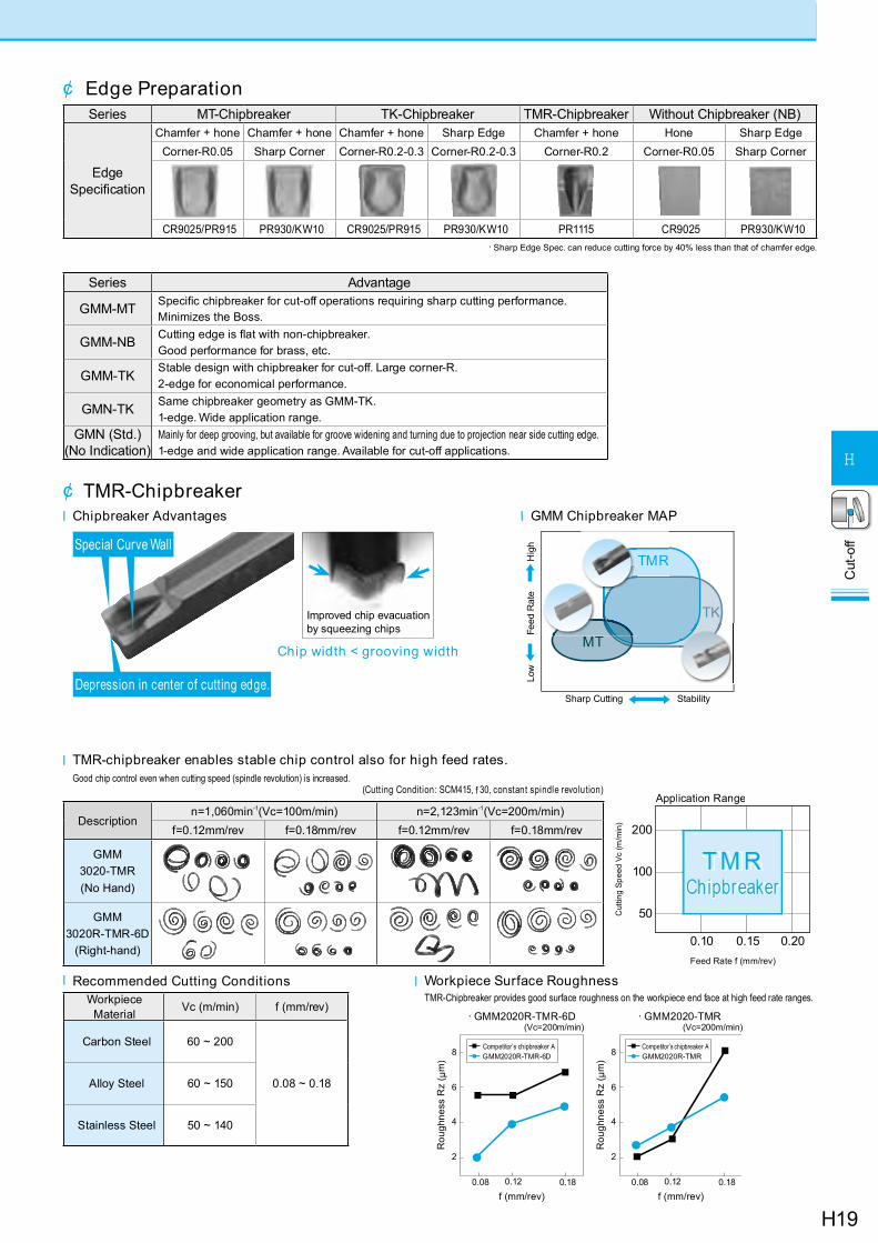
¢ Edge PreparationSeries MT-Chipbreaker TK-Chipbreaker TMR-Chipbreaker Without Chipbreaker (NB)
Edge Specification
Chamfer + hone Chamfer + hone Chamfer + hone Sharp Edge Chamfer + hone Hone Sharp EdgeCorner-R0.05 Sharp Corner Corner-R0.2-0.3 Corner-R0.2-0.3 Corner-R0.2 Corner-R0.05 Sharp Corner
CR9025/PR915 PR930/KW10 CR9025/PR915 PR930/KW10 PR1115 CR9025 PR930/KW10· Sharp Edge Spec. can reduce cutting force by 40% less than that of chamfer edge.
Series Advantage
GMM-MT Specific chipbreaker for cut-off operations requiring sharp cutting performance.Minimizes the Boss.
GMM-NB Cutting edge is flat with non-chipbreaker.Good performance for brass, etc.
GMM-TK Stable design with chipbreaker for cut-off. Large corner-R.2-edge for economical performance.
GMN-TK Same chipbreaker geometry as GMM-TK.1-edge. Wide application range.
GMN (Std.)(No Indication)
Mainly for deep grooving, but available for groove widening and turning due to projection near side cutting edge.1-edge and wide application range. Available for cut-off applications.
¢ TMR-Chipbreakerl Chipbreaker Advantages l GMM Chipbreaker MAP
l Recommended Cutting ConditionsWorkpiece
Material Vc (m/min) f (mm/rev)
Carbon Steel 60 ~ 200
0.08 ~ 0.18Alloy Steel 60 ~ 150
Stainless Steel 50 ~ 140
Descriptionn=1,060min-1(Vc=100m/min) n=2,123min-1(Vc=200m/min)
f=0.12mm/rev f=0.18mm/rev f=0.12mm/rev f=0.18mm/rev
GMM3020-TMR(No Hand)
GMM3020R-TMR-6D
(Right-hand)
(Cutting Condition: SCM415, f 30, constant spindle revolution)
l TMR-chipbreaker enables stable chip control also for high feed rates.Good chip control even when cutting speed (spindle revolution) is increased.
l Workpiece Surface RoughnessTMR-Chipbreaker provides good surface roughness on the workpiece end face at high feed rate ranges.
Chip width < grooving width
Improved chip evacuation by squeezing chips
Special Curve Wall
50
100
200
Cut
ting
Spee
d Vc
(m/m
in)
0.10 0.15 0.20Feed Rate f (mm/rev)
Application Range
0.08 0.12
2
4
0.18
6
8
Rou
ghne
ss R
z ( µ
m)
f (mm/rev)
(Vc=200m/min)
0.08 0.12
2
4
0.18
6
8
Rou
ghne
ss R
z ( µ
m)
f (mm/rev)
(Vc=200m/min)· GMM2020R-TMR-6D · GMM2020-TMR
GMM2020R-TMR-6DCompetitor’s chipbreaker A
GMM2020R-TMRCompetitor’s chipbreaker A
Depression in center of cutting edge.
H20
Cut
-off
H
Cut-Off Toolholders
H3
H1
φDmax
5°
F
KGM& 1616 A
hH
3
L2
L1
H4
H2
H1
B
W
¢ KGM (For automatic lathe)
l Right-hand shown
N : Std. Item
Width: 1.5~4.0mm
Description
Std. Cut-Off Dia. Dimension (mm) WidthW(mm)
Spare PartsScrew Wrench
R L f Dmax H1=h H2 H3 H4 B L1 L2 F A MIN. MAX.
KGM& 1010JX-1.5 N N 20 10 2 3 8 10 120 18 9.4 1.2 1.5 2.0 SE-40120TR LTW-15S1212JX-1.5 N N 25 12 4 10 12 20.5 11.4KGM& 1010JX-2 N N 20 10 2 3 8 10
12018 9.15
1.7 2.0 3.0 SE-40120TR LTW-15S1212JX-2 N N 25 12 4 10 12 19 11.151616JX-2 N N 32 16 - 9 16 24.5 15.15 SE-50125TR LTW-20
KGM& 1010JX-2.5 N N 20 10 2 3 8 10120
18 92.0 2.4 3.0 SE-40120TR LTW-15S1212JX-2.5 N N 25 12 4 10 12 20.5 11
1616JX-2.5 N N 32 16 - 9 16 25.5 15 SE-50125TR LTW-20KGM& 1616JX-3 N N 32 16 - 4 9 16 120 25.5 14.8 2.4 3.0 4.0 SE-50125TR LTW-20KGM& 1212F-1.5-85 N 25 12 2 4 10 12 85 19 11.4 1.2 1.5 2.0 SE-40120TR LTW-15SKGM& 1212F-2-85 N N 25 12 2 4 10 12 85 19 11.15 1.7 2.0 3.0 SE-40120TR LTW-15SKGM& 1212F-2.5-85 N N 25 12 2 4 10 12 85 19 11 2.0 2.4 3.0 SE-40120TR LTW-15S
l Toolholder Dimensions
L2
A
h H2
5°
WF1
T
L1
H1
H3
B¢ KGM
l Toolholder Dimensions
Width: 3.0~8.0mm
l Right-hand shown
· 4mm width Insert can be installed in KGM&1212H-3, but is not recommended due to the toolholder's rigidity. · Dimension T shows the distance from the Toolholder to the cutting edge.
Description
Std. Dimension (mm) WidthW(mm)
Spare PartsScrew Wrench
R L H1=h H2 H3 B L1 L2 F1 A T MIN. MAX.
KGM& 1212H-3 N N 12 4 6 12 10027
10.8
2.4 9
3.0 3.0 SB-5TR - LTW-20 -1616H-3 N N 16 7 16 14.8
3.0 4.0 -HH5X16
- LW-42020K-3 N N 20 - 7 20 125 18.82525M-3 N N 25 25 150 23.8 HH5X25
KGM& 2020K-4 N N 20 - 7 20 125 27 18.3 3.4 10 4.0 5.0 -HH5X16
- LW-42525M-4 N N 25 25 150 23.3 HH5X25KGM& 2020K-5 N N 20
- 720 125
2717.8
4.4 10 5.0 6.0 -HH5X16
- LW-42525M-5 N N 25 25 150 22.8HH5X253232P-5 N N 32 32 170 29.8
KGM& 2525M-8 N N 25 7.5 10.5 25 150 40 22.0 6.0 25 8.0 8.0 - HH6X25 - LW-53232P-8 N N 32 - 32 170 29.0
H21
Cut
-off
H
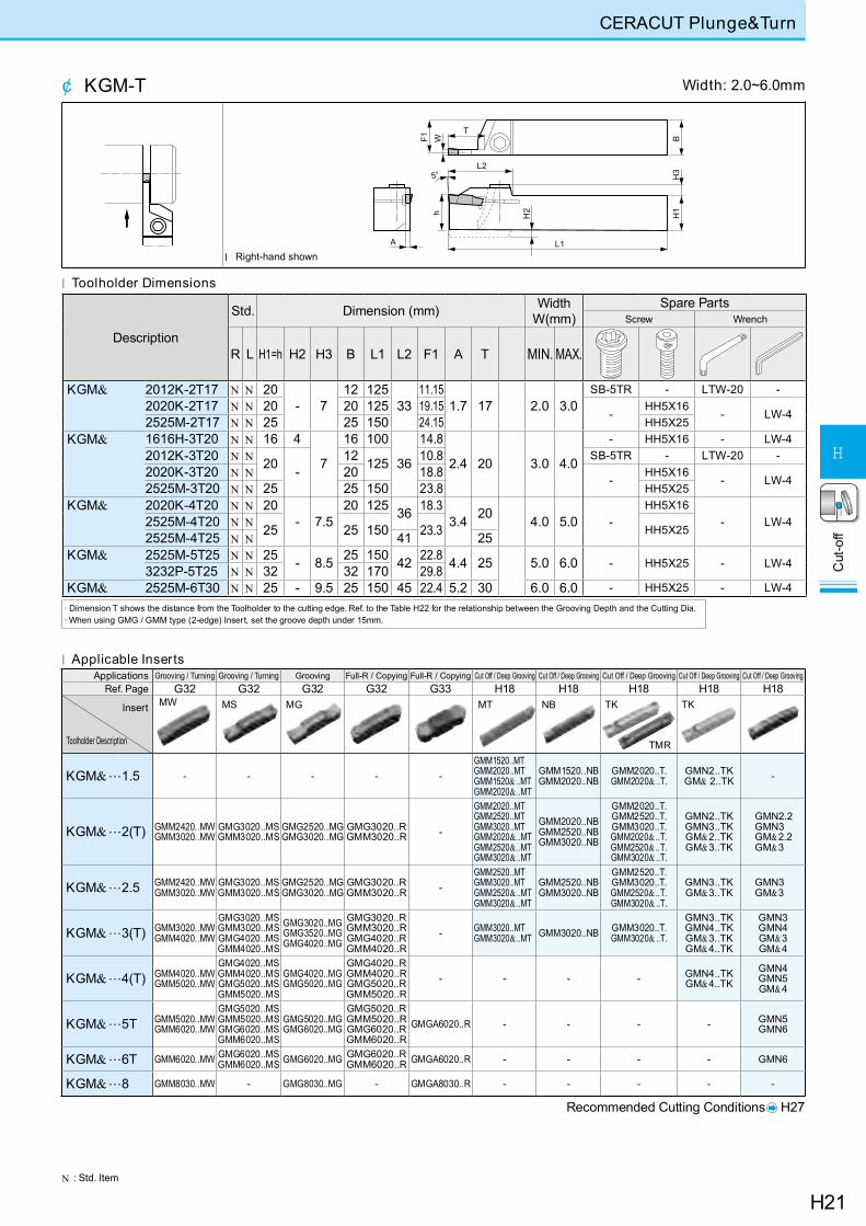
CERACUT Plunge&Turn
N : Std. Item
¢ KGM-T
h H2
A
W
5°
F1
T
L2
L1
H1
H3
B
l Toolholder Dimensions
· Dimension T shows the distance from the Toolholder to the cutting edge. Ref. to the Table H22 for the relationship between the Grooving Depth and the Cutting Dia. · When using GMG / GMM type (2-edge) Insert, set the groove depth under 15mm.
Width: 2.0~6.0mm
l Right-hand shown
Applications Grooving / Turning Grooving / Turning Grooving Full-R / Copying Full-R / Copying Cut Off / Deep Grooving Cut Off / Deep Grooving Cut Off / Deep Grooving Cut Off / Deep Grooving Cut Off / Deep GroovingRef. Page G32 G32 G32 G32 G33 H18 H18 H18 H18 H18
Insert
Toolholder Description
MW
KGM&…1.5 - - - - -GMM1520..MT GMM2020..MTGMM1520& ..MT GMM2020& ..MT
GMM1520..NBGMM2020..NB
GMM2020..T.GMM2020& ..T.
GMN2..TK GM& 2..TK -
KGM&…2(T) GMM2420..MW GMM3020..MW
GMG3020..MSGMM3020..MS
GMG2520..MG GMG3020..MG
GMG3020..R GMM3020..R -
GMM2020..MTGMM2520..MTGMM3020..MTGMM2020& ..MTGMM2520& ..MTGMM3020& ..MT
GMM2020..NBGMM2520..NBGMM3020..NB
GMM2020..T.GMM2520..T.GMM3020..T.GMM2020& ..T.GMM2520& ..T.GMM3020& ..T.
GMN2..TKGMN3..TK GM&2..TKGM&3..TK
GMN2.2GMN3GM&2.2GM&3
KGM&…2.5 GMM2420..MW GMM3020..MW
GMG3020..MSGMM3020..MS
GMG2520..MG GMG3020..MG
GMG3020..R GMM3020..R -
GMM2520..MTGMM3020..MTGMM2520& ..MTGMM3020& ..MT
GMM2520..NBGMM3020..NB
GMM2520..T.GMM3020..T.GMM2520& ..T.GMM3020& ..T.
GMN3..TK GM&3..TK
GMN3GM&3
KGM&…3(T) GMM3020..MW GMM4020..MW
GMG3020..MSGMM3020..MS GMG4020..MSGMM4020..MS
GMG3020..MG GMG3520..MG GMG4020..MG
GMG3020..R GMM3020..R GMG4020..R GMM4020..R
- GMM3020..MTGMM3020& ..MT GMM3020..NB GMM3020..T.
GMM3020& ..T.
GMN3..TKGMN4..TK GM&3..TKGM&4..TK
GMN3GMN4GM&3GM&4
KGM&…4(T) GMM4020..MW GMM5020..MW
GMG4020..MSGMM4020..MS GMG5020..MSGMM5020..MS
GMG4020..MG GMG5020..MG
GMG4020..R GMM4020..R GMG5020..R GMM5020..R
- - - - GMN4..TKGM&4..TK
GMN4GMN5GM&4
KGM&…5T GMM5020..MW GMM6020..MW
GMG5020..MSGMM5020..MS GMG6020..MSGMM6020..MS
GMG5020..MG GMG6020..MG
GMG5020..R GMM5020..R GMG6020..R GMM6020..R
GMGA6020..R - - - - GMN5GMN6
KGM&…6T GMM6020..MW GMG6020..MSGMM6020..MS GMG6020..MG GMG6020..R
GMM6020..R GMGA6020..R - - - - GMN6
KGM&…8 GMM8030..MW - GMG8030..MG - GMGA8030..R - - - - -
MGMS MT TK TKNB
TMR
Recommended Cutting Conditions H27
l Applicable Inserts
Description
Std. Dimension (mm) WidthW(mm)
Spare PartsScrew Wrench
R L H1=h H2 H3 B L1 L2 F1 A T MIN. MAX.
KGM& 2012K-2T17 N N 20- 7
12 12533
11.151.7 17 2.0 3.0
SB-5TR - LTW-20 -2020K-2T17 N N 20 20 125 19.15
-HH5X16
- LW-42525M-2T17 N N 25 25 150 24.15 HH5X25KGM& 1616H-3T20 N N 16 4
7
16 100
36
14.8
2.4 20 3.0 4.0
- HH5X16 - LW-42012K-3T20 N N 20 -
12 125 10.8 SB-5TR - LTW-20 -2020K-3T20 N N 20 18.8
-HH5X16
- LW-42525M-3T20 N N 25 25 150 23.8 HH5X25KGM& 2020K-4T20 N N 20
- 7.520 125 36 18.3
3.4 20 4.0 5.0 -HH5X16
- LW-42525M-4T20 N N 25 25 150 23.3 HH5X252525M-4T25 N N 41 25KGM& 2525M-5T25 N N 25 - 8.5 25 150 42 22.8 4.4 25 5.0 6.0 - HH5X25 - LW-43232P-5T25 N N 32 32 170 29.8KGM& 2525M-6T30 N N 25 - 9.5 25 150 45 22.4 5.2 30 6.0 6.0 - HH5X25 - LW-4
H22
Cut
-off
H
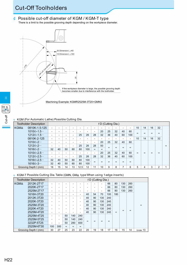
Cut-Off Toolholders
Machining Example: KGMR2525M-3T20+GMN3
φ130
φ40 ( φ
D: Cut-o
ff Dia.
)
25
18 (Dimension t, φ130)
20 (Dimension t, φ40)
If the workpiece diameter is large, the possible grooving depth becomes smaller due to interference with the toolholder.
¢ Possible cut-off diameter of KGM / KGM-T typeThere is a limit to the possible grooving depth depending on the workpiece diameter.
Toolholder Description f D (Cutting Dia.)KGM& 0810K-1.5-125 - - - - - - - - - - - - 10 14 16 32
∞
1010O-1.5··· - - - - - - - 20 25 32 40 60∞ ∞ ∞ ∞1212O-1.5··· - - - - 25 26 28 32 36 40 60 100
0810K-2-125 - - - - - - - - - - - - 10 14 16 321010O-2··· - - - - - - - 20 25 32 40 60
∞ ∞ ∞ ∞
1212O-2··· - - - - 25 26 28 50∞ ∞ ∞ ∞1616O-2··· 32 40 50 60 80 100 ∞ ∞
1010O-2.5··· - - - - - - - 20 25 32 40 601212O-2.5··· - - - - 25 26 28 32 36 40 60 1001616O-2.5··· 32 40 50 60 80 100
∞ ∞ ∞ ∞ ∞ ∞1616O-3··· 32 40 50 60 80 100Grooving Depth t (mm) 16 15 14 13 12.5 12 11 10 9 8 7 6 5 4 3 2 1
Toolholder Description f D (Cutting Dia.)KGM& 2012K-2T17 -
--
---
---
---
---
---
---
---
66 80 130 260
∞
2020K-2T17 66 80 130 2602525M-2T17 66 80 130 2601616H-3T20 - - - - - 40 54 70 100 180
∞ ∞
2012K-3T20 -----
-----
-----
-----
-----
40 90 130 240
∞
2020K-3T20 40 90 130 2402525M-3T20 40 90 130 2402020K-4T20 40 90 130 2402525M-4T20 40 90 130 2402525M-4T25 -
--
---
50 140 240
∞ ∞ ∞ ∞2525M-5T25 50 140 2403232P-5T25 50 280 6002525M-6T30 100 300 ∞ ∞ ∞
Grooving Depth t (mm) 30 27 25 23 22 20 19 18 17 16 15 14 Under 13
u KGM-T Possible Cutting Dia. Table (GMN, GM& type When using 1-edge inserts)
u KGM (For Automatic Lathe) Possible Cutting Dia.
H23
Cut
-off
H
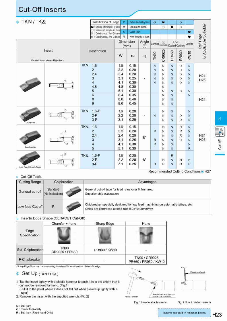
Cut-Off Inserts
N : Std. ItemO : Check Availability R : Std. Item (Right-hand Only)
u Inserts Edge Shape (CERACUT Cut-Off)
¢ TKN / TK& Classification of usage P Carbon Steel / Alloy Steel O O
Ref
. Pag
e
for A
pplic
able
Tool
hold
er : Continuous-Light Interruption / 1st Choice : Continuous-Light Interruption / 2nd Choice
N : Continuous / 1st ChoiceO : Continuous / 2nd Choice
M Stainless Steel OK Cast Iron
N Non-ferrous Metals
Insert
Handed Insert shows Right-hand
Description
Dimension (mm)
Angle(°) Cermet CVD
Coated CarbidePVD
Coated Carbide Carbide
W re q
TN90
CR
9025
PR66
0
PR93
0
KW
10
rε
rε W±0
.05
TKN 1.622.4344.85689
1.62.22.43.14.14.85.16.48.09.6
0.150.200.200.250.300.300.300.350.400.45
-
NNNNN
NNNNNNNNNN
NNNNN
NNNN
OOOOO
O
NNNNN
NN
H24H26
H24
Low Feed
rε
rε W±0
.05 TKN 1.6-P
2-P3-P
1.62.23.1
0.200.200.25
- NNNN
NNN
OO
NNN
H24H26
Lead angle
rε
θ
W±0
.05
TK& 1.6 1.6 0.15
8°
R N R N2 2.2 0.20 R N N R N2.4 2.4 0.20 N N R N3 3.1 0.25 R N N O N4 4.1 0.30 R N N N5 5.1 0.30 N N R
rε
θ
W±0
.05
TK& 1.6-P2-P3-P
1.62.23.1
0.200.200.25
8°R
RR
RNN
RR
RR
Recommended Cutting Conditions H27u Cut-Off Tools
Inserts are sold in 10 piece boxes
Cutting Range Chipbreaker Advantages
General cut-off Standard(No Indication)
General cut-off type for feed rates over 0.1mm/rev.Superior chip evacuation
Low feed Cut-off P Chipbreaker specially designed for low feed machining on automatic lathes, etc.Chips are controlled at feed rate 0.03~0.08mm/rev.
Edge Specification
Chamfer + hone Sharp Edge Hone
Std. Chipbreaker TN90CR9025 / PR660 PR930 / KW10 -
P-Chipbreaker - - TN90 / CR9025PR660 / PR930 / KW10
· Sharp Edge Spec. can reduce cutting force by 40% less than that of chamfer edge.
Low Feed / Lead-Angle
Fig. 1 How to attach inserts Fig. 2 How to detach inserts
¢ Set Up (TKN / TK& )
1. Tap the insert lightly with a plastic hammer to push it in to the extent that it can not be removed by hand. (Fig.1) (Pull it to the point where it does not fall out when picked up lightly with a nger)
2. Remove the insert with the supplied wrench. (Fig.2) Plastic HammerInsert’s back end does not contact the toolholder.
Releasing Wrench
H24
Cut
-off
H
Cut-Off Blades
7°
φD
150°A
H h
W
L
hH
W
150°
B
A
7°
φD
L
W
KTKBRKTKB
15°
15°
150°
hH
A
B
φD
A
hH
W
L
l Blade Dimensions
¢ KTKB-S / KTKB-SS
Fig. 1
Fig. 2 Fig. 3
u How to install toolblock and blade.
Datum Plane
Incorrect way
Correct way
Datum Plane
Datum Plane
Incorrect setting of clamp elementIncorrect setting of clamp element
Incor
rect
Edge
Heig
htE
dge
Hei
ght
If the clamp element is mounted backward, a large gap will occur between the clamp and the toolblock, and the blade may come off during cutting. Be careful when installing the clamp for safety.
Description Std.
Cut-Off Dia. Dimension (mm) Width
Dra
win
gApplicable Inserts H23
Applicable BlocksH25
Low Feed Lead angle Low Feed / Lead-Angle
f Dmax *H h B L A W
KTKB 19-1SS N 32 19 15.7 2.4 86 1.2 1.6 Fig. 3 TKN1.6 TKN1.6-P TK&1.6 TK&1.6-P KTKTB 16-19 20-19
KTKB 26-1SS N 35 26 21.4 2.4 110 1.2 1.6 Fig. 3 TKN1.6 TKN1.6-P TK&1.6 TK&1.6-P KTKTB 16-26 20-26
KTKB 32-1SS N 35 32 25 2.4 150 1.2 1.6 Fig.3 TKN1.6 TKN1.6-P TK&1.6 TK&1.6-P
KTKTB 20-32 25-32 32-32KTKTBF 25-32 32-32
KTKB 19-2S N 40 19 15.7 - 86 1.8 2.22.4
Fig. 1
TKN2TKN2.4 TKN2-P TK&2
TK&2.4 TK&2-P KTKTB 16-19 20-19
KTKB 26-2S N 50
26 21.4 - 110
1.8 2.22.4
TKN2TKN2.4 TKN2-P TK&2
TK&2.4 TK&2-P
KTKTB 16-26 20-26
26-3S N 75 2.6 3.1 TKN3 TKN3-P TK&3 TK&3-P26-4S N 80 3.4 4.1 TKN4 - TK&4 -26-5S N 80 4.2 4.8
5.1TKN4.8TKN5 - TK&5 -
KTKB 32-2S N 50
32 25
2.6
150
1.8 2.22.4 Fig. 2 TKN2
TKN2.4 TKN2-P TK&2TK&2.4 TK&2-P
KTKTB 20-32 25-32 32-32KTKTBF 25-32 32-32
32-3S N 100
-
2.6 3.1
Fig. 1
TKN3 TKN3-P TK&3 TK&3-P32-4S N 100 3.4 4.1 TKN4 - TK&4 -32-5S N 120 4.2 4.8
5.1TKN4.8TKN5 - TK&5 -
32-6S N 120 5.4 6.4 TKN6 - - -KTKB& 32-8S N 120 32 25 - 150 6.8 8.0 Fig. 1 TKN8 - - -
32-9S R 120 8.0 9.6 TKN9 - - -Note) 1. Suffix “-SS” means silver coating.
2. Releasing wrench is “LTK-5”.* Dimension H shows virtual apex distance.
N : Std. ItemR : Std. Item (Right-hand Only)
H25
Cut
-off
H
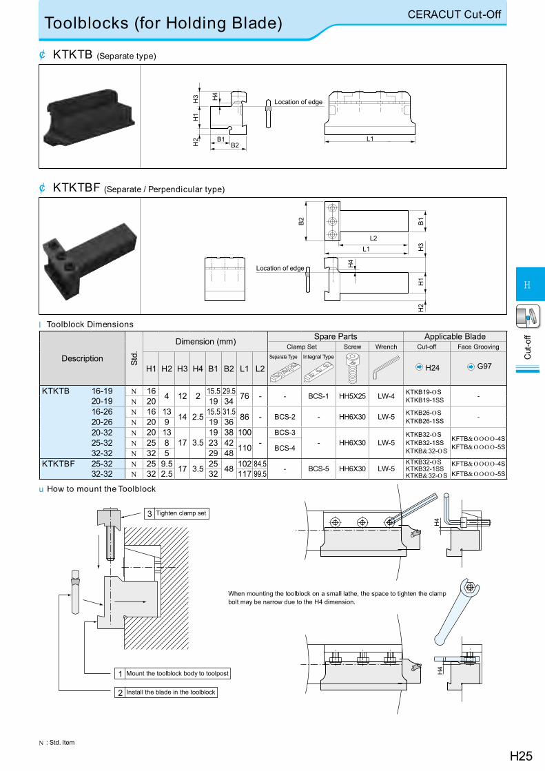
Toolblocks (for Holding Blade) CERACUT Cut-Off
N : Std. Item
l Toolblock Dimensions
¢ KTKTB (Separate type)
¢ KTKTBF (Separate / Perpendicular type)H
2H
1H
3 H4
B1B2
Location of edge
L1
L2L1
B2
H2
H1
H4
H3
B1
Location of edge
u How to mount the Toolblock
Tighten clamp set3
Mount the toolblock body to toolpost1
Install the blade in the toolblock2
When mounting the toolblock on a small lathe, the space to tighten the clamp bolt may be narrow due to the H4 dimension.
H4
H4
Description Std.
Dimension (mm) Spare Parts Applicable BladeClamp Set Screw Wrench Cut-off Face Grooving
H1 H2 H3 H4 B1 B2 L1 L2Separate Type Integral Type
H24 G97
KTKTB 16-19 N 16 4 12 2 15.5 29.5 76 - - BCS-1 HH5X25 LW-4 KTKB19-OSKTKB19-1SS -
20-19 N 20 19 3416-26 N 16 13 14 2.5 15.5 31.5 86 - BCS-2 - HH6X30 LW-5 KTKB26-OS
KTKB26-1SS -20-26 N 20 9 19 3620-32 N 20 13
17 3.519 38 100
-BCS-3
- HH6X30 LW-5KTKB32-OSKTKB32-1SSKTKB&32-OS
KFTB&OOOO -4SKFTB&OOOO -5S25-32 N 25 8 23 42 110 BCS-432-32 N 32 5 29 48
KTKTBF 25-32 N 25 9.5 17 3.5 25 48 102 84.5 - BCS-5 HH6X30 LW-5KTKB32-OSKTKB32-1SSKTKB&32-OS
KFTB&OOOO -4SKFTB&OOOO -5S32-32 N 32 2.5 32 117 99.5
H26
Cut
-off
H
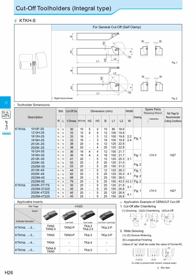
Cut-Off Toolholders (Integral type)
N : Std. Item
Description
Std. Cut-Off Dia. Dimension (mm) Width
Drawing
Spare PartsRef. Page for
Recommended Cutting Conditions
Releasing Wrench
R L f Dmax H1=h H2 H3 B L1 L2 W
KTKH& 1010F-2S1212H-2S1612H-2S1616H-2S2012K-2S2020K-2S
NNNNNN
NNNNNN
303333333838
101216162020
54----
453344
101212161220
80100100100125125
18.619.819.819.822.822.8
2.22.4 Fig. 1
LTK-5 H271612H-3S1616H-3S2012K-3S2020K-3S2525M-3S
NNN
NNN
3636415253
1616202025
44---
44555
1216122025
100100125125150
21.721.725.331.031.5
3.1Fig. 1
NN
NN
Fig. 2
2012K-4S2020K-4S2525M-4S
N N 446268
202025
---
555
122025
125125150
26.335.038.0
4.1Fig. 1
NN
NN
Fig. 2
2525M-5S N N 79 25 - 5 25 150 43.5 4.8, 5.1 Fig. 2KTKH& 2020K-3T17S
2525M-3T22SNN
NN
3545
2025
--
55
2025
125150
21.826.8 3.1
Fig. 1 LTK-5 H272020K-4T22S2525M-4T22S
NN
NN
4545
2025
--
55
2025
125150
26.826.8 4.1
(3)(1) (2) (4)
(2)(1) (3) (5)(4) (6)
ap
u Application Example of CERACUT Cut-Off1. Cut-Off after Chamfering
(1) Grooving (2)(3) Chamfering (4)Cut-Off
2. Wide Grooving (1)~(5) Groove Widening
(6) Longitudinal Finishing
(Value of “ap” shall be under the value of Corner-R)
l Toolholder Dimensions
l Applicable InsertsRef. Page H23
Insert
Toolholder Description
KTKH& ...-2... TKN2TKN2.4 TKN2-P TK&2
TK&2.4 TK&2-P
KTKH& ...-3... TKN3 TKN3-P TK&3 TK&3-P
KTKH& ...-4... TKN4 - TK&4 -
KTKH& ...-5... TKN4.8TKN5 - TK&5 -
Low Feed / Lead-AngleLead angleLow Feed
For General Cut-Off (Self Clamp)
¢ KTKH-S
BH
1 h
H3 W
L2
L1
W
φD
Fig. 2
BH
1 h
H3
H2 L2
L1
W W
φD
Fig. 1
l Right-hand shown
(In order to prevent both corners’ unequal wear)
H27
Cut
-off
H
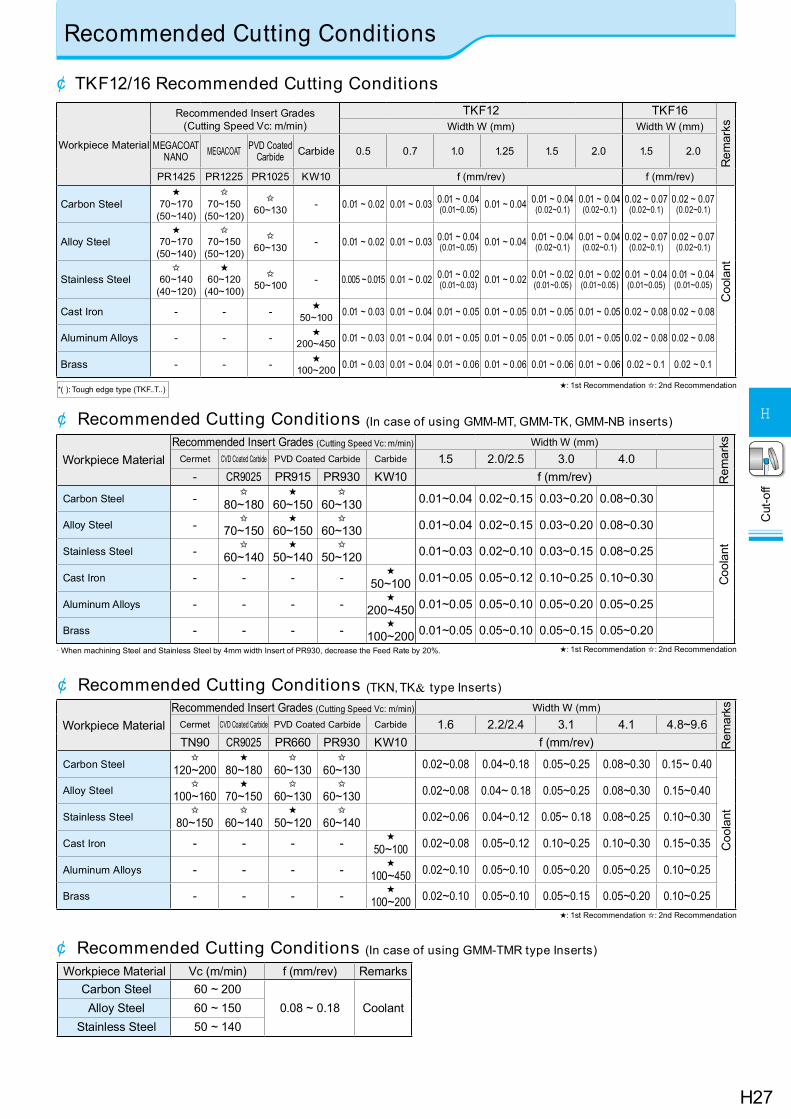
Recommended Cutting Conditions
¢ Recommended Cutting Conditions (TKN, TK& type Inserts)
★: 1st Recommendation ✩: 2nd Recommendation
Workpiece MaterialRecommended Insert Grades (Cutting Speed Vc: m/min) Width W (mm)
Rem
arks
Cermet CVD Coated Carbide PVD Coated Carbide Carbide 1.6 2.2/2.4 3.1 4.1 4.8~9.6TN90 CR9025 PR660 PR930 KW10 f (mm/rev)
Carbon Steel✩
120~200★
80~180✩
60~130✩
60~130 0.02~0.08 0.04~0.18 0.05~0.25 0.08~0.30 0.15~ 0.40
Coo
lant
Alloy Steel✩
100~160★
70~150✩
60~130✩
60~130 0.02~0.08 0.04~ 0.18 0.05~0.25 0.08~0.30 0.15~0.40
Stainless Steel✩
80~150✩
60~140★
50~120✩
60~140 0.02~0.06 0.04~0.12 0.05~ 0.18 0.08~0.25 0.10~0.30
Cast Iron - - - - ★50~100 0.02~0.08 0.05~0.12 0.10~0.25 0.10~0.30 0.15~0.35
Aluminum Alloys - - - - ★100~450 0.02~0.10 0.05~0.10 0.05~0.20 0.05~0.25 0.10~0.25
Brass - - - - ★100~200 0.02~0.10 0.05~0.10 0.05~0.15 0.05~0.20 0.10~0.25
¢ Recommended Cutting Conditions (In case of using GMM-MT, GMM-TK, GMM-NB inserts)
· When machining Steel and Stainless Steel by 4mm width Insert of PR930, decrease the Feed Rate by 20%.
Workpiece MaterialRecommended Insert Grades (Cutting Speed Vc: m/min) Width W (mm)
Rem
arks
Cermet CVD Coated Carbide PVD Coated Carbide Carbide 1.5 2.0/2.5 3.0 4.0- CR9025 PR915 PR930 KW10 f (mm/rev)
Carbon Steel - ✩80~180
★60~150
✩60~130 0.01~0.04 0.02~0.15 0.03~0.20 0.08~0.30
Coo
lant
Alloy Steel - ✩70~150
★60~150
✩60~130 0.01~0.04 0.02~0.15 0.03~0.20 0.08~0.30
Stainless Steel - ✩60~140
★50~140
✩50~120 0.01~0.03 0.02~0.10 0.03~0.15 0.08~0.25
Cast Iron - - - - ★50~100 0.01~0.05 0.05~0.12 0.10~0.25 0.10~0.30
Aluminum Alloys - - - - ★200~450 0.01~0.05 0.05~0.10 0.05~0.20 0.05~0.25
Brass - - - - ★100~200 0.01~0.05 0.05~0.10 0.05~0.15 0.05~0.20
★: 1st Recommendation ✩: 2nd Recommendation
Workpiece Material Vc (m/min) f (mm/rev) RemarksCarbon Steel 60 ~ 200
0.08 ~ 0.18 CoolantAlloy Steel 60 ~ 150Stainless Steel 50 ~ 140
¢ Recommended Cutting Conditions (In case of using GMM-TMR type Inserts)
¢ TKF12/16 Recommended Cutting Conditions
Workpiece Material
Recommended Insert Grades (Cutting Speed Vc: m/min)
TKF12 TKF16
Rem
arks
Width W (mm) Width W (mm)
MEGACOAT NANO MEGACOAT PVD Coated
Carbide Carbide 0.5 0.7 1.0 1.25 1.5 2.0 1.5 2.0
PR1425 PR1225 PR1025 KW10 f (mm/rev) f (mm/rev)
Carbon Steel★
70~170 (50~140)
✩70~150
(50~120)
✩ 60~130 - 0.01 ~ 0.02 0.01 ~ 0.03 0.01 ~ 0.04
(0.01~0.05) 0.01 ~ 0.04 0.01 ~ 0.04 (0.02~0.1)
0.01 ~ 0.04 (0.02~0.1)
0.02 ~ 0.07 (0.02~0.1)
0.02 ~ 0.07 (0.02~0.1)
Coo
lant
Alloy Steel★
70~170 (50~140)
✩70~150
(50~120)
✩ 60~130 - 0.01 ~ 0.02 0.01 ~ 0.03 0.01 ~ 0.04
(0.01~0.05) 0.01 ~ 0.04 0.01 ~ 0.04 (0.02~0.1)
0.01 ~ 0.04 (0.02~0.1)
0.02 ~ 0.07 (0.02~0.1)
0.02 ~ 0.07 (0.02~0.1)
Stainless Steel✩
60~140 (40~120)
★60~120
(40~100)
✩ 50~100 - 0.005 ~ 0.015 0.01 ~ 0.02 0.01 ~ 0.02
(0.01~0.03) 0.01 ~ 0.02 0.01 ~ 0.02 (0.01~0.05)
0.01 ~ 0.02 (0.01~0.05)
0.01 ~ 0.04 (0.01~0.05)
0.01 ~ 0.04 (0.01~0.05)
Cast Iron - - - ★50~100 0.01 ~ 0.03 0.01 ~ 0.04 0.01 ~ 0.05 0.01 ~ 0.05 0.01 ~ 0.05 0.01 ~ 0.05 0.02 ~ 0.08 0.02 ~ 0.08
Aluminum Alloys - - - ★200~450 0.01 ~ 0.03 0.01 ~ 0.04 0.01 ~ 0.05 0.01 ~ 0.05 0.01 ~ 0.05 0.01 ~ 0.05 0.02 ~ 0.08 0.02 ~ 0.08
Brass - - - ★100~200 0.01 ~ 0.03 0.01 ~ 0.04 0.01 ~ 0.06 0.01 ~ 0.06 0.01 ~ 0.06 0.01 ~ 0.06 0.02 ~ 0.1 0.02 ~ 0.1
★: 1st Recommendation ✩: 2nd Recommendation*( ): Tough edge type (TKF..T..)
H28
Cut
-off
H
Alternative Toolholder Reference Table for Cut-off Toolholder
Conventional Toolholder Alternative Toolholder
Description
Ove
rall l
engt
h (m
m) Spare Parts
Description
Ove
rall l
engt
h (m
m)
Remarks
Ref
. Pag
eClamp Screw Wrench
KTKF& 1010K-12 125
SB-4590TRWN LTW-10S
KTKF& 1010JX-12 120
H8
KTKF& 1212M-12 150 KTKF& 1212JX-12 120KTKF& 1616M-12 150 KTKF& 1616JX-12 120KTKF& 1010K-16 125 KTKF& 1010JX-16 120KTKF& 1212M-16 150 KTKF& 1212JX-16 120KTKF& 1616M-16 150 KTKF& 1616JX-16 120KGM& 0810K-1.5-125 125
SE-40120TR LTW-15S- - No replacement
H20
KGM& 1010K-1.5-125 125 KGM& 1010JX-1.5 120KGM& 1212M-1.5-150 150 KGM& 1212JX-1.5 120KGM& 0810K-2-125 125
SE-40120TR LTW-15S- - No replacement
KGM& 1010K-2-125 125 KGM& 1010JX-2 120KGM& 1212M-2-150 150 KGM& 1212JX-2 120KGM& 1616M-2-150 150 SE-50125TR LTW-20 KGM& 1616JX-2 120KGM& 1010K-2.5-125 125
SE-40120TR LTW-15SKGM& 1010JX-2.5 120
KGM& 1212M-2.5-150 150 KGM& 1212JX-2.5 120KGM& 1616M-2.5-150 150 SE-50125TR LTW-20 KGM& 1616JX-2.5 120KGM& 1616M-3-150 150 SE-50125TR LTW-20 KGM& 1616JX-3 120
Note) The corresponding alternative toolholder may be different from the conventional toolholder in insert clamping system or insert size.Make sure of their speci cations by referring to the catalog or other documents.
¢ Alternative Toolholder Reference Table for Cut-off Toolholder (KTKF / KGM)
Conventional Toolholder Alternative Toolholder
Description
Cut
-Off
Dia
.
Spare Parts
Description
Cut
-Off
Dia
.
Remarks
Ref
. Pag
eReleasing Wrench Clamp Bolt Wrench
KTKH& 0808K-1.6-125B f 10
- SE-40120TR FT-15
- - No replacement
H20
KTKH& 1010K-1.6-125B f 20 KGM& 1010JX-1.5 f 20KTKH& 1212M-1.6-150B f 25 KGM& 1212JX-1.5 f 25KTKH& 1414M-1.6-150B f 26 - - No replacementKTKH& 1010K-2-125B f 20
- SE-40120TR FT-15KGM& 1010JX-2 f 20
KTKH& 1212M-2-150B f 25 KGM& 1212JX-2 f 25KTKH& 1616M-2-150B f 32
- SE-50125TR LTW-20KGM& 1616JX-2 f 32
KTKH& 1616M-3-150B f 32 KGM& 1616JX-3 f 32
KTKHR 1010K-2-125S f 30
LTK-5 - -
KGMR 1010JX-2 f 20Processing diameter is
small.
KTKH& 1212M-2-150S f 30 KGM& 1212JX-2 f 25Processing diameter is
small.
KTKH& 1616M-2-150S f 36 KGM& 1616JX-2 f 32Processing diameter is
small.
KTKH& 1616M-3-150S f 45 KGM& 1616JX-3 f 32Processing diameter is
small.Note) The corresponding alternative toolholder may be different from the conventional toolholder in processing diameter or insert size.
Make sure their speci cations referring to the catalog or other documents.
¢ Alternative Toolholder Reference Table for Cut-off Toolholder (KTKH-B / KTKH-S)
FT
LTW


![Fisher zeros and correlation decay in the Ising model · 2020-02-07 · Pr[edge e is cut jedge f is cut] ˇPr[edge e is cut] The study of algorithms based on correlation decay (notably,Weitz’s](https://img.pdfslide.us/doc/110x75/5e71b4dda9e8b906fc02af62/fisher-zeros-and-correlation-decay-in-the-ising-model-2020-02-07-predge-e-is.jpg)