Embed Size (px)
Citation preview

NEW NEW
PF Chipbreaker withCorner R 0.006" is Now Available
New Sub SpindleToolholder Available
Stable Machining and Long Tool Life for Lower Production Costs
KGD for Small PartsSmall Diameter Cut-off
Edge Widths Available from 0.051" (1.3mm)
Excellent Chip Control
Long Tool Life with MEGACOAT NANO PR1535
2
Edge Widths Available from 0.051" (1.3mm)Excellent Chip Control and Stable Machining with Long Tool Life
KGD Cut-off for Small Parts
Excellent Chip Control with New Molded Chipbreaker2
Strong Insert Clamping Force3
Chipbreaker Lineup and Application1
Radial-shaped Surface on Toolholder
PF ChipbreakerDepression at center of chipbreaker curls chips at low feed range(f = 0.0004 ~ 0.0020 ipr).Small corner R (rε) = 0.0012", 0.0059"effectively reduces the boss remaining on the workpiece surface.
PQ ChipbreakerChipbreaker finely breaks chips with double the projection at medium feed range(f = 0.0016 ~ 0.0039 ipr).Corner R (rε) = 0.0039" combines both sharpness and fracture resistance.
Insert clamping force is improved by firmly fastening the front side (insert side) of the toolholder.
Insert clamping force and installation are improved by increasing contact area between the insert and toolholder.
Radial-shaped surface on the toolholder increases the contact area between the insert and toolholder.
Back Side
Toolholder clamps insert equally and firmly.
Front Side (Insert Side)
Toolholder
Insert
New Slit Design
Feed RateLowLow
High
High
PG for Sharp Cutting
Edge Width 0.079"~
PF for Low Feed Rates
Edge Width 0.051"~
PQ for Medium Feed Rates
Edge Width 0.079"~
PM for Medium-High Feed Rates
Edge Width 0.079"~
Cutt
ing
Forc
e
Depth of Cut (D.O.C.) 0.039" 0.059" 0.079" 0.118"
Feed Rate (f ) 0.010 ipr 0.012 ipr 0.010 ipr 0.012 ipr 0.010 ipr 0.012 ipr 0.010 ipr 0.012 ipr
KGD
Competitor ACompetitor B
Clamping Force Comparison (Traversing) Cutting Conditions: Vc = 260 sfm, f = ~ 0.012 ipr,D.O.C. = 0.039" ~ 0.118", wet (Oil Base) Workpiece: W1-9 (Ø0.394")
Stable Machining
(In-house Evaluation)

3
Case Studies
MEGACOAT Base Layer Structure
PR1535 is a good solution for unstable conditions such as early fracturing and variable tool life during steel machining.
Coating Property
0 50 100 150 200 250 300 350
0.014
0.012
0.010
0.008
0.006
0.004
0.002
0
Poor Chip Control
Poor Chip Control
Still Machinable
Number of Passes
Cutting Conditions: n = 1,273 rpm (Vc =260 sfm), f = 0.001 ipr, wet (oil base)Workpiece: 304 (Ø0.787")
Max
. Wea
r (in
)
Wear Resistance Evaluation (In-house Evaluation)
2X
Tool Life
Oxidation Resistance
40
35
30
25
20
15
10400 600 800 1,000 1,200 1,400
Low High
MEGACOATTiCN
TiNTiAIN
MEGACOAT NANO
Oxidation Temperature (°C)
Har
dnes
s (G
Pa)
MEGACOAT NANO PR1535Toughening with a New Cobalt Mixing Ratio* Comparison with Kyocera’s Conventional Grade
Improved Stability by Optimization and Homogenization of the Particle Matrix
Long Tool Life and Stable Machining with MEGACOAT NANO
The combination of a tough substrate and special nano layer coating enables long tool life and stable machining of stainless steel.
Conventional Material PR1535
Long Cracks Short Cracks
Cracking Comparison by Diamond Indenter (In-house Evaluation)23%
Fracture Toughness*
PR1535
Conventional J
Competitor K
0 200 400 600 800 1,000Number of Impacts
Cutting Conditions: Vc = 260 sfm, f = 0.005 ipr, wet (water soluble)Workpiece: 304 (Ø1.969, width: 0.394" 4 slots)
Fracture Resistance Comparison (In-house Evaluation)
No Fracturing
Ø1.
181”
Ø0.
315”
200 pcs/edge
400 pcs/edge
Machine Part 304Vc = 430 sfmf = 0.0016 iprWetGDM3020R-025PM-6D PR1535
PR1535
Competitor E
Compared to Competitor E, PR1535 showed good edge condition and doubled the tool life even at higher feed rates. (f = 0.0012 ipr 0.0016 ipr)
(User Evaluation)
2X
Tool LifeNumber of Workpieces
Ø0.
630”
800 pcs/edge
1,000 pcs/edge
Joint 304LVc = 260 sfmf = 0.020 iprWetGDM2020N-010PQ PR1535
PR1535
Competitor F
PR1535 extended the tool life by 25% compared to Competitor F. PQ chipbreaker showed smooth chip control and cutting edge condition was good without sudden fracturing.
(User Evaluation)
25%
Tool LifeNumber of Workpieces
Shock Resistance
1
2
3

4
Bottom Cutting Shape of PF/PM Chipbreaker
NEW NEW
· Corner R (rε) of PQ chipbreakers are small enough for small parts machining.· PF chipbreaker has a large corner R (rε).
For Recommended Cutting Conditions, see back cover.
Note: When grooving, PF/PM chipbreaker (for cut-off ) cannot create a flat bottom (see right figure).
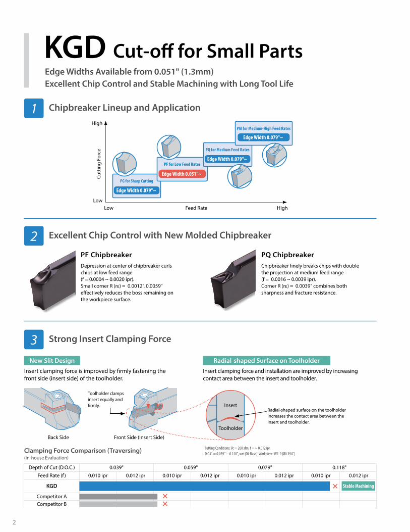
GDM / GDG Inserts
Usage Classification P Carbon Steel / Alloy Steel � �
� : Continuous to Light Interruption / 1st Choice� : Continuous to Light Interruption / 2nd Choice� : Continuous / 1st Choice� : Continuous / 2nd Choice
M Stainless Steel � �
N Non-ferrous Metals �
InsertRight-handed Insert Shown
Part Number
Dimensions (in) AngleMEGA COAT NANO
MEGACOAT DLC Carbide
Edge Width (W) Corner R(rε) M L H θ
PR15
35
PR12
25
PR12
15
PDL0
25
GW15
inch mm Tolerance
Cut-o
ff
Low Feed Rate2-Edge
L
2.5°
2.5°±0
.0016
”W
M rε
rε
H
GDM 1316N-003PF 0.051 1.3 ±0.0016 0.0012 0.039 0.630 0.146 - ß ß ß
1316N-015PF 0.051 1.3 ±0.0016 0.0059 0.039 0.630 0.146 - ß ß ß
1516N-003PF 0.059 1.5 ±0.0016 0.0012 0.047 0.630 0.146 - Þ Þ ß
1516N-015PF 0.059 1.5 ±0.0016 0.0059 0.047 0.630 0.146 - Þ Þ ß
2020N-003PF 0.079 2.0 ±0.0016 0.0012 0.067 0.787 0.169 - Þ Þ
2020N-015PF 0.079 2.0 ±0.0016 0.0059 0.067 0.787 0.169 - Þ Þ ß
2520N-003PF 0.098 2.5 ±0.0016 0.0012 0.083 0.787 0.169 - Þ ß
2520N-015PF 0.098 2.5 ±0.0016 0.0059 0.083 0.787 0.169 - Þ Þ ß
3020N-003PF 0.118 3.0 ±0.0016 0.0012 0.091 0.787 0.169 - Þ Þ
3020N-015PF 0.118 3.0 ±0.0016 0.0059 0.091 0.787 0.169 - Þ Þ ß
15° Lead AngleLow Feed Rate 2-Edge
L
M
2.5°
2.5°
±0.00
16”
W rε
θ°
H
GDM 1316§-003PF-15D 0.051 1.3 ±0.0016 0.0012 0.039 0.630 0.146 15° ß ß ß
1516§-003PF-15D 0.059 1.5 ±0.0016 0.0012 0.047 0.630 0.146 15° Þ Å ß
1516§-015PF-15D 0.059 1.5 ±0.0016 0.0059 0.047 0.630 0.146 15° Å Å Ç
2020§-003PF-15D 0.079 2.0 ±0.0016 0.0012 0.067 0.787 0.169 15° Þ Þ
2020§-015PF-15D 0.079 2.0 ±0.0016 0.0059 0.067 0.787 0.169 15° Å Å Ç
2520§-003PF-15D 0.098 2.5 ±0.0016 0.0012 0.083 0.787 0.169 15° Þ Å
2520§-015PF-15D 0.098 2.5 ±0.0016 0.0059 0.083 0.787 0.169 15° Å Å Ç
3020§-003PF-15D 0.118 3.0 ±0.0016 0.0012 0.091 0.787 0.169 15° Þ Þ
3020§-015PF-15D 0.118 3.0 ±0.0016 0.0059 0.091 0.787 0.169 15° Å Å Ç
Medium Feed Rate2-Edge
L
3°3°±0
.0012
”W
M rε
rε
H
GDM 2020N-010PQ 0.079 2.0 ±0.0012 0.0039 0.067 0.787 0.169 - Þ Þ
2520N-010PQ 0.098 2.5 ±0.0012 0.0039 0.083 0.787 0.169 - Þ Þ
3020N-010PQ 0.118 3.0 ±0.0012 0.0039 0.091 0.787 0.169 - Þ Þ
15° Lead AngleMedium Feed Rate 2-Edge
L
3°3°±0
.0012
”W rε
θ°
M
H
GDM 2020§-010PQ-15D 0.079 2.0 ±0.0012 0.0039 0.067 0.787 0.169 15° Å Å
2520§-010PQ-15D 0.098 2.5 ±0.0012 0.0039 0.083 0.787 0.169 15° Å Ç
3020§-010PQ-15D 0.118 3.0 ±0.0012 0.0039 0.091 0.787 0.169 15° Å Å
Low Cutting Force 2-Edge
L
3° M
3°
rε
rε
H
W±0
.0008
” GDG 2020N-005PG 0.079 2.0 ±0.0008 0.0020 0.067 0.787 0.169 - ß ß ß ß
2520N-005PG 0.098 2.5 ±0.0008 0.0020 0.083 0.787 0.169 - ß ß ß ß
3020N-005PG 0.118 3.0 ±0.0008 0.0020 0.091 0.787 0.169 - ß ß ß ß
15° Lead AngleLow Cutting Force 2-Edge
L
3°3°W
±0.00
08” θ°
H
rε
M
GDG 2020§-005PG-15D 0.079 2.0 ±0.0008 0.0020 0.067 0.787 0.169 15° Ç Ç Ç Å
2520§-005PG-15D 0.098 2.5 ±0.0008 0.0020 0.083 0.787 0.169 15° Ç Ç Å Å
3020§-005PG-15D 0.118 3.0 ±0.0008 0.0020 0.091 0.787 0.169 15° Ç Ç Ç Å
Þ : U.S. Stock Å : U.S. Stock (R-hand Only)ß : World Express (Shipping: 7-10 Business Days) Ç : World Express (R-hand Only)
Inserts Sold in 10 Piece Boxes
5
No. of Edges
No Indication: 2-Edge S: 1-Edge
Insert length
16: 16mm20: 20mm
Corner-R (rε)
003: 0.03mm005: 0.05mm010: 0.10mm015: 0.15mm
020: 0.20mm025: 0.25mm030: 0.30mm
Accuracy
G: Class GM: Class M
Width
13: 1.3mm15: 1.5mm20: 2.0mm
25: 2.5mm30: 3.0mm40: 4.0mm
Hand of Tool
R: Right-handL: Left-handN: Neutral
GD M 30 6DPM- -Series
Cut-off GD series
S 20 R 025
Chipbreaker Symbol
PF: Cut-off (Low Feed)PQ: Cut-off (Medium Feed)PG: Cut-off (Low Cutting Force)
PM: Cut-offGM: Grooving
Lead angle
No Indication: 0°6D: 6°
Insert Identification System
Applicable range
Low
Low
High
High 0.004Feed Rate (ipr)
PQ
PM/GM
PFPG
PF
PQ
Cutt
ing
Forc
e
NEW
Usage Classification P Carbon Steel / Alloy Steel � � � �
� : Continuous to Light Interruption / 1st Choice� : Continuous to Light Interruption / 2nd Choice� : Continuous / 1st Choice� : Continuous / 2nd Choice
M Stainless Steel � � �
N Non-ferrous Metals �
InsertRight-handed Insert Shown
Part Number
Dimensions (in) Angle CermetMEGA COAT NANO
MEGACOAT
Wrε M L H θ
TN90
PR15
35
PR12
25
PR12
15
inch mm Tolerance
Cut-o
ff
2-Edge
H
3°3°W
±0.0
012”
L
M rε
rε
GDM 2020N-020PM 0.079 2.0 ±0.0012 0.008 0.059 0.787 0.169 - Þ Þ Þ
2520N-020PM 0.098 2.5 ±0.0012 0.008 0.077 0.787 0.169 - Þ Þ Þ
3020N-025PM 0.118 3.0 ±0.0012 0.010 0.091 0.787 0.169 - Þ Þ Þ
4020N-030PM 0.158 4.0 ±0.0012 0.012 0.130 0.787 0.169 - Þ Þ Þ
6° Lead Angle 2-Edge
H
L
M
rε
3°3°W±0
.001
2” θ GDM 2020§-020PM-6D 0.079 2.0 ±0.0012 0.008 0.059 0.787 0.169 6° Å Å Å
2520§-020PM-6D 0.098 2.5 ±0.0012 0.008 0.077 0.787 0.169 6° Å Å Ç
3020§-025PM-6D 0.118 3.0 ±0.0012 0.010 0.091 0.787 0.169 6° Å Å Å
1-Edge
H
rεL
M
3°3°
W±0
.001
2” GDMS 2020N-020PM 0.079 2.0 ±0.0012 0.008 0.059 0.787 0.169 - ß Þ Þ
3020N-025PM 0.118 3.0 ±0.0012 0.010 0.091 0.787 0.169 - ß ß ß
4020N-030PM 0.158 4.0 ±0.0012 0.012 0.130 0.787 0.169 - ß ß ß
6° Lead Angle 1-Edge
H
L
M
rε
θ
3°3°
W±0
.001
2” GDMS 2020§-020PM-6D 0.079 2.0 ±0.0012 0.008 0.059 0.787 0.169 6° Ç Å Å
3020§-025PM-6D 0.118 3.0 ±0.0012 0.010 0.091 0.787 0.169 6° Ç Å Å
4020§-030PM-6D 0.158 4.0 ±0.0012 0.012 0.130 0.787 0.169 6° Ç Å Ç
Groo
ving a
nd Cu
t-off
General Purpose 2-Edge
2°2°
W
L
M rε
rε
H
GDM 2420N-020GM 0.094 2.4 ±0.0012 0.008 0.077 0.787 0.169 - ß Þ Þ Þ
3020N-020GM 0.118 3.0 ±0.0012 0.008 0.091 0.787 0.169 - ß Þ Þ Þ
3020N-040GM 0.118 3.0 ±0.0012 0.016 0.091 0.787 0.169 - ß Þ Þ Þ
4020N-020GM 0.157 4.0 ±0.0012 0.008 0.130 0.787 0.169 - ß Þ Þ Þ
4020N-040GM 0.157 4.0 ±0.0012 0.016 0.130 0.787 0.169 - ß Þ Þ Þ
4020N-080GM 0.157 4.0 ±0.0012 0.032 0.130 0.787 0.169 - ß Þ Þ Þ
General Purpose 1-Edge
H2°
2°W
L
M
rε
GDMS 2220N-020GM 0.087 2.2 ±0.0012 0.008 0.069 0.787 0.169 - ß ß Þ ß
3020N-040GM 0.118 3.0 ±0.0012 0.016 0.091 0.787 0.169 - ß ß Þ ß
4020N-040GM 0.157 4.0 ±0.0012 0.016 0.130 0.787 0.169 - ß ß ß ß
GDM / GDMS Inserts
Þ : U.S. Stock Å : U.S. Stock (R-hand Only)ß : World Express (Shipping: 7-10 Business Days) Ç : World Express (R-hand Only)
Inserts Sold in 10 Piece Boxes

6
KGD (Small Diameter Cut-Off) Insert Width : 0.059"~0.157" (1.3mm~4.0mm)
Right-hand Insert Shown
Insert Seat Angle
ØDmax
H3
H1
H3
H4
H2
H1
B
h
WF
A
L2
L1
θθ
Insert Seat Angle
Toolholder Overhang Length
JX: 120mm
Applicable Inserts
GDM/GDMSEdge Width 1.3mm
Others
D38: ØDmax 38mm
Others
B: for Sub Spindle Tooling
K G DKGDS
Toolholder Hand
R: Right-handL: Left-hand
Shank Size
16 × 16mm
Applicable Inserts
GDM/GDMSEdge Width 3 ~ 4mm
Toolholder Identification System
Note) 0.157" (1.4mm) width insert can be installed in KGD§212JX-3, it is not recommended due to the toolholder’s rigidity.When machining large cutting dia. (over 1.417" or 36mm) with KGD§....-3D38 or KGD§...-3D42, use 1-edge inserts.Maximum workpiece diameter for 2-edge inserts is Ø1.417" (36mm).
Part Number
Stock
Unit
Cutting Dia. Dimensions Edge Width
WSpare Parts
Screw Wrench
R L ØDmax H1 = h H2 H3 H4 B L1 L2 F A θ MIN. MAX.
KGD§ 6-1.5JX Þ Þ
inch
0.787 0.375 0.098 0.177 0.315 0.375 4.75 0.709 0.351 0.047 1° - 0.059 SB-40120TR LTW-15S8-1.5JX Þ Þ 0.944 0.500 0.051 0.177 0.394 0.500 4.75 0.768 0.476 0.047 1° - 0.059 SB-40120TR LTW-15S
KGD§ 6-2JX Þ Þ 0.787 0.375 0.098 0.177 0.315 0.375 4.75 0.709 0.342 0.067 1° 0.078 0.118 SB-40120TR LTW-15S8-2JX Þ Þ 0.944 0.500 0.051 0.177 0.394 0.500 4.75 0.768 0.467 0.067 1° 0.078 0.118 SB-40120TR LTW-15S10-2JX Þ Þ 1.259 0.625 - 0.177 0.394 0.625 4.75 0.965 0.592 0.067 1° 0.078 0.118 SB-40120TR LTW-15S
KGD§ 6-2.4JX Þ Þ 0.787 0.375 0.098 0.177 0.315 0.375 4.75 0.709 0.336 0.079 1° 0.094 0.118 SB-40120TR LTW-15S8-2.4JX Þ Þ 0.944 0.500 0.051 0.177 0.394 0.500 4.75 0.768 0.461 0.079 1° 0.094 0.118 SB-40120TR LTW-15S10-2.4JX Þ Þ 1.259 0.625 - 0.177 0.394 0.625 4.75 0.965 0.586 0.079 1° 0.094 0.118 SB-40120TR LTW-15S
KGD§ 8-3JX Þ Þ 0.944 0.500 0.051 0.177 0.394 0.500 4.75 0.768 0.453 0.094 1° 0.118 0.118 SB-40120TR LTW-15S10-3JX Þ Þ 1.259 0.625 - 0.177 0.394 0.625 4.75 0.965 0.578 0.094 1° 0.118 0.157 SB-40120TR LTW-15S
KGD§ 10-3D38JX Þ Þ 1.496 0.625 - 0.236 0.394 0.625 4.75 1.142 0.578 0.094 1° 0.118 0.157 SE-50125TR LTW-2012-3D42JX Þ Þ 1.653 0.750 - 0.236 0.551 0.750 4.75 1.220 0.703 0.094 1° 0.118 0.157 SE-50125TR LTW-2043-3D42JX Þ Þ 1.653 0.750 - 0.236 0.551 0.500 4.75 1.220 0.453 0.094 1° 0.118 0.157 SE-50125TR LTW-20
KGD§ 1010JX-1.3 ß ß
mm
20 10 2 4.5 8 10 120 18.0 9.5 1.0 5° 1.3 1.3 SB-40120TR LTW-15S1212JX-1.3 ß ß 24 12 2 4.5 10 12 120 19.5 11.5 1.0 5° 1.3 1.3 SB-40120TR LTW-15S
KGD§ 1010JX-1.5 ß ß 20 10 2 4.5 8 10 120 18.0 9.4 1.2 5° 1.5 1.5 SB-40120TR LTW-15S1212JX-1.5 ß ß 24 12 2 4.5 10 12 120 19.5 11.4 1.2 5° 1.5 1.5 SB-40120TR LTW-15S
KGD§ 1212F-1.3 ß ß 24 12 2 4.5 10 12 85 19.5 11.5 1.0 5° 1.3 1.3 SB-40120TR LTW-15S1212F-1.5 ß ß 24 12 2 4.5 10 12 85 19.5 11.4 1.2 5° 1.5 1.5 SB-40120TR LTW-15S
KGD§ 1010JX-2 ß ß 20 10 2 4.5 8 10 120 18.0 9.15 1.7 1° 2.0 3.0 SB-40120TR LTW-15S1212JX-2 ß ß 24 12 2 4.5 10 12 120 19.5 11.15 1.7 1° 2.0 3.0 SB-40120TR LTW-15S1616JX-2 ß Þ 32 16 - 4.5 10 16 120 24.5 15.15 1.7 1° 2.0 3.0 SB-40120TR LTW-15S
KGD§ 1010JX-2.4 ß ß 20 10 2 4.5 8 10 120 18.0 9.0 2.0 1° 2.4 3.0 SB-40120TR LTW-15S1212JX-2.4 ß ß 24 12 2 4.5 10 12 120 19.5 11.0 2.0 1° 2.4 3.0 SB-40120TR LTW-15S1616JX-2.4 ß ß 32 16 - 4.5 10 16 120 24.5 15.0 2.0 1° 2.4 3.0 SB-40120TR LTW-15S
KGD§ 1212JX-3 ß ß 24 12 2 4.5 10 12 120 19.5 10.8 2.4 1° 3.0 3.0 SB-40120TR LTW-15S1616JX-3 Þ ß 32 16 - 4.5 10 16 120 24.5 14.8 2.4 1° 3.0 4.0 SB-40120TR LTW-15S
KGD§ 1212F-2 ß ß 24 12 2 4.5 10 12 85 19.5 11.15 1.7 1° 2.0 3.0 SB-40120TR LTW-15S1212F-2.4 ß ß 24 12 2 4.5 10 12 85 19.5 11.0 2.0 1° 2.4 3.0 SB-40120TR LTW-15S
KGD§ 1616JX-3D38 ß ß 38 16 - 6.0 10 16 120 29.0 14.8 2.4 1° 3.0 4.0 SE-50125TR LTW-202012JX-3D42 ß ß 42 20 - 6.0 14 12 120 31.0 10.8 2.4 1° 3.0 4.0 SE-50125TR LTW-202020JX-3D42 ß ß 42 20 - 6.0 14 20 120 31.0 18.8 2.4 1° 3.0 4.0 SE-50125TR LTW-20
R JX -
Þ : U.S. Stock ß : World Express (Shipping: 7-10 Business Days)
1616 31.3
D38B
7
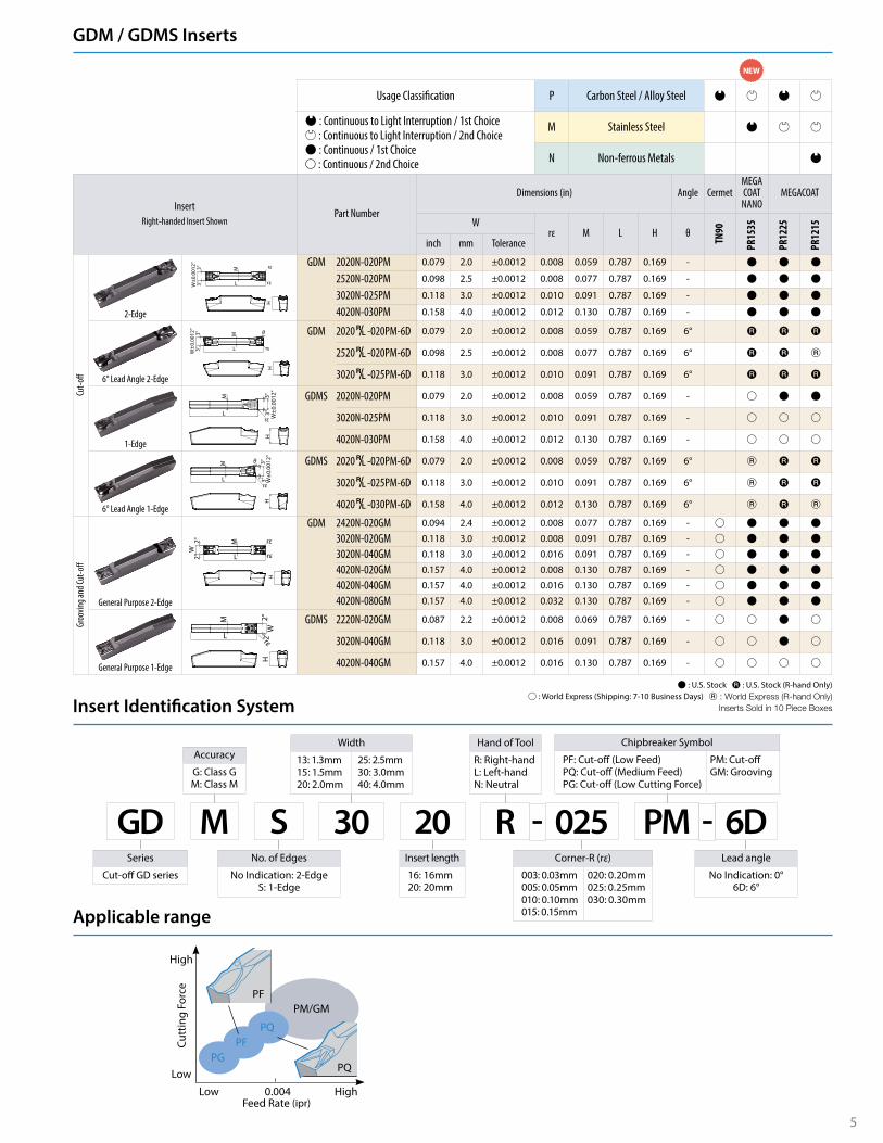
KGD Standard TypeBoth Right-hand and Left-hand types are applicable to gang tool post. Left-hand type is recommended for cut-off operations when using a sub-spindle.
KGDS Sub Spindle TypeThe KGDS can be used to reduce overhang distance from the main spindle when cutting off small diameter workpieces.
Right-hand
ØDmax
B
h
F
L3
HH3
L2W
A
H2
L1
θ
A
ØDmax
BH
L1
hH3
L3
L2
FW
H2
θ
Left-hand
KGDS (for Cut-Off Operation Near Sub Spindle Side)
KGD / KGDS Selection Reference
Part Number
Stock
Unit
Cutting Dia. Dimensions Edge Width
WSpare Parts
Screw Wrench
R L ØDmax H1 = h H2 H3 H4 B L1 L2 F A θ MIN. MAX.
KGDS§ 1616JX-1.3B ß ß
mm
24 16 4.5 10 16 120 19.5 27 9.50 1.0 5.0 1.3 1.3 SB-40120TR LTW-15S
KGDS§ 1616JX-1.5B ß ß 24 16 4.5 10 16 120 19.5 27 9.40 1.2 5.0 1.5 1.5 SB-40120TR LTW-15S
KGDS§ 1616JX-2B ß ß 24 16 4.5 10 16 120 19.5 27 9.15 1.7 1.0 2.0 3.0 SB-40120TR LTW-15S
KGDR (Right-hand) KGDL (Left-hand)
Recommendations (Right-hand)· Use insert with lead angle to remove boss· Not using sub-spindle· Cut-off close to main spindle side
Recommendations (Left-hand)· Insert without lead angle· Sub-spindle use· Cut-off close to sub-spindle side
Mai
n S
pin
dle
Mai
n S
pin
dle
Sub
Sp
ind
le
KGDSR (Right-hand) KGDSL (Left-hand)
Recommendations (Right-hand)· Long workpiece· Good rigidity· Cut-off near main spindle side
Recommendations (Left-hand)· Short workpiece· Poor rigidity· Cut-off near sub-spindle side
Mai
n S
pin
dle
Sub
Sp
ind
le
Mai
n S
pin
dle
Sub
Sp
ind
le
ß : World Express (Shipping: 7-10 Business Days)
KYOCERA Precision Tools, Inc.102 Industrial Park RoadHendersonville, NC 28792Customer Service | 800.823.7284 - Option 1Technical Support | 800.823.7284 - Option 2
Official Website | www.kyoceraprecisiontools.comDistributor Website | mykpti.kyocera.comEmail | [email protected] ©KYOCERA Precision Tools, Inc.
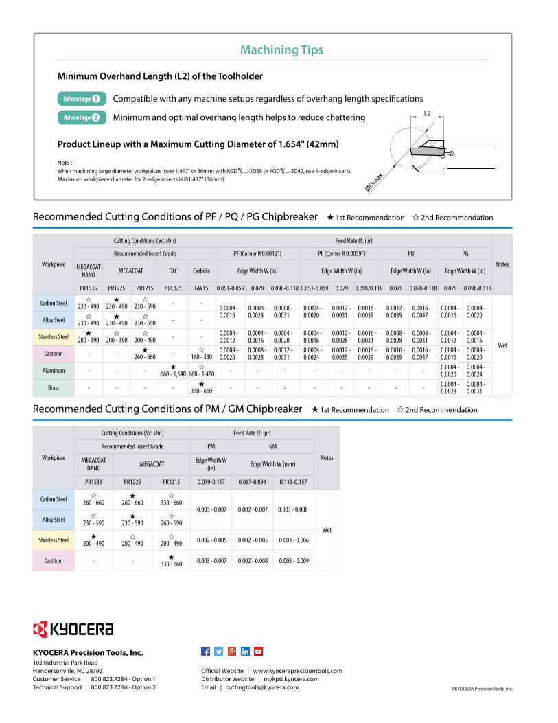
Note : When machining large diameter workpeices (over 1.417" or 36mm) with KGD§....-3D38 or KGD§...-3D42, use 1-edge insertsMaximum workpiece diameter for 2-edge inserts is Ø1.417" (36mm)
Compatible with any machine setups regardless of overhang length specifications
Minimum and optimal overhang length helps to reduce chattering
ØDmax
L2
Machining Tips
Minimum Overhand Length (L2) of the Toolholder
Product Lineup with a Maximum Cutting Diameter of 1.654" (42mm)
Advantage
Advantage
Workpiece
Cutting Conditions (Vc: sfm) Feed Rate (f: ipr)
Notes
Recommended Insert Grade PF (Corner R 0.0012") PF (Corner R 0.0059") PQ PG
MEGACOAT NANO MEGACOAT DLC Carbide Edge Width W (in) Edge Width W (in) Edge Width W (in) Edge Width W (in)
PR1535 PR1225 PR1215 PDL025 GW15 0.051-0.059 0.079 0.098-0.118 0.051-0.059 0.079 0.098/0.118 0.079 0.098-0.118 0.079 0.098/0.118
Carbon Steel 230 - 490 230 - 490 230 - 590 - -0.0004 - 0.0016
0.0008 - 0.0024
0.0008 - 0.0031
0.0004 - 0.0020
0.0012 - 0.0031
0.0016 - 0.0039
0.0012 - 0.0039
0.0016 - 0.0047
0.0004 - 0.0016
0.0004 - 0.0020
Wet
Alloy Steel 230 - 490 230 - 490 230 - 590 - -
Stainless Steel 200 - 390 200 - 390 200 - 490 - - 0.0004 - 0.0012
0.0004 - 0.0016
0.0004 - 0.0020
0.0004 - 0.0016
0.0012 - 0.0028
0.0016 - 0.0031
0.0008 - 0.0028
0.0008 - 0.0031
0.0004 - 0.0012
0.0004 - 0.0016
Cast Iron - - 260 - 660 - 160 - 3300.0004 - 0.0020
0.0008 - 0.0028
0.0012 - 0.0031
0.0004 - 0.0024
0.0012 - 0.0035
0.0016 - 0.0039
0.0016 - 0.0039
0.0016 - 0.0047
0.0004 - 0.0016
0.0004 - 0.0020
Aluminum - - - 660 - 1,640 660 - 1,480 - - - - - - - - 0.0004 - 0.0020
0.0004 - 0.0024
Brass - - - - 330 - 660 - - - - - - - - 0.0004 - 0.0028
0.0004 - 0.0031
Recommended Cutting Conditions of PF / PQ / PG Chipbreaker 1st Recommendation 2nd Recommendation
Workpiece
Cutting Conditions (Vc: sfm) Feed Rate (f: ipr)
Notes
Recommended Insert Grade PM GM
MEGACOAT NANO MEGACOAT Edge Width W
(in) Edge Width W (mm)
PR1535 PR1225 PR1215 0.079-0.157 0.087-0.094 0.118-0.157
Carbon Steel 260 - 660 260 - 660 330 - 660 0.003 - 0.007 0.002 - 0.007 0.003 - 0.008
WetAlloy Steel 230 - 590 230 - 590 260 - 590
Stainless Steel 200 - 490 200 - 490 200 - 490 0.002 - 0.005 0.002 - 0.005 0.003 - 0.006
Cast Iron - - 330 - 660 0.003 - 0.007 0.002 - 0.008 0.003 - 0.009
Recommended Cutting Conditions of PM / GM Chipbreaker 1st Recommendation 2nd Recommendation