Embed Size (px)
Citation preview
Customer Metering and Services Guide
This document is an uncontrolled copy and may not be the most current copy. The most current copy is available at www.atcoelectric.com. This document is the property of ATCO Electric and may be updated at any time.
Customer Metering and Services Guide
Revised Dec-09 - 1 -
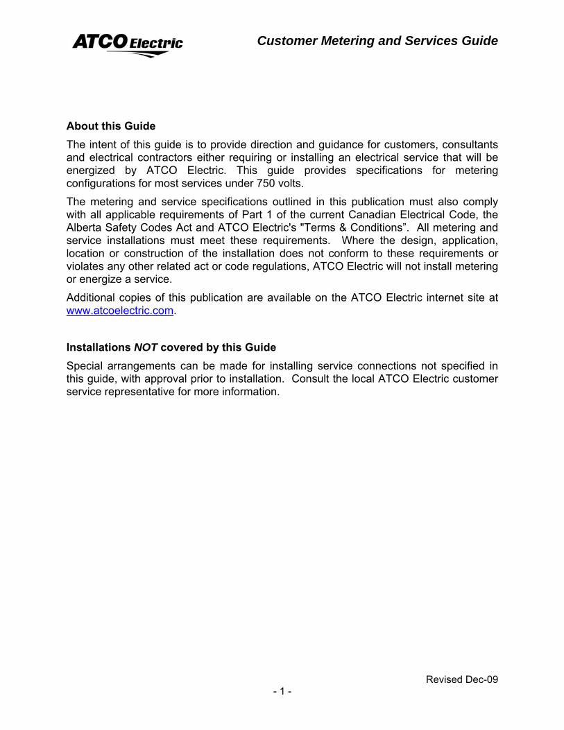
About this Guide The intent of this guide is to provide direction and guidance for customers, consultants and electrical contractors either requiring or installing an electrical service that will be energized by ATCO Electric. This guide provides specifications for metering configurations for most services under 750 volts.
The metering and service specifications outlined in this publication must also comply with all applicable requirements of Part 1 of the current Canadian Electrical Code, the Alberta Safety Codes Act and ATCO Electric's "Terms & Conditions”. All metering and service installations must meet these requirements. Where the design, application, location or construction of the installation does not conform to these requirements or violates any other related act or code regulations, ATCO Electric will not install metering or energize a service.
Additional copies of this publication are available on the ATCO Electric internet site at www.atcoelectric.com.
Installations NOT covered by this Guide Special arrangements can be made for installing service connections not specified in this guide, with approval prior to installation. Consult the local ATCO Electric customer service representative for more information.

Customer Metering and Services Guide
Revised Dec-09 - 2 -
Customer Metering and Services Guide
Revised Dec-09 - 3 -
Table of Contents List of Drawings and Tables 5
Glossary 7
GENERAL INFORMATION 9 APPLICATION FOR SERVICE AND GENERAL REQUIREMENTS 13
Non-Standard Services 16
RESIDENTIAL SERVICES 17
Single Phase Residential Services − Self-Contained Metering 18
Single Phase Residential Services − Instrument Transformer Metering 29
Multiple Customer Metering 30
FARM SERVICES 35
Single Phase Farm Services − Self-Contained Metering 36
Single Phase Farm Services − Instrument Transformer Metering 41
Three Phase Farm Services − Self-Contained Metering 43
Three Phase Farm Services − Instrument Transformer Metering 44
COMMERCIAL SERVICES 47
Single Phase Commercial Services − Self-Contained Metering 48
Single Phase Commercial Services − Instrument Transformer Metering 50
Three Phase Commercial Services − Self-Contained Metering 53
Three Phase Commercial Services − Instrument Transformer Metering 54
INDUSTRIAL SERVICES 57
Single Phase Industrial Services − Self-Contained Metering 58
Single Phase Industrial Services − Instrument Transformer Metering 60
Three Phase Industrial Services − Self-Contained Metering 63
Three Phase Industrial Services − Instrument Transformer Metering 64
MICRO−GENERATION 71 TEMPORARY SERVICES & IDLE SERVICES 73 INSTRUMENT TRANSFORMERS 75 MANUFACTURED SWITCHGEAR FOR SERVICES & METERING 87
Customer Metering and Services Guide
Revised Dec-09 - 4 -
Appendix 89
Diagrams of Socket Connections 89
Diagram of Socket Connections − continued 90
Wiring Diagram for Grounding Resistors 91
Design Clearances on Underground Distribution 93
Sizing of Building Alcove for Locating a Padmounted Transformer 94
Typical Alignment on Front Street Monolithic Curb/Sidewalk 95
Typical Alignment on Front Street Boulevard / Rear Traffic Lane 96
Typical Alignment on Rear Lot Utility Lane / Rear Easement Access 97
Landscaping Adjacent to Underground Electrical Equipment 98
Landscaping Adjacent to Padmount Transformer and Pedestal 99
Landscaping Adjacent to Padmount Switch Cable and Street Light 100
Protective Guard Posts for Padmounted Transformer or Switching Cubicles
(Open Areas) 101
Protective Guard Posts for Padmounted Transformer Located in Alcoves 102
Customer Metering and Services Guide
Revised Dec-09 - 5 -
List of Drawings and Tables Standard Overhead Distribution Voltages 10
Standard Underground Distribution Voltages 10
Recommended Voltage Variation Limits 11
Underground Residential Pedestal, Service and Cable Stubbing Arrangement 22
Multiple Services in a Multiple Dwelling 23
Optional Townhouse Multi−Meter Detail 24
Multi-Port Connection Terminals for AMR 25
Acreage Customer Owned Secondary - Mounted on a Pole 28
Typical Arrangement for Multiple Customer Metering 32
Quadlogic “miniCloset” Metering Equipment 33
Farm Type Metering 38
Padmount Transformer and Underground Service on a Farm 39
Installation of Multi-Breaker Box for Farm Type Metering of 2 Services 40
ATCO Electric Standard for Self-contained Metering of 100 or 200 amp on
An Oilfield Service Pole 66
Pole Metering for Oilfield Loads Over 200 Amps 67
Customer Owned Metering in a Building, for Oilfield Loads Over 200 Amps 68
Secondary Overhead to Underground Riser on a Pole 69
Meter Requiring Instrument Transformers 76
Typical Connections for 3 Phase 4 Wire Wye Services 77
Meter and Test Switch Enclosures 78
Single Phase, 3W 120/240 Volt Instrument Metering 79
3 Phase, 4W 120/208Y Volt Instrument Metering 80
3 Phase, 4W 277/480Y or 347/600Y V Instrument Metering 81
Bolting Instrument Transformer 82
3 Phase, 4W 347/600Y V Instrument Metering – AMR Equipped 83
2 Wire Current Transformer 600V Class 84
Window Type Current Transformer 600V Class 85
Voltage Transformer 600V Class 86
Customer Metering and Services Guide
Revised Dec-09 - 6 -
Diagrams of Socket Connections 89
Diagrams of Socket Connections cont’d 90
Wiring Diagram for Grounding Resisters 91
Design Clearances on Underground Distribution 93
Sizing of Building Alcove for Locating a Padmounted Transformer 94
Typical Alignment on Front Street Monolithic Curb / Sidewalk 95
Typical Alignment on Front Street Boulevard 96
Typical Alignment on Rear Lot Utility Lane 97
Landscaping Adjacent to Underground Electrical Equipment 98
Landscaping Adjacent to Padmount Transformer and Pedestal 99
Landscaping Adjacent to Padmount Switch Cubicle or Street Light 100
Protective Guard Posts for Padmounted Transformer or Switching Cubicles
(Open Areas) 101 Protective Guard Posts for Padmounted Transformer Located in Alcoves 102
Customer Metering and Services Guide
Revised Dec-09 - 7 -
Glossary
AMR − Automatic Metering Reading
AMI – Advanced Metering Infrastructure refers to a system that measures, collects and analyses energy usage, from advanced devices such as electricity meters, gas meters and / or water meters, through various communication media on request or on a predefined schedule. This infrastructure includes hardware, software, communications; Customer associated systems and meter data management software.
CEC − Canadian Electrical Code, Part 1 and Amendments
CMT – Commercial Metering Transponder for AMR
CSA − Canadian Standards Association
CT – Current Transformer
AECUC − Alberta Electrical and Communications Utility Code
Demand − The average value of power over a specified interval of time. The most common quantities are kilowatt (kW) and kilovolt amperes (kVA) demand.
Energy − The integral of active power with respect to time. E.g. kilowatt-hours (kWh)
Ground – The conductor that only carries current under a fault condition, not to be used as Neutral.
Harmonics − Are distortions to the voltage and current waveforms from their normal sinusoidal shape.
IMT − Integrated Metering Transponder for AMR
Instrument Transformer Metering − Using a transformer in a metering circuit to step down the current and/or the voltage to a level that can be accommodated safely by the meter.
Interval Data Metering − Revenue meters that have mass memory data storage capability.
Measurement Canada − Oversees the sealing and verification of electric meters used for revenue consumption.
Meter Base – typically a socket style device for the connection to a self-contained meter.
Metering Services Provider – Owns and maintains the revenue meters on the distribution system.
Meter Socket and Test Switch Enclosure – meter socket with a pre-wired metering test switch for use with current and/or voltage transformers enclosed in a metal housing.
MIT – Meter Interface Transponder for AMR
Customer Metering and Services Guide
Revised Dec-09 - 8 -
Multiple Customer Metering – Multiple residential metering where the building does not use standard individual meters for each suite. The metering uses “mini” CT’s on each branch circuit.
Multiple Service − A service to a building such as an apartment building or shopping centre that has two or more units and a common service entrance in which each unit is served and metered separately.
Network – Two phase wires and the Neutral from a three phase four wire wye system that form a three wire service for residential type loads.
Neutral – The conductor from the transformer Star point that carries the imbalanced load current and provides a reference point for the metering potentials, the “grounded” conductor.
Non-Farm – A service where the Customer in not engaged in a farming application.
Non− REA – A service where the Customer does not belong to a Rural Electrification Association.
R.E.A.L − Rural Electrification Association Limited (REA)
Retailer − Markets electrical energy or electrical services to consumers.
Rural Service – A service in a rural area where the Customer does not farm or belong to a REA.
Self-Contained Meter − A meter designed to accommodate the full line current and Voltage of the circuit.
SCA − Alberta Safety Codes Act
Settlement System Code − Agreement between retailers, wire service providers, transmission service providers, the independent system operator meeting the requirements of the Alberta Electric Utilities Act.
VT – Voltage Transformer
The Company − ATCO Electric.
Wire Service Provider − Owns and operates the electric distribution system.
Customer Metering and Services Guide
Revised Dec-09 - 9 -
GENERAL INFORMATION Types of Metering The type of metering specified by the Company shall depend on the class of service, size of load to be served and the applicable rate, for e.g.: energy, kW or kVA demand. The Company shall install, maintain and own all meters, except for meters on R.E.A.L. member services, where they are owned by the R.E.A.L. Independent Power Producers may also own their own meter but it must conform to the Measurement System Standard for the province of Alberta.
All meters must be sealed, maintained and tested according to Measurement Canada standards.
Self-Contained Metering Used for metering loads up to and including 600 volts where the main breaker does not exceed 200 amps. (single phase to 480 and three phase to 600 volts)
Instrument Metering Used for metering loads where the main breaker is greater than 200 amperes and/or over 600 volts. On loads over 500 kW, interval data meters are required.
Optional Customer Pulse − Upon request a pulse output meter or devices such as transducers and pulse duplicating relays may be installed in the Customers metering circuit. The Customer will discuss data acquisition needs with the Company early in the project planning stages. The Company installs the optional pulse devices and the Customer will be billed for costs above the Company's standard installations.
Customer Choice Metering – Upon request, an interval data meter can be installed on a Customer installation that is <500 kW. The Customer will request the meter be installed and will be billed for the costs above the Company’s standard installation and for a monthly fee to collect the interval data.
Standard Three Phase Metering Configuration All new three phase services are to be four wire wye (Star) systems, metered three element with the Neutral (grounded conductor) forming part of the metering circuit. The Neutral conductor must be connected between the transformer or point of supply and the metering point of all three phase, four wire, wye systems. The Neutral must be grounded at the main service disconnect. The use of an isolated Neutral block is necessary when the metering point is on the load side of the main service disconnect.
Primary Metering Primary metering is available for multi−voltages or services normally over 1000 kVA.
Unmetered Services The Company does not allow unmetered services. All services must be metered with Measurement Canada approved revenue meters to comply with the Alberta Settlement System Code requirements.
Customer Metering and Services Guide
Revised Dec-09 - 10 -
Standard Supply Voltages The following tables show the Company's standard overhead and underground voltage, phase and load configurations. Not all standard voltages are available at all locations:
Table 1 Standard Overhead Distribution System
Service Voltage Phase / Wire Transformer Load Range
Full Load Range Line Amperes
120/240 Single Phase, 3 Wire 10 to 167 kVA
(may be larger for Special loads)
@120 83 to 1391
Amps
@240 41 to 696 Amps
120/208Y Three Phase, 4 Wire 30 to 300 kVA 83 to 833 Amps
277/480Y Three Phase, 4 Wire 15 to 3000 kVA 18 to 3610 Amps
347/600Y Three Phase, 4 Wire 150 to 3000 kVA 144 to 2887 Amps
Table 2 Standard Underground Distribution System
Service Voltage Phase / Wire Transformer Load Range
Full Load Range Line Amperes
120/240 Single Phase, 3 Wire 10 to 100 kVA @120
83 to 833 Amps
@120 41 to 416 Amps
120/208Y Three Phase, 4 Wire 75 to 500 kVA 208 to 1388 Amps
277/480Y Three Phase, 4 Wire 30 to 4000 kVA 36 to 4813 Amps
347/600Y Three Phase, 4 Wire Minimum 150 kVA 144 Amps and Up
Other Voltages Service may be provided at any required voltage, under mutually, satisfactory agreed terms. Requests for non-standard voltage supply must be approved by the Company.
Voltage Operating Conditions All services are alternating current 60 hertz. The normal system voltage and voltage limits at the service entrance are as specified in the Canadian Electrical Association Reference Standard for Canadian Practice "Preferred Voltage Levels for AC Systems 0 − 50,000 volts" and CSA Standard CAN 3−C235−83, Table 3.
Customer Metering and Services Guide
Revised Dec-09 - 11 -
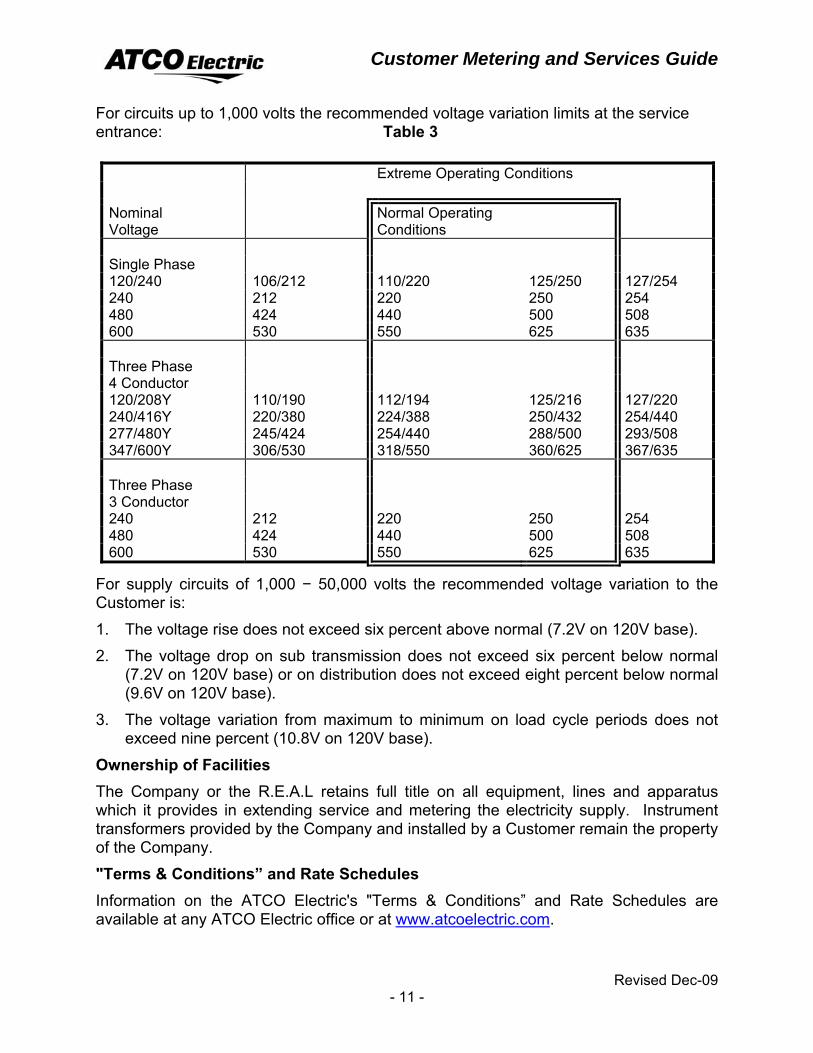
For circuits up to 1,000 volts the recommended voltage variation limits at the service entrance: Table 3
Extreme Operating Conditions Nominal Voltage
Normal Operating Conditions
Single Phase 120/240 106/212 110/220 125/250 127/254 240 212 220 250 254 480 424 440 500 508 600 530 550 625 635 Three Phase 4 Conductor 120/208Y 110/190 112/194 125/216 127/220 240/416Y 220/380 224/388 250/432 254/440 277/480Y 245/424 254/440 288/500 293/508 347/600Y 306/530 318/550 360/625 367/635 Three Phase 3 Conductor 240 212 220 250 254 480 424 440 500 508 600 530 550 625 635
For supply circuits of 1,000 − 50,000 volts the recommended voltage variation to the Customer is:
1. The voltage rise does not exceed six percent above normal (7.2V on 120V base).
2. The voltage drop on sub transmission does not exceed six percent below normal (7.2V on 120V base) or on distribution does not exceed eight percent below normal (9.6V on 120V base).
3. The voltage variation from maximum to minimum on load cycle periods does not exceed nine percent (10.8V on 120V base).
Ownership of Facilities The Company or the R.E.A.L retains full title on all equipment, lines and apparatus which it provides in extending service and metering the electricity supply. Instrument transformers provided by the Company and installed by a Customer remain the property of the Company.
"Terms & Conditions” and Rate Schedules Information on the ATCO Electric's "Terms & Conditions” and Rate Schedules are available at any ATCO Electric office or at www.atcoelectric.com.
Customer Metering and Services Guide
Revised Dec-09 - 12 -
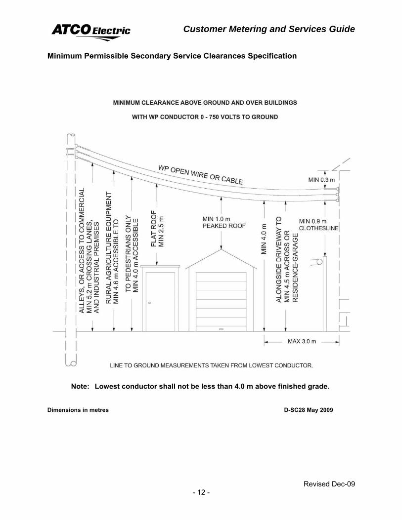
Minimum Permissible Secondary Service Clearances Specification
Note: Lowest conductor shall not be less than 4.0 m above finished grade. Dimensions in metres D-SC28 May 2009
Customer Metering and Services Guide
Revised Dec-09 - 13 -
APPLICATION FOR SERVICE AND GENERAL REQUIREMENTS The Customer should apply for service early in the planning stage of a project in order for the Company to meet the Customer's needs, determine the best service arrangement and to provide the time to obtain necessary equipment.
Contact the local Customer Service Representative or see application requirements on www.atcoelectric.com.
The Customer shall provide the Company with all the necessary information regarding the type of service, connected loads, timing, service voltage and a site plan. A service agreement may be required with the Company's "Terms & Conditions” and the rate schedule applicable to the service. A Customer contribution may be required.
Service Voltage and Location The service voltage is the voltage and phase(s) requested by the Customer. Each service will be at one of the standard voltages listed in this guide and will be metered appropriately. Requests for voltage supply must be approved by the Company. The service location on the Customer's premises is subject to approval of the Company.
Service Entrance Drawings To ensure the Customer does not experience any delays on a service entrance over 200 amperes, three sets of drawings of the service entrance, service location and service, and metering layout shall be submitted to a Company Customer service or marketing representative. The drawings shall be stamped final and initialed by the issuing consultant or electrical contractor. All installations shall comply with the applicable requirements of the Canadian Electrical Code and Alberta Safety Codes Act regulations.
Access The Company has the right, and will endeavor to make reasonable arrangements, to enter the Customer's property or premises to install, inspect, read, change, maintain and remove its facilities.
For Company facilities located within locked Customer premises the Customer shall provide a means of access.
In subdivisions, the developer shall provide easement at no cost to the Company where required for access, and for providing service extensions to each parcel of property.
Meter Locations All metering and service locations shall be approved by the Company prior to installation. Meters shall be located either on the line side where the voltage is less than 300V line to line or load side of the Customer's main breaker (disconnect) where the voltage is greater than 300V line to line as detailed in the Canadian Electrical Code. Company personnel must have reasonable access to the meter to perform meter changes, testing and meter reads.
Customer Metering and Services Guide
Revised Dec-09 - 14 -
The Company will not install meters in alleyways or areas where the meter is unprotected from moving equipment, in the path of water from eaves or rain spouts or where the meter may be subject to steam, corrosive hazardous vapors.
The Company will not install meters in areas that are difficult to access areas such as;
• Inside all biologically hazardous areas, poultry / pork or any other livestock facilities where the spread of disease or virus is possible. This includes directly under any vents or fans that move air to or from the building.
• No meters shall be mounted in a known H2S environment. The meter must be installed outside of this zone.
• open pits,
• near moving machinery,
• hatchways,
• closets or stairways
• where there are noticeable vibrations.
Splitter Box Location A splitter box must not be installed ahead of the meter or service disconnect. The instrument transformer enclosure can not be used as a splitter box.
Wiring Permit A copy of a signed electrical wiring permit shall be presented to the Company before the electrical service is connected on a new, altered or relocated service. Retailer The Customer must have a retailer before a service can be energized. A retailer or any other person acting as an agent of a Customer may apply for a service connection on behalf of the Customer. The Retailer or agent must provide the Company, in a form acceptable to the Company, verifiable authorization from the Customer to make the application.
Relocations Where a building extension encloses or interferes with existing metering, the Company will relocate the service at the Customer's expense. There is no charge if the overhead service conductors and the meter only are relocated.
The Company will, at the request of a Customer, relocate the facilities installed to service the Customer, provided the Customer pays all costs of such relocation. There will be no charge to relocate only the meter and overhead service conductors.
Customer Metering and Services Guide
Revised Dec-09 - 15 -
Modifications Customers shall obtain written approval from the Company before modifying an existing service which may affect the metering. The Customer may be charged for costs associated with any change required to the Company's facilities due to the service modification.
Customer Grounding Resistor Refer to page 91, Wiring Diagram for Grounding Resistors.
Load Changes A Customer shall advise the Company in writing of any changes to their load requirements so that the Company may determine if service changes are required to accommodate the increased load. The Customer shall provide sufficient time for the Company to obtain equipment and make the necessary changes. If a Customer has not obtained permission from the Company the Customer can be held responsible for any damage to the Company's property or equipment resulting from a major change in a load.
Harmonic Loading Additions The Customer shall notify the Company when harmonic loads such as VFD (variable frequency drive) motors are added to an existing utility transformer. If the calculated harmonic current is in excess of 5% of the utility transformer rated current as stated in IEEE C57.12.00 -− 1987, the transformer may have to be changed. The Customer shall be responsible for any incremental costs associated with the transformer change.
Harmonic Distortion All Customers with loads producing harmonic distortion shall comply with the "ATCO Electric Transmission and Distribution System Guide to Nonlinear Load Additions". This document follows The Institute of Electrical and Electronics Engineers 519−1992 "IEEE Recommended Practices and Requirements for Harmonic Control in Electric Power Systems" with some ATCO Electric modifications which take precedence over IEEE 519−1992. This guide outlines the procedures, information and technical requirements to be observed from the initial design stages to the energizing of the harmonic producing load installation. Contact your local Company representative for a copy of this document.
For detailed information on Harmonics and New Loads please refer to the ATCO Electric webpage www.atcoelectric.com. Go to Forms and Publications, “Distribution System Standard for the Installation of New Load”.
Three Phase Loads The Customer is responsible for single phase protection on three phase loads.
Electronic Loads The Customer is responsible for protecting all sensitive electronic loads against transients caused by such events as lightning or utility switching.
Customer Metering and Services Guide
Revised Dec-09 - 16 -
Non-Standard Services Service and metering requirements not covered in the guide are to be discussed with the local Company representative. The Customer shall submit three sets of drawings of the service entrance, service location and service and metering layout to a Company Customer service representative. The drawings shall be stamped final and initialed by the issuing consultant or electrical contractor. All installations shall comply with the applicable requirements of the CEC and SCA regulations. The Company will make every effort to meet the Customer's needs.
Power Factor A Customer shall design, install and operate the Customer's facilities in such a manner as to maintain a Power Factor of not less than 90%. The Company may require any Customer not satisfying this Power Factor requirement to furnish, install, and maintain, at no cost to the Company, such corrective equipment as the Company may deem necessary under the circumstances.
Customer Metering and Services Guide
Revised Dec-09 - 17 -
RESIDENTIAL SERVICES
Residential services are generally self-contained metering services to an urban or rural house or dwelling.
Note: REA and Farm residences are not covered by this section. See “Farm Services” for those applications.
General Requirements ♦ Metering shall be located on the line side of the Customer's main breaker.
♦ Metering shall be located on the outside wall of the house except for rural residential services which may utilize pole metering. The Company will advise the Customer if pole metering is to be used.
♦ Where recessed metering is installed in a wall, a clear space of not less than 0.2 metres on either side of the centre line of the meter base and 1.0 metre in front of the meter is required, to provide the Company access to the meters.
♦ The centre line of the meter socket shall be 1.5 to 1.8 metres above the finished grade or permanent platform.
♦ The meter socket must not have a self shorting device.
Customer Metering and Services Guide
Revised Dec-09 - 18 -
Single Phase Residential Services − Metering Single phase metering is used for residential services where the main breaker rating does not exceed 200 amperes. Metering shall be located on the line side of the Customer's main breaker.
General Requirements ♦ For all single phase services, a 4−jaw meter socket shall be used. See page 89,
Diagram of Socket Connections.
♦ The meter socket must not have a self shorting device.
♦ AMR meters may measure up to 216mm (8½") in depth; therefore, sufficient clearance must be taken into consideration when installing the AMR meter on a wall or in a cabinet or enclosure.
♦ For AMR water meter hook up, the water meter wire hole shall be positioned directly below the meter base and as close to the left hand side of the conduit as possible without interfering with main service panel. Refer to page 25, Multi-port Connection Terminals for AMR.
Overhead Urban Residential Service The Customer shall:
• Supply and install a CSA approved low voltage, socket type meter base.
• Supply and install conduit, weatherhead, rack and conductor in the mast on the line side of the main breaker.
• Supply and install all wiring, equipment and facilities on the load side of the meter.
The Company shall: • Supply and install all facilities required for electrical service up to the weatherhead
including:
• Conductors and connectors from pole to mast.
• The meter.
Customer Metering and Services Guide
Revised Dec-09 - 19 -
Underground Urban Residential Service The Customer shall:
• Supply and install a CSA approved low voltage, socket type meter base.
• Supply and install the conduit for the Company's conductors to the meter socket on the line side. Refer to drawing on page 22, Underground Residential Pedestal, Service and Cable Stubbing Arrangement.
• Supply and install all wiring, equipment and facilities on the load side of the meter.
• Supply under ground secondary service conductors for services greater than 100 Amps.
The Company shall: • Supply and install all facilities required for electrical service up to the meter base
for services up to 100 Amps including:
• Conductors and connectors from service pedestal or transformer within 3.0 m of the nearest corner of the house.
• Supply and install the meter.
Overhead to Underground Urban Residential Service When a Customer requests an underground service from an overhead supply the Customer shall be responsible for all additional costs incurred by the Company.
Customer Metering and Services Guide
Revised Dec-09 - 20 -
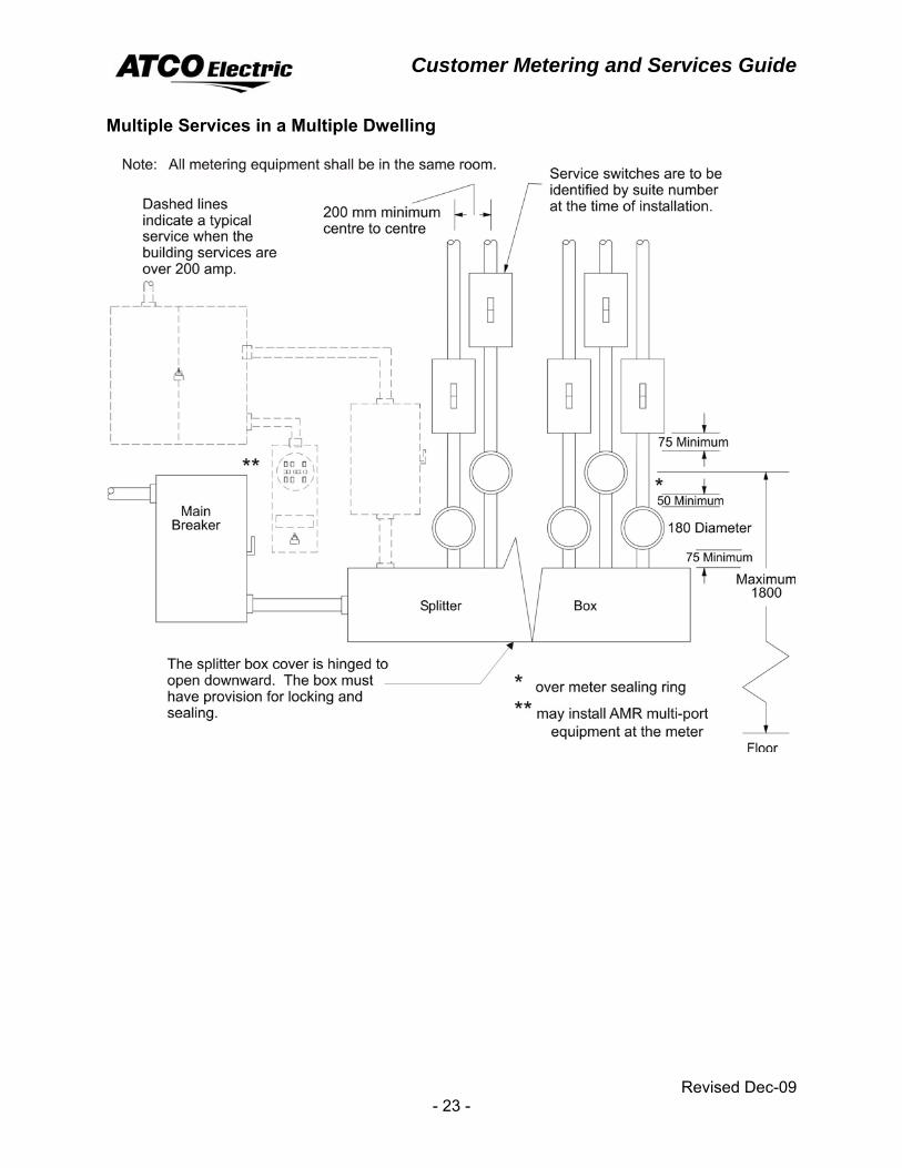
Urban Multiple Residential Dwelling – Metering Single phase urban multiple residential dwellings include apartment buildings, duplexes or fourplexes where there are two or more meters, a main breaker and splitter box on the line side of the meters.
General Requirements ♦ All metering shall be located inside of the building in the same room. Fourplexes,
like duplexes, which have no main breaker ahead of the meters, must have the splitter and meters located together on the outside of the building using outdoor type weatherproof switchgear. Refer to page 23, Multiple Services in a Multiple Dwelling.
♦ For all single phase services, a 4−jaw meter socket shall be used. See page 89, Diagram of Socket Connections.
♦ The meter socket must not have a self shorting device.
♦ For all network services, a 5−jaw meter socket shall be used.
♦ See page 89, Diagram of Socket Connections.
♦ Each individual unit within a multiple dwelling will be served as a separate Point of Service, unless the Company agrees otherwise.
See page 30, Multiple Customer Metering for complexes that are not self-contained.
Single Phase Urban Residential Multiple Dwelling Services from an Overhead Transformer The Customer shall:
• Supply and install a CSA approved low voltage, socket type meter base.
• Supply and install conduit, weatherhead, rack and conductor in the mast on the line side of the main breaker.
• Supply and install the main breaker, conductor and splitter box.
• Supply and install all wiring, equipment and facilities on the load side of the meter.
The Company shall: • Supply and install all facilities required for electrical service up to the weatherhead
including:
• Conductors and connectors from pole to mast.
• Supply and install the meter.
Customer Metering and Services Guide
Revised Dec-09 - 21 -
Urban Residential Multiple Dwelling − Underground Service The Customer shall:
• Supply and install a CSA approved low voltage, socket type meter base.
• Supply and install the conduit and conductors from the service pedestal to the main breaker. Refer to drawing on page 22, Underground Residential Pedestal, Service and Cable Stubbing Arrangement.
• Supply and install the main breaker, conductor and splitter box.
• Supply and install all wiring, equipment and facilities on the load side of the meter.
• Supply under ground secondary service conductors for services greater than 100 Amps.
The Company shall: • Supply and install all facilities required for electrical service up to the meter base
for services up to 100 Amps including:
• Conductors and connectors from service pedestal or transformer to the building.
• Supply and install the meter.
Customer Metering and Services Guide
Revised Dec-09 - 22 -
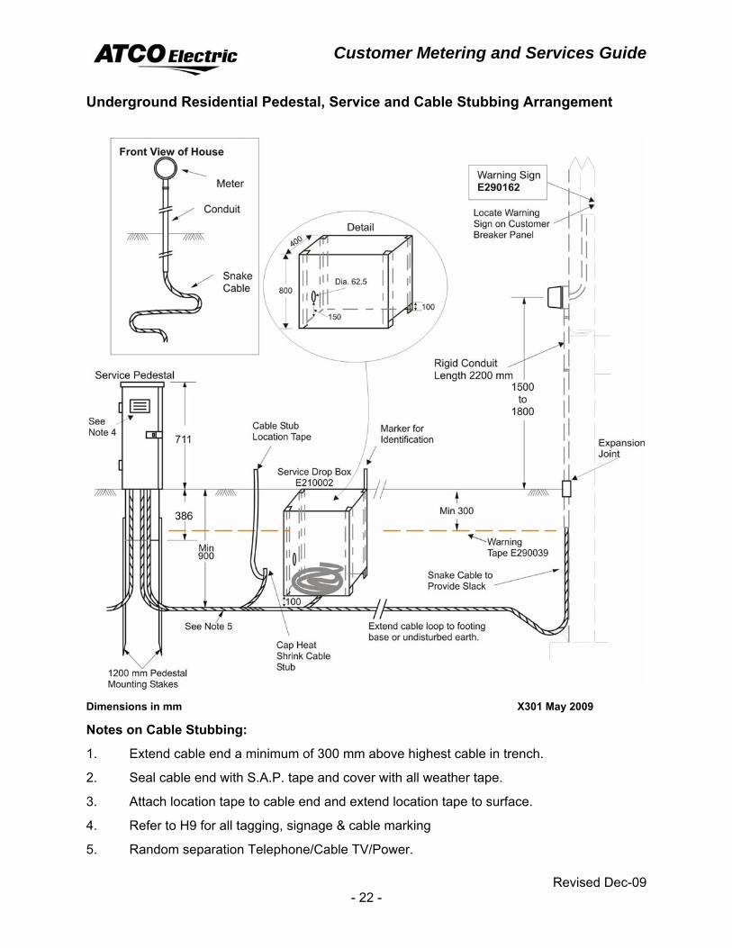
Underground Residential Pedestal, Service and Cable Stubbing Arrangement
Dimensions in mm X301 May 2009
Notes on Cable Stubbing:
1. Extend cable end a minimum of 300 mm above highest cable in trench.
2. Seal cable end with S.A.P. tape and cover with all weather tape.
3. Attach location tape to cable end and extend location tape to surface.
4. Refer to H9 for all tagging, signage & cable marking
5. Random separation Telephone/Cable TV/Power.
Customer Metering and Services Guide
Revised Dec-09 - 23 -
Multiple Services in a Multiple Dwelling
Customer Metering and Services Guide
Revised Dec-09 - 24 -
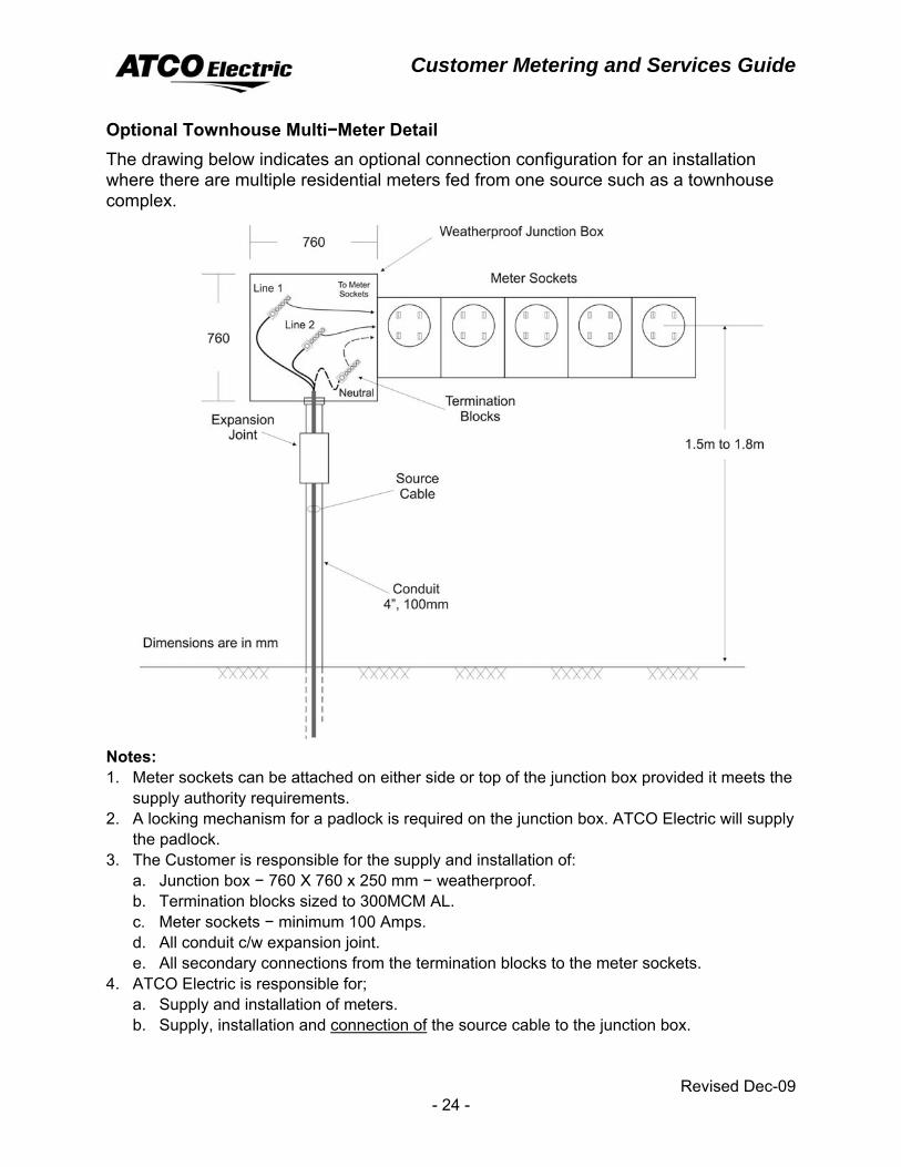
Optional Townhouse Multi−Meter Detail The drawing below indicates an optional connection configuration for an installation where there are multiple residential meters fed from one source such as a townhouse complex.
Notes: 1. Meter sockets can be attached on either side or top of the junction box provided it meets the
supply authority requirements. 2. A locking mechanism for a padlock is required on the junction box. ATCO Electric will supply
the padlock. 3. The Customer is responsible for the supply and installation of:
a. Junction box − 760 X 760 x 250 mm − weatherproof. b. Termination blocks sized to 300MCM AL. c. Meter sockets − minimum 100 Amps. d. All conduit c/w expansion joint. e. All secondary connections from the termination blocks to the meter sockets.
4. ATCO Electric is responsible for; a. Supply and installation of meters. b. Supply, installation and connection of the source cable to the junction box.
Customer Metering and Services Guide
Revised Dec-09 - 25 -
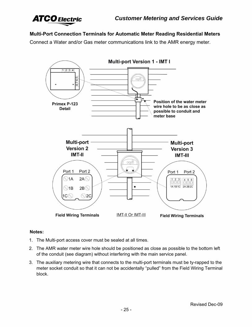
Multi-Port Connection Terminals for Automatic Meter Reading Residential Meters Connect a Water and/or Gas meter communications link to the AMR energy meter.
Notes:
1. The Multi-port access cover must be sealed at all times.
2. The AMR water meter wire hole should be positioned as close as possible to the bottom left of the conduit (see diagram) without interfering with the main service panel.
3. The auxiliary metering wire that connects to the multi-port terminals must be ty-rapped to the meter socket conduit so that it can not be accidentally “pulled” from the Field Wiring Terminal block.
Customer Metering and Services Guide
Revised Dec-09 - 26 -
Overhead Rural Residential Service The Customer shall:
• Supply and install a CSA approved low voltage, socket type meter base.
• Supply and install conduit, weatherhead, rack and conductor in the mast on the line side of the main breaker for a service on a building.
• Supply and install all wiring, equipment and facilities on the load side of the meter.
The Company shall: • Supply and install all facilities required for electrical service up to the weatherhead
including:
• Conductors and connectors from pole to the mast.
• Supply and install the meter.
Customer Metering and Services Guide
Revised Dec-09 - 27 -
Underground Rural Residential Service General Requirements ♦ Refer to page 39, Padmount Transformer and Underground Service on a Farm.
♦ The meter socket must not have self shorting devices.
The Customer shall: • Supply and install a CSA approved low voltage, socket type meter base.
• Supply and install the conduit for the Company's conductors to the meter socket on the line side. Refer to drawing on page 22, Underground Residential Pedestal, Service and Cable Stubbing Arrangement
• Supply under ground secondary service conductors for services greater than 100 Amps.
• Supply and install all wiring, equipment and facilities on the load side of the meter.
The Company shall: • Supply and install all facilities required for electrical service up to the meter base
for services up to 100 Amps including:
• Conductors and connectors from service pedestal or transformer to the building.
• Supply and install the meter.
Overhead to Underground Rural Residential Service When a Customer requests an underground service from an overhead supply, the Customer shall be responsible for all costs incurred by the Company.
Customer Metering and Services Guide
Revised Dec-09 - 28 -
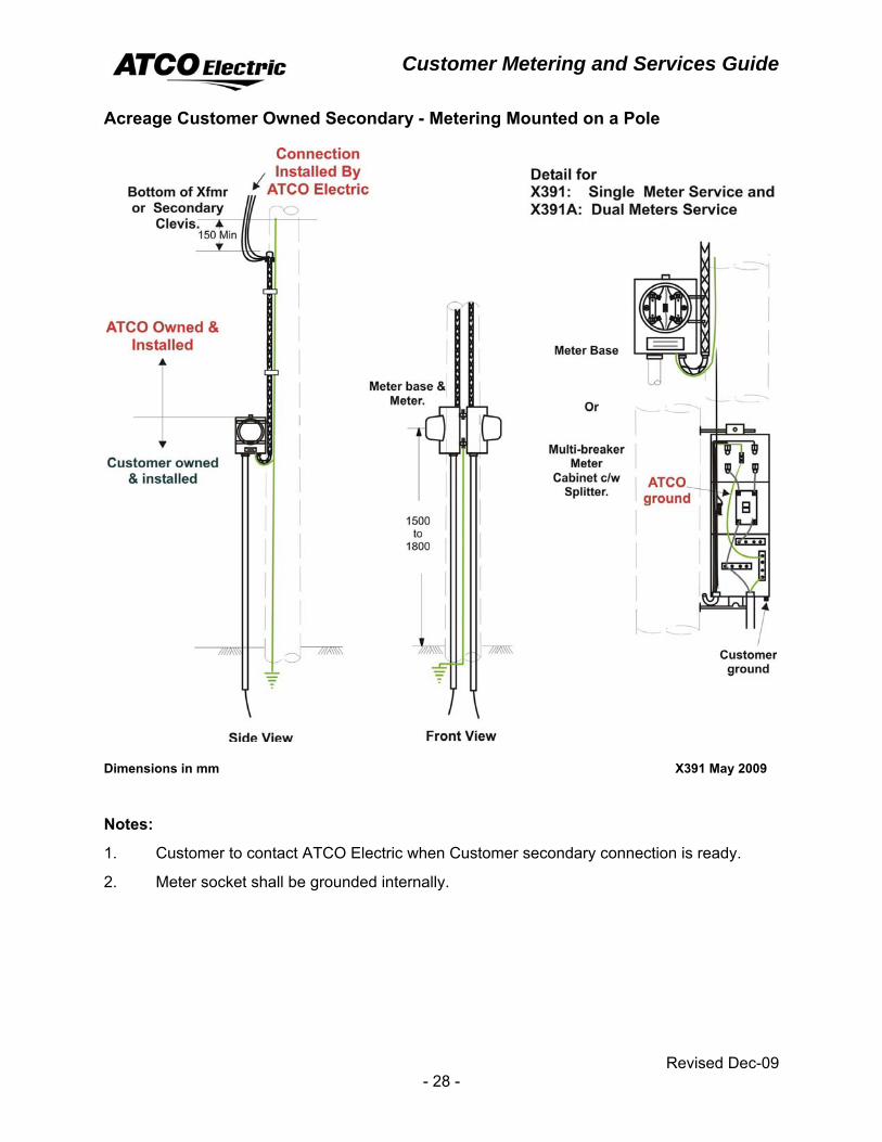
Acreage Customer Owned Secondary - Metering Mounted on a Pole
Dimensions in mm X391 May 2009
Notes:
1. Customer to contact ATCO Electric when Customer secondary connection is ready.
2. Meter socket shall be grounded internally.
Customer Metering and Services Guide
Revised Dec-09 - 29 -
Single Phase Residential Services − Instrument Transformer Metering Single phase instrument transformer metering is used for residential services where the main breaker rating exceeds 200 amperes. Metering shall be located on the load side of the Customer's main breaker.
General Requirements ♦ Metered and unmetered cable shall not be installed in the same auxiliary gutter or
splitter box. There shall be no elbows with covers (LB's) or pull boxes between the instrument transformer cabinet and the meter socket.
♦ The meter shall be located on the inside of a building in the same room as the instrument transformer enclosure, separated by a maximum of 6.5 metres. If the meter cannot be accommodated inside the building, it may be located outside using a Microlectric FA4B-6T, 6 jaw meter socket & test switch enclosure that houses 2 – 2 wire current transformers.
♦ For all single phase instrument services, a 6−jaw meter socket and test switch enclosure shall be used. See page 78, Meter and Test Switch Enclosures – Diagram (1).
♦ Refer to page 75, INSTRUMENT TRANSFORMERS for additional information.
Overhead Service >200 Amps The Customer shall:
• Supply and install a CSA approved low voltage; six jaw meter socket and test switch enclosure.
• Supply and install the conduit, weatherhead, rack and conductors in the mast for metering located on or in a building.
• Supply and install all wiring, equipment and facilities on the load side of the meter.
• Supply and install a Company approved instrument transformer enclosure. See page 76, Meter Requiring Instrument Transformers.
• Be responsible for the installation and primary connection to the current transformer (lugs).
The Company shall: • Supply and install the primary facilities required for electrical service.
• Supply secondary service conductors.
• Supply the current transformers.
• Supply and install the meter.
Customer Metering and Services Guide
Revised Dec-09 - 30 -
Multiple Customer Metering Multiple Customer Metering is used in apartment and condominium buildings where the developer decides not to use the traditional “meter room” that houses all the “suite” and “house” meters for the building.
It consists of a main meter head and junction box connected to “mini” window type current transformers on the branch circuits to the suites.
General Requirements ♦ The supply authority approved; multiple Customer metering is the “miniCloset”
supplied by Quadlogic Meters Canada Inc.
♦ Consult Metering Services to ensure the metering transponder, meter head, current transformer shorting block and current transformers are mounted in the correct location.
♦ All wiring and installation requirements must conform to the Canadian Electrical Code.
♦ Refer to the drawing on page 32, “Typical Arrangement for Multiple Customer Metering” for additional information.
♦ The Customer shall supply the utility engineering department with 3 sets of drawings for the installation of the project. These drawings are to include the electrical connection schematics for the current transformers and all associated panels.
♦ Maintain 1.0 metre clearance on each side of the cabinets for access.
Customer Metering and Services Guide
Revised Dec-09 - 31 -
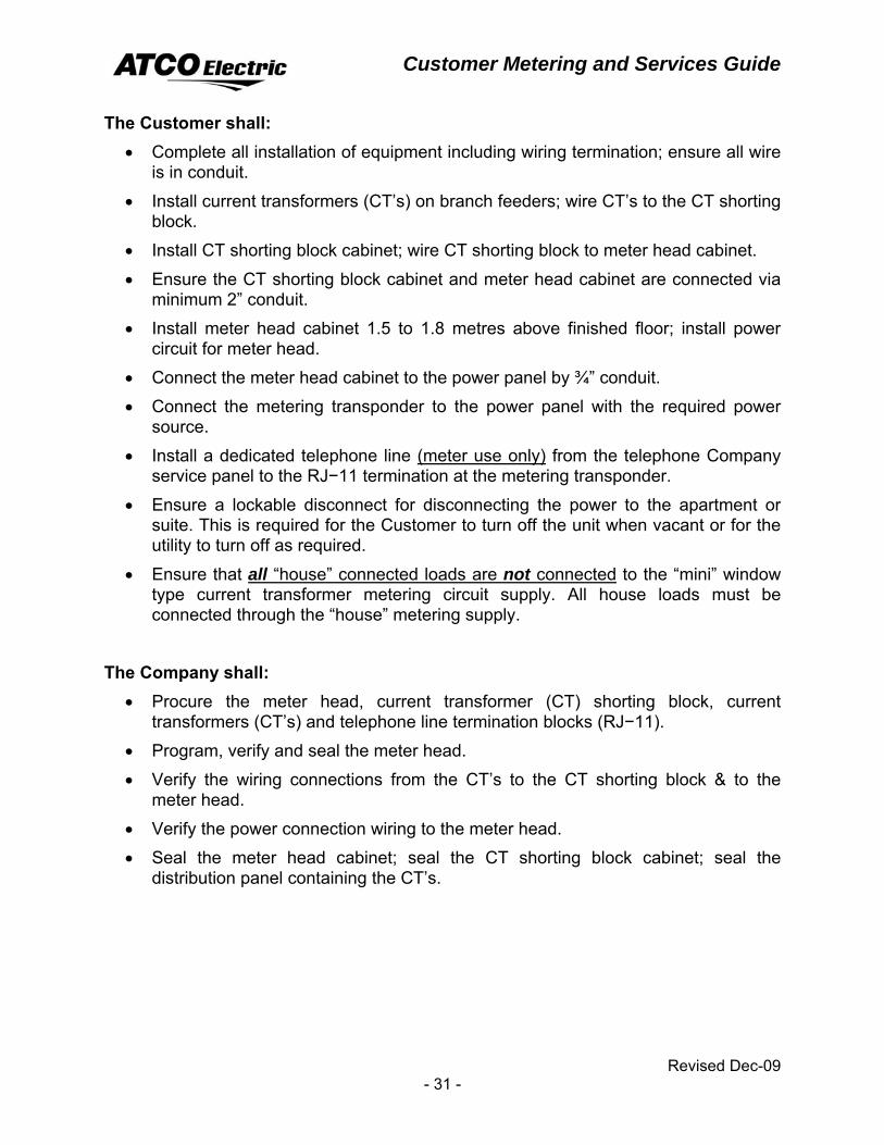
The Customer shall: • Complete all installation of equipment including wiring termination; ensure all wire
is in conduit.
• Install current transformers (CT’s) on branch feeders; wire CT’s to the CT shorting block.
• Install CT shorting block cabinet; wire CT shorting block to meter head cabinet.
• Ensure the CT shorting block cabinet and meter head cabinet are connected via minimum 2” conduit.
• Install meter head cabinet 1.5 to 1.8 metres above finished floor; install power circuit for meter head.
• Connect the meter head cabinet to the power panel by ¾” conduit.
• Connect the metering transponder to the power panel with the required power source.
• Install a dedicated telephone line (meter use only) from the telephone Company service panel to the RJ−11 termination at the metering transponder.
• Ensure a lockable disconnect for disconnecting the power to the apartment or suite. This is required for the Customer to turn off the unit when vacant or for the utility to turn off as required.
• Ensure that all “house” connected loads are not connected to the “mini” window type current transformer metering circuit supply. All house loads must be connected through the “house” metering supply.
The Company shall:
• Procure the meter head, current transformer (CT) shorting block, current transformers (CT’s) and telephone line termination blocks (RJ−11).
• Program, verify and seal the meter head.
• Verify the wiring connections from the CT’s to the CT shorting block & to the meter head.
• Verify the power connection wiring to the meter head.
• Seal the meter head cabinet; seal the CT shorting block cabinet; seal the distribution panel containing the CT’s.
Customer Metering and Services Guide
Revised Dec-09 - 32 -
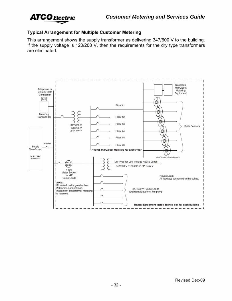
Typical Arrangement for Multiple Customer Metering This arrangement shows the supply transformer as delivering 347/600 V to the building. If the supply voltage is 120/208 V, then the requirements for the dry type transformers are eliminated.
Customer Metering and Services Guide
Revised Dec-09 - 33 -
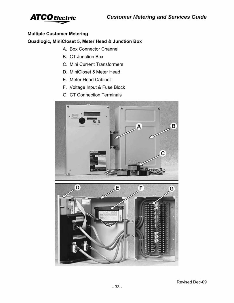
Multiple Customer Metering Quadlogic, MiniCloset 5, Meter Head & Junction Box
A. Box Connector Channel
B. CT Junction Box
C. Mini Current Transformers
D. MiniCloset 5 Meter Head
E. Meter Head Cabinet
F. Voltage Input & Fuse Block
G. CT Connection Terminals

Customer Metering and Services Guide
Revised Dec-09 - 34 -
Customer Metering and Services Guide
Revised Dec-09 - 35 -
FARM SERVICES Farm services are generally services supplying farming operations in a rural area. The system, up to the point of metering, is owned either by the Company or the Rural Electrification Area Limited.
Farm and R.E.A.L. installations not covered by this guide will be handled by the local Company office.
General Requirements ♦ Pole metering is the standard for Farm and R.E.A.L. services.
♦ With the Company’s approval an REA Customer may install a main breaker and meter socket on a building.
♦ Where recessed metering is installed in a wall, a clear space of not less than 0.2 metres on either side of the centre line of the meter base and 1.0 metre in front of the meter is required, to provide the Company access to the meters.
♦ The centre line of the meter socket shall be 1.5 to 1.8 metres above the finished grade or permanent platform.
♦ The meter socket must not have a self shorting device.
Customer Metering and Services Guide
Revised Dec-09 - 36 -
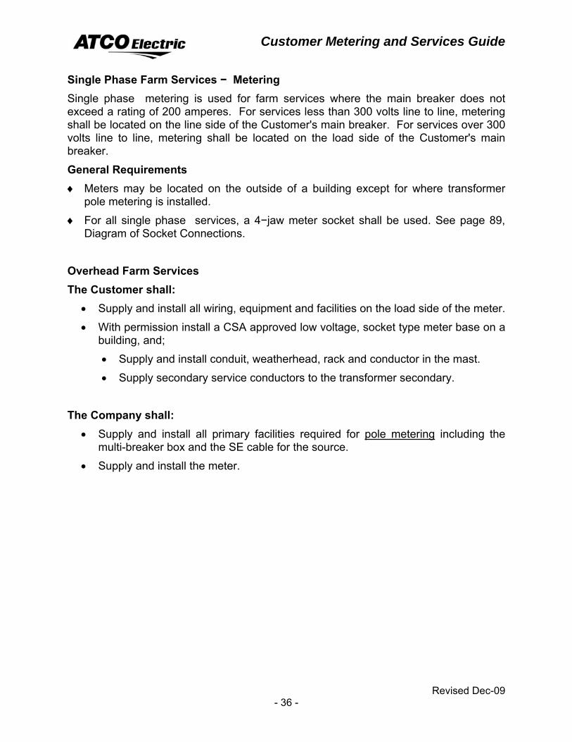
Single Phase Farm Services − Metering Single phase metering is used for farm services where the main breaker does not exceed a rating of 200 amperes. For services less than 300 volts line to line, metering shall be located on the line side of the Customer's main breaker. For services over 300 volts line to line, metering shall be located on the load side of the Customer's main breaker.
General Requirements ♦ Meters may be located on the outside of a building except for where transformer
pole metering is installed.
♦ For all single phase services, a 4−jaw meter socket shall be used. See page 89, Diagram of Socket Connections.
Overhead Farm Services The Customer shall:
• Supply and install all wiring, equipment and facilities on the load side of the meter.
• With permission install a CSA approved low voltage, socket type meter base on a building, and;
• Supply and install conduit, weatherhead, rack and conductor in the mast.
• Supply secondary service conductors to the transformer secondary.
The Company shall: • Supply and install all primary facilities required for pole metering including the
multi-breaker box and the SE cable for the source.
• Supply and install the meter.
Customer Metering and Services Guide
Revised Dec-09 - 37 -
Underground Farm Service The Customer shall:
• Supply and install the conduit for the Company's conductors to the meter socket on the line side. Refer to drawing on page 22, Underground Residential Pedestal, Service and Cable Stubbing Arrangement.
• Supply and install the secondary service conductors from service pedestal or transformer to the building. Connectors shall have NEMA spacing for connection to a spade terminal.
• Supply and install all wiring, equipment and facilities on the load side of the meter.
The Company shall: • supply and install the primary facilities required for electrical service including the
underground metering pedestal, the line side underground cable and the breaker.
• supply and install the meter.
Customer Metering and Services Guide
Revised Dec-09 - 38 -
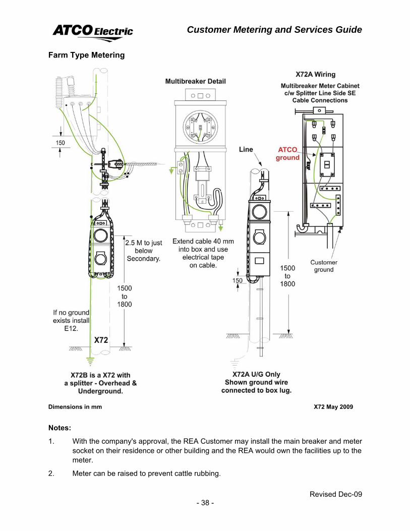
Farm Type Metering
Dimensions in mm X72 May 2009
Notes:
1. With the company's approval, the REA Customer may install the main breaker and meter socket on their residence or other building and the REA would own the facilities up to the meter.
2. Meter can be raised to prevent cattle rubbing.
Customer Metering and Services Guide
Revised Dec-09 - 39 -
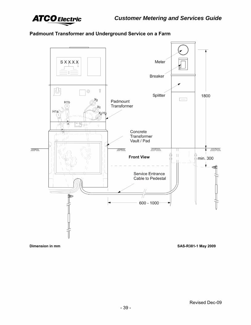
Padmount Transformer and Underground Service on a Farm
Dimension in mm SAS-R381-1 May 2009
Customer Metering and Services Guide
Revised Dec-09 - 40 -
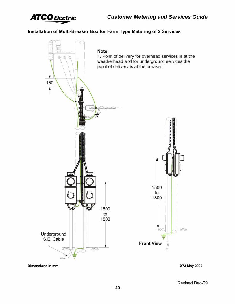
Installation of Multi-Breaker Box for Farm Type Metering of 2 Services
Dimensions in mm X73 May 2009
Customer Metering and Services Guide
Revised Dec-09 - 41 -
Single Phase Farm Services − Instrument Transformer Metering Instrument transformer metering is used for farm services where the main breaker exceeds a rating of 200 amperes. Metering shall be on the load side of the Customer's breaker.
General Requirements ♦ Metered and unmetered cable shall not be installed in the same auxiliary gutter or
splitter box. There shall be no elbows with covers (LB's) or pull boxes between the instrument transformer cabinet and the meter socket.
♦ The meter shall be located on the inside of a building in the same room as the instrument transformer enclosure, separated by a maximum of 6.5 metres. If the meter cannot be accommodated inside the building, it may be located outside using a Microlectric FA4B−6T , 6 jaw meter socket & test switch enclosure that houses 2 – 2 wire current transformers.
♦ For all single phase instrument services, a 6−jaw meter socket and test switch enclosure shall be used. See page 78, Meter and Test Switch Enclosures – (1).
♦ Refer to page 75, INSTRUMENT TRANSFORMERS for additional information.
Overhead Farm Service >200 Amps The Customer shall:
• Supply and install a CSA approved low voltage; six jaw meter socket and test switch enclosure.
• Supply and install the conduit, weatherhead, rack and conductors in the mast for metering located on or in a building.
• Supply secondary service conductors.
• Supply and install all wiring, equipment and facilities on the load side of the meter.
• Supply and install a Company approved instrument transformer enclosure. See page 76, Meter Requiring Instrument Transformers.
• Be responsible for the installation and primary connection to the current transformer (lugs).
The Company shall: • Supply and install the primary facilities required for electrical service.
• Supply the current transformers.
• Supply and install the meter.
Customer Metering and Services Guide
Revised Dec-09 - 42 -
Underground Farm Service >200 Amps The Customer shall:
• Supply and install a CSA approved low voltage; six jaw meter socket and test switch enclosure.
• Supply and install a Company approved instrument transformer enclosure. See page 76, Meter Requiring Instrument Transformers.
• Supply and install all wiring, equipment and facilities on the load side of the meter.
• Supply and install the secondary service conductors from the service pedestal or transformer to the building. Connectors shall have NEMA spacing for connection to a spade terminal.
• Be responsible for the installation and primary connection to the current transformer (lugs).
The Company shall: • Supply and install all facilities required for electrical service up to and including
the service pedestal or padmount transformer.
• Supply the current transformers.
• Supply and install the meter.
Customer Metering and Services Guide
Revised Dec-09 - 43 -
Three Phase Farm Services − Metering Three phase metering is used for farm services where the main breaker rating does not exceed 200 amperes. For services less than 300 volts line to line, metering shall be located on the line side of the Customer's main breaker. For services over 300 volts line to line, metering shall be located on the load side of the Customer's main breaker.
General Requirements ♦ The meter may be inside a MCC electrical building for services over 300 volts line to
line. It may also be at the transformer or service pole.
♦ For three phase services, a 7−jaw meter socket shall be used. See page 90, Diagram of Socket Connections – continued.
♦ The meter socket must not have a self shorting device.
♦ For services over 300 volts line to line the 7−jaw meter socket must have an isolated neutral block.
Overhead and Underground Farm Service The Customer shall:
• supply and install a CSA approved low voltage, socket type meter base.
• supply and install all wiring, equipment and facilities on the load side of the meter.
• for overhead services, supply secondary service conductors.
• for underground services, supply and install all secondary service conductors. Connectors shall have NEMA spacing for connection to a spade terminal.
• complete the secondary cable connections to the transformer secondary bushings of the padmount transformer.
The Company shall: • supply and install the primary facilities required for electrical service.
• connect the service conductors at the transformer pole.
• supply and install the meter.
Customer Metering and Services Guide
Revised Dec-09 - 44 -
Three Phase Farm Services − Instrument Transformer Metering Three phase instrument transformer metering is used for farm services where the main breaker rating exceeds 200 amperes. Metering shall be on the load side of the Customer's breaker.
General Requirements ♦ Metered and unmetered cable shall not be installed in the same auxiliary gutter or
splitter box. There shall be no elbows with covers (LB's) or pull boxes between the instrument transformer cabinet and the meter socket.
♦ The meter shall be located on the inside of a building in the same room as the instrument transformer enclosure, separated by a maximum of 6.5 metres. If the meter cannot be accommodated inside the building, it may be located outside in a weatherproof cabinet. Refer drawing on page 76, Meter Requiring Instrument Transformers.
♦ For all three phase instrument services, a 13−jaw meter socket and test switch enclosure shall be used. See page 78, Meter and Test Switch Enclosures – (2).
♦ Refer to page 75, INSTRUMENT TRANSFORMERS – for additional information.
Customer Metering and Services Guide
Revised Dec-09 - 45 -
Overhead and Underground Farm Services >200 Amps The Customer shall:
• Supply and install an appropriate CSA approved thirteen jaw meter socket and test switch enclosure.
• Supply and install a Company approved instrument transformer enclosure. See page 76, Meter Requiring Instrument Transformers.
• Be responsible for the installation of and primary connection to, the current transformers (lugs) and the installation of the voltage transformers.
• Be responsible for ensuring that the neutral wire is extended into the instrument transformer enclosure.
• Refer to page 80, 3 Phase, 4 Wire 120/208Y Volt Instrument Metering & page 81, 3 Phase, 4 Wire 277/480Y Volt or 3 Phase, 4 Wire 347/600Y Volt Instrument Metering.
• For overhead services, supply secondary service conductors.
• For underground services, supply secondary service conductors. Connectors shall have NEMA spacing for connection to a spade terminal.
• Make the secondary cable connections to the transformer secondary bushings of the padmount transformer.
• Supply and install all wiring, equipment and facilities on the load side of the meter.
The Company shall: • For underground services, supply and install all facilities required for electrical
service up to the padmount transformer.
• Supply current and/or voltage instrument transformers and upon request ship the equipment to the electrical contractor or manufacturer.
• Supply and install the meter.
For the following three phase services or any other services not covered in this guide, see the local ATCO Electric office prior to construction.
Overhead to Underground Farm Service Underground to Overhead Farm Service Underground Service from a Padmount Transformer − Farm Service

Customer Metering and Services Guide
Revised Dec-09 - 46 -
Customer Metering and Services Guide
Revised Dec-09 - 47 -
COMMERCIAL SERVICES Commercial services are typically businesses that provide sales, transportation, packaging, distribution, storage and accounting of goods and services.
General Requirements ♦ Where recessed metering is installed in a wall, a clear space of not less than 0.2
metres on either side of the centre line of the meter base and 1.0 metre in front of the meter is required, to provide the Company access to the meters.
♦ The centre line of the meter socket shall be 1.5 to 1.8 metres above the finished grade or permanent platform and in a properly lighted area.
♦ The meter socket must not have a self shorting device.
Customer Metering and Services Guide
Revised Dec-09 - 48 -
Single Phase Commercial Services − Metering Single phase metering is used for commercial services where the main breaker rating does not exceed 200 amperes. For services less than 300 volts line to line, metering shall be located on the line side of the Customer's main breaker. For services over 300 volts line to line, metering shall be located on the load side of the Customer's main breaker.
General Requirements ♦ Meters shall be located on the outside of a building except for where transformer
pole metering is installed.
♦ For all single phase services, a 4−jaw meter socket shall be used. See page 89, Diagram of Socket Connections.
♦ The meter socket must not have a self shorting device.
Overhead Commercial Service The Customer shall:
• Supply and install a CSA approved low voltage, socket type meter base on the building.
• Supply and install conduit, weatherhead, rack and conductor in the mast for metering located on a building.
• Supply and install all wiring, equipment and facilities on the load side of the meter.
The Company shall: • Supply and install the secondary conductors required for electrical service up to
the weatherhead.
• Supply and install the meter.
• For special applications, such as a Farm Customer going onto a Commercial rate for grain drying, the Company shall supply and install a CSA approved low voltage, socket type meter base for pole metering.
Customer Metering and Services Guide
Revised Dec-09 - 49 -
Underground Commercial Service The Customer shall:
• Supply and install a CSA approved low voltage, socket type meter base.
• Supply and install the conduit for the conductors to the meter socket on the line side.
• Supply and install the secondary service conductors from service pedestal or transformer to the building.
• Make the secondary cable connections to the transformer secondary bushings of the padmount transformer. Connectors shall have NEMA spacing for connection to a spade terminal.
• Supply and install all wiring, equipment and facilities on the load side of the meter.
The Company shall: • Supply and install all facilities required for electrical service up to and including
the service pedestal or padmount transformer.
• Supply and install meter.
Customer Metering and Services Guide
Revised Dec-09 - 50 -
Single Phase Commercial Services − Instrument Transformer Metering Instrument transformer metering is used for commercial services where the main breaker rating exceeds 200 amperes. Metering shall be on the load side of the Customer's breaker.
General Requirements ♦ Metered and unmetered cable shall not be installed in the same auxiliary gutter or
splitter box. There shall be no elbows with covers (LB's) or pull boxes between the instrument transformer cabinet and the meter socket.
♦ The meter shall be located on the inside of a building in the same room as the instrument transformer enclosure, separated by a maximum of 6.5 metres.
♦ If the meter cannot be accommodated inside the building, it may be located outside using a Microlectric FA4B−6T, 6 jaw meter socket & test switch enclosure that houses 2 – 2 wire current transformers.
♦ For all single phase instrument services, a 6−jaw meter socket and test switch enclosure shall be used. See page 78, Meter and Test Switch Enclosures – (1).
♦ Refer to page 75, INSTRUMENT TRANSFORMERS – for additional information.
Customer Metering and Services Guide
Revised Dec-09 - 51 -
Overhead Commercial Service >200 Amps The Customer shall:
• Supply and install a CSA approved low voltage; six jaw meter socket and test switch enclosure.
• Supply and install the conduit, weatherhead, rack and conductors in the mast.
• Supply and install all wiring, equipment and facilities on the load side of the meter.
• Supply and install a Company approved instrument transformer enclosure. See page 76, Meter Requiring Instrument Transformers.
• Be responsible for the installation and primary connection to the current transformer (lugs).
The Company shall: • Supply and install the secondary conductors required for electrical service up to
the weatherhead.
• Supply the current transformers.
• Supply and install the meter.
Customer Metering and Services Guide
Revised Dec-09 - 52 -
Underground Commercial Service >200 Amps The Customer shall:
• Supply and install a CSA approved low voltage; six jaw meter socket and test switch enclosure.
• Supply and install a Company approved instrument transformer enclosure. See page 76, Meter Requiring Instrument Transformers.
• Be responsible for the installation and primary connection to the current transformer (lugs).
• Supply and install secondary service conductors to the transformer. Connectors shall have NEMA spacing for connection to a spade terminal.
• Complete the secondary cable connections to the transformer secondary bushings of the padmount transformer.
• Supply and install all wiring, equipment and facilities on the load side of the meter.
The Company shall: • Supply and install all facilities required for electrical service up to and including
the padmount transformer.
• Supply the current transformers.
• Supply and install the meter.
Customer Metering and Services Guide
Revised Dec-09 - 53 -
Three Phase Commercial Services − Metering Three phase metering is used for commercial services where the main breaker rating does not exceed 200 amperes and 600 volts. For services less than 300 volts line to line, metering shall be located on the line side of the Customer's main breaker. For services over 300 volts line to line, metering shall be located on the load side of the Customer's main breaker.
General Requirements ♦ For three phase services, a 7−jaw meter socket shall be used. See page 90,
Diagram of Socket Connections – continued.
♦ For services over 300 volts line to line the 7−jaw meter socket must have an isolated neutral block as per Canadian Electrical Code.
♦ The meter socket must not have a self shorting device.
♦ The preferred location for 347/600 volt AMR metering is inside of a building.
Overhead and Underground Commercial Service The Customer shall:
• Supply and install a CSA approved low voltage, socket type meter base.
• Supply and install all wiring, equipment and facilities on the load side of the meter.
• For overhead services greater than 150 kVA, supply secondary service conductors.
• For underground services, supply and install secondary service conductors from the meter to the transformer. Connectors shall have NEMA spacing for connection to a spade terminal.
• Make the secondary cable connections to the transformer secondary bushings of the padmount transformer.
The Company shall: • For overhead services up to 150 kVA, supply and install conductors up to the
weatherhead.
• For underground services, supply and install all facilities required for electrical service up to and including the padmount transformer.
• Supply and install the meter.
Customer Metering and Services Guide
Revised Dec-09 - 54 -
Three Phase Commercial Services − Instrument Transformer Metering Three phase instrument transformer metering is used for commercial services where the main breaker rating exceeds 200 amperes and/or 600 volts. Metering shall be on the load side of the Customer's breaker.
General Requirements ♦ Metered and unmetered cable shall not be installed in the same auxiliary gutter or
splitter box. There shall be no elbows with covers (LB's) or pull boxes between the instrument transformer cabinet and the meter socket.
♦ The meter shall be located on the inside of a building or in an outdoor weatherproof cabinet. The instrument transformer enclosure and the meter shall be in the same room, separated by a maximum of 6.5 metres. Refer to on page 76, Meter Requiring Instrument Transformers.
♦ For all three phase services, a 13−jaw meter socket and test switch enclosure shall be used. See page 78, Meter and Test Switch Enclosures – diagram (2).
♦ Refer to page 75, INSTRUMENT TRANSFORMERS – for additional information.
♦ Refer to drawing on page 69, Secondary Overhead to Underground Riser on a Pole
Customer Metering and Services Guide
Revised Dec-09 - 55 -
Overhead and Underground Commercial Services >200 Amps The Customer shall:
• Supply and install an appropriate CSA approved 13 jaw meter socket and test switch enclosure.
• Supply and install a Company approved instrument transformer enclosure. See page 76, Meter Requiring Instrument Transformers.
• Be responsible for the installation of and primary connection to, the current transformers and the installation of the voltage transformers.
• Be responsible for ensuring that the neutral wire is extended into the instrument transformer enclosure.
• Refer to page 80, 3 Phase, 4 Wire 120/208Y Volt Instrument Metering & page 81, 3 Phase, 4 Wire 277/480Y Volt or 3 Phase, 4 Wire 347/600Y Volt Instrument Metering
• For overhead services greater than 150 kVA, extend its supply conductors and provide connectors to the secondary bushings of the Company's supply transformer.
• For underground services, supply and install secondary service conductors up to the transformer. Connectors shall have NEMA spacing for connection to a spade terminal.
• Make the secondary cable connections to the transformer secondary bushings of the padmount transformer.
• Supply and install all wiring, equipment and facilities on the load side of the meter.
The Company shall: • For underground services, supply and install all facilities required for electrical
service up to and including the padmount transformer.
• For overhead services up to 150 kVA, supply and install conductors up to the weatherhead.
• Supply current and voltage instrument transformers and upon request ship the equipment to the electrical contractor or manufacturer.
• Supply and install the meter.
Customer Metering and Services Guide
Revised Dec-09 - 56 -
Customer Metering and Services Guide
Revised Dec-09 - 57 -
INDUSTRIAL SERVICES Industrial services are generally large facilities where the primary function is in oilfield operations, manufacturing and/or producing of a product.
General Requirements ♦ Where recessed metering is installed in a wall, a clear space of not less than 0.2
metres on either side of the centre line of the meter base and 1.0 metre in front of the meter is required, to provide the Company access to the meters.
♦ Metering shall not be located on the pumpjack. Metering shall be located on a remote or separate service pole (i.e.: a service pole or transformer pole) away from the pumpjack.
♦ The centre line of the meter socket shall be 1.5 to 1.8 metres above the finished grade or permanent platform and in a properly lighted area.
♦ The meter socket must not have a self shorting device.
Customer Metering and Services Guide
Revised Dec-09 - 58 -
Single Phase Industrial Services − Metering Single phase metering is used for industrial services where the main breaker rating does not exceed 200 amperes. For services less than 300 volts line to line, metering shall be located on the line side of the Customer's main breaker. For services over 300 volts line to line, metering shall be located on the load side of the Customer's main breaker.
General Requirements ♦ Metering shall be located on the outside of a building except for where transformer
pole metering is installed.
♦ For all single phase services, a 4−jaw meter socket shall be used. See page 89, Diagram of Socket Connections.
♦ The meter socket must not have a self shorting device.
Overhead Industrial Service The Customer shall:
• Supply and install a CSA approved low voltage, socket type meter base on the building.
• Supply and install conduit, weatherhead, rack and conductor in the mast for metering located on a building.
• Supply and install all wiring, equipment and facilities on the load side of the meter.
• The Company shall: • Supply and install the secondary conductors required for electrical service up to
the weatherhead.
• Conductors and connectors from pole to mast.
• Supply and install the meter.
Customer Metering and Services Guide
Revised Dec-09 - 59 -
Underground Industrial Service The Customer shall:
• Supply and install a CSA approved low voltage, socket type meter base.
• Supply and install the conduit for the conductors to the meter socket on the line side.
• Supply and install the secondary service conductors from service pedestal or transformer to the building.
• Make the secondary cable connections to the transformer secondary bushings of the padmount transformer. Connectors shall have NEMA spacing for connection to a spade terminal.
• Supply and install all wiring, equipment and facilities on the load side of the meter.
The Company shall: • Supply and install all facilities required for electrical service up to and including
the service pedestal or padmount transformer.
• Supply and install meter.
Customer Metering and Services Guide
Revised Dec-09 - 60 -
Single Phase Industrial Services − Instrument Transformer Metering Single phase instrument transformer metering is used for industrial services where the main breaker rating exceeds 200 amperes. Metering shall be on the load side of the Customer's breaker. General Requirements
♦ Metered and unmetered cable shall not be installed in the same auxiliary gutter or splitter box. There shall be no elbows with covers (LB's) or pull boxes between the instrument transformer cabinet and the meter socket.
♦ Instrument Transformer cabinets may not be used as junction boxes to connect secondary load conductors.
♦ The meter shall be located on the inside of a building or in an outdoor weatherproof cabinet. The instrument transformer enclosure and the meter shall be in the same room, separated by a maximum of 6.5 metres. Refer to page 76, Meter Requiring Instrument Transformers.
♦ If the meter cannot be accommodated inside the building, it may be located outside using a Microlectric FA4B−6T, 6 jaw meter socket & test switch enclosure that houses 2 – 2 wire current transformers.
♦ For all single phase instrument services, a 6−jaw meter socket and test switch enclosure shall be used. See page 78, Meter and Test Switch Enclosures – (1).
♦ Refer to page 75, INSTRUMENT TRANSFORMERS – for additional information.
Customer Metering and Services Guide
Revised Dec-09 - 61 -
Overhead Industrial Service >200 Amps The Customer shall:
• Supply and install a CSA approved low voltage; six jaw meter socket and test switch enclosure.
• Supply and install the conduit, weatherhead, rack and conductors in the mast.
• Supply and install all wiring, equipment and facilities on the load side of the meter.
• Supply and install a Company approved instrument transformer enclosure. See page 76, Meter Requiring Instrument Transformers.
• Be responsible for the installation and primary connection to the current transformer.
The Company shall: • Supply and install the secondary conductors required for electrical service up to
the weatherhead.
• Supply the current transformer.
• Supply and install the meter.
Customer Metering and Services Guide
Revised Dec-09 - 62 -
Underground Industrial Service >200 Amps The Customer shall:
• Supply and install a CSA approved low voltage; six jaw meter socket and test switch enclosure.
• Supply and install a Company approved instrument transformer enclosure. Refer to page 75, INSTRUMENT TRANSFORMERS − for additional information.
• Be responsible for the installation and primary connection to the current transformer.
• Supply and install the secondary service conductors to the transformer. Connectors shall have NEMA spacing for connection to a spade terminal.
• Make the secondary cable connections to the transformer secondary bushings of the padmount transformer.
• Supply and install all wiring, equipment and facilities on the load side of the meter.
The Company shall: • Supply and install all facilities required for electrical service up to and including
the padmount transformer.
• Supply the current transformer.
• Supply and install the meter.
Customer Metering and Services Guide
Revised Dec-09 - 63 -
Three Phase Industrial Services − Metering Three phase metering is used for industrial services where the main breaker rating does not exceed 225 amperes and a voltage of 600 volts. For services less than 300 volts line to line, metering shall be located on the line side of the Customer's main breaker. For services over 300 volts line to line, metering shall be located on the load side of the Customer's main breaker.
General Requirements ♦ The metering may be pole, panel or inside a MCC electrical building, depending on
the type of Customer application.
♦ For three phase services, a 7−jaw meter socket shall be used. See page 90, Diagram of Socket Connections – continued. This includes oilfield services.
♦ The meter socket must not have a self shorting device.
♦ For services over 300 volts line to line the 7−jaw meter socket must have an isolated neutral block as per Canadian Electrical Code.
♦ The preferred location for 347/600 volt AMR metering is inside of a MCC building.
Overhead and Underground Industrial Service The Customer shall:
• Supply and install a CSA approved low voltage, socket type meter base.
• Supply and install all wiring, equipment and facilities on the load side of the meter.
• For overhead services greater than 150 kVA, extend its supply conductors and provide connectors to the secondary bushings of the Company's supply transformer.
• For underground services, supply and install secondary service conductors from the meter to the transformer. Connectors shall have NEMA spacing for connection to a spade terminal.
• Make the secondary cable connections to the transformer secondary bushings of the padmount transformer.
The Company shall: • For overhead services up to 150 kVA, supply and install conductors up to the
weatherhead.
• For underground services, supply and install all facilities required for electrical service up to and including the padmount transformer.
• Supply and install the meter.
Customer Metering and Services Guide
Revised Dec-09 - 64 -
Three Phase Industrial Services − Instrument Transformer Metering Three phase instrument transformer metering is used for industrial services where the main breaker rating exceeds 225 amperes and/or 600 volts. Metering shall be on the load side of the Customer's breaker.
General Requirements ♦ Metered and unmetered cable shall not be installed in the same auxiliary gutter or
splitter box. There shall be no elbows with covers (LB's) or pull boxes between the instrument transformer cabinet and the meter socket.
♦ Instrument Transformer cabinets may not be used as junction boxes to connect secondary load conductors.
♦ The meter(s) shall be located on the inside of a building in the same room as the instrument transformer enclosure, separated by a maximum of 6.5 metres. If the meter cannot be accommodated inside the building, it may be located outside in a weatherproof cabinet. Refer to page 76, Meter Requiring Instrument Transformers.
♦ For all three phase instrument services, a 13−jaw meter socket and test switch enclosure shall be used. See page 78, Meter and Test Switch Enclosures – (2).
♦ Refer to page 75, INSTRUMENT TRANSFORMERS, for additional information.
♦ Refer to drawing on page 69, Secondary Overhead to Underground Riser on a Pole.
Customer Metering and Services Guide
Revised Dec-09 - 65 -
Overhead and Underground Industrial Services >200 Amps The Customer shall:
• Supply and install an appropriate CSA approved 13 jaw meter socket and test switch enclosure.
• Supply and install a Company approved instrument transformer enclosure. See page 76, Meter Requiring Instrument Transformers.
• Be responsible for the installation of and primary connection to, the current transformers and the installation of the voltage transformers.
• Be responsible for ensuring that the neutral wire is extended into the instrument transformer enclosure.
• Refer to page 80, 3 Phase, 4 Wire 120/208Y Volt Instrument Metering & page 81, 3 Phase, 4 Wire 277/480Y Volt or 3 Phase, 4 Wire 347/600Y Volt Instrument Metering
• For overhead services greater than 150 kVA, extend its supply conductors to the secondary bushings of the Company's supply transformer.
• For underground services, supply secondary service conductors from the meter to the transformer. Connectors shall have NEMA spacing for connection to a spade terminal.
• Make the secondary cable connections to the transformer secondary bushings of the padmount transformer.
• Supply and install all wiring, equipment and facilities on the load side of the meter.
The Company shall: • For underground services, supply and install all facilities required for electrical
service up to and including the padmount transformer.
• For overhead services up to 150 kVA, supply and install conductors up to the weatherhead.
• Supply current and voltage instrument transformers and upon request ship the equipment to the electrical contractor or manufacturer.
• Supply and install the meter.
Customer Metering and Services Guide
Revised Dec-09 - 66 -
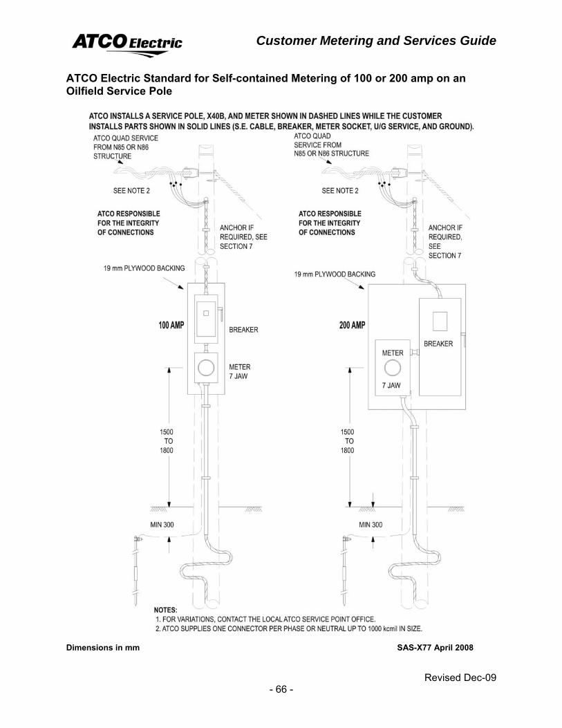
ATCO Electric Standard for Self-contained Metering of 100 or 200 amp on an Oilfield Service Pole
Dimensions in mm SAS-X77 April 2008
Customer Metering and Services Guide
Revised Dec-09 - 67 -
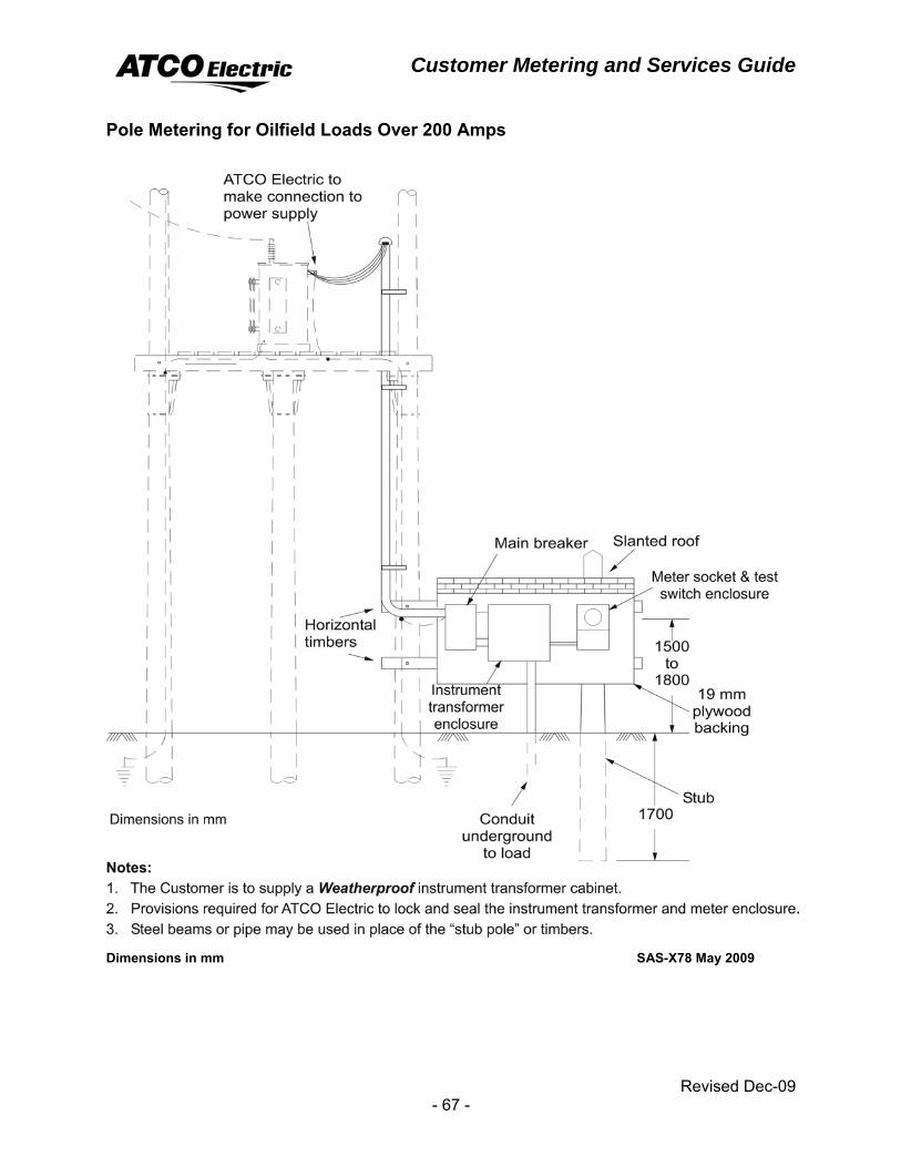
Pole Metering for Oilfield Loads Over 200 Amps
Dimensions in mm SAS-X78 May 2009
Customer Metering and Services Guide
Revised Dec-09 - 68 -
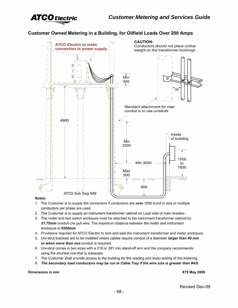
Customer Owned Metering in a Building, for Oilfield Loads Over 200 Amps
Dimensions in mm X79 May 2009
Customer Metering and Services Guide
Revised Dec-09 - 69 -
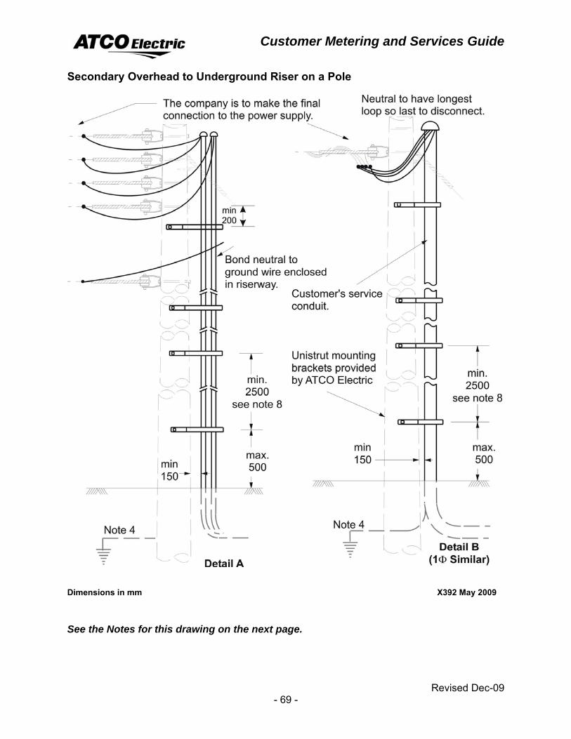
Secondary Overhead to Underground Riser on a Pole
Dimensions in mm X392 May 2009
See the Notes for this drawing on the next page.
Customer Metering and Services Guide
Revised Dec-09 - 70 -
Notes: 1. Customer is to supply connectors if conductors over 1000 kcmil in size or
multiple conductors per phase are used.
2. Cover all connections with all weather tape or proper covers.
3. Vertical conductors attached to a pole must be suitably protected. If the riser cannot be placed where interference from vehicular traffic or pedestrian activity will be minimal. Steel posts, concrete curbs or other approved means must be used to protect the facilities.
4. ATCO Electric recommends Customer install a ground at pole so no neutral current from ATCO Electric circuit will flow to Customer's ground at main breaker.
5. All Customers’ cable including single phase similar to Detail B must be mounted on unistrut mounting brackets with the exception of X390 and X391.
6. Unistrut comes in two sizes with a 216 or 381mm stand-off arm and the company recommends using the shortest that is adequate.
7. Unistrut mounting brackets will be provided by ATCO Electric.
8. Rigid PVC or HFT conduit with a trade size of 2 1/2 or larger will be acceptable with spacing between supports of 2.5 m, at one point only.
9. ATCO Electric will locate Customer underground cable on a Customer’s property. Agreement should be obtained that ATCO Electric is not liable for any dig ins as the cable was installed and mapped by the Customer.
10. Tech. Cable to be installed in rigid conduit. To avoid risers slipping through the conduit, the risers should be planted firmly on the ground or clamped to an approved cable tray.
Customer Metering and Services Guide
Revised Dec-09 - 71 -
MICRO−GENERATION Micro-Generation is defined as a generating unit that has a total nominal capacity of one megawatt or less, exclusively uses sources of renewable or alternative energy, is intended to meet all or a portion of the Customer’s electricity needs, connects to the distribution system and is located on the Customer’s site or on a site owned by or leased to the Customer that is adjacent to the Customer’s site. Micro-Generation units must use electricity generated by a renewable or alternative energy that is environmentally friendly fuel source such as solar panels, small-scale hydro, wind, biomass and fuel cells.
General Requirements ♦ The Customer must comply with the “Application for Service & General
Requirements” of this guide for the required service type.
♦ The Customer is responsible for obtaining the electrical permit, any municipal approvals and making commercial arrangements with a Retailer.
♦ The Customer must complete the application process requirement found on the ATCO Electric web site (www.atcoelectric.com). Further information is available at Alberta Utilities Commission at auc.ab.ca.
♦ The Company must post a warning label indicating the existence of dual voltage supply adjacent to the meter(s).
Mini Micro-Generation Mini micro-generation is defined as a generating unit which is using an inverter and has a generation capacity of no more than 10kW and is generating electric energy solely for the Customer’s own use.
The Customer is: • Required to meet with ATCO Electric to ensure the service connection details follow
the Alberta Utilities Commission guidelines and the Supply Authority requirements.
The Company shall: • Supply and install meter(s).
Customer Metering and Services Guide
Revised Dec-09 - 72 -
Small Micro-Generation Small micro-generation is defined as a generating unit of a normal capacity of less than 150 kW.
The Customer is: • Required to meet with ATCO Electric to ensure the service connection details follow
the Alberta Utilities Commission guidelines and the Supply Authority requirements.
The Company shall: • Supply and install meter(s).
Large Micro-Generation Large micro-generation is defined as a generating unit of a normal capacity of at least 150 kW, but not exceeding 1 MW.
The Customer is: • Required to meet with ATCO Electric to ensure the service connection details follow
the Alberta Utilities Commission guidelines and the Supply Authority requirements.
The Company shall: • Supply and install the meter(s).
Customer Metering and Services Guide
Revised Dec-09 - 73 -
TEMPORARY SERVICES & IDLE SERVICES
Temporary Services Temporary service normally means service that will be required for two years or less. In some cases, a longer period may be appropriate if both the Company and the Customer know that the Customer has no intention of remaining on-site permanently. For example, road construction camps sometimes require service for three years while they are constructing a project such as a stretch of highway.
To determine whether a service is temporary contact your local Company office.
Idle Services An idle service normally means a service that has been temporary disconnected for a period of six to twelve months. The meter will normally have a disconnect sleeve connected or the metering and associated facilities such as the transformer may be temporarily removed. During the idle service period, the Customer will be billed on the greater of the contract minimum as agreed upon in their Electric Service Agreement or the rate minimum.
For service reconnection contact the local ATCO Electric office.
The local Company office or marketing representative can provide further details on idle services.
The Retailer may hold all wires related charges until the service is reconnected. The sum of the wires charges will then be passed on to the Customer.

Customer Metering and Services Guide
Revised Dec-09 - 74 -
Customer Metering and Services Guide
Revised Dec-09 - 75 -
INSTRUMENT TRANSFORMERS ATCO Electric metering services, through a meter technologist or the local service office, will supply current and voltage instrument transformers. Upon request, the Company will ship the equipment to the electrical contractor or manufacturer.
The Customer is responsible for the installation and primary connection of the current transformers and for the installation of the voltage transformers.
Instrument Transformer Enclosures The Customer must provide and install a Company approved instrument transformer enclosure.
On three phase installations the Customer is responsible for ensuring that the neutral wire and all phase wires are connected inside the instrument transformer enclosure.
Instrument transformer metering requires a combination meter socket base and test switch enclosure. Only socket type meters are approved for metering within ATCO Electric.
Refer to:
page 78, Meter and Test Switch Enclosures
page 80, 3 Phase, 4W 120/208Y Volt Instrument Metering
page 81, 3 Phase, 4 W 277/480Y or 347/600Y Volt Instrument Metering
The Customer shall supply and install either a 6−jaw meter socket and test switch enclosure, in the case of single−phase services, or a 13−jaw meter socket and test switch enclosure, in the case of three−phase services.
A clear space of one metre is required in front of the enclosure. The Company will place a decal label on the outside of the instrument transformer enclosure door. A minimum clearance of 600 mm shall be maintained to pass by the edge of the door of the enclosure which in the open position would block an exit route.
The instrument transformer enclosure shall have a minimum inside dimension of 760 x 760 x 250 mm (length x width x depth). The diagram on page 85 shows Window Type Current Transformer, 700V Class for larger loads and on page 87 the specifications for larger instrument transformer enclosures are given.
Indoor installation: double, vertically−hinged doors which swing open at least 110 degrees or a single−hinged door are acceptable. If the cabinet is in a high dust area it must be a single weatherproof door type.
Outdoor installation: the instrument transformer cabinet must have a single weatherproof door.
Enclosures for instrument transformers, meters and test switches shall have provisions for locking and sealing.
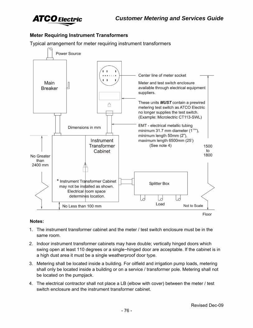
Customer Metering and Services Guide
Revised Dec-09 - 76 -
Meter Requiring Instrument Transformers Typical arrangement for meter requiring instrument transformers
Notes:
1. The instrument transformer cabinet and the meter / test switch enclosure must be in the same room.
2. Indoor instrument transformer cabinets may have double; vertically hinged doors which swing open at least 110 degrees or a single−hinged door are acceptable. If the cabinet is in a high dust area it must be a single weatherproof door type.
3. Metering shall be located inside a building. For oilfield and irrigation pump loads, metering shall only be located inside a building or on a service / transformer pole. Metering shall not be located on the pumpjack.
4. The electrical contractor shall not place a LB (elbow with cover) between the meter / test switch enclosure and the instrument transformer cabinet.
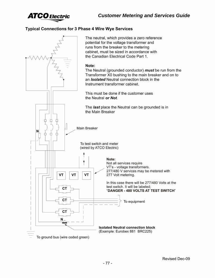
Customer Metering and Services Guide
Revised Dec-09 - 77 -
Typical Connections for 3 Phase 4 Wire Wye Services
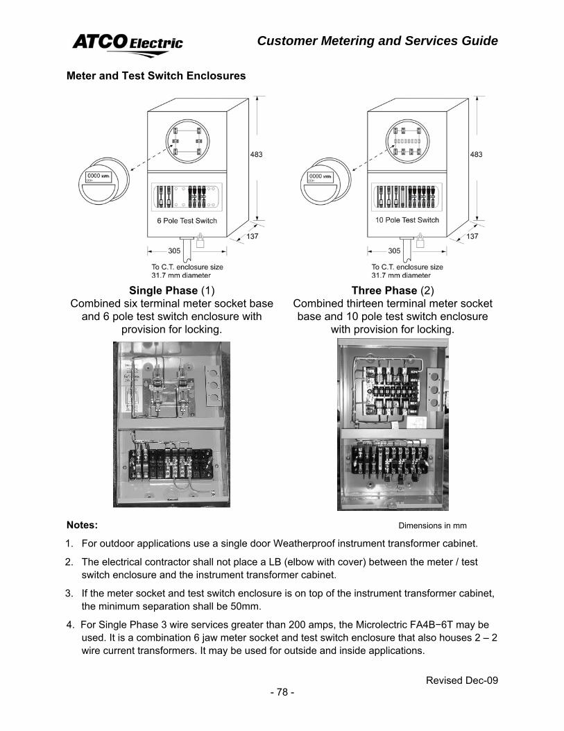
Customer Metering and Services Guide
Revised Dec-09 - 78 -
Meter and Test Switch Enclosures
Single Phase (1)
Combined six terminal meter socket base and 6 pole test switch enclosure with
provision for locking.
Three Phase (2) Combined thirteen terminal meter socket base and 10 pole test switch enclosure
with provision for locking.
Notes: Dimensions in mm
1. For outdoor applications use a single door Weatherproof instrument transformer cabinet.
2. The electrical contractor shall not place a LB (elbow with cover) between the meter / test switch enclosure and the instrument transformer cabinet.
3. If the meter socket and test switch enclosure is on top of the instrument transformer cabinet, the minimum separation shall be 50mm.
4. For Single Phase 3 wire services greater than 200 amps, the Microlectric FA4B−6T may be used. It is a combination 6 jaw meter socket and test switch enclosure that also houses 2 – 2 wire current transformers. It may be used for outside and inside applications.
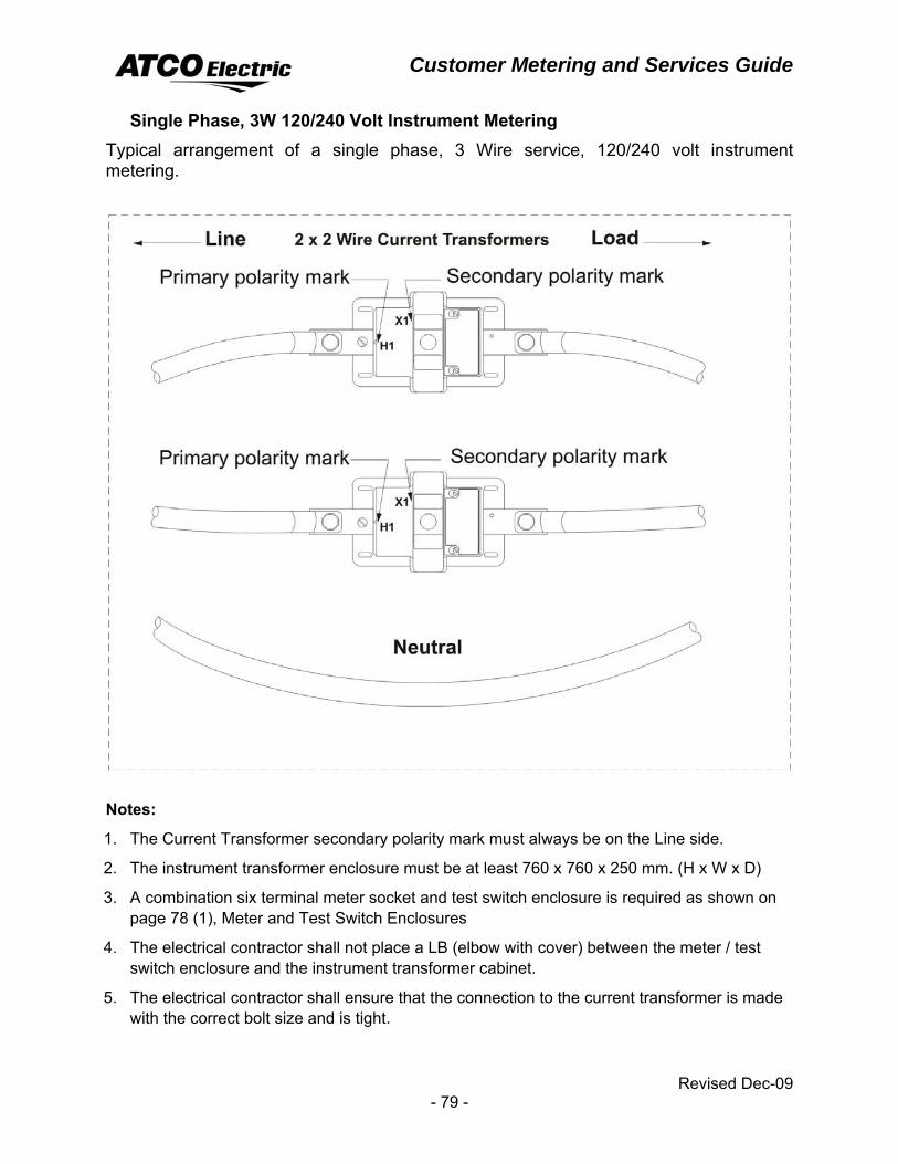
Customer Metering and Services Guide
Revised Dec-09 - 79 -
Single Phase, 3W 120/240 Volt Instrument Metering Typical arrangement of a single phase, 3 Wire service, 120/240 volt instrument metering.
Notes:
1. The Current Transformer secondary polarity mark must always be on the Line side.
2. The instrument transformer enclosure must be at least 760 x 760 x 250 mm. (H x W x D)
3. A combination six terminal meter socket and test switch enclosure is required as shown on page 78 (1), Meter and Test Switch Enclosures
4. The electrical contractor shall not place a LB (elbow with cover) between the meter / test switch enclosure and the instrument transformer cabinet.
5. The electrical contractor shall ensure that the connection to the current transformer is made with the correct bolt size and is tight.
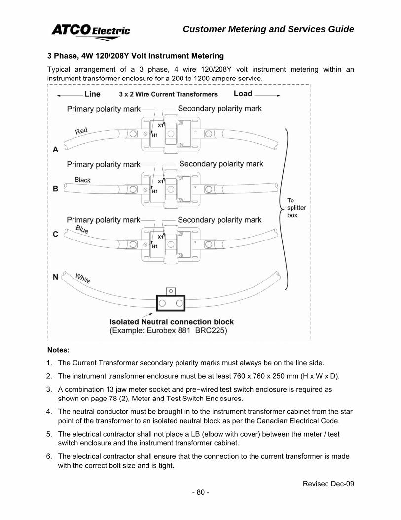
Customer Metering and Services Guide
Revised Dec-09 - 80 -
3 Phase, 4W 120/208Y Volt Instrument Metering Typical arrangement of a 3 phase, 4 wire 120/208Y volt instrument metering within an instrument transformer enclosure for a 200 to 1200 ampere service.
Notes:
1. The Current Transformer secondary polarity marks must always be on the line side.
2. The instrument transformer enclosure must be at least 760 x 760 x 250 mm (H x W x D).
3. A combination 13 jaw meter socket and pre−wired test switch enclosure is required as shown on page 78 (2), Meter and Test Switch Enclosures.
4. The neutral conductor must be brought in to the instrument transformer cabinet from the star point of the transformer to an isolated neutral block as per the Canadian Electrical Code.
5. The electrical contractor shall not place a LB (elbow with cover) between the meter / test switch enclosure and the instrument transformer cabinet.
6. The electrical contractor shall ensure that the connection to the current transformer is made with the correct bolt size and is tight.
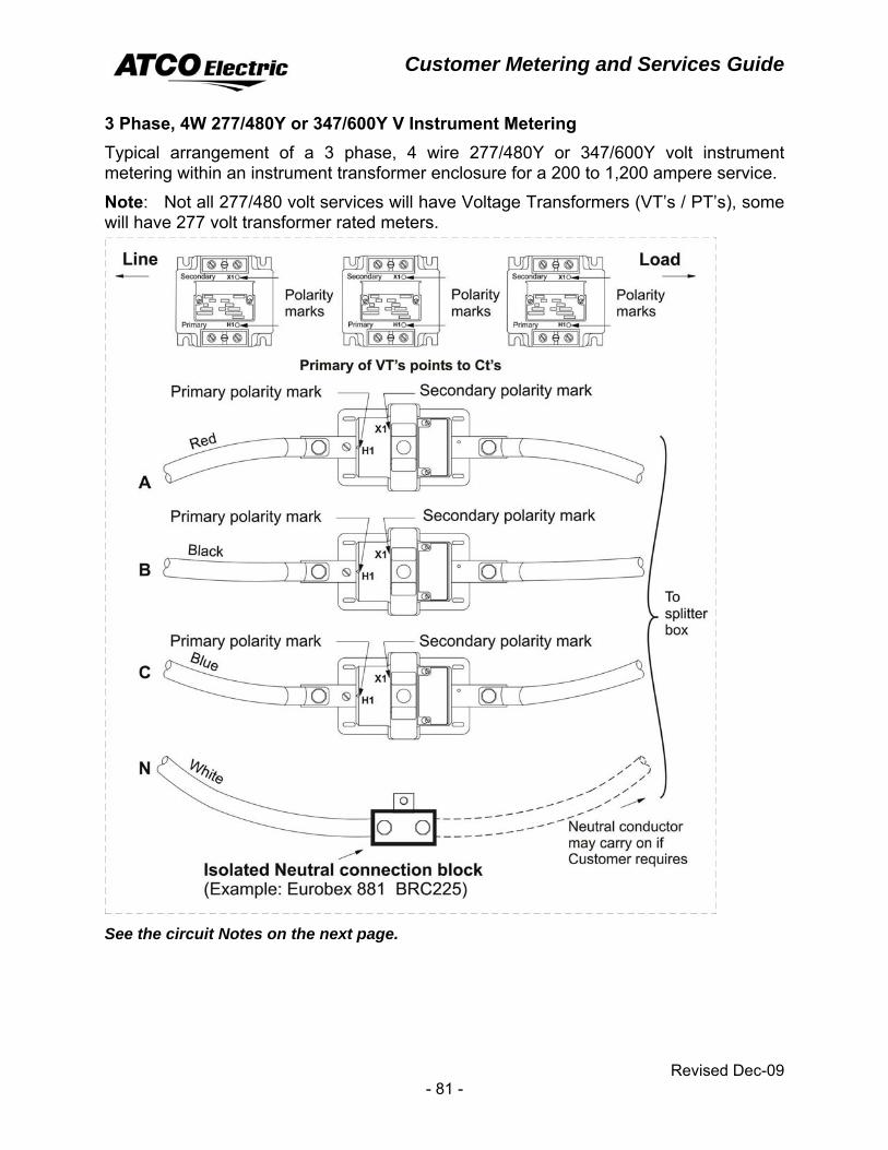
Customer Metering and Services Guide
Revised Dec-09 - 81 -
3 Phase, 4W 277/480Y or 347/600Y V Instrument Metering Typical arrangement of a 3 phase, 4 wire 277/480Y or 347/600Y volt instrument metering within an instrument transformer enclosure for a 200 to 1,200 ampere service.
Note: Not all 277/480 volt services will have Voltage Transformers (VT’s / PT’s), some will have 277 volt transformer rated meters.
See the circuit Notes on the next page.
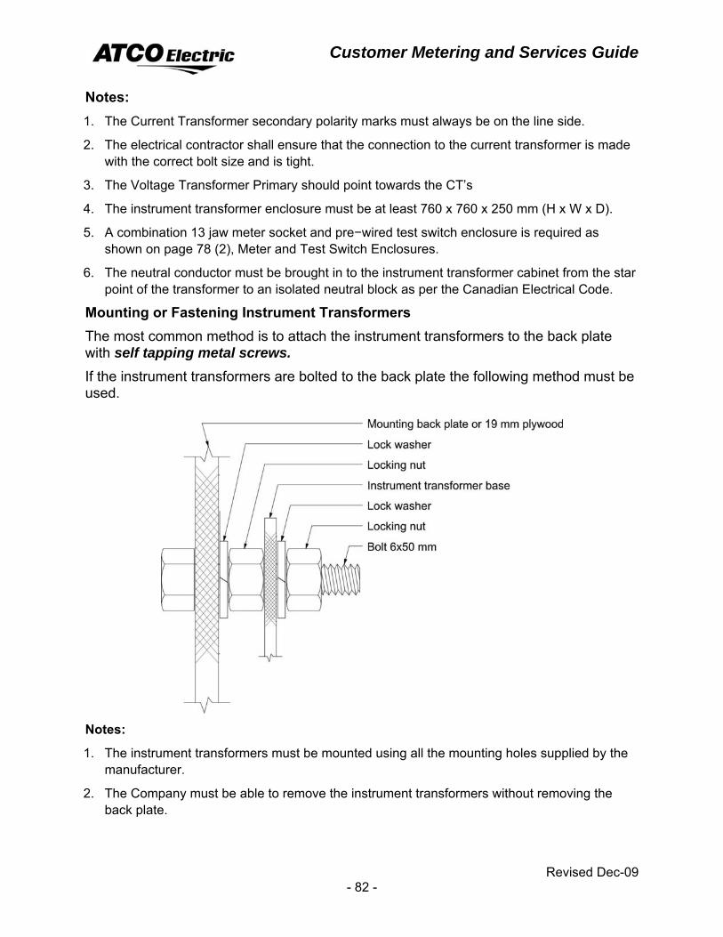
Customer Metering and Services Guide
Revised Dec-09 - 82 -
Notes: 1. The Current Transformer secondary polarity marks must always be on the line side.
2. The electrical contractor shall ensure that the connection to the current transformer is made with the correct bolt size and is tight.
3. The Voltage Transformer Primary should point towards the CT’s
4. The instrument transformer enclosure must be at least 760 x 760 x 250 mm (H x W x D).
5. A combination 13 jaw meter socket and pre−wired test switch enclosure is required as shown on page 78 (2), Meter and Test Switch Enclosures.
6. The neutral conductor must be brought in to the instrument transformer cabinet from the star point of the transformer to an isolated neutral block as per the Canadian Electrical Code.
Mounting or Fastening Instrument Transformers The most common method is to attach the instrument transformers to the back plate with self tapping metal screws. If the instrument transformers are bolted to the back plate the following method must be used.
Notes:
1. The instrument transformers must be mounted using all the mounting holes supplied by the manufacturer.
2. The Company must be able to remove the instrument transformers without removing the back plate.

Customer Metering and Services Guide
Revised Dec-09 - 83 -
3 Phase, 4W 347/600Y V Instrument Metering − AMR Equipped
Notes:
1. ATCO Electric supplies and installs the External 2 kVA signaling transformer for AMR.
2. Space of 450 X 450 mm is required at the instrument transformer cabinet to mount the unit.
3. All wiring of AMR equipment is completed by ATCO Electric.
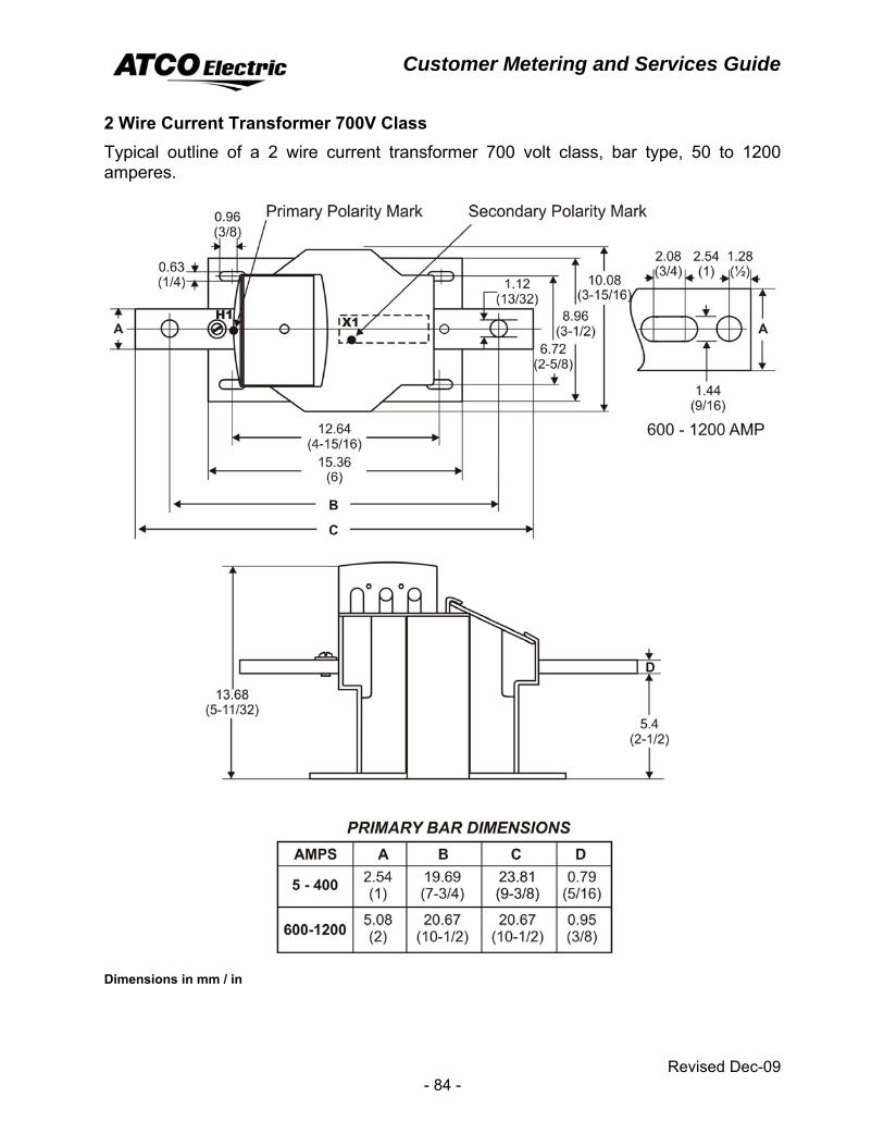
Customer Metering and Services Guide
Revised Dec-09 - 84 -
2 Wire Current Transformer 700V Class Typical outline of a 2 wire current transformer 700 volt class, bar type, 50 to 1200 amperes.
Dimensions in mm / in
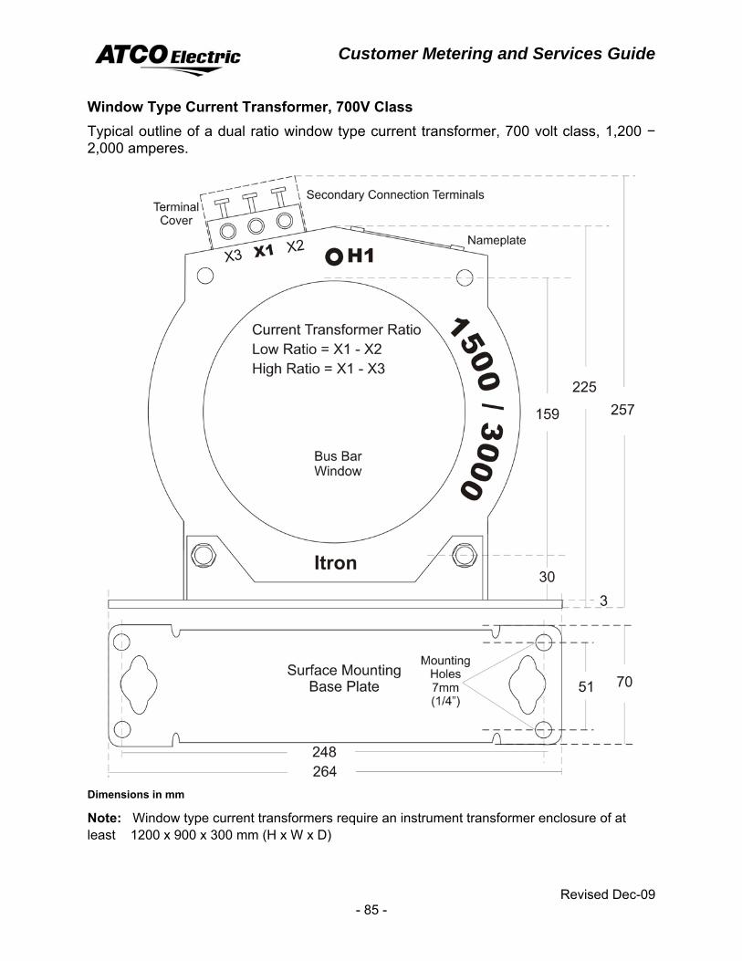
Customer Metering and Services Guide
Revised Dec-09 - 85 -
Window Type Current Transformer, 700V Class Typical outline of a dual ratio window type current transformer, 700 volt class, 1,200 − 2,000 amperes.
Dimensions in mm
Note: Window type current transformers require an instrument transformer enclosure of at least 1200 x 900 x 300 mm (H x W x D)
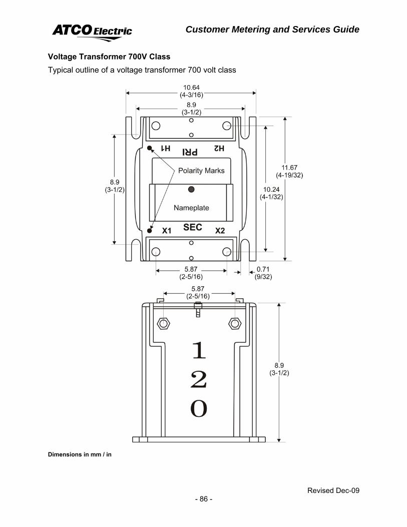
Customer Metering and Services Guide
Revised Dec-09 - 86 -
Voltage Transformer 700V Class Typical outline of a voltage transformer 700 volt class
Dimensions in mm / in
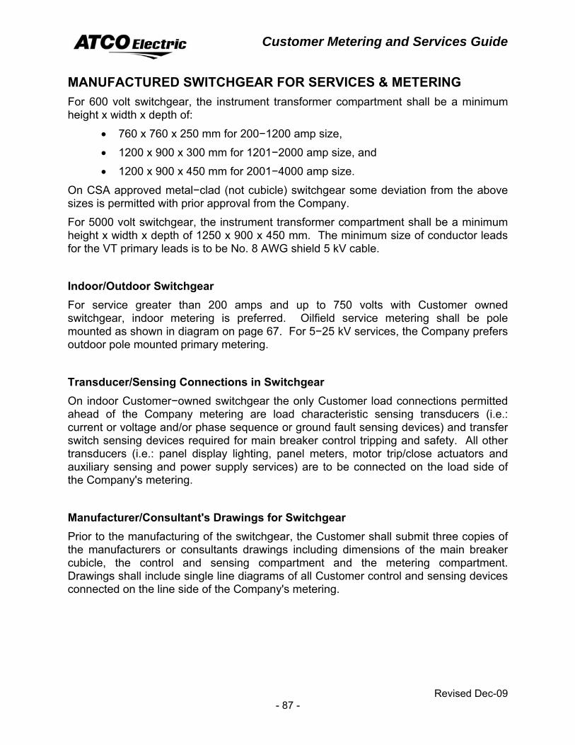
Customer Metering and Services Guide
Revised Dec-09 - 87 -
MANUFACTURED SWITCHGEAR FOR SERVICES & METERING For 600 volt switchgear, the instrument transformer compartment shall be a minimum height x width x depth of:
• 760 x 760 x 250 mm for 200−1200 amp size,
• 1200 x 900 x 300 mm for 1201−2000 amp size, and
• 1200 x 900 x 450 mm for 2001−4000 amp size.
On CSA approved metal−clad (not cubicle) switchgear some deviation from the above sizes is permitted with prior approval from the Company.
For 5000 volt switchgear, the instrument transformer compartment shall be a minimum height x width x depth of 1250 x 900 x 450 mm. The minimum size of conductor leads for the VT primary leads is to be No. 8 AWG shield 5 kV cable.
Indoor/Outdoor Switchgear For service greater than 200 amps and up to 750 volts with Customer owned switchgear, indoor metering is preferred. Oilfield service metering shall be pole mounted as shown in diagram on page 67. For 5−25 kV services, the Company prefers outdoor pole mounted primary metering.
Transducer/Sensing Connections in Switchgear On indoor Customer−owned switchgear the only Customer load connections permitted ahead of the Company metering are load characteristic sensing transducers (i.e.: current or voltage and/or phase sequence or ground fault sensing devices) and transfer switch sensing devices required for main breaker control tripping and safety. All other transducers (i.e.: panel display lighting, panel meters, motor trip/close actuators and auxiliary sensing and power supply services) are to be connected on the load side of the Company's metering.
Manufacturer/Consultant's Drawings for Switchgear Prior to the manufacturing of the switchgear, the Customer shall submit three copies of the manufacturers or consultants drawings including dimensions of the main breaker cubicle, the control and sensing compartment and the metering compartment. Drawings shall include single line diagrams of all Customer control and sensing devices connected on the line side of the Company's metering.
Customer Metering and Services Guide
Revised Dec-09 - 88 -
CT Cabinet and Switchgear Enclosure The CT cabinet of the switchgear shall be at least 100 mm above the floor and the switchgear enclosures height shall be no more that 2400 mm above the floor. The enclosure door(s) shall swing open a minimum of 110 degrees. Two vertically hinged doors are preferred; however a single−hinged door is acceptable. Provisions for locking the door(s) of the CT cabinet must be provided.
Warning Signs for Manufactured Switchgear The Customer shall place a sign warning of live (fused) components, even if the breaker is open in a conspicuous location near the main breaker.
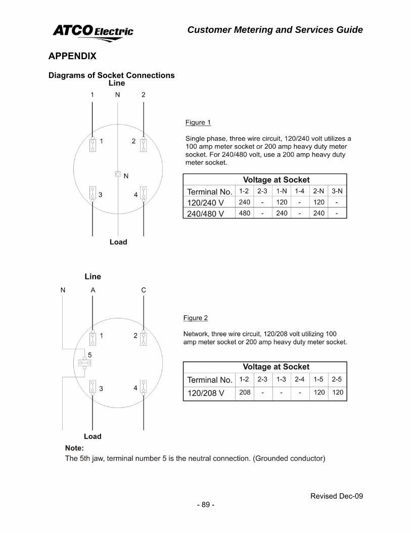
Customer Metering and Services Guide
Revised Dec-09 - 89 -
APPENDIX Diagrams of Socket Connections
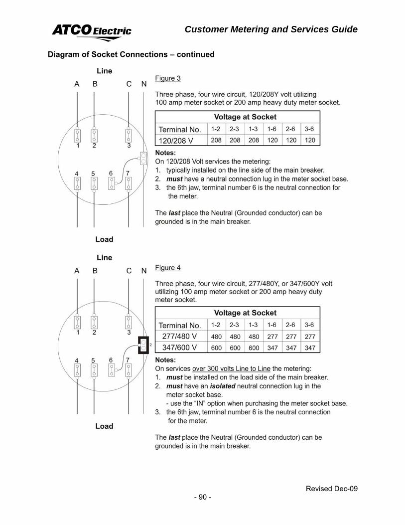
Customer Metering and Services Guide
Revised Dec-09 - 90 -
Diagram of Socket Connections – continued
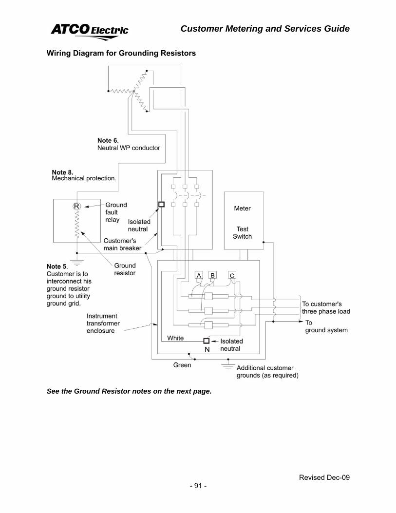
Customer Metering and Services Guide
Revised Dec-09 - 91 -
Wiring Diagram for Grounding Resistors
See the Ground Resistor notes on the next page.
Customer Metering and Services Guide
Revised Dec-09 - 92 -
Notes: 1. Transformer primary; ground the primary star point, transformer case and
interconnect with ground from lightning arresters, if installed. The secondary neutral is grounded through the ground resistor.
2. At the transformer, the Customer's main breaker and the instrument transformer enclosure, install a sign reading "Caution grounding resistor installed. Do not tie secondary neutral to case ground." Obtain the sign from metering services.
3. The design of the ground resistor must be coordinated with ATCO Electric engineering.
4. On star−star transformers, the internally connected primary and secondary grounds must be separated.
5. Where the ground resistor is installed inside a substation, the resistor case ground and the transformer case must be interconnected to the ground.
6. The Customer is to install an insulated bushing for the neutral weather proof (WP) conductor which is allowed to pass through the main breaker. The neutral is only for the star point for the metering.
7. An installation of 5 kV or 25 kV metering on a secondary service is similar to the above and must include a means for disconnecting the service on the supply side of the metering set.
8. The conductor from the X0 transformer bushing to the ground resistor must be encased in PVC conduit and the lead from the ground resistor to the Customer's building must be mechanically protected from damage with conduit, unless protected by elevation above ground.
9. Refer to Canadian Electrical Code − Part 1, 10−1100 to 10−1108 for conductor sizing and installation of neutral grounding devices.
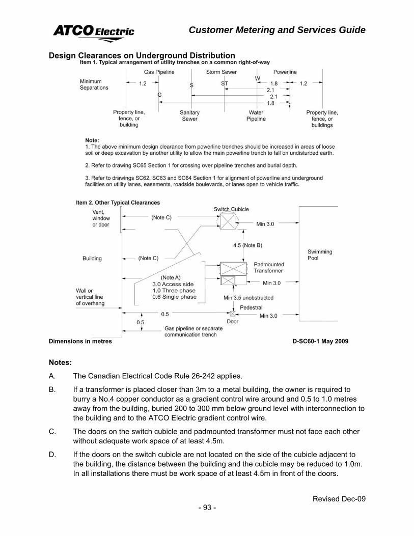
Customer Metering and Services Guide
Revised Dec-09 - 93 -
Design Clearances on Underground Distribution
Dimensions in metres D-SC60-1 May 2009
Notes:
A. The Canadian Electrical Code Rule 26-242 applies.
B. If a transformer is placed closer than 3m to a metal building, the owner is required to burry a No.4 copper conductor as a gradient control wire around and 0.5 to 1.0 metres away from the building, buried 200 to 300 mm below ground level with interconnection to the building and to the ATCO Electric gradient control wire.
C. The doors on the switch cubicle and padmounted transformer must not face each other without adequate work space of at least 4.5m.
D. If the doors on the switch cubicle are not located on the side of the cubicle adjacent to the building, the distance between the building and the cubicle may be reduced to 1.0m. In all installations there must be work space of at least 4.5m in front of the doors.
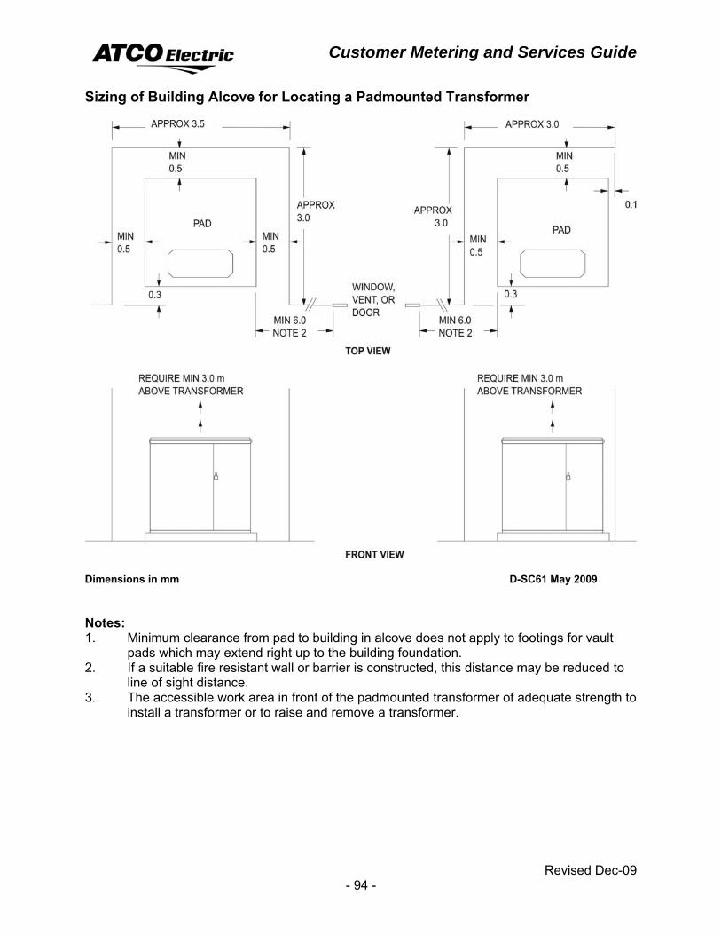
Customer Metering and Services Guide
Revised Dec-09 - 94 -
Sizing of Building Alcove for Locating a Padmounted Transformer
Dimensions in mm D-SC61 May 2009 Notes: 1. Minimum clearance from pad to building in alcove does not apply to footings for vault
pads which may extend right up to the building foundation. 2. If a suitable fire resistant wall or barrier is constructed, this distance may be reduced to
line of sight distance. 3. The accessible work area in front of the padmounted transformer of adequate strength to
install a transformer or to raise and remove a transformer.
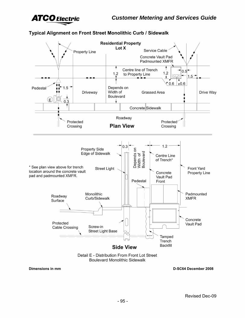
Customer Metering and Services Guide
Revised Dec-09 - 95 -
Typical Alignment on Front Street Monolithic Curb / Sidewalk
Dimensions in mm D-SC64 December 2008
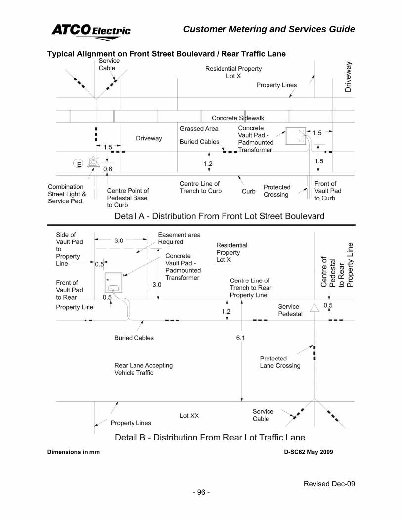
Customer Metering and Services Guide
Revised Dec-09 - 96 -
Typical Alignment on Front Street Boulevard / Rear Traffic Lane
Dimensions in mm D-SC62 May 2009
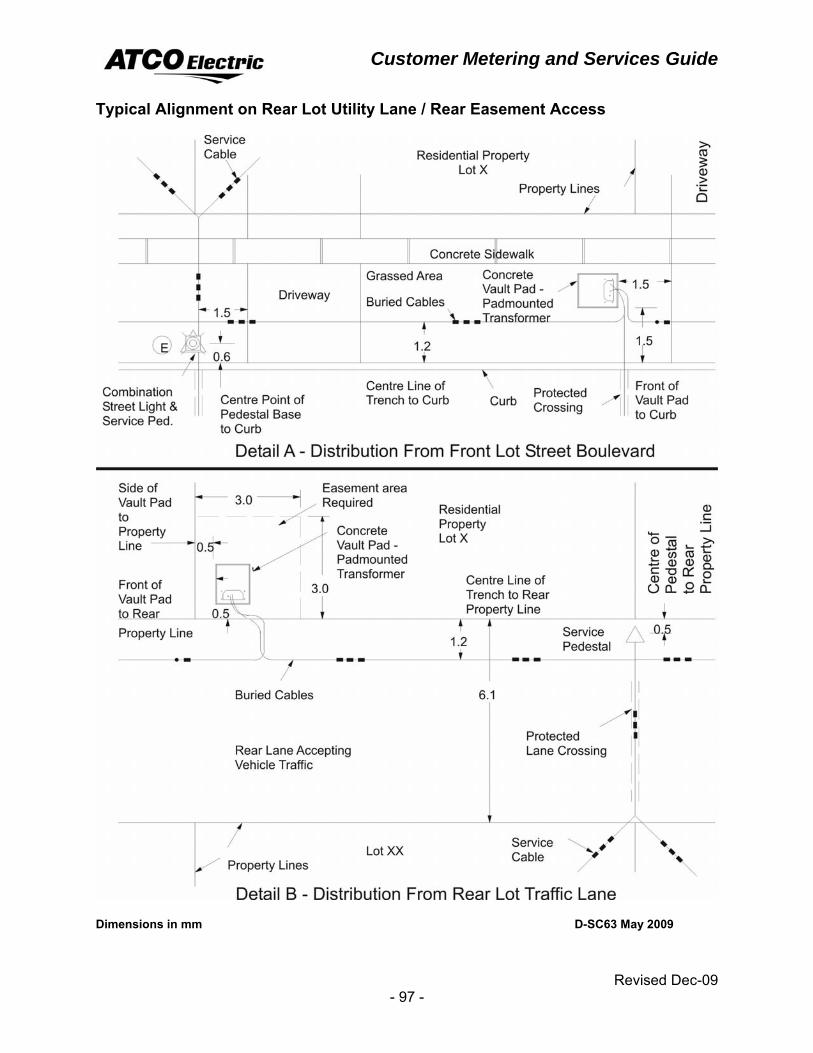
Customer Metering and Services Guide
Revised Dec-09 - 97 -
Typical Alignment on Rear Lot Utility Lane / Rear Easement Access
Dimensions in mm D-SC63 May 2009

Customer Metering and Services Guide
Revised Dec-09 - 98 -
Landscaping Adjacent to Underground Electrical Equipment
D-H25-1 May 2009
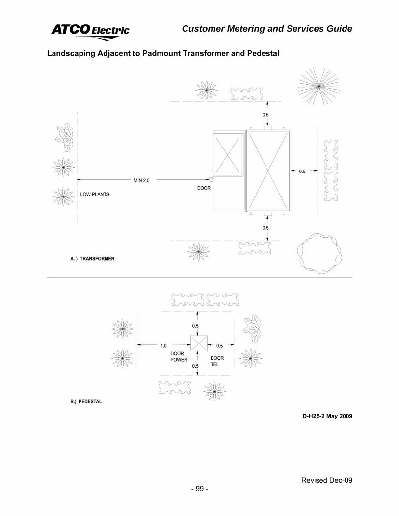
Customer Metering and Services Guide
Revised Dec-09 - 99 -
Landscaping Adjacent to Padmount Transformer and Pedestal
D-H25-2 May 2009
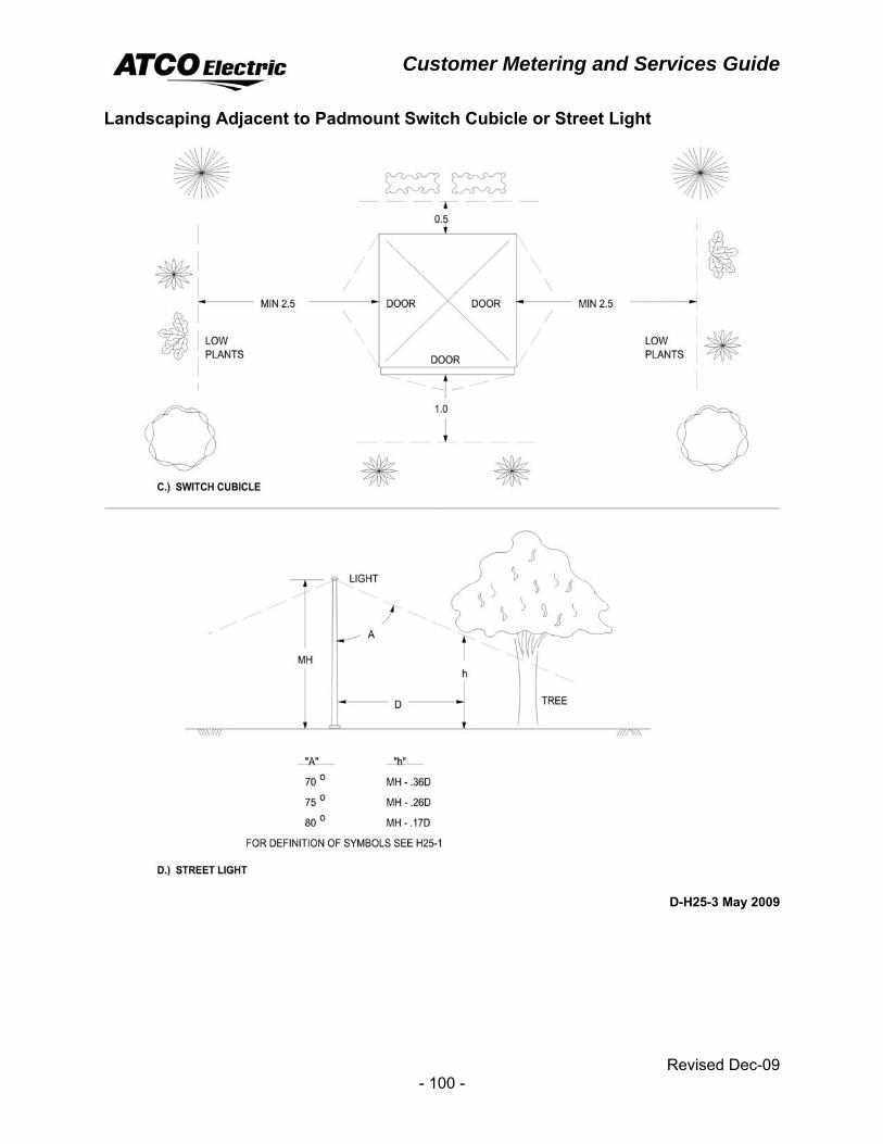
Customer Metering and Services Guide
Revised Dec-09 - 100 -
Landscaping Adjacent to Padmount Switch Cubicle or Street Light
D-H25-3 May 2009
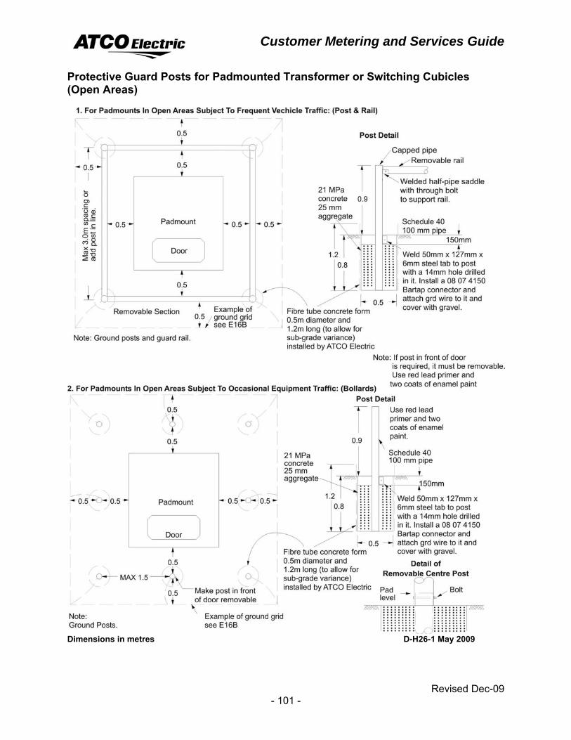
Customer Metering and Services Guide
Revised Dec-09 - 101 -
Protective Guard Posts for Padmounted Transformer or Switching Cubicles (Open Areas)
Dimensions in metres D-H26-1 May 2009
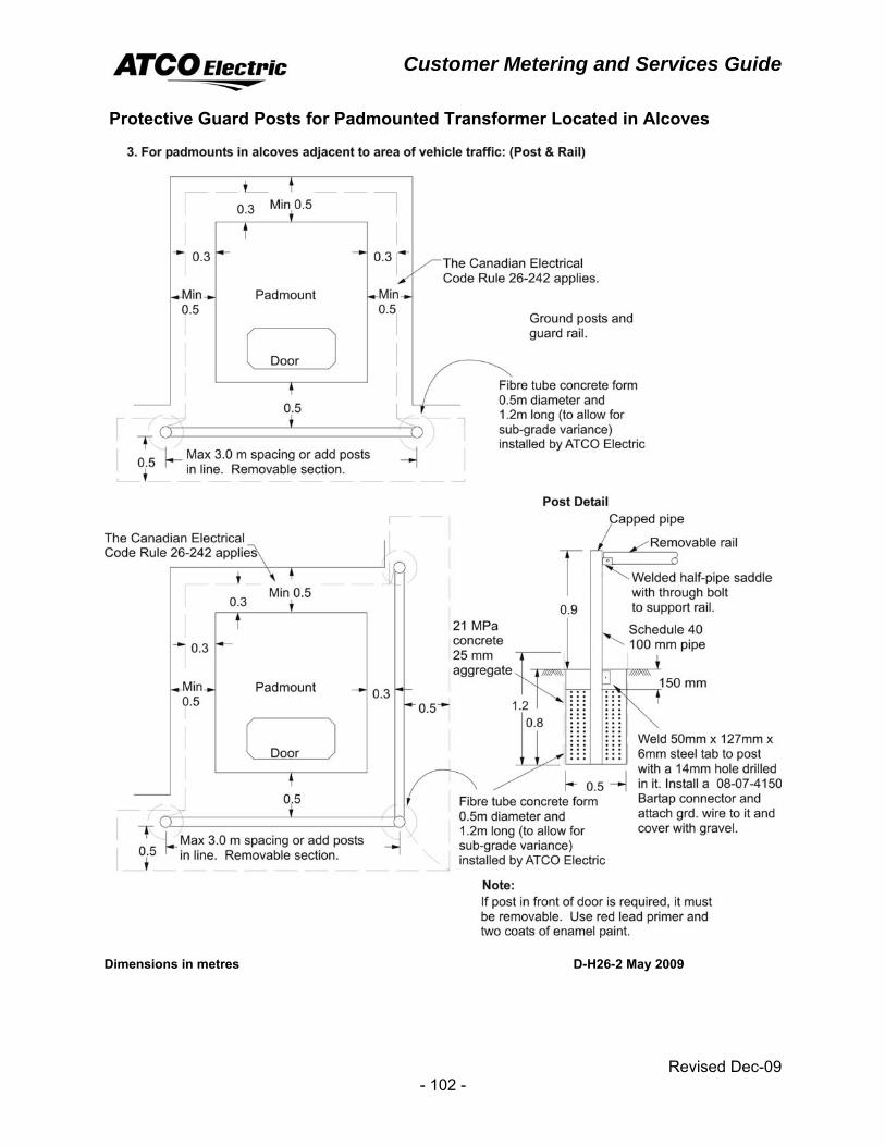
Customer Metering and Services Guide
Revised Dec-09 - 102 -
Protective Guard Posts for Padmounted Transformer Located in Alcoves
Dimensions in metres D-H26-2 May 2009