Embed Size (px)
Citation preview
LOW NOISE AMPLIFIER DESIGN FOR RADIO TELESCOPE SYSTEM
VAHID KOUHDARAGH
UNIVERSITI TEKNOLOGI MALAYSIA
UNIVERSITY TECHNOLOGY OF MALAYSIA
LOW NOISE AMPLIFIER DESIGN FOR RADIO TELESCOPE SYSTEM
VAHID KOUHDARAGH
A project report submitted in partial fulfillment of the
requirements for the award of the degree of
Master of Science (Electronic and Telecommunication Engineering)
Faculty of Electrical
University Technology of Malaysia
NOVEMBER 2009
iii
Dedicated to my beloved family and country, Iran.
iv
ACKNOWLEDGEMENT
First and foremost, I would like to express my gratitude to God for His
abundant grace that I am able to be what I am today. I also wish to express my
sincere appreciation to my thesis supervisor, Dr. Sharifah Kamilah Bte Syed Yusof
for her precious guidance, encouragement, critics, advices, knowledge and
motivation. Without her support and interest, this thesis would not have been the
same as presented here.
I would love to express my thank you to all my fellow postgraduate students
who have been going through the thick and thins during the development of this
thesis. My sincere appreciation also goes to all my colleagues and friends who have
provided assistance at various occasions. Last but not least, a very special
appreciation goes to my family for their continuous supports, loves and cares.
v
ABSTRACT
The purpose of this project is to design a low noise amplifier (LNA) for a
radio telescope. The LNA is an electronic amplifier used in communication systems
to amplify extremely weak signals captured by antennae. This thesis describes the
procedure of designing an LNA for 7 GHz frequency. Noise matching is an
important technique which was considered in the design process. The designed LNA
achieved a gain of 30 dB with 1 GHz bandwidth. The noise figure achieved was less
than 2.9 dB. Return-losses were improved by 6 dB with a new proposed optimization
method.
ABSTRAK
Objektif projek ini adalah untuk mencipta sebuah penguat suara rendah
(LNA) untuk teleskop radio. The LNA adalah penguat elektronik yang digunakan
dalam sistem komunikasi untuk menguatkan isyarat yang sangat lemah untuk
ditangkap oleh antena. Tesis ini menjelaskan seluruh prosedur dalam penciptaan
sebuah LNA selama 7 GHz frekuensi. Kebisingan yang berpadanan adalah teknik
penting yang dipertimbangkan dalam proses penciptaan. LNA yang dicipta dapat
mencapai gain 30 dB dengan 1 GHz bandwidth. Angka hingar yang diperolehi
adalah kurang daripada 2,9 dB. Kehilangan dapat diperbaiki sebanyak 6 dB dengan
kaedah yang dicadangkan.
viii
TABLE OF CONTENT
CHAPTER TITLE PAGE
TITLE i
DECLARATION ii
DEDICATION iii
ACKNOWLEDGEMENTS iv
ABSTRACT v
TABLE OF CONTENT vi
LIST OF APPENDICES vii
LIST OF TABLES xii
LIST OF FIGURES xiii
LIST OF ABBREVIATIONS xvi
LIST OF SYMBOLSLS / NOTAITIONS xvii
1 INTRODUCTION 1
1.1 Radio Telescope 1
1.2 LNA‟s Usage in Radio Telescope 2
1.3 Noise and Temperature 3
1.4 FET Modeling and Noise Parameter 4
ix
1.5 Reducing Receiver Front-End Noise 5
1.6 Problem Statement 6
1.7 Project Objectives 6
1.8 Scope of Study 7
2 LITERATURE REVIEW 8
2.1 LNA in Radio Telescope 9
2.2 The Ideal Amplifier and LNA 9
2.3 Investigation on Previous Studies 13
2.3.1 Dual MOSFET in LNA Design 13
2.3.2 2-Stage LNA by MOSFET 15
2.3.3 LNA Design with Chebyshev Filter 16
3 METHODOLOGY 20
3.1 Introduction 20
3.2 Noise, Noise Temperature and Noise Figure 23
3.3 Designing Process 24
3.4 Calculations and Designing Process 24
3.4.1 Biasing 24
3.4.2 Design Rules for Impedance Matching Networks 26
3.4.3 Design of Impedance Matching Networks 27
3.4.3.1 Input Matching Network for 7 GHz 27
3.4.3.2 Output Matching for 7 GHz 29
3.4.3.3 Intermediate Matching Network for 7 GHz 31
3.4.4 Improving Return Losses 32
3.5 Stability at 7 GHz for ATF-34143 33
3.6 Schematic of Circuit at Two Stages and component
Values 35
x
3.7 Designing for 5 Stage 37
3.8 New Method for Improving Return Losses 38
4 RESAULTs AND ANALYZING 41
4.1 Introduction 41
4.2 2-Stage Cascade LNA 41
4.3 5-Stage LNA 47
4.4 Previous Studies Analyzing 52
4.5 Conclusion 57
5 CONCLUSION AND DISCUSSION 58
REFERENCES 59
APPENDICES A-B 65-84
xi
LIST OF APPENDICES
APPENDIX TITLE PAGE
A Process Flow Chart 65
B Gantt Chart Project 2 67
C Data Sheet 69
xii
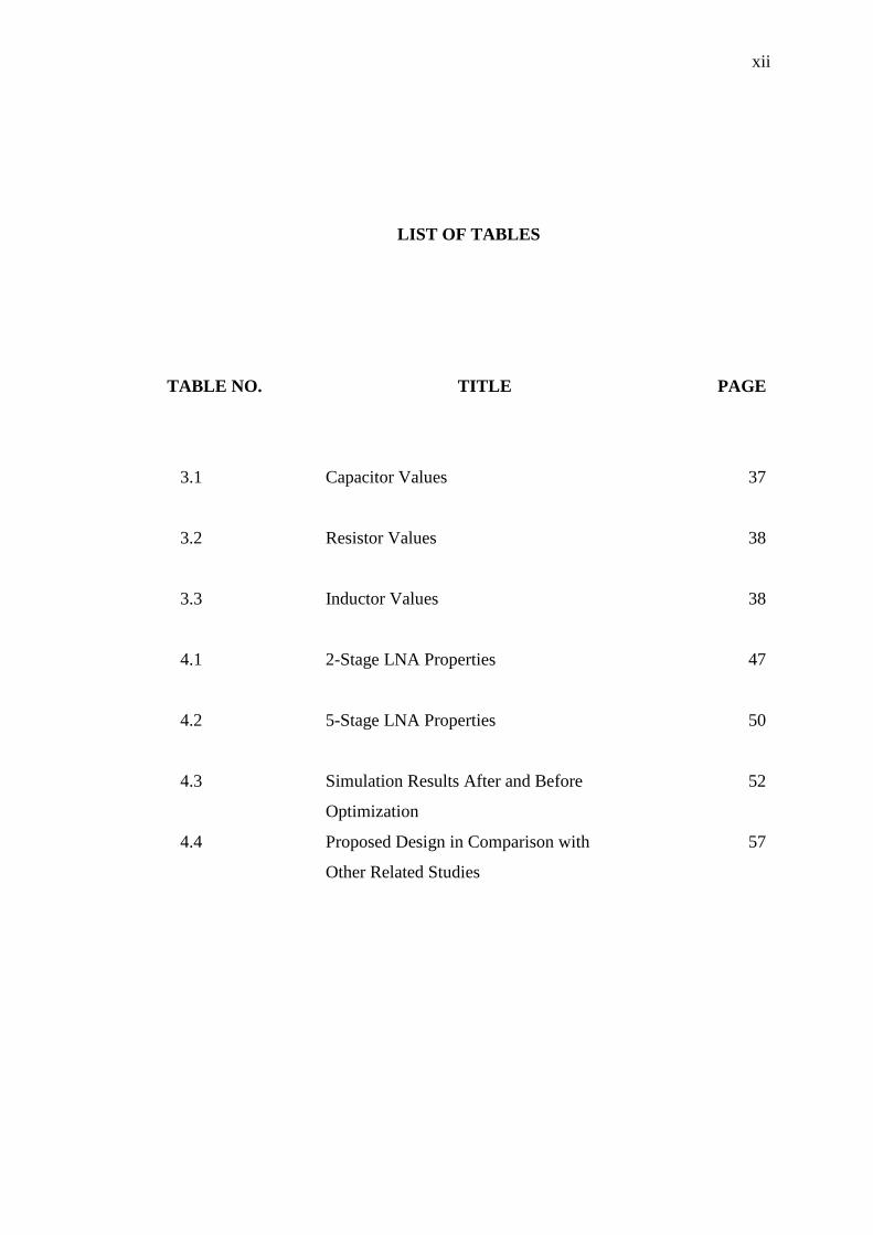
LIST OF TABLES
TABLE NO. TITLE PAGE
3.1 Capacitor Values 37
3.2 Resistor Values 38
3.3 Inductor Values 38
4.1 2-Stage LNA Properties 47
4.2 5-Stage LNA Properties 50
4.3 Simulation Results After and Before 52
Optimization
4.4 Proposed Design in Comparison with 57
Other Related Studies
xiii
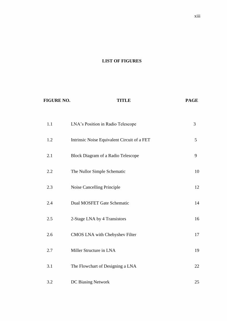
LIST OF FIGURES
FIGURE NO. TITLE PAGE
1.1 LNA‟s Position in Radio Telescope 3
1.2 Intrinsic Noise Equivalent Circuit of a FET 5
2.1 Block Diagram of a Radio Telescope 9
2.2 The Nullor Simple Schematic 10
2.3 Noise Cancelling Principle 12
2.4 Dual MOSFET Gate Schematic 14
2.5 2-Stage LNA by 4 Transistors 16
2.6 CMOS LNA with Chebyshev Filter 17
2.7 Miller Structure in LNA 19
3.1 The Flowchart of Designing a LNA 22
3.2 DC Biasing Network 25
xiv
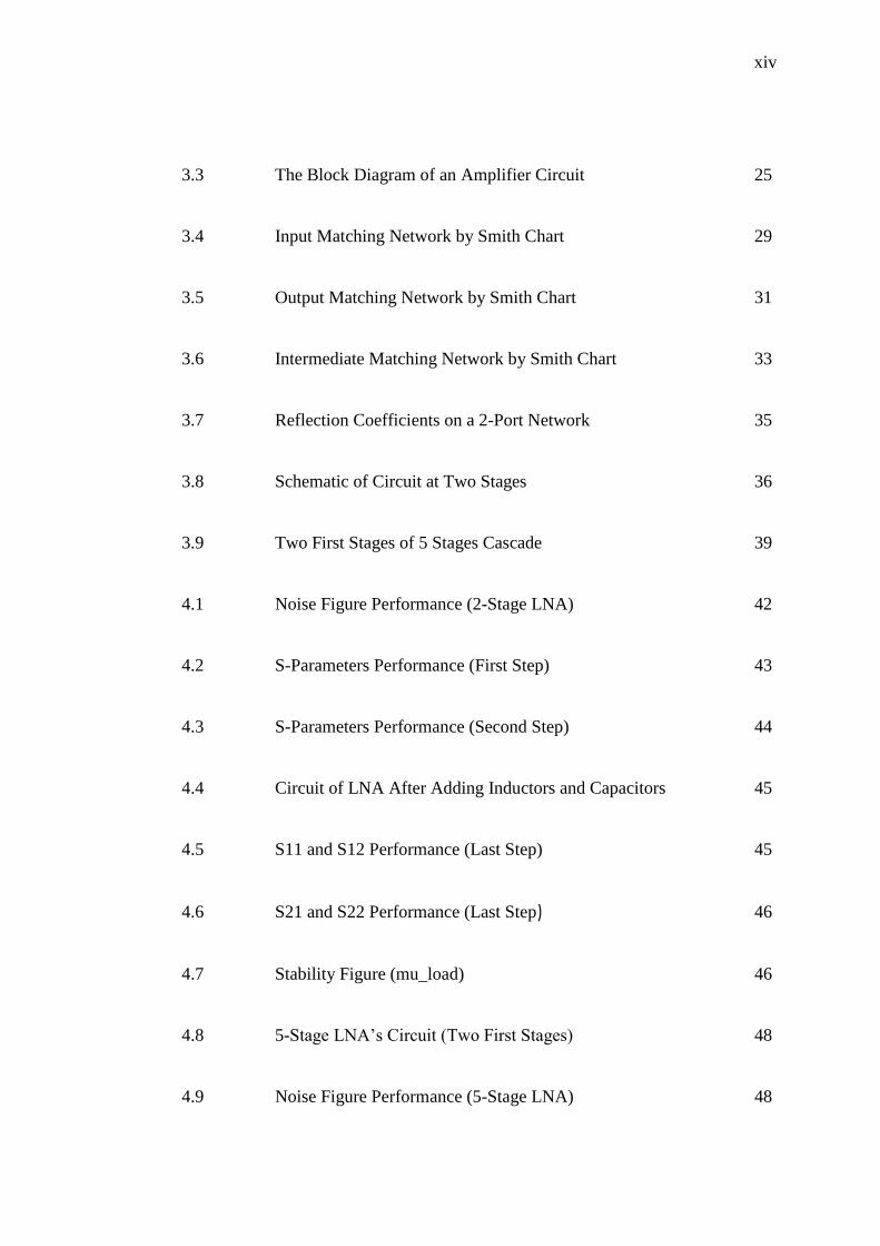
3.3 The Block Diagram of an Amplifier Circuit 25
3.4 Input Matching Network by Smith Chart 29
3.5 Output Matching Network by Smith Chart 31
3.6 Intermediate Matching Network by Smith Chart 33
3.7 Reflection Coefficients on a 2-Port Network 35
3.8 Schematic of Circuit at Two Stages 36
3.9 Two First Stages of 5 Stages Cascade 39
4.1 Noise Figure Performance (2-Stage LNA) 42
4.2 S-Parameters Performance (First Step) 43
4.3 S-Parameters Performance (Second Step) 44
4.4 Circuit of LNA After Adding Inductors and Capacitors 45
4.5 S11 and S12 Performance (Last Step) 45
4.6 S21 and S22 Performance (Last Step) 46
4.7 Stability Figure (mu_load) 46
4.8 5-Stage LNA‟s Circuit (Two First Stages) 48
4.9 Noise Figure Performance (5-Stage LNA) 48
xv
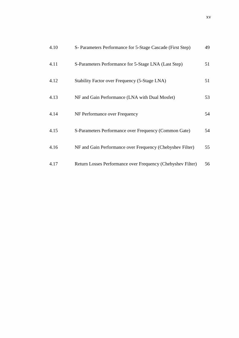
4.10 S- Parameters Performance for 5-Stage Cascade (First Step) 49
4.11 S-Parameters Performance for 5-Stage LNA (Last Step) 51
4.12 Stability Factor over Frequency (5-Stage LNA) 51
4.13 NF and Gain Performance (LNA with Dual Mosfet) 53
4.14 NF Performance over Frequency 54
4.15 S-Parameters Performance over Frequency (Common Gate) 54
4.16 NF and Gain Performance over Frequency (Chebyshev Filter) 55
4.17 Return Losses Performance over Frequency (Chebyshev Filter) 56
xvi
LIST OF ABBREVIATIONS
LNA - Low Noise Amplifier
ADS - Advance Design System
NF - Noise Figure
xvii
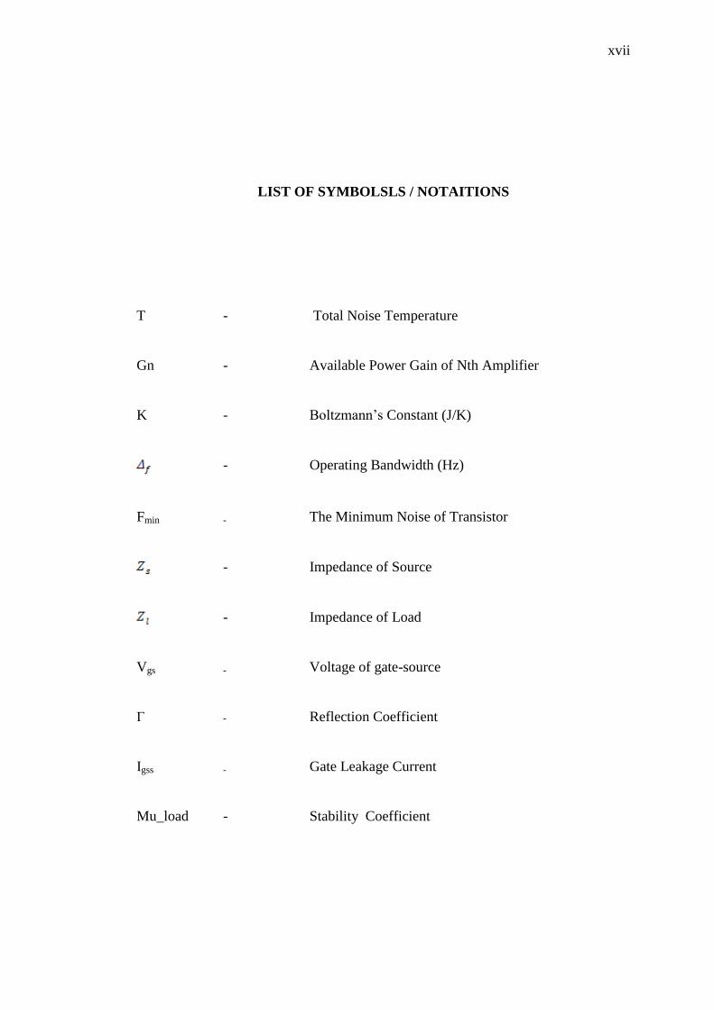
LIST OF SYMBOLSLS / NOTAITIONS
T - Total Noise Temperature
Gn - Available Power Gain of Nth Amplifier
K - Boltzmann‟s Constant (J/K)
- Operating Bandwidth (Hz)
Fmin - The Minimum Noise of Transistor
- Impedance of Source
- Impedance of Load
Vgs - Voltage of gate-source
Γ - Reflection Coefficient
Igss - Gate Leakage Current
Mu_load - Stability Coefficient
1
CHAPTER 1
INTRODUCTION
1.1 Radio Telescope
A radio telescope is a form of directional radio antenna which is used in radio
astronomy. Radio waves reaching the ground can show objects or phenomena that
are difficult or impossible to detect in other wavelength ranges. Radio telescope
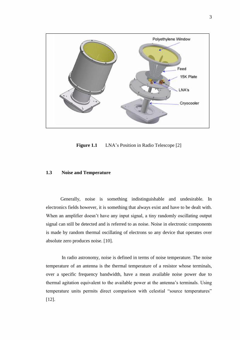
system involves the reflector, sub reflector, tertiary reflector, feed, cryogenics
subsystem, LNA, noise calibration system, frequency converters, digital
spectrometers, continuum signal processing, and monitor and control system. In this
thesis, the focus of the work would be on Low Noise Amplifier (LNA) design for
radio telescope system. [2]
1.2 LNA’s Usage in Radio Telescope
The LNA is a particular type of electronic amplifier which can be used in
communication systems and radio telescopes to amplify very weak signals which is
2
captured by an antenna. In order to reduce the losses in the feed line, the LNA should
be located near to the antenna [1]. The ability of the receiver to detect a weak input
signal is fundamentally limited by the electrical noise which is present at its input.
Therefore proper design techniques should be considered to achieve the lowest
possible noise. LNAs are used in many systems where low-level signals must be
sensed and amplified [22]. Generally, the LNA is capable of decreasing most of the
incoming noise and amplifying a desired signal in a certain frequency range to
increase the signal to noise ratio (SNR) of the communication system and improve
the quality of received signal as well.
LNA‟s are used in conjunction with many radio frequency functions. The
signals which are coming from cosmic sources are originally unprocessed
information and should be analyzed in a proper manner. One of the most critical
building blocks in a radio telescope is LNA. This is because the incident signals from
cosmic sources are very weak in amplitude. Therefore, in order to analyze them they
should be amplified more than other signals [12].
3
Figure 1.1 LNA‟s Position in Radio Telescope [2]
1.3 Noise and Temperature
Generally, noise is something indistinguishable and undesirable. In
electronics fields however, it is something that always exist and have to be dealt with.
When an amplifier doesn‟t have any input signal, a tiny randomly oscillating output
signal can still be detected and is referred to as noise. Noise in electronic components
is made by random thermal oscillating of electrons so any device that operates over
absolute zero produces noise. [10].
In radio astronomy, noise is defined in terms of noise temperature. The noise
temperature of an antenna is the thermal temperature of a resistor whose terminals,
over a specific frequency bandwidth, have a mean available noise power due to
thermal agitation equivalent to the available power at the antenna‟s terminals. Using
temperature units permits direct comparison with celestial “source temperatures”
[12].
4
Every object will produce electromagnetic waves if its temperature is above
absolute zero. The noise temperature of an antenna‟s radiation resistance will be
equal to the temperature of the particular source the antenna is “looking at” if the
angular extent of the source “fills” the antenna beam. This statement excludes non-
thermal mechanisms that generate electromagnetic waves such as synchrotron
radiation. In such cases, the noise temperature of the antenna‟s radiation resistance is
not equal to the thermal temperature of the source but instead would be equivalent to
the thermal temperature of an ideal blackbody emitting the same radiation at the
observing frequency. An ideal blackbody is defined as a perfect absorber and
radiator: it absorbs radiation at all frequencies and its own radiation is a function of
only temperature and frequency [12].
1.4 FET Modeling and Noise Parameter
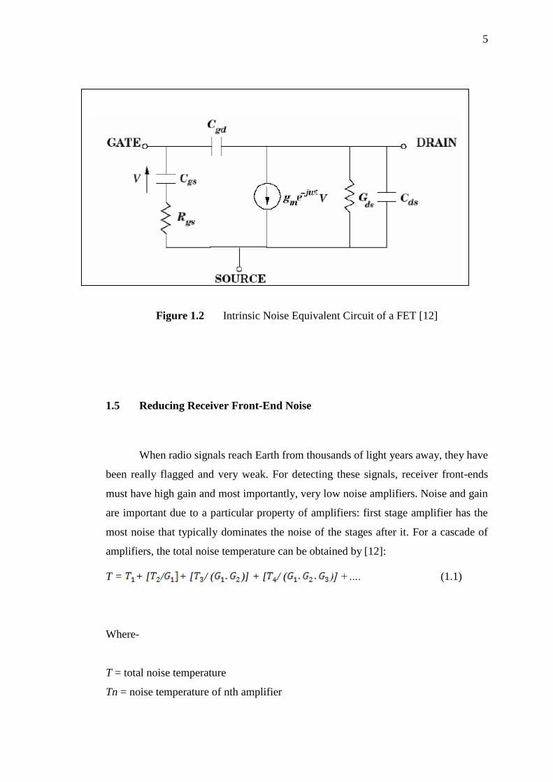
The noise parameters of a FET can be calculated upon obtaining its
equivalent circuit noise model. Theoretically, the noise parameters depend on certain
parameters of the circuit model. The circuit model of the transistor is obtained by
iteratively fitting the model S-parameters to the actual measured S-parameters of the
device. There are various methods of doing this. Here, the chosen method is centered
on least-squares fitting of the simulated output of a circuit model to measured S-
parameters. After convergence, reliable values for various circuit elements such as
package capacitances and inductances are obtained. This method had been used for
manual calculation to obtain the value of NF and it is obvious that by using
sophisticated and strong software there is no worry about complicated calculations
[12]. Figure 1.2 shows intrinsic noise equivalent circuit of a FET.
5
Figure 1.2 Intrinsic Noise Equivalent Circuit of a FET [12]
1.5 Reducing Receiver Front-End Noise
When radio signals reach Earth from thousands of light years away, they have
been really flagged and very weak. For detecting these signals, receiver front-ends
must have high gain and most importantly, very low noise amplifiers. Noise and gain
are important due to a particular property of amplifiers: first stage amplifier has the
most noise that typically dominates the noise of the stages after it. For a cascade of
amplifiers, the total noise temperature can be obtained by [12]:
T = + [ / + [ / ( )] + [ / ( )] +…. (1.1)
Where-
T = total noise temperature
Tn = noise temperature of nth amplifier
6
Gn = available power gain of nth amplifier .
The solution to achieve low noise in an amplifier depends on the type of
transistor being used in the design. Gallium arsenide field-effect transistors (GaAs
FETs) and high electron mobility transistors (HEMTs) are the most familiar types of
transistors that have been used in LNAs for high frequencies. Technology has made
it probable for high frequency amplifiers to have excellent noise performance
without using cryogenic cooling. Although cryogenic cooling of receivers is usually
used to obtain low system noise temperatures in radio astronomy but the high cost of
procedure and maintenance are two main disadvantages of using cryogenic cooling.
Therefore, the application of cryogenic cooling is not considered in this work. There
are several limitations in the design of LNAs for high frequency applications. For
instance, a design for lowest noise may not lead to attain lowest return losses.
Therefore an optimized design is necessary to achieve the lowest noise and return
losses [12].
1.6 Problem Statement
Radio astronomy signals are very weak in amplitude. Therefore, in order to
analyze these signals an amplification of the signal is essential while the noise is
minimized. In order to solve this problem, LNA should be used in radio telescope
receivers. There are several limitations in design of LNAs for high frequency
application, for instance a design for lowest noise may not lead to attain lowest return
losses. Therefore an optimized design is necessary to achieve the lowest noise and
return losses [12].
7
1.7 Project Objectives
The objective of this project is to design a LNA for radio telescope with high
gain and stability and low return losses and noise figure.
1.8 Scope of Study
This study is limited to the following scope of work in order to meet the specified
objectives:
(a) The LNA has been designed for 7 GHz frequency.
(b) LNA should have a gain more than 20 dB.
(c) NF should be less than 3.5 dB.
(d) The input and output return losses should be less than -10 dB.
(e) LNA should be unconditionally stable therefore the K factor should be more
than 1.
(f) The ADS has been used to simulate the circuit and to investigate the stability,
noise figure, gain and return losses.