Embed Size (px)
Citation preview
Customer Information.Installation And Servicing Manual
Condensing Oil Fired Floor standingBoilers.
Models covered by this manual:
Internal Combination 15-41 kw
Internal Mega Combination 41-68 kwInternalSealedSystem 15-41 kw
Kitchen/Utility 15-68 kwOutdoor Combination 15-41 kw
OutdoorMegaCombination 41-68 kwOutdoor Sealed System 15-41 kwOutdoor Standard 15-68 kwBoiler House 15-68 kwNon Condensing Range 15-68 kw
Please Leave These Instructions with the User
ISSUE01-03-2010
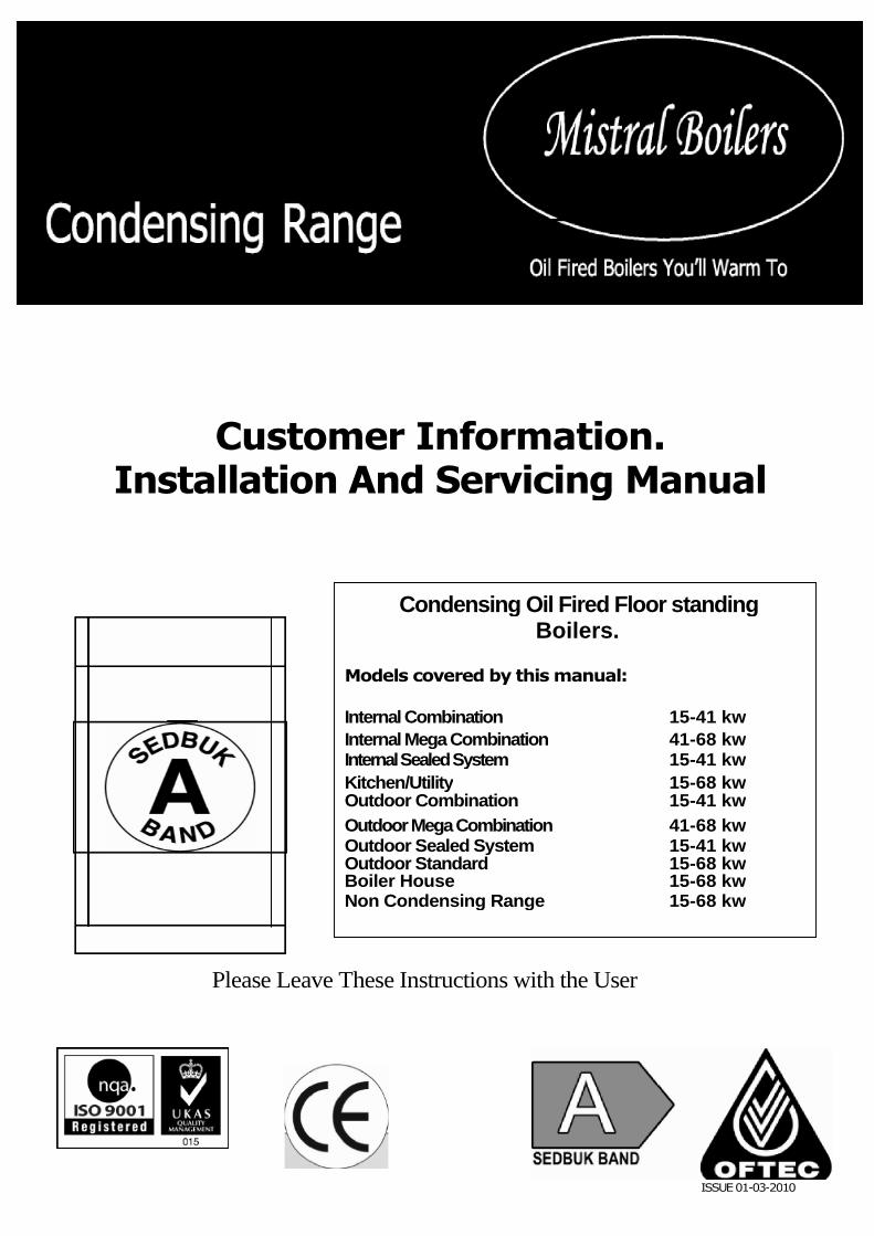
INNER Y SECTION COMBI
Mistral manufacture a comprehensive range of Sedbuk A rated high efficiency oil boilers for domesticand industrial heating applications. Culminating from years of experience, ongoing development andour wealth of technical knowledge the specially developed Mistral ‘Y’ section heat exchangers arefitted to all Mistral condensing and non condensing boilers providing much improved performance andoperating efficiency.
The unique ‘Y’ section centrally located waterway design allows excellent heat transfer to take place,particularly in the lower combustion chamber. This greatly reduces the pressure build up normallyassociated with conventionally manufactured boiler types. The ‘Y’ section design allows baffles to bea more open tolerance, providing for better overall running performance, smoother start ups andcleaner combustion. Baffles fitted to non central waterway heat exchangers, normally have to beextremely tight to attain required efficiencies, which can cause pressure build up and increase sootdeposit in the boiler.
The additional surface heat transfer area created within the boiler by the ‘Y’ section heat exchangeralso allows Mistral to manufacture high KW output boilers within typical domestic appliance sizeenclosures. Mistral Boilers Limited is committed to offering the most technically advanced andextensive range of domestic oil fired boilers available.
WARRANTY
Heat Exchanger – 5 YearsBurner & Controls – 2 Years(Terms & Conditions apply)
SAFETY
Please note that the products are extremely heavy and great care should be taken when moving theappliance around. Specialist equipment should be used where possible, a full risk assessment and aplan of action should be undertaken, prior to purchase to avoid any injury.
INDEX / PAGE CONTENTS
1.0 Health and safety1.1 COSHH ...............................................................................................................................4
1.2 In The Event of a Spillage ....................................................................................................... 41.3 Operation
2.0 User Information
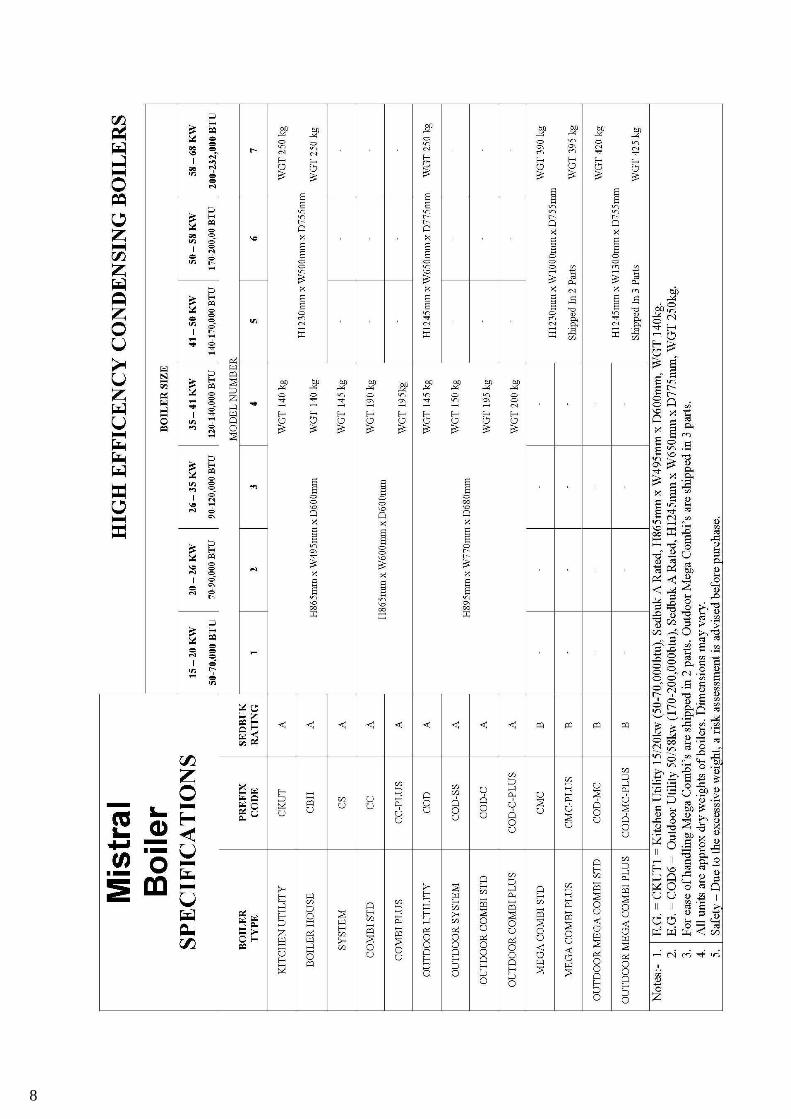
2.1 Introduction .............................................................................................................................. 52.2 Product Description ........................................................................................................... 52.3 Pre Install Procedure ………………………………………………………………………….5-72.3 Specifications And Physical Dimensions …………………….…………………………………….82.4 Heating And Hot Water connection ......................................................................................... 92.5 Safety..................................................................................................................................... 11
2.6 Oil Supply .............................................................................................................................. 112.7 Electrical Connection ............................................................................................. 11
2.8 Useful Information ................................................................................................................. 112.9 Air Supply and Ventilation ..................................................................................................... 112.10 The Control Panel............................................................................................................................... 11
2.11 Burner Lockout ........................................................................................................... 122.12 Starting and Switching off the boiler ......................................................................................132.13 Frost protection............................................................................................................................ 13
2.14 Maintenance................................................................................................................................................14
3.0 Introduction3.1 Suitability ............................................................................................................................... 153.2 Health and safety................................................................................................................... 153.3 Location ................................................................................................................................. 15
4.0 Installation
4.1 Standards and Regulations .................................................................................... 164.2 The Heating System ................................................................................................... 164.3 Domestic Hot Water System. (Combi models) .......................................................................164.4 Electrical Connection .............................................................................................................16
4.5 Air for Combustion and Ventilation ......................................................................... 174.6 The Immersion Heater. (Plus models) ....................................................................................18
5.0 Sealed Systems
5.1 System Regulations....................................................................................................................................205.2 Boiler models ...............................................................................................................................205.3 Heating and hot water systems....................................................................................................205.4 Sealed Primary Systems .............................................................................................................20
5.5 Expansion Vessel Sizing .............................................................................................................205.6 Discharge Pipe and Safety Relief .................................................................................................205.7 System Filling and Commissioning ..............................................................................................20
6.0 Oil Storage and Supply6.1 Regulations............................................................................................................................ 216.2 Fuels ............................................................................................................................................................216.3 Storage Tanks and Locations............................................................................................................ 226.4 Installation Diagrams .................................................................................................................................23
7.0 Flues
7.1 Conventional...............................................................................................................................................24
7.2 Balanced .......................................................................................................................................257.3 Balanced Flue clearances.............................................................................................................26-277.4 Flue Assembly......................................................................................................................................29-30
8.0 Condensate Drain …………………………………………………………………………………….31-32
9.0 Commissioning / Servicing and Maintenance ……………………………………………………..33-3410.0 Fault Finding10.1 Boiler Fault Finding table ...............................................................................................................................35-3811.0 BoilerSpares………………………………………………………………………………………………39-4012.0 Technical/specification …………………………………………………………………………………4213.0 Control Wire Diagrams……………………………………………………………… 43-4715.0 Installation/ Commissioning / Service & guarantee Details .............................................................48-51
1.1 COSHH Regulations 1988This information is for installers and service engineers, as required by the consumer protection act 1987 andthe health and safety at work act 1974.
Every reasonable care has been taken to see that this product has been developed and built to meet these safetyrequirements, when installed in the manner intended.It is the responsibility of those working on this appliance to ensure that all necessary personal protection is used tosafeguard against parts and substances that may be considered hazardous to health and safety, some of whichmay be listed below.
Kerosene and Gas Oil (Mineral Oils) Skin Care Avoid as far as possible any skin contact with mineral oils The lighter fractions of these oils remove the protective grease normally present in the surface of the skin.
This can make the skin liable to crack, and prone to damage. Prolonged exposure may lead to the development of warty swellings or sores. Skin rashes (Oil acne) may
occur on any part of the body where there is mineral oil contact with the skin. Always wash your handsbefore going to the toilet.
Do not delay in seeking medical attention if you suspect any problem. Before working on appliance: use suitable lanolin based creams that may give some protection against the
affects of mineral oil and assist cleaning of skin. Re-apply before work is resumed after each break.
Ingestion Under no circumstances should mineral oils be taken internally. Never ingest any mineral oils. Never siphon by mouth. Never breathe any mineral oil vapours and do not fire the burner in a manner where unburnt vapours can
be discharged into any work area or kitchen.
First Aid If mineral oil is accidentally swallowed, seek immediate medical attention and do not induce vomiting . If mineral oil is splashed into eyes, wash out with running water for at least 10 minutes and seek
immediate medical attention.
Insulation and Rope Seals;Glass Rope, Mineral Wool, Glass Fibre and Ceramic Insulation. The dust and fibres of these materials may be harmful if inhaled. Suppress any dust observed when
removing fired parts by spraying with water. Safety wrap in a sealed plastic bag. Remove from the site anddispose of, in a permitted way.
New parts should only be used as supplied and not be cut or machined. If it’s necessary to cut or drill, afacemask should be worn and the cutting carefully disposed of as above.
Glue, Paint and Sealant These materials present no known hazard, when appliance is used for purposed intended.
1.2 In The Event of Fuel Spillage Stop/switch off all electrical and other ignition risks. Isolate the leak.
Ventilate the area. Smother the spillage using sand, soil or other suitable absorbing material, but not cement. Avoid oil contact with combustible materials. Prevent spilt fuel from entering drains or watercourses. If it
does, warn the Environment Agency, Water suppliers and Fire Service.
HandlingThe products are extremely heavy, and a risk assessment, and plan of action, should be made at each site,prior to the appliance arriving.
1.3 Operation.
This appliance is not intended for the use by persons (including children) with reduced physical, sensory ormental capabilities, or lack of experience and knowledge, unless they have been given supervision orinstruction concerning use of the appliance by a person responsible for their safety. Children should besupervised to ensure that they do not play with the appliance
4
HEALTH AND SAFETY
User Information 2
2.1 IntroductionWe are confident that our company produce the biggest range of domestic oil fired boilers manufacturedin the U.K. Mistral have been manufacturing boilers for than a quarter of a century and been makingcondensing boilers for a number of years. Our extensive experience in condensing technology hasenabled us to produce a new generation of high efficiency condensing boilers. Our unique Y shapedinner waterway allows us to achieve much greater heat transfer and therefore efficiency, whilst at thesame time reducing the resistance in the boiler most commonly found with traditional condensing
boilers which have no internal waterways. This enables a cleaner start up, and therefore reduces thepotential for the appliances to soot up.
The main heat exchanger is made from mild steel 5 mm inner,3 mm outer and the condensing unit ismade from 316 grade stainless steel.
This high specification has been achieved through extensive research and testing to ensure ourproducts achieve the highest quality.
2.2 Product descriptions.Models;-
Standard KUT/BH/1 -7 50 / 232,000 BTU’S(15 -68KW)These appliances are suitable for open vent and sealed system application.
Sealed System CS 1-450/ 140,000 BTU’S (15 -41KW)Incorporates expansion vessel, pressure relief valve, filling loop & circulating pump as standard.
Combination CC1-4 50 / 140,000 BTU’S (15-41KW)Provides for heating and hot water within one unit, priority hot water system. Includes expansion vessel,pressure relief valve and circulating pump as standard, flow rates 17.5 –20 litres @ 35
°C rise and a draw off
between 130 – 500 litres.
Mega Combination CMC5-7 140 / 232,000 BTU’S (41 -68KW)Our unique Mega Combi is used when requirement is for higher flow rates and better draw off. Flow ratesfrom 27-35 litres @ 40
°C rise and a draw off up to 600 litres .Draw off is affected by output and flow rates.
Combination Plus (7 day, two channel programmer supplied)Our unique product on this model is the inclusion of an immersion heater, which can either be used as abackup for hot water, or indeed used to achieve hot water if there is any issue with the burner, or lack of fuelto the appliance. Please note immersion only heats water.Hot water performance will not be the same as when boiler is operated utilising burner.
OutdoorsAre available for all models and are particularly useful when internal space is at a premium, or you simply donot want the unit indoors.
2.3 Pre install procedures and quick reference tips.
Thank you for buying a Mistral product.Please note the following points of added information for your attention.
Non-Condensing / Condensing boilers
1. Please read the manual fully before installing the appliance.2. The products are extremely heavy, and a risk assessment, and plan of action, should be made at each
site, prior to the appliance arriving.3. The appliance is likely to be fixed to the pallet for extra security when shipping. Normally, one screw
each side of the burner, through the base.4. Boiler should be placed on a flat level surface.5. All our Y section units can be ordered as condensing or non-condensing. Prior to filling system,
please check all joints are tight as they may vibrate in transit.6. Before firing the burner, remove main boiler inspection door, and condensing unit door to ensure
baffles have not moved in transit. They should be pushed back level and flush to each other. Failure todo so may affect efficiency, combustion and performance. The condensing baffles must be vertical asyou look at the door. Failure to do this may affect efficiency and combustion. When replacing thedoor, please tighten the bolts to ensure good seal. Only a suitably qualified person should fire / set-up burner.
7. Programmer or link wires must be fitted on all combi`s to operate. Will not operate with-out.
5
USER INFORMATION
Note: Identify the following items from the drawing provided (pages 9-10)
7. Non-Condensing;
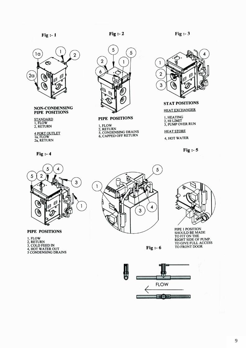
a. Flow and return – Fig. 1
b. Flow and return sockets are as follows;15 / 41 kw.=1’BSP41 / 68 kw. = 1’1/4 BSP
c. A spacer is also needed to take up the distance between the top of the exchanger and the exit for thebalanced flue. For a conventional flue, a flue adapter will need to be ordered.
d. A 4 port outlet exchanger may be ordered as a special. Fig.1
8. Condensing
Condensing, Standard boilers. (see page 39/40 for assembly breakdown).
a. Flow and return – Fig. 2b. Flow and return sockets are as follows;
15 / 26 kw. = 22mm. Dia
26 / 68 kw. = 28mm. Diac. Condensate drain pipes – 22mm. Dia usually 2 off in total, 1 either side of the stainless steel
exchanger, at the rear of the unit, which allows for either left or right exit from boiler to drain.Cap one end off. Fig.2
d. Take note of all stats relevant to the boiler, and ensure they are in the correct pocket.
Note: Standard boiler – 1 / heating stat, 2/ hi limit stat (Fig.3 page 9)
9. A condensing trap is supplied to be fitted on the system – please ensure this is filled with waterand that the pipe work slopes down to drain. Ensure push fit stop end is fitted on condensing outlet notused.
10. A isolating valve must be fitted to the oil line, inside the casing, and isolating ball valves should befitted on the flow and return pipes to make repairs or servicing parts easier.
11. Make sure the correct amount of inhibitor is used when filling the system, and checked annually.
12. Frost stats should be fitted to all boilers, where there is a risk of low temperatures.
13. Condensing Combi;
a. Flow and return – Fig. 4b. Flow and return sockets are as follows;
15 / 26 kw. = 22mm dia.26 / 68 kw. = 28mm dia.
c. Condensate drain pipes as above.
d. Take note of all stats relevant to the boiler, and ensure they are in the correct pocket.1/ heating stat, 2/ hi limit stat, 3/ pump overrun stat, 4/ hot water stat (see Fig. 3, page 9)
e. Check the pipework position, and direction of flow. Please ensure that when making up the flowpipe from the diverter valve, that you avoid blocking any parts of the boiler from being removed ata later stage. Fig. 5
f. Check arrow is pointing in the correct flow direction on the pump. Fig. 8g. Check flow switch is fitted in an aligned position to the pipe, and also that the arrow is pointing in the
direction of the flow. Fig. 6
h. Important – Hot water – the dial indicator for this should be set for position 1, unless there is a
requirement for the water to be hotter. The boiler produces water at a high temperature to help
against bacteria in the pipes, or overcome an extended run of pipe to the tap, and also to give the best
overall performance achievable for a small store, in terms of flow rate at a given rise of
temperature.
There will also be a difference to the incoming water temperature between the summer and
winter, which will have an effect on the tap temperature.
If you feel that the temperature at the tap, is higher than you would like, we suggest you consider
fitting either a mixer valve which can be manually operated or a thermostatic valve, which will give a
more consistent result. These can be fitted either at individual taps, or alternatively, anywhere from
the boiler onwards, if you would like all the water temperatures reduced.
If a mixer or thermostatic valve is fitted it may be necessary to fit a pipe thermostat to the boiler.
6
i. The expansion vessel supplied with the unit is specifically to protect the boiler, and additional vessels may berequired depending on the size of the system being fitted.
Water content = 15 / 41 kw Combi = exch = store = 20 + 30 = app. 50 litresWater content = 41 / 68 kw Combi = exch = store = 25 + 95 = app. 120 litres
14. The combi boilers are not designed for 4 port operation.
15. Kut`s will come as 2 port or 4 port, we recommend you always specify on the order to confirm.T Blanking plugs will be supplied free issue.
16. All outdoor models should be resealed around all pipes / wires to ensure no water ingress.
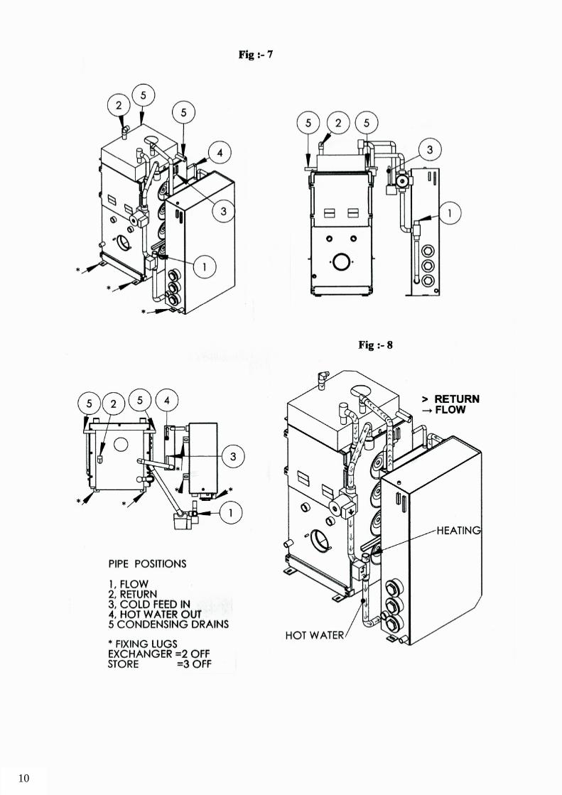
17. Condensing Mega Combia. For ease of transit, and on site mobility, the Mega is in 2 separate cased parts. The majority of the combi
information available above is also relevant to the Mega Combi.
b. This unit will require a certain amount of fabrication to build on site, and although the pipework / pump /divertor valve fittings are supplied, they are not fitted, due to excessive strain on the unit during shipping.
c. When ready to fit together, we suggest the base fixings shown, (Fig 7) are loosened, and the pipework isassembled in the correct position as a mock up.The heat store and the exchanger may have to be slightly adjusted to ensure everything fits together.When you are satisfied that the unit is assembled correctly, tighten all nuts down, and make pipework good.See Fig 7 / 8.
18. For all combi`s – we recommend using a 7 day 2 channel programmer which can be supplied by Mistral. Althoughthe wires can be linked for the hot water to run continuous, this is not recommended.
To ensure maximum efficiency of the boiler full programmable controls are recommended.Mistral can supply a 7 day 2 channel programmer to give full control of heating and water.
19. We hope that this list has been of some help, however, if you need any more assistance pleasefeel free to call Mistral Boilers, and our technical department will try to resolve any problem youmay encounter.
7
8
9
10
2.5 Safety. Please refer to figure 1.0 Health and Safety on page4.
2.6 Oil Supply.
Fuels. This range of boilers is designed to burn on BS 2869 Part2, Class C2 28 Sec Kerosene.
2.7 Electrical Connection. Your boiler should be connected to the electrical supply via a fused isolator (5 amp
fuse), located on an adjacent wall, and on Mistral Combi Plus immersion heater version should be connecteddirectly to your consumer unit (20 amp ELCB circuit), via a double pole isolator located on adjacent wall.
Always Isolate Electrical Supply Before Internal Cover is removed.2.8 Useful Information.
Date of Installation ...............................................................Boiler Model ..................................................................
Boiler Serial Number .............................................................
Oil Type to BS2869 Class C2 28 Sec KeroseneOil Tank Capacity: ............................................................
2.9 Air Supply and VentilationThe boiler can be fitted with the following flue type:
Conventional Flue
This type requires a permanently open air vent; which must not be closed off, to supply air combustion andto allow the flue system to work.Conventional flue system must be suitable to be used on an oil fired condensing boiler. Please contact fluesupplier or manufacturer.
Balanced FlueThis type does not require a permanently open air vent supply, however, ventilation may be required ifappliance is enclosed within a cupboard or small compartment to prevent the appliance from over heating.Reference may have changed since publication. It is the responsibility of the installer to checkcurrent regulation before installing
~ WARNING! PLEASE ENSURE COMBUSTION AIR VENTS AND FLUE WAYS ARE
NOT OBSTRUCTED OR CLOSED.
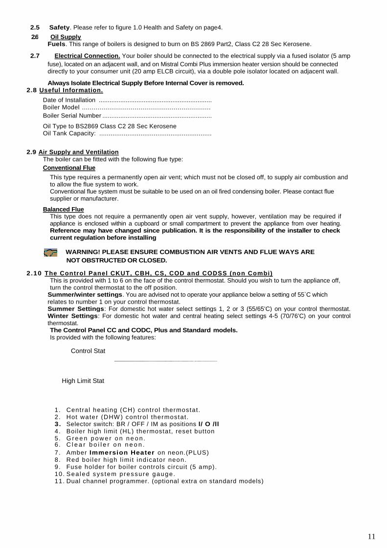
2.10 The Control Panel CKUT, CBH, CS, COD and CODSS (non Combi)This is provided with 1 to 6 on the face of the control thermostat. Should you wish to turn the appliance off,turn the control thermostat to the off position.
Summer/winter settings. You are advised not to operate your appliance below a setting of 55`C whichrelates to number 1 on your control thermostat.Summer Settings: For domestic hot water select settings 1, 2 or 3 (55/65’C) on your control thermostat.Winter Settings: For domestic hot water and central heating select settings 4-5 (70/76’C) on your controlthermostat.The Control Panel CC and CODC, Plus and Standard models.Is provided with the following features:
1. Central heat ing (CH) control thermostat .2. Hot water (DHW ) control thermostat .3. Selector switch: BR / OFF / IM as positions l/ O /ll4. Boi ler high l imit (HL) thermostat, reset button5. G r e e n p o w e r o n n e o n .6. C l e a r b o i l e r o n n e o n .
7. Amber Immersion Heater on neon.(PLUS)8. Red boi ler high l imi t indicator neon.9. Fuse holder for boi ler controls circuit (5 amp).10. Sea led sys tem pressure gauge .11. Dual channel programmer. (optional extra on standard models)
Stat
Reset
11
Control Stat
High Limit Stat
2.10.1 The central heating thermostat has a dial knob for boiler temperature control in the range 55/82°C. Thisis shown on the knob as number 1 to 6 and should you wish to turn the boiler off for a short period, turn theknob to the OFF position.
Settings. You our advised not to operate your boiler below 55°C which relates to setting number 1 on yourcontrol knob.For normal heating, select between number 4 and 5 (70/76°C) on your control knob. In severe weather
conditions it may be necessary to select number 6 (82°C) on your control knob.
2.10.2 The hot water control thermostat This range is from 55-82°C and has numbers 1 to 6. The use of thiscontrol allows you to limit the stored water temperature, select the number in the range (1 = hot to 6 = veryhot), that best suits your needs.
Note! water temperature will be less in colder periods due to much c older mains water passingthough the heat exchanger. You may have to adjust/decrease the flow at source (tap) to increasewater temperature.
However as the hot water production from this boiler is highly efficient you find under certaincircumstances of low flow rate, that the water temperature at the point of use may be for a short period toohigh. Should this prove to be a nuisance, your installer, will be able to advise the uses of an appropriatetemperature mixer valve.
2.10.3 The boiler selector switch. Controls either the boiler On or immersion heater On, (immersion heater onlyapplicable to plus models ) with an intermediate off position and is indicated on the switch as: l/ O /ll. Theneon indicators show the selection. Switching the selector to O and ll also removes the power to theprogrammer.
2.10.4 High Limit Thermostat
Under the small black finger tight cap located to the side of the thermostat is housed the reset button forthe high limit thermostat. Should it be necessary to reset, wait until the appliance has sufficiently cooleddown to allow for the thermostat to reset. Should this persist, contact your installer or service engineer.
2.10.5Dual Channel Programmer. (Combi models)Provides full control over heating and hot water.Please note that programmer is an optional extra on the standard model combi.
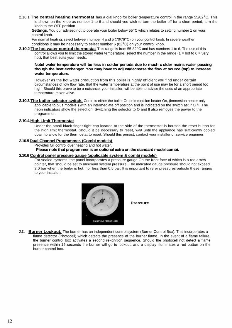
2.10.6 Control panel pressure gauge (applicable system & combi models)For sealed systems, the panel incorporates a pressure gauge On the front face of which is a red arrowpointer, that should be set to minimum system pressure. The indicated gauge pressure should not exceed2.0 bar when the boiler is hot, nor less than 0.5 bar. It is important to refer pressures outside these rangesto your installer.
2..11 Burner Lockout. The burner has an independent control system (Burner Control Box). This incorporates aflame detector (Photocell) which detects the presence of the burner flame. In the event of a flame failure,the burner control box activates a second re-ignition sequence. Should the photocell not detect a flamepresence within 15 seconds the burner will go to lockout, and a display illuminates a red button on theburner control box.
Pressure
12
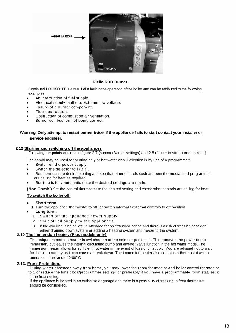
Riello RDB Burner
Continued LOCKOUT is a result of a fault in the operation of the boiler and can be attributed to the followingexamples: An interruption of fuel supply. Electrical supply fault e.g. Extreme low voltage. Failure of a burner component. Flue obstruction. Obstruction of combustion air ventilation. Burner combustion not being correct.
Warning! Only attempt to restart burner twice, if the appliance fails to start contact your installer or
service engineer.
2.12 Starting and switching off the appliancesFollowing the points outlined in figure 2.7 (summer/winter settings) and 2.8 (failure to start burner lockout)
The combi may be used for heating only or hot water only. Selection is by use of a programmer: Switch on the power supply. Switch the selector to l (BR). Set thermostat to desired setting and see that other controls such as room thermostat and programmer
are calling for heat as required. Start-up is fully automatic once the desired settings are made.
(Non Combi) Set the control thermostat to the desired setting and check other controls are calling for heat.
To switch the boiler off.
Short term:1. Turn the appliance thermostat to off, or switch internal / external controls to off position.
Long term:1. Swi tch of f the appl iance power supply.
2. Shut of f o i l supply to the appl iances.
3. If the dwelling is being left un-attended for an extended period and there is a risk of freezing considereither draining down system or adding a heating system anti freeze to the system.
2.10 The immersion heater. (Plus models only)
The unique immersion heater is switched on at the selector position ll. This removes the power to theimmersion, but leaves the internal circulating pump and diverter valve junction in the hot water mode. Theimmersion heater allows for sufficient hot water in the event of loss of oil supply. You are advised not to waitfor the oil to run dry as it can cause a break down. The immersion heater also contains a thermostat which
operates in the range 40-80°C
2.13. Frost Protection.During winter absences away from home, you may lower the room thermostat and boiler control thermostat
to 1 or reduce the time clock/programmer settings or preferably if you have a programmable room stat, set itto the frost setting.If the appliance is located in an outhouse or garage and there is a possibility of freezing, a frost thermostatshould be considered.
ResetButton
13
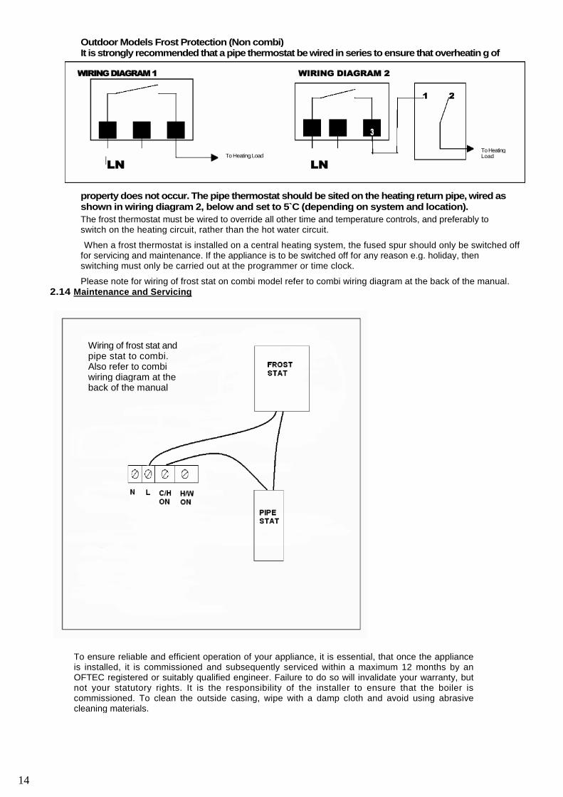
Outdoor Models Frost Protection (Non combi)It is strongly recommended that a pipe thermostat be wired in series to ensure that overheatin g of
property does not occur. The pipe thermostat should be sited on the heating return pipe, wired asshown in wiring diagram 2, below and set to 5`C (depending on system and location).
The frost thermostat must be wired to override all other time and temperature controls, and preferably toswitch on the heating circuit, rather than the hot water circuit.
When a frost thermostat is installed on a central heating system, the fused spur should only be switched offfor servicing and maintenance. If the appliance is to be switched off for any reason e.g. holiday, thenswitching must only be carried out at the programmer or time clock.
Please note for wiring of frost stat on combi model refer to combi wiring diagram at the back of the manual.2.14 Maintenance and Servicing
To ensure reliable and efficient operation of your appliance, it is essential, that once the applianceis installed, it is commissioned and subsequently serviced within a maximum 12 months by anOFTEC registered or suitably qualified engineer. Failure to do so will invalidate your warranty, butnot your statutory rights. It is the responsibility of the installer to ensure that the boiler iscommissioned. To clean the outside casing, wipe with a damp cloth and avoid using abrasivecleaning materials.
WIRINGDIAGRAM1 WIRING DIAGRAM 2
LNTo Heating Load
LN
3
1 2
To HeatingLoad
Wiring of frost stat andpipe stat to combi.Also refer to combiwiring diagram at theback of the manual
14
Introduction
3.1 Suitability.
Mistral oil fired boilers are fully automatic, horizontally fired pressure jet boilers, complying with Europeandirectives for boiler efficiency, low voltage and EMC and are designed for use as follows:
1. Indirect, open-vented central heating and hot water systems.
2. Indirect, un-vented sealed central heating and hot water system.3. For maximum system operating pressure up to 3 bar.4. For connection to approved conventional or factory made chimney.
5. For use with Mistral own balanced f lue system6. As a replacement for existing boilers or as part of a new installation.
3.2 HealthandSafety.Please refer to the COSHH information printed on the inside cover of the manual.
In the interest of safety reliability and efficiency the appliance should be installed and commissioned by anOFTEC or suitably qualified engineer.
The equipment supplied by Mistral Boilers in the way of boiler or flue, should not be modified or usedoutside the scope of its suitability, unless described within this manual or through direct discussion withMistral.
Electrical wiring to the boiler and heating system should be undertaken by a suitably qualified electricianand comply with the last wiring regulations BS7671. No attempt should be made to modify or change theinternal wiring of the boiler.
3.3 Location.
The HearthThe boiler must stand on a firm level hearth which complies with current building regulation. The basetemperature of the appliance does not exceed 85`C. If the boiler is to be positioned on a hearth ofcombustible material, suitable protection should be placed underneath which is non combustible andimpervious to oil.
Sit ing.The noise level of the appliance is low and so makes them ideally suitable for siting within the kitchen, theutility room or garage. As some people are more sensitive to noise than others, it is good practice todiscuss the intended location beforehand.
When choosing the location for a condensing boiler special consideration must be given to the positioning ofthe flue terminal. Care should be taken to locate it so as to prevent either the end user or their neighboursperceiving the plume to be a nuisance. It should be noted that the normal statutory clearances requiredaround low level flue terminals may not be sufficient to cope with plume dispersal from a condensing boiler.The following points should be considered:
1. Plumes can extend out horizontally and can also drift out to the sides and above the terminal. Care needsto be taken therefore to avoid the plume reaching adjacent surfaces, particularly windows and neighboursdwellings.
2. Flue terminals need to be located where air can pass freely across them to disperse vapour.
3. The effect of the moisture generated must be considered in relation to possible corrosion of metal parts itmight reach and to the possible formation of ice on pathways in freezing conditions.
4. Keep flue terminals a minimum of 1 m (horizontally) from openings in the building.
5. Do not install flue terminals directly below a window. (see diagram page 27/28)
6. Do not install flue terminals next to a door. (see diagram page 27/28)
7. Do not install flue terminals within 1 m of ventilated soffits or eaves. (see diagram page 27/28)
8. Keep flue terminals at least 1 m away from a surface or boundary facing a terminal.
(see diagram page 27/28)
Avoidance of any potential nuisance can normally be achieved by utilising one of the many differing flueoptions available.For condensing boilers, the same requirements apply for installation with regard to cleaning and flushing andproviding inhibitors, as are followed for any other boiler
15
INTRODUCTION
4.1. Standards and Regulations.
The installation of this boiler must comply with the latest edition of the following standards:BS 799:5 Specification for Oil Storage Tanks.
BS 4543 Pt 1 & 3 Factory made Chimneys.
BS 5410 Pt 1 Oil Installations under 44kW.BS-EN –
12828128312003
Forced Circulation Hot Water Central Heating Systemsfor Domestic Premises.
BS 7074 Pt 1 & 7 Sealed System Components and Codes ofPractice.
BS 7593 Code of Practice for Treatment of Central Heating Waterin DHWS.
BS 7671 Electrical Wiring Regulations.
THE BUILDING REGULATIONS
Part J & L England and Wales.
Part F Section 111 Scotland.
Part L Northern Ireland.The Control of Pollution (Oil)Regulations
BS 5955:8 Installation, Plastic Pipes and Fittings
Special consideration should be given for condensate removal and plume dispersal. The installation of oilfiring condensing boilers is the same as for non-condensing boilers.BS 5410: Part 11997 gives the requirements for domestic boiler and oil storage installations.
For condensing boilers the same requirements apply for installation with regard to cleaning and flushing andproviding inhibitors as are followed for any other boiler.
4.2. The Heating System.This boiler can be used for a new installation or as a replacement fitted to an existing installation.
Ensure that the system is thoroughly cleaned and flushed through prior to filling and for long term protectiona suitable corrosion and scale inhibitor should be added to the primary water.Kettling and system noises can best be avoided with the removal of swarf and residues prior to filling withclean water and the addition of a proprietary system inhibitor, before first firing, is strongly recommended.
To avoid nuisance over temperature tripping out of the boiler limit thermostat, due to reduced or no waterflow through the boiler whilst the burner is firing, it is strongly advised that the control system should bewired so that the burner is switched off at the same moment as the circulating pump.
Where thermostatic radiator valves are employed, these may well cause reduced return flow to the boiler asthey close down. To avoid affecting the boiler flow, it is preferable to include in the system, a by-pass loopbetween the flow and return, which incorporates a proprietary by-pass valve that is sensitive to the changein pressure.
Before filling the system, ensure that any unused sockets have been plugged and the boiler drain downpoint is closed.Garage Installations are dealt with in the OFTEC Technical advice publication Tl/1 27.
4.3. Domestic Hot Water System. (Combi models)The cold mains inlet fittings provides a 15 mm compression joint on the CC1, CC2, CC3 and CC4 (15-41kw)models and 22 mm on mega combi range MC5, MC6, MC7 (41-68).
The water supply pressure to the boiler should be within the range of 1.0 to 3.0 bar. If pressure exceeds 3.0bar fit a pressure reducing valve.Cold Water Supply and Treatment. To minimise scale formation in the plate heat exchanger it is importantto know how hard the water supply is. This hardness information is available from the local water company.Where water hardness of over 150ppm is expected, it is recommended that water treatment is fitted. Thiswould preferably be a water softener. There are also signal type water conditioners that are connected toelectrical supply external to the boiler. Without treatment it is to be expected that the natural scale build upwill with time, reduce the heat transfer effiency of the plate heat exchanger.
4.4. Electrical Connection. (Non combi and combi standard)The external electrical supply required is: 230V, 1 ph, 50Hz,The supply must be fused at 5 Amps by a double pole isolation switch, with a contact separation for eachpole of 3mm and with shuttered sockets. Mounted adjacent to the boiler, it must isolate all of the boiler andcontrol system.
16
The supply connection to the control panel is through a removable three way plug located in the base of thecontrol panel. There is no need to enter the control panel for supply connection.Room or frost thermostats used should be able to switch mains supply voltage and have a contact rating ofat least 10 amps.
Electrical Connection. (Combi plus)The external electrical supply required is: 230 V, 1 ph, 50Hz,The supply to combi plus must be through a direct spur to the consumer unit and ELCB fused at 20amps.This provides for the immersion heater application, the boiler being protected by a 5 amp fuse holder on theunderside of the control panel.
There should be adjacent to the boiler a suitable means of isolation, via a double pole isolation switch, witha contract separation for each pole of 3 mm and shuttered sockets. It must isolate all of the boiler andcontrol system.
Wiring connections. There’re only 2 connections required.1. Supply connection to the control panel is through a removable three way plug located in the base of
the control panel. There is no need to enter the control panel for supply connection. You are advised torun heat resisting cable with a cable size of 2.5 mm, this to provide for the integral pre- wired 3kWImmersion Heater within the thermal store.
2. Room thermostat / Programmerable room stat. (Combi models) the thermostat selected should beable to switch mains supply voltage and have a contract rating of at least 10 amps. The connection is tothe 12 way terminal strip numbers 11 and 12 having first removed the red link.
4.5. Air for Combustion and Ventilation.The provision of a permanent and adequate air supply is essential for the safe and efficient operation of theboiler, and must cater as follows: Air for combustion and to allow the flue to evacuate all the flue products. Air for ventilation to prevent overheating, if the boiler is installed in a confined space
Or compartment.
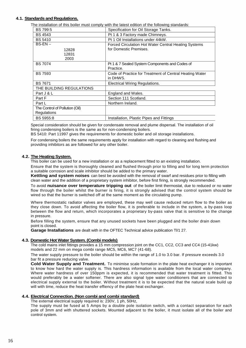
Air for combustion (conventional flue)British Standard Code of Practice BS5410: pt1. Require a permanent opening from outside, into the roomcontaining the boiler of 550mm2 for each kW of boiler maximum output.
Where a stabiliser is fitted 1 100mm2/kW is required, but not if the boiler is in a ventilated compartment.Preferably located at high level, to avoid discomfort to the occupants and any possibility of being blocked offto prevent draughts.
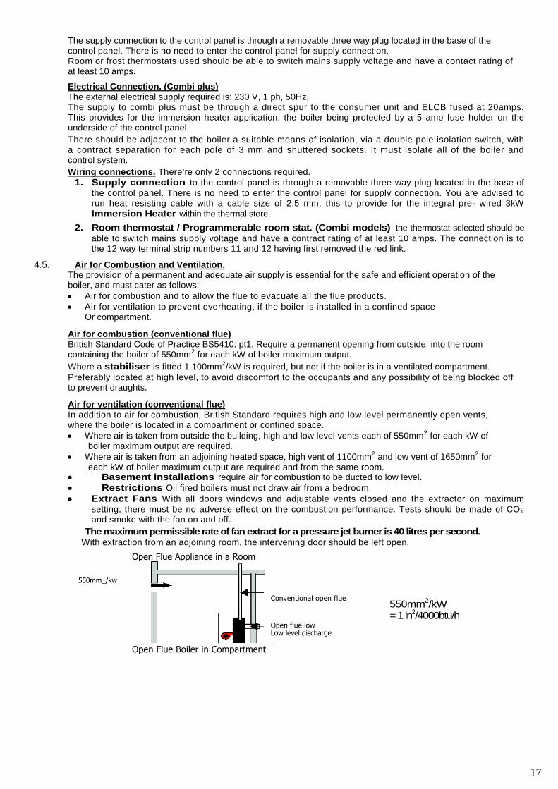
Air for ventilation (conventional flue)In addition to air for combustion, British Standard requires high and low level permanently open vents,where the boiler is located in a compartment or confined space. Where air is taken from outside the building, high and low level vents each of 550mm2 for each kW of
boiler maximum output are required. Where air is taken from an adjoining heated space, high vent of 1100mm2 and low vent of 1650mm2 for
each kW of boiler maximum output are required and from the same room. Basement installations require air for combustion to be ducted to low level. Restrictions Oil fired boilers must not draw air from a bedroom. Extract Fans With all doors windows and adjustable vents closed and the extractor on maximum
setting, there must be no adverse effect on the combustion performance. Tests should be made of CO2
and smoke with the fan on and off.
The maximum permissible rate of fan extract for a pressure jet burner is 40 litres per second.With extraction from an adjoining room, the intervening door should be left open.
Open Flue Appliance in a Room
550mm_/kw
Conventional open flue
Open flue lowLow level discharge
550mm2/kW=1in2/4000btu/h
Open Flue Boiler in Compartment
17
Compartment Ventilated From Room Compartment Ventilated from Outside
Balanced Flue Boiler in Compartment
Compartment Ventilated From Room Compartment Ventilated from Outside
4.6 The Immersion Heater. (Plus models)The Immersion Heater is pre- wired to the boiler control panel and requires no further attention.It’s internal thermostat operates independently to all other boiler thermostats and is set at 65°C.When the immersion heater is selected on the front of the control panel switch: position ll, the integralcirculating pump is energised. It remains in operation throughout this selection, to provide heat transfer atthe plate heat exchanger.
Warning! Do not operate the immersion heater without the heating system being first, filled with water andbled of air
1650
mm_/kw
1100mm_/kw
1100mm_/kw
550mm_/kw
550mm_/kw
The above information supplied by OFTEC
mm_/kw
1100
mm_/kw
1100
550mm_/kw
550mm_/kw
18
5.1. System Regulations. In addition to the installation standards and regulations outlined earlier in 4.1. SealedSystem installations must comply with the latest edition of: BS 7074 pt 1. Application, selection and installation of expansion vessels and ancillary equipment for
sealed systems. BS 7074 pt 7. Code of practice for sealed systems.
5.2. The Boilers: Models CKUT, CBH, COD are suitable for incorporation in a sealed un-vented heating or hotwater system as they are equipped with a manual reset limit thermostat. They do not however contain withintheir construction any of the components required for filling or water pressure safety. Models CC, CODC, ODCS and CS These boilers are supplied with all the necessary components for
connection to a sealed un-vented heating or hot water system as follows: Expansion Vessel. Pre charged at 1.0 bar (14.5 psi) Is suitable for a static head of up to 10.2m,
measured from the highest point of the system; usually the top of the bedroom radiators, to the mid pointof the vessel.
For other static heads the pre-charge must be adjusted, either by lowering to 0.5 bar for 5.1 m, orincreasing to 1.5 bar for 15.3m. For this purpose a standard tyre valve is provided on the expansionvessel. Measurement is achieved using a tyre gauge, with the vessel disconnected from the system orthe system empty of water. Higher pressures are made by pumping up with a conventional foot pump.
The pre-charge must not exceed 1.5 bar.
Pressure Relief Valve. Factory set at 3.0 bar (43.5 psi.), and located on the front left hand side ofthe heat exchanger.
Circulating Pump. Grundfos three speed variable head with heavy duty ball isolating valves.Mounted on the internal boiler flow pipework. Direct installer connection to 22mm compression.
Automatic Air Vent. Pressure Gauge 0-4 bar. Control panel mounted and connected to the pressure relief valve tapping. Filling and Make-up Loop. Limit Thermostat – Manual Reset.
Setting at 11 0°C ±6
°C. Reset button located on the front face of the control panel under the black finger
tight knob. Should the boiler overheat and the limit thermostat trips it can not be reset until the boiler hascooled sufficiently. See section 11 for spares components
5.3. Heating and Hot Water Systems.The CC, CODC, ODCS and CS models are specifically designed for use on sealed un-vented systems.They can however be used on an open vented system in accordance with the normal requirementsapplicable to this type of installation.
The boilers incorporate an in-built circulating pump.Thermostatic radiator valves and lock shield valves must be suitable for the higher system operatingpressures. System Filling Point and Make-up.The connection point on the boiler may be capped off and an alternative location provided elsewhere on alow point of the system, if preferred. This must however be in accordance with local water undertakingregulations.
The make-up provision on the system boilers for replacement of lost water is through the filling loop.However, other means can be provided via a make-up vessel or tank. This would be mounted in a higherposition than the top point of the system and connected through a non-return valve into the system. On thereturn side of either: the hot water cylinder or all of the radiators.Loop must be disconnected from one of its connections when not in use.
Mains water Connection. There must be no connection to the mains water supply other than throughthe temporary filling loop connection at the time of filling or recharging.
Hot Water Storage Vessel.This should be of the indirect coil type or a direct cylinder fitted with immersion califierwhich are suitable for the intended system pressure of 0.35 bar above the safety relief valvesetting. That is 3.65 bar.
5.4. Sealed Primary Systems.
The pressure gauge mounted on the control panel indicates the system pressure once cold chargedand during the heating cycle. It also has a red arrow pointer that is positioned to indicate the coldcharge point of the system and serves as a warning to indicate loss of system water. When theboiler is fired the system pressure rises and should not rise above 2.3 bar. If it does it indicatesinsufficient expansion vessel capacity.The expansion vessels initial charge must not be less than the static head pressure of the system.
19
SEALED SYSTEMS
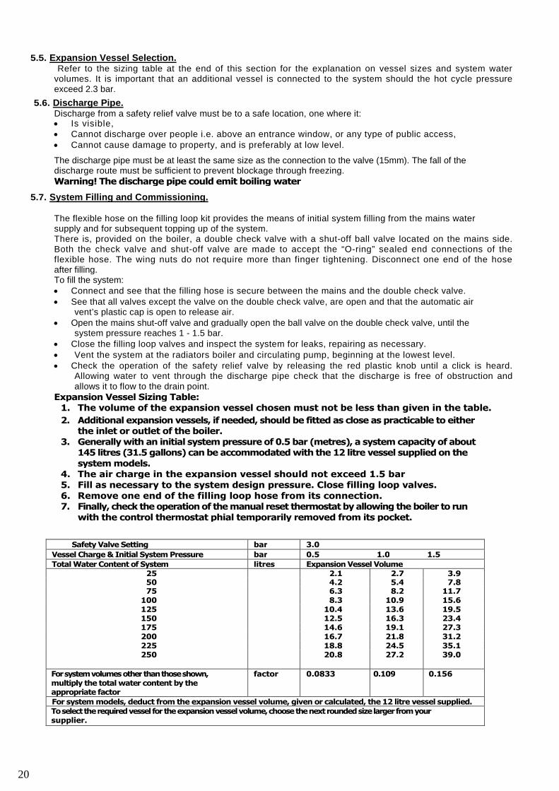
5.5. Expansion Vessel Selection.Refer to the sizing table at the end of this section for the explanation on vessel sizes and system water
volumes. It is important that an additional vessel is connected to the system should the hot cycle pressureexceed 2.3 bar.
5.6. Discharge Pipe.Discharge from a safety relief valve must be to a safe location, one where it: Is visible, Cannot discharge over people i.e. above an entrance window, or any type of public access, Cannot cause damage to property, and is preferably at low level.
The discharge pipe must be at least the same size as the connection to the valve (15mm). The fall of thedischarge route must be sufficient to prevent blockage through freezing.Warning! The discharge pipe could emit boiling water
5.7. System Filling and Commissioning.
The flexible hose on the filling loop kit provides the means of initial system filling from the mains watersupply and for subsequent topping up of the system.There is, provided on the boiler, a double check valve with a shut-off ball valve located on the mains side.Both the check valve and shut-off valve are made to accept the “O-ring” sealed end connections of theflexible hose. The wing nuts do not require more than finger tightening. Disconnect one end of the hoseafter filling.To fill the system: Connect and see that the filling hose is secure between the mains and the double check valve. See that all valves except the valve on the double check valve, are open and that the automatic air
vent’s plastic cap is open to release air. Open the mains shut-off valve and gradually open the ball valve on the double check valve, until the
system pressure reaches 1 - 1.5 bar. Close the filling loop valves and inspect the system for leaks, repairing as necessary. Vent the system at the radiators boiler and circulating pump, beginning at the lowest level. Check the operation of the safety relief valve by releasing the red plastic knob until a click is heard.
Allowing water to vent through the discharge pipe check that the discharge is free of obstruction andallows it to flow to the drain point.
Expansion Vessel Sizing Table:1. The volume of the expansion vessel chosen must not be less than given in the table.
2. Additional expansion vessels, if needed, should be fitted as close as practicable to eitherthe inlet or outlet of the boiler.
3. Generally with an initial system pressure of 0.5 bar (metres), a system capacity of about145 litres (31.5 gallons) can be accommodated with the 12 litre vessel supplied on thesystem models.
4. The air charge in the expansion vessel should not exceed 1.5 bar5. Fill as necessary to the system design pressure. Close filling loop valves.6. Remove one end of the filling loop hose from its connection.7. Finally, check the operation of the manual reset thermostat by allowing the boiler to run
with the control thermostat phial temporarily removed from its pocket.
Safety Valve Setting bar 3.0
Vessel Charge & Initial System Pressure bar 0.5 1.0 1.5
Total Water Content of System litres Expansion Vessel Volume25 2.1 2.7 3.950 4.2 5.4 7.875 6.3 8.2 11.7
100 8.3 10.9 15.6125 10.4 13.6 19.5150 12.5 16.3 23.4175 14.6 19.1 27.3200 16.7 21.8 31.2225 18.8 24.5 35.1250 20.8 27.2 39.0
Forsystemvolumes otherthanthoseshown,multiply the total water content by theappropriate factor
factor 0.0833 0.109 0.156
For system models, deduct from the expansion vessel volume, given or calculated, the 12 litre vessel supplied.Toselecttherequiredvessel for theexpansion vesselvolume,choosethenextroundedsize largerfromyoursupplier.
20
Oil and Supply
6.1 Regulations
BS 5410: pt 1
BS 799: pt 5. Steel Tanks. OFST200.OFS T100: Plastic Tanks.
BS 2871: pt 1 Table Y. Copper Tube.BS 864: pt 2. Flared Fittings.
Building Regulations – Part L & J.
Other Technical Publications from OFTEC.
T I / 1 3 0 : R e m o t e t a n k f i l l ; t e r r a c e d h o u s i n g .T I / 1 3 1 : P o s i t i o n o f d o m e s t i c t a n k s .T I / 1 3 3 : E n v i r o n m e n t a l s p i l l a g e r i s k a s s e s s m e n t .
T I / 1 3 4 : U n d e r g r o u n d o i l s u p p l y p i p e s .
6.2. Fuels.
The burner is supplied set with the appropriate nozzle and pump pressure for the mid range of the boiler tofire Class C2 Kerosene to BS2869 pt 2,The burner must not be modified to burn other fuels, unless Mistral Boilers is consulted with regard tosuitability.
6...3 Oil supply pipes.
Oil enters the boiler side casing low down, either side to suit the installation. In the interests of safety, avoidpassing the flexible burner oil line through the holes in the casing panels, the joint to the copper supply ismade inside the casing.
The oil feed can be a single gravity feed, two pipe suction lift, or single pipe suction lift with DEAERATOR.Pipe work under the ground should be joint free and where appropriate use plastic covered copper tube.Exposed pipe work must be protected against accidental damage and fire.
Do not uses solder fittings in the oil line.Always flush out the oil line before connecting to the burner pump.Components:Oil filters should always be fitted to the oil line. One incorporated in the sight of the gauge assembly at thetank and another (of the paper element type) close by; but not inside, the boiler casing, especially if this is areplacement boiler installation using existing pipe work and tank.Shut off cock, close to the boiler to allow burner and filter servicing, without draining down.Fire valve, is an essential part of the installation. The valve should be located just outside the building atthe point of entry. It is activated by a remote sensor phial which is positioned within the boiler casing andover the burner. The safe routing of the capillary tube to avoid accidental damage is important. Variouslengths of capillary are available.
The use of solder head shut-off valves is not recommended.Overfill alarms and remote contents gauges.Overfill alarms are essential when the delivery point and vent pipe are remote from each other.Remote contents gauges transmit the oil level to a display unit inside the house.
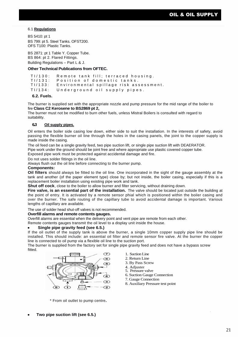
Single pipe gravity feed (see 6.5.)If the oil outlet of the supply tank is above the burner, a single 10mm copper supply pipe line should beinstalled. This should include: an essential oil filter and remote sensor fire valve. At the burner the copperline is connected to oil pump via a flexible oil line to the suction port.The burner is supplied from the factory set for single pipe gravity feed and does not have a bypass screwfitted.
1. Suction Line2. Return Line3. By Pass Screw4. Adjuster5. Pressure valve6. Suction Gauge Connection7. Gauge Connection8. Auxiliary Pressure test point
* From oil outlet to pump centre.
Two pipe suction lift (see 6.5.)
21
OIL & OIL SUPPLY
If the oil outlet of the supply tank is below the burner, a twin pipe 10mm copper supply system is suitable.This should include on the suction line: the essential oil filter, remote fire sensor and a spring loaded non-return oil valve.Connections are to the suction and return ports of the burner pump via two flexible oil lines. The non-returnvalve prevents drain back to the supply tank which can occur during maintenance or after a long period ofshut down.
The oil pump must have its internal bypass screw fitted. This is supplied loose with the burner.The return line should terminate at the same level as the suction line and enter from the top of the tank; alsowithin the tank the return line should have a small cut or hole to prevent siphoning.
No valves or restrictive fittings are to be fitted to the return line as they could blow the pump seals.
Pipe runs (metres) and essential fittings
Fire Valve Yes
Filter Yes
Non-return valve Yes
Bypass screw Yes fitted
Oil lift (metres)0
0.5
11.52
33.5
8mm I/D pipe run353025201586
Maximum lift 4 metres
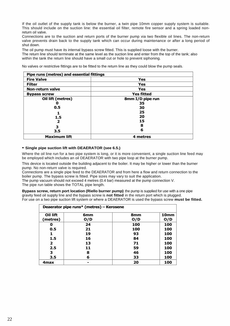
• Single pipe suction lift with DEAERATOR (see 6.5.)
Where the oil line run for a two pipe system is long, or it is more convenient, a single suction line feed maybe employed which includes an oil DEAERATOR with two pipe loop at the burner pump.
This device is located outside the building adjacent to the boiler. It may be higher or lower than the burnerpump. No non-return valve is required.Connections are a single pipe feed to the DEAERATOR and from here a flow and return connection to theboiler pump. The bypass screw is fitted. Pipe sizes may vary to suit the application.The pump vacuum should not exceed 4 metres (0.4 bar) measured at the pump connection V.The pipe run table shows the TOTAL pipe length.
Bypass screw, return port location (Riello burner pump) the pump is supplied for use with a one pipegravity feed oil supply line and the bypass screw is not fitted in the return port which is plugged.For use on a two pipe suction lift system or where a DEAERATOR is used the bypass screw must be fitted.
Deaerator pipe runs* (metres) – Kerosene
Oil lift(metres)
6mmO/D
8mmO/D
10mmO/D
0 24 100 100
0.5 21 100 100
1 19 93 100
1.5 16 84 100
2 13 71 100
2.5 11 59 100
3 8 46 100
3.5 6 33 100
4max - 20 100
22
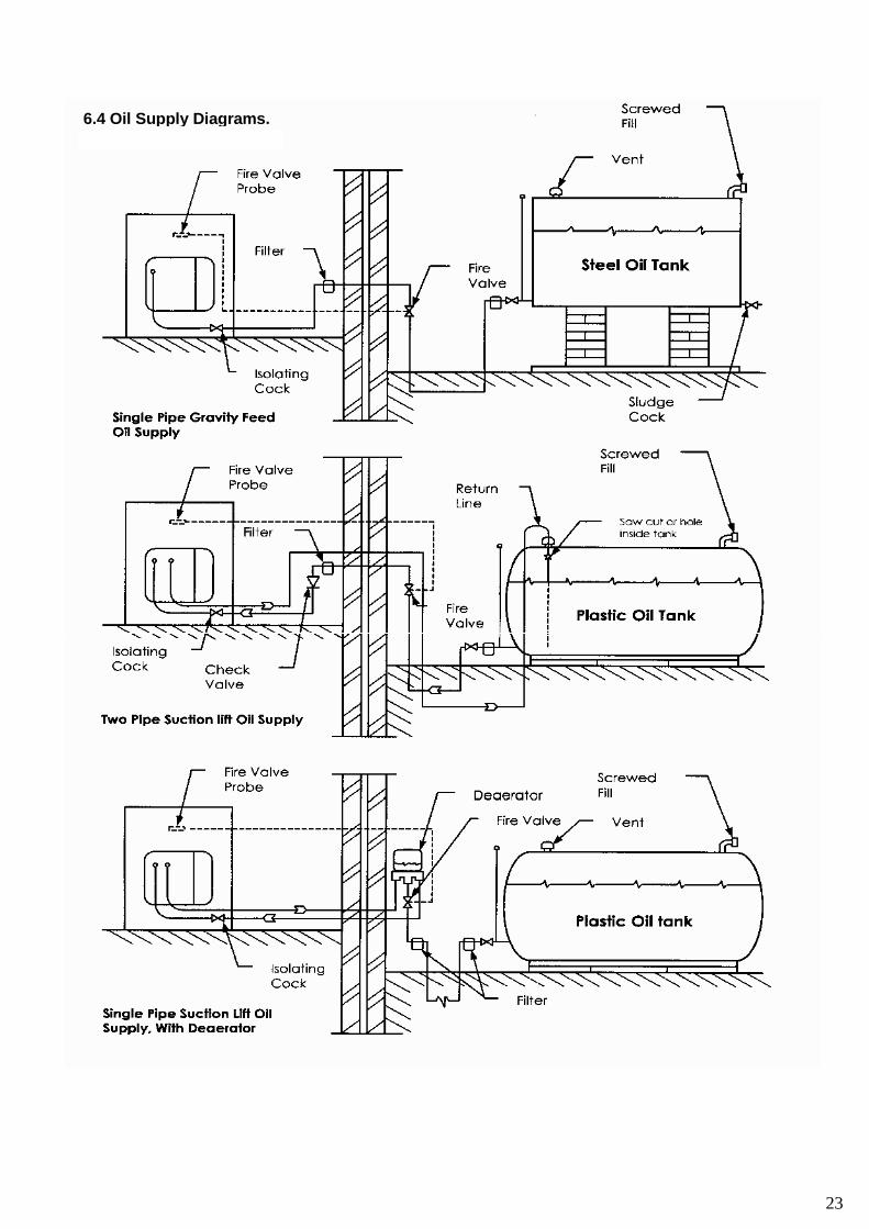
6.4 Oil Supply Diagrams.
23
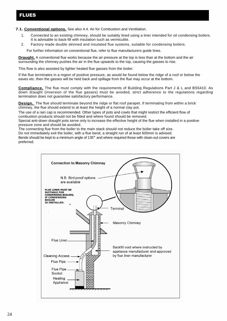
7.1. Conventional options. See also 4.4. Air for Combustion and Ventilation.
1. Connected to an existing chimney, should be suitably lined using a liner intended for oil condensing boilers.It is advisable to back-fill with insulation such as vermiculite.
2. Factory made double skinned and insulated flue systems, suitable for condensing boilers.
For further information on conventional flue, refer to flue manufacturers guide lines.
Draught. A conventional flue works because the air pressure at the top is less than at the bottom and the airsurrounding the chimney pushes the air in the flue upwards to the top, causing the gasses to rise.
This flow is also assisted by lighter heated flue gasses from the boiler.
If the flue terminates in a region of positive pressure, as would be found below the ridge of a roof or below theeaves etc. then the gasses will be held back and spillage from the flue may occur at the bottom.
Compliance. The flue must comply with the requirements of Building Regulations Part J & L and BS5410. Asdown draught (inversion of the flue gasses) must be avoided, strict adherence to the regulations regardingtermination does not guarantee satisfactory performance.
Design. The flue should terminate beyond the ridge or flat roof parapet. If terminating from within a brickchimney, the flue should extend to at least the height of a normal clay pot.
The use of a rain cap is recommended. Other types of pots and cowls that might restrict the efficient flow ofcombustion products should not be fitted and where found should be removed.Special anti-down draught pots serve only to increase the effective height of the flue when installed in a positivepressure zone and should be avoided.The connecting flue from the boiler to the main stack should not reduce the boiler take off size.Do not immediately exit the boiler, with a flue bend, a straight run of at least 600mm is advised.Bends should be kept to a minimum angle of 135° and where required those with clean-out covers arepreferred.
FLUE LINER MUST BESUITABLE FORCONDENSING BOILERS,IF CONDENSINGBOILERIS INSTALLED.
24
FLUES
Never run the flue horizontally and always try to join into the main stack either vertically or at 45°.
To make the adaptor joint: The flue should be sealed to the boiler adaptor using the appropriate hightemperature sealant.
7.2. Balanced. The range of balanced flue kits available for use with Mistral Boilers is: Low Level Horizontal rear and side outlet , f rom the same ki t. High Level Horizontal rear and side outlet, f rom the same kit. Vertical ki t for f lat/garage or pi tched roof instal lat ion.
On all balanced flues,In some cases wind can blow f lue products into the ai r intake, resul t ing in burner recycl ing, then soot.I f this happens check flue posit ion and seal ing of f lue.If f lue position or design cannot be changed, by using extensions or plume kits( see page 29-30.),suf f ic ient air must be provided from another source. The air supply to the burner can be from theroom, if enough air is available, or f i t the flexible hose to a 75mm tube to take the air f rom outside.Burner must have clean air to work.
The requirements of the building regulations and BS 5410: pt 1 must be observed. However, if there is any doubt asto the suitability of a proposed flue location, please feel free to discuss this with our technical service department.
If any part of the balanced flue terminal after installation is lower than 2m from the ground, or can be touched, or isliable to damage, then a stainless steel terminal guard is required.
Terminal positions which are likely to be in close proximity to an oil tank must comply with the requirements for oilstorage tanks in BS 5410, which is a clear distance of 1.8m and overrides the minimum dimensions for terminalpositions shown in the table unless a fire-break is built.
The dimensions shown in the table are the minimum distances advised by BS 5410. However, where experienceshows that a greater distance would be appropriate to give a more reliable installation, we have also given thegreater dimension.
Terminal positions – best practice.
The terminal should be positioned on a generally flat surface and away from recesses or projecting features(external chimney structures) as these could well cause sufficient turbulence with the air to disturb the efficientrunning of the boiler. The discharge from the terminal must be allowed to freely disperse. Where a terminal is lessthan 600mm from a plastic or combustible surface, then a heat shield is required to protect this surface.
Avoid discharging: Into a recreational area, such as a patio or play area. Onto adjoining property, unless with permission. Into a narrow passage way, particularly if it has a closed end. Into a carport. Directly into a public walkway. Directly into a below ground level space (old coal shoot)
Into an area where plants and shrubs will obviously grow and hinder the dispersal of the flue gas
Timber framed buildings are suitable for the installation of a horizontal balanced flue oil boiler. If the terminalpassing through the frame is metal sleeved and at least 50mm greater than the flue and packed with heat resistinginsulation, then each end should be capped with a metal plate for the flue to pass through and the outside sealed toprevent ingress of moisture.
The ceiling and roof timbers – vertical balanced flues. There must be no flue joints within the ceiling joist space. Joints must be at least 150mm below the ceiling. Where the flue passes through the ceiling, a means of securing the fire break must be retained. Flues which pass through habitable areas must be suitably boxed in to avoid a fire
hazard. Please refer to your local building control officer for further advice. Section J & L of the Building Regulations must be followed.
25
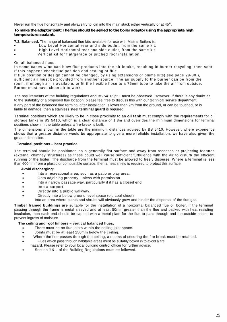
Recommended Minimum Balanced Flue Distances In (mm)
A Directly below an opening, air brick, opening windows etc. 600
B Horizontally to an opening, air brick, opening windows etc. 600
C Below a gutter or a balcony without protection. 600
D Below a gutter or a balcony with protection. 75
E From a vertically sanitary pipe work. 300
F From an internal or external corner or surface or boundary alongside terminal. 300
G Above ground or balcony level. 300
H From a surface or a boundary facing the terminal. 600
J From a terminal facing the terminal. 1200
k Vertically from a terminal on the same wall. 1500
L Horizontally from a terminal on the same wall. 750
M Above the highest point of an intersection with the roof. 600
N From a vertical structure on the side of the terminal. 750
O Above a vertical structure less than 750mm from the side of the terminal. 600
P From a ridge terminal to vertical structure on the roof. 1500
For outdoor models ensure that the factory fitted outlet isa minimum of 600mm (preferably 1000mm) away from any opening, doo r, window,and airbrick or from an overhang/gutter.
7.3 Balanced flue installation.
. The horizontal terminal
The circular flue terminal is flange mounted to the outside wall and is fixed in position with non rusting screws andwall plugs. Weather seal the reverse of the flange before securing to the wall, to stop rain penetration.
. General installation and assembly.
All balanced flue options require the removal of the conventional flue terminal adaptor, where fitted, and theretention of the sealing gasket.
The balanced flue kits fit to the same four studs with the M8 nuts and washers.Where tubes slide into each other it is important to lubricate the tube in order to protectthe rubber seal from damage during assembly.
The horizontal terminal is designed to slope slightly backwards to enable as much condensation as possible to runback into the boiler trap.
The flue tubes are telescopic and generally do not require cutting.
Low level terminals have a connection that allows the flexible air tube to connect between the flue and air entry onthe burner.
High level and vertical flues mount onto a stainless steel flue adapter that also allows the flexible air tube toconnect to the burner.
The air tube is an essential component and must be secured with the clips provided. Take care not to puncture theskin of the tube.
Due to the fact that all flue sections are fully adjustable please use the clamps provided to finish off or hold verticalsections in position prior to fitting the next vertical section.
Take care to ensure that the rubber internal flue seals do not snag whilst assembling as this will allow combustiongasses to leak and will effect the burner operation.
26
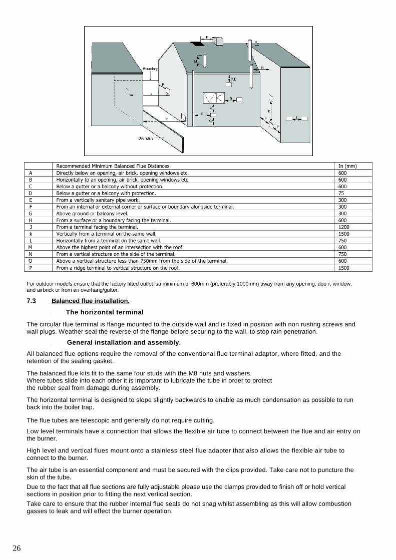
Condensing Appliance Flue Terminations
(Diagram 1.17)
(a) Terminals must not be sited under car ports. x
(b) Terminals at low level (this is terminals under 2.1 mtr havemore restrictive requirements and should not bepositioned near pub l ic foo tways and f requent l y usedaccess routes, car parking spaces less then 2.5mtrfrom the terminal or patio's (hard surface area).
x
(c) Terminals should not be positioned under a roof window. x
(d) Terminals should be positioned at least l mtr from anyside and top of a roof window.
/
(e) Terminals should be positioned at least 1 mtr away from anopening and below a gutter, eaves or balcony,
/
(f) Wall terminals should be sited a minimum of 2.5 mtrfrom any facing wall, fence, building or property boundary
/
NOTE: Locations (c) and (d) are applicable for both conventionally open fluesand vertical balanced flues.
1
1
27
The Mistral KWIC-LOC balanced flue systems have been developed to provide for both fixed andindividual flue design options. Utilizing the ‘O’ ring seal and clip fixing system, allows all parts to bequickly assembled. Manufactured from high grade stainless steel the KWIC-LOC system andaccessories are for balanced or conventional flue applications.
۞ Suitable for condensing and non condensing boilers
۞ All flue are multi directional. Low level flues are concealed within the boiler casing, improvingcosmetic appearance and helping to retain efficiency
۞ Vertical, high & low level flue kit options, available with a full range of accessories, elbows,Flashings and adapters
۞ Fixed and adjustable extensions provide for variable flue length requirements
KWIC – LOC flue is available in 2 sizes to suit boilers 15 – 41 kw and 41 – 68 kw
Part Numbers 1541 = Boilers 15 - 41 kw (50 – 140,000 btu) Flue OD Diameter 120mmPart Numbers 4168 = Boilers 41 - 68 kw (140 – 232,000 btu) Flue OD Diameter 150mm
Low Level, Vertical and High Level Kit options are supplied with the flue parts as illustrated, completewith the burner air hose & clips, seals, lubricant, boiler flue gasket, terminal guard, fixings and screws asapplicable for the kit.
Plume elbow options are available that permit low level and outdoor boiler flues to be converted into thevertical position. This allows nuisance pluming to be diverted away from windows or other obstructions.When a plume elbow is fitted, accessories from the vertical/high level flue range are used to completethe system.
Low level extensions (i.e. 1541 – HX – parts) can only be used with the low level flue system kits andthese parts are not compatible for use with vertical and high level flue systems (i.e. 1541 – X – parts).
Local conditions, flue position and the overall flue length can have an adverse and a varying effect onthe boiler performance. The boiler may require further adjustment to suit the site conditions.
For further information and advice on the Mistral KWIC – LOC flue system, please contact our technicalsales office.
28
MISTRAL KWIC-LOC FLUE SYSTEMS
29
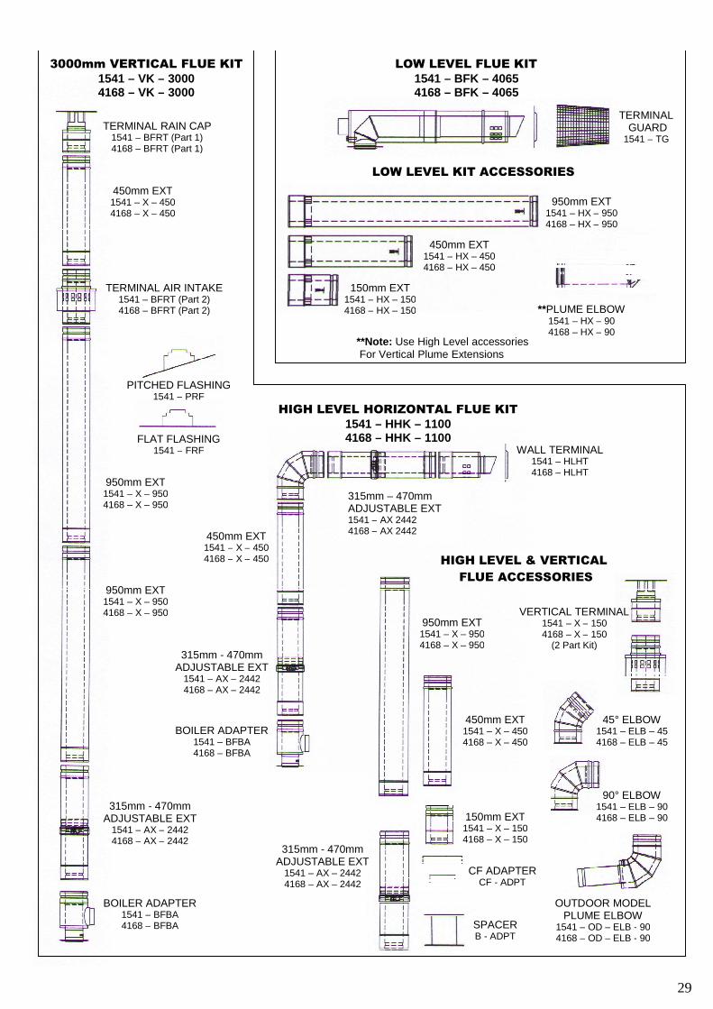
TERMINAL RAIN CAP1541 – BFRT (Part 1)4168 – BFRT (Part 1)
TERMINAL AIR INTAKE1541 – BFRT (Part 2)4168 – BFRT (Part 2)
450mm EXT1541 – X – 4504168 – X – 450
950mm EXT1541 – X – 9504168 – X – 950
950mm EXT1541 – X – 9504168 – X – 950
315mm - 470mmADJUSTABLE EXT
1541 – AX – 24424168 – AX – 2442
BOILER ADAPTER1541 – BFBA4168 – BFBA
3000mm VERTICAL FLUE KIT1541 – VK – 30004168 – VK – 3000
LOW LEVEL FLUE KIT1541 – BFK – 40654168 – BFK – 4065
LOW LEVEL KIT ACCESSORIES
150mm EXT1541 – HX – 1504168 – HX – 150
450mm EXT1541 – HX – 4504168 – HX – 450
**PLUME ELBOW1541 – HX – 904168 – HX – 90
**Note: Use High Level accessoriesFor Vertical Plume Extensions
HIGH LEVEL HORIZONTAL FLUE KIT1541 – HHK – 11004168 – HHK – 1100
450mm EXT1541 – X – 4504168 – X – 450
315mm - 470mmADJUSTABLE EXT
1541 – AX – 24424168 – AX – 2442
BOILER ADAPTER1541 – BFBA4168 – BFBA
240mm - 440mmADJUSTABLE EXT
1541 – AX – 24424168 – AX – 2442
WALL TERMINAL1541 – HLHT4168 – HLHT
950mm EXT1541 – HX – 9504168 – HX – 950
HIGH LEVEL & VERTICAL
FLUE ACCESSORIES
950mm EXT1541 – X – 9504168 – X – 950
450mm EXT1541 – X – 4504168 – X – 450
315mm - 470mmADJUSTABLE EXT
1541 – AX – 24424168 – AX – 2442
150mm EXT1541 – X – 1504168 – X – 150
SPACERB - ADPT
FLAT FLASHING1541 – FRF
PITCHED FLASHING1541 – PRF
VERTICAL TERMINAL1541 – X – 1504168 – X – 150
(2 Part Kit)
CF ADAPTERCF - ADPT
45° ELBOW1541 – ELB – 454168 – ELB – 45
90° ELBOW1541 – ELB – 904168 – ELB – 90
OUTDOOR MODELPLUME ELBOW
1541 – OD – ELB - 904168 – OD – ELB - 90
TERMINALGUARD
1541 – TG
29
315mm – 470mmADJUSTABLE EXT1541 – AX 24424168 – AX 2442
7.4 LOW LEVEL FLUE FIT UP
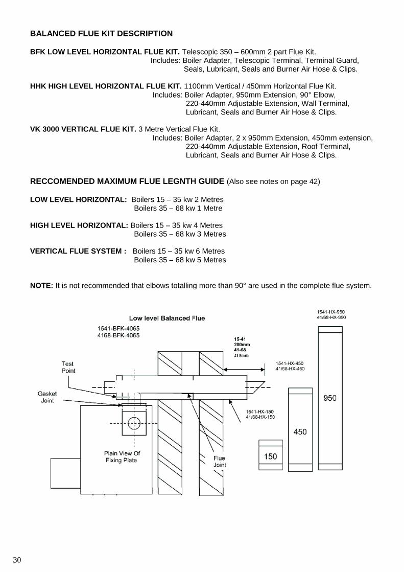
BALANCED FLUE KIT DESCRIPTION
BFK LOW LEVEL HORIZONTAL FLUE KIT. Telescopic 350 – 600mm 2 part Flue Kit.Includes: Boiler Adapter, Telescopic Terminal, Terminal Guard,
Seals, Lubricant, Seals and Burner Air Hose & Clips.
HHK HIGH LEVEL HORIZONTAL FLUE KIT. 1100mm Vertical / 450mm Horizontal Flue Kit.Includes: Boiler Adapter, 950mm Extension, 90° Elbow,
220-440mm Adjustable Extension, Wall Terminal,Lubricant, Seals and Burner Air Hose & Clips.
VK 3000 VERTICAL FLUE KIT. 3 Metre Vertical Flue Kit.Includes: Boiler Adapter, 2 x 950mm Extension, 450mm extension,
220-440mm Adjustable Extension, Roof Terminal,Lubricant, Seals and Burner Air Hose & Clips.
RECCOMENDED MAXIMUM FLUE LEGNTH GUIDE (Also see notes on page 42)
LOW LEVEL HORIZONTAL: Boilers 15 – 35 kw 2 MetresBoilers 35 – 68 kw 1 Metre
HIGH LEVEL HORIZONTAL: Boilers 15 – 35 kw 4 MetresBoilers 35 – 68 kw 3 Metres
VERTICAL FLUE SYSTEM : Boilers 15 – 35 kw 6 MetresBoilers 35 – 68 kw 5 Metres
NOTE: It is not recommended that elbows totalling more than 90° are used in the complete flue system.
30
31
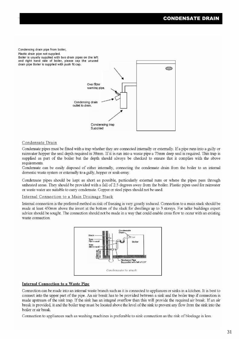
CONDENSATE DRAIN
External Connection to a Soak-away
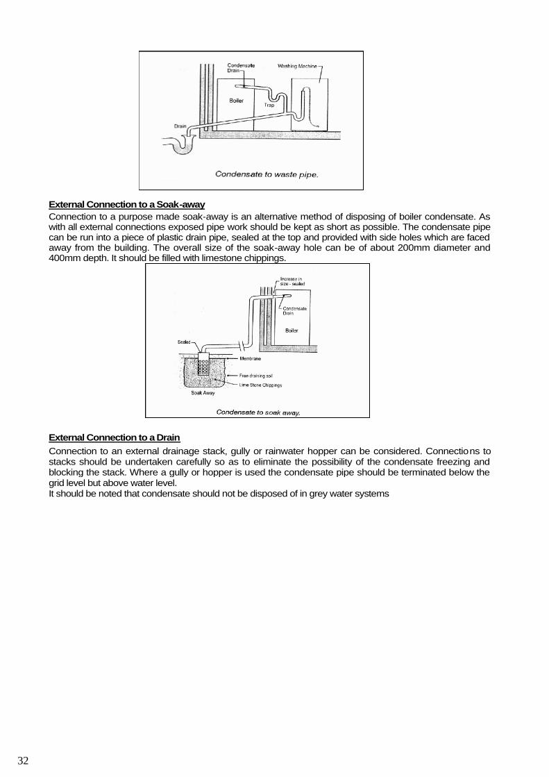
Connection to a purpose made soak-away is an alternative method of disposing of boiler condensate. Aswith all external connections exposed pipe work should be kept as short as possible. The condensate pipecan be run into a piece of plastic drain pipe, sealed at the top and provided with side holes which are facedaway from the building. The overall size of the soak-away hole can be of about 200mm diameter and400mm depth. It should be filled with limestone chippings.
External Connection to a Drain
Connection to an external drainage stack, gully or rainwater hopper can be considered. Connections tostacks should be undertaken carefully so as to eliminate the possibility of the condensate freezing andblocking the stack. Where a gully or hopper is used the condensate pipe should be terminated below thegrid level but above water level.It should be noted that condensate should not be disposed of in grey water systems
32
References BS5410: pt 1. OFTEC BOOK 2.OFTEC TI/133 Domestic oil tank, environmental risk assessment.See also Sealed Systems SECTION 5.7. System Filling and commissioning.
9.1Theboilerhas beensuppliedandtestedformidrangeof theboiler. Assiteconditionswill influencetheoperation of the boiler, these factory settings require final adjustment.
Correctly installed and set up for first firing, Mistral boilers will provide long, efficient and reliableservice.It is required that the appliance should be serviced minimum every 12 months.
Whilst every effort has been made to give the correct installation advice within this manual, thecommissioning of these boilers requires some expert knowledge.
To comply with the building regulations this boiler must be commissioned by an OFTEC or suitablyapproved engineer.
Once the boiler has been tested and your report has been compiled, it is recommended that youhighlight to the person requesting the work, any deviations and errors that may require attention. If it issafety related, please advise an appropriate course of action.
The following check list should be undertaken before the commissioning tests are undertaken. Thesequence is as outlined in the OFTEC book 2.
OFTEC form CD11 should be completed and a copy left with house holder. Please also fill in theinformation at the back of this book.
9.2 Commissioning appliance
Ensure there is no air in the heating system, and system has been flushed and treated with inhibitor. C h e c k t r a p i s p u r g e d . Remove inspection door on main heat exchanger, and condensing unit, and check baffles Remove burner and check settings / nozzle. Please refer to burner manual for correct settings. Turn elec tr ica l supply, to the boi ler ON. Set the central heating controls so they are calling for heat P u r g e a i r f r om o i l l i n e s u p p l y . Check oi l pump pressure adjus t i f required. C h e c k s m o k e r e a d i n g . Measure the Co ' and adjust air on burner accordingly. Ensure appliance is up to working temperature. Failure to do so may incur incorrect combustion settings Non condensing boilers; it is preferable for the flue gas to exceed 150 °c. If this is not the case, this can
result in more condensation entering the boiler, and in order to overcome this, it is possible to removeperhaps the top 2 baffles to obtain optimum flue gas temp.
9.3 General:It is advisable to check that the condense trap is topped up with water on a monthly basis.
There are certain parts which will require inspection and possible replacement at the time of service. Oil burner nozzle, must be replaced with the same specif ication.Never attempt to strip and clean the nozzle, as this will lead to furthe r difficulties and further expense. The oil lines must be inspected for hardening of the liner and possible leaks through the braiding. If either
condition exists, replace the hose. You are advised to replace anyway every two years.
Fuel oil filter cartridge - rinse clean, or replace with the paper element type. Clean the bowl, inspectthe bowl seal for swelling or cracks, and replace if necessary. Re-assemble taking care not to misplacethe seal.
Access door seals. The seal must be complete and provide a sound gas tight seal.Condense heat exchanger flue ways and trap is clear of any blockage.
Servicing procedure.These tasks should be undertaken by an OFTEC registered or suitably qualified engineer who is equipped with thenecessary tools and combustion testing equipment.
1. Before switching off the boiler and before starting the service, it is advisable to observe the boiler running, toget a general idea of its condition.
2. OIL STORAGE.Examine the oil supply tank and associated pipe work for signs of leakage or corrosion.Check the support piers and the fill and vent connections. Inspect the sight gauge operation and for any damage orwater ingress. For metal tanks check the plugged drain valve for water or sludge, pump out or run off asnecessary but not onto the soil.
33
COMMISSIONING / SERVICEING & MAINTENANCE
3. OIL SUPPLY.Check exposed pipe work for damage or deterioration.Examine the function of any non-return valve, fire valve (hot water test) or deaerator etc. Cleanoil filters.Inspect the flexible oil lines.
4. AIR SUPPLY.Check the combustion air and ventilation openings are clear of lint or debris.For balanced terminals see that no obstructions have been placed near the terminal and no shrubbery has grownup, which would hinder its operation. See that no additional air extraction has been added to the dwelling which couldaffect the operation of the appliance.
5. FLUES and CHIMNEYS. Inspect and clean as necessary conventional flues to the first bend. Ensure theflue has no build-up of soot or debris.
6. THE BOILER.Servicing is from the front.For Sealed System boilers, remove the expansion vessel and lay to one side. Before removing the burner, carefullydisconnect the flexible air duct, by undoing the clip at the burner air entry, turn off the oil supply cock and remove theflexible oil lines. Unplug the burner lead at the control panel and remove the burner.Undo the access covers, remove and clean all baffles, noting the order in which they were positioned. Clean the heattransfer surfaces in the boiler and vacuum out all loose debris.
Inspect the burner gasket and access cover seals and replace if necessary.
7.THE BURNER.
Remove the blast tube and clean internally and externally.Remove the electrode assembly and inspect for grazing or cracks in the ceramic. Clean and replace.Remove old nozzle and discard. Refit new nozzle of the same make, pattern and capacity as specified in the technicaldata. Brush clean the fan blades of any dust build-up.Inspect and clean the oil pumps filter. Check the condition of the photoelectric cell for signs of discolouration, cleanand replace as necessary.
8. BOILER SECURITY and COMBUSTION.Refit burner, re-connect the flexible oil line, burner lead and air hose.Attach a pressure gauge (0-20bar) air bleed manifold to correct the pump connection.After bleeding the pump of air, check the oil pressure and adjust as required.Test the combustion readings for; CO2, smoke number and flue gas temperature.Adjust the air shutter as required.Check the burner for lock-out function either by removing and covering the photoelectric cell or removing the solenoidcoil.Check the operation of the limit stat, by temporarily removing the control stat phial from its pocket. Reinstateall controls and run the boiler to confirm the operation of the control stat.
9. SEALED SYSTEM.Check the sealed system pressure and water level. REFER TO SECTION 5.7. SYSTEM FILLING ANDCOMMISSIONING.Check the operation of the pressure relief valve.
10. FINALLY. Advise the Householder of any problems.
34
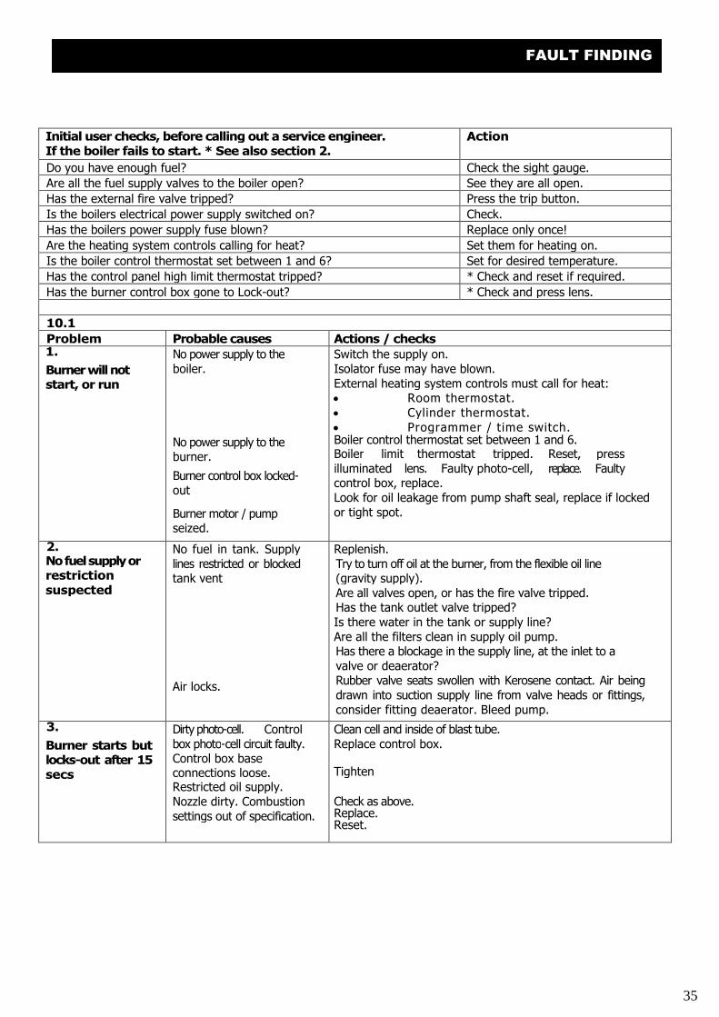
Initial user checks, before calling out a service engineer.If the boiler fails to start. * See also section 2.
Action
Do you have enough fuel? Check the sight gauge.
Are all the fuel supply valves to the boiler open? See they are all open.
Has the external fire valve tripped? Press the trip button.
Is the boilers electrical power supply switched on? Check.
Has the boilers power supply fuse blown? Replace only once!
Are the heating system controls calling for heat? Set them for heating on.
Is the boiler control thermostat set between 1 and 6? Set for desired temperature.
Has the control panel high limit thermostat tripped? * Check and reset if required.
Has the burner control box gone to Lock-out? * Check and press lens.
10.1
Problem Probable causes Actions / checks1.
Burner will notstart, or run
No power supply to theboiler.
No power supply to theburner.
Burner control box locked-out
Burner motor / pumpseized.
Switch the supply on.Isolator fuse may have blown.External heating system controls must call for heat: Room thermostat. Cylinder thermostat. Programmer / time switch.Boiler control thermostat set between 1 and 6.Boiler limit thermostat tripped. Reset, pressilluminated lens. Faulty photo-cell, replace. Faultycontrol box, replace.Look for oil leakage from pump shaft seal, replace if lockedor tight spot.
2.Nofuelsupplyorrestrictionsuspected
No fuel in tank. Supplylines restricted or blockedtank vent
Air locks.
Replenish.Try to turn off oil at the burner, from the flexible oil line(gravity supply).Are all valves open, or has the fire valve tripped.Has the tank outlet valve tripped?Is there water in the tank or supply line?Are all the filters clean in supply oil pump.Has there a blockage in the supply line, at the inlet to avalve or deaerator?Rubber valve seats swollen with Kerosene contact. Air beingdrawn into suction supply line from valve heads or fittings,consider fitting deaerator. Bleed pump.
3.
Burner starts butlocks-out after 15secs
Dirty photo-cell. Controlbox photo-cell circuit faulty.Control box baseconnections loose.Restricted oil supply.Nozzle dirty. Combustionsettings out of specification.
Clean cell and inside of blast tube.Replace control box.
Tighten
Check as above.Replace.Reset.
35
FAULT FINDING
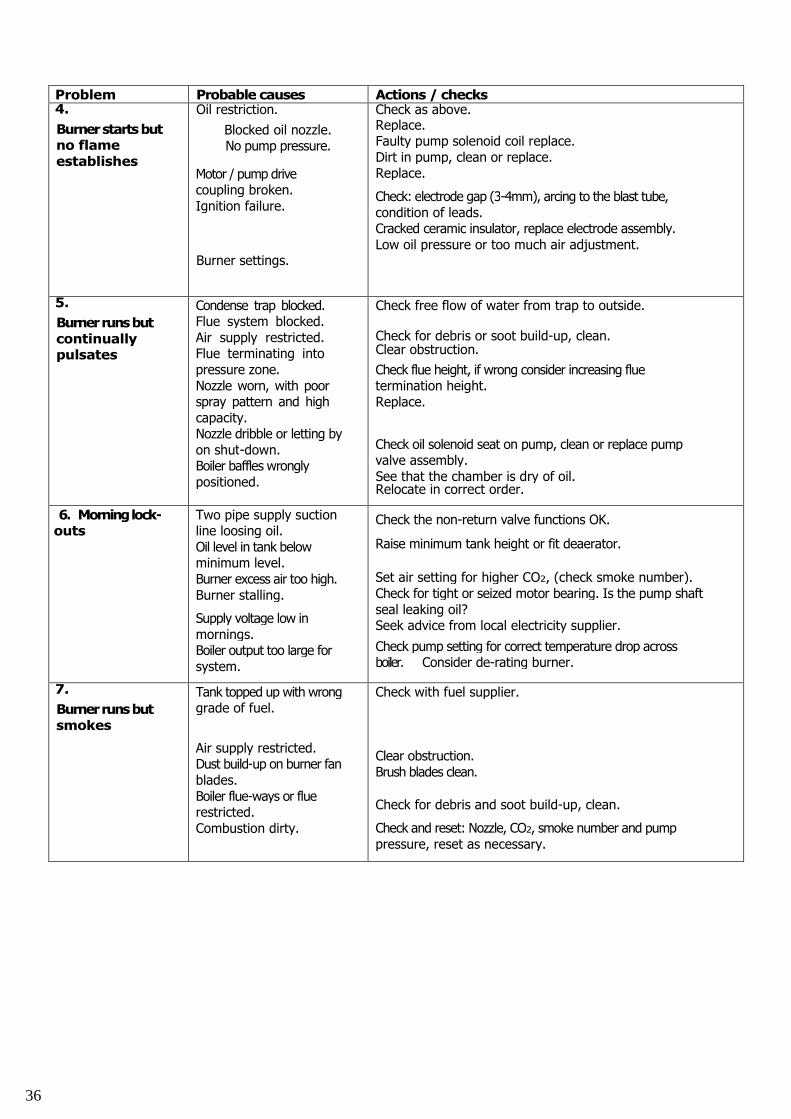
Problem Probable causes Actions / checks4.
Burnerstartsbutno flameestablishes
Oil restriction.
Blocked oil nozzle.No pump pressure.
Motor / pump drivecoupling broken.Ignition failure.
Burner settings.
Check as above.Replace.Faulty pump solenoid coil replace.Dirt in pump, clean or replace.Replace.
Check: electrode gap (3-4mm), arcing to the blast tube,condition of leads.Cracked ceramic insulator, replace electrode assembly.Low oil pressure or too much air adjustment.
5.
Burnerrunsbutcontinuallypulsates
Condense trap blocked.Flue system blocked.Air supply restricted.Flue terminating intopressure zone.Nozzle worn, with poorspray pattern and highcapacity.Nozzle dribble or letting byon shut-down.Boiler baffles wronglypositioned.
Check free flow of water from trap to outside.
Check for debris or soot build-up, clean.Clear obstruction.
Check flue height, if wrong consider increasing fluetermination height.Replace.
Check oil solenoid seat on pump, clean or replace pumpvalve assembly.See that the chamber is dry of oil.Relocate in correct order.
6. Morninglock-outs
Two pipe supply suctionline loosing oil.Oil level in tank belowminimum level.Burner excess air too high.Burner stalling.
Supply voltage low inmornings.Boiler output too large forsystem.
Check the non-return valve functions OK.
Raise minimum tank height or fit deaerator.
Set air setting for higher CO2, (check smoke number).Check for tight or seized motor bearing. Is the pump shaftseal leaking oil?Seek advice from local electricity supplier.
Check pump setting for correct temperature drop acrossboiler. Consider de-rating burner.
7.
Burnerrunsbutsmokes
Tank topped up with wronggrade of fuel.
Air supply restricted.Dust build-up on burner fanblades.Boiler flue-ways or fluerestricted.Combustion dirty.
Check with fuel supplier.
Clear obstruction.Brush blades clean.
Check for debris and soot build-up, clean.
Check and reset: Nozzle, CO2, smoke number and pumppressure, reset as necessary.
36
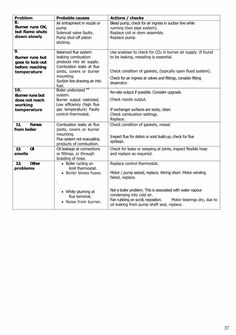
Problem Probable causes Actions / checks8.Burner runs OK,but flame shutsdown slowly
Air entrapment in nozzle orpump.Solenoid valve faulty.Pump shut-off pistonsticking.
Bleed pump, check for air ingress in suction line whilerunning (two pipe system).Replace coil or stem assembly.Replace pump.
9.
Burner runs butgoes to lock-outbefore reachingtemperature
Balanced flue systemleaking combustionproducts into air supply.Combustion leaks at fluejoints, covers or burnermounting.Suction line drawing air intofuel.
Use analyser to check for CO2 in burner air supply. If foundto be leaking, resealing is essential.
Check condition of gaskets, (typically open flued system).
Check for air ingress at valves and fittings, consider fittingdeaerator.
10.
Burner runs butdoes not reachworkingtemperature
Boiler undersized for
system.Burner output restricted.Low efficiency (high fluegas temperature) Faultycontrol thermostat.
Re-rate output if possible. Consider upgrade.
Check nozzle output.
If exchanger surfaces are sooty, clean.Check combustion settings.Replace.
11. Fumesfrom boiler
Combustion leaks at fluejoints, covers or burnermounting.Flue system not evacuatingproducts of combustion.
Check condition of gaskets, reseal.
Inspect flue for debris or soot build-up, check for fluespillage.
12. Oilsmells
Oil leakage at connectionsor fittings, or throughbraiding of hose.
Check for leaks or weeping at joints, inspect flexible hoseand replace as required.
13. Otherproblems
Boiler cycling onlimit thermostat.
Boiler blows fuses.
•
White pluming atflue terminal.
Noise from burner.
Replace control thermostat.
Motor / pump seized, replace. Wiring short. Motor windingfailed, replace.
Not a boiler problem. This is associated with water vapourcondensing into cold air.Fan rubbing on scroll, reposition. Motor bearings dry, due tooil leaking from pump shaft seal, replace.
37
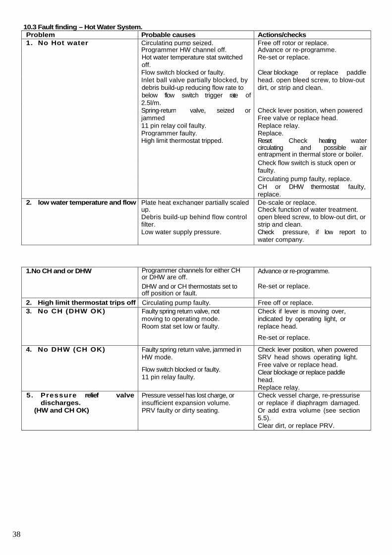
10.3 Fault finding – Hot Water System.Problem Probable causes Actions/checks1. No Hot water Circulating pump seized. Free off rotor or replace.
Programmer HW channel off. Advance or re-programme.Hot water temperature stat switchedoff.
Re-set or replace.
Flow switch blocked or faulty. Clear blockage or replace paddleInlet ball valve partially blocked, by head. open bleed screw, to blow-outdebris build-up reducing flow rate tobelow flow switch trigger rate of
dirt, or strip and clean.
2.5l/m.Spring-return valve, seized or Check lever position, when poweredjammed Free valve or replace head.11 pin relay coil faulty. Replace relay.Programmer faulty. Replace.High limit thermostat tripped. Reset. Check heating water
circulating and possible airentrapment in thermal store or boiler.
Check flow switch is stuck open orfaulty.
Circulating pump faulty, replace.CH or DHW thermostat faulty,replace.
2. low water temperature and flow Plate heat exchanger partially scaled De-scale or replace.up. Check function of water treatment.Debris build-up behind flow control open bleed screw, to blow-out dirt, orfilter. strip and clean.Low water supply pressure. Check pressure, if low report to
water company.
1.No CH and or DHW Programmer channels for either CHor DHW are off.
DHW and or CH thermostats set tooff position or fault.
Advance or re-programme.
Re-set or replace.
2. High limit thermostat trips off Circulating pump faulty. Free off or replace.
3. No CH (DHW OK) Faulty spring return valve, notmoving to operating mode.Room stat set low or faulty.
Check if lever is moving over,indicated by operating light, orreplace head.
Re-set or replace.
4. No DHW (CH OK) Faulty spring return valve, jammed inHW mode.
Flow switch blocked or faulty.11 pin relay faulty.
Check lever position, when poweredSRV head shows operating light.Free valve or replace head.Clear blockage or replace paddlehead.Replace relay.
5. Pressure relief valvedischarges.
(HW and CH OK)
Pressure vessel has lost charge, orinsufficient expansion volume.PRV faulty or dirty seating.
Check vessel charge, re-pressuriseor replace if diaphragm damaged.Or add extra volume (see section5.5).Clear dirt, or replace PRV.
38
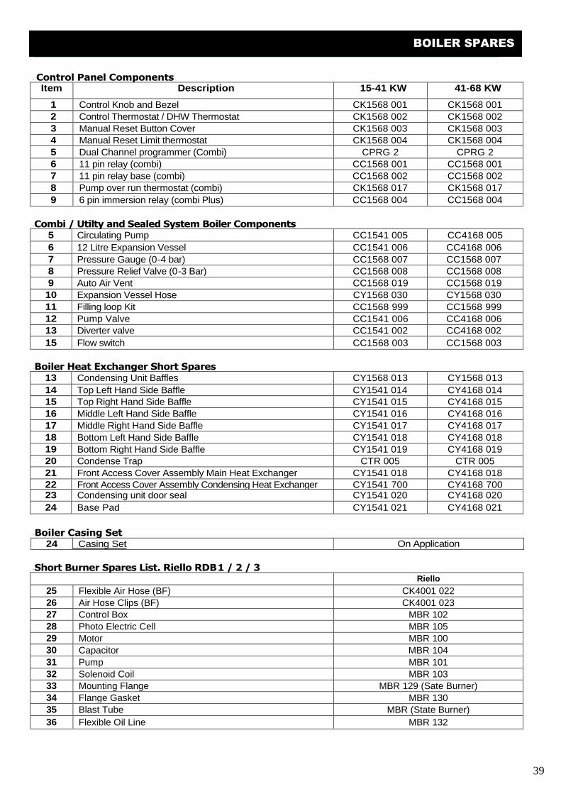
Boiler Spares 11
' Control Panel ComponentsItem Description 15-41 KW 41-68 KW
1 Control Knob and Bezel CK1568 001 CK1568 001
2 Control Thermostat / DHW Thermostat CK1568 002 CK1568 002
3 Manual Reset Button Cover CK1568 003 CK1568 0034 Manual Reset Limit thermostat CK1568 004 CK1568 004
5 Dual Channel programmer (Combi) CPRG 2 CPRG 2
6 11 pin relay (combi) CC1568 001 CC1568 001
7 11 pin relay base (combi) CC1568 002 CC1568 002
8 Pump over run thermostat (combi) CK1568 017 CK1568 017
9 6 pin immersion relay (combi Plus) CC1568 004 CC1568 004
'Combi / Utilty and Sealed System Boiler Components5 Circulating Pump CC1541 005 CC4168 005
6 12 Litre Expansion Vessel CC1541 006 CC4168 006
7 Pressure Gauge (0-4 bar) CC1568 007 CC1568 0078 Pressure Relief Valve (0-3 Bar) CC1568 008 CC1568 008
9 Auto Air Vent CC1568 019 CC1568 019
10 Expansion Vessel Hose CY1568 030 CY1568 030
11 Filling loop Kit CC1568 999 CC1568 999
12 Pump Valve CC1541 006 CC4168 00613 Diverter valve CC1541 002 CC4168 002
15 Flow switch CC1568 003 CC1568 003
'Boiler Heat Exchanger Short Spares13 Condensing Unit Baffles CY1568 013 CY1568 013
14 Top Left Hand Side Baffle CY1541 014 CY4168 01415 Top Right Hand Side Baffle CY1541 015 CY4168 015
16 Middle Left Hand Side Baffle CY1541 016 CY4168 016
17 Middle Right Hand Side Baffle CY1541 017 CY4168 017
18 Bottom Left Hand Side Baffle CY1541 018 CY4168 018
19 Bottom Right Hand Side Baffle CY1541 019 CY4168 01920 Condense Trap CTR 005 CTR 005
21 Front Access Cover Assembly Main Heat Exchanger CY1541 018 CY4168 01822 Front Access Cover Assembly Condensing Heat Exchanger CY1541 700 CY4168 70023 Condensing unit door seal CY1541 020 CY4168 020
24 Base Pad CY1541 021 CY4168 021
'Boiler Casing Set24 Casing Set On Application
'Short Burner Spares List. Riello RDB1 / 2 / 3Riello
25 Flexible Air Hose (BF) CK4001 022
26 Air Hose Clips (BF) CK4001 02327 Control Box MBR 102
28 Photo Electric Cell MBR 105
29 Motor MBR 100
30 Capacitor MBR 104
31 Pump MBR 101
32 Solenoid Coil MBR 10333 Mounting Flange MBR 129 (Sate Burner)
34 Flange Gasket MBR 130
35 Blast Tube MBR (State Burner)
36 Flexible Oil Line MBR 132
39
BOILER SPARES
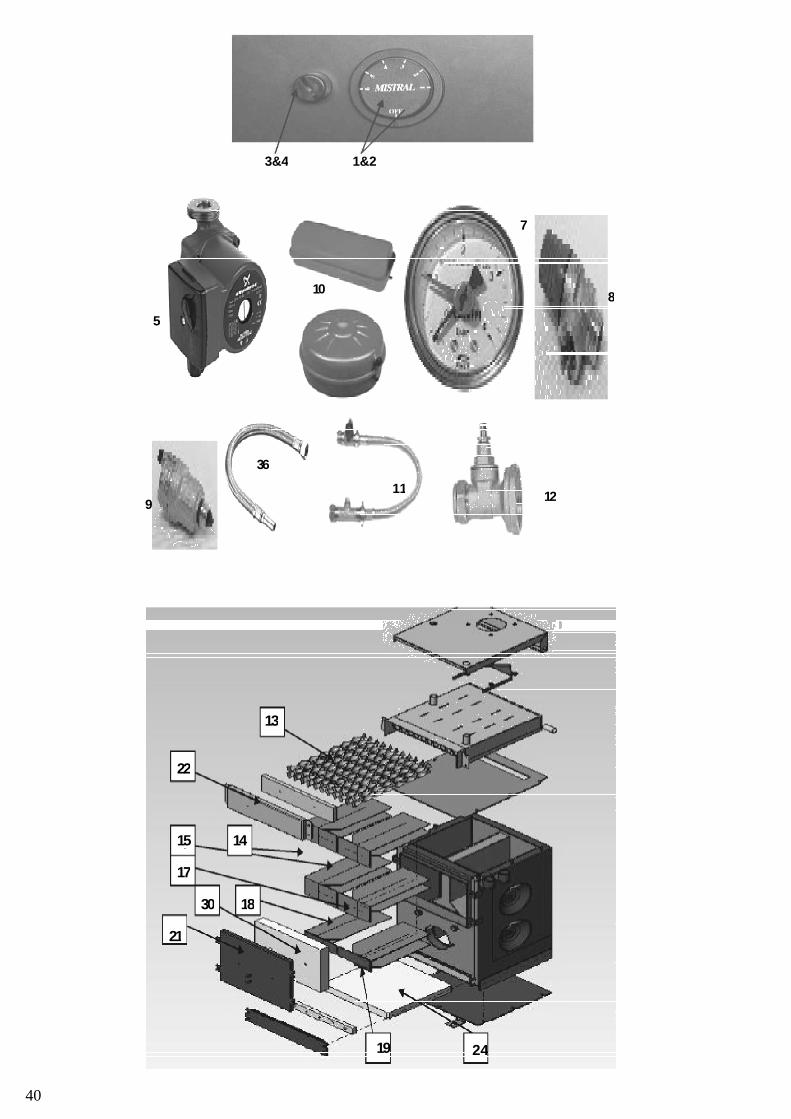
NOTES:
3&4
11
36
9
5
108
7
12
1&2
19
21
24
17
15
18
14
22
13
30
40

41
NOTES
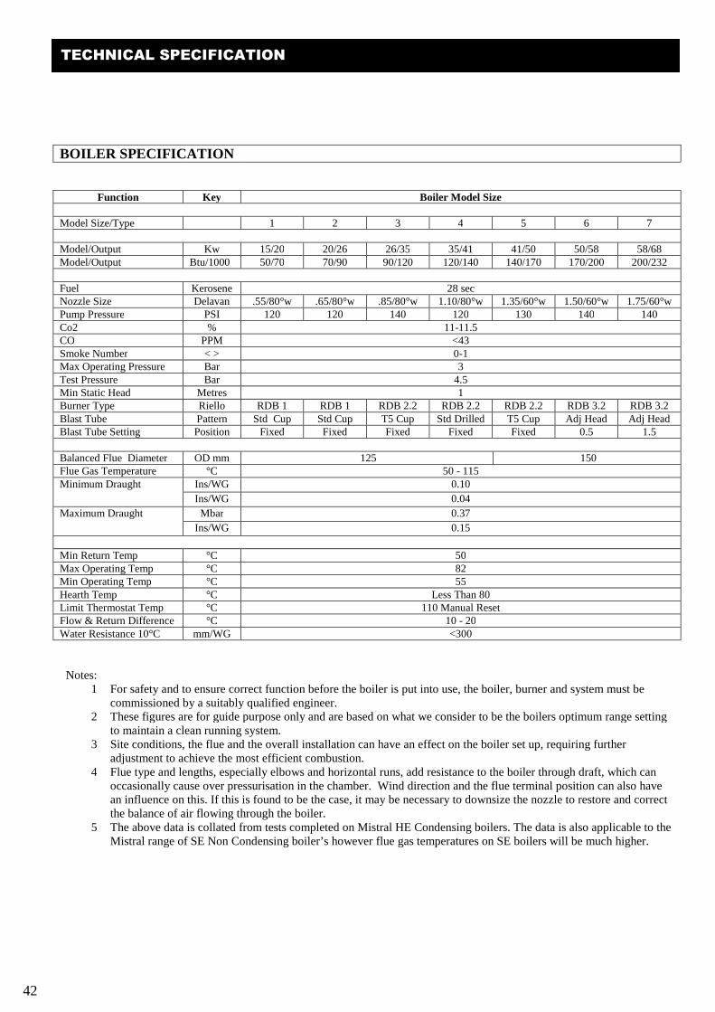
42
BOILER SPECIFICATION
Function Key Boiler Model Size
Model Size/Type 1 2 3 4 5 6 7
Model/Output Kw 15/20 20/26 26/35 35/41 41/50 50/58 58/68Model/Output Btu/1000 50/70 70/90 90/120 120/140 140/170 170/200 200/232
Fuel Kerosene 28 secNozzle Size Delavan .55/80°w .65/80°w .85/80°w 1.10/80°w 1.35/60°w 1.50/60°w 1.75/60°wPump Pressure PSI 120 120 140 120 130 140 140Co2 % 11-11.5CO PPM <43Smoke Number < > 0-1Max Operating Pressure Bar 3Test Pressure Bar 4.5Min Static Head Metres 1Burner Type Riello RDB 1 RDB 1 RDB 2.2 RDB 2.2 RDB 2.2 RDB 3.2 RDB 3.2Blast Tube Pattern Std Cup Std Cup T5 Cup Std Drilled T5 Cup Adj Head Adj HeadBlast Tube Setting Position Fixed Fixed Fixed Fixed Fixed 0.5 1.5
Balanced Flue Diameter OD mm 125 150Flue Gas Temperature °C 50 - 115Minimum Draught Ins/WG 0.10
Ins/WG 0.04
Maximum Draught Mbar 0.37
Ins/WG 0.15
Min Return Temp °C 50Max Operating Temp °C 82Min Operating Temp °C 55Hearth Temp °C Less Than 80Limit Thermostat Temp °C 110 Manual ResetFlow & Return Difference °C 10 - 20Water Resistance 10°C mm/WG <300
Notes:1 For safety and to ensure correct function before the boiler is put into use, the boiler, burner and system must be
commissioned by a suitably qualified engineer.2 These figures are for guide purpose only and are based on what we consider to be the boilers optimum range setting
to maintain a clean running system.3 Site conditions, the flue and the overall installation can have an effect on the boiler set up, requiring further
adjustment to achieve the most efficient combustion.4 Flue type and lengths, especially elbows and horizontal runs, add resistance to the boiler through draft, which can
occasionally cause over pressurisation in the chamber. Wind direction and the flue terminal position can also havean influence on this. If this is found to be the case, it may be necessary to downsize the nozzle to restore and correctthe balance of air flowing through the boiler.
5 The above data is collated from tests completed on Mistral HE Condensing boilers. The data is also applicable to theMistral range of SE Non Condensing boiler’s however flue gas temperatures on SE boilers will be much higher.
TECHNICAL SPECIFICATION
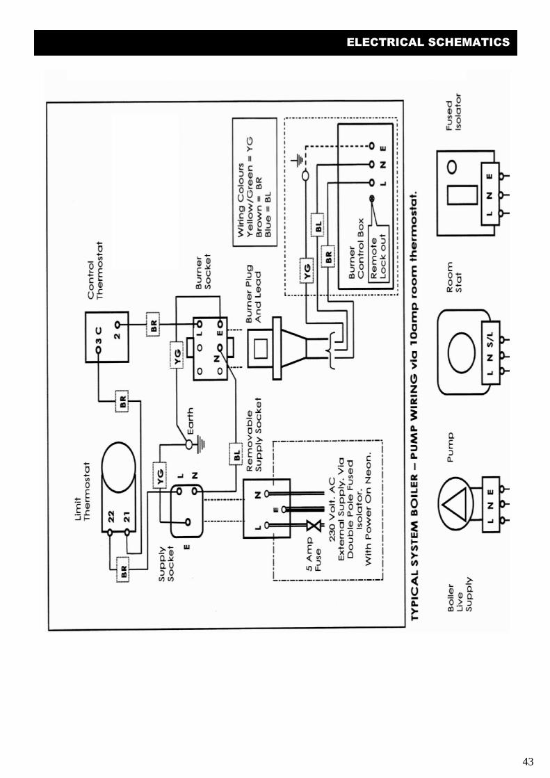
43
ELECTRICAL SCHEMATICS
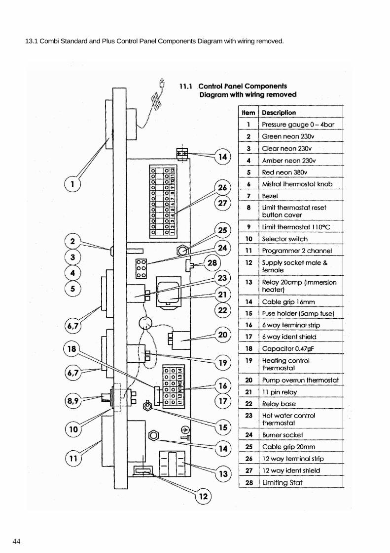
13.1 Combi Standard and Plus Control Panel Components Diagram with wiring removed.
44
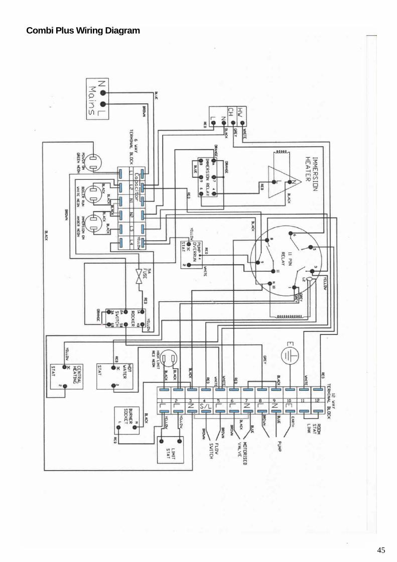
Combi Plus Wiring Diagram
45
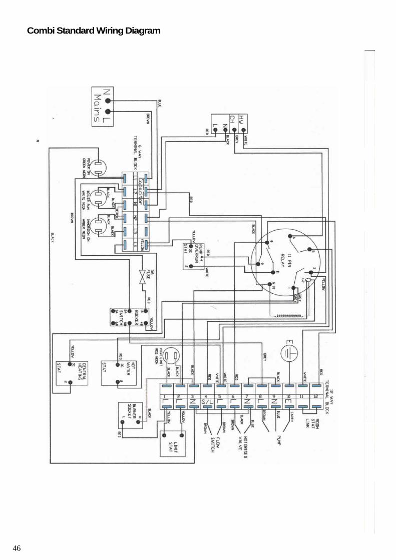
Combi Standard Wiring Diagram
46
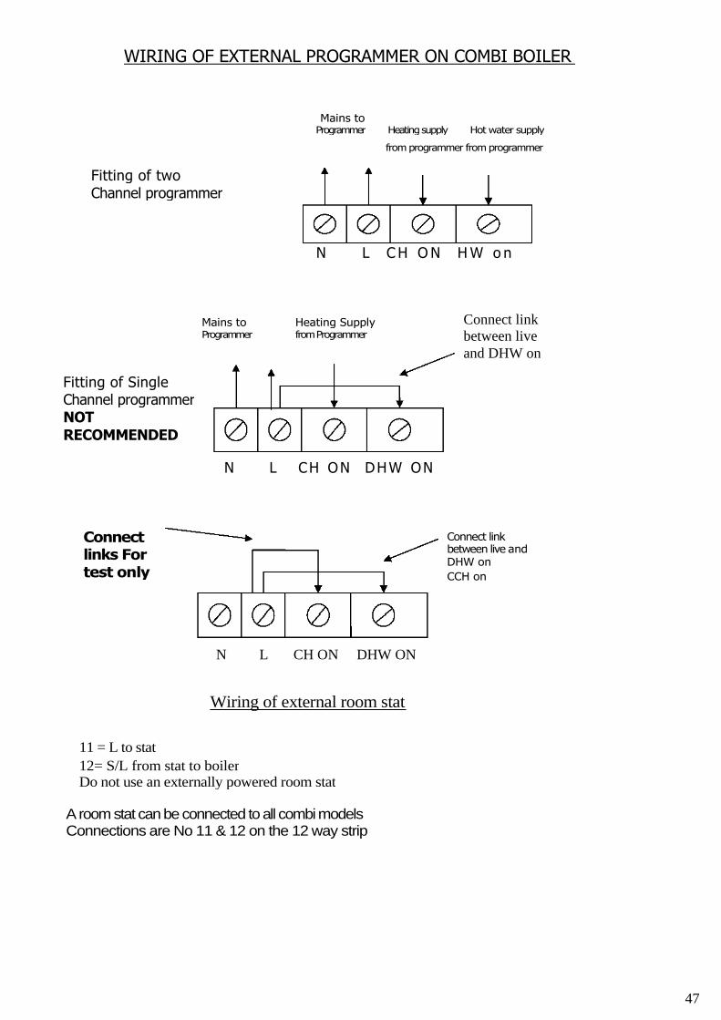
WIRING OF EXTERNAL PROGRAMMER ON COMBI BOILER
Mains toProgrammer Heatingsupply Hot water supply
from programmer from programmer
Fitting of twoChannel programmer
N L C H O N H W o n
N L CH ON DHW ON
Connectlinks Fortest only
Wiring of external room stat
11 = L to stat
12= S/L from stat to boilerDo not use an externally powered room stat
A room stat can be connected to all combimodelsConnections are No 11 & 12 on the 12 way strip
Mains toProgrammer
Connect linkbetween live andDHW on
CCH on
Heating SupplyfromProgrammer
Connect linkbetween liveand DHW on
Fitting of SingleChannel programmerNOTRECOMMENDED
N L CH ON DHW ON
47
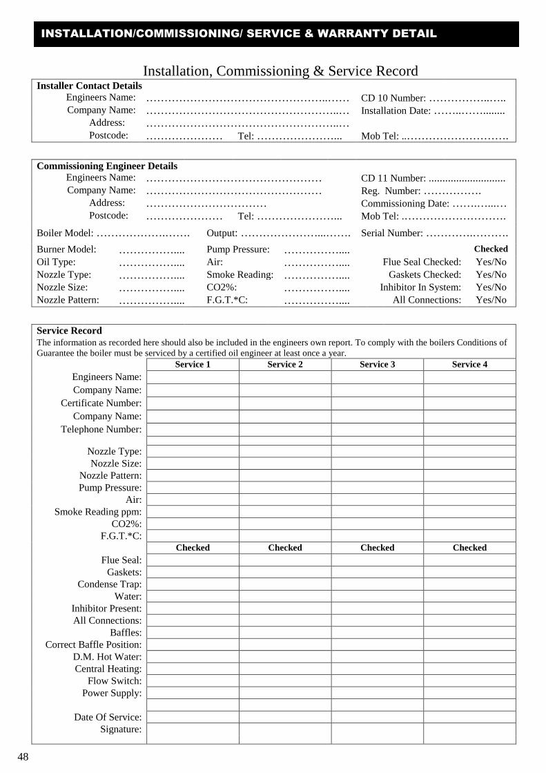
Installation, Commissioning & Service RecordInstaller Contact Details
Engineers Name: …………………………………………..…… CD 10 Number: ……………..…..Company Name: ……………………………………………..… Installation Date: ……..……........
Address: ……………………………………………..…Postcode: ………………… Tel: …………………... Mob Tel: ..……………………….
Commissioning Engineer DetailsEngineers Name: ………………………………………… CD 11 Number: ............................Company Name: ………………………………………… Reg. Number: …………….
Address: …………………………… Commissioning Date: …….…...…Postcode: ………………… Tel: …………………... Mob Tel: .……………………….
Boiler Model: ……………….……. Output: …………………...……. Serial Number: ………….……….
Burner Model: …………….... Pump Pressure: …………….... Checked
Oil Type: …………….... Air: …………….... Flue Seal Checked: Yes/No
Nozzle Type: …………….... Smoke Reading: …………….... Gaskets Checked: Yes/NoNozzle Size: …………….... CO2%: …………….... Inhibitor In System: Yes/No
Nozzle Pattern: …………….... F.G.T.*C: …………….... All Connections: Yes/No
Service RecordThe information as recorded here should also be included in the engineers own report. To comply with the boilers Conditions ofGuarantee the boiler must be serviced by a certified oil engineer at least once a year.
Service 1 Service 2 Service 3 Service 4
Engineers Name:
Company Name:
Certificate Number:
Company Name:
Telephone Number:
Nozzle Type:Nozzle Size:
Nozzle Pattern:Pump Pressure:
Air:Smoke Reading ppm:
CO2%:F.G.T.*C:
Checked Checked Checked Checked
Flue Seal:Gaskets:
Condense Trap:Water:
Inhibitor Present:All Connections:
Baffles:Correct Baffle Position:
D.M. Hot Water:Central Heating:
Flow Switch:Power Supply:
Date Of Service:Signature:
48
INSTALLATION/COMMISSIONING/ SERVICE & WARRANTY DETAIL
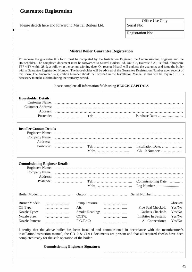
Mistral Boiler Guarantee Registration
To endorse the guarantee this form must be completed by the Installation Engineer, the Commissioning Engineer and theHouseholder. The completed document must be forwarded to Mistral Boilers Ltd. Unit C3, Halesfield 23, Telford, ShropshireTF7 4NY within 28 days following the commissioning date. On receipt Mistral will endorse the guarantee and issue the boilerwith a Guarantee Registration Number. The householder will be advised of the Guarantee Registration Number upon receipt ofthis form. The Guarantee Registration Number should be recorded in the Installation Manual as this will be required if it isnecessary to make a claim during the warranty period.
Please complete all information fields using BLOCK CAPITALS
Householder DetailsCustomer Name: ………………………………………………………………………………………
Customer Address: ………………………………………………………………………………………Address: ………………………………………………………………………………………
Postcode: ………………… Tel: ………………………... Purchase Date: …………………
Installer Contact DetailsEngineers Name: ………………………………………………………………………………………Company Name: ………………………………………………………………………………………
Address: ………………………………………………………………………………………Postcode: ………………… Tel: ………………………... Installation Date: ……..…..….
Mob:……………………... CD 10 Number: ……………..
Commissioning Engineer DetailsEngineers Name: ………………………………………………………………………………………Company Name: ………………………………………………………………………………………
Address: ………………………………………………………………………………………Postcode: ………………… Tel: ………………………... Commissioning Date: ……...…
Mob:……………………….. Reg Number: .......................
Boiler Model: ……………….……. Output: …………………...……. Serial Number: ………….……….
Burner Model: …………….... Pump Pressure: …………….... Checked
Oil Type: …………….... Air: …………….... Flue Seal Checked: Yes/No
Nozzle Type: …………….... Smoke Reading: …………….... Gaskets Checked: Yes/No
Nozzle Size: …………….... CO2%: …………….... Inhibitor In System: Yes/No
Nozzle Pattern: …………….... F.G.T.*C: …………….... All Connections: Yes/No
I certify that the above boiler has been installed and commissioned in accordance with the manufacturer’sinstallation/instruction manual, the CD10 & CD11 documents are present and that all required checks have beencompleted ready for the safe operation of the boiler.
Commissioning Engineers Signature:
……………………………………………………..
Guarantee Registration
Office Use OnlyPlease detach here and forward to Mistral Boilers Ltd. Serial No:
Registration No:
49

50
51
Mistral Boiler Guarantee1. The Mistral Terms Of Guarantee c:
d:
e:
f:
g:
h:
i:
The boiler must be maintained during the term of theguarantee. The boiler must be serviced at least onceevery 12 months by a certified oil engineer. Proof ofservicing will be required when making a warrantyclaim.Mistral will accept no liability in respect of anydefect arising from incorrect installation, misuse,negligence, fair wear & tear, repair by unqualifiedpersons or unauthorised modification.Mistral will not accept any liability for a defectoccurring in the steel heat exchanger or any otherpart caused by the build up of lime scale, lack of asuitable inhibitor, air build up, low water level orlow water return temperature.The guarantee extends to cover reasonable labourcosts specific to a repair during the 2 year period.Any additional costs incurred will be theresponsibility of the householder. In the event of adefect with the boiler steel heat exchanger outsidethe two year period, the unit must be returned at thehouseholders cost to Mistral Boilers Ltd forinspection. A repair or replacement unit will then besupplied as applicable.Prior to any warranty repair or inspection worktaking place a warranty authorisation number mustbe obtained from Mistral Boilers Ltd.Any parts removed (that are subject to a warrantyclaim), must be returned to Mistral Boilers Ltdwithin 28 days for testing and inspection.Mistral Boilers Ltd. accepts no responsibility for anyconsequential repair, loss or damage howevercaused. Any additional work required such as unitremovals, drain downs, filling or any other work thatis consequential to the repair will be the soleresponsibility of the householder.
Mistral boilers are Guaranteed (Subject to Conditions) tobe free from defective parts and workmanship from thedate of purchase for the following time periods.a: Mistral Guarantee for the period of 2 Years.
(Excluding Consumable Items) The Burner, controls,valves, pumps and all other parts used in the originalmanufacture of the boiler.
b: Mistral Guarantee for the period of 5 Years.Boiler steel heat exchanger (excluding baffles).
c: Warranty Extension. Additional and extendedboiler warranty schemes are available, details areavailable upon request.
2. Conditions Of Guaranteea: The boiler must be installed by a suitably qualified
person and the CD10 installation documentationcompleted. Prior to operation, the boiler must becommissioned by a certified oil engineer and theCD11 commissioning documentation completed. Allwork must be completed in accordance with theboiler installation manual and comply with allrelevant Standards and Codes of Practice.
b: Following the boiler commissioning, to endorse theguarantee period, the commissioning engineer mustcomplete the installation check list in the manual andthe householder must forward it to Mistral BoilersLtd within 28 days. On receipt, Mistral Boilers Ltdwill endorse the guarantee and advise thehouseholder of the guarantee registration number. Ifthe householder is not in receipt of the guaranteeregistration number within 28 days of thesubmission, Mistral Boilers Ltd must be notified ofthis fact immediately.
THE STATUTORY RIGHTS OF THE OWNER ARE NOT AFFECTED BY THIS GUARANTEE
WARRANTY BREAKDOWN PROCEDURE
In the first instance if a fault is suspected, the householder must attheir cost employ an engineer to inspect the complete heatingsystem and fuel supply.
In the unlikely event of a boiler fault, the boiler should be madesafe in all aspects. If a leak is suspected, all oil/water flow andreturn pipes to the boiler must be isolated. It is the responsibility ofthe householder/engineer to take all necessary action to make theboiler safe and ensure consequential damage limitation.
If a boiler problem is diagnosed the householder should contactMistral Boilers Ltd preferably whilst the engineer is attending.
If the problem reported is subject to a potential warranty claim itwill be necessary to provide details of the following:
1. Boiler Model Type & Serial Number2. Date Of Purchase (Copy Of Sales Invoice)3. CD10 Installation Number4. CD11 Commissioning Number5. Mistral Guarantee Number6. Service History Log
If the claim is accepted by Mistral Boilers Ltd as a potentialwarranty issue, a works authorisation number will be issued for aspecific repair to be completed either by the attending engineer oran appointed Mistral Technician in the area.
Prior to the commencement of any work, Mistral BoilersLtd will require the authority and acceptance from thehouseholder/engineer that all or any work completed willbe chargeable in full if a fault is found not to beacceptable as a warranty claim.
Parts removed that are the subject of a warranty claimmust be returned with the warranty claim invoice.
Mistral will not accept any invoice or charge forunauthorised or non acceptable warranty work. Any othercosts will be the sole responsibility of thehouseholder/engineer.
BOILER INFORMATION
Please record the following information.
Model Type …………………………………………..
Serial Number………………………………………...
Date Of Purchase…………………………………......
CD10 Number…………………………………...……
CD11 Number……………………………………..…
Mistral Guarantee Number……………………….….
NOTE: Mistral Boilers Limited will accept no claims for a warranty repair unless a full payment for the product or any prior workcompleted on the product has been received in full and in accordance to Mistral Boilers Limited Terms & Conditions of sale.
51
Tel: 01952 270082 Fax: 01952 270086
Web: - mistralboilers.com email: - [email protected]
Mistral Boilers Ltd, Unit D4, Halesfield 23,Telford, Shropshire, TF7 4NY
Mistral Boilers maintain a policy of continuous improvement and in order to stay at the forefront of boiler technology reserves the right to alter specificationswithout notice. The statutory rights of the customer are not affected. All information correct at time of going to press.
All our manufacturing is carried outunder a stringent quality control systemto BS5750 ISO9002 and monitored by the
British Standards Institute.
With high efficiency and low emissionsthe Mistral range of oil fired boilers areenvironmentally friendly and as a result
economical to run.
Complies with the EC low voltage and
electromagnetic compatibility
and efficiency directives.
OIL FIRINGTECHNICAL
ASSOCIATION FORTHEPETROLEUMINDUSTRY
OIL FIRING EQUIPMENTG RO UPMEMBER
Registered equipment group member of
the oil firing technical association for
the petroleum industry.
All of our products are manufactured at our Telford facility which covers in excess of 25,000 sq ft.We utilise some of the most advanced computer controlled machinery including point to point
penetration robotic welding cells to manufacture our products to exacting standards.
Mistral Boilers have been a privately owned company since the early 1960’s and are one of thelongest standing British Manufacturers of Oil Fired Boilers & associated components.
We are proud of our products and should you require any advice orguidance please feel free to contact us on the number below.