Embed Size (px)
Citation preview

This manual must be used in conjunction with the Installation Manual before, and during installation!
Owner's Manual8 - 20kW Air-cooled,Automatic Standby Generators
NOT INTENDED FOR USE IN CRITICAL LIFE SUPPORT APPLICATIONS.
ONLY QUALIFIED ELECTRICIANS OR CONTRACTORS SHOULD ATTEMPT INSTALLATION!
DEADLY EXHAUST FUMES! OUTDOOR INSTALLATION ONLY!
www.generac.com or 1-888-GENERAC
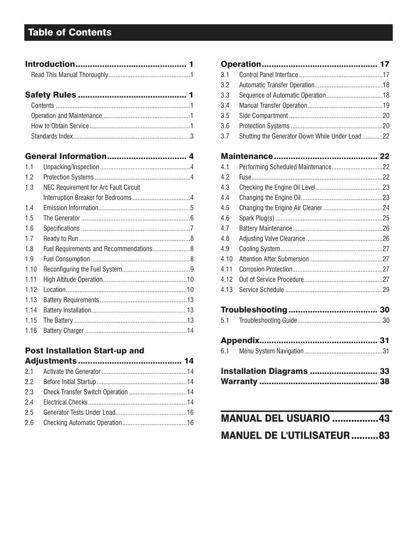
Introduction .............................................. 1 Read This Manual Thoroughly ................................................1
Safety Rules ............................................. 1 Contents ...............................................................................1
Operation and Maintenance....................................................1
How to Obtain Service ...........................................................1
Standards Index .....................................................................3
General Information ................................. 41.1 Unpacking/Inspection .....................................................4
1.2 Protection Systems ........................................................4
1.3 NEC Requirement for Arc Fault Circuit
Interruption Breaker for Bedrooms ..................................4
1.4 Emission Information......................................................5
1.5 The Generator ................................................................6
1.6 Specifications ................................................................7
1.7 Ready to Run .................................................................8
1.8 Fuel Requirements and Recommendations ......................8
1.9 Fuel Consumption ..........................................................8
1.10 Reconfiguring the Fuel System ........................................9
1.11 High Altitude Operation .................................................10
1.12 Location .......................................................................10
1.13 Battery Requirements ...................................................13
1.14 Battery Installation ........................................................13
1.15 The Battery ..................................................................13
1.16 Battery Charger ............................................................14
Post Installation Start-up and Adjustments ........................................... 142.1 Activate the Generator ..................................................14
2.2 Before Initial Startup .....................................................14
2.3 Check Transfer Switch Operation ..................................14
2.4 Electrical Checks ..........................................................14
2.5 Generator Tests Under Load ..........................................16
2.6 Checking Automatic Operation ......................................16
Operation ................................................ 173.1 Control Panel Interface .................................................17
3.2 Automatic Transfer Operation ........................................18
3.3 Sequence of Automatic Operation .................................18
3.4 Manual Transfer Operation ............................................19
3.5 Side Compartment .......................................................20
3.6 Protection Systems ......................................................20
3.7 Shutting the Generator Down While Under Load ............22
Maintenance ........................................... 224.1 Performing Scheduled Maintenance ..............................22
4.2 Fuse .............................................................................22
4.3 Checking the Engine Oil Level .......................................23
4.4 Changing the Engine Oil ................................................23
4.5 Changing the Engine Air Cleaner ...................................24
4.6 Spark Plug(s) ...............................................................25
4.7 Battery Maintenance .....................................................26
4.8 Adjusting Valve Clearance .............................................26
4.9 Cooling System ............................................................27
4.10 Attention After Submersion ...........................................27
4.11 Corrosion Protection.....................................................27
4.12 Out of Service Procedure ..............................................27
4.13 Service Schedule .........................................................29
Troubleshooting ..................................... 305.1 Troubleshooting Guide ..................................................30
Appendix................................................. 316.1 Menu System Navigation ..............................................31
Installation Diagrams ............................ 33Warranty ................................................. 38
Table of Contents
1
Thank you for purchasing this compact, high performance, air-cooled, engine-driven generator. It is designed to automatically supply electrical power to operate critical loads during a utility power failure.
This unit is factory installed in an all-weather, metal enclosure and is intended exclusively for outdoor installation. This generator will operate using either vapor withdrawn liquid propane (LP) or natural gas (NG).
NOTE:
This generator is suitable for supplying typical residential loads such as Induction Motors (sump pumps, refrigerators, air conditioners, furnaces, etc.), Electronic Components (computer, monitor, TV, etc.), Lighting Loads and Microwaves.
If any portion of this manual is not understood, contact the nearest Dealer for starting, operating and servicing procedures. SAVE this Manual. Provide this manual to any operator of the generator.
Throughout this publication, and on tags and decals affixed to the genera-tor, DANGER, WARNING, CAUTION and NOTE blocks are used to alert personnel to special instructions about a particular operation that may be hazardous if performed incorrectly or carelessly. Observe them carefully. Their definitions are as follows:
INDICATES A HAZARDOUS SITUATION OR ACTION WHICH, IF NOT AVOIDED, WILL RESULT IN DEATH OR SERIOUS INJURY.
Indicates a hazardous situation or action which, if not avoided, could result in death or serious injury.
Indicates a hazardous situation or action which, if not avoided, could result in minor or moderate injury.
NOTE:
Notes contain additional information important to a procedure and will be found within the regular text body of this manual.
These safety warnings cannot eliminate the hazards that they indicate. Common sense and strict compliance with the special instructions while performing the action or service are essential to preventing accidents.
Four commonly used safety symbols accompany the DANGER, WARNING and CAUTION blocks. The type of information each indicates is as follows:
This symbol points out important safety information that, if not followed, could endanger personal safety and/or property of others.
This symbol points out potential explosion hazard.
This symbol points out potential fire hazard.
This symbol points out potential electrical shock hazard.
The operator is responsible for proper and safe use of the equipment. The manufacturer strongly recommends that the operator read this Owner's Manual and thoroughly understand all instructions before using this equipment. The manufacturer also strongly recommends instructing other users to properly start and operate the unit. This prepares them if they need to operate the equipment in an emergency.
This manual contains pertinent owner’s information for these models:• 7 kW NG, 8 kW LP, single-cylinder GH-410 Engine• 9 kW NG, 10 kW LP, V-twin GT-530 Engine• 13 kW NG, 13 kW LP, V-twin GT-990 Engine• 13 kW NG, 14 kW LP, V-twin GT-990 Engine• 16 kW NG, 16 kW LP, V-twin GT-990 Engine• 16 kW NG, 17 kW LP, V-twin GT-990 Engine• 18 kW NG, 20 kW LP, V-twin GT-999 Engine
It is the operator's responsibility to perform all safety checks, to make sure that all maintenance for safe operation is performed promptly, and to have the equipment checked periodically by a Dealer. Normal maintenance ser-vice and replacement of parts are the responsibility of the owner/operator and, as such, are not considered defects in materials or workmanship within the terms of the warranty. Individual operating habits and usage contribute to the need for maintenance service.
Proper maintenance and care of the generator ensures a minimum number of problems and keep operating expenses at a minimum. See a Dealer for service aids and accessories.
When the generator requires servicing or repairs, contact a Dealer for assistance. Service technicians are factory-trained and are capable of handling all service needs.
When contacting a Dealer about parts and service, always supply the complete model number and serial number of the unit as given on its data decal, which is located on the generator. See section "The Generator" for decal location.
Model No. _________________ Serial No. ______________
Safety Rules
2
Study these SAFETY RULES carefully before installing, operating or servicing this equipment. Become familiar with this Owner�s Manual and with the unit. The generator can operate safely, effi-ciently and reliably only if it is properly installed, operated and maintained. Many accidents are caused by failing to follow simple and fundamental rules or precautions.
The manufacturer cannot anticipate every possible circumstance that might involve a hazard. The warnings in this manual, and on tags and decals affixed to the unit are, therefore, not all-inclusive. If using a procedure, work method or operating technique the manu-facturer does not specifically recommend, ensure that it is safe for others. Also make sure the procedure, work method or operating technique utilized does not render the generator unsafe.
Despite the safe design of this generator, operating this equipment imprudently, neglect-ing its maintenance or being careless can cause possible injury or death. Permit only responsible and capable persons to install, operate and maintain this equipment.
Potentially lethal voltages are generated by these machines. Ensure all steps are taken to render the machine safe before attempting to work on the generator.
Parts of the generator are rotating and/or hot during operation. Exercise care near run-ning generators.
Installation must always comply with appli-cable codes, standards, laws and regula-tions.
A running generator gives off carbon mon-oxide, and odorless, colorless poison gas. Breathing in carbon monoxide can cause headaches, fatigue, diziness, nausea, vomit-ting, confusion, fainting, siezures or death.
GENERAL HAZARDS
• The engine exhaust fumes contain carbon monoxide, which can be DEADLY. This dangerous gas, if breathed in sufficient concentrations, can cause unconsciousness or even death. Do NOT alter or add to the exhaust system or do anything that might render the system unsafe or in noncompliance with appli-cable codes and standards.
• Install a battery operated carbon monoxide alarm indoors, according to manufacturer's instructions/recommendations.
• Adequate, unobstructed flow of cooling and ventilating air is critical to correct generator operation. Do not alter the instal-lation or permit even partial blockage of ventilation provisions, as this can seriously affect safe operation of the generator. The generator MUST be installed and operated outdoors only.
• Keep hands, feet, clothing, etc., away from drive belts, fans, and other moving or hot parts. Never remove any drive belt or fan guard while the unit is operating.
• When working on this equipment, remain alert at all times. Never work on the equipment when physically or mentally fatigued.
• Inspect the generator regularly, and contact the nearest Dealer for parts needing repair or replacement.
• Before performing any maintenance on the generator, discon-nect its battery cables to prevent accidental start up. Disconnect the cable from the battery post indicated by a NEGATIVE, NEG or (–) first, then remove the POSITIVE, POS or (+) cable. When reconnecting the cables, connect the POSITIVE cable first, the NEGATIVE cable last.
• Never use the generator or any of its parts as a step. Stepping on the unit can stress and break parts, and may result in dan-gerous operating conditions from leaking exhaust gases, fuel leakage, oil leakage, etc.
EXHAUST HAZARDS• Generator engine exhaust contains DEADLY carbon monox-
ide, an odorless, colorless poisonous gas. Breathing carbon monoxide can cause: dizziness, throbbing temples, nausea, muscular twitching, headache, vomiting, weakness and sleepi-ness, inability to think clearly, fainting, unconsciousness or even death. If you experience any carbon monoxide poisoning symptoms, move into fresh air and immediately seek medical attention.
• NEVER operate the generator set inside any garage or other enclosed area EVEN IF the doors and windows are open.
ELECTRICAL HAZARDS
• All generators covered by this manual produce dangerous elec-trical voltages and can cause fatal electrical shock. Utility power delivers extremely high and dangerous voltages to the transfer switch as does the standby generator when it is in operation. Avoid contact with bare wires, terminals, connections, etc., while the unit is running. Ensure all appropriate covers, guards and barriers are in place, secured and/or locked before operat-ing the generator. If work must be done around an operating unit, stand on an insulated, dry surface to reduce shock hazard.
• DO NOT handle any kind of electrical device while stand-ing in water, while barefoot, or while hands or feet are wet. DANGEROUS ELECTRICAL SHOCK MAY RESULT.
SAVE THESE INSTRUCTIONS � The manufacturer suggests that these rules for safe operation be copied and posted near the unit�s installation site. Safety should be stressed to all operators and potential operators of this equipment.
Safety Rules
3
• The National Electrical Code (NEC) requires the frame and external electrically conductive parts of the generator to be connected to an approved earth ground. Local electrical codes also may require proper grounding of the generator electrical system.
• After installing this home standby electrical system, the genera-tor may crank and star t at any time without warning. When this occurs, load circuits are transferred to the STANDBY (genera-tor) power source. To prevent possible injury if such a start and transfer occur, always set the generator’s AUTO/OFF/MANUAL switch to its OFF position before working on equipment and remove the 7.5A fuse from the generator control panel.
• In case of accident caused by electric shock, immediately shut down the source of electrical power. If this is not possible, attempt to free the victim from the live conductor. AVOID DIRECT CONTACT WITH THE VICTIM. Use a nonconducting implement, such as a dry rope or board, to free the victim from the live conductor. If the victim is unconscious, apply first aid and get immediate medical help.
• Never wear jewelry when working on this equipment. Jewelry can conduct electricity resulting in electric shock, or may get caught in moving components causing injury.
FIRE HAZARDS• For fire safety, the generator must be installed and maintained
properly. Installation must always comply with applicable codes, standards, laws and regulations. Adhere strictly to local, state and national electrical and building codes. Comply with regulations the Occupational Safety and Health Administration (OSHA) has established. Also, ensure that the generator is installed in accordance with the manufacturer’s instructions and recommendations. Following proper installa-tion, do nothing that might alter a safe installation and render the unit in noncompliance with the aforementioned codes, standards, laws and regulations.
• Keep a fire extinguisher near the generator at all times. Extinguishers rated “ABC” by the National Fire Protection Association are appropriate for use on the standby electric system. Keep the extinguisher properly charged and be familiar with its use. Consult the local fire depar tment with any ques-tions pertaining to fire extinguishers.
EXPLOSION HAZARDS
• Do not smoke around the generator. Wipe up any fuel or oil spills immediately. Ensure that no combustible materials are left in the generator compartment, or on or near the generator, as FIRE or EXPLOSION may result. Keep the area surrounding the generator clean and free from debris.
• Gaseous fluids such as natural gas and liquid propane (LP) gas are extremely EXPLOSIVE. Install the fuel supply system according to applicable fuel-gas codes. Before placing the home standby electric system into service, fuel system lines must be properly purged and leak tested according to applica-ble code. After installation, inspect the fuel system periodically for leaks. No leakage is permitted.
Applicable national, state, or local laws, codes, and regulations pertaining to the installation of engine-generator power systems must be strictly complied with. Always use the current accept-able version or edition of the applicable code or standard which applies to your jurisdiction. In the absence of pertinent local laws and standards, the following published booklets may be used as a guide (these apply to localities which recognize NFPA and IBC):
1. National Fire Protection Association (NFPA) 70: The NATIONAL ELECTRIC CODE (NEC) *
2. NFPA 10: Standard for Portable Fire Extinguishers *3. NFPA 30: Flammable And Combustible Liquids Code *4. NFPA 37: Standard for Stationary Combustion Engines And
Gas Turbines *5. NFPA 54: National Fuel Gas Code *6. NFPA 58: Standard for Storage And Handling Of Liquefied
Petroleum Gases *7. NFPA 70E: Standard For Electrical Safety In The Workplace *8. NFPA 5000: Building Code *9. ASAE EP-364.2 Installation and Maintenance of Farm Standby
Electric Power ****10. Agricultural Wiring Handbook ***11. International Building Code **
This list is not all inclusive. Check with the Authority Having Local Jurisdiction (AHJ) for any local codes or standards which may be applicable to your jurisdiction. The above listed standards are available from the following internet sources:
* www.nfpa.org
** www.iccsafe.org
*** www.rerc.org Rural Electricity Resource Council, P.O. Box 309 Wilmington, OH 45177-0309
**** www.asabe.org American Society of Agricultural & Biological Engineers, 2950 Niles Road, St. Joseph, MI 49085
CALIFORNIA PROPOSITION 65 WARNINGEngine exhaust and some of its constituents are known to the State of California to cause cancer, birth defects
and other reproductive harm.
CALIFORNIA PROPOSITION 65 WARNINGThis product contains or emits chemicals known to the State of California to cause cancer, bir th defects and
other reproductive harm.
Safety Rules
Only qualified electricians or contractors should attempt such installations, which must comply strictly with applicable codes, stan-dards and regulations.
After unpacking, carefully inspect the contents for damage.
• This standby generator set is ready for installation with a factory supplied and pre-mounted base pad and has a weather protec-tive enclosure that is intended for outdoor installation only.
• This UL listed standby generator set may be packaged with an automatic transfer switch with built in load center. The combi-nation transfer switch and load center is pre-wired with a two foot and 30 foot conduit. Circuit breakers for emergency circuit connections are included (if equipped).
• This UL listed, 2-pole switch is rated at 100 or 200 AC amperes at 250 volts maximum. The 100 Amp transfer switch is for indoor use only. The 200 Amp transfer switch is for indoor/outdoor use (if equipped).
If this generator is used to power electrical load circuits normally powered by a utility power source, it is required by code to install a trans-fer switch. The transfer switch must effectively isolate the electrical system from the utility distribution system when the generator is oper-ating (NEC 700, 701 & 702). Failure to isolate an electrical system by such means will result in damage to the generator and also may result in injury or death to utility power workers due to backfeed of electrical energy.
If any loss or damage is noted at time of delivery, have the person(s) making the delivery note all damage on the freight bill or affix their signature under the consignor's memo of loss or damage.
If a loss or damage is noted after delivery, separate the damaged materials and contact the carrier for claim procedures.
“Concealed damage” is understood to mean damage to the con-tents of a package that is not in evidence at the time of delivery, but is discovered later.
To properly open the roof, press down on the center top lip and release the latch. If pressure is not applied from the top, the roof may appear stuck. Always verify that the side lock is unlocked before attempting to lift the roof.
Unlike an automobile engine, the generator may have to run for long periods of time with no operator present to monitor engine conditions. For that reason, the engine is equipped with the fol-lowing systems that protect it against potentially damaging condi-tions:
1. Low Oil Pressure Sensor 6. Low Battery2. High Temperature Sensor 7. Under-frequency3. Overcrank 8. Undervoltage4. Overspeed 9. Overvoltage5. RPM Sensor 10. Internal FailureThere are readouts on the control panel to notify personnel that one of these failures has occurred. There is a Status message on the display that displays when all of the conditions described in the "Ready to Run" section are true.
In 2001, the National Electric Code (NEC) introduced a requirement for new construction. This new requirement indicates the need for Arc Fault Circuit Interrupters to be used to protect the complete branch circuit that feeds a dwelling bedroom. The actual NEC requirement is indicated below.
1. Definition: An arc fault circuit interrupter is a device intended to provide protection from the effects of arc faults by recog-nizing characteristics unique to arcing and by functioning to de-energize the circuit when an arc fault is detected.
2. Dwelling Unit Bedrooms: All branch circuits that supply 125 volt, single-phase, 15 and 20 ampere outlets installed in dwelling unit bedrooms shall be protected by an arc fault cir-cuit interrupter listed to provide protection of the entire branch circuit.
Section 210.12 requires that AFCI protection be provided on branch circuits that supply outlets (receptacle, lighting, etc.) in dwell-ing bedrooms. The requirement is limited to 15 and 20 ampere, 125 volt circuits. There is no prohibition against providing AFCI protection on other circuits or in locations other than bedrooms. Because circuits are often shared between a bedroom and other areas such as closets and hallways, providing AFCI protection on the complete circuit would comply with 210.12.
4
General Information
5
If during the installation of the home standby system the decision is made to provide back up power to a bedroom branch circuit, then the circuit breaker in the transfer switch should be replaced with an Arc Fault Circuit Interrupter.
It is most important that breakers only be switched like for like. For instance, if replacing a 15A breaker, it MUST be replaced with a 15A AFCI breaker. Likewise, a 20A breaker MUST be replaced with a 20A AFCI.
These AFCI breakers are available at the nearest hardware store.
Item # Description
Q115AF 15A Single Pole AFCI
Q120AF 20A Single Pole AFCI
The U.S. Environmental Protection Agency (EPA) requires that this generator comply with exhaust emission standards. This generator is certified to meet the applicable EPA emission levels, and is certified for use as a stationary engine for standby power generation. Any other use may be a violation of federal and/or local laws. It is important to follow the maintenance specifications in the Maintenance section to ensure that the engine complies with the applicable emission standards for the duration of the engine’s life. This generator is certified to operate on Liquid Propane Vapor fuel and pipeline Natural Gas.
For generators 10kW and below, the Emission Control System consists of the following components:
• Air Induction System– Intake Pipe / Manifold– Air Cleaner
• Fuel Metering System– Carburetor / Mixer Assembly– Fuel Regulator
• Ignition System– Spark Plug– Ignition Module
• Exhaust System– Exhaust Manifold– Muffler / Catalyst
For generators 13kW and greater, the Emission Control System code is EM (Engine Modification) and consists of the following components:
• Air Induction System– Intake Pipe / Manifold– Air Cleaner
• Fuel Metering System– Carburetor / Mixer Assembly– Fuel Regulator
• Ignition System– Spark Plug– Ignition Module
• Exhaust System– Exhaust Manifold– Muffler
General Information
6
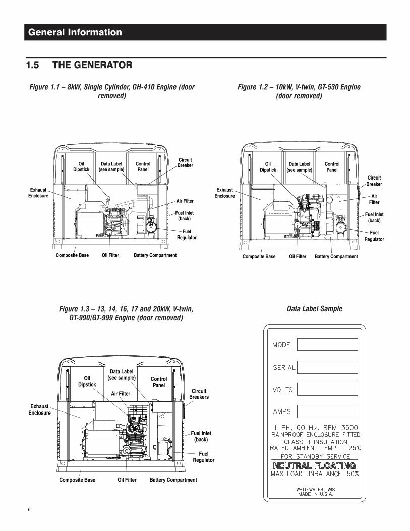
Figure 1.3 � 13, 14, 16, 17 and 20kW, V-twin, GT-990/GT-999 Engine (door removed)
Figure 1.1 � 8kW, Single Cylinder, GH-410 Engine (door removed)
Figure 1.2 � 10kW, V-twin, GT-530 Engine (door removed)
Data Label Sample
General Information
7
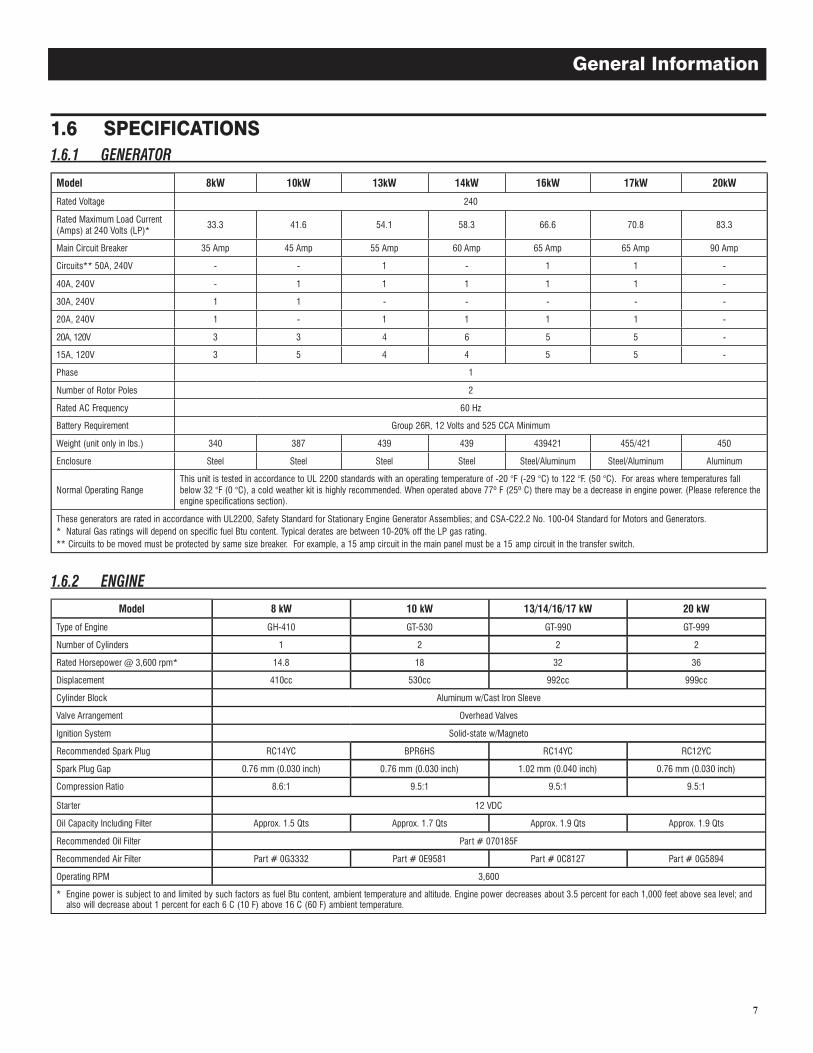
Model 8kW 10kW 13kW 14kW 16kW 17kW 20kW
Rated Voltage 240
Rated Maximum Load Current (Amps) at 240 Volts (LP)*
33.3 41.6 54.1 58.3 66.6 70.8 83.3
Main Circuit Breaker 35 Amp 45 Amp 55 Amp 60 Amp 65 Amp 65 Amp 90 Amp
Circuits** 50A, 240V - - 1 - 1 1 -
40A, 240V - 1 1 1 1 1 -
30A, 240V 1 1 - - - - -
20A, 240V 1 - 1 1 1 1 -
20A, 120V 3 3 4 6 5 5 -
15A, 120V 3 5 4 4 5 5 -
Phase 1
Number of Rotor Poles 2
Rated AC Frequency 60 Hz
Battery Requirement Group 26R, 12 Volts and 525 CCA Minimum
Weight (unit only in lbs.) 340 387 439 439 439421 455/421 450
Enclosure Steel Steel Steel Steel Steel/Aluminum Steel/Aluminum Aluminum
Normal Operating RangeThis unit is tested in accordance to UL 2200 standards with an operating temperature of -20 °F (-29 °C) to 122 °F. (50 °C). For areas where temperatures fall below 32 °F (0 °C), a cold weather kit is highly recommended. When operated above 77º F (25º C) there may be a decrease in engine power. (Please reference the engine specifications section).
These generators are rated in accordance with UL2200, Safety Standard for Stationary Engine Generator Assemblies; and CSA-C22.2 No. 100-04 Standard for Motors and Generators.* Natural Gas ratings will depend on specific fuel Btu content. Typical derates are between 10-20% off the LP gas rating.** Circuits to be moved must be protected by same size breaker. For example, a 15 amp circuit in the main panel must be a 15 amp circuit in the transfer switch.
Model 8 kW 10 kW 13/14/16/17 kW 20 kW
Type of Engine GH-410 GT-530 GT-990 GT-999
Number of Cylinders 1 2 2 2
Rated Horsepower @ 3,600 rpm* 14.8 18 32 36
Displacement 410cc 530cc 992cc 999cc
Cylinder Block Aluminum w/Cast Iron Sleeve
Valve Arrangement Overhead Valves
Ignition System Solid-state w/Magneto
Recommended Spark Plug RC14YC BPR6HS RC14YC RC12YC
Spark Plug Gap 0.76 mm (0.030 inch) 0.76 mm (0.030 inch) 1.02 mm (0.040 inch) 0.76 mm (0.030 inch)
Compression Ratio 8.6:1 9.5:1 9.5:1 9.5:1
Starter 12 VDC
Oil Capacity Including Filter Approx. 1.5 Qts Approx. 1.7 Qts Approx. 1.9 Qts Approx. 1.9 Qts
Recommended Oil Filter Part # 070185F
Recommended Air Filter Part # 0G3332 Part # 0E9581 Part # 0C8127 Part # 0G5894
Operating RPM 3,600
* Engine power is subject to and limited by such factors as fuel Btu content, ambient temperature and altitude. Engine power decreases about 3.5 percent for each 1,000 feet above sea level; and also will decrease about 1 percent for each 6 C (10 F) above 16 C (60 F) ambient temperature.
General Information
The "Ready to Run" on the display is ready when all of the following conditions are true:
1. The AUTO/OFF/MANUAL switch is set to the AUTO position.2. The utility voltage being supplied to the unit is being sensed
by the PCB. If the utility sense voltage is not connected to the unit or if it is below approximately 150-160 volts AC, then the system will display the message "No Utility Present". This indicates that if the AUTO/OFF/MANUAL switch is placed in the Auto position, the generator will start.
3. No alarms are present, for example, low oil pressure, high temperature, etc.
With LP gas, use only the vapor withdrawal system. This type of system uses the vapors formed above the liquid fuel in the storage tank.
The engine has been fitted with a fuel carburetion system that meets the specifications of the 1997 California Air Resources Board for tamper-proof dual fuel systems. The unit will run on natural gas or LP gas, but it has been factory set to run on natural gas. Should the primary fuel need to be changed to LP gas, the fuel system needs to be reconfigured. See the reconfiguring the Fuel System section for instructions on reconfiguration of the fuel system.
Recommended fuels should have a Btu content of at least 1,000 Btus per cubic foot for natural gas; or at least 2,520 Btus per cubic foot for LP gas. Ask the fuel supplier for the Btu content of the fuel.
Required fuel pressure for natural gas is five (5) inches to seven (7) inches water column (0.18 to 0.25 psi); and for liquid pro-pane, 10 inches to 12 inches of water column (0.36 to 0.43 psi). The primary regulator for the propane supply is NOT INCLUDED with the generator.
NOTE:
All pipe sizing, construction and layout must comply with NFPA 54 for natural gas applications and NFPA 58 for liquid propane applications. Once the generator is installed, verify that the fuel pressure NEVER drops more than one (1) inch water column from no load to full load from the starting pressure for either fuel type, and remains within the limits of the stated specifica-tion.
Prior to installation of the generator, the installer should consult local fuel suppliers or the fire marshal to check codes and regula-tions for proper installation. Local codes will mandate correct rout-ing of gaseous fuel line piping around gardens, shrubs and other landscaping to prevent any damage.
Special considerations should be given when installing the unit where local conditions include flooding, tornados, hurricanes, earthquakes and unstable ground for the flexibility and strength of piping and their connections.
Use an approved pipe sealant or joint compound on all threaded fittings.
All installed gaseous fuel piping must be purged and leak tested prior to initial start-up in accordance with local codes, standards and regulations.
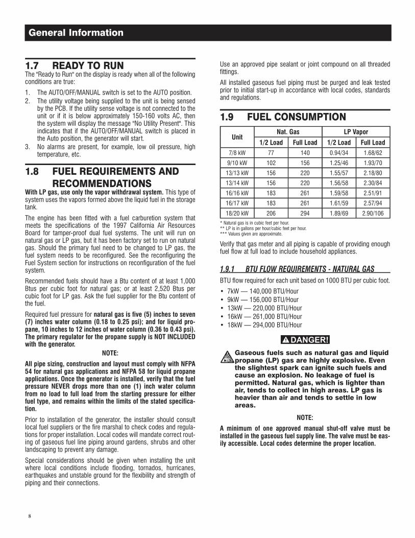
UnitNat. Gas LP Vapor
1/2 Load Full Load 1/2 Load Full Load7/8 kW 77 140 0.94/34 1.68/62
9/10 kW 102 156 1.25/46 1.93/70
13/13 kW 156 220 1.55/57 2.18/80
13/14 kW 156 220 1.56/58 2.30/84
16/16 kW 183 261 1.59/58 2.51/91
16/17 kW 183 261 1.61/59 2.57/94
18/20 kW 206 294 1.89/69 2.90/106* Natural gas is in cubic feet per hour.** LP is in gallons per hour/cubic feet per hour.*** Values given are approximate.
Verify that gas meter and all piping is capable of providing enough fuel flow at full load to include household appliances.
BTU flow required for each unit based on 1000 BTU per cubic foot.
• 7kW — 140,000 BTU/Hour• 9kW — 156,000 BTU/Hour• 13kW — 220,000 BTU/Hour• 16kW — 261,000 BTU/Hour• 18kW — 294,000 BTU/Hour
Gaseous fuels such as natural gas and liquid propane (LP) gas are highly explosive. Even the slightest spark can ignite such fuels and cause an explosion. No leakage of fuel is permitted. Natural gas, which is lighter than air, tends to collect in high areas. LP gas is heavier than air and tends to settle in low areas.
NOTE:
A minimum of one approved manual shut-off valve must be installed in the gaseous fuel supply line. The valve must be eas-ily accessible. Local codes determine the proper location.
8
General Information
9
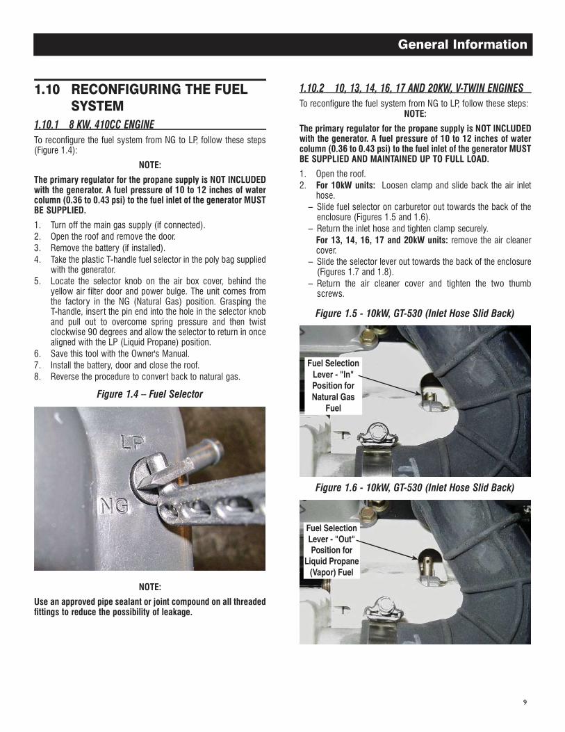
To reconfigure the fuel system from NG to LP, follow these steps (Figure 1.4):
NOTE:
The primary regulator for the propane supply is NOT INCLUDED with the generator. A fuel pressure of 10 to 12 inches of water column (0.36 to 0.43 psi) to the fuel inlet of the generator MUST BE SUPPLIED.
1. Turn off the main gas supply (if connected).2. Open the roof and remove the door.3. Remove the battery (if installed).4. Take the plastic T-handle fuel selector in the poly bag supplied
with the generator.5. Locate the selector knob on the air box cover, behind the
yellow air filter door and power bulge. The unit comes from the factory in the NG (Natural Gas) position. Grasping the T-handle, inser t the pin end into the hole in the selector knob and pull out to overcome spring pressure and then twist clockwise 90 degrees and allow the selector to return in once aligned with the LP (Liquid Propane) position.
6. Save this tool with the Owner's Manual.7. Install the battery, door and close the roof.8. Reverse the procedure to convert back to natural gas.
Figure 1.4 � Fuel Selector
NOTE:
Use an approved pipe sealant or joint compound on all threaded fittings to reduce the possibility of leakage.
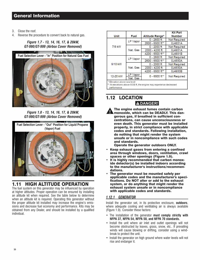
To reconfigure the fuel system from NG to LP, follow these steps:NOTE:
The primary regulator for the propane supply is NOT INCLUDED with the generator. A fuel pressure of 10 to 12 inches of water column (0.36 to 0.43 psi) to the fuel inlet of the generator MUST BE SUPPLIED AND MAINTAINED UP TO FULL LOAD.
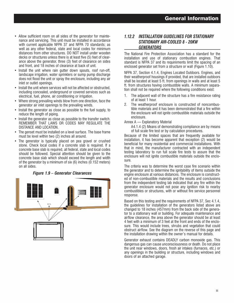
1. Open the roof.2. For 10kW units: Loosen clamp and slide back the air inlet
hose.– Slide fuel selector on carburetor out towards the back of the
enclosure (Figures 1.5 and 1.6).– Return the inlet hose and tighten clamp securely.
For 13, 14, 16, 17 and 20kW units: remove the air cleaner cover.
– Slide the selector lever out towards the back of the enclosure (Figures 1.7 and 1.8).
– Return the air cleaner cover and tighten the two thumb screws.
Figure 1.5 - 10kW, GT-530 (Inlet Hose Slid Back)
Figure 1.6 - 10kW, GT-530 (Inlet Hose Slid Back)
General Information
10
3. Close the roof.4. Reverse the procedure to convert back to natural gas.
Figure 1.7 - 13, 14, 16, 17, & 20kW,GT-990/GT-999 (Airbox Cover Removed)
Figure 1.8 - 13, 14, 16, 17, & 20kW,GT-990/GT-999 (Airbox Cover Removed)
The fuel system on this generator may be influenced by operation at higher altitudes. Proper operation can be ensured by installing an altitude kit when required. See the table below to determine when an altitude kit is required. Operating this generator without the proper altitude kit installed may increase the engine’s emis-sions and decrease fuel economy and performance. Kits may be obtained from any Dealer, and should be installed by a qualified individual.
The engine exhaust fumes contain carbon monoxide, which can be DEADLY. This dan-gerous gas, if breathed in sufficient con-centrations, can cause unconsciousness or even death. This generator must be installed properly, in strict compliance with applicable codes and standards. Following installation, do nothing that might render the system unsafe or in noncompliance with such codes and standards.Operate the generator outdoors ONLY.
• Keep exhaust gases from entering a confined area through windows, doors, ventilation, crawl spaces or other openings (Figure 1.9).
• It is highly recommended that carbon monox-ide detector(s) be installed indoors according to the manufacturer's instructions/recommen-dations.
• The generator must be mounted safely per applicable codes and the manufacturer's speci-fications. Do NOT alter or add to the exhaust system, or do anything that might render the exhaust system unsafe or in noncompliance with applicable codes and standards.
Install the generator set, in its protective enclosure, outdoors, where adequate cooling and ventilating air is always available (Figure 1.9). Consider these factors:
• The installation of the generator must comply strictly with NFPA 37, NFPA 54, NFPA 58, and NFPA 70 standards.
• Install the unit where air inlet and outlet openings will not become obstructed by leaves, grass, snow, etc.. If prevailing winds will cause blowing or drifting, consider using a wind-break to protect the unit.
• Install the generator on high ground where water levels will not rise and endanger it.
General Information
11
� Allow sufficient room on all sides of the generator for mainte-nance and servicing. This unit must be installed in accordance with current applicable NFPA 37 and NFPA 70 standards; as well as any other federal, state and local codes for minimum distances from other structures. DO NOT install under wooden decks or structures unless there is at least five (5) feet of clear-ance above the generator, three (3) feet of clearance on sides and front, and 18 inches of clearance at back of unit.
� Install the unit where rain gutter down spouts, roof run-off, landscape irrigation, water sprinklers or sump pump discharge does not flood the unit or spray the enclosure, including any air inlet or outlet openings.
� Install the unit where services will not be affected or obstructed, including concealed, underground or covered services such as electrical, fuel, phone, air conditioning or irrigation.
� Where strong prevailing winds blow from one direction, face the generator air inlet openings to the prevailing winds.
� Install the generator as close as possible to the fuel supply, to reduce the length of piping.
� Install the generator as close as possible to the transfer switch. REMEMBER THAT LAWS OR CODES MAY REGULATE THE DISTANCE AND LOCATION.
� The genset must be installed on a level surface. The base frame must be level within two (2) inches all around.
� The generator is typically placed on pea gravel or crushed stone. Check local codes if a concrete slab is required. If a concrete base slab is required, all federal, state and local codes should be followed. Special attention should be given to the concrete base slab which should exceed the length and width of the generator by a minimum of six (6) inches (0.152 meters) on all sides.
Figure 1.9 � Generator Clearances
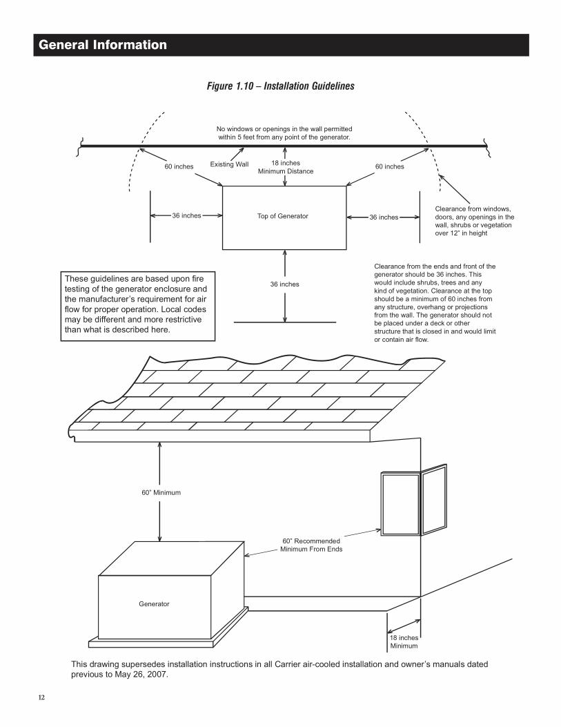
The National Fire Protection Association has a standard for the installation and use of stationary combustion engines. That standard is NFPA 37 and its requirements limit the spacing of an enclosed generator set from a structure or wall (Figure 1.10).
NFPA 37, Section 4.1.4, Engines Located Outdoors. Engines, and their weatherproof housings if provided, that are installed outdoors shall be located at least 5 ft. from openings in walls and at least 5 ft. from structures having combustible walls. A minimum separa-tion shall not be required where the following conditions exist:
1. The adjacent wall of the structure has a fire resistance rating of at least 1 hour.
2. The weatherproof enclosure is constructed of noncombus-tible materials and it has been demonstrated that a fire within the enclosure will not ignite combustible materials outside the enclosure.
Annex A � Explanatory Material A4.1.4 (2) Means of demonstrating compliance are by means
of full scale fire test or by calculation procedures.Because of the limited spaces that are frequently available for installation, it has become apparent that exception (2) would be beneficial for many residential and commercial installations. With that in mind, the manufacturer contracted with an independent testing laboratory to run full scale fire tests to assure that the enclosure will not ignite combustible materials outside the enclo-sure.
The criteria was to determine the worst case fire scenario within the generator and to determine the ignitability of items outside the engine enclosure at various distances. The enclosure is construct-ed of non-combustible materials and the results and conclusions from the independent testing lab indicated that any fire within the generator enclosure would not pose any ignition risk to nearby combustibles or structures, with or without fire service personnel response.
Based on this testing and the requirements of NFPA 37, Sec 4.1.4, the guidelines for installation of the generators listed above are changed to 18 inches (457mm) from the back side of the genera-tor to a stationary wall or building. For adequate maintenance and airflow clearance, the area above the generator should be at least 4 feet with a minimum of 3 feet at the front and ends of the enclo-sure. This would include trees, shrubs and vegetation that could obstruct airflow. See the diagram on the reverse of this page and the installation drawing within the owner�s manual for details.
Generator exhaust contains DEADLY carbon monoxide gas. This dangerous gas can cause unconsciousness or death. Do not place the unit near windows, doors, fresh air intakes (furnaces, etc.) or any openings in the building or structure, including windows and doors of an attached garage.
General Information
12
Figure 1.10 � Installation Guidelines
General Information
13
If the AUTO/OFF/MANUAL switch is not set to its OFF position, the generator can crank and start as soon as the battery cables are connected. If the utility power supply is not turned off, sparking can occur at the battery posts and cause an explosion.
See the Specifications section for correct battery size and rating.
Fill the battery with the proper electrolyte fluid if necessary and have the battery fully charged before installing it.
Before installing and connecting the battery, complete the follow-ing steps:
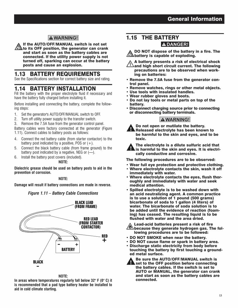
1. Set the generator's AUTO/OFF/MANUAL switch to OFF.2. Turn off utility power supply to the transfer switch.3. Remove the 7.5A fuse from the generator control panel.Battery cables were factory connected at the generator (Figure 1.11). Connect cables to battery posts as follows:
4. Connect the red battery cable (from starter contactor) to the battery post indicated by a positive, POS or (+).
5. Connect the black battery cable (from frame ground) to the battery post indicated by a negative, NEG or (—).
6. Install the battery post covers (included).NOTE:
Dielectric grease should be used on battery posts to aid in the prevention of corrosion.
NOTE:
Damage will result if battery connections are made in reverse.
Figure 1.11 � Battery Cable Connections
NOTE:In areas where temperatures regularly fall below 32° F (0° C) it is recommended that a pad type battery heater be installed to aid in cold climate starting.
DO NOT dispose of the battery in a fire. The battery is capable of exploding.
A battery presents a risk of electrical shock and high short circuit current. The following precautions are to be observed when work-ing on batteries:
• Remove the 7.5A fuse from the generator con-trol panel.
• Remove watches, rings or other metal objects.• Use tools with insulated handles.• Wear rubber gloves and boots.• Do not lay tools or metal parts on top of the
battery.• Disconnect charging source prior to connecting
or disconnecting battery terminals.
Do not open or mutilate the battery. Released electrolyte has been known to be harmful to the skin and eyes, and to be toxic.
The electrolyte is a dilute sulfuric acid that is harmful to the skin and eyes. It is electri-cally conductive and corrosive.
The following procedures are to be observed:• Wear full eye protection and protective clothing.• Where electrolyte contacts the skin, wash it off
immediately with water.• Where electrolyte contacts the eyes, flush thor-
oughly and immediately with water and seek medical attention.
• Spilled electrolyte is to be washed down with an acid neutralizing agent. A common practice is to use a solution of 1 pound (500 grams) bicarbonate of soda to 1 gallon (4 liters) of water. The bicarbonate of soda solution is to be added until the evidence of reaction (foam-ing) has ceased. The resulting liquid is to be flushed with water and the area dried.
Lead-acid batteries present a risk of fire because they generate hydrogen gas. The fol-lowing procedures are to be followed:
• DO NOT SMOKE when near the battery.• DO NOT cause flame or spark in battery area.• Discharge static electricity from body before
touching the battery by first touching a ground-ed metal surface.
Be sure the AUTO/OFF/MANUAL switch is set to the OFF position before connecting the battery cables. If the switch is set to AUTO or MANUAL, the generator can crank and start as soon as the battery cables are connected.
General Information
14
Be sure the utility power supply is turned off and the 7.5A fuse is removed from the gener-ator control panel, or sparking may occur at the battery posts as the cables are attached and cause an explosion.
Servicing of the battery is to be performed or supervised by per-sonnel knowledgeable of batteries and the required precautions. Keep unauthorized personnel away from batteries.
See the Specifications section for the correct size and rating when replacing the battery. Have these procedures performed at the intervals specified in the “Service Schedule.” A negative ground system is used. Battery connections are shown on the wiring dia-grams. Make sure the battery is correctly connected and terminals are tight. Observe battery polarity when connecting the battery to the generator set.
NOTE:
The battery charger is integrated into the control module in all models.It operates as a "Smart Charger" which ensures output is continu-ally optimized to promote maximum battery life and charging levels are at safe conditions.
NOTE:
There is a warning on the LCD display when the battery needs service.
When battery power is applied to the generator during the installa-tion process, the controller will light up. However, the generator still needs to be activated before it will automatically run in the event of a power outage.
Activating the generator is a simple one time process that is guided by the controller screen prompts. Once the product is activated, the controller screen will not prompt you again, even if you discon-nect the generator battery.
After obtaining your activation code, please complete the following steps at the generator’s control panel as outlined by the Activation Char t.
NOTE:
These units have been run and tested at the factory prior to being shipped and do not require any type of break-in.
NOTE:
This unit comes filled with oil from the factory. Check the oil level and add the appropriate amount if necessary.
Before starting, complete the following:
1. Set the generator’s main circuit breaker to its OFF (or OPEN) position.
2. Set the generator's AUTO/OFF/MANUAL switch to the OFF position.
3. Turn OFF all breakers on the load center of the transfer box (T1 and T2).
4. Turn OFF all loads connected to the transfer switch terminals T1 and T2.
5. Check the engine crankcase oil level and, if necessary, fill to the dipstick FULL mark with the recommended oil. Do not fill above the FULL mark.
6. Check the fuel supply. Gaseous fuel lines must have been properly purged and leak tested in accordance with applicable fuel-gas codes. All fuel shutoff valves in the fuel supply lines must be open.
During initial start up only, the generator may exceed the normal number of start attempts and experience an “over crank” fault (See the "Overcrank" section). This is due to accumulated air in the fuel system during installation. Reset the control board and restart up to two more times, if necessary. If unit fails to start, contact the local dealer for assistance.
Never operate the engine with the oil level below the “Add” mark on the dipstick. Doing this could damage the engine.
Refer to the "Manual Transfer Operation" section, of the owner’s manual for procedures.
Do not attempt manual transfer switch opera-tion until all power voltage supplies to the transfer switch have been positively turned off. Failure to turn off all power voltage sup-plies will result in extremely hazardous and possibly fatal electrical shock.
Complete electrical checks as follows:
1. Set the generator's main circuit breaker to its OFF (or OPEN) position.
2. Set the generator's AUTO/OFF/MANUAL switch to the OFF position.
3. Turn OFF all breakers on the load center of the transfer box (T1 and T2).
4. Turn on the utility power supply to the transfer switch using the means provided (such as a utility main line circuit break-er).
The transfer switch is now electrically “hot.” Contact with “hot” parts will result in extremely hazardous and possibly fatal electrical shock. Proceed with caution.
5. Use an accurate AC voltmeter to check utility power source voltage across transfer switch terminals N1 and N2. Nominal line-to-line voltage should be 240 volts AC.
Post Installation Start-up and Adjustments
15
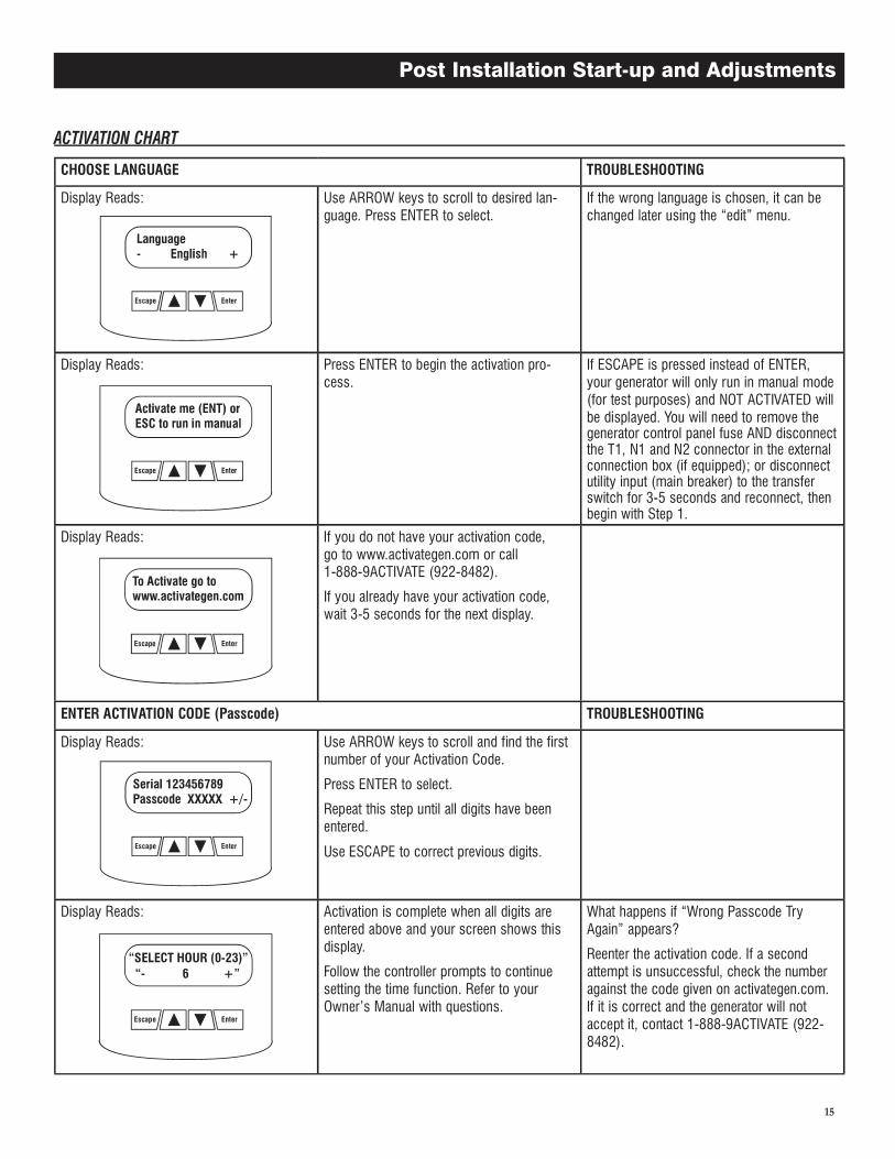
CHOOSE LANGUAGE TROUBLESHOOTING
Display Reads: Use ARROW keys to scroll to desired lan-guage. Press ENTER to select.
If the wrong language is chosen, it can be changed later using the “edit” menu.
Display Reads: Press ENTER to begin the activation pro-cess.
If ESCAPE is pressed instead of ENTER, your generator will only run in manual mode (for test purposes) and NOT ACTIVATED will be displayed. You will need to remove the generator control panel fuse AND disconnect the T1, N1 and N2 connector in the external connection box (if equipped); or disconnect utility input (main breaker) to the transfer switch for 3-5 seconds and reconnect, then begin with Step 1.
Display Reads: If you do not have your activation code, go to www.activategen.com or call 1-888-9ACTIVATE (922-8482).
If you already have your activation code, wait 3-5 seconds for the next display.
ENTER ACTIVATION CODE (Passcode) TROUBLESHOOTING
Display Reads: Use ARROW keys to scroll and find the first number of your Activation Code.
Press ENTER to select.
Repeat this step until all digits have been entered.
Use ESCAPE to correct previous digits.
Display Reads: Activation is complete when all digits are entered above and your screen shows this display.
Follow the controller prompts to continue setting the time function. Refer to your Owner’s Manual with questions.
What happens if “Wrong Passcode Try Again” appears?
Reenter the activation code. If a second attempt is unsuccessful, check the number against the code given on activategen.com. If it is correct and the generator will not accept it, contact 1-888-9ACTIVATE (922-8482).
Escape Enter
Escape Enter
Escape Enter
Escape Enter
Escape Enter
Post Installation Start-up and Adjustments
16
6. Check utility power source voltage across terminals N1 and the transfer switch neutral lug; then across terminal N2 and neutral. Nominal line-to-neutral voltage should be 120 volts AC.
7. When cer tain that utility supply voltage is compatible with transfer switch and load circuit ratings, turn OFF the utility power supply to the transfer switch.
8. On the generator panel, set the Auto/Off/ Manual switch to MANUAL. The engine should crank and start.
9. Let the engine warm up for about five minutes to allow inter-nal temperatures to stabilize. Then, set the generator’s main circuit breaker to its ON (or closed) position.
Proceed with caution! Generator power volt-age is now supplied to the transfer switch. Contact with live transfer switch parts will result in dangerous and possibly fatal electri-cal shock.
10. Connect an accurate AC voltmeter and a frequency meter across transfer switch terminal lugs E1 and E2. Voltage should be 238-242 at a frequency of 59.5-60.5 Hertz.
11. Connect the AC voltmeter test leads across terminal lugs E1 and neutral; then across E2 and neutral. In both cases, voltage reading should be 119-121 volts AC.
12. Set the generator’s main circuit breaker to its OFF (or OPEN) position. Let the engine run at no-load for a few minutes to stabilize internal engine generator temperatures.
13. Set the generator's AUTO/OFF/MANUAL switch to OFF. The engine should shut down.
NOTE:
It is important not to proceed until certain that generator AC voltage and frequency are correct and within the stated limits.
To test the generator set with electrical loads applied, proceed as follows:
1. Set generator’s main circuit breaker to its OFF (or OPEN) posi-tion.
2. Turn OFF all breakers on the load center of the transfer box (T1 and T2).
3. Set the generator's AUTO/OFF/MANUAL switch to OFF.4. Turn OFF the utility power supply to the transfer switch,
using the means provided (such as a utility main line circuit breaker).
Do not attempt manual transfer switch opera-tion until all power voltage supplies to the transfer switch have been positively turned off. Failure to turn off all power voltage sup-plies will result in extremely hazardous and possibly fatal electrical shock.
5. Manually set the transfer switch to the STANDBY position, i.e., load terminals connected to the generator's E1/E2 terminals. The transfer switch operating lever should be down.
6. Set the generator's AUTO/OFF/MANUAL switch to MANUAL. The engine should crank and start immediately.
7. Let the engine stabilize and warm up for a few minutes.8. Set the generator’s main circuit breaker to its ON (or CLOSED)
position. Loads are now powered by the standby generator.9. Turn ON the load center of the transfer switch (T1 and T2).10. Connect an accurate AC voltmeter and a frequency meter
across terminal lugs E1 and E2.– Voltage should be greater than, or approximately 240 volts
and frequency should be 60 Hz.11. Let the generator run at full rated load for 20-30 minutes.
Listen for unusual noises, vibration or other indications of abnormal operation. Check for oil leaks, evidence of overheat-ing, etc.
12. When testing under load is complete, turn OFF electrical loads.
13. Set the generator's main circuit breaker to its OFF (or OPEN) position.
14. Let the engine run at no-load for a few minutes.15. Set the AUTO/OFF/MANUAL switch to OFF. The engine should
shut down.
To check the system for proper automatic operation, proceed as follows:
1. Set generator’s main circuit breaker to its OFF (or OPEN) posi-tion.
2. Check that the AUTO/OFF/MANUAL switch is set to OFF.3. Turn OFF the utility power supply to the transfer switch, using
means provided (such as a utility main line circuit breaker).4. Manually set the transfer switch to the UTILITY position, i.e.,
load terminals connected to the utility power source side.5. Turn ON the utility power supply to the transfer switch,
using the means provided (such as a utility main line circuit breaker).
6. Set the generator's main circuit breaker to its ON (or CLOSED) position.
7. Set the AUTO/OFF/MANUAL switch to AUTO. The system is now ready for automatic operation.
8. Turn OFF the utility power supply to the transfer switch.
With the AUTO/OFF/MANUAL switch at AUTO, the engine should crank and start when the utility source power is turned OFF after a 10 second delay. After starting, the transfer switch should connect load circuits to the standby side after a five (5) second delay. Let the system go through its entire automatic sequence of operation.
With the generator running and loads powered by generator AC output, turn ON the utility power supply to the transfer switch. The following should occur:
• After about 15 seconds, the switch should transfer loads back to the utility power source.
• About one minute after re-transfer, the engine should shut down.
Post Installation Start-up and Adjustments
17
With the switch set to AUTO, the engine may crank and start at any time without warning. Such automatic starting occurs when utility power source voltage drops below a preset level or during the normal exercise cycle. To prevent possible injury that might be caused by such sudden starts, always set the switch to OFF and remove the fuses before work-ing on or around the generator or transfer switch. Then, place a “DO NOT OPERATE” tag on the generator panel and on the trans-fer switch.
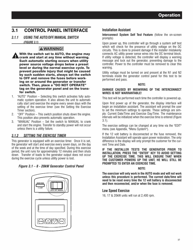
1. “AUTO” Position – Selecting this switch activates fully auto-matic system operation. It also allows the unit to automati-cally star t and exercise the engine every seven days with the setting of the exercise timer (see the Setting the Exercise Timer section).
2. “OFF” Position – This switch position shuts down the engine. This position also prevents automatic operation.
3. “MANUAL” Position – Set the switch to MANUAL to crank and start the engine. Transfer to standby power will not occur unless there is a utility failure.
This generator is equipped with an exercise timer. Once it is set, the generator will start and exercise every seven days, on the day of the week and at the time of day specified. During this exercise period, the unit runs for approximately 12 minutes and then shuts down. Transfer of loads to the generator output does not occur during the exercise cycle unless utility power is lost.
Figure 3.1 � 8 - 20kW Generator Control Panel
Interconnect System Self Test Feature (follow the on-screen prompts)
Upon power up, this controller will go through a system self test which will check for the presence of utility voltage on the DC circuits. This is done to prevent damage if the installer mistakenly connects AC utility power sense wires into the DC terminal block. If utility voltage is detected, the controller will display a warning message and lock out the generator, preventing damage to the controller. Power to the controller must be removed to clear this warning.
Utility voltage must be turned on and present at the N1 and N2 terminals inside the generator control panel for this test to be performed and pass.
NOTE:
DAMAGE CAUSED BY MISWIRING OF THE INTERCONNECT WIRES IS NOT WARRANTABLE!
This test will be performed each time the controller is powered up.
Upon first power up of the generator, the display interface will begin an installation assistant. The assistant will prompt the user to set the minimum settings to operate. These settings are sim-ply: Current Date/Time and Exercise Day/Time. The maintenance intervals will be initialized when the exercise time is entered (Figure 3.1).
The exercise settings can be changed at any time via the "EDIT" menu (see Appendix, "Menu System").
If the 12 volt battery is disconnected or the fuse removed, the Installation Assistant will operate upon power restoration. The only difference is the display will only prompt the customer for the cur-rent Time and Date.
IF THE INSTALLER TESTS THE GENERATOR PRIOR TO INSTALLATION, PRESS THE “ENTER” KEY TO AVOID SETTING UP THE EXERCISE TIME. THIS WILL ENSURE THAT WHEN THE CUSTOMER POWERS UP THE UNIT, HE WILL STILL BE PROMPTED TO ENTER AN EXERCISE TIME.
NOTE:
The exerciser will only work in the AUTO mode and will not work unless this procedure is performed. The current date/time will need to be reset every time the 12 volt battery is disconnected and then reconnected, and/or when the fuse is removed.
16, 17 & 20kW units will run at 2,400 rpm.
Operation
18
The LCD display is organized as detailed below:
• The “Home” page, this page is the default page which will be displayed if no keys are pressed for 30 seconds. This page normally shows the current Status message and the current date and time. The highest priority active Alarm and/or Warning will be automatically posted on this page as well as flashing the backlight when such an event is detected. In the case of multiple Alarms or Warnings, only the first message will be displayed. To clear an Alarm or Warning, see the Protection Systems section - Clear Alarm.
• The display backlight is normally off. If the user presses any key, the backlight will come on automatically and remain on for 30 seconds after the last key was pressed.
• The “Main Menu” page will allow the user to navigate to all other pages or sub-menus by using the Left/Right and Enter keys. This page can be accessed at any time with several presses of the dedicated Escape key. Each press of the Escape key takes you back to the previous menu until the main menu is reached. This page displays the following options: HISTORY; STATUS; EDIT; AND DEBUG. (See the Appendix - "Menu System".)
To select automatic operation, do the following:
1. Make sure the transfer switch main contacts are set to their UTILITY position, i.e., loads connected to the utility power source (Figure 3.1).
2. Be sure that normal UTILITY power source voltage is avail-able to transfer switch terminal lugs N1 and N2 (Refer to the Electrical Data section).
3. Set the generator’s AUTO/OFF/MANUAL switch to AUTO.4. Set the generator’s main circuit breaker to its ON (or CLOSED)
position.With the preceding steps complete, the generator will start auto-matically when utility source voltage drops below a preset level. After the unit star ts, loads are transferred to the standby power source. Refer to the Sequence of Automatic Operation section.
Initial Conditions: Generator in Auto, ready to run, load being sup-plied by utility source. When utility fails (below 60% of nominal), a 10 second (optionally programmable) line interrupt delay time is started. If the utility is still gone when the timer expires, the engine will crank and start. Once started, a five (5) second engine warm-up timer will be initiated. When the warm-up timer expires, the control will transfer the load to the generator. If the utility power is restored (above 80% of nominal) at any time from the initiation of the engine start until the generator is ready to accept load (5 sec-ond warm-up time has not elapsed), the controller will complete the start cycle and run the generator through its normal cool down cycle; however, the load will remain on the utility source.
The system will control the cyclic cranking as follows: 16 second crank, seven (7) second rest, 16 second crank, seven (7) second rest followed by three (3) additional cycles of seven (7) second cranks followed by seven (7) second rests.
1. The 990/999cc engines have an electric choke in the air box that is automatically controlled by the electronic control board.
2. The 530cc engines have an electric choke on the divider panel air inlet hose that is automatically controlled by the electronic control board.
3. The 410cc engines have a choke behind the air box that is automatically controlled by the electronic control board.
This is defined as any of the following occurrences during crank-ing:
1. Not reaching starter dropout within the specified crank cycle. Star ter dropout is defined as four (4) cycles at 1,000 RPM.
2. Reaching starter dropout, but then not reaching 2200 RPM within 15 seconds. In this case the control board will go into a rest cycle for seven (7) seconds, then continue the rest of the crank cycle.
During a rest cycle the start and fuel outputs are de-energized and the magneto output is shorted to ground.
The following notes apply during cranking cycle.
1. Star ter motor will not engage within five (5) seconds of the engine shutting down.
2. The fuel output will not be energized with the starter.3. The starter and magneto outputs will be energized together.4. Once the starter is energized the control board will begin look-
ing for engine rotation. If it does not see an RPM signal within three (3) seconds it will shut down and latch out on RPM sensor loss.
5. Once the control board sees an RPM signal it will energize the fuel solenoid, drive the throttle open and continue the crank sequence.
6. Star ter motor will disengage when speed reaches starter dropout.
7. If the generator does not reach 2200 RPM within 15 seconds, re-crank cycle will occur.
8. If engine stops turning between starter dropout and 2200 RPM, the board will go into a rest cycle for seven (7) seconds then re-crank (if additional crank cycles exist).
9. Once star ted, the generator will wait for a hold-off period before starting to monitor oil pressure and oil temperature (refer to the Alarm Messages section for hold-off times).
10. During Manual start cranking, if the Mode switch is moved from the Manual position, the cranking stops immediately.
11. During Auto mode cranking, if the Utility returns, the cranking cycle does NOT abort but continues until complete. Once the engine starts, it will run for one (1) minute, then shut down.
Operation
19
The transfer of load when the generator is running is dependent upon the operating mode as follows:
1. Manual– Will not transfer to generator if utility is present.– Will transfer to generator if utility fails (below 65% of nominal for
10 consecutive seconds.– Will transfer back when utility returns for 15 consecutive sec-
onds. The engine will continue to run until removed from the Manual mode.
2. Auto– Will start and run if Utility fails for 10 consecutive seconds.– Will start a five (5) second engine warm-up timer.– Will not transfer if utility subsequently returns.– Will transfer to generator if utility is still not present.– Will transfer back to utility once utility returns (above 75% of
nominal) for 15 seconds.– Will transfer back to utility if the generator is shut down for any
reason (such as the switch is in the OFF position or a shutdown alarm.
– After transfer, will shut down engine after one (1) minute cool-down time.
3. Exercise– Will not exercise if generator is already running in either Auto or
Manual mode.– During exercise, the controller will only transfer if utility fails
during exercise for 10 seconds, and will switch to Auto mode.
Initial Condition: Generator supplying power to customer load. When the utility returns (above 80% of nominal), a 15 second return to utility timer will start. At the completion of this timer, if the utility supply is still present and acceptable, the control will transfer the load back to the utility and run the engine through a one (1) minute cool down period and then shut down. If utility fails for three (3) seconds during this cool down period, the control will transfer load back to the generator and continue to run while monitoring for utility to return.
To start the generator and activate the transfer switch manually, proceed as follows:
1. Set the generator’s AUTO/OFF/MANUAL switch to OFF.2. Set the generator’s main circuit breaker to its OFF (or OPEN)
position.3. Turn OFF the utility power supply to the transfer switch
using the means provided (such as a utility main line circuit breaker).
Do not attempt to activate the transfer switch manually until all power voltage supplies to the switch have been positively turned off. Failure to turn off all power voltage supplies may result in extremely hazardous and pos-sibly fatal electrical shock.
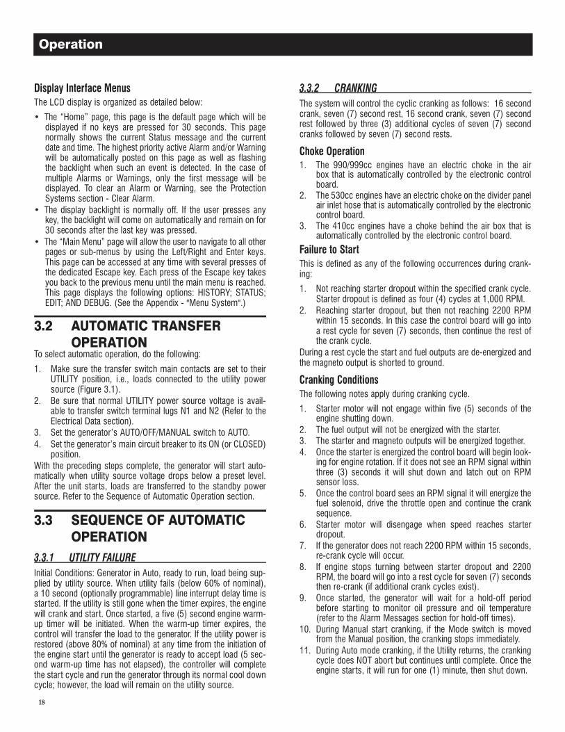
4. Use the manual transfer handle inside the transfer switch to move the main contacts to their STANDBY position, i.e., loads connected to the standby power source (Figure 3.2).
5. To crank and start the engine, set the AUTO/OFF/MANUAL switch to MANUAL.
6. Let the engine stabilize and warm up for a few minutes.7. Set the generator’s main circuit breaker to its ON (or CLOSED)
position. The standby power source now powers the loads.
Figure 3.2 � Manual Transfer Switch Operation
When utility power has been restored, transfer back to that source and shut down the generator. This can be accomplished as fol-lows:
1. Set the generator’s main circuit breaker to its OFF (or OPEN) position.
2. Let the engine run for a minute or two at no-load to stabilize the internal temperatures.
3. Set the generator’s AUTO/OFF/MANUAL switch to its OFF (or OPEN) position. The engine should shut down.
4. Check that utility power supply to the transfer switch is turned OFF.
Do not attempt to activate the transfer switch manually until all power voltage supplies to the switch have been positively turned off. Failure to turn off all power voltage supplies may result in extremely hazardous and pos-sibly fatal electrical shock.
Operation
20
5. Use the manual transfer handle inside the transfer switch to move the main contacts back to their UTILITY position, i.e., loads connected to the utility power source (Figure 3.2).
6. Turn ON the utility power supply to the transfer switch using the means provided.
7. Set the system to automatic operation as outlined in Automatic Transfer Operation section.
Local codes may require this compartment to be locked. A hasp is provided so the owner can secure the compartment with their own padlock. Check local codes in the area.
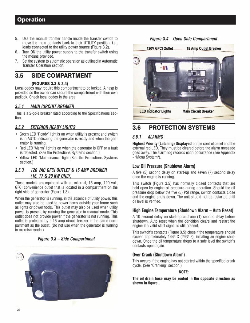
This is a 2-pole breaker rated according to the Specifications sec-tion.
• Green LED ‘Ready’ light is on when utility is present and switch is in AUTO indicating the generator is ready and when the gen-erator is running.
• Red LED ‘Alarm’ light is on when the generator is OFF or a fault is detected. (See the Protections Systems section.)
• Yellow LED ‘Maintenance’ light (See the Protections Systems section.)
These models are equipped with an external, 15 amp, 120 volt, GFCI convenience outlet that is located in a compartment on the right side of generator (Figure 1.3).
When the generator is running, in the absence of utility power, this outlet may also be used to power items outside your home such as lights or power tools. This outlet may also be used when utility power is present by running the generator in manual mode. This outlet does not provide power if the generator is not running. This outlet is protected by a 15 amp circuit breaker in the same com-partment as the outlet. (Do not use when the generator is running in exercise mode.)
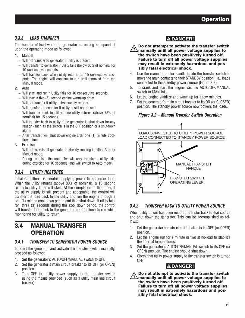
Figure 3.3 � Side Compartment
Figure 3.4 � Open Side Compartment
Highest Priority (Latching) Displayed on the control panel and the external red LED. They must be cleared before the alarm message goes away. The alarm log records each occurrence (see Appendix - "Menu System").
A five (5) second delay on start-up and seven (7) second delay once the engine is running.
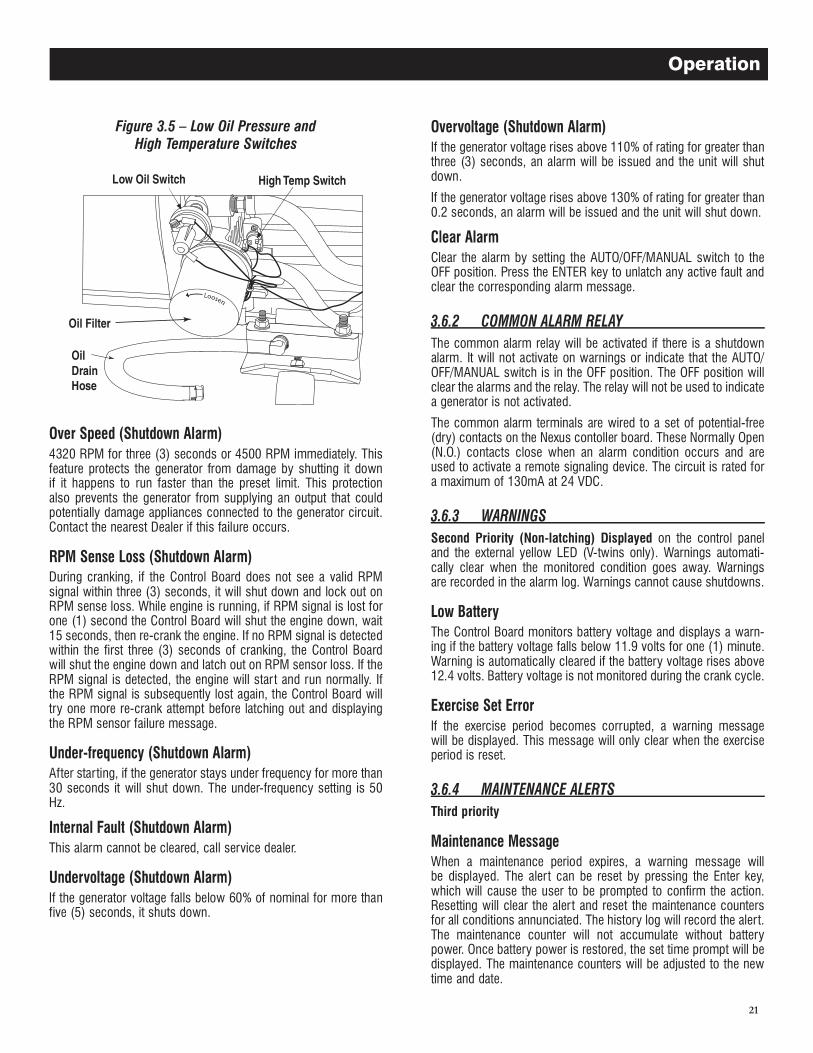
This switch (Figure 3.5) has normally closed contacts that are held open by engine oil pressure during operation. Should the oil pressure drop below the five (5) PSI range, switch contacts close and the engine shuts down. The unit should not be restarted until oil level is verified.
A 10 second delay on start-up and one (1) second delay before shutdown. Auto reset when the condition clears and restart the engine if a valid start signal is still present.
This switch’s contacts (Figure 3.5) close if the temperature should exceed approximately 144° C (293° F), initiating an engine shut-down. Once the oil temperature drops to a safe level the switch’s contacts open again.
This occurs if the engine has not started within the specified crank cycle. (See "Cranking" section.)
NOTE:
The oil drain hose may be routed in the opposite direction as shown in figure.
Operation
21
Figure 3.5 � Low Oil Pressure and High Temperature Switches
4320 RPM for three (3) seconds or 4500 RPM immediately. This feature protects the generator from damage by shutting it down if it happens to run faster than the preset limit. This protection also prevents the generator from supplying an output that could potentially damage appliances connected to the generator circuit. Contact the nearest Dealer if this failure occurs.
During cranking, if the Control Board does not see a valid RPM signal within three (3) seconds, it will shut down and lock out on RPM sense loss. While engine is running, if RPM signal is lost for one (1) second the Control Board will shut the engine down, wait 15 seconds, then re-crank the engine. If no RPM signal is detected within the first three (3) seconds of cranking, the Control Board will shut the engine down and latch out on RPM sensor loss. If the RPM signal is detected, the engine will start and run normally. If the RPM signal is subsequently lost again, the Control Board will try one more re-crank attempt before latching out and displaying the RPM sensor failure message.
After starting, if the generator stays under frequency for more than 30 seconds it will shut down. The under-frequency setting is 50 Hz.
This alarm cannot be cleared, call service dealer.
If the generator voltage falls below 60% of nominal for more than five (5) seconds, it shuts down.
If the generator voltage rises above 110% of rating for greater than three (3) seconds, an alarm will be issued and the unit will shut down.
If the generator voltage rises above 130% of rating for greater than 0.2 seconds, an alarm will be issued and the unit will shut down.
Clear the alarm by setting the AUTO/OFF/MANUAL switch to the OFF position. Press the ENTER key to unlatch any active fault and clear the corresponding alarm message.
The common alarm relay will be activated if there is a shutdown alarm. It will not activate on warnings or indicate that the AUTO/OFF/MANUAL switch is in the OFF position. The OFF position will clear the alarms and the relay. The relay will not be used to indicate a generator is not activated.
The common alarm terminals are wired to a set of potential-free (dry) contacts on the Nexus contoller board. These Normally Open (N.O.) contacts close when an alarm condition occurs and are used to activate a remote signaling device. The circuit is rated for a maximum of 130mA at 24 VDC.
Second Priority (Non-latching) Displayed on the control panel and the external yellow LED (V-twins only). Warnings automati-cally clear when the monitored condition goes away. Warnings are recorded in the alarm log. Warnings cannot cause shutdowns.
The Control Board monitors battery voltage and displays a warn-ing if the battery voltage falls below 11.9 volts for one (1) minute. Warning is automatically cleared if the battery voltage rises above 12.4 volts. Battery voltage is not monitored during the crank cycle.
If the exercise period becomes corrupted, a warning message will be displayed. This message will only clear when the exercise period is reset.
Third priority
When a maintenance period expires, a warning message will be displayed. The alert can be reset by pressing the Enter key, which will cause the user to be prompted to confirm the action. Resetting will clear the alert and reset the maintenance counters for all conditions annunciated. The history log will record the alert. The maintenance counter will not accumulate without battery power. Once battery power is restored, the set time prompt will be displayed. The maintenance counters will be adjusted to the new time and date.
Operation
22
NOTE:
Since most maintenance alerts will occur at the same time (most have two (2) year intervals), only one will appear on the display at any one time. Once the first alert is cleared, the next active alert will be displayed.
To safely stop and start a loaded generator follow these steps.
1. At the main service distribution panel, open (turn off) the main service entrance breaker.
1. Turn the Main Circuit Breaker off (Figure 3.6).2. If generator has a GFCI Outlet and it is being used, turn off the
15 Amp Outlet Breaker (Figure 3.6).3. Allow the generator to run for 1 minute without load to cool
down.
Figure 3.6 � Open Side Compartment
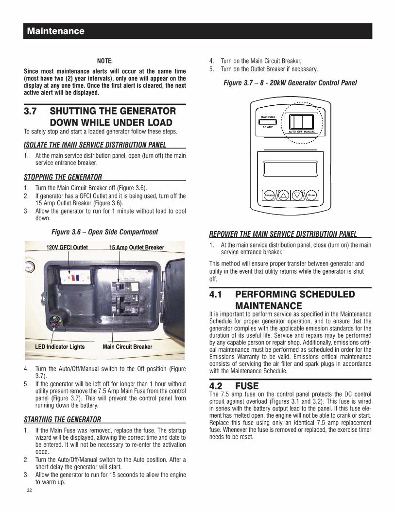
4. Turn the Auto/Off/Manual switch to the Off position (Figure 3.7).
5. If the generator will be left off for longer than 1 hour without utility present remove the 7.5 Amp Main Fuse from the control panel (Figure 3.7). This will prevent the control panel from running down the battery.
1. If the Main Fuse was removed, replace the fuse. The startup wizard will be displayed, allowing the correct time and date to be entered. It will not be necessary to re-enter the activation code.
2. Turn the Auto/Off/Manual switch to the Auto position. After a short delay the generator will start.
3. Allow the generator to run for 15 seconds to allow the engine to warm up.
4. Turn on the Main Circuit Breaker.5. Turn on the Outlet Breaker if necessary.
Figure 3.7 � 8 - 20kW Generator Control Panel
1. At the main service distribution panel, close (turn on) the main service entrance breaker.
This method will ensure proper transfer between generator and utility in the event that utility returns while the generator is shut off.
It is important to perform service as specified in the Maintenance Schedule for proper generator operation, and to ensure that the generator complies with the applicable emission standards for the duration of its useful life. Service and repairs may be performed by any capable person or repair shop. Additionally, emissions criti-cal maintenance must be performed as scheduled in order for the Emissions Warranty to be valid. Emissions critical maintenance consists of servicing the air filter and spark plugs in accordance with the Maintenance Schedule.
The 7.5 amp fuse on the control panel protects the DC control circuit against overload (Figures 3.1 and 3.2). This fuse is wired in series with the battery output lead to the panel. If this fuse ele-ment has melted open, the engine will not be able to crank or start. Replace this fuse using only an identical 7.5 amp replacement fuse. Whenever the fuse is removed or replaced, the exercise timer needs to be reset.
Maintenance
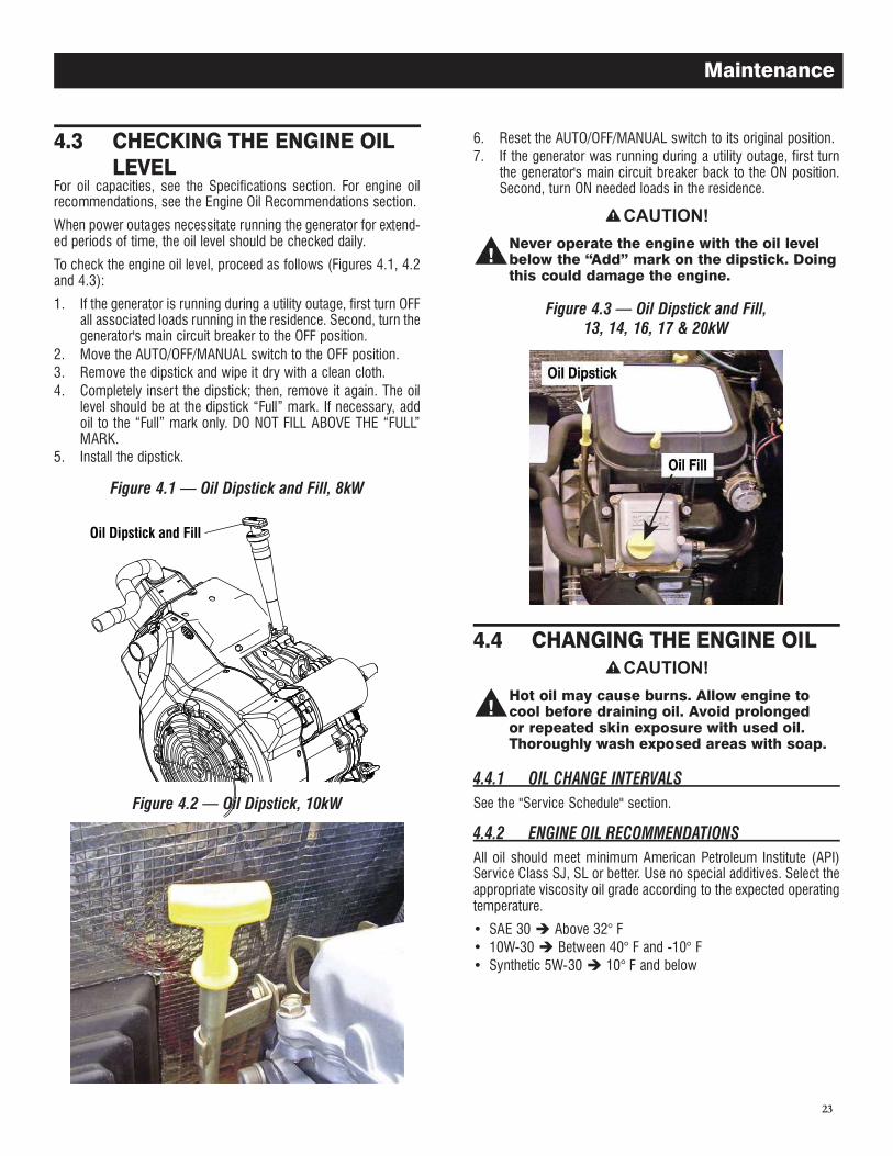
For oil capacities, see the Specifications section. For engine oil recommendations, see the Engine Oil Recommendations section.
When power outages necessitate running the generator for extend-ed periods of time, the oil level should be checked daily.
To check the engine oil level, proceed as follows (Figures 4.1, 4.2 and 4.3):
1. If the generator is running during a utility outage, first turn OFF all associated loads running in the residence. Second, turn the generator's main circuit breaker to the OFF position.
2. Move the AUTO/OFF/MANUAL switch to the OFF position.3. Remove the dipstick and wipe it dry with a clean cloth.4. Completely insert the dipstick; then, remove it again. The oil
level should be at the dipstick “Full” mark. If necessary, add oil to the “Full” mark only. DO NOT FILL ABOVE THE “FULL” MARK.
5. Install the dipstick.
Figure 4.1 � Oil Dipstick and Fill, 8kW
Oil Dipstick and Fill
Figure 4.2 � Oil Dipstick, 10kW
6. Reset the AUTO/OFF/MANUAL switch to its original position.7. If the generator was running during a utility outage, first turn
the generator's main circuit breaker back to the ON position. Second, turn ON needed loads in the residence.
Never operate the engine with the oil level below the “Add” mark on the dipstick. Doing this could damage the engine.
Figure 4.3 � Oil Dipstick and Fill, 13, 14, 16, 17 & 20kW
Hot oil may cause burns. Allow engine to cool before draining oil. Avoid prolonged or repeated skin exposure with used oil. Thoroughly wash exposed areas with soap.
See the "Service Schedule" section.
All oil should meet minimum American Petroleum Institute (API) Service Class SJ, SL or better. Use no special additives. Select the appropriate viscosity oil grade according to the expected operating temperature.
• SAE 30 Above 32° F• 10W-30 Between 40° F and -10° F• Synthetic 5W-30 10° F and below
23
Maintenance
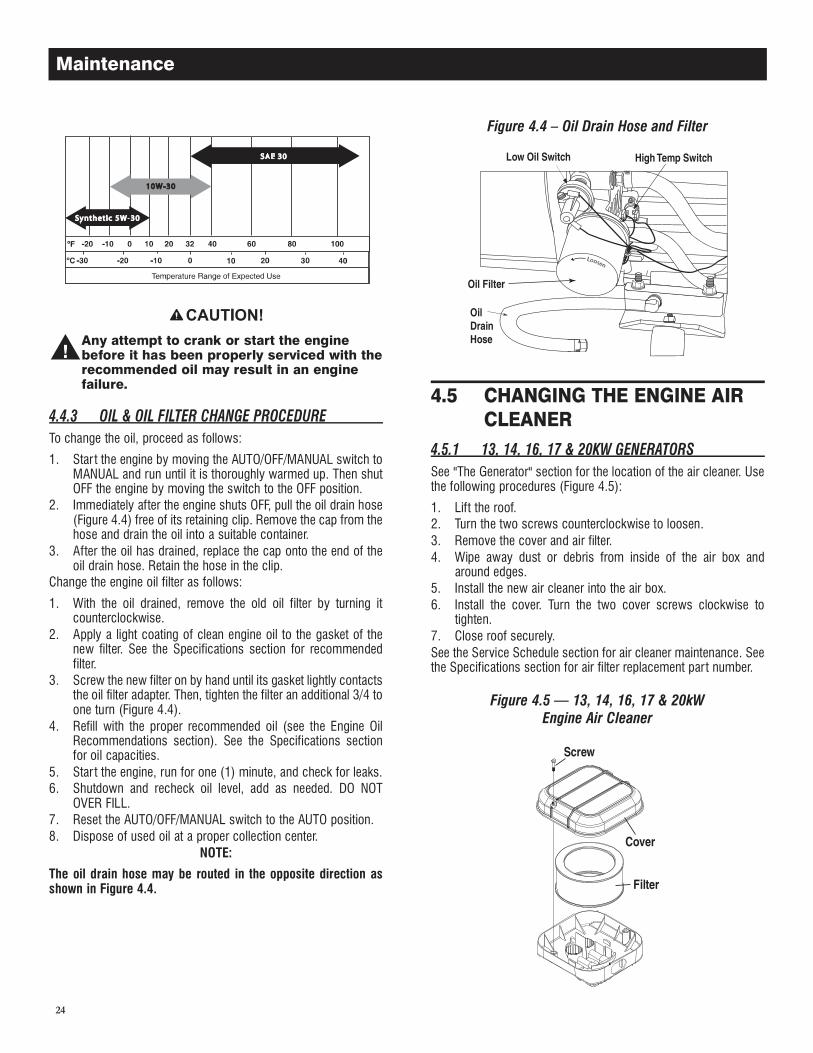
24
Any attempt to crank or start the engine before it has been properly serviced with the recommended oil may result in an engine failure.
To change the oil, proceed as follows:
1. Star t the engine by moving the AUTO/OFF/MANUAL switch to MANUAL and run until it is thoroughly warmed up. Then shut OFF the engine by moving the switch to the OFF position.
2. Immediately after the engine shuts OFF, pull the oil drain hose (Figure 4.4) free of its retaining clip. Remove the cap from the hose and drain the oil into a suitable container.
3. After the oil has drained, replace the cap onto the end of the oil drain hose. Retain the hose in the clip.
Change the engine oil filter as follows:
1. With the oil drained, remove the old oil filter by turning it counterclockwise.
2. Apply a light coating of clean engine oil to the gasket of the new filter. See the Specifications section for recommended filter.
3. Screw the new filter on by hand until its gasket lightly contacts the oil filter adapter. Then, tighten the filter an additional 3/4 to one turn (Figure 4.4).
4. Refill with the proper recommended oil (see the Engine Oil Recommendations section). See the Specifications section for oil capacities.
5. Star t the engine, run for one (1) minute, and check for leaks.6. Shutdown and recheck oil level, add as needed. DO NOT
OVER FILL.7. Reset the AUTO/OFF/MANUAL switch to the AUTO position.8. Dispose of used oil at a proper collection center.
NOTE:
The oil drain hose may be routed in the opposite direction as shown in Figure 4.4.
Figure 4.4 � Oil Drain Hose and Filter
See "The Generator" section for the location of the air cleaner. Use the following procedures (Figure 4.5):
1. Lift the roof.2. Turn the two screws counterclockwise to loosen.3. Remove the cover and air filter.4. Wipe away dust or debris from inside of the air box and
around edges.5. Install the new air cleaner into the air box.6. Install the cover. Turn the two cover screws clockwise to
tighten.7. Close roof securely.See the Service Schedule section for air cleaner maintenance. See the Specifications section for air filter replacement part number.
Figure 4.5 � 13, 14, 16, 17 & 20kWEngine Air Cleaner
Maintenance
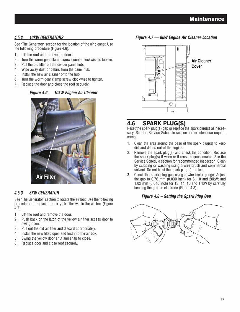
25
See "The Generator" section for the location of the air cleaner. Use the following procedure (Figure 4.6):
1. Lift the roof and remove the door.2. Turn the worm gear clamp screw counterclockwise to loosen.3. Pull the old filter off the divider panel hub.4. Wipe away dust or debris from the panel hub.5. Install the new air cleaner onto the hub.6. Turn the worm gear clamp screw clockwise to tighten.7. Replace the door and close the roof securely.
Figure 4.6 � 10kW Engine Air Cleaner
See "The Generator" section to locate the air box. Use the following procedures to replace the dir ty air filter within the air box (Figure 4.7).
1. Lift the roof and remove the door.2. Push back on the latch of the yellow air filter access door to
swing open.3. Pull out the old air filter and discard appropriately.4. Install the new filter, open end first into the air box.5. Swing the yellow door shut and snap to close.6. Replace door and close roof securely.
Figure 4.7 � 8kW Engine Air Cleaner Location
Reset the spark plug(s) gap or replace the spark plug(s) as neces-sary. See the Service Schedule section for maintenance require-ments.
1. Clean the area around the base of the spark plug(s) to keep dir t and debris out of the engine.
2. Remove the spark plug(s) and check the condition. Replace the spark plug(s) if worn or if reuse is questionable. See the Service Schedule section for recommended inspection. Clean by scraping or washing using a wire brush and commercial solvent. Do not blast the spark plug(s) to clean.
3. Check the spark plug gap using a wire feeler gauge. Adjust the gap to 0.76 mm (0.030 inch) for 8, 10 and 20kW; and 1.02 mm (0.040 inch) for 13, 14, 16 and 17kW by carefully bending the ground electrode (Figure 4.8).
Figure 4.8 � Setting the Spark Plug Gap
Maintenance
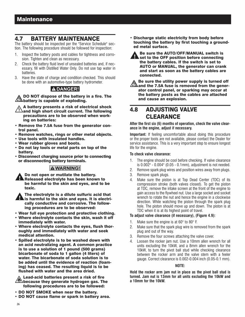
26
The battery should be inspected per the "Service Schedule" sec-tion. The following procedure should be followed for inspection:
1. Inspect the battery posts and cables for tightness and corro-sion. Tighten and clean as necessary.
2. Check the battery fluid level of unsealed batteries and, if nec-essary, fill with Distilled Water Only. Do not use tap water in batteries.
3. Have the state of charge and condition checked. This should be done with an automotive-type battery hydrometer.
DO NOT dispose of the battery in a fire. The battery is capable of exploding.
A battery presents a risk of electrical shock and high short circuit current. The following precautions are to be observed when work-ing on batteries:
• Remove the 7.5A fuse from the generator con-trol panel.
• Remove watches, rings or other metal objects.• Use tools with insulated handles.• Wear rubber gloves and boots.• Do not lay tools or metal parts on top of the
battery.• Disconnect charging source prior to connecting
or disconnecting battery terminals.
Do not open or mutilate the battery. Released electrolyte has been known to be harmful to the skin and eyes, and to be toxic.
The electrolyte is a dilute sulfuric acid that is harmful to the skin and eyes. It is electri-cally conductive and corrosive. The follow-ing procedures are to be observed:
• Wear full eye protection and protective clothing.• Where electrolyte contacts the skin, wash it off
immediately with water.• Where electrolyte contacts the eyes, flush thor-
oughly and immediately with water and seek medical attention.
• Spilled electrolyte is to be washed down with an acid neutralizing agent. A common practice is to use a solution of 1 pound (500 grams) bicarbonate of soda to 1 gallon (4 liters) of water. The bicarbonate of soda solution is to be added until the evidence of reaction (foam-ing) has ceased. The resulting liquid is to be flushed with water and the area dried.
Lead-acid batteries present a risk of fire because they generate hydrogen gas. The following procedures are to be followed:
• DO NOT SMOKE when near the battery.• DO NOT cause flame or spark in battery area.
• Discharge static electricity from body before touching the battery by first touching a ground-ed metal surface.
Be sure the AUTO/OFF/MANUAL switch is set to the OFF position before connecting the battery cables. If the switch is set to AUTO or MANUAL, the generator can crank and start as soon as the battery cables are connected.
Be sure the utility power supply is turned off and the 7.5A fuse is removed from the gener-ator control panel, or sparking may occur at the battery posts as the cables are attached and cause an explosion.
After the first six (6) months of operation, check the valve clear-ance in the engine, adjust if necessary.
Important: If feeling uncomfortable about doing this procedure or the proper tools are not available, please contact the Dealer for service assistance. This is a very important step to ensure longest life for the engine.
To check valve clearance:
1. The engine should be cool before checking. If valve clearance is 0.002" - 0.004" (0.05 - 0.1mm), adjustment is not needed.
2. Remove spark plug wires and position wires away from plugs.3. Remove spark plugs.4. Make sure the piston is at Top Dead Center (TDC) of its
compression stroke (both valves closed). To get the piston at TDC, remove the intake screen at the front of the engine to gain access to the flywheel nut. Use a large socket and socket wrench to rotate the nut and hence the engine in a clockwise direction. While watching the piston through the spark plug hole. The piston should move up and down. The piston is at TDC when it is at its highest point of travel.
To adjust valve clearance (if necessary), (Figure 4.9):
1. Make sure the engine is at 60° to 80° F.2. Make sure that the spark plug wire is removed from the spark
plug and out of the way.3. Remove the four screws attaching the valve cover.4. Loosen the rocker jam nut. Use a 10mm allen wrench for all
units excluding the 10kW, and a 8mm allen wrench for the 10kW, to turn the pivot ball stud while checking clearance between the rocker arm and the valve stem with a feeler gauge. Correct clearance is 0.002-0.004 inch (0.05-0.1 mm).
NOTE:
Hold the rocker arm jam nut in place as the pivot ball stud is turned. Jam nut is 13mm for all units excluding the 10kW and a 10mm for the 10kW.
Maintenance
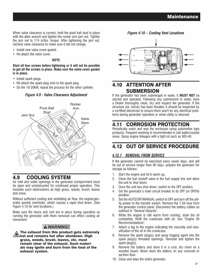
27
When valve clearance is correct, hold the pivot ball stud in place with the allen wrench and tighten the rocker arm jam nut. Tighten the jam nut to 174 in/lbs. torque. After tightening the jam nut, recheck valve clearance to make sure it did not change.
• Install new valve cover gasket.• Re-attach the valve cover.
NOTE:
Start all four screws before tightening or it will not be possible to get all the screws in place. Make sure the valve cover gasket is in place.
• Install spark plugs.• Re-attach the spark plug wire to the spark plug.• On the 10-20kW, repeat the process for the other cylinder.
Figure 4.9 - Valve Clearance Adjustment
Air inlet and outlet openings in the generator compartment must be open and unobstructed for continued proper operation. This includes such obstructions as high grass, weeds, brush, leaves and snow.
Without sufficient cooling and ventilating air flow, the engine/gen-erator quickly overheats, which causes a rapid shut down. (See Figure 4.10 for vent locations.)
Make sure the doors and roof are in place during operation as running the generator with them removed can effect cooling air movement.
The exhaust from this product gets extremely hot and remains hot after shutdown. High grass, weeds, brush, leaves, etc. must remain clear of the exhaust. Such materi-als may ignite and burn from the heat of the exhaust system.
Figure 4.10 � Cooling Vent Locations
If the generator has been submerged in water, it MUST NOT be started and operated. Following any submersion in water, have a Dealer thoroughly clean, dry and inspect the generator. If the structure (ex. home) has been flooded, it should be inspected by a certified electrician to ensure there won't be any electrical prob-lems during generator operation or when utility is returned.
Periodically wash and wax the enclosure using automotive type products. Frequent washing is recommended in salt water/coastal areas. Spray engine linkages with a light oil such as WD-40.
If the generator cannot be exercised every seven days, and will be out of service longer than 90 days, prepare the generator for storage as follows:
1. Star t the engine and let it warm up.2. Close the fuel shutoff valve in the fuel supply line and allow
the unit to shut down.3. Once the unit has shut down, switch to the OFF position.4. Set the generator’s main circuit breaker to its OFF (or OPEN)
position.5. Set the AUTO/OFF/MANUAL switch to OFF and turn off the util-
ity power to the transfer switch. Remove the 7.5A fuse from the generator control panel. Disconnect the battery cables as outlined in “General Hazards”.
6. While the engine is still warm from running, drain the oil completely. Refill the crankcase with oil. See ”Engine Oil Recommendations".
7. Attach a tag to the engine indicating the viscosity and clas-sification of the oil in the crankcase.
8. Remove the spark plug(s) and spray fogging agent into the spark plug(s) threaded openings. Reinstall and tighten the spark plug(s).
9. Remove the battery and store it in a cool, dry room on a wooden board. Never store the battery on any concrete or earthen floor.
10. Clean and wipe the entire generator.
Maintenance
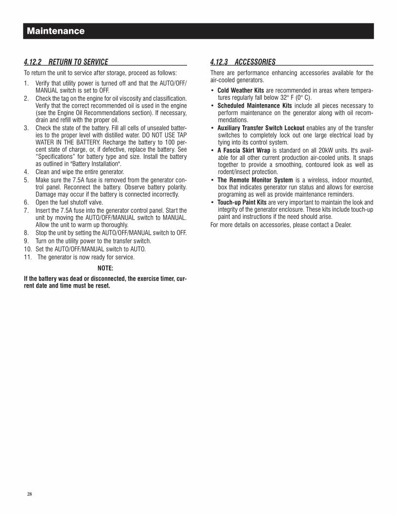
28
To return the unit to service after storage, proceed as follows:
1. Verify that utility power is turned off and that the AUTO/OFF/MANUAL switch is set to OFF.
2. Check the tag on the engine for oil viscosity and classification. Verify that the correct recommended oil is used in the engine (see the Engine Oil Recommendations section). If necessary, drain and refill with the proper oil.
3. Check the state of the battery. Fill all cells of unsealed batter-ies to the proper level with distilled water. DO NOT USE TAP WATER IN THE BATTERY. Recharge the battery to 100 per-cent state of charge, or, if defective, replace the battery. See “Specifications” for battery type and size. Install the battery as outlined in "Battery Installation".
4. Clean and wipe the entire generator.5. Make sure the 7.5A fuse is removed from the generator con-
trol panel. Reconnect the battery. Observe battery polarity. Damage may occur if the battery is connected incorrectly.
6. Open the fuel shutoff valve.7. Insert the 7.5A fuse into the generator control panel. Start the
unit by moving the AUTO/OFF/MANUAL switch to MANUAL. Allow the unit to warm up thoroughly.
8. Stop the unit by setting the AUTO/OFF/MANUAL switch to OFF.9. Turn on the utility power to the transfer switch.10. Set the AUTO/OFF/MANUAL switch to AUTO.11. The generator is now ready for service.
NOTE:
If the battery was dead or disconnected, the exercise timer, cur-rent date and time must be reset.
There are performance enhancing accessories available for the air-cooled generators.
• Cold Weather Kits are recommended in areas where tempera-tures regularly fall below 32° F (0° C).
• Scheduled Maintenance Kits include all pieces necessary to perform maintenance on the generator along with oil recom-mendations.
• Auxiliary Transfer Switch Lockout enables any of the transfer switches to completely lock out one large electrical load by tying into its control system.
• A Fascia Skirt Wrap is standard on all 20kW units. It's avail-able for all other current production air-cooled units. It snaps together to provide a smoothing, contoured look as well as rodent/insect protection.
• The Remote Monitor System is a wireless, indoor mounted, box that indicates generator run status and allows for exercise programing as well as provide maintenance reminders.
• Touch-up Paint Kits are very important to maintain the look and integrity of the generator enclosure. These kits include touch-up paint and instructions if the need should arise.
For more details on accessories, please contact a Dealer.
Maintenance
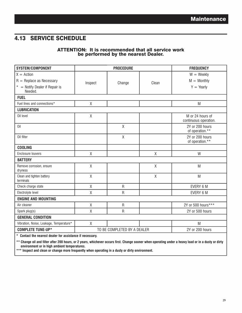
29
ATTENTION: It is recommended that all service work be performed by the nearest Dealer.
SYSTEM/COMPONENT PROCEDURE FREQUENCY
X = Action
R = Replace as Necessary
* = Notify Dealer if Repair is Needed.
Inspect Change Clean
W = Weekly
M = Monthly
Y = Yearly
FUEL Fuel lines and connections* X M
LUBRICATION Oil level X M or 24 hours of
continuous operation. Oil X 2Y or 200 hours
of operation.** Oil filter X 2Y or 200 hours
of operation.**
COOLING Enclosure louvers X X W
BATTERY
Remove corrosion, ensure dryness
X X M
Clean and tighten battery terminals
X X M
Check charge state X R EVERY 6 M Electrolyte level X R EVERY 6 M
ENGINE AND MOUNTING Air cleaner X R 2Y or 500 hours*** Spark plug(s) X R 2Y or 500 hours
GENERAL CONDITION Vibration, Noise, Leakage, Temperature* X M
COMPLETE TUNE-UP* TO BE COMPLETED BY A DEALER 2Y or 200 hours
* Contact the nearest dealer for assistance if necessary.
** Change oil and filter after 200 hours, or 2 years, whichever occurs first. Change sooner when operating under a heavy load or in a dusty or dirty environment or in high ambient temperatures.
*** Inspect and clean or change more frequently when operating in a dusty or dirty environment.
Maintenance
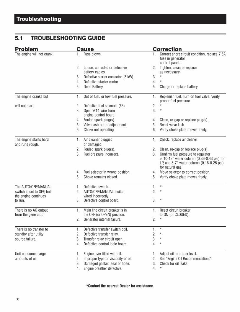
30
Troubleshooting
Problem Cause CorrectionThe engine will not crank. 1. Fuse blown. 1. Correct short circuit condition, replace 7.5A
fuse in generator control panel.
2. Loose, corroded or defective 2. Tighten, clean or replace battery cables. as necessary. 3. Defective starter contactor. (8 kW) 3. * 4. Defective starter motor. 4. * 5. Dead Battery. 5. Charge or replace battery.
The engine cranks but 1. Out of fuel, or low fuel pressure. 1. Replenish fuel. Turn on fuel valve. Verify proper fuel pressure.
will not start. 2. Defective fuel solenoid (FS). 2. * 3. Open #14 wire from 3. *
engine control board. 4. Fouled spark plug(s). 4. Clean, re-gap or replace plug(s). 5. Valve lash out of adjustment. 5. Reset valve lash. 6. Choke not operating. 6. Verify choke plate moves freely.
The engine star ts hard 1. Air cleaner plugged 1. Check, replace air cleaner.and runs rough. or damaged. 2. Fouled spark plug(s). 2. Clean, re-gap or replace plug(s). 3. Fuel pressure incorrect. 3. Confirm fuel pressure to regulator
is 10-12” water column (0.36-0.43 psi) for LP, and 5-7” water column (0.18-0.25 psi) for natural gas.
4. Fuel selector in wrong position. 4. Move selector to correct position. 5. Choke remains closed. 5. Verify choke plate moves freely.
The AUTO/OFF/MANUAL 1. Defective switch. 1. *switch is set to OFF, but 2. AUTO/OFF/MANUAL switch 2. *the engine continues wired incorrectly.to run. 3. Defective control board. 3. *
There is no AC output 1. Main line circuit breaker is in 1. Reset circuit breaker from the generator. the OFF (or OPEN) position. to ON (or CLOSED). 2. Generator internal failure. 2. *
There is no transfer to 1. Defective transfer switch coil. 1. *standby after utility 2. Defective transfer relay. 2. *source failure. 3. Transfer relay circuit open. 3. * 4. Defective control logic board. 4. *
Unit consumes large 1. Engine over filled with oil. 1. Adjust oil to proper level.amounts of oil. 2. Improper type or viscosity of oil. 2. See "Engine Oil Recommendations". 3. Damaged gasket, seal or hose. 3. Check for oil leaks. 4. Engine breather defective. 4. *
*Contact the nearest Dealer for assistance.
31
To get to the MENU, use the "Esc" key from any page. It may need to be pressed many times before getting to the menu page. The currently selected menu is displayed as a flashing word. Navigate to the menu required by using the +/- keys. When the menu required is flashing, press the ENTER key. Depending on the menu selected, there may be a list of choices presented. Use the same navigation method to select the the desired screen (refer to the Menu System diagram).
To change a setting such as display contrast, go to the EDIT menu and use the +/- keys to navigate to the setting to change. Once this setting is displayed (e.g. Contrast), press the ENTER key to go into the edit mode. Use the +/- keys to change the setting, press the ENTER key to store the new setting.
NOTE:
If the ENTER key is not pressed to save the new setting, it will only be saved temporarily. The next time the battery is discon-nected, the setting will revert back to the previous setting.
Appendix
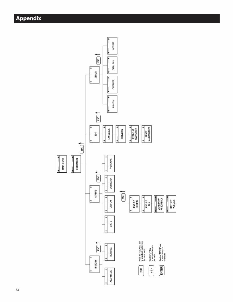
32
Appendix
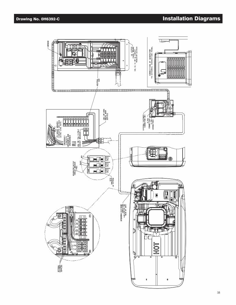
33
Drawing No. 0H6392-C Installation Diagrams
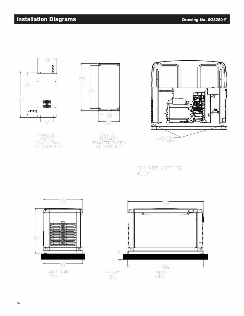
34
Installation Diagrams Drawing No. 0G8280-F
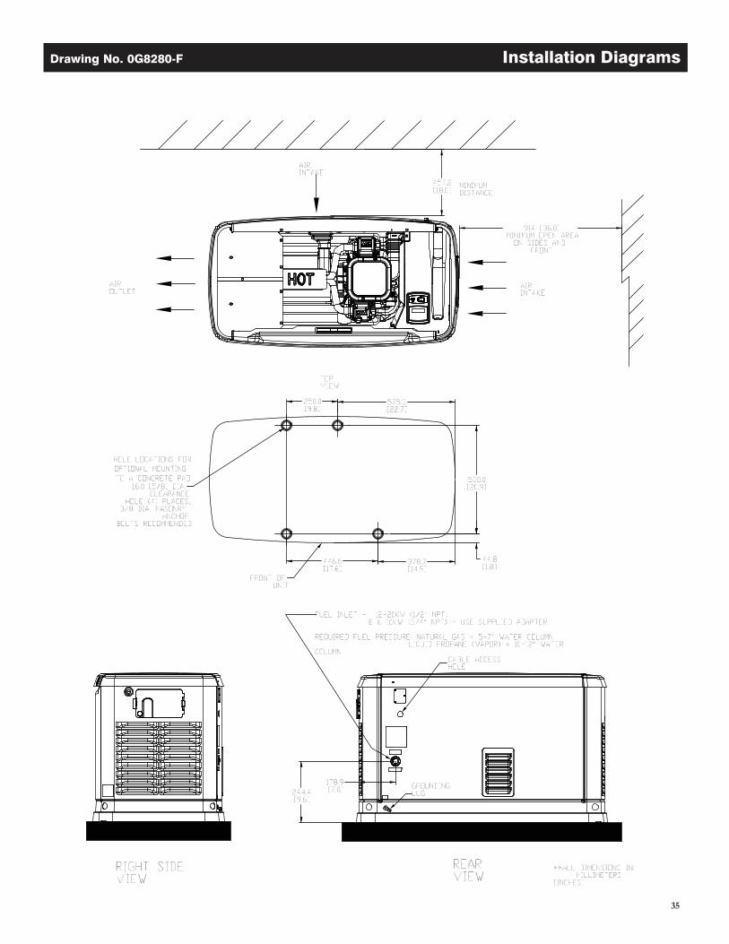
35
Drawing No. 0G8280-F Installation Diagrams
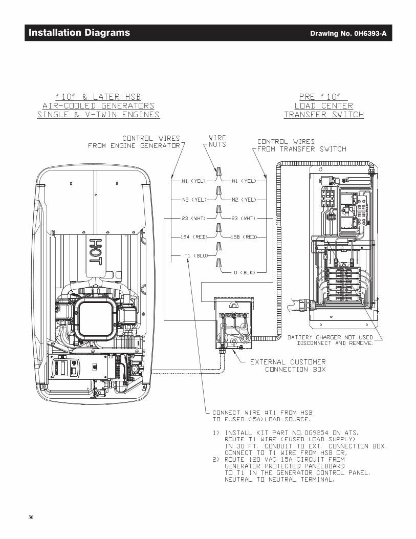
36
Installation Diagrams Drawing No. 0H6393-A
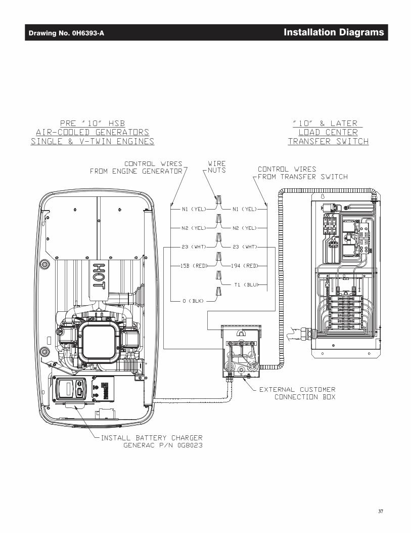
37
Drawing No. 0H6393-A Installation Diagrams
38
Warranty
U.S. EPA EMISSION CONTROL WARRANTY STATEMENTYOUR WARRANTY RIGHTS AND OBLIGATIONS
The United States Environmental Protection Agency (EPA) and Generac Power Systems, Inc. (Generac) are pleased to explain the Emission Control System Warranty (ECS Warranty) on your new 2011 and later equipment. New equipment that use small spark-ignited engines must be designed, built, and equipped to meet stringent anti-smog standards for the federal government. Generac will warrant the emission control system on your equipment for the period of time listed below provided there has been no abuse, neglect, unapproved modification or improper maintenance of your equipment.The emission control system on this equipment includes all components whose failure would increase the emissions of any regulated pollutant. These components are listed in the Emissions Information section of this manual.
MANUFACTURER’S WARRANTY COVERAGE:This ECS Warranty is valid for two years, or for the same period as specified in the Generac Limited Warranty, whichever is longer. For equipment with hour meters, the warranty period is a number of hours equal to half the Useful Life to which the equipment is cer tified, or the warranty period specified above in years, whichever is less. The Useful Life can be found on the Emission Control Label on the engine. If, during such warranty period, any emission-related part on your equipment is found to be defective in materials or workmanship, repairs or replacement will be performed by a Generac Authorized Warranty Service Dealer.
OWNER'S WARRANTY RESPONSIBILITIES:As the equipment owner, you are responsible for the completion of all required maintenance as listed in your factory supplied Owner's Manual. For warranty purposes, Generac recommends that you retain all receipts covering maintenance on your generator, but Generac cannot deny warranty solely due to the lack of receipts.
You should be aware that Generac may deny any and/or all warranty coverage or responsibility if your equipment, or a part/component thereof, has failed due to abuse, neglect, improper maintenance, or unapproved modifications.
You are responsible for contacting a Generac Authorized Warranty Dealer as soon as a problem occurs. The warranty repairs should be completed in a reasonable amount of time, not to exceed 30 days.
Warranty service can be arranged by contacting either your selling dealer or a Generac Authorized Warranty Service Dealer. To locate the Generac Authorized Warranty Service Dealer nearest you, call our toll free number below, or email [email protected].
1-800-333-1322IMPORTANT NOTE: This warranty statement explains your rights and obligations under the Emission Control System Warranty, which is provided to you by Generac pursuant to federal law. See also the "Generac Limited Warranties for Generac Power Systems, Inc.," which is enclosed herewith on a separate sheet, also provided to you by Generac. Note that this warranty shall not apply to any incidental, consequential or indirect damages caused by defects in materials or workmanship or any delay in repair or replacement of the defective part(s). This warranty is in place of all other warranties, expressed or implied. Specifically, Generac makes no other warranties as to the merchantability or fitness for a particular purpose. Any implied warranties which are allowed by law, shall be limited in duration to the terms of the express warranty provided herein. Some states do not allow limitations on how long an implied warranty lasts, so the above limitation may not apply to you.
The ECS Warranty applies only to the emission control system of your new equipment. Both the ECS Warranty and the Generac Warranty describe important rights and obligations with respect to your new engine.
Warranty service can be performed only by a Generac Authorized Warranty Service Facility. When requesting warranty service, evidence must be presented showing the date of the sale to the original purchaser/owner.
If you have any questions regarding your warranty rights and responsibilities, you should contact Generac at the following address:
ATTENTION WARRANTY DEPARTMENTGENERAC POWER SYSTEMS, INC.
P.O. BOX 297 • WHITEWATER, WI 53190
Part 1 of 2
Part No. 0J3335 Rev. C 11/11
39
Warranty
EMISSION CONTROL SYSTEM WARRANTYEmission Control System Warranty (ECS Warranty) for equipment using small spark-ignited engines:
(a) Applicability: This warranty shall apply to equipment that uses small off-road engines. The ECS Warranty period shall begin on the date the new equipment is purchased by/delivered to its original, end-use purchaser/owner and shall continue for the lesser of:
(1) The period of time specified in the Generac Limited Warranty enclosed herewith, but not less than 24 months, or (2) For engines equipped with hour meters, a number of operating hours equal to half of the engine’s useful life. The useful life is specified on the
Emissions Control Label on the engine.
(b) General Emissions Warranty Coverage: Generac warrants to the original, end-use purchaser/owner of the new engine or equipment and to each subsequent purchaser/owner that the ECS when installed was:
(1) Designed, built and equipped so as to conform with all applicable regulations; and (2) Free from defects in materials and workmanship which cause the failure of a warranted part at any time during the ECS Warranty Period.
(c) The warranty on emissions-related parts will be interpreted as follows: (1) Any warranted part that is not scheduled for replacement as required maintenance in the Owner's Manual shall be warranted for the ECS
Warranty Period. If any such part fails during the ECS Warranty Period, it shall be repaired or replaced by Generac according to Subsection (4) below. Any such part repaired or replaced under the ECS Warranty shall be warranted for the remainder of the ECS Warranty Period.
(2) Any warranted part that is scheduled only for regular inspection as specified in the Owner's Manual shall be warranted for the ECS Warranty Period. A statement in the Owner’s Manual to the effect of "repair or replace as necessary" shall not reduce the ECS Warranty Period. Any such part repaired or replaced under the ECS Warranty shall be warranted for the remainder of the ECS Warranty Period.
(3) Any warranted part that is scheduled for replacement as required maintenance in the Owner's Manual shall be warranted for the period of time prior to first scheduled replacement point for that part. If the part fails prior to the first scheduled replacement, the part shall be repaired or replaced by Generac according to Subsection (4) below. Any such emissions-related part repaired or replaced under the ECS warranty shall be warranted for the remainder of the period prior to the first scheduled replacement point for that part.
(4) Repair or replacement of any warranted, emissions-related part under this ECS Warranty shall be performed at no charge to the owner at a Generac Authorized Warranty Service Facility.
(5) Notwithstanding the provisions of subsection (4) above, warranty services or repairs must be provided at Generac Authorized Service Facilities.
(6) When the engine is inspected by a Generac Authorized Warranty Service Facility, the purchaser/owner shall not be held responsible for diagnostic costs if the repair is deemed warrantable.
(7) Throughout the ECS Warranty Period, Generac shall maintain a supply of warranted emission-related parts sufficient to meet the expected demand for such parts.
(8) Any Generac authorized and approved emission-related replacement parts may be used in the performance of any ECS Warranty maintenance or repairs and will be provided without charge to the purchaser/owner. Such use shall not reduce Generac’s ECS Warranty obligations.
(9) No modifications, other than those explicitly approved by Generac, may be made to the generator. Unapproved modifications void this ECS Warranty and shall be sufficient ground for disallowing an ECS Warranty claim.
(10) Generac shall not be held liable hereunder for failures of any non-authorized replacement parts, or failures of any authorized parts caused by the use of non-authorized replacement parts.
EMISSION RELATED PARTS MAY INCLUDE THE FOLLOWING (IF EQUIPPED):
1) FUEL METERING SYSTEM A. CARBURETOR AND INTERNAL PARTS B. FUEL TANK/CAP C. FUEL LINES D. EVAPORATIVE VENT LINES E. REGULATOR (GASEOUS FUELS)2) AIR INDUCTION SYSTEM A. INTAKE MANIFOLD B. AIR FILTER
3) IGNITION SYSTEM A. SPARK PLUGS B. IGNITION COILS/MODULE4) AIR INJECTION SYSTEM A. PULSE AIR VALVE5) EXHAUST SYSTEM A. CATALYST B. EXHAUST MANIFOLD
Part 2 of 2
Part No. 0J3335 Rev. C 11/11
40
Warranty
United States Environmental Protection Agency Warranty Statement(Stationary Emergency Spark-Ignited Generators)
Warranty Rights, Obligations and Coverage
The United States Environmental Protection Agency (EPA) and Generac Power Systems, Inc. (Generac) are pleased to explain the Emission Control System Warranty on your new stationary emergency engine. If during the warranty period, any emission control system or component on your engine is found defective in materials or workmanship, Generac will repair your engine at no cost to you for diagnosis, replacement parts and labor provided it be done by a Generac Authorized Warranty Service Facility. Your emission control system may include parts such as the fuel metering, ignition, and exhaust systems and other related emission related components listed below. Generac will warrant the emissions control systems on your 2009 and later model year engines provided there has been no abuse, neglect, unapproved modification or improper maintenance of your engine. For engines less than 130 HP the warranty period is two years from the date of sale to the ultimate purchaser. For engines greater than or equal to 130 HP the warranty period is three years from the date of the engine being placed into service.
Purchaser’s/Owner’s Warranty ResponsibilitiesAs the engine purchaser/owner you are responsible for the following. 1.) The engine must be installed and configured in accordance to the Generac’s installation specifications. 2.) The completion of all maintenance requirements listed in your Owner’s Manual. 3.) Any engine setting adjustment must be done in accordance and consistent with the instructions in the Owner’s Manual. 4.) Any emission control system or component must be maintained and operated appropriately in order to ensure proper operation of the engine and control system to minimize emissions at all times.
Generac may deny any/or all Emission Control System Warranty coverage or responsibility of the engine, or an emission control system or component on your engine thereof, if it has failed due to abuse, neglect, unapproved modification or improper maintenance, or the use of counterfeit and/or ‘gray market’ parts not made, supplied or approved by Generac. Warranty service can be arranged by contacting either your selling dealer or a Generac Authorized Warranty Service dealer, 1-800-333-1322 for the dealer nearest you. The purchaser/owner shall be responsible for any expenses or other charges incurred for service calls and/or transportation of the product to/from the inspection or repair facilities. The purchaser/owner shall be responsible for any and/or all damages or losses incurred while the engine is being transported/shipped for inspection or warranty repairs. Contact Generac Power Systems Inc. for additional Emission Control System Warranty related information, Generac Power Systems, Inc. P.O. Box 8, Waukesha, WI 53187, or call 1-800-333-1322 or www.generac.com.
Important Note: This warranty statement explains your rights and obligations under the Emission Control System Warranty, which is provided to you by Generac pursuant to federal law. Note that this warranty shall not apply to any incidental, consequential or indirect damages caused by defects in materials or workmanship or any delay in repair or replacement of the defective part(s). This warranty is in place of all other warranties, expressed or implied. Specifically, Generac makes no other warranties as to the merchantability or fitness for a particular purpose. Any implied warranties which are allowed by law, shall be limited in duration to the terms of the express warranty provided herein. Some states do not allow limitations on how long an implied warranty lasts, so the above limitation may not apply to you.
Emission Related Parts Include the Following (if so equipped)
1) Fuel Metering System1.1) Gasoline Carburetor Assembly And Internal Components
A) Fuel Filter, B) Carburetor, C) Fuel Pump1.2) Carburetion Assembly And Its Components
A) Fuel Controller, B) Carburetor And Its Gaskets, C) Mixer And It Gaskets, D) Primary Gas Regulator E) Liquid Vaporizer
1.3) Fuel Regulator2) Air Induction System Including A) Intake Pipe/Manifold, B) Air Cleaner
3) Ignition System Including A) Spark Plug, B) Ignition Module, C) Ignition Coil, D) Spark Plug Wires4) Exhaust System A) Catalyst Assembly, B) Exhaust Manifold, C) Muffler, D) Exhaust Pipe, E) Muffler Gasket5) Crankcase Breather Assembly Including A) Breather Connection Tube, B) Pcv Valve6) Oxygen Sensor7) Diagnostic Emission-Control System
Part 1 of 2
Part No. 0H1916 Rev. C 11/11
41
Warranty
United States Environmental Protection Agency Compliance Requirements
(Stationary Emergency Spark-Ignited Generators)
Purchaser’s/Owner’s Recordkeeping Responsibilities
The United States Environmental Protection Agency (EPA) and Generac Power Systems, Inc. (Generac) are pleased to explain your recordkeeping requirements for compliance with Subpart JJJJ- Standards of Performance for Stationary Spark Ignition Internal Combustion Engines as listed in the Electronic Code of Federal Regulations Title 40 Part 60. As the engine purchaser/owner who operates and maintains their certified emergency stationary engine and emission control system according to applicable emission related guidelines as specified in this Owner’s Manual, you are required to meet the following notification and recordkeeping requirements to demonstrate compliance. 1.) Maintain documentation that the engine is certified to meet emission standards. 2.) Recordkeeping of maintenance conducted. 3.) Recordkeeping of the provision allowing natural gas engines to operate using propane for a maximum of 100 hours per year as an alternate fuel solely during emergency operations provided the engine is not certified to operate on propane. 4.) Meet all compliance notifications submitted to the purchaser/owner and maintain all supporting documentation. 5.) Recordkeeping of hours of operation, including what classified the operation as emergency and how many hours are spent for non-emergency operation. For emergency engines greater than or equal to 130 HP, recordkeeping of hours of operation begins January 1, 2011. For emergency engines less than 130 HP, recordkeeping of hours of operation begins January 1, 2009; Engines are equipped with non-resettable hour meters to facilitate recordkeeping.
Specific Air Quality Management or Air Pollution Control Districts may have different and additional record keeping/reporting requirements. Your permit to construct and/or operate the engine may be contingent upon compliance with those requirements. Check with your local Air Quality Management or Air Pollution Control District for specific requirements.
Emergency stationary internal combustion engines (ICE) may be operated for the purpose of maintenance checks and readiness testing, provided that the tests are recommended by Federal, State or local government, Generac, or the insurance company associated with the engine. Mainte-nance checks and readiness testing of such units is limited to 100 hours per year. There is no time limit on the use of emergency stationary ICE in emergency situations. The purchaser/owner may petition the Administrator for approval of additional hours to be used for maintenance checks and readiness testing, but a petition is not required if the owner maintains records indicating that Federal, State, or local standards require maintenance and testing of emergency ICE beyond 100 hours per year. Emergency stationary ICE may operate up to 50 hours per year in non emergency situa-tions, but those 50 hours are counted towards the 100 hours per year provided for maintenance and testing.
The 50 hours per year for non-emergency situations cannot be used for peak shaving or to generate income for a facility to supply power to an electric grid or otherwise supply power as part of a financial arrangement with another entity. For purchaser/owner of emergency engines, any operation other than emergency operation, maintenance and testing, and operation in non-emergency situations for 50 hours per year, as permitted in this section is prohibited.
If you operate and maintain your certified emergency stationary SI internal combustion engine and emissions control systems in accordance to the specifications and guidelines in this Owner’s Manual EPA will not require engine performance testing. If not, your engine will be considered non-certified and you must demonstrate compliance according to Subpart JJJJ - Standards of Performance for Stationary Spark Ignition Internal Combustion Engines as listed in the Electronic Code of Federal Regulations Title 40 Part 60.
Emission-Related Installation Instructions
Your certified emergency stationary engine has pre-set emission control systems or components that require no adjustment. Inspection and replacement of an emissions related component is required to be done so in accordance with the requirements cited in the United States Environ-mental Protection Agency Warranty Statement or can be arranged by contacting either your selling dealer or a Generac Authorized Warranty Ser-vice dealer, 1-800-333-1322 for the dealer nearest you. Failing to follow these instructions when installing a certified engine in a piece of nonroad equipment violates federal law 40 CFR 1068.105 (b), subject to fines or penalties as described in the Clean Air Act.
Part 2 of 2
Part No. 0H1916 Rev. C 11/11

Part No. 0J7632 Revision B (03/13/12) Printed in U.S.A.