Embed Size (px)
Citation preview

OWNERS MANUAL
Operation & Installation Instructions
LK5-A12, LK5-A22, LK5-A42, LK5-A62, LK6-A12, LK6-A22, LK6-A42, LK6-A62
LK5-A12-50, LK5-A22-50, LK5-A42-50, LK5-A62-50, LK6-A12-50, LK6-A22-50, LK6-A42-50, LK6-
A62-50
LK5-A12-HW, LK5-A22-HW, LK5-A42-HW, LK5-A62-HW, LK6-A12-HW, LK6-A22-HW, LK6-A42-
HW, LK6-A62-HW
LK5-A12-TOC, LK5-A22-TOC, LK5-A42-TOC, LK5-A62-TOC, LK6-A12-TOC, LK6-A22-TOC, LK6-
A42-TOC, LK6-A62-TOC
illuminating technologies for life
2 | P a g e
Congratulations on purchasing this ultraviolet disinfection system. By purchasing a LUMINOR UV
Disinfection system you are receiving not only a high quality product but also peace of mind. Protecting
your water supply with a UV system gives you reassurance that your family will have access to safe
drinking water throughout your entire home with no chance of microbiological contamination. This is
chemical free process which is simple in its concept and effective in its abilities to inactivate
microorganisms present in the water supply. Simple maintenance, continuous disinfection and
ultimately safe water, LUMINOR makes it that easy.
3 | P a g e
TABLE OF CONTENTS
SECTION 1 General Information ............................................................................................... 5
1.1 UV Disinfection Overview ............................................................................................... 5
1.1.1 Disinfection Process ................................................................................................ 5
1.1.2 Germicidal UV Light ................................................................................................ 5
1.1.3 WARNING: UV LIGHT .............................................................................................. 6
1.1.4 Concept of UV Dose ................................................................................................ 6
1.1.5 Key Water Quality Parameters Affecting UV Disinfection ...................................... 6
1.2 K2 System Overview ....................................................................................................... 8
1.2.1 Model Number ........................................................................................................ 8
1.2.2 Equipment List ........................................................................................................ 8
1.2.3 Operating Environment Limits ................................................................................ 8
1.2.4 General Specifications ............................................................................................ 9
1.3 Installation Guidelines .................................................................................................. 11
1.3.1 Reactor Dimensions and Clearances ..................................................................... 11
1.3.3 Reactor Installation, Piping, Leak-Test .................................................................. 13
1.3.4 WARNING: INITIAL WATER FLOW ......................................................................... 14
1.3.5 WARNING: WATER-HAMMER ............................................................................... 14
1.3.6 Electrical Panel Installation ................................................................................... 14
1.3.7 Reactor Cable Bundle and Ground Connection .................................................... 15
1.3.8 UV Sensor Cable Connection ................................................................................ 15
1.4 Warranty ....................................................................................................................... 16
1.5 Company Contact Information ..................................................................................... 18
SECTION 2 Operation, Control, Monitoring ............................................................................ 19
2.1 Overview: System Operation, Control, Monitoring ...................................................... 19
2.2 LCD Display Menu System ............................................................................................ 20
2.3 Mode Selection ............................................................................................................. 21
2.3.1 Local Mode ............................................................................................................ 21
2.3.2 Remote Mode ....................................................................................................... 21
2.4 Alarms ........................................................................................................................... 21
2.4.1 Alarm List with Function Details ........................................................................... 22
4 | P a g e
2.4.2 Control Board Output List ..................................................................................... 23
2.4.3 Remote Control Interface Wiring ......................................................................... 23
SECTION 3 Maintenance ......................................................................................................... 24
3.1 Routine Maintenance Chart .......................................................................................... 24
3.2 UV Lamp Disposal or Breakage ..................................................................................... 24
3.2.1 Safety Notes: ......................................................................................................... 24
3.2.2 Mercury Considerations for Amalgam Lamps: ..................................................... 24
3.2.3 Lamp Breaks Inside Reactor .................................................................................. 25
3.2.4 Lamp and Sleeve Break Inside Reactor ................................................................. 25
3.3 Lamp Installation / Removal ......................................................................................... 26
3.4 Lamp Change Interval ................................................................................................... 27
3.5 Sleeve Removal ............................................................................................................. 27
3.6 Manual Sleeve Cleaning ................................................................................................ 27
3.7 Sleeve Installation ......................................................................................................... 28
3.8 UV Sensor ...................................................................................................................... 28
3.8.1 UV Sensor Installation ........................................................................................... 28
3.8.2 UV Sensor Removal ............................................................................................... 29
3.8.3 UV Sensor Cleaning ............................................................................................... 29
3.9 Cooling Fans & Exhaust Filters ...................................................................................... 30
3.10 Common Replacement Parts ........................................................................................ 30
SECTION 4 Field Notes ............................................................................................................ 30
5 | P a g e
Section 1 General Information
1.1 UV Disinfection Overview
1.1.1 Disinfection Process
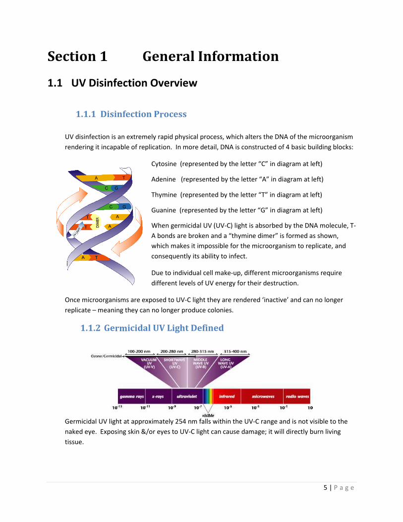
UV disinfection is an extremely rapid physical process, which alters the DNA of the microorganism
rendering it incapable of replication. In more detail, DNA is constructed of 4 basic building blocks:
Cytosine (represented by the letter “C” in diagram at left)
Adenine (represented by the letter “A” in diagram at left)
Thymine (represented by the letter “T” in diagram at left)
Guanine (represented by the letter “G” in diagram at left)
When germicidal UV (UV-C) light is absorbed by the DNA molecule, T-
A bonds are broken and a “thymine dimer” is formed as shown,
which makes it impossible for the microorganism to replicate, and
consequently its ability to infect.
Due to individual cell make-up, different microorganisms require
different levels of UV energy for their destruction.
Once microorganisms are exposed to UV-C light they are rendered ‘inactive’ and can no longer
replicate – meaning they can no longer produce colonies.
1.1.2 Germicidal UV Light Defined
Germicidal UV light at approximately 254 nm falls within the UV-C range and is not visible to the
naked eye. Exposing skin &/or eyes to UV-C light can cause damage; it will directly burn living
tissue.
6 | P a g e
1.1.3 WARNING: UV LIGHT
NEVER ALLOW SKIN OR EYES TO BE EXPOSED TO LIGHT
COMING FROM A GERMICIDAL UV LAMP AS TISSUE DAMAGE
WILL RESULT
1.1.4 Concept of UV Dose
The amount of UV energy delivered to a microorganism as it passes through a UV reactor is
commonly referred to as UV dose.
In a very simplistic model, UV Dose is the product of UV Intensity x Exposure Time
DOSE = (INTENSITY) X (TIME)
= millijoules / (sec)(cm2) X time
= mJ/cm2 (Note: 10 J/m
2 = 1,000 microWsec/cm
2 = 1 mJ/cm
2)
The degree of disinfection is dependent upon the UV dose received by the microorganisms in the
water, as well as the microorganism type’s UV sensitivity.
1.1.5 Key Water Quality Parameters Affecting UV Disinfection
Since the degree of disinfection is dependent in part upon the UV dose received by the
microorganisms in the water, it makes sense that any obstacles between the microorganism and
the UV light source will impede the disinfection process. In order for the germicidal UV light to
reach its DNA target, it must pass through several barriers, the three most significant being:
• Quartz sleeve; the sleeve protects the UV lamp from the water. If the outer surface of
the sleeve becomes fouled with deposits, the UV light will not reach the water. Water
“hardness” is one parameter that can greatly affect sleeve fouling. Note that in some
cases a fouled quartz sleeve may look perfectly clear to the eye: this happens as some
fouling deposits don’t affect visible light, but will severely absorb UV-C light.
• Second, germicidal UV light can be absorbed by compounds in the water, reducing the
amount of effective UV energy available to inactivate microorganisms. The key measure
is the water’s UV Transmittance (UVT), usually expressed as the percentage of 254 nm
UV light that passes through a 1 cm water path. Iron and tannin compounds are often
found to be problematic in reducing water’s UVT. Keep in mind that a water sample can
look perfectly clear to the naked eye, but still have a very low UVT at 254 nm: a proper
instrument is required to assess UVT at 254 nm.
7 | P a g e
• Third, turbidity has an effect on scattering of UV light, absorption and light penetration
within the water.
For the above reasons, LUMINOR recommends the following minimum water quality guidelines be
met for water flowing through the UV reactor.
• Iron: < 0.3 ppm (0.3 mg/L)
• Manganese: < 0.05 ppm (0.05 mg/L)
• Turbidity: < 1 NTU
• Hardness: < 7 gpg (120 mg/L)
• Tannins: < 0.1 ppm (0.1 mg/L)
Should the water quality be of a concern, please contact the factory or authorized representative.
UVT and some chemical analysis should always be done prior to specifying a UV disinfection
system.
8 | P a g e
1.2 K2 System Overview
1.2.1 Model Number
System Model Numbers:
NON-MONITORED LK5-A12, LK5-A22, LK5-A42, LK5-A62, LK5-A12-HW, LK5-A22-HW, LK5-A42-
HW, LK5-A62-HW, LK5-A12-TOC, LK5-A22-TOC, LK5-A42-TOC, LK5-A62-TOC
MONITORED LK6-A12, LK6-A22, LK6-A42, LK6-A62, LK6-A12-HW, LK6-A22-HW, LK6-A42-HW,
LK6-A62-HW, LK6-A12-TOC, LK6-A22-TOC, LK6-A42-TOC, LK6-A62-TOC
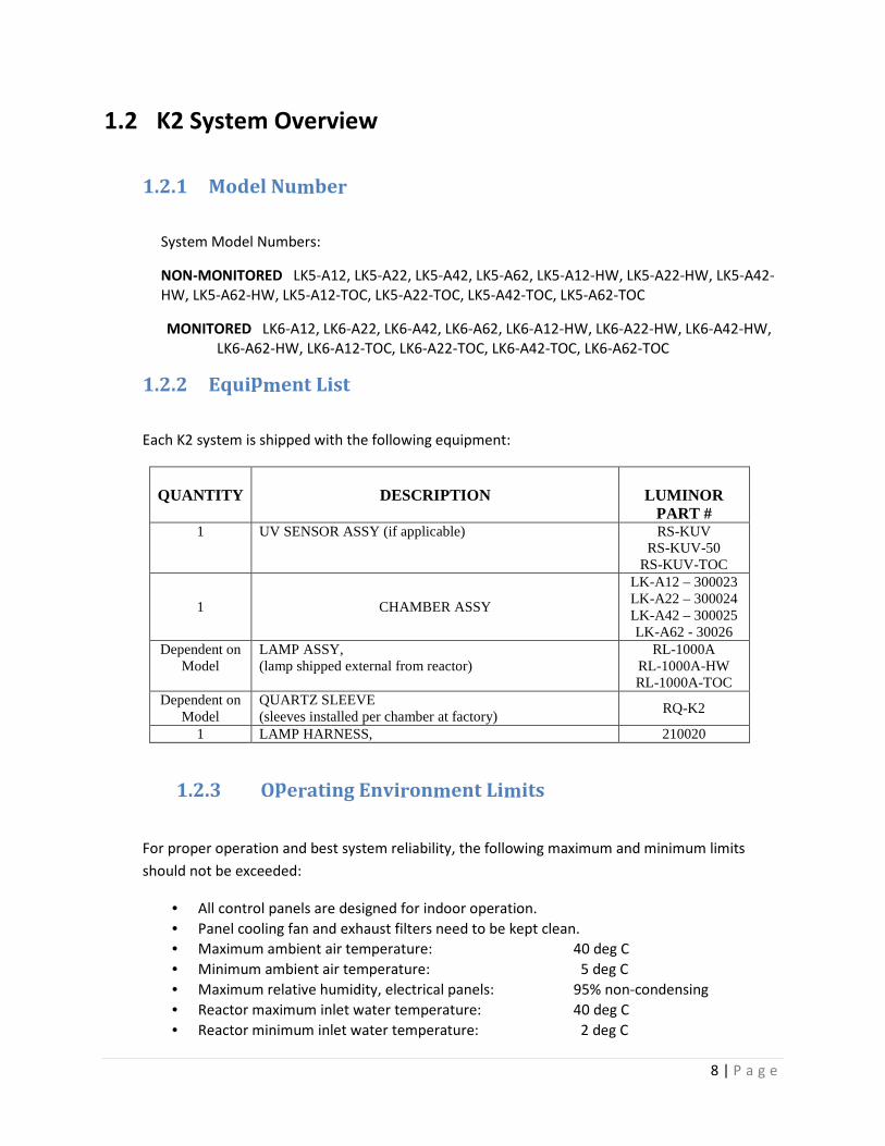
1.2.2 Equipment List
Each K2 system is shipped with the following equipment:
QUANTITY
DESCRIPTION
LUMINOR
PART # 1 UV SENSOR ASSY (if applicable) RS-KUV
RS-KUV-50 RS-KUV-TOC
1 CHAMBER ASSY
LK-A12 – 300023 LK-A22 – 300024 LK-A42 – 300025 LK-A62 - 30026
Dependent on Model
LAMP ASSY, (lamp shipped external from reactor)
RL-1000A RL-1000A-HW RL-1000A-TOC
Dependent on Model
QUARTZ SLEEVE (sleeves installed per chamber at factory)
RQ-K2
1 LAMP HARNESS, 210020
1.2.3 Operating Environment Limits
For proper operation and best system reliability, the following maximum and minimum limits
should not be exceeded:
• All control panels are designed for indoor operation.
• Panel cooling fan and exhaust filters need to be kept clean.
• Maximum ambient air temperature: 40 deg C
• Minimum ambient air temperature: 5 deg C
• Maximum relative humidity, electrical panels: 95% non-condensing
• Reactor maximum inlet water temperature: 40 deg C
• Reactor minimum inlet water temperature: 2 deg C
9 | P a g e
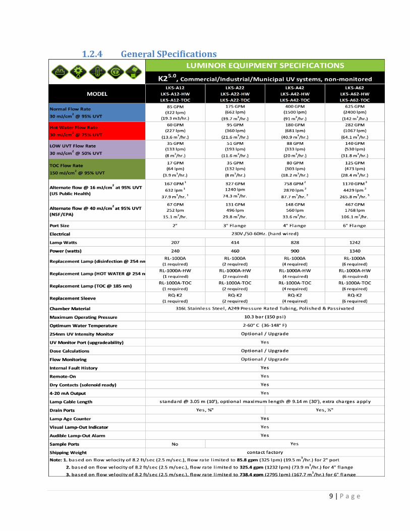
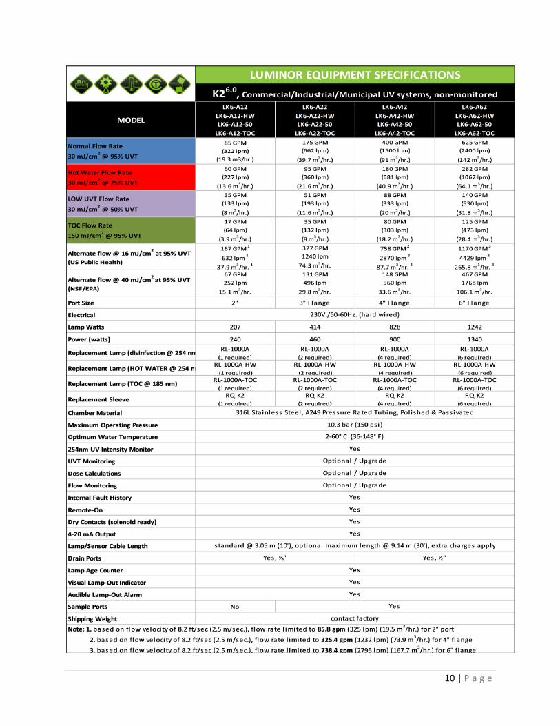
1.2.4 General Specifications
10 | P a g e
11 | P a g e
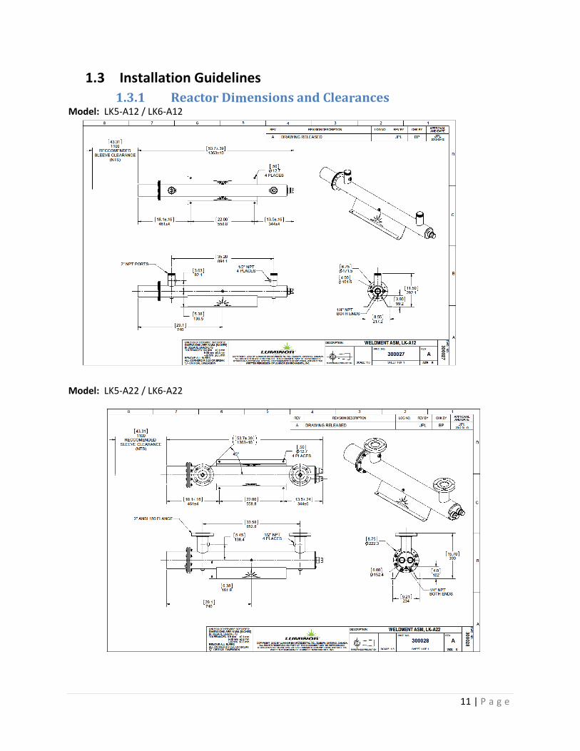
1.3 Installation Guidelines
1.3.1 Reactor Dimensions and Clearances Model: LK5-A12 / LK6-A12
Model: LK5-A22 / LK6-A22
12 | P a g e
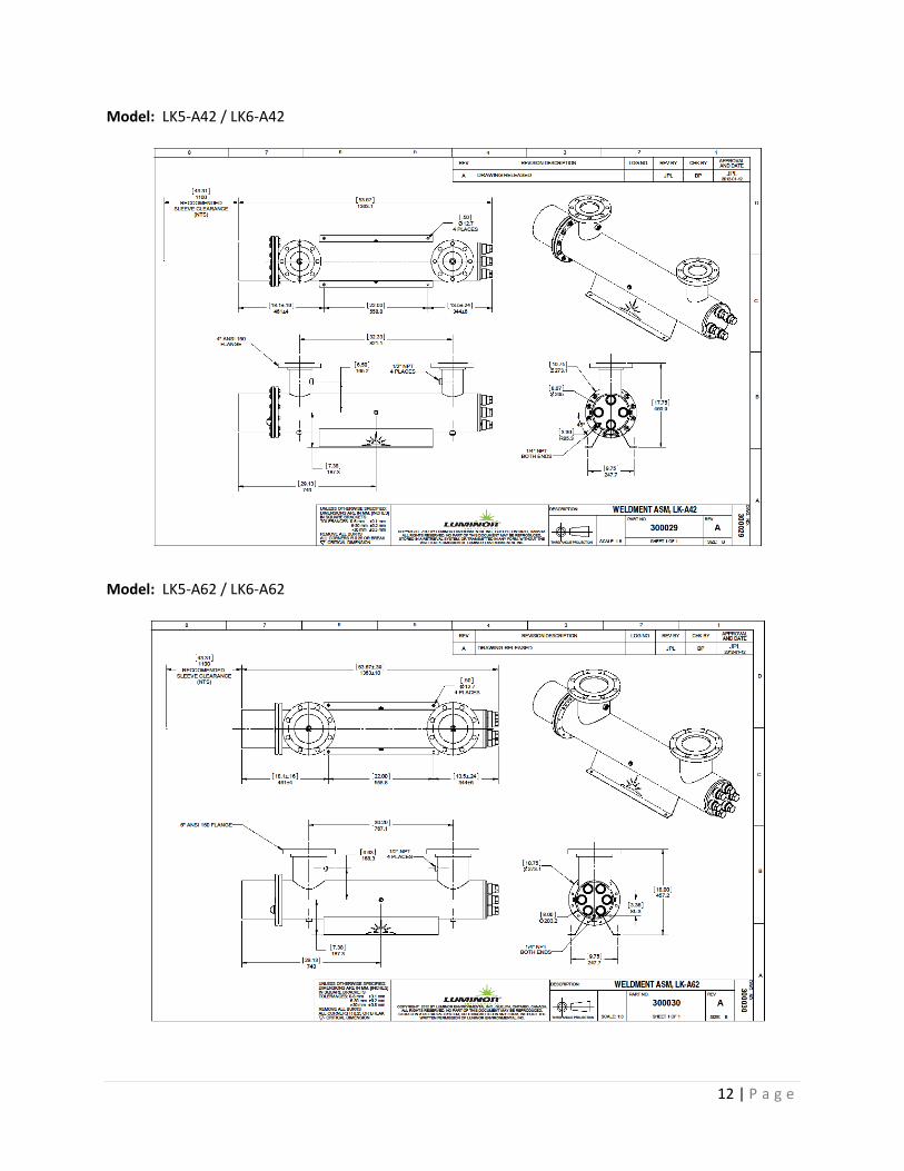
Model: LK5-A42 / LK6-A42
Model: LK5-A62 / LK6-A62
13 | P a g e
1.3.2 Reactor Installation, Piping, Leak-Test
Although the reactor of your K2 system was pressure tested with sleeves installed before leaving
the factory, shipping damage is a remote possibility; therefore it is recommended to do a visual
check before connecting piping, looking at each quartz sleeve installed in the reactor and
inspecting for signs of broken quartz glass. It is much easier to do this check and clean any broken
glass before the connection of pipes.
If the piping layout permits, it is recommended to raise the reactor approximately 600mm (2 ft)
above the floor level to make lamp changes and any other reactor maintenance tasks more “user-
friendly” and eliminating the need to get down onto the floor level.
Note the required clearance at connector end of the reactor, as shown on the reactor drawing.
Although the lamps can be changed entirely from the connector end of the reactor, it is also
required to have some access at the other end of the reactor to remove sleeve nuts.
The piping system should be designed with an air purge at its highest point, and the water flow
should be as free as possible of entrained air bubbles: UV reactors will not deliver their full design
UV dose if they are partially filled with air.
Generally, the reactors may be oriented with either end at the water inlet.
It is recommended to complete the reactor installation and connect related piping before
installing lamps and electrical panels. This allows the piping to be leak-tested without risk of
soaking electrical equipment, lamps, etc. Please see the next section for warnings on initial filling
of the reactor.
Before filling the reactor with water, the UV sensor should be installed. Also, any reactor drain
should be connected before filling.
1.3.3 WARNING: INITIAL WATER FLOW
Suddenly filling an empty reactor could potentially break the protective quartz sleeves.
Therefore, during commissioning or any time after the reactor is drained, it is strongly
recommended to gradually fill empty reactors.
Also, it is recommended to test the reactor with maximum water flow-rate conditions before
installing the UV lamps.
Damage as a result of sudden filling is not covered by warranty.
14 | P a g e
1.3.4 WARNING: WATER-HAMMER
Quartz sleeves can brake inside the reactor if water-hammer occurs. Water hammer is caused by
sudden closing of valves elsewhere in the piping system.
Therefore, it is strongly recommended to ensure that the piping and valve system is designed to
prevent water-hammer.
Damage as a result of water-hammer is not covered by warranty.
1.3.5 Electrical Panel Installation
The general equipment layout should have been predetermined before delivery of the UV
disinfection equipment, taking into account the location of electrical panels, orientation of
reactors, and the required clearances and lengths of interconnecting cable runs. If different
lengths of factory supplied cables are required, they will have to be ordered at additional charge.
The electrical panels are designed to be wall mounted by bolts of at least 5/16” diameter.
It is the responsibility of the purchaser to ensure that local electrical codes be satisfied during
installation.
15 | P a g e
1.3.6 Reactor Cable Bundle and Ground Connection
The reactor cable bundle is pre-wired at the factory to the control panel and includes the reactor
lamp cables with ceramic plugs and reactor ground conductor with ring terminal. At the “reactor
end” of this cable bundle is a “cable loom” that guides and protects the individual cable as they
enter the reactor end-housing.
Once the cable-loom is secured, it is imperative that the green/yellow ground conductor be fixed
via the ring terminal to the end-plate using the #10-32 screw provided.
1.3.7 UV Sensor Cable Connection
The sensor cable is connected to the six pin connector on the bottom of the control panel. Insert
the connector and twist the locking ring clockwise to secure the connection.
Please do not force this connector as damage to the pins may result.
16 | P a g e
1.4 Warranty
LIMITED WARRANTY STATEMENT
Products manufactured by LUMINOR Environmental Inc., (LUMINOR) are warranted to the original user
only to be free of defects in material and workmanship for a period as specified below. This warranty
only applies to the original purchaser and is not transferable.
UV SYSTEMS
Ten (10) year Limited Warranty on the stainless steel reactors, from the date of original
purchase, or installation (proper documentation required for verification).
ELECTRONICS
Three (3) year Limited Warranty on the ballasts and controllers, from the date of original
purchase, or installation (proper documentation required for verification).
UV LAMPS, UV SENSORS & QUARTZ SLEEVES
One (1) year Limited Warranty on all LUMINOR ultraviolet lamps, UV sensors and quartz
sleeves from the date of original purchase, or installation (proper documentation required for
verification).
LUMINOR warrants that it will repair, replace or refund, at LUMINOR’s sole option, any ultraviolet
system or component that is defective in materials or workmanship for the period as outlined above,
subject to the “Limitations of Warranty” as outlined below. LUMINOR's liability under this warranty shall
be limited to repairing or replacing at LUMINOR's option, without charge, F.O.B. LUMINOR’s factory or
authorized service depot, any product of that LUMINOR manufactures. LUMINOR will not be liable for
any costs of removal, installation, transportation, or any other charges which may arise in connection
with a warranty claim. Products which are sold but not manufactured by LUMINOR are subject to the
warranty provided by the manufacturer of said products and not by LUMINOR’s warranty. LUMINOR will
not be liable for damage or wear to products caused by abnormal operating conditions, accident, abuse,
misuse, unauthorized alteration or repair, or if the product was not installed in accordance with
LUMINOR’s printed installation and operating instructions.
LIMITATIONS OF WARRANTY
This warranty does not apply to any of the following:
• Water Quality Parameters lie outside of the following ranges
• Hardness > 120 mg/L (7 gpg)
• Iron > 0.3 mg/L (ppm)
• Manganese > 0.05 mg/L (ppm)
17 | P a g e
• Tannins > 0.1 mg/L (ppm)
• Turbidity > 0.1 NTU
• Transmittance (UVT) < 75%
• A product that has been incorrectly installed according to the technical installation manual.
• A product that has been modified in any manner, unless approved by the manufacturer.
• A product where the serial number has been altered defaced or removed.
• Damage caused by the use of parts that are not compatible, suitable and/or authorized by
LUMINOR for use with the product (e.g. non-original lamps or sleeves).
• Damage caused during shipment of the product.
• Water damage is found inside ballast housing or controllers
• Product is installed outdoors in direct contact with the environment (rain)
• Product is installed in freezing temperatures.
• Product is used in conditions that exceed LUMINOR’s specifications.
TO GET WARRANTY SERVICE
To obtain service under this warranty, you must first contact LUMINOR Customer Service at 855-837-
3801 (519-837-3800 outside of the US or Canada) to obtain a Warranty Return Authorization. You will
then need to return the product through the LUMINOR Dealer or Distributor where the product was
originally purchased, together with proof of purchase and installation date, failure date, and supporting
installation data. Unless otherwise provided, the Dealer or Distributor will contact LUMINOR for
instructions on returning the product. Any defective product to be returned to LUMINOR must be sent
freight prepaid; documentation supporting the warranty claim and/or a Return Material Authorization
must be included if so instructed.
LUMINOR WILL NOT BE LIABLE FOR ANY INCIDENTAL OR CONSEQUENTIAL DAMAGES, LOSSES, OR
EXPENSES ARISING FROM INSTALLATION, USE, OR ANY OTHER CAUSES. THERE ARE NO EXPRESS OR
IMPLIED WARRANTIES, INCLUDING MERCHANTABILITY OR FITNESS FOR A PARTICULAR PURPOSE,
WHICH EXTEND BEYOND THOSE WARRANTIES DESCRIBED OR REFERRED TO ABOVE.
THIS LIMITED WARRANTY IS THE SOLE AND EXCLUSIVE WARRANTY MADE BY LUMINOR WITH RESPECT
TO THE PRODUCT, AND IS GIVEN IN LIEU OF ANY OTHER WARRANTY. TO THE EXTENT ALLOWED BY
APPLICABLE LAW, ANY AND ALL EXPRESS OR IMPLIED WARRANTIES NOT SET FORTH HEREIN ARE
WAIVED AND DISCLAIMED, INCLUDING ANY IMPLIED WARRANTY OF MERCHANTABILITY OR FITNESS
FOR A PARTICULAR USE. LUMINOR LIABILITY UNDER THIS LIMITED WARRANTY IS LIMITED SOLELY TO
THOSE LIABILITIES SET FORTH ABOVE. IN THE EVENT THAT ANY PROVISION OF THIS LIMITED WARRANTY
SHOULD BE OR BECOME INVALID OR UNENFORCEABLE UNDER APPLICABLE LAW, THE REMAINING
TERMS AND CONDITIONS HEREOF SHALL REMAIN IN FULL FORCE AND EFFECT AND SUCH INVALID OR
UNENFORCEABLE PROVISION SHALL BE CONSTRUED IN SUCH A MANNER AS TO BE VALID AND
ENFORCEABLE.
18 | P a g e
1.5 Company Contact Information
Contractor INFORMATION:
Manufacturer INFORMATION:
LUMINOR Environmental Inc
290 Southgate Dr. Unit 2
Guelph, Ontario
N1G 4P5
Phone (519) 837-3800
Fax (519) 837-3808
19 | P a g e
Section 2 Operation, Control, Monitoring
2.1 Overview: System Operation, Control, Monitoring
The K2 UV systems utilize a Custom Control circuit board with an LCD display and LED indicators.
The Control board and ballast(s) are housed in a 304SS NEMA 12 enclosure to provide maximum
protection against external electrical noise, dust, insects, and water ingress.
The UV lamps, similar to general fluorescent lighting, are mercury vapour lamps that require
ballasts to regulate the current. The K2 product family use high frequency electronic ballasts to
provide stable lamp operation. These ballasts are power factor corrected and present low THD,
resulting in minimal disturbance to the electrical utility. There is a cooling fan to regulate the
panel temperature, and an intake filter to keep the panel clean. This filter should be cleaned in
the spring or each season in hot or dirty environments. The fan turns on when the lamps are on,
or the panel temperature is greater than 28°C.
This control system has relay inputs and outputs to facilitate integration into your control system.
A 24VDC relay coil serves as an input to turn the lamps on and off. Three output contact sets
(NO/NC) give the user a way to monitor if the K2 system is ready for flow, or if there are any
alarms.
The following pages detail the operation of the system and how to use the user interface.
20 | P a g e
2.2 LCD Display Menu System
The menu system is accessed by pressing the up and down button at the same time. The panel will
then prompt you to enter your password (00000 by default) by pressing the up and down buttons,
and the left button to switch digits. When you have entered your password press the enter key.
Press Up and Down to scroll through different menus and options. Press ENT to enter the menu or
adjust the option.
2.2.1 Shut down menu: With this menu you can choose if the reactor shuts down under certain
fault conditions. A setting of “YES” will cause the system to shut down.
2.2.2 If the setting has the LAMP FAILURE choice as “YES” the system will turn all the lamps off if
a single lamp fails. This alarm will remain set until acknowledged by user (Ref Section 2.4).
2.2.3 Setting the REACTOR TEMP choice to “YES” the system will shut down when the reactor
temperature is above the REACTOR TEMP setting in the ALARM THESH MENU. NOTE: If a
button is pressed you will exit this mode and the lamps will now be considered off. This
has been implemented as a safety precaution; if a person comes and inspects the system
the lamps cannot turn on while they are working on it. Press the | button to turn the
lamps back on. Otherwise, after the reactor temperature is five degress lower than the
setting in ALARM THESH MENU the system will restart the lamps if AUTO FAULT RESET is
set to YES.
2.2.4 Alarm Threshold Menu: This menu sets when the panel will trigger an alarm giving you
the freedom to customize your system to suit your needs. All the variables are always
visible. If a system has been ordered with this option it will be wired to the IO terminal
blocks and visible on the screen. Please consult the factory if you would like to have
these options included in your next order.
2.2.4.1 PANEL TEMP – Maximum allowed temperature before alarm. -2°C reset
2.2.4.2 REACTOR TEMP – Maximum allowed temperature before alarm -5°C reset
2.2.4.3 UV MINOR ALARM
2.2.4.4 UV MAJOR ALARM
2.2.4.5 UVT ALARM
2.2.4.6 DOSE
2.2.5 Analog Menu: This menu sets the maximum scaling for the analog channels
2.2.5.1 UV SCALE
2.2.5.2 UVT SCALE
2.2.5.3 FLOW SCALE
2.2.6 Alarm History: A list of alarms with the reactor running hour the fault was incurred.
2.2.7 Remote Control: A setting of “YES” sets the input of the 24VDC REMOTE ON relay as the
ON command to the system.
2.2.8 Lamp Warm-up Time: (Default = 180) Time in seconds the reactor will allow the lamps to
stabilize before the system allows flow.
2.2.9 Contrast: Sets the display contrast. 0=darkest 9= lightest
2.2.10 UV Units: Output for UV Intensity (if installed)
21 | P a g e
2.2.11 Flow Units: Output for Flow (if installed)
2.2.12 Temp Units: Celsius or Fahrenheit
2.2.13 Auto Fault Reset: Setting this option to “YES” will cause temperature (Panel &
Temperature) alarms to automatically reset if they are no longer above the ALARM THESH
MENU. Panel Temperature -2°C, Reactor -5°C for automatic reset.
2.2.14 Access Password: Change this to change the access password. There is no reset so record
it in a safe place.
2.2.15 Settings will be applied when you exit the menu system.
2.2.16 To acknowledge faults in the user menu press enter while looking at the fault.
2.3 Mode Selection
2.3.1 Local Mode: Using this panel as a stand-alone control panel you will turn the lamps on and off
with the | and O on the control panel. This is the default setting for the device.
2.3.2 Remote Mode: When using this panel as a module on a larger system you will want to set the
panel to work in remote mode. Enter the Menu System (UP and DOWN), enter your password
using LEFT and RIGHT to set the next digit then press enter. Press DOWN four times, press ENT,
press DOWN, press ENT, then press ESC and the panel will now be in ‘Remote Mode’. To turn
the lamps on and off +24 VDC to TERMINAL BLOCK #11, and 24 COMMON to TERMINAL BLOCK
#10.
2.4 Alarms
This panel monitors the UV system for abnormal conditions and outputs to the LCD screen. The
following are the parameters the control panel monitors:
Name Value Category Notes Low UV Alarm 12mW/cm2 Minor Set by User.
Clean the Sleeves, Replace the Lamps.
Low UV Alarm 8mW/cm2 Major Set by User. Clean the Sleeves, Replace the Lamps.
Lamp X Failure Lamp Failed Major If Multiple Lamps have failed, only the lowest number will be displayed. Replace the Lamp for a single lamp failure, replace the ballast for a double lamp failure.
High Panel Temperature 40°C Minor Clean the Intake Filter. High Reactor Temperature 50 °C Major Flow Water. Can be
triggered to shut the reactor down until the alarm has been acknowledged.
Lamp Life Alarm It is set in hours Minor Replace your lamps.
22 | P a g e
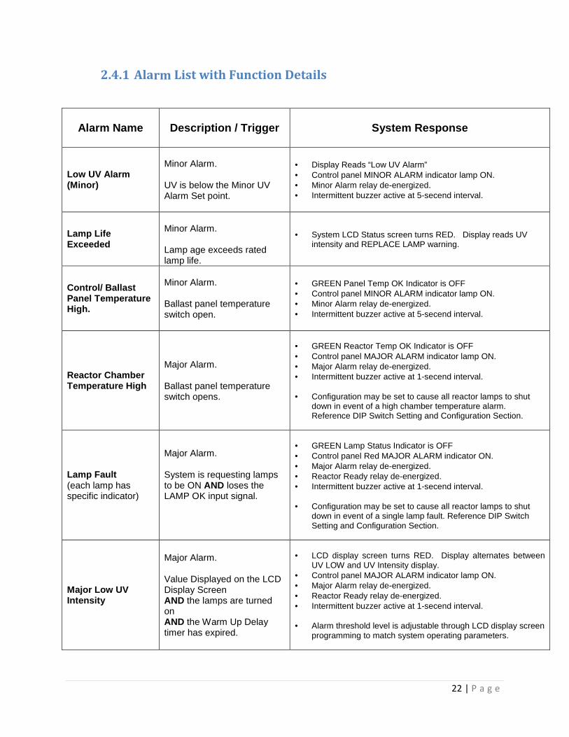
2.4.1 Alarm List with Function Details
Alarm Name
Description / Trigger System Response
Low UV Alarm (Minor)
Minor Alarm. UV is below the Minor UV Alarm Set point.
• Display Reads “Low UV Alarm” • Control panel MINOR ALARM indicator lamp ON. • Minor Alarm relay de-energized. • Intermittent buzzer active at 5-secend interval.
Lamp Life Exceeded
Minor Alarm. Lamp age exceeds rated lamp life.
• System LCD Status screen turns RED. Display reads UV intensity and REPLACE LAMP warning.
Control/ Ballast Panel Temperature High.
Minor Alarm. Ballast panel temperature switch open.
• GREEN Panel Temp OK Indicator is OFF • Control panel MINOR ALARM indicator lamp ON. • Minor Alarm relay de-energized. • Intermittent buzzer active at 5-secend interval.
Reactor Chamber Temperature High
Major Alarm. Ballast panel temperature switch opens.
• GREEN Reactor Temp OK Indicator is OFF • Control panel MAJOR ALARM indicator lamp ON. • Major Alarm relay de-energized. • Intermittent buzzer active at 1-secend interval. • Configuration may be set to cause all reactor lamps to shut
down in event of a high chamber temperature alarm. Reference DIP Switch Setting and Configuration Section.
Lamp Fault (each lamp has specific indicator)
Major Alarm. System is requesting lamps to be ON AND loses the LAMP OK input signal.
• GREEN Lamp Status Indicator is OFF • Control panel Red MAJOR ALARM indicator ON. • Major Alarm relay de-energized. • Reactor Ready relay de-energized. • Intermittent buzzer active at 1-secend interval. • Configuration may be set to cause all reactor lamps to shut
down in event of a single lamp fault. Reference DIP Switch Setting and Configuration Section.
Major Low UV Intensity
Major Alarm. Value Displayed on the LCD Display Screen AND the lamps are turned on AND the Warm Up Delay timer has expired.
• LCD display screen turns RED. Display alternates between
UV LOW and UV Intensity display. • Control panel MAJOR ALARM indicator lamp ON. • Major Alarm relay de-energized. • Reactor Ready relay de-energized. • Intermittent buzzer active at 1-secend interval. • Alarm threshold level is adjustable through LCD display screen
programming to match system operating parameters.

23 | P a g e
2.4.2 Control Board Output List
`
Description
Notes
Minor Alarm Minor Alarm relay: NO/NC dry contact.
Major Alarm Major Alarm relay: NO/NC dry contact.
Reactor Ready Dry Contact Set NO/NC to signal the reactor is ready for flow
2.4.3 Remote Control Interface Wiring
Signal Name
Terminal
Block Description
Remote On Signal (24V COMON) 10 Shorting out these two pins with a switch or contactor will activate remote starting of the reactor UV lamps when the LAMPS Off/On/Rem switch is in REM position.
Remote On Signal (+24VDC) 11
Flow Valve NC contact 12
Flow Valve Com 13
Flow Valve NO contact 14
Minor Alarm NO contact 15
Minor Alarm common 16
Minor Alarm NC contact 17
Major Alarm NO contact 18
Major Alarm common 19
Major Alarm NC contact 20
UV System Outputs
24 | P a g e
Section 3 Maintenance
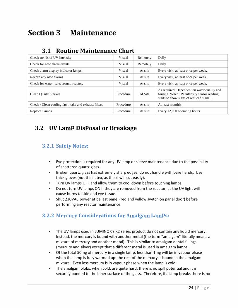
3.1 Routine Maintenance Chart Check trends of UV Intensity Visual Remotely Daily
Check for new alarm events Visual Remotely Daily
Check alarm display indicator lamps. Visual At site Every visit, at least once per week.
Record any new alarms Visual At site Every visit, at least once per week.
Check for water leaks around reactor. Visual At site Every visit, at least once per week.
Clean Quartz Sleeves Procedure At Site As required. Dependent on water quality and fouling. When UV intensity sensor reading starts to show signs of reduced signal.
Check / Clean cooling fan intake and exhaust filters Procedure At site At least monthly.
Replace Lamps Procedure At site Every 12,000 operating hours.
3.2 UV Lamp Disposal or Breakage
3.2.1 Safety Notes:
• Eye protection is required for any UV lamp or sleeve maintenance due to the possibility
of shattered quartz glass.
• Broken quartz glass has extremely sharp edges: do not handle with bare hands. Use
thick gloves (not thin latex, as these will cut easily).
• Turn UV lamps OFF and allow them to cool down before touching lamps.
• Do not turn UV lamps ON if they are removed from the reactor, as the UV light will
cause burns to skin and eye tissue.
• Shut 230VAC power at ballast panel (red and yellow switch on panel door) before
performing any reactor maintenance.
3.2.2 Mercury Considerations for Amalgam Lamps:
• The UV lamps used in LUMINOR’s K2 series product do not contain any liquid mercury.
Instead, the mercury is bound with another metal (the term “amalgam” literally means a
mixture of mercury and another metal). This is similar to amalgam dental fillings
(mercury and silver) except that a different metal is used in amalgam lamps.
• Of the total 50mg of mercury in a single lamp, less than 1mg will be in vapour phase
when the lamp is fully warmed up: the rest of the mercury is bound in the amalgam
mixture. Even less mercury is in vapour phase when the lamp is cold.
• The amalgam blobs, when cold, are quite hard: there is no spill potential and it is
securely bonded to the inner surface of the glass. Therefore, if a lamp breaks there is no
25 | P a g e
liquid mercury to clean up: the pieces of the lamp, including the amalgam blobs, should
be swept into a plastic or cardboard container.
3.2.3 Lamp Breaks Inside Reactor
• In this event there will be a lamp failure alarm, and possibly low UV dose: the control
system may be configured to shut down the reactor and close the inlet and outlet
valves.
• There will be no water leakage or contamination of process water as the sleeve is still
intact.
• First remove the large pieces of broken lamp. Then carefully clean the inside of the
sleeve by pushing a soft cloth through the sleeve with a clean wood dowel or clean
plastic pipe of approximately ¾” diameter. Note that this will require removal of the
“blind” sleeve nut at the other end of the reactor so that the cloth can be pushed all the
way through. Capture the debris and cloth in a plastic bag dispose of according to local
regulations (treat the same as fluorescent lamp).
3.2.4 Lamp and Sleeve Break Inside Reactor
• In this event there will be a lamp failure alarm and possibly low UV dose alarm: the
control system may be configured to shut down the reactor and close the inlet and
outlet valves.
• Water leakage will be obvious at the lamp-plug end.
• The reactor will have to be drained and cleaned. First recover the broken lamp and
sleeve debris and put them into a plastic or cardboard container for disposal.
• The reactor should be further cleaned with soft cloths before reassembly.
• If there is a trap down-stream of the reactor, it should be drained and cleaned of debris
that might have been carried through.
• Capture all debris and cloth in a plastic bag and dispose of according to local regulations
(treat the same as fluorescent lamp).
26 | P a g e
3.3 Lamp Installation / Removal
• The K2 reactor is shipped with the quartz sleeves installed inside the reactor, ready to accept
the lamps which are shipped in separate protective packaging.
• SAFETY NOTES:
� Eye protection is required for any UV lamp or sleeve maintenance due to the
possibility of shattered quartz glass during an accidental breakage.
� Turn UV lamps OFF and allow them to cool down before touching lamps.
� Do not turn UV lamps ON if they are removed from the reactor, as the UV light
will cause burns to skin and eye tissue.
� Shut panel power OFF before any reactor maintenance.
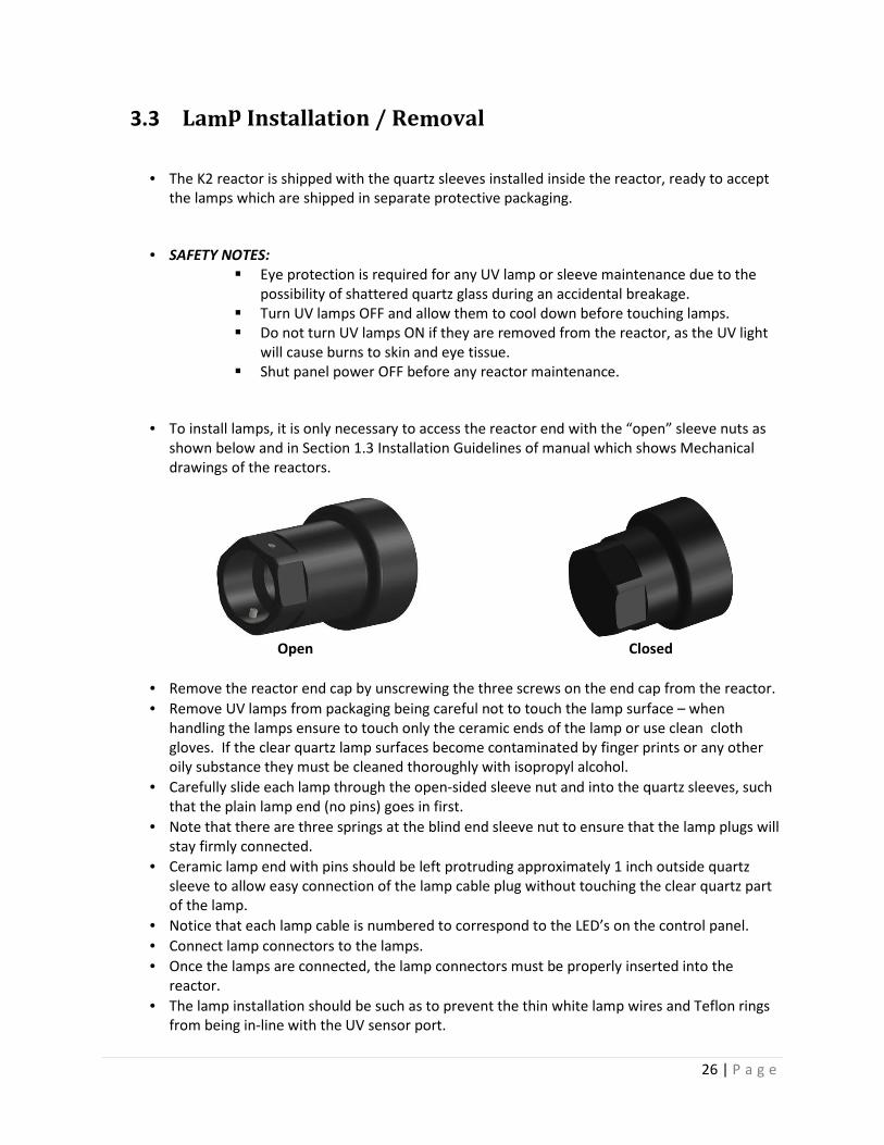
• To install lamps, it is only necessary to access the reactor end with the “open” sleeve nuts as
shown below and in Section 1.3 Installation Guidelines of manual which shows Mechanical
drawings of the reactors.
Open Closed
• Remove the reactor end cap by unscrewing the three screws on the end cap from the reactor.
• Remove UV lamps from packaging being careful not to touch the lamp surface – when
handling the lamps ensure to touch only the ceramic ends of the lamp or use clean cloth
gloves. If the clear quartz lamp surfaces become contaminated by finger prints or any other
oily substance they must be cleaned thoroughly with isopropyl alcohol.
• Carefully slide each lamp through the open-sided sleeve nut and into the quartz sleeves, such
that the plain lamp end (no pins) goes in first.
• Note that there are three springs at the blind end sleeve nut to ensure that the lamp plugs will
stay firmly connected.
• Ceramic lamp end with pins should be left protruding approximately 1 inch outside quartz
sleeve to allow easy connection of the lamp cable plug without touching the clear quartz part
of the lamp.
• Notice that each lamp cable is numbered to correspond to the LED’s on the control panel.
• Connect lamp connectors to the lamps.
• Once the lamps are connected, the lamp connectors must be properly inserted into the
reactor.
• The lamp installation should be such as to prevent the thin white lamp wires and Teflon rings
from being in-line with the UV sensor port.
27 | P a g e
• Notice on the inside of the sleeve gland nut 2 protruding metal pins: the lamp connector is a
“bayonet” style with matching notches that must engage with the two metal pins inside the
sleeve nut.
• Once the pins and notches have been lined up the connector will easily push into the sleeve
gland nut: There is a reasonably strong spring at the far end of the sleeve pushing back on the
connector: this spring force is required to ensure that the lamp and connector remain fully
mated over time.
• Once fully inserted, turn the bayonet connector to the right to lock it into position and
maintain spring force on the lamp.
• Reset the lamp life hours and counter after installing a new lamp using the control system
operator interface.
• Lamp removal is essentially a reverse of the above procedure, with a main “tip” being to have
a clean safe place to place them outside of the reactor.
3.4 Lamp Change Interval
Germicidal lamps will lose some percentage of their output as they accumulate operating hours.
With the ‘state-of-the-art’ lamps utilized in the LUMINOR K2- series, this aging effect is relatively
minimal, especially compared to older lower cost technology lamps. However, it is important to
recognize that all lamps have a finite life, and therefore the UV lamps must be replaced at a
maximum of 12,000 operating hours.
3.5 Sleeve Removal
• To remove quartz sleeves from the system the reactor must be drained of all water.
• Reference mechanical drawings in Section 1.3
• Remove the end cap from the end of the reactor by unscrewing the three screws.
• Both sets of gland nuts must be removed.
• There is an o-ring on both ends of each quartz sleeve that must be removed.
• The quartz sleeves can now be pulled from the reactor from the lamp removal end of the
reactor.
CAUTION: Please pull the sleeves very gently from the reactor ensuring that the sleeves stay
as level as possible so as to not break the sleeve.
3.6 Manual Sleeve Cleaning
• Once the sleeves have been removed from the reactor they may be cleaned manually. Quartz
sleeve may look clear but it is quite common to have deposits on the sleeve that are not
visible to the eye but can substantially block UV light.
• Cleaning can be done using a soft cloth and an acid based scale remover such as Lime-Away or
CLR. Scale and iron based coatings, even if not visible to the naked eye, can only be removed
with an acid: alcohol will have little or no effect.
28 | P a g e
• Soak the cloth with Lime-Away or CLR and gently begin rubbing the length of the quartz sleeve
ensuring that no chemical gets inside of the quartz sleeve.
• Rub the sleeve’s entire diameter and length until the entire surface has been wiped down.
• Using a dry, soft cloth wipe away any access cleaning solution before replacing the sleeve.
3.7 Sleeve Installation
• Follow the Sleeve Removal steps first.
• With gloved hands remove cleaned or new sleeves from packaging, ensuring that the sleeves
are free from fingerprints, dirt, dust etc. Fingerprints or other oily contamination should be
cleaned with a soft cloth and isopropyl alcohol.
• Slide sleeves into each position on face plate, ensuring that you do not allow the sleeve to fall
to the bottom of the reactor.
• Guide each sleeve carefully into its position at the opposite end of the reactor and gently push
it through until it reaches the endplate and pokes outside of the reactor approximately ¼” –
½”.
• Once each sleeve has been replaced slide an o-ring onto each end the sleeve until it butts up
against the face plate of the reactor to ensure a sufficient seal.
• NOTE: When replacing the quartz sleeves new o-rings must be installed.
• Ensure that nuts are properly installed on both ends of the reactor
• When installing the gland nuts, on end of the reactor opposite the lamp connectors, a wrench
must be used: these sleeve gland nuts will bottom-out against the stainless steel stubs,
ensuring maximum o-ring compression before over-tightening occurs.
• The gland nuts on the lamp removal end of the reactor can be hand-tightened: again, these
sleeve gland nuts will bottom-out against the stainless steel stubs, ensuring maximum o-ring
compression before over-tightening occurs.
3.8 UV Sensor
3.8.1 UV Sensor Installation
• The sensor itself will not be shipped installed in the reactor: it is packaged separately to
prevent damage during shipping and reactor installation.
• Reference mechanical drawings in section 1.3
• It is recommended to install sensor before filling the reactor.
• Remove the sensor body from its packaging.
• Remove the plug assembly in the side the sensor is to be installed (if present).
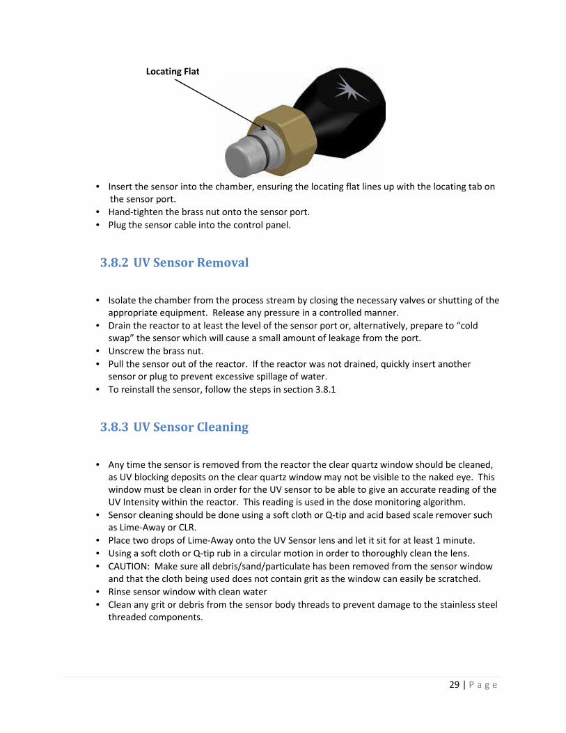
• Raise the brass nut and identify the locating flat as shown below:
29 | P a g e
• Insert the sensor into the chamber, ensuring the locating flat lines up with the locating tab on
the sensor port.
• Hand-tighten the brass nut onto the sensor port.
• Plug the sensor cable into the control panel.
3.8.2 UV Sensor Removal
• Isolate the chamber from the process stream by closing the necessary valves or shutting of the
appropriate equipment. Release any pressure in a controlled manner.
• Drain the reactor to at least the level of the sensor port or, alternatively, prepare to “cold
swap” the sensor which will cause a small amount of leakage from the port.
• Unscrew the brass nut.
• Pull the sensor out of the reactor. If the reactor was not drained, quickly insert another
sensor or plug to prevent excessive spillage of water.
• To reinstall the sensor, follow the steps in section 3.8.1
3.8.3 UV Sensor Cleaning
• Any time the sensor is removed from the reactor the clear quartz window should be cleaned,
as UV blocking deposits on the clear quartz window may not be visible to the naked eye. This
window must be clean in order for the UV sensor to be able to give an accurate reading of the
UV Intensity within the reactor. This reading is used in the dose monitoring algorithm.
• Sensor cleaning should be done using a soft cloth or Q-tip and acid based scale remover such
as Lime-Away or CLR.
• Place two drops of Lime-Away onto the UV Sensor lens and let it sit for at least 1 minute.
• Using a soft cloth or Q-tip rub in a circular motion in order to thoroughly clean the lens.
• CAUTION: Make sure all debris/sand/particulate has been removed from the sensor window
and that the cloth being used does not contain grit as the window can easily be scratched.
• Rinse sensor window with clean water
• Clean any grit or debris from the sensor body threads to prevent damage to the stainless steel
threaded components.
Locating Flat
30 | P a g e
3.9 Cooling Fans and Exhaust Filters
The Control Panel enclosure utilizes filter fans and exhaust vents. These filters provide protection
against dirt, dust, and water splash.
However, these filters do become plugged, especially if the environment tends to be dusty, which
can lead to shortened life of the ballasts and other electrical components as well as high panel
temperature alarms.
Usually it is sufficient to simply clean the filters, which is an easy task as the black grill covers
simply snap off from the exterior of the panel: a small flat screwdriver will help to pry the cover
off, and a notch for the screwdriver is provided.
If the filters become damaged or can’t be cleaned, they can be replaced inexpensively.
Any fans that are not rotating freely or otherwise fail must be replaced.
The cooling fans and exhaust filters should be checked at least once per month.
3.10 Common Replacement Parts
UV Lamps PN : RL-1000A (K2 system), RL-1000A-HW (K2 Hot Water system), RL-
1000A-TOC (K2 TOC system)
Quartz sleeves PN: RQ-1000
Lamp Ballast PN: RB-K21 LK5-A12, LK6-A12),RB-K22 (LK5-A42, LK5-A62, LK6-A42,LK6-A62)
UV Sensor Assembly PN: RS-KUV (K2 & K2 TOC systems), RS-KUV-50 (K2 low UVT system), RS-
KUV-TOC (K2 TOC system)
4 Field Notes