Embed Size (px)
Citation preview
Report No. CDOT -DTD-R-93- 12
CURTAIN DRAINS
Thomas R. Hunt Colorado Department of Transportation
4201 East Arkansas Avenue
Denver. Colorado 80222
Final Report
December. 1993
Prepared in cooperation with the
U.S. Department of T ransporta ti on Federal Highway Administration
ACKNOWLEDGEMENTS
I would like to thank the panel members: Keith Durfee, Garth Englund, Marcia Folsom, Werner Hutter, steve Smith, and Ted Vickers for their input on this project.
ii
Technical Report Documentation Page
1. R.pert H •• 3. Roci,; ... " C.t.lo, Ne.
c:oor-DID-R-93-12
•• T i tl. _" Sultti tl. S. R • .,o" c., • 0Jrtain Drains - .. ,.
~ 1~93 6. P .,f ...... i lll O't"'; loti." C •••
105.03 ~--:""""":,",""",,:,,,"-:--_______________________ ~8. P.,f."";,,, O"o"i.orio" Rep." H ••
7. A .......... )
'Ihamas R. Hunt 9. Perf."";,,, O,. .. iaeti ... H_ • ... Ad .....
Colorado Department of Transportation Division of Transportation Development 4201 Fast Arkansas Avenue
CIXn'-DID-R-93-12 10. W." U,,;, .... (TRAIS)
11 • . Co" ... c' ., G •• ", ....
HPR-B Derwer, a::> 80222 13. T y., •• f Itep." .". P .,io. C .... ,.ci
~~~---------------~~~-------------------------------------~ 12. Sp_ .... i". ""._e., 1'4_ ... Add ....
Colorado DepartlIent of Transportation 4201 Fast Arkansas Avenue Derwer, a::> 80222 1:1. Su .. .,I ..... " • ." 1'4 ....
Final Report 1 •• Spe" •• ,i"1 A •• "ey e ... 741.102
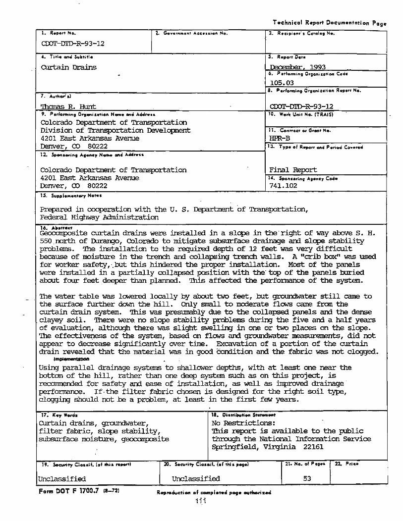
Prepared in cooperation with the U. s. Department of Transportation, Federal Highway Administration 16. AIt.tr.ct Gecxxlmp:>site curtain drains were installed in a slope in the· right of way abov'e S. H. 550 .north of D.lrango, Colorado to mitigate subsurface drainage am slope stability problems. '!he installation to the required depth of 12 feet was very difficult because of misture in the trench am collapsin;J trench walls. A "crib box" was used for worker safety, '. but this .hindered the proper installation. Most of the panels were installed in a partially collapsed position with the" top of the ' panels buried about four feet deeper than planned. '!his affected the perfonnance of the system.
The water table was lowered locally by about two feet, but groun::iwater still came .to the surface further down the hill. Only srrall to mcdel:ate fla-JS came fran the curtain drain system. 'll1is was presumably due to the collapsed panels am the dense clayey soil. '!here were. no slope stability problems durin;J the five am a half years of evaluation, although there was slight swellin;J in one or two places on the slope. The effectivel)ess of the system, based on flows ani groun::iwater neasurements, did not appear to decrease significantly over time. Excavation of a portion of the curtain drain revealed that the material was in good Condition am the fabric was not clogged. I",~ •
Using parallel drainage systems to shallower depths, with at least one near the bottom of the hill, rather than one deep system such as on this project, is recarnmended for safety am ease of installation, as well as jnproved drainage' perfonnance. If, the filter fabric chosen is designed for the right soil type, cloggirg should not ,be a problem, at least in the first few years.
17. IC • ., W.,d.
curtain drains, groundwater, filter fabric, slope stability, subsurface m::>isture, gec:X::an1p:)Site
18. Di.ltillu" ... St_ ... t
No Restrictions: .. 'nlis report is available to the public through the National Information service Sprin;Jfield, Virginia 22161
19. Security Ct ... if. (of Ifti. re..,.,' Z. Security CI ...... l.1 tftis ..... ) 21. No •• f P •••• 12. Pri ••
Unclassified unclassified 53
FOnll DOT F 1700.1 (8-72' R.,,.ducti_ .1 COMplot.d Pot. autMriZH
iii.
I
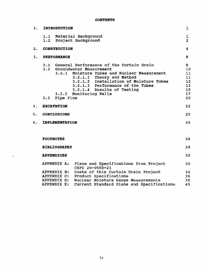
CONTENTS
1. INTRODUCTION
1.1 Material Background 1.2 Project Background
2. CONSTRUCTION
3 • PERPORHDCE
1
1 2
4
8
3.1 General Performance of the curtain Drain 8 -3.2 Groundwater Measurement 10
3.2.1 Moisture Tubes and Nuclear Measurement 11 3.2.1.1 Theory and Method 11 3.2.1.2 Installation of Moisture Tubes 12 3.2.1.3 Performance of the Tubes 13 3.2.1.4 Results of Testing 15
3.2.2 Monitoring Wells 17 3.3 Pipe Flow 20
4. EXCAVATION
5 . CONCLUSIONS
6. IMPLEMENTATION
POOTNOTES
BIBLIOGRAPHY
APPElmICBS
APPENDIX A:
APPENDIX B: APPENDIX C: APPENDIX D: APPENDIX E:
Plans and Specifications from Project CXFC 20-0550-21 Costs of this curtain Drain Project Product specifications Nuclear Moisture Gauge Measurements CUrrent Standard Plans and Specifications
iv
22
25
26
28
29
3-0
30
34 36 38 45
1. INTRODUCTION
1.1 Material Background
When a highway is built into the side of a slope, there is the potential for problems from surface runoff and groundwater from the hill above the roadway. The two primary problems with which highway designers, constructors and maintenance personnel are concerned are slope stability and moisture relat.ed damage to the pavement or pavement structure.
When there is a potential for one .of these two problems, mitigation measures must be taken. If the problem is slope stability, there are three basic methods of mitigation during design and/or construction. These are:
1. Lessen the severity of the slope by grading work or if necessary changing the alignment of the roadway.1
2. Install some sort of retaining wall. 3. Provide positive drainage of the surface and ground
water. This may involve the use of a "curtain Drain".
If the problem is moisture under the pavement, mitigation measures include:
1. Raise the surface elevation of the roadway. 2. Make the side ditches deeper. 2 3. Place interceptor drains, also called under-drains,
between the slope and the roadway. (If the pavement moisture problem is from rain or surface water on the roadway, this is a separate problem that can b.e solved by providing positive drainage by the use of a drainable base and edge-drains.)
option "3" for each problem above can involve the use of geocomposite materials or the use of a "French Drain" consisting of geofabric surrounding coarse backfill with or without a collector pipe at the bottom • . The main differences between a "curtain drain" and an "interceptor drain" or "underdrain" is that the former is usually placed further from the edge of the roadway in the hill above the roadway, and usually extends deeper into the ground. Geocomposites, as used in the project presented here, have been in use for this purpose since the early 1980's.
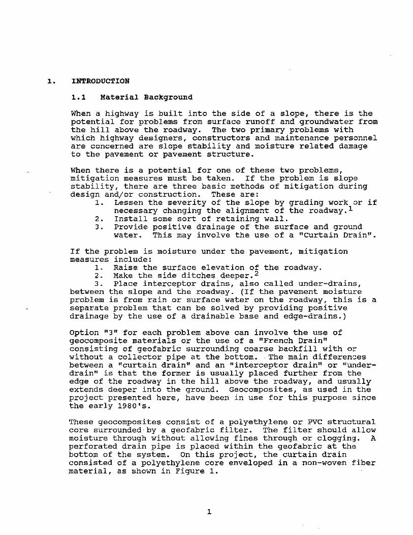
These geocomposites consist of a polyethylene or PVC structural core surrounded -by a geofabric filter. The filter should allow moisture through without allowing fines through or clogging. A perforated drain pipe is placed within the geofabric at the bottom of the system. On this project, the curtain drain consisted of a polyethylene core enveloped in a non-woven fiber material, as shown in Figure 1.
1
Figure]. This photo shotvs the "egg-crate lf core of the curtain drain surrounded by the non-woven filter material.
~ . 2 pro j e,ri: Back qro,un;:l
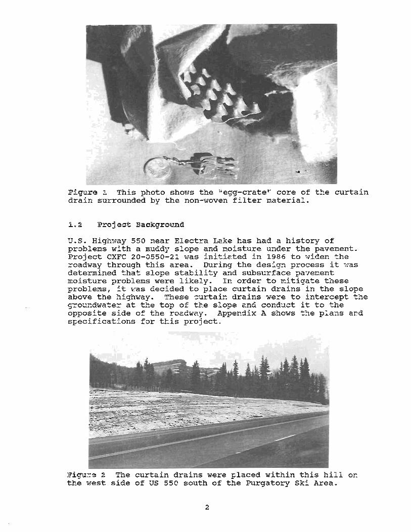
D. S. High::ray 550 near Electra Lake has had a history of pr,;:,blems with a muddy slope and moisture under the pavement. project CXFC 20-a550-21 was initiated in 1986 to widen the roadway through this area. During the design process it was determined that slope stability and subsurface pavenent moisture problems were likely. In order to mitigate tliese proble:ms, it vias decided to place curtain drains in the slope above the highway. These curtain drains were to intercept the groundwa~er at the top 0= the slope and conduct it to the opposite side of the roadway. Appendix A shows t..'1e plans and specifications for t~is project.
]!'ig'llre 2 The curtain drains were placed within this hil l on the west side of us 55e south of the Purgatory Ski Area .
2
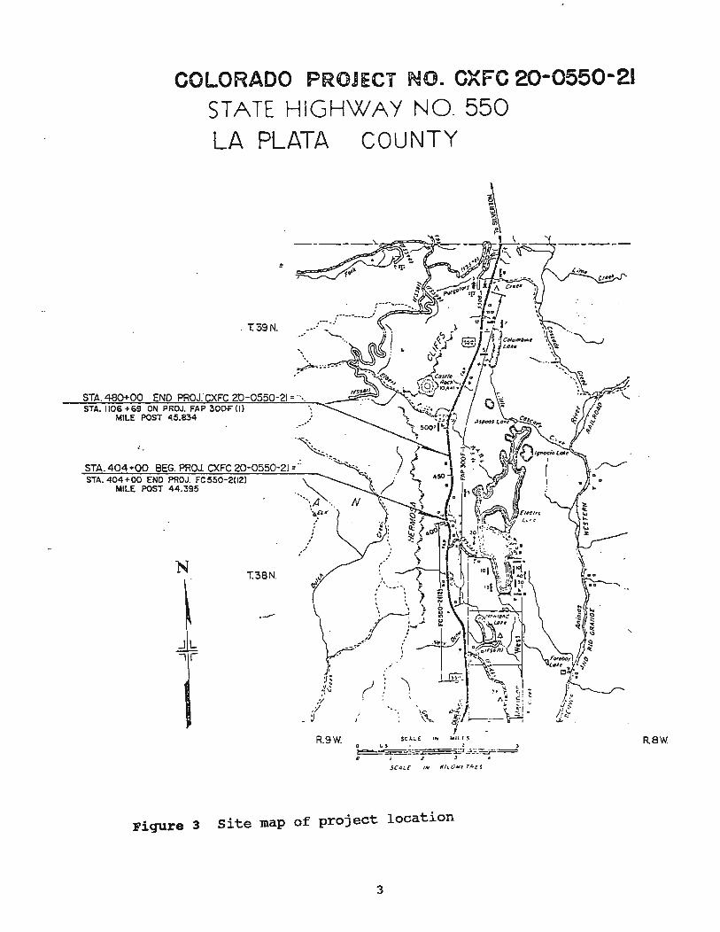
COLORADO PROJECT NO. CXFC 20-0550-21 STATE HIGHWAY NO. 550
LA PLATA COUNTY
. T39N.
STA. 404 +00 BEG. PROJ. CXFC 20-0550-21 =.0 STA. 404+00 ENO PROJ. FC550-2UZl
MILE POST 44.395
N
JL .,r
T.38No
.-'
O"'~o oo ').cu
:' . , . /','
, I
".
'\ ,
R.9W. SCI. .. ( IH o ~' I : , ~= _::== -:CZ'.i-.:.:=.::r_o= " ; ~ J •
SC.Gi,C Iii J(J,V4l1 r.-cs
Figure 3 site map of project location
3
0,",---,
...
RBW
2. CONSTRUCTION
On July 1 and 2, 1987 Werner Hut~er of C~OT was at the p~oject site north of Electra Lake on S.H. 550 to observe the installatior. !or the Research Branch. This partict:.lar site ~vas the third of four curtain drain sites in the state.
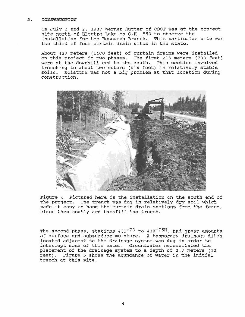
About 427 meters (1400 feet) 0= curtain drains were installec o~ this project in two phases. The first 213 meters (700 feet) were at the downhill end to the south. This section involved trenching to about two meters (six feet) in relatively stable soils. Moisture was not a big problem at that location during construction.
Figure 4 Pictured here is the installation on the south end of the proj ect. "The trench ~las dug in relatively dry soil which nade it easy to hang the curtain drain sections from the fence, place theD neatl y and cackfill the t~ench.
The second phase, stations 431+73 to 438+75H , had great amounts of surface and. subsurface moisture. A temporary drainage di-cch located adjacent to the drainage system was dug in order to inte~~ept some of this -:vater. Grcur.dwater necessitated the placement of the drainage system to a depth of 3 . 7 meters (12 feet,. Figure 5 shows the abundance of wate~ in "the i~itial trench at this site.
4
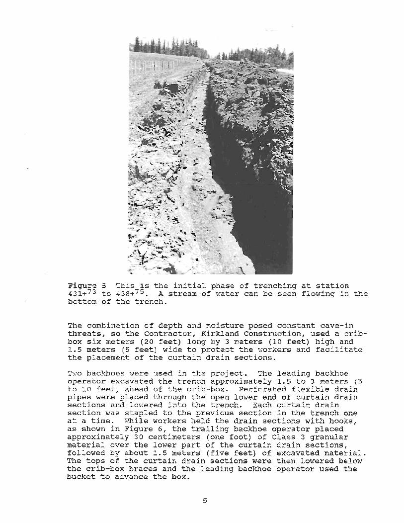
Figure 5 Ttis is the initial phase of trenching at station 431+73 to 438+75 • A stream of water can be seen flowing i~ the bctto~ of ~~e trench.
7he cOI!lbination of depth and moisture posed constant cave-in threats, so the Co~tractor, Kirkland Construction, ~sed a cribbox six met-ers (20 feet) long by 3 I!!.eters (10 feet) high and 1. 5 meters (5 feet ) wide to protect. t.he :-:orkers and fac:"litate the placement of the curtain drain sections.
1":.;0 backhoes were used i n t.he project. The leading backhoe operator excavated the trench approximatel y 1.5 to 3 neters (5 to 1 0 feet ) ahead ~f the crib-box. Perforated flexi~:e drain pipes were placed throagh t.he open lower end of curtain drain sections and 10vJered into the trench. Each curtai!1 drain section was stapl ed to the previous section in the trench one at. a time. vlhile workers ~e:d the drain sections with hooks , as shown in Figure 6, the trailing backhoe operator placed approximatel y 30 centi meters (one foot) of Class 3 granular materia_ over the lower part of the curtain drain sections, fol l owed by about 1.5 meters (five feet) of excavated material . The ~ops of the curtain drain sections were then lowered below the crib-box braces and the l eading backhoe operator used the bucket to advance t::e box.
5
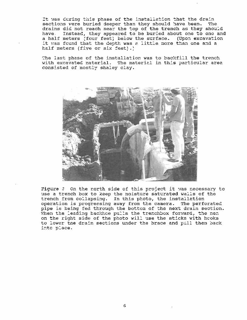
:t was during this phase of t~e i nstal lation that the dra~n sectio:ls V.rere buried deeper than they should have been. The drains did not reach nea= the top of the trench as they shoul d have . Instead, they appeared to be buri ed about one to one and a half meters 'four feet) below the surface. (Upon excava~ion it was found that the depth was a little nore than one and a half meters (five or six feet). )
The last phase of the installation was to backfil l t3e trench with excavated ~aterial. The material in this particul ar area consi.sted of mostl y shal ey clay.
~i~~re 6 On the north side of this project it was necessary to use a trench box to keep the moisture saturated walls of the trench from collapsing. In this photo, the installation operation is progressing away from the camera. The perforated pipe is being fed through the botto~ of the next drain section. !\"hen the l eading backhce pu_ls the trenchbox for.tlard, the men on ~he right side of the photo wil l use the sticks with hooks to :;"ower the drain sections under the brace and p~ll then back i~to p:'ace .
6
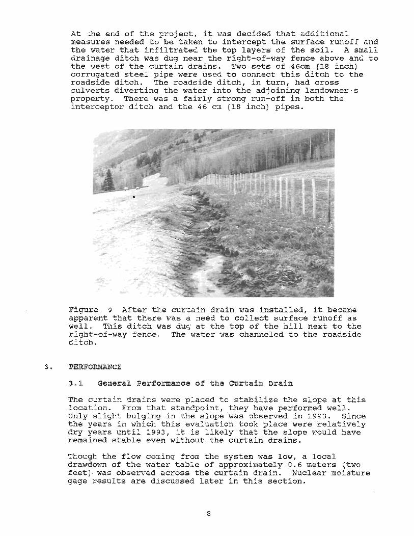
At the end of tha proj ect, it '\lIaS decided that additional measures needed to be taken to intercept the surface runoff and the water that infiltrated the top layers of the soil. A small drainage ditch was dug near the right-of-vlay fence above and to the west of the curtain drains. Two sets of 46cm (18 inch) corrugated steel pipe were used to connect this ditch tc the roadside ditch. The roadside ditch, in turn, had cross c ulverts diverting the water into the adjoining landowner ' s property. There was a fairly strong run-off in both the interceptor ditch and the 46 cm (18 inch) pipes.
Fi~~re 9 After the cur~ain drain was installed, it be~a~e apparent ~hat there was a ~eed to collect surface runoff as well. This ditc~ was dug- at the top of the hill next to the righ::-of-way =ence . The water ~vas channeled to the roadside (Etch.
3 • ~ERFOru~..NCE
3 .~ General Pe r forma_ce of t he Curtain Dr a in
The c t:rta:':: drair:.s we::-e placed tc s~abilize the sl:>pe at this locat~on. From that standpoi nt, they have pe=formed well. Only s .... igh t. bulging in the slope was observed in 1993. Since the years in which this evaluation took p l ace were relativel y dry years unti l 1993, it is ~ikely that the slope would have remained stable even without the curtain drains.
Though the flow co:dng from the system Ivas low I a local drawdown of the water table of approximatel y 0 .6 meters (two feet . was observed across the curtai n drai:1. Nuclear moisture gage results are discussed later in this section.
8
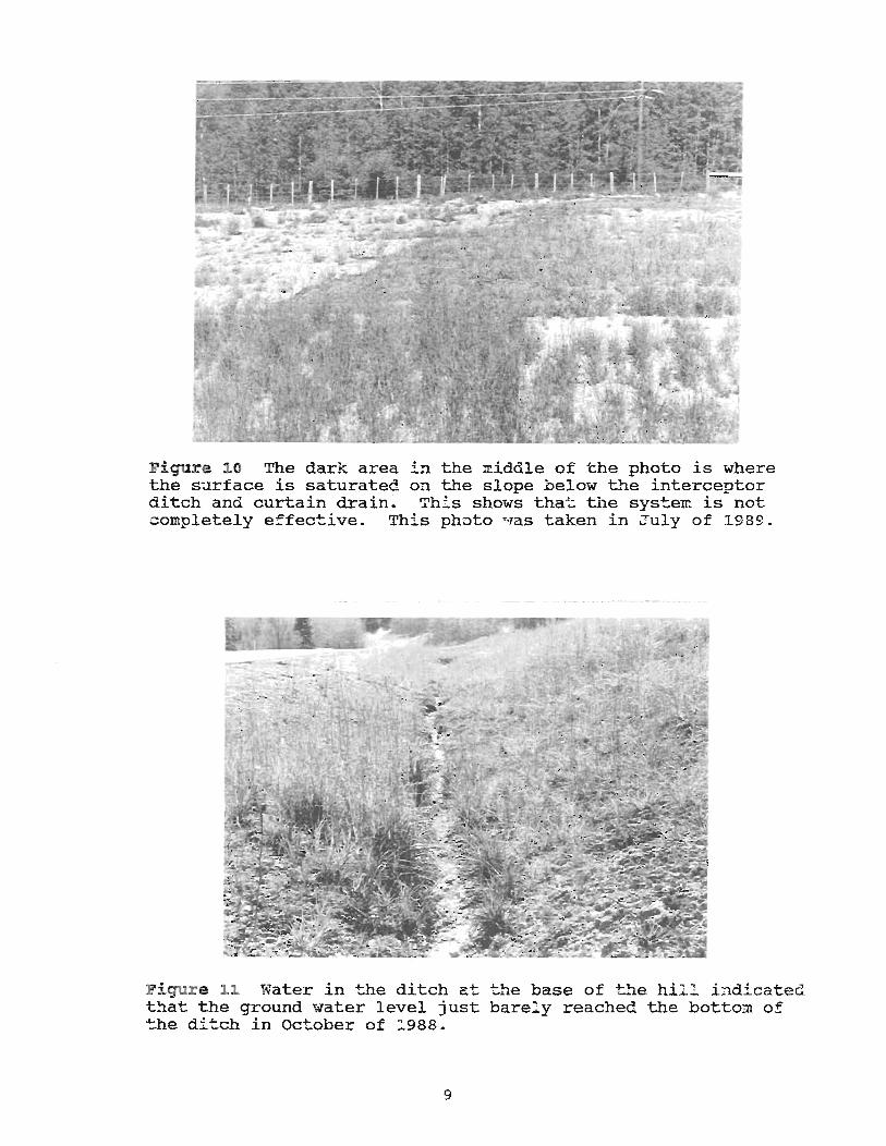
Figure 10 The dar}t area in the :n.iddle of the photo is where the surface is saturated on the slope below the interceptor ditch and curtain drain~ This shows that tile sys~em is not completely effective. This photo was taken in July of 1989.
Figur e 1.1 Water in the ditch at the base of t.'1e hill i ndicated that the ground water level just barel y reached the bottom of t he ditch in October of 1988.
9
I:: l~ay of 1990 F Tl:e s?.:rface of the gro~nd t'las mos::'ly dr"lJ. Some 0: the area downhil l and adjacent to the small channel at the top of the hill was wet. This surface moisture did not, however, extend to the mois~ure probe holes on the do~~ill side of the curtain drains.
In 1991 there 't'Jas a l ittle bit more precipitatior:. No field trip was taken to the site that yea~, but according to reports from the maintenance forces, there -:;'lere not any probleI:s witc instability on the slope.
Slight b~lging on the slope occurred sometime during 1992 or 1993.
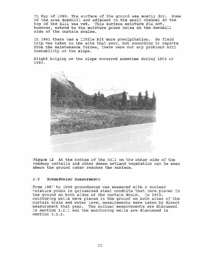
Fi~~re ~2 At the bottom of the hi~l on t~e other side o~ the roadway cattails and other dense wetland vegetation can be seen where the ground ,.,:ater reaches the surface.
3 . 2 .3roundwa.ter .. ~easurement
From 1987 to 1990 groundwater \;as measured with a nuclear moisture probe in galvanized steel conduits ::'hat ~e~e placed in the ground on both sides of the curtain drain. In 1993, no~itoring wel:s were placed in the gro~nd on both sides of the curtain drain and water level ~easu~ements were taken by direct neasurereent that year. The nuclear measu~ements are discussed in section 3.2.: and the monitoring wells are discussed in section 3.2.2.
10
3.2.1 Moisture Tubes and Nuclear Moisture Measurement
A down-hole nuclear moisture probe was used . from 1987 to 1990 to measure soil moisture content. Based on the results from this testing, the top of the "saturated zone" could roughly be found. This saturated zone consists of the water table and the capillary fringe above it.
3.2.1.1 Theory and Method
The neutron logging device used on this project consisted of an Americium 241 - Beryllium radioactive source and a detector device within a stainless steel shaft attached to a 4.9 meter (16 foot) cable which enabled the shaft to be lowered into the moisture tubes. The source emits neutrons. The emitted neutrons are slowed and scattered by collisions with nuclei of hydrogen atoms. The detector counts the number of neutrons that are slowed and reflected. Thus with this device, the higher the number of "slow" neutrons detected, the higher the hydrogen content in the soil. In the ground, almost all of this hydrogen is in the form of water. Thus the neutron count can be used to determine the water content. 3
Within the saturated zone, higher neutron counts indicate more P9rous soils, since these soils have the capacity to hold more water. Above the water table, the neutron-logging equipment can be used to measure the moisture content, but not the porosity or percent of voids filled. 4
The standard count is obtained by taking readings at the site with the probe inside its protective sleeve. This reading is approximately the same as that obtained in a soil with 10 pcf of water. Higher readings indicate higher moisture contents. Where rio reading is given, readings were considered invalid.
11
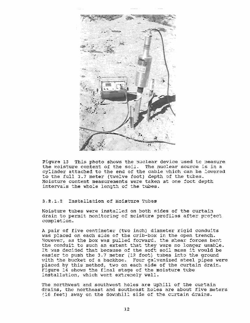
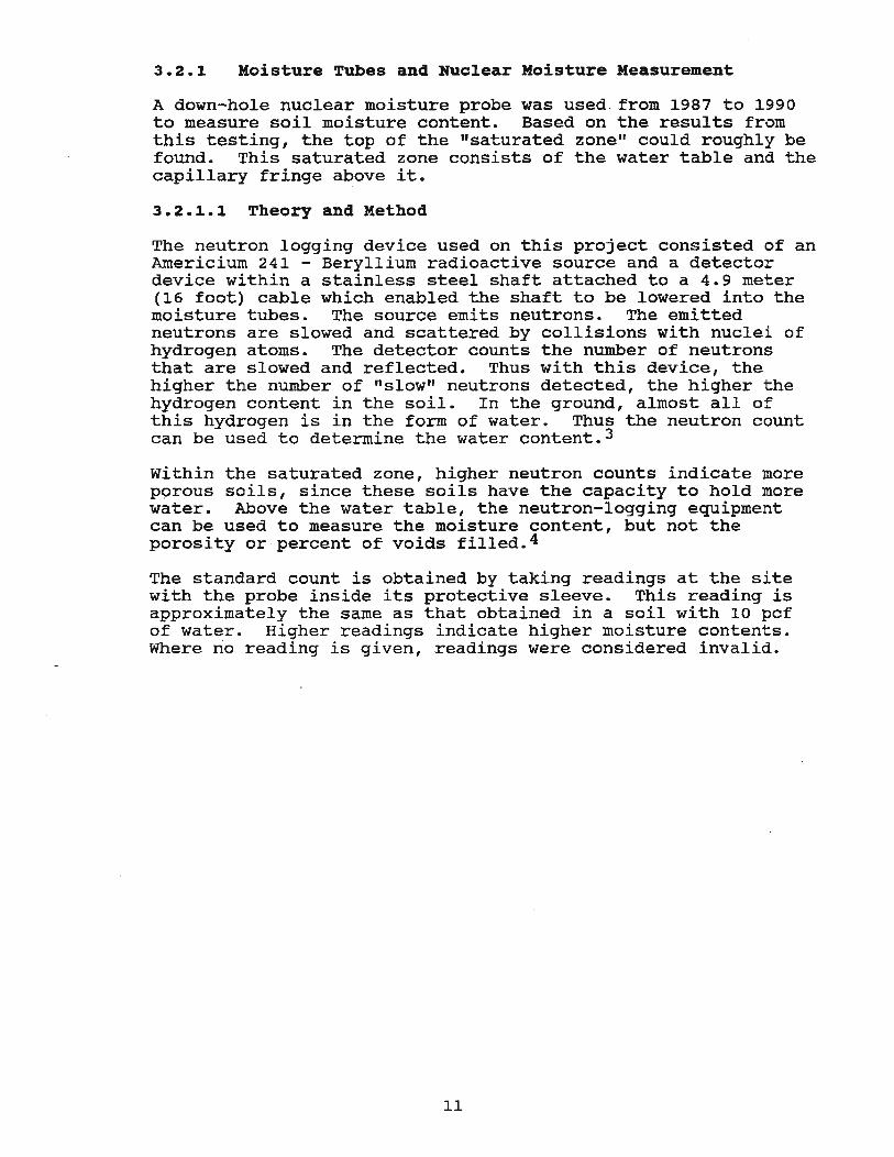
Figure 13 This photo shows the nuclear device used to measure the ~ois~ure content of the soil. The nuclear source is in a cy ... inder attached to the end of the cable 'tvhich can be Im-rered to the full 3.7 meter (twelve foot) dep~~ of the tubes. Moisture content measurements were taken at one ::oot depth intervals -the whole length of the tubes.
3 . 2 • 1 . 2 IllS"talla.'tion of Mois tur.! T lbes
Noisture tubes were installej on both sides of the curtain drair:. to per::nit l'lon:'toring of mcistl.!re pro::':'les after p::::-ojec·= compl etion.
A pair of five centimeter (t~o inch) diaEeter rigid conduits was placed on each side 0:: the crib-box in the open trench. Hmc;ever, as tb.e box was pulled fonrard~ the sr:ear :::orces bent the conduit to such an extent ~~at they were no longer usable. It das deciaed that because of the soft soil mass it would be easier to push the 3.7 meter (12 foot) tubes into the ground with the bucket of a backhoe. Four galvanized steel pipes were placed by this method, two on each side of the curtain drain. Figure 14 shows the final stage of tee moisture tube installation, which we~t extre~ely well.
The northwest and southwest holes are uphill of the curtain drains, the northeast and southeast holes are about five meters (1.6 feet) a",!ay O!l the aovrnhil:!. side 0::: t!le c~rtain drains.
12
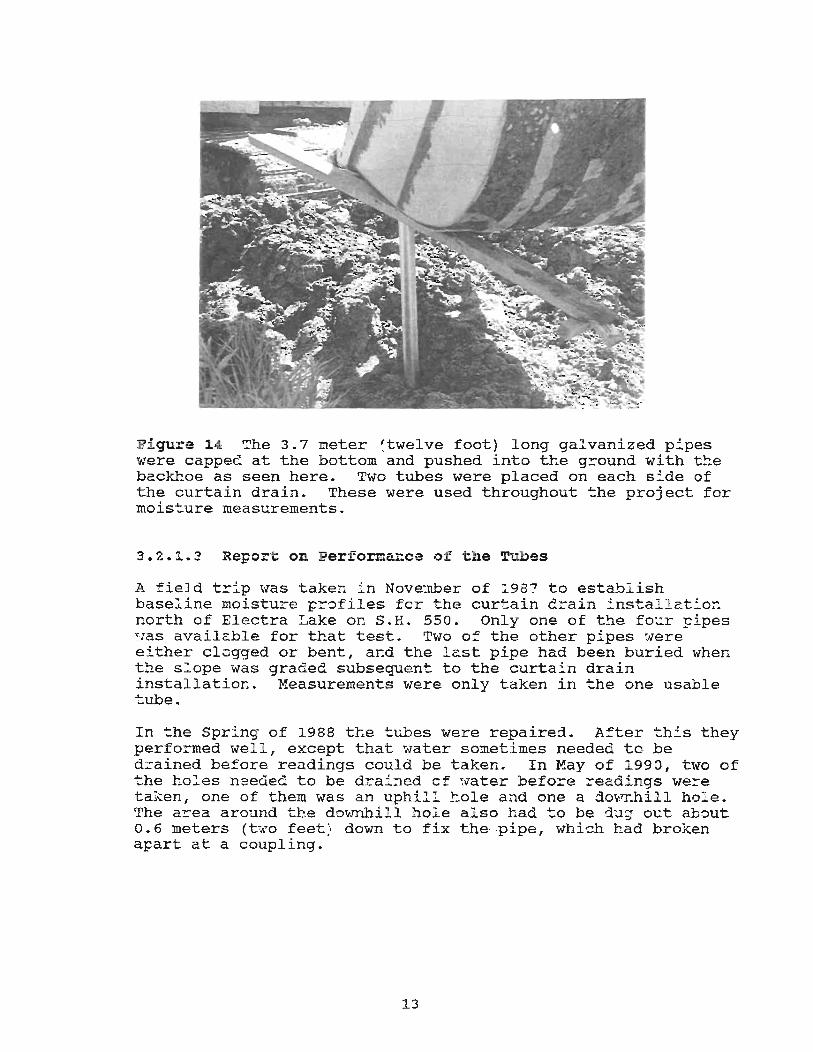
Figure 14 The 3.7 meter (twelve foot) long galvanized pipes were cappe~ at the bottom and pushed into the ground with t~e backhoe as seen here. Two tubes were placed on each side of the curtain drain. These were used throughout ~he project for mois~ure measurements.
3.2.l.3 Report on Performance o f the Tubes
A field t!:"ip t;'/as taken in November of 1987 to establish baseline moisture pr:>files fer the curtain drain install at:'or: north of Electra Lake or. S.H. 550. Only one of the four ~ipes Has available for that test. Two 0:: the other pipes were either clcgged or bent, and the last pipe had been buried when the s~ope was graded subsequent to the curtain drain installatior.. Measurements were only taken in the one usable tube.
In the Spring of 1988 the t~es were repaired. After this they performed well , except that "".qater sometimes needed to be drained before readings could be taken. In May of 1990, two of the hO::"es n'seded to be drained of ~>later befo:::-e readings were taken, one of them was an uphill hole and one a dO~1J:.hill hol e. The a!:'ea around the dOvmhill ho:e also had to be d:.lg out about 0.6 meters (tir.·o feet ) down to fix the ,pipe , whi-::h had broken apart at a coupling.
13
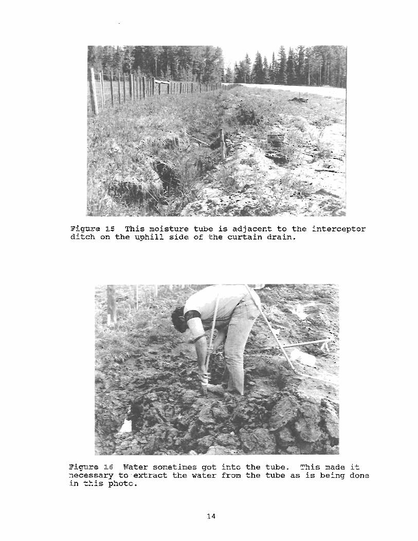
Fi gure 15 This moisture tube is adjacent to the interceptor di"tch on the uphill side of 'the curtain drain.
F:i.qur e ~6 Nater so:reetimes got into the tube . This made i"t necessary to extract the water from the tube as is being done i n this photo.
l4
3.2.1.4 Report on results of testing
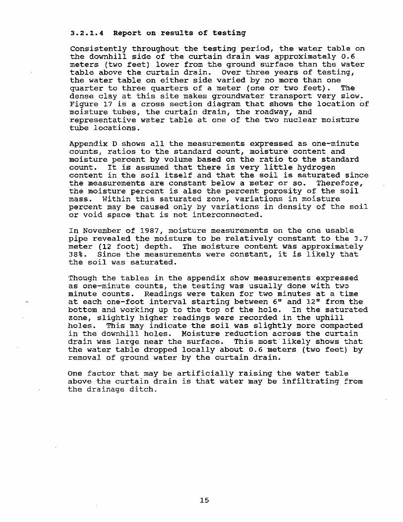
consistently throughout the testing period, the water table on the downhill side of the curtain drain was approximately 0.6 meters (two feet) lower from the ground surface than the water table above the curtain drain. Over three years of testing, the water table on either side varied by no more than one quarter to three quarters of a meter (one or two feet). The dense clay at this site makes groundwater transport very slow. Figure 17 is a cross section diagram that shows the location of moisture tubes, the curtain drain, the roadway, and representative water table at one of the two nuclear moisture tube locations.
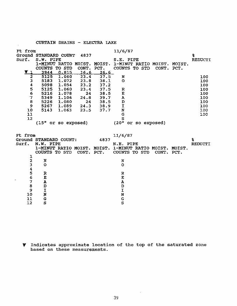
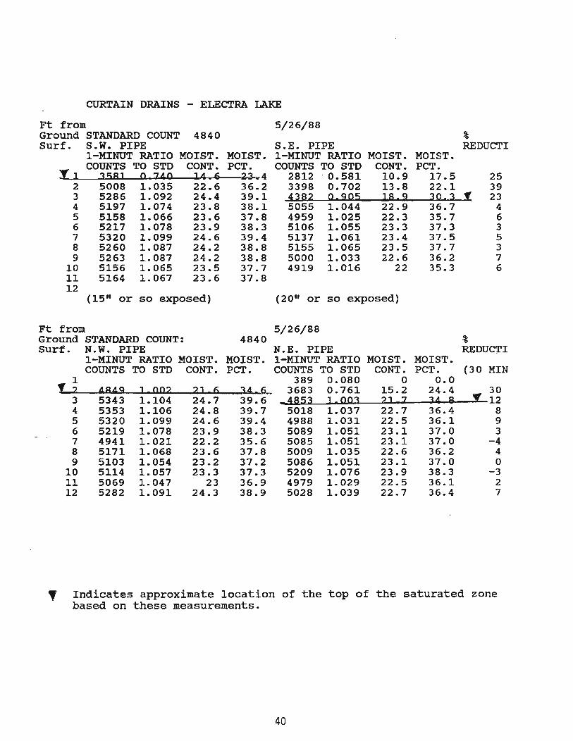
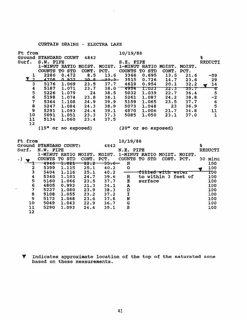
Appendix 0 shows all the measurements expressed as one-minute counts, ratios to the standard count, moisture content and moisture percent by volume based on the ratio to the standard count. It is assumed that there is very little hydrogen content in the soil itself and that the soil is saturated since the measurements are constant below a meter or so. Therefore, the moisture percent is also the percent porosity of the soil mass. within this saturated zone, variations in moisture percent may be caused only by variations in density of the soil or void space that is not interconnected.
In November of 1987, moisture measurements on the one usable pipe revealed the moisture to be relatively constant to the 3.7 meter (12 foot) depth. The moisture content was approximately 38%. Since the measurements were constant, it is likely that the soil was saturated.
Though the tables in the appendix show measurements expressed as one-minute counts, the testing was usually done with two minute counts. Readings were taken for two minutes at a time at each one-foot interval starting between 6" and 12" from the· bottom and working up to the top of the hole. In the saturated zone, slightly higher readings were recorded in the uphill holes. This may indicate the soil was slightly more compacted in the downhill holes. Moisture reduction across the curtain drain was large near the surface. This most likely shows that the water table dropped locally about 0.6 meters (two feet) by removal of ground water by the curtain drain.
One factor that may be artificially raising the water table above the curtain drain is that water may be infiltrating from the drainage ditch.
15
I-' 01
RIGHT OF WAY FENCE
'\
CROSS-SECTION OF CURTAIN DRAIN 8T A TION 434+50
DRAINAGE CHANNEL l tvIOlSTURE TUBES /. ~ t LAND SURFACE
~
Figure 17 Moisture tube diagram
ROAD
r-
3 . 2 . 2 Mo:...i toring We l ls
Monitorinc; vlells T~Jere installed at this si'te in July of 1.993 to verify the inferences of the nuclear logging gages. One set was instal:ed near the moisture tubes at station 434+50. A second set was installed 45 meters 'l50 feet) to the south (about 30 meters (100 feet) south of the southern moisture tubes) .
When the wells were drilled, no \-later was found in the bottom of the we: ls, although the clayey soil was wet. Smal l stones that lJere dropped into the well ltade a thud as they hit the bottom. This situation was temporary. Within a few days, a few ~eters of water had risen in the wells. This experience shows how slowly water moves through dense clayey soil .
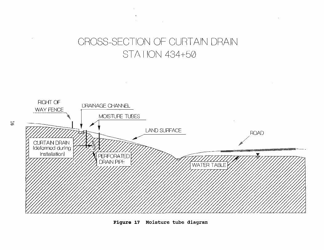
Fi~~re i s The cohesiveness of the c.ay was demonstrated by the way strips of mud were peeled off the auger during the i~stallation of the ~onitoring wells.
After about t~jO weeks , the i.·7ate~ leve]. had stabil ized. r:'he sst of wells insta_Ied ~ear the moisture tubes at station 434+5G verified th·g inferred 'Nater table level. The :.yater table in the wells was about 0.6 meters (two feet, lower than the saturated. zone found by the nuclear gages. The ~yells measure the true potentiometri c surface (level to which water rises in a tightly cased well; or total head), whereas the saturated zone which was neasured by the nuclear gages includes the capillarz fringeS which in this case is assumed to be about 0. 6 neters (two feet ) al;>ove . the water table. Table I shov,~s the nonitoring well measurements.
l7
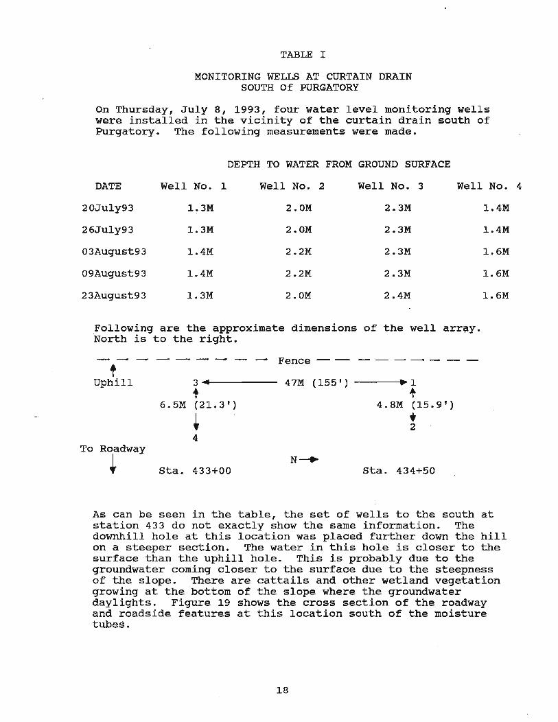
TABLE I
MONITORING WELLS AT CURTAIN DRAIN SOUTH Of PURGATORY
On Thursday, July 8, 1993, four water. level monitoring wells were installed in the vicinity of the curtain drain south of Purgatory. The following measurements were made.
DEPTH TO WATER FROM GROUND SURFACE
DATE Well No. 1 Well No. 2 Well No. 3 . Well No.
20July93 1.3M 2.0M 2.3M 104M
26July93 1.3M 2.0M 2.3M 1.4M
03August93 1.4M 2.2M 2.3M 1.6M
09August93 1.4M 2.2M 2.3M 1.6M
23August93 103M 2.0M 2.4M 1.6M
Following are the approximate dimensions of ·North is to the right.
the well array.
--- ---- ..- Fence -- ---- - -t
Uphill 3 • 47M (155' ) ~1
~ .,. 6.5M (21.3') 4.8M (15.9')
+ • 2 4
To Roadway
~ N~
sta. 433+00 Sta. 434+50
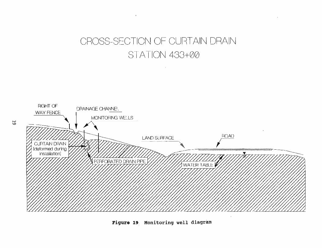
As can be seen in the table, the set of wells to the south at station 433 do not exactly show the same information. The downhill hole at this location was placed further down the hill on a steeper section. The water in this hole is closer to the surface than the uphill hole. This is probably due to the groundwater coming closer to the surface due to the steepness of the slope. There are cattails and other wetland vegetation growing at the bottom of the slope where the groundwater daylights. Figure 19 shows the cross section of the roadway and roadside features at this location south of the moisture tubes.
18
4
I-' 1.0
CROSS-SECTION OF CURTAIN DRAIN
ST A TION 433+00
RIGHT OF DRAINAGE CHANNEL
WAY FENCE ~ MONITORING WELLS \ /
!;>777~
LAND SURFACE ROAD
;-
Pigure 19: Monitoring well diagram
3.3 pi p e Flow
The curtain drain system on this projec~ was designed t~ collect some infilt.rated surface flows as vle l l as ground lva'cer and channel this water aloGg the perforated drain pipe to a cross culvert. Figure 8 on page 7 shows a Eanhole during constructi on where t~o curtain drain systems feed into the cross culvert.
It was expected that with t~e great amount of moisture in the area during construction, there sho~ld have been an increasing amount of flow from the curtain drain system as the project progressed. This was not the case during the two-day period of construc~ion that was observed. Subsequer.t phone conversations with the project engineer revealed that the flow did not i ncrease. A wel l r.ad to be drilled for the adjoining property owner to provide the water to his property that he lost due to the construction project. It. had been hoped that the water from the curtain drain would provide the necessary water.
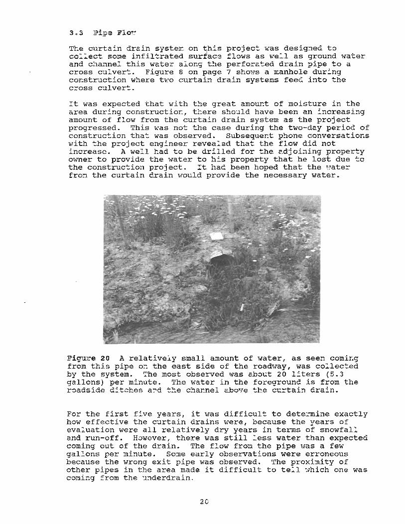
Figur e 20 A relatively small amount of water , as seen coming from this pipe or. the east side of the roadway, was collec~ed by the system. The most observed 'f,ITas about 20 l i ters (5.3 gallons) per mi nute. The water in the foreground is from the roadside ditches a~d t~e channel above the curtain drain.
For the first five years, it was difficult to determine exactly how effective the curtain drains were, because the years of eval uation were all relatively dry years i n terms of snowfal l and run-off. However, there was still _ess water than expected coming out of the drain. Th.e flow from. the pipe "las a few gal l ons per minute. Some early observations were erroneous because the wrong exit pipe was observed. The proxi~ity of other pipes in the area made it difficult to te~l which one was coming from the underdrain.
20
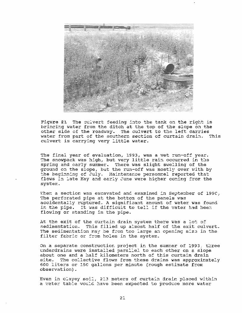
Figure 21. The ::ulvert feeding :'nto the tank on the right is bringi~g wate~ from the ditch at the top of the slope on the other side of the roadway. The culvert to the left carries water from part of the southern section of curtain drain. This culvert is carrying very little water.
Ths final year of evaluation, 1993, was a wet ~un-off year. The snowpack was high, but ve-::y little rai!1 occurred in the spring and early SUlmner. There was slight svlelling of the ground on the slope, but the run-off was mostly over with by the beginn:'ng of July. Maintenance personr.el reported that flows in late Kay a~d early June were higher coming from the system.
Ehen a section was excavated anci examined in septe!lber of 1990, The perforated pipe at the bottom of the panels was accidentally ruptured. A significant amount of water was found intl1e pipe. :t ~Nas difficult to tell if the ~:ater ~lad been flowing or standing in the pipe.
At the exit of the curtain drain system there was a lot of sedimentation. This filled up almost half of the exit culvert. The sedimentati::m nay be froD t.oo large a:l open:"ng size in .... he filter fabric or f~om holes in the system.
On a separate construction project in the sum:mer of 1993 , three underdrains were installed paral~el to each other on a slope about one and a half kilometers north of this curtain drain site. The collective flows from these drains was approxioately 600 liters or 150 gallons per minute (rough estimate from observation) •
Even in c:ayey soil , 2!3 meters of curtain drain placed within a ~ater table would have been expected to produce more water
21
than was obtained on this project. The low flow from the curtain drain that occurred throughout the evaluation period could be a combination of several factors. These' include: the limited hydraulic .conductivity of the clayey soil, collapsing of the panels during installation, lowering of water table due to dry years, or clogging of the filter fabric, though the latter did not appear to be the case upon excavation. It is also possible that the filter fabric was not appropriate for the · soil type to most efficiently transport water without clogging.
.. • EXCAVATION
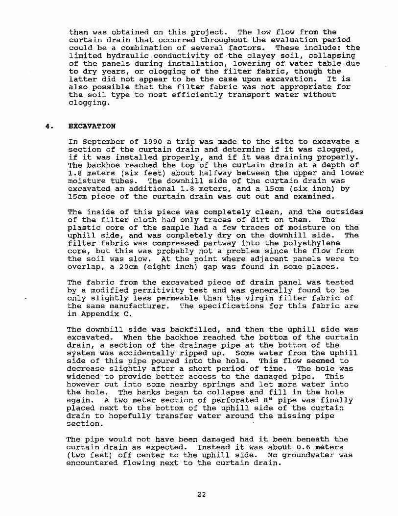
In September of 1990 a trip was made to the site to excavate a section of the curtain drain and determine if it was clogged, if it was installed properly, and if it was draining properly. The backhoe reached the top 'of the curtain drain at a depth of 1.8 meters (six feet) about halfway between the upper and lower moisture tubes. The downhill side of the curtain drain was excavated an additional 1.8 meters, and a 15cm (six inch) by 15cm piece of the curtain drain was cut out and examined.
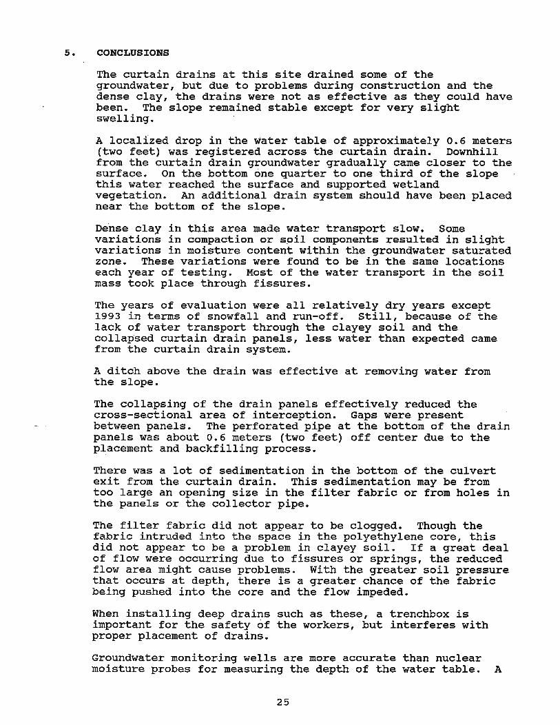
The inside of this piece was completely clean, and the outsides of the filter cloth had only traces of dirt on them. The plastic core of the sample had a few traces of moisture on the uphill side, and was completely dry on the downhill s·ide. The filter fabric was compressed partway into the polyethylene core, but this was probably not a problem since the flow from the soil was slow. At the point where adjacent panels were to overlap, a 20cm (eight inch) gap was found in some places.
The fabric from the excavated piece of drain panel was tested by a modified permitivity test and was generally found to be only slightly less permeable than the virgin filter fabric of the same manufacturer. The specifications for this fabric are in Appendix c.
The downhill side was backfilled, and then the uphill side was excavated. When the backhoe reached the bottom of the curtain drain, a section of the drainage pipe at the bottom of the system was accidentally ripped up. Some water from the uphill side of this pipe poured into the hole. This flow seemed to decrease slightly after a short period of time. The hole was widened to provide better access to the damaged pipe. This however cut into some nearby springs and let more water into the hole. The banks began to collapse and fill in the hole again. A two meter section of perforated 8" pipe was finally placed next to the bottom of the uphill side of the curtain drain to hopefully transfer water around the missing pipe section.
The pipe would not have been damaged had it been beneath the curtain drain as expected. Instead it was about 0.6 meters (two feet) off center to the uphill side. No groundwater was encountered flowing next to the curtain drain.
22
since the clay is =a~rly uniform ~~ the very _ittl e water pe~eates the ground. subsurface ~ater transport in this area fiss~res in the clay formation.
curtain drai~ area , The ma;oritv of t~e
~ ~
appears to come through
Fi~~re 22 In September of 1990, a section of the drain was excavated with a backhoe and examined. The top of the curtain drain was found at a depth of almost two meters (six feet) . The water in this photo at the bottom of the trench is due to the accidental cutting into the perforated pipe.
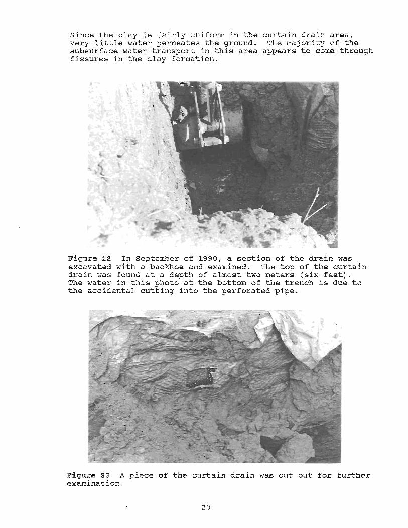
Fiyure 23 A piece of the curtain drain was cut out for further examination .
23
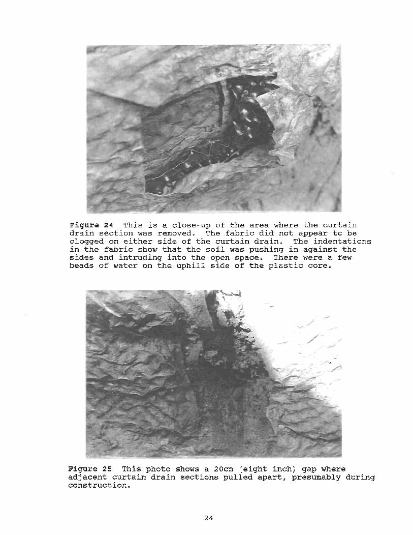
Figure 2 4 This is a close-up of ~he area where the curtain drain section was removed. The fabric did not appear to be clogged on either side of the curtain drain. The indentations in the fabric show that the soil was pushing in against the sides and intruding into the open space. 'lhere were a few beads of water on the uphil l side of the plastic core.
Fi~~r.e 2S This photo shows a 20c~ (eight inch) gap where adjacent curtain drain sections pulled apart, presumably during construction.
24
5. CONCLUSIONS
The curtain drains at this site drained some of the groundwater, but due to problems during construction and the dense clay, the drains were not as effective as they could have been. The slope remained stable except for very slight swelling.
A localized drop in the water table of approximately 0.6 meters (two feet) was registered across the curtain drain. Downhill from the curtain drain groundwater gradually came closer to the surface. On the bottom one quarter to one third of the slope this water reached the surface and supported wetland vegetation. An additional drain system should have been placed near the bottom of the slope.
De"nse clay in this area made water transport slow. Some variations in compaction or spil components resulted in slight variations in moisture content within the groundwater saturated zone. These variations were found to be in the same locations each year of testing. Most of the water transport in the soil mass took place through fissures.
The years of evaluation were all relatively dry years except 1993 in terms of snowfall and run-off. still, because of the lack of water transport through the clayey soil and the collap"sed curtain drain panels, less water than expected came from the curtain drain system.
A ditch above the drain was effective at removing water from the slope.
The collapsing of the drain panels effectively reduced the cross-sectional area of interception. Gaps were present between panels. The perforated pipe at the bottom of the drain panels was about 0.6 meters (two feet) off center due to the placement and backfilling process.
There was a lot of sedimentation in the bottom of the culvert exit from the curtain drain. This sedimentation may be from too large an opening size in the filter fabric or from holes in the panels or the collector pipe.
The filter fabric did not appear to be clogged. Though the fabric intruded into the space in the polyethylene core, this did not appear to be a problem in clayey soil. If a great deal of flow were occurring due to fissures or springs, the reduced flow area might cause problems. With the greater soil pressure that occurs at depth, there is a greater chance of the fabric being pushed into the core and the flow impeded.
When installing deep drains such as these, a trenchbox is important for the safety of the workers, but interferes with proper placement of drains.
Groundwater monitoring wells are more accurate than nuclear moisture probes for measuring the depth of the water table. A
25
problem .that is evident with both types of ground water measurement is that when they are installed in clayey soil such as this, water migrates very slowly, so rapid changes in moisture may not be recorded instantly in the wells. A pressure transducer or similar device linked to a data logger that regularly records the depth of water in the wells is helpful to· avoid missing changes in water levels. ·A flow meter at the outlet of the system would also make measurement easier, more accurate, and continuous.
When using the nuclear moisture probe method, the moisture tubes can be unreliable and difficult to work with because they can get water in them, which precludes taking readings, and
-they have a tendency to separate at the couplings.
6. IMPLEMENTATION
Geocomposite drains are currently used on five to ten CDOT projects a year. COOT now only uses these types of systems next to retaining walls.
Because of the collapsibility of the drains and the danger associated with instability of the trench walls, it is better to install sections shallower. Rather than install one curtain drain to a depth of 3.7 meters (twelve feet), it is easier and probably more effective to install two French drains parallel to depths of i.5 to 2 meters if they are properly spaced. This can be done because a lowered water table will rise again toward the surface downhill from the first drain. The installation should coincide with the lowest ground water level of the year if possible. I advise against using geocomposite drains in slope stability applications.
Care should be taken to avoid collapsing the drain panels during installation and backfill. The panels should overlap slightly so that gaps do not form between panels. Safety should be the most important item for the contractor during construction. Before doing an installation of this type of drain in the future, trench side stability needs to be determined. If the drains cannot be installed without the aid of a trenchbox, alternative ways to address the problem need to be considered. Using the trenchbox method it is virtually impossible to get the geocomposite drain installed at the proper vertical and horizontal alignment and overlaps.
When specifying geocomposite drains on a project it is important to specify a fabric which is matched to the soil conditions to avoid clogging or excessive sedimentation in the system. If possible, exit culverts should be steeper to provide enough energy in the flow to remove sedimentation from the pipe. Current standard plans and specificatiops are shown in Appendix E.
A drainage ditch dug at the top of a slope such as on this project can be very effective at removing moisture and keeping the surface of the slope relatively dry. This water must be
26
transported away from the slope to avoid re-infiltration or erosion of the slope.
Groundwater monitoring wells should be used instead of nuclear moisture gages for ease of measurement and accuracy if all that is needed is the groundwater level or potentiometric surface. These wells are more common and less expensive than the nuclear method.
The use of a flow meter to continuously measure the flow from the system, and a series of monitoring wells to get a more detailed profile of the groundwater elevation is recommended to more accurately determine the effectiveness of the drain systems.
Cost data from this project is presented in Appendix B •
. 27
FOOTNOTES
1. Chapter 300 - Geometric Cross Section, ROADWAY DESIGN MANUAL, state of Colorado, Department of Highways, Division of Highways, Denver, Co., 1990, P. 3-3
2. IBID
3. Fetter, C.W., APPLIED HYDROGEOLOGY, Second Edition, Merrill Publishing Company, Columbus, Ohio, 1988, p. 517
4. IBID
5. IBID, p. 91
28
BIBLIOGRAPHY
Chapter 800 - Drainage, ROADWAY DESIGN MANUAL. State of Colorado, Department of Highways, Division of Highways. Denver, Co. 1990.
Fetter, C.W. APPLIED HYDROGEOLOGY, Second Edition. Merrill Publishing Company. Columbus, Ohio. 1988.
Kraemer, S.R. and Smith, A.D. GEOCOMPOSITE DRAINS, Vol I: Engineering Assessment and preliminary Guidelines. FHWA. McLean, Virginia. October, 1986.
29
APPENDIX A
PLANS AND SPECIFICATIONS FROK PROJECT ·CXFC 20-0550-21
30
(
( .
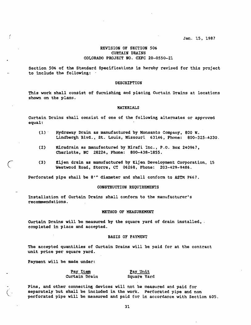
REVISION OF SECTION 506 CURTAIN DRAINS
COLORADO PROJECT NO. CXFC 20-0550-21
Jan. 15, 1987
Section 506 of the Standard Specifications is hereby revised for this project to include the following: .
DESCRIPTION
This work shall consist of furnishing and placing Curtain Drains at locations shown on the plans.
HATERIALS
CUrtain Drains shall consist of one of the following alternates or approved equal:
(1) ' Hydraway Drain as manufactured by Monsanto Company, 800 N. Lindbergh Blvd., St. Louis, Missouri 63146, Phone: 800-325-4330.
(2) Hiradrain as manufactured by Mirafi Inc., P.O. Box 240967, Charlotte, NC 28224, Phone: 800-438-1855.
(3) Eljen drain as manufactured by Eljen Development Corporation, 15 Westwood Road, storrs. CT 06268, Phone: 203-429-9486.
Perforated pipe shall be 8' II diameter and shall conform to ASnt F667.
CONSTRUCTION REQUIREMENTS
Installation of curtain Drains shall conform to the manufacturer's recommendations.
METHOD OF MEASUREMENT
Curtain Drains will be measured by the square yard of drain installed, , completed in place and accepted.
BASIS OF PAYMEbIT
The accepted quantities of CUrtain Drains will be paid for at the contract unit price per square yard.
Payment will be made under:
Pay Item Curtain Drain
Pay Unit Square Yard
Pins. and other connecting devices will not be measured and paid for separately but shall be included in the work. Perforated pipe and non perforated pipe will be measured and paid for in accordance with Section 605.
31
740
'~o
, ...
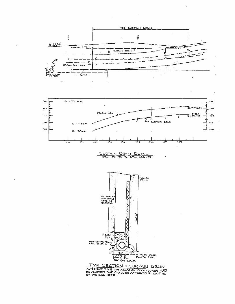
o ... ... I' 1ft ... ... " ____ --------~~O~------__ _ R.O.N' '--I ----po-=-~~~~~-----=M~A~~'~LE~ ~-- -,-. - - =-t" .--. - ---===r= - II -~\.,-. ____ --·w CUItT .... ~:r .... NJ . ".____'- ~ ___ j __ __
--~-,.----- ,.., --- .".. -..---.---------.----- --, .. ~:-,;;-;.;;.3f-r---=---::--==---~===---;~ -_ .. --
f>1 ... 2. ". MIN,
T':, , , '.
£""''''''TEb M"TEIl~~ 1.eE:~ ... !Ii aA.C"'~It..1..
., o .~
TYP. SEC.TION '" CU12TAII\J DK'AIN AI.:re.cNATe i'tl"'!! IW"-'TAI..\.A'iICW I"':Z:OGeo;OUR:E:'5 MA...., e~ N.J.OWeo. ~ <7tiAl..L ese "r"P~cO II.J WI:'ITlfoJC. '0"'1 nt~ e.w.c:.II.P~tI:..
_.-----. ".U.s . I EL.~
'''0
"0
"100
"
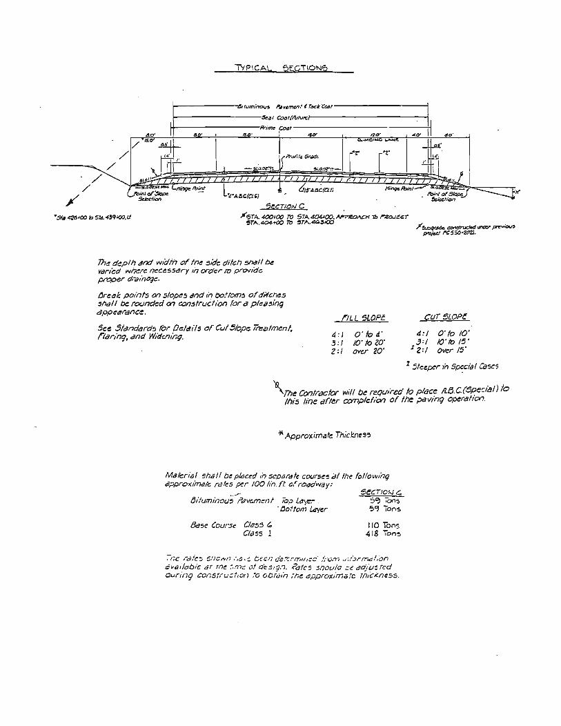
TYPICAL 5t;CTION,?
!----------."ifumi'''',,,. ,o4vemenf t T«" "Co.J/--------------!
~-------------~.,c~f(ru~·}~-------------------~ !+----------------Prim. C04'---------------------~
/ /
/
c· IMl ~
"0- 4..,'
/ / 'IS" IUlC.(CLI} Ifinqc lbinl
'CCT/ONe
)I"~TA. 400100 TO 5TA404100. "';'~H :;:, ~t:~r ~TA,4Of..oo ~ ~TA.4~3000
7h~ clt:pth at?d wKiih of tn~ side ditch snaIl ~ Vdrl(:d INr~re l7t:ct:SSdry In order 1'0 pre;Nio'c proper (/''aliIQqt:,
jjrt:~1: poinfj (Y) ~/O~5 dnd In Oo!tom:J of ditches ~ha" be roundt:d 0'7 consfr/Jcf;Ofj for a plcilsinq dppcarance.
See Standard!! tOr De/clI'ls ofCt.Ji5/0pe Trea/ment, rtar/nq. and W/duu'ng.
nLL SLOPe.
4 :1 0'104' 3 :1 /0' to ZO' Z:I Over 20'
cur5LOPe
4:/ 0' to /0' 3:/ /0'/0 /5'
12:/ O~r /5'
I !tt:eper 1;' SPI:,cial Ca~5
\rn~ Con/rae/or will be required to plac7 A,fJc.(OpeciaJ) to f/7i:s line arter ccmpielian of the pdVlng opera/Ion.
'* Approximate Thjdl1~s,}
Material ~hQII be plQc~d /n sCf)ardfe COIJrse'5 at tile fo/lo~Vlnq approximate rates ~r 100 lin. rt. 0/ roadway:
5ECT/O~ c. 5':) 'ons ':>~ Tons
fji/uminou;"'"PavGmcrlI iop La~e:- . '&ttom lAVer
&sc Course CliJ55 " C/t!J!S 1
110 Tons 418 T~"5
-:liC ,"d'll~ SlJC".,1i ,"i"a· ~ b"C/l ,ie:t ."mi/,~:::· / , 0.71 ,r, r":;rmd.',On ,;vatletoie ar mr:. ;.m:: vi a'e::"9.'J, i'otc'S snoc.lio .;;c;::o'lu:;tcd ol.Jring constr/Jct,o/l ;0 ocrut'n ,-he ,;pprox/more Th"cj(ne~5,
APPENDIX B
COSTS OF THIS CURTAIN DRAIN PROJECT
34
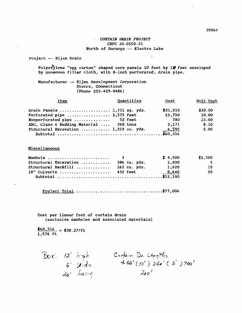
Project -- Eljen Drain
CURTAIN DRAIN PROJECT CXFC 20-0550-21
North of Durango -- Electra Lake
2006r
polye~Ylene "egg carton" shaped core panels 10 feet by III feet enveloped by nonwoven filter cloth, with 8-inch perforated, drain pipe.
Manufacturer -- Eljen Development Corporation storrs, Connecticut (Phone 203-429-9486)
Quantities
Drain Panels ..............•.•.... 1,751 sq. yds. $35,010 Perforated pipe ....•..........•.. 1,575 feet 15,750 Nonperforated pipe ........•.•.... 52 feet 780 ABC, Class 6 Bedding Material. ... 268 tons 2,171 structural Excavation ............ 1,319 cu. yds. 6,595
Subtotal •..................•..........•............. $60,316
Miscellaneous
Manhole ...•...................... 3 $ 4,500 Structural Excavation ............ 386 cu. yds. 1,930 Structural Backfill.............. 162 cu. yds. 1,620 18" CuI verts .......•... . ... .....• 432 feet 8.640
Subtotal ...........................•..............•. $12 ,190
Project TotaL ............•............•........•. $77,006
Cost per linear foot of curtain drain (exclusive manholes and associated materials)
$60.316 = $38.27/ft 1,576 ft
.f
.. I
~:''l '~0 I
I ~
!.)!d~ !
,i...Aj ; ~~ ~1· §
C II vf~/~ Vwi'. L~1 't4s 4. ~! ( 33' ) 2~ · ( ~! ) 700 J
ho'
Unit Cost
$20.00 10.00 15.00
8.10 5.00
$1,500 5
10 20
APPENDIX C
PRODUCT SPECIFrCATIONS
36
. / I I
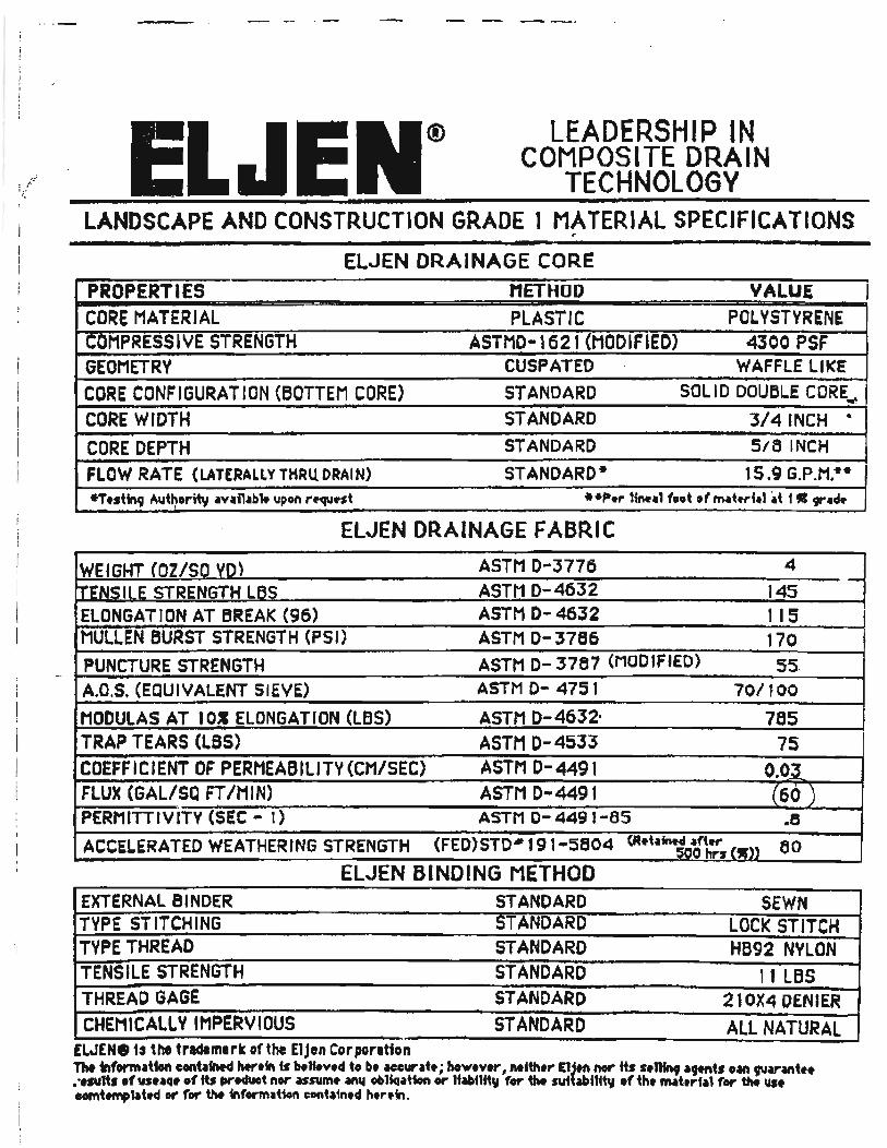
® LEADERSHIP IN COMPOSITE DRAIN
TECHNOLOGY LANDSCAPE AND CONSTRUCTION GR.ADE 1 MATERIAL SPECIFICATIONS
r - -ElJEN DRAINAGE COR.E PROPERTIES METHOD VALUE CORE MATERIAL PLASTIC POLVSTVRENE ~OMPRESS I 'IE STRENGTH ASTMD-1621 (MODIFIED) 4300 PSF GEOMETRY CUSPATED WAFFLE LIKE
CORE CONFIGURATION (BOTTEM CORE) STANDARD SOLID DOUBLE CORE. ... CORE WIDTH STANDARD 3/4 INCH ~
CORE DEPTH STANDARD 5/5 INCH
FLOW RATE (LATERALLY THRU DRAIN) STANDARD- 15.9 G.P.M!* -Ttstfnt ""thorit, ~vai1ab" upon r.-q\l.,t **p.,. 11n.-11 •• t .f 1M~.,.1.1 ~t t C 91" ••
ELJEN DRAINAGE FABRIC
WEIGHT (OZ/SO VO) ASTM D-3776 4
f.t.N:sllE STRENGTH LBS ASTM 0-4632 145 ELONGATION AT BREAK (96) ASTM 0-4632 1 15 MUllEN BURST STRENGTH (PSI) ASTM 0-3786 170 PUNCTURE STRENGTH ASTM 0- 3767 (MODIFIEO) S5 A.D.S. (EQUIVALENT SIEVE) ASTM 0- 4751 70/'00 MOCUlAS AT lOS ELONGATION (LBS) ASTM D- 4632' 765 TRAP TEARS (LBS) ASTM 0-4533 75 COEFFICIENT OF PERMEABILITY (CM/SEC) ASTM 0-4491 O.O.} FLUX (GAL/SQ FT /MIN) ASTM 0-4491 (60 ) . PERMITTIVITY (SEC'" 1) ASTM 0- 449 1-65 .5
ACCELERATED WEATHERING STRENGTH (FED)STO·l 9 1-:5804 (R·t.I~o1l::s (w)) eo ELJEN BINDING METHOD
EXTERNAL B I NOER STANDARD SEWN TYPE STITCHING STANDARD LOCK STITCH TYPE THREAD STANDARD HB92 NYLON TENSILE STRENGTH STANDARO 11 LBS THREAD GAGE STANDARO 210X4 DENIER CHEMICALLY IMPERVIOUS STANDARD ALL NATURAL EWEN.1~ the tndlmark of the £1Jln Corpontton TN .formation eontaf1M4 htr.fn is b.lt.v.d to b. Heurat. j how.v.r, Mith ... EU.ft nor Its s.n.., a9Mt. Oaft ,.,a,.~tf' . ".su1t, .f us.aCl' .f ft. produot nor usum. an'l oblklatfon or liabnfty r.,. iht sutbbUft, .f th. nMt'p'la 1 for tIM us. oomt""p1at~ or for tM informaUon cont~tn,d PI,ro.in.
-
I
APPENDIX D
NUCLEAR MOISTURE GAUGE MEASUREMENTS
38
CURTAIN DRAINS - ELECTRA LAKE
Ft from Ground STANDARD COUNT 4837 Surf. S.W. PIPE
2 3 4 5 6 '1 8 9
10 11 J.2
I-MINOT RATIO MOIST. COUNTS TO STD CONT.
3944 0.815 16.6 5125 1.060 23.4 5183 1.072 23.8 5098 1.054 23.2 5125 1.060 23.4 5216 1.078 24 5349 1.106 24.8 5226 1.080 24 5267 1.089 24.3 5143 1.063 23.5
(15" or so exposed)
11/6/87
S.E. PIPE MOIST. I-MINOT RATIO MOIST. PCT. COUNTS TO STD CONT.
26·L 37.5 38.1 37.2 37.5 38.5 39.7 38.5 38.9 37.7
N o
R E A D I N G S
(20" or so exposed)
Ft from 11/6/87
MOIST. PCT.
% REDUCTI
100 100 100 100 100 100 100 100 100 100
Ground STANDARD COUNT: 4837 % Surf. N.W. PIPE N.E. PIPE REDUCTI
J.-MINUT RATIO MOIST. MOIST. 1-MlNOT RATIO MOIST. MOIST. COUNTS TO STD CONT. PCT. COUNTS TO STD CONT. PCT.
1 2 N N 3 0 0 4 5 R R 6 E E 7 A A 8 D D 9 I I
10 N N 11 G G 12 S S
Y Indicates approximate location of the top of the saturated zone based on these measurements.
39
CURTAIN DRAINS - ELECTRA LAKE
Ft from 5/26/88 Ground STANDARD COUNT 4840 % Surf. S.W. PIPE S.E. PIPE REDUCTI
1-MlNUT RATIO MOIST. MOIST. 1-MlNUT RATIO MOIST. MOIST.
y] COUNTS TO STD CONT. PCT. COUNTS TO STD CONT. PCT. 358] o :Z40 14 6 23-.-4 2812 . 0.581 10.9 17.5 25
2 5008 1.035 22.6 36.2 3398 0.702 13.8 22.1 39 3 5286 1.092 24.4 39.1 ~Ja2 0.905 18.9 JO.J ! 23 4 5197 1.074 23.8 38.1 5055 1.044 22.9 36.7 4 5 5158 1.066 23.6 37.8 4959 1.025 22.3 35.7 6 6 5217 1.078 23.9 38.3 5106 1.055 23.3 37.3 3 7 5320 1.099 24.6 39.4 5137 1.061 23.4 37.5 5 8 5260 1.087 24.2 38.8 5155 1.065 23.5 37.7 3 9 5263 1.087 24.2 38.8 5000 1.033 22.6 36.2 7
10 5156 1.065 23.5 37.7 4919 1.016 22 35.3 6 11 5164 1.067 23.6 37.8 12
(15" or so exposed) (20" or so exposed)
Ft from 5/26/88 Ground STANDARD COUNT: 4840 % Surf. N.W. PIPE N.E. PIPE REDUC'rI
1-MlNOT RATIO MOIST. MOIST. 1-MINUT RATIO MOIST. MOIST. COUNTS TO STD CONT. PCT. COUNTS TO STD CONT. PCT. (30 MIN
f 1 389 0.080 0 0.0 2 '8'9 ] CC2 2] 6 3' 6 3683 0.761 15.2 24.4 30 3 5343 1.104 24.7 39.6 _~a.5J J • CCl 2] 2 34 S ~ 12 4 5353 1.106 24.8 39.7 5018 1.037 22.7 36.4 8 5 5320 1.099 24.6 39.4 4988 1.031 22.5 36.1 9 6 5219 1.078 23.9 38.3 5089 1.051 23.1 37.0 3 7 4941 1.021 22.2 35.6 5085 1.051 23.1 37.0 -4 8 5171 1.068 23.6 37.8 5009 1.035 22.6 36.2 4 9 5103 1.054 23.2 37.2 5086 1.051 23.1 37.0 0
10 5114 1.057 23.3 37.3 5209 1.076 23.9 38.3 -3 11 5069 1.047 23 36.9 4979 1.029 22.5 36.1 2 12 5282 1.091 24.3 38.9 5028 1.039 22.7 36.4 7
T Indicates approximate location of the top of the saturated zone based on these measurements.
40
CURTAIN DRAINS - ELECTRA LAKE
Ft from 10/19/88 Ground STANDARD COUNT 4842 % Surf. s.w. PIPE S.E. PIPE REDUCTI
l-MlNUT RATIO MOIST. MOIST. 1-MlNUT RATIO MOIST. MOIST. COUNTS TO STD CONT. PCT. COUNTS TO STD CONT. PCT.
1 2286 0.472 8.5 13.6 3366 0.695 13.5 21. 6 -59 l: 2 A:ZOB o 9:Z2 20 B ~a.a 3515 0.726 14.7 23.6 29
3 5176 1.069 23.5 37.7 4619 0.954 20.1 32.2 Y 14 4 5187 1.071 23.7 38.0 4954 1.023 22.3 35.7 6 5 5226 1.079 24 38.5 5032 1.039 22.7 36.4 5 6 5198 1.074 23.8 38.1 5261 1.087 24.2 38.8 -2 7 5364 1.108 24.9 39.9 5159 1.065 23.5 37.7 6 8 5247 1.084 24.3 38.9 5073 1.048 23 36.9 5 9 5291 1.093 24.4 39.1 4870 1.006 21.7 34.8 11
10 5091 1.051 23.3 37.3 5085 1.050 23.1 37.0 1 11 5134 1. 060 23.4 37.5 12
(15" or so exposed) (20" or so exposed)
Ft from 10/19/88 Ground STANDARD COUNT: 4842 % Surf. N.W. PIPE N.E. PIPE REDUCTI
1-MlNUT RATIO MOIST. MOIST. 1-MlNUT RATIO MOIST. MOIST. . ) Y 1 COUNTS TO STD CONT. PCT. COUNTS TO STD CONT. PCT. 30·minu
4946 1.621 22.2 35.6 N 100 2 5399 1.115 25.1 40.2 0 • 100 3 5404 1.116 25.1 40.2 filled WiUI waLez 100 4 5340 1.103 24.7 39.6 R to within 3 feet of 100 5 5160 1.066 23.5 37.7 E surface 100 6 4805 0.992 21.3 34.1 A 100 7 5227 1.080 23.9 38.3 D 100 8 5108 1.055 23.2 37.2 I 100 9 5172 1.068 23.6 37.8 N 100
10 5049 1.043 22.9 36.7 G 100 11 5290 1.093 24.4 39.1 S 100 12
T Indicates approximate location of the top of the saturated zone based on these measurements.
41
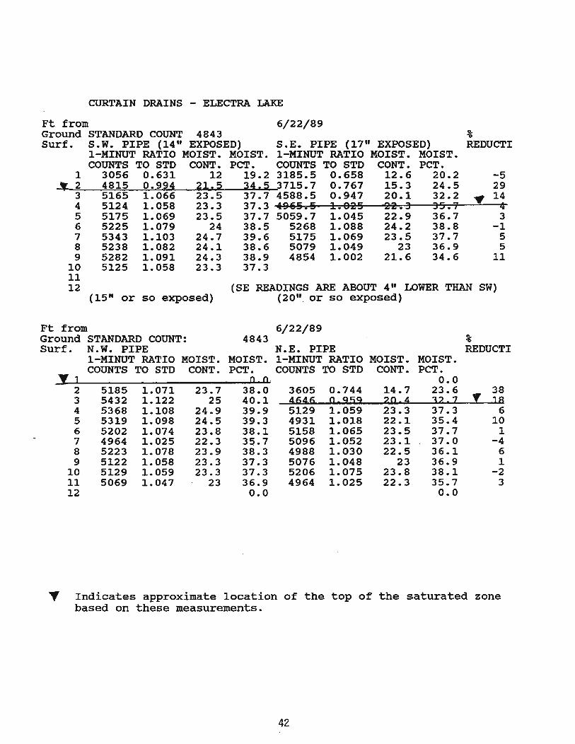
CURTAIN DRAINS - ELECTRA LAKE
Ft from 6/22/89 Ground STANDARD COUNT 4843 Surf. S.W. PIPE (14" EXPOSED) S.E. PIPE (17" EXPOSED)
I-MINOT RATIO MOIST. MOIST. I-MINOT RATIO MOIST. MOIST. COUNTS TO STD CONT. PCT. COUNTS TO STD CONT. PCT.
% REDUCTI
1 3056 0.631 12 19.2 3185.5 0.658 12.6 20.2 -5 ..... ~"'""-!2;=--~4~8~1;.;::5~..::i0~.-=::9-=::9~4_~2~l.:.o. 5~---,3"",,4~ ...... 5~3715. 7 0.767 15.3 24.5 29
3 5165 1.066 23.5 37.7 4588.5 0.947 20.1 32.2 " 14 4 5124 1.058 23.3 37.3 ~4~9~6~5~.~5~~1~.~9~2~5~~2~2~.~3~~3~5r..~7~~--~4 5 5175 1.069 23.5 37.7 5059.7 1.045 22.9 36.7 3 6 5225 1.079 24 38.5 5268 1.088 24.2 38.8 -1 7 5343 1.103 24.7 39.6 5175 1.069 23.5 37.7 5 8 5238 1.082 24.1 38.6 5079 1.049 23 36.9 5 9 5282 1.091 24.3 38.9 4854 1.002 21.6 34.6 11
10 5125 1.058 23.3 37.3 11 12
Ft from
(15" or so exposed)
Ground STANDARD COUNT: Surf. N.W. PIPE
I-MINOT RATIO MOIST. COUNTS TO STD CONT.
~] 2 5185 1.071 23.7 3 5432 1.122 25 4 5368 1.108 24.9 5 5319 1.098 24.5 6 5202 1.074 23.8 7 4964 1.025 22.3 8 5223 1.078 23.9 9 5122 1.058 23.3
10 5129 1.059 23.3 11 5069 1.047 23 12
(SE READINGS ARE ABOUT 4" LOWER THAN SW) (20". or so exposed)
6/22/89 4843 %
N.E. PIPE REDUCTI MOIST. I-MINOT RATIO MOIST. MOIST. PCT. COUNTS TO STD CONT. PCT.
o 0, 0.0 38.0 3605 0.744 14.7 23.6 • 38 40.1 ~6~6 o 959 20 4 32 2 ]8 39.9 5129 1.059 23.3 37.3 6 39.3 4931 1.018 22.1 35.4 10 38.1 5158 1.065 23.5 37.7 1 35.7 5096 1.052 23.1 '. 37.0 -4 38.3 4988 1.030 22.5 36.1 6 37.3 5076 1.048 23 36.9 1 37.3 5206 1.075 23.8 38.1 -2 36.9 4964 1.025 22.3 35.7 3 0.0 0.0
" Indicates approximate location of the top of the saturated zone based on these measurements.
42
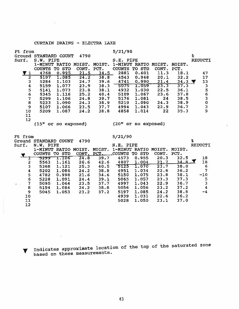
CURTAIN DRAINS - ELECTRA LAKE
Ft from 5/21/90 Ground STANDARD COUNT 4790 % Surf. S.W. PIPE S.E. PIPE REDUCTI
I-MINOT RATIO MOIST. MOIST. 1-MlNOT RATIO MOIST. MOIST. COUNTS TO STD CONT. PCT. COUNTS TO STD CONT. PCT.
!1 4768 0.995 21.5 34.5 2881 0.601 11.3 18.1 47 2 5197 1.085 24.2 38.8 4543 0.948 20.1 32.2 17 3 5284 1.103 24.7 39.6 4741 0.990 21.4 34.3 • 13 4 5159 1.077 23.9 38.3 -S075 1.059 23.3 37.3 3 5 5141 1.073 23.8 38.1 4932 1.030 22.5 36.1 5 6 5345 1.116 25.2 40.4 5109 1.067 23.6 37.8 6 7 5299 1.106 24.8 39.7 5176 1.081 24 38.5 3 8 5223 1.090 24.3 38.9 5219 1.090 24.3 38.9 0 9 5107 1.066 23.5 37.7 4994 1.043 22.9 36.7 3
10 5209 1.087 24.2 38.8 4858 1.014 22 35.3 9 11 12
(15" or so exposed) (20" or so exposed)
Ft from 5/21/90 Ground STANDARD COUNT 4790 % Surf. N.W. PIPE N.E. PIPE REDUCT I
1-MlNOT RATIO MOIST. MOIST. 1-MlNOT RATIO MOIST. MOIST.
'f COUNTS TO STD CONT. P~~. COUNTS TO STD CONT. PCT. 1 5299 1.106 24.8 39.7 4573 0.955 20.3 32.5 18 2 5563 1.161 26.6 42.6 4807 1.004 21:7 34 8 .. 18 3 5368 1.121 25.3 40.5 5125 1.070 23.7 38.0 6 4 5202 1.086 24.2 38.8 4951 1.034 22.6 36.2 7 5 4782 0.998 21.6 34.6 5150 1.075 23.8 38.1 -10 6 5228 1.091 24.4 39.1 5065 1.057 23.3 37.3 5 7 5095 1.064 23.5 37.7 4997 1.043 22.9 36.7 3 8 5194 1.084 24.2 38.8 5056 1.056 23.2 37.2 4 9 5045 1.053 23.2 37.2 5197 1.085 24.2 38.8 -4
10 4939 1.031 22.6 36.2 11 5028 1.050 23.1 37.0 12
T Indicates approximate location of the top of the saturated zone based on these measurements.
43
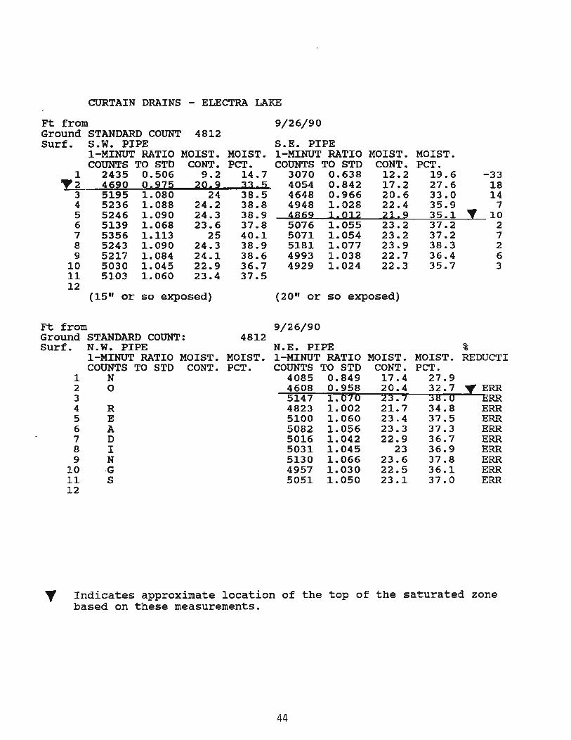
CURTAIN DRAINS - ELECTRA LAKE
Ft from 9/26/90 Ground STANDARD COUNT 4812 Surf. S.W. PIPE S.E. PIPE
1-MINUT RATIO MOIST. MOIST. 1-MlNUT RATIO MOIST. MOIST. COUNTS TO STD CONT. PCT. COUNTS TO STD CONT. peT.
1 2435 0.506 9.2 14.7 3070 0.638 12.2 19.6 -33 ~2 4690 OI~Z:2 2g.~ JJ. ~~ 4054 0.842 17.2 27.6 18
3 5195 1.080 24 38.5 4648 0.966 20.6 33.0 14 4 5236 1.088 24.2 38.8 4948 1.028 22.4 35.9 7 5 5246 1.090 24 .• 3 38.9 jS69 1.D12 2112 35·1 Y 10 6 5139 1.068 23.6 37.8 5076 1.055 23.2 37.2 2 7 5356 1.113 25 40.1 5071 1.054 23.2 37.2 7 8 5243 1.090 24.3 38.9 5181 1.077 23.9 38.3 2 9 5217 1.084 24.1 38.6 4993 1.038 22.7 36.4 6
10 5030 1.045 22.9 36.7 4929 1.024 22.3 35.7 3 11 5103 1.060 23.4 37.5 12
(15" or so exposed) (20·· or so exposed)
Ft from 9/26/90 Ground STANDARD COUNT: 4812 Surf. N.W. PIPE N.E. PIPE %
1-MlNUT RATIO MOIST. MOIST. 1-MINUT RATIO MOIST. MOIST. REDUCTI COUNTS TO STD CONT. PCT. COUNTS TO STD CONT. PCT.
1 N 4085 0.849 17.4 27.9 2 0 4608 0.958 20.4 32.7 ~ERR 3 5147 1.070 23.7 38.0 ERR 4 R 4823 1.002 21.7 34.8 ERR 5 E 5100 1.060 23.4 37.5 ERR 6 A 5082 1.056 23.3 37.3 ERR 7 D 5016 1.042 22.9 36.7 ERR 8 I 5031 1.045 23 36.9 ERR 9 N 5130 1.066 23.6 37.8 ERR
10 ·G 4957 1.030 22.5 36.1 ERR 11 S 5051 1.050 23.1 37.0 ERR 12
" Indicates approximate location of the top of the saturated zone based on these measurements.
44
APPENDIX E
STANDARD PLANS (M-STANDARD) AND SPECIFICATIONS APPLICABLE AT THE TIME OF THE PUBLICATION OF THIS FINAL REPORT
45
CROUNO LINE
12" MIN.
FILTER .... ItR ..... (O-ASS A)
[U8ANKVEttT .... TER .... SLOPES Ql!WN
PLASTIC DRAINAGE CORE PINNEO TO SIDE or TRENCH 6" PERfORAT£D
UNDERDRAIN PIPE OR THE SIZE SPEOFOED
ON THE PLANS-l.l.:.L!~ CEOltxnLE (DRAINAGE)"""':.:' I~~t~ CEOItXTILt (ORAINACE)
(BOTH SIDES or CORE)
GEOTEXnLE (ORAllOAC(l~I..s ..... (CLASsa I I , ... NIH
PIPE UNDER DRAIN
SHOULDER PAYEur.T , (HBP OR PCC) I ~ i~
AGGREGATE BASE I OR SU8GRADE i
I
rILJt:R MATERIAl (CLASS A)
GEOTEXTI(,£ (IIRAIN..:£) (ClASS 8) (OVERLAPPED ON TOP)
PIPE EDGE DRAIN
FRENCH DRAIN
--- RQAft'SIM GRADtNC
SHO(~'a~E OR Pee) .--L '.-:' ':< g::,,'Wf.., IlATER .... R PA\IE"ENT L-B--" ,
----'ll .... AGGREGATE BASE
OR SU8GRADE DRAINAGE CORE
GEOCOMPOSITE EDGE DRAIN
WAll
.::J-r ......
--.i
~
P[RI'ORATEO UNOERORAIII PIPE WRAPPED WITH CEOTEXTILE (DMlIIMlE)
GEOCOMPOSITE UNDERDRAIN
GEOT£XTll.E (ORAINAlXI '(80TH SIDES OF CORE
• • YI<. PERFORATED UNDERD.AI" PoPE .. RAPPED WITH GEDTEXTll.E (DAAlNAIX)
GEOCOMPOSITE DRAIN WITHOUT PIPE GEOCOMPOSITE
DRAIN WITH PIPE
REVISIONS "~~~I
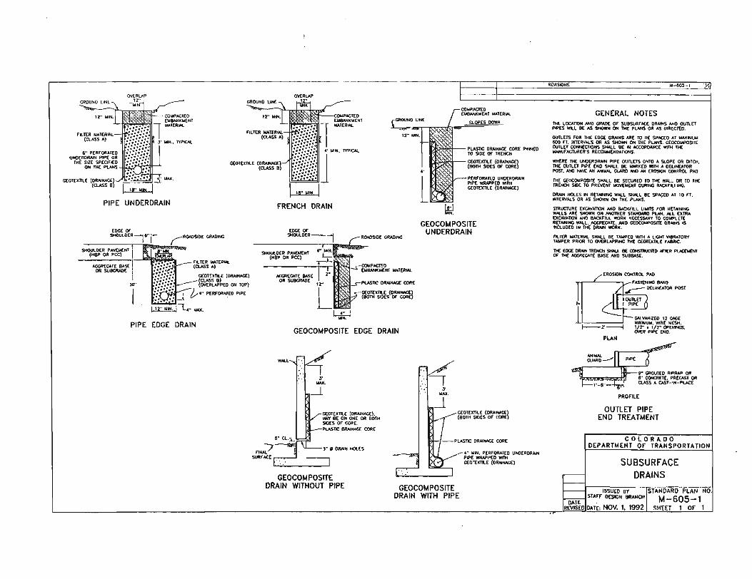
GENERAL NOTES THE LOCAnOH AND GRADE OF SUBSURFAC[ DRAINS AND OUTLET PIPES WILL BE AS SHOWN ON THE PlANS OR AS DIRECTED.
OUTLETS FOR THE EDCE DRAINS ARE TO 8E SPACED AT .... , .. U .. &DO n . JNT[RYAlS OR AS SHOWN ON THE PlANS. GEOCOMPOSIlE OUTlET CONNECTIONS SHAlL BE IN ACCORDANCE WITH THE """'UFIICTlIRER'S RECOIIIIENDATIONS.
WltERE THE UNDER DRAIN PIPE OUTlETS ONTO A SLOPE OR DITCH. THE OUTlET PIP[ END SHAlL 8E _xED WITH A DELINEATOR POST • ..,.., HoWE AN ......... Q.WIO AND AN EROSION CONTROl PAD.
THE CEOCOllPOSIT[ SMAlL BE SECURED TO THE "AlL OR TO THE TRENCH SIDE TO PREVENT IoIOVEUENT DURING IlACl<FlLLING.
DRAIN NOlES IN RETAINING WAlL SHAlL BE SPACEO AT 10 FT. INTERVAlS OR AS SHOVnt ON THE Pt.ANS. •
STRUCTURE [XCAVAlIOK AHO IlACl<flLl UIlITS FOR RETAINING ..... LS ARE SHOWN ON ANOTHER $TANDARO PlAN. AlL [XTRA EXCAYAl10II AND UCKFlll WORX NEc[SSAR'I TO COlll'LETE RETAINING WAlL. AGGREGATE. AND CEOCOUPOSITE DRAINS IS ..a.uoro IN THE DRAIN WORx.
',-.u .... TER .... SHAll BE T""'EO WITH A lIGHT Yl8RATOR't T .... PER PRIOR TO OVERLAPPING THE CEOTEXnLE FABRIC.
11<[ Eoc[ DRAIN TRENCH 5HOi.L BE CXlNSIlIIJCIt:D ArTER P\JC£>IENT or THE AGGREGATE lIAS[ AND SUBBASE.
PLAN
PRonLE
OUTLET PIPE END TREATMENT
........ 1
COLORADO DEPARTMENT or TRANSPORTATION
SUBSURFACE DRAINS
mum BY ISTAHOi.Ri)··PLANNo DATE STAFr DESIGN BRANCH 1'.1-605-1 EVISEDIDATE: NOV. 1. 1992 SHEET 1 OF 1
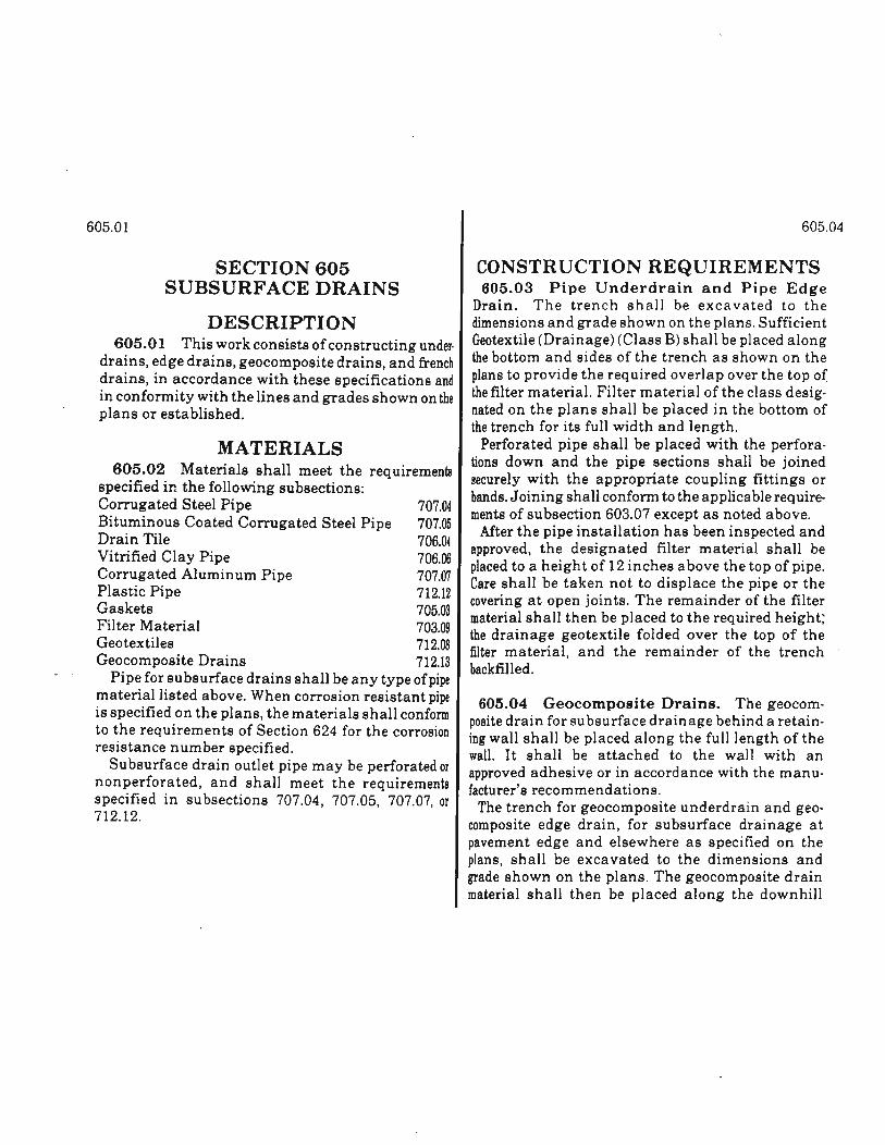
605.01
SECTION 605 SUBSURFACE DRAINS
DESCRIPTION 605.01 This work consists of constructing under·
drains, edge drains, geocomposite drains, and french drains, in accordance with these specifications and in conformity with the lines and grades shown on the plans or established.
MATERIALS 605.02 Materials shall meet the requirements
specified in the following subsections: Corrugated Steel Pipe 707.04 Bituminous Coated Corrugated Steel Pipe 707.05 Drain Tile 706.04 Vitrified Clay Pipe 706.06 Corrugated Aluminum Pipe 707.07 Plastic Pipe 712.12 Gaskets 705.03 Filter Material 703.09 Geotextiles 712.08 Geocomposite Drains 712.13
Pipe for subsurface drains shall be any type of pipe material listed above. When corrosion resistant pipe is specified on the plans, the materials shall conform to the requirements of Section 624 for the corrosion resistance number specified.
Subsurface drain outlet pipe may be perforated or nonperforated, and shall meet the requirements specified in subsections 707.04, 707.05, 707.07, or 712.12.
605.04
CONSTRUCTION REQUIREMENTS 605.03 Pipe Underdrain and Pipe Edge
Drain. The trench shall be excavated to the dimensions and grade shown on the plans. Sufficient Geotextile (Drainage) (Class B) shall be placed along the bottom and sides of the trench as shown on the plans to provide the required overlap over the top of the filter material. Filter material of the class designated on the plans shall be placed in the bottom of the trench for its full width and length.
Perforated pipe shall be placed with the perforations down and the pipe sections shall be joined securely with the appropriate coupling fittings or bands. Joining shall conform to the applicable requirements of subsection 603.07 except as noted above.
After the pipe installation has been inspected and approved, the designated filter material shall. be placed to a height of 12 inches above the top of plpe. Care shall be taken not to displace the pipe or the covering at open joints. The remainder of the filter material shall then be placed to the required height; the drainage geotextile folded over the top of the filter material, and the remainder of the trench backfilled.
605.04 Geocomposite Drains. The geocomposite drain for subsurface drainage behind a retaining wall shall be placed along the full length of the wall. It shall be attached to the wall with an approved adhesive or in accordance with the manufacturer's recommendations.
The trench for geocomposite underdrain and geocomposite edge drain, for subsurface drainage at pavement edge and elsewhere as specified on the plans, shall be excavated to the dimensions and grade shown on the plans. The geocomposite dra~n material shall then be placed along the downhlll
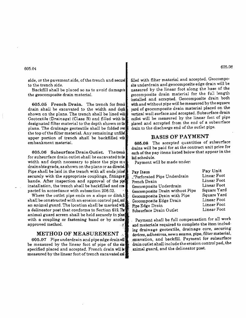
605.04
side, or the pavement side, ofthe trench and secured to the trench side.
Backfill shall be placed so as to avoid damageto the geocomposite drain material.
605.05 French Drain. The trench for french drain shall be excavated to the width and depth shown on the plans. The trench shall be lined wi~ Geotextile (Drainage) (Class B) and filled with the designated filter material to the depth shown on the plans. The drainage geotextile shall be folded over the top of the filter material. Any remaining untilled upper portion of trench shall be backfilled with embankment material.
605.06 Subsurface Drain Outlet. The trench for subsurface drain outlet shall be excavated toth! width and depth necessary to place the pipe on a drainable grade, as shown on the plans or as directed.
605.08
filled with filter material and accepted. Geocomposite underdrain and geocomposite edge drain will be measured by the linear foot along the base of the geocomposite drain material for the full length installed and accepted. Geocomposite drain both with and without pipe will be measured by the square yard of geocomposite drain material placed on t~e vertical wall surface and accepted. Subsurface dram outlet will be measured by the linear foot of pipe placed and accepted from the end of a subsurface drain to the discharge end of the outlet pipe.
BASIS OF PAYMENT , 605.08 The accepted quantities of subsurface drains will be paid for at the contract unit price for each of the pay items listed below that appear in the bid schedule.
Payment will be made under:
Pipe shall be laid in the trench with all ends joined Pay Item securely with the appropriate couplings, fittings~. -"Perforated Pipe Underdrain
Pay Unit Linear Foot Linear Foot Linear Foot Square Yard Square Yard Linear Foot Linear Foot Linear Foot
bands. After inspection and approval of the pi~' French Drain installation, the trench shall be backfilled and com. Geocomposite Underdrain pacted in accordance with subsection 206.03. Geocomposite Drain without Pipe
Where the outlet pipe ends on a slope or ditch,H" Geocomposite Drain with Pipe shall be constructed with an erosion control pad,and Geocomposite Edge Drain an animal guard. The location shall be marked with "l>i,pe Edge Drain a delineator post that conforms to Section 612. The Subsurface Drain Outlet animal guard screen shall be held securely in place ;~ with a coupling or fastening band or by another i Payment shall be full compensation for all work approved method. .;! and materials required to complete the item includ
METHOD OF MEASUREMENT,~ 605.07 Pipe underdrain and pipe edge drain wiD
be measured by the linear foot of pipe of the size specified placed and accepted. French drain will be measured by the linear foot of trench excavated and
ing drainage geotextile, drainage core, securing devices, adhesi ves, sewn seams, pipe, filter material, excavation and backfill. Payment for subsurface 'drain outlet shall include the erosion control pad, the
:. "animal guard, and the delineator post.
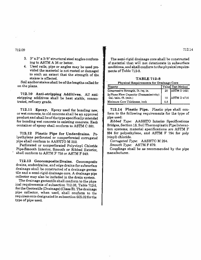
712.09
3. 3" x 3" x 3/8" structural steel angles conform. ing to ASTM A 36 or better.
4. Used rails, pipe or angles may be used provided the material is not rusted or damaged to such an extent that the strength of the. stakes is affected.
Soil anchor stakes shall be of the lengths called for on the plans.
712.10 Anti-stripping Additives. All anti. stripping additives shall be heat stable, concen. trated, refinery grade.
712.11 Epoxy. Epoxy used for bonding new, or wet concrete, to old concrete shall be an approved product and shall be of the type specifically intended for bonding wet concrete to existing concrete. Each container of epoxy shall conform to ASTM C 881.
712.12 Plastic Pipe for Underdrains. Po. lyethylene perforated ornonperforated corrugated pipe shall conform to AASHTO M 252.
Perforated or nonperforated Polyvinyl Chloride Pipe-Smooth Interior, Smooth or Ribbed Exterior
- shall conform to ASTM F 758 or ASTM F 949. '
712.13 Geocomposite Drains. Geocomposite drains, underdrains, and edge drains for subsurface drainage shall be constructed of a drainage geotex. tile and a semi· rigid drainage core. A drainage pipe collector may also be included in the drain system.
The drainage geotextile shall conform to the phys. ical requirements of subsection 712.08, Table 712.3, for the Geotextile (Drainage) (Class B). The drainage pipe collector, when used, shall conform to the req uirements designated in subsection 605.02 for the type of pipe used.
712.14
The semi·rigid drainage core shall be constructed of material that will not deteriorate in subsurface conditions, and shall conform to the physical requirements of Table 712·8.
TABLE 712-8 Physical Requirements for Drainage Core
Property Value Test Method Compressive Strength, lb.lsq. in. 20 ASTM D 1621 In·Plane Flow Capacity (Transmissivity) Gal.lmin.lft. (min.) 10 ASTM D 4716
Minimum Core Thickness, inch 0.5
712.14 Plastic Pipe. Plastic pipe shall con· form to the following requirements for the type of pipe used:
Ribbed Type: AASHTO Interim Specifications Bridges, Section 18, Soil Thermoplastic Pipe Interaction systems; material specifications are ASTM F 894 for polyethylene, and ASTM F 794 for poly (vinyl) chloride.
Corrugated Type: AASHTO M 294. Smooth Type: ASTM F 679. Couplings shall be as recommended by the pipe
man ufacturer.