Embed Size (px)
Citation preview
ENGINEERING INSTRUCTION
ATM C-DOT SYSTEM – AN INTRODUCTION
No. C-DOT/ATM/A-003
No of Pages. 36
Issue No. 01
Issued By: T&D, Circle
Approved By: CGM T&D Circle
Date of Issue 12-03-2005
Amendment No (If Any) NIL
No of Pages
Issued by:
Approved By:
Date of Issue
Restricted use by BSNL Employees only
All efforts have been made to incorporate all relevant up to date information available, anydiscrepancies or need for addition or deletion is felt necessarily may please be intimated to this officefor further improvement, on E-Mail Id [email protected].
BHARAT SANCHAR NIGAM LIMITED
(A Govt. of India Enterprise) TECHNICAL & DEVELOPMENT CIRCLE,
SANCHAR VIKAS BHAWAN, RESIDENCY ROAD, JABALPUR, MP-482001 1
ELECTORNIC SWITCHING
ENGINEERING INSTRUCTIONS C-DOT/ATM/A-003
BHARAT SANCHAR NIGAM LIMITED
A Govt of India Enterprises Restricted to Telecom Staff
Page 2 of 2
Issue-1 Date
ATM C-DOT SYSTEM – AN INTRODUCTION 1.0 SCOPE This EI describes the Introduction to the ATM Switching System developed and deployed by C-DOT. 2.0 GENERAL
ATM (Asynchronous Transfer Mode) is a transfer technique which has been adopted as the underlying transport and switching protocol for provision of Broadband-ISDN services to offer integrated broadband services to the customers. Working of ATM and Frame Relay is similar with the difference that the packet lengths are of Fixed size for ATM, while they are of variable size in the case of Frame Relay. The fixed size packets in ATM are known as Cells. The ATM transfer mode is termed asynchronous as it allows asynchronous operation between the SEND and RECIVE clocks while the difference between the clocks is removed by insertion or removal of empty cells. ATM provides transfer support for datas varying from low to very high bandwidth as well as services from Constant Bit Rate (CBR) to Variable Bit rate (VBR), ATM treats all the services in a similar manner which ensures a homogeneous network with the core function being simple transport and switching of cells, while all the service dependent functions are carried out only at the edges of the network. The basic function of the ATM switching system is to route the cells from the input port to the designated output port. The functions distributed in the ATM switching scenario are : (a) functions defined as in B-ISDN Protocol reference Model (b) relaying of the cells (c) support and implement traffic control functions as per ITU-T recommendation 1.371 3.0 MODULES: The three modules in the ATM Switching system are: The INPUT Modules (the entry point of traffic into the ATM switching system) at the switch port to receive the cells, the CELL SWITCH FABRIC (CSF) performs the routing and the OUTPUT Module prepares the cells for transmission. 3.1 INPUT MODULE
PHYSICAL LAYER ATM LAYER (extracts ATM cells from incoming SDH frames) (processing the cells & routing through CSF) - optical to electrical signal conversion - error checking in the cell header - digital bit stream extraction - traffic shaping - extracting ATM cell payload ATM cells - translation of VPI/VCI values - discarding empty cells - sorting signaling & management cells - deciding destination output port - adding routing tag
3.2 CELL SWITCH FABRIC (CSF)
Routing of Data, Signaling and Management cells between other functional blocks Buffering of cells Multiplexing and concentration of traffic Redundancy functions Broadcasting of cells Cell scheduling or fixing priority for cells on delay accruing Monitoring of congestion and activation of its indication
ELECTORNIC SWITCHING
ENGINEERING INSTRUCTIONS C-DOT/ATM/A-003
BHARAT SANCHAR NIGAM LIMITED
A Govt of India Enterprises Restricted to Telecom Staff
Page 3 of 3
Issue-1 Date
3.3 OUTPUT MODULE Receives cells from CSF and prepare them for physical transmission on the outgoing link Removal of internal routing tag attached to each cell from CSF Insertion of signaling/management cells received from CSF into outgoing cell stream New VPI/VCI values for multicast cells inserted from VP/VC database HEC (header error control) generated for ATM cell header as VPI/VCI values are changed Mapping of ATM cells into SDH frame Filling gaps with empty ATM cells Electrical to optical signal conversion
4.0 ATM SERVICES
A User can opt for ATM services in two ways: a) Permanent Virtual Circuit PVC b) Switched virtual Circuit SVC - manually configured - connection set up on demand - monthly fee & payment for the usage - similar to direct dialed telephone call of the circuit. No charge for non-use of - VP&VC used for connection circuit 4.1 Class of Services Offered
Class A services: voice telephony / video service. Circuit emulation service is provided for 2Mbps and 34Mbps trunk Class B services: compressed voice/video service Class C services: X.25/frame Relay service Class D services: Local area networking Constant Bit Rate (CBR): Class A service offered & peak bit rate guaranteed. Highest priority will be transferred first Variable Bit Rate (VBR): Real time VBR (rtVBR) & non rtVBR rtVBR: for Class B services & average bit rate guaranteed non rtVBR: for Class C/D services Available Bit Rate (ABR): minimum bit rate guaranteed, uses unused bandwidth Unspecified Bit Rate (UBR): uses unused bandwidth; cannot occupy bandwidth during peak times if no spare capacity is available.
4.2 SUPPORTED APPLICATION SERVICES
Data Applications : *LAN interconnection *Virtual private network *Leased line Voice Applications : * Virtual private network * Trunk service Video Applications : *Video Conferencing * Virtual Private Network * Multimedia application Supported Supplementary Services :
5.0 THE C-DOT ATM ARCHITECTURE For the deployment of ATM in the backbone the network element ATM-Cross connect (ATM-XC) is used. Also, some access units, which support the services and converts them into cells, can also be supported on ATM network. The two main constituents of the C-DOT ATM architecture are the ATM Core switch (CAX) & the ATM Multiplexer (CAM). The C-DOT ATM switch has a total throughput of 2.5 Gbps expandable to 40 Gbps. It supports ATM cell transfer over both SDH (STM-1) & PDH (E-3). The switch can be deployed as a cross connect, up gradable to provide complete switching function. Also, the same equipment is configurable to provide remote multiplexing or concentration function. The access function is loosely coupled to the switch and connected to the switch through standard interface. The switch architecture provides the flexibility for different configurations. It separates out the application specific functions from the core switching and transport function. As a result new applications may be introduced easily as the need arises. Different non-ATM & E1 ATM interfaces can be supported easily through the use of ATM Multiplexer. It may be noted that these additional interfaces can be supported directly in the Core Switch as well, for a smaller requirement.
The switch architecture supports distributed multi-processing environment, and provides scalable processing capacity, suitable for different applications. As standard interface is used for interconnecting different modules, the modules
ELECTORNIC SWITCHING
ENGINEERING INSTRUCTIONS C-DOT/ATM/A-003
BHARAT SANCHAR NIGAM LIMITED
A Govt of India Enterprises Restricted to Telecom Staff
Page 4 of 4
Issue-1 Date
can be easily removed from the core switch. The basic C-DOT ATM switch comprises both CAX & CAM. The ATM Switch provides high reliability and easy Expandability characteristics.
5.1 SYSTEM OVERVIEW
The C-DOT CAX is a 16 x 16 ATM switch belonging to the C-DOT BISDN family which provides easy solution to complex multiple networks problem. This 16 x 16 CAX is the first product in this group, which is used to support native cell relay service over ATM. Its architecture is similar to the switch. It converts non-ATM traffic into ATM cells. ATM cells from different interfaces are aggregated and passed onto the switch via standard physical interfaces The switch handles both ATM and non -ATM interfaces. Application specific non- - ATM interfaces are provided in a loosely coupled manner. The C-DOT CAM is also a 16 x 16 ATM switch terminating ATM interfaces on SDH & PDH. The core switch provides the basic cell switching function These ATM interfaces may be received from the Multiplexers or an ATM UNI (User network Interface) or NNI (Network Network interface). Interconnection between the core switches provide an ATM backbone for switching & transporting of different services. A number of Multiplexers may be connected to the core switch in a loosely coupled manner. 5.2 ATM SWITCH CONFIGURATION:
This switch can be configured in any of the following ways to support ATM. As an ATM crossconnect ( VPX / VCX ) As an ATM path switch ( VPS ) As an ATM local exchange ( LEX ) As an ATM tandem exchange ( TEX ) As an ATM remote unit ( RSU ) As an ATM multiplexer ( MUX) .
5.3 SERVICES supported by the ATM SWITCH This switch supports various kinds of services, which can be broadly classified as: Broadband & narrowband services. ATM Core & Edge switching. Internet service provision. Legacy networks integration ATM networks and services interworking.
5.4 EXTERNAL PHYSICAL INTERFACES SUPORTED BY THE SWITCH ATM UNI Interface:
• 155 Mbps STM-1 ATM interface • 34 Mbps E -3 interface
ATM NNI Interface: • 155 Mbps STM -1 ATM interface • 34 Mbps E -3 interface
5.5 SIGNALING The signalling virtual circuits and the virtual circuits carrying the user information shares the same physical medium. The signaling handles following types of connections
Point to point connection: This is a connection with only two end points which can be unidirectional or bi-directional symmetric or bi-directional asymmetric.
Point to multi-point connection: This is a unidirectional connection of associated ATM VC or VP links & associated nodes. The signaling has following call control capabilities
Having setup a call, it is possible to add more users within the same call by establishing one or more connection. Individual users are able to suspend connection without affecting other users in the same call. The user is able to re-negotiate the connection QOS parameter during the call. 5.5.1 UNI SIGNALING REQUIREMENT ATM User - Network Signaling:
ELECTORNIC SWITCHING
ENGINEERING INSTRUCTIONS C-DOT/ATM/A-003
BHARAT SANCHAR NIGAM LIMITED
A Govt of India Enterprises Restricted to Telecom Staff
Page 5 of 5
Issue-1 Date
At UNI the switch supports multiple VPs, supporting signaling VC, so that the customer may be connected to one or more local exchange.
Supports point to point signaling VCC for transport of signaling. ATM Network - Network Signaling:
Associated mode of signaling is supported. Only point to point signaling is supported (fixed VCI per VP).
6.0 Routing Plan: 6.1 Fixed path routing is supported. 1.Traffic and Congestion Control: 6.1.1 Traffic Control functions for ATM interface
Virtual path connection may be used in the network, where the individual VCCs are statistically multiplexed and the network does not have knowledge of QOS parameter of individual VCCs. VP connection is also used to separate traffic. The information contained in the traffic contract is accessible to CAC(Connection admission control) function. Resource is allocated based on the availability and demanded traffic contract. Usage parameter control
The UPC detects the non conforming cells on VPC or VCC basis & takes suitable actions, like, dropping the cell or tagging. The conforming cells are passed transparently.
6.1.2 Congestion control functions for ATM interface The congested node discards cells explicitly identified as belonging to non-compliant connection. Explicit forward congestion indication When congestion is detected at the node the cells are marked. 6.2 Network CLOCK Synchronization
Synchronized network clock is provided by an external network synchronization equipment over G.703 /10(120 ohm symmetrical) interface. 7.0 Software Architecture 7.1 The software architecture is broadly classified into two parts i.e. Services management and Network Resources management .It has following features:
Uses a Distributed Process Environment (DPE) for both services & resources management. (QoS) is an integrated part of service management Resources are dynamically assigned & configured to support flexibility of service support. Management is an integrated part of service provision. The architecture has three layers i.e. services, resources & DPE. 7.1.1 Service Management
Service management supports provisioning of services & their management by users & providers. It consists of Access & Subscription session and allows user to negotiate management requirements with service providers. Providers are able to deploy & withdraw services using service life cycle management. Upon receipt of a service request a new service group is initiated from service group template. Service type uniquely identifies the type of service while a service group is attached to the implementation of the service. The deployment manager deploys or withdraws a service from a virtual service repository. Service, service group, service group template are managed by deployment manager while service type is managed by service type manager. Service Factory is responsible for creation & deletion of each individual service instance of a specific service type. Service template is used for creation & deletion of a service instance. Each service instance is monitored & controlled (stop, resume, kill etc.) by service instance manager. The subscription management is handled by subscription manager. It maintains subscription contracts between user and provider. 7.1.2 Resources Management
ELECTORNIC SWITCHING
ENGINEERING INSTRUCTIONS C-DOT/ATM/A-003
BHARAT SANCHAR NIGAM LIMITED
A Govt of India Enterprises Restricted to Telecom Staff
Page 6 of 6
Issue-1 Date
This is similar to service management. Unlike service management, resource management is driven by provider's management policy. It provides management services to the service layer, which allows information, & communication services to setup connections, control their quality & specify management support.
7.2 Network Management Agent Functions: (FCAPS functionality)
FCAPS is Fault management, Configuration management, Accounting management, Performance management and Security management A network management agent is placed in the switch & it communicates with the switch and the network manager at the centralized network management center. 7.2.1 CONFIGURATION MANAGEMENT
This includes initializing & maintaining network as well as adding & updating the relationships among components & status management. It deploys resources for expected service demand as well as assigning services and features to end-users. 7.2.2 FAULT MANAGEMENT
This includes corrective action for fault recovery once the fault is detected or when near fault condition degrades the service provided. It also performs routine maintenance tests (diagnostics) on a scheduled basis and initiates tests to detect and correct problems before service trouble is reported. 7.2.3 PERFORMANCE MANAGEMENT
This evaluates the behavior and performance of network resources and also collects several service parameters to ensure the most efficient utilization of resources and their ability to support user service level objective. 7.2.4 ACCOUNTING MANAGEMENT
This processes & manipulates service & resource utilization records & generates customer-billing aspects. 7.2.5 SECURITY/PASSWORD MANAGEMENT
This protects & controls access to both network & network management system against intentional or accidental abuse, unauthorized access & communication loss.
8.0 HARDWARE ARCHITECTURE OF C-DOT ATM SWITCH 8.1 The Core Switch (cax)Architecture
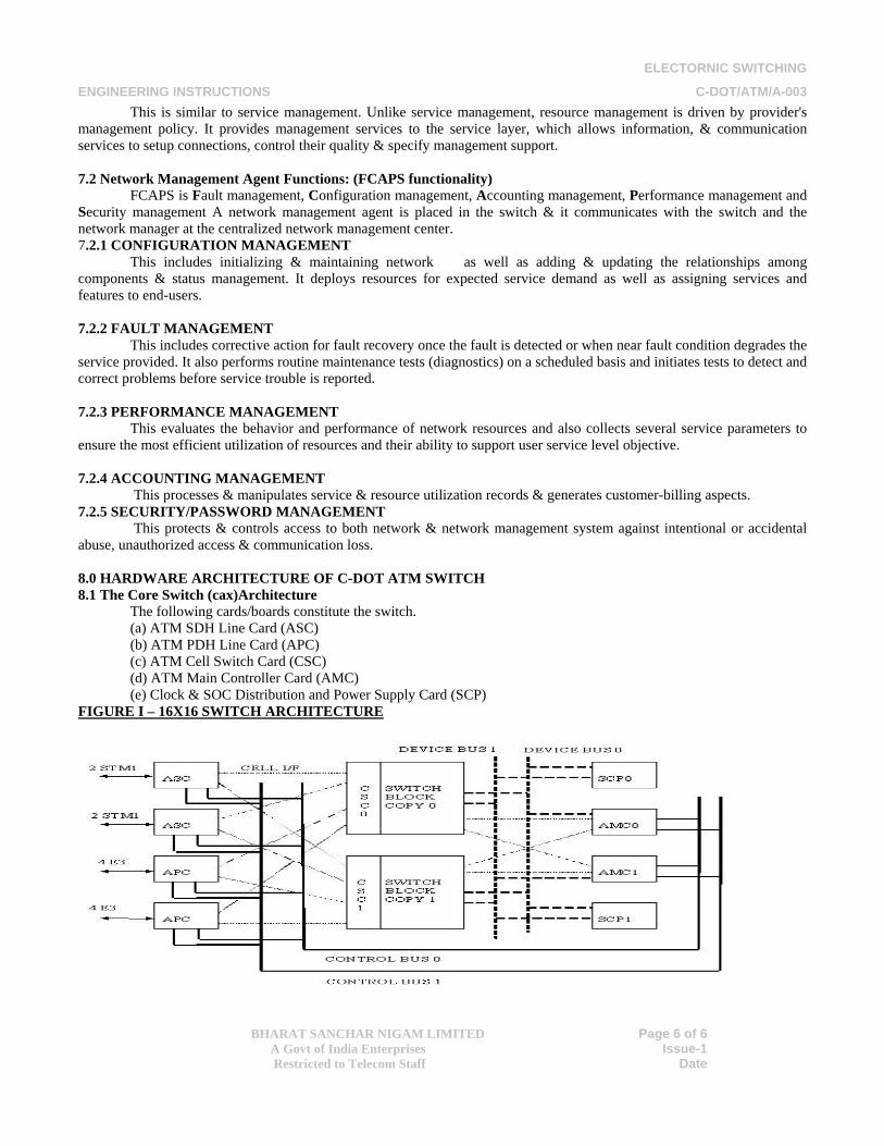
The following cards/boards constitute the switch. (a) ATM SDH Line Card (ASC) (b) ATM PDH Line Card (APC) (c) ATM Cell Switch Card (CSC) (d) ATM Main Controller Card (AMC) (e) Clock & SOC Distribution and Power Supply Card (SCP)
FIGURE I – 16X16 SWITCH ARCHITECTURE
ELECTORNIC SWITCHING
ENGINEERING INSTRUCTIONS C-DOT/ATM/A-003
BHARAT SANCHAR NIGAM LIMITED
A Govt of India Enterprises Restricted to Telecom Staff
Page 7 of 7
Issue-1 Date
Other interfaces can be supported by different line card types. The external links (STM-1/E3) terminate on the line cards (ASC/APC). The line cards extract the cells from the SDH/PDH payload, check the header of the received cells, attach the routing tag based on the received cell header, and pass the cells towards the cell switch card (CSC) via a cell interface. The cells get routed through CSC and come to the line card through the cell interface. In the line card the routing tags are removed and cells are mapped onto the payload of the SDH/PDH frame in the transmit direction. The line cards also translate the received cell header. The main controller card (AMC) handles the switch maintenance and other housekeeping functions. It communicates with the line cards through the 32 bit Control bus interface. The interface power for the cards is supplied by the SCP card. This card also distributes the clocks required for system operation. The main controller card controls the CSC and SCP cards using the Device Bus. (Figure 1).
8.1.1 ATM SDH Line Card (ASC)
• The ASC card performs the following functions:- • Terminates 2 STM-1 full duplex lines over optical fiber. • Provides the physical layer termination functions including framing/ defaming, cell delineation and cell rate
decoupling. • Supports 4K virtual connections per port. • Scans the active virtual connections and checks the adherence to accepted traffic contract. • Translates the address (VPI/VCI translation) and inserts the Routing Tag. • Provides the interface towards the switch fabric. The address translated cells are passed on to the fabric.. • Extracts the clock from the received link and retimes the data and passes on the extracted clock to the SCP card.
Sends out the data to external link with the network synchronized clock received from SCP. • Receives Clock and Start of Cell (SOC) from both copies of SCP, and selects the clock and SOC from the active
SCP. A/P~ signal is sent from both the copies of SCP to ASCs, to indicate the active/passive status of clock and SOC.
• Provides general house keeping activities and communicates with the AMC using the control bus. • Selects the active Control bus based on the Control bus select signal received from the active SCP. The Control bus
is synchronized with the clock received from the active SCP. • Indicates the health of the card to the SCP.
8.1.2 ATM PDH Line Card (APC) 8.1.3 ATM Cell Switch Card (CSC)
• This card is a 16x16 switch card. One of the ports is designated as the Control port and is used to connect the system cell interface received from the active AMC to the switch fabric. The other 15 ports are used to connect the user ports. The CSC card provides the following functions:-
• Receives clock and start of Cell from both copies of the SCP. Selects the clock and SOC from the active SCP. A/P~ line from the SCPs indicate the clock & SOC active/ Passive status.
• Provides cell switching function, both unicasting as well as multicasting. • In the receive direction CSC receives cells from active AMC, and switches it to the destination port. In the transmit
direction, the cells to the destination port are sent to both the copies of AMCs. • Receives 8 bit (data bus width ) device bus from both the copies of AMCs. CSC cards are not intelligent and act as
slave cards to AMC. 8.1.4 ATM Main Controller Card (AMC)
• The CSCs and SCPs act as slave to the active AMC. Both copies of CSC and SCP tune to the device bus from the active AMC. The AMC card performs the following functions:-
• Terminates the higher layer protocols for Network Management. • Keeps track of the individual units of the switch. • Monitors and analyses the statistics collected by all the functional blocks of the Switch. • Reconfigures the system, in case of any fault detected by the switch. • Receives the Clock and Start of Cell from SCPs for synchronous cell transport towards the copies of CSCs. It selects
the clock and SOC received from the active copy of SCP. The SCP A/P~ signal is hardwired, and received from both the copies of SCP.
ELECTORNIC SWITCHING
ENGINEERING INSTRUCTIONS C-DOT/ATM/A-003
BHARAT SANCHAR NIGAM LIMITED
A Govt of India Enterprises Restricted to Telecom Staff
Page 8 of 8
Issue-1 Date
• Selects the active Control bus based on the Control bus select signal received from the active SCP. The Control bus is synchronized with the clock received from the active SCP.
• Controls the SCPs and CSCs through the 8 bit wide device bus. Hardwired A/P~ signal from both the copies of AMCs are sent to the SCPs and CSCs, to indicate AMC A/P~ status.
• Communicates to the mate, the health and A/P~ status.
• 8.1.5 Switch Clock Distribution and Power Supply Card (SCP) • The SCP card is controlled by the active AMC through the device bus. The SCP card performs the following
functions: - • Distributes the 50 MHz clock and SOC24 (cell start signal every 24th cell interval) to both the AMC copies, both
copies of the CSC cards, and to all the line cards for synchronization. • ATM system cell interface between the CSCs and the other cards. The clock for synchronized operation of the
control bus interface is also derived in individual cards from the above mentioned signals. • It can receive the network synchronization clock (2.048 MHz on G.703/10, 120 ohms symmetric cable) from the
network synchronization equipment. It can also receive 16 kHz clock from two of the designated line cards for the external synchronization purpose. This arrangement ensures that the equipment can be configured as a remote unit parented to a main ATM exchange. Optionally it can generate internal clock. This card distributes 16 kHz synchronization signal to all the line cards so that the external interface are synchronized with respect to this clock.
• Generates 2.048MHz clock from the clock received from the designated line cards for the external synchronization purpose, and sends it to the Network Synchronization unit over G.703/10, 75 ohms coaxial cable.
• Distributes power to the interfaces in all the cards. The card separately distributes the 5V for TTL /CMOS and for PECL. The 5V TTL/CMOS and PECL supply from both the copies operate in load shared mode. This card sends the status of its own copy of AMC and forwards the status received from other cards (the line cards and the switch card) to the AMC.
• Indicates the card A/P~ status using hardwired signal to CSCs, Line cards (ASCs and APCs) and AMCs. This signal is used by the destination cards to select the active clock and SOC24 for the system cell interface and the active Control bus.
• Receives AMC A/P~ status signal from both the AMCs, and tunes the device bus to the active AMC
8.2 INTERCONNECTION & REDUNDANCY IN SWITCH 8.2.1 Cell Interface
The system cell interface connects the Line cards and AMCs to the CSCs for sending the cells for routing and receiving the routed cells from the CSC. For each STM-1 interface or for 4 E-3 interface there is a system cell interface between the line cards and the switch cards. Each system cell interface consists of, 4 signals carrying data and one signal in each direction. The system cell interface operates at 50 MHz. Each system cell interface is duplicated. In the receive direction (w.r.t. the switch) the line cards/AMCs copy the data and the signal towards both the copies of CSC. In the transmit direction (w.r.t. the switch), the line cards/AMCs receive the data and signal from both the CSCs and select one of them.
8.2.2 Control Bus
The Control bus is a 32 bit wide data bus for communicating between the line cards and the AMCs. There are two copies of control bus. The control bus operates in the Active/standby mode. The selection of the control bus in AMCs and the Line cards is based on the copy select signal received from Active copy of SCP. 8.2.3 Device Bus
The device bus is used for communicating between the AMC and the CSCs and SCPs. It consists of 16 bits of address and 8 bits of data. There are two device busses, one from each AMC. Both the copies of SCPs and CSCs are connected to each of the device bus. Both the copies of CSCs and SCPs are tuned to the device bus from active AMC. The Active/Passive status of the AMC is decided in the above mentioned cards based on the A/P~ signal received from both the copies of AMCs. If the signals indicate AMC active status for both the AMCs or AMC passive status for both the AMCs, the AMC active/passive status in the CSCs and SCPs remain unchanged. Figure 3.5 shows the device bus interface.
ELECTORNIC SWITCHING
ENGINEERING INSTRUCTIONS C-DOT/ATM/A-003
BHARAT SANCHAR NIGAM LIMITED
A Govt of India Enterprises Restricted to Telecom Staff
Page 9 of 9
Issue-1 Date
8.3 Clock Interface Both copies of SCP distribute the 50 MHz clock and SOC24 to all the line cards, CSCs and to the AMCs. The 50
MHz and the SOC24 are used for cell transfer over the cell interface. It is also used to derive the clock for the synchronous operation of the control bus. The 16 kHz clock is also distributed to the Line cards for network synchronization. The Line cards, CSCs, and the AMCs select the above set of signals from the active SCP. For this purpose, the SCPs distribute the A/P~ signal to the line cards, CSCs and the AMCs. If the signals indicate SCP active status for both the SCPs or SCP passive status for both the SCPs, the SCP active/passive status in the Line cards, CSCs and AMCs remain unchanged. The A/P~ status of the SCPs is programmed by the active AMC. Figure 3.6 shows the clock interface
. 8.3.1 AMC
The two copies of AMCs operate in the active/ standby mode. The two copies exchange A/P~ status and health status. Both the copies send A/P~ status to the CSCs and SCPs, to indicate which AMC, and hence, which device bus is active. If both the AMCs show the status active or passive the previous A/P~ status of AMCs are maintained. 8.3.2 CSC
The two copies of CSCs operate in the hot-standby mode. Both the cards receive same cells from the line cards and AMCs and route them.
8.3.3 SCP
Both copies of SCP distribute the 50 MHz clock, SOC24, network synchronization and control bus select signal to the AMCs, line cards and CSCs. The SCPs also distribute self A/P~ status to the above mentioned cards, based on which the clock and control bus selection is made in those cards. 8.4 ATM MULTIPLEXER ARCHITECTURE
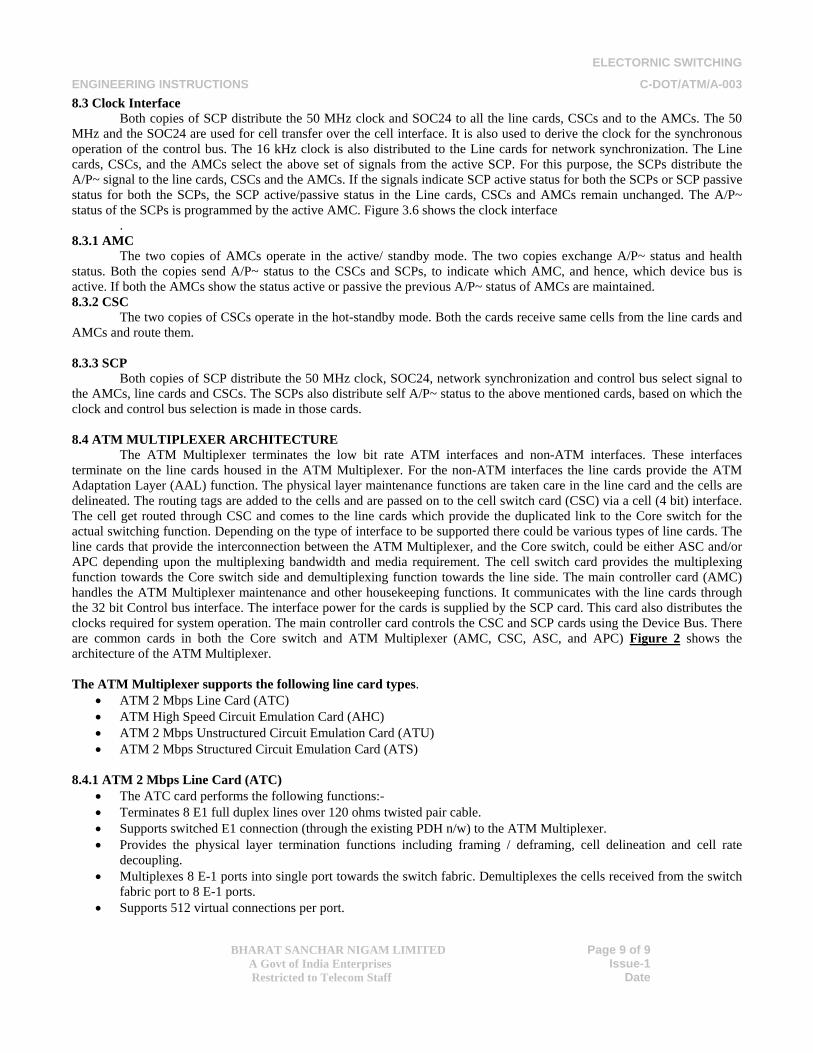
The ATM Multiplexer terminates the low bit rate ATM interfaces and non-ATM interfaces. These interfaces terminate on the line cards housed in the ATM Multiplexer. For the non-ATM interfaces the line cards provide the ATM Adaptation Layer (AAL) function. The physical layer maintenance functions are taken care in the line card and the cells are delineated. The routing tags are added to the cells and are passed on to the cell switch card (CSC) via a cell (4 bit) interface. The cell get routed through CSC and comes to the line cards which provide the duplicated link to the Core switch for the actual switching function. Depending on the type of interface to be supported there could be various types of line cards. The line cards that provide the interconnection between the ATM Multiplexer, and the Core switch, could be either ASC and/or APC depending upon the multiplexing bandwidth and media requirement. The cell switch card provides the multiplexing function towards the Core switch side and demultiplexing function towards the line side. The main controller card (AMC) handles the ATM Multiplexer maintenance and other housekeeping functions. It communicates with the line cards through the 32 bit Control bus interface. The interface power for the cards is supplied by the SCP card. This card also distributes the clocks required for system operation. The main controller card controls the CSC and SCP cards using the Device Bus. There are common cards in both the Core switch and ATM Multiplexer (AMC, CSC, ASC, and APC) Figure 2 shows the architecture of the ATM Multiplexer.
The ATM Multiplexer supports the following line card types.
• ATM 2 Mbps Line Card (ATC) • ATM High Speed Circuit Emulation Card (AHC) • ATM 2 Mbps Unstructured Circuit Emulation Card (ATU) • ATM 2 Mbps Structured Circuit Emulation Card (ATS)
8.4.1 ATM 2 Mbps Line Card (ATC)
• The ATC card performs the following functions:- • Terminates 8 E1 full duplex lines over 120 ohms twisted pair cable. • Supports switched E1 connection (through the existing PDH n/w) to the ATM Multiplexer. • Provides the physical layer termination functions including framing / deframing, cell delineation and cell rate
decoupling. • Multiplexes 8 E-1 ports into single port towards the switch fabric. Demultiplexes the cells received from the switch
fabric port to 8 E-1 ports. • Supports 512 virtual connections per port.
ELECTORNIC SWITCHING
ENGINEERING INSTRUCTIONS C-DOT/ATM/A-003
BHARAT SANCHAR NIGAM LIMITED
A Govt of India Enterprises Restricted to Telecom Staff
Page 10 of 10
Issue-1 Date
• Scans the active virtual connections. • Provides the interface towards the switch fabric. The address translated cells are passed on to the fabric through the
cell interface along with the signals from ATC to each copy of the switch block in each direction. • Sends out the data to external link with the network synchronized clock received from SCP. • Receives Clock and Start of Cell (SOC) from both copies of SCP and selects the clock and SOC from the active
SCP. A/P signal is sent from both the copies of SCP to ATCs, to indicate the active/passive status of clock and SOC. • Provides general house keeping activities and communicates with the AMC using the control bus. • Selects the active Control bus based on the Control bus select signal received from the active SCP. The Control bus
is synchronized with the clock received from the active SCP. • Indicates the health of the card to the SCP.
Figure 2 – ATM Multiplexer Architecture
8.4.2 ATM High Speed Circuit Emulation Card (AHC) The AHC card performs the following functions:-
• Terminates 3 E-3 lines over 75-ohm co-axial cables conforming to G.703. • Provides the physical layer termination functions for the E-3 links. • Converts the bits received over the E-3 link into cells as per AAL1 standard for the unstructured circuit emulation
and vice versa. • Multiplexes the cells generated from the 3 E-3 ports into single port towards the switch fabric. Demultiplexes the
cells received from the switch fabric port to the 3 E-3 ports.
ELECTORNIC SWITCHING
ENGINEERING INSTRUCTIONS C-DOT/ATM/A-003
BHARAT SANCHAR NIGAM LIMITED
A Govt of India Enterprises Restricted to Telecom Staff
Page 11 of 11
Issue-1 Date
• Support 3 virtual connections one for each E-3 port. • Translates the address (VPI/VCI translation) and inserts the Routing tag. • Provides the interface towards the switch fabric. The address-translated cells are passed on to the switch fabric
through a cell interface (for data) along with a signal. There would be 1 cell interface along with the 1 signal from AHC to each copy of the switch block in each direction.
• Extracts the clock from the received link and retimes the data. Optionally passes on the extracted clock to the SCP card.
• Sends out the data to external link with either the network synchronized clock received from SCP or loop clock or SRTS recovered clock. The transmit clock is selectable on per interface basis.
• Receives Clock and Start of Cell (SOC) from both copies of SCP and selects the clock and SOC from the active SCP. Hardwired A/P~ signal is sent from both the copies of SCP to AHCs, to indicate the active/passive status of clock and SOC.
• Provides general house keeping activities and communicates with the AMC using the control bus. • Selects the active Control bus based the Control bus select signal received from the active SCP. The Control bus is
synchronized with the clock received from the active SCP. • Indicates the health of the card to the SCP.
8.4.3 ATM 2 Mbps Unstructured Circuit Emulation Card (ATU) The ATU card performs the following functions:-
• Terminates 8 E-1 lines over 120ohm twisted pair as per G.703. • Provides the physical layer termination functions for the E-1 links. • Converts the bits received over the E-1 links into cells as per AAL1 standard for the unstructured circuit emulation
and vice versa. • Multiplexes the cells generated from the 8 E-1 ports into single port towards the switch fabric. Demultiplexes the
cells received from the switch fabric port to the 8 E-1 ports. • Supports 8 virtual connections one for each E-1 port. • Translates the address (VPI/VCI translation) and inserts the Routing tag. • Provides the interface towards the switch fabric. The address-translated cells are passed on to the switch fabric
through a cell interface (for data) along with a signal. There would be 1 cell interface along with the 1 signal from ATU to each copy of the switch block in each direction.
• Extracts the clock from the received link and retimes the data. Optionally passes on the extracted clock to the SCP card.
• Sends out the data to external link with either the network synchronized clock received from SCP or loop clock or SRTS recovered clock or adaptive clock. The transmit clock is selectable on per interface basis.
• Receives Clock and Start Of Cell (SOC) from both copies of SCP and selects the clock and SOC from the active SCP. Hardwired A/P~ signal is sent from both the copies of SCP to ATUs, to indicate the active/passive status of clock and SOC.
• Provides general house keeping activities and communicates with the AMC using the control bus. • Selects the active Control bus based the Control bus select signal received from the active SCP. The Control bus is
synchronized with the clock received from the active SCP. • Indicates the health of the card to the SCP. • 8.4.4 ATM 2 Mbps Structured Circuit Emulation Card (ATS) • The ATS card performs the following functions:- • Terminates 8 E-1 lines over 120 ohm twisted pair as per G.703. • Provides the physical layer termination functions for the E-1 links and supports framing and deframing of the
received bits as per G.704. • Supports channel associated signaling (CAS) and common channel signaling (CCS) which is selectable on per
interface basis. • Converts the bits received over the E-1 links into cells as per AAL1 standard for the structured circuit emulation and
vice versa. Supports n X 64Kbps circuit emulation with n any value from 1 to 32. 64Kbps channels from different links may be multiplexed into same virtual connection when supporting CCS.
• Supports transparent transfer of CAS signaling.
ELECTORNIC SWITCHING
ENGINEERING INSTRUCTIONS C-DOT/ATM/A-003
BHARAT SANCHAR NIGAM LIMITED
A Govt of India Enterprises Restricted to Telecom Staff
Page 12 of 12
Issue-1 Date
• Terminates CCS7 signaling channel in the card. • Multiplexes the cells generated from the 8 E-1 ports into single port towards the switch fabric. Demultiplexes the
cells received from the switch fabric port to the 8 E-1 ports. • Support a maximum of 256 (32X8) virtual connections. • Translates the address (VPI/VCI translation) and inserts the Routing tag. • Provides the interface towards the switch fabric. The address-translated cells are passed on to the switch fabric
through a cell interface (for data) along with a signal. There would be 1 cell interface along with the 1 signal from ATS to each copy of the switch block in each direction.
• Extracts the clock from the received link and retimes the data. Optionally passes on the extracted clock to the SCP card.
• Sends out the data to external link with either the network synchronized clock received from SCP or recovered from one of the pre-selected links.
• Receives Clock and Start of Cell (SOC) from both copies of SCP and selects the clock and SOC from the active SCP. Hardwired A/P~ signal is sent from both the copies of SCP to ATSs, to indicate the active/passive status of clock and SOC.
• Provides general house keeping activities and communicates with the AMC using the control bus. • Selects the active Control bus based the Control bus select signal received from the active SCP. The Control bus is
synchronized with the clock received from the active SCP. • Indicates the health of the card to the SCP.
8.5 Configuration 8.5.1 Core Switch configuration (CAX) The following configurations are possible for the 16X16 Switch.
• STM-1 ports - max 15, with 8 ASC cards in the slots marked for line cards. The 16th port in the switch is used by the two AMCs. In this scenario, one STM-1 port (out of 2) for one of the ASC cards (out of 8) will remain unequipped.
• E-3 ports - max 28, with 7 APC cards in the slots marked for the line cards. In this case out of 16 ports of CSC, 7 are used by the APC cards and one port is used by the two copies of AMC. The rest of the ports of the switch card remain unused.
• Any other intermediate combination of STM-1 and E-3 ports is also possible. • 8.5.2 ATM Multiplexer Configuration (CAM) • The following configurations are possible for the ATM Multiplexer. • ATM E1 ports - max 48, with 6 ATC cards in the slots marked for line cards (8 ports per card and 6 cards in the
system). The remaining 2 line cards are used for interface to switch (E3/STM-1). • E3 Circuit Emulation ports - max 15, with 5 AHC cards in the slots marked for line cards (3 ports per card and 5
cards in the system). • E1 Unstructured Circuit Emulation ports - max 48, with 6 ATU cards in the slots marked for line cards (8 ports per
card and 6 cards in the system). • E1 Structured Circuit Emulation ports - max 48, with 6 ATS cards in the slots marked for line cards (8 ports per card
and 6 cards in the system). • Any other intermediate combination of the ports is also possible.
8.6 Circuit Cards
This is the smallest system unit. All the circuit cards are of same dimension [415 mm (height) X 285 mm (depth) X 2.4 mm (thickness)]. The circuit boards are populated with surface mount devices, with double side mounting. The connectors are mounted with polarizer to ensure that the cards do not go into wrong slots on the back plane. All the cards are mounted with a faceplate. Cabling from the line cards to the FDF and DDF terminate on the faceplate and brought inside the card. On the two extremes of the faceplate are two plastic ejectors, which engage at the lip of the card frame. The ejectors provide the mechanical advantage during the jack-in or the jack-out of the card. A stiffener, made of aluminum, sitting on three sides of the card makes sure that the card does not bend. On the fourth side of the card the stiffening action is provided by the faceplate. All the processor based cards of the system (APC/ASC/BRI/SRI) have two push button switches, two LEDs (one green and the other red) and one D type connector mounted on the face plate. The top push button switch provides the card push-button
ELECTORNIC SWITCHING
ENGINEERING INSTRUCTIONS C-DOT/ATM/A-003
BHARAT SANCHAR NIGAM LIMITED
A Govt of India Enterprises Restricted to Telecom Staff
Page 13 of 13
Issue-1 Date
reset. The bottom push button switch is used for providing the control to the monitor for the debugging purpose. Both the push button switches have a protection to avoid accidental pressing of the above mentioned switches. The top green LED, when glowing, indicates that the card is receiving -48V supply. The bottom red LED, when glowing, indicates that the card health is bad, or, the card is not active. The D type connector is flushed with the faceplate, and is used for connecting the emulator during debugging. During the normal operation this connector remains unused. In the CSC card there is one push button switch and one green LED on the faceplate. The push button switch resets the card. The green LED indicates the presence of -48V power in the card. There is a push button switch and three LEDs (one green and two red) mounted on the SCP faceplate. The push button switch resets the card. The top green LED indicates the presence of -48V supply, the middle red LED glows to indicate interface power supply failure and the bottom red LED glows to indicate that -48V supply has gone below the threshold level. 8.7 Card Frame
The Card Frame houses the Circuit boards. The card frame dimension is 419 mm (Height) X 554 mm (Width) X 295 mm (Depth). The card frame has the guided rails both at the top and bottom side of the frame so that the circuit boards can slide into the respective slot positions. A total of 16 slot positions are provided in the card frame. Polarization is provided on the male connector to ensure that daughter cards do not go into the wrong slot.
There are two sets of power connectors at the top right hand and the top left hand corner of the back plane. The -48V power distribution is through the back plane only. There is an auxiliary power connector at the bottom left half corner of the back plane as seen from the rear side. This connector provides 5V to fan failure detection block .Also on the back plane, at both left hand and right hand center, are two auxiliary hard metric connectors. These connector are provided for combining the ACIA signals from the intelligent cards of each half of the back plane, and bring them to the ACIA patch cord. Hooter alarm and fan failure signals also are given from these connectors. There are two Device Bus Termination (DBT) cards sitting on the rear side of the back plane at the SCP0 and SCP1 slot positions. The DBTs provide the device bus termination for both the copies. There are also two Control Bus Termination (CBT) cards sitting on the rear side of the back plane at the two extreme line card slot positions. The CBTs provide the control bus termination for both the copies. Cabling is provided between SCP0 and all other cards, and, SCP1 and all other cards for equipment clock and Start of cell distribution. Twinax cables and the Start of Cell indication using co-axial cables distribute the clocks. There are also two loop back twinax cables for clock in SCP0 and SCP1
. 8.8 Cabinet
The cabinet houses one card frame. The Card frame is fixed to the cabinet via side plates sitting on the card frame, and vertical bars fixed to the cabinet. The card frame sits at the middle of the cabinet. The cabinet extends beyond the rear side of the card frame. At the top and bottom of the cabinet separate baffle structures are provided for the purpose of forced air-cooling. The bottom baffle structure has six fans mounted vertically. The fans suck the air in. The air flows between the slots in the card frame, and exits through the top baffle. The faceplates on individual cards ensure there is no air leakage. If some card slots are free, dummy faceplates should be put in those slots to maintain the air column. Air filter is put at the entry of the bottom baffle, to filter out dust particles.
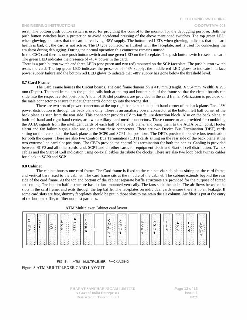
ATM Multiplexer Cabinet card layout
Figure 3 ATM MULTIPLEXER CARD LAYOUT
ELECTORNIC SWITCHING
ENGINEERING INSTRUCTIONS C-DOT/ATM/A-003
BHARAT SANCHAR NIGAM LIMITED
A Govt of India Enterprises Restricted to Telecom Staff
Page 14 of 14
Issue-1 Date
9.0 The Node Management equipment consists of the following :-
• Personal Computers 2 • Printers 2 • VT 100 Terminals 2 • Indicator panel for fire detection 1
10.0 Power Supply
The equipment requires -48V DC for its operation. The supply is derived from the commercial AC supply by using float rectifier - charger arrangement. A parallel battery back up is provided for uninterrupted operation of the equipment in the event of commercial AC supply failure. -48V DC and -48V ground are lead to the system cabinet, where it lands on the two power connectors in the backplane. Individual circuit cards tap the -48V supply from the backplane. Each card contains a fuse and filter module. There is an over-voltage and under-voltage detection and protection circuit in each card. The on-board power supply units (PSU) derive the necessary DC voltages like 5V, 3.3V and 2.5V as per the requirements of individual cards. The interface power to the cards is supplied from duplicated central source (SCP card). 11.0 Fiber Distribution Frame (FDF) & Digital Distribution Frame (DDF)
The Fiber Distribution Frame (FDF) and Digital Distribution Frame (DDF) are required for terminating the optical and electrical cables on the ATM switches and ATM MUX. Both subscriber and network cables can terminate on FDF/DDF. The cables from the FDF and the DDF are to be terminated at the ATM Switch, or at ATM MUX. Routing of these cables should be through a conduit. 12.0 Network Management System (NMS) 12.1 Introduction
The network manager supports an integrated management facility for a network of switches provisioned for ATM network. Initially the switch will support SNMP agent for the management of ATM networks. Finally the network management interface will migrate to Q3 interface. The management system contains several nodes each with a processing entity, termed an agent, and at least one management station and the management protocol used to convey management information between the agents & managed stations. Management stations monitors & controls managed elements via access to their management information. Management information is collection of managed objects residing in a virtual information store, termed the Managed Information Base (MIB). The network element view is used to control individual ATM network elements. 12.2 Network Management Layer (NML):
The NML manages all the NEs. It contains those functions used to manage an end to end telecommunications network. NML accesses to the network is provided by EML (Element Management Layer). The NML controls & coordinates the provision or modification of network resource capabilities in support of services to the customer through interactions with higher layer functions. It also provides higher layers with information such as the performance, availability & usage data.
12.3 Element Management Layer (EML):
The EML manages each network element on an individual basis & supports an abstraction of the functions provided by the Element Layer. 12.4 MAIN Functions Following functions are provided by the network element (NE) which are known as FCAPS functionality.
(a) Fault management (b) Configuration management (c) Accounting management (d) Performance management (e) Security management
12.4.1 Fault Management
ELECTORNIC SWITCHING
ENGINEERING INSTRUCTIONS C-DOT/ATM/A-003
BHARAT SANCHAR NIGAM LIMITED
A Govt of India Enterprises Restricted to Telecom Staff
Page 15 of 15
Issue-1 Date
Fault management is the - detection, localization and correction of abnormal behavior of the telecommunication network and it's environment. This involves the following:
• Notifying the network management system of a detected failure. • Logging failure reports • Isolating faults • Fault management is related to the following areas: • within service management • within network resource management • within management of DPE
12.4.2 Configuration Management Configuration Management (CM) Functional Requirements:
The configuration management involves the following functions: • ATM NE Configuration Identification & Change Reporting. • Configuration of UNIs, Inter NNI, Intra NNI & PNNI. • Configuration of ATM VP/VC Link Termination Points & Cross Connections. • Configuration of ATM VPC & VCC Termination Points. • Configuration of VPC & VCC OAM Segment End-points. • Event Flow Control.
. 12.4.2.1 Configuration Of UNIs and PNNIs:
(a) This provides command interface to support requests to configure physical path terminations on an ATM NE as either a User Network Interface (UNI) or PNNI. The following information are provided with each configuration request: Interface ID
• ID of underlying Physical path termination • Maximum number of simultaneously active VPCs supported • Maximum number of simultaneously active VCCs supported • Number of allocated VPI bits. • Number of allocated VCI bits • ATM subscriber address • Preferred carrier • ILMI channel identifier (b) It also supports management requests to retrieve configuration data associated with each UNI, inter NNI or intra NNI
terminating on the ATM NE. It further supports management requests to reconfigure the data elements. 12.4.2 .2 Configuration of VPL/VCL Termination Points & Cross Connections
Fig shows that • A physical path once terminated may be channelized into one or more VPLs. • A VPC once terminated may be channelized into one or more VCLs. • VPCs are composed of one or more cross-connected VPLs. • VCCs are composed of one or more cross-connected VCLs.
12.4.2 .3 Configuration of VPC & VCC OAM segment end points
This supports command interface functions to configure VPL or VCL termination points as either a segment or non-segment end point. Following command interfaces are supported
(a) This command interface supports management system requests to configure & reconfigure active VPL & VCL termination points as either segment or non segment end points.
(b) It also supports management system requests to retrieve the data stored in ATM NE that identifies whether a particular VPL or VCL termination point has or has not been configured as a segment end point. Event Flow Control
This supports suppression of ATM NE generated notifications based on one or more of the following:
ELECTORNIC SWITCHING
ENGINEERING INSTRUCTIONS C-DOT/ATM/A-003
BHARAT SANCHAR NIGAM LIMITED
A Govt of India Enterprises Restricted to Telecom Staff
Page 16 of 16
Issue-1 Date
(1) Notification type (2) Specific details of a notification type (3) Type of managed entity reporting the notification or (4) specific detail about the managed entity reporting the
notification. 12.4.3 Accounting Management 12.4.3.1 Charging related parameters
Some of the parameters that effect charging are specified at subscription time as a part of the service contract; these are the parameters that are relatively stable and apply to all the sessions of a particular service. There are others that are applied before a service session. The parameters related to charging may be classified as being a part of following components
: Access component - parameters related to subscription form the part of this component. The only parameter that is lying in this category is - Type of access. This includes variables such as number of links, capacity of lines, duration of subscription, the flat charge (if applicable), the redundancy, billing context (visible/invisible) and associated fault tolerance. utilization component - Utilization charges are in accordance with the service requested by the service subscriber. These charges are determined on the basis of the network resources and any additional functions required to provide the service to service subscriber. The values of the parameters under this component category are specified for both the directions of the connections. A call can be composed of potentially many connections. This component include two kinds of parameters on which charging are based. fixed - This component represents utilization of the resources like call set up - The connection subscribed to may support the capability for establishing the connection types taken from the following set, { PVC (occasional/periodic), SVC (occasional/periodic), Reserved ,point-to-point, point-to-multipoint } ; The subscriber will be charged a fixed amount in accordance with the number and type of service connection type ( from the given set) that he wishes to subscribe. This is a flat periodic charge, based on particular tariff parameters; the sub- scriber may or may not utilize all the communication types at his disposal. Call characteristics - This component represents the utilization of switching and transmission resources. The parameters included in this category are as such: called party - The called party parameter is used as an indication of the distance metrics involved in the communication. The charge levied is taken as function of the distance abstraction. Duration of the call - This information is derived from the signaling data as far as SVC is concerned and from the traffic contract in case of PVC (both permanent and reserved). The information regarding the duration of the call for SVC will be passed up by the CSM to SSM, after the communication session is over. Time based charging - The charging is based upon the time at which the call is made. E.g. reduction in the call rates by a factor in the late/early hours of the day. A database keeping the information giving the time-dividing factor is maintained. Priority - The priority parameter takes into account the number of high priority cells (CLP=1), originated at the user's end over a period of time. The information is forwarded by the CSM to SSM on a periodic basis. Again a table is maintained in order to translate the number of priority cells received per time quantum to appropriate charge amount. Traffic contract parameters - The traffic contract includes ATM traffic capability, QoS class and source traffic descriptor, Peak cell rate of the OAM F5 user cell flow and associated cell delay variation tolerance. These parameters are forwarded by the subscriber at the session setup time and are received as a part of signalling information. A table containing information for translation of this information into charging information is maintained.
ELECTORNIC SWITCHING
ENGINEERING INSTRUCTIONS C-DOT/ATM/A-003
BHARAT SANCHAR NIGAM LIMITED
A Govt of India Enterprises Restricted to Telecom Staff
Page 17 of 17
Issue-1 Date
Violation of the traffic Contract Parameters - This parameter is enforced when there is a policy of imposing penalty on the subscriber whose traffic is violating the agreed upon traffic contract. A penalty factor expressing charge/no of cells tagged per unit time is maintained. This information is forwarded by the CSM to the SSM on periodic basis . Volume used - The volume of cells flowing in from a particular user. 12.4.3.2 Accounting process:
• Following steps are involved in accounting: • Transport level traffic (usage information) is measured and collected. • Performance and traffic are measured. • Accounting events are passed either on-line or off-line. • The resource layer relays to upper layers the accounting information in terms of ATM specific metrics i.e. a
structure containing information such as Ingress total cells, ingress high priority cell and so on. • Accounting events are sent periodically and are turned into billing information, which is stored. Bill can be
generated for user according to the billing policy (weekly, monthly etc.). - This billing information is stored into the persistent storage. This information may be retrieved by the user application in due course. The overall bill will be forwarded to the subscriber under whose domain the user lies at the end of a specific period agreed upon in the service contract. This responsibility is entrusted to the subscriber module that has knowledge about the user and his related subscriber. The subscription module has the responsibility of maintaining all the service contracts for a particular subscriber
. 12.4.3.3 Functional Requirements
Accounting Management activity involves creation of following components. (a) Active Objects : • UA (User Agent) • USM, (Usage service session) • SSM (Service Session manager) and • CSM (b) Persistent Objects : • MgmtCtxt • Tariff Structure • Billing database
12.4.3.3.1 Named UA (User agent corresponding to a known user)
This is a rep representative of user in provider domain. It offers two accounting related interfaces. This is service independent and there will be as many instances of this object as the number of users. The named user agent has the responsibility of maintaining the billing records of all the users involved in service sessions.
Interfaces offered by named UA
This offers two accounting management related interfaces. The first interface provides operations that allow its clients to store billing data in the named UA. This data may later be retrieved by some other client to generate a bill for user . The second interface provides operations that allow its clients to retrieve billing information, from the named UA, corresponding to a time interval or to a particular user session. 12.4.3.3.2 USM (Usage Service Session)
This object is service specific and is created when a user wants to participate in a service session. For a service session corresponding to a service type, one USM is created. This object keeps various context information of a user. This object is deleted when the user leaves the service session. This object represents usage information of service type for a particular user, during a service session. USM is also responsible for one user's share of accumulated session related charges. USM interacts with the user's UA to store or manage billing records for that user. This offers two accounting related
ELECTORNIC SWITCHING
ENGINEERING INSTRUCTIONS C-DOT/ATM/A-003
BHARAT SANCHAR NIGAM LIMITED
A Govt of India Enterprises Restricted to Telecom Staff
Page 18 of 18
Issue-1 Date
interfaces. The first interface controls the delivery of USM generated accounting events, which are pushed to an accounting interface on UA by the USM as a consequence of session activity. The second interface offers operations to receive accounting events. The third interface keeps context information for service management, which are negotiated between user and the service provider.
12.4.3.3.3 SSM (Service Session Manager)
This manages information related to service specific and generic service session control. It has the responsibility of receiving the accounting records from the underlying CSM and relaying it further to USM's for conversion into billing event records. Interfaces offered by SSM
SSM offers two accounting related interfaces. • The first interface allows management of the accounting event reporting that is pushed to an accounting interface by
the SSM as a consequence of session activity. • The second interface offers operations to receive accounting events from CSM.
12.4.3.3.4 MgmtCtxt (Management Context)
This object keeps information of management contexts negotiated between user and the provider. This object will keep management contexts related to all the service management areas. Since different mgmtCtxts are possible, which are negotiated between different users and provider, therefore this object is a collection object.
12.4.3.3.5 Tariff
This object contains information about pricing information which provider will be charging to the user upon completion of the service transaction. The only interface offers operation to get tariff pricing information corresponding to specific QoS schema.
12.4.3.3.6 Billing Data base
This database object contains billing information corresponding to each user. Therefore there are multiple instances of Billing information object.
12.4.3.4 Functional activities Supported
Following functionalities are supported in accounting management: (a) Display subscriber accounting & billing information (b) Taking backup of billing data (c) Printing billing and accounting data
12.4.4 Performance management:
This supports functionality to gather statistical data for the purpose of monitoring and correcting the behavior and effectiveness of the network, network element or equipment and to aid in planning and analysis. Following functions are supported:
(a) Performance monitoring (b) Traffic management (c) UPC/NPC Disagreement monitoring (d) Performance management control (e) Network data collection (f) Physical Layer Protocol Monitoring • The command interface supports monitoring SDH transport performance. • The command interface also supports monitoring E3 transport performance. (g) ATM Cell Level Protocol Monitoring Cell level protocol monitoring involves collecting and threshold data counts that measure an ATM NE's ability to
successfully process and deliver incoming ATM cells. It checks protocol abnormality detected at the transmission convergence sub-layer and ATM layer. Logging is done at ATM NE for future retrieval & diagnostics. Separate counters are maintained for each count and each ATM interface.
(h) UPC/NPC Disagreement Monitoring
ELECTORNIC SWITCHING
ENGINEERING INSTRUCTIONS C-DOT/ATM/A-003
BHARAT SANCHAR NIGAM LIMITED
A Govt of India Enterprises Restricted to Telecom Staff
Page 19 of 19
Issue-1 Date
This monitoring is important for the network operator to distinguish between cells discarded due to user violating pre negotiated traffic descriptors and due to transmission errors & malfunctions. Following interfaces are supported for this purpose.
(1) The command interface supports initiating UPC/NPC disagreement monitoring on a limited number of VP/VC links at any point in time.
(2) The command interface also supports withdrawing UPC/NPC disagreement monitoring for a previous activated VP/VC link.
(3) It also supports retrieval of following counts from each monitored link. discarded cells (both CLP=0 & 1) discarded cells(only CLP=0) successfully passed cells successfully passed CLP=0 cells.
13.0 Detailed Software Architecture
This chapter gives detailed Software Architecture. Architecture can be decomposed into following subsystems: (a) Subscription and Accounting (b) Signaling (c) Fault Management (d) Configuration Management (e) Performance Management (f) Accounting and Billing
13.1 Subscription & Accounting
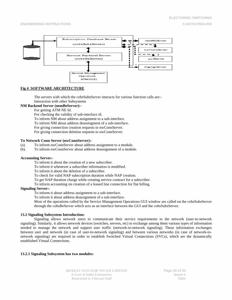
Subscription Server (or the cobsSubsServer ) is the database server, runs on the NMS connected to the ATM switch and is responsible for storing ATM services subscription related information in the database.
ATM service subscription information includes all the information needed to provide ATM services to a Subscriber, These are following:-
Subscriber information, i.e., the subscriber Name, contact address, telephone number, and also the billing information (billing cycle).
When a subscriber subscribes for ATM services, he/she has to be given a Network Access Point (NAP) for giving him/her access to the services. This NAP information for the subscriber is also created and kept in the database by the subscription server.
The information of the Service Contract with the subscriber is also managed and kept in the database by the subscription server.
Finally, the connection information for Subscriber is kept in the database by cobsSubsServer and during connection creation and deletion, the trigger is given accordingly to the switch entities by the subscription server. Besides the above mentioned functionalities, the cobsSubsServer is responsible for address assignment and deassignment to the various modules and sub-interfaces, which are used in NAP creation of a subscriber. Also, the System Parameters and Billing Parameters are managed (stored and modified) in the database by the subscription server. The complete Subscription Server architecture is shown below in figure 1. The interaction of cobsSubsServer with different servers is shown with bold dashed lines
ELECTORNIC SWITCHING
ENGINEERING INSTRUCTIONS C-DOT/ATM/A-003
BHARAT SANCHAR NIGAM LIMITED
A Govt of India Enterprises Restricted to Telecom Staff
Page 20 of 20
Issue-1 Date
Fig 4 SOFTWARE ARCHITECTURE
The servers with which the cobsSubsServer interacts for various function calls are:- Interaction with other Subsystems NM Backend Server (nemBeServer):-
For getting ATM NE Id. For checking the validity of sub-interface id. To inform NM about address assignment to a sub-interface. To inform NM about address deassingment of a sub-interface. For giving connection creation requests to nwConnServer. For giving connection deletion requests to nwConnServer.
To Network Conn Server (nwConnServer):- (a). To inform nwConnServer about address assignment to a module. (b). To inform nwConnServer about address deassignment of a module. Accounting Server:-
To inform it about the creation of a new subscriber. To inform it whenever a subscriber information is modified. To inform it about the deletion of a subscriber. To check for valid NAP subscription duration while NAP creation. To get NAP duration charge while creating service contract for a subscriber. To inform accounting on creation of a leased line connection for flat billing.
Signaling Server:- To inform it about address assignment to a sub-interface. To inform it about address deassignment of a sub-interface. Most of the operations called by the Service Management Operations GUI window are called on the cobsSubsServer through the cobsBeServer which acts as an interface between the GUI and the cobsSubsServer.
13.2 Signaling Subsystem Introduction:
Signaling allows network users to communicate their service requirements to the network (user-to-network signaling). Similarly, it allows network devices (switches, servers, etc) to exchange among them various types of information needed to manage the network and support user traffic (network-to-network signaling). These information exchanges between user and network (in case of user-to-network signaling) and between various networks (in case of network-to-network signaling) are required in order to establish Switched Virtual Connections (SVCs), which are the dynamically established Virtual Connections. 13.2.1 Signaling Subsystem has two modules:
ELECTORNIC SWITCHING
ENGINEERING INSTRUCTIONS C-DOT/ATM/A-003
BHARAT SANCHAR NIGAM LIMITED
A Govt of India Enterprises Restricted to Telecom Staff
Page 21 of 21
Issue-1 Date
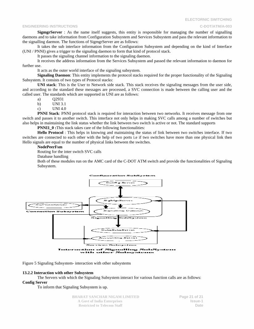
SigmgrServer : As the name itself suggests, this entity is responsible for managing the number of signalling daemons and to take information from Configuration Subsystem and Services Subsystem and pass the relevant information to the signalling daemon. The functions of SigmgrServer are as follows:
It takes the sub interface information from the Configuration Subsystem and depending on the kind of Interface (UNI / PNNI) gives a trigger to the signaling daemon to form that kind of protocol stack.
It passes the signaling channel information to the signaling daemon. It receives the address information from the Services Subsystem and passed the relevant information to daemon for
further use. It acts as the outer world interface of the signaling subsystem. Signaling Daemon: This entity implements the protocol stacks required for the proper functionality of the Signaling
Subsystem. It consists of two types of Protocol stacks: UNI stack: This is the User to Network side stack. This stack receives the signaling messages from the user side,
and according to the standard these messages are processed, a SVC connection is made between the calling user and the called user. The standards which are supported in UNI are as follows:
a) Q2931 b) UNI 3.1 c) UNI 4.0 PNNI Stack: PNNI protocol stack is required for interaction between two networks. It receives message from one
switch and passes it to another switch. This interface not only helps in making SVC calls among a number of switches but also helps in maintaining the link status whether the link between two switch is active or not. The standard supports
PNNI1_0 :This stack takes care of the following functionalities: Hello Protocol : This helps in knowing and maintaining the status of link between two switches interface. If two
switches are connected to each other with the help of two ports i.e if two switches have more than one physical link then Hello signals are equal to the number of physical links between the switches.
NodePeerFsm Routing for the inter switch SVC calls Database handling Both of these modules run on the AMC card of the C-DOT ATM switch and provide the functionalities of Signaling Subsystem.
Figure 5 Signaling Subsystem- interaction with other subsystems 13.2.2 Interaction with other Subsystem
The Servers with which the Signaling Subsystem interact for various function calls are as follows: Config Server
To inform that Signaling Subsystem is up.
ELECTORNIC SWITCHING
ENGINEERING INSTRUCTIONS C-DOT/ATM/A-003
BHARAT SANCHAR NIGAM LIMITED
A Govt of India Enterprises Restricted to Telecom Staff
Page 22 of 22
Issue-1 Date
For getting ATM NE Id and Module Id. To get the information about the equipage of a SVC interface. To get the various parameters for the equipped SVC interface and information about the defined signaling channel for that SVC interface. To get the information about De-Equipage of a SVC interface.
CobsSubsServer
To get the module address. To get the information about the addresses assigned to a sub-interface. To get the information about the de-assignment of addresses for a sub-interface. To verify that whether the subscriber is authorized to get the requested kind of services or not.
Accounting Server To inform the services subsystem to start the billing cycle for a particular subscriber for a particular kind of services. To inform the services subsystem to stop the billing cycle for a particular subscriber for a particular kind of services.
SwConnServer To reserve the ingress and egress VPI/VCI and the required bandwidth for the SVC connection and get a connection identifier. To inform the connection subsystem that call establishment process succeeds and the reserved VPI/VCI and bandwidth is now ready to be used Initially at the time of releasing the connection, deactivate the data path (means no data flow is allowed at a particular connection. When the SVC call is properly released then free the corresponding VPI/VCI and the bandwidth so that it can be reused for some other connections.
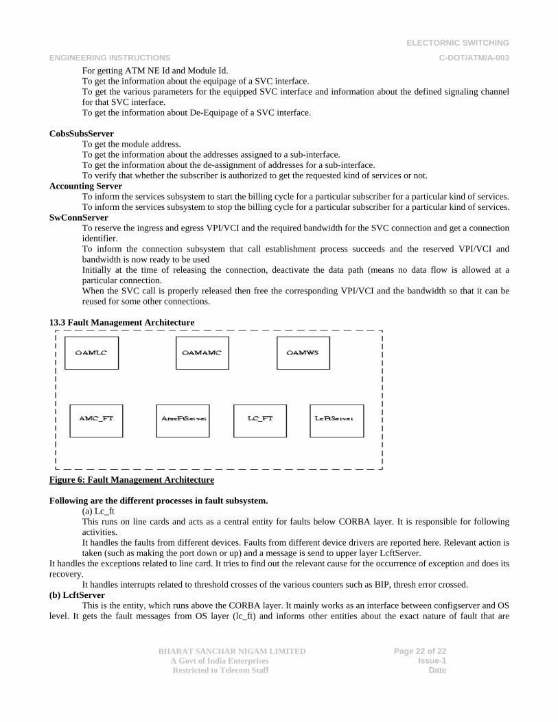
13.3 Fault Management Architecture
Figure 6: Fault Management Architecture Following are the different processes in fault subsystem.
(a) Lc_ft This runs on line cards and acts as a central entity for faults below CORBA layer. It is responsible for following activities. It handles the faults from different devices. Faults from different device drivers are reported here. Relevant action is taken (such as making the port down or up) and a message is send to upper layer LcftServer.
It handles the exceptions related to line card. It tries to find out the relevant cause for the occurrence of exception and does its recovery.
It handles interrupts related to threshold crosses of the various counters such as BIP, thresh error crossed. (b) LcftServer
This is the entity, which runs above the CORBA layer. It mainly works as an interface between configserver and OS level. It gets the fault messages from OS layer (lc_ft) and informs other entities about the exact nature of fault that are
ELECTORNIC SWITCHING
ENGINEERING INSTRUCTIONS C-DOT/ATM/A-003
BHARAT SANCHAR NIGAM LIMITED
A Govt of India Enterprises Restricted to Telecom Staff
Page 23 of 23
Issue-1 Date
reported to GUI and their log is kept in log files. GUI command to get or change the status of clock/unit/card reaches to the lc_ft via config and lcFtServer. (c) Amc_ft
This process runs on AMC cards and acts as a central entity for faults below CORBA layer. It is responsible for following activities.
It handles the faults from devices. Different drivers report their faults to this entity. Relevant actions are taken (such as making the port down or up) here and a message is send to upper layer AmcftServer. It is responsible for handling all switchovers (AMC, CSC, SCP). Clock selection and recovery in case of clock failure occurs.
It also takes care of power supply faults. All the SCP related faults are handled in AMC fault handler. All the faults are reported to AmcFtserver where relevant actions are taken and message is propagated to the front end and displayed at GUI.
It monitors the health status of all the cards. (d) AmcFtServer
This is the entity which runs above the CORBA layer on AMC card. It mainly works as an interface between configserver and OS level. It gets the fault message from OS layer (amc_ft) and informs other entities (running on front end or GUI) about the exact nature of fault that are reported to GUI and their log is kept in log files. Switchovers:
SCP switchover: Switch over can be done in two ways 1. From GUI: When a command is given from GUI for SCP switchover it checks the status of other SCP and if it
(stand by SCP) is in hot stand-by mode then it reinitializes the registers of new SCP and brings it up otherwise switchover can not be performed.
2. By rebooting/jacking out or when healthy card becomes faulty: When we jack out or reboot the working SCP, status of other SCP is checked and if it (stand by SCP) is hot stand-by mode then reinitializes the registers of new SCP and brings it up. If other SCP is in cold stand by mode then whole system will hang because there is no power supply to other cards.
CSC switchover: Switch over can be done in two ways 1. From GUI: When a command is given by operator from GUI for CSC switchover it checks the status of other
CSC and if it (stand by CSC) is hot stand-by mode then it reinitializes the registers of new CSC and make it up otherwise switchover can not be performed.
2. By rebooting/jacking out or when healthy card become faulty: On jacking out or reboot, the working CSC, status of other SCP is checked and if it (stand by CSC) is hot stand-by mode then it reinitializes the registers of new CSC and brings it up. If other CSC is in cold stand by mode then whole system will hang.
AMC switch over: This can be performed in 2 ways 1. By GUI: When a command is given by operator from GUI for AMC switchover it checks the status of other AMC
and if it (stand by AMC) is in hot stand-by mode then it reinitializes the registers of new AMC, download different servers and brings it up otherwise switchover can not be performed.
2 By rebooting/jacking-out or when healthy card becomes faulty: When we jack out or reboot the working AMC, status of other AMC is checked and if it (stand by AMC) is hot stand-by mode then it reinitializes the registers of new AMC, download different servers and brings it up. If other AMC is in cold stand by mode then whole system will hang.
Operation Administration and Maintenance (OAM) It describes the network management operations for ATM, generally known as operations, administration, and
maintenance (OAM). OAM mechanism is provided to detect defects and failures affecting the transport of user information by continuous/periodic checking. The basic OAM functionality is divided and taken care by following processes in C-Dot ATM switch.
• OAMLC • OAMWS • OAMAMC
OAMLC:
It is responsible for handling the various ATM layer faults (AIS, RDI, LOC) on the ATM connections. This server runs on ATM Line Cards (ASC, APC, ATC) only. This also provides an interface towards GUI/operator (through Backend) for initiating commands on ATM connections (Continuity Check and LoopBack). It provides the following functionality:
ELECTORNIC SWITCHING
ENGINEERING INSTRUCTIONS C-DOT/ATM/A-003
BHARAT SANCHAR NIGAM LIMITED
A Govt of India Enterprises Restricted to Telecom Staff
Page 24 of 24
Issue-1 Date
1) Handling the real time ATM layer Faults. 2) Provides interface to check the connectivity of the ATM connection on-demand (i.e. through LoopBack) as well
as continuously checking (through Continuity Check). 3) Asking device driver to generate the OAM cells in handling of faults (both on self and cross connected), as well
as Operator initiated command. OAMAMC: This server runs on the AMC and does the following:
1) Handles the case if any sub-interface or port goes down/up i.e. deciding for the action to be taken and generating different OAM cells as per the case.
2) It maintains the dynamic database for the status of all the channels of the all Line Cards. i.e. action taken on the side of fault as well as on the cross connected end, status of Continuity Check (enabled or not). OAMWS:
This server runs on the NMS and maintains the persistent database which is the same as on the AMC but persistent i.e. if the switch goes down status of all the channels on each card is maintained. It does only the file operations for storing and retrieving the status of any particular channel or all the channels for a or all the line card(s). 13.4 Configuration Management
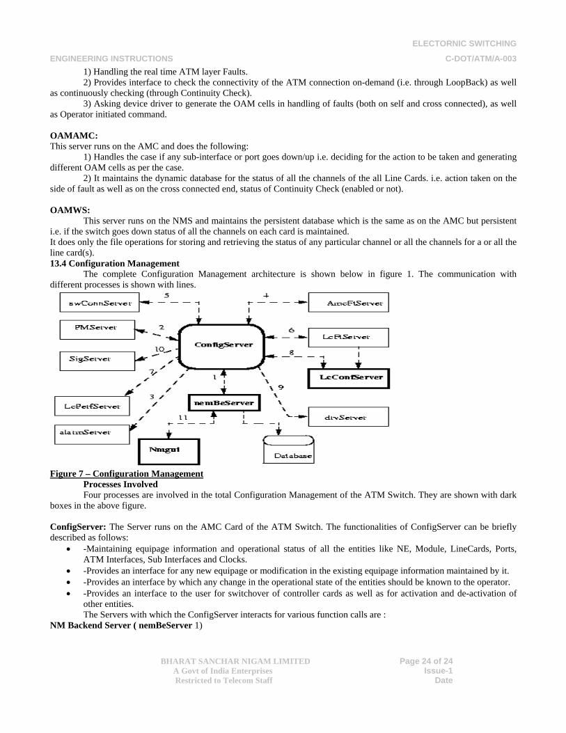
The complete Configuration Management architecture is shown below in figure 1. The communication with different processes is shown with lines.
Figure 7 – Configuration Management Processes Involved
Four processes are involved in the total Configuration Management of the ATM Switch. They are shown with dark boxes in the above figure. ConfigServer: The Server runs on the AMC Card of the ATM Switch. The functionalities of ConfigServer can be briefly described as follows:
• -Maintaining equipage information and operational status of all the entities like NE, Module, LineCards, Ports, ATM Interfaces, Sub Interfaces and Clocks.
• -Provides an interface for any new equipage or modification in the existing equipage information maintained by it. • -Provides an interface by which any change in the operational state of the entities should be known to the operator. • -Provides an interface to the user for switchover of controller cards as well as for activation and de-activation of
other entities. The Servers with which the ConfigServer interacts for various function calls are : NM Backend Server ( nemBeServer 1)
ELECTORNIC SWITCHING
ENGINEERING INSTRUCTIONS C-DOT/ATM/A-003
BHARAT SANCHAR NIGAM LIMITED
A Govt of India Enterprises Restricted to Telecom Staff
Page 25 of 25
Issue-1 Date
• -For getting persistent information about all the entities ( NE, Module, LineCards, Ports, AtmInterfaces, SubInterfaces , Clocks )
• -For persisting information about the above entities whenever any new configuration is done. • -nemBeServer acts as an interface between the Network Management Operations GUI window and ConfigServer. • Performance Backend Server (PMServer2). • -For informing about the equipage of entities like Ports and SubInterfaces. • Alarm Backend Server ( alarmServer3 ) • -For raising or clearing any alarms on the entities.
AMC Fault Server ( AmcFtServer4 )
• -For getting the operational status of all the LineCards (mandatory as well as optional) and Control Bus. • -For Setting the Clocks. • -For Switching over the controller cards whenever one copy of the card goes faulty or the operator wants a switch
over. • AMC Connection Server (swConnServer5) • -For informing about the equipage of entities like NE, Module, ATM Interfaces and Sub Interfaces. • -For informing about the status change of entities like AtmInterfaces and SubInterfaces. • LineCard Fault Server ( LcFtServer6 ) • -For getting the operational Status of ports. • -Any state change of ports is informed by LcFtServer to LcConfServer
LineCard Performance Server ( LcPerfServer7)
• -For informing about the equipage and status change of entities like Ports and SubInterfaces. LineCard Configuration Server (LcConfServer8)
• -For getting the type of the card actually jacked in the system. • -Any change in the status of ports is informed by LcConfServer to ConfigServer when triggered by LcFtServer.
LineCard Driver Server (drvServer9)
• -For programming any devices in the LineCard if needed. Signaling Server (SigServer 10)
• -For informing the equipage information of the SubInterfaces. nemBeServer:
This Server runs on the workstation. It is responsible to persist the configuration data in the database. It has the direct interface with the Database. It acts as the interface between the Network Management GUI window and the ConfigServer. The Servers with which the nemBeServer interacts are :
• Configuration Server (ConfigServer 1) • -For communicating any operator commands to ConfigServer when initiated by the operator. • -For persisting any configuration information to the database. • Network Management Window (nmgui 11) • -It receives commands from nmgui and communicates to ConfigServer. Sends any reports to nmgui.
LcConfServer : This Server runs on the LineCards of the ATM Switch. It maintains the H/W type of the card jacked in the System.
It informs to the ConfigServer of any change in the status of ports. The Servers with which LcConfServer interacts are :
• Configuration Server (ConfigServer ) -For informing ConfigServer any change in the status of the ports.
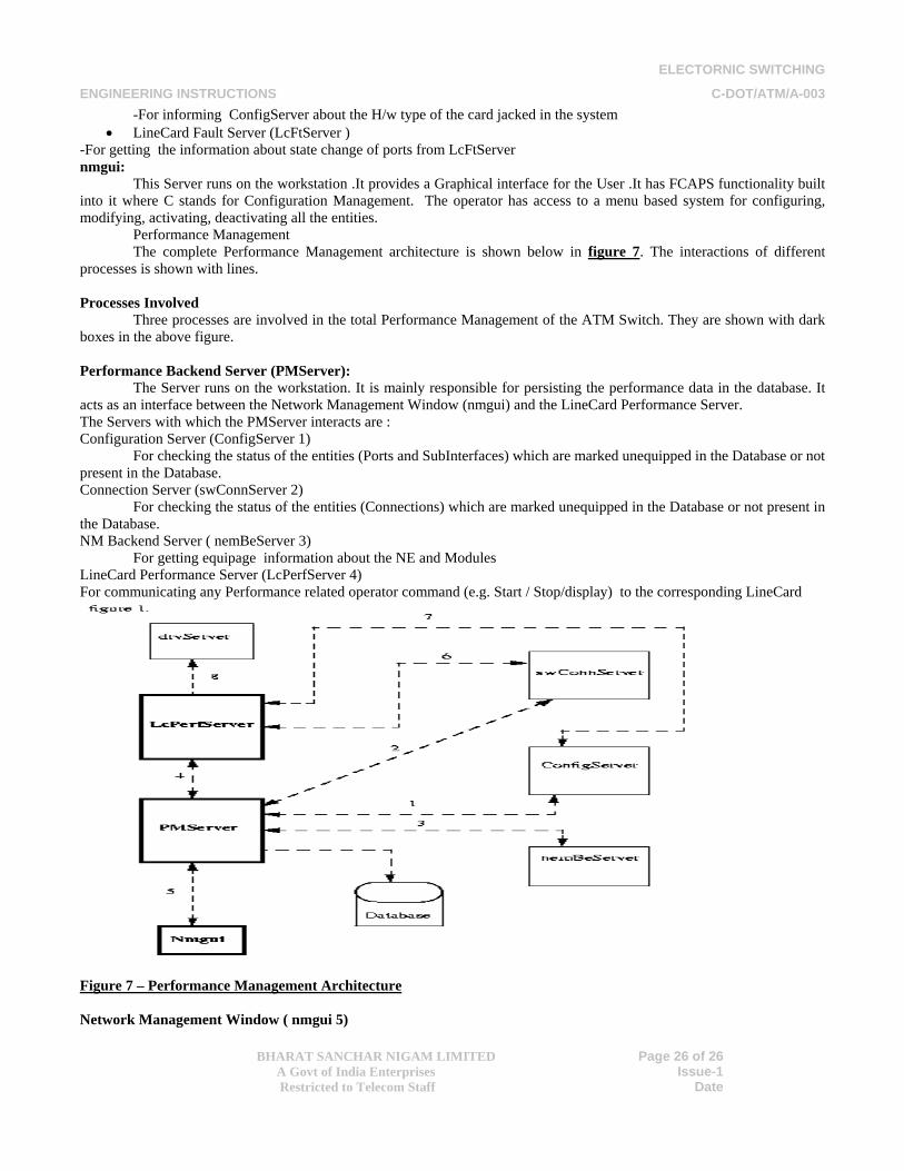
ELECTORNIC SWITCHING
ENGINEERING INSTRUCTIONS C-DOT/ATM/A-003
BHARAT SANCHAR NIGAM LIMITED
A Govt of India Enterprises Restricted to Telecom Staff
Page 26 of 26
Issue-1 Date
-For informing ConfigServer about the H/w type of the card jacked in the system • LineCard Fault Server (LcFtServer )
-For getting the information about state change of ports from LcFtServer nmgui:
This Server runs on the workstation .It provides a Graphical interface for the User .It has FCAPS functionality built into it where C stands for Configuration Management. The operator has access to a menu based system for configuring, modifying, activating, deactivating all the entities. Performance Management The complete Performance Management architecture is shown below in figure 7. The interactions of different processes is shown with lines. Processes Involved
Three processes are involved in the total Performance Management of the ATM Switch. They are shown with dark boxes in the above figure.
Performance Backend Server (PMServer):
The Server runs on the workstation. It is mainly responsible for persisting the performance data in the database. It acts as an interface between the Network Management Window (nmgui) and the LineCard Performance Server. The Servers with which the PMServer interacts are : Configuration Server (ConfigServer 1)
For checking the status of the entities (Ports and SubInterfaces) which are marked unequipped in the Database or not present in the Database. Connection Server (swConnServer 2)
For checking the status of the entities (Connections) which are marked unequipped in the Database or not present in the Database. NM Backend Server ( nemBeServer 3)
For getting equipage information about the NE and Modules LineCard Performance Server (LcPerfServer 4) For communicating any Performance related operator command (e.g. Start / Stop/display) to the corresponding LineCard
Figure 7 – Performance Management Architecture Network Management Window ( nmgui 5)
ELECTORNIC SWITCHING
ENGINEERING INSTRUCTIONS C-DOT/ATM/A-003
BHARAT SANCHAR NIGAM LIMITED
A Govt of India Enterprises Restricted to Telecom Staff
Page 27 of 27
Issue-1 Date
-It receives commands from nmgui and communicates to the LcPerfServer of the corresponding LineCard. Sends the performance reports to nmgui. Line Card Performance Server (LcPerfServer):
The Server runs on each LineCard of the ATM Switch. It is mainly responsible for getting the performance counters from different devices of the Card. It sends the counters to PMServer for persistence to the database. The Servers with which the LcPerfServer interacts are :
• Performance Backend Server (PMServer 4 ) -For receiving performance related operator commands. -For getting the details of the entities (ports, vpcs , vccs ) where PM is to be started during initialization. -For checking the existence of the specified entities (ports, vpcs , vccs) and for inserting new PM entities . -For sending the counters of those entities (related to the card), where performance is being monitored after every 15 minutes.
• Configuration Server (ConfigServer 6) -For checking the status of the entities (Ports and SubInterfaces ) which are marked unequipped in the Database or not present in the Database.
• Connection Server (swConnServer 7 ) -For checking the status of the entities (Connections ) which are marked unequipped in the Database or not present in the Database.
• -LineCard Driver Server (drvServer 8)
-For getting the counters of the entities where PM is started . Network Management Window (nmgui):
The Server runs on the WorkStation. It provides a Graphical interface for the user. It has FACPS functionality built into it, where P stands for Performance Management. The operator has access to a menu based system for starting, stopping or displaying the performance of the entities. Connection Management
The Management Plane of the ATM Protocol stack performs the function of connection management by configuring User plane or interacting with the Control plane to manage network wide (i.e. spanning over several modules) ATM connection. The process of connection management can be broadly classified into the following tasks.
1). Connection Creation. 2). Deletion of Connection. 3). Connection Updation. 4). Traffic management. 5). Display of Connection.
ACTIVE ENTITIES The various entities participating in this process are:
1). GUI 2). Subscription server 3). NwConnServer 4). SwConnServer 5). ConnAccServer 6). AcctServer 7). rtCfgServer
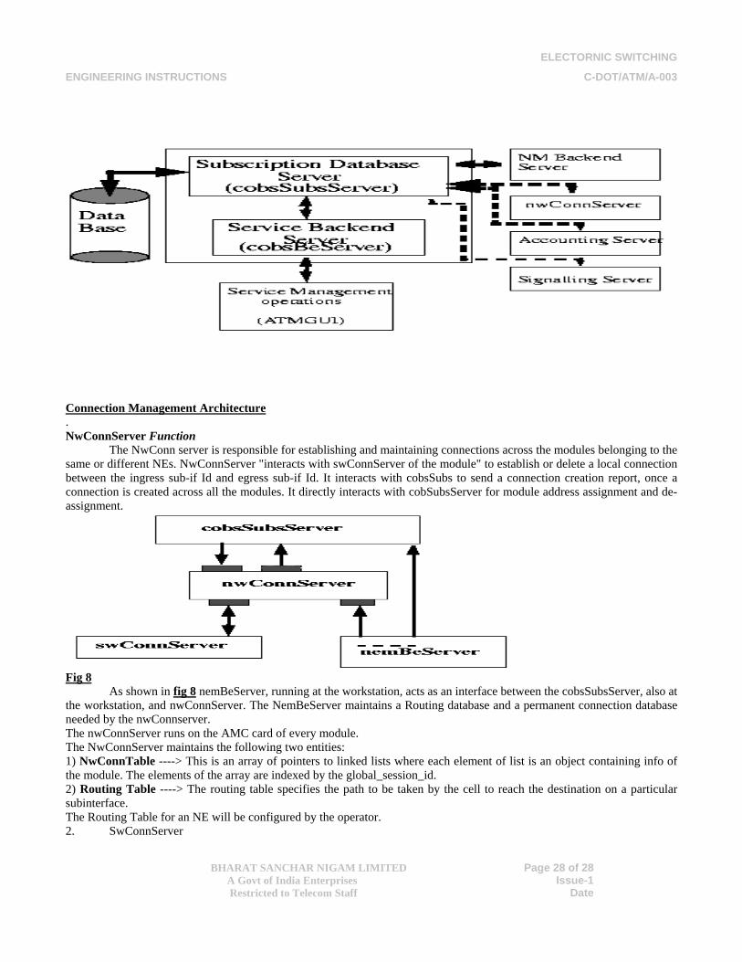
ELECTORNIC SWITCHING
ENGINEERING INSTRUCTIONS C-DOT/ATM/A-003
BHARAT SANCHAR NIGAM LIMITED
A Govt of India Enterprises Restricted to Telecom Staff
Page 28 of 28
Issue-1 Date
Connection Management Architecture . NwConnServer Function
The NwConn server is responsible for establishing and maintaining connections across the modules belonging to the same or different NEs. NwConnServer "interacts with swConnServer of the module" to establish or delete a local connection between the ingress sub-if Id and egress sub-if Id. It interacts with cobsSubs to send a connection creation report, once a connection is created across all the modules. It directly interacts with cobSubsServer for module address assignment and de-assignment.
Fig 8
As shown in fig 8 nemBeServer, running at the workstation, acts as an interface between the cobsSubsServer, also at the workstation, and nwConnServer. The NemBeServer maintains a Routing database and a permanent connection database needed by the nwConnserver. The nwConnServer runs on the AMC card of every module. The NwConnServer maintains the following two entities: 1) NwConnTable ----> This is an array of pointers to linked lists where each element of list is an object containing info of the module. The elements of the array are indexed by the global_session_id. 2) Routing Table ----> The routing table specifies the path to be taken by the cell to reach the destination on a particular subinterface. The Routing Table for an NE will be configured by the operator. 2. SwConnServer
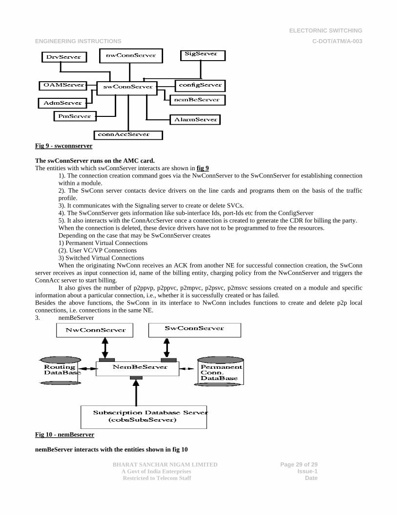
ELECTORNIC SWITCHING
ENGINEERING INSTRUCTIONS C-DOT/ATM/A-003
BHARAT SANCHAR NIGAM LIMITED
A Govt of India Enterprises Restricted to Telecom Staff
Page 29 of 29
Issue-1 Date
Fig 9 - swconnserver The swConnServer runs on the AMC card. The entities with which swConnServer interacts are shown in fig 9
1). The connection creation command goes via the NwConnServer to the SwConnServer for establishing connection within a module. 2). The SwConn server contacts device drivers on the line cards and programs them on the basis of the traffic profile. 3). It communicates with the Signaling server to create or delete SVCs. 4). The SwConnServer gets information like sub-interface Ids, port-Ids etc from the ConfigServer 5). It also interacts with the ConnAccServer once a connection is created to generate the CDR for billing the party. When the connection is deleted, these device drivers have not to be programmed to free the resources. Depending on the case that may be SwConnServer creates 1) Permanent Virtual Connections (2). User VC/VP Connections 3) Switched Virtual Connections When the originating NwConn receives an ACK from another NE for successful connection creation, the SwConn
server receives as input connection id, name of the billing entity, charging policy from the NwConnServer and triggers the ConnAcc server to start billing.
It also gives the number of p2ppvp, p2ppvc, p2mpvc, p2psvc, p2msvc sessions created on a module and specific information about a particular connection, i.e., whether it is successfully created or has failed. Besides the above functions, the SwConn in its interface to NwConn includes functions to create and delete p2p local connections, i.e. connections in the same NE. 3. nemBeServer
Fig 10 - nemBeserver nemBeServer interacts with the entities shown in fig 10
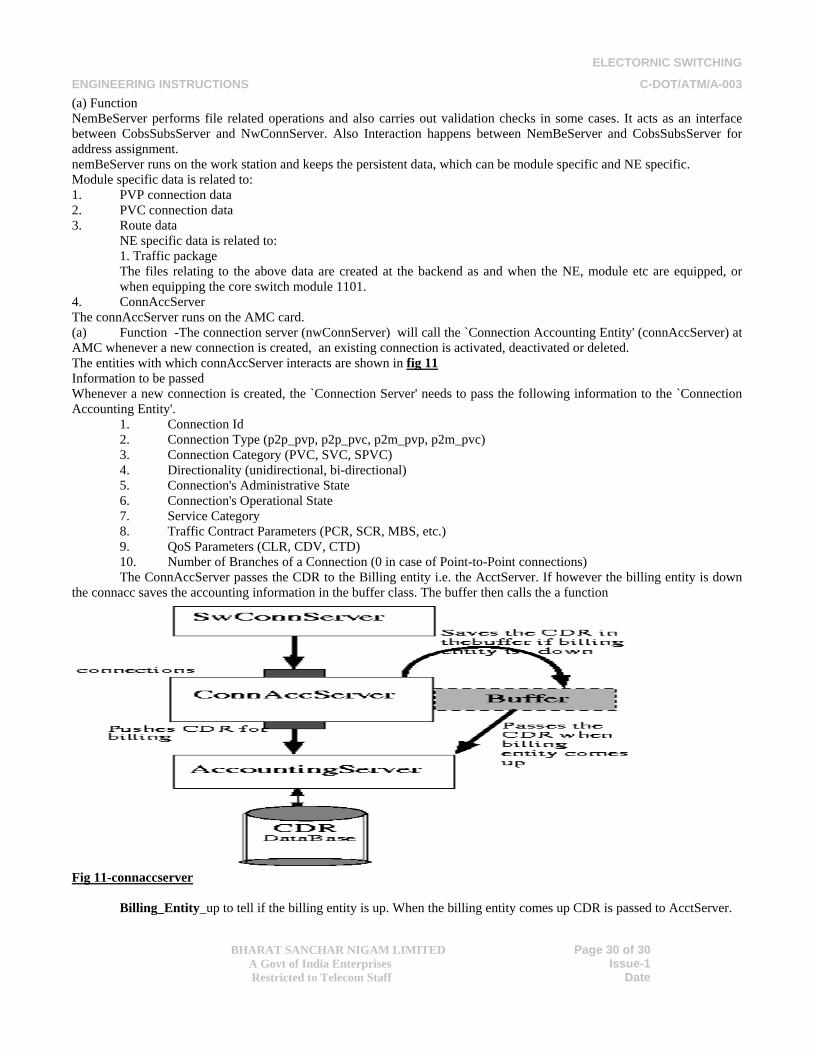
ELECTORNIC SWITCHING
ENGINEERING INSTRUCTIONS C-DOT/ATM/A-003
BHARAT SANCHAR NIGAM LIMITED
A Govt of India Enterprises Restricted to Telecom Staff
Page 30 of 30
Issue-1 Date
(a) Function NemBeServer performs file related operations and also carries out validation checks in some cases. It acts as an interface between CobsSubsServer and NwConnServer. Also Interaction happens between NemBeServer and CobsSubsServer for address assignment. nemBeServer runs on the work station and keeps the persistent data, which can be module specific and NE specific. Module specific data is related to: 1. PVP connection data 2. PVC connection data 3. Route data
NE specific data is related to: 1. Traffic package The files relating to the above data are created at the backend as and when the NE, module etc are equipped, or when equipping the core switch module 1101.
4. ConnAccServer The connAccServer runs on the AMC card. (a) Function -The connection server (nwConnServer) will call the `Connection Accounting Entity' (connAccServer) at AMC whenever a new connection is created, an existing connection is activated, deactivated or deleted. The entities with which connAccServer interacts are shown in fig 11Information to be passed Whenever a new connection is created, the `Connection Server' needs to pass the following information to the `Connection Accounting Entity'.
1. Connection Id 2. Connection Type (p2p_pvp, p2p_pvc, p2m_pvp, p2m_pvc) 3. Connection Category (PVC, SVC, SPVC) 4. Directionality (unidirectional, bi-directional) 5. Connection's Administrative State 6. Connection's Operational State 7. Service Category 8. Traffic Contract Parameters (PCR, SCR, MBS, etc.) 9. QoS Parameters (CLR, CDV, CTD) 10. Number of Branches of a Connection (0 in case of Point-to-Point connections) The ConnAccServer passes the CDR to the Billing entity i.e. the AcctServer. If however the billing entity is down
the connacc saves the accounting information in the buffer class. The buffer then calls the a function
Fig 11-connaccserver
Billing_Entity_up to tell if the billing entity is up. When the billing entity comes up CDR is passed to AcctServer.
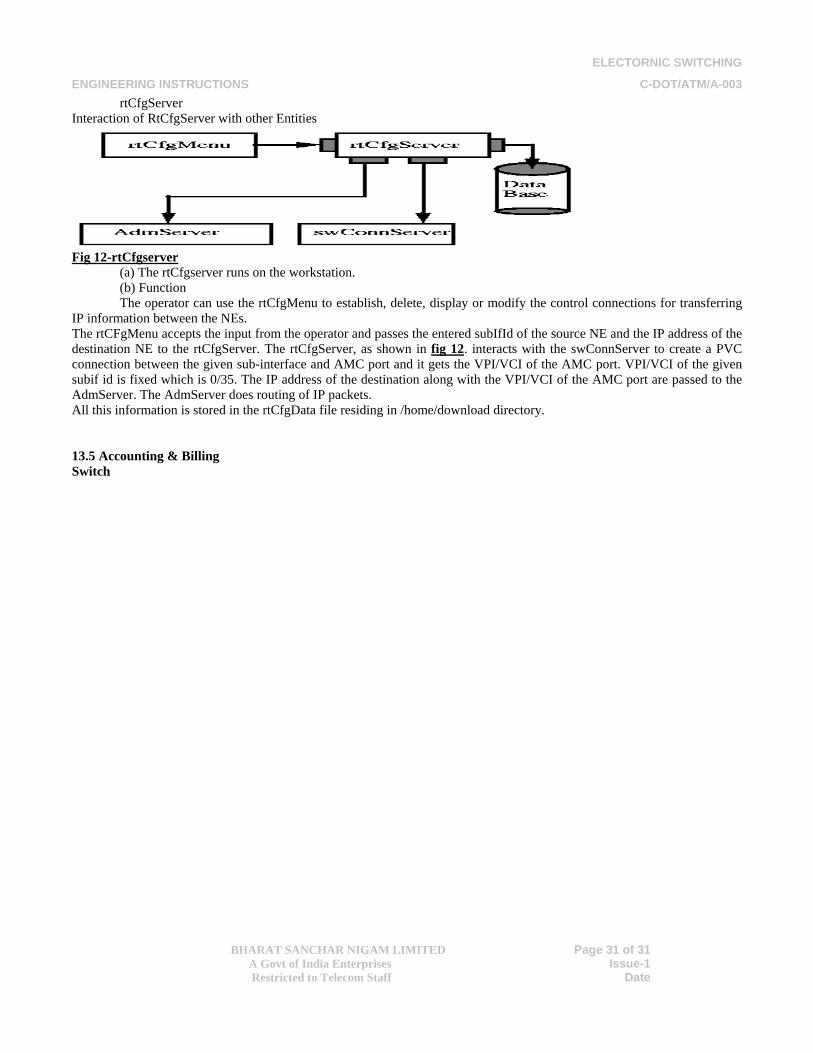
ELECTORNIC SWITCHING
ENGINEERING INSTRUCTIONS C-DOT/ATM/A-003
BHARAT SANCHAR NIGAM LIMITED
A Govt of India Enterprises Restricted to Telecom Staff
Page 31 of 31
Issue-1 Date
rtCfgServer Interaction of RtCfgServer with other Entities
Fig 12-rtCfgserver
(a) The rtCfgserver runs on the workstation. (b) Function The operator can use the rtCfgMenu to establish, delete, display or modify the control connections for transferring
IP information between the NEs. The rtCFgMenu accepts the input from the operator and passes the entered subIfId of the source NE and the IP address of the destination NE to the rtCfgServer. The rtCfgServer, as shown in fig 12. interacts with the swConnServer to create a PVC connection between the given sub-interface and AMC port and it gets the VPI/VCI of the AMC port. VPI/VCI of the given subif id is fixed which is 0/35. The IP address of the destination along with the VPI/VCI of the AMC port are passed to the AdmServer. The AdmServer does routing of IP packets. All this information is stored in the rtCfgData file residing in /home/download directory. 13.5 Accounting & Billing Switch
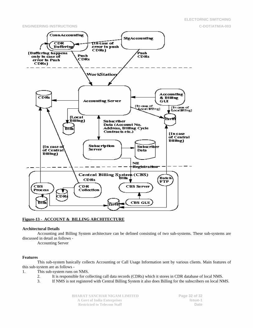
ELECTORNIC SWITCHING
ENGINEERING INSTRUCTIONS C-DOT/ATM/A-003
BHARAT SANCHAR NIGAM LIMITED
A Govt of India Enterprises Restricted to Telecom Staff
Page 32 of 32
Issue-1 Date
Figure-13 - ACCOUNT & BILLING ARCHITECTURE Architectural Details
Accounting and Billing System architecture can be defined consisting of two sub-systems. These sub-systems are discussed in detail as follows - Accounting Server Features
This sub-system basically collects Accounting or Call Usage Information sent by various clients. Main features of this sub-system are as follows - 1. This sub-system runs on NMS.
2. It is responsible for collecting call data records (CDRs) which it stores in CDR database of local NMS. 3. If NMS is not registered with Central Billing System it also does Billing for the subscribers on local NMS.
ELECTORNIC SWITCHING
ENGINEERING INSTRUCTIONS C-DOT/ATM/A-003
BHARAT SANCHAR NIGAM LIMITED
A Govt of India Enterprises Restricted to Telecom Staff
Page 33 of 33
Issue-1 Date
4. While performing billing activity on local NMS it refers to Subscriber database and Tariff Plan database of local NMS.
5. If NMS is registered with Central Billing System it only bears the responsibility of CDR collection. Billing is performed by Central Billing System in such a case. Clients Accounting Server sub-system has three clients -
1. Connection Accounting : This pushes CDRs with Accounting Server for PVC connections. 2. Signaling Accounting : This pushes CDRs with Accounting Server for SVC connections. 3. Accounting & Billing GUI: It also responds to the requests of Accounting & Billing GUI regarding CDRs or Bills on local NMS.
Central Billing System Features This is another sub-system of Accounting & Billing System. This sub-system in turn consists of various processes each of which is described as follows -
1.CDR Collection : This runs at a regular interval and collects CDRs on Central Billing System Workstation from all the registered NMSs. If due to some reason CDRs could not be collected for a particular day CDR Collection process can be forced to collect CDRs by executing it manually. In case of forced CDR collection it is necessary to supply the NE from which CDRs need to be collected and the date for which to collect CDRs 2.CBS Process : This is the main Billing process which generates bills for all the registered NEs and stores Bills on Central Billing System. 3.CBS Server : This process does following tasks - It responds the Register request from NEs. When a NE is successfully registered with Central Billing System, Tariff Plan of Central Billing System is used for calculating bills. Therefore same tariff plan is copied to registered NMS for compatibility. It also responds to various Tariffs, CDRs and Bill related queries from GUI running on Central Billing System. 4CBS GUI : This it the user interface available on Central Billing System. It offers following options - Tariff related operations : Display/Modify operation for Usage and Flat Tariff Plans on Central Billing System. Subscriber Usage Information operations : These operations allow operator to display/backup/print CDRs of subscriber(s) collected on Central Billing System. It also provides operations to display/backup/print Bills generated for subscriber(s) of a particular registered NE.
Extra Features Micro OS feature of Modules (PROM Support). All C-DoT Core Switches/MUX support the micro OS feature. Each card in every module has a 512KB on-board memory known as PROM. It is detachable memory chip and can be programmed through the standard PROM programmer. When card starts functioning, It reads the first memory location which lies in PROM. PROM memory holds the micro version of OS and main activity of micro OS is to download the Main OS from the WS. PROM holds the compact version of full OS. This is why it is called the micro OS. Each card has its own version of Micro OS in which it initializes the on-board devices and provides the bare minimum set of the OS services to download the Main OS. When card downloaded the Main OS from the Workstation. It jumps to Main OS and executing of the Main OS. Card in up state executes in the Main OS. Few points related the PROM should be clear. Each card has its own PROM i.e. Micro version of OS. Two PROMs of the same card can be used interchangeably. Card can not come up without the card specific PROM. Downloading Strategy
Downloading deals with the activity of loading the Main OS in the card. The software that does the downloading is called the downloader. In existing modules, It is necessary part of the Main and Micro OS. Micro OS version downloader downloads the Main OS. While the Main OS downloader facilitates the lower module downloading. In present C-DoT ATM related modules, downloader initializes the devices, selected devices/card if they are more than one and communicates with the other subsystems for normal functioning of the card.
ELECTORNIC SWITCHING
ENGINEERING INSTRUCTIONS C-DOT/ATM/A-003
BHARAT SANCHAR NIGAM LIMITED
A Govt of India Enterprises Restricted to Telecom Staff
Page 34 of 34
Issue-1 Date
Few points are important in regard of downloading strategy. Higher module should be up for making the lower module up. Main controller card is the first in downloading. Front-end card is the next in sequence, this is because of its important role in downloading path. Lower module is connected to the higher module through the front –end card. Rest cards in a module have the same priority and downloading follows the first come first serve principle. Core switch downloads its code from its domain workstation. MUX downloads from the Core switches. can obtain its code from either Core Switch or MUX. 14.0 CONCLUSION The C_DOT developed ATM technology provides wide flexibility to provide data connectivity as per requirements of the customer, as with the advancement of technology, customers are demanding new and varied services in one platform. This is the perfect time for the deployment of C-DOT ATM systems in the country as there is very high demand for data services in the country now and this cost-effective technology is the real answer to appease the demands of the intelligent customer. GLOSSARY OF TERMS USED IN ATM TECHNOLOGY AAL : ATM ADAPTATION LAYER ABR : AVAILABLE BIT RATE ACR : ALLOWED INVERSE CELL RATE ADTF : ACR DECREASE TIME FACTOR AFI : AUTHORITY AND FORMAT IDENTIFIER AHFG : ATM – ATTACHED HOST FUNCTIONAL GROUP AIMUX : ATM MULTIPLEXING AIR : ADDITIVE INCREASE RATE AIRF : ADDITITIVE INCREASE RATE FACTOR AIS : ALARM INDICATION SIGNAL API : ATM APPLICATION PROGRAM INTERFACE ATM – ARP : ATM ADDRESS RESOLUTION PROTOCOL B-ICI : B-ISDN INTER-CARRIER INTERFACE B-ICI SAAL : B-ICI SIGNALLING ATM ADAPTATION LAYER B-ISDN : BROADBAND INTEGRATED SERVICES DIGITAL NETWORK CBR : CONSTAMT BIT RATE CCR : CURRENT CELL RATE CDV : CELL DELAY VARIATION CDVT : CELL DELAY VARIATION TOLERANCE CER : CELL ERROR RATE CES : CIRCUIT EMULATION SERVICE CIP : CARRIER IDENTIFICATION PARAMETER CIR : COMMITTED INFORMATION RATE CLP : CELL LOSS PRIORITY CLR : CELL LOSS RATIO COM : CONTINUATION OF MESSAGE CPCS : COMMON PART CONVERGENCE SUBLAYER CPCS-SDU : COMMON PART CONVERGENCE SUBLAYER – SERVICE DATA UNIT CRF : CONNECTION RELATED FUNCTION CRM : CELL RATE MARGIN CRS : CELL RELAY SERVICE CS : CONVERGENCE SUBLAYER
ELECTORNIC SWITCHING
ENGINEERING INSTRUCTIONS C-DOT/ATM/A-003
BHARAT SANCHAR NIGAM LIMITED
A Govt of India Enterprises Restricted to Telecom Staff
Page 35 of 35
Issue-1 Date
CTD : CELL TRANSFER DELAY DES : DESTINATION END STATION DTL : DESIGNATED TRANSIT LIST DXI : DATA EXCHANGE INTERFACE EFCI : EXPLICIT FORWARD CONGESTION INDICATION EOM : END OF MESSAGE ES : END SYSTEM FC : FEEDBACK CONTROL FUNI : FRAME USER NETWORK INTERFACE HEC : HEADER ERROR CONTROL ILMI : INTEGRATE LOCAL MANAGEMENT INTERFACE IMA : INVERSE MULTIPLEXING OVER ATM I-PNNI : INTEGRATED PRIVATE NETWORK-NETWORK INTERFACE IS : INTERMEDIATE SYSTEM LANE : LAN EMULATION LB : LEAKY BUCKET LECID : LAN EMULATION CLIENT IDENTIFIER LECS : LAN EMULATION CONFIGURATION SERVER LES : LAN EMULATION SERVER LTE : SONET LITE TERMINATING EQUIPMENT M1 : MANAGEMENT INTERFACE 1 MBS : MAXIMUM BURST SIZE MCDV : MAXIMUM CELL DELAY VARIANCE MCLR : MAXIMUM CELL LOSS RATIO MCR : MAXIMUM CELL RATE MCTD : MAXIMUM CELL TRANSFER DELAY MID : MESSAGE IDENTIFIER MPOA : MULTI-PROTOCOL OVER ATM NE : NETWORK ELEMENT NEF : NETWORK ELEMENT FUNCTION NM : NETWORK MANAGEMENT ENTITY NNI : NETWORK NODE INTERFACE OR NETWORK-NETWORK INTERFACE NPC : NETWORK PARAMETER CONTROL NSAP : NETWORK SERVICE ACCESS POINT OAM : OPERATION ADMINISTRATION AND MAINTENANCE PCR : PEAK CELL RATE PDH : PLESIOCHRONOUS DIGITAL HIERARCHY PDU : PROTOCOL DATA UNIT PVC : PERMANENT VIRTUAL CIRCUIT PHY : PHYSICAL LAYER PLCP : PHYSICAL LAYER CONVERGENCE PROTOCOL PNI : PERMIT NEXT INCREASE PNNI : PRIVATE NETWORK-NETWORK INTERFACE PVC : PERMANENT VIRTUAL CONNECTION PVCC : PERMANENT VIRTUAL CHANNEL CONNECTION PVP : PERMANENT VIRTUAL PATH QoS : QUALITY OF SERVICE RDF : RATE DECREASE FACTOR RM : RESOURCE MANAGEMENT RTT : ROUND TRIP TIME SAAL : SIGNALLING ATM ADAPTATION LAYER
ELECTORNIC SWITCHING
ENGINEERING INSTRUCTIONS C-DOT/ATM/A-003
BHARAT SANCHAR NIGAM LIMITED
A Govt of India Enterprises Restricted to Telecom Staff
Page 36 of 36
Issue-1 Date
SCR : SUSTAINABLE CELL RATE SDH : SYNCHRONOUS DIGITAL HIERARCHY SDT : STRUCTURED DATA TRANSFER SE : SWITCHING ELEMENT SEAL : SIMPLE AND EFFICIENT ADAPTATION LAYER SEL : SELECTOR SIPP : SMDS INTERFACE PROTOCOL SMDS : SWITCHED MULTI-MEGABIT DATA SERVICES SN : SEQUENCE NUMBER SNC : SUBNETWORK CONNECTION SONET : SYNCHRONOUS OPTICAL NETWORK SSCF : SERVICE SPECIFIC COORDINATION FUNCTION SVC : SWITCHED VIRTUAL CIRCUIT SVPC : SWITCHED VIRTUAL PATH CONNECTION TC : TRANSMISSION CONVERGENCE TCS : TRANSMISSION CONVERGENCE SUBLAYER TM : TRAFIC MANAGEMENT UBR : UNSPECIFIED BIT RATE UME : UNI MANAGEMENT ENTITY UNI : USER NETWORK INTERFACE UPC : USAGE PARAMETER CONTROL UTOPIA : UNIVERSAL TEST & OPERATIONS INTERFACE FOR ATM VBR : VARIABLE BIT RATE VBR-nrT : VARIABLE BIT RATE NON REAL TIME VBR-RT : VARIABLE BIT RATE REAL TIME VC : VIRTUAL CHANNEL VCC : VIRTUAL CHANNEL CONNECTION VCI : VIRTUAL CHANNEL IDENTIFIER VPC : VIRTUAL PATH CONNECTION VPI : VIRTUAL PATH IDENTIFIER VPL : VIRTUAL APTH LINK VPT : VIRTUAL PATH TERMINATOR VTOA : VOICE AND TELEPHONY OVER ATM DOCUMENTS REFERRED
1. General description of C-DOT ATM SWITCH by C-DOT 2. Network element user guide – configuration management by C-DOT