Embed Size (px)
Citation preview

11
Current Research
at Turbomachinery Aero-Heat Transfer Laboratory
at Penn StateAERONAUTICAL PROPULSION & ENERGY PRODUCTION
Dr. Cengiz Camci
22
TURBOMACHINERY AERO-HEAT TRANSFER LABORATORY
Department of Aerospace Engineering
THE PENNSYLVANIA STATE UNIVERSITY
TEACHING & RESEARCH
Prepared by : Dr. Cengiz Camci
Professor of Aerospace Engineering223 Hammond Building [email protected]
28-KASIM-2007 ODTU
33
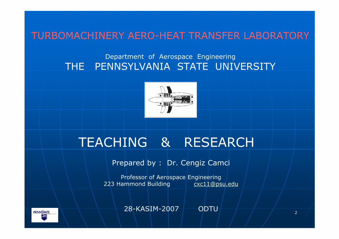
ASTRONAUTICSAERONAUTICS
RESEARCH ACTIVITIESAEROSPACE ENGINEERING DEPARTMENT
SPACE PROPULSION
FLIGHTVEHICLE DESIGN
AIRBREATHING
PROPULSION&
TURBOMACHINERY
AEROACOUSTICS
ROTORCRAFT ENGINEERING
STRUCTURALDYNAMICS
COMPUTING,INFORMATION &
COMMUNICATIONS
EXPERIMENTALCOMPUTATIONAL
ANALYTICALFLUID MECHANICS
SPACECRAFT &
SATELLITE DESIGN
SPACE ENVIRONMENT
&RE-ENTRY
ASTRODYNAMICS
STRUCTURES&
MATERIALS
DYNAMICS&
CONTROLS
COMPUTATIONAL FLUIDS
&RAREFIED GAS
DYNAMICS
44
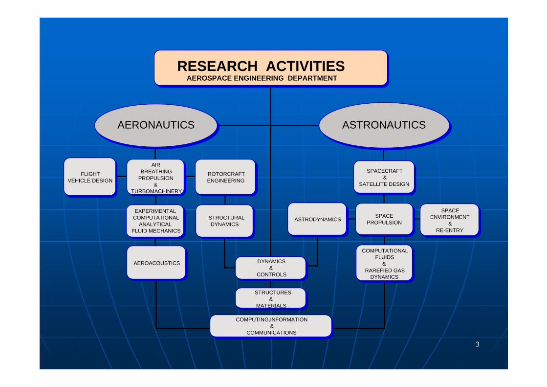
TURBOMACHINERY RELATED TEACHING EFFORTS
�Finite Element Method in Fluid Mechanics and Heat TransferAERSP 560
� Foundations of Fluid Mechanics AERSP 508
� Aerospace Propulsion AERSP 410
� Turbulent Flow AERSP 412
� Theory and Design of Turbomachinery AERSP 507
� Aero-thermo-mechanical Design of Small Gas Turbinesfor UAV Applications AERSP 597-K
� Propulsion System Design and Analysis forUnmanned Air Vehicles AERSP 597-E
55
The objectives of a course and lifelong learning:
TEACHING OBJECTIVES
The objective of a course is
not to cover a certain set of topics,
but rather
to facilitate student learning.

66
but rather with
learning that can be applied and usedin situations outside the course examinations.
Good teachers are not only concerned with the learning of a set of facts,

77
The teachers need to stimulate interest in further learning.
TEACHING OBJECTIVES
The students need to develop skills that will help themin a lifelong learning process.
Offering a base of concepts and skills that will facilitate
further learning and thinkingis an important part of college teaching.
88
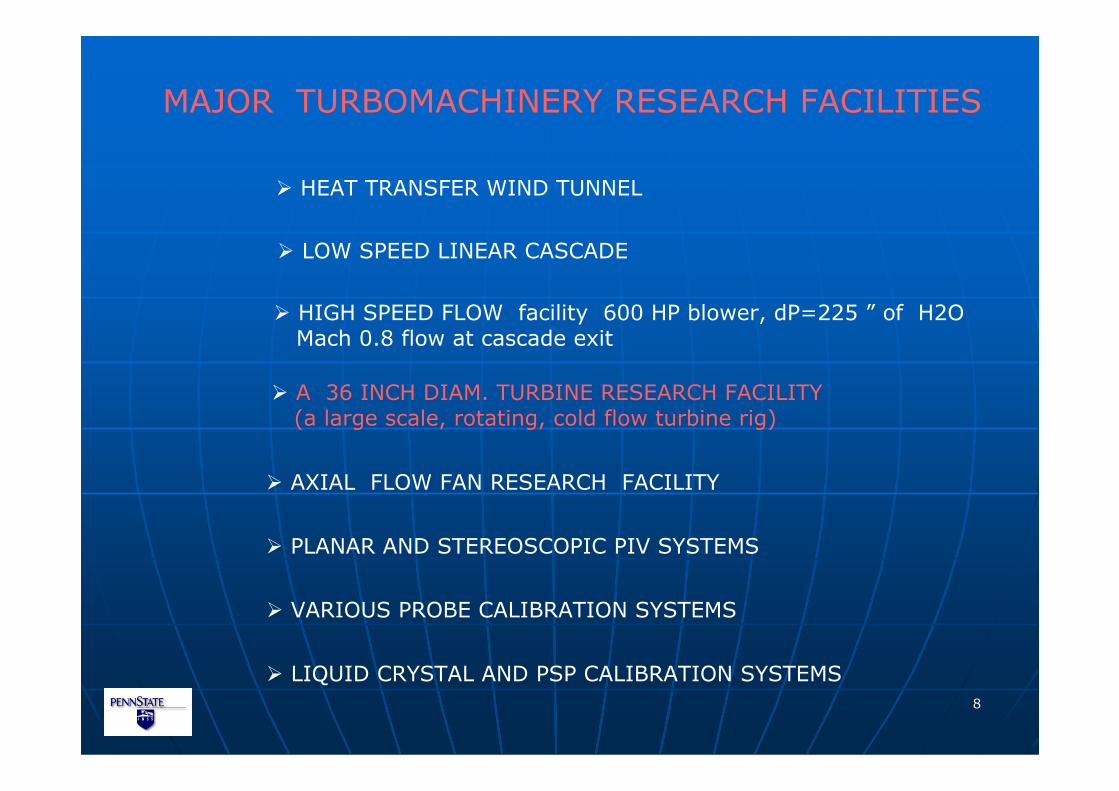
MAJOR TURBOMACHINERY RESEARCH FACILITIES
� HEAT TRANSFER WIND TUNNEL
� LOW SPEED LINEAR CASCADE
� HIGH SPEED FLOW facility 600 HP blower, dP=225 ” of H2OMach 0.8 flow at cascade exit
� A 36 INCH DIAM. TURBINE RESEARCH FACILITY(a large scale, rotating, cold flow turbine rig)
� PLANAR AND STEREOSCOPIC PIV SYSTEMS
� VARIOUS PROBE CALIBRATION SYSTEMS
� LIQUID CRYSTAL AND PSP CALIBRATION SYSTEMS
� AXIAL FLOW FAN RESEARCH FACILITY
99
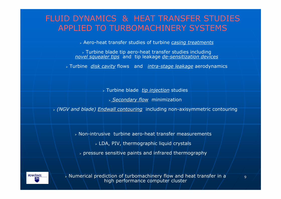
FLUID DYNAMICS & HEAT TRANSFER STUDIESAPPLIED TO TURBOMACHINERY SYSTEMS
� Aero-heat transfer studies of turbine casing treatments
� Turbine blade tip aero-heat transfer studies includingnovel squealer tips and tip leakage de-sensitization devices
� Turbine disk cavity flows and intra-stage leakage aerodynamics
� Turbine blade tip injection studies
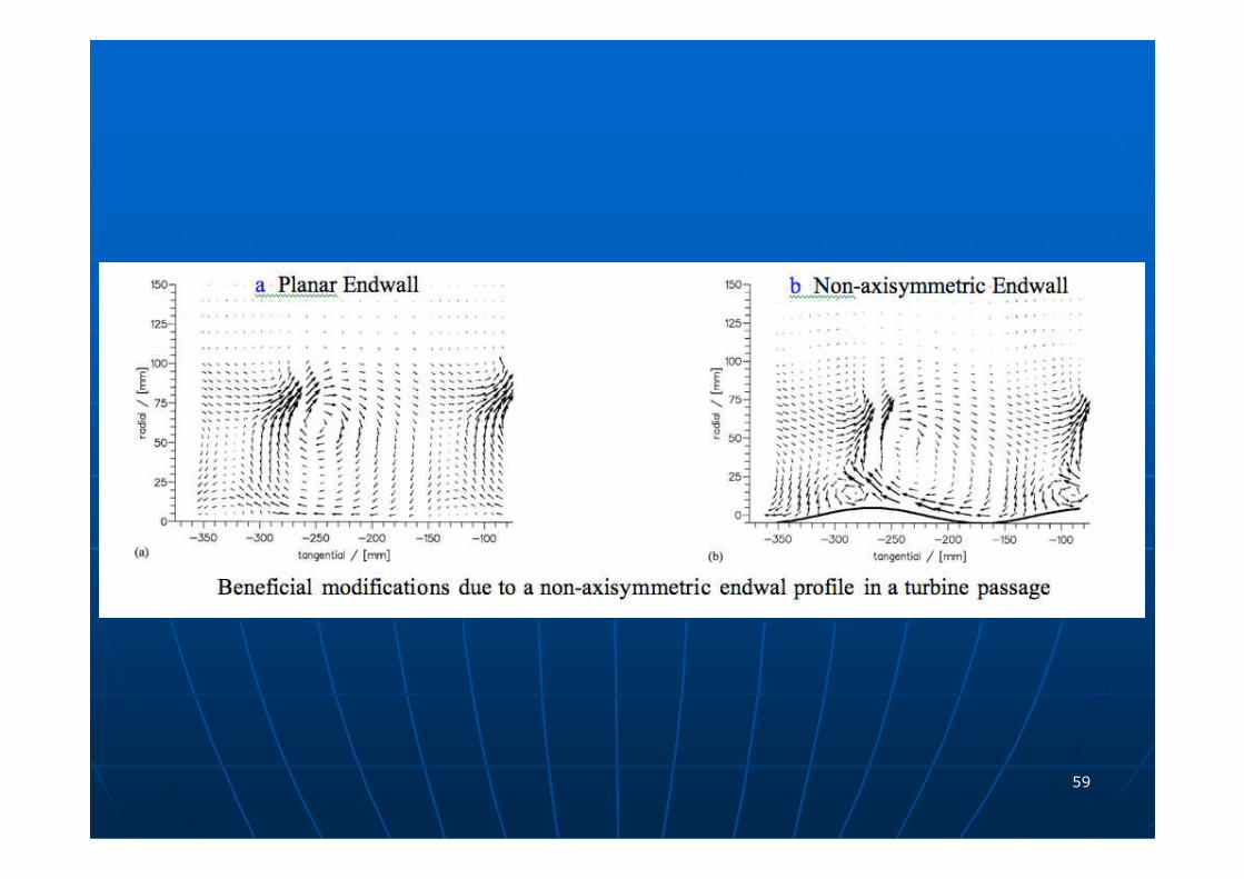
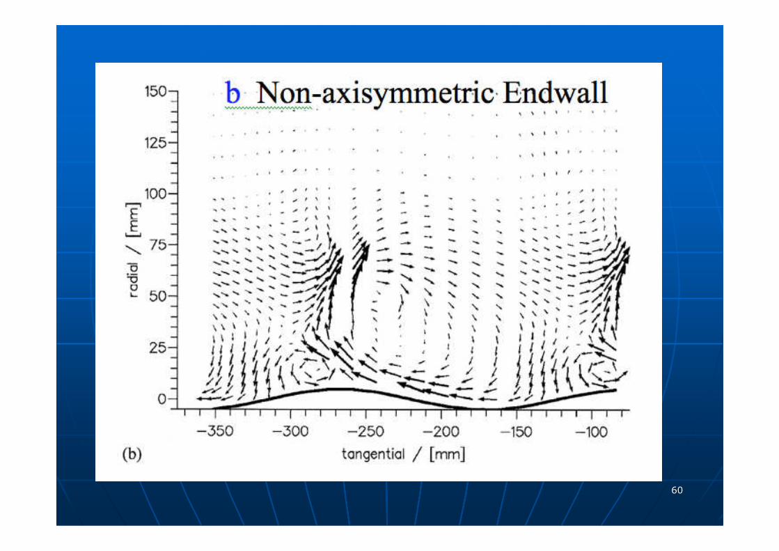
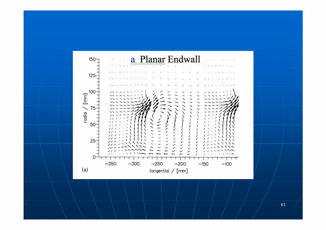
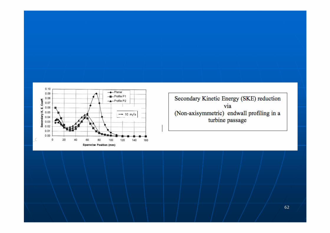
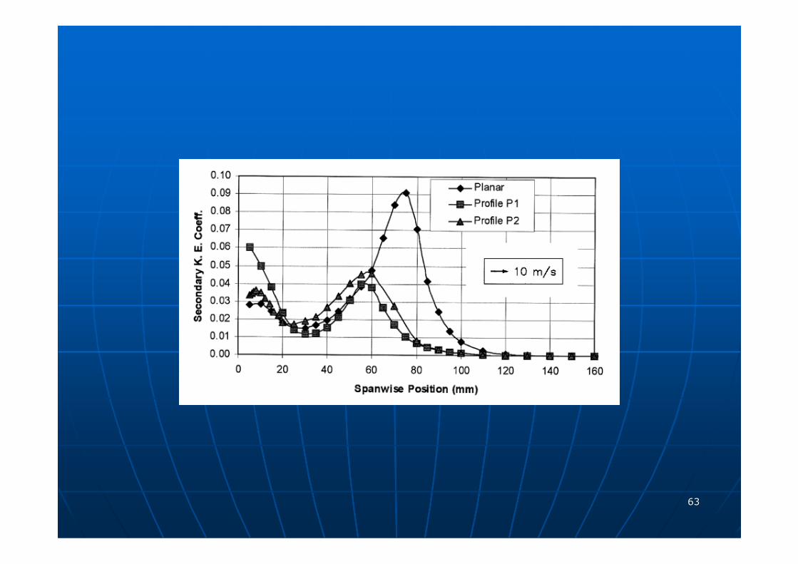
� Secondary flow minimization
� (NGV and blade) Endwall contouring including non-axisymmetric contouring
� Non-intrusive turbine aero-heat transfer measurements
� LDA, PIV, thermographic liquid crystals
� pressure sensitive paints and infrared thermography
� Numerical prediction of turbomachinery flow and heat transfer in ahigh performance computer cluster
1010
Two new projects
funded by :
VERTICAL LIFT ROTORCRAFT CENTER OF EXCELLENCE
VLRCOE (2007)
1. DUCTED FAN AEROYNAMICS
2. HELICOPTER BLADE TIP AERODYNAMICS
1111
Another new project
funded by :
SIEMENS POWER SYSTEMS (2007)
NON-AXISYMMETRICTURBINE ENDWALL CONTOURING
Secondary flow minimization inturbine passages (NGV)
1212
For further details contact to Dr.Cengiz CamciDept. of Aerospace Engineering
814 865 9871
http://www.personal.psu.edu/cxc11/AFTRF
TURBOMACHINERY AERO-HEAT TRANSFER LABORATORY
Dept.of Aerospace Engineering

1313
1414
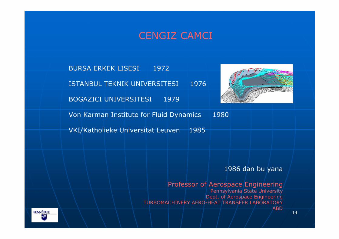
CENGIZ CAMCI
BURSA ERKEK LISESI 1972
ISTANBUL TEKNIK UNIVERSITESI 1976
BOGAZICI UNIVERSITESI 1979
Von Karman Institute for Fluid Dynamics 1980
VKI/Katholieke Universitat Leuven 1985
1986 dan bu yana
Professor of Aerospace EngineeringPennsylvania State University
Dept. of Aerospace EngineeringTURBOMACHINERY AERO-HEAT TRANSFER LABORATORY
ABD

1515
1616
AERO-THERMAL STUDIES ATPSU TURBOMACHINERY AERO-HEAT TRANSFER
LABORATORY
Sponsor: DOE/DOD GT companies
Dr. Cengiz Camci Prof. of Aerospace Eng.
Objective :
Improving energy efficiency of turbomachinery systems through
aerodynamic and heat transfer related performance gains.
1717
AERO-THERMAL STUDIES ATPSU TURBOMACHINERY AERO-HEAT TRANSFER LABORATORY
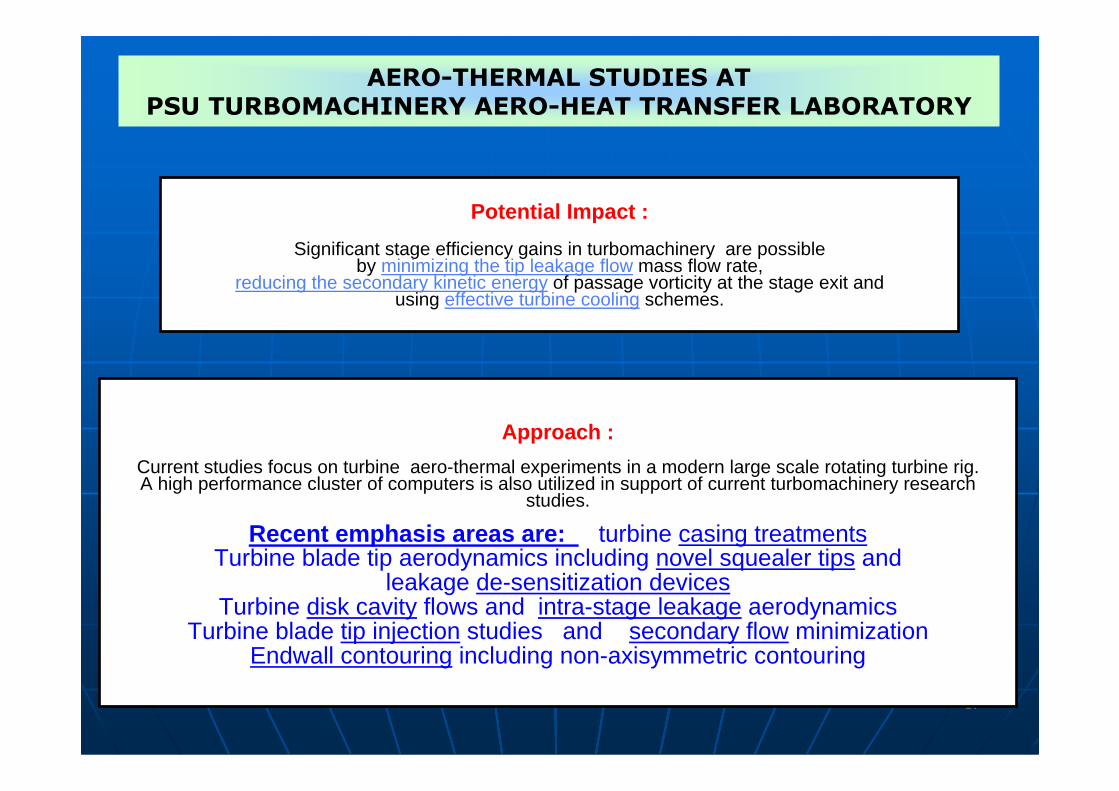
Approach :
Current studies focus on turbine aero-thermal experiments in a modern large scale rotating turbine rig.A high performance cluster of computers is also utilized in support of current turbomachinery research
studies.
Recent emphasis areas are: turbine casing treatmentsTurbine blade tip aerodynamics including novel squealer tips and
leakage de-sensitization devicesTurbine disk cavity flows and intra-stage leakage aerodynamics
Turbine blade tip injection studies and secondary flow minimizationEndwall contouring including non-axisymmetric contouring
Potential Impact :
Significant stage efficiency gains in turbomachinery are possibleby minimizing the tip leakage flow mass flow rate,
reducing the secondary kinetic energy of passage vorticity at the stage exit andusing effective turbine cooling schemes.
1818
DUCTED FAN RESEARCH FOR MAV/OAV
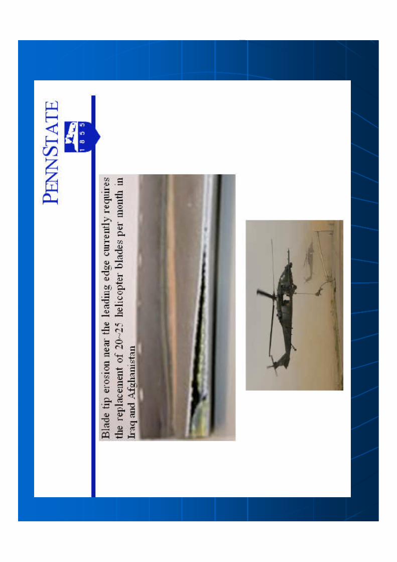
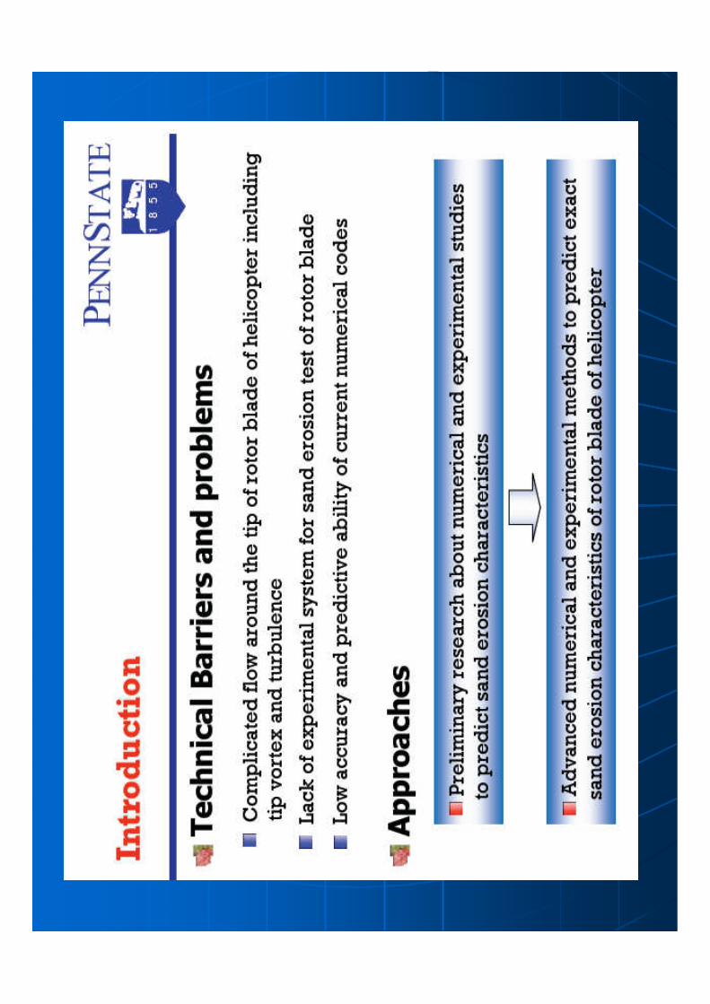
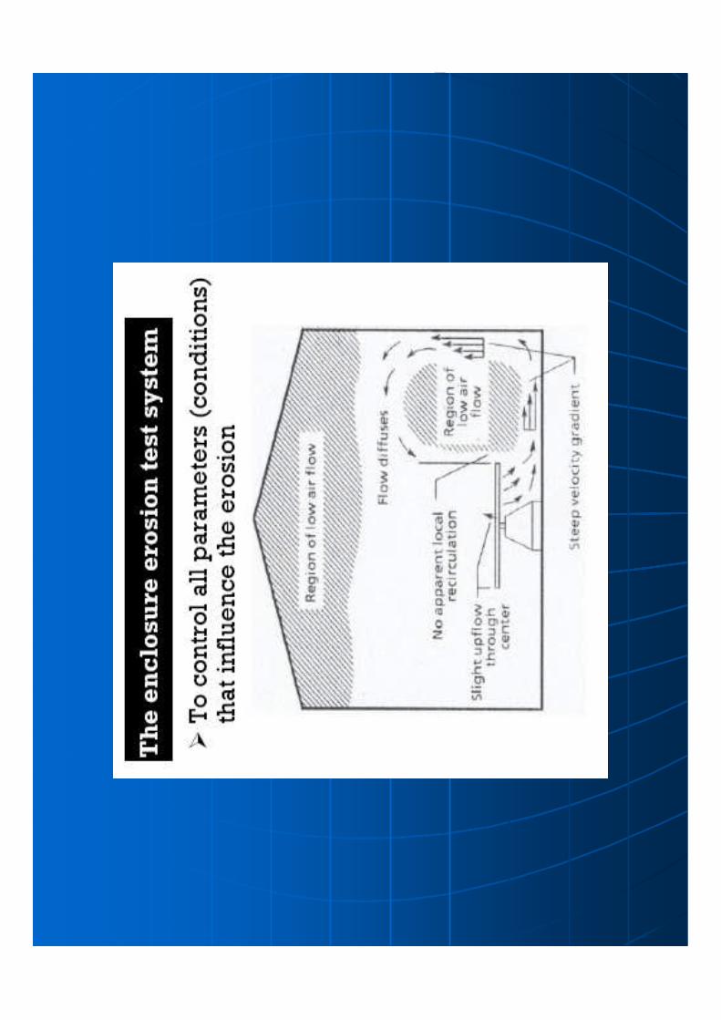
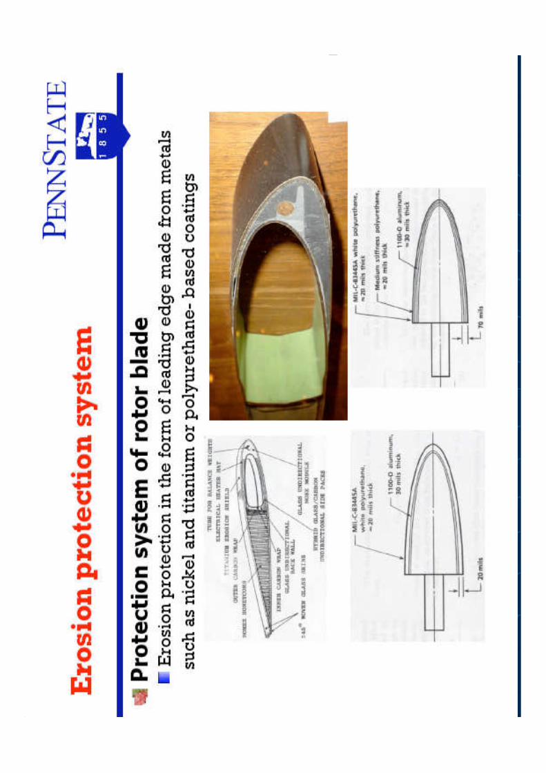
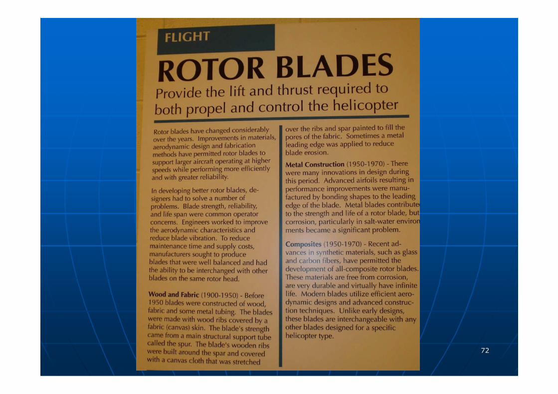
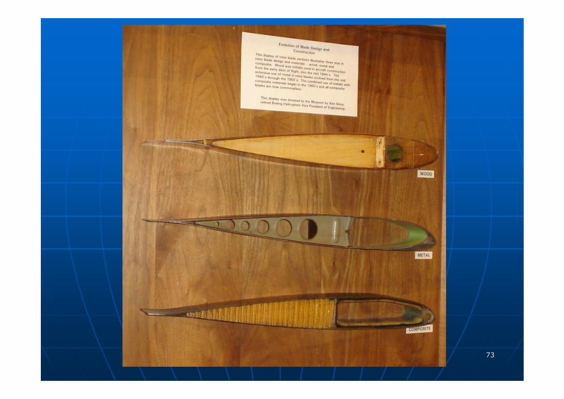
SAND EROSION OF HELICOPTER BLADES
NON-AXISYMMETRIC TURBINE ENDWALL PROFILING
EMERGING AREAS
2007
1919
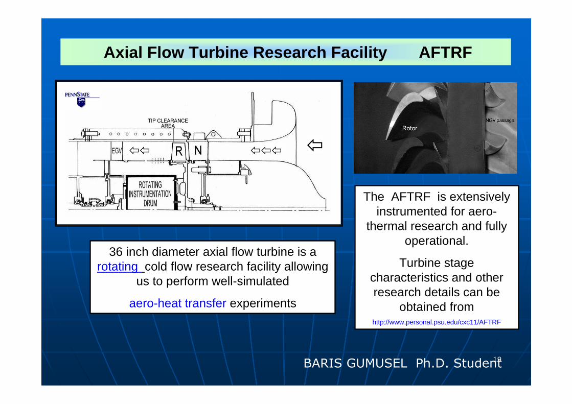
36 inch diameter axial flow turbine is a rotating cold flow research facility allowing
us to perform well-simulated
aero-heat transfer experiments
The AFTRF is extensively instrumented for aero-
thermal research and fully operational.
Turbine stage characteristics and other research details can be
obtained fromhttp://www.personal.psu.edu/cxc11/AFTRF
Axial Flow Turbine Research Facility AFTRF
����� �
BARIS GUMUSEL Ph.D. Student

2020
Phase-locked LDA measurements showing the tip
vortices and passage vortex system in the AFTRF © ASME.
AFTRFDetailed aero-thermal stage flow physics
Fully instrumented and equipped with non-intrusive measurement systems
2121
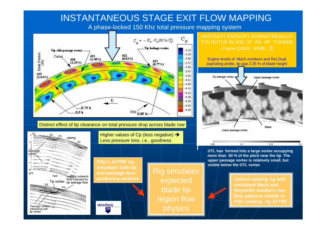
PSU’s AFTRF rig simulates both tip and passage loss producing vortices
Distinct effect of tip clearance on total pressure drop across blade row
--
Higher values of Cp (less negative) �Less pressure loss, i.e., goodness
INSTANTANEOUS STAGE EXIT FLOW MAPPINGA phase-locked 150 Khz total pressure mapping system
Rig simulates expected blade tip
region flow physics
UNSTEADY ENTROPY DOWNSTREAM OF THE ROTOR BLADE OF AN HP TURBINE
, Payne (2003) ASME ©
Engine levels of Mach numbers and Re) Dual aspirating probe, tip gap 2.25 % of blade height
OTL has formed into a large vortex occupying more than 50 % of the pitch near the tip. The upper passage vortex is relatively small, but visible below the OTL vortex
Oxford rotating rig with simulated Mach and Reynolds numbers has flow patterns similar to PSU rotating rig AFTRF
2222
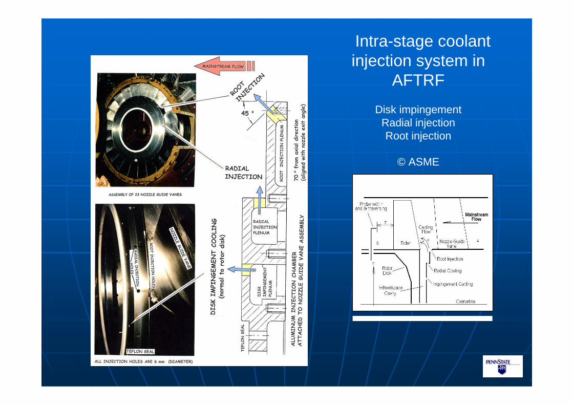
Intra-stage coolant injection system in
AFTRF
Disk impingementRadial injectionRoot injection
© ASME
2323
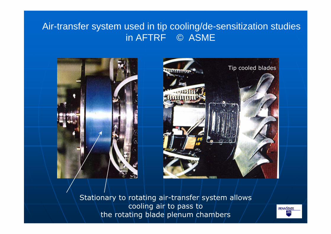
Air-transfer system used in tip cooling/de-sensitization studiesin AFTRF © ASME
Stationary to rotating air-transfer system allowscooling air to pass to
the rotating blade plenum chambers
Tip cooled blades

2424
AFTRF Air-transfer system details © ASME
2525
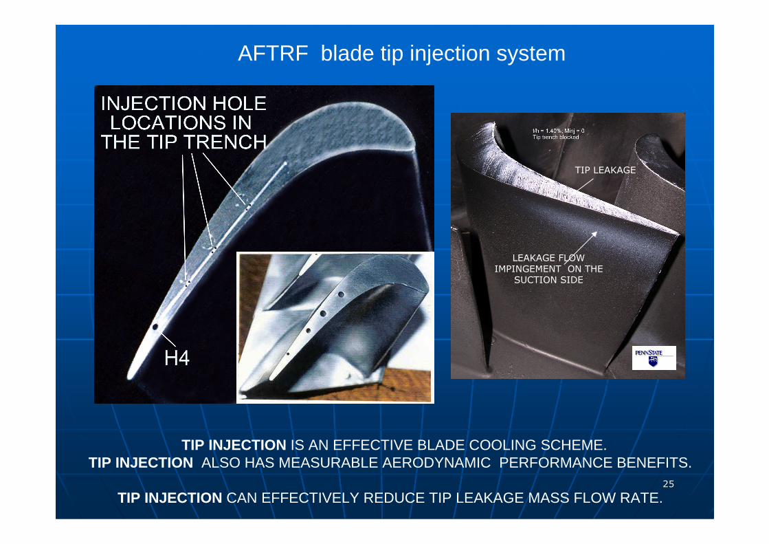
AFTRF blade tip injection system
TIP INJECTION IS AN EFFECTIVE BLADE COOLING SCHEME.TIP INJECTION ALSO HAS MEASURABLE AERODYNAMIC PERFORMANCE BENEFITS.
TIP INJECTION CAN EFFECTIVELY REDUCE TIP LEAKAGE MASS FLOW RATE.
LEAKAGE FLOWIMPINGEMENT ON THE
SUCTION SIDE
TIP LEAKAGE
2626
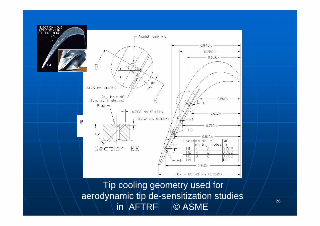
Tip cooling geometry used foraerodynamic tip de-sensitization studies
in AFTRF © ASME
2727
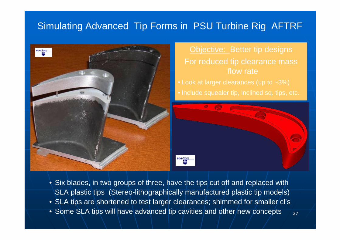
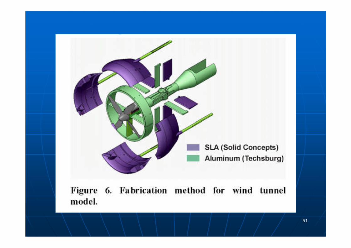
Simulating Advanced Tip Forms in PSU Turbine Rig AFTRF
• Six blades, in two groups of three, have the tips cut off and replaced withSLA plastic tips (Stereo-lithographically manufactured plastic tip models)
• SLA tips are shortened to test larger clearances; shimmed for smaller cl’s• Some SLA tips will have advanced tip cavities and other new concepts
Objective: Better tip designs
For reduced tip clearance mass flow rate
• Look at larger clearances (up to ~3%)
• Include squealer tip, inclined sq. tips, etc.
2828
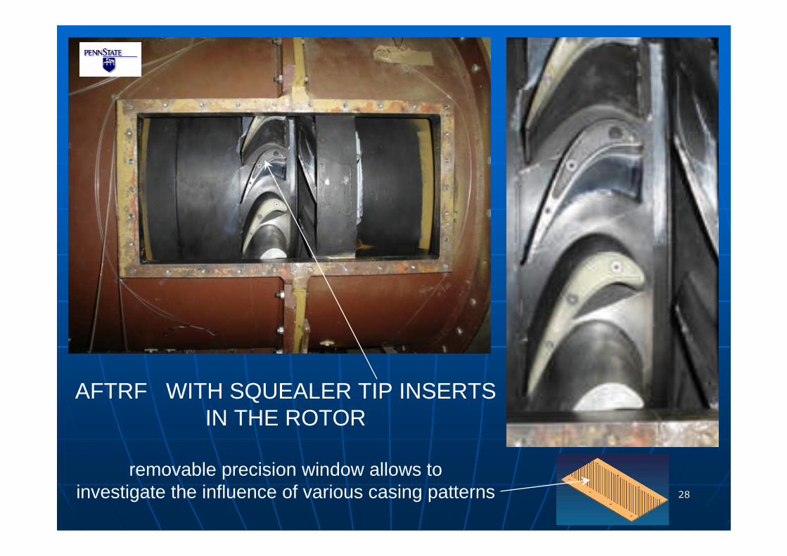
AFTRF WITH SQUEALER TIP INSERTSIN THE ROTOR
removable precision window allows toinvestigate the influence of various casing patterns
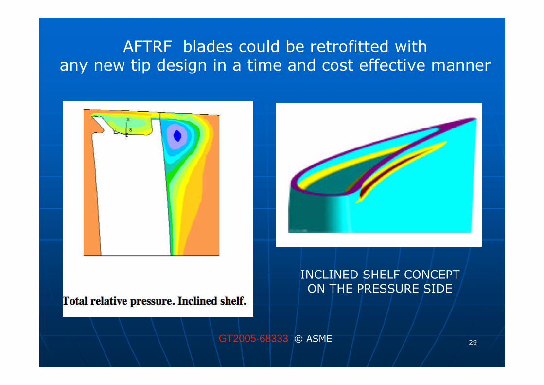
2929GT2005-68333 © ASME
AFTRF blades could be retrofitted withany new tip design in a time and cost effective manner
INCLINED SHELF CONCEPTON THE PRESSURE SIDE
3030
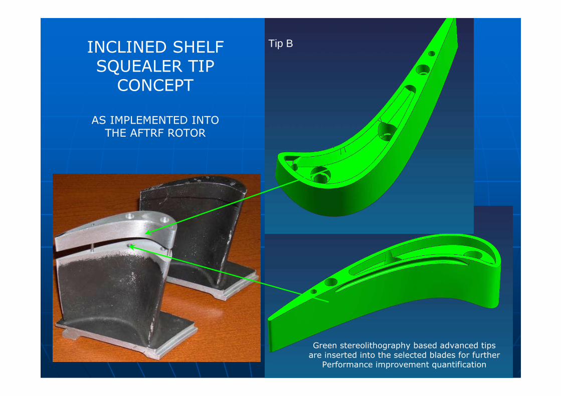
Tip BINCLINED SHELFSQUEALER TIPCONCEPT
AS IMPLEMENTED INTOTHE AFTRF ROTOR
Green stereolithography based advanced tipsare inserted into the selected blades for further
Performance improvement quantification
3131
Aero-heat transfer studies of turbine casing treatments
Turbine blade tip aero-heat transfer studies includingnovel squealer tips and tip leakage de-sensitization devices
Turbine disk cavity flows and intra-stage leakage aerodynamics
Turbine blade tip injection studies
Secondary flow minimization
(NGV and blade) Endwall contouring including non-axisymmetric contouring
Non-intrusive turbine aero-heat transfer measurementsincluding, LDA, PIV, thermographic liquid crystals, pressure sensitive paints and
infrared thermography
Numerical prediction of turbomachinery flow and heat transfer in a high performance computer
Recent emphasis areas are:
3232
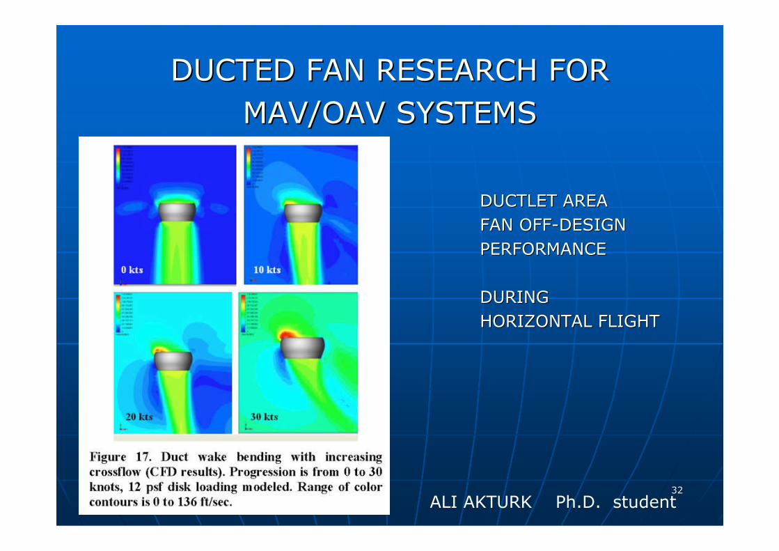
ALI AKTURK Ph.D. student
DUCTED FAN RESEARCH FORDUCTED FAN RESEARCH FOR
MAV/OAV SYSTEMSMAV/OAV SYSTEMS
DUCTLET AREADUCTLET AREA
FAN OFFFAN OFF--DESIGNDESIGN
PERFORMANCEPERFORMANCE
DURINGDURING
HORIZONTAL FLIGHTHORIZONTAL FLIGHT
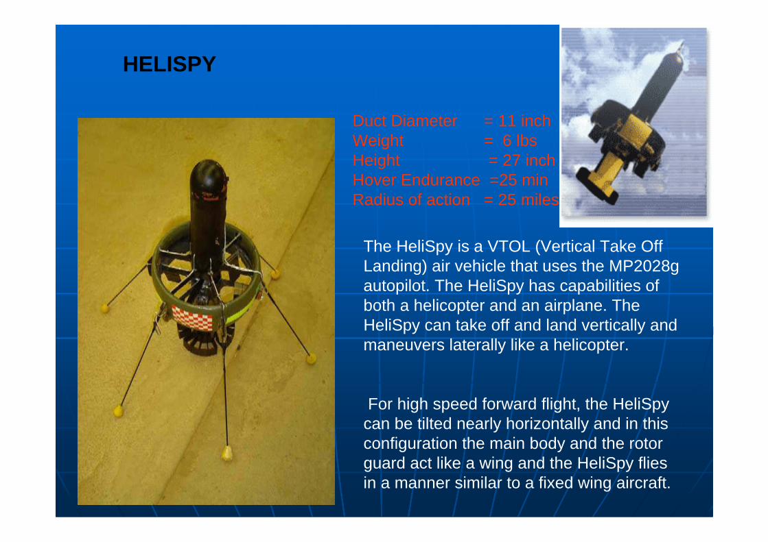
The HeliSpy is a VTOL (Vertical Take Off Landing) air vehicle that uses the MP2028g autopilot. The HeliSpy has capabilities of both a helicopter and an airplane. The HeliSpy can take off and land vertically and maneuvers laterally like a helicopter.
For high speed forward flight, the HeliSpycan be tilted nearly horizontally and in this configuration the main body and the rotor guard act like a wing and the HeliSpy flies in a manner similar to a fixed wing aircraft.
HELISPY
Duct Diameter = 11 inchWeight = 6 lbsHeight = 27 inchHover Endurance =25 minRadius of action = 25 miles
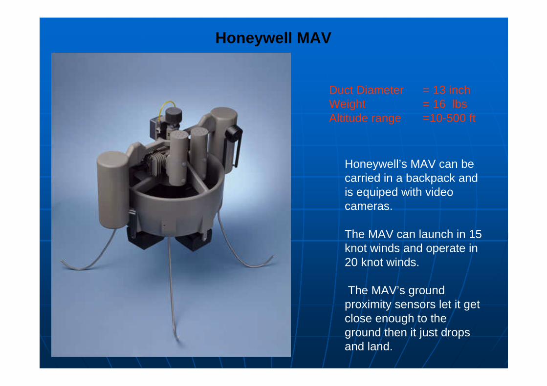
Honeywell’s MAV can be carried in a backpack and is equiped with video cameras.
The MAV can launch in 15 knot winds and operate in 20 knot winds.
The MAV’s ground proximity sensors let it get close enough to the ground then it just drops and land.
Honeywell MAV
Duct Diameter = 13 inchWeight = 16 lbsAltitude range =10-500 ft
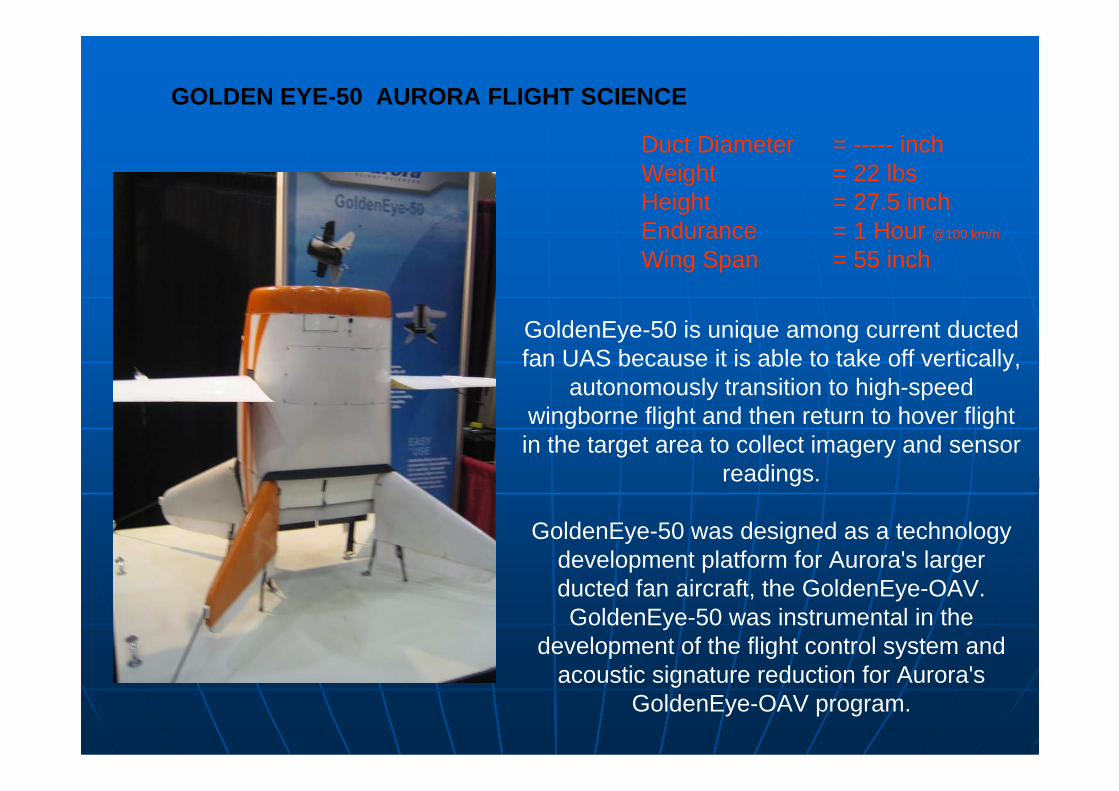
GoldenEye-50 is unique among current ducted fan UAS because it is able to take off vertically,
autonomously transition to high-speed wingborne flight and then return to hover flight in the target area to collect imagery and sensor
readings.
GoldenEye-50 was designed as a technology development platform for Aurora's larger ducted fan aircraft, the GoldenEye-OAV. GoldenEye-50 was instrumental in the
development of the flight control system and acoustic signature reduction for Aurora's
GoldenEye-OAV program.
GOLDEN EYE-50 AURORA FLIGHT SCIENCE
Duct Diameter = ----- inchWeight = 22 lbsHeight = 27.5 inchEndurance = 1 Hour @100 km/h
Wing Span = 55 inch
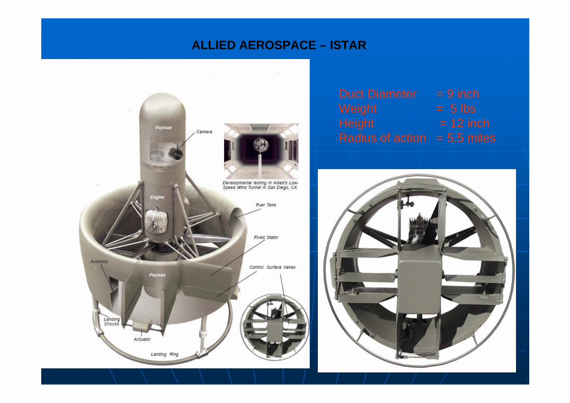
ALLIED AEROSPACE – ISTAR
Duct Diameter = 9 inchWeight = 5 lbsHeight = 12 inchRadius of action = 5.5 miles
3737
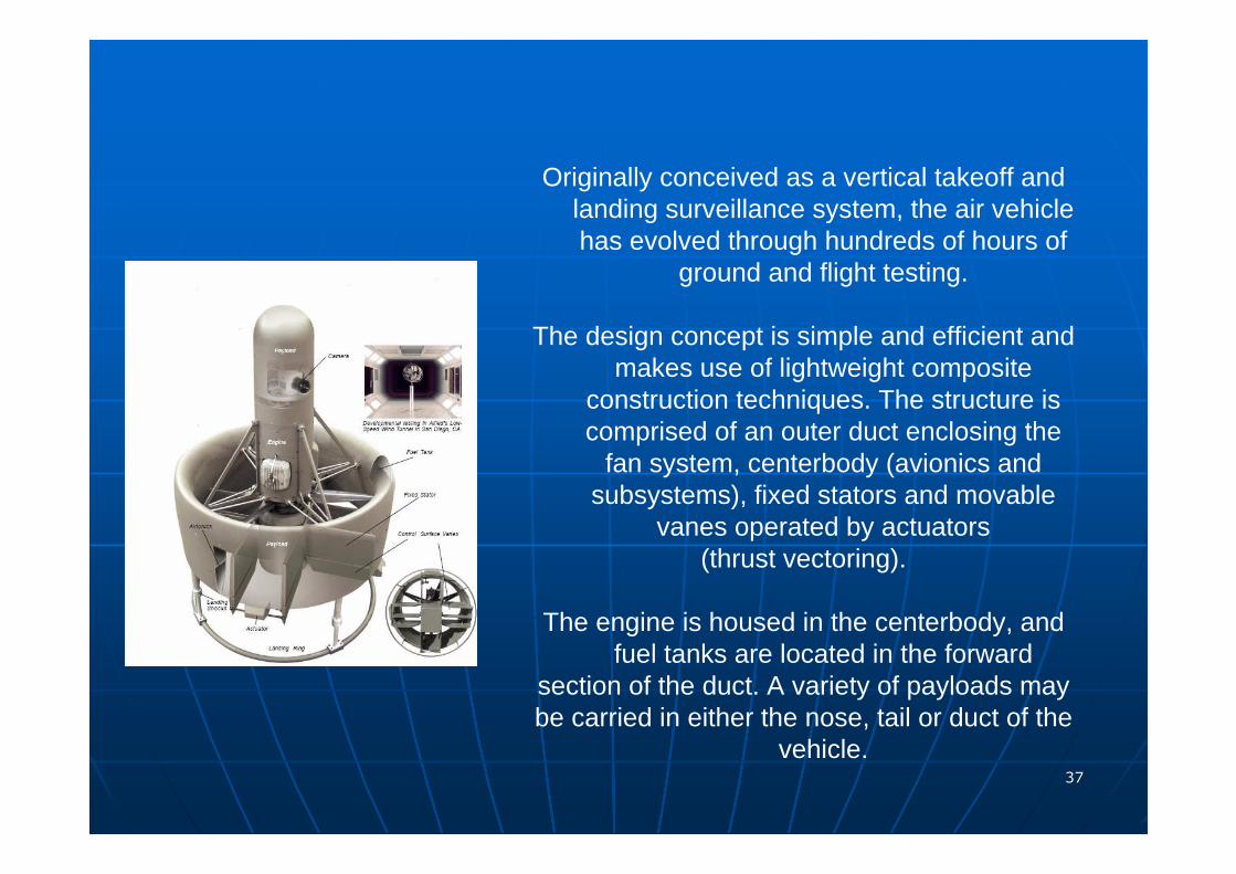
Originally conceived as a vertical takeoff and landing surveillance system, the air vehicle has evolved through hundreds of hours of
ground and flight testing.
The design concept is simple and efficient and makes use of lightweight composite
construction techniques. The structure is comprised of an outer duct enclosing the
fan system, centerbody (avionics and subsystems), fixed stators and movable
vanes operated by actuators(thrust vectoring).
The engine is housed in the centerbody, and fuel tanks are located in the forward
section of the duct. A variety of payloads maybe carried in either the nose, tail or duct of the
vehicle.
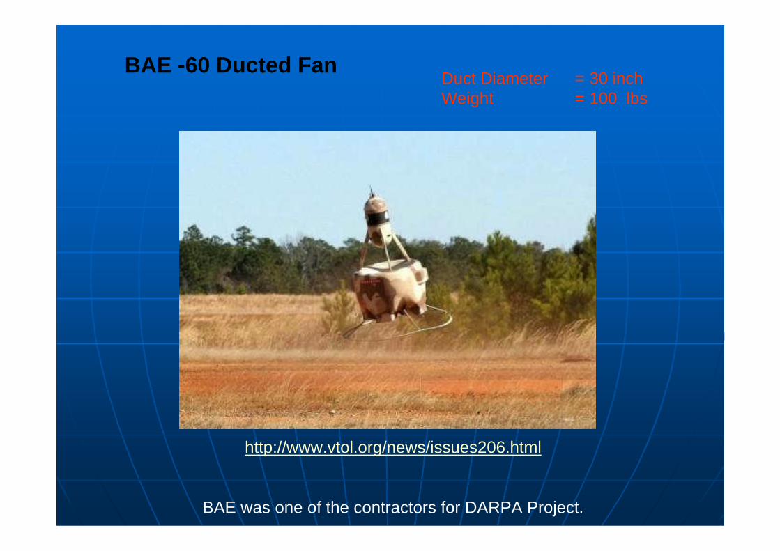
BAE -60 Ducted FanDuct Diameter = 30 inchWeight = 100 lbs
http://www.vtol.org/news/issues206.html
BAE was one of the contractors for DARPA Project.
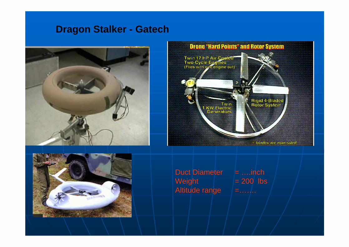
Dragon Stalker - Gatech
Duct Diameter = ….inchWeight = 200 lbsAltitude range =…….
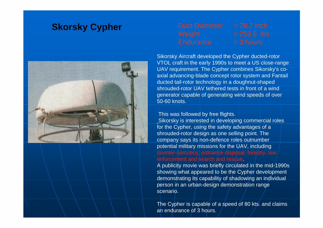
Sikorsky Aircraft developed the Cypher ducted-rotor VTOL craft in the early 1990s to meet a US close-range UAV requirement. The Cypher combines Sikorsky's co-axial advancing-blade concept rotor system and Fantail ducted tail-rotor technology in a doughnut-shaped shrouded-rotor UAV tethered tests in front of a wind generator capable of generating wind speeds of over 50-60 knots.
This was followed by free flights.Sikorsky is interested in developing commercial roles
for the Cypher, using the safety advantages of a shrouded-rotor design as one selling point. The company says its non-defence roles outnumber potential military missions for the UAV, including counter-narcotics, ordnance disposal, forestry, law enforcement and search and rescue.A publicity movie was briefly circulated in the mid-1990s showing what appeared to be the Cypher development demonstrating its capability of shadowing an individual person in an urban-design demonstration range scenario.
The Cypher is capable of a speed of 80 kts. and claims an endurance of 3 hours.
Skorsky Cypher Duct Diameter = 78.7 inchWeight = 253.5 lbsEndurance = 3 hours
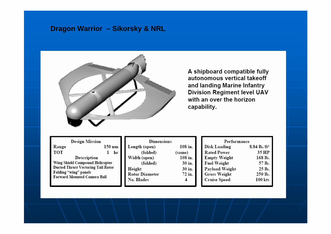
Dragon Warrior – Sikorsky & NRL
Duct Diameter = 9 inchWeight = 5 lbsHeight = 12 inchRadius of action = 5.5 miles
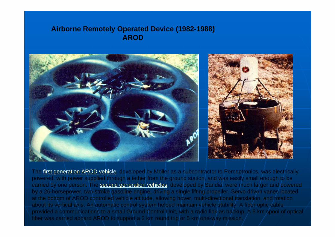
Airborne Remotely Operated Device (1982-1988) �
AROD
The first generation AROD vehicle, developed by Moller as a subcontractor to Perceptronics, was electrically powered, with power supplied through a tether from the ground station, and was easily small enough to be carried by one person. The second generation vehicles, developed by Sandia, were much larger and powered by a 26-horsepower, two-stroke gasoline engine, driving a single lifting propeller. Servo driven vanes located at the bottom of AROD controlled vehicle attitude, allowing hover, multi-directional translation, and rotation about its vertical axis. An automatic control system helped maintain vehicle stability. A fiber optic cable provided a communications to a small Ground Control Unit, with a radio link as backup. A 5 km spool of optical fiber was carried aboard AROD to support a 2 km round trip or 5 km one-way mission.
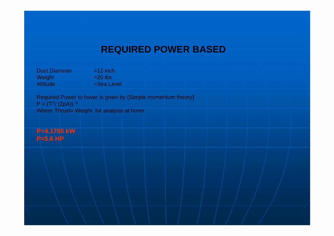
REQUIRED POWER BASED
Duct Diameter =12 inchWeight =20 lbsAltitude =Sea Level
Required Power to hover is given by (Simple momentum theory)�P = (T3 / (2ρA)) ½
Where Thrust= Weight for analysis at hover
P=4.1765 kWP=5.6 HP
FAN & PROPELLER MANUFATURERS
http://www.hoverhawk.com/
http://www.powerfinprops.com/
http://www.warpdriveprops.com/index.html
4545
4646
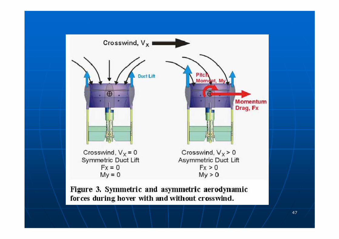
4747
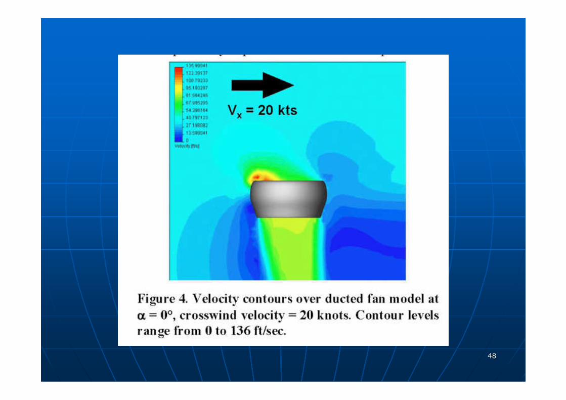
4848
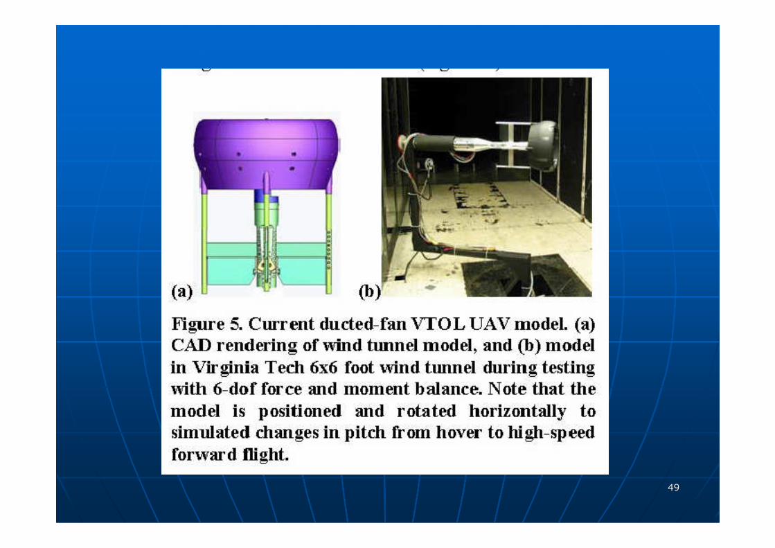
4949
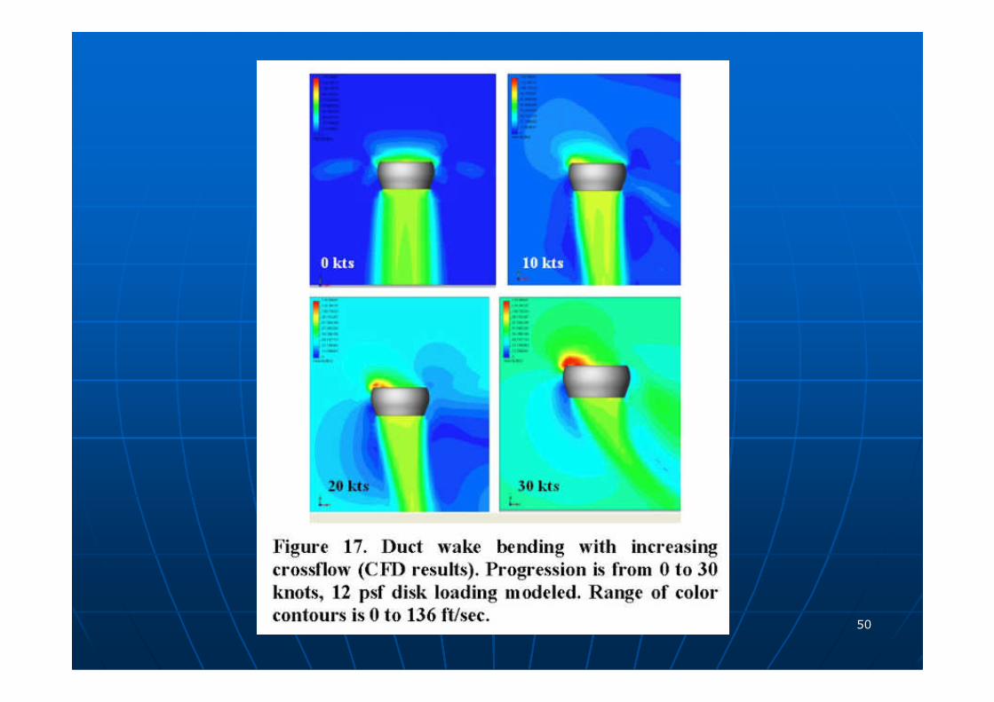
5050
5151
5252
5353
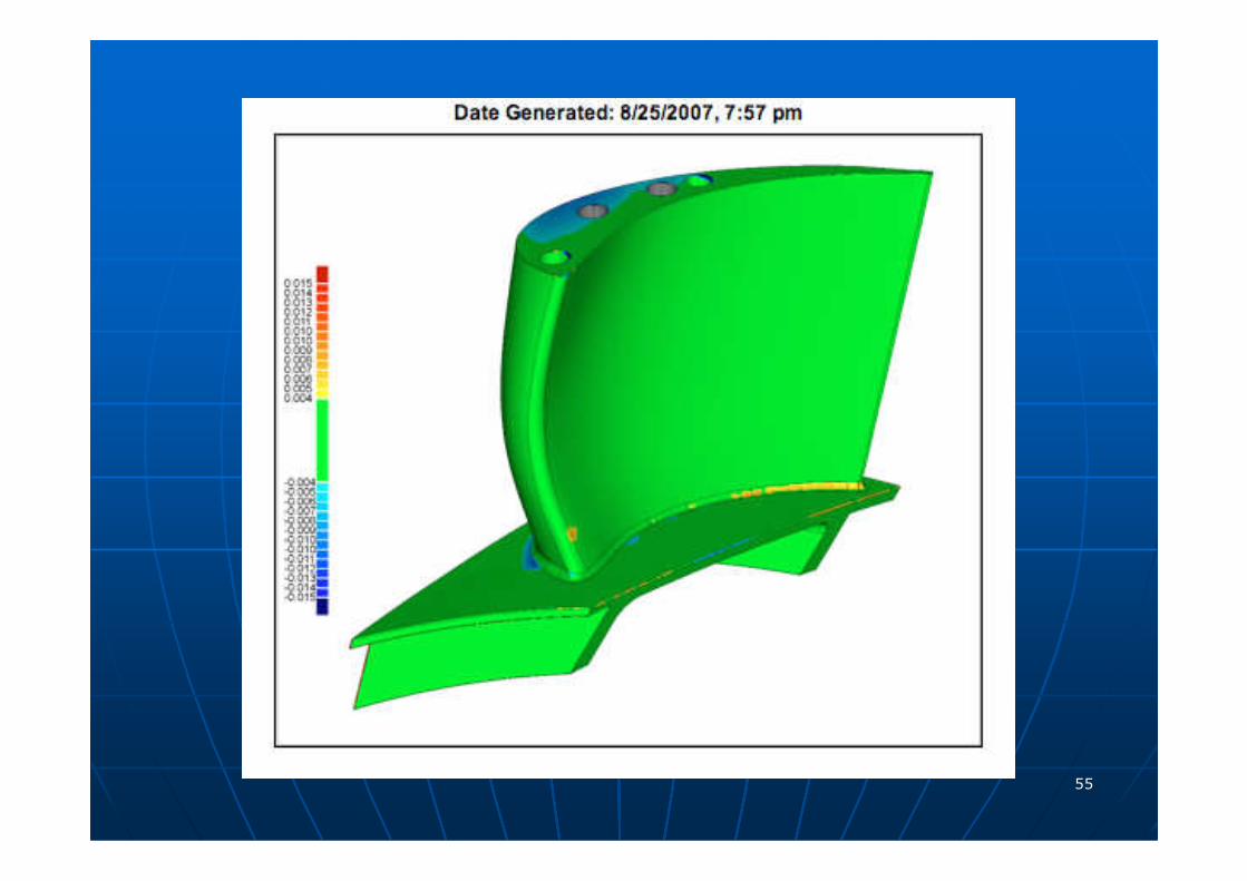
NONNON--AXISYMMETRICAXISYMMETRIC
TURBINE ENDWALL PROFILINGTURBINE ENDWALL PROFILING
IN AXIAL FLOW TURBINESIN AXIAL FLOW TURBINES
�� HOT SECTIONHOT SECTION
�� HP TURBINEHP TURBINE
OZHAN TURGUT Ph.D. student
5454
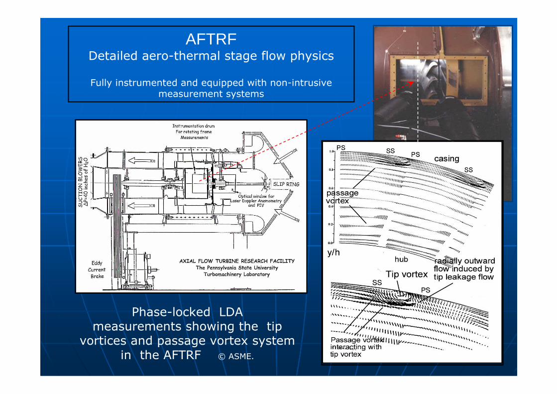
Phase-locked LDA measurements showing the tip
vortices and passage vortex system in the AFTRF © ASME.
AFTRFDetailed aero-thermal stage flow physics
Fully instrumented and equipped with non-intrusive measurement systems
5555
5656
5757
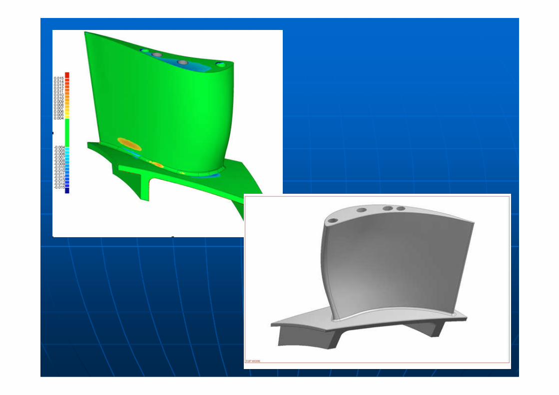
5858
5959
6060
6161
6262
6363


7272
7373
7474
7575
7676
7777
7878
7979
For further details contact to Dr.Cengiz Camci
Dept. of Aerospace Engineering
The Pennsylvania State University
[email protected] 814 865 9871
http://www.personal.psu.edu/cxc11/AFTRF


![The effect of manipulatives on mathematics …akademikpersonel.kocaeli.edu.tr/zeynel.kablan/sci/zeynel.kablan04... · Download by: [Kocaeli Universitesi] Date: 04 January 2017, At:](https://img.pdfslide.us/doc/110x75/5b9704da09d3f2501c8be7a2/the-effect-of-manipulatives-on-mathematics-download-by-kocaeli-universitesi.jpg)