Embed Size (px)
Citation preview
Calhoun: The NPS Institutional Archive
Theses and Dissertations Thesis Collection
1997-12
Current and future efforts to vary the level of detail
for the common operational picture
Hager, Richard S.
Monterey, California. Naval Postgraduate School
http://hdl.handle.net/10945/8179


NAVAL POSTGRADUATE SCHOOLMonterey, California
THESIS
CURRENT AND FUTURE EFFORTS TO VARY THELEVEL OF DETAIL FOR THE COMMON
OPERATIONAL PICTURE
by
Richard S. Hager
December 1997
Thesis Co-Advisors: Gary R. Porter
William G. Kemple
Approved for public release; distribution is unlimited.

REPORT DOCUMENTATION PAGE Form Approved OMB No. 0704-0188
Public reporting burden for this collection of information is estimated to average 1 hour per response, including the time for reviewing instruction, searching existing data sources,
gathering and maintaining the data needed, and completing and reviewing the collection of information. Send comments regarding this burden estimate or any other aspect of this
collection of information, including suggestions for reducing this burden, to Washington Headquarters Services, Directorate for Information Operations and Reports, 1215
Jefferson Davis Highway, Suite 1204, Arlington, VA 22202-4302, and to the Office of Management and Budget, Paperwork Reduction Project (0704-0188) Washington DC20503
1 . AGENCY USE ONLY (Leave blank) REPORT DATEDecember 1997
3. REPORT TYPE AND DATES COVEREDMaster's Thesis
4. title and subtitle TITLE OF THESIS: CURRENT ANDFUTURE EFFORTS TO VARY THE LEVEL OF DETAILFOR THE COMMON OPERATIONAL PICTURE
6. AUTHOR Hager, Richard S.
FUNDING NUMBERS
7. PERFORMING ORGANIZATION NAME(S) AND ADDRESS(ES)
Naval Postgraduate School
Monterey CA 93943-5000
PERFORMINGORGANIZATIONREPORT NUMBER
9. SPONSORING/MONITORING AGENCY NAME(S) AND ADDRESS(ES) 10. SPONSORING/MONITORINGAGENCY REPORT NUMBER
11. SUPPLEMENTARY NOTES The views expressed in this thesis are those of the author and do not reflect the
official policy or position of the Department of Defense or the U.S. Government.
12a. DISTRIBUTION/AVAILABILITY STATEMENTApproved for public release; distribution is unlimited.
12b. DISTRIBUTION CODE
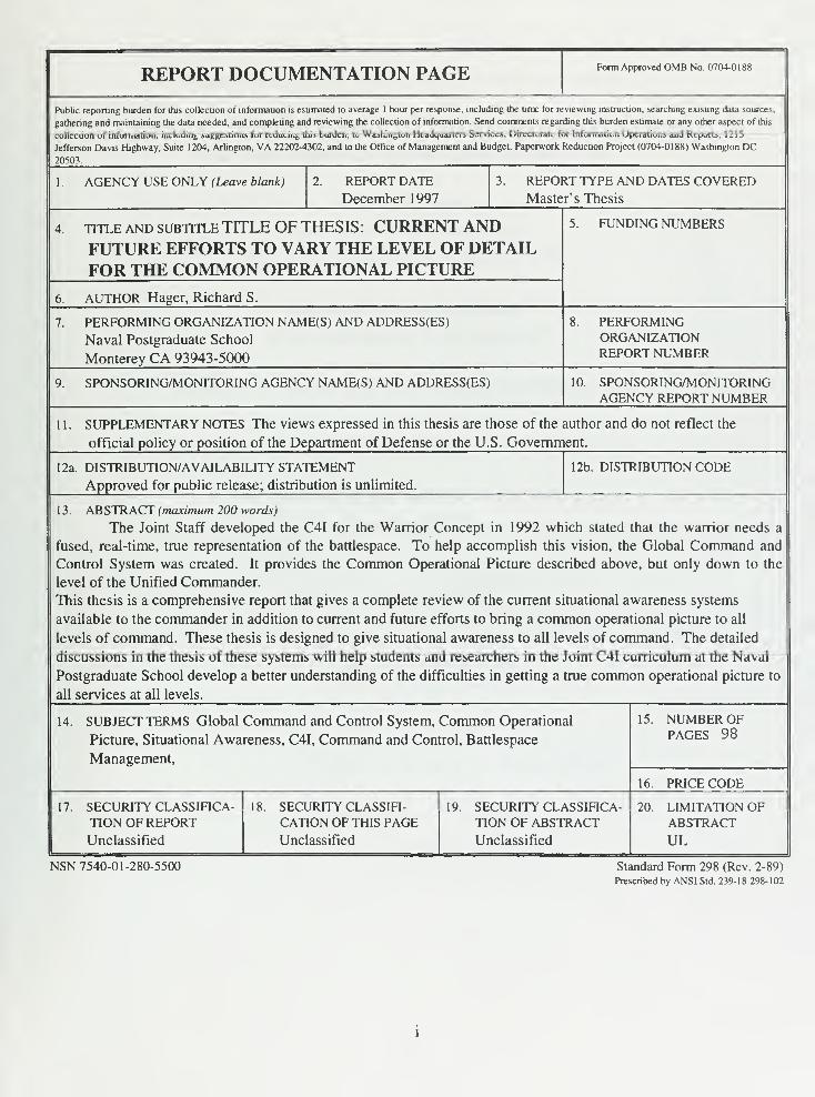
1 3 . ABSTRACT (maximum 200 words)
The Joint Staff developed the C4I for the Warrior Concept in 1992 which stated that the warrior needs a
fused, real-time, true representation of the battlespace. To help accomplish this vision, the Global Command and
Control System was created. It provides the Common Operational Picture described above, but only down to the
level of the Unified Commander.
This thesis is a comprehensive report that gives a complete review of the current situational awareness systems
available to the commander in addition to current and future efforts to bring a common operational picture to all
levels of command. These thesis is designed to give situational awareness to all levels of command. The detailed
discussions in the thesis of these systems will help students and researchers in the Joint C4I curriculum at the Naval
Postgraduate School develop a better understanding of the difficulties in getting a true common operational picture to
all services at all levels.
14. SUBJECT TERMS Global Command and Control System, Common Operational
Picture, Situational Awareness, C4I, Command and Control, Battlespace
Management,
15. NUMBER OFPAGES 98
16. PRICE CODE
17. SECURITY CLASSIFICA-
TION OF REPORTUnclassified
SECURITY CLASSIFI-
CATION OF THIS PAGEUnclassified
19. SECURITY CLASSIFICA-
TION OF ABSTRACTUnclassified
20. LIMITATION OFABSTRACTUL
NSN 7540-01-280-5500 Standard Form 298 (Rev. 2-89)
Prescribed by ANSI Std. 239-18 298-102

II
Approved for public release; distribution is unlimited.
CURRENT AND FUTURE EFFORTS TO VARY THE LEVEL OF DETAILFOR THE COMMON OPERATIONAL PICTURE
Richard S. Hager
Lieutenant, United States Navy
B.S., United States Naval Academy, 1990
Submitted in partial fulfillment
of the requirements for the degree of
MASTER OF SCIENCE IN SYSTEMS TECHNOLOGY
from the
NAVAL POSTGRADUATE SCHOOLDecember 1997

HAQ>£jf
ABSTRACT
The Joint Staff developed the C4I for the Warrior Concept in 1992 which stated
that the warrior needs a fused, real-time, true representation of the battlespace. To help
accomplish this vision, the Global Command and Control System was created. It
provides the Common Operational Picture described above, but only down to the Unified
Commander.
This thesis is a comprehensive report that gives a complete review of the current
situational awareness systems available to the commander in addition to current and
future efforts to bring a common operational picture to all levels of command. These
systems are designed to give situational awareness to all levels of command. The detailed
discussions in the thesis of these systems will help students and researchers in the Joint
C4I curriculum at the Naval Postgraduate School develop a better understanding of the
difficulties in getting a true common operational picture to all services at all levels.

VI
TABLE OF CONTENTS
I INTRODUCTION 1
A. BACKGROUND 1
B. PURPOSE 4
C. THE NEED FOR A COMMON OPERATIONAL PICTURE 5
D. THESIS ORGANIZAITON 6
II CURRENT SITUATIONAL AWARENESS SYSTEMS AVAILABLE TO THECOMMANDER 9
A. AIR FORCE 9
1. Contingency Theater Automated Planning System 9
2. Joint Force Air Component Command Situational Awareness
System 11
B. ARMY 11
1. Automated Digital Data System 12
2. Army Tactical Command and Control System 12
3. All Source Analysis System 13
4. Forward Area Air Defense Command, Control and Intelligence.. 15
5. Maneuver Control System 16
6. Standard Theater Army Command and Control System 17
C JOINT 18
1. Joint Tactical Information Distribution System 18
D. NAVY AND MARINE CORPS 19
1. Joint Maritime Command Information System 19
2. Navy Tactical Data System 20
m THE GLOBAL COMMAND AND CONTROL SYSTEM 21
A. C4I FOR THE WARRIOR 21
B. MIDTERM FIX 23
C. DEFENSE INFORMATION INFRASTRUCTURE 25
D. COMMON OPERATING ENVIRONMENT 26
E. COMMON OPERATIONAL PICTURE 28
F. LEVEL OF DETAIL 29
1. Army and Marine Corps 31
2. Air Force 31
3. Navy 32
G. REPORTING PROCEDURES 32
1. Air Component 33
2. Ground Component 33
3. Naval Component 34
4
.
Joint Special Operation Task Forces Commander 34
5. Special Interest Forces and Tracks 35
H. TRACK REPORTING 35
1. Enhanced Position Location Reporting System 35
vn
2. Officer in Tactical Command Information Exchange System 36
3. Situational Awareness Beacon with Reply 37
4. Tactical Digital Information Links 37
5. Tactical Information Broadcast System 38
6. Tactical Related Applications 39
7. TRI-Service Tactical Communications System 39
I. TRACK FUSION 39
1. Joint Force Commander 41
2. Air Component Commander 41
3. Ground C oiponent Commander 41
4. Maritime Component Commander 42
IV CURRENT EFFORTS 43
A. AIR FORCE 43
B. ARMY 44
1. Army Global Command and Control System 45
2. Force XXI Battle Command, Brigade and Below 46
C. MARINE CORPS 50
1. Marine Air Ground Task Force C4I 50
2. Tactical Combat Operations System 51
D. NAVY 52
1. Force Threat Evaluation and Weapons Assignment 52
V FUTURE EFFORTS 55
A. AIR FORCE 55
1. New World Vistas Global Awareness Virtual Testbed 55
B. ARMY 56
1. Army Battlefield Command System 56
C. DEFENSE ADVANCE RESEARCH PROJECT AGENCY (DARPA) ..61
1. Battlefield Awareness and Data Dissemination 62
D. JOINT 64
1. Advanced Battlespace Information System 65
E. MARINE CORPS 68
1
.
Command and Control Personal Computer 68
F. NAVY 69
VI CONCLUSIONS AND RECOMMENDATIONS 71
A. CONCLUSION 71
B. RECOMMENDATIONS 72
LIST OF REFERENCES 75
INITIAL DISTRIBUTION LIST. 79
Vlll
LIST OF ABBREVIATIONS AND ACRONYMS
ABCSABISACCACEACTDADADDSAGDBAGCCSAORARGASASATCCSATOAWACSAWIS
Army Battle Command System
Advanced Battlespace Information System
Air Component CommanderAnalysis and Control Element
Advanced Concept Technology Demonstration
Air Defense
Automated Digital Data System
Army Global Data Base
Army Global Command and Control System
Area of Responsibility
Amphibious Readiness Group
All Source Analysis System
Army Tactical Command and Control System
Air Tasking Order
Airborne Warning and Control System
Army Worldwide Military Command and Control
Information System
B2C2BADDBFABFACSBOSBUU
Battalion and Below Command and Control System
Battlefield Awareness and Data Dissemination
Battlefield Functional Area
Battlefield Functional Area Control System
Battlefield Operating System
Basic Unit User
C2C2PCC2VC3DDS
C4I
C4IFTW
CICCINCCIS
CGSCJCSCJTFCOE
Command and Control
Command and Control Personal Computer
Command and Control Vehicle
Command, Control, Communications, Decision, Display
System
Command, Control, Communication, Computers, and
Intelligence
Command, Control, Communication, Computers, and
Intelligence for the Warrior
Combat Information Center
Commander in Chief
Combat Intelligence System
Common Ground Station
Chairman, Joint Chief of Staff
Commander Joint Task Force
Common Operating Environment
IX
cocCOPCOTSCPUcssocCTP
Combat Operations Center
Common Operational Picture
Commercial-off-the-shelf
Central Processing Unit
Combat Service Support Operations Center
Common Tactical Picture
DARPADII
DII COE
DISADISNDoD
Defense Advance Research Project Agency
Defense Information Infrastructure
Defense Information Infrastructure Common Operating
Environment
Defense Information System Agency
Defense Information System Network
Department of Defense
EACECBELINTEPLRS
Echelon Above Corps
Echelon Corps and Below
Electronic Intelligence
Enhanced Position Location Reporting System
FAADFAADC2I
FBCB2FDCFLI
FOTC
Forward Area Air Defense
Forward Area Air Defense Command, Control and
Intelligence
Force XXI Battle Command, Brigade and Below
Fire Direction Center
Force Level Information
Force Over-the-Horizon Track Coordinator
G2-TOCGAGAVTBGBSG •"
G 3
GOTSGIB
G2 Tactical Operations Center
Global Awareness
Global Awareness Virtual Testbed
Global Broadcast System
Ground Component CommanderGlobal Command and Control System
Government-off-the-shelf
Global Information Base
HF High Frequency
IDS
IOCInformation Dissemination Server
Initial Operational Capabilities
JCS
JFACCJFC
Joint Chiefs of Staff
Joint Force Air Component CommandJoint Force Commander
JIC
JMCISJOAJROCJSAS
JSOTFJTIDS
JTF
Joint Intelligence Center
Joint Maritime Command Information System
Joint Operation Area
Joint Requirement Oversight Council
Joint Force Air Component Command Situational
Awareness System
Joint Special Operations Task Force
Joint Tactical Information Distribution System
Joint Task Force
LAN Local Area Network
MAGTFMCSMCCMSE
Marine Air Ground Task Force
Maneuver Control System
Maritime Component CommanderMobile Subscriber Equipment
NATONCANIMANMCCNTDSNWV GAVTB
North Atlantic Treaty Organization
National Command Authority
National Imagery and Mapping Agency
National Military Command Center
Navy Tactical Data System
New World Vistas Global Awareness Virtual Testbed
OCACOPFOROSDOTHOTCDCSSystem
Operations Control and Analysis Center
Opposing Force
Office of the Secretary of Defense
Over-the-Horizon
Officer in Tactical Command Information Exchange
PLI
PLRSPosition Location Information
Position Location Reporting System
RSOCRWS
Regional Support Operations Center
Remote Workstation
SABERSICPS
SIGINTSIPRNETSOFSTACCS
Situational Awareness Beacon with Reply
Standard Integrated Command Post System
Signals Intelligence
Secret Internet Protocol Router Network
Special Operations Force
Standard Theater Army Command and Control System
TACAN Tactical Aids to Navigation
XI
TACCTADILTCOTEWATIBS
TOCTRAPTRI-TAC
Tactical Air Command Center
Tactical Digital Data Link Information
Tactical Combat Operations
Threat Evaluation and Weapon Assignment
Tactical Information Broadcast System
Tactical Operations Center
Tactical Related Applications
Tri-Service Tactical Communications System
UAVUBUHF
Unmanned Aerial Vehicle
Unified Build
Ultra High Frequency
WAMWANWFAWWMCCS
WWMCCS Automated Data Processing Modernization
Wide Area Network
Warfighters Associates
World Wide Military Command and Control System
xn
EXECUTIVE SUMMARY
Those tasked with commanding military operations have long been responsible
for comprehending all facets of the battlespace, including friendly and enemy force
disposition, but they have lacked the information to fully do so. With new generations of
inexpensive, commercially available computer hardware and software, the Department of
Defense (DoD) has undertaken an integrated Command, Control, Communication,
Computers and Intelligence (C4I) concept to give the warrior complete battlespace
awareness. The Joint Chiefs of Staff (JCS) published the overall joint vision, C4I for the
Warrior, that describes in detail the C4I challenges for the 21st
century warrior. This
states
the warrior needs a fused, real-time, true representation of the
battlespace - an ability to order, respond and coordinate horizontally, and
vertically to the degree necessary to prosecute his mission in that
battlespace. [Ref. 1]
The Global Command and Control System was developed to give the warrior the
true representation of the battlespace. The Common Operational Picture provided by the
Global Command and Control System is designed to give the location of all air, sea and
land forces, opposing forces and environmental factors which affect the battlespace.
However, it currently only provides the National Military Command Center, Unified
Commander and the Commander, Joint Task Force with the common picture that they
require. It provides the same picture to the service/components (major commands), but
that only partially fulfills their requirements.
The Joint Staff also has examined ways to bring the common operational picture
to all levels of command. Vice Admiral Cebrowski, the former Director for C4 Systems,
xni
J6, directed a study to examine future operational C2 system capabilities and enabling
technologies. This study, by J6 and the Director of Defense Research and Engineering
for the Office of the Secretary of Defense (OSD), was to be a roadmap to the C2 of the
future. The findings were published in the Advanced Battlespace Information System
(ABIS) vision. Each service is also working to develop systems to bring the common
operational picture to all levels of command, but the efforts are service unique.
The Air Force relies heavily on the Tactical Data Links for the common
operational picture. Since a new Tactical Data Link has just been fielded (Joint Tactical
Information Data System), they do not have any current efforts to bring the GCCS COP
to lower levels of command. While there are no new systems in development, they do
have several programs in the conceptual stage to bring the Tactical Data Link to lower
levels to include the fighter cockpit. Also, a test bed called the New World Vistas Global
Awareness Virtual Test Bed has been established that will incorporate data from all
national, strategic and tactical sensors into a single data base to give the commander a
complete operational picture.
Currently the Army does not have an integrated, automated, strategic to foxhole
Command and Control system. Commanders and staffs generally perform their mission
using a manual system, augmented by commercially available software systems. Current
fielded automation and communication systems do not provide the mobility, functional
flexible or interoperability required by the Army. These shortfalls hamper the ability to
transport, collect, disseminate and display information vertically and horizontally. The
Army Battlefield Command Systems and the Army Global Command and Control
System are being developed to overcome these shortfalls.
xiv
The Army also currently lacks a fully functional integrated battle command
system for the mounted/dismounted leader at the brigade level and below. At maneuver
brigade and lower echelons, there is an inadequate capability to support information
needs of the commanders at each level because units are void of battle command digital
information devices and rely primarily on voice communications. Current
communications systems also do not provide sufficient data throughput for current and
emerging large capacity data terminals. This has impeded the ability to provide the
commander real-time and near real-time usable information on which to base tactical
decisions. The Force XXI Battle Command, Brigade and Below is being developed to
bring the common operational picture to the warrior.
Since the Navy currently has a common operational picture at all levels, it is
primarily taking an evolutionary approach in the development of systems. It is updating
the Joint Maritime Command Information System (JMCIS) from the UNIX based system
to that of a Microsoft Windows NT based system. The new JMCIS has been named
JMCIS 98 as well as GCCS-M, the Global Command and Control System - Maritime. As
a consequence, the primary efforts of the Navy are to upgrade JMCIS and to develop a
situational awareness system for individual warfare areas (air, surface or subsurface).
The Marine Corps, along with the Army, has an overall system to give the
common operational picture to lower levels of command. The Marine Air Ground Task
Force C4I (MAGTF C4I) system attempts to integrating communications and tactical data
systems on the modern battlefield. The purpose of MAGTF C4I is to provide Fleet
Marine Force (FMF) commanders with the means to manage the complexity of the
modern battlefield. The Tactical Combat Operations (TCO) System will be the focal
xv
point of the MAGTF C4I network. It will provide the commanders, staffs and
subordinates the capability to receive, fuse, display, and disseminate C2 information, for
both planning and executing phases of an operation. The system will link the operations
sections of all FMF units of battalion or squadron size and larger. Marine forces
embarked aboard Navy ships will "plug in" to the JMCIS terminal. When ashore, the
MAGTF C4I compliant system will allow interoperability with joint forces over internal
and external communications.
With the decreasing defense budget, the push for the services to save money and
the current focus on joint warfare, a system developed from the GCCS COP for lower
levels of command would be logical. However, each service is either developing new
systems or revising current systems for use at lower levels. These systems are DII COE
compliant, but they are not interoperable beyon. lat. The services are still developing
"stovepipe" systems, but they are now DII COE compliant.
The databases being used by the services at different levels of command are not
centralized as they should be. Each service continues to use its own display system and
manage track information in its own database. In some cases, different levels of
command maintain their own database. It is not until the CINC level that the databases
are combined. This combined database is not sent down to the lower levels, unless a
direct communication link is established. It is however sent up to the national level.
The primary issue that must be overcome is the one of a centralized architecture
for the data contained within the database of each common operational picture. In some
cases, different levels of command still maintain their own distinct database as does each
service and CINC. While this should continue, the data contained within each database
xvi
should be accessible from all levels of command, both horizontally and vertically. The
data should be offered in a read only manner so each command's database is not
corrupted. An architecture needs to be established that ensures connectivity and
interoperability between vertical and horizontal commands. Until this database
architecture is established and maintained, commanders will not be able to get a true
COMMON Operational Picture among all services at all levels of command.
xvn

XV111
I INTRODUCTION
This thesis gives a complete review of the current situational awareness systems
available to the commander in addition to current and future efforts to bring a common
operational picture to all levels of command. The detailed discussions in the thesis of
these systems will help students and researchers in the Joint C4I curriculum at the Naval
Postgraduate School develop a better understanding of the difficulties in getting a true
common operational picture to all services at all levels.
This chapter provides a background and states the purpose, intended audience and
assumptions of the thesis. It also introduces the reader to the need for a joint system that
shows a complete operational picture at all levels of command. Lastly, it provides an
outline for the remainder of the thesis.
A. BACKGROUND
The ability to fully comprehend all facets of the battlespace, including friendly
and enemy force disposition, has long been recognized as a desirable attribute of a
combat command. With new generations of inexpensive, commercially available
computer hardware and software, the Department of Defense (DoD) has undertaken an
integrated Command, Control, Communication, Computers and Intelligence (C4I)
concept to give the warrior complete battlespace awareness. The Joint Chiefs of Staff
(JCS) published the overall joint vision, C4I for the Warrior, that describes in detail the
C4I challenges for the 21s1century warrior. This states
the warrior needs a fused, real-time, true representation of the
battlespace - an ability to order, respond and coordinate horizontally, and
vertically to the degree necessary to prosecute his mission in that
battlespace. [Ref. 1]
Additionally, each service has promulgated a vision that provides a blueprint on
how to achieve the JCS vision from their parochial perspective. The Army published the
"Enterprise Strategy", the Navy and Marine Corps "Copernicus . . . Forward" and the Air
Force "Horizon". These, together with the Joint Strategy, will provide the warrior with
the information needed to ensure battlespace dominance.
The U. S. Army's "Enterprise" takes a holistic, process-oriented view of C4I
systems development, weapon and weapon support through the systems life cycle:
• systems acquisition
• systems integration
• systems improvement
• systems employment
• sustainment across the tactical, sustaining base and strategic operations.
"Copernicus ... Forward," designed by the U. S. Navy as a user-centered C4I
information management architecture, provides a blueprint for capturing technological
change. It answers critical Naval C4I problems and articulates the true essence of modern
command and control. "Copernicus . . . Forward" lays the foundation for joint and allied
operations.
"Horizon" provides the warfighter with responsive, advanced C4I services. It is a
charge to lead the Air Force into an era of technological innovation and to better satisfy
the warrior's requirements. "Horizon" charts the course to orient Air Force thinking
toward providing warfighters with C4I support in an expeditionary environment and to
seek advantages in the coming age of information warfare. [Ref. 2]
The culmination of these three service visions yields several common positive
results. The most important is the requirement to have coherent, accurate, timely
situational awareness as well as vertical and horizontal information integration at all
command levels. This enables commanders at all levels to share common knowledge of
the battlespace. However, different levels of command do not need the same level of
detail. Individual commanders must determine and define which level of information is
necessary for the mission at hand and allow track managers to maintain the picture at the
appropriate level.
If the common operational picture is realized then in theory all information would
be available to the commander, but not all information needed by any one commander
and some specific information critical to each specific operation. For example, a tank
commander needs little information off the global grid to complete a successful mission.
However, the information that is required must be complete, accurate and timely.
The common operational picture gives commanders, staffs and their warfighters a
"common picture" of the battlefield at the same time, on a terminal device at their
location. The common picture may include geographical displays of unit locations, attack
routes, checkpoints, and other tactical information of relevance all on one display.
Updates occur at real-time or near real-time and are sent to all commanders, staffs and
warfighters. The benefit is a decrease in Command and Control (C2) decision cycle time
because the operational picture shows the most current information to commanders at all
levels. Situational awareness is increased because every warfighter, with the common
picture, has the same information regarding friendly and enemy locations.
The operational picture also refers to a predefined representation of battlefield
information. When this information is appropriately tailored in content and detail, it can
provide a commander the current view of the battlespace that is required. The common
picture may cross horizontal, vertical and functional boundaries. It is made up of three
components: 1) situation maps and overlays (the current friendly and enemy tactical
situation, the projected enemy situation and enemy resources), 2) friendly battlefield
resource reports and 3) intelligence products. [Ref. 3]
B. PURPOSE
The overall goal of this thesis is to have a document that gives a complete review
of the current situational awareness systems available to the commander in addition to
current and future efforts to bring a common operational picture to all levels of command.
This is accomplished in two steps. First, the current systems available to commanders for
a common operational picture are addressed. This shows the many systems available
which are "stovepipe" and therefore not interoperable. Second, the current and future
systems each of the services and research agencies are developing are described. These
systems will bring situational awareness to lower levels of command along all the
services, not just one as is today. The thesis detailed discussions of these systems will
help students and researchers in the Joint C4I curriculum at the Naval Postgraduate
School develop a better understanding of the difficulties in getting a true common
operational picture to all services at all levels.
C. THE NEED FOR A COMMON OPERATIONAL PICTURE
Military commanders have always desired to know the location of all troops, both
enemy and friendly and the details of all other forces, activities and the environment that
defines their battlespace over time. Annotated charts and maps were the first operational
picture. Even as recently as World War II, Korea and Vietnam, commanders used
annotated charts to display the general locations of the battlefield players. While these
operational pictures gave commanders basic situational awareness, the information
provided was time late and inaccurate at best.
By exploiting emerging technologies that enable rapid communication using large
bandwidths over vast distances along with similar technological advances in sensors, data
base management, weapon development and intelligence products, commanders now
have the ability to directly command dispersed forces throughout the Area of
Responsibility (AOR). Because of this, commanders demand to know the exact location
of all forces, both friendly and enemy, within the AOR. This complete battlefield picture
enables commanders to more effectively employ their forces and dramatically reduces the
chance of fratricide.
In 1993, the Joint Staff reinforced the need for situational awareness by stating
that a fully developed C4I network of fused, automatically updated information must be
available to the warfighter. Utilizing this network, as well as emerging technologies, the
joint warfighter can use current positional information to obtain the desired operational
picture on a single display. Additionally, access to a common picture that displays
identified enemy and friendly units on a global-wide scale will allow dissimilar forces
and platforms to collaboratively plan and execute comprehensive tactical operations. The
commanders then must use the information to make C2 decisions by evaluating the
operational picture. [Ref. 1]
A common operational picture must provide the Unified Combatant Commanders
(CINCs) the ability to rapidly provide military information to the National Command
Authority (NCA). The same information must also be provided down to the Commander
Joint Task Force (CJTF) and JTF components Additionally, the information will be
provided horizontally from the CINC to the supporting CINCs, supporting agencies,
services and coalition partners. The system on which the operational picture resides must
be flexible enough to allow for differences in organizational structures and situational
variances caused by the operation at hand. Lastly, it must also support the different
operating styles and personalities of each commander.
D. THESIS ORGANIZAITON
Chapter U provides an in-depth review of the current situational awareness
systems available to the commander today.
Chapter HI focuses on GCCS. First background is provided, followed by
discussions on midterm fixes, DIJ, COE, COP, level of detail, reporting procedures, track
reporting and track fusion as they relate to GCCS and the warrior's COP.
Chapter rV discusses current efforts of the services to bring the COP to all levels
of command.
Chapter V examines future efforts of the services as well as Defense Agencies. It
also examines a Joint Staff study on future requirements for commanders to have a
common operational picture.

Chapter VI presents recommendations and makes conclusions.

II CURRENT SITUATIONALAWARENESS SYSTEMSAVAILABLE TO THE COMMANDER
The first chapter provided an introduction to the thesis. It also provided the
purpose and need for the common operational picture. This chapter provides an in-depth
review of the current situational awareness systems available to the commander today.
There are many stovepipe COP systems in DoD that provide overlap in functionality but
are not interoperable. Each service contributes to this problem. Additionally, the COPS
and symbology within each system is not scaleable beyond their own parochial needs.
The following pages describe these systems.
A. AIR FORCE
There are currently three primary situational awareness systems used by the Air
Force. They are the Contingency Theater Automated Planning System (CTAPS), the
Joint Force Air Component Commander Situational Awareness System (JSAS) and the
Tactical Digital Information Link (TADILs), described in detail in Chapter in. The
following is a detailed summary of CTAPS and JSAS.
1. Contingency Theater Automated Planning System
The Contingency Theater Automated Planning System is an "umbrella" program
for modernizing the Air Operations Center (AOC), Air Support Operations Center
(ASOC) and the Unit Level (UL) in support of air battle operations. The CTAPS
program interfaces with other Air Force and other service systems, including other theater
battle management core systems, the Army's Standard Theater Army Command and
Control System (STACCS) and the Navy's Joint Maritime Command Information System
(JMCIS), both described in this chapter.
CTAPS has adopted a development integration methodology based on a "common
core" computer system. This common core system is based on COTS, open system,
standard hardware and software. By utilizing an open system, CTAPS can host a variety
of mission applications tailored to specific C2 functions, including a Battlefield Situation
Display (BSD). The BSD will be incorporated into future versions of CTAPS.
The BSD will provide a map-based display of the air, land and surface situation.
Implicit in the concept is a "view" of the battlefield with the attributes of selectability and
tailorability of the view, common identification of targets and other objects in the view
and access through the view to underlying data. The CTAPS BSD project will gradually
acquire, field, and support these attributes as CTAPS capability evolves and incorporates
near-real time data feeds from TADIL-A, TADIL-B, TADIL-J, JMCIS (all described in
Chapter III), NATO Link-1 and Link-21, and other information sources.
The current display function presents the user with a graphical representation of
the air and ground battlefield situation as depicted on map, chart, and imagery products in
support of intelligence planning, target support, and mission planning and execution
activities. Intelligence, operations, and analytical information (both alpha-numeric and
graphical), as derived from user tools available as separate functions on the system, will
be created as separate, non-destructive overlays. The following are available for layered
viewing: threat analysis (Individual Many-on-Many (LMOM)-type capability), enemy C4I
information, mission support information, escape and evasion data, broadcast information
10
(tracks, sites, ellipses, threat rings, direction of movement, TIBS messages (described in
Chapter III) and graphic depiction of imagery). [Ref. 4]
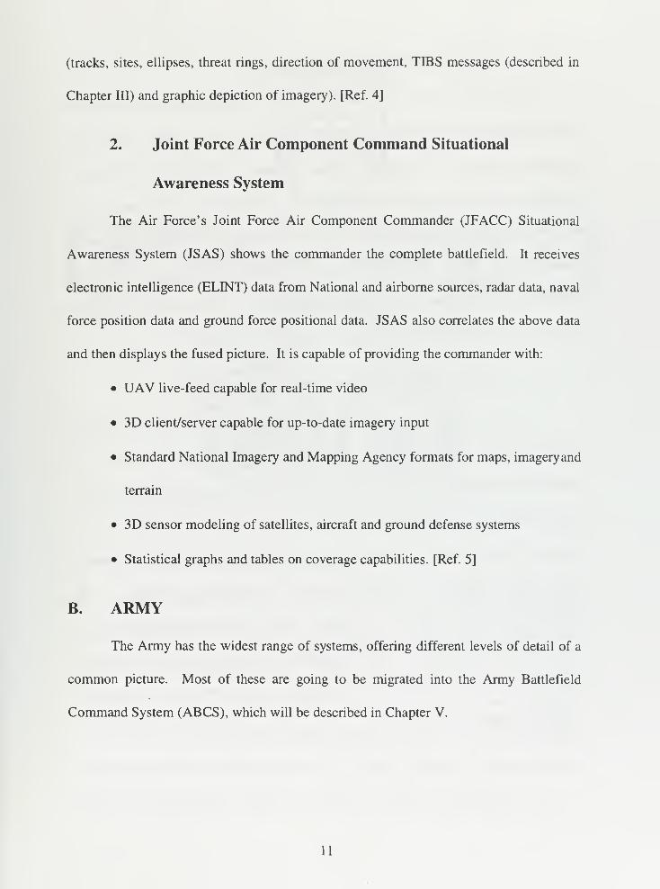
2. Joint Force Air Component Command Situational
Awareness System
The Air Force's Joint Force Air Component Commander (JFACC) Situational
Awareness System (JSAS) shows the commander the complete battlefield. It receives
electronic intelligence (ELINT) data from National and airborne sources, radar data, naval
force position data and ground force positional data. JSAS also correlates the above data
and then displays the fused picture. It is capable of providing the commander with:
• UAV live-feed capable for real-time video
• 3D client/server capable for up-to-date imagery input
• Standard National Imagery and Mapping Agency formats for maps, imageryand
terrain
• 3D sensor modeling of satellites, aircraft and ground defense systems
• Statistical graphs and tables on coverage capabilities. [Ref. 5]
B. ARMY
The Army has the widest range of systems, offering different levels of detail of a
common picture. Most of these are going to be migrated into the Army Battlefield
Command System (ABCS), which will be described in Chapter V.
11
1. Automated Digital Data System
The Automated Digital Data System (ADDS) is a collection of two automated
data distribution systems that give commanders a secure means to collect, manage and
disseminate near real-time locations of enemy and friendly positions and reconnaissance
and sensory information, as well as targeting data. The two systems that make up the
ADDS are the Joint Tactical Distribution Information System (JTIDS) and the Enhanced
Position Location Reporting System (EPLRS). EPLRS and JTIDS will be described in
Chapter HI. ADDS is one of three systems that comprise the Communications Hub for
the Army Tactical Command and Control System (ATCCS). [Ref. 6]
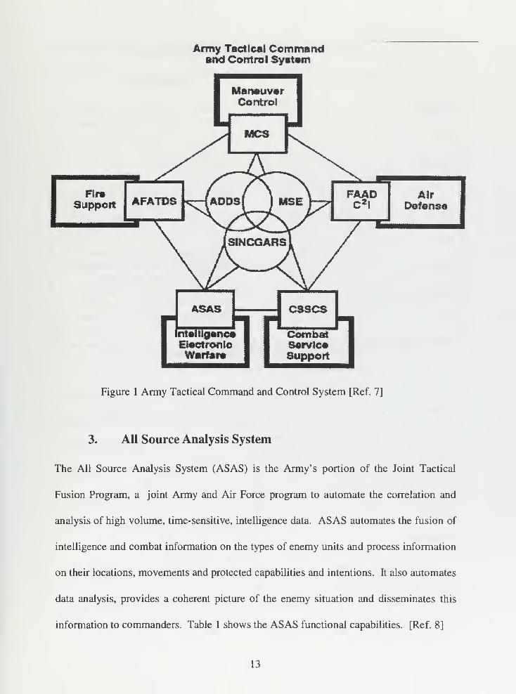
2. Army Tactical Command and Control System
The Army Tactical Command and Control System (ATCCS), part of the Army's
Enterprise Strategy, is a hierarchy of computerized control systems operating within five
Army Battlefield Functional Area Control Systems (BFACS) to process three categories
of information. The five BFACS include: fire support, intelligence and electronic warfare,
maneuver control (described in subsection 9 of this chapter), air defense and combat
service support (Figure 1). The three categories of information processed on the
battlefield are technical, staff and command. ATCCS processes data received from
sources across the battlefield. ATCCS redundant and common data base capabilities
permit the force level commander to operate from anywhere within his area of
responsibility. [Ref. 7]
12
Army Tactical Commandand Control System
[ManeuverControl
MCS
RraSupport AFATDS
•ar
AirDefense
ASAS esses
[ntelllgance CombatElectronic ServiceWarfare I | Support I
CombatSarvlcaSupport
Figure 1 Army Tactical Command and Control System [Ref. 7]
3. All Source Analysis System
The All Source Analysis System (ASAS) is the Army's portion of the Joint Tactical
Fusion Program, a joint Army and Air Force program to automate the correlation and
analysis of high volume, time-sensitive, intelligence data. ASAS automates the fusion of
intelligence and combat information on the types of enemy units and process information
on their locations, movements and protected capabilities and intentions. It also automates
data analysis, provides a coherent picture of the enemy situation and disseminates this
information to commanders. Table 1 shows the ASAS functional capabilities. [Ref. 8]
13
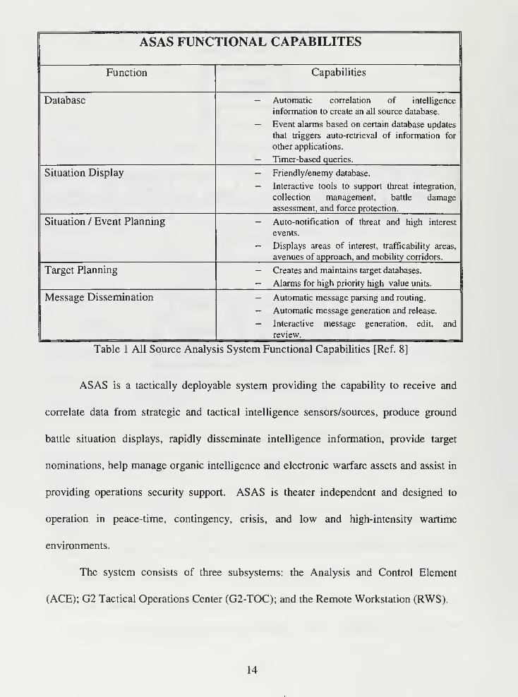
ASAS FUNCTIONAL CAPABILITES
Function Capabilities
Database — Automatic correlation of intelligence
information to create an all source database.
— Event alarms based on certain database updates
that triggers auto-retrieval of information for
other applications.
— Timer-based queries.
Situation Display — Friendly/enemy database.
— Interactive tools to support threat integration,
collection management, battle damage
assessment, and force protection.
Situation / Event Planning — Auto-notification of threat and high interest
events.
— Displays areas of interest, trafficability areas,
avenues of approach, and mobility corridors.
Target Planning — Creates and maintains target databases.
— Alarms for high priority high value units.
Message Dissemination — Automatic message parsing and routing.
— Automatic message generation and release.
— Interactive message generation, edit, and
review.
Table 1 All Source Analysis System Functional Capabilities [Ref. 8]
ASAS is a tactically deployable system providing the capability to receive and
correlate data from strategic and tactical intelligence sensors/sources, produce ground
battle situation displays, rapidly disseminate intelligence information, provide target
nominations, help manage organic intelligence and electronic warfare assets and assist in
providing operations security support. ASAS is theater independent and designed to
operation in peace-time, contingency, crisis, and low and high-intensity wartime
environments.
The system consists of three subsystems: the Analysis and Control Element
(ACE); G2 Tactical Operations Center (G2-TOC); and the Remote Workstation (RWS).
14
4. Forward Area Air Defense Command, Control and
Intelligence
The Army's FAAD C2I system is used to automate the command and control of
short-range air defense weapons. It supports the FAAD battalion mission by providing
C2 information to higher, adjacent, and lower units. FAAD C2I detects, identifies,
processes and instantly disseminates information on enemy and friendly aircraft to
forward area air defense units. It consists of four components: 1) the automated
command and control computer, 2) the ground based sensor, 3) an airborne sensor called
the masked target sensor and 4) an aircraft identification element. [Ref. 8]
FAAD C2I integrates air defense (AD) fire units, sensors and C2 centers into a
coherent system capable of defeating/denying the low altitude aerial threat (Unmanned
Aerial Vehicles (UAVs), helicopters, etc.). It provides the automated interface (corps and
below) for the AD control segments to the ABCS and allows commanders and staff to
communicate, plan, coordinate, direct and control the counter-air fight. The system
provides rapid collection, storage, processing, display and dissemination of critical, time-
sensitive situational awareness (air and ground) and battle command information
throughout the FAAD battalion and between other AD, Army, joint and combined
elements. FAAD C2I provides the third dimension situational awareness component of
the force level information (FLI) database. [Ref. 9]
The FAAD C2I system consists of processors, displays, software and
communications equipment to meet the C2 and targeting needs of FAAD battalions and
separate batteries. Computer displays allow commanders to access databases for the air
picture, situation reports, enemy assessments, friendly force status and maneuver control.
15
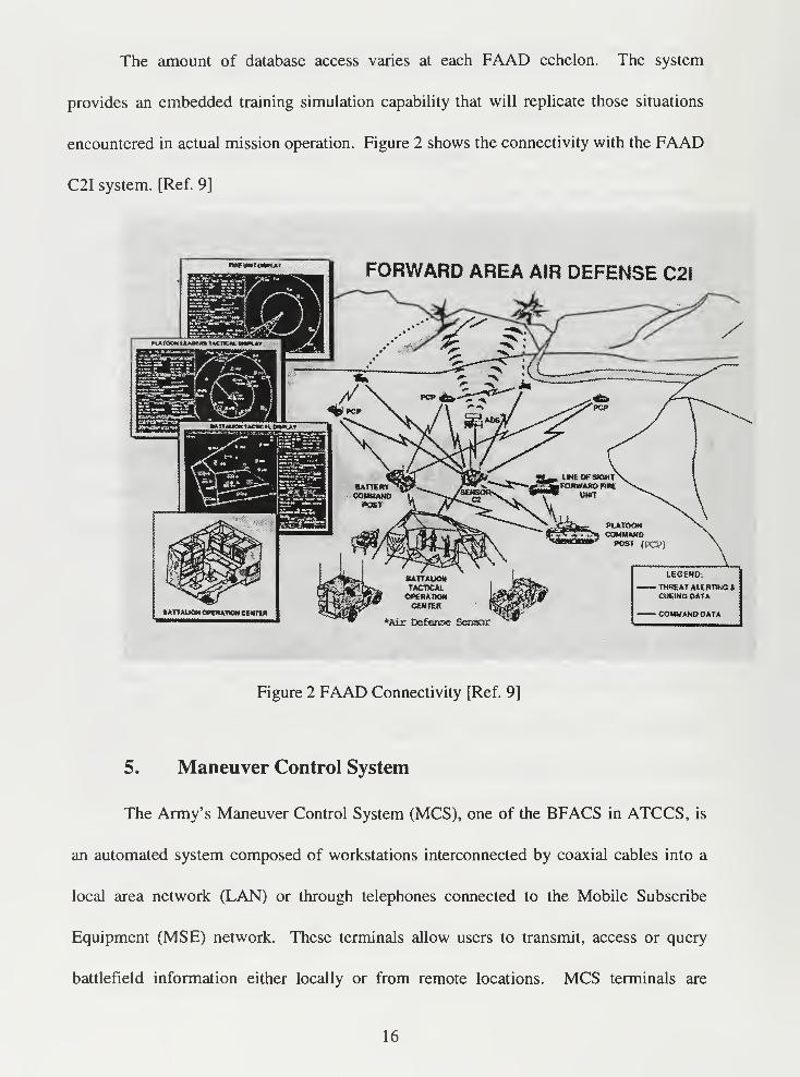
The amount of database access varies at each FAAD echelon. The system
provides an embedded training simulation capability that will replicate those situations
encountered in actual mission operation. Figure 2 shows the connectivity with the FAAD
C2I system. [Ref. 9]
mmtMROiMA* FORWARD AREA AIR DEFENSE C2I
ATTttKMOHOHTtM CEH Tin
Figure 2 FAAD Connectivity [Ref. 9]
5. Maneuver Control System
The Army's Maneuver Control System (MCS), one of the BFACS in ATCCS, is
an automated system composed of workstations interconnected by coaxial cables into a
local area network (LAN) or through telephones connected to the Mobile Subscribe
Equipment (MSE) network. These terminals allow users to transmit, access or query
battlefield information either locally or from remote locations. MCS terminals are
16
typically located in Tactical Operations Centers (TOCs) at the battalion through corps
levels. They support the exchange of near real-time tactical information such as friendly
and enemy positions. The system's graphical display provides commanders with an up-
to-date picture of the battlefield. [Ref. 10 and Ref. 1 1]
MCS displays and distributes critical tactical battlefield information for
commanders. Display capabilities provide commanders with decision support aids
including situation reports, intelligence reports, enemy contact reports assessing enemy
strength and movements and reports detailing status of friendly forces. These decision
supports aids can then be used to produce and distribute critical battlefield information.
Additionally, MCS can request intelligence, supply status, air operations and fire support
information from other BFACS. As part of the ATCCS, MCS uses the Communications
Hub to provide commanders at all levels with a common operational picture of the
battlefield that facilitates synchronization. [Ref. 12]
6. Standard Theater Army Command and Control System
The Standard Theater Army Command and Control System (STACCS) is a
theater level C4I system that provides users with accurate information on friendly and
hostile force activities. Users of this system are normally theater Army commanders and
staffs, Army component headquarters and major command levels. STACCS connects its
users' LANs to form a single Wide Area Network (WAN). The WAN gives commanders
the capability to readily access and exchange critical information needed to support
tactical decision making and order dissemination. This information generally includes
17
theater level communications status, staging area activities, force movement and resource
availability status.
STACCS uses common hardware components and a common software operating
system that supports an open system architecture which can be easily tailored to support
specific C2 functional requirements. Some of these functions are listed below.
• Graphics presentation
• Database management
• File management
• Message processing and control
• Common network management
• Gateway connectivity to other networks
The system is completely interoperable with the MCS used at Echelons Corps and
Below (ECB). This connectivity allows high level commander to acquire timely tactical
information needed to remain abreast of the tactical situation and exercise effective C2
over widely dispersed theater assets. The Army plans to standardize the STACCS basic
system architecture (excluding the tailoring of command unique functions) for use in
theaters world-wide. [Ref. 13]
C. JOINT
1. Joint Tactical Information Distribution System
The Joint Tactical Information Distribution System (JTIDS) is a high capacity,
high speed, spread spectrum information distribution system to provide Air Force, Army,
Navy and Marine Corps units with secure, jam resistant, low probability of exploitation
18
tactical data and voice communications. It provides precise Tactical Aids to Navigation
(TACAN), relative navigation and identification, and has additional capabilities for
common grid navigation. It also uses the automatic relay capability inherent in the long
range high frequency communications equipment. The system is interoperable among the
four services and NATO. It is the follow-on to the Naval Tactical Distribution System,
which is described in Section D of this Chapter. [Ref. 14]
D. NAVYAND MARINE CORPS
1. Joint Maritime Command Information System
The Joint Maritime Command Information System (JMCIS) is the primary C4I
system in the Navy. It assists both Naval flag and unit commanders in performing
mission data analysis requirements. JMCIS is an open client-server architecture that
consists of UNIX workstations connected to a LAN. The workstations allow users to
query a centralized database for specific information. The system supplies them with a
fused tactical picture of the battlespace, integrated intelligence processing services and
imagery exploitation capabilities. [Ref. 15]
JMICS is designed to eliminate specialized computer and unique software, and to
help adopt standard software and computer hardware in line with DoD policy. JMCIS is
an operational C2 system providing tactical C4I planning, execution and supervision
support for all warfare areas. It supports the C4I mission requirements of joint, Navy and
Marine Corps commanders, as well as facilitating information exchange with national,
joint and theater level commands. It also provides timely, accurate, and complete all-
source information management, display and dissemination capabilities. The core system
19
of JMCIS is the Unified Build (UB) software, which is the fundamental building block
for all Navy tactical C2 applications software. [Ref. 14]
2. Navy Tactical Data System
The Navy Tactical Data System (NTDS) is an automated combat direction system
developed in 1961 to address the anti-air warfare problem by automating the shipboard
combat information center (CIC). NTDS is presently aboard more than 200 active ships
in the fleet. The system is designed to display the overall tactical situation and pass
information by data link between participating units to present a shared real-time display
to support rapid decisions. NTDS processes tactical and selected intelligence data
received from onboard sensors, surface task force sensors and airborne sensors. NTDS is
supported by Link 11/ Tactical Digital Information Link (TADIL) A, Link 16 / TADIL J,
as well as intra-task force tactical voice and teletype circuits for related C2 functions.
The TADILs will be described in detail in Chapter III. [Ref. 7]
20
Ill THE GLOBAL COMMAND AND CONTROL SYSTEM
The preceding Chapter discussed current situational awareness systems available
to commanders. This Chapter discusses GCCS. First background is provided followed
by discussions on midterm fixes, DII, COE, COP, level of detail, reporting procedures,
track reporting and track fusion as they relate to GCCS and the warrior's COP.
A. C4I FOR THE WARRIOR
The Command, Control, Communications, Computers and Intelligence for the
Warrior (C4IFTW) concept developed by the Joint Staff provides the overall joint vision
necessary to focus the independent efforts of each service toward a series of common
objectives. The concept was introduced to address the difficulties that arose because
existing C4I resources provided insufficient interoperability. Many of these systems were
designed and developed to meet individual CINC and service organizational structures
and mission needs. These systems effectively support the stovepipe, hierarchical, vertical
military chain of command. However, they were not designed to support a fully
integrated joint force operation and are therefore limited when information requirements
are generated by horizontally integrated requirements. [Ref. 16]
The primary goal of the C4IFTW concept is to support the CINCs and CJTFs with
fused real-time information that provides a true picture of the battlespace. This
information not only provides warfighters with timely and relevant battlespace
information, but also enhances their ability to coordinate horizontally and vertically with
other organizations during the prosecution of the assigned missions. The concept acts as
a roadmap for integrating the warfighter' s critical functions into a common C4I system by
21
improving interoperability between the services, taking advantage of commercial-off-the-
shelf technology and providing maximum flexibility in joint force composition.
The three main components of the C4IFTW concept are the warrior's terminal, the
warrior's battlespace and the infosphere. The warrior's terminal is the composition of
hardware and software that gives the warrior multimedia connectivity and access to fused
battlespace information. These terminals perform a variety of functions to support the
warfighters specific C2 requirements including:
• Information storage and sharing
• Artificial intelligence and decision making tools
• Wargaming
• Simulation
• Multi-level security
• Tactical picture displays
• Interoperability and communication support [Ref. 1 and Ref. 17]
The warrior's battlespace refers to the area where the warrior exercises control or
military interest. Warriors, operating within their battlespace, require a fused tactical
picture that represents the integration of air, sea and land forces, opposing forces and
environmental factors which affect the battlespace. This dictates that information be
fused into a common operating environment that can be exchanged with other C4I
systems. By using approved standards, protocols and interfaces, interoperability between
existing systems is now possible.
The infosphere is a global C4I network that forms a seamless communication
architecture. It will provide the warfighter with immediate access to a central repository
22
of information at anytime and from anywhere. By having access to this information,
warriors can extract only the information needed to make timely decisions. Depending on
the commander's desires, the infosphere may automatically update the warrior's database
as the centralized database is changed or altered by sensors and other input systems. The
warfighter will be able to "pull" information, as needed, from the global infosphere and
be "pushed" or automatically provided selected information updates from consolidated
databases. [Ref. 6]
B. MIDTERM FIX
The World-Wide Military Command and Control System (WWMCCS), a
mainframe system based on 1970's technology, has long been the strategic C2 system.
During the 1980's, DoD undertook a large scale effort using classical acquisition
strategies to upgrade the existing system with new technologies. The approach proved
cumbersome, while warfighter needs still were increasingly unfulfilled.
In September 1992, the Under Secretary of Defense (Acquisition and Technology)
terminated the WWMCCS Automated Data Processing Modernization (WAM) Program.
He directed that a new acquisition approach be used to fulfill critical command and
control mission needs. The Assistant Secretary of Defense (C4I) subsequently
established GCCS as the principle migration path for defense-wide C2 systems. He also
directed that GCCS rapidly and efficiently deliver to combatant commanders C2
capabilities through maximum use of commercial off-the-shelf (COTS) and government
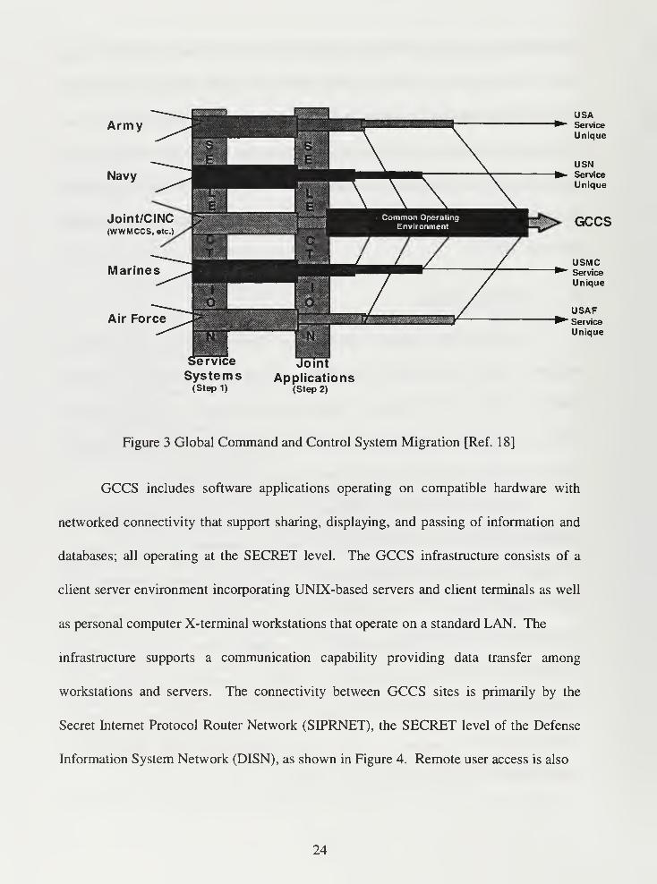
off-the-shelf (GOTS) components. GCCS is the midterm solution for the C4IFTW
concept. Figure 3 shows the steps leading to GCCS.
23
Army
Navy
Joint/CINC(WWMCCS, etc.)
Marines
Air Force
USAService
Unique
USNService
Unique
GCCS
USMC* Service
Unique
USAFService
Unique
service
Systems(Step 1)
Joint
Applications(Step 2)
Figure 3 Global Command and Control System Migration [Ref. 1 8]
GCCS includes software applications operating on compatible hardware with
networked connectivity that support sharing, displaying, and passing of information and
databases; all operating at the SECRET level. The GCCS infrastructure consists of a
client server environment incorporating UNIX-based servers and client terminals as well
as personal computer X-terminal workstations that operate on a standard LAN. The
infrastructure supports a communication capability providing data transfer among
workstations and servers. The connectivity between GCCS sites is primarily by the
Secret Internet Protocol Router Network (SIPRNET), the SECRET level of the Defense
Information System Network (DISN), as shown in Figure 4. Remote user access is also
24
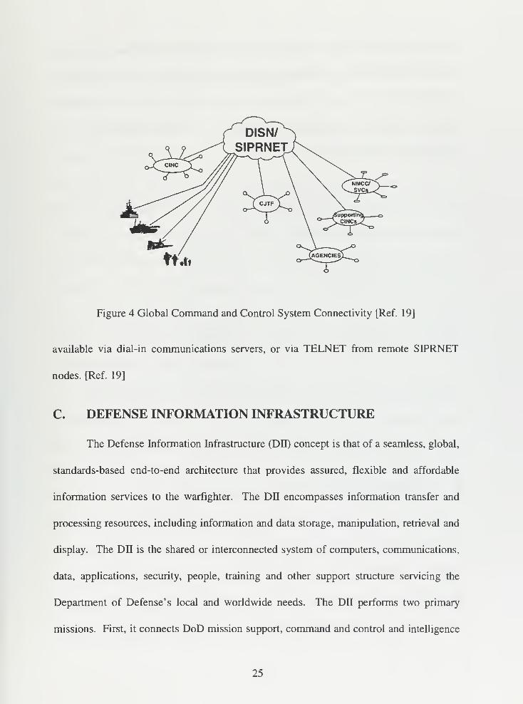
Figure 4 Global Command and Control System Connectivity [Ref. 19]
available via dial-in communications servers, or via TELNET from remote SIPRNET
nodes. [Ref. 19]
C. DEFENSE INFORMATION INFRASTRUCTURE
The Defense Information Infrastructure (DII) concept is that of a seamless, global,
standards-based end-to-end architecture that provides assured, flexible and affordable
information services to the warfighter. The DII encompasses information transfer and
processing resources, including information and data storage, manipulation, retrieval and
display. The DII is the shared or interconnected system of computers, communications,
data, applications, security, people, training and other support structure servicing the
Department of Defense's local and worldwide needs. The DII performs two primary
missions. First, it connects DoD mission support, command and control and intelligence
25
computers and users through voice, data, imagery, video and multimedia services; and
second, it also provides information processing and value-added services to subscribers
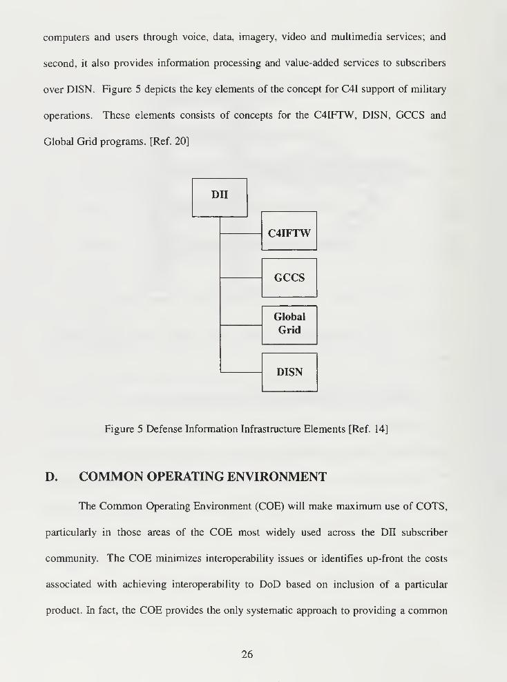
over DISN. Figure 5 depicts the key elements of the concept for C4I support of military
operations. These elements consists of concepts for the C4IFTW, DISN, GCCS and
Global Grid programs. [Ref. 20]
DII
C4IFTW
GCCS
Global
Grid
DISN
Figure 5 Defense Information Infrastructure Elements [Ref. 14]
D. COMMON OPERATING ENVIRONMENT
The Common Operating Environment (COE) will make maximum use of COTS,
particularly in those areas of the COE most widely used across the DII subscriber
community. The COE minimizes interoperability issues or identifies up-front the costs
associated with achieving interoperability to DoD based on inclusion of a particular
product. In fact, the COE provides the only systematic approach to providing a common
26
infrastructure across the DII on which system developers, engineers, and integrators can
confidently build with the goal of achieving system interoperability and the vision of
C4IFTW.
The COE is a collection of building blocks (segments) which form a software
"backplane". Segments "plug" into the COE just as circuit cards plug into a hardware
backplane. The blocks containing the operating system and windowing environment are
akin to a power supply as they contain the software which "powers" the rest of the
system. The segments labeled as COE component segments are equivalent to pre-built
boards such as the central processing unit (CPU) or memory cards. Some of them are
required (e.g., CPU) while others are optional (e.g., specialized communications interface
cards) depending upon how the system being built will be used. Mission application
segments are equivalent to adding custom circuit cards to the backplane to make the
system suitable for a more tailored purpose.
The COE is further defined in terms of a layered software architecture. Its present
definition consists of three layers driven by increasing levels of system interoperability as
one moves up the taxonomy (increasing the level of system compliance with the COE).
These layers are: the Kernel, Infrastructure Services, and Common Support Applications.
The Kernel is the minimum set of software required on every DII platform regardless of
how that platform will be used. The Kernel lays the basis for integration of the remainder
of the COE and is the first step in achieving system and component interoperability.
Infrastructure Services provide the low level tools necessary for data exchange.
These services provide the architectural framework for managing and distributing the
flow of data throughout a DH-based system and are, in general, COTS products.
27
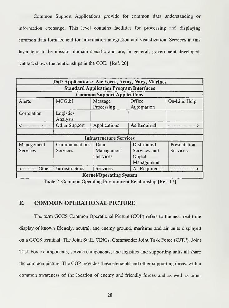
Common Support Applications provide for common data understanding or
information exchange. This level contains facilities for processing and displaying
common data formats, and for information integration and visualization. Services in this
layer tend to be mission domain specific and are, in general, government developed.
Table 2 shows the relationships in the COE. [Ref. 20]
DoD Applications: Air Force, Army, Navy, Marines
Standard Application Program Interfaces
Common Support Applications
Alerts MCG&I Message
Processing
Office
Automation
On-Line Help
Correlation Logistics
Analysis
Other Support Applications As Required *>^
Infrastructure Services
Management
Services
Communications
Services
Data
Management
Services
Distributed
Services and
Object
Management
Presentation
Services
< other Infrastructure Services As Required — >
Kernel/Operating System
Table 2 Common Operating Environment Relationship [Ref. 17]
E. COMMON OPERATIONAL PICTURE
The term GCCS Common Operational Picture (COP) refers to the near real time
display of known friendly, neutral, and enemy ground, maritime and air units displayed
on a GCCS terminal. The Joint Staff, CINCs, Commander Joint Task Force (CJTF), Joint
Task Force components, service components, and logistics and supporting units all share
the common picture. The COP provides these elements and other supporting forces with a
common awareness of the location of enemy and friendly forces and as well as other
28
relevant objects. It also provides information on environmental conditions within the area
of operations. The CINC can provide a broadcast of the COP to the Joint Staff as
required, and to forces outside the theater.
DISA selected the Navy's JMCIS, described in Chapter JJ, as the "best of breed"
to provide the common operational picture for GCCS. The COP uses a single relational
database structure common to all DJJ COE users; additionally, it is a kernel function of
GCCS. This common data baseline provides the afloat, ashore, and joint commanders
with a single, integrated C2 system that receives, processes, displays and maintains geo-
location information on all forces. It supports the warfighting commander's need for an
overarching operational picture. [Ref. 19]
The CINCs define, maintain and control the information in their AORs. Each
CINC will designate the build of the COP responsibility for each respective AOR.
Therefore, combatant commanders have overall responsibility for maintenance of the
COP within their theaters. They will determine the most appropriate arrangement for
distribution of the COP from a JTF or AOR to the Joint Staff and supporting commands.
In addition to ensuring the Chairman of the Joint Chiefs of Staff (CJCS) reporting
requirements are met, they may also specify additional theater requirements. [Ref. 16]
F. LEVEL OF DETAIL
The level of detail of the COP consists of two elements, information level and
force level. Information level refers to the hierarchy of COP information and consists of
the following categories: essential, necessary, additive, enhanced or extraneous. Force
level information refers to the reported force size that is reported in the following
29
categories: high interest tracks, major combat elements, major aviation units, SOF forces
and major forces.
The purpose of the reporting procedures (discussed in section G of this chapter) is
to build an accurate COP including the current representation of the battlespace or
Common Tactical Picture (CTP). The COP must be sufficiently complete to satisfy
commanders covering the whole spectrum from the NMCC to the CJTF. The system
must be flexible enough to allow for differences in organizational structures, situational
variances caused by the operation at hand, and different operating styles of each
commander. Hence, each commander has the responsibility to designate the appropriate
level of information and the force levels ensuring the COP accurately displays the current
situation. The fusion center (described in section I of this chapter) will play a key role in
providing the level of detail to build an accurate COP. Level of detail is situational
dependent. [Ref. 16]
The COP should become a standard reporting tool for the full spectrum of any
force engagement and at all levels of operations and war. Examples of operations include
conditions warranting the establishment of a Joint Task Force (JTF), crisis situations,
joint field exercises and normal daily operations. The levels of war include strategic,
operational and tactical. The COP must become an integral facet of the command and
control process. Therefore, use of the COP on a daily basis, as well as for JTF exercises is
necessary to ensure proficiency and continued development.
At each level of command, units must enter into their COP the data needed for
command and control. Commanders at each level must determine what those needs are.
Normally, the ground component will report information two echelons below the ground
30
component's headquarters. For example, if the ground component headquarters is an
Army Corps, then division and brigade formations should be displayed as separate icons.
Each command level will transmit data in accordance with their higher headquarters C2
needs. The higher headquarters is responsible for specifying what those needs are.
Subordinate units then send only the data that meets their higher headquarters needs.
Subordinate commanders should still send unrequested data to the higher commander for
the overall success of the mission. Hence, each commander has the responsibility to
designate the appropriate level of information and the force levels insuring the COP
accurately displays the current situation.
The CINC will determine what type of data the component and subordinate
commands must submit. As general guidance, the following data should be reported, as a
minimum:
1. Army and Marine Corps
(1) Unit Headquarters Brigade-level and higher.
(2) Base camp locations.
(3) Operational graphics showing Corps and Division boundaries.
(4) Locations from organic sensors of enemy, neutral and other organizations
2. Air Force
Since the majority of the data will enter the COP through TADIL B and TADIL J,
the level of detail will be down to the individual aircraft. The data will be transmitted by
the Airborne Warning and Control System (AWACS) aircraft Additionally, major
combat elements, by type, when not airborne should also be reported.
31
3. Navy
Ships report their location to the Battle Group Commander, who serves as the
Force Over-the-Horizon (OTH) Track Coordinator (FOTC). FOTC is the track fusion
center for the battle group. The FOTC has a JMCIS system that can correlate and add or
delete these track positions. Once correlated, the Officer in Tactical Command
Information System (OTCDCS) will broadcast the positions to the naval component
commander. The FOTC role is primarily to coordinate the maritime picture (to include all
know air, surface and subsurface contacts and address its accuracy. [Ref. 21]
G. REPORTING PROCEDURES
A basic principle of the COP is that CESfCs will task subordinate organizations as
data managers for different types of data information. Commanders will base these
taskings on the organization's areas of responsibility, their operational missions, and their
reporting capabilities. For example, the air, maritime and ground component commanders
will provide their respective component unit and/or track positions. Exceptions in
reporting, e.g., air tracks from the Navy, can occur depending on the nature of the
operation. These organizations are responsible for entering, updating and maintaining
their assigned tracks using existing automated or manual tools.
Reporting organizations will identify and enter tracks into the system through any
of three methods: 1) those detected by sensors and automatically reported, 2) those units
that automatically report their position and status or 3) those manually entered. Reporting
organizations also will perform track maintenance to remove redundant tracks by merging
32
existing tracks or units that are already in the data base. Each organization is responsible
for providing information to a designated COP integration site. [Ref. 21]
The information provided will either be a track or a force location. A track is any
force of any size within the AOR. An example of a track is a ship transiting through a
straight. A force is a track at a fixed location, either garrison, headquarters or operating
position of any component of any size. For example the headquarters of a wing, battalion
or a ship at port. The following 5 sections discuss each components responsibility in
reporting tracks to their commander.
1. Air Component
Air components report the daily location of major aviation units by type to the
commander when they are not airborne. They also report all known aircraft in the area of
interest that are part of the recognized air picture, as well as the location of major aviation
units by type when not airborne. This normally will be the garrison location of major
aviation units at the squadron level or above. Additionally, they report high interest
tracks (VTPs, special missions, special interest) operating within the normal area of
responsibility for the respective COP. Lastly, they report the location of major aviation
units within the AOR. [Ref. 16]
2. Ground Component
Ground components report only units that are in the area of interest. Ground
components will report the current location of all known ground units within their
battlespace. The positions should be updated when units move and as data becomes
available. Normally the ground component will report ground units two echelons below
33
the level of the Ground Component Commander. Organizations that must report ground
units to the CINC will report brigade-level and higher echelons. The ground component
may report units other than military forces if they feel the information is relevant to the
mission. Additionally, the component commander reports friendly, hostile, and neutral
ground units within the area of interest down to the major combat element size and
information level desired by the commander. Units report their current positions, and
update as they move. Ground components report major combat elements.
3. Naval Component
Naval components report the location of Battle Group and Amphibious Ready
Groups (ARGs) units. They also report other nations' ships when conducting out of area
operations or when appropriate. This is usually all contacts in the JMCIS database. The
naval components also report all known maritime tracks within the area of interest with
the proper level of detail desired by the commander.
4. Joint Special Operation Task Forces Commander
The Joint Special Operation Force (SOF) Commander (or Commander JSOTF)
provides location data (when classification permits) that details the location of SOF
forces when SOF forces operate within an AOR. When providing this information, the
SOF Commander is responsible for track management of SOF forces. The CINC may
also direct the JSOTF to report positions of SOF units down to team level whenever their
employment is of operational and strategic importance. Additionally, the CINC may
direct reporting of paramilitary units or units other than military forces if they are relevant
to the situation. [Ref. 21]
34
5. Special Interest Forces and Tracks
Special interest tracks and forces include tracks, regardless of size or composition,
of special importance that are key to an operation, linked to major negotiations, have
national level interest, and may involve the NCA. Examples of this include search and
rescue operations, humanitarian assistance forces, activities surrounding mishaps, travel
of VIPs, freedom of navigation operations and of forces in high interest peace keeping
operations. [Ref. 16]
H. TRACK REPORTING
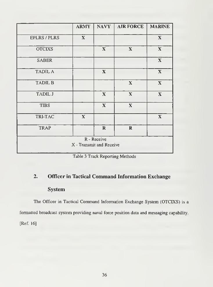
Tracks are received and transmitted using various means. Table 3 shows the
manner in which each service receives and transmits track data.
The tracks are reported to commanders using one of the following means:
1. Enhanced Position Location Reporting System
The Enhanced Position Location Reporting System (EPLRS) is a secure,
contention-free data communications system that tactical commanders and staff use to
report a unit's identification, location and navigation information. EPLRS supports the
exchange of real-time C2 information by using a geographically dispersed network of
secure Ultra High Frequency (UHF) radio relay links between net control stations and
user terminals. Although EPLRS was designed as an autonomous system, it can interface
with the Marine Corps' Position Location Reporting System (PLRS) and the Army's
Force XXI Battle Command Brigade and Below System (FBCB2), described in Chapter
IV. [Ref. 22]
35
ARMY NAVY AIR FORCE MARINE
EPLRS / PLRS X X
OTCIXS X X X
SABER X
TADIL A X X
TADILB X X
TADIL J X X X
TIBS X X
TRI-TAC X X
TRAP R R
R - Receive
X - Transmit and Receive
Table 3 Track Reporting Methods
2. Officer in Tactical Command Information Exchange
System
The Officer in Tactical Command Information Exchange System (OTCIXS) is a
formatted broadcast system providing naval force position data and messaging capability.
[Ref. 16]
36
3. Situational Awareness Beacon with Reply
Situation Awareness Beacon with Reply (SABER) is a leading edge technology
development that uses capabilities of space systems to help reduce battlefield fratricide.
Using a small transceiver, Global Positioning System (GPS) receiver and simple
packaging scheme, SABER enables a platform to report its position automatically
through UHF line of site or UHF SATCOM. [Ref. 23]
4. Tactical Digital Information Links
The Tactical Digital Information Links (TADILs) consist of a family of JCS
approved standardized communications links suitable for transmission of digital
information. TADILs are characterized by standardized message formats and
transmission characteristics. These standardized provide a readily acceptable
communications format for the cross-flow of information between services and allies.
a. TADILA/LINK11
TADIL A or Link 1 1 is a two-way, real-time, encrypted digital link that
utilized high frequency (HF) and UHF communications circuits, as well as shipboard
UHF satellite circuits. TADIL A primarily supports NTDS. TADIL A is operated in a
roll-call mode under control of a net control station, the information is exchange digitally
among airborne, land-based and shipboard systems.
37
b. TADILB
TADIL B is a point-to-point digital data link that connects land-based
tactical air defense and air control units. It is a secure, full-duplex digital link. This data
link interconnects tactical air defense and air control units.
c. TADIL J
TADIL J or Link 16 is a secure high capacity, jam-resistant, node-less data
link that uses the JTIDS transmission characteristics. Currently limited to UHF
transmissions (with an UHF relay capability), it provides extensive amplifying track data.
It provides real-time exchange of tactical digital information between major C2 systems
for the United States and NATO allies. This information will be used by ground, naval
and airborne units. JTIDS information is broadcast omnidirectionally at many thousands
of bits each second and can be received by any terminal within range. Information flows
directly from many transmitters to many receivers using a frequency-hopped, time-
sequenced transmission scheme. Each terminal, ground or airborne, can select or reject
each message according to its need. [Ref. 7]
5. Tactical Information Broadcast System
Tactical Information Broadcast System (TIBS) is a formatted satellite broadcast
system, delivering air and ELINT track data. TIBS air data will occasionally provide
amplifying track data like course, speed and altitude.
38
6. Tactical Related Applications
Tactical Related Applications (TRAP) is a formatted satellite broadcast system,
delivering a variety of nationally collected correlated data. [Ref. 16]
7. TRI-Service Tactical Communications System
The Tri-Service Tactical Communications System (TRI-TAC) is the Army, Air
Force and Marine Corps digital secure theater communications support system. It
provides connectivity and communications support to the corps Tactical Operations
Centers (TOC), major commands, Army component headquarters and JTF headquarters.
The network architecture is composed of a series of circuit and message switches
arranged in a grid-like pattern. Interconnectivity is achieved by using UHF or UHF
SATCOM. [Ref. 6 and Ref. 24]
I. TRACK FUSION
Track fusion is the process of receiving and integrating all-source, multiformat
information to produce and make available an accurate, complete and timely
comprehensive tactical picture of the disposition of all known surface, subsurface, air and
land based units. Track managers determined which reports go with what tracks during
the fusion process. Track managers for each component, air, land or sea have the
responsibility for management of their own particular types of track based on some
combination of AOR, attributes and sensors. The theater track manager conducts track
fusion for the COP for the CINC. The CINC then directs the dissemination of the fused
picture.
39
In the GCCS COP, track managers fuse contact reports from remote units into
tracks. The tracks may contain multiple contact reports from one or more distinctive
units. The track manager appends an identifying track number to each track update report.
This allows the updated track to associate with other contacts that are actually the same
track. This results in the fusion of contacts from remote sensors with contacts generated
by organic or dedicated sensors. As contact reports accumulate and the organization's
track manager correlates them into tracks, they become that organization's track data base.
This is the common operational picture held by all units of that organization. The fusion
center, the location where the above process is performed, will play a key role in
providing the level of detail sufficient to build an accurate COP. Level of detail will be
situational dependent. [Ref. 16]
Components are responsible for all source data correlation and fusion within their
reporting responsibility. They also have responsibility for ensuring the data is sent to the
GCCS COP using one of the means in Section F of this chapter. Only the component that
is responsible for reporting a track can manage that track. Track management requires
that only the reporting authority can delete the track, or merge it with another. The only
exception to this policy is the theater track manager, who may merge or delete any track
at any time. Data injection or track management from outside the AOR is not allowed
without the approval of the theater track manager. For example, a CINC can task the Joint
Intelligence Center (JIC) or Regional Signal Intelligence (SIGINT) Operations Center
(RSOC) to provide the CINC with correlated all source Intel data that could supplement,
modify or replace tracks being managed by a component. When done, the tasked unit
40
would then send the data to the responsible CINC component for integration into the
GCCS COP. [Ref. 19]
1. Joint Force Commander
The JFC becomes the primary track manager and fusion center for the COP upon
JTF establishment. The JFC is responsible for the COP within his Joint Operational Area
(JOA). This function may pass to either the CINC or to one of the JTF components
depending upon the geographic situation and communications availability. Additionally,
the JFC also ensures that all the component commanders are responsible for:
1
)
Fusion of organic and non-organic ground, naval and air track data prior to its
injection into the COP.
2) The deletion of tracks which have left the AOR, or are not valid.
2. Air Component Commander
The Air Component Commander (ACC) Track Manager is normally responsible
for reporting airborne contacts at altitudes from the surface up to 100,000 feet. A
Maritime Component Commander Track Manager may have to manage the air picture for
airborne contacts operating over water outside of the ACC's responsibility. The JFC will
correlate air tracks that have been reported by both component commanders.
3. Ground Component Commander
The Ground Component Commander (GCC) Track Manager is normally
responsible for reporting and data base management for all ground tracks at least two
echelons below its own command level, unless more detail is necessary.
41
4. Maritime Component Commander
The Maritime Component Commander (MCC) Track Manager is normally
responsible for reporting all maritime contacts. Depending upon the AOR and tactical
situation, the MCC will also manage the air picture for airborne tracks over water. [Ref.
21]
42
IV CURRENT EFFORTS
The previous chapters discussed current common operational picture systems
available to the commander and GCCS. This chapter will discuss current efforts of the
services to bring the COP to all levels of command.
Currently there is an over abundance of systems being developed to bring the
common operational picture to all levels of command. These emerging systems are not
fully integrated throughout the DoD, but initial delivery to the services has begun. While
all are DII COE compliant, none use the GCCS COP as the basis. The services are either
developing new systems or modifying or update current systems to bring the common
operational picture to lower levels of command. The following is a brief description of
the primary systems each service is developing.
A. AIR FORCE
On 17 Mar 95, the Air Force established the Air Force GCCS Program Office
(ESC/AVN) at Hanscom AFB to improve Air Force participation in the GCCS. Since its
creation, the office has become responsible for a small portion of COE development, has
created GCCS laboratories at Hanscom AFB and Gunter AFB, has participated in those
installation and testing efforts necessary to reach GCCS Initial Operational Capability
(IOC), and has begun to assist in the migration of Air Force systems to GCCS. However,
the Air Force has no current, detailed plan for increased GCCS involvement. Air Force
efforts are fragmented and underfunded. [Ref. 1 8]
The Air Force also does not have current efforts to bring the COP to lower levels
of command. While there are no new systems in development, they do have several
43
programs to bring JTIDS, described in Chapter II, to lower levels to include the cockpit of
fighters. They do however have some future efforts that will be discussed in Chapter V.
B. ARMY
Currently the Army does not have an integrated, automated, strategic to foxhole
C2 system. Commanders and staffs generally perform their mission using a manual
system, augmented by commercially available software systems. Current fielded
automation and communication systems do not provide the mobility, functional flexible
or interoperability required by the Army. These shortfalls hamper the ability to transport,
collect, disseminate and display information vertically and horizontally. The Army
Battlefield Command Systems, described in Chapter V, and the Army Global Command
and Control System, described in this Section, are being developed to overcome these
shortfalls. [Ref. 3]
The Army also currently lacks a fully functional integrated battle command
system for the mounted/dismounted leader at the brigade level and below. At maneuver
brigade and lower echelons, there is an inadequate capability to support information
needs of the commanders at each level because units are void of battle command digital
information devices and rely primarily on voice communications. Current
communications systems also do not provide sufficient data throughput for current and
emerging large capacity data terminals. This has impeded the ability to provide the
commander real-time and near real-time usable information on which to base tactical
decisions. [Ref. 25]
44
Additionally, the Army Tactical Command and Control System (described in
Chapter II), fielded in the Tactical Operations Center (TOC) at Brigades and Battalions
does not provide control functions such as sensor feeds that help reduce the risk of
fratricide, improve synchronization of fires, facilitate intelligence access, provide a near
real-time relevant common picture or increase force projection capabilities down to the
platform. The Force XXI Battle Command - Brigade and Below System, described in
this Section, is being developed to overcome this shortfall. [Ref. 25]
1. Army Global Command and Control System
The Army Global Command and Control System (AGCCS) is the Army link
between ABCS and GCCS. AGCCS will provide a suite of modular applications and
information and decision support-to Army strategic/operational/theater operations
planners. AGCCS will support the apportionment, allocation, logistical support and
deployment of Army forces to the combatant commands in response to planning and
policy guidance provided by the NCA during a crisis situation. Functionality includes
force tracking, host nation and civil affairs support, theater air defense, targeting,
psychological operations, C2, logistics, medical and personnel status. AGCCS will be
deployed from theater echelon above corps (EAC) elements down to the Corps where it
will link to the ATCCS. AGCCS includes STACCS, the Army Worldwide Military
Command and Control System Information System (AWIS), and the EAC portion of the
Combat Service Support Control System (CSSCS). [Ref. 3 and Ref. 6]
The migration of the legacy STACCS to the AGCCS will be a phased effort
which addresses several key technological improvements. The two immediate priorities
45
are to move from obsolete hardware, and to port to the Joint Standard Defense
Information Infrastructure Common Operating Environment. Further enhancements will
include the transition of STACCS applications to a single integrated data model, the
Army Global Database (AGDB); new technology insertion focusing on COTS software to
satisfy STACCS requirements; integration of theater and strategic functional applications;
expanded interfaces to include joint and future tactical systems; and, major improvements
to the data replication/distribution methodology. All these enhancements will be achieved
in an evolutionary manner through a number of AGCCS deliveries. [Ref. 1 1]
2. Force XXI Battle Command, Brigade and Below
The Army's Force XXI Battle Command, Brigade and Below System (FBCB2) is
a suite of digitally interoperable, battlefield operating systems (BOS) specific, functional
applications, designed to provide real-time and near real-time situational information to
tactical combat, combat support and combat service support leaders to the platform and
soldier level. FBCB2, as a key component of the ABCS, seamlessly interfaces with the
ATCCS, described in Chapter n, at brigade and battalion levels. It also supports C2
down to the soldier and platform level across all battlefield functional areas and echelons.
Figure 6 shows the interface between FBCB2 and other Army systems.
FBCB2 is going to provide the technology to complete the ABCS information
flow process from brigade to platform across all platforms within the brigade.
Additionally, FBCB2 will provide commanders the ability to remotely operate and
maintain ABCS database connectivity regardless of command vehicle, and to digitally
control and monitor their subordinate unit status and position. [Ref. 25]
46
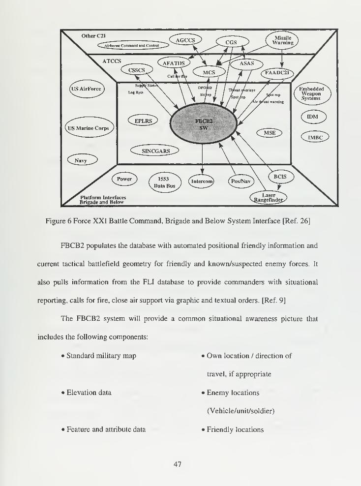
Figure 6 Force XXI Battle Command, Brigade and Below System Interface [Ref. 26]
FBCB2 populates the database with automated positional friendly information and
current tactical battlefield geometry for friendly and known/suspected enemy forces. It
also pulls information from the FLI database to provide commanders with situational
reporting, calls for fire, close air support via graphic and textual orders. [Ref. 9]
The FBCB2 system will provide a common situational awareness picture that
includes the following components:
Standard military map
• Elevation data
• Feature and attribute data
• Own location / direction of
travel, if appropriate
• Enemy locations
(Vehicle/unit/soldier)
• Friendly locations
47
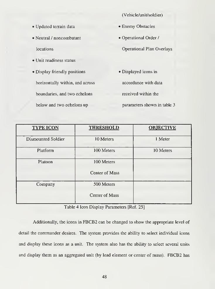
• Updated terrain data
• Neutral / noncombatant
locations
• Unit readiness status
• Display friendly positions
horizontally within, and across
boundaries, and two echelons
below and two echelons up
(Vehicle/unit/soldier)
• Enemy Obstacles
• Operational Order /
Operational Plan Overlays
• Displayed icons in
accordance with data
received within the
parameters shown in table 3
TYPE ICON THRESHOLD OBJECTIVE
Dismounted Soldier 10 Meters 1 Meter
Platform 100 Meters 10 Meters
Platoon 100 Meters
Center of Mass
Company 500 Meters
Center of Mass
Table 4 Icon Display Parameters [Ref. 25]
Additionally, the icons in FBCB2 can be changed to show the appropriate level of
detail the commander desires. The system provides the ability to select individual icons
and display these icons as a unit. The system also has the ability to select several units
and display them as an aggregated unit (by lead element or center of mass). FBCB2 has
48
the ability to decompose or deaggregate a displayed unit into smaller units or individual
system icons. This allows different levels to display the appropriate level of detail for the
commander and mission needs. [Ref. 25]
The display of the FBCB2 will be capable of the following:
• Displaying three dimensional representations.
• Displaying colors (e.g., standard military map colors).
• Provide a picture that is visible in all operating environments and light
conditions.
• Provide a picture that is visible from various angles as viewed by the operator.
• Provide a display with variable intensity and illumination that is adjustable by
the operator.
Additionally, FBCB2 will have the inherent capability to access information data
bases, in the push / pull mode described in Chapter HI. Information pulled from
databases will assist in planning and supporting military operations. FBCB2 will support
and interface with existing and emerging Army C4I systems to include ATCCS. The
transfer of battle command information will be automated over tactical data and voice
communication systems.
Lastly, FBCB2 is scheduled to have an Initial Operational Capabilities (IOC) on
or about FYOO. The IOC will be attained when FBCB2 is completely interoperable
within ABCS, fielded to the first combined arms maneuver brigade, fully trained (to
include supporting Combat Support and Combat Service Support elements) and judged to
be combat ready (to include required spares /repair parts, etc.). Full operational
49
capabilities will be attained when a corps set is fielded, proficient and considered combat
deployable using FBCB2 equipment. [Ref. 25]
C. MARINE CORPS
The Marine Corps is currently migrating all systems to the Navy JMICS.
However, there is one system that will be described in Chapter V that is meant to give the
tactical unit situational awareness that uses a DOS based program.
1. Marine Air Ground Task Force C4I
The Marine Air Ground Task Force C4I (MAGTF C4I) system, formerly the
Marine Tactical Automated Command and Control System, is the concept for integrating
communications and tactical data systems on the modern battlefield. The purpose of
MAGTF C4I is to provide Fleet Marine Force commanders with the means to manage the
complexity of the modern battlefield. MAGTF C4I will provide commanders and their
staffs with the capabilities to send, receive, process, filter and display data to aid in
tactical decision making. The MAGTF C4I software baseline relies on the COE resident
in the evolving GCCS DII COE established by the Defense Information Systems Agency.
The MAGTF C4I software baseline will be developed to ensure compatibility with the
GCCS DII COE as it continues to evolve from the foundations established by the initial
JMCIS-based versions. [Ref. 27]
The MAGTF C4I software is designed to support the information 'pull' concept
similar to the Navy's JMCIS. This concept allows Marine commanders to access only
information they need from a common database that receives periodic updates from many
different input sources. Interoperability between MAGTF systems and JMCIS databases
50
will make it possible for users in the Navy and Marine Corps to access, exchange and
update information between these systems.
As with JMCIS, the Marine Corps migration toward a single consolidated system
is driven by the Assistant Secretary of Defense C3I mandate directing all of the services
to eliminate their stovepipe and legacy systems to support data standardization. To fulfill
this objective, the Marine Corps plans to migrate their MAGTF C4I system first into
JMCIS and then later into GCCS. This required the Marine Corps to adopt common core
software modules provided by the Unified Build of the GCCS as well as ensure the
software is DII COE compliant. The core software provides an automated Command,
Control, Communications, Decision and Display System (C3DDS) capable of interfacing
across multiple communications circuits, processing standardized formatted messages,
and correlating contact reports to produce a consistent track database. Track data is
plotted on situation displays to create real-time tactical decision aides for both Marine and
Navy commanders. [Ref. 28]
2. Tactical Combat Operations System
The Tactical Combat Operations (TCO) System will be the focal point of the
MAGTF C4I network. It will provide the commanders, staffs and subordinates the
capability to receive, fuse, display, and disseminate C2 information, for both planning and
executing phases of an operation. The system will link the operations sections of all FMF
units of battalion or squadron size and larger. Marine forces embarked aboard Navy ships
will "plug in" to the JMCIS terminal. When ashore, the MAGTF C4I compliant system
will allow interoperability with joint forces over internal and external communications.
51
TCO will be located in Combat Service Support Operations Centers (CSSOC),
Operations Control and Analysis Center (OCAC), Combat Operations Centers (COC),
Tactical Air Command Centers (TACC) and Fire Direction Centers (FDC). [Ref. 10]
D. NAVY
Currently, the Navy already has situational awareness on most ships at the tactical
level due the JMCIS, described in Chapter EL There are however several other programs
that the Navy is currently developing. While these do bring a common picture to other
commands, it is a static not dynamic display. An example is the ELVIS processor.
ELVIS takes the GCCS COP and takes a snapshot picture that can be transmitted over
the SIPRNET. This allows units that do not have a COP but have the SEPRNET to have a
common picture for a specific set time period. As a consequence of the above, the
primary efforts of the Navy are to upgrade JMCIS and to develop a situational awareness
system for individual of the warfare areas (air, surface or subsurface). The following
section describes one of the systems that is being developed as a possible replacement for
the Naval Tactical Data System, described in Chapter U, for the Force Anti-Air Warfare
Commander.
1. Force Threat Evaluation and Weapons Assignment
The Force Threat Evaluation and Weapons Assignment (Force TEWA) system is
being developed by the Johns Hopkins University Applied Physics Laboratory to aid the
Force Anti-Air Warfare Coordinator in gaining situational awareness quicker than with
the Navy Tactical Data System. Using a powerful set of computers and a unique display
capability, Force TEWA takes the Link picture and displays it using sophisticated color
52
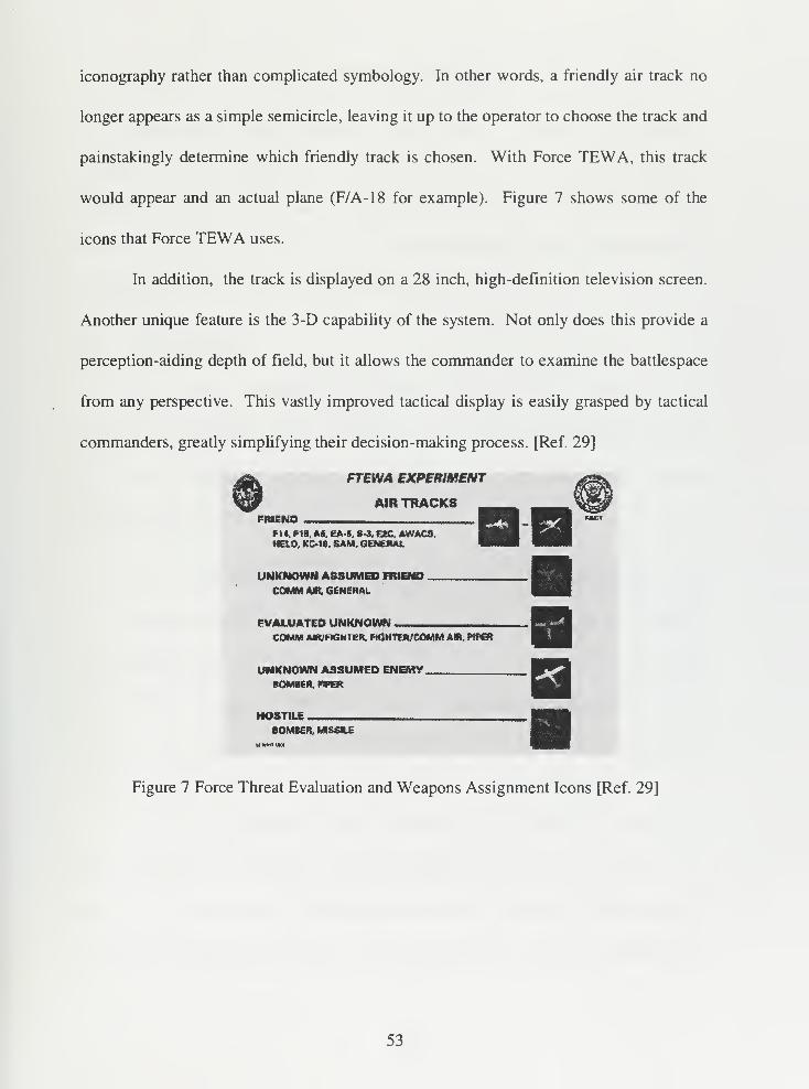
iconography rather than complicated symbology. In other words, a friendly air track no
longer appears as a simple semicircle, leaving it up to the operator to choose the track and
painstakingly determine which friendly track is chosen. With Force TEWA, this track
would appear and an actual plane (F/A-18 for example). Figure 7 shows some of the
icons that Force TEWA uses.
In addition, the track is displayed on a 28 inch, high-definition television screen.
Another unique feature is the 3-D capability of the system. Not only does this provide a
perception-aiding depth of field, but it allows the commander to examine the battlespace
from any perspective. This vastly improved tactical display is easily grasped by tactical
commanders, greatly simplifying their decision-making process. [Ref. 29]
FTEWA EXPERIMENT
AIR TRACKSFRIEND
f 14, FIB, AS, EA-6, S-3, E2C, AWACS,HEIO. KC18, SAM,GENERAL
UNKNOWN ASSUMED FRIEND .
COMM AIR. GENERAL
EVALUATED UNKNOWNCOMM AR/FNSHTEft, RCHTWCOMM AIR. PIP€R
UNKNOWN ASSUMED ENEMY.BOMBER. WER
HOSTILE
.
eOMKR,Mlfi«A£•J* Ml MM
Figure 7 Force Threat Evaluation and Weapons Assignment Icons [Ref. 29]
53

54
V FUTURE EFFORTS
The previous chapters discussed current common situational picture systems
available to the commander, GCCS and current efforts of the services to bring the COP to
all levels of command. This chapter will discuss future efforts of the services as well as
Defense Agencies. It also examines a Joint Staff study on future requirements for
commanders to have a common operational picture.
A. AIR FORCE
The Air Force initiated a new program in February 1997 to bring a common
picture to all levels of command. While this is currently in the initial stages, the final
product could provide a common operational picture to the lower levels which is
currently lacking today.
1. New World Vistas Global Awareness Virtual Testbed
The New World Vistas Global Awareness Virtual Testbed (NWV GAVTB) is
being driven by the Air Force vision of dominance in the information systems sector
called "Global Awareness" (GA). When fielded, it will include of a geographical display
of tracks and information from a centralized data base. Its motivation is the provision of
real-time situation awareness all any levels - strategic, operational and tactical.
GAVTB is envisioned to include tracks from multiple intelligence and tactical
data sources that are fused into a common operational picture of the battlefield. The
picture will use High Level Architecture protocols for the information dissemination to
allow for interoperability with other services. Additionally, it will have advanced real-
55
time data and information handling, retrieval and visualization techniques that will allow
a dynamic picture. The result will be a DII COE compliant system that will give the
commander a true real-time common operational picture using information provided by
multiple sources
The GAVTB research is also examining several different ways to aid the
commander with a common operational picture that will improve situational awareness.
These include a new GA architecture that allows commanders instant access to the
database that contains track information, regardless of where the database is physically
located. This can be seen as analogous to the tactical internet being developed for the
Battlefield Awareness and Data Dissemination Advanced Concept Technology
Demonstration, described later in this chapter. It also examines automated data and
information retrieval and indexing methods, automated data and information
dissemination for the sharing of the database information and new ways to fuse the multi-
sensor track information. Finally, GAVTB explores innovative presentation techniques
to give the commander the ability to gain situational awareness in a shorter time. [Ref.
30]
B. ARMY
1. Army Battlefield Command System
The goal of the Army Battlefield Command System (ABCS) is to provide a
seamless C2 capability from the strategic echelon to the foxhole and also be interoperable
with joint systems. It will be the tool commanders use to control the battlefield, project
situations, determine requirements and capabilities, develop courses of action and
56
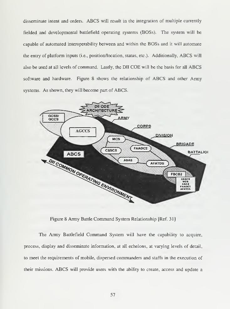
disseminate intent and orders. ABCS will result in the integration of multiple currently
fielded and developmental battlefield operating systems (BOSs). The system will be
capable of automated interoperability between and within the BOSs and it will automate
the entry of platform inputs (i.e., position/location, status, etc.). Additionally, ABCS will
also be used at all levels of command. Lastly, the DII COE will be the basis for all ABCS
software and hardware. Figure 8 shows the relationship of ABCS and other Army
systems. As shown, they will become part of ABCS.
BATTALIOI
Figure 8 Army Battle Command System Relationship [Ref. 3 1 ]
The Army Battlefield Command System will have the capability to acquire,
process, display and disseminate information, at all echelons, at varying levels of detail,
to meet the requirements of mobile, dispersed commanders and staffs in the execution of
their missions. ABCS will provide users with the ability to create, access and update a
57
FLI database and generate a user defined relevant, common picture of the battlefield in
both time and space. Data contained in the FLI database will be derived compliant with
DII COE, thereby ensuring interoperability with GCCS . In effect, the functional
difference between workstations will be determined by the set of functional applications
loaded on the machine.
The current developmental program of ABCS extend from the Joint/Strategic C4I
systems via the Army Global Command and Control System (AGCCS), described in
Chapter IV, through the theater of operations, to the operational/tactical headquarters, and
culminates in near real-time, digital links among the tactical battlefield operating systems
functions at brigade and below. [Ref. 3]
ABCS is made up of multiple C2 systems that operate from the strategic through
tactical level. There are three components within ABCS - AGCCS, ATCCS and FBCB2
C2 system for echelons brigade and below. The ABCS is tied to the joint environment
through GCCS. Each of the elements of the ABCS is further broken down into
subordinate systems. Figure 9 depicts all of these systems and their inter-relationships.
ABCS satisfies two critical C2 requirements: situational awareness - what has
come to be known as "the common picture" and interoperability. The common picture
refers to a predefined representation of battlefield information that is contained in the FLI
database. When this information is appropriately tailored in content and detail, it can
provide a commander a current view of the battlespace. The common picture in ABCS
may cross horizontal, vertical and functional boundaries. It is made up of three
components:
58
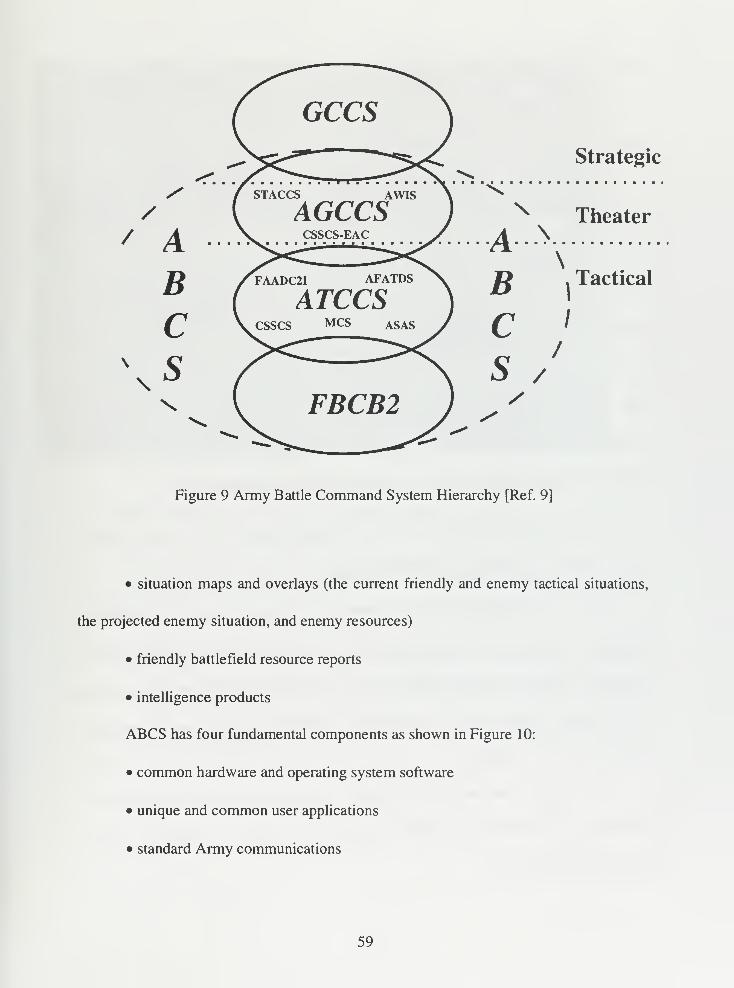
//
/ ABC
\,s
Strategic
Theater
\
Figure 9 Army Battle Command System Hierarchy [Ref. 9]
• situation maps and overlays (the current friendly and enemy tactical situations,
the projected enemy situation, and enemy resources)
• friendly battlefield resource reports
• intelligence products
ABCS has four fundamental components as shown in Figure 10:
• common hardware and operating system software
• unique and common user applications
• standard Army communications
59
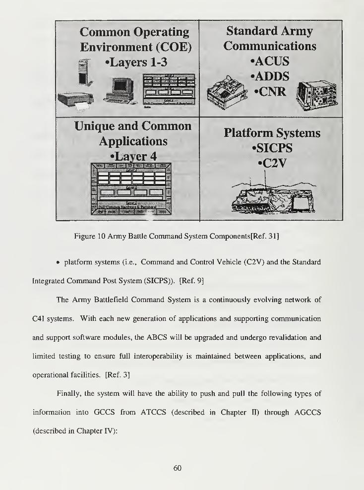
Common Operating
Environment (COE)•Layers 1-3
Standard ArmyCommunications
•ACUSADDS•CNR
Unique and CommonApplications
•Layer 4
Platform Systems
•SICPS
•C2V
Figure 10 Army Battle Command System Components[Ref. 311
• platform systems (i.e., Command and Control Vehicle (C2V) and the Standard
Integrated Command Post System (SICPS)). [Ref. 9]
The Army Battlefield Command System is a continuously evolving network of
C4I systems. With each new generation of applications and supporting communication
and support software modules, the ABCS will be upgraded and undergo revalidation and
limited testing to ensure full interoperability is maintained between applications, and
operational facilities. [Ref. 3]
Finally, the system will have the ability to push and pull the following types of
information into GCCS from ATCCS (described in Chapter II) through AGCCS
(described in Chapter IV):
60
• Maneuver Control System (MCS) (described in Chapter HI): Interfaces shall
provide a capability to exchange common picture data.
• All Source Analysis System (ASAS) (described in Chapter HI): Interfaces shall
provide a capability to exchange intelligence data with the Enemy Situation database.
• Forward Area Air Defense Command Control and Intelligence System (FAAD
C2) (described in Chapter HI): Interfaces shall provide the capability to exchange
Friendly/Enemy air track data.
• Combat Service Support Control System (CSSCS): Interfaces shall provide the
capability to exchange Combat Service Support data.
• Advanced Field Artillery Tactical Data System (AFATDS): Interfaces shall
provide the capability to exchange data pertaining to a call for fire and fire planning data.
The objective system shall provide 100% data exchange between FBCB2
(described in Chapter IV) and all of the ATCCS components. [Ref. 25]
C. DEFENSE ADVANCE RESEARCH PROJECT AGENCY
(DARPA)
DARPA is chartered to develop new technologies for the military. These new
technologies are to be used to aid each service in achieving Joint Vision 2010. One of the
projects currently being developed is the Battlefield Awareness and Data Dissemination
(BADD) Advanced Concept Technology Demonstration (ACTD).
61
1. Battlefield Awareness and Data Dissemination
The Battlefield Awareness and Data Dissemination (BADD) Advanced Concept
Technology Demonstration develops, installs and evaluates an operational system that
allows commanders to design their own information system; delivers to warfighters an
accurate, timely and consistent picture of the battlefield; and provides access to key
transmission mechanisms and worldwide data repositories. To achieve this goal, the
BADD system will:
• provide smart push and warrior pull via an Information Dissemination Server
(IDS) accessing multiple data sources to include national and theater intelligence,
operational and logistics information;
• use the data accessed to create a graphical depiction of the current situation
which is consistent across services and up and down echelon within each service and
which is linked to a variety of supporting information;
• allow the user to tailor the view of the battlespace by drilling down through the
supporting information infrastructure to display and manipulate the underlying data using
a BADD-provided tool kit compatible with the GCCS COE.
To achieve BADD's objectives, three system segments, each based on existing
products and prototypes, will be integrated: the communications management service, a
wideband, low-cost broadcast mechanism; the information management service, a means
for the warfighter to request specific information from the field using existing
communications; and the battlefield awareness service. Data accessed are from a wide
range of information sources including UAV and national imagery, GCCS operational
data, and fusion and exploitation sources, such as from the ASAS (described in Chapter
62
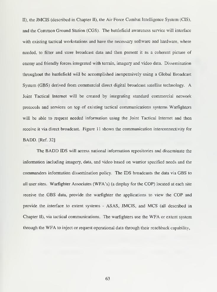
II), the JMCIS (described in Chapter H), the Air Force Combat Intelligence System (CIS),
and the Common Ground Station (CGS). The battlefield awareness service will interface
with existing tactical workstations and have the necessary software and hardware, where
needed, to filter and store broadcast data and then present it as a coherent picture of
enemy and friendly forces integrated with terrain, imagery and video data. Dissemination
throughout the battlefield will be accomplished inexpensively using a Global Broadcast
System (GBS) derived from commercial direct digital broadcast satellite technology. A
Joint Tactical Internet will be created by integrating standard commercial network
protocols and services on top of existing tactical communications systems Warfighters
will be able to request needed information using the Joint Tactical Internet and then
receive it via direct broadcast. Figure 1 1 shows the communication interconnectivity for
BADD. [Ref. 32]
The BADD IDS will access national information repositories and disseminate the
information including imagery, data, and video based on warrior specified needs and the
commanders information dissemination policy. The IDS broadcasts the data via GBS to
all user sites. Warfighter Associates (WFA's) (a display for the COP) located at each site
receive the GBS data, provide the warfighter the applications to view the COP and
provide the interface to extent systems - ASAS, JMCIS, and MCS (all described in
Chapter U), via tactical communications. The warfighters use the WFA or extent system
through the WFA to inject or request operational data through their reachback capability,
63
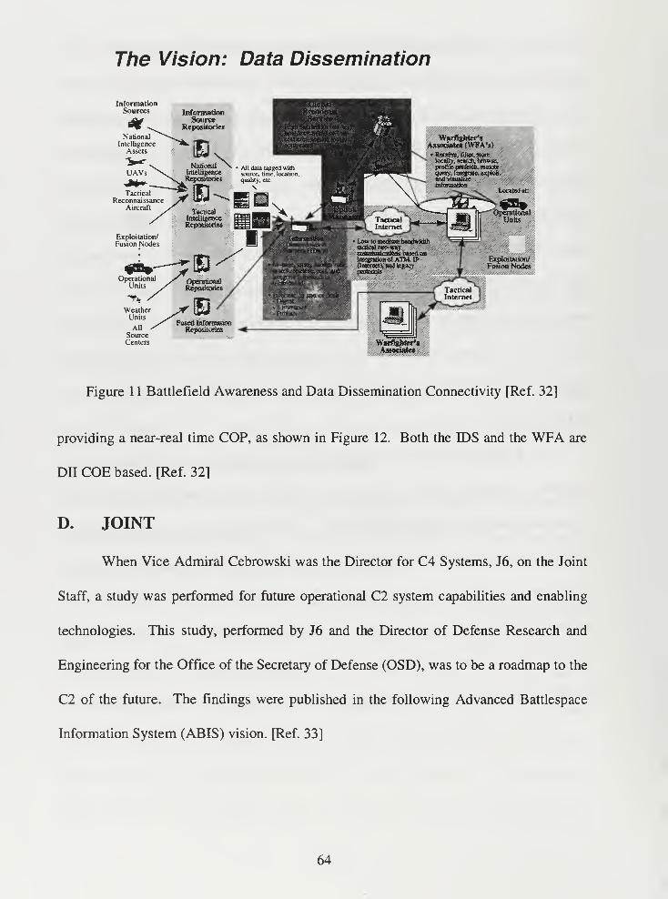
The Vision: Data Dissemination
InformationSources
Warfighter's
Associate* (WFA's).,.
" fcrowacprofile pietiM<*,Ktn<JKquery. Iaegr»t«, e*pk>Ii,
tnformaikratOCWK)«:
Figure 1 1 Battlefield Awareness and Data Dissemination Connectivity [Ref. 32]
providing a near-real time COP, as shown in Figure 12. Both the IDS and the WFA are
DH COE based. [Ref. 32]
D. JOINT
When Vice Admiral Cebrowski was the Director for C4 Systems, J6, on the Joint
Staff, a study was performed for future operational C2 system capabilities and enabling
technologies. This study, performed by J6 and the Director of Defense Research and
Engineering for the Office of the Secretary of Defense (OSD), was to be a roadmap to the
C2 of the future. The findings were published in the following Advanced Battlespace
Information System (ABIS) vision. [Ref. 33]
64
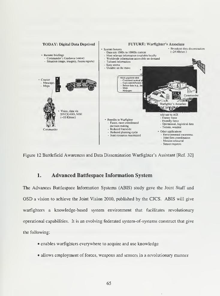
TODAY: Digital Data Deprived
Remote briefings
- Commander's Guidance (intent)
- Situation (maps, imagery, fusion reports)
Courier- Messages- Maps
• Voice, data via
SINCGARS, MSE(-10 Kb/sec)
Commander
FUTURE: Warfighter's Associate
System features
- Data rate lOOOx to lOOOOx current
- Most relevant information available locally
- Worldwide information accessible on demand- Tailored information
- Easy access
- Useable on the move
Broadcast data dissemination
(-24 Mb/sec.)
Muki-gigabvir disk
- Consistent tactical p- Exploitation/fusion
- Sensor data (e.g., 1ml
- Maps- Messages
Benefits to Warfighter
- Faster, more coordinated
decision making- Reduced fratricide
- Reduced planning cycle
- Joint resources maximized
relevant to AOI- Enemy force
- Friendly force
- Operational, logistical data
- Terrain, weather
Other applications
- Environmental awareness- Joint fires coordination
- Mission rehearsal
- Sensor requests
Figure 12 Battlefield Awareness and Data Dissemination Warfighter's Assistant [Ref. 32]
1. Advanced Battlespace Information System
The Advances Battlespace Information Systems (ABIS) study gave the Joint Staff and
OSD a vision to achieve the Joint Vision 2010, published by the CJCS. ABIS will give
warfighters a knowledge-based system environment that facilitates revolutionary
operational capabilities. It is an evolving federated system-of-systems construct that give
the following:
• enables warfighters everywhere to acquire and use knowledge
• allows employment of forces, weapons and sensors in a revolutionary manner
65
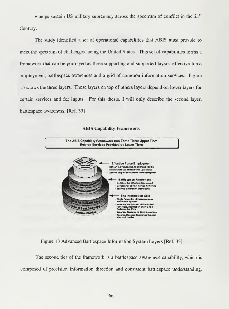
• helps sustain US military supremacy across the spectrum of conflict in the 21st
Century.
The study identified a set of operational capabilities that ABIS must provide to
meet the spectrum of challenges facing the United States. This set of capabilities forms a
framework that can be portrayed as three supporting and supported layers: effective force
employment, battlespace awareness and a grid of common information services. Figure
13 shows the three layers. Those layers on top of others layers depend on lower layers for
certain services and for inputs. For this thesis, I will only describe the second layer,
battlespace awareness. [Ref. 33]
ABIS Capability Framework
The ABIS Capability Framework Has Three Tiers: Upper Tiers
Rely on Services Provided by Lower Tiers
Effective Force EmploymentRehearse, Evaluate and Adapt Plana Rapidly
Sy nchronUe Distributed Fore* Operation*
Acquire Targets and Execute Timely Response
*«f— Battlespace Awareness• Collaborative Situation Assessment• Consistency of View Across All Force*
• Tailored Information Distribution
— The Information GridSingle Federation of HeterogeneousInformation Systems
Infrastructure Support of Distributed
Processes. Information Search, andCollaborative Work
Seamless Responsive Communications
Assured, Managed Resources SupportMission Prlorlttee
Figure 13 Advanced Battlespace Information System Layers [Ref. 33]
The second tier of the framework is a battlespace awareness capability, which is
composed of precision information direction and consistent battlespace understanding.
66
Precision information direction involves the ability to collect, process and channel
information to users in a timely and precise manner. It implies the ability of any
warfighter to tailor the environment to support the mission needs by directing where
different kinds of information can flow, when it flows and in what form it appears.
Information collection, processing and dissemination must by dynamically focused on
achieving the warfighter's specific mission objectives. Battlespace understanding
involves consistent and collaborative assessment of an operational situation and
objectives, including assessment of relevant support aspects. Assessors will typically be
distributed across multiple locations and will not need the raw information, but will need
information in the form conductive to the task as hand.
To achieve the battlespace awareness, the commander must have consistent
battlespace understanding. Consistent battlespace understanding includes all functions
involving the collection of relevant data and intelligence, the fusion of that information,
the incorporation of that information into a consistent, layered situation representation
and the cognitive presentation of that representation in a way that can be accessed and
assimilated by all warfighters at all levels. The principal elements of the future consistent
battlespace understanding concept are as follows:
• automated gathering of all relevant information from global databases, national
and theater sensor systems and friendly plans, force readiness and status
• merging this information into a consistent, layered representation for situation
assessment
67
• a cognitive, interactive presentation with varying degrees of aggregation, for
access and assimilation by warfighters but customized by them for the information that
they need.
This concept can also be viewed from the perspective that the warfighter is
provided rapid access to all the information that exists relevant to the needs, uninhibited
by the information systems itself. [Ref. 33]
E. MARINE CORPS
The Marine Corps is looking into combining two current systems into one system
to provide a common picture down beyond the battalion level. While the two systems are
currently fielded, the combination of the two is something that could inject information
into the GCCS COP.
1. Command and Control Personal Computer
The Command and Control Personal Computer (C2PC) is a version of the Navy's
JMCIS. It operates on commercial-off-the-shelf hardware. The application displays the
last reported position of friendly and reported enemy locations transmitted from a JMCIS
or GCCS terminal. The Marines are looking to combine this system with the Position
Location Reporting System (PLRS), described in Chapter UJ. The combination of the
two systems will provide a solution for projecting a common picture below the battalion
level. With the two system integrated, the C2PC will maintain an internal database of
PLRS and military identifications for each unit tracked to aid in correlation. [Ref. 34]
The combination will allow the extension of situational awareness below the
battalion level by integrating the robust PLRS network with numerous distributed PCs
68
The combination will allow the extension of situational awareness below the
battalion level by integrating the robust PLRS network with numerous distributed PCs
throughout the battlefield. These PCs would receive positioning updates directly from a
co-located basic user unit, and plot them as unit tracks directly within C2PC. With a
wireless single channel radio TCP/IP connection between the C2PC and the Tactical
Combat Operations (TCO) system, described in Chapter IV, the new system could
provide a robust means if injecting position location information (PLI) data into JMCIS.
Wireless TCP/IP also offers a way to pass overlays and other non-PLI unit tracks from
higher headquarters for simultaneous display on a PLRS-aware C2PC application. Figure
14 shows the C2PC connection. PLI data is thus injected in a bottom-up fashion from
subordinate units directly into the C2PC application as well as injected in a top-down
fashion from JMCIS. This will enable C2PC to become the command and control
application of choice for projecting a common picture to the small unit leader below the
battalion level. [Ref. 35]
F. NAVY
The Navy is taking an evolutionary approach to development of future systems. It
is updating JMCIS, described in Chapter U, from the UNIX based system to that of a
Microsoft Windows NT based system. The new JMCIS has been named both JMCIS 98
as well as GCCS-M, the Global Command and Control System - Maritime.
69
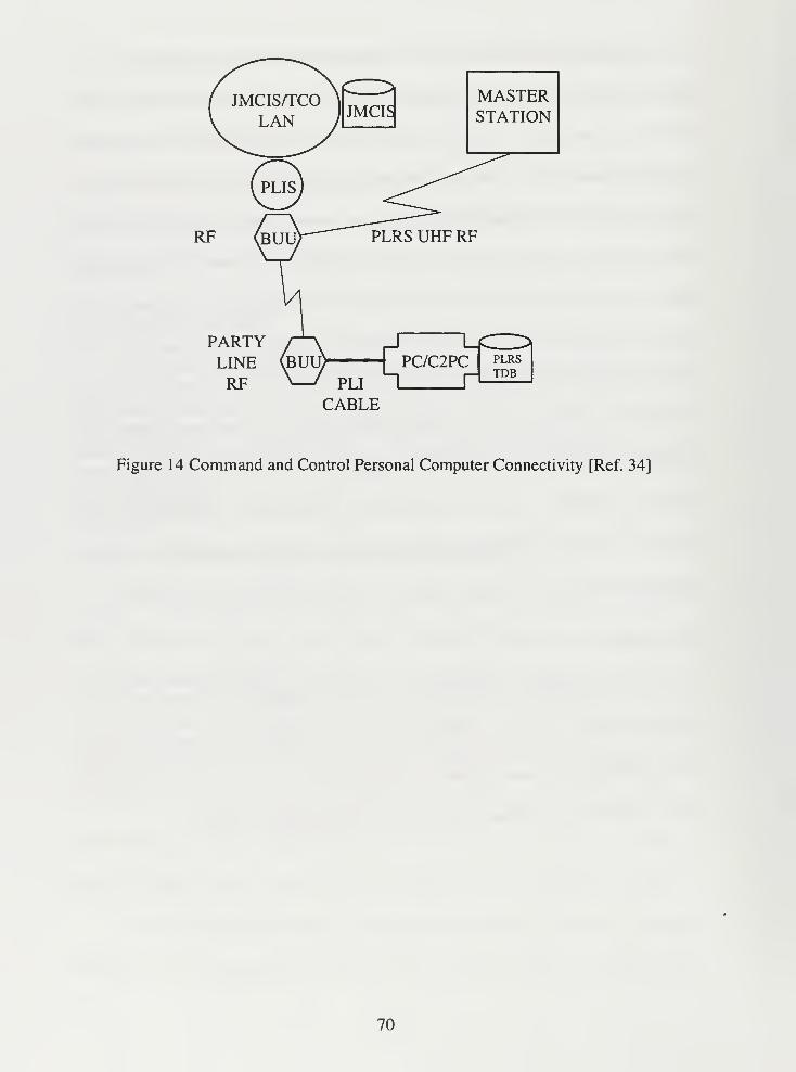
MASTERSTATION
PARTYLINERF
PC/C2PC
I PPLRSTDB
CABLE
Figure 14 Command and Control Personal Computer Connectivity [Ref. 34]
70
VI CONCLUSIONS AND RECOMMENDATIONS
The previous chapters discussed the need for a common operational picture at all
levels of command and the existing, planned and future efforts by each service and DoD
agencies to support the requirement. It also examines a Joint Staff study on future
requirements for commanders to have a common operational picture. This chapter
presents conclusions and gives recommendations to improve the common operational
picture.
A. CONCLUSION
This thesis gives a comprehensive review of the current situational awareness
systems available to commanders in addition to current and future efforts to bring a
common operational picture to all levels of command. With the decreasing budget,
corresponding push for the services to save money due to the decreasing budget and the
DoD's current focus on joint warfare, a system developed from the GCCS GOP for lower
levels of command would be logical. However, each service is either developing new
systems or revising current systems for use at lower levels. These systems are DU COE
compliant, but they are not interoperable beyond that. The services are still developing
stovepipe systems, but they are now DII COE compliant.
The databases that is being used by each service at every different level of
command is not centralized as it should be. Each service continues to use their own
display system and obtain / input track information into their own database. In some
cases, each level of command even maintains its own database. It is not until the CTNC
level that the databases are combined. This database is not sent down to the lower levels,
71
unless a direct communication link is established. It is however sent up to the national
level.
Admiral Cebrowski, the former Director of C4 Systems (J6) on the Joint Staff, has
stated that he made a tactical error concerning interoperability. He was under the
impression that each service would move toward joint systems rather than stovepipe ones
that are DII COE compliant. The services are ensuring that the systems are DII COE
compliant, but no one is ensuring that the systems are compatible. The systems discussed
in Chapters IV and V, Current and Future Efforts, state they are compatible with other
services, but the truth is in reality, they are just DII COE compatible. The systems are
interoperable only due to this degree of compatibility. [Ref. 36]
B. RECOMMENDATIONS
Each service is charged with training and equipping its forces. This is one of the
driving factors in the multitude of operational picture systems across the services today.
DISA developed GCCS as a national level system to replace WWMCCS. But, neither
DISA nor any other agency has the charter to develop a single system for the services or
to enforce the use of GCCS as a starting point in development of a service's common
operational picture.
I recommend that DISA be given the authority to force the services to develop
systems using GCCS DII COE as the basis for future COP systems. DISA is currently
only empowered to oversee that each new or modified system complies with the DII
COE. While this is important, it does not go far enough. Because the systems are only
required to be GCCS DII COE compliant but not interoperable, translators between
72
systems will be required for integrated interoperability between services at the operational
level.
The Joint Requirements Oversight Council (JROC) is charged with ensuring that
there is not duplication of effort, but one can see from Chapters IV and V that duplication
exists. Many system are being developed that accomplish the same function, bringing a
common but parochial operational picture to lower levels of command by service branch.
A Service Joint Program Office (JPO) for a common operational picture would
solve the problem of duplicate and redundant systems and I recommend that one be
established. But the services are hesitant to give authority to such an office. While I am
not advocating a "purple" (joint) C4I organization, the services need to cooperate and
develop basic core systems that each service will use, then develop service specific
applications (such as displays) from that core. This may sound like the DII COE, but it is
much more. It is similar to the Unified Build of JMCIS with each service having
different ways to display the same information. The efforts to bring a common picture
are commendable, but they need to be coordinated among the services, much like the
coordination between the Navy and Marine Corps.
The primary issue that must be overcome is the one of a centralized architecture
for the data contained within the database of each common operational picture. Each
different level of command still maintains its own distinct database as does each service
and CINC. While this should continue, the data contained within each database should be
accessible from all levels of command, both horizontally and vertically. The data should
be offered in a read only manner so each command's database is not corrupted. An
architecture needs to be established that ensures connectivity and interoperability between
73
vertical and horizontal commands. Until this database architecture is established and
maintained, commanders will not be able to get a true COMMON Operational Picture
among all services at all levels of command.
74
LIST OF REFERENCES
1. Joint Staff J6, C4I for the Warrior , C4 Architecture and Integration Division (J6I),
Pentagon, Washington, D.C., June 12 1993.
2. Department of the Navy, Copernicus . . . Forward.
3. Department of the Army, Capstone Requirements Document (CRD)
For the Army Battle Command System (ABCS), http://leav-www.army.mil/
tpioabcs/CRDA.htm, September 30, 1997.
4. Department of the Air Force, Air Combat Command Concept of Operations for
Theater Battle Management Core Systems, September 30, 1996.
5. Headquarters, U.S. Air Force, "JFACC Situational Awareness System information
phamplet," Received at Pentagon during October 1996 tour.
6. f. Office of the Assistant Secretary of Defense of C3I, Communications Handbook
for Intelligence Planners , INCA Project Office, March 1, 1991.
7. C4I Integration Support Activity, C4I Handbook for Integrated Planning (CHIP) ,
Defense Investigative Agency Publications, Washington, D.C., May 1996.
8. United States General Accounting Office, Battlefield Automation, Army Tactical
Command and Control System's Cost and Schedule . Washington, D.C. February,
1990.
9. Baribeau, Stephen R., Colonel, U.S. Army, Information Paper, The Army Battle
Command System (ABCS), July 30, 1996.
10. NRAD, "Command, Control, Communications, and Intelligence: System of
Systems," Information pamphlet, Command and Intelligence Systems Division,
San Diego, CA, 1993.
11. Bell, Carl H. in, Lieutenant Colonel, USAR, Theater Army Command and
Control System: An Evaluation of the Requirement and Proposed Solution . Study
project, U.S. Army War College, Carlisle Barracks, PA, May 1992.
12. Department of the Army, Maneuver Control System, Fact Sheet , Program
Executive Office, Command and Control Systems, Fort Monmouth, New Jersey,
1994.
13. Department of the Army, STACCS . http://www.stccs-
home.army.mil/wsdocs/stccs/staccs/staccs.htm, September 30, 1997.
75
14. Joint Staff J6, Joint Command, Control, Communications, and Computers
Systems Description Volume IL Washington, D.C., 1994.
15. International Research Institute, Joint Maritime Command Information System
(JMCIS) Common Operating Environment (COE) , Restion, VA, October 1, 1993.
16. Joint Staff J3, Chairman Joint Chief of Staff Instruction 3151.01, Global
Command and Control System Common Operational Picture Reporting
Requirements , April 1, 1997.
17. Joint Staff J6V, "Global Command and Control System," Washington, D.C.,
Received at DISA tour October 96.
18. Air Force GCCS System Program Office, Air Force Global Command and
Control System (GCCS) Migration Plan Guidance , August 8, 1996.
19. Joint Staff, Global Command and Control System User Concept of Operations .
Washington, D.C., December 1, 1995
20. Defense Information Systems Agency Instruction, COTS Inclusion in the DII
COE, April 1, 1997.
2 1
.
United States Central Command, Concept of Operations for Global Command and
Control System Common Operational Picture , October 22, 1996.
22. Hughes Corporation, "Enhanced Position Location Reporting System (EPLRS),"
Information sheet, May 1994.
23. Boyd, Autin, Commander, USN, "Rapid Response Through Space Reducing
Battlefield Fratricide," Surface Warfare Magazine , September/October, 1996.
24. Office of the Assistant Secretary of Defense for C3I, Communications Handbook
for Intelligence Planners . 3rd
Edition, INCA Project Office, 1994.
25. Department of the Army, Operational Requirements Document for Force XXIBattle Command - Bridage and Below (FBCB2) Version 5. May 30, 1997.
26. Army Digitization Office, Experimental Master Plan Force XXI Battle Command- Brigade and Below Applique . October 19, 1995.
27. Flynn, Bill, Lieutenant Commander, USN, "JMCIS Update, Empowering the
Warfighter," Surface Warfare Magazine. September/October 1995.
76
28. Kincaid, Gregory R., Captain, USAP, and Poligala, Richard A., Captain, USAF,
An Independent Evaluation of Information Systems Support of the Joint Forces
Air Component commander Concept of Operations , Master's Thesis, Air Force
Institute of Technology, Wright-Patterson, Ohio, February, 22, 1994.
29. Eyer, Kevin, Lieutenant Commander, USN, "FACT (Force TEWA)," Surface
Warfare Magazine , July/August 1995.
30. Goeringer, Michael L., 1st
Lieutenant, USAF, New World Vistas Global
Awareness Virtual Testbed Point Paper , August 19, 1997.
31. Army TRADOC Program Integration Office Army Battle Command System,
ABCS Briefing , July 30, 1997.
32. Defense Advanced Research Project Agency, Battlefield Awareness and Data
Dissemination Information Sheet , September 1997.
33. Department of Defense, Joint Staff, J6, Task Force, Advanced Battlespace
Information System (ABIS) Study.
34. Marine Corps Tactical Systems Support Activity, A PLRS AWARE C2PCProjecting Situational Awareness Below the Battalion Level January 22, 1997.
35. Cummiskey, James C, Major, USMC, Technical Report #2 on Position Location
Information (PLD and Small Unit Situational Awareness in Support of Kernal
Blitz 96 , January 21, 1997.
36. Interview with Vice Admiral Arthur K. Cebrowski, USN, December 9, 1996.
37. Defense Information System Agency Joint Interoperability and Engineering
Organization, Department of Defense Military Standard 2525 CommonWarfighting Symbology Implementation Concept August 2, 1994.
77

78
INITIAL DISTRIBUTION LIST
1. Defense Technical Information Center 2
8725 John J. Kingman Rd., Ste 0944
Ft. Belvoir, VA 22060-6218
2. Dudley Knox Library 2
Naval Postgraduate School
411 DyerRd.
Monterey, CA 93943-5101
3. C4I Academic Group, Code CC 1
Naval Postgraduate School
Monterey, CA 93943-5000
4. Professor Gary R. Porter, Code CC/PO 2
Naval Postgraduate School
Monterey, CA 93943-5000
5. Professor William G. Kemple, Code CC/KE 1
Naval Postgraduate School
Monterey, CA 93943-5000
6. Lieutenant Richard S. Hager 3
430 North Harbor Drive
Atlanta, GA 30328
7. Mr. Jon Stovall 1
465 1 River Court
Duluth, GA 30097
79


4 n 483NPG
10/99 22527-200