Embed Size (px)
Citation preview
NPS52-83-009
NAVAL POSTGRADUATE SCHOOL
Monterey, California
COMPUTER SYSTEM DESIGN ENVIRONMENT
SOFTWARE DEVELOPMENT PLAN
Ms. Jeanne Bowers
Lt.Col Alan A. Ross
July 1983
Approved for public release; distributed unlimited
Chief of Naval Research
Arlington, VA 22217
FedDocsD 208.14/2NPS-52-83-009
7 02. f4\2,'
-JTcX-S^-OQ6
] NAVAL POSTGRADUATE SCHOOLMonterey, California
Rear Admiral J. J. Ekelund D. A. SchradySuperintendent Provost
The work reported herein was supported in part by the FoundationResearch Program of the Naval Postgraduate School with funds providedby the Chief of Naval Research.
Reproduction of all or part of this report is authorized.
This report was prepared by:

UNCLASSIFIEDSECURITY CLASSIFICATION OF THIS PAGE (When Data Entered)
DUDLEY KNOX LIBRARYNAVAL POSTGRADUATE SCHOOLMONTEREY CA 9394
REPORT DOCUMENTATION PAGE READ INSTRUCTIONSBEFORE COMPLETING FORM
1. REPORT NUMBER
NPS52-83-009
2. GOVT ACCESSION NO 3. RECIPIENT'S CATALOG NUMBER
4. TITLE (and Subtitle) 5. TYPE OF REPORT • PERIOO COVERED
Computer System Design EnvironmentSoftware Development Plan
Technical Report
*. PERFORMING ORG. REPORT NUMBER
7. AUTHORC*;
Professor Alan A. Ross, Jeanne Bowers
8. CONTRACT OR GRANT NUMBERfaj
9. PERFORMING ORGANIZATION NAME AND ADDRESS
Naval Postgraduate School
Monterey, California 93943
10. PROGRAM ELEMENT. PROJECT. TASKAREA * WORK UNIT NUMBERS
61152N: RROOO-01-100N0001483WR30104
II. CONTROLLING OFFICE NAME AND ADDRESS
Chief of Naval ResearchArlington, VA 22217
12. REPORT DATEJuly 1983
IS. NUM2ER OF P*CES21
14. MONITORING AGENCY NAME a ADDRESSfJ/ dltterent from Controlling Otltce) IS. SECURITY CLASS, (ol thla report)
Unclassified
I5a. DECLASSIFICATION/ DOWNGRADINGSCHEDULE
16. DISTRIBUTION STATEMENT (ol thi. Report)
Approved for public release; distribution unlimited
17. DISTRIBUTION STATEMENT (ol the abatract entered In Block 20, U different irom Report)
18. SUPPLEMENTARY NOTES
19. KEY WORDS (Continue on reverte mldo If nacaeeary and Identity by block number)
primitivesuser-friendlydata baseprototype
computer aided designstructured developmenttranslatormapper
interrupt-driven monitorsyntax directed editordesign description language
20. ABSTRACT (Continue on reverme etde II neceeeery and Identity by block number)
The Computer Systems Design Environment (CSDE) project is an attempt at auto-
mated design of computer systems. The project develops a system which will
accept functional statements of requirements from the designer (utilizing a
user-friendly dialogue); translate those requirements into software and hard-
ware primitives; evaluate those primitives and develop a proposed system using
a Library of Realization Volumes. The CSDE will also verify that timing
requirements have been met by the proposed hardware and software; and present
DD fJAr73 1473 EDITION OF 1 NOV 6S IS OBSOLETE
S/N 0102- LF- 014- 6601UNCLASSIFIED
SECURITY CLASSIFICATION OF THIS PAOE (Whan Dalm tnlae—1)

UNCLASSIFIEDSECURITY CLASSIFICATION OF THIS PAGE (When Datm Enfrmd)
the systems design to the designer (in a user-friendly format). The CSDEwill be a prototype based on an existing feasibility demonstration versionwhich has verified the concept. The prototype version will explore issuesof adaptability, user friendliness and design system performance. Thispaper is a plan for the development of the CSDE.
S/N 0102- LF- 014-6601
UNCLASSIFIEDSECURITY CLASSIFICATION OF THIS PAGE(H?i»n Dmtm Enfr.d)
COMPUTER SYSTEM DESIGN ENVIRONMENTSOFTWARE DEVELOPMENT PLAN
July 29, 1983
I. Purpose of Plan
The purpose of this Software Development Plan is to describethe development approach for the Computer Systems DesignEnvironment (CSDE) , to schedule the development and imple-mentation, and to provide guidance to the researchers,staff and students involved in the project. The documentwill be used primarily in-house and, therefore, it is writ-ten to provide the project personnel with a direction forthe overall effort, guidelines for their individual tasks,and definition of how their thesis topic relates to theentire project. The document will require modification asthe project progresses, and will be updated once a quarterto reflect any required changes in direction or schedule.
II. Background
The basic concept for the CSDE was inspired by previousresearch conducted by M. N. Matelan on the design of realtime control systems. This CSDE concept has been developedby Professor Alan Ross and Professor Herschel Loomis at theNaval Postgraduate School. Currently, there is a function-ing model which was developed as a feasibility demonstrationand has confirmed that the concept is viable. The currentmodel is cumbersome to use and only provides the most basiccapabilities. However, it does generate a system design fora set of functional requirements based on a library of prim-itives.
III. Scope
The Computer System Design Environment is a set of tools forthe computer system designer. The CSDE will allow thedesigner to input the requirements of a problem in func-tional terms. The CSDE will examine the requirements andwill automatically generate a digital-processor based solu-tion to the problem. The design tools will apply the con-cepts of very high level languages, syntax directed editors,designer's workstations, scheduling theory, and hardware andsoftware descriptive languages to build libraries of problemsolution modules, and then to select among these modules todesign a particular system.
The Design Environment is modularized and, as shown in Fig-ure 1, there are five basic modules: the Input Translator,the Functional Mapper, the Timing Analyzer, the Library
-1-
Updater, and the Output Generator. The user of the systeminterfaces at three points with the modules: he inputsproblem descriptions into the Input Translator; he inputsdevice descriptions into the Library Updater; and hereceives the results on a display/graphics terminal orprinted report. The Library Updater module is an indepen-dent process which provides the Library of RealizationVolumes to the Functional Mapper and Timing Analyzer. Thefour other modules (excluding Library Updater) have a pro-cess and data flow from one to another as illustrated inFigure 1.
The objectives of the CSDE project are to develop a proto-type version of the system using applicable softwareengineering techniques and to enhance the functional capa-bilities of the feasibility demonstration version withimprovements and modifications developed while testing andusing it. The result of this effort will not be a produc-tion system; if the prototype is successful, a productionversion will be developed and implemented. The systemdeveloped will generate computer system designs for embeddeddigital computers within weapon systems. An attempt will bemade, as part of the project, to expand the concept to otherclasses of problems. The goal is to develop a single designsystem which will satisfy a maximum number of problems. TheCSDE system is a prototype and although accepted softwareengineering techniques will be used, the documentation willbe less complete than is required for a production system.Guidelines for the preparation of documentation are includedin Appendix A.
IV. General Approach to Development
The systems development approach to be used in this effortis based on a systems design methodology, structured pro-gramming, and the Oracle data base development tools.Structured walkthroughs will be conducted by the thesis stu-dent for the project personnel throughout the developmentcycle. All documentation will be done using an automatedtext editor. The following sections will describe the gen-eral development steps, the hardware and software environ-ment, and the relationships among the participants of theproject.
A. Development Steps
The following paragraphs describe the general steps to beused for developing software for the project:
o Plan development - This step includes a detailed analysisof the tasks that need to be done and the time frames
-2-

UJ U-l \or OS \~c <co \Sfe *— \Q"«»t— 5£OS L±- —1 \«*: <=> \zxz CO \
7T Q_
CD
oCO
»— u_COCO
c_>
-3-
required based on the level of participation. Duringthis step, a Milestone Chart will be developed which willbe revised as the project evolves. These milestones willbe established using the Development Steps listed belowas a guideline. The time frame estimate in this SoftwareDevelopment Plan for the overall task or subtask shouldalso be considered. If necessary, the individual mile-stone charts will dictate a change to this SoftwareDevelopment Plan.
o Define/verify detailed requirements - This step includesa detailed definition of what the specific module of theCSDE should be capable of doing. The process to be usedto define these requirements consists of the following:a functional analysis of the module including a decompo-sition and a concise description for each subfunction; adefinition of the data categories required to support thefunction; a description of the relationship between thesubfunctions and the data; an identification of the tran-sactions required to drive the module; and a structurefor the data base including the required categories andtheir relationships. During this step, the RequirementsDocument will be produced (See Appendix A for guidelineson the contents and structure of the Requirements Docu-ment) .
o Evaluate existing module to determine task approach -
This step includes analyzing the existing program moduleand determining how to proceed. The existing module mustbe functionally analyzed to determine how many of therequired functions are currently included in the feasi-bility version. The data currently generated and/or usedby the existing module must be examined and compared withwhat is required of the module which is being developed.The results of this step will be used to determine whichsucceeding steps will be done and to what degree theymust be done. A synopsis of the findings of this stepand the conclusions concerning the subsequent stepsshould be prepared.
o Design new module or enhancement to current module - Thisstep includes the design of the detailed logic of theprograms or modifications necessary to meet the require-ments previously defined. The output from this stepwill be program specifications and/or modificationspecifications (See Appendix A for guidelines in prepar-ing program and program modification specifications).All logic developed for the CSDE will use a structuredapproach
.
o Code and test new module or enhancement - This stepincludes the actual programming, testing and debugging ofthe computer software. The language which will be used
-4-

for programming will be determined by the primaryresearcher; the language will be compatible with the Ora-cle Data Base Management System. Programming will usestructured techniques and development and testing of pro-grams will be, as much as practical, top-down. Testingwill be done at a program level first and then at a com-bined level with the other programs with which the pro-gram interfaces. An informal test plan will be developedbefore testing begins. Test data and results will beretained for documentation. The programs should be wellcommented and readable using good indentation techniques.The documentation from this step will be an updated andamplified (where applicable) specification with theattachment of appropriate test data and results (SeeAppendix A for guidelines in producing maintenance docu-mentation) .
Document new module or enhancement - Since we havepreviously discussed documentation at the specificationand maintenance level, this step includes only user docu-mentation. User "help" screens are strongly encouraged,but a small user document is required to supplement theonline documentation for procedures such as initiallygetting on the system (See Appendix A for guidelines inproducing user documentation)
.
Perform final testing and integrationThis step includes the interfacing ofthe currently existing CSDE. The i
ments should be verified to ensurechanged since the original requiremenAn outline of the steps necessary to i
should be prepared and scheduledresearcher. This step is a critical ocan very easily cause serious problcommunication and planning are the key
into the system -
the new module withnterfacing require-that nothing has
ts were identified,ntegrate the modulewith the primary
ne and one whichems. Coordination,to success.
If, during the course of any of these development steps, thethesis student determines either the need for splitting histopic or for adding an additional topic, he should informhis thesis advisor who should forward the information to theprimary researcher immediately.
B. Environment - The following paragraphs describe thehardware and software environments in which the CSDE will bedeveloped
.
1. Hardware - The development work will beusing a Digital Equipment Corporation VAXWorkstations or equivalents will be procureddesigner workstations. As many high-level tools as possiblewill be implemented for the designer at the
accompl ished11-780. VAXto act as
workstation to
-5-

make his function easier.
2. Software - The Digital Equipment Corporation VAX VMSOperating System will be used as the operating softwareenvironment. In addition, the Oracle Data Base ManagementSystem and its design aids will be used where applicable.The EDT editor will be used for documentation and programediting. The specific language compiler/interpreter will bedetermined by the primary researcher.
C. Staffing - The following paragraphs describe the respon-sibilities of each category of the project staff. Eachthesis study will be conducted by a thesis student with gui-dance from a thesis advisor and assistance from the ComputerScience Department staff.
1. Researchers - The primary researcher is LTCOL Alan Ross;he will be assisted by associate researchers Professor Her-schel Loomis, Professor George Rahe, and Captain BradfordMercer. The responsibility of the primary researcher is oneof planning, control and coordination. He must keep theoverall project progressing and must assure that the piecesfit together at the appropriate times. He will administerthe project but will do so from a very technical point ofview. The reports which must be produced for sponsors ofthe research will be prepared by the primary researcher withhelp from his associates. Each associate researcher has oneor more area(s) of specific interest and will be involved inthe researching and development of those areas. The specificareas of interest for the associate researchers are: Pro-fessor Loomis, timing analysis and the implementation of theRealization Library; Professor Rahe, man-machine interface;and Captain Mercer, representations and methods for describ-ing systems and primitives. All researchers will act asthesis student advisors.
2. Students - The students associated with the project willbe thesis students developing one aspect of the CSDE astheir thesis topic. Due to the significant turnover in thestudents participating in the project, a project staff per-son will be peripherally involved in all thesis work. Anofficial turnover of programs and supporting documentationto the project staff person will be required of each studentprior to his or her departure. The students can requestassistance from the project staff and the Computer ScienceDepartment staff, as required.
3. Staff Support - The support available to the projectincludes both project and Computer Science Department Staff.The project staff includes one full-time Programmer/Analyst,one part-time Technician/Data Entry, and a small amount ofclerical support. The Computer Science Department staff
•6-
members will not be dedicated to the project, but will beavailable to assist the project staff, students andresearchers, as required, specifically in areas such as theuse of the development methodology, VMS and ORACLE.
V. Assumptions
The following is a list of items which are assumed to betrue for the development process.
o Funding will be available for staffing in accordance withthe Computer System Design Environment Project Proposaldated May 23,1983.
o The Oracle Data Base Management System will be availablefor use by the project.
o Support will be available from the Computer ScienceDepartment Staff in the areas of the system design metho-dology being used, VMS and ORACLE.
VI. Detailed Plan
Section III identified five modules which make up the CSDE.These five modules and two additional areas are nowaddressed in greater detail.
A. Functional Breakdown
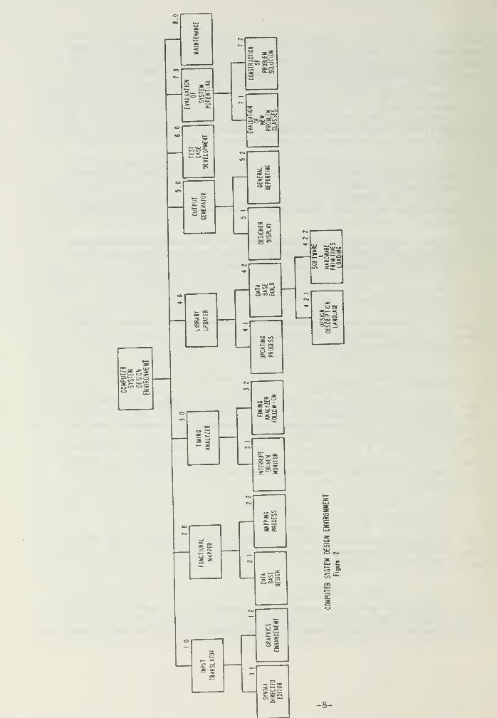
The process of systems development will include decomposingthe system into its smallest functional pieces. In order toadequately plan the development and identify thesis topics,the initial steps of this decomposition must be accom-plished. Figure 2 illustrates the results of this processdown to the specific tasks and subtasks. Additional decom-position will be done during the analysis phase of thedevelopment.
B. Description of Functions
The following paragraphs will describe the tasks and sub-tasks of the project and will indicate which of these willbe separate thesis topics.
1. Task 1 - Input Translator
The major goal of this task is to produce a user-friendlyenvironment which will allow the designer to input therequirements of his system using a functional approach and
•7-
o
CO§3
;w«
gg
CO <•>
s
?tt!
»*"»
-5g
«
INTERRUPT DRIVEN MONITOR
5 2:
<J> 3KUJ
cu
-8-
an easily understandable language. The task has been dividedinto two subtasks with each representing a potential thesistopic.
a. Subtask 1.1 - Syntax Directed Editor
This subtask includes the overall analysis of the require-ments of the Input Translator and the completion of thedevelopment of a syntax directed editor. The current thesiswork of LCDR Barbara Sherlock will be the basis for thissubtask
.
b. Subtask 1.2 - Graphics Enhancement
This subtask includes the analysis and evaluation of the useof graphical techniques for inputting system requirements.The subtask determines if graphics can be feasibly inter-faced, and, if so, accomplishes the interface.
2. Task 2 - Functional Mapper
The major goal of this task is to produce an environment fora simpler and more efficient mapping of requirements toavailable components. The task has been divided into twosubtasks with each representing a potential thesis topic.
a. Subtask 2.1 - Data Base Design
This subtask includes the overall design of the entire database for the CSDE. This data base design will include botha logical and physical design (based on Oracle as the database management system). The approach will be to do theentire design as a separate subtask and thesis projectrather than to split the data base design according to thefunctions that the data support. This approach will provideconsistency of design and coordination of commonly useddata. The design will be susceptible to modification asdetailed development of other tasks is undertaken. Sincethe ability to respond easily to requirements modificationis a strength of data base management systems, this approachwas selected. Once this subtask is complete, it is impor-tant that a Data Administration function be established toassure continuity, consistency and coordination.
b. Subtask 2.2 - Mapping Process
This subtask includes the overall analysis of the require-ments of the functional mapping process and the satisfactionof those requirements in a data base environment using theOracle Data Base Management System. The data base designwill not be a part of this topic, but the implementation ofthat design for the tables used by the Mapping Process andnot previously implemented by another task will be included.
-9-

3. Task 3 - Timing Analyzer
The major goal of this task is to produce a monitor whichwill efficiently analyze and evaluate the timing require-ments of the problem, and compare them with the speed of thesystem generated in the Functional Mapper. The task hasbeen divided into two subtasks with each representing a
potential thesis topic.
a. Subtask 3.1 - Interrupt-Dr iven Monitor
This subtask includes the overall analysis of the require-ments of the Timing Analyzer and the development of anInterrupt-Dr iven Monitor strategy which will satisfy thoserequirements
.
b. Subtask 3.2 - Timing Analyzer Follow-on
This subtask is not clearly defined at this point. It islisted because it is believed that following the interrupt-driven approach to the monitor, further work will berequired to refine the approach or develop a new one.
4. Task 4 - Library Updater
The major goal of this task is to achieve a Library of Real-izations with both hardware and software primitives loadedinto the database using hardware and software designlanguages. The task has been divided into two subtasks.The first subtask represents a potential thesis topic; thesecond breaks down further into two additional subtasks witheach representing a potential thesis topic.
a. Subtask 4.1 - Updating Process
This subtask includes the implementation of the library por-tion of the previously designed data base and the develop-ment of the software to allow adding, changing and deletingrealizations
.
b. Subtask 4.2 - Data Base Build
This subtask includes the loading of hardware and softwareprimitives into the data base. It has been further dividedinto two subtasks with each representing a potential thesisproject.
(1) Subtask 4.2.1 - Design Description Language
This subtask includes the analysis and evaluation ofcurrently existing design description languages and theselection of one of these languages for use or the develop-ment of a new one. This language should address both
-10-
hardware and software aspects.
(2) Subtask 4.2.2 - Software and Hardware Primitive Loading
This subtask utilizes the language developed or selected inSubtask 4.2.1 and includes the analysis and research todetermine the software and hardware primitives, the codingand data entry of these primitives and the conversion of anyexisting data to conform to the new data base.
5. Task 5 - Output Generator
The major goal of this task is to give the designer the mostreadable, useable display of the results of the design pro-cess possible. Although this task was divided into two sub-tasks, only the first will provide a potential thesis topic.The second subtask will be accomplished as a part of allother development tasks.
a. Subtask 5.1 - Designer Display
This subtask includes the analysis and development of theoptimum display of the design results for the designer. Theanalysis should consider all aspects of usage of the infor-mation and graphics should be considered as an alternativeapproach. This subtask will be strongly tied to Task 1.
b. Subtask 5.2 - General Reporting
This subtask will be split among the other developmenttasks. It includes the development of all general reportswhich are required for each development area. This reportgeneration is normally a part of the applications develop-ment process, but it is mentioned to distinguish it from theDesigner Display subtask.
6. Task 6 - Test Case Development
This task includes producing the capability to prove, verifyand validate a problem solution. The task will requiredeveloping testing techniques and data to prove the worka-bility of problem solutions. It will have to be addressedin several phases until the solution to any problem whichcan be stated to the Input Translator and resolved by theFunctional Mapper and Timing Analyzer can be verified by thetest scenarios. The initial areas of investigation might beproducing a check list for the technician, (i.e., if weforce a given input, we can expect a certain output); and,developing a technique to analyze, evaluate and verify func-tionality and timing.
7. Task 7 - Evaluation of System Potential
-11-
The major goal of this task is to determine if differentclasses of problems can be satisfied with the existing (atthat time) system. The task has been divided into two sub-tasks with each representing potentially several thesistopics.
a. Subtask 7.1 - Evaluation of New Problem Classes
This subtask includes applying a new class of problem to theCSDE and determining if the new class can be satisfied withthe existing system or whether modifications are necessary.If modifications are required, they must be developed andimplemented as a part of this task. Each new class of prob-lem constitutes a separate thesis topic.
b. Subtask 7.2 - Construction of Problem Solution
This subtask includes the actual physical construction ofthe hardware and software dictated by the solution, and thetrue testing of the system, i.e., to actually perform thefunctions described by the designer in his original descrip-tion of the problem using the recommended machine andsoftware
.
8. Task 8 - Maintenance
This task is an ongoing one which will be accomplished bythe project staff, with assistance from the Computer ScienceDepartment staff. It includes keeping the software perform-ing as designed, correcting problems, adjusting to changesrequired due to interface with the operating system and database management system, and making required or desiredenhancements. Enhancements or modifications required toimplement a new class of problem are not included in thistask but rather in Subtask 7.1.
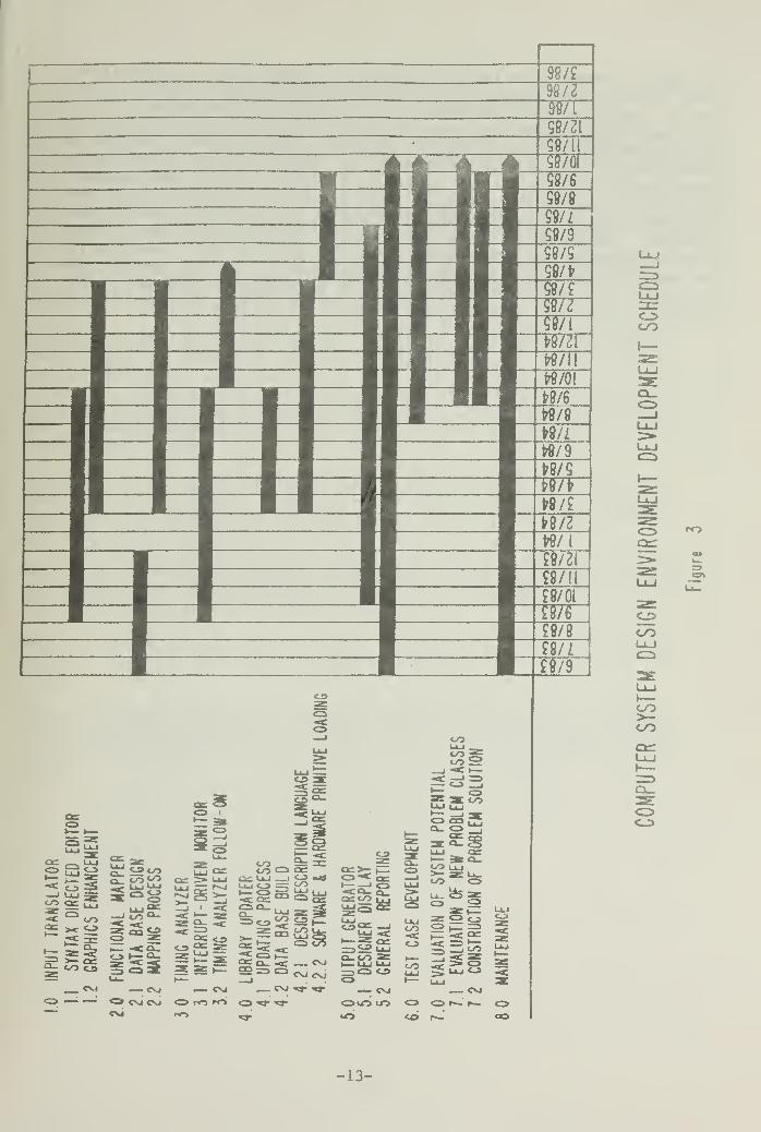
C. Schedule
Figure 3 illustrates the project milestones. Although thisis a working-level document, the milestones have beenplanned only to the subtask level. Since the thesis pro-jects constitute systems development, it is appropriate thatthe thesis student perform the detailed planning andscheduling of the development. This will help him or her tolearn the process and it will allow him or her to considerhis or her level of participation for any quarter.
VII. Summary
The Computer Systems Design Environment Project is an effortto assist the computer systems designer by "talking his
-12-
CO
r«0
co
co
COCO
£Sco
o_ coy? ae
co asU-l ^S u3Q CO
CO Lu>- as u_CO Q
CO ii= 3= _ ^ Q_QC t/jQO: QC^; >_ C3Uj ai U-i __j <-3 «<» C3^ eac —J
if ZffiU «C9- «c >CJ>
~2cCO CD
C\J
CD
<_> i— cu zf; -«c=>^:
1o3 ISP gs= Sczi
>S2-co
C_3 -C => CO
~ c\j — csj — cvj
CSJ CVJ C3 ro "O C3 *»• *»CVJ
— cvj — cvj
OUO in CD O r—' f—' olO co f^- ob
OCO
-13-
language" when interfacing with him, accurately generatingthe system which will satisfy his requirements, and provid-ing a verification mechanism for validating the solution tohis problem. The software for the Computer Systems DesignEnvironment will be developed primarily by thesis studentsusing accepted software engineering techniques with guidancefrom thesis advisors and assistance from staff personnel.The data collected during this project will be stored andaccessed using a commercially available data base managementsystem. The CSDE will be a prototype system which will ini-tially address very specific problem classes and eventuallyas many classes as can be implemented. If the prototypeanswers the questions adequately, a production system willthen be developed patterned from the prototype.
-14-

Bibl iographyComputer System Design Environment
M. N. Matelan, "Automating the Design of Dedicated Real TimeControl Systems," Preprint UCRL-78651 Lawrence LivermoreLaboratory, August 21, 1976.
Alan A. Ross, "Feasibility Demonstration of an AutomatedDesign System," SIGDA Newsletter, Vol 7, No. 1, March 1977.
Alan A. Ross, and Herschel H. Loomis, "Computer Aided Designof Microprocessor-Based Systems," Procreedings of the 15thDesign Automation Conference, June 1978.
Alan A. Ross, "Computer Aided Design of Microprocessor-BasedControllers" PhD. Dissertation, University of California atDavis, 1978.
Hobart S. Cable, II, "Super-Cad: An Integrated Structurefor Design Automation," M.S. Thesis, Air Force Institute ofTechnology, 1982.
Alan A. Ross, Herschel H. Loomis, and George G. Pollock,"Real Time Systems: An Approach to Computer-Aided Design ofHardware and Software," Presented at the 20th Annual Aller-ton Conference, October 7, 1982.
Barbara J. Sherlock, "User-Friendly, Syntax Directed InputTo A Computer Aided Design System," M.S. Thesis, Naval Post-graduate School, June, 1983.
Martin R. Heilstedt, "Automated Design of Microprocessor-Based Digital Filters," Naval Postgraduate School, June,1983.
Alan A. Ross, "Computer Systems Design Environment - ProjectProposal," Presented to Office of Naval Research and DeputyUnder Secretary of Defense for C3I for Evaluation, May,1983.
-15-
APPENDIX AGUIDE TO THE PREPARATION
OF SOFTWARE DEVELOPMENT DOCUMENTATION
A. Guide to the Preparation of Software Development Docu-mentation
The following paragraphs provide a guideline for the writingof each document required during the software developmentprocess. These documents will be written at appropriatetimes during the systems development cycle.
A.l. Requirements Document
The purpose of the Requirements Document is to define "what"the system should be able to do. The process used to obtainthis information was described previously. The documentrequirements will follow that same analysis and designapproach. Figure A-l is an outline of the document contentsand structure.
A. 2. Program Specifications
The purpose of the Program Specification is to describe"HOW" the system requirements will be met. The specifieddata and logic required are described. Figure A-2 is anoutline of the specification content and structure, and Fig-ure A-3 is a sample form for documenting changes to existingprograms.
A. 3. Program Maintenance Manual
The purpose of the Maintenance Manual is to provide guidanceto individuals who, in the future, may attempt to understandand/or modify the program. The amount of additional informa-tion required for this document is somewhat dependent on thelevel of detail of the program specification. The Mainte-nance Manual will be a combination of the Program Specifica-tion (current with the existing program), additionaldetailed logic (if required), test data, test results and a
source listing. The student should place himself or herselfin the position of someone unfamiliar with the program andtry to detail the logic enough to provide a clear under-standing of the program.
Comments should be provided liberally within the programs.They should be highlighted with asterisks (or equivalents)to make them noticeable. If the language has a compiler, a
cross-reference list and object code should be included withthe source. Test data necessary to thoroughly test the
-16-

program should be included along with corresponding testresults.
A. 4. User Documentation
The purpose of the User Documentation is to provide guidancefor the end user of the program/system on its use. "HELP"screens will be used whenever practical so that user docu-mentation can be reviewed online. A printed supplement willbe written to provide guidance in areas where online accessis not practical, e.g., program failures, system failures,logging on and running the program, and how to use help.Figure A-4 describes the contents and structure of the UserDocumentation. Since certain tasks lend themselves more toonline user documentation than others, the split betweenwhat is going to be online and what will be in the supple-mentary document will be made by the thesis student. Thissplit should be described in the "Purpose of the Document"Section of the Users' Manual.
-17-

REQUIREMENTS DOCUMENT OUTLINE
I. Purpose of the Document - This section discusses thesignificance of the Requirements Document in the developmentcycle. In the research environment, this document will bemore technical in nature than the normal data processingdevelopment environment. The key point which must be madein this paragraph is that without a clear definition of"WHAT" the system needs to be able to do, the "WHAT" that isdeveloped will not necessarily be the "WHAT" that isrequired
.
II. Functional Decomposition - This section illustratesthe functional breakdown of the module. Hierarchical blockdiagrams will be used to illustrate this breakdown. Anumbering scheme will be used which relates a higher-levelfunction to its lower-level subfunctions. Remember that afunction at any level is exactly equivalent to the combina-tion of its subfunctions.
III. Function Description - This section contains a oneparagraph description of each function and subfunction. Asthe functions and subfunctions get smaller in scope, thedescriptions will be more detailed.
IV. Description of Data - This section identifies anddefines each category of data required by the module. Allknown data elements are identified for each category. Adata dictionary should be generated containing this informa-tion.
V. Data-to-Function Relationship - This section describesthe flow of data through functions. This illustration canbe accomplished on one chart or a combination of several,one for each major process in the module. A narrative walk-through should accompany the charts.
VI. Transaction Identification - This section illustratesthe transactions required to drive the module. It is recom-mended that proposed screen layouts be included.
VII. Summary - This section, as its name implies, summar-izes the requirements of the system.
FIGURE A-l
-18-
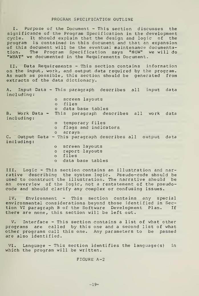
PROGRAM SPECIFICATION OUTLINE
I. Purpose of the Document - This section discusses thesignificance of the Program Specification in the developmentcycle. It should explain that the design and logic of theprogram is contained in this document and that an expansionof this document will be the eventual maintenance documenta-tion. The Program Specification says "HOW" we will doH WHAT M we documented in the Requirements Document.
II. Data Requirements - This section contains informationon the input, work, and output data required by the program.As much as possible, this section should be generated fromextracts of the data dictionary.
A. Input Data - This paragraph describes all input dataincluding
:
o screen layoutso fileso data base tables
B. Work Data - This paragraph describes all work dataincluding
:
o temporary fileso flags and indicatorso arrays
C. Output Data - This paragraph describes all output dataincl uding
:
o screen layoutso report layoutso fileso data base tables
III. Logic - This section contains an illustration and nar-rative describing the system logic. Pseudo-code should beused to construct the illustration. The narrative should bean overview of the logic, not a restatement of the pseudo-code and should clarify any complex or confusing issues.
IV. Environment - This section contains any specialenvironmental considerations beyond those identified in Sec-tion VI paragraph B of the Software Development Plan. Ifthere are none, this section will be left out.
V. Interface - This section contains a list of what otherprograms are called by this one and a second list of whatother programs call this one. Any parameters to be passedare also identified.
VI. Language - This section identifies the language(s) inwhich the program will be written.
FIGURE A-2
-19=

PROGRAM MODIFICATION SPECIFICATION
NAME OF PROGRAM:
DATE:
NAME OF PERSON MAKING CHANGE:
CHANGES TO DATA REQUIREMENTS:
CHANGES TO LOGIC:
CHANGES TO INTERFACE;
MISCELLANEOUS CHANGES:
REQUIRED COMPLETION DATE:
REQUEST DATE:
REQUESTED BY:
FIGURE A-3
-20-
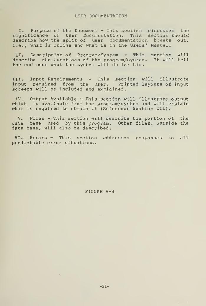
USER DOCUMENTATION
I. Purpose of the Document - This section discusses thesignificance of User Documentation. This section shoulddescribe how the split of user documentation breaks out,i.e., what is online and what is in the Users' Manual.
II. Description of Program/System - This section willdescribe the functions of the program/system. It will tellthe end user what the system will do for him.
III. Input Requirements - This section will illustrateinput required from the user. Printed layouts of inputscreens will be included and explained.
IV. Output Available - This section will illustrate outputwhich is available from the program/system and will explainwhat is required to obtain it (Reference Section III).
V. Files - This section will describe the portion of thedata base used by this program. Other files, outside thedata base, will also be described.
VI. Errors - This section addresses responses to allpredictable error situations.
FIGURE A-4
-21-
INITIAL DISTRIBUTION LIST
Defense Technical Information Center 2
Cameron StationAlexandria, VA 22314
Dudley Knox Library 2
Code 0142Naval Postgraduate SchoolMonterey, CA 93943
Office of Research Administration 1
Code 012ANaval Postgraduate SchoolMonterey, CA 93943
Chairman, Code 52Hq 40Department of Computer ScienceNaval Postgraduate SchoolMonterey, CA 93943
Professor Alan A. Ross, Code 52Rs 15
Department of Computer ScienceNaval Postgraduate SchoolMonterey, CA 93943
-22-


DUDLEY KNOX LIBRARYI "I II 11:1 II
3 2768 00342453 2