Embed Size (px)
Citation preview
Cummins Inc QSM11
Base Engine Data Sheet D353020CX03
Industrial Market
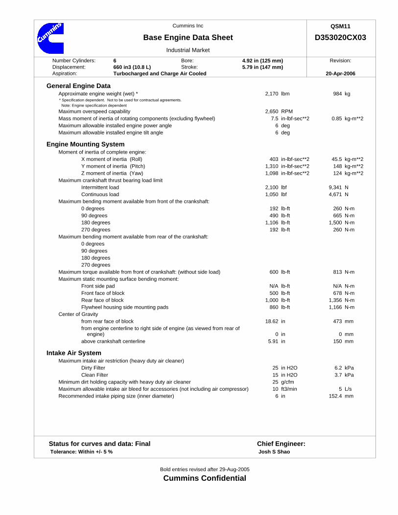
Number Cylinders: 6 Bore: 4.92 in (125 mm) Revision:Displacement: 660 in3 (10.8 L) Stroke: 5.79 in (147 mm)Aspiration: Turbocharged and Charge Air Cooled 20-Apr-2006
General Engine DataApproximate engine weight (wet) * 2,170 984lbm kg
* Specification dependent. Not to be used for contractual agreements. Note: Engine specification dependent
Maximum overspeed capability 2,650 RPMMass moment of inertia of rotating components (excluding flywheel) 7.5 0.85in-lbf-sec**2 kg-m**2Maximum allowable installed engine power angle 6 degMaximum allowable installed engine tilt angle 6 deg
Engine Mounting SystemMoment of inertia of complete engine:
X moment of inertia (Roll) 403 45.5in-lbf-sec**2 kg-m**2Y moment of inertia (Pitch) 1,310 148in-lbf-sec**2 kg-m**2Z moment of inertia (Yaw) 1,098 124in-lbf-sec**2 kg-m**2
Maximum crankshaft thrust bearing load limitIntermittent load 2,100 9,341lbf NContinuous load 1,050 4,671lbf N
Maximum bending moment available from front of the crankshaft:0 degrees 192 260lb-ft N-m90 degrees 490 665lb-ft N-m180 degrees 1,106 1,500lb-ft N-m270 degrees 192 260lb-ft N-m
Maximum bending moment available from rear of the crankshaft:0 degrees90 degrees180 degrees270 degrees
Maximum torque available from front of crankshaft: (without side load) 600 813lb-ft N-mMaximum static mounting surface bending moment:
Front side pad N/A N/Alb-ft N-mFront face of block 500 678lb-ft N-mRear face of block 1,000 1,356lb-ft N-mFlywheel housing side mounting pads 860 1,166lb-ft N-m
Center of Gravityfrom rear face of block 18.62 473in mmfrom engine centerline to right side of engine (as viewed from rear of
engine) 0 0in mmabove crankshaft centerline 5.91 150in mm
Intake Air SystemMaximum intake air restriction (heavy duty air cleaner)
Dirty Filter 25 6.2in H2O kPaClean Filter 15 3.7in H2O kPa
Minimum dirt holding capacity with heavy duty air cleaner 25 g/cfmMaximum allowable intake air bleed for accessories (not including air compressor) 10 5ft3/min L/sRecommended intake piping size (inner diameter) 6 152.4in mm
Status for curves and data: Final Chief Engineer: Tolerance: Within +/- 5 % Josh S Shao
Bold entries revised after 29-Aug-2005
Cummins Confidential

D353020CX03 (Continued) Page: 2
Exhaust SystemMaximum allowable static bending moment @ exhaust outlet flange 20 27lb-ft N-mExhaust manifold/turbocharger blanketing acceptable No
Cooling SystemEngine cooling circuitCoolant system type 1 Pump-1 LoopMinimum operating block coolant temperature 160 71deg F deg CMinimum fill rate 5 19gpm L/minMaximum initial fill time 5 minMinimum water pump inlet pressure with non-deaerating or partially deaerating
cooling system N/A N/Ain-Hg kPaMinimum water pump inlet pressure with fully deaerating cooling system 0 0in-Hg kPaMaximum static head of coolant above crankshaft centerline 46 14ft mMinimum pressure cap rating at sea level 7 48psi kPaMaximum pressure cap rating at sea level 15 103psi kPaMinimum coolant expansion space (% of system capacity) 6 %Maximum deaeration time 25 minAcceptable types of deaeration systems Fully deaeratingMinimum drawdown (% total cooling system capacity) 11 %Full ON Fan engine coolant outlet temperature 203 95deg F deg CIntake manifold air temperature derate/alarm temperature 185 85deg F deg CShutter opening temperature - intake manifold air (CAC) 120 49deg F deg CShutter opening temperature - coolant 185 85deg F deg CMaximum allowable accessory coolant flow 10 38gpm L/minCoolant capacity - engine only 10 9.5quarts LMaximum recommended external coolant flow restriction in engine circuit: 5 34psi kPaEngine coolant circuit thermostat opening temperature: 180 82deg F deg CEngine coolant circuit thermostat fully open temperature 200 93deg F deg C
Thermostat out coolant flow vs. external restriction for engine system (with open thermostat)
System RestrictionEngine 2.5 psi 5 psi 7.5 psi 10 psiSpeed (17 kPa) (34 kPa) (52 kPa) (69 kPa)RPM gpm L/min gpm L/min gpm L/min gpm L/min
1,300 63 238 58 220 47 178 30 1141,500 77 291 70 265 63 238 57 2161,800 91 344 87 329 83 314 78 2952,000 103 390 99 375 95 360 91 3442,200 109 413 108 409 106 401 103 390
Minimum block coolant pressure at speed (open thermostat without radiator cap)RPM psi kPa1,300 7 481,500 12.5 861,800 15.4 1062,000 19.9 1372,200 22.8 157
Lubrication SystemMaximum lube oil flow to all accessories 2 8gpm L/minMaximum oil sump temperature 275 135deg F deg CMaximum oil pressure spike on cold engine 150 1,034psi kPa
Bold entries revised after 29-Aug-2005
Cummins Confidential
D353020CX03 (Continued) Page: 3
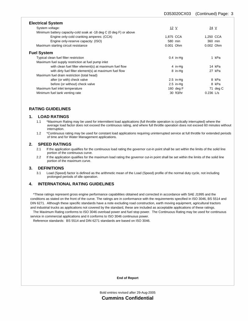
Electrical System12 V 24 VSystem voltage:
Minimum battery capacity-cold soak at -18 deg C (0 deg F) or aboveEngine only-cold cranking amperes: (CCA) 1,875 CCA 1,250 CCAEngine only-reserve capacity: (ISO) 580 min 360 min
Maximum starting circuit resistance 0.001 Ohm 0.002 Ohm
Fuel SystemTypical clean fuel filter restriction 0.4 1in-Hg kPaMaximum fuel supply restriction at fuel pump inlet
with clean fuel filter element(s) at maximum fuel flow 4 14in-Hg kPawith dirty fuel filter element(s) at maximum fuel flow 8 27in-Hg kPa
Maximum fuel drain restriction (total head)after (or with) check valve 2.5 8in-Hg kPabefore (or without) check valve 2.5 8in-Hg kPa
Maximum fuel inlet temperature 160 71deg F deg CMinimum fuel tank venting rate 30 0.236ft3/hr L/s
RATING GUIDELINES
1. LOAD RATINGS 1.1 *Maximum Rating may be used for intermittent load applications (full throttle operation is cyclically interrupted) where the
average load factor does not exceed the continuous rating, and where full throttle operation does not exceed 60 minutes without interruption.
1.2 *Continuous rating may be used for constant load applications requiring uninterrupted service at full throttle for extended periods of time and for Water Management applications.
2. SPEED RATINGS2.1 If the application qualifies for the continuous load rating the governor cut-in point shall be set within the limits of the solid line
portion of the continuous curve. 2.2 If the application qualifies for the maximum load rating the governor cut-in point shall be set within the limits of the solid line
portion of the maximum curve.
3. DEFINITIONS3.1 Load (Speed) factor is defined as the arithmetic mean of the Load (Speed) profile of the normal duty cycle, not including
prolonged periods of idle operation.
4. INTERNATIONAL RATING GUIDELINES
*These ratings represent gross engine performance capabilities obtained and corrected in accordance with SAE J1995 and the conditions as stated on the front of the curve. The ratings are in conformance with the requirements specified in ISO 3046, BS 5514 and DIN 6271. Although these specific standards have a note excluding road construction, earth moving equipment, agricultural tractors and industrial trucks as applications not covered by the standard, these are included as acceptable applications of these ratings. The Maximum Rating conforms to ISO 3046 overload power and fuel stop power. The Continuous Rating may be used for continuous service in commercial applications and it conforms to ISO 3046 continuous power. Reference standards: BS 5514 and DIN 6271 standards are based on ISO 3046.
End of Report
Bold entries revised after 29-Aug-2005
Cummins Confidential


![Acid Base [Search Engine Powerpoint.com]](https://img.pdfslide.us/doc/110x75/577cc9f91a28aba711a51628/acid-base-search-engine-powerpointcom.jpg)