Embed Size (px)
Citation preview

IPPT Reports on Fundamental Te hnologi al Resear h, 47, 4, 43�47, 2013Institute of Fundamental Te hnologi al Resear h, WarszawaPolish A ademy of S ien esPIEZOELECTRIC VALVE FOR CONTROLLED PNEUMATIC SHOCK ABSORBERRafaª WISZOWATY1, Jan BICZYK2
1 Institute of Fundamental Te hnologi al Resear hPolish A ademy of S ien esDepartment of Intelligent Te hnologiesPawi«skiego 5B, 02-106 Warszawa, Polande-mail: rwisz�ippt.pan.pl2 Adaptroni a sp. z o.o.Szpitalna 32, 05-092 �omianki, Polande-mail: jbi zyk�adaptroni a.plRe eived 29 November 2013, published online 2 De ember 2013Abstra t: The work presents the idea of a valve equipped with an ampli�ed piezoele tri a tuator(APAR© � Cedrat Te hnologies), designed for the use in an adaptive pneumati sho k absorber, whi his onsidered as a landing gear of a small air raft or unmanned aerial system. The idea of adaptation toimpa t onditions is based on the ontrolling the �uid �ow between two hambers of the absorber. Inthe onsidered method �ow intensity through the valve determines the absorber rea tion. Utilizationof the piezoele tri a tive element (APA) allows for fast a ting of the system. A prototype of the valveand the absorber were reated. The tests of the mass �ow rate were performed.Key words: valve, piezovalve, a tuation, piezoele tri a tuator, APA, mass �ow rates, landing gear.1. Introdu tionAdaptive landing gear (ALG) is a landing gear system whi h allows to adjust itsdissipative hara teristi s to the speed of des ent during tou hdown. The motivationfor the implementation of ALG system is to a hieve better e� ien y than in the aseof the most ommon gas-oil landing gears whi h have to operate by some range of air- raft masses and des ent rates. In pra ti e, if the absorber is optimized for a ertainnarrow range of onditions, it will not work optimally by wide range of impa t param-eters. The use of adaptive pneumati absorbers gives the possibility of a semi-a tive ontrol, whi h is hara terized by low a tivation energy of the system, and allows fora signi� ant extension of the impa t velo ity and energy range by whi h the absorberoperates optimally. The additional advantage of the pneumati under arriages is alsotheir relatively low weight.

44 Rafaª Wiszowaty, Jan Bi zyk2. Adaptive landing gearThe on ept of adaptive innovative pneumati under arriage is based on the use oftwo- hamber pneumati absorber and a valve that ontrols the �ow of gas between the hambers. The relatively short time of tou hdown is around 100�200 ms. Be ause ofthis fa t the maximum valve response time was limited in advan e to be not greaterthan 2 ms. Su h a performan e is possible to be ondu ted by the utilization of thevalve based on piezoele tri sta k, the so- alled piezo-valve [1℄. The devi e an operatenot only as a sho k absorber dissipating kineti energy of a landing airplane, but alsoas a suspension damper of an air raft, used during ground maneuvers.Adjusting adaptive absorber to the urrent landing onditions is based on the strat-egy that in ludes the following steps:1. Real-time re ognition of impa t energy based on the tou hdown speed.2. Real-time ontrol of the piezoele tri valve opening to maintain a onstant for ea ting on the piston and, thus, to ontrol the energy dissipation pro ess.The former step might be realized by a velo ity identi� ation system, whi h per-forms dete tion of verti al velo ity just before the tou hdown. Alternatively, the landingpro ess parameters might be approximated by measuring the strength of the wheel in-tera tion with the ground.The latter step is performed by measuring the pressures of the working mediumin the hambers of the absorber. This provides an input to the ontrol algorithm im-plemented on the piezo-valve driving ir uit. The obje tive of the ontrol algorithmis to de rease the rea tion for e on the under arriage. The for e should be onstantthroughout the possibly big part of the piston stroke performed inside the ylinder ofthe absorber � to minimize the level of the for e a ting on the air raft stru ture.3. The valve testsMaximum impa t velo ities by whi h the absorber ould operate e� iently dependmainly on the valve �ow apa ity as well as the piston and piston rod diameters. Morespe i� ally, to keep the absorber rea tion on a required level, it is ne essary to ensuresu� ient intensive gas migration between the hambers. Be ause of that, mass �owrates of the gas �owing through the valve are ru ial for the absorber performan e, andwere the subje t of the presented investigation.Piezoele tri pneumati valve was prepared for tests. Its omponents are shown inFig. 1, and the view of the valve installed on the test stand is shown in Fig. 2.Fig. 1. Valve omponents.
Piezoele tri valve for ontrolled pneumati sho k absorber 45
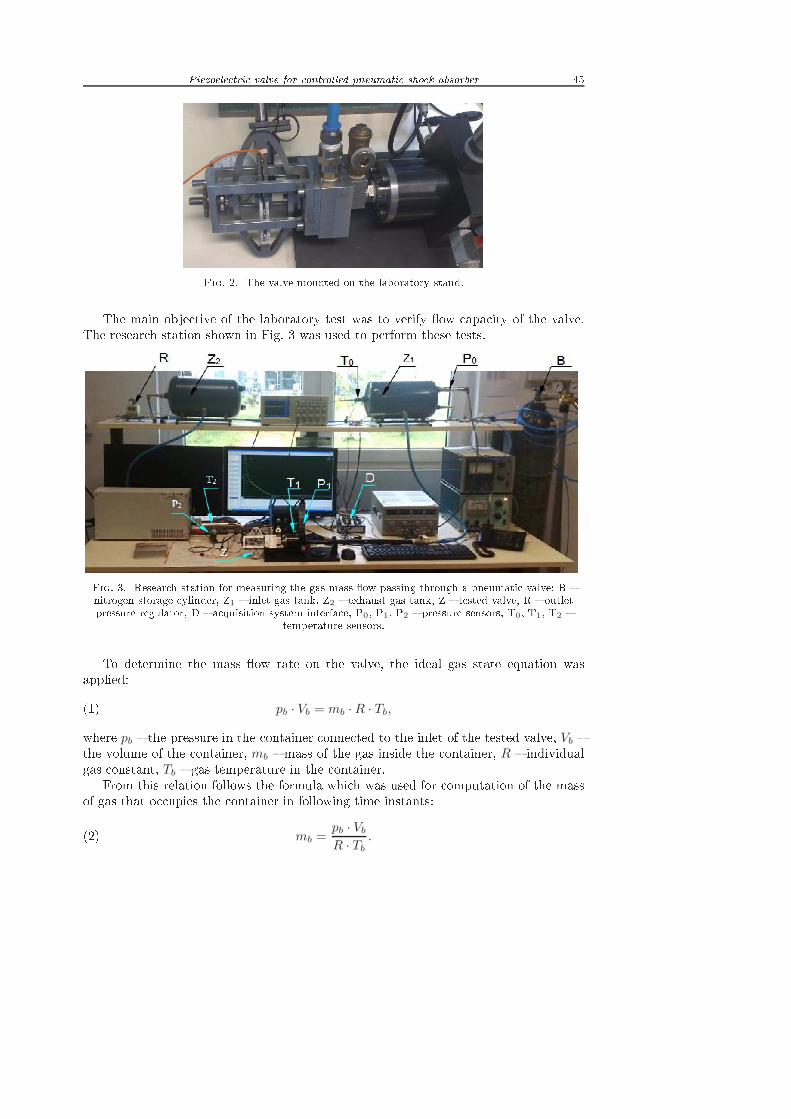
Fig. 2. The valve mounted on the laboratory stand.The main obje tive of the laboratory test was to verify �ow apa ity of the valve.The resear h station shown in Fig. 3 was used to perform these tests.
Fig. 3. Resear h station for measuring the gas mass �ow passing through a pneumati valve: B �nitrogen storage ylinder, Z1 � inlet gas tank, Z2 � exhaust gas tank, Z � tested valve, R � outletpressure regulator, D � a quisition system interfa e, P0, P1, P2 � pressure sensors, T0, T1, T2 �temperature sensors.To determine the mass �ow rate on the valve, the ideal gas state equation wasapplied:(1) pb · Vb = mb ·R · Tb,where pb � the pressure in the ontainer onne ted to the inlet of the tested valve, Vb �the volume of the ontainer, mb � mass of the gas inside the ontainer, R � individualgas onstant, Tb � gas temperature in the ontainer.From this relation follows the formula whi h was used for omputation of the massof gas that o upies the ontainer in following time instants:(2) mb =pb · Vb
R · Tb
.

46 Rafaª Wiszowaty, Jan Bi zykDi�erentiation of this equation was arried out on a basis of the fa t that the volumeof the ontainer is �xed. The mass �ow rate of the gas es aping from this ontainer inarbitrary time instant an be determined from the following relationship:(3) mb = limt2→t1
pb(t2)Vb
R · Tb(t2)−
pb(t1)Vb
R · Tb(t1)
t2 − t1.Full information about the �ow apa ity of the valve is ontained in the hara teristi of the mass �ow rate of the gas as a fun tion of pressure and temperature at the inletand the pressure di�eren e prevailing at the inlet and at the outlet of the valve. In theseries of trials mass �ow rate measurements by various inlet and outlet pressures wereperformed. During ea h trial the value of the gas pressure in the ontainer onne ted tothe valve inlet was de reased while the outlet pressure hanged within some range thatwas restri ted by the pressure regulator R (Fig. 3). Exemplary fun tions of pressure andtemperature of gas, before entering and after leaving the valve, are situated in Figs. 4aand 4b. The results were obtained for the initial inlet pressures 1.3 MPa and initialoutlet pressures set in sequen e 1.1, 1.0, 0.8, 0.6, 0.4, 0.2, 0.1 MPa. The most rapid hanges in pressure and temperature o urred immediately after the valve opening.The upstream and downstream pressures be ome balan ed after 4 s (see Fig. 4a) atthe value of 0.7 MPa. Then, a de rease of both pressures was observed at the rate of15 kPa/s. The temperature of gas entering the valve was dropped by 18 K under theinitial temperature. The temperature of gas leaving the valve was de reased by 4 K.After 5 se onds, this temperature was maintained at a onstant level.a) b)
Fig. 4. a) Exemplary hanges of upstream and downstream gas pressure of the valve, b) exemplary hanges of gas temperature before entering and after leaving the valve.The resear h allowed to determine the hara teristi s of the valve (Fig. 5). Mass �owrate of the valve is strongly dependent on both the di�erential pressure as well as onupstream pressure. The maximum a hieved mass �ow rate was approximately 35 g/sand o urred at the highest di�erential pressure (about 1 MPa). Obtained values aresu� ient to manage with impa ts of obje ts having kineti energy of 50 J and velo ityabove 3 m/s, while the applied absorber has 32 mm diameter, the piston rod diameterequals 12 mm, the maximum piston stroke is 110 mm and the initial pressure is set at0.6 MPa [2℄.

Piezoele tri valve for ontrolled pneumati sho k absorber 47
Fig. 5. Mass �ow rate hara teristi as a fun tion of the pressure di�eren e of gas before entering(PWLOT) and after leaving (PWYLOT) the tested valve.4. Con lusionsThe investigated valve reveals �ow hara teristi that on�rms the appli abilityof this valve in adaptive landing gears designed for small air rafts. A ording to thepresented results and prior estimations there is expe ted the signi� ant de rease ofloads o urring in the air raft stru ture during tou hdown. That for e redu tion ouldprolong the air raft onstru tion lifetime.A knowledgmentsSubstantive and te hni al assistan e and advi e provided by Krzysztof Sekuªa aregratefully a knowledged.This proje t was ondu ted using �nan ial support of Stru tural Funds in the Opera-tional Programme � Innovative E onomy (IE OP) �nan ed from the European RegionalDevelopment Fund, Proje ts �Innowa yjne te hnologie dla poprawy bezpie ze«stwamaªego lotni twa SWING (Safe-Wing)� (POIG.01.04.00-14-100/09, POIG.04.01.00-14-100/09). Referen es1. G. Mikuªowski, R. Wiszowaty, J. Holni ki-Szul , Chara terization of a piezoele tri valve foran adaptive pneumati sho k absorber, SMART MATERIALS & STRUCTURES 22(12), 125011-1-12, 2013.2. R. Wiszowaty, J. Bi zyk, C. Gra zykowski, G. Mikulowski, Method of impa t energy dis-sipation by the use of the pneumati impa t absorber with a piezo-valve, Fifth ECCOMAS The-mati Conferen e on Smart Stru tures and Materials SMART'11, Saarland University, Saarbrü ken,pp. 640�647, CD, 6�8 July 2011.