Embed Size (px)
Citation preview

CT-VC
©Copyright 2014 Dwyer Instruments, Inc. 2/14
Printed in U.S.A.
DWYER INSTRUMENTS, INC.
P.O. Box 373
Michigan City, IN 46360
Return Service Requested
ofcobc_Layout 1 1/29/14 4:21 PM Page 1

Dwyer Instruments, Inc. produces a broad line of competitively priced valves and valve control products under its Proximity
Controls and W. E. Anderson Division. This catalog provides details of W.E. Anderson’s full valve product line, which includes
globe, butterfly, ball, manifold and solenoid valves. Within each valve type W.E. Anderson offers many different options so that
you can select the proper valve to meet your specific application needs. Proximity Controls also offer valve position indicators,
valve positioners and electric and pneumatic actuators to complete your valve automation package.
Dwyer entered into the valve business in 1989 with the acquisition of Proximity Controls. Proximity Controls manufactures a full
line of position indicating products for valves including the magnetic drive featured in the Mark Series. Dwyer then expanded by
purchasing the rugged Hi-FlowTM control valve line from Taylor in 1991. Besides acquisitions Dwyer has continued to expand
the product line to offer our customers a complete source for all of their valve needs.
In addition to making and selling quality valve products, Dwyer is committed to a standard of customer service – including
competitive prices and knowledgeable, courteous technical support – that generates and sustains long-term relationships. Dwyer Instruments, Inc. - standard terms and conditions of sale
1. Prices and specifications are subject to change without notice.
2. shipping dates are approximate. They are dependent upon credit approval and subject to delays beyond our control.
3. terms: Net 30 days to companies with established credit rating. In the event Buyer fails to fulfill previous terms of payment,or in case Seller shall have any doubt at any time as to Buyer’s financial responsibility, Seller may decline to make furtherdeliveries except upon receipt of cash in advance or other special arrangements.
4. liability Point and title: All material is sold EXW Ex Works Dwyer Instruments, Inc. Title to all material sold shall passto buyer upon delivery by Seller to carrier at shipping point.
5. state and local taxes: Any taxes which the Seller may be required to pay or collect upon or with respect to the sale,purchase, delivery, use or consumption of any of the material covered hereby shall be for the account of the Buyer andshall be added to the purchase price.
6. special tooling, dies, silk screens and molds acquired specially to produce goods for Buyer remain the property of DwyerInstruments, Inc., and may not be removed. They will be maintained in good condition for a minimum period of three yearsfrom the date of the original purchase order.
7. export orders: Terms, discounts and conditions of sale for purchase orders originating or for shipment to final destinationsoutside the U.S.A. will be furnished upon request.
8. limited warranty: The Seller warrants all Dwyer instruments and equipment to be free from defects in workmanship ormaterial under normal use and service for a period of one year from date of shipment. Liability under this warranty is limitedto repair or replacement EXW Ex Works Dwyer Instruments, Inc of any parts which prove to be defective within that time orrepayment of the purchase price at the Seller’s option provided the instruments have been returned, transportation prepaid,within one year from date of purchase. All technical advice, recommendations and services are based on technical dataand information which the Seller believes to be reliable and are intended for use by persons having skill and knowledge ofthe business, at their own discretion. In no case is Seller liable beyond replacement of equipment EXW Ex Works DwyerInstruments, Inc or the full purchase price. This warranty does not apply if the maximum ratings label is removed or if theinstrument or equipment is abused, altered, used at ratings above the maximum specified, or otherwise misused in anyway.
THIS EXPRESS LIMITED WARRANTY IS IN LIEU OF AND EXCLUDES ALL OTHER REPRESENTATIONS MADE BYADVERTISEMENTS OR BY AGENTS AND ALL OTHER WARRANTIES, BOTH EXPRESS AND IMPLIED. THERE ARENO IMPLIED WARRANTIES OF MERCHANTABILITY OR OF FITNESS FOR A PARTICULAR PURPOSE FOR GOODSCOVERED HEREUNDER.
9. Buyer’s remedies: THE BUYER’S EXCLUSIVE AND SOLE REMEDY ON ACCOUNT OF OR IN RESPECT TO THEFURNISHING OF NON-CONFORMING OR DEFECTIVE MATERIAL SHALL BE TO SECURE REPLACEMENT THEREOFAS AFORESAID. THE SELLER SHALL NOT IN ANY EVENT BE LIABLE FOR THE COST OF ANY LABOR EXPENDEDON ANY SUCH MATERIAL OR FOR ANY SPECIAL, DIRECT, INDIRECT, CONSEQUENTIAL OR INCIDENTAL DAMAGESTO ANYONE BY REASON OF THE FACT THAT IT SHALL HAVE BEEN NON-CONFORMING OR DEFECTIVE.
10. Acceptance: All orders shall be subject to the terms and conditions contained or referred to in the Seller’s quotation,acknowledgment, and to those listed here and to no others whatsoever. No waiver, alteration or modification of these termsand conditions shall be binding unless in writing and signed by an executive officer of the Seller. All orders are subject towritten acceptance by Dwyer Instruments, Inc., Michigan City, Indiana, U.S.A.
note:
Each item (model, range, part number, etc.) is discountedindependently. In an order for more than one item, differentitems cannot be combined to earn a greater discount.
Most items are subject to STANDARD schedule at right.
Prices followed by the symbol b are subject to discountsper schedule B.
Certain items such as repairs, repair parts, EXPL and WP
housings, prices followed by the symbol n, special scaleand tag charges are priced at net and earn no discount.
InDustrIAl DIscount scheDule*
QuAntItyoF eAch
Item
1-24
25-99
100-249
250-499
500-Up
Net
5%
10%
15%
20%
Net
Net
5%
10%
15%
DIscounts
stAnDArD scheDule B
*Please contact us for discount schedules for other account types.
Dwyer Instruments, Inc. - DIscount scheDule
RIGHT CHOICE. RIGHT PRICE. RIGHT NOW. STANDARD TERMS & CONDITIONS OF SALE
ifcibc_Layout 1 2/3/14 9:56 AM Page 1

ORDERING IS EASY FROM DWYER
PHONEIn the U.S. call toll free:
800/872-9141
Outside the U.S. call:
219/879-8000
FAX219/872-9057
WEBSITESwww.weavalves.comwww.dwyer-inst.comwww.proximitycontrols.com
LOCAL SUPPORT GLOBALLY
INTERNATIONAL CUSTOMERS
Dwyer has local distributors in over 50 countries. Contact the office of your country or contact the corporate headquarters to find
your local distributor. You can also go to our website at the following address to be contacted by your local distributor:
http://www.dwyer-inst.com/Distributors/DistContactInfo.cfm.
Corporate Headquarters
DWYER INSTRUMENTS, INC.
102 Indiana Highway 212,
P.O. Box 373
Michigan City, IN 46360, U.S.A.
PHONE FAX
219/879-8000 219/872-9057
United Kingdom
DWYER INSTRUMENTS LTD
Unit 16, The Wye Estate, London Road
High Wycombe, Bucks HP11 1LH-U.K.
PHONE FAX
(+44) (0) 1494 461707 (+44) (0) 1494 465102
Australia
DWYER INSTRUMENTS, PTY. LTD.
Unit 1, 11 Waverley Drive
Unanderra, NSW 2526 Australia
PHONE FAX
(+61) (0) 2 4272 2055 (+61) (0) 2 4272 4055
Hong Kong
DWYER INSTRUMENTS HK, LTD.
Unit 605A, 6/F, Shui Hing Centre
13 Sheung Yuet Road, Kowloon Bay, Hong Kong
PHONE FAX
+852-23181007 +852-27561565
OTHER CONTACTS
TECHNICAL
SUPPORT
LITERATURE
REQUESTS
QUOTATION/
BID REQUESTS
GENERAL
INFORMATION
1CONTACT US | U.S. 219/879-8000 | U.K. (+44) (0)1494-461707 | A.U. (+61) (0) 2 4272 2055 | China +852-23181007
001_Layout 2 1/29/14 3:05 PM Page 1

CUSTOMER SERVICE
PRODUCT DELIVERY
TECHNICAL SUPPORT
All of our technical sales staff are degreed engineers trained to be product and
industry experts. We listen to your needs and get you the answers you want
quickly.
WE HELP YOU FIND A SOLUTION
TO CONTACT A TECHNICAL SUPPORT ENGINEER
PHONE
219/879-8000
FAX
219/872-9057
REAL PEOPLE
Courteous and professional customer service representatives are available via
phone and email to process and provide assistance with your order. Dwyer
provides industry leading response time to answer your call quickly without
making you wait.
PRICING
Contact us for formal quotes, Dwyer offers bids and project quotes. Discounts
are available for particular customer types based on quantities purchased.
LARGE INVENTORY LOCATED CENTRALLY IN THE U.S.
Dwyer is committed to get you your order quickly with more than 5,000 line
items in stock in our Michigan City, Indiana headquarters and in most cases
lead times less than two weeks for non-stock products.
FAST PROCESSING AND PACKING
Our dedicated shipping staff packs and ships your order the same day on stock
items ordered before 2:00 PM U.S. Central Time.
FLEXIBLE SHIPPING
Dwyer offers blanket orders for OEM’s to schedule out your product shipments
to be when you need them. Contact us for details.
• Product Selection
• Application Assistance
• Regulatory and Agency Approval
Compliance
• Installation Guidance
• Maintenance and Repair
• Product Customization for OEM’s
FRIENDLY & FAST
PROMPT & ACCURATE
KNOWLEDGEABLE & HELPFUL
W.E. ANDERSON | www.weavalves.com2
002_Layout 2 1/29/14 3:08 PM Page 1

TABLE OF CONTENTS
Application Drawings . . . . . . . . . . . . . . . . . . . . . . . . . . . . . . . . . . . . . . . . . . . . . . . . . . . . . . . . . . . . . . . . . . . . . . . . . . . . . . .4-5
BALL
Series WE01, 2-Piece NPT Stainless Steel Ball Valve . . . . . . . . . . . . . . . . . . . . . . . . . . . . . . . . . . . . . . . . . . . . . . . . . . . . . .6-7
Series WE02, 3-Piece NPT Stainless Steel Ball Valve . . . . . . . . . . . . . . . . . . . . . . . . . . . . . . . . . . . . . . . . . . . . . . . . . . . . . .8-9
Series WE03, 3-Piece Tri-Clamp Stainless Steel Ball Valve . . . . . . . . . . . . . . . . . . . . . . . . . . . . . . . . . . . . . . . . . . . . . . . .10-11
Series WE04, 2-Piece Flanged Stainless Steel Ball Valve . . . . . . . . . . . . . . . . . . . . . . . . . . . . . . . . . . . . . . . . . . . . . . . . .12-13
Series WE31, 3-Way NPT Stainless Steel Ball Valve . . . . . . . . . . . . . . . . . . . . . . . . . . . . . . . . . . . . . . . . . . . . . . . . . . . . .14-15
Series WE33, 3-Way Tri-Clamp Stainless Steel Ball Valve . . . . . . . . . . . . . . . . . . . . . . . . . . . . . . . . . . . . . . . . . . . . . . . . .16-17
Series WE34, 3-Way Flanged Stainless Steel Ball Valve . . . . . . . . . . . . . . . . . . . . . . . . . . . . . . . . . . . . . . . . . . . . . . . . . .18-19
Series MV, Mini Brass Ball Valve . . . . . . . . . . . . . . . . . . . . . . . . . . . . . . . . . . . . . . . . . . . . . . . . . . . . . . . . . . . . . . . . . . . . . . .20
Series SMV, Mini Stainless Steel Ball Valve . . . . . . . . . . . . . . . . . . . . . . . . . . . . . . . . . . . . . . . . . . . . . . . . . . . . . . . . . . . . . . .21
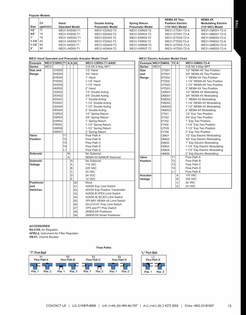
Series DBV, Brass Ball Valve . . . . . . . . . . . . . . . . . . . . . . . . . . . . . . . . . . . . . . . . . . . . . . . . . . . . . . . . . . . . . . . . . . . . . . . . . .22
GLOBE
Introduction to the Hi-Flow™ Valve . . . . . . . . . . . . . . . . . . . . . . . . . . . . . . . . . . . . . . . . . . . . . . . . . . . . . . . . . . . . . . . . . . . .23
Selecting the Proper Valve . . . . . . . . . . . . . . . . . . . . . . . . . . . . . . . . . . . . . . . . . . . . . . . . . . . . . . . . . . . . . . . . . . . . . . . . . . .24
Actuators . . . . . . . . . . . . . . . . . . . . . . . . . . . . . . . . . . . . . . . . . . . . . . . . . . . . . . . . . . . . . . . . . . . . . . . . . . . . . . . . . . . . . . . . .25
Valve Operation . . . . . . . . . . . . . . . . . . . . . . . . . . . . . . . . . . . . . . . . . . . . . . . . . . . . . . . . . . . . . . . . . . . . . . . . . . . . . . . . . . . .26
Trim Styles . . . . . . . . . . . . . . . . . . . . . . . . . . . . . . . . . . . . . . . . . . . . . . . . . . . . . . . . . . . . . . . . . . . . . . . . . . . . . . . . . . . . . . . .27
Valve Sizing . . . . . . . . . . . . . . . . . . . . . . . . . . . . . . . . . . . . . . . . . . . . . . . . . . . . . . . . . . . . . . . . . . . . . . . . . . . . . . . . . . . . .28-29
Flow Capacity, Cv - Linear Characteristic . . . . . . . . . . . . . . . . . . . . . . . . . . . . . . . . . . . . . . . . . . . . . . . . . . . . . . . . . . . . . . . .30
Flow Capacity, Cv - Equal Percentage Characteristic . . . . . . . . . . . . . . . . . . . . . . . . . . . . . . . . . . . . . . . . . . . . . . . . . . . . . . .31
Hi-Flow™ Control Valves . . . . . . . . . . . . . . . . . . . . . . . . . . . . . . . . . . . . . . . . . . . . . . . . . . . . . . . . . . . . . . . . . . . . . . . . . .32-36
LIN-E-AIRE® Pneumatic Valve Actuator . . . . . . . . . . . . . . . . . . . . . . . . . . . . . . . . . . . . . . . . . . . . . . . . . . . . . . . . . . . . . . . . .37
Series 2000VA, Hi-Flow™ Control Valves Body Only . . . . . . . . . . . . . . . . . . . . . . . . . . . . . . . . . . . . . . . . . . . . . . . . . . . . . . .38
Series 2000VA, Flanged Hi-Flow™ Control Valves Body Only . . . . . . . . . . . . . . . . . . . . . . . . . . . . . . . . . . . . . . . . . . . . . . . .39
Series 38R, Self-Acting Temperature Control Valve . . . . . . . . . . . . . . . . . . . . . . . . . . . . . . . . . . . . . . . . . . . . . . . . . . . . . .40-49
BUTTERFLY
Series SAE, Butterfly Valve . . . . . . . . . . . . . . . . . . . . . . . . . . . . . . . . . . . . . . . . . . . . . . . . . . . . . . . . . . . . . . . . . . . . . . . . . . .50
Series BFV, Butterfly Valve . . . . . . . . . . . . . . . . . . . . . . . . . . . . . . . . . . . . . . . . . . . . . . . . . . . . . . . . . . . . . . . . . . . . . . . . . . . .51
ACTUATORS
Series ACT, Pneumatic and Electric Actuators . . . . . . . . . . . . . . . . . . . . . . . . . . . . . . . . . . . . . . . . . . . . . . . . . . . . . . . . . .52-53
SOLENOID
Series SN, NAMUR Mount Solenoid Valve . . . . . . . . . . . . . . . . . . . . . . . . . . . . . . . . . . . . . . . . . . . . . . . . . . . . . . . . . . . . . . . .54
Reference Tables . . . . . . . . . . . . . . . . . . . . . . . . . . . . . . . . . . . . . . . . . . . . . . . . . . . . . . . . . . . . . . . . . . . . . . . . . . . . . . . .55-56
3CONTACT US | U.S. 219/879-8000 | U.K. (+44) (0)1494-461707 | A.U. (+61) (0) 2 4272 2055 | China +852-23181007
003_Layout 2 1/29/14 3:09 PM Page 1

APPLICATION DRAWINGS
Regulating pH for food and dairy applications using
linear or rotary pneumatic control valves.
Hi-Flow™ pneumatic control valve, available with bronze or 316 stainless steel
body and 316 stainless steel trim, provides superior corrosion resistance and
durability. The Hi-Flow™ valves yield superb flow characteristics and enhanced
shut-off capabilities ensuring years of trouble-free, reliable operation. In the
application shown, throttle action of the High-Flow™ linear globe valve is used
to regulate the flow of acid solution into a food/dairy process to accurately
control the pH of the system.
W.E. ANDERSON | www.weavalves.com4
W.E. Anderson® Series Hi-Flow™ valves are used for flow
control of water into industrial boilers.
Maintaining the proper water level in a boiler is critical to its proper operation.
Too much water and water can get into the steam lines, while too little water
and the boiler can over heat. Both conditions can lead to damage of the boiler
or heating system. Feedwater going into the boiler needs to be controlled to
maintain the proper boiler water level. The W. E. Anderson® Hi-Flow™ globe
valve is used to control the flow of the feedwater to maintain that proper water
level. The control valve is used with a proportioning electric actuator that is
directly controlled by a level transmitter in the boiler. As the water level drops
in the boiler the valve lets in more water and as water level increases the valve
lets in less water. Thus proper water levels are always maintained keeping the
boiler operating properly and efficiently.
Proximity™ Mark Series valve position indicator is perfect
for valve position indication on offshore oil rigs.
Proximity™ Mark Series position indicator is utilized in valve automation
packages in harsh environments. The Mark Series mounts onto the top of
rotary valve actuators and connects to the actuator shaft or attaches to the
shaft of a linear valve for indicating valve position. Standard with the Mark
Series is visual position indication with “OPEN”, “CLOSED”, and degree
position status. The Mark Series is available with continuous position
retransmission with a 4 to 20 mA output and up to six adjustable position
indication switches for remote indication of valve status. Remote status
transmitter is used for indication of exact valve position and switches provide
discrete indication of valve open and closed status in the control room. The
Mark Series is perfect for this application because of the 316 SS enclosure
that withstands the sea spray environment, and the magnetic drive mechanism
that completely seals the switch cavity from the environment.
Quick response Hi-Flow™ valves control water flow in
cooling process.
Dependable W.E. Anderson® Hi-Flow™ control valves with Lin-E-Aire® air-to-
raise actuators combine to provide unsurpassed water flow management. This
retort system employs the Hi-Flow™ valve because of its excellent control
capabilities, which are necessary for this application. After the cooking process,
the valve is opened slowly. Once the desired temperature has been reached,
the supply is shut off and any additional cooling is done by use of the hand
valve.
004_Layout 2 1/31/14 11:22 AM Page 1

APPLICATION DRAWINGS
Visual valve position indication with Proximity®
explosion-proof position indicators provides
convenience and enhanced safety in valve monitoring.
For the convenience of the control valve user, a compact, adjustable stainless
steel visual indicator is provided on all direct-drive Proximity® position indicating
switches and transmitters. These industrial switches are commonly mounted on
quarter-turn pneumatic actuators and valves. A magnetic design provides
maximum safety by allowing complete sealing of the switch cavity. Over 2000
specific applications are covered with an extensive line of mounting kits built for
individual valve and actuator brands and model numbers. As the valve and
actuator is cycled, the input shaft of the position indicator rotates, causing a
stainless steel cylinder to rotate inside a second stainless steel cylinder with
windows. When the valve is open the word “OPEN” appears in the two
windows located 180° apart. The compact and durable visual indicator displays
discrete endpoints (OPEN or CLOSED) as well as scaled degrees (0-90). LED
and flow path outputs are available options. Up to 3 conduit entrances allow
utilization of this flexible indicator as a junction box for additional convenience
as well as material and labor cost reduction to the user.
5
Process temperature control using pneumatic Hi-Flow™
control valves.
Pneumatic Hi-Flow™ control valves provide excellent control with high flow,
wide rangeability and tight shutoff capabilities. The dispensing application
shown uses a Lin-E-Aire® pneumatic actuator, operating off standard 3-15 psi
control air signals, and a Hi-Flow™ linear control valve that apportions steam
or water to a user process. The valve regulates cooling water or steam flow
depending on the process requirement resident in the temperature controller
program. This package can be provided with a Precisor® positioner and
Proximity™ position transmitter which provides an excellent process control
application problem solution.
Regulating process temperature using W.E. Anderson®
self-acting temperature control valve.
The self-acting temperature control valve features a self-contained valve,
controller, and sealed thermal system in one compact package providing
installation economy and long-term reliability. This package eliminates the
temperature controller required with standard control valves. The dispensing
application shown includes a 38R valve that opens when the temperature in the
hot water tank decreases allowing the steam to heat the water and bring the
temperature up to a required set point, at which point the valve will close. A
valve that closes on temperature rise (direct acting) would be required for this
application. The W.E. Anderson® Hi-Flow™ quick-opening, double seated valve
enables fast response for improved process control in this application. If your
application requires valve to open on temperature rise, then a reverse acting
38R is also offered.
W.E. Anderson® Series SAE Butterfly Valves are utilized
on hydraulic reservoirs on injection molding machines.
The SAE valve is used as a shut off valve on the hydraulic system on injection
molding machines. Normally the valve is in the open position during operation.
When the hydraulic pump needs servicing the valve is closed to isolate the
hydraulic reservoir to prevent loss of hydraulic fluid. The SAE valve has
connections conforming to SAE J518, which is a four screw split flange port. An
o-ring seal is utilized in the connection design that reduces leaks associated
with tapered thread and gasket type seals. The connection allows for the
reduction of unneeded adapters and has a low profile reducing space
requirements.
CONTACT US | U.S. 219/879-8000 | U.K. (+44) (0)1494-461707 | A.U. (+61) (0) 2 4272 2055 | China +852-23181007
005_Layout 2 1/31/14 11:28 AM Page 1

BA
LL
6 W.E. ANDERSON | www.weavalves.com
The Series WE01 incorporates a fullport 2-piece SS ball valve for great flowrates with minimal pressure drop. Thevalve features a blowout proof stem foradded safety, reinforced PTFE seats andseals for longer life, and a 316 SS (ASTMCF8M) ball for better performance.Actuators are direct mounted creating acompact assembly for tight spaces. Limitswitches are able to be mounted directlyto the valves allowing for remote positionindication. The Series WE01 can be configuredwith either an electric or pneumaticactuator. Electric actuators are availablein weatherproof or explosion-proof, avariety of supply voltages and two-position or modulating control. Two-position actuators use the supply voltageto drive the valve open or closed, whilethe modulating actuator accepts a 4 to20 mA input for valve positioning.Actuators feature thermal overloadprotection and permanently lubricatedgear train.
The pneumatic double acting actuatoruses an air supply to drive the valveopen and closed. The actuator has twosupply ports, with one driving the valveopen and the other driving the valveclosed. Spring return pneumaticactuators use the air supply to open thevalve and internally loaded springsreturn the valve to the closed position.Also available is the SN solenoid valve toelectrically switch the air supplypressure between the air supply portsfor opening and closing the valve.Actuators are constructed of anodizedand epoxy coated aluminum for years ofcorrosion free service.
FEATURES
• Capable of being configured to fit
any application
• Limit switches can be mounted to
manual valves for remote
monitoring
SPECIFICATIONS
VALVE
Service: Compatible liquids and
gases.
Body: 2-piece.
Line Sizes: 1/2 to 3˝.
End Connections: Female NPT.
Pressure Limits: 20˝ Hg to 1000
psi (-0.7 to 69 bar).
Wetted Materials:
Body and Ball: 316 SS (CF8M);
Stem: 316SS;
Seat: RTFE/PTFE;
Seal, Washer and Packing: PTFE.
Temperature Limits: -20 to 392°F
(-29 to 200°C).
Other Materials:
O-ring: Fluoroelastomer;
Handle: 304 SS;
Washer: 301 SS;
Stem Nut, Locking Device,
Gland Ring: 304SS;
Handle Sleeve: PVC.
ACTUATORS
Pneumatic “DA” and “SR” Series
Type: DA series is double acting
and SR series is spring return (rack
and pinion).
Normal Supply Pressure:
DA: 40 to 115 psi (2.7 to 7.9 bar);
SR: 80 psi (5.5 bar).
Maximum Supply Pressure: 120
psi (8.6 bar).
Air Connections:
DA01: 1/8˝ female NPT;
DA02 to DA05: 1/4˝ female NPT;
SR02 to SR07: 1/4˝ female NPT.
Housing Material: Anodized
aluminum body and epoxy coated
aluminum end caps.
Temperature Limits: -40 to 176°F
(-40 to 80°C).
Accessory Mounting: NAMUR
standard.
Electric “TD” and “MD” Series
Power Requirements: 110 VAC,
220 VAC, 24 VAC or 24 VDC (MD
models not available in 24 VDC).
Power Consumption: See manual.
Cycle Time (per 90°):
TD01 4 s;
MD01: 10 s;
TD02 and MD02: 20 s;
TD03 and MD03: 30 s.
Duty Rating: 85%.
Enclosure Rating: NEMA 4X
(IP67).
Housing Material: Powder coated
aluminum.
Temperature Limits: -22 to 140°F
(-30 to 60°C).
Electrical Connection: 1/2˝ female
NPT.
Modulating Input: 4 to 20 mA.
Standard Features: Manual
override, position indicator, and TD
models come with two limit
switches.
Electric “TI” and “MI” Series
Power Requirements: 110 VAC,
220 VAC, 24 VAC or 24 VDC.
Power Consumption: See manual.
Cycle Time (per 90°):
TI01 and MI01: 2.5 s;
TI02 and MI02: 5 s;
TI03 and MI03: 5 s;
TI04 and MI04: 10 s;
TI05 and MI06: 15 s.
Duty Rating:
Two-Position: TI01-TI06: 25%;
Modulating: MI01-MI06: 75%.
Enclosure Rating: NEMA 7.
Housing Material: Powder coated
aluminum.
Temperature Limits: -40 to 140°F
(-40 to 60°C).
Electrical Connection: 1/2˝ female
NPT.
Modulating Input: 4 to 20 mA.
Standard Features: Position
indicator and two limit switches.
2-Piece NPT Stainless Steel Ball ValveFull Port, Vented Ball, Electric or Pneumatic Actuators
Series
WE01
WE01-EDA02
WE01-EDA02-AA05
WE01-EHD00
WE01-ETD01-A
WE01-ETI02-A
W
006_Layout 1 1/29/14 3:46 PM Page 1

BA
LL
7
Size
1/2˝
3/4˝
1˝
1-1/4˝
1-1/2˝
2˝
2-1/2˝
3˝
Cv
(gal/min)
36.64
67.69
110.27
184.73
266.62
485.3
791.57
1151.95
Example
Series
Size and
Actuator
Solenoid
Solenoid
Voltage
Positioner
and
Switches
Options
WE01
WE01
EDA02
CHD00
DHD00
EHD00
FHD00
GHD00
HHD00
IHD00
JHD00
CDA01
DDA01
EDA02
FDA02
GDA03
HDA03
IDA04
JDA05
CSR02
DSR02
ESR03
FSR03
GSR04
HSR05
ISR07
JSR07
A
N
A
A
N
A
B
C
D
E
01
00
01
02
03
04
05
06
07
08
09
NO
Example
Series
Size and
Actuator
Actuator
Voltage
WE01
WE01
GMD02
CTD01
DTD01
ETD01
FTD01
GTD02
HTD02
ITD03
JTD03
CMD01
DMD01
EMD01
FMD01
GMD02
HMD02
IMD03
JMD03
CTI01
DTI01
ETI02
FTI02
GTI02
HTI04
ITI05
JTI06
CMI01
DMI01
EMI02
FMI02
GMI02
HMI04
IMI05
JMI06
A
A
B
C
D
WE01 Electric Actuator Model ChartWE01 Hand Operated and Pneumatic Actuator Model Chart
Popular Models
CONTACT US | U.S. 219/879-8000 | U.K. (+44) (0)1494-461707 | A.U. (+61) (0) 2 4272 2055 | China +852-23181007
WE01-EDA02-AA01
316 SS 2-Piece
1/2˝ Hand Operated
3/4˝ Hand Operated
1˝ Hand Operated
1-1/4˝ Hand Operated
1-1/2˝ Hand Operated
2˝ Hand Operated
2-1/2˝ Hand Operated
3˝ Hand Operated
1/2˝ Double Acting
3/4˝ Double Acting
1˝ Double Acting
1-1/4˝ Double Acting
1-1/2˝ Double Acting
2˝ Double Acting
2-1/2˝ Double Acting
3˝ Double Acting
1/2˝ Spring Return
3/4˝ Spring Return
1˝ Spring Return
1-1/4˝ Spring Return
1-1/2˝ Spring Return
2˝ Spring Return
2-1/2˝ Spring Return
3˝ Spring Return
No Solenoid
NEMA 4X NAMUR Solenoid
No Solenoid
110 VAC
220 VAC
24 VAC
24 VDC
12 VDC
None
42AD0 Exp Limit Switch
45VD0 Exp Position Transmitter
42AD0-B ATEX Limit Switch
42AD0-IE IECEX Limit Switch
VPI-M01 NEMA 4X Limit Switch
QV-210101 Poly Limit Switch
VPS and P1 Prox Switch
265ER-D5 Positioner
285ER-D5 Smart Positioner
Fail Open Spring Return Actuator
WE01-GMD02-A
316 SS 2-Piece
1/2˝ NEMA 4X Two-Position
3/4˝ NEMA 4X Two-Position
1˝ NEMA 4X Two-Position
1-1/4˝ NEMA 4X Two-Position
1-1/2˝ NEMA 4X Two-Position
2˝ NEMA 4X Two-Position
2-1/2˝ NEMA 4X Two-Position
3˝ NEMA 4X Two-Position
1/2˝ NEMA 4X Modulating
3/4˝ NEMA 4X Modulating
1˝ NEMA 4X Modulating
1-1/4˝ NEMA 4X Modulating
1-1/2˝ NEMA 4X Modulating
2˝ NEMA 4X Modulating
2-1/2˝ NEMA 4X Modulating
3˝ NEMA 4X Modulating
1/2˝ Exp Two-Position
3/4˝ Exp Two-Position
1˝ Exp Two-Position
1-1/4˝ Exp Two-Position
1-1/2˝ Exp Two-Position
2˝ Exp Two-Position
2-1/2˝ Exp Two-Position
3˝ Exp Two-Position
1/2˝ Exp Electric Modulating
3/4˝ Exp Electric Modulating
1˝ Exp Electric Modulating
1-1/4˝ Exp Electric Modulating
1-1/2˝ Exp Electric Modulating
2˝ Exp Electric Modulating
2-1/2˝ Exp Electric Modulating
3˝ Exp Electric Modulating
110 VAC
220 VAC
24 VAC
24 VDC
ACCESSORIES
R2-2120, Air Regulator
AFR2-2, Instrument Air Filter Regulator
VB-01, Volume Booster
Hand
Operated
Model
WE01-CHD00
WE01-DHD00
WE01-EHD00
WE01-FHD00
WE01-GHD00
WE01-HHD00
WE01-IHD00
WE01-JHD00
Double Acting
Pneumatic
Model
WE01-CDA01
WE01-DDA01
WE01-EDA02
WE01-FDA02
WE01-GDA03
WE01-HDA03
WE01-IDA04
WE01-JDA05
Spring Return
Pneumatic
Model
WE01-CSR02
WE01-DSR02
WE01-ESR03
WE01-FSR03
WE01-GSR04
WE01-HSR05
WE01-ISR07
WE01-JSR07
NEMA 4X Two-
Position Electric
(110 VAC) Model
WE01-CTD01-A
WE01-DTD01-A
WE01-ETD01-A
WE01-FTD01-A
WE01-GTD02-A
WE01-HTD02-A
WE01-ITD03-A
WE01-JTD03-A
NEMA 4X
Modulating Electric
(110 VAC) Model
WE01-CMD01-A
WE01-DMD01-A
WE01-EMD01-A
WE01-FMD01-A
WE01-GMD02-A
WE01-HMD02-A
WE01-IMD03-A
WE01-JMD03-A
007_Layout 1 1/29/14 3:47 PM Page 1

BA
LL
8 W.E. ANDERSON | www.weavalves.com
The Series WE02 incorporates a fullport 3-piece SS ball valve for great flowrates with minimal pressure drop. Thevalve features a blowout proof stem foradded safety, reinforced PTFE seats andseals for longer life, and a 316 SS (ASTMCF8M) ball for better performance.Actuators are direct mounted creating acompact assembly for tight spaces. Limitswitches are able to be mounted directlyto the valves allowing for remote positionindication. The Series WE02 can be configuredwith either an electric or pneumaticactuator. Electric actuators are availablein weatherproof or explosion-proof, avariety of supply voltages and two-position or modulating control. Two-position actuators use the supply voltageto drive the valve open or closed, whilethe modulating actuator accepts a 4 to20 mA input for valve positioning.Actuators feature thermal overloadprotection and permanently lubricatedgear train.
The pneumatic double acting actuatoruses an air supply to drive the valveopen and closed. The actuator has twosupply ports, with one driving the valveopen and the other driving the valveclosed. Spring return pneumaticactuators use the air supply to open thevalve, and internally loaded springsreturn the valve to the closed position.Also available is the SN solenoid valve toelectrically switch the air supplypressure between the air supply portsfor opening and closing the valve.Actuators are constructed of anodizedand epoxy coated aluminum for years ofcorrosion free service.
FEATURES
• Capable of being configured to fit
any application
• Limit switches can be mounted to
manual valves for remote
monitoring
SPECIFICATIONS
VALVE
Service: Compatible liquids and
gases.
Body: 3-piece.
Line Sizes: 1/2 to 3˝ .
End Connections: Female NPT.
Pressure Limits: 20˝ Hg to 1000
psi (-0.7 to 69 bar).
Wetted Materials:
Body and ball: 316 SS (CF8M);
Stem: 316 SS;
Seat: RTFE/PTFE;
Seal, Washer, and Packing: PTFE.
Temperature Limits: -20 to 392°F
(-29 to 200°C).
Other Materials:
O-ring: Fluoroelastomer;
Handle: 304 SS;
Washer: 301 SS;
Stem Nut, Locking Device,
Gland Ring: 304 SS;
Handle Sleeve: PVC.
ACTUATORS
Pneumatic “DA” and “SR” Series
Type: DA series is double acting
and SR series is spring return (rack
and pinion).
Normal Supply Pressure:
DA: 40 to 115 psi (2.7 to 7.9 bar);
SR: 80 psi (5.5 bar).
Maximum Supply Pressure: 120
psi (8.6 bar).
Air Connections:
DA01: 1/8˝ female NPT;
DA02 to DA05: 1/4˝ female NPT;
SR02 to SR07: 1/4˝ female NPT.
Housing Material: Anodized
aluminum body and epoxy coated
aluminum end caps.
Temperature Limits: -40 to 176°F
(-40 to 80°C).
Accessory Mounting: NAMUR
standard.
Electric “TD” and “MD” Series
Power Requirements: 110 VAC,
220 VAC, 24 VAC or 24 VDC (MD
models not available in 24 VDC).
Power Consumption: See manual.
Cycle Time (per 90°):
TD01: 4 s;
MD01: 10 s;
TD02 and MD02: 20 s;
TD03 and MD03: 30 s.
Duty Rating: 85%.
Enclosure Rating: NEMA 4X
(IP67).
Housing Material: Powder coated
aluminum.
Temperature Limits: -22 to 140°F
(-30 to 60°C).
Electrical Connection: 1/2˝ female
NPT.
Modulating Input: 4 to 20 mA.
Standard Features: Manual
override, position indicator, and TD
models come with two limit
switches.
Electric “TI” and “MI” Series
Power Requirements: 110 VAC,
220 VAC, 24 VAC or 24 VDC.
Power Consumption: See manual.
Cycle Time (per 90°):
TI01 and MI01: 2.5 s;
TI02 and MI02: 5 s;
TI03 and MI03: 5 s;
TI04 and MI04: 10 s;
TI05 and MI05: 15 s.
Duty Rating:
Two-Position: TI01-TI05: 25%;
Modulating: MI01-MI05: 75%.
Enclosure Rating: NEMA 7.
Housing Material: Powder coated
aluminum.
Temperature Limits: -40 to 140°F
(-40 to 60°C).
Electrical Connection: 1/2˝ female
NPT.
Modulating Input: 4 to 20 mA.
Standard Features: Position
indicator and two limit switches.
3-Piece NPT Stainless Steel Ball ValveFull Port, Vented Ball, Electric or Pneumatic Actuators
Series
WE02
WE02-DDA01
WE02-DDA01-AA01
WE02-DHD00
WE02-DTD01-A
WE02-CTI01-A
W
008_Layout 1 1/29/14 3:47 PM Page 1

BA
LL
9
Size
1/2˝
3/4˝
1˝
1-1/4˝
1-1/2˝
2˝
2-1/2˝
3˝
Cv
(gal/min)
36.64
67.69
110.27
184.73
266.62
485.3
791.57
1151.95
Example
Series
Size and
Actuators
Solenoid
Solenoid
Voltage
Positioner
and
Switches
Options
WE02
WE02
CSR02
CHD00
DHD00
EHD00
FHD00
GHD00
HHD00
IHD00
JHD00
CDA01
DDA01
EDA02
FDA02
GDA03
HDA03
IDA04
JDA05
CSR02
DSR02
ESR03
FSR03
GSR04
HSR05
ISR07
JSR07
N
N
A
N
N
A
B
C
D
E
09
00
01
02
03
04
05
06
07
08
09
NO
Example
Series
Size and
Actuators
Actuator
Voltage
WE02
WE02
EDT01
CTD01
DTD01
ETD01
FTD01
GTD02
HTD02
ITD03
JTD03
CMD01
DMD01
EMD01
FMD01
GMD02
HMD02
IMD03
JMD03
CTI01
DTI01
ETI02
FTI02
GTI03
HTI04
ITI05
JTI05
CMI01
DMI01
EMI02
FMI02
GMI03
HMI04
IMI05
JMI05
B
A
B
C
D
WE02 Electric Actuator Model ChartWE02 Hand Operated and Pneumatic Actuator Model Chart
Popular Models
CONTACT US | U.S. 219/879-8000 | U.K. (+44) (0)1494-461707 | A.U. (+61) (0) 2 4272 2055 | China +852-23181007
WE02-CSR02-NN09
316SS 3-Piece NPT
1/2˝ Hand Operated
3/4˝ Hand Operated
1˝ Hand Operated
1-1/4˝ Hand Operated
1-1/2˝ Hand Operated
2˝ Hand Operated
2-1/2˝ Hand Operated
3˝ Hand Operated
1/2˝ Double Acting
3/4˝ Double Acting
1˝ Double Acting
1-1/4˝ Double Acting
1-1/2˝ Double Acting
2˝ Double Acting
2-1/2˝ Double Acting
3˝ Double Acting
1/2˝ Spring Return
3/4˝ Spring Return
1˝ Spring Return
1-1/4˝ Spring Return
1-1/2˝ Spring Return
2˝ Spring Return
2-1/2˝ Spring Return
3˝ Spring Return
No Solenoid
NEMA 4X NAMUR Solenoid
No Solenoid
110 VAC
220 VAC
24 VAC
24 VDC
12 VDC
None
42AD0 Exp Limit Switch
45VD0 Exp Position Transmitter
42AD0-B ATEX Limit Switch
42AD0-IE IECEX Limit Switch
VPI-M01 NEMA 4X Limit Switch
QV-210101 Poly Limit Switch
VPS and P1 Prox Switch
265ER-D5 Positioner
285ER-D5 Smart Positioner
Fail Open Spring Return Actuator
WE02-ETD01-B
316SS 3-Piece NPT
1/2˝ NEMA 4X Two-Position
3/4˝ NEMA 4X Two-Position
1˝ NEMA 4X Two-Position
1-1/4˝ NEMA 4X Two-Position
1-1/2˝ NEMA 4X Two-Position
2˝ NEMA 4X Two-Position
2-1/2˝ NEMA 4X Two-Position
3˝ NEMA 4X Two-Position
1/2˝ NEMA 4X Modulating
3/4˝ NEMA 4X Modulating
1˝ NEMA 4X Modulating
1-1/4˝ NEMA 4X Modulating
1-1/2˝ NEMA 4X Modulating
2˝ NEMA 4X Modulating
2-1/2˝ NEMA 4X Modulating
3˝ NEMA 4X Modulating
1/2˝ Exp Two-Position
3/4˝ Exp Two-Position
1˝ Exp Two-Position
1-1/4˝ Exp Two-Position
1-1/2˝ Exp Two-Position
2˝ Exp Two-Position
2-1/2˝ Exp Two-Position
3˝ Exp Two-Position
1/2˝ Exp Electric Modulating
3/4˝ Exp Electric Modulating
1˝ Exp Electric Modulating
1-1/4˝ Exp Electric Modulating
1-1/2˝ Exp Electric Modulating
2˝ Exp Electric Modulating
2-1/2˝ Exp Electric Modulating
3˝ Exp Electric Modulating
110 VAC
220 VAC
24 VAC
24 VDC
ACCESSORIES
R2-2120, Air Regulator
AFR2-2, Instrument Air Filter Regulator
VB-01, Volume Booster
Hand
Operated
Model
WE02-CHD00
WE02-DHD00
WE02-EHD00
WE02-FHD00
WE02-GHD00
WE02-HHD00
WE02-IHD00
WE02-JHD00
Double Acting
Pneumatic
Model
WE02-CDA01
WE02-DDA01
WE02-EDA02
WE02-FDA02
WE02-GDA03
WE02-HDA03
WE02-IDA04
WE02-JDA05
Spring Return
Pneumatic
Model
WE02-CSR02
WE02-DSR02
WE02-ESR03
WE02-FSR03
WE02-GSR04
WE02-HSR05
WE02-ISR07
WE02-JSR07
NEMA 4X Two-
Position Electric
(110 VAC) Model
WE02-CTD01-A
WE02-DTD01-A
WE02-ETD01-A
WE02-FTD01-A
WE02-GTD02-A
WE02-HTD02-A
WE02-ITD03-A
WE02-JTD03-A
NEMA 4X
ModulatingElectric
(110 VAC) Model
WE02-CMD01-A
WE02-DMD01-A
WE02-EMD01-A
WE02-FMD01-A
WE02-GMD02-A
WE02-HMD02-A
WE02-IMD03-A
WE02-JMD03-A
009_Layout 1 1/29/14 3:48 PM Page 1

BA
LL
10 W.E. ANDERSON | www.weavalves.com
The Series WE03 incorporates a fullport 3-piece tri-clamp SS ball valve forgreat flow rates with minimal pressuredrop. The valve features a blowout proofstem for added safety, reinforced PTFEseats and seals for longer life, and a 316SS (ASTM CF8M) ball for betterperformance. Actuators are directmounted creating a compact assemblyfor tight spaces. Limit switches are ableto be mounted directly to the valvesallowing for remote position indication. The Series WE03 can be configuredwith either an electric or pneumaticactuator. Electric actuators are availablein weatherproof or explosion-proof, avariety of supply voltages and two-position or modulating control. Two-position actuators use the supply voltageto drive the valve open or closed, whilethe modulating actuator accepts a 4 to20 mA input for valve positioning.Actuators feature thermal overloadprotection and permanently lubricatedgear train.
The pneumatic double acting actuatoruses an air supply to drive the valveopen and closed. The actuator has twosupply ports with one driving the valveopen and the other driving the valveclosed. Spring return pneumaticactuators use the air supply to open thevalve and internally loaded springsreturn the valve to the closed position.Also available is the SN solenoid valve toelectrically switch the air supplypressure between the air supply portsfor opening and closing the valve.Actuators are constructed of anodizedand epoxy coated aluminum for years ofcorrosion free service.
FEATURES
• Capable of being configured to fit
any application
• Limit switches can be mounted to
manual valves for remote
monitoring
• Cavity filled valve for sanitary
applications
SPECIFICATIONS
VALVE
Service: Compatible liquids and
gases.
Body: 3-piece.
Line Sizes: 1/2 to 2˝ .
End Connections: Tri-clamp ends.
Pressure Limits: 20˝ Hg to 1000
psi (-0.7 to 69 bar).
Wetted Materials:
Body and ball: 316 SS (CF8M);
Stem: 316 SS;
Seat: RTFE/PTFE;
Seal, Washer, and Packing: PTFE.
Temperature Limits: -20 to 392°F
(-29 to 200°C).
Other Materials:
O-ring: Fluoroelastomer;
Handle: 304 SS;
Washer: 301 SS;
Stem Nut, Locking Device,
Gland Ring: 304 SS;
Handle Sleeve: PVC.
ACTUATORS
Pneumatic “DA” and “SR” Series
Type: DA series is double acting
and SR series is spring return (rack
and pinion).
Normal Supply Pressure:
DA: 40 to 115 psi (2.7 to 7.9 bar);
SR: 80 psi (5.5 bar).
Maximum Supply Pressure: 120
psi (8.6 bar).
Air Connections:
DA01: 1/8˝ female NPT;
DA02: 1/4˝ female NPT;
SR02 to SR04: 1/4˝ female NPT.
Housing Material: Anodized
aluminum body and epoxy coated
aluminum end caps.
Temperature Limits: -40 to 176°F
(-40 to 80°C).
Accessory Mounting: NAMUR
standard.
Electric “TD” and “MD” Series
Power Requirements: 110 VAC,
220 VAC, 24 VAC or 24 VDC (MD
models not available in 24 VDC).
Power Consumption: See manual.
Cycle Time (per 90°):
TD01: 4 s;
MD01: 10 s;
TD02 and MD02: 20 s.
Duty Rating: 85%.
Enclosure Rating: NEMA 4X
(IP67).
Housing Material: Powder coated
aluminum.
Temperature Limits: -22 to 140°F
(-30 to 60°C).
Electrical Connection: 1/2˝ female
NPT.
Modulating Input: 4 to 20 mA.
Standard Features: Manual
override, position indicator, and TD
models come with two limit
switches.
Electric “TI” and “MI” Series
Power Requirements: 110 VAC,
220 VAC, 24 VAC or 24 VDC.
Power Consumption: See manual.
Cycle Time (per 90°):
TI01 and MI01: 2.5 s;
TI02 and MI02: 5 s.
Duty Rating:
Two-Position: TI01-TI02: 25%;
Modulating: MI01-MI02: 75%.
Enclosure Rating: NEMA 7.
Housing Material: Powder coated
aluminum.
Temperature Limits: -40 to 140°F
(-40 to 60°C).
Electrical Connection: 1/2˝ female
NPT.
Modulating Input: 4 to 20 mA.
Standard Features: Position
indicator and two limit switches.
3-Piece Tri-Clamp Stainless SteelBall ValveCavity Filled, Full Port, Electric or Pneumatic Actuators
Series
WE03
WE03-DDA01
WE03-DDA01-AA07
WE03-DHD00
WE03-DTD01-A
WE03-DDA01-AA06
W
010_Layout 1 1/29/14 3:48 PM Page 1

BA
LL
11
Size
1/2˝
3/4˝
1˝
1-1/2˝
2˝
Cv
(gal/min)
14.39
42.25
86.17
223.61
437.98
Example
Series
Size and
Actuator
Solenoid
Solenoid
Voltage
Positioner
and
Switches
Options
WE03
WE03
EDA02
CHD00
DHD00
EHD00
GHD00
HHD00
CDA01
DDA01
EDA02
GDA02
HDA02
CSR02
DSR02
ESR03
GSR04
HSR04
A
N
A
A
N
A
B
C
D
E
06
00
01
02
03
04
05
06
07
08
09
NO
Example
Series
Size and
Actuator
Actuator
Voltage
WE03
WE03
CMD01
CTD01
DTD01
ETD01
GTD01
HTD02
CMD01
DMD01
EMD01
GMD01
HMD02
CTI01
DTI01
ETI02
GTI02
HTI02
CMI01
DMI01
EMI02
GMI02
HMI02
A
A
B
C
D
WE03 Electric Actuator Model ChartWE03 Hand Operated and Pneumatic Actuator Model Chart
Popular Models
CONTACT US | U.S. 219/879-8000 | U.K. (+44) (0)1494-461707 | A.U. (+61) (0) 2 4272 2055 | China +852-23181007
WE02-EDA02-AA06
316 SS 3-Piece Tri-Clamp
1/2˝ Hand Operated
3/4˝ Hand Operated
1˝ Hand Operated
1-1/2˝ Hand Operated
2˝ Hand Operated
1/2˝ Double Acting
3/4˝ Double Acting
1˝ Double Acting
1-1/2˝ Double Acting
2˝ Double Acting
1/2˝ Spring Return
3/4˝ Spring Return
1˝ Spring Return
1-1/2˝ Spring Return
2˝ Spring Return
No Solenoid
NEMA 4X NAMUR Solenoid
No Solenoid
110 VAC
220 VAC
24 VAC
24 VDC
12 VDC
None
42AD0 Exp Limit Switch
45VD0 Exp Position Transmitter
42AD0-B ATEX Limit Switch
42AD0-IE IECEX Limit Switch
VPI-M01 NEMA 4X Limit Switch
QV-210101 Poly Limit Switch
VPS and P1 Prox Switch
265ER-D5 Positioner
285ER-D5 Smart Positioner
Fail Open Spring Return Actuator
WE03-CMD01-A
316 SS 3-Piece Tri-Clamp
1/2˝ NEMA 4X Two-Position
3/4˝ NEMA 4X Two-Position
1˝ NEMA 4X Two-Position
1-1/2˝ NEMA 4X Two-Position
2˝ NEMA 4X Two-Position
1/2˝ NEMA 4X Modulating
3/4˝ NEMA 4X Modulating
1˝ NEMA 4X Modulating
1-1/2˝ NEMA 4X Modulating
2˝ NEMA 4X Modulating
1/2˝ Exp Two-Position
3/4˝ Exp Two-Position
1˝ Exp Two-Position
1-1/2˝ Exp Two-Position
2˝ Exp Two-Position
1/2˝ Exp Electric Modulating
3/4˝ Exp Electric Modulating
1˝ Exp Electric Modulating
1-1/2˝ Exp Electric Modulating
2˝ Exp Electric Modulating
110 VAC
220 VAC
24 VAC
24 VDC
ACCESSORIES
R2-2120, Air Regulator
AFR2-2, Instrument Air Filter Regulator
VB-01, Volume Booster
Hand
Operated
Model
WE03-CHD00
WE03-DHD00
WE03-EHD00
WE03-GHD00
WE03-HHD00
Double Acting
Pneumatic
Model
WE03-CDA01
WE03-DDA01
WE03-EDA02
WE03-GDA02
WE03-HDA02
Spring Return
Pneumatic
Model
WE03-CSR02
WE03-DSR02
WE03-ESR03
WE03-GSR04
WE03-HSR04
NEMA 4X Two-
Position Electric
(110 VAC) Model
WE03-CTD01-A
WE03-DTD01-A
WE03-ETD01-A
WE03-GTD01-A
WE03-HTD02-A
NEMA 4X
Modulating Electric
(110 VAC) Model
WE03-CMD01-A
WE03-DMD01-A
WE03-EMD01-A
WE03-GMD01-A
WE03-HMD02-A
011_Layout 1 1/29/14 3:56 PM Page 1

BA
LL
12 W.E. ANDERSON | www.weavalves.com
The Series WE04 incorporates a fullport 2-piece flanged SS ball valve forgreat flow rates with minimal pressuredrop. The valve features a blowout proofstem for added safety, reinforced PTFEseats and seals for longer life, and a 316SS (ASTM CF8M) ball for betterperformance. Actuators are directmounted creating a compact assemblyfor tight spaces. Limit switches are ableto be mounted directly to the valvesallowing for remote position indication. The Series WE04 can be configuredwith either a pneumatic or electricactuator. Electric actuators are availablein weatherproof or explosion-proof, avariety of supply voltages, and two-position or modulating control. Two-position actuators use the supply voltageto drive the valve open or closed, whilethe modulating actuator accepts a 4 to20 mA input for valve positioning.Actuators feature thermal overloadprotection and permanently lubricatedgear train.
The pneumatic double acting actuatoruses an air supply to drive the valveopen and closed. The actuator has twosupply ports, with one driving the valveopen, and the other driving the valveclosed. Spring return pneumaticactuators use the air supply to open thevalve, and internally loaded springsreturn the valve to the closed position.Also available is the SN solenoid valve toelectrically switch the air supplypressure between the air supply portsfor opening and closing the valve.Actuators are constructed of anodizedand epoxy coated aluminum for years ofcorrosion free service.
FEATURES
• Capable of being configured to fit
any application
• Limit switches can be mounted to
manual valves for remote
monitoring
SPECIFICATIONS
VALVE
Service: Compatible liquids and
gases.
Body: 2-piece.
Line Sizes: 1/2 to 3˝ .
End Connections: 150# ANSI
flange.
Pressure Limits: 20˝ Hg to 275 psi
(-0.7 to 19 bar).
Wetted Materials:
Body and ball: 316 SS (CF8M);
Stem: 316 SS;
Seat: RTFE/PTFE;
Seal, Washer, and Packing: PTFE.
Temperature Limits: -20 to 392°F
(-29 to 200°C).
Other Materials:
O-ring: Fluoroelastomer;
Handle: 304 SS;
Washer: 301 SS;
Stem Nut, Locking Device,
Gland Ring: 304 SS;
Handle Sleeve: PVC.
ACTUATORS
Pneumatic “DA” and “SR” Series
Type: DA series is double acting
and SR series is spring return (rack
and pinion).
Normal Supply Pressure:
DA: 40 to 115 psi (2.7 to 7.9 bar);
SR: 80 psi (5.5 bar).
Maximum Supply Pressure: 120
psi (8.6 bar).
Air Connections:
DA01: 1/8˝ female NPT;
DA02 to DA04: 1/4˝ female NPT
SR02 to SR06: 1/4˝ female NPT.
Housing Material: Anodized
aluminum body and epoxy coated
aluminum end caps.
Temperature Limits: -40 to 176°F
(-40 to 80°C).
Accessory Mounting: NAMUR
standard.
Electric “TD” and “MD” Series
Power Requirements: 110 VAC,
220 VAC, 24 VAC OR 240 VDC (MD
models not available in 24 VDC) .
Power Consumption: See manual.
Cycle Time (per 90°):
TD01: 4 s;
MD01: 10 s;
TD02 and MD02: 20 s;
TD03 and MD03: 30 s.
Duty Rating: 85%.
Enclosure Rating: NEMA 4X
(IP67).
Housing Material: Powder coated
aluminum.
Temperature Limits: -22 to 140°F
(-30 to 60°C).
Electrical Connection: 1/2˝ female
NPT.
Modulating Input: 4 to 20 mA.
Standard Features: Manual
override, position indicator, and TD
models come with two limit
switches.
Electric “TI” and “MI” Series
Power Requirements: 110 VAC,
220 VAC, 24 VAC or 24 VAC.
Power Consumption: See manual.
Cycle Time (per 90°):
TI01 and MI01: 2.5 s;
TI02 and MI02: 5 s;
TI03 and MI03: 5 s;
TI04 and MI04: 10 s;
TI05 and MI05: 15 s.
Duty Rating:
Two-Position: TI01-TI05: 25%;
Modulating: MI01-MI05: 75%.
Enclosure Rating: NEMA 7.
Housing Material: Powder coated
aluminum.
Temperature Limits: -40 to 140°F
(-40 to 60°C).
Electrical Connection: 1/2˝ NPT
female.
Modulating Input: 4 to 20 mA.
Standard Features: Position
indicator and two limit switches.
2-Piece Flanged Stainless Steel Ball Valve150# ANSI Flange, Vented Ball, Electric or Pneumatic Actuators
Series
WE04
WE04-DTD01-A
WE04-DHD00
WE04-DDA02-AA03
WE04-DDA02-NN09
WE04-CTI01-A
W
012_Layout 1 1/29/14 3:56 PM Page 1

BA
LL
13
Size
1/2˝
3/4˝
1˝
1-1/2˝
2˝
2-1/2˝
3˝
Cv
(gal/min)
36.64
67.69
101.63
266.62
485.3
816.9
1121.84
Popular Models
Example
Series
Size and
Actuator
Solenoid
Solenoid
Voltage
Positioner
and
Switches
Options
WE04
WE04
GDA03
CHD00
DHD00
EHD00
GHD00
HHD00
IHD00
JHD00
CDA01
DDA01
EDA02
GDA03
HDA03
IDA04
JDA04
CSR02
DSR02
ESR03
GSR04
HSR05
ISR06
JSR06
A
N
A
B
N
A
B
C
D
E
05
00
01
02
03
04
05
06
07
08
09
NO
WE04 Hand Operated and Pneumatic Actuator Model Chart
Example
Series
Size and
Actuator
Actuator
Voltage
WE04
WE04
ITD02
CTD01
DTD01
ETD01
GTD02
HTD02
ITD03
JTD03
CMD01
DMD01
EMD01
GMD02
HMD02
IMD03
JMD03
CTI01
DTI01
ETI02
GTI03
HTI04
ITI05
JTI05
CMI01
DMI01
EMI02
GMI03
HMI04
IMI04
JMI05
B
A
B
C
D
WE04 Electric Actuator Model Chart
CONTACT US | U.S. 219/879-8000 | U.K. (+44) (0)1494-461707 | A.U. (+61) (0) 2 4272 2055 | China +852-23181007
WE04-GDA03-AB05
316 SS 2-Piece Flanged
1/2˝ Hand Operated
3/4˝ Hand Operated
1˝ Hand Operated
1-1/2˝ Hand Operated
2˝ Hand Operated
2-1/2˝ Hand Operated
3˝ Hand Operated
1/2˝ Double Acting
3/4˝ Double Acting
1˝ Double Acting
1-1/2˝ Double Acting
2˝ Double Acting
2-1/2˝ Double Acting
3˝ Double Acting
1/2˝ Spring Return
3/4˝ Spring Return
1˝ Spring Return
1-1/2˝ Spring Return
2˝ Spring Return
2-1/2˝ Spring Return
3˝ Spring Return
No Solenoid
NEMA 4X NAMUR Solenoid
No Solenoid
110 VAC
220 VAC
24 VAC
24 VDC
12 VDC
None
42AD0 Exp Limit Switch
45VD0 Exp Position Transmitter
42AD0-B ATEX Limit Switch
42AD0-IE IECEX Limit Switch
VPI-M01 NEMA 4X Limit Switch
QV-210101 Poly Limit Switch
VPS and P1 Prox Switch
265ER-D5 Positioner
285ER-D5 Smart Positioner
Fail Open Spring Return Actuator
WE04-ITD02-B
316 SS 2-Piece Flanged
1/2˝ NEMA 4X Two-Position
3/4˝ NEMA 4X Two-Position
1˝ NEMA 4X Two-Position
1-1/2˝ NEMA 4X Two-Position
2˝ NEMA 4X Two-Position
2-1/2˝ NEMA 4X Two-Position
3˝ NEMA 4X Two-Position
1/2˝ NEMA 4X Modulating
3/4˝ NEMA 4X Modulating
1˝ NEMA 4X Modulating
1-1/2˝ NEMA 4X Modulating
2˝ NEMA 4X Modulating
2-1/2˝ NEMA 4X Modulating
3˝ NEMA 4X Modulating
1/2˝ Exp Two-Position
3/4˝ Exp Two-Position
1˝ Exp Two-Position
1-1/2˝ Exp Two-Position
2˝ Exp Two-Position
2-1/2˝ Exp Two-Position
3˝ Exp Two-Position
1/2˝ Exp Electric Modulating
3/4˝ Exp Electric Modulating
1˝ Exp Electric Modulating
1-1/2˝ Exp Electric Modulating
2˝ Exp Electric Modulating
2-1/2˝ Exp Electric Modulating
3˝ Exp Electric Modulating
110 VAC
220 VAC
24 VAC
24 VDC
ACCESSORIES
R2-2120, Air Regulator
AFR2-2, Instrument Air Filter Regulator
VB-01, Volume Booster
Hand
Operated
Model
WE04-CHD00
WE04-DHD00
WE04-EHD00
WE04-GHD00
WE04-HHD00
WE04-IHD00
WE04-JHD00
Double Acting
Pneumatic
Model
WE04-CDA01
WE04-DDA01
WE04-EDA02
WE04-GDA03
WE04-HDA03
WE04-IDA04
WE04-JDA04
Spring Return
Pneumatic
Model
WE04-CSR02
WE04-DSR02
WE04-ESR03
WE04-GSR04
WE04-HSR05
WE04-ISR06
WE04-JSR06
NEMA 4X Two-
Position Electric
(110 VAC) Model
WE04-CTD01-A
WE04-DTD01-A
WE04-ETD01-A
WE04-GTD02-A
WE04-HTD02-A
WE04-ITD03-A
WE04-JTD03-A
NEMA 4X
Modulating Electric
(110 VAC) Model
WE04-CMD01-A
WE04-DMD01-A
WE04-EMD01-A
WE04-GMD02-A
WE04-HMD02-A
WE04-IMD03-A
WE04-JMD03-A
013_Layout 1 1/29/14 3:57 PM Page 1

BA
LL
14 W.E. ANDERSON | www.weavalves.com
The Series WE31 incorporates a fullport 3-way SS ball valve for great flowrates with minimal pressure drop. Thevalve features a blowout-proof stem foradded safety, reinforced PTFE seats andseals for longer life, and a 316 SS (ASTMCF8M) ball for better performance.Actuators are direct mounted creating acompact assembly for tight spaces. Limitswitches are able to be mounted directlyto the valves allowing for remote positionindication. The Series WE31 can be configuredwith either an electric or pneumaticactuator. Electric actuators are availablein weatherproof or explosion-proof, avariety of supply voltages and two-position or modulating control. Two-position actuators use the supply voltageto drive the valve open or closed, whilethe modulating actuator accepts a 4 to20 mA input for valve positioning.Actuators feature thermal overloadprotection and permanently lubricatedgear train.
The pneumatic double acting actuatoruses an air supply to drive the valveopen and closed. The actuator has twosupply ports, with one driving the valveopen and the other driving the valveclosed. Spring return pneumaticactuators use the air supply to open thevalve, and internally loaded springsreturn the valve to the closed position.Also available is the SN solenoid valve toelectrically switch the air supplypressure between the air supply portsfor opening and closing the valve.Actuators are constructed of anodizedand epoxy coated aluminum for years ofcorrosion free service.
FEATURES
• Capable of being configured to fit
any application
• Limit switches can be mounted to
manual valves for remote
monitoring
SPECIFICATIONS
VALVE
Service: Compatible liquids and
gases.
Body: 3-way.
Line Sizes: 1/4 to 2˝.
End Connections: Female NPT.
Pressure Limits: 20˝ Hg to 1000
psi (-0.7 to 69 bar).
Wetted Materials:
Body and ball: 316 SS (CF8M);
Stem: 316 SS;
Seat: RTFE/PTFE;
Seal, Washer, and Packing: PTFE.
Temperature Limits: -20 to 392°F
(-29 to 200°C).
Other Materials:
O-ring: Fluoroelastomer;
Handle: 304 SS;
Washer: 301 SS;
Stem Nut, Locking Device,
Gland Ring: 304 SS;
Handle Sleeve: PVC.
ACTUATORS
Pneumatic “DA” and “SR” Series
Type: DA series is double acting
and SR series is spring return (rack
and pinion).
Normal Supply Pressure:
DA: 40 to 115 psi (2.7 to 7.9 bar);
SR: 80 psi (5.5 bar).
Maximum Supply Pressure: 120
psi (8.6 bar).
Air Connections:
DA01: 1/8˝ female NPT;
DA02 to DA04: 1/4˝ female NPT;
SR03 to SR07: 1/4˝ female NPT.
Housing Material: Anodized
aluminum body and epoxy coated
aluminum end caps.
Temperature Limits: -40 to 176°F
(-40 to 80°C).
Accessory Mounting: NAMUR
standard.
Electric “TD” and “MD” Series
Power Requirements: 110 VAC,
220 VAC, 24 VAC or 24 VDC (MD
models not available in 24 VDC).
Power Consumption: See manual.
Cycle Time (per 90°):
TD01: 4 s;
MD01: 10 s;
TD02 and MD02: 20 s;
TD03 and MD03: 30 s.
Duty Rating: 85%.
Enclosure Rating: NEMA 4X
(IP67).
Housing Material: Powder coated
aluminum.
Temperature Limits: -22 to 140°F
(-30 to 60°C).
Electrical Connection: 1/2˝ female
NPT.
Modulating Input: 4 to 20 mA.
Standard Features: Manual
override, position indicator, and TD
models come with two limit
switches.
Electric “TI” and “MI” Series
Power Requirements: 110 VAC,
220 VAC, 24 VAC or 24 VDC.
Power Consumption: See manual.
Cycle Time (per 90°):
TI01 and MI01: 2.5 s;
TI02 and MI02: 5 s;
TI03 and MI03: 5 s;
TI04 and MI04: 10 s;
TI05 and MI06: 15 s.
Duty Rating:
Two-Position: TI01-TI06: 25%;
Modulating: MI01-MI06: 75%.
Enclosure Rating: NEMA 7.
Housing Material: Powder coated
aluminum.
Temperature Limits: -40 to 140°F
(-40 to 60°C).
Electrical Connection: 1/2˝ female
NPT.
Modulating Input: 4 to 20 mA.
Standard Features: Position
indicator and two limit switches.
3-Way NPT Stainless Steel Ball ValveFull Port, Vented Ball, Electric or Pneumatic Actuators
Series
WE31
WE31-DDA02-L1
WE31-DTD01-T3-A
WE31-DHD00-T1
WE31-DDA02-T1-AA01
WE31-DDA02-T3-NN05
W
014_Layout 1 1/29/14 3:57 PM Page 1
BA
LL
15
Flow Paths
Example
Series
Size and
Range
Valve
Position
Solenoid
Solenoid
Voltage
Positioner
and
Switches
WE31
WE31
CSR03
CHD00
DHD00
EHD00
FHD00
GHD00
HHD00
CDA02
DDA02
EDA03
FDA03
GDA04
HDA04
CSR03
DSR03
ESR04
FSR05
GSR06
HSR07
T1
T1
T2
T3
T4
L1
A
N
A
B
C
D
E
00
00
01
02
03
04
05
06
07
08
09
Example
Series
Size
and
Range
Valve
Position
Actuator
Voltage
WE31
WE31
DMI02
CTD01
DTD01
ETD02
FTD02
GTD03
HTD03
CMD01
DMD01
EMD02
FMD02
GMD03
HMD03
CTI01
DTI02
ETI02
FTI04
GTI05
HTI06
CMI01
DMI02
EMI02
FMI04
GMI05
HMI06
T2
T1
T2
T3
T4
L1
WE31 Electric Actuator Model ChartWE31 Hand Operated and Pneumatic Actuator Model Chart
A
A
B
C
D
A
N
A
Size
1/2˝
3/4˝
1˝
1-1/4˝
1-1/2˝
2˝
Cv
(gal/min)
11
14
18
43
84
90
Popular Models
CONTACT US | U.S. 219/879-8000 | U.K. (+44) (0)1494-461707 | A.U. (+61) (0) 2 4272 2055 | China +852-23181007
Hand
Operated Model
WE31-EHD00-T1
WE31-FHD00-T1
WE31-GHD00-T1
WE31-HHD00-T1
WE31-IHD00-T1
WE31-JHD00-T1
Double Acting
Pneumatic Model
WE31-CDA02-T2
WE31-DDA02-T2
WE31-EDA03-T2
WE31-FDA03-T2
WE31-GDA04-T2
WE31-HDA04-T2
Spring Return
Pneumatic Model
WE31-CSR03-T2
WE31-DSR03-T2
WE31-ESR04-T2
WE31-FSR05-T2
WE31-GSR06-T2
WE31-HSR07-T2
NEMA 4X Two-
Position Electric
(110 VAC) Model
WE31-CTD01-T2-A
WE31-DTD01-T2-A
WE31-ETD02-T2-A
WE31-FTD02-T2-A
WE31-GTD03-T2-A
WE31-HTD03-T2-A
NEMA 4X
Modulating Electric
(110 VAC) Model
WE31-CMD01-T2-A
WE31-DMD01-T2-A
WE31-EMD02-T2-A
WE31-FMD02-T2-A
WE31-GMD03-T2-A
WE31-HMD03-T2-A
WE31-CSR03-T1-AA00
316 SS 3-Way NPT
1/2˝ Hand
3/4˝ Hand
1˝ Hand
1-1/4˝ Hand
1-1/2˝ Hand
2˝ Hand
1/2˝ Double Acting
3/4˝ Double Acting
1˝ Double Acting
1-1/4˝ Double Acting
1-1/2˝ Double Acting
2˝ Double Acting
1/2˝ Spring Return
3/4˝ Spring Return
1˝ Spring Return
1-1/4˝ Spring Return
1-1/2˝ Spring Return
2˝ Spring Return
Flow Path A
Flow Path B
Flow Path C
Flow Path D
Flow Path E
No Solenoid
NEMA 4X NAMUR Solenoid
No Solenoid
110 VAC
220 VAC
24 VAC
24 VDC
12 VDC
None
42AD0 Exp Limit Switch
45VD0 Exp Position Transmitter
42AD0-B ATEX Limit Switch
42AD0-IE IECEX Limit Switch
VPI-M01 NEMA 4X Limit Switch
QV-210101 Poly Limit Switch
VPS and P1 Prox Switch
265ER-D5 Positioner
285ER-D5 Smart Positioner
WE31-DMI02-T2-A
316 SS 3-Way NPT
1/2˝ NEMA 4X Two Position
3/4˝ NEMA 4X Two Position
1˝ NEMA 4X Two Position
1-1/4˝ NEMA 4X Two Position
1-1/2˝ NEMA 4X Two Position
2˝ NEMA 4X Two Position
1/2˝ NEMA 4X Modulating
3/4˝ NEMA 4X Modulating
1˝ NEMA 4X Modulating
1-1/4˝ NEMA 4X Modulating
1-1/2˝ NEMA 4X Modulating
2˝ NEMA 4X Modulating
1/2˝ Exp Two Position
3/4˝ Exp Two Position
1˝ Exp Two Position
1-1/4˝ Exp Two Position
1-1/2˝ Exp Two Position
2˝ Exp Two Position
1/2˝ Exp Electric Modulating
3/4˝ Exp Electric Modulating
1˝ Exp Electric Modulating
1-1/4˝ Exp Electric Modulating
1-1/2˝ Exp Electric Modulating
2˝ Exp Electric Modulating
Flow Path A
Flow Path B
Flow Path C
Flow Path D
Flow Path E
110 VAC
220 VAC
24 VAC
24 VDC
ACCESSORIES
R2-2120, Air Regulator
AFR2-2, Instrument Air Filter Regulator
VB-01, Volume Booster
015_Layout 1 1/29/14 3:58 PM Page 1

BA
LL
16 W.E. ANDERSON | www.weavalves.com
The Series WE33 incorporates a fullport 3-way tri-clamp SS ball valve forgreat flow rates with minimal pressuredrop. The valve features a blowout-proofstem for added safety, reinforced PTFEseats and seals for longer life, and a 316SS (ASTM CF8M) ball for better per-formance. Actuators are direct mountedcreating a compact assembly for tightspaces. Limit switches are able to bemounted directly to the valves allowingfor remote position indication. The Series WE33 can be configuredwith either an electric or pneumatic ac-tuator. Electric actuators are available inweatherproof or explosion-proof, a vari-ety of supply voltages and two-positionor modulating control. Two-position ac-tuators use the supply voltage to drivethe valve open or close, while the modu-lating actuator accepts a 4 to 20 mAinput for valve positioning. Actuatorsfeature thermal overload protection andpermanently lubricated gear train.
The pneumatic double acting actuatoruses an air supply to drive the valveopen and closed. The actuator has twosupply ports, with one driving the valveopen and the other driving the valveclosed. Spring return pneumatic actua-tors use the air supply to open the valve,and internally loaded springs return thevalve to the closed position. Also avail-able is the SN solenoid valve to electri-cally switch the air supply pressurebetween the air supply ports for openingand closing the valve. Actuators are con-structed of anodized and epoxy coatedaluminum for years of corrosion freeservice.
FEATURES
• Capable of being configured to fit
any application
• Limit switches can be mounted to
manual valves for remote
monitoring
• Cavity filled valve for sanitary
applications
SPECIFICATIONS
VALVE
Service: Compatible liquids and
gases.
Body: 3-way.
Line Sizes: 1/2 to 2˝.
End Connections: Tri-clamp ends.
Pressure Limits: 20˝ Hg to 1000
psi (-0.7 to 69 bar).
Wetted Materials:
Body and ball: 316 SS (CF8M);
Stem: 316 SS;
Seat: RTFE/PTFE;
Seal, Washer, and Packing: PTFE.
Temperature Limits: -20 to 392°F
(-29 to 200°C).
Other Materials:
O-ring: Fluoroelastomer;
Handle: 304 SS;
Washer: 301 SS;
Stem Nut, Locking Device,
Gland Ring: 304 SS;
Handle Sleeve: PVC.
ACTUATORS
Pneumatic “DA” and “SR” Series
Type: DA series is double acting
and SR series is spring return (rack
and pinion).
Normal Supply Pressure:
DA: 40 to 115 psi (2.7 to 7.9 bar);
SR: 80 psi (5.5 bar).
Maximum Supply Pressure: 120
psi (8.6 bar).
Air Connections:
DA01: 1/8˝ female NPT;
DA02 to DA03: 1/4˝ female NPT;
SR02 to SR04: 1/4˝ female NPT.
Housing Material: Anodized alu-
minum body and epoxy coated alu-
minum end caps.
Temperature Limits: -40 to 176°F
(-40 to 80°C).
Accessory Mounting: NAMUR
standard.
Electric “TD” and “MD” Series
Power Requirements: 110 VAC,
220 VAC, 24 VAC or 24 VDC (MD
models not available in 24 VDC).
Power Consumption: See manual.
Cycle Time (per 90°):
TD01: 4 s;
MD01: 10 s;
TD02 and MD02: 20 s.
Duty Rating: 85%.
Enclosure Rating: NEMA 4X
(IP67).
Housing Material: Powder coated
aluminum.
Temperature Limits: -22 to 140°F
(-30 to 60°C).
Electrical Connection: 1/2˝ female
NPT.
Modulating Input: 4 to 20 mA.
Standard Features: Manual over-
ride, position indicator, and TD mod-
els come with two limit switches.
Electric “TI” and “MI” Series
Power Requirements: 110 VAC,
220 VAC, 24 VAC or 24 VDC.
Power Consumption: See manual.
Cycle Time (per 90°):
TI01 and MI01: 2.5 s;
TI02 and MI02: 5 s;
TI03 and MI03: 5 s.
Duty Rating:
Two-Position: TI01-TI03: 25%;
Modulating: MI01-MI03: 75%.
Enclosure Rating: NEMA 7.
Housing Material: Powder coated
aluminum.
Temperature Limits: -40 to 140°F
(-40 to 60°C).
Electrical Connection: 1/2˝ female
NPT.
Modulating Input: 4 to 20 mA.
Standard Features: Position indica-
tor and two limit switches.
3-Way Tri-Clamp Stainless Steel BallValveCavity Filled, Electric and Pneumatic Actuators
Series
WE33
WE33-DTD01-T3-A
WE33-DHD00-T2
WE33-DDA01-L1-AA06
WE33-ESR03-T1-NN07
WE33-DTI01-T2-A
W
016_Layout 1 1/29/14 3:59 PM Page 1

BA
LL
17
Example
Series
Size and
Actuator
Valve
Position
Solenoid
Solenoid
Voltage
Positioner
and
Switches
WE33
WE33
CSR02
CHD00
DHD00
EHD00
GHD00
HHD00
CDA01
DDA01
EDA02
GDA02
HDA03
CSR02
DSR02
ESR03
GSR03
HSR04
T4
T1
T2
T3
T4
L1
N
N
A
B
C
D
E
07
00
01
02
03
04
05
06
07
08
09
Example
Series
Size
and
Actuator
Valve
Position
Actuator
Voltage
WE33
WE33
DMD01
CTD01
DTD01
ETD01
GTD02
HTD02
CMD01
DMD01
EMD01
GMD02
HMD02
CTI01
DTI01
ETI02
GTI02
HTI03
CMI01
DMI01
EMI02
GMI02
HMI03
T2
T1
T2
T3
T4
L1
WE33 Electric Actuator Model ChartWE33 Hand Operated and Pneumatic Actuator Model Chart
B
A
B
C
D
Flow Paths
Size
1/2˝
3/4˝
1˝
1-1/2˝
2˝
Cv
(gal/min)
14.39
42.25
86.17
223.61
437.98
Popular Models
N
N
A
CONTACT US | U.S. 219/879-8000 | U.K. (+44) (0)1494-461707 | A.U. (+61) (0) 2 4272 2055 | China +852-23181007
Hand Operated
Model
WE33-CHD00-T2
WE33-DHD00-T2
WE33-EHD00-T2
WE33-GHD00-T2
WE33-HHD00-T2
Double Acting
Pneumatic Model
WE33-CDA01-T2
WE33-DDA01-T2
WE33-EDA02-T2
WE33-GDA02-T2
WE33-HDA03-T2
Spring Return
Pneumatic Model
WE33-CSR02-T2
WE33-DSR02-T2
WE33-ESR03-T2
WE33-GSR03-T2
WE33-HSR04-T2
NEMA 4X Two-
Position Electric
(110 VAC) Model
WE33-CTD01-T2-A
WE33-DTD01-T2-A
WE33-ETD01-T2-A
WE33-GTD02-T2-A
WE33-HTD02-T2-A
NEMA 4X
Modulating Electric
(110 VAC) Model
WE33-CMD01-T2-A
WE33-DMD01-T2-A
WE33-EMD01-T2-A
WE33-GMD02-T2-A
WE33-HMD02-T2-A
WE33-CSR02-T4-NN07
316 SS 3-Way
1/2˝ Hand Operated
3/4˝ Hand Operated
1˝ Hand Operated
1-1/2˝ Hand Operated
2˝ Hand Operated
1/2˝ Double Acting
3/4˝ Double Acting
1˝ Double Acting
1-1/2˝ Double Acting
2˝ Double Acting
1/2˝ Spring Return
3/4˝ Spring Return
1˝ Spring Return
1-1/2˝ Spring Return
2˝ Spring Return
Flow Path A
Flow Path B
Flow Path C
Flow Path D
Flow Path E
No Solenoid
NEMA 4X NAMUR Solenoid
No Solenoid
110 VAC
220 VAC
24 VAC
24 VDC
12 VDC
None
42AD0 Exp Limit Switch
45VD0 Exp Position Transmitter
42AD0-B ATEX Limit Switch
42AD0-IE IECEX Limit Switch
VPI-M01 Limit Switch
QV-210101 Poly Limit Switch
VPS and P1 Prox Switch
265ER-D5 Positioner
285ER-D5 Smart Positioner
WE33-DMD01-T2-B
316 SS 3-Way
1/2˝ NEMA 4X Two Position
3/4˝ NEMA 4X Two Position
1˝ NEMA 4X Two Position
1-1/2˝ NEMA 4X Two Position
2˝ NEMA 4X Two Position
1/2˝ NEMA 4X Modulating
3/4˝ NEMA 4X Modulating
1˝ NEMA 4X Modulating
1-1/2˝ NEMA 4X Modulating
2˝ NEMA 4X Modulating
1/2˝ Exp Two Position
3/4˝ Exp Two Position
1˝ Exp Two Position
1-1/2˝ Exp Two Position
2˝ Exp Two Position
1/2˝ Exp Electric Modulating
3/4˝ Exp Electric Modulating
1˝ Exp Electric Modulating
1-1/2˝ Exp Electric Modulating
2˝ Exp Electric Modulating
Flow Path A
Flow Path B
Flow Path C
Flow Path D
Flow Path E
110 VAC
220 VAC
24 VAC
24 VDC
ACCESSORIES
R2-2120, Air Regulator
AFR2-2, Instrument Air Filter Regulator
VB-01, Volume Booster
017_Layout 1 1/29/14 4:00 PM Page 1

BA
LL
18 W.E. ANDERSON | www.weavalves.com
The Series WE34 incorporates a fullport 3-way flanged SS ball valve forgreat flow rates with minimal pressuredrop. The valve features a blowout-proofstem for added safety, reinforced PTFEseats and seals for longer life, and a 316SS (ASTM CF8M) ball for betterperformance. Actuators are directmounted creating a compact assemblyfor tight spaces. Limit switches are ableto be mounted directly to the valvesallowing for remote position indication. The Series WE34 can be configuredwith either an electric or pneumaticactuator. Electric actuators are availablein weatherproof or explosion-proof, avariety of supply voltages and two-position or modulating control. Two-position actuators use the supply voltageto drive the valve open or closed, whilethe modulating actuator accepts a 4 to20 mA input for valve positioning.Actuators feature thermal overloadprotection and permanently lubricatedgear train.
The pneumatic double acting actuatoruses an air supply to drive the valveopen and closed. The actuator has twosupply ports, with one driving the valveopen and the other driving the valveclosed. Spring return pneumaticactuators use the air supply to open thevalve and internally loaded springsreturn the valve to the closed position.Also available is the SN solenoid valve toelectrically switch the air supplypressure between the air supply portsfor opening and closing the valve.Actuators are constructed of anodizedand epoxy coated aluminum for years ofcorrosion free service.
FEATURES
• Capable of being configured to fit
any application
• Limit switches can be mounted to
manual valves for remote
monitoring
SPECIFICATIONS
VALVE
Service: Compatible liquids and
gases.
Body: 3-way.
Line Sizes: 1/2 to 3˝.
End Connections: 150# ANSI
flange.
Pressure Limits: 20˝ Hg to 275 psi
(-0.7 to 19 bar).
Wetted Materials:
Body and ball: 316 SS (CF8M);
Stem: 316 SS;
Seat: RTFE/PTFE;
Seal, Washer, and Packing: PTFE.
Temperature Limits: -20 to 392°F
(-29 to 200°C).
Other Materials:
O-ring: Fluoroelastomer;
Handle: 304 SS;
Washer: 301 SS;
Stem Nut, Locking Device,
Gland Ring: 304 SS;
Handle Sleeve: PVC.
ACTUATORS
Pneumatic “DA” and “SR” Series
Type: DA series is double acting
and SR series is spring return (rack
and pinion).
Normal Supply Pressure:
DA: 40 to 115 psi (2.7 to 7.9 bar);
SR: 80 psi (5.5 bar).
Maximum Supply Pressure: 120
psi (8.6 bar).
Air Connections:
DA01: 1/8˝ female NPT;
DA02 to DA08: 1/4˝ female NPT;
SR03 to SR09: 1/4˝ female NPT.
Housing Material: Anodized
aluminum body and epoxy coated
aluminum end caps.
Temperature Limits: -40 to 176°F
(-40 to 80°C).
Accessory Mounting: NAMUR
standard.
Electric “TD” and “MD” Series
Power Requirements: 110 VAC,
220 VAC, 24 VAC or 24 VDC (MD
models not available in 24 VDC).
Power Consumption: See manual.
Cycle Time (per 90°):
TD01: 4 s;
MD01: 10 s;
TD02 and MD02: 20 s;
TD03 and MD03: 30 s;
TD04 and MD04: 30 s.
Duty Rating: 85%.
Enclosure Rating: NEMA 4X
(IP67).
Housing Material: Powder coated
aluminum.
Temperature Limits: -22 to 140°F
(-30 to 60°C).
Electrical Connection: 1/2˝ female
NPT.
Modulating Input: 4 to 20 mA.
Standard Features: Manual
override, position indicator, and TD
models come with two limit
switches.
Electric “TI” and “MI” Series
Power Requirements: 110 VAC,
220 VAC, 24 VAC or 24 VDC.
Power Consumption: See manual.
Cycle Time (per 90°):
TI01 and MI01: 2.5 s;
TI02 and MI02: 5 s;
TI03 and MI03: 5 s;
TI04 and MI04: 10 s;
TI05 and MI05: 15 s;
TI08 and MI08: 12 s.
Duty Rating:
Two-Position:
TI01-TI07: 25%;
TI08: 100%.
Modulating:
MI01-MI07: 75%;
MI08: 100%.
Enclosure Rating: NEMA 7.
Housing Material: Powder coated
aluminum.
Temperature Limits: -40 to 140°F
(-40 to 60°C).
Electrical Connection: 1/2˝ female
NPT.
Modulating Input: 4 to 20 mA.
Standard Features: Position
indicator and two limit switches.
3-Way Flanged Stainless Steel Ball Valve150# ANSI Flange, Vented Ball, Electric or Pneumatic Actuators
Series
WE34
WE34-DDA03-T2
WE34-DHD00-L1
WE34-DDA03-T1-AA01
WE34-DDA03-T2-NN08
WE34-DTI03-T3-A
W
018_Layout 1 1/29/14 4:04 PM Page 1

BA
LL
19
Example
Series
Size and
Actuators
Valve
Position
Solenoid
Solenoid
Voltage
Positioner
and
Switches
WE34
WE34
JDA08
CHD00
DHD00
EHD00
GHD00
HHD00
IHD00
JHD00
CDA02
DDA02
EDA03
GDA05
HDA06
IDA07
JDA08
CSR03
DSR03
ESR03
GSR06
HSR07
ISR08
JSR09
T1
T1
T2
T3
T4
L1
B
N
A
B
C
D
E
00
00
01
02
03
04
05
06
07
08
09
Example
Series
Size and
Actuators
Valve
Position
Actuator
Voltage
WE34
WE34
HMD03
CTD02
DTD02
ETD02
GTD03
HTD03
ITD04
JTD04
CMD02
DMD02
EMD02
GMD03
HMD03
IMD04
JMD04
CTI02
DTI02
ETI03
GTI05
HTI06
ITI06
JTI08
CMI02
DMI02
EMI03
GMI05
HMI06
IMI06
JMI08
T3
T1
T2
T3
T4
L1
WE34 Electric Actuator Model ChartWE34 Hand Operated and Pneumatic Actuator Model Chart
A
A
B
C
D
Flow Paths
Size
1/2˝
3/4˝
1˝
1-1/2˝
2˝
2-1/2˝
3˝
Cv
(gal/min)
26
50
94
260
380
650
1000
Popular Models
A
N
A
CONTACT US | U.S. 219/879-8000 | U.K. (+44) (0)1494-461707 | A.U. (+61) (0) 2 4272 2055 | China +852-23181007
Hand Operated
Model
WE34-CHD00-T2
WE34-DHD00-T2
WE34-EHD00-T2
WE34-GHD00-T2
WE34-HHD00-T2
WE34-IHD00-T2
WE34-JHD00-T2
Double Acting
Pneumatic Model
WE34-CDA02-T2
WE34-DDA02-T2
WE34-EDA03-T2
WE34-GDA05-T2
WE34-HDA06-T2
WE34-IDA07-T2
WE34-JDA08-T2
Spring Return
Pneumatic Model
WE34-CSR03-T2
WE34-DSR03-T2
WE34-ESR03-T2
WE34-GSR06-T2
WE34-HSR07-T2
WE34-ISR08-T2
WE34-JSR09-T2
NEMA 4X Two-
Position Electric
(110 VAC) Model
WE34-CTD02-T2-A
WE34-DTD02-T2-A
WE34-ETD02-T2-A
WE34-GTD03-T2-A
WE34-HTD03-T2-A
WE34-ITD04-T2-A
WE34-JTD04-T2-A
NEMA 4X
Modulating Electric
(110 VAC) Model
WE34-CMD02-T2-A
WE34-DMD02-T2-A
WE34-EMD02-T2-A
WE34-GMD03-T2-A
WE34-HMD03-T2-A
WE34-IMD04-T2-A
WE34-JMD04-T2-A
WE34-JDA08-T1-AB00
316 SS 150# 3-Way
1/2˝ Hand Operated
3/4˝ Hand Operated
1˝ Hand Operated
1-1/2˝ Hand Operated
2˝ Hand Operated
2-1/2˝ Hand Operated
3˝ Hand Operated
1/2˝ Double Acting
3/4˝ Double Acting
1˝ Double Acting
1-1/2˝ Double Acting
2˝ Double Acting
2-1/2˝ Double Acting
3˝ Double Acting
1/2˝ Spring Return
3/4˝ Spring Return
1˝ Spring Return
1-1/2˝ Spring Return
2˝ Spring Return
2-1/2˝ Spring Return
3˝ Spring Return
Flow Path A
Flow Path B
Flow Path C
Flow Path D
Flow Path E
No Solenoid
NEMA 4X NAMUR Solenoid
No Solenoid
110 VAC
220 VAC
24 VAC
24 VDC
12 VDC
None
42AD0 Exp Limit Switch
45VD0 Exp Position Transmitter
42AD0-B ATEX Limit Switch
42AD0-IE IECEX Limit Switch
VPI-M01 NEMA 4X Limit Switch
QV-210101 Poly Limit Switch
VPS and P1 Prox Switch
265ER-D5 Positioner
285ER-D5 Smart Positioner
WE34-HMD03-T3-A
316 SS 150# 3-Way
1/2˝ NEMA 4X Two-Position
3/4˝ NEMA 4X Two-Position
1˝ NEMA 4X Two-Position
1-1/2˝ NEMA 4X Two-Position
2˝ NEMA 4X Two-Position
2-1.2˝ NEMA 4X Two-Position
3˝ NEMA 4X Two-Position
1/2˝ NEMA 4X Modulating
3/4˝ NEMA 4X Modulating
1˝ NEMA 4X Modulating
1-1/2˝ NEMA 4X Modulating
2˝ NEMA 4X Modulating
2-1/2˝ NEMA 4X Modulating
3˝ NEMA 4X Modulating
1/2˝ Exp Two-Position
3/4˝ Exp Two-Position
1˝ Exp Two-Position
1-1/2˝ Exp Two-Position
2˝ Exp Two-Position
2-1/2˝ Exp Two-Position
3˝ Exp Two-Position
1/2˝ Exp Electric Modulating
3/4˝ Exp Electric Modulating
1˝ Exp Electric Modulating
1-1/2˝ Exp Electric Modulating
2˝ Exp Electric Modulating
2-1/2˝ Exp Electric Modulating
3˝ Exp Electric Modulating
Flow Path A
Flow Path B
Flow Path C
Flow Path D
Flow Path E
110 VAC
220 VAC
24 VAC
24 VDC
ACCESSORIES
R2-2120, Air Regulator
AFR2-2, Instrument Air Filter Regulator
VB-01, Volume Booster
019_Layout 1 1/29/14 4:04 PM Page 1

BA
LL
20 W.E. ANDERSON | www.weavalves.com
Series MV Mini Brass Ball Valves are ideal for use in small, confined spaces,where larger valves are of no use. Installation is made easy with a choice of female xfemale or male x female process connections. Pure PTFE ball seats provide broadmedia compatibility and bubble tight shutoff. Double seal system allows valve to beoperated in both directions.
Mini Brass Ball ValveEconomical, Compact Design
Series
MV
Model
MVB-LF1
MVB-LF2
MVB-LF3
MVB-LF4
MVB-TF1
MVB-TF2
MVB-TF3
MVB-TF4
MVB-WF1
MVB-WF2
MVB-WF3
MVB-WF4
MV5-SF1
MV5-SF2
MV5-SF3
MV5-SF4
SPECIFICATIONS
Service: Gases and liquid compatible with wetted materials. Not rated for
steam use.
End Connections: NPT, see model chart.
Pressure Limits: -29˝ Hg to 450 psi (-736 mm Hg to 31 bar).
Temperature Limits: -4 to 250°F (-20 to 121°C).
Wetted Materials:
Valve Body: Chrome-plated brass;
Valve Ball: Chrome-plated brass;
O-Ring Stem Seal: Fluoroelastomer;
Ball Seats: PTFE.
Series MV Mini Brass Ball Valve
Model
MVB-LM1
MVB-LM2
MVB-LM3
MVB-LM4
MVB-TM1
MVB-TM2
MVB-TM3
MVB-TM4
MVB-WM1
MVB-WM2
MVB-WM3
MVB-WM4
MV5-SM1
MV5-SM2
MV5-SM3
MV5-SM4
Handle Style
Lever Handle
Tee Handle
Wedge Handle
Screwdriver Slot
Female x Female Male x Female
Lever Handle Tee Handle Wedge Handle
See website for dimensions
Screwdriver Slot
b Items are subject to Schedule B discounts.
Pipe Size
1/8˝
1/4˝
3/8˝
1/2˝
1/8˝
1/4˝
3/8˝
1/2˝
1/8˝
1/4˝
3/8˝
1/2˝
1/8˝
1/4˝
3/8˝
1/2˝
Pipe Size
1/8˝
1/4˝
3/8˝
1/2˝
1/8˝
1/4˝
3/8˝
1/2˝
1/8˝
1/4˝
3/8˝
1/2˝
1/8˝
1/4˝
3/8˝
1/2˝
020_Layout 1 1/29/14 4:05 PM Page 1

BA
LL
21
Series
SMV Mini Stainless Steel Ball ValveEconomical, Compact
The Series SMV Mini Stainless Steel Ball Valves are ideal for small, confinedspaces, where larger valves are inappropriate. The 316SS, PTFE and fluoroelastomerwetted materials are ideal for applications with corrosive media. The handles aremade of an ABS plastic for extra durability. Installation is made easy with a choiceof female x female or male x female process connections. PTFE ball seats providebroad media compatibility and bubble tight shutoff.
FEATURES
• High working pressure
• Abrasion-resistant
• Easy to install
• Economical
SPECIFICATIONS
Service: Gases and liquids compatible with wetted materials. Not rated for
steam use.
End Connections: NPT, see model chart.
Pressure Limits: -29˝ Hg to 800 psi (-736 mm Hg to 51.1 bar), WOG.
Temperature Limit: 212°F (100°C).
Wetted Materials:
Valve body: CF8M;
Valve ball, insert and stem: 316SS;
Ball seat: PTFE;
O-ring: Fluoroelastomer.
Pipe Size
1/8˝ NPT
1/4˝ NPT
3/8˝ NPT
1/2˝ NPT
CV Value
3
4
4
6
Max Pressure
800 psi (51.1 bar)
WOG
Female X Female Male X Female
WEDGEHANDLE WEDGE HANDLE
FEMALE NPT
FEMALENPT
MALE NPT
FEMALENPT
1-1/16 [27]
1-17/32 [39]1-31/32
[50]
1-31/32 [50]
1-53/64 [46] 1-53/64
[46]
CONTACT US | U.S. 219/879-8000 | U.K. (+44) (0)1494-461707 | A.U. (+61) (0) 2 4272 2055 | China +852-23181007
Model
SMV-WF1
SMV-WF2
SMV-WF3
SMV-WF4
Model
SMV-WM1
SMV-WM2
SMV-WM3
SMV-WM4
021_Layout 1 1/29/14 4:05 PM Page 1
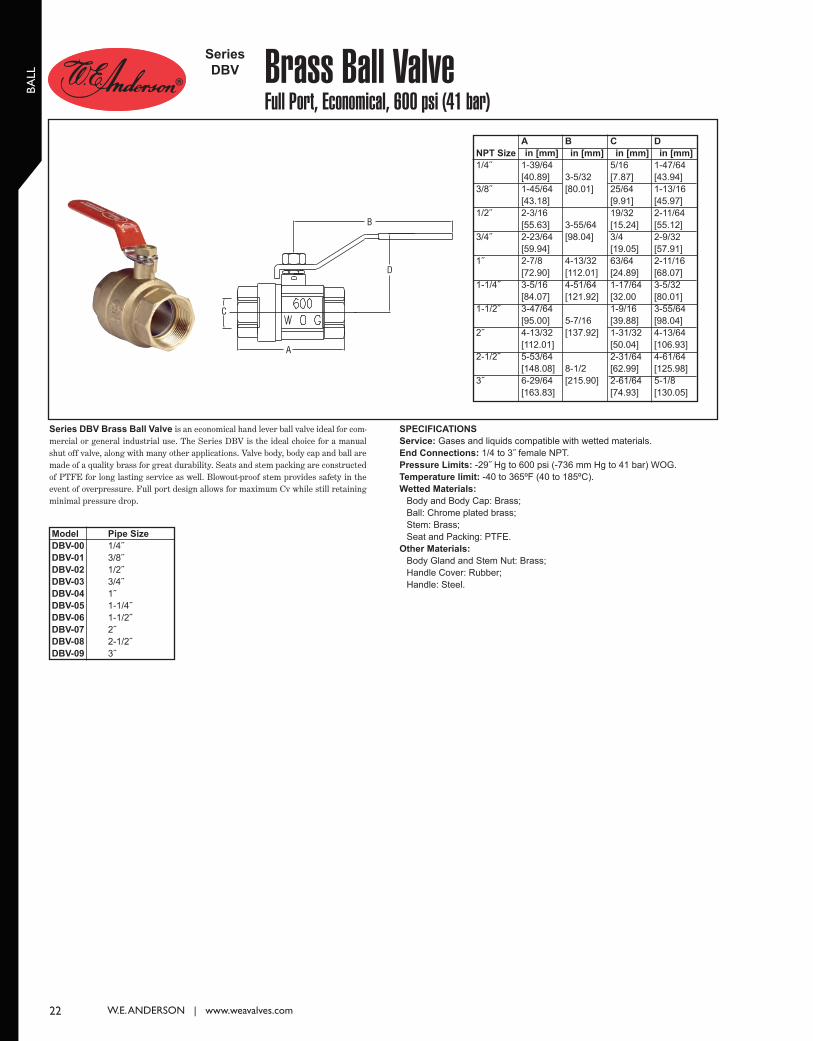
BA
LL
22 W.E. ANDERSON | www.weavalves.com
Series DBV Brass Ball Valve is an economical hand lever ball valve ideal for com-mercial or general industrial use. The Series DBV is the ideal choice for a manualshut off valve, along with many other applications. Valve body, body cap and ball aremade of a quality brass for great durability. Seats and stem packing are constructedof PTFE for long lasting service as well. Blowout-proof stem provides safety in theevent of overpressure. Full port design allows for maximum Cv while still retainingminimal pressure drop.
Brass Ball ValveFull Port, Economical, 600 psi (41 bar)
Series
DBV
SPECIFICATIONS
Service: Gases and liquids compatible with wetted materials.
End Connections: 1/4 to 3˝ female NPT.
Pressure Limits: -29˝ Hg to 600 psi (-736 mm Hg to 41 bar) WOG.
Temperature limit: -40 to 365ºF (40 to 185ºC).
Wetted Materials:
Body and Body Cap: Brass;
Ball: Chrome plated brass;
Stem: Brass;
Seat and Packing: PTFE.
Other Materials:
Body Gland and Stem Nut: Brass;
Handle Cover: Rubber;
Handle: Steel.
A
C
D
B
Model
DBV-00
DBV-01
DBV-02
DBV-03
DBV-04
DBV-05
DBV-06
DBV-07
DBV-08
DBV-09
NPT Size
1/4˝
3/8˝
1/2˝
3/4˝
1˝
1-1/4˝
1-1/2˝
2˝
2-1/2˝
3˝
A
in [mm]
1-39/64
[40.89]
1-45/64
[43.18]
2-3/16
[55.63]
2-23/64
[59.94]
2-7/8
[72.90]
3-5/16
[84.07]
3-47/64
[95.00]
4-13/32
[112.01]
5-53/64
[148.08]
6-29/64
[163.83]
B
in [mm]
3-5/32
[80.01]
3-55/64
[98.04]
4-13/32
[112.01]
4-51/64
[121.92]
5-7/16
[137.92]
8-1/2
[215.90]
C
in [mm]
5/16
[7.87]
25/64
[9.91]
19/32
[15.24]
3/4
[19.05]
63/64
[24.89]
1-17/64
[32.00
1-9/16
[39.88]
1-31/32
[50.04]
2-31/64
[62.99]
2-61/64
[74.93]
D
in [mm]
1-47/64
[43.94]
1-13/16
[45.97]
2-11/64
[55.12]
2-9/32
[57.91]
2-11/16
[68.07]
3-5/32
[80.01]
3-55/64
[98.04]
4-13/64
[106.93]
4-61/64
[125.98]
5-1/8
[130.05]
Pipe Size
1/4˝
3/8˝
1/2˝
3/4˝
1˝
1-1/4˝
1-1/2˝
2˝
2-1/2˝
3˝
022_Layout 1 1/29/14 4:05 PM Page 1
23
GLO
BE
Introduction to the Hi-Flow™ ValveThe Hi-FlowTM control valves are pneumatic operated process control valves foruse with controllers to regulate the flow of a process variable; that is steam, water,oil, gas, etc. Hi-FlowTM valves are perfect for applications in food processing, dairyproduction, HVAC, chemical/industrial processing, tire production, textileproduction, foundry operations, oil drilling rigs, automotive, and more.
Hi-FlowTM control valves were originally designed and manufactured by Taylor andare well known as a durable and dependable valve. Dwyer Instruments acquired theHi-FlowTM line in 1991 and has continued manufacturing this great quality valveunder the W.E. Anderson Division name. Dwyer Instruments offers units from stockand an exceptional lead time on made-to-order units.
FEATURES
• Wide Rangeability
This is the ability of a control valve to control from 100% of Cv down to low
values of Cv. The ratio of the high to low values for the Hi-FlowTM valve is
50:1. The Hi-FlowTM valve offers good control at extremely low flow rates,
which is particularly valuable when used on batch processes where initial
flow is high, but the flow rate is low when the control point is reached.
• Removable Seat Ring
Seat ring screws into the body of the globe valve. The seat ring can be
removed and replaced as the seat ring wears with use. Replacing the seat
ring is much more cost effective than replacing the entire globe valve body.
• High Capacity
Hi-FlowTM valves have greater flow capacity than most conventional valves
of the same size, offering the ability to use a smaller size valve that is less
expensive.
• Flow Characteristics
Linear or equal percentage.
• Selectable Fail Safe Condition
Air-to-Raise or Air-to-Lower actuators and Push-to-Open and Push-to-Close
valve bodies.
• Packing
Spring backed Teflon® V-rings to assure a tight seal on the stem.
• Exceptional Shut-Off
The Hi-FlowTM leakage rate meets ANSI/FCI 70-2 Class IV (0.01% of Cv in
the closed position).
• Adjustable Springs
Springs are adjustable in the field for proper shut-off and control range.
• Easy Maintenance
Actuators can be removed as one part from the globe valve body without
removing the valve from the line. Actuators of different sizes and actions can
be field replaced and interchanged on all valve sizes.
Used throughout this catalog, Viton® and Teflon® are registered trademarks of
E.I. du Pont de Nemours and Company; NorylTM is a trademark of General
Electric Company.
CONTACT US | U.S. 219/879-8000 | U.K. (+44) (0)1494-461707 | A.U. (+61) (0) 2 4272 2055 | China +852-23181007
023_Layout 1 1/29/14 4:06 PM Page 1
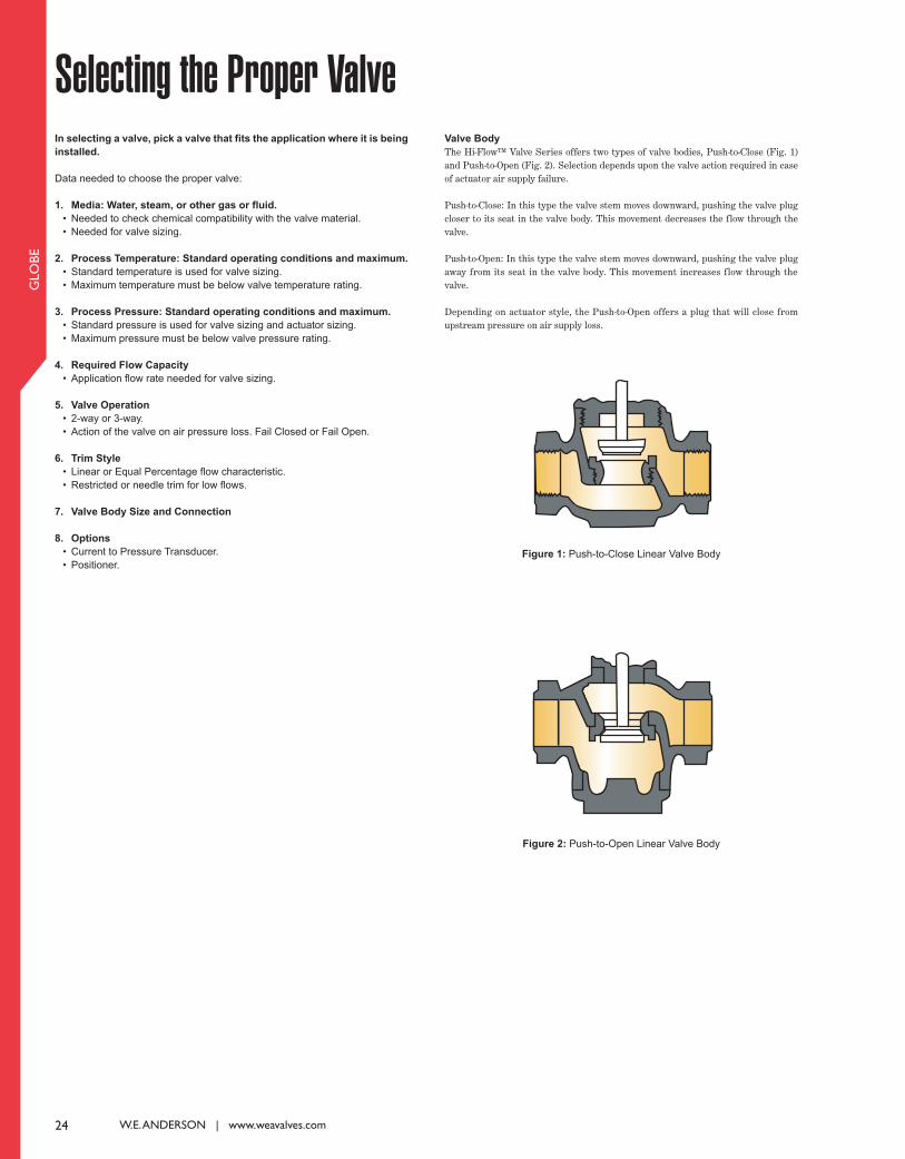
24 W.E. ANDERSON | www.weavalves.com
GLO
BE
Selecting the Proper ValveIn selecting a valve, pick a valve that fits the application where it is being
installed.
Data needed to choose the proper valve:
1. Media: Water, steam, or other gas or fluid.
• Needed to check chemical compatibility with the valve material.
• Needed for valve sizing.
2. Process Temperature: Standard operating conditions and maximum.
• Standard temperature is used for valve sizing.
• Maximum temperature must be below valve temperature rating.
3. Process Pressure: Standard operating conditions and maximum.
• Standard pressure is used for valve sizing and actuator sizing.
• Maximum pressure must be below valve pressure rating.
4. Required Flow Capacity
• Application flow rate needed for valve sizing.
5. Valve Operation
• 2-way or 3-way.
• Action of the valve on air pressure loss. Fail Closed or Fail Open.
6. Trim Style
• Linear or Equal Percentage flow characteristic.
• Restricted or needle trim for low flows.
7. Valve Body Size and Connection
8. Options
• Current to Pressure Transducer.
• Positioner.
Valve Body
The Hi-FlowTM Valve Series offers two types of valve bodies, Push-to-Close (Fig. 1)and Push-to-Open (Fig. 2). Selection depends upon the valve action required in caseof actuator air supply failure.
Push-to-Close: In this type the valve stem moves downward, pushing the valve plugcloser to its seat in the valve body. This movement decreases the flow through thevalve.
Push-to-Open: In this type the valve stem moves downward, pushing the valve plugaway from its seat in the valve body. This movement increases flow through thevalve.
Depending on actuator style, the Push-to-Open offers a plug that will close fromupstream pressure on air supply loss.
Figure 1: Push-to-Close Linear Valve Body
Figure 2: Push-to-Open Linear Valve Body
024_Layout 1 1/29/14 4:06 PM Page 1

25
GLO
BE
ActuatorsActuator Action
The Hi-FlowTM valve incorporates a Lin-E-Aire® pneumatic actuator thatautomatically controls the valve. The opening, closing and throttling of the valve plugin the valve body is accomplished by varying the air pressure to the diaphragm in theactuator.
There are two types of Lin-E-Aire® actuators; Air-to-Lower and Air-to-Raise. Theselection of the type depends upon the desired operation on loss of air supply.
Actuator Sizing
The Lin-E-Aire® actuator size and spring are selected to meet the requirements ofthe application. There are three sizes of actuators available. The actuator must besized to be large enough to shut-off the valve. The shut-off pressure is the differencebetween the inlet (upstream) and outlet (downstream) pressure when the valve isclosed. If there is no outlet pressure, then the shut-off pressure is just the maximumupstream pressure. The charts on pages 18 to 20 show example model numbers withthe maximum shut-off pressure for the three different actuator sizes. The columnlabeled MAX USP (maximum upstream pressure) is the maximum pressure that theactuator can shut-off against.
Standard operating range is 3 to 15 psig (.21 to 1.0 bar). The spring size isautomatically chosen at the factory to provide a 3 to 15 psi operating range at thecustomer provided shut-off pressure. When ordering a valve the shut-off pressuremust be given. The spring has an operating range of shut-off pressures that it willoperate, and the Lin-E-Aire® actuators have range spring adjustments for adjustingthe valve in the field. It is best to adjust the valve in the application so that it operatesat the particular shut-off pressure present.
O-RING
SPRING SEAT
RANGE SPRING
PUSH PLATEASSEMBLY
UPPER DIAPHRAGMCASING
1/4˝ NPTINPUT CONNECTION
DIAPHRAGM
LOWER DIAPHRAGMCASING
PUSH ROD
RANGE SPRINGADJUSTING SCREW
TRAVEL INDICATORPLATE
TRAVEL INDICATOR
YOKE
VALVE STEM
Air-to-Lower Actuator
Air-to-Raise Actuator
RANGE SPRINGADJUSTING SCREW
SPRING CASING
DIAPHRAGMCASING
1/4˝ NPTINPUT CONN.
DIAPHRAGM
O-RINGTRAVEL STOPCOLLARPUSH ROD
VALVE STEMTRAVEL INDICATOR
TRAVEL INDICATORPLATE
YOKEV-PACKING
PUSH PLATE
RANGE SPRING
SPRING SEAT
O-RING
CONTACT US | U.S. 219/879-8000 | U.K. (+44) (0)1494-461707 | A.U. (+61) (0) 2 4272 2055 | China +852-23181007
025_Layout 1 1/29/14 4:06 PM Page 1

26 W.E. ANDERSON | www.weavalves.com
GLO
BE
Valve OperationThe Hi-FlowTM Series is offered in 2-way and 3-way body styles. 2-way valves are used for flow control and 3-way valves are used for either mixing or diverting service. With the2-way type valve there are choices of Push-to-Open or Push-to-Close valve bodies and Air-to-Raise and Air-to-Lower actuators. The choice of the valve body and actuator dependon the desired valve action on loss of air pressure, the fail position. It is desirable that a failure in the operating air supply put the valve in the position of greatest safety for theprocess and equipment.
FLOW
SPRING
AIRDIAPHRAGM
FLOW FLOWFLOW
SPRING
AIR
DIAPHRAGM
FLOW FLOW FLOW FLOW
C
L
U
L
C U
L
C U
2-Way, Valve Action: Air-to-Open, Spring Closed (Air Off, Normal Position) “Normally Closed” or “Reverse Acting”
2-Way, Valve Action: Air-to-Close, Spring Open (Air Off, Normal Position) “Normally Open” or “Direct Acting”
3-Way
Air On Air Off
Valve Body: Push-to-Close
Actuator: Air-to-Raise
Valve Body: Push-to-Open
Actuator: Air-to-Lower
L
C U
Air On Air Off
Valve Body: Push-to-Open
Actuator: Air-to-Raise
Valve Body: Push-to-Close
Actuator: Air-to-Lower
Mixing Diverting
Air On Air Off Air On Air Off
Air On Air Off Air On Air Off
026_Layout 1 1/29/14 4:07 PM Page 1

27
GLO
BE
Trim StylesFlow Characteristic
The Hi-FlowTM valve is a control valve that is regulating the amount of flow throughthe valve. How the flow through the valve changes as the valve opens corresponds tothe trim style, or flow characteristic, of the valve. The trim style is the shape of theplug in the valve. As the valve opens, the plug shape changes the size of the valveopening, which changes the flow rate through the valve.
There are two types of trim styles, or flow characteristics available in the Hi-FlowTM
Series; Linear (Fig. 1) and Equal Percentage (Fig. 2). With Linear trim, equalincrements of plug travel provide equal increments of flow change. With EqualPercentage trim, equal increments of plug travel provide uniform percentageincrements of flow change. The correlation between plug travel and flow is shown inFigure 3. The actual flow rate by plug travel is shown on pages 14 and 15.
Choosing the optimum valve characteristic may require a detailed study of theprocess equipment and its operating conditions. However, in many applications, anyvalve will operate well and the characteristic need not be considered. Typically theseare applications were load changes are small (maximum load no greater than threetimes the minimum).
A linear valve characteristic is nearly always desirable when the major load changein the process requires merely a change in flow through the valve. Such a load changecould be a controller set point adjustment or some other load in the process itselfcalling for a new valve position. For example, when water is being heated by steamsupplied through a control valve, a change in cold water temperature or in the rateof water throughout will call for a linear valve. On the other hand, fluctuations insteam pressure call for an equal percentage valve. There is no ideal solution and theuser must decide what is best for the application.
Reduced Flow or Restricted Trim
The Hi-FlowTM Series offers restricted, a smaller port size, trim in the 3/4˝ and 1˝size valve body. This allows a reduction in the flow rate through the valve without areduction in pipe size. The 1˝ valve size is available with the 3/4˝ and 1/2˝ trim sizes,and the 3/4˝ valve size is available with the 1/2˝ trim size. The restricted trim isavailable in Linear or Equal Percentage characteristic. The flow rates are shown onpages 14 and 15.
The Hi-FlowTM Series offers needle plugs that reduce the orifice size from full portto a much smaller area size. Needle plugs are ideal for control of small flow rates andcome in Linear (Fig. 4) or Equal Percentage (Fig. 5) characteristic. Needle plugs areavailable in the 1/2˝ body sizes. Linear characteristic needle plug sizes are 3/32˝,1/16˝, and 1/32˝. Equal Percentage characteristic needle plug sizes are 3/8˝, 5/16˝,1/4˝, 3/16˝, and 1/8˝. The flow rates are shown on pages 14 and 15.
% LIFT
% F
LOW
0 10 20 30 40 50 60 70 80 90 100
20
40
60
80
100
EQUAL PERCENTAGE
LINEAR
Flow Chart
Diagram of Linear Plug
Figure 1: Push-to-Close Linear Valve Body
Figure 2: Push-to-Close Equal Percentage Valve Body
Figure 3: Inherent Flow Characteristics of Hi-FlowTM Valves
Diagram of Equal Percentage Plug
Diagram of
Linear Needle
Diagram of
Equal Percentage Needle
Figure 4: Push-to-Close
Linear Needle Plug
Figure 5: Push-to-Close
Equal Percentage
Needle Plug
CONTACT US | U.S. 219/879-8000 | U.K. (+44) (0)1494-461707 | A.U. (+61) (0) 2 4272 2055 | China +852-23181007
027_Layout 1 1/29/14 4:07 PM Page 1

GAS SERVICE
Nomenclature
Cv = Valve flow coefficient
G = Specific gravity of gas at flowing conditions
P1 = Inlet (upstream) pressure, psia
P2 = Outlet (downstream) pressure, psia
∆P = Pressure drop, P1-P2, psi
Q = Volumetric flow rate, SCFH
T = Flow temperature, in °R = (460 + °F)
psia = psig + 14.7
Formula: Cv =
If pressure drop is greater than 50%, ∆P > P1/2, use:
Cv =
Example:
Medium: Nitrogen
Specific Gravity: 0.966
Flow Rate: 10,000 SCFH
P1 = 100 psig: 100 + 14.7 = 114.7 psia
P2 = 95 psig: 95 + 14.7 = 109.7 psia
Pressure Drop: 5 psi
Temperature 70°F: 70 + 460 = 530°R
Needed Valve Cv:
Cv = = 7.01
Q G x T
750 P1
28 W.E. ANDERSON | www.weavalves.com
GLO
BE
Valve Sizing
LIQUID SERVICE
Nomenclature
Cv = Valve flow coefficient
g = Specific gravity of liquid at flowing conditions
P1 = Inlet (upstream) pressure, psia
P2 = Outlet (downstream) pressure, psia
∆P = Pressure drop, P1-P2, psi
Q = Volumetric flow rate, US GPM
For liquid service, the pressure drop, ∆P, must not exceed 50% of P1 to avoid
cavitation damage.
Formula: Cv = Q
Example 1:
Medium: Water
Specific Gravity: 1.0
Flow Rate: 100 GPM
Pressure Drop: 5 psi
Needed Valve Cv:
Cv = 100 = 44.72
Example 2:
Medium: Water
Specific Gravity: 1.0
Flow Rate: 110 GPM
Valve Cv: 50.3
Pressure Drop:
∆P = = = 4.78 psi(
It is essential to correctly size a control valve for the application. The valve will not control the process effectively or efficiently if it is sized incorrectly. A control valve shouldalways be sized according to the flow requirement, not the line size. A valve that is too oversized will result in poor controllability of the process. The system will fluctuate andcycle from the lack of control. A valve that is undersized will result in having to take a larger pressure drop across the valve to achieve needed flow. The system will lose morepressure making the pump work harder.
All control valves have a rated flow capacity expressed as the Cv rating. Cv, is the valve flow coefficient and is the number of U.S. gallons per minute of 60°F water that will passthrough a fully open valve with a 1 psi pressure drop. For example, a Hi-FlowTM valve with a Cv rating of 10.75 will pass 10.75 GPM of water with a pressure drop of 1 psi. Thehigher the Cv, the higher the flow capacity of the valve.
To select the proper valve for the application it is necessary to calculate the needed flow capacity, or Cv. The necessary Cv for the application will be dependent upon the pressuredrop across the valve. Pressure drop is the difference between the inlet and outlet pressure at full flow when the valve is fully open. The greater the pressure drop taken acrossthe valve, the greater the flow through the valve. Design engineers try to keep the pressure drop as low as possible, but the valve, needs pressure drop to control the process.
Once the required Cv is determined, selection of the proper size control valve can be obtained by comparing the required Cv to the Cv values for the Hi-FlowTM valves. To size thevalve properly, it is best to increase the required Cv at maximum flow by 10 to 15% to account for different operating conditions. Also, the minimum required controllable flowshould fall within the rangeability of the valve. The rangeability of Hi-FlowTM valves is 50:1. For example, if a Hi-FlowTM valve was chosen with a Cv of 10.75, the minimumcontrollable Cv would be 10.75 divided by 50, or 0.215.
To calculate the required Cv for the application, use the following equations according to the process medium:
g
∆P
1.0
5
Q2
Cv) ( 1102
50.3)
Q
963
G x T
∆P (P1 + P2)
10,000
963
(.966) x (530)
(5) x (114.7 + 109.7)
028_Layout 1 1/29/14 4:07 PM Page 1
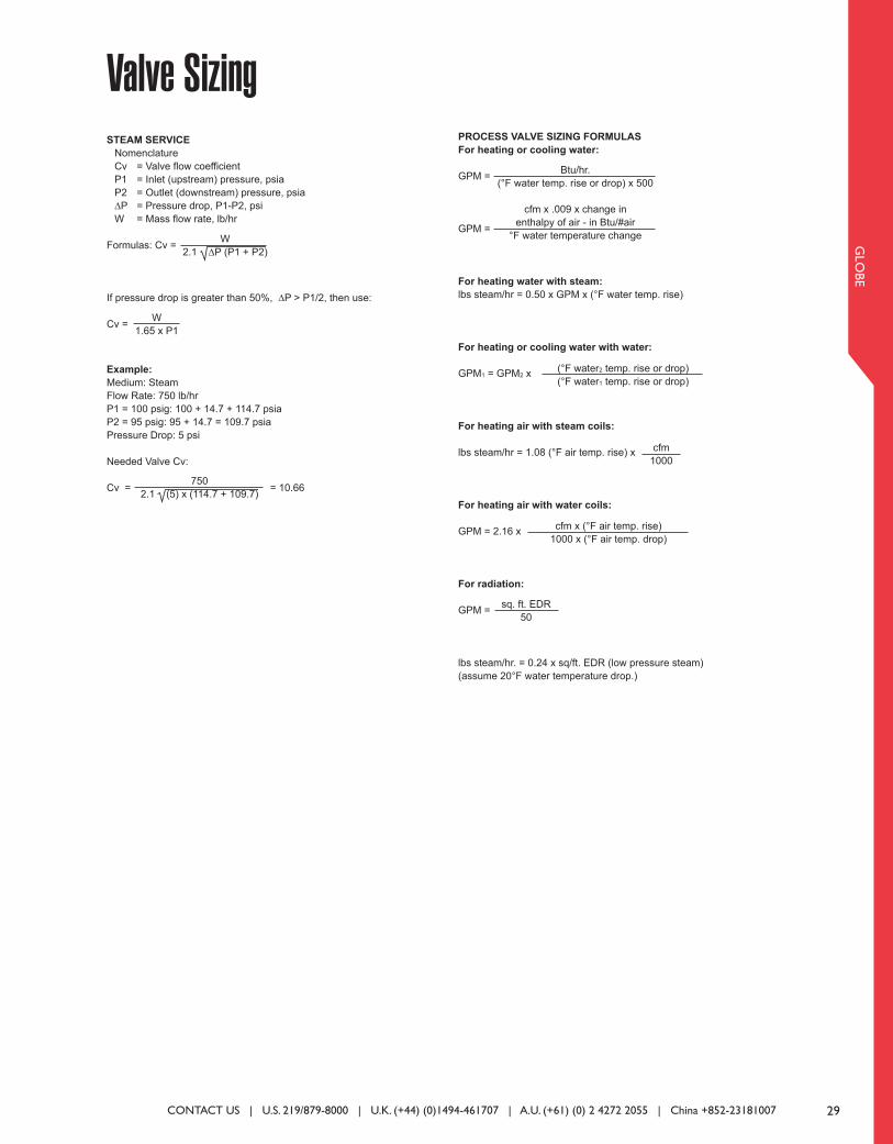
29
GLO
BE
Valve SizingSTEAM SERVICE
Nomenclature
Cv = Valve flow coefficient
P1 = Inlet (upstream) pressure, psia
P2 = Outlet (downstream) pressure, psia
∆P = Pressure drop, P1-P2, psi
W = Mass flow rate, lb/hr
Formulas: Cv =
If pressure drop is greater than 50%, ∆P > P1/2, then use:
Cv =
Example:
Medium: Steam
Flow Rate: 750 lb/hr
P1 = 100 psig: 100 + 14.7 + 114.7 psia
P2 = 95 psig: 95 + 14.7 = 109.7 psia
Pressure Drop: 5 psi
Needed Valve Cv:
Cv = = 10.66
W
2.1 ∆P (P1 + P2)
W
1.65 x P1
750
2.1 (5) x (114.7 + 109.7)
PROCESS VALVE SIZING FORMULAS
For heating or cooling water:
GPM =
GPM =
For heating water with steam:
lbs steam/hr = 0.50 x GPM x (°F water temp. rise)
For heating or cooling water with water:
GPM1 = GPM2 x
For heating air with steam coils:
lbs steam/hr = 1.08 (°F air temp. rise) x
For heating air with water coils:
GPM = 2.16 x
For radiation:
GPM =
lbs steam/hr. = 0.24 x sq/ft. EDR (low pressure steam)
(assume 20°F water temperature drop.)
sq. ft. EDR
50
Btu/hr.
(°F water temp. rise or drop) x 500
cfm x .009 x change in
enthalpy of air - in Btu/#air
°F water temperature change
(°F water2 temp. rise or drop)
(°F water1 temp. rise or drop)
cfm
1000
cfm x (°F air temp. rise)
1000 x (°F air temp. drop)
CONTACT US | U.S. 219/879-8000 | U.K. (+44) (0)1494-461707 | A.U. (+61) (0) 2 4272 2055 | China +852-23181007
029_Layout 1 1/29/14 4:07 PM Page 1
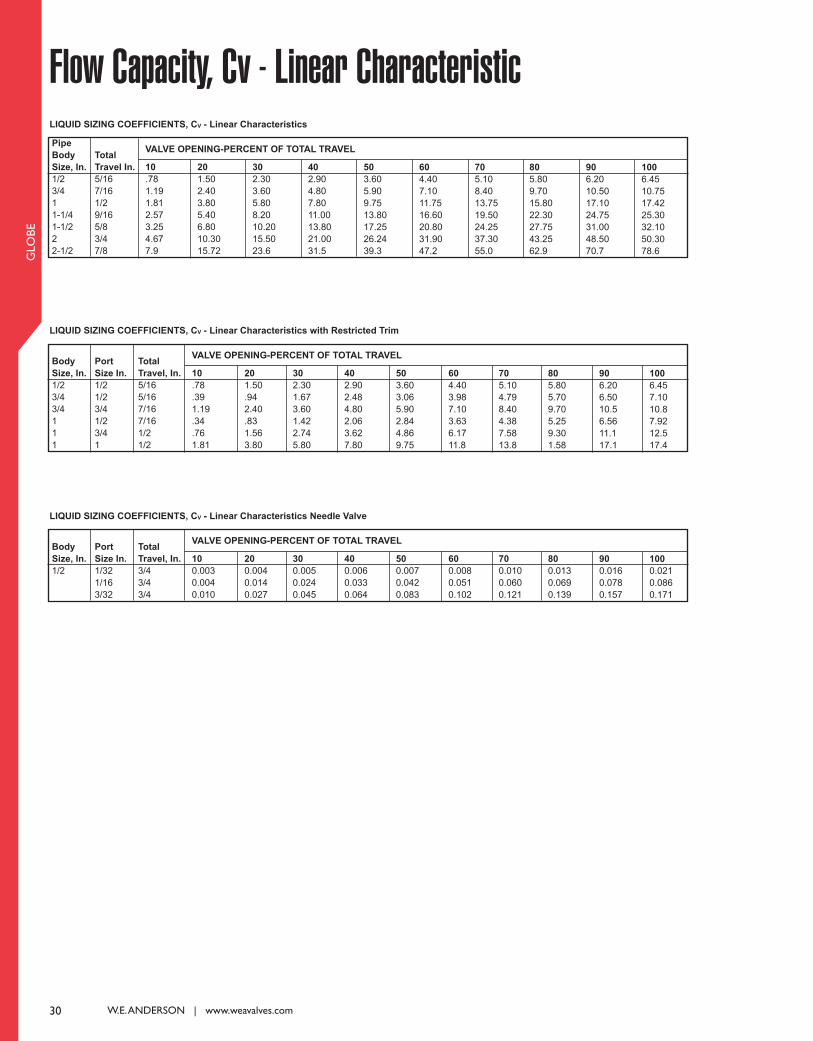
30 W.E. ANDERSON | www.weavalves.com
GLO
BE
Pipe
Body
Size, In.
1/2
3/4
1
1-1/4
1-1/2
2
2-1/2
Total
Travel In.
5/16
7/16
1/2
9/16
5/8
3/4
7/8
10
.78
1.19
1.81
2.57
3.25
4.67
7.9
20
1.50
2.40
3.80
5.40
6.80
10.30
15.72
30
2.30
3.60
5.80
8.20
10.20
15.50
23.6
40
2.90
4.80
7.80
11.00
13.80
21.00
31.5
50
3.60
5.90
9.75
13.80
17.25
26.24
39.3
60
4.40
7.10
11.75
16.60
20.80
31.90
47.2
70
5.10
8.40
13.75
19.50
24.25
37.30
55.0
80
5.80
9.70
15.80
22.30
27.75
43.25
62.9
90
6.20
10.50
17.10
24.75
31.00
48.50
70.7
100
6.45
10.75
17.42
25.30
32.10
50.30
78.6
VALVE OPENING-PERCENT OF TOTAL TRAVEL
LIQUID SIZING COEFFICIENTS, CV - Linear Characteristics
Flow Capacity, Cv - Linear Characteristic
Body
Size, In.
1/2
3/4
3/4
1
1
1
Port
Size In.
1/2
1/2
3/4
1/2
3/4
1
10
.78
.39
1.19
.34
.76
1.81
20
1.50
.94
2.40
.83
1.56
3.80
30
2.30
1.67
3.60
1.42
2.74
5.80
40
2.90
2.48
4.80
2.06
3.62
7.80
50
3.60
3.06
5.90
2.84
4.86
9.75
60
4.40
3.98
7.10
3.63
6.17
11.8
70
5.10
4.79
8.40
4.38
7.58
13.8
80
5.80
5.70
9.70
5.25
9.30
1.58
90
6.20
6.50
10.5
6.56
11.1
17.1
100
6.45
7.10
10.8
7.92
12.5
17.4
VALVE OPENING-PERCENT OF TOTAL TRAVEL
LIQUID SIZING COEFFICIENTS, CV - Linear Characteristics with Restricted Trim
Total
Travel, In.
5/16
5/16
7/16
7/16
1/2
1/2
Body
Size, In.
1/2
Port
Size In.
1/32
1/16
3/32
10
0.003
0.004
0.010
20
0.004
0.014
0.027
30
0.005
0.024
0.045
40
0.006
0.033
0.064
50
0.007
0.042
0.083
60
0.008
0.051
0.102
70
0.010
0.060
0.121
80
0.013
0.069
0.139
90
0.016
0.078
0.157
100
0.021
0.086
0.171
VALVE OPENING-PERCENT OF TOTAL TRAVEL
LIQUID SIZING COEFFICIENTS, CV - Linear Characteristics Needle Valve
Total
Travel, In.
3/4
3/4
3/4
030_Layout 1 1/29/14 4:09 PM Page 1
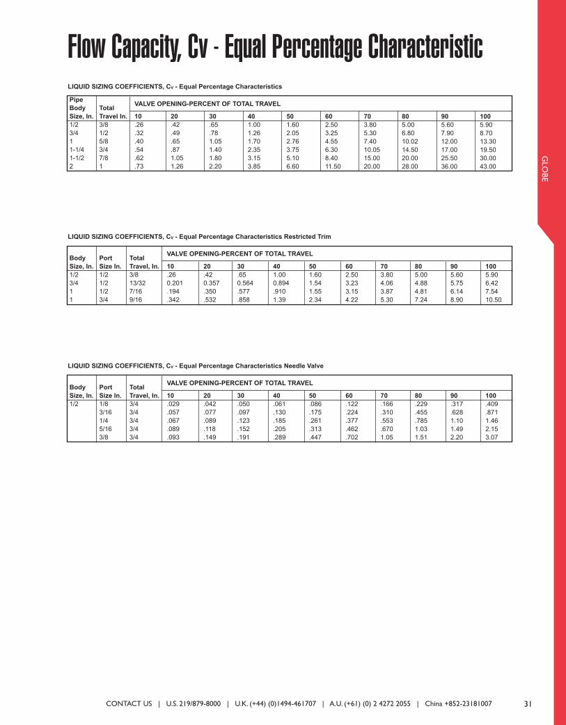
31
GLO
BE
Flow Capacity, Cv - Equal Percentage CharacteristicPipe
Body
Size, In.
1/2
3/4
1
1-1/4
1-1/2
2
Total
Travel In.
3/8
1/2
5/8
3/4
7/8
1
10
.26
.32
.40
.54
.62
.73
20
.42
.49
.65
.87
1.05
1.26
30
.65
.78
1.05
1.40
1.80
2.20
40
1.00
1.26
1.70
2.35
3.15
3.85
50
1.60
2.05
2.76
3.75
5.10
6.60
60
2.50
3.25
4.55
6.30
8.40
11.50
70
3.80
5.30
7.40
10.05
15.00
20.00
80
5.00
6.80
10.02
14.50
20.00
28.00
90
5.60
7.90
12.00
17.00
25.50
36.00
100
5.90
8.70
13.30
19.50
30.00
43.00
VALVE OPENING-PERCENT OF TOTAL TRAVEL
LIQUID SIZING COEFFICIENTS, CV - Equal Percentage Characteristics
Body
Size, In.
1/2
3/4
1
1
Port
Size In.
1/2
1/2
1/2
3/4
10
.26
0.201
.194
.342
20
.42
0.357
.350
.532
30
.65
0.564
.577
.858
40
1.00
0.894
.910
1.39
50
1.60
1.54
1.55
2.34
60
2.50
3.23
3.15
4.22
70
3.80
4.06
3.87
5.30
80
5.00
4.88
4.81
7.24
90
5.60
5.75
6.14
8.90
100
5.90
6.42
7.54
10.50
VALVE OPENING-PERCENT OF TOTAL TRAVEL
LIQUID SIZING COEFFICIENTS, CV - Equal Percentage Characteristics Restricted Trim
Total
Travel, In.
3/8
13/32
7/16
9/16
Body
Size, In.
1/2
Port
Size In.
1/8
3/16
1/4
5/16
3/8
10
.029
.057
.067
.089
.093
20
.042
.077
.089
.118
.149
30
.050
.097
.123
.152
.191
40
.061
.130
.185
.205
.289
50
.086
.175
.261
.313
.447
60
.122
.224
.377
.462
.702
70
.166
.310
.553
.670
1.05
80
.229
.455
.785
1.03
1.51
90
.317
.628
1.10
1.49
2.20
100
.409
.871
1.46
2.15
3.07
VALVE OPENING-PERCENT OF TOTAL TRAVEL
LIQUID SIZING COEFFICIENTS, CV - Equal Percentage Characteristics Needle Valve
Total
Travel, In.
3/4
3/4
3/4
3/4
3/4
CONTACT US | U.S. 219/879-8000 | U.K. (+44) (0)1494-461707 | A.U. (+61) (0) 2 4272 2055 | China +852-23181007
031_Layout 1 1/29/14 4:09 PM Page 1
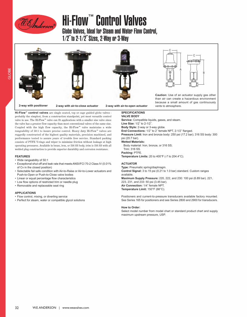
32 W.E. ANDERSON | www.weavalves.com
GLO
BE
Hi-Flow™ Control Valves Globe Valves, Ideal for Steam and Water Flow Control,1/2˝ to 2-1/2˝ Sizes, 2-Way or 3-Way
Hi-Flow™ control valves are single seated, top or cage guided globe valves -probably the simplest, from a construction standpoint, yet most versatile controlvalve in use. The Hi-Flow™ valve can fit applications with a smaller size valve sincethe valve has a greater flow capacity than most conventional valves of the same size.Coupled with the high flow capacity, the Hi-Flow™ valve maintains a widerangeability of 50:1 to insure precise control. Heavy duty Hi-Flow™ valves areruggedly constructed of the highest quality materials, precision machined, andperformance tested to assure years of trouble free service. Standard packingconsists of PTFE V-rings and wiper to minimize friction without leakage at highoperating pressures. Available in brass, iron, or 316 SS body, trim is 316 SS with allwelded plug construction to provide superior durability and corrosion resistance.
FEATurES
• Wide rangeability of 50:1
• Exceptional shut-off and leak rate that meets ANSI/FCI 70-2 Class IV (0.01%
of Cv in the closed position)
• Selectable fail safe condition with Air-to-Raise or Air-to-Lower actuators and
Push-to-Open or Push-to-Close valve bodies
• Linear or equal percentage flow characteristics
• Low flow options of restricted trim or needle plug
• Removable and replaceable seat ring
APPlICATIONS
• Flow control, mixing, or diverting service
• Perfect for steam, water or compatible glycol solutions
SPECIFICATIONS
VAlVE BOdy
Service: Compatible liquids, gases, and steam.
line Size: 1/2˝ to 2-1/2˝.
Body Style: 2-way or 3-way globe.
End Connections: 1/2˝ to 2˝ female NPT, 2-1/2˝ flanged.
Pressure limit: Iron and bronze body: 250 psi (17.2 bar); 316 SS body: 300
psi (20.7 bar).
Wetted Materials:
Body material: Iron, bronze, or 316 SS;
Trim: 316 SS.
Packing: PTFE.
Temperature limits: 20 to 400°F (-7 to 204.4°C).
ACTuATOr
Type: Pneumatic spring/diaphragm.
Control Signal: 3 to 15 psi (0.21 to 1.0 bar) standard. Custom ranges
available.
Maximum Supply Pressure: 220, 222, and 230: 100 psi (6.89 bar). 221,
223, 231, and 233: 50 psi (3.45 bar).
Air Connection: 1/4˝ female NPT.
Temperature limit: 150°F (66°C).
Positioners and current-to-pressure transducers available factory mounted.
See Series 165 for positioners and see Series 2800 and 2900 for transducers.
How to Order:
Select model number from model chart or standard product chart and supply
maximum upstream pressure, USP.
2-way with air-to-open actuator2-way with positioner
Caution: Use of an actuator supply gas other
than air can create a hazardous environment
because a small amount of gas continuously
vents to atmosphere.
C
C
BA
2-way with air-to-close actuator
032_Layout 1 1/29/14 4:09 PM Page 1

33
GLO
BE
Example
Configuration
Valve Body Action
Connection Size
Valve Seat
Valve Plug Type
Valve Body Material
Trim Material
Actuator
Needle Plug Port Size
Options
2
2
3
00
00
01
1
0
1
2
3
4
5
6
V
V
W
A
A
L
S
N
3
1
3
4
2
2
230
220
221
222
223
230
231
233
2
3
4
5
6
7
8
9
L0
A
L0
L1
Z
LRF
HRF
2001VA32-230-LO Hi-Flow™ Globe Valve; 2-way, 3/4˝ NPT connection, linear plug, bronze body, 316
SS trim, reduced port 1/2˝ size.
2-way
3-way
Push-To-Close
Push-To-Open (2-way only)
1/2˝ NPT
3/4˝ NPT
1˝ NPT
1-1/4˝ NPT
1-1/2˝ NPT (or Flange with LRF option)
2˝ NPT (or Flange with LRF option)
2-1/2˝ Flange (see options)
Single Seat (2-way only)
Double Seat (3-way only)
Linear
Linear Needle (2000 only)
Equal Percentage (2000 to 2002 only)
Equal Percentage Needle (2000 only)
Ductile Iron
Bronze
316 SS
316 SS
Air-To-Lower, 20 in2
Air-To-Lower, 45 in2
Air-To-Lower, 45 in2
Air-To-Lower, 80 in2
Air-To-Raise, 20 in2 (2-way only)
Air-To-Raise, 45 in2 (2-way only)
Air-To-Raise, 80 in2 (2-way only)
1/8˝ for Type N valve plug
3/16˝ for Type N valve plug
1/4˝ for Type N valve plug
5/16˝ for Type N valve plug
3/8˝ for Type N valve plug
1/32˝ for Type L valve plug
1/16˝ for Type L valve plug
2/32˝ for Type L valve plug
Positioner factory mounted (specify positioner model)
Reduced port: 3/4˝ to 1/2˝ port size (2001 only)
Reduced port: 1˝ to 1/2˝ port size (2002 only)
Reduced port: 1˝ to 3/4˝ port size (2002 only)
Special operating range (2-10 psi, 10-18 psi)
Low Range Flange: Class 125 in Iron or Class 150 Bronze, 316 SS body
(for 1-1/2˝ and 2˝ sizes only, standard on 2-1/2˝ size)
High Range Flange: Class 250 in Iron or Class 300 in Bronze, 316 SS body
(for 1-1/2˝ to 2-1/2˝ sizes)
Hi-Flow™ Control Valves Model Chart
CONTACT US | U.S. 219/879-8000 | U.K. (+44) (0)1494-461707 | A.U. (+61) (0) 2 4272 2055 | China +852-23181007
033_Layout 1 1/29/14 4:10 PM Page 1

34 W.E. ANDERSON | www.weavalves.com
GLO
BE
Control Valves – Hi-Flow™ Series2-Way Simplified Selection Guide with Standard Products
Caution: Use of an actuator supply gas other than air can
create a hazardous environment because a small amount of
gas continuously vents to atmosphere.
C
C
B
A
Use the chart to aid in the selection of Hi-Flow™ Control Valve.
As long as the maximum upstream pressure (USP) is less
than, or equal to, the value listed, the model shown can be
manufactured and calibrated to your specific requirements.
Specify maximum upstream pressure, USP, when ordering.
Pipe
Size
1/2˝
3/4˝
1˝
1-1/4˝
1-1/2˝
2˝
*2-1/2˝
Cv
100%
6.45
10.75
17.42
25.30
32.10
50.30
78.60
Body
Material
Bronze
316SS
Bronze
316SS
Bronze
316SS
Bronze
316SS
Bronze
316SS
Bronze
316SS
Iron
Bronze
316SS
Model Number
(Air-To-Open)
2000VA32-230
2000VA42-230
2001VA32-230
2001VA32-231
2001VA42-230
2001VA42-231
2002VA32-230
2002VA32-231
2002VA42-230
2002VA42-231
2003VA32-230
2003VA32-231
2003VA32-233
2003VA42-230
2003VA42-231
2003VA42-233
2004VA32-230
2004VA32-231
2004VA32-233
2004VA42-230
2004VA42-231
2004VA42-233
2005VA32-230
2005VA32-231
2005VA32-233
2005VA42-230
2005VA42-231
2005VA42-233
2006VA12-233
2006VA32-233
2006VA42-233
* Valve has flanged connections. Max. USP (PSI) is for Linear Valves.
Consult factory for optional trim.
Max. USP
psi (bar)
3-15 (.21-1.0)
250 (17.2)
300 (20.7)
250 (17.2)
250 (17.2)
285 (19.7)
300 (20.7)
166 (11.4)
250 (17.2)
166 (11.4)
300 (20.7)
98 (6.8)
245 (16.9)
250 (17.2)
98 (6.8)
245 (16.9)
300 (20.7)
65 (4.5)
168 (11.6)
250 (17.2)
65 (4.5)
168 (11.6)
300 (20.7)
31 (2.1)
88 (6.1)
175 (12.1)
31 (2.1)
88 (6.1)
175 (12.1)
105 (7.2)
105 (7.2)
105 (7.2)
A
in (mm)
19-3/4 (501.7)
19-3/4 (501.7)
19-3/4 (501.7)
20-3/8 (517.5)
19-3/4 (501.7)
20-3/8 (517.5)
20-3/16 (512.8)
20-13/16 (528.6)
20-3/16 (512.8)
20-13/16 (528.6)
20-5/16 (515.9)
20-15/16 (531.8)
25-13/32 (645.3)
20-5/16 (515.9)
20-15/16 (531.8)
25-13/32 (645.3)
20-11/16 (525.5)
21-5/16 (541.3)
25-25/32 (654.8)
20-11/16 (525.5)
21-5/16 (541.3)
25-25/32 (654.8)
20-15/16 (531.8)
21-9/16 (547.7)
26-1/32 (661.2)
20-15/16 (531.8)
21-9/16 (547.7)
26-1/32 (661.2)
26-1/4 (666.8)
26-1/4 (666.8)
26-1/4 (666.8)
C
in (mm)
7-3/4 (196.9)
7-3/4 (196.9)
7-3/4 (196.9)
10-5/8 (269.9)
7-3/4 (196.9)
10-5/8 (269.9)
7-3/4 (196.9)
10-5/8 (269.9)
7-3/4 (196.9)
10-5/8 (269.9)
7-3/4 (196.9)
10-5/8 (269.9)
13-3/8 (339.7)
7-3/4 (196.9)
10-5/8 (269.9)
13-3/8 (339.7)
7-3/4 (196.9)
10-5/8 (269.9)
13-3/8 (339.7)
7-3/4 (196.9)
10-5/8 (269.9)
13-3/8 (339.7)
7-3/4 (196.9)
10-5/8 (269.9)
13-3/8 (339.7)
7-3/4 (196.9)
10-5/8 (269.9)
13-3/8 (339.7)
13-3/8 (339.7)
13-3/8 (339.7)
13-3/8 (339.7)
034_Layout 1 1/29/14 4:10 PM Page 1
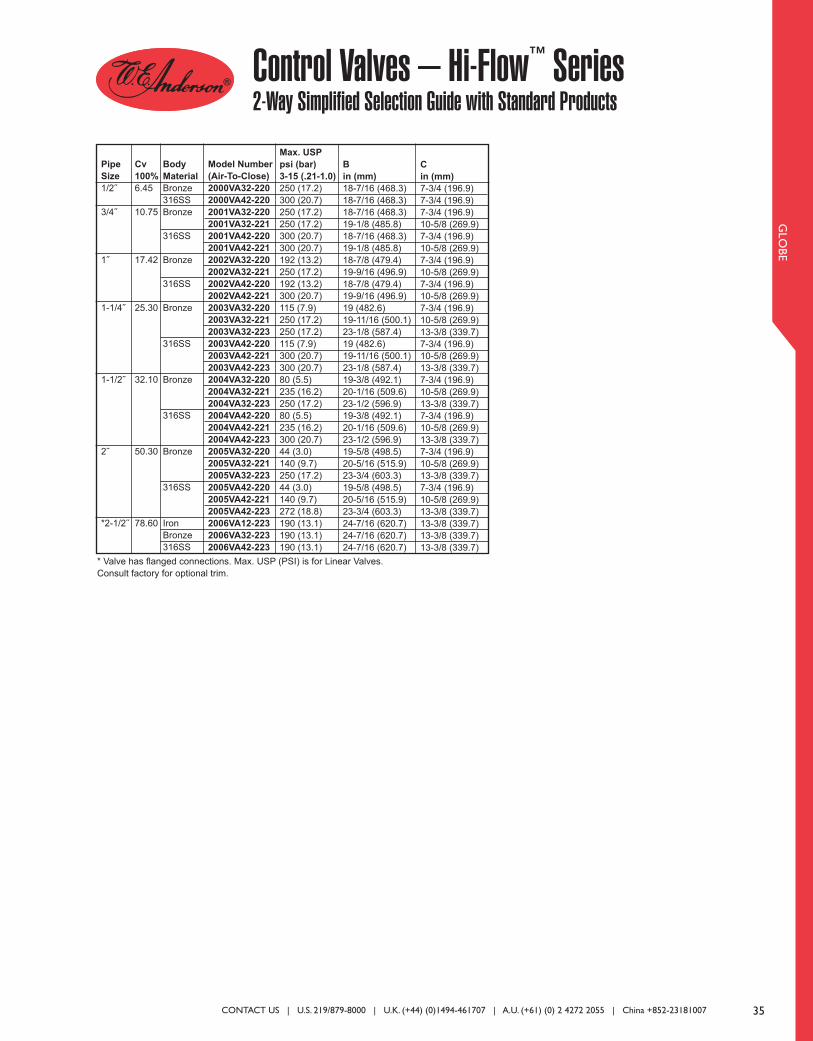
35
GLO
BE
Control Valves – Hi-Flow™ Series2-Way Simplified Selection Guide with Standard Products
Pipe
Size
1/2˝
3/4˝
1˝
1-1/4˝
1-1/2˝
2˝
*2-1/2˝
Cv
100%
6.45
10.75
17.42
25.30
32.10
50.30
78.60
Body
Material
Bronze
316SS
Bronze
316SS
Bronze
316SS
Bronze
316SS
Bronze
316SS
Bronze
316SS
Iron
Bronze
316SS
Model Number
(Air-To-Close)
2000VA32-220
2000VA42-220
2001VA32-220
2001VA32-221
2001VA42-220
2001VA42-221
2002VA32-220
2002VA32-221
2002VA42-220
2002VA42-221
2003VA32-220
2003VA32-221
2003VA32-223
2003VA42-220
2003VA42-221
2003VA42-223
2004VA32-220
2004VA32-221
2004VA32-223
2004VA42-220
2004VA42-221
2004VA42-223
2005VA32-220
2005VA32-221
2005VA32-223
2005VA42-220
2005VA42-221
2005VA42-223
2006VA12-223
2006VA32-223
2006VA42-223
* Valve has flanged connections. Max. USP (PSI) is for Linear Valves.
Consult factory for optional trim.
Max. USP
psi (bar)
3-15 (.21-1.0)
250 (17.2)
300 (20.7)
250 (17.2)
250 (17.2)
300 (20.7)
300 (20.7)
192 (13.2)
250 (17.2)
192 (13.2)
300 (20.7)
115 (7.9)
250 (17.2)
250 (17.2)
115 (7.9)
300 (20.7)
300 (20.7)
80 (5.5)
235 (16.2)
250 (17.2)
80 (5.5)
235 (16.2)
300 (20.7)
44 (3.0)
140 (9.7)
250 (17.2)
44 (3.0)
140 (9.7)
272 (18.8)
190 (13.1)
190 (13.1)
190 (13.1)
B
in (mm)
18-7/16 (468.3)
18-7/16 (468.3)
18-7/16 (468.3)
19-1/8 (485.8)
18-7/16 (468.3)
19-1/8 (485.8)
18-7/8 (479.4)
19-9/16 (496.9)
18-7/8 (479.4)
19-9/16 (496.9)
19 (482.6)
19-11/16 (500.1)
23-1/8 (587.4)
19 (482.6)
19-11/16 (500.1)
23-1/8 (587.4)
19-3/8 (492.1)
20-1/16 (509.6)
23-1/2 (596.9)
19-3/8 (492.1)
20-1/16 (509.6)
23-1/2 (596.9)
19-5/8 (498.5)
20-5/16 (515.9)
23-3/4 (603.3)
19-5/8 (498.5)
20-5/16 (515.9)
23-3/4 (603.3)
24-7/16 (620.7)
24-7/16 (620.7)
24-7/16 (620.7)
C
in (mm)
7-3/4 (196.9)
7-3/4 (196.9)
7-3/4 (196.9)
10-5/8 (269.9)
7-3/4 (196.9)
10-5/8 (269.9)
7-3/4 (196.9)
10-5/8 (269.9)
7-3/4 (196.9)
10-5/8 (269.9)
7-3/4 (196.9)
10-5/8 (269.9)
13-3/8 (339.7)
7-3/4 (196.9)
10-5/8 (269.9)
13-3/8 (339.7)
7-3/4 (196.9)
10-5/8 (269.9)
13-3/8 (339.7)
7-3/4 (196.9)
10-5/8 (269.9)
13-3/8 (339.7)
7-3/4 (196.9)
10-5/8 (269.9)
13-3/8 (339.7)
7-3/4 (196.9)
10-5/8 (269.9)
13-3/8 (339.7)
13-3/8 (339.7)
13-3/8 (339.7)
13-3/8 (339.7)
CONTACT US | U.S. 219/879-8000 | U.K. (+44) (0)1494-461707 | A.U. (+61) (0) 2 4272 2055 | China +852-23181007
035_Layout 1 1/29/14 4:10 PM Page 1

36 W.E. ANDERSON | www.weavalves.com
GLO
BE
Use the chart to aid in the selection of the most economical Hi-
Flow™ 3-Way Control Valve for your application. Specify
maximum upstream pressures (USP’s); Mixing: USPU and
USPL; Diverting: USPC; based on standard 3-15 psi (.21-1.0 bar)
pneumatic control signal.
Control Valves - Hi-Flow™ Series3-Way Standard Products for Mixing or Diverting
For diverting service, add USPU and USPC to determine the
shutoff pressure. For mixing service compute: (USPU - USPC)
+ (USPL - USPC) to determine the shutoff pressure.
Dimension Data
MIXING SERVICE:
FLOW IN - ports U&L
FLOW OUT - port C
DIVERTING SERVICE:
FLOW IN - port C
FLOW OUT - ports U&L
Standard Models include LIN-E-AIRE® Air-To-Lower Actuator
- port L opens on loss of Air
B
in (mm)
2-9/16 (65.1)
2-9/16 (65.1)
3 (76.2)
3-3/16 (81.0)
3-3/4 (95.3)
3-15/16 (100.0)
Pipe
Size
1/2˝
3/4˝
1˝
1-1/4˝
1-1/2˝
2˝
Caution: Use of an actuator supply gas other than air can
create a hazardous environment because a small amount of
gas continuously vents to atmosphere.
Pipe
Size
1/2˝
3/4˝
1˝
1-1/4˝
1-1/2˝
2˝
*2-1/2˝
Cv
100%
6.45
10.75
17.42
25.30
32.10
50.30
78.60
Body
Material
Bronze
316SS
Bronze
316SS
Bronze
316SS
Bronze
316SS
Bronze
316SS
Bronze
316SS
Iron
Bronze
316SS
Model
Number
3000WA32-220
3000WA42-220
3001WA32-220
3001WA42-220
3002WA32-220
3002WA32-221
3002WA42-220
3002WA42-221
3003WA32-220
3003WA32-221
3003WA42-220
3003WA42-221
3004WA32-220
3004WA32-221
3004WA32-223
3004WA42-220
3004WA42-221
3004WA42-223
3005WA32-220
3005WA32-221
3005WA32-223
3005WA42-220
3005WA42-221
3005WA42-223
3006WA12-223
3006WA32-223
3006WA42-223
* Valve has flanged connections. Max. USP (PSI) is for Linear Valves.
Consult factory for optional trim.
USP (s)
psi (bar)
250 (17.2)
300 (20.7)
250 (17.2)
300 (20.7)
200 (13.8)
250 (17.2)
200 (13.8)
300 (20.7)
120 (8.4)
250 (17.2)
120 (8.4)
300 (20.7)
80 (5.6)
200 (13.8)
250 (17.2)
80 (5.5)
200 (13.8)
300 (20.7)
45 (3.1)
100 (6.9)
175 (12.1)
45 (3.1)
100 (6.9)
175 (12.1)
97 (6.7)
97 (6.7)
97 (6.7)
E
in (mm)
18-1/16 (458.8)
18-1/16 (458.8)
18-1/16 (458.8)
18-1/16 (458.8)
18-5/16 (465.1)
19 (482.6)
18-5/16 (465.1)
19 (482.6)
18-3/8 (466.7)
19-1/16 (484.2)
18-3/8 (466.7)
19-1/16 (484.2)
18-5/8 (473.1)
19-5/16 (490.5)
21-3/8 (542.9)
18-5/8 (473.1)
19-5/16 (490.5)
21-3/8 (542.9)
19-1/16 (484.2)
19-3/4 (501.7)
21-13/16 (554.0)
19-1/16 (484.2)
19-3/4 (501.7)
21-13/16 (554.0)
24.52 (622.8)
24.52 (622.8)
24.52 (622.8)
F
in (mm)
7-3/4 (196.9)
7-3/4 (196.9)
7-3/4 (196.9)
7-3/4 (196.9)
7-3/4 (196.9)
10-5/8 (269.9)
7-3/4 (196.9)
10-5/8 (269.9)
7-3/4 (196.9)
10-5/8 (269.9)
7-3/4 (196.9)
10-5/8 (269.9)
7-3/4 (196.9)
10-5/8 (269.9)
13-3/8 (339.7)
7-3/4 (196.9)
10-5/8 (269.9)
13-3/8 (339.7)
7-3/4 (196.9)
10-5/8 (269.9)
13-3/8 (339.7)
7-3/4 (196.9)
10-5/8 (269.9)
13-3/8 (339.7)
13-3/8 (339.7)
13-3/8 (339.7)
13-3/8 (339.7)
C
in (mm)
2-3/16 (55.6)
2-3/16 (55.6)
2-7/16 (61.9)
2-1/2 (63.5)
2-3/4 (69.9)
3-3/16 (81.0)
D
in (mm)
4-1/8 (104.8)
4-1/8 (104.8)
4 (101.6)
3-3/4 (95.3)
3-11/16 (93.7)
3-11/16 (93.7)
036_Layout 1 1/29/14 4:10 PM Page 1
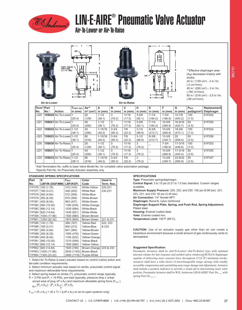
37
GLO
BE
SPECIFICATIONS
Type: Pneumatic spring/diaphragm.
Control Signal: 3 to 15 psi (0.21 to 1.0 bar) standard. Custom ranges
available.
Maximum Supply Pressure: 220, 222, and 230: 100 psi (6.89 bar). 221,
223, 231, and 233: 50 psi (3.45 bar).
Air Connection: 1/4˝ female NPT.
Diaphragm: Buna-N, nylon reinforced.
Diaphragm Support Plate, Spring, and Push Rod, Spring Adjustment:
Plated steel.
Housing: Enamel coated steel.
Yoke: Enamel coated iron.
Temperature Limit: 150°F (66°C).
CAUTION: Use of an actuator supply gas other than air can create a
hazardous environment because a small amount of gas continuously vents to
atmosphere.
Suggested Specification
Pneumatic Actuator shall be (Air-To-Lower) (Air-To-Raise) type with minimalinternal volume for fast response and molded nylon reinforced BUNA-N diaphragmcapable of delivering near constant force throughout (1")(1
1⁄2") minimum stroke.
Actuator shall have a wide choice of interchangeable range springs with readilyaccessible compression nuts permitting easy range change and adjustment. Actuatorshall include a position indicator to provide a visual aid in determining inner valveposition. Pneumatic Actuator shall be W.E. Anderson LIN-E-AIRE® Part No.___withspring Part No.____.
LIN-E-AIRE® Pneumatic Valve ActuatorAir-To-Lower or Air-To-Raise
**Effective diaphragm area
(Ae) decreases linearly with
stroke:
20 in.2 (129 cm2) - 2 in.2/in.
(.5 cm3/mm);
45 in.2 (290 cm2) - 3 in.2/in.
(.76C m2/mm);
80 in.2 (516 cm2) - 3.5 in.2/in.
(.89 cm2/mm).
STANDARD SPRING SPECIFICATIONS
1. Select Air-To-Raise (Lower) actuator based on control (valve) action and
fail-safe condition requirements.
2. Select minimum actuator size based on stroke, pneumatic control signal
and maximum deliverable force requirements.
3. Select spring based on stroke (T), pneumatic control range (typically,
Pl = 3 PSI and P2 = 15 PSI), pre-load (typically, pressure drop x unbal-
anced area of plug ∆P x AP) and maximum allowable spring force (Fmax ).
K= (P2 x Ae2) - (P1 x Ae1) - ∆P x AP
T
Fmax.> (Pl x Ae1) + (K x T) + [(∆P x AP) on air-to-open systems only].
Air-to-Lower Air-to-Raise
Used in
Term. Nos.
220,221
230,231
221 & 231
222, 223
& 233
223 & 233
Part
No.
11P376
11P377
11P378
11P379
11P381
11P382
11P383
11P384
11P356
11P901
11P 385
11P386
11P387
11P388
11P389
11P391
11P392
11P902
11P903
11P904
K
LBF/IN (DGF/MM)
100 (1.79)
180 (3.21)
260 (4.64)
350 (6.25)
450 (8.04)
560 (10.00)
680 (12.14)
820 (14.64)
1000 (17.86)
1250 (22.32)
100 (1.79)
180 (3.21)
260 (4.64)
350 (6.25)
450 (8.04)
560 (10.00)
680 (12.14)
820 (14.64)
1000 (17.86)
1300 (23.22)
FMAX
LBF(KGF)
315 (143)
448 (203)
572 (259)
870 (395)
963 (437)
1180 (535)
1530 (694)
1435 (651)
1500 (680)
1875 (850)
368 (167)
600 (272)
847 (384)
1050 (476)
1150 (522)
1210 (549)
1500 (680)
1645 (746)
2630 (1193)
2460 (1116)
Color
Code
White-Yellow
White-Red
White-Blue
White-Brown
White-Green
White-Orange
White-Black
White-White
Brown-Brown
Brown-Green
Yellow-Red
Yellow-Blue
Yellow-Brown
Yellow-Green
Yellow-Orange
Yellow-Black
Yellow-Yellow
Brown-Orange
Brown-Black
Purple-White
*Add Termination No. suffix to base Valve Model No. for complete valve automation package.
†Specify Part No. for Pneumatic Actuator assembly only.
Term*
No.
–220
–221
–222
–223
–230
–231
–233
Part
No.†15S620
15S621
15S622
15S623
15S630
15S631
15S633
TRAVEL MAX
in (mm)
1
(25.4)
1
(25.4)
1-1/2
(38.1)
1-1/2
(38.1)
1
(25.4)
1
(25.4)
1-1/2
(38.1)
Ae**
in2 (cm2)
20
(129)
45
(290)
45
(290)
80
(516)
20
(129)
45
(290)
80
(516)
A
in (mm)
1-1/2
(38.1)
1-1/2
(38.1)
1-15/16
(49.2)
1-15/16
(49.2)
1-1/2
(38.1)
1-1/2
(38.1)
1-15/16
(49.2)
Replacement
Diaphragm
61P252
61P254
61P254
61P256
61P253
61P255
61P347
Action
Air-To-Lower
Air-To-Lower
Air-To-Lower
Air-To-Lower
Air-To-Raise
Air-To-Raise
Air-To-Raise
B
in (mm)
3
(76.2)
3
(76.2)
3-3/4
(95.3)
3-3/4
(95.3)
3
(76.2)
3
(76.2)
3-3/4
(95.3)
C
in (mm)
11/16
(17.5)
11/16
(17.5)
7/8
(22.2)
7/8
(22.2)
11/16
(17.5)
11/16
(17.5)
7/8
(22.2)
D
in (mm)
3-5/8
(92.1)
3-5/8
(92.1)
3-1/2
(88.9)
3-1/2
(88.9)
3
(76.2)
3
(76.2)
3
(76.2)
E
in (mm)
7-1/4
(184.2)
7-1/4
(184.2)
8-3/8
(212.7)
8-3/8
(212.7)
_
_
_
F
in (mm)
7-3/4
(196.9)
10-5/8
(269.9)
10-5/8
(269.9)
13-3/8
(339.7)
7-3/4
(196.9)
10-5/8
(269.9)
13-3/8
(339.7)
G
in (mm)
15-7/8
(403.2)
16-9/16
(420.7)
18-5/8
(473.1)
20
(508.0)
17-3/16
(436.6)
17-3/16
(452.4)
22-9/32
(565.9)
PMAX
psi(kg/cm2)
100
(7.0)
50
(3.5)
100
(7.0)
50
(3.5)
100
(7.0)
50
(3.5)
50
(3.5)
CONTACT US | U.S. 219/879-8000 | U.K. (+44) (0)1494-461707 | A.U. (+61) (0) 2 4272 2055 | China +852-23181007
037_Layout 1 1/29/14 4:11 PM Page 1

Pipe
Size
1/2˝
3/4˝
1˝
1-1/4˝
1-1/2˝
2˝
Material
Bronze
Iron
316SS
Bronze
Iron
316SS
Bronze
Iron
316SS
Bronze
Iron
316SS
Bronze
Iron
316SS
Bronze
Iron
316SS
Model
No.*
2000VA32
2000VA12
2000VA42
2001VA32
2001VA12
2001VA42
2002VA32
2002VA12
2002VA42
2003VA32
2003VA12
2003VA42
2004VA32
2004VA12
2004VA42
2005VA32
2005VA12
2005VA42
38 W.E. ANDERSON | www.weavalves.com
GLO
BE
Series
2000VA Hi-Flow™ Control Valves Body OnlyPush-To-Close, Linear Characteristics, Precise Control, High Flow Capacity
W.E. Anderson Hi-Flow™ Control Valves are versatile, single-seated, top-guidedglobe valves designed for precise control of pressure, temperature, level and flowprocess variables at an economical price. Standard models incorporate push-to-closeaction and linear flow characteristics generally accepted as industry standard;however, control valves with push-to-open action and/or equal percentage flowcharacteristics are also readily available to satisfy unique process controlapplications. High flow capacity coupled with superior rangeability (50:1) inherentin the Hi-Flow™ valve design enables the selection of standard models for a widevariety of process control applications without sacrificing control precision.Restricted trim and needle valves are also readily available for extreme low-flowapplications with no reduction in pipe size required.
Heavy-duty Hi-Flow™ Control Valves are ruggedly constructed of the highest qualitymaterials, precision machined and performance tested to assure years of trouble-free service. Available with Bronze, Iron, or 316SS body, trim is 316SS with allwelded plug construction to provide superior durability and corrosion resistance.Standard packing consists of spring loaded Teflon® V-rings (3) and wiper to minimizefriction without leakage at high operating pressures. Inverted V-ring constructionfor vacuum service; double opposing V-ring construction for alternating positivepressure/vacuum service; and graphite packing with or without built in lubricatorare also readily available.
Suggested Specification
Control valve* shall be single-seated, top-guided globe valve with push-to-close actionand linear flow characteristics. Valve shall have high flow capacity with 50:1rangeability for precise control. Valve body shall be (Bronze, Iron, 316SS) and trimshall be 316SS with all welded plug construction to provide superior durability andcorrosion resistance. Control valve* shall be W.E. Anderson Hi-Flow™ Part No.____.
*Specify Model No. with appropriate suffix(es) (Actuator Term. No. etc.) for
complete valve automation package (refer to pages 16-19 for sizing and
ordering information).
SPECIFICATIONS
Service: Compatible liquids, gases, and steam.
Line Size: 1/2˝ to 2˝.
Body Style: 2-way, push-to-close globe.
End Connections: 1/2˝ to 2˝ female NPT.
Pressure Limit: Iron and Bronze Body: 250 psi (17.2 bar), 316 SS Body:
300 psi (20.7 bar).
Wetted Materials: Body Material: Iron, bronze, or 316 SS; Trim: 316 SS;
Packing: Teflon®.
Temperature Limits: 20 to 400°F (-7 to 204.4°C).
Flow Leakage: Meets ANSI/FCI 70-2 Class IV (0.01% of Cv in the closed
position).
Stem Connection: 5/16˝ – 24 NF2.
Options: Push-To-Open action; Equal percentage characteristics; Restricted
trim or needle plugs; Graphite packing with lubricator; custom connections;
etc. Consult factory with operating parameters for non-standard control valve
requirements.
Model No./Part No. (valve body assemblies)
Replacement
Seat Ring
78P607
78P608
78P609
78P610
78P611
78P612
Replacement
Stem & Plug
19S366
19S367
19S368
19S369
19S370
19S371
43S17KPacking Kit
Dimension Data
*Unbalanced area of plug (Ap)
A (316SS)
in (mm)
4-3/16
(106.4)
4-1/4
(108.0)
5-1/4
(133.4)
5-3/4
(146.0)
6-1/8
(155.6)
6-7/8
(174.6)
Pipe
Size
1/2˝
3/4˝
1˝
1-1/4˝
1-1/2˝
2˝
A (Bronze)
in (mm)
3-3/4
(95.3)
3-7/8
(98.4)
4-3/4
(120.7)
5
(127.0)
5-1/2
(139.7)
6-1/2
(165.1)
Stroke
in (mm)
5/16
(7.9)
7/16
(11.1)
1/2
(12.7)
9/16
(14.3)
5/8
(15.9)
3/4
(19.1)
Area*
in2 (cm2)
0.341
(2.20)
0.556
(3.59)
0.886
(5.72)
1.413
(9.12)
1.920
(12.39)
3.142
(20.27)
D
in (mm)
4-5/16
(109.5)
4-5/16
(109.5)
3-15/16
(100.0)
3-5/8
(92.1)
3-15/16
(100.0)
3-1/8
(79.4)
B
in (mm)
1-3/8
(34.9)
1-3/8
(34.9)
1-5/8
(41.3)
1-13/16
(46.0)
2
(50.8)
2-3/8
(60.3)
C
in (mm)
2-9/16
(65.1)
2-9/16
(65.1)
3
(76.2)
3-1/8
(79.4)
3-1/2
(88.9)
3-3/4
(95.2)
40
2.90
4.80
7.80
11.00
13.80
21.00
Size
1/2˝
3/4˝
1˝
1-1/4˝
1-1/2˝
2˝
30
2.30
3.60
5.80
8.20
10.20
15.50
10
.78
1.19
1.81
2.57
3.25
4.67
20
1.50
2.40
3.80
5.40
6.80
10.30
70
5.10
8.40
13.75
19.50
24.25
37.30
80
5.80
9.70
15.80
22.30
27.75
43.25
90
6.20
10.50
17.10
24.75
31.00
48.50
100
6.45
10.75
17.42
25.30
32.10
50.30
50
3.60
5.90
9.75
13.80
17.25
26.40
60
4.40
7.10
11.75
16.60
20.80
31.90
Flow Coefficients, Cv (Cv vs. Percent of Total Travel)
038_Layout 1 1/29/14 4:11 PM Page 1

39
GLO
BE
Series
2000VA Flanged Hi-Flow™
Control Valves Body OnlyBronze, Stainless Steel or Iron, Excellent Control of Steam, High FlowCapacity, Linear or Equal Percent Trim
D TYP
5/8-18 UNF-2A2-3/16[55.58] 3-7/8
[98/43]CLOSED
C
B
A
W.E. Anderson’s Flanged Hi-Flow™ control valves incorporate the sameversatility as our threaded, top-guided globe control valves. Designed for preciseprocess control of pressure, temperature, flow and level, these valves conform to therequirements of Class 125 or Class 250 in Iron, or Class 150 and 300 in Bronze andStainless Steel. Standard models incorporate push-to-close action and linear flowcharacteristics. Optional push-to-open, or equal percent flow characteristics are alsoavailable. High flow capacities and superior rangeability enable the Hi-Flow™ valveto be used for a wide range of process control applications.
Heavy-duty Hi-Flow™ control valves are ruggedly constructed of the highest qualitymaterials, precision machined and performance tested to assure years of trouble-free service. Available with Bronze, Iron, or Stainless Steel body, trim is 316SS withall welded plug construction to provide superior durability and corrosion resistance.Standard packing consists of spring loaded Teflon® V-ring and wiper to minimizefriction without leakage at high operating pressures. Inverted V-ring constructionfor vacuum service; double opposing V-ring construction for alternatingpressure/vacuum service; and graphite packing with or without built in lubricatorare also readily available.
SPECIFICATIONS
Service: Compatible liquids, gases, and steam.
Line Size: 2-1/2˝.
Body Style: 2-way, push-to-close globe.
End Connections: 2-1/2˝ flange. Standard ANSI Class 125 for iron body,
ANSI Class 150 for bronze and 316 SS. Optional ANSI Class 250 for iron
body, ANSI Class 300 for bronze or 316 SS. Dimensions comply with ANSI
B16.1 or B16.5 requirements.
Pressure Limit: Iron and Bronze Body: 250 psi (17.2 bar), 316 SS Body:
300 psi (20.7 bar).
Wetted Materials: Body Material: Iron, bronze or 316 SS; Trim: 316 SS;
Packing: Teflon®.
Temperature Limits: 20 to 400°F (-7 to 204.4°C).
Flow Leakage: Meets ANSI/FCI 70-2 Class IV (0.01% of Cv in the closed
position).
Stem Connection: 5/16˝ – 24 NF2.
Options: Push-to-open, equal percentage characteristic, graphite packing
with lubricator.
Note: For Higher pressure rated flange add suffix “-HRF”.
40
31.5
Size
2-1/2˝
30
23.6
10
7.9
20
15.72
70
55.0
80
62.9
90
70.7
100
78.6
50
39.3
60
47.2
Flow Coefficients, Cv (Cv vs. Percent of Total Travel)
Size
2-1/2˝
Material
Bronze
Iron
St. Steel
Part
No.’s
2006VA32
2006VA12
2006VA42
Specify Model No. with appropriate suffix(es) (Actuator Term. No. etc.) for
complete valve automation package (refer to pages 16-19 for sizing and
ordering information).
Replacement
Seat Ring
420443-00
Replacement
Stem & Plug
200473-00
43S17K-FPacking Kit
Dimensions, in (mm)
*Unbalanced area of plug (Ap)
Valve
Size
2-1/2˝
2-1/2˝
Rating
125/150#
250/300#
Stroke
7/8 (22.23)
7/8 (22.23)
Area*
4.909 (124.69)
4.909 (124.69)
A
10-7/8 (276.23)
11-1/2 (292.10
B
2.58 (65.53)
2.58 (65.53)
C
4.52 (114.81)
4.52 (114.81)
D
7 (177.80)
7-1/2 (190.50)
E
(4) Ø3/4 (19.05) holes on a 5-1/2 (139.70) B.C.
(8) Ø7/8 (22.23) holes on a 5-7/8 (149.23) B.C.
CONTACT US | U.S. 219/879-8000 | U.K. (+44) (0)1494-461707 | A.U. (+61) (0) 2 4272 2055 | China +852-23181007
039_Layout 1 1/29/14 4:11 PM Page 1

40 W.E. ANDERSON | www.weavalves.com
GLO
BE
Series
38R Self-Acting Temperature Control ValveRequire No External Power
Series 38R Self-Acting Temperature Control Valves require no external power sources and are ideal for regulating the temperature of tanks, process streams and varioustypes of industrial equipment. The actuators are made with a rugged die-cast aluminum housing with a fully enclosed bellow assembly and internal over-range protection. Valvesare offered in 1/2˝ through 6˝ connection sizes and 1/8˝ through 6˝ port sizes. The valve bodies are available in single-seated direct or reverse-acting, double-seated direct orreverse-acting, and 3-way designs with four choices of body material: bronze, cast-iron, cast-steel, and 316 stainless steel. Actuators are available with or without indicating dialsor in Fail-Safe. Non-indicating actuators feature a lower profile and should be implemented where space constraints may be an issue while the indicating actuator allows theoperator to verify the process temperature and aid in temperature adjustment. Fail-Safe actuators are designed to cause the valve to fail in the safe control position (open incooling application, closed in a heating application) should some accidental damage occur to the terminal system, resulting in loss of pressure charge. Also available with the Series38R are a wide range of capillaries, bulbs, and thermowells.
HOW TO ORDER:
1. Select valve body by specifying valve action, connection/port size, valve seat configuration, body material, and trim material.
2. Select actuator by specifying the actuator type.
3. Select bulb by specifying bulb/capillary type.
4. Select capillary length.
5. Select without thermowell, or specify thermowell material.
6. Select nominal temperature range for control valve.
38R-XXXXAXX-XXXXXX-RXX
38R-XXXXAXX-XXXXXX-RXX
38R-XXXXAXX-XXXXXX-RXX
38R-XXXXAXX-XXXXXX-RXX
38R-XXXXAXX-XXXXXX-RXX
38R-XXXXAXX-XXXXXX-RXX
040_Layout 1 1/29/14 4:12 PM Page 1

Direct Acting for Heating Reverse Acting for Cooling
41
GLO
BE
Series
38R 2-Way Bronze Valve Body
SPECIFICATIONS
Wetted Materials:
Body: Bronze;
Trim: 316 stainless steel;
Packing: PTFE;
Union: Iron.
Trim Style: Modified linear.
Connection: Threaded, malleable iron union ends.
Pressure and Temperature Limits: 250 psi (17.24 bar) @
410°F (210°C).
C
B
A
FLOW
Direct Acting
Heating
DA1VA32
DA2VA32
DA3VA32
DA4VA32
D00VA32
D01VA32
D02VA32
D03VA32
D04VA32
D05VA32
Valve Body Number
Reverse Acting
Cooling
RA1VA32
RA2VA32
RA3VA32
RA4VA32
R00VA32
R01VA32
R02VA32
R03VA32
R04VA32
R05VA32
Size
Connection
(NPT)
1/2˝
1/2˝
1/2˝
1/2˝
1/2˝
3/4˝
1˝
1-1/4˝
1-1/2˝
2˝
Nominal
Port
1/8˝
3/16˝
1/4˝
3/8˝
1/2˝
3/4˝
1˝
1-1/4˝
1-1/2˝
2˝
Capacity
(Cv)
0.17
0.35
0.7
1.4
2.8
5.6
8.4
15
21
33
Maximum
Close-Off Pressure
psid (bar)
250 (17.3)
250 (17.3)
250 (17.3)
250 (17.3)
250 (17.3)
140 (9.7)
80 (5.5)
50 (3.4)
35 (2.4)
20 (1.4)
Approximate
Shipping Wt.
lb (kg)
3.0 (1.35)
3.0 (1.35)
3.0 (1.35)
3.0 (1.35)
3.0 (1.35)
4.9 (2.21)
6.0 (2.70)
9.7 (3.47)
10.8 (4.86)
16.3 (7.34)
A
4.8 (122)
4.8 (122)
4.8 (122)
4.8 (122)
4.8 (122)
5.6 (142)
6.0 (152)
7.2 (183)
7.7 (196)
8.6 (218)
B
1.8 (46)
1.8 (46)
1.8 (46)
1.8 (46)
1.8 (46)
2.3 (58)
2.3 (58)
2.6 (66)
2.6 (66)
3.1 (79)
Dimensions in (mm)
C
1.8 (46)
1.8 (46)
1.8 (46)
1.8 (46)
1.8 (46)
2.3 (58)
2.3 (58)
2.6 (66)
2.6 (66)
3.1 (79)
Single Seat 1/2˝ - 2˝
SPECIFICATIONS
Wetted Materials:
Body: Bronze;
Trim: 316 stainless steel;
Packing: PTFE;
Union: Iron.
Trim Style: Modified linear.
Connection: Threaded, malleable iron union ends.
Pressure and Temperature Limits: 250 psi (17.24 bar) @
410°F (210°C).
C
B
A
FLOW
C
B
A
FLOW
Double Seat 3/4˝ - 2˝
Direct Acting for Heating Reverse Acting for Cooling
C
B
A
FLOW
Direct Acting
Heating
D01WA32
D02WA32
D03WA32
D04WA32
D05WA32
Valve Body Number
Reverse Acting
Cooling
R01WA32
R02WA32
R03WA32
R04WA32
R05WA32
Size
Connection
(NPT)
3/4˝
1˝
1-1/4˝
1-1/2˝
2˝
Nominal
Port
3/4˝
1˝
1-1/4˝
1-1/2˝
2˝
Capacity
(Cv)
8
12
21
30
47
Maximum
Close-Off Pressure
psid (bar)
250 (17.3)
250 (17.3)
250 (17.3)
250 (17.3)
250 (17.3)
Approximate
Shipping Wt.
lb (kg)
5.0 (2.25)
6.1 (2.75)
10.1 (4.55)
11.1 (5.00)
17.0 (7.65)
A
5.6 (142)
6.0 (152)
7.2 (183)
7.7 (196)
8.6 (278)
B
2.3 (58)
2.3 (58)
2.6 (66)
2.6 (66)
3.1 (79)
Dimensions in (mm)
C
2.3 (58)
2.3 (58)
2.6 (66)
2.6 (66)
3.1 (79)
CONTACT US | U.S. 219/879-8000 | U.K. (+44) (0)1494-461707 | A.U. (+61) (0) 2 4272 2055 | China +852-23181007
041_Layout 1 1/29/14 4:13 PM Page 1

42 W.E. ANDERSON | www.weavalves.com
GLO
BE
Series
38R 2-Way Cast Iron Valve BodyDouble Seat 2-1/2˝ - 6˝
Direct Acting for Heating Reverse Acting for Cooling
C
B
A
FLOW
C
B
A
FLOW
Series
38R 2-Way Cast Steel Valve BodySingle Seat 3/4˝ - 1˝
Direct Acting for Heating Reverse Acting for Cooling
SPECIFICATIONS
Wetted Materials:
Body: cast iron;
Trim: 316 stainless steel;
Packing: PTFE.
Trim Style: Modified linear.
Connection: Class 125 flanged.
Pressure and Temperature Limits: 125 psi (8.62 bar) @
350°F (149°C).
Direct Acting
Heating
D06WA12
D07WA12
D08WA12
D09WA12
D10WA12
Valve Body Number
Reverse Acting
Cooling
R06WA12
R07WA12
R08WA12
R09WA12
R10WA12
Size
Connection
(NPT)
2-1/2˝
3˝
4˝
5˝
6˝
Nominal
Port
2-1/2˝
3˝
4˝
5˝
6˝
Capacity
(Cv)
69
90
196
248
340
Maximum
Close-Off Pressure
psid (bar)
65 (4.5)
50 (3.4)
40 (2.8)
30 (2.1)
25 (1.7)
Approximate
Shipping Wt.
lb (kg)
45 (20)
70 (32)
100 (45)
155 (70)
180 (82)
A
7.8 (198)
9.0 (229)
11.4 (290)
12.0 (305)
14.1 (358)
B
4.8 (46)
5.0 (46)
6.3 (46)
6.9 (46)
7.5 (46)
Dimensions in (mm)
C
5.4 (137)
5.6 (142)
6.5 (165)
7.3 (185)
8.0 (203)
SPECIFICATIONS
Wetted Materials:
Body: cast steel;
Trim: 316 stainless steel;
Packing: PTFE.
Trim Style: Modified linear.
Connection: Threaded.
Pressure and Temperature Limits: 250 psi (17.24 bar) @
410°F (210°C).
C
B
A
FLOW
C
B
A
FLOW
Direct Acting
Heating
DB1VA22
DB2VA22
DB3VA22
DB4VA22
DB5VA22
D01VA22
DC1VA22
DC2VA22
DC3VA22
DC4VA22
DC5VA22
DC6VA22
D02VA22
Valve Body Number
Reverse Acting
Cooling
-
-
-
-
RB5VA22
R01VA22
-
-
-
-
RC5VA22
RC6VA22
R02VA22
Size
Connection
(NPT)
3/4˝
3/4˝
3/4˝
3/4˝
3/4˝
3/4˝
1˝
1˝
1˝
1˝
1˝
1˝
1˝
Nominal
Port (in)
1/8˝
3/16˝
1/4˝
3/8˝
1/2˝
3/4˝
1/8˝
3/16˝
1/4˝
3/8˝
1/2˝
3/4˝
1˝
Capacity
(Cv)
0.17
0.35
0.7
1.4
2.8
5.6
0.17
0.35
0.7
1.4
2.8
5.6
8.4
Maximum
Close-Off Pressure
psid (bar)
250 (17.3)
250 (17.3)
250 (17.3)
250 (17.3)
250 (17.3)
140 (9.7)
250 (17.3)
250 (17.3)
250 (17.3)
250 (17.3)
250 (17.3)
140 (9.7)
80 (5.5)
Approximate
Shipping Wt.
lb (kg)
9.2 (4.18)
9.2 (4.18)
9.2 (4.18)
9.2 (4.18)
9.2 (4.18)
9.2 (4.18)
9.2 (4.18)
9.2 (4.18)
9.2 (4.18)
9.2 (4.18)
9.2 (4.18)
9.2 (4.18)
9.2 (4.18)
A
6.0 (17.3)
6.0 (17.3)
6.0 (17.3)
6.0 (17.3)
6.0 (17.3)
6.0 (17.3)
6.0 (17.3)
6.0 (17.3)
6.0 (17.3)
6.0 (17.3)
6.0 (17.3)
6.0 (17.3)
6.0 (17.3)
B
2.3 (58)
2.3 (58)
2.3 (58)
2.3 (58)
2.3 (58)
2.3 (58)
2.3 (58)
2.3 (58)
2.3 (58)
2.3 (58)
2.3 (58)
2.3 (58)
2.3 (58)
Dimensions in (mm)
C
2.3 (58)
2.3 (58)
2.3 (58)
2.3 (58)
2.3 (58)
2.3 (58)
2.3 (58)
2.3 (58)
2.3 (58)
2.3 (58)
2.3 (58)
2.3 (58)
2.3 (58)
042_Layout 1 1/29/14 4:13 PM Page 1

43
GLO
BE
Series
38R 2-Way Stainless Steel Valve Body
SPECIFICATIONS
Wetted Materials:
Body: 316 stainless steel;
Trim: 316 stainless steel;
Packing: PTFE.
Trim Style: Modified linear.
Connection: Threaded.
Pressure and Temperature Limits: 250 psi (17.24 bar) @
410°F (210°C).
Direct Acting
Heating
DA1VA42
DA2VA42
DA3VA42
DA4VA42
D00VA42
D01VA42
D02VA42
D04VA42
D05VA42
Valve Body Number
Reverse Acting
Cooling
RA1VA42
RA2VA42
RA3VA42
RA4VA42
R00VA42
R01VA42
R02VA42
R04VA42
R05VA42
Size
Connection
(NPT)
1/2˝
1/2˝
1/2˝
1/2˝
1/2˝
3/4˝
1˝
1-1/2˝
2˝
Nominal
Port
1/8˝
3/16˝
1/4˝
3/8˝
1/2˝
3/4˝
1˝
1-1/2˝
2˝
Capacity
(Cv)
0.34
0.76
1.5
3.4
6
8.6
14
27
33
Maximum
Close-Off Pressure
psid (bar)
250 (17.3)
250 (17.3)
250 (17.3)
250 (17.3)
250 (17.3)
140 (9.7)
60 (4.1)
25 (1.7)
15 (1.0)
Approximate
Shipping Wt.
lb (kg)
8.0 (3.64)
8.0 (3.64)
8.0 (3.64)
8.0 (3.64)
8.0 (3.64)
8.0 (3.64)
8.0 (3.64)
15.5 (7.05)
19.0 (8.64)
A
5.0 (127)
5.0 (127)
5.0 (127)
5.0 (127)
5.0 (127)
5.0 (127)
5.0 (127)
6.1 (155)
6.5 (165)
B
2.9 (74)
2.9 (74)
2.9 (74)
2.9 (74)
2.9 (74)
2.9 (74)
2.9 (74)
3.5 (89)
3.9 (99)
Dimensions in (mm)
C
3.4 (86)
3.4 (86)
3.4 (86)
3.4 (86)
3.4 (86)
3.4 (86)
3.4 (86)
4.0 (102)
4.2 (107)
Single Seat 1/2˝ - 2˝
Direct Acting for Heating Reverse Acting for Cooling
C
B
A
FLOW
C
B
A
FLOW
CONTACT US | U.S. 219/879-8000 | U.K. (+44) (0)1494-461707 | A.U. (+61) (0) 2 4272 2055 | China +852-23181007
043_Layout 1 1/29/14 4:13 PM Page 1

44 W.E. ANDERSON | www.weavalves.com
GLO
BE
Series
38R 2-Way Bronze Fail Safe Valve BodySingle Seat 1/2˝
Direct Acting for Heating Reverse Acting for Cooling
Double Seat 3/4˝ - 2˝
Direct Acting for Heating Reverse Acting for Cooling
SPECIFICATIONS
Wetted Materials:
Body: Bronze;
Trim: 316 stainless steel;
Packing: PTFE;
Union: Iron.
Trim Style: Modified linear.
Connection: Threaded, malleable iron union ends.
Pressure and Temperature Limits: 250 psi (17.24 bar)
@ 410°F (210°C).
Direct Acting
Heating
DA1VA32
DA2VA32
DA3VA32
DA4VA32
D00VA32
Valve Body Number
Reverse Acting
Cooling
RA1VA32
RA2VA32
RA3VA32
RA4VA32
R00VA32
Size
Connection
(NPT)
1/2˝
1/2˝
1/2˝
1/2˝
1/2˝
Nominal
Port
1/8˝
3/16˝
1/4˝
3/8˝
1/2˝
Capacity
(Cv)
0.12
0.25
0.5
1.0
2.0
Maximum
Close-Off Pressure
psid (bar)
250 (17.3)
250 (17.3)
250 (17.3)
150 (10.3)
100 (6.9)
Approximate
Shipping Wt.
lb (kg)
3.0 (1.35)
3.0 (1.35)
3.0 (1.35)
3.0 (1.35)
3.0 (1.35)
A
4.8 (122)
4.8 (122)
4.8 (122)
4.8 (122)
4.8 (122)
B
1.8 (46)
1.8 (46)
1.8 (46)
1.8 (46)
1.8 (46)
Dimensions in (mm)
C
1.8 (46)
1.8 (46)
1.8 (46)
1.8 (46)
1.8 (46)
SPECIFICATIONS
Wetted Materials:
Body: Bronze;
Trim: 316 stainless steel;
Packing: PTFE;
Union: Iron.
Trim Style: Modified linear.
Connection: Threaded, malleable iron union ends.
Pressure and Temperature Limits: 250 psi (17.24 bar) @
410°F (210°C).
Direct Acting
Heating
D01WA32
D02WA32
D03WA32
D04WA32
D05WA32
Valve Body Number
Reverse Acting
Cooling
R01WA32
R02WA32
R03WA32
R04WA32
R05WA32
Size
Connection
(NPT)
3/4˝
1˝
1-1/4˝
1-1/2˝
2˝
Nominal
Port
3/4˝
1˝
1-1/4˝
1-1/2˝
2˝
Capacity
(Cv)
5.6
8.4
15
21
33
Maximum
Close-Off Pressure
psid (bar)
250 (17.3)
200 (13.8)
175 (12.1)
150 (10.3)
100 (6.9)
Approximate
Shipping Wt.
lb (kg)
5.0 (2.25)
6.1 (2.75)
10.1 (4.55)
11.1 (5.00)
17.0 (7.65)
A
5.6 (142)
6.0 (152)
7.2 (183)
7.7 (196)
8.6 (278)
B
2.3 (58)
2.3 (58)
2.6 (66)
2.6 (66)
3.1 (79)
Dimensions in (mm)
C
2.3 (58)
2.3 (58)
2.6 (66)
2.6 (66)
3.1 (79)
C
B
A
FLOW
C
B
A
FLOW
C
B
A
FLOW
C
B
A
FLOW
044_Layout 1 1/29/14 4:14 PM Page 1

45
GLO
BE
Series
38R 3-Way Self-Acting TemperatureControl ValvesFor Mixing or Diverting Applications
Series
38R 3-Way Bronze Valve Body1/2˝ - 2˝
SPECIFICATIONS
Wetted Materials:
Body: Bronze;
Trim: Bronze;
Packing: PTFE;
Union: Iron.
Trim Style: Modified linear.
Connection: Threaded, malleable iron union ends.
Pressure and Temperature Limits: 250 psi (17.24 bar) @
300°F (149°C).
Valve Body
Number
300WA31
301WA31
302WA31
303WA31
304WA31
305WA31
Size
Connection
(NPT)
1/2˝
3/4˝
1˝
1-1/4˝
1-1/2˝
2˝
Nominal
Port
1/2˝
3/4˝
1˝
1-1/4˝
1-1/2˝
2˝
Capacity
(Cv)
2.8
5.6
8.4
15
21
33
Maximum
Close-Off Pressure
psid (bar)
250 (17.3)
250 (17.3)
250 (17.3)
250 (17.3)
250 (17.3)
250 (17.3)
Approximate
Shipping Wt.
lb (kg)
2.9 (1.31)
4.7 (2.12)
5.7 (2.57)
9.5 (4.28)
11.1 (5.00)
16.7 (7.55)
A
4.8 (122)
5.6 (142)
6.0 (152)
7.2 (183)
7.7 (196)
8.6 (218)
B
1.8 (46)
2.3 (58)
2.3 (58)
2.8 (71)
3.5 (89)
4.1 (104)
Dimensions in (mm)
C
1.8 (46)
2.3 (58)
2.3 (58)
2.6 (66)
2.6 (66)
3.1 (79)
Series 38R Three-Way Self-Acting Temperature
Control Valves can be used for both mixing and divertingflow applications. See the adjacent diagrams for the mixingand diverting flow patterns. To properly control the mixing oftwo flows, the inlet pressures at ports B and C should be asclose as possible. The 38R Series Three-Way Valves are notdesigned for use in steam applications.
MIXING FLOW DIAGRAM
STEM @ 0% IN
STEM @ 50% IN
C
A
A
CLOSED
CLOSED
B
C B
STEM @ 100% IN
A
C B
STEM @ 0% IN
S STEM @ 50% IN
C
A
A
CLOSED
CLOSED
DIVERTING FLOW DIAGRAM
C
C
B
B
STEM @ 100% IN
A A
C B
G
F
LOWERPORT
UPPERPORT
COMMON PORTE
CONTACT US | U.S. 219/879-8000 | U.K. (+44) (0)1494-461707 | A.U. (+61) (0) 2 4272 2055 | China +852-23181007
045_Layout 1 1/29/14 4:14 PM Page 1

46 W.E. ANDERSON | www.weavalves.com
GLO
BE
Series
38R 3-Way Cast Iron Valve Body2-1/2˝ - 4˝
Series
38R 3-Way Stainless Steel Valve Body1/2˝ - 2˝
SPECIFICATIONS
Wetted Materials:
Body: Cast iron;
Trim: Bronze;
Packing: PTFE;
Union: Iron.
Trim Style: Modified linear.
Connection: Class 125 flanged.
Pressure and Temperature Limits: 125 psi (8.62 bar) @
300°F (149°C).
SPECIFICATIONS
Wetted Materials:
Body: 316 stainless steel;
Trim: 316 stainless steel;
Packing: PTFE;
Union: Iron.
Trim Style: Modified linear.
Connection: Threaded.
Pressure and Temperature Limits: 250 psi (17.24 bar) @
300°F (149°C).
G
F
COMMON PORT
E
UPPER PORT
LOWERPORT
G
F
UPPERPORT
LOWERPORT
COMMON PORTE
Valve Body
Number
306WA11
307WA11
308WA11
Size
Connection
(NPT)
2-1/2˝
3˝
4˝
Nominal
Port
2-1/2˝
3˝
4˝
Capacity
(Cv)
68
85
160
Maximum
Close-Off Pressure
psid (bar)
125 (8.6)
125 (8.6)
125 (8.6)
Approximate
Shipping Wt.
lb (kg)
62 (28)
80 (36)
140 (64)
A
9.0 (229)
10.0 (254)
13.0 (330)
B
7.1 (180)
8.0 (203)
10.0 (254)
Dimensions in (mm)
C
5.2 (132)
6.0 (152)
6.9 (175)
Valve Body
Number
300WA42
301WA42
302WA42
304WA42
305WA42
Size
Connection
(NPT)
1/2˝
3/4˝
1˝
1-1/2˝
2˝
Nominal
Port
1/2˝
3/4˝
1˝
1-1/2˝
2˝
Capacity
(Cv)
6
8
11
20
30
Maximum
Close-Off Pressure
psid (bar)
300 (20.7)
300 (20.7)
300 (20.7)
200 (13.8)
100 (6.9)
Approximate
Shipping Wt.
lb (kg)
7.5 (3.41)
7.5 (3.41)
7.5 (3.41)
15 (6.82)
18.5 (8.41)
A
4.9 (124)
4.9 (124)
4.9 (124)
6.1 (155)
6.5 (165)
B
2.9 (74)
2.9 (74)
2.9 (74)
3.4 (86)
3.8 (97)
Dimensions in (mm)
C
3.4 (86)
3.4 (86)
3.4 (86)
4.0 (102)
4.2 (107)
046_Layout 1 1/29/14 4:14 PM Page 1

47
GLO
BE
Series
38R Actuators
Non-Indicating Actuator Fail-Safe Actuator Indicating Actuator
9[228.6]
9[228.6]
8-3/4[222.25]
Ø3-41/64[Ø92.5]
7[177.8]
Ø3-43/64[Ø93.27]
4-59/64[125]
SPECIFICATIONS
Power Requirements: Fully self-contained, no external power required.
Indicator: 3-1/2˝ dial thermometer, stainless steel case, swivel and angle
adjustable (available for Indicating Actuator only).
Housing: Die cast aluminum, epoxy powder coated blue finish.
Set Point Scale: Integral to housing.
Bellows: High-pressure brass, corrosion resistant, tin-plated finish.
Adjustment Screws: Brass.
Range Adjustment Spring: Cadmium plated.
Overrange Protection: 100°F over upper range limit for temporary
situations (not available for Fail-Safe actuators).
Weight: See model table.
Self-Acting Actuators require no external power to operate. The powder-coatedaluminum housing allows these actuators to be rugged and lightweight. Indicatingmodels include a dial gauge with swivel and angle adjustment. Actuators available inthree styles: Non-Indicating, Indicating, and Fail-Safe.
Actuator
Number
1
2
3
Description
Non-Indicating Temperature Control Actuator
Indicating Temperature Control Actuator
Fail-Safe Temperature Control Actuator
Weight
lb (kg)
6.0 (2.70)
6.6 (2.97)
9.5 (4.32)
CONTACT US | U.S. 219/879-8000 | U.K. (+44) (0)1494-461707 | A.U. (+61) (0) 2 4272 2055 | China +852-23181007
047_Layout 1 1/29/14 4:14 PM Page 1
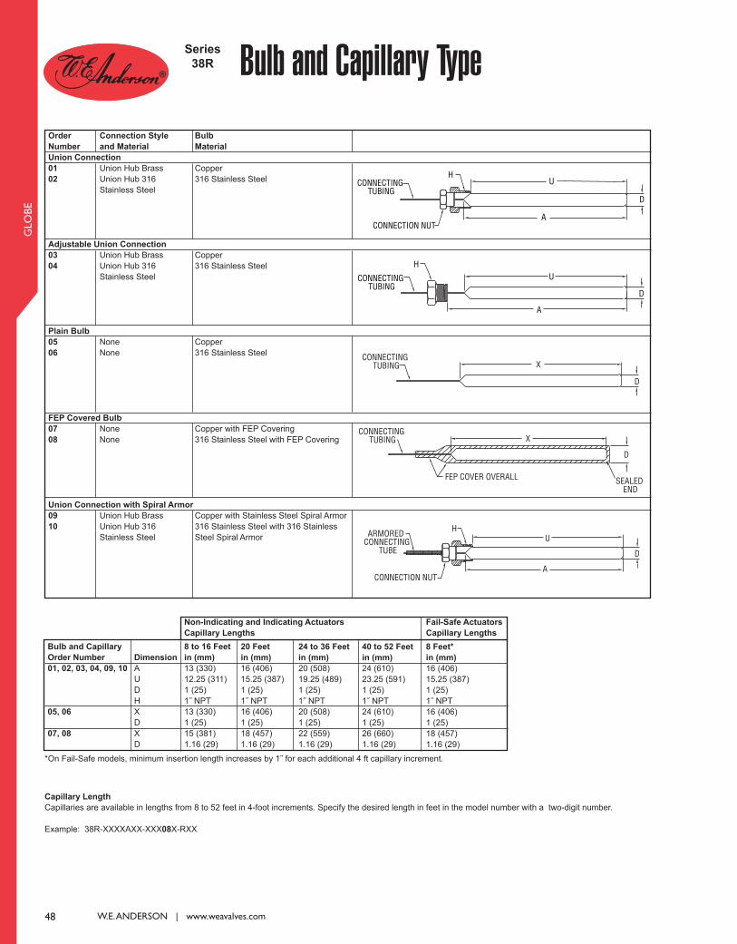
CONNECTING TUBING
H
CONNECTION NUT
D
U
A
48 W.E. ANDERSON | www.weavalves.com
GLO
BE
Series
38R Bulb and Capillary TypeOrder
Number
Union Connection
01
02
Adjustable Union Connection
03
04
Plain Bulb
05
06
FEP Covered Bulb
07
08
Union Connection with Spiral Armor
09
10
Connection Style
and Material
Union Hub Brass
Union Hub 316
Stainless Steel
Union Hub Brass
Union Hub 316
Stainless Steel
None
None
None
None
Union Hub Brass
Union Hub 316
Stainless Steel
Bulb
Material
Copper
316 Stainless Steel
Copper
316 Stainless Steel
Copper
316 Stainless Steel
Copper with FEP Covering
316 Stainless Steel with FEP Covering
Copper with Stainless Steel Spiral Armor
316 Stainless Steel with 316 Stainless
Steel Spiral Armor
Bulb and Capillary
Order Number
01, 02, 03, 04, 09, 10
05, 06
07, 08
Dimension
A
U
D
H
X
D
X
D
8 to 16 Feet
in (mm)
13 (330)
12.25 (311)
1 (25)
1˝ NPT
13 (330)
1 (25)
15 (381)
1.16 (29)
20 Feet
in (mm)
16 (406)
15.25 (387)
1 (25)
1˝ NPT
16 (406)
1 (25)
18 (457)
1.16 (29)
24 to 36 Feet
in (mm)
20 (508)
19.25 (489)
1 (25)
1˝ NPT
20 (508)
1 (25)
22 (559)
1.16 (29)
40 to 52 Feet
in (mm)
24 (610)
23.25 (591)
1 (25)
1˝ NPT
24 (610)
1 (25)
26 (660)
1.16 (29)
8 Feet*
in (mm)
16 (406)
15.25 (387)
1 (25)
1˝ NPT
16 (406)
1 (25)
18 (457)
1.16 (29)
Non-Indicating and Indicating Actuators
Capillary Lengths
Fail-Safe Actuators
Capillary Lengths
*On Fail-Safe models, minimum insertion length increases by 1˝ for each additional 4 ft capillary increment.
Capillary Length
Capillaries are available in lengths from 8 to 52 feet in 4-foot increments. Specify the desired length in feet in the model number with a two-digit number.
Example: 38R-XXXXAXX-XXX08X-RXX
CONNECTING TUBING
H
D
A
U
CONNECTING TUBING X
D
CONNECTING TUBING
FEP COVER OVERALL SEALED END
X
D
CONNECTION NUT
HARMORED CONNECTING
TUBEU
A
D
048_Layout 1 1/29/14 4:15 PM Page 1

49
GLO
BE
Series
38R Thermowells
Series
38R Temperature Ranges
Dimensions
Bulb Length (A)
in (mm)
13 (330)
16 (406)
20 (508)
24 (610)
Length (U)
in (mm)
12.25 (311)
15.25 (387)
19.25 (489)
23.25 (591)
External Connection
(NPT)
1-1/4˝
1-1/4˝
1-1/4˝
1-1/4˝
Thermowells are not recommended for FEP Covered Bulb. Thermowell
length determined by length of ordered bulb.
Order
Number
0
1
2
Description
No Thermowell
316 SS Thermowell
Brass Thermowell
Maximum Pressure
psi (bar)
--
1000 (68.9)
500 (34.5)
ABULB LENGTH
PEXTERNAL CONNECTION
ULENGTH
1.25-18UNEF
WRENCHALLOWANCE
1 [25.4]THREAD
ALLOWANCE
Ø1-7/64[Ø28.18]
Range
Number
R01*
R02*
R03
R04
R05
R06
R07
R09
R10
R11
R12
R13
R14
Nominal Range
°F (°C)
20 to 70 (-7 to 21)
40 to 90 (5 to 32)
30 to 115 (-1 to 46)
50 to 140 (10 to 60)
75 to 165 (24 to 74)
105 to 195 (41 to 91)
125 to 215 (52 to 102)
155 to 250 (68 to 121)
200 to 280 (93 to 138)
225 to 315 (107 to 157)
255 to 370 (124 to 188)
295 to 420 (146 to 216)
310 to 440 (154 to 227)
Single Seat Heating Valves,
Double Seat Heating Valves,
Double Seat Cooling Valves,
All Three-Way Valves °F (°C)
40 to 65 (4 to 18)
65 to 85 (18 to 29)
85 to 110 (29 to 43)
110 to 135 (43 to 57)
135 to 160 (57 to 71)
160 to 190 (71 to 88)
190 to 210 (88 to 99)
210 to 245 (99 to 118)
245 to 275 (118 to 135)
275 to 310 (135 to 152)
305 to 365 (152 to 185)
365 to 415 (185 to 213)
415 to 435 (213 to 224)
Single Seat
Cooling Valves
°F (°C)
N/A
N/A
50 to 80 (10 to 27)
80 to 105 (27 to 41)
105 to 130 (41 to 54)
130 to 155 (54 to 68)
155 to 180 (68 to 82)
180 to 215 (82 to 102)
215 to 245 (102 to 118)
245 to 280 (118 to 138)
275 to 335 (135 to 168)
335 to 385 (168 to 196)
385 to 405 (196 to 207)
Dial Thermometer
Range
°F (°C)
30 to 115 (-1 to 46)
50 to 140 (10 to 60)
30 to 115 (-1 to 46)
50 to 140 (10 to 60)
75 to 165 (24 to 74)
105 to 195 (41 to 91)
125 to 215 (52 to 102)
155 to 250 (68 to 121)
200 to 280 (93 to 138)
225 to 315 (107 to 157)
255 to 370 (124 to 188)
295 to 420 (146 to 216)
310 to 440 (154 to 227)
Recommended Working Span
*Not recommended for single seated valves.
Non-Indicating and Indicating Actuators
Range
Number
R81
R82
R83
R84
R85
R86
R89
R90
R91
R92
R93
R94
R95
R96
Nominal Range and
Recommended Working
Span °F (°C)
40 to 65 (4 to 18)
55 to 80 (13 to 27)
65 to 90 (18 to 32)
80 to 110 (27 to 43)
90 to 115 (32 to 46)
110 to 140 (43 to 60)
140 to 175 (60 to 79)
170 to 195 (77 to 91)
190 to 210 (88 to 99)
205 to 225 (96 to 107)
215 to 250 (102 to 121)
230 to 265 (110 to 129)
245 to 280 (118 to 138)
270 to 300 (132 to 149)
Fail-Safe Actuators
The recommended working span typically falls within the upper third of the nominal range. Single Seat Heating, all Double Seat, and all Three-Way valves have a
recommended working span in this part of the nominal range. However, due to the differing thrust requirements, Single Seat Cooling valves have a recommended
working span in the middle third of the nominal range.
Thermowell To Fit
Standard Bulb Threaded
CONTACT US | U.S. 219/879-8000 | U.K. (+44) (0)1494-461707 | A.U. (+61) (0) 2 4272 2055 | China +852-23181007
049_Layout 1 1/29/14 4:15 PM Page 1

Valve Size
2˝
2-1/2˝
3˝
4˝
5˝
A
In. (mm)
2
(50.80)
2-1/2
(63.50)
3
(76.20)
4
(101.60)
5
(127.00)
B
In. (mm)
2
(50.80)
2
(50.80)
2-1/2
(63.50)
3-1/4
(82.55)
4
(101.60)
C
In. (mm)
3-1/16
(77.79)
3-1/2
(88.90)
4-3/16
(106.36)
5-1/8
(130.18)
6
(152.40)
D
In. (mm)
1-11/16
(42.86)
2
(50.80)
2-7/16
(61.91)
3-1/16
(77.79)
3-5/8
(92.08)
E
In. (mm)
1/2
(12.70)
1/2
(12.70)
5/8
(15.88)
5/8
(15.88)
5/8
(15.88)
F
In. (mm)
1-3/4
(44.45)
2-1/16
(52.39)
2-5/16
(58.74)
2-3/4
(69.85)
3-5/16
(84.14)
G
In. (mm)
2-13/16
(71.44)
3-1/8
(79.38)
3-3/8
(85.73)
4
(101.60)
4-3/8
(111.13)
H
In. (mm)
5-1/8
(130.18)
5-1/8
(130.18)
5-1/8
(130.18)
5-5/8
(142.88)
6
(152.40)
J
In. (mm)
13/16
(20.64)
13/16
(20.64)
1-1/16
(26.99)
1-1/4
(31.75)
1-1/2
(38.10)
K
In. (mm)
5
(127.00)
5
(127.00)
5
(127.00)
5
(127.00)
5
(127.00)
L
In. (mm)
2-1/4
(57.15)
2-3/4
(69.85)
3-3/8
(85.73)
4-3/8
(111.13)
5-3/8
(136.53)
I.D. Width
In. (mm)
1/8
(3.18)
1/8
(3.18)
1/8
(3.18)
1/8
(3.18)
1/8
(3.18)
50 W.E. ANDERSON | www.weavalves.com
BU
TT
ER
FLY
Butterfly ValveLow Cost, S.A.E. Flange, Hydraulic Reservoir Shut Off Valve
Series
SAE
The Series SAE Butterfly Valves are an ideal low cost hydraulic reservoir shut offvalve. These valves are designed to meet the demanding needs of the fluid power in-dustry. Unique features include an O-ring flange face seal complying with S.A.E. J518dimensional requirements. This design provides for bubble tight reservoir shut offup to 25 psi (1.72 bar) and a max temperature of 180°F (82.2°C). The compact enve-lope dimension reduces space requirements. Unit allows for adjustment by incorpo-rating an open/close detent position lock which can be infinitely positioned to achievea desired flow rate. The unique design resists the vibrations associated with hydraulicpumps and pumping systems. Optional fluoroelastomer seals and locking handle areavailable.
APPLICATIONS
As a standard feature on injection molding machines and large earth moving equip-ment, the low cost SAE Valve provides excellent shut-off on the reservoir side of hy-draulic systems. Valve is typically open during normal operation until service wouldbe required on any part of the hydraulic system at which time the valve is closed, al-lowing for service without loss of hydraulic fluid.
H
F
A
JB
L-O-RINGI.D. WIDTH
C
K
D
G
E - 4 PLACES
SPECIFICATIONS
Service: Compatible liquids and gases.
Line Size: 2˝ to 5˝.
Body Style: 2-way, lug butterfly.
End Connections: O-ring flange face seal (SAE J518).
Pressure Limit: Shut-off: 25 psi (1.72 bar) bubble tight; Body shell: 500 psi
(34.5 bar).
Wetted Materials: Body and disc/vane: Cast iron; O-rings: Buna-N or fluoro-
elastomer; Stem: Steel.
Temperature Limits: Buna-N: 180°F (82°C); Fluoroelastomer: 300°F
(149°C).
Model
SAE-20
SAE-25
SAE-30
SAE-40
SAE-50
Fluoroelastomer O-ring seals. Add VIT suffix (SAE-30-VIT)
Locking handle. Add LHR suffix (SAE-30-LHR)
S.A.E. Flange Size
2˝
2-1/2˝
3˝
4˝
5˝
050_Layout 1 1/29/14 4:15 PM Page 1

51
BU
TT
ER
FLY
Series
BFV Butterfly ValveLow Cost, Lever Operated, Lug or Wafer Pattern, 225 psig
The most critical aspect of the Series BFV Butterfly Valves is the cartridge seatdesign, which alleviates installation problems associated with common “dove tail de-sign” seats. Valve torque is lower and more consistent because the seat dynamics donot rely on being mated between two flanges. Precision machining of the disc andbody allow the cartridge design to maintain a tighter disc to seat tolerance, providinga perfect low torque seal each and every time the valve is cycled. Seat to disc seal isindependent of flange support and capable of full rated dead end service. Select fromwafer or lug patterns with either a 10-position locking handle lever or manual gearoperator. Standard valves provide bubble tight sealing to 225 psi (15.5 bar) and aredesigned to comply with MSS-SP-67 and API-609.
FEATURES
• Phenolic backed cartridge seat design for extended service and ease of
replacement. Can be used for vacuum service.
• Extended neck for insulation – no fabricated extensions required.
• Machined flats attach disc/stem – no pins.
• Valve features a retainer lip for dead end service.
• Triple seal reduces possibility of external leakage.
• Silicone free from the factory – no aftermarket cleaning required.
APPLICATIONS
• Perfect for on-off or throttling service
• Ideal for shut-off of water in chillers, cooling towers, and thermal storage
systems
• Sewage systems, waste water treatment
SPECIFICATIONS
VALVE BODY
Service: Compatible liquids, gases, and steam.
Line Size: 2˝ to 12˝.
Body Style: 2-way, wafer or lug butterfly.
End Connections: Flange, to be used with flanges that are ANSI Class 125
(B16.1) and ANSI Class 150 (B16.5) dimensions.
Pressure Limit: 225 psi (15.5 bar) WOG.
Wetted Materials:
Body material: Ductile iron;
Disc: 316 SS;
Seat and O-ring: EPDM or PTFE;
Stem: 410 SS.
Temperature Limits: Disc: EPDM: -50 to 250°F (-46 to 121°C); PTFE: 0 to
300°F (-18 to 149°C).
Bearings: Nylatron.
Flow Rate: See Cv chart.
Operator: 2 to 6˝: 10-position locking hand lever; 8 to 12˝: manual gear.
B
A
n =# OF HOLES
EPDM Seats
Service Pressure
50 psi
100 psi
150 psi
200 psi
PTFE Seats
Service Pressure
50 psi
100 psi
150 psi
200 psi
Operating Torque Valves (inch lb)
Size (inches)
Size (inches)
2
86
108
126
150
2-1/2
126
144
150
198
3
179
195
210
297
4
295
310
335
400
5
540
610
699
725
6
750
780
847
940
8
1440
1490
1549
1800
10
2466
2910
3360
3890
12
3510
4100
5560
7558
2
125
130
142
180
2-1/2
130
145
160
220
3
195
210
248
340
4
390
430
443
490
5
650
690
720
795
6
890
940
974
1020
8
1690
1710
1770
1890
10
3699
4365
5040
5835
12
5265
6150
8340
11367
Degree Opening
Size
2˝
2-1/2˝
3˝
4˝
5˝
6˝
8˝
10˝
12˝
Full Open
10°
0.1
0.2
0.3
0.5
0.8
2
3
4
5
20°
5
8
12
17
29
45
89
151
234
30°
12
20
22
36
61
95
188
320
495
40°
24
37
39
78
133
205
408
694
1072
50°
45
65
70
139
237
366
727
1237
1911
60°
64
98
116
230
392
605
1202
2047
3162
70°
90
144
183
364
620
958
1903
3240
5005
90°
135
220
302
600
1022
1579
3136
5340
8250
80°
125
204
275
546
930
1437
2854
4859
7505
Cv is the number of U.S. GPM of 60°F water that will pass through
the valve with a 1 PSI pressure drop.
Cv Values
Dimensions (in)
C
A
Bn =# OF HOLES
Size
6˝
8˝
10˝
12˝
A
8.9
10.24
11.5
13.27
B
5.47
6.89
7.99
9.53
C
2-1/4
2-1/2
2-3/4
3-1/8
n, WF
8
8
12
12
n, LT
8
8
12
12
Cv
1579
3136
5340
8250
Weight
17.2
29.1
42.33
71.65
Size
2˝
2-1/2˝
3˝
4˝
5˝
A
6.34
6.89
7.13
7.87
8.39
B
3.15
3.5
3.74
4.49
5
C
1-3/4
1-7/8
1-7/8
2-1/8
2-1/4
n, WF
4
4
4
4
8
Cv
135
220
302
600
1022
Weight
5.5
7.05
7.93
10.8
15.43
n, LT
4
4
4
8
8
Wafer Style
Lug Style
Wafer Style
“WF”
Lug Style
“LT”
CONTACT US | U.S. 219/879-8000 | U.K. (+44) (0)1494-461707 | A.U. (+61) (0) 2 4272 2055 | China +852-23181007
BFV202WFB311HL0 WF=Wafer Pattern LT=Lug Pattern
Liner
EPDM
PTFE
EPDM
PTFE
EPDM
PTFE
EPDM
PTFE
EPDM
PTFE
EPDM
PTFE
EPDM
PTFE
EPDM
PTFE
EPDM
PTFE
EPDM
PTFE
Liner
EPDM
PTFE
EPDM
PTFE
EPDM
PTFE
EPDM
PTFE
EPDM
PTFE
EPDM
PTFE
EPDM
PTFE
EPDM
PTFE
Size
6˝
8˝
10˝
12˝
Size
2˝
2-1/2˝
3˝
4˝
5˝
Model
BFV202WFB311HL0
BFV202WFB341HL0
BFV202LTB311HL0
BFV202LTB341HL0
BFV225WFB311HL0
BFV225WFB341HL0
BFV225LTB311HL0
BFV225LTB341HL0
BFV203WFB311HL0
BFV203WFB341HL0
BFV203LTB311HL0
BFV203LTB341HL0
BFV204WFB311HL0
BFV204WFB341HL0
BFV204LTB311HL0
BFV204LTB341HL0
BFV205WFB311HL0
BFV205WFB341HL0
BFV205LTB311HL0
BFV205LTB341HL0
Model
BFV206WFB311HL0
BFV206WFB341HL0
BFV206LTB311HL0
BFV206LTB341HL0
BFV208WFB312MG0
BFV208WFB342MG0
BFV208LTB312MG0
BFV208LTB342MG0
BFV210WFB312MG0
BFV210WFB342MG0
BFV210LTB312MG0
BFV210LTB342MG0
BFV212WFB312MG0
BFV212WFB342MG0
BFV212LTB312MG0
BFV212LTB342MG0
051_Layout 1 1/29/14 4:16 PM Page 1

AC
TU
ATO
RS
52 W.E. ANDERSON | www.weavalves.com
The W.E. Anderson Series ACT Ac-
tuators are available in either pneu-matic or electric models. The wide rangeof torques and voltages means there isan actuator for almost any application.The standard ISO 5211 mounting config-uration makes installation to any valveor damper quick and simple. W.E. Anderson pneumatic ACT modelsare a compact rack-and-pinion designwith a symmetrical structure that en-sures fast and steady action, high preci-sion and high output power. Thecorrosion resistant anodized aluminumbody is designed to withstand the harshand abusive industrial environments andprovide reliable service. We offer doubleacting and spring return models in a va-riety of sizes to fit any application. W.E. Anderson electric ACT models areavailable in two-position or modulatingconfigurations and NEMA 4X or NEMA7 rated enclosures. All electric actuatorsutilize a high grade powder coated alu-minum enclosure with visual indicators.
The two-position models come standardwith two auxiliary switches, and modu-lating models offer an output for positionmonitoring. Certain models areequipped with manual overrides allow-ing the operator to cycle the valve man-ually for installation or maintenancechecks.
FEATURES
• ISO 5211 Mounting configuration or
easy installation
• Pneumatic actuators offer corrosion
resistance anodized finish
• NAMUR mounting configuration on
pneumatic actuators
• Two-position electric actuators
include auxiliary limit switches
• Modulating electric actuators offer
an output for position monitoring
SPECIFICATIONS
Pneumatic “DA” and “SR” Series
Type: DA series is double-acting
and SR series is spring return (rack
and pinion).
Normal Supply Pressure:
DA: 40 to 115 psi (2.7 to 7.9 bar);
SR: 80 psi (5.5 bar).
Maximum Supply Pressure: 120
psi (8.6 bar).
Air Connections:
DA01: 1/8˝ female NPT;
DA02 to DA5: 1/4˝ female NPT;
SR02 to SR07: 1/4˝ female NPT.
Housing Material: Anodized alu-
minum body and epoxy coated alu-
minum end caps.
Temperature Limits: -40 to 176°F
(-40 to 80°C).
Accessory Mounting: NAMUR
standard.
Electric “TD” and “MD” Series
Power Requirements: 110 VAC,
220 VAC, 24 VAC or 24 VDC (MD
models not available in 24 VDC).
Power Consumption: See manual.
Cycle Time (per 90°):
TD01 4 s;
MD01: 10 s;
TD02 and MD02: 20 s;
TD03 and MD03: 30 s.
Duty Rating: 85%.
Enclosure Rating: NEMA 4X
(IP67).
Housing Material: Powder coated
aluminum.
Temperature Limits: -22 to 140°F
(-30 to 60°C).
Electrical Connection: 1/2˝ female
NPT.
Modulating Input: 4 to 20 mA.
Standard Features: Manual over-
ride, position indicator, and TD mod-
els come with two limit switches.
Electric “TI” and “MI” Series
Power Requirements: 110 VAC,
220 VAC, 24 VAC or 24 VDC.
Power Consumption: See manual.
Cycle Time (per 90°):
TI01 and MI01: 2.5 s;
TI02 and MI02: 5 s;
TI03 and MI03: 5 s;
TI04 and MI04: 10 s;
TI05 and MI06: 15 s.
Duty Rating:
Two-Position: TI01-TI06: 25%.
Modulating: MI01-MI06: 75%.
Enclosure Rating: NEMA 7.
Housing Material: Powder coated
aluminum.
Temperature Limits: -40 to 140°F
(-40 to 60°C).
Electrical Connection: 1/2˝ female
NPT.
Modulating Input: 4 to 20 mA.
Standard Features: Position indica-
tor and two limit switches.
Pneumatic and Electric ActuatorsActuators for Valve and Damper Automation
Series
ACT
ACT-TD01-110VAC
ACT-MI02-110VAC
ACT-SR03
A
052_Layout 1 1/29/14 4:16 PM Page 1

AC
TU
ATO
RS
53
Pneumatic
Models
ACT-DA01
ACT-DA02
ACT-DA03
ACT-DA04
ACT-DA05
ACT-DA06
ACT-DA07
ACT-DA08
ACT-DA09
ACT-SR02
ACT-SR03
ACT-SR04
ACT-SR05
ACT-SR06
ACT-SR07
ACT-SR08
ACT-SR09
ACT-SR10
ACT-SR11
Popular Pneumatic Models
Model
ACT-DA01
ACT-DA02
ACT-DA03
ACT-DA04
ACT-DA05
ACT-DA06
ACT-DA07
ACT-DA08
ACT-DA09
40 psi
49
104
182
302
396
567
845
1497
2253
50 psi
61
130
228
377
495
709
1056
1871
2816
60 psi
74
155
274
453
594
851
1267
2245
3379
70 psi
86
181
319
528
693
993
1478
2619
3942
80 psi
98
207
365
603
792
1135
1690
2993
4506
90 psi
110
233
411
679
891
1277
1901
3367
5069
100 psi
123
259
456
754
990
1419
2112
3742
5632
110 psi
135
285
502
830
1089
1561
2323
4116
6195
115 psi
142
300
529
875
1148
1649
2450
4340
6533
Air Pressure
DA Double-Action Output Torque (lb-in)
Double Acting Actuator Torque
Electric Models
ACT-TD01-110VAC
ACT-TD02-110VAC
ACT-TD03-110VAC
ACT-TD04-110VAC
ACT-TD05-110VAC
ACT-MD01-110VAC
ACT-MD02-110VAC
ACT-MD03-110VAC
ACT-MD04-110VAC
ACT-MD05-110VAC
ACT-TI01-110VAC
ACT-TI02-110VAC
ACT-TI03-110VAC
ACT-TI04-110VAC
ACT-TI05-110VAC
ACT-TI06-110VAC
ACT-TI07-110VAC
ACT-TI08-110VAC
ACT-TI09-110VAC
ACT-TI10-110VAC
ACT-MI01-110VAC
ACT-MI02-110VAC
ACT-MI03-110VAC
ACT-MI04-110VAC
ACT-MI05-110VAC
ACT-MI06-110VAC
ACT-MI07-110VAC
ACT-MI08-110VAC
ACT-MI09-110VAC
ACT-MI10-110VAC
Model
ACT-SR02
ACT-SR03
ACT-SR04
ACT-SR05
ACT-SR06
ACT-SR07
ACT-SR08
ACT-SR09
ACT-SR10
Spring
Quantity
10
10
10
10
10
10
10
10
10
Air Pressure
SR Single Acting Pneumatic Actuator (lb-in)
0°
Start
111
199
348
430
608
783
1682
2303
3479
90°
End
86
143
254
312
458
663
1208
1483
2274
0°
Start
137
245
424
529
750
994
2056
2866
4337
90°
End
112
189
330
411
599
874
1583
2046
3133
0°
Start
163
291
499
628
891
1206
2430
3429
5195
90°
End
138
235
405
510
741
1085
1957
2609
3991
0°
Start
189
336
575
727
1033
1417
2804
3992
6053
90°
End
164
280
481
609
883
1297
2331
3173
4849
0°
Start
215
382
650
826
1175
1628
3178
4556
6911
90°
End
189
326
556
708
1025
1508
2705
3736
5707
0°
Start
231
409
695
885
1260
1755
3403
4894
7426
90°
End
205
353
601
767
1110
1635
2930
4074
6222
90°
Start
96
176
274
381
536
817
1416
2363
3549
0°
End
70
120
180
263
386
696
938
1575
2407
70 psi 80 psi 90 psi 100 psi 110 psi 115 psi Spring Torque
Spring Return Actuator Torque
Popular Electric Models
CONTACT US | U.S. 219/879-8000 | U.K. (+44) (0)1494-461707 | A.U. (+61) (0) 2 4272 2055 | China +852-23181007
Description
Double Acting Pneumatic Actuator, 98 in-lb
Double Acting Pneumatic Actuator, 207 in-lb
Double Acting Pneumatic Actuator, 365 in-lb
Double Acting Pneumatic Actuator, 603 in-lb
Double Acting Pneumatic Actuator, 792 in-lb
Double Acting Pneumatic Actuator, 1135 in-lb
Double Acting Pneumatic Actuator, 1690 in-lb
Double Acting Pneumatic Actuator, 2993 in-lb
Double Acting Pneumatic Actuator, 4506 in-lb
Spring Return Pneumatic Actuator, 95 in-lb
Spring Return Pneumatic Actuator, 176 in-lb
Spring Return Pneumatic Actuator, 274 in-lb
Spring Return Pneumatic Actuator, 381 in-lb
Spring Return Pneumatic Actuator, 536 in-lb
Spring Return Pneumatic Actuator, 815 in-lb
Spring Return Pneumatic Actuator, 1411 in-lb
Spring Return Pneumatic Actuator, 2460 in-lb
Spring Return Pneumatic Actuator, 3733 in-lb
Spring Return Pneumatic Actuator, 6166 in-lb
ACCESSORIES
R2-2120, Air Regulator
AFR2-2, Instrument Air Filter Regulator
VB-01, Volume Booster
SN-5A, 5/2 NAMUR 110 VAC Solenoid
SN-3A, 3/2 NAMUR 110 VAC Solenoid
Description
Electric Two-Position, 177 in-lb, 110 VAC
Electric Two-Position, 442 in-lb, 110 VAC
Electric Two-Position, 885 in-lb, 110 VAC
Electric Two-Position, 1770 in-lb, 110 VAC
Electric Two-Position, 3540 in-lb, 110 VAC
Electric Modulating, 265 in-lb, 110 VAC
Electric Modulating, 442 in-lb, 110 VAC
Electric Modulating, 885 in-lb, 110 VAC
Electric Modulating, 1770 in-lb, 110 VAC
Electric Modulating, 3540 in-lb, 110 VAC
EXP Electric Two-Position, 100 in-lb, 110 VAC
EXP Electric Two-Position, 200 in-lb, 110 VAC
EXP Electric Two-Position, 300 in-lb, 110 VAC
EXP Electric Two-Position, 400 in-lb, 110 VAC
EXP Electric Two-Position, 675 in-lb, 110 VAC
EXP Electric Two-Position, 1000 in-lb, 110 VAC
EXP Electric Two-Position, 1500 in-lb, 110 VAC
EXP Electric Two-Position, 2000 in-lb, 110 VAC
EXP Electric Two-Position, 3840 in-lb, 110 VAC
EXP Electric Two-Position, 5000 in-lb, 110 VAC
EXP Electric Modulating, 100 in-lb, 110 VAC
EXP Electric Modulating, 200 in-lb, 110 VAC
EXP Electric Modulating, 300 in-lb, 110 VAC
EXP Electric Modulating, 400 in-lb, 110 VAC
EXP Electric Modulating, 675 in-lb, 110 VAC
EXP Electric Modulating, 1000 in-lb, 110 VAC
EXP Electric Modulating, 1500 in-lb, 110 VAC
EXP Electric Modulating, 2000 in-lb, 110 VAC
EXP Electric Modulating, 3840 in-lb, 110 VAC
EXP Electric Modulating, 5000 in-lb, 110 VAC
053_Layout 1 1/29/14 4:17 PM Page 1

54 W.E. ANDERSON | www.weavalves.com
SO
LEN
OID
S
W
The Series SN Solenoid Valves are designed to easily mount directly to pneu-matic valve actuators reducing the need for tubing, fittings or brackets, reducing as-sembly cost. The SN solenoid comes with nitrile o-rings and offers a manual overrideas a standard feature. The 3/2 solenoids are designed for spring return actuators and5/2 solenoids are designed to be used with double acting actuators. The SN series isavailable in a variety of voltage for any application.
FEATURES
• NAMUR mount means the solenoid can be mounted directly to valve
actuators.
• Designed for double acting or spring return actuators.
• 100% continuous duty rating.
• Manual override.
SPECIFICATIONS
Service: Air only.
Power Requirements: 24 VAC, 110 VAC, 220 VAC, 12 VDC, or 24 VDC.
Supply Pressure: 22 to 116 psi (1.5 to 7.9 bar).
Air Connections: 1/4˝ FNPT.
Temperature Limits: 23 to 140°F (-5 to 60°C).
Electrical Connection: DIN 43650 form A.
Enclosure Rating: IP65.
Mounting: NAMUR.
Standard Features: Manual override.
Weight: 1.0 lb (.45 kg).
Agency Approvals: CE.
NAMUR Mount Solenoid ValveManual Override, 100% Duty Rating
Model
SN-5A
SN-5B
SN-5C
SN-5E
SN-5D
SN-3A
SN-3B
SN-3C
SN-3E
SN-3D
Power
110 VAC
220 VAC
24 VAC
24 VDC
12 VDC
110 VAC
220 VAC
24 VAC
24 VDC
12 VDC
Series
SN
MANUALOVERRIDE
2-49/64[70.25]
1-37/64[40.08]
1-1/16[26.99]
2X1/4 NPTF
7/8[22.23]
5-11/64[131.37]
1-25/64[35.32]
2-5/8[66.68]
3X 1/4 NPTF1-47/64[44.05]
5-21/64[135.33]
1-1/16[26.99]
63/64[25.00]
61/64[24.21]
NAMURSTANDARD
MANUALOVERRIDE
1-37/64[40.08]
Action
5/2
5/2
5/2
5/2
5/2
3/2
3/2
3/2
3/2
3/2
SN-3X Models
SN-5X Models
Model SW mounted to an actuator
Actuator Type
Double Acting
Double Acting
Double Acting
Double Acting
Double Acting
Spring Return
Spring Return
Spring Return
Spring Return
Spring Return
054_Layout 1 1/29/14 4:17 PM Page 1

55
REFERENCE TABLES
HAZARDOUS LOCATIONS LISTINGS
Type 1
Type 2
Type 3
Type 3R
Type 3S
Type 4
Type 4X
Type 5
Type 6
Type 6P
Type 7
Type 8
Type 9
Type 10
Type 11
Type 12
Type 12K
Type 13
Flammable gases or vapors are or may be present in sufficient quantities to produce explosive or ignitable mixtures.
Gases or vapors are or may be in the atmosphere in normal operations.
Containing acetylene.
Containing hydrogen, ethylene oxide & propylene oxide or gases or vapors of equivalent hazard.
Containing ethyl-ether vapor, ethylene or cyclopropane.
Containing gasoline, hexane, naptha, benzine, butane, propane, alcohol, acetone, lacquer solvent or natural gas.
Gases or vapors are not normally present. They may be present due to leakage, accidents or maintenance. It is possible for one atmosphere
to contain the same items as listed for Groups of Division I of this class.
Combustible dust may be present in sufficient quantities to produce an explosive atmosphere.
Dust in suspension. Dust is or may be present in the atmosphere due to normal operating conditions.
Containing metal dust, including aluminum, magnesiums and their commercial alloys, and other metals of similar hazardous characteristics.
Containing carbon black, coal or coke dust.
Containing flour, starch or grain dust.
Dust not normally in suspension. Possibly containing the same items as listed for Groups of Division I of this class.
Ignitable fibers are present, but not necessarily present in air in quantities sufficient to produce ignitable mixtures.
Easily ignitable fibers or materials producing combustible flyings are handled, manufactured or used.
Easily ignitable fibers are stored or handled.
General purpose - indoor.
Drip-proof - indoor. Protects against limited amounts of falling liquids and dirt.
Dust-tight, raintight and sleet resistant - outdoor. Protects against windblown dust, rain sleet and external ice formation.
Same as Type 3, except not dust-tight.
Same as Type 3, but provides for operation of external mechanism when ice-laden.
Watertight and dust-tight - indoor and outdoor. Protects against windblown dust and rain, splashing water and hose-directed water.
Same as Type 4 except also corrosion resistant.
Dust-tight - indoor. Protects against dust and falling dirt.
Submersible, watertight and dust-tight - indoor and outdoor. Protects against water entry during occasional temporary submersion to a lim-
ited depth.
Same as Type 6 except for prolonged submersion.
Class I indoor hazardous locations. Explosion-proof, may be A, B, C or D.
Class I indoor or outdoor hazardous locations - oil immersed equipment, may be A, B, C or D.
Class II indoor hazardous locations. Explosion-proof, may be E, F or G.
Mining Enforcement Safety Administration. Explosion-proof in methane or natural gas.
Corrosion resistant and drip-proof - oil-immersed - indoor.
Dust-tight and drip-tight - indoor, non-corrosive dripping liquids.
Same as Type 12 except enclosures have knockouts.
Oil-tight and dust-tight - indoors, non-corrosive spray of water, oil and coolant.
Class I (-4)
Division I (-4A)
Group A (-2)
Group B (-2)
Group C (-2)
Group D (-2)
Division II (-4B)
Class II (-5)
Division I (-5A)
Group E (-2)
Group F (-2)
Group G (-2)
Division II (-5D)
Class III (-6)
Division I (-6A)
Division II (-6B)
NEMA STANDARDS FOR INDUSTRIAL ENCLOSURES
CONTACT US | U.S. 219/879-8000 | U.K. (+44) (0)1494-461707 | A.U. (+61) (0) 2 4272 2055 | China +852-23181007
055_Layout 1 1/29/14 4:17 PM Page 1

56 W.E. ANDERSON | www.weavalves.com
REFERENCE TABLES
Diam.
in
Inches
1
1-1/2
2
2-1/2
3
3-1/2
4
4-1/2
5
5-1/2
6
6-1/2
7
7-1/2
8
8-1/2
9
9-1/2
10
11
12
13
14
15
16
17
18
19
20
21
22
23
24
25
26
27
28
29
Area
Square
Feet
.0054
.0123
.0218
.0341
.0491
.0668
.0873
.1105
.1364
.1650
.1964
.2305
.2673
.3068
.3491
.3940
.4418
.4923
.5454
.6600
.7854
.9218
1.069
1.227
1.396
1.576
1.767
1.969
2.182
2.405
2.640
2.885
3.142
3.409
3.687
3.976
4.276
4.587
Diam.
in
Inches
30
31
32
33
34
35
36
37
38
39
40
41
42
43
44
45
46
47
48
49
50
51
52
53
54
56
58
60
62
64
66
68
70
72
74
76
78
80
Area
Square
Feet
4.909
5.241
5.585
5.940
6.305
6.611
7.069
7.467
7.876
8.296
8.727
9.168
9.621
10.08
10.56
11.04
11.54
12.05
12.57
13.10
13.64
14.19
14.75
15.32
15.90
17.10
18.35
19.63
20.97
22.34
23.76
25.22
26.73
28.27
29.87
31.50
33.18
34.91
Mercury at 0°C (32°F)
Altitude
in feet
-1,000
0
1,000
2,000
3,000
4,000
5,000
6,000
7,000
8,000
9,000
10,000
15,000
20,000
25,000
30,000
35,000
40,000
45,000
50,000
Inches
of Mercury
31.02
29.921
28.86
27.82
26.81
25.84
24.89
23.98
23.09
22.22
21.38
20.58
16.88
13.75
11.10
8.88
7.04
5.54
4.36
3.436
In
Millimeters
of Mercury
787.9
760.0
732.9
706.6
681.1
656.3
632.3
609.0
586.4
564.4
543.2
522.6
428.8
349.1
281.9
225.6
178.7
140.7
110.8
87.30
(Based on 68°F and 14.7 lb. abs.)
Acetylene
Air
Ammonia
Argon
Butane-N
Butane-ISO
Carbon Dioxide
Carbon Monoxide
Chlorine
Ethane
Helium
Hydrogen
Methane
Natural Gas
Nitric Oxide
Nitrogen
Nitrous Oxide
Oxygen
Propane
Sulphur Dioxide
C2H2
. . . . . . .
NH3
A
C4H40
(CH)3)2CH CH3
CO2
CO
CL2
C2H6
He
H2
CH4
. . . . . .
NO
N2
N20
02C3H8
SO2
.897
1.000
.587
1.378
2.390
1.990
1.517
.966
2.452
1.035
.138
.070
.553
.665
(Approx. Avg.)
1.035
.966
1.518
1.103
1.550
2.209
1 Cu. Ft./Hr. 1 Cu. Ft./Min.
.0166 Cu. Ft./Min.
.4719 LPM
28.316 LPH
471.947 CC/Min.
28317 CC/Hr.
.1247 Gal/Min.
7.481 Gal/Hr.
60 Cu. Ft./Hr.
28.316 LPM
1699 LPH
28317 CC/Min.
1,699,011 CC/Hr.
7.481 Gal/Min.
448.831 Gal/Hr.
1 CC/Min.
60 CC/Hr.
.000035 Cu. Ft./Min.
.0021 Cu. Ft./Hr.
.001 LPM
.06 LPH
.00026 Gal/Min.
.0159 Gal/Hr.
1 CC/Hr.
.0167 CC/Min.
.0000005 Cu. Ft./Min.
.00003 Cu. Ft./Hr.
.000017 LPM
.001 LPH
.000004 Gal/Min.
.00026 Gal/Hr.
1 LPH
.0166 LPM
.00059 Cu. Ft./Min.
.035 Cu. Ft./Hr.
16.667 CC/Min.
1000 CC/Hr.
.004 Gal/Min.
.264 Gal/Hr.
1 LPM
60 LPH
.035 Cu. Ft./Min.
2.1189 Cu. Ft./Hr.
1000 CC/Min.
60,002 CC/Hr.
.264 Gal/Min.
15.851 Gal/Hr.
1 Gal/Min.
60 Gal/Hr.
.1337 Cu. Ft./Min.
8.021 Cu. Ft./Hr.
3.785 LPM
227.118 LPH
3,785.412 CC/Min.
227,125 CC/Hr.
1 Gal/Hr.
.0167 Gal/Min.
.002 Cu. Ft./Min.
.1337 Cu. Ft./Hr.
.063 LPM
3.785 LPH
63.069 CC/Min.
3785 CC/Hr.
AREA OF CIRCLES IN FT2 ALTITUDE PRESSURE TABLE SPECIFIC GRAVITIES OF GASES
VOLUME EQUIVALENTS
FLOW EQUIVALENTS
1 Cu. Ft.
1 Gal. (U.S.)
1 Liter
1728 Cu. In.
7.481 Gal. (U.S.)
28.317 Liters
28.317 Cu. Cm.
231 Cu. In.
.1337 Cu. Ft.
3.785 Liters
3785 Cu. Cm.
.0353 Cu. Ft.
.2642 Gal. (U.S.)
1000 Cu. Cm.
056_Layout 1 1/29/14 4:18 PM Page 1

Dwyer Instruments, Inc. produces a broad line of competitively priced valves and valve control products under its Proximity
Controls and W. E. Anderson Division. This catalog provides details of W.E. Anderson’s full valve product line, which includes
globe, butterfly, ball, manifold and solenoid valves. Within each valve type W.E. Anderson offers many different options so that
you can select the proper valve to meet your specific application needs. Proximity Controls also offer valve position indicators,
valve positioners and electric and pneumatic actuators to complete your valve automation package.
Dwyer entered into the valve business in 1989 with the acquisition of Proximity Controls. Proximity Controls manufactures a full
line of position indicating products for valves including the magnetic drive featured in the Mark Series. Dwyer then expanded by
purchasing the rugged Hi-FlowTM control valve line from Taylor in 1991. Besides acquisitions Dwyer has continued to expand
the product line to offer our customers a complete source for all of their valve needs.
In addition to making and selling quality valve products, Dwyer is committed to a standard of customer service – including
competitive prices and knowledgeable, courteous technical support – that generates and sustains long-term relationships.
DWyER INSTRumENTS, INC. - DISCouNT SChEDuLE
RIGHT CHOICE. RIGHT PRICE. RIGHT NOW. STANDARD TERMS & CONDITIONS OF SALE
Dwyer Instruments, Inc. - Standard Terms and Conditions of Sale
1. Prices and Specifications are subject to change without notice.
2. Shipping dates are approximate. They are dependent upon credit approval and subject to delays beyond our control.
3. Terms: Net 30 days to companies with established credit rating. In the event Buyer fails to fulfill previous terms of payment, or in case
Seller shall have any doubt at any time as to Buyer's financial responsibility, Seller may decline to make further deliveries except upon
receipt of cash in advance or other special arrangements.
4. Point and Title: All material is sold EXW Ex Works Dwyer Instruments, Inc. Title to all material sold shall pass to buyer upon delivery
by Seller to carrier at shipping point.
5. State and Local Taxes: Any taxes which the Seller may be required to pay or collect upon or with respect to the sale, purchase,
delivery, use or consumption of any of the material covered hereby shall be for the account of the Buyer and shall be added to the
purchase price.
6. Special tooling, dies, silk screens and molds acquired specially to produce goods for Buyer remain the property of Dwyer Instruments,
Inc., and may not be removed. They will be maintained in good condition for a minimum period of three years from the date of the
original purchase order.
7. Trade Compliance: Buyer acknowledges that the products, software, and technology, including technical information and documents
(collectively “Items”), of Dwyer Instruments, Inc., are subject to regulation by agencies of the U.S. government including, but not limited
to, the U.S. Department of Commerce. Buyer shall comply with the Export Administration Regulations (EAR) and all applicable
U.S.laws and regulations regarding the sale, delivery and transfer of said Items. Buyer shall not, without first obtaining the required
licenses, authorizations or approvals from the appropriate U.S. government agency; (i) export, re-export, transfer or divert any Item
directly or indirectly to any country or national resident thereof, or any person, entity or country that has restrictions imposed upon
them by the U.S. government, (ii) engage in, or knowingly sell to any party engaged in activity related to the development, production,
use, testing, or maintenance of Weapons of Mass Destruction, including uses related to nuclear, missile, chemical or biological
warfare, or (iii) engage in, or knowingly sell to any party engaged in activity related to the development, production, use, or
maintenance of any safeguarded or unsafeguarded nuclear fuel facility or components for such facilities. Buyer shall fully cooperate
with Seller, without charge, in any official audit or inspection by an authorized agent, official, employee, or accredited representative
of the U.S. government. Buyer shall indemnify and hold Seller harmless from, or in connection with, any violation of this Section by
Buyer, its employees, consultants, agents, or customers. The obligations, requirements and claims described herein shall survive the
expiration of any business relationship with Dwyer Instruments, Inc., including its divisions, subsidiaries and affiliated companies.
8. Limited Warranty: The Seller warrants all Dwyer Instruments and equipment to be free from defects in workmanship or material under
normal use and service for a period of one year from date of shipment. Liability under this warranty is limited to repair or replacement
EXW Ex Works Dwyer Instruments, Inc. of any parts which prove to be defective within that time or repayment of the purchase price
at the Seller's option provided the instruments have been returned, transportation prepaid, within one year from date of purchase. All
technical advice, recommendations and services are based on technical data and information which the Seller believes to be reliable
and are intended for use by persons having skill and knowledge of the business, at their own discretion. In no case is Seller liable
beyond replacement of equipment EXW Ex Works Dwyer Instruments, Inc. or the full purchase price. This warranty does not apply if
the maximum ratings label is removed or if the instrument or equipment is abused, altered, used at ratings above the maximum
specified, or otherwise misused in any way.
THIS EXPRESS LIMITED WARRANTY IS IN LIEU OF AND EXCLUDES ALL OTHER REPRESENTATIONS MADE BY
ADVERTISEMENTS OR BY AGENTS AND ALL OTHER WARRANTIES, BOTH EXPRESS AND IMPLIED. THERE ARE NO IMPLIED
WARRANTIES OF MERCHANTABILITY OR OF FITNESS FOR A PARTICULAR PURPOSE FOR GOODS COVERED HEREUNDER.
9. Buyer's Remedies: THE BUYER'S EXCLUSIVE AND SOLE REMEDY ON ACCOUNT OF OR IN RESPECT TO THE FURNISHING
OF NON-CONFORMING OR DEFECTIVE MATERIAL SHALL BE TO SECURE REPLACEMENT THEREOF AS AFORESAID. THE
SELLER SHALL NOT IN ANY EVENT BE LIABLE FOR THE COST OF ANY LABOR EXPENDED ON ANY SUCH MATERIAL OR FOR
ANY SPECIAL, DIRECT, INDIRECT, CONSEQUENTIAL OR INCIDENTAL DAMAGES TO ANYONE BY REASON OF THE FACT
THAT IT SHALL HAVE BEEN NON-CONFORMING OR DEFECTIVE.
10. Acceptance: All orders shall be subject to the terms and conditions contained or referred to in the Seller's quotation, acknowledgment,
and to those listed here and to no others whatsoever. No waiver, alteration or modification of these terms and conditions shall be
binding unless in writing and signed by an executive officer of the Seller. All orders are subject to written acceptance by Dwyer
Instruments, Inc., Michigan City, Indiana, U.S.A.
Note:
Each item (model, range, part number, etc.) is discounted
independently. In an order for more than one item, different items
cannot be combined to earn a greater discount.
Most items are subject to STANDARD schedule at right. Prices
followed by the symbol b are subject to discounts per schedule B.
Certain items such as repairs, repair parts, EXPL and WP housings,
prices followed by the symbol n, special scale and tag charges are
priced at net and earn no discount.
Industrial Discount Schedule*
Quantity of
Each Item
1-24
25-99
100-249
250-499
500-Up
Discounts
Standard
Net
5%
10%
15%
20%
Schedule B
Net
Net
5%
10%
15%
*Please contact us for discount schedules for other account types.
ifcibc_Layout 1 3/20/14 11:56 AM Page 1

CT-VC
©Copyright 2014 Dwyer Instruments, Inc. 2/14
Printed in U.S.A.
DWYER INSTRUMENTS, INC.
P.O. Box 373
Michigan City, IN 46360
Return Service Requested
ofcobc_Layout 1 1/29/14 4:21 PM Page 1