Embed Size (px)
Citation preview
CSCI 8150Advanced Computer Architecture
Hwang, Chapter 7Multiprocessors and Multicomputers7.1 Multiprocessor System Interconnects
Generalized Multiprocessor System
Generalized Multiprocessor System
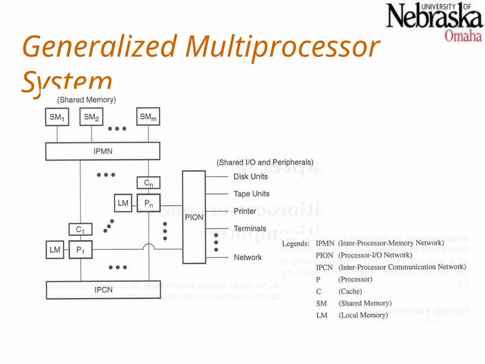
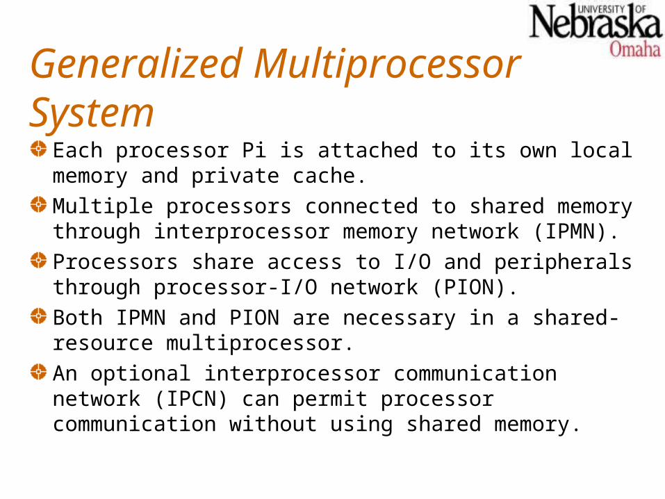
Each processor Pi is attached to its own local memory and private cache.Multiple processors connected to shared memory through interprocessor memory network (IPMN).Processors share access to I/O and peripherals through processor-I/O network (PION).Both IPMN and PION are necessary in a shared-resource multiprocessor.An optional interprocessor communication network (IPCN) can permit processor communication without using shared memory.
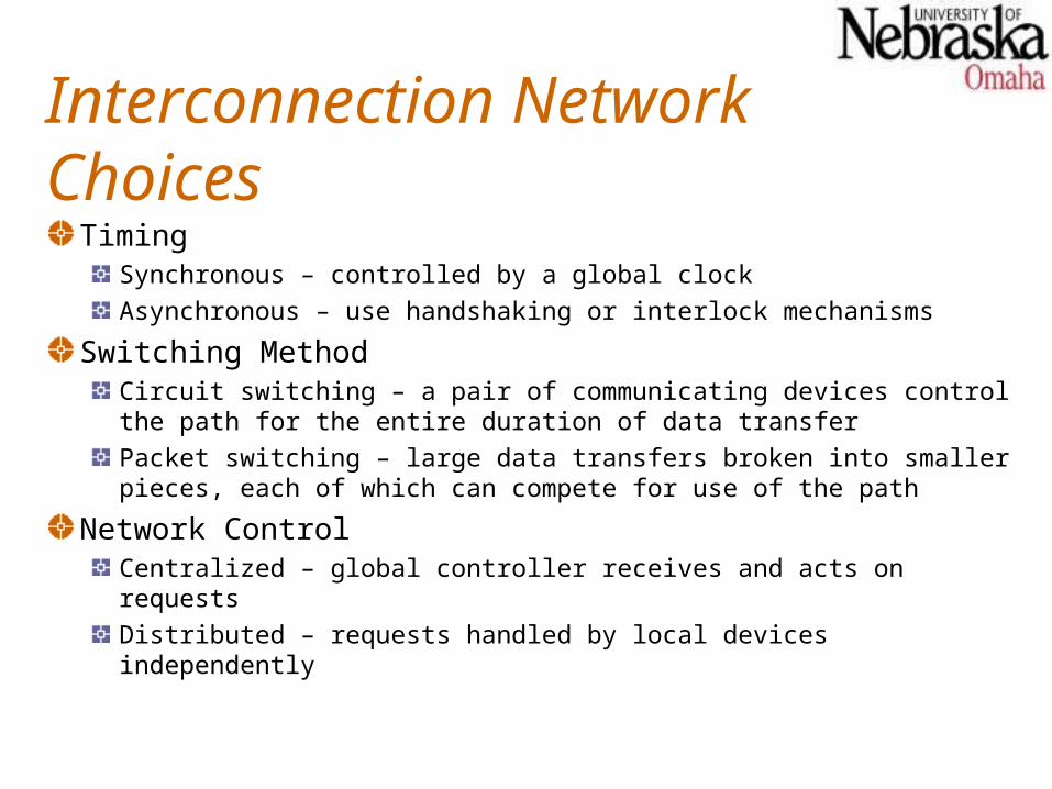
Interconnection Network ChoicesTiming
Synchronous – controlled by a global clock
Asynchronous – use handshaking or interlock mechanisms
Switching MethodCircuit switching – a pair of communicating devices control the path for the entire duration of data transfer
Packet switching – large data transfers broken into smaller pieces, each of which can compete for use of the path
Network ControlCentralized – global controller receives and acts on requests
Distributed – requests handled by local devices independently
Digital Buses
Digital buses are the fundamental interconnects adopted in most commercial multiprocessor systems with less than 100 processors.The principal limitation to the bus approach is packaging technology.Complete bus specifications include logical, electrical and mechanical properties, application profiles, and interface requirements.
Bus SystemsA bus system is a hierarchy of buses connection various system and subsystem components.Each bus has a complement of control, signal, and power lines.There is usually a variety of buses in a system:
Local bus – (usually integral to a system board) connects various major system components (chips)Memory bus – used within a memory board to connect the interface, the controller, and the memory cellsData bus – might be used on an I/O board or VLSI chip to connect various componentsBackplane – like a local bus, but with connectors to which other boards can be attached
Hierarchical Bus Systems
There are numerous ways in which buses, processors, memories, and I/O devices can be organized.One organization has processors (and their caches) as leaf nodes in a tree, with the buses (and caches) to which these processors connect forming the interior nodes.This generic organization, with appropriate protocols to ensure cache coherency, can model most hierarchical bus organizations.
Bridges
The term bridge is used to denote a device that is used to connect two (or possibly more) buses.The interconnected buses may use the same standards, or they may be different (e.g. PCI and ISA buses in a modern PC).Bridge functions include
Communication protocol conversionInterrupt handlingServing as cache and memory agents
Crossbar Switch and Multiport Memory
Single stage networks are sometimes called recirculating networks because data items may have to pass through the single stage many times.The crossbar switch and the multiported memory organization (seen later) are both single-stage networks.This is because even if two processors attempted to access the same memory module (or I/O device at the same time, only one of the requests is serviced at a time.
Multistage Networks
Multistage networks consist of multiple sages of switch boxes, and should be able to connect any input to any output.A multistage network is called blocking if the simultaneous connections of some multiple input-output pairs may result in conflicts in the use of switches or communication links.A nonblocking multistage network can perform all possible connections between inputs and outputs by rearranging its connections.
Crossbar Networks
Crossbar networks connect every input to every output through a crosspoint switch.A crossbar network is a single stage, non-blocking permutation network.In an n-processor, m-memory system, n m crosspoint switches will be required. Each crosspoint is a unary switch which can be open or closed, providing a point-to-point connection path between the processor and a memory module.
Crosspoint Switch Design
Out of n crosspoint switches in each column of an n m crossbar mesh, only one can be connected at a time.Crosspoint switches must be designed to handle the potential contention for each memory module.Each processor provides a request line, a read/write line, a set of address lines, and a set of data lines to a crosspoint switch for a single column.The crosspoint switch eventually responds with an acknowledgement when the access has been completed.
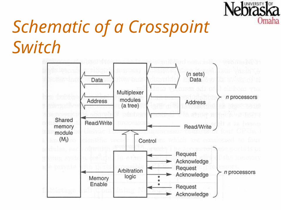
Schematic of a Crosspoint Switch
Multiport Memory
Since crossbar switches are expensive, and not suitable for systems with many processors or memory modules, multiport memory modules may be used instead.A multiport memory module has multiple connections points for processors (or I/O devices), and the memory controller in the module handles the arbitration and switching that might otherwise have been accomplished by a crosspoint switch.
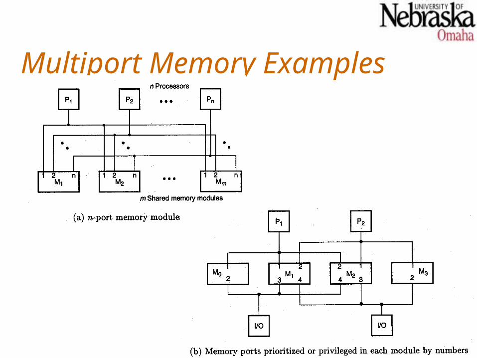
Multiport Memory Examples
Omega Networks
N-input Omega networks, in general, have log2n stages, with the input stage labeled 0.
The interstage connection (ISC) pattern is a perfect shuffle.Routing is controlled by inspecting the destination address. When the i-th highest order bit is 0, the 22 switch in stage i connects the input to the upper output. Otherwise it connects the input to the lower output.
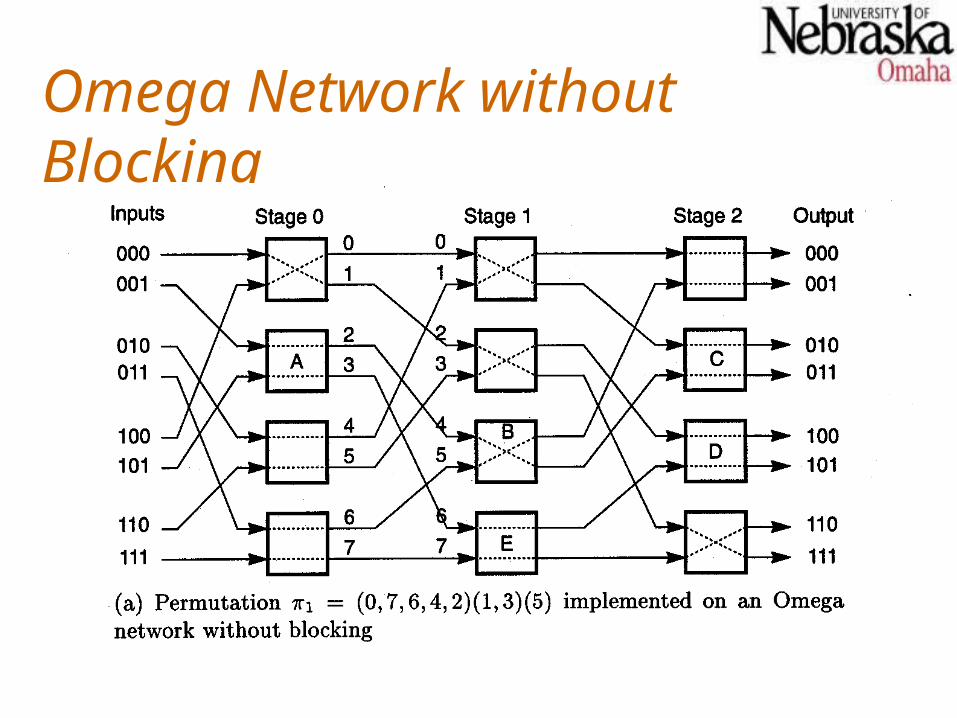
Omega Network without Blocking
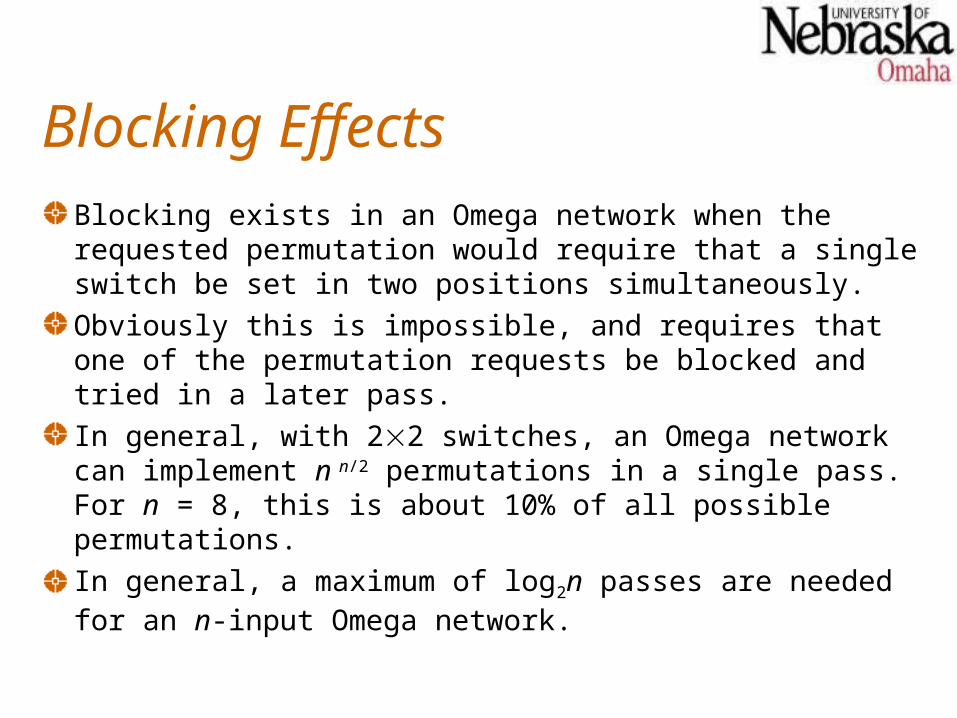
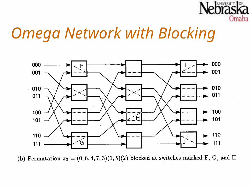
Blocking EffectsBlocking exists in an Omega network when the requested permutation would require that a single switch be set in two positions simultaneously.Obviously this is impossible, and requires that one of the permutation requests be blocked and tried in a later pass.In general, with 22 switches, an Omega network can implement n n/2 permutations in a single pass. For n = 8, this is about 10% of all possible permutations.In general, a maximum of log2n passes are needed for an n-input Omega network.
Omega Network with Blocking
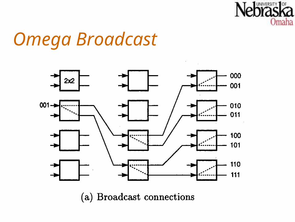
Omega Broadcast
An Omega network can be used to broadcast data to multiple destinations.The switch to which the input is connected is set to the broadcast position (input connected to both outputs).Each additional switch (in later stages) to which an output is directed is also set to the broadcast position.
Omega Broadcast
Larger Switches
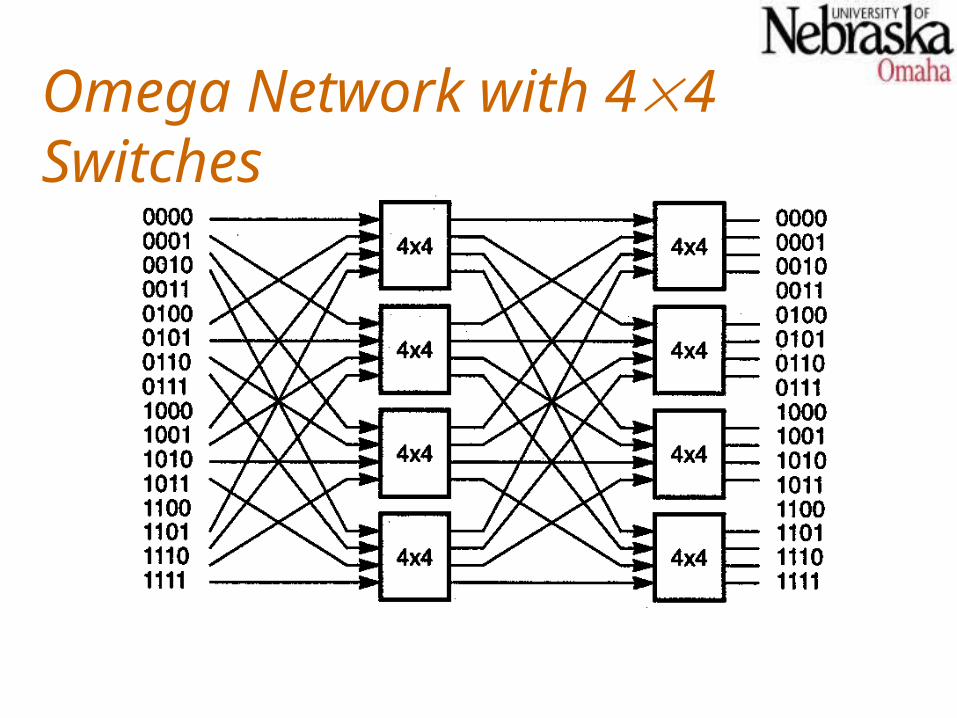
Larger switches (more inputs and outputs, and more switching patterns) can be used to build an Omega network, resulting in fewer stages.For example, with 44 switches, only log416 stages are required for a 16-input switch.A k-way perfect shuffle is used as the ISC for an Omega network using k k switches.
Omega Network with 44 Switches
Butterfly Networks
Butterfly networks are built using crossbar switches instead of those found in Omega networks.There are no broadcast connections in a butterfly network, making them a restricted subclass of the Omega networks.
Hot Spots
When a particular memory module is being heavily accessed by multiple processors at the same time, we say a hot spot exists.For example, if multiple processors are accessing the same memory location with a spin lock implemented with a test and set instruction, then a hot spot may exist.Obviously, hot spots may significantly degrade the network performance.
Dealing With Hot Spots
To avoid the hot spot problems, we may develop special operations that are actually implemented partially by the network.Consider the instruction Fetch&Add(x,e), which has the following definition (x is a memory location, and the returned value is stored in a processor register):
temp xx x + ereturn temp
Implementing Fetch&Add
When n processors attempt to execute Fetch&Add on the same location simultaneously, the network performs a serialization on the requests, performing the following steps atomically.
x is returned to one processor, x+e1 to the next, x+e1+e2, to the next, and so forth.
The value x+e1+e2+…+en is stored in x.
Note that multiple simultaneous test and set instructions could be handled in a similar manner.
The Cost of Fetch&Add
Clearly a feature like Fetch&Add is not available at no cost.Each switch in the network must be built to detect the Fetch&Add requests (distinct from other requests), queuing them until the operation can be atomically completed.Additional switch cycles may be required, increasing network latency significantly.