Embed Size (px)
Citation preview
CSC 634: Networks ProgrammingLecture 03: Review of Basic Networking Concepts (TCP/UDP)
Instructor: Haidar M. Harmanani
Recap
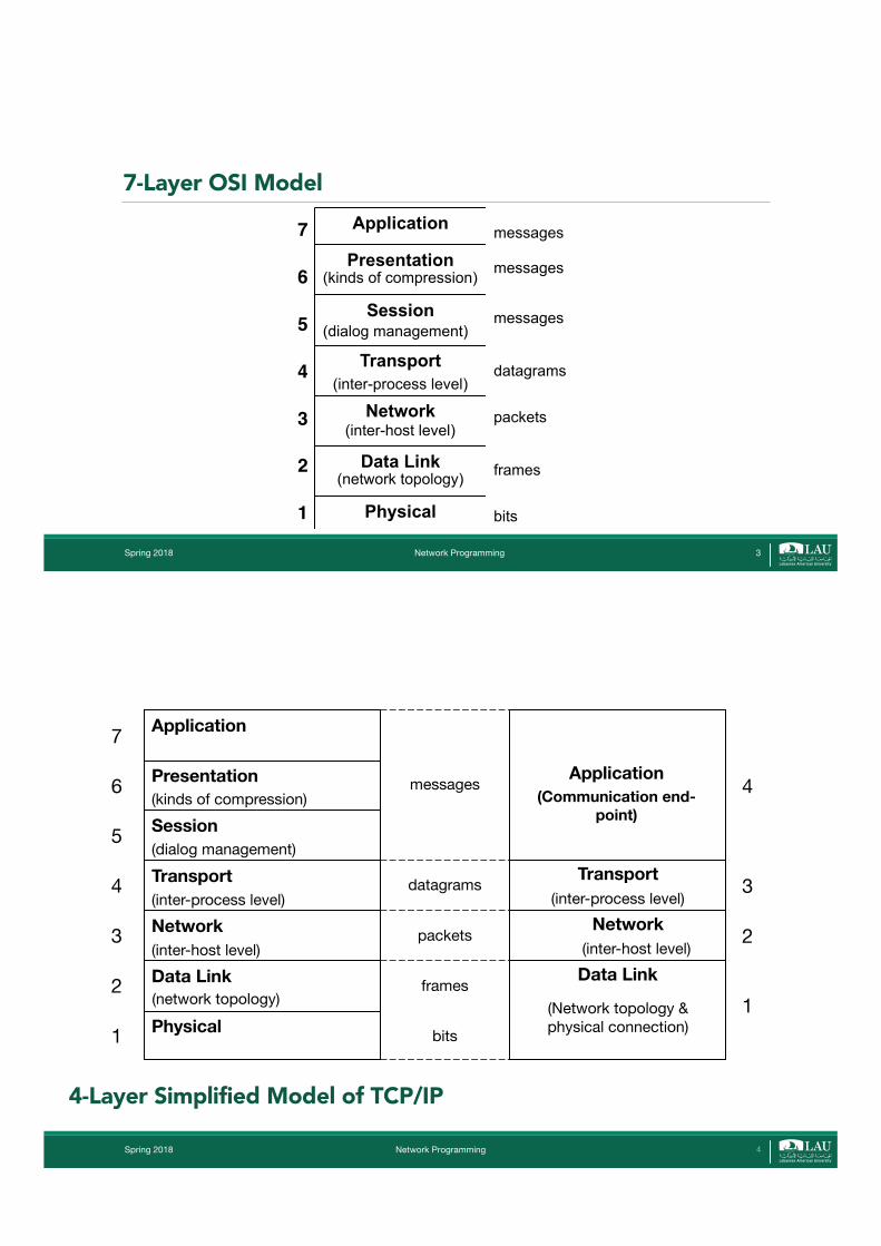
7-Layer OSI Model
Spring 2018 Network Programming
Application
Presentation
Session
Transport
Network
Data Link
Physical
7
6
5
4
3
2
1
(inter-host level)
(inter-process level)
(dialog management)
(kinds of compression)
bits
frames
packets
datagrams
messages
messages
messages
(network topology)
3
Spring 2018 Network Programming
4-Layer Simplified Model of TCP/IP
(inter-host level)
Physical
Data Link
Network
Transport
Session
Presentation
Application7
6
5
4
3
2
1
(inter-host level)
(inter-process level)
(dialog management)
(kinds of compression)
bits
frames
packets
datagrams
messages
(network topology)Data Link
Transport
Application(Communication end-
point)
4
3
2
1
(inter-process level)
(Network topology & physical connection)
Network
4

Spring 2018 Network Programming
Communication Networks can be divided into two basic types by method of data transmission: circuit-switched and packet-switched.
Circuit-Switched Data Transmission
Packet-Switched Data Transmission
hop hop hop hop hop
circuit
The TCP/IP Internet uses packet-switched data transmission,
provided by IP (Network) layer, responsible for
forwarding of IP packets.
• Shared communication links are used instead of dedicated line• Information is divided into pieces – packets. • Each packet contains the address of destination and separately routed over shared
data links.
• Non-shared dedicated communication line is established• Information transmitted without division• Connection established once, then all data transmitted through this connection.
Data Transmission Method
5
Network Programming
Multiplexing and Demultiplexing in TCP/IP Example.
Process 1 Process 2 Process 3 Process 4
UDP TCP
IP
Multi-homed Multi-user Host
Ethernetinterface
Ethernetinterface
Ethernet cable 1
Ethernet cable 2
TCP/IP Suite XNS Suite
Process 5
Multiplexing means “to combine many into one”. For network this means combining of data accepted from different functionalities of neighbor layer.Demultiplexing is reverse of multiplexing.
Multiplexing
Demultiplexing
Spring 2018 6
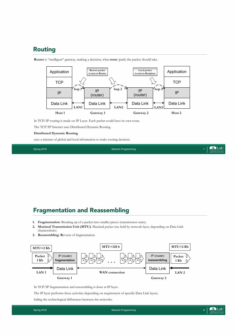
Routing
Network Programming
Router is “intelligent” gateway, making a decision, what route (path) the packet should take.
Data Link
IP
TCP
Application
Data Link
IP
TCP
Application
Data Link
IP(router)
Data Link
IP (router)
LAN1 LAN2 LAN3Gateway 1 Gateway 2Host 1 Host 2
hop 1 hop 2 hop 3
Remote packetis sent to Router
Local packetis sent to Recipient
In TCP/IP routing is made on IP Layer. Each packet could have its own route.
The TCP/IP Internet uses Distributed Dynamic Routing.
Distributed Dynamic Routing
uses a mixture of global and local information to make routing decision.
Spring 2018 7
Fragmentation and Reassembling
Network Programming
1. Fragmentation: Breaking up of a packet into smaller pieces (transmission units).2. Maximal Transmission Unit (MTU): Maximal packet size held by network layer, depending on Data Link
characteristics3. Reassembling: Reverse of fragmentation.
Data Link
IP (router)fragmentation
Data Link
IP (router)reassembling
LAN 1 WAN connection LAN 2
Gateway 1 Gateway 2
MTU=2 Kb MTU=2 KbMTU=128 b
Packet 1 Kb
Packet 1 Kb
128b
128b
128b
128b
128b
128b
In TCP/IP fragmentation and reassembling is done at IP layer.
The IP layer performs these activities depending on requirement of specific Data Link layers,
hiding the technological differences between the networks.
. . .
Spring 2018 8
Part II: Transport Layer
Spring 2018 Network Programming
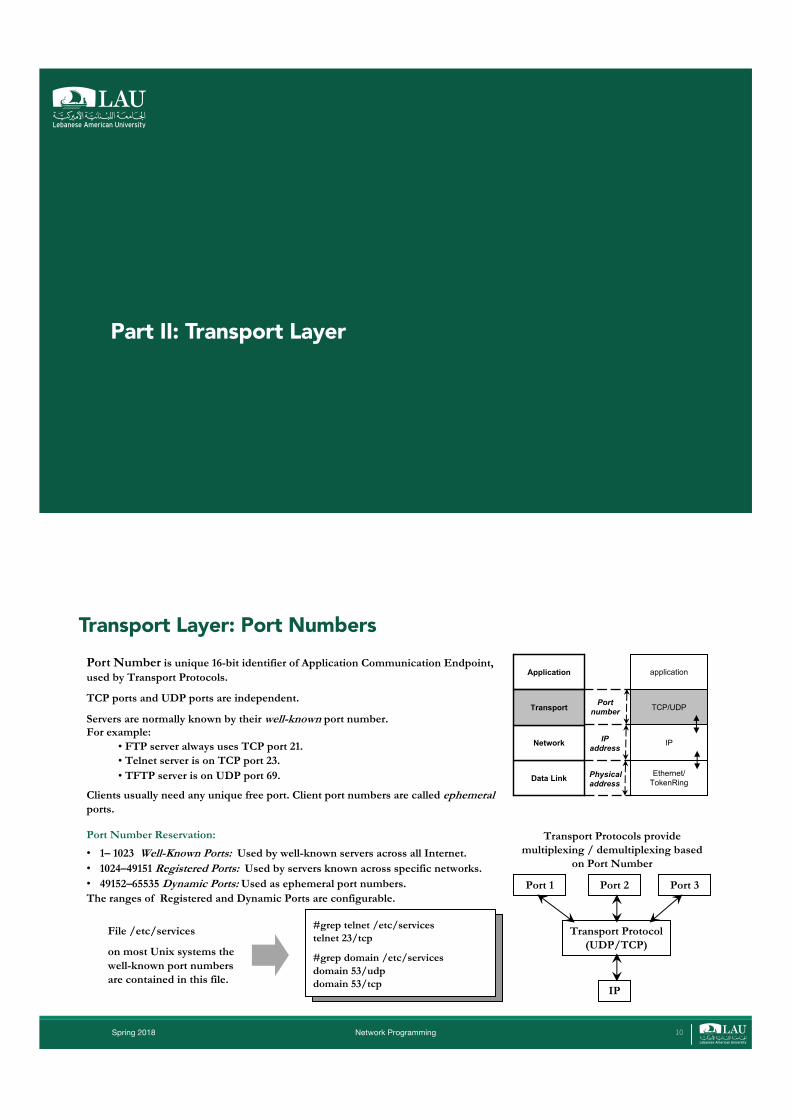
Transport Layer: Port Numbers
Ethernet/ TokenRing
IP
TCP/UDP
application
Data Link
Network
Transport
Application
Physical address
IP address
Port number
Port Number is unique 16-bit identifier of Application Communication Endpoint, used by Transport Protocols.
TCP ports and UDP ports are independent.
Servers are normally known by their well-known port number. For example:
• FTP server always uses TCP port 21. • Telnet server is on TCP port 23. • TFTP server is on UDP port 69.
Clients usually need any unique free port. Client port numbers are called ephemeralports.
Port Number Reservation:
• 1– 1023 Well-Known Ports: Used by well-known servers across all Internet.• 1024–49151 Registered Ports: Used by servers known across specific networks.• 49152–65535 Dynamic Ports: Used as ephemeral port numbers.The ranges of Registered and Dynamic Ports are configurable.
Port 1 Port 2 Port 3
Transport Protocol(UDP/TCP)
IP
Transport Protocols provide multiplexing / demultiplexing based
on Port Number
File /etc/services
on most Unix systems the well-known port numbers are contained in this file.
10
#grep telnet /etc/services telnet 23/tcp
#grep domain /etc/servicesdomain 53/udpdomain 53/tcp
Spring 2018 Network Programming
Association and Transport Address
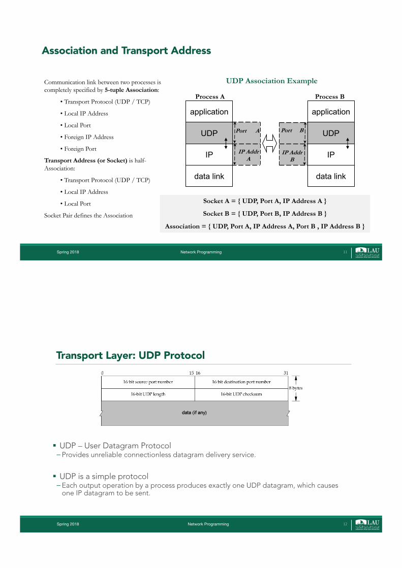
Communication link between two processes is completely specified by 5-tuple Association:
• Transport Protocol (UDP / TCP)
• Local IP Address
• Local Port
• Foreign IP Address
• Foreign Port
Transport Address (or Socket) is half-Association:
• Transport Protocol (UDP / TCP)
• Local IP Address
• Local Port
Socket Pair defines the Association
UDP Association Example
Socket A = { UDP, Port A, IP Address A }
Socket B = { UDP, Port B, IP Address B }
Association = { UDP, Port A, IP Address A, Port B , IP Address B }
11
data link
IP
UDP
application
IP AddrB
Port B
data link
IP
UDP
application
IP AddrA
Port A
Process A Process B
Transport Layer: UDP Protocol
§ UDP – User Datagram Protocol� Provides unreliable connectionless datagram delivery service.
§ UDP is a simple protocol� Each output operation by a process produces exactly one UDP datagram, which causes
one IP datagram to be sent.
Spring 2018 Network Programming 12

Transport Layer: UDP Protocol
§ Source and Destination Port Numbers� Identify the sending process and the receiving process
§ UDP length� The length of the UDP header and the UDP data in bytes. � Can be calculated from IP header
§ UDP checksum� Covers the UDP Pseudo-Header (see below) and the UDP data.
§ In order to double-check that the data has arrived at the correct destination, the UDP checksum is calculated on UDP Pseudo-Header, containing:� UDP header itself� IP Header fields: Source IP Address, Destination IP Address, Protocol type.
§ DATA field may be empty
Spring 2018 Network Programming 13
Reliable Stream Transport: TCP§ Computer communication networks provide unreliable packet delivery� Packets maybe lost, destroyed, duplicated, delivered out of order or after a delay
§ At high level, application programs send a large volume of data from one computer to the next�Hard to use unreliable connectionless delivery� Programmers have to build error detection and recovery into each application program
Spring 2018 Network Programming 14

Reliable Stream Transport: TCP§ TCP is remarkable since it solves a difficult problem well�No other protocol has proved to work better
§ TCP has various properties�Connection Orientedo An application must first request a connection to a destination
� Point to Point Communicationo A TCP connection has two endpoints
�Complete Reliabilityo Data sent across a connection will be delivered exactly as sent
� Full Duplex Communicationo A TCP connection allows data to flow in either direction
Spring 2018 Network Programming 15
Reliable Stream Transport: TCP§ TCP has various properties (Cont.)� Stream Interfaceo An application sends a continous sequence of octets across a connection
� Reliable Connection Startupo Two applications that create a connection must agree to the new connection
�Graceful Connection Shutdowno An application can open a connection, send data, an then request to shutdown the connection
Spring 2018 Network Programming 16
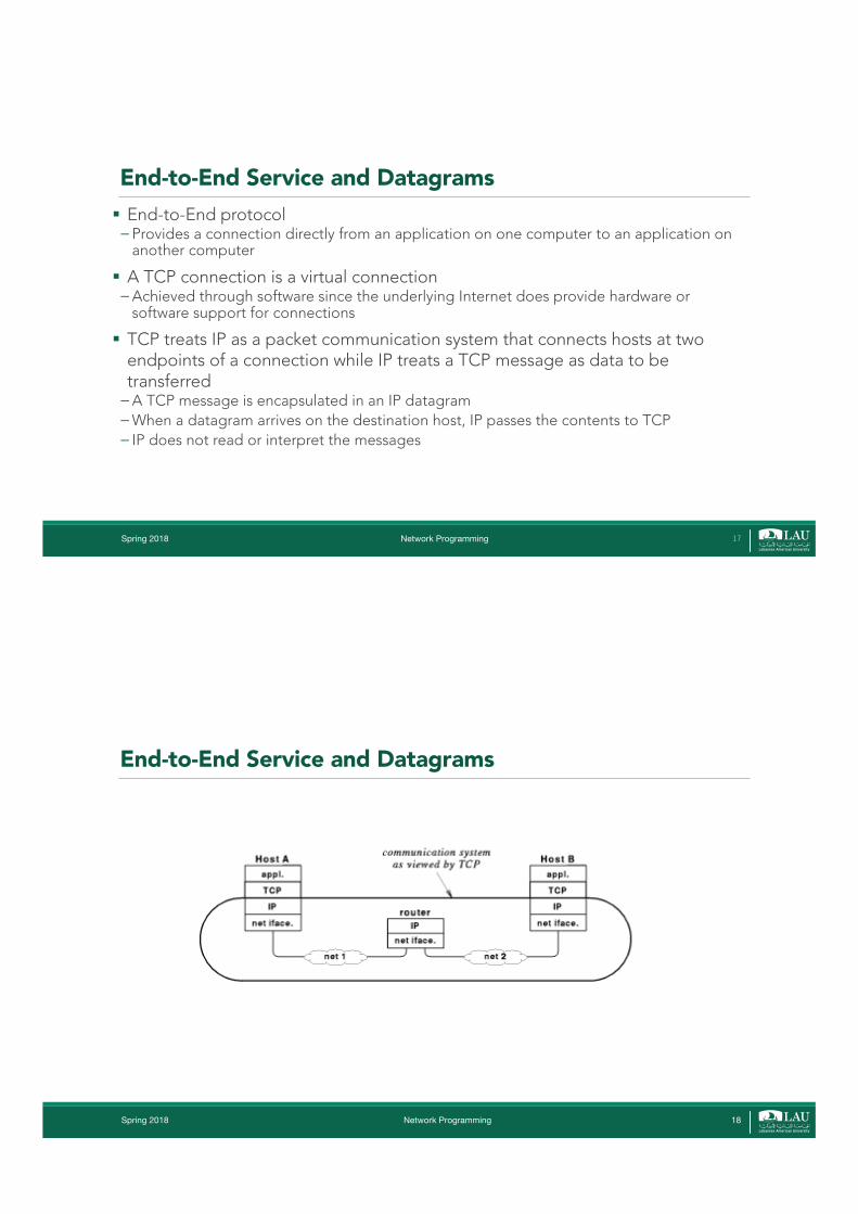
End-to-End Service and Datagrams§ End-to-End protocol� Provides a connection directly from an application on one computer to an application on
another computer
§ A TCP connection is a virtual connection�Achieved through software since the underlying Internet does provide hardware or
software support for connections
§ TCP treats IP as a packet communication system that connects hosts at two endpoints of a connection while IP treats a TCP message as data to be transferred�A TCP message is encapsulated in an IP datagram �When a datagram arrives on the destination host, IP passes the contents to TCP� IP does not read or interpret the messages
Spring 2018 Network Programming 17
End-to-End Service and Datagrams
Spring 2018 Network Programming 18

Flow of TCP segments
Spring 2018 Network Programming 19
Achieving Reliability§ Major problems�Unreliable delivery by the underlying communication system�Computer system reboot
§ The first problem is obvious since packets may be duplicated, lost, delayed, or delivered out of order
§ Computer reboot is another difficult problem� If a connection is established and one computer is rebooted is a problem since the
protocol software on the computer that did not reboot considers the connection to be valid
�Must be able to reject packets from a previous reboot
Spring 2018 Network Programming 20
Achieving Reliability§ TCP converts the unreliable, best effort service of IP into a reliable service� It ensures that each segment is delivered correctly, only once and in order
§ Converting an unreliable connection into a reliable connection is basically the same problem at the data link layer, and essentially the same solution is used:� TCP numbers each segment and uses an ARQ protocol to recover lost segments. � Some versions of TCP implement Go Back N and other versions implement Selective
Repeat.
Spring 2018 Network Programming 21
Transport Layer: TCP – Transmission Control Protocol§ Provides reliable connection-oriented full-duplex byte stream service over unreliable
connectionless packet-switched IP Network
§ TCP provides reliability by doing the following: � The application data is broken into TCP Segments – the best sized chunks passed by TCP to IP.� Each TCP Segment has its Sequence Number.� When TCP receives data from the other end of the connection, it sends an Acknowledgment.� When TCP sends a segment it maintains a Timer. If an acknowledgment isn't received in time, the
segment is retransmitted. � TCP maintains a Checksum on its header and data. If a segment arrives with an invalid checksum,
TCP discards and doesn't acknowledge it, expecting the retransmission from sender after expiration of its timeout.
� TCP Re-Sequences the data if necessary, passing the received data in the correct order to the application.
� TCP provides discarding of duplicate data. � TCP provides Flow Control. Each end of a TCP connection has a finite amount of buffer space. A
receiving TCP allows the sender to send as much data as the receiver has buffers for.
Spring 2018 Network Programming 22
TCP§ However, there are a few important differences between the transport layer and
the data link layer. �At the data link layer, we view a protocol as being operated between two nodes connected
by a point-to-point link. �At the transport layer, this protocol is implemented between two hosts connected
over network. o Packets can arrive out-of-order, and packets may also be stored in buffers within the network and then arrive
at much later times. o The round-trip time will change with different connections and connection establishment is more complicated.
Spring 2018 Network Programming 23
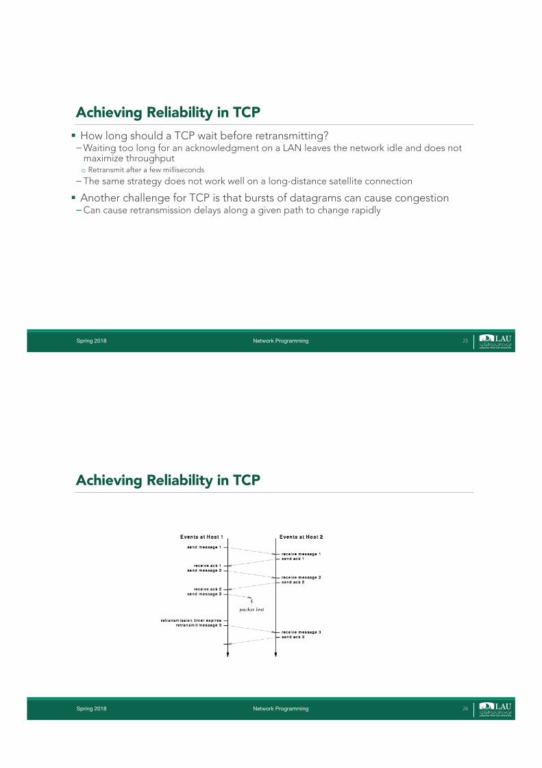
Achieving Reliability in TCP§ Use a positive acknowledgment with retransmission� Recipient communicate with sourceo Send back an acknowledgment message as data is received
� Sender keeps a record of packets it sends and waits for an acknowledgment before sending the next packetso Start a timer when a packet is sento Retransmit if timer expires before an acknowledgment is receivedo Duplicate packets are detected by assigning each packet a sequence number and requiring the receiver to
indicate which sequence numbers it has received
Spring 2018 Network Programming 24
Achieving Reliability in TCP§ How long should a TCP wait before retransmitting?�Waiting too long for an acknowledgment on a LAN leaves the network idle and does not
maximize throughputo Retransmit after a few milliseconds
� The same strategy does not work well on a long-distance satellite connection
§ Another challenge for TCP is that bursts of datagrams can cause congestion�Can cause retransmission delays along a given path to change rapidly
Spring 2018 Network Programming 25
Achieving Reliability in TCP
Spring 2018 Network Programming 26
Adaptive Retransmission§ TCP uses an adaptive retransmission mechanism�Monitor current delay on each connection and change the retransmission timer to
accommodate changing conditions
§ How can TCP estimate the retransmission timeout?� Estimate the round trip delay for a connectiono Whenever a message is sent to which a response is expected, TCP record the time at which the message was sento When a response is received, TCP subtracts the time the message was sent from the current time
�Generate a sequence of round trip estimateso TCP uses a statistical function to produce a weighted averageo TCP estimates of the variance and uses a linear combination of the estimated mean and variance as a value for
retransmission
Spring 2018 Network Programming 27
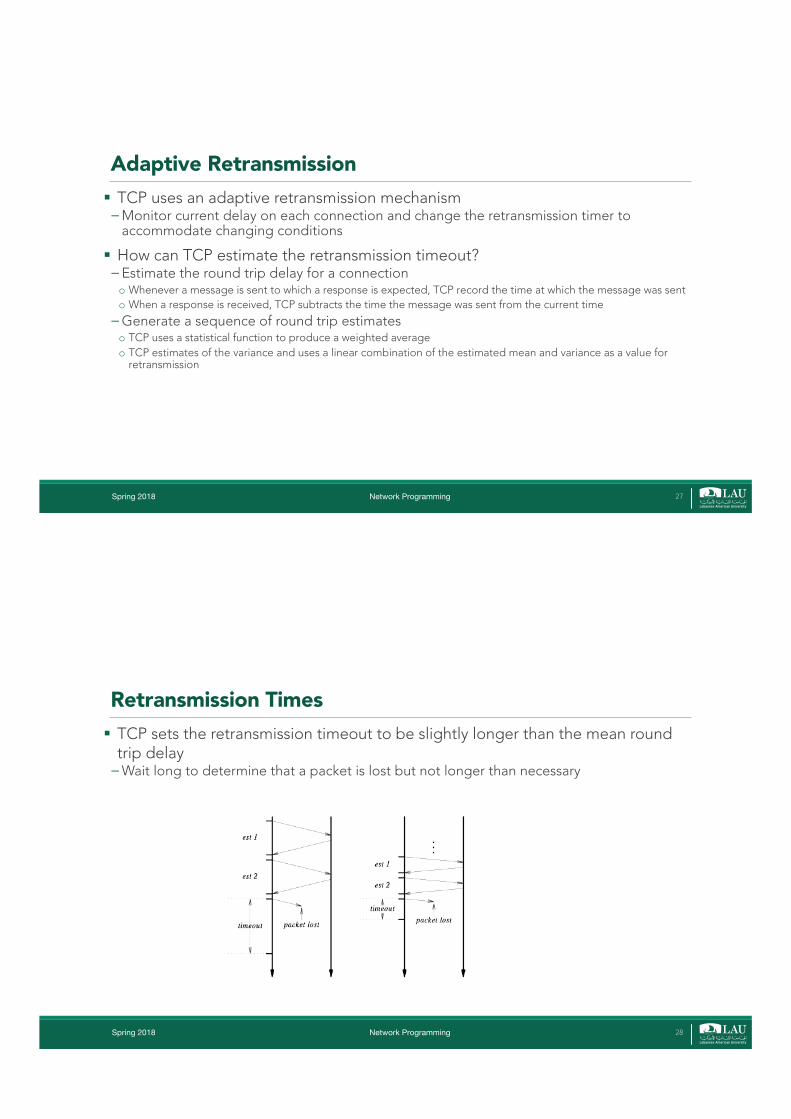
Retransmission Times§ TCP sets the retransmission timeout to be slightly longer than the mean round
trip delay�Wait long to determine that a packet is lost but not longer than necessary
Spring 2018 Network Programming 28
Sliding Windows§ A simple positive acknowledgement protocol wastes substantial amount of
network bandwidth�Must delay sending a new packet until an acknowledgment is received for the previous
packet
§ Use a window mechanism to control the flow of data� Transmit multiple packets before waiting for acknowledgment
§ The protocol places a fixed size window on the sequence of packets and transmits all packets that lie inside the window.�Window slides as long as acknowledgments are received
§ Performance depends on window size and speed at which network accepts packets
Spring 2018 Network Programming 29
Sliding Windows
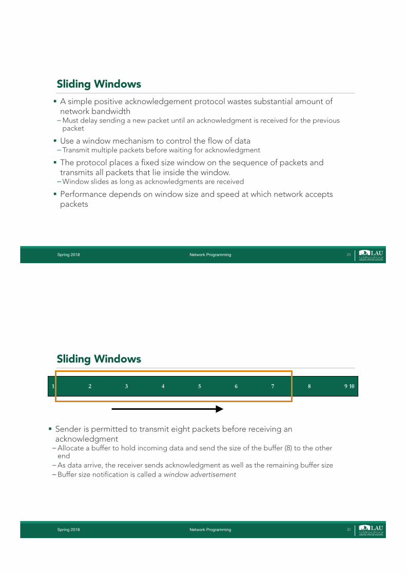
§ Sender is permitted to transmit eight packets before receiving an acknowledgment�Allocate a buffer to hold incoming data and send the size of the buffer (8) to the other
end�As data arrive, the receiver sends acknowledgment as well as the remaining buffer size� Buffer size notification is called a window advertisement
1 2 3 4 5 6 7 8 9 10
Spring 2018 Network Programming 30
Spring 2018 Network Programming 31
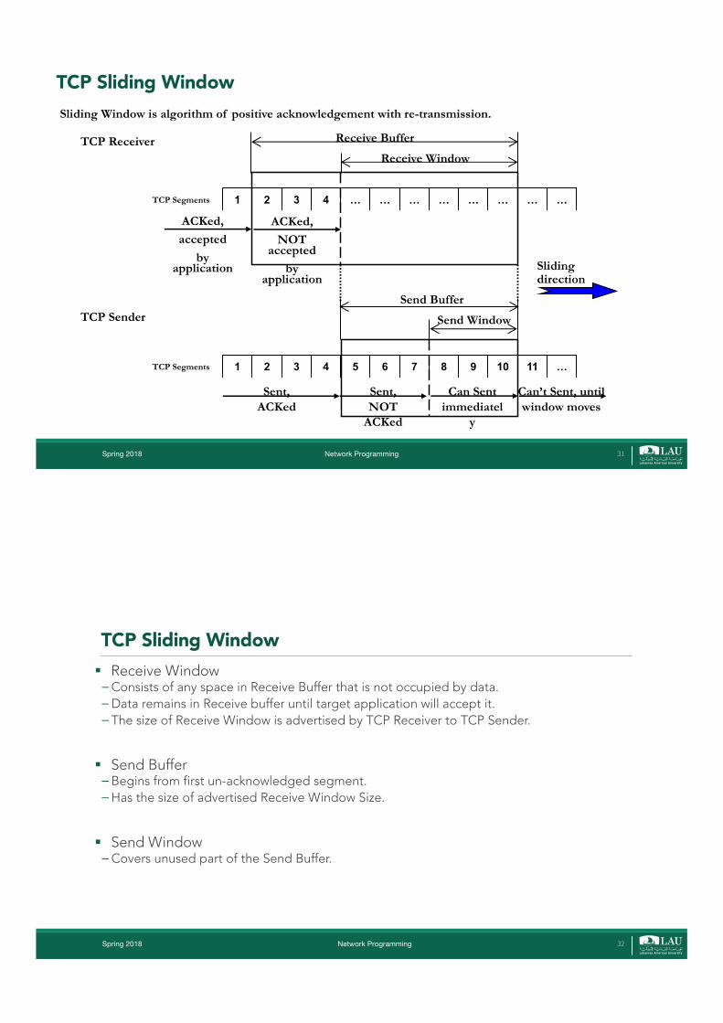
Sliding Window is algorithm of positive acknowledgement with re-transmission.
1 2 3 4 … … … … … … … …
ACKed,accepted
by application
TCP Segments
1 2 3 4 5 6 7 8 9 10 11 …
Sent, ACKed
Sent, NOT
ACKed
Can Sent immediatel
y
Can’t Sent, until window moves
Send Window
Send Buffer
TCP Segments
ACKed,NOT
accepted by
application
Receive Window
Receive BufferTCP Receiver
TCP Sender
Slidingdirection
TCP Sliding Window
TCP Sliding Window§ Receive Window�Consists of any space in Receive Buffer that is not occupied by data.�Data remains in Receive buffer until target application will accept it.� The size of Receive Window is advertised by TCP Receiver to TCP Sender.
§ Send Buffer � Begins from first un-acknowledged segment. �Has the size of advertised Receive Window Size.
§ Send Window�Covers unused part of the Send Buffer.
Spring 2018 Network Programming 32
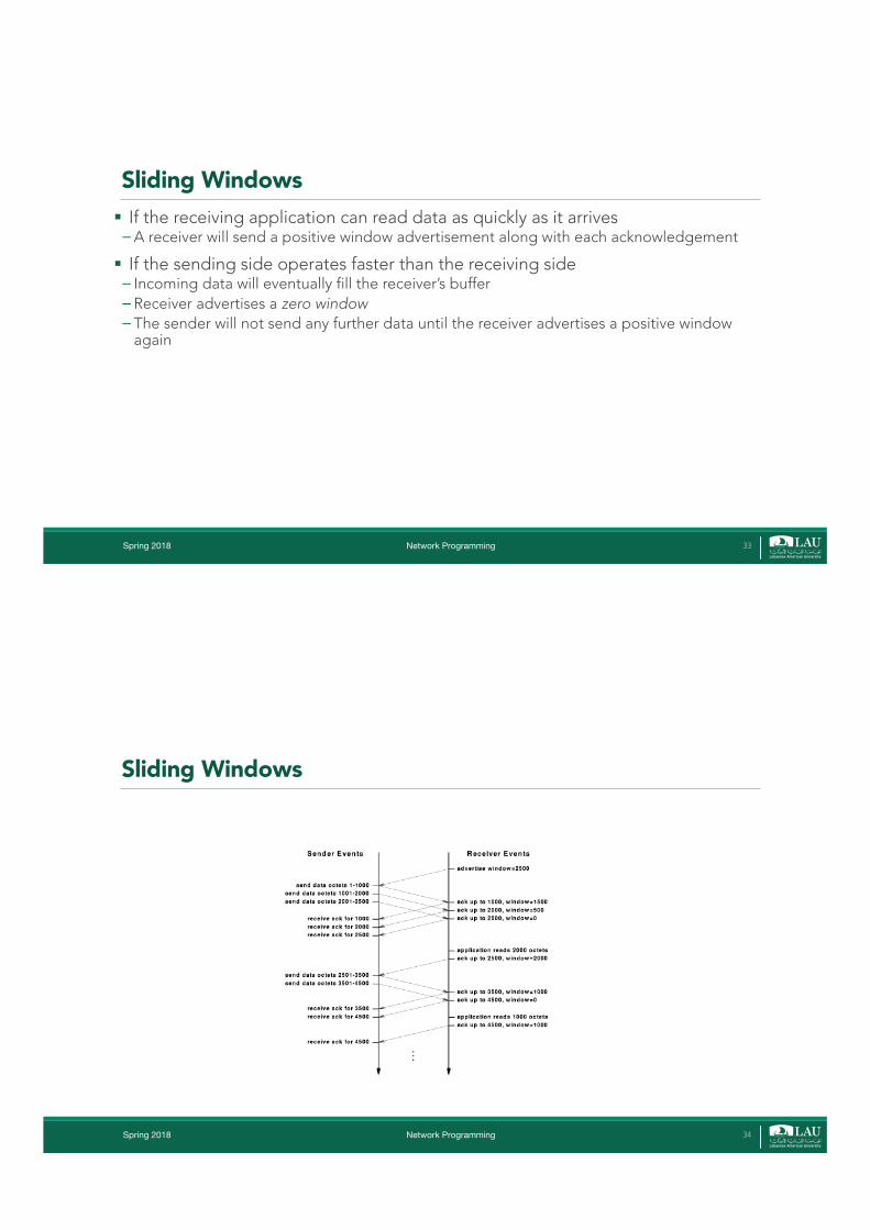
Sliding Windows§ If the receiving application can read data as quickly as it arrives�A receiver will send a positive window advertisement along with each acknowledgement
§ If the sending side operates faster than the receiving side� Incoming data will eventually fill the receiver’s buffer� Receiver advertises a zero window� The sender will not send any further data until the receiver advertises a positive window
again
Spring 2018 Network Programming 33
Sliding Windows
Spring 2018 Network Programming 34
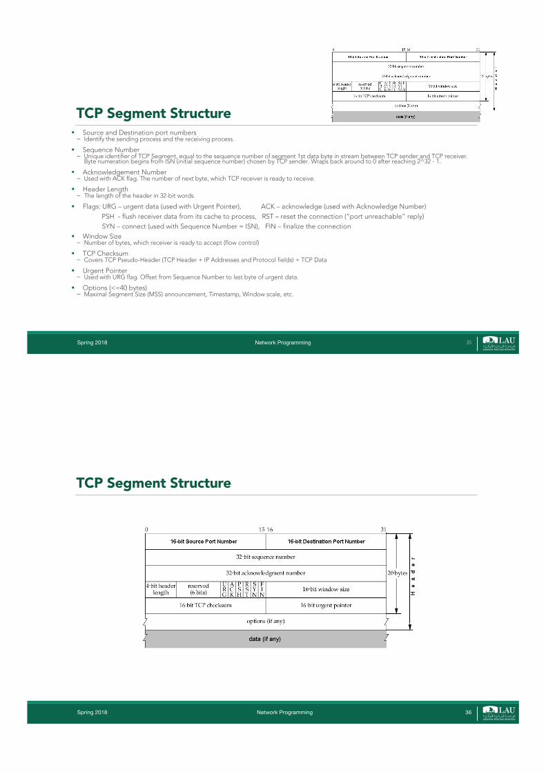
TCP Segment Structure§ Source and Destination port numbers� Identify the sending process and the receiving process.
§ Sequence Number� Unique identifier of TCP Segment, equal to the sequence number of segment 1st data byte in stream between TCP sender and TCP receiver.
Byte numeration begins from ISN (initial sequence number) chosen by TCP sender. Wraps back around to 0 after reaching 2^32 - 1.
§ Acknowledgement Number� Used with ACK flag. The number of next byte, which TCP receiver is ready to receive.
§ Header Length� The length of the header in 32-bit words.
§ Flags: URG – urgent data (used with Urgent Pointer), ACK – acknowledge (used with Acknowledge Number)PSH - flush receiver data from its cache to process, RST – reset the connection (“port unreachable” reply)SYN – connect (used with Sequence Number = ISN), FIN – finalize the connection
§ Window Size� Number of bytes, which receiver is ready to accept (flow control)
§ TCP Checksum� Covers TCP Pseudo-Header (TCP Header + IP Addresses and Protocol fields) + TCP Data
§ Urgent Pointer� Used with URG flag. Offset from Sequence Number to last byte of urgent data.
§ Options (<=40 bytes)� Maximal Segment Size (MSS) announcement, Timestamp, Window scale, etc.
Spring 2018 Network Programming 35
TCP Segment Structure
Spring 2018 Network Programming 36
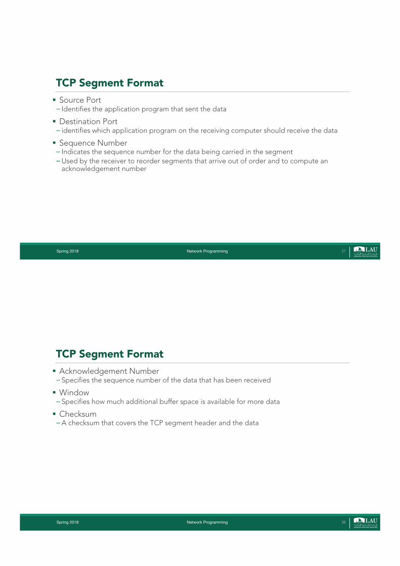
TCP Segment Format§ Source Port� Identifies the application program that sent the data
§ Destination Port� identifies which application program on the receiving computer should receive the data
§ Sequence Number� Indicates the sequence number for the data being carried in the segment�Used by the receiver to reorder segments that arrive out of order and to compute an
acknowledgement number
Spring 2018 Network Programming 37
TCP Segment Format§ Acknowledgement Number� Specifies the sequence number of the data that has been received
§ Window� Specifies how much additional buffer space is available for more data
§ Checksum�A checksum that covers the TCP segment header and the data
Spring 2018 Network Programming 38
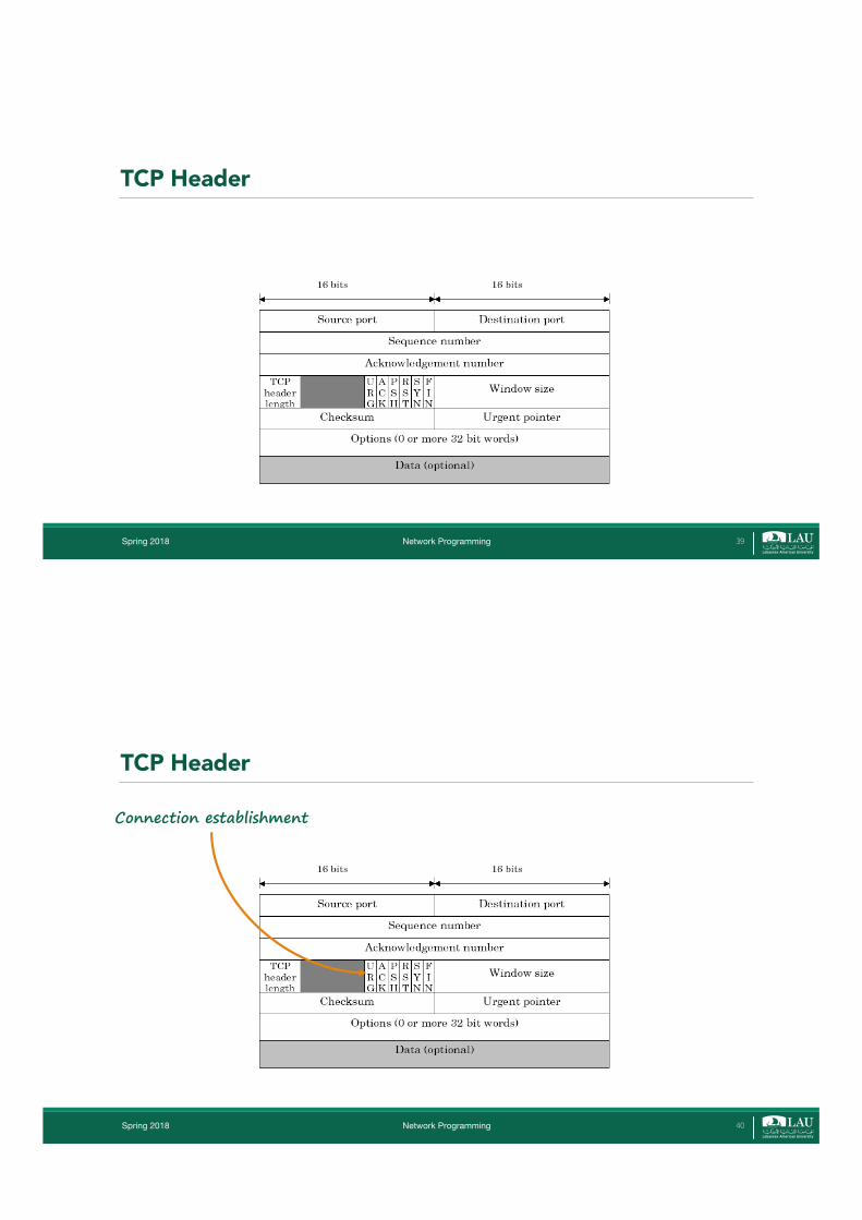
TCP Header
Spring 2018 Network Programming 39
Connection establishment
TCP Header
Spring 2018 Network Programming 40
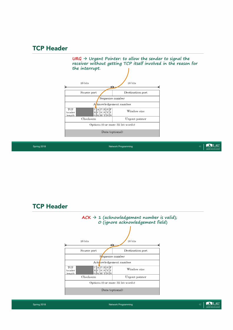
URG à Urgent Pointer: to allow the sender to signal the receiver without getting TCP itself involved in the reason for the interrupt.
TCP Header
Spring 2018 Network Programming 41
ACK à 1 (acknowledgement number is valid); 0 (ignore acknowledgement field)
TCP Header
Spring 2018 Network Programming 42

PSH à PUSHed data: receiver is requested to deliver the data to the application upon arrival and not buffer it.
TCP Header
Spring 2018 Network Programming 43
RST à reset a connection confused due to host crash or some other reason
TCP Header
Spring 2018 Network Programming 44
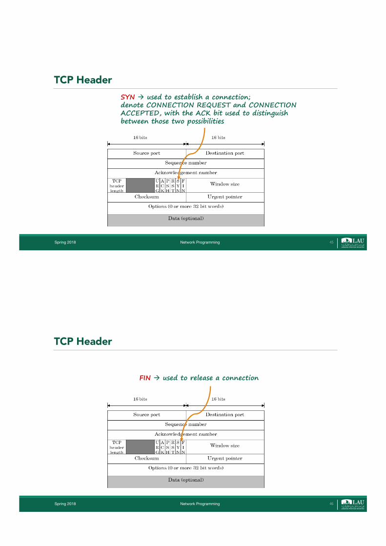
SYN à used to establish a connection; denote CONNECTION REQUEST and CONNECTION ACCEPTED, with the ACK bit used to distinguish between those two possibilities
TCP Header
Spring 2018 Network Programming 45
FIN à used to release a connection
TCP Header
Spring 2018 Network Programming 46
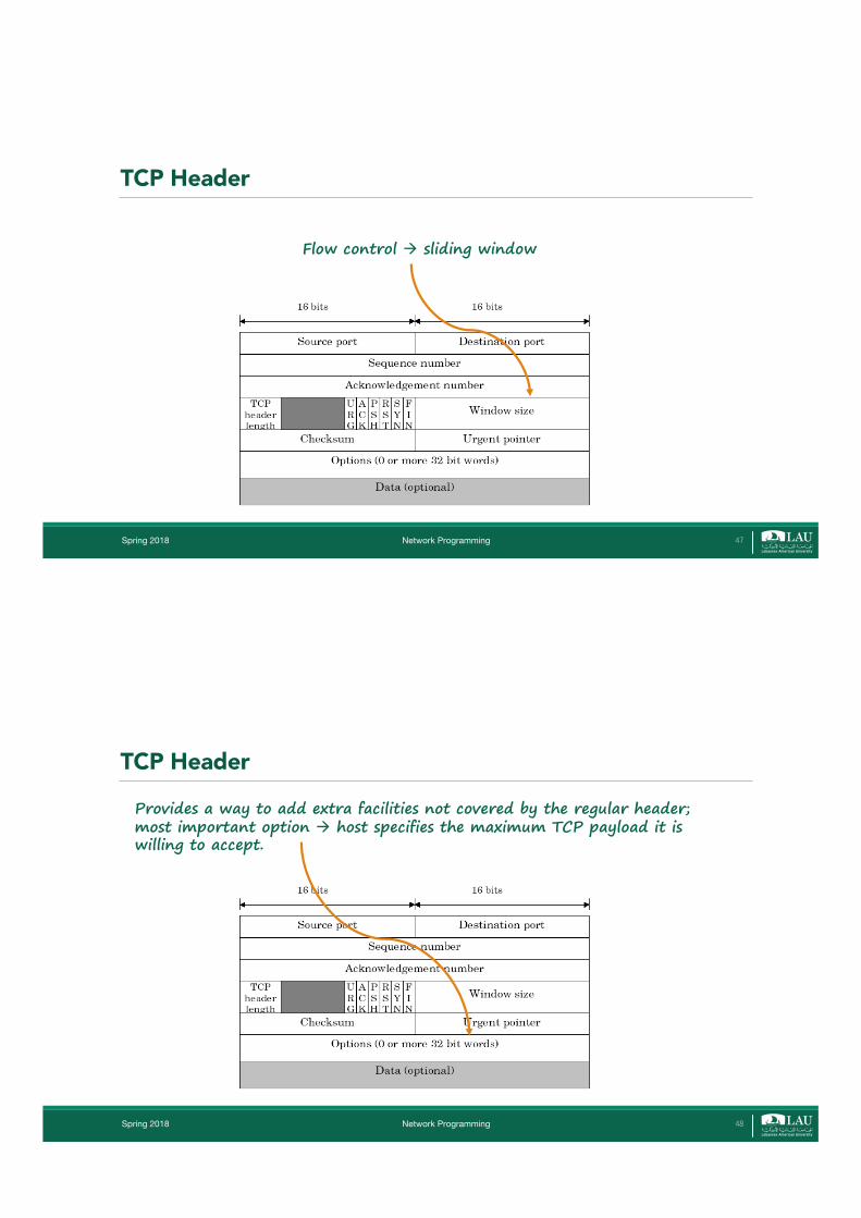
Flow control à sliding window
TCP Header
Spring 2018 Network Programming 47
Provides a way to add extra facilities not covered by the regular header; most important option à host specifies the maximum TCP payload it is willing to accept.
TCP Header
Spring 2018 Network Programming 48
Connection Establishment§ In TCP, a connection establishment phase is required, to ensure that the
receiving process is available and to synchronize sequence numbers, etc.
§ Connection establishment is a basic problem that arises in many other places as well. We look at the generic problem of connection establishment first.
Spring 2018 Network Programming 49
This simple scenario is complicated by the fact that the network can lose, store and re-order packets.
Connection Establishment§ Consider the following simple connection establishment protocol � The client transmits a special packet requesting a connection. � The server responds to a connection request with an accept packet.�After receiving the accept packet the client and server begin sending data using some
ARQ protocol with initial sequence numbers of zero. � If the client does not receive a reply to a connection request after a certain time, it
times-out and retransmits the request.
Spring 2018 Network Programming 50

Example: Suppose the client wants to send one data segment. First it requests a connection, then sends the data and closes the connection. Suppose the client times out after doing each of these steps and then retransmits. This results in the following sequence.
Client Transmits:
CONNECT CONNECT DATA(0) DATA(0) CLOSE CLOSE
Since data can be reordered in the network, the server could receive:
CONNECT DATA(0) CLOSE CONNECT DATA(0) CLOSE
In this case the server may think that the client opened two sessions and sent two different data packets.
Similar problems can arise if a client crashes and then re-opens a connection, while a packet from a previous connection is still in the network.
We will consider some possible solutions to these problems next.
Spring 2018 Network Programming 51
First Solution§ The server could keep track of the last sequence number used for a given
host and assign the next sequence number to start the next connection (this could be sent to the server in the “connection accept” packet).
§ In the previous case, when the server received the second connect, it would tell the client to begin using sequence number 1. In this case when the server receives the second data packet 0 it would know that this was from a previous connection.
Spring 2018 Network Programming 52

Problems§ There are still several problems with the above solution: � This requires the server to store in memory a sequence number for each connection
even after the connection has been released. For large servers this is undesirable. � Even if the server keeps track of sequence numbers, they will eventually “wrap
around” and be reused. If a packet is delayed in the subnet long enough an old packet can still be confused with a new packet that has the same sequence number.
� Either the client or server could crash and loose track of the sequence numbers.
Spring 2018 Network Programming 53
A connection establishment algorithm that avoids the above problems can be designed if the following two assumptions hold
(1) There is a maximum time that packets can be delayed in the subnet. (This type of guarantee must be provided by the network layer, e.g., with the use of the time-to-live field in IP packets.)
(2) Each host has a clock available, which it uses to decide on initial sequence numbers. This clock can be thought of as a counter with N bits, that increments every r seconds (N is the number of bits used for sequence numbers). We assume this clock keeps time even if the host crashes (to avoid the third problem above). These clocks do not need to be synchronized between two different hosts.
Spring 2018 Network Programming 54
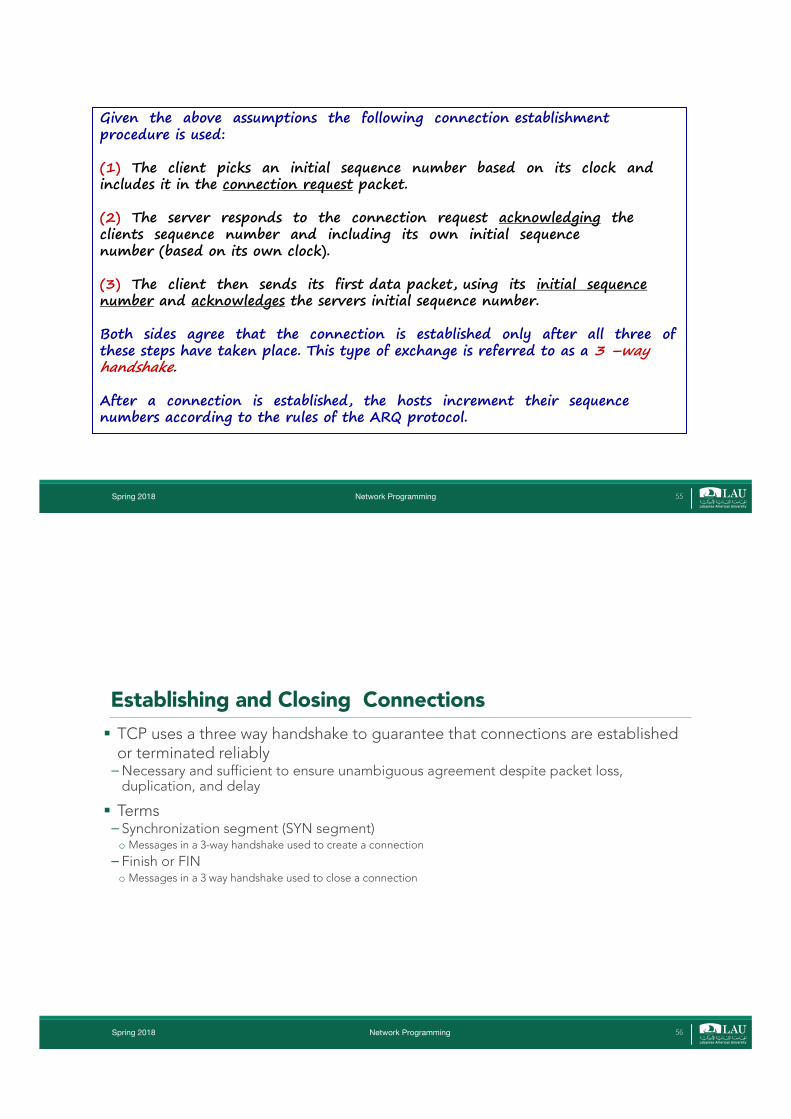
Given the above assumptions the following connection establishment procedure is used:
(1) The client picks an initial sequence number based on its clock and includes it in the connection request packet.
(2) The server responds to the connection request acknowledging the clients sequence number and including its own initial sequence number (based on its own clock).
(3) The client then sends its first data packet, using its initial sequence number and acknowledges the servers initial sequence number.
Both sides agree that the connection is established only after all three of these steps have taken place. This type of exchange is referred to as a 3 –way handshake.
After a connection is established, the hosts increment their sequence numbers according to the rules of the ARQ protocol.
Spring 2018 Network Programming 55
Establishing and Closing Connections§ TCP uses a three way handshake to guarantee that connections are established
or terminated reliably�Necessary and sufficient to ensure unambiguous agreement despite packet loss,
duplication, and delay
§ Terms� Synchronization segment (SYN segment)o Messages in a 3-way handshake used to create a connection
� Finish or FINo Messages in a 3 way handshake used to close a connection
Spring 2018 Network Programming 56
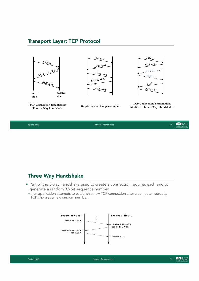
Transport Layer: TCP Protocol
Spring 2018 Network Programming 57
SYN m
SYN n, ACK m+1
ACK n+1
active side
passive side
TCP Connection Establishing.Three – Way Handshake.
FIN m
ACK m+1
ACK n+1
TCP Connection Termination.Modified Three – Way Handshake.
FIN n
ACK n
data n-1
data m
ACK m+1
ACK n+1
Simple data exchange example.
data m+1
data n, ACK
m+2
Three Way Handshake§ Part of the 3-way handshake used to create a connection requires each end to
generate a random 32-bit sequence number� If an application attempts to establish a new TCP connection after a computer reboots,
TCP chooses a new random number
Spring 2018 Network Programming 58

1. A: I would like to talk to you B; A sends a SYN packet to B 2. B: Ok, let's talk; B sends a SYN-ACK packet to A3. A: Thanks; ACK from A to B
Three Way Handshake
Spring 2018 Network Programming 59
Schematically, it looks like this:
Three Way Handshake
Spring 2018 Network Programming 60

What happens if a duplicate CR shows up? The originator is informed as follows:
Avoiding Duplicate Connections
§ The client knows that it has already given up on starting a connection with seq=x. It may tell the server, so that the server does not hold on to false connection (or the server may simply time-out and close the connection.)
Spring 2018 Network Programming 61
Delayed Request and Delayed Third Leg
§ As in the previous example, suppose that both the connection request packet and the first data packet sent from the client were repeated and show up after the connection is closed.
§ In this case, how does the server know to not accept the data?
Spring 2018 Network Programming 62
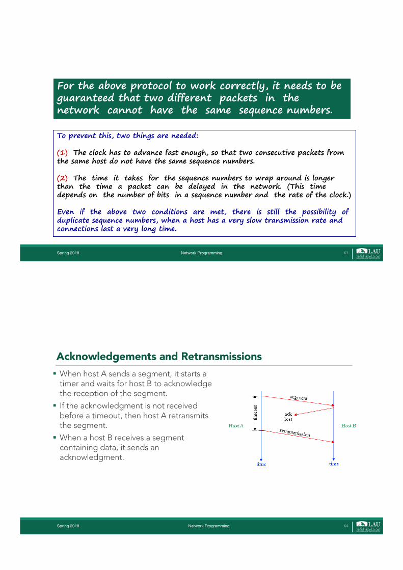
To prevent this, two things are needed:
(1) The clock has to advance fast enough, so that two consecutive packets from the same host do not have the same sequence numbers.
(2) The time it takes for the sequence numbers to wrap around is longer than the time a packet can be delayed in the network. (This time depends on the number of bits in a sequence number and the rate of the clock.)
Even if the above two conditions are met, there is still the possibility of duplicate sequence numbers, when a host has a very slow transmission rate and connections last a very long time.
For the above protocol to work correctly, it needs to be guaranteed that two different packets in the network cannot have the same sequence numbers.
Spring 2018 Network Programming 63
Acknowledgements and Retransmissions§ When host A sends a segment, it starts a
timer and waits for host B to acknowledge the reception of the segment.
§ If the acknowledgment is not received before a timeout, then host A retransmits the segment.
§ When a host B receives a segment containing data, it sends an acknowledgment.
Spring 2018 Network Programming 64
Spring 2018 Network Programming 65
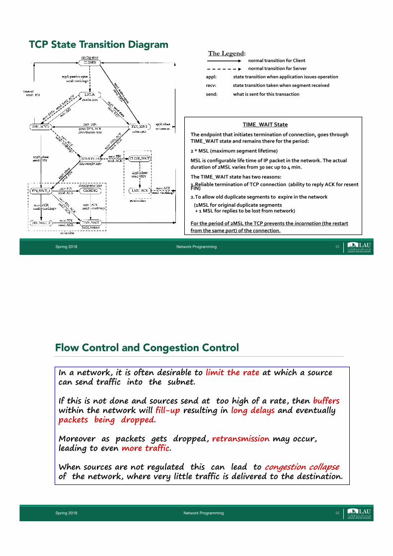
TCP State Transition Diagramnormal transition for Client
normal transition for Server
appl: state transition when application issues operation
recv: state transition taken when segment received
send: what is sent for this transaction
The Legend:
TIME_WAIT State
The endpoint that initiates termination of connection, goes through TIME_WAIT state and remains there for the period:
2 * MSL (maximum segment lifetime)
MSL is configurable life time of IP packet in the network. The actual duration of 2MSL varies from 30 sec up to 4 min.
The TIME_WAIT state has two reasons:1.Reliable termination of TCP connection (ability to reply ACK for resent FIN)
2.To allow old duplicate segments to expire in the network
(1MSL for original duplicate segments + 1 MSL for replies to be lost from network)
For the period of 2MSL the TCP prevents the incarnation (the restart from the same port) of the connection.
In a network, it is often desirable to limit the rate at which a source can send traffic into the subnet.
If this is not done and sources send at too high of a rate, then bufferswithin the network will fill-up resulting in long delays and eventually packets being dropped.
Moreover as packets gets dropped, retransmission may occur, leading to even more traffic.
When sources are not regulated this can lead to congestion collapseof the network, where very little traffic is delivered to the destination.
Flow Control and Congestion Control
Spring 2018 Network Programming 66
Two different factors can limit the rate at which a source sends data.
à the inability of the destination to accept new data.Techniques that address this are referred to as flow control.
à the number of packets within the subnet.Techniques that address this are referred to as congestion control.
Flow Control and Congestion Control
Spring 2018 Network Programming 67
Flow control and congestion control can be addressed at the transport layer, but may also be addressed at other layers.
For example, some DLL protocols perform flow control on each link. And some congestion control approaches are done at the network layer.
Both flow control and congestion control are part of TCP.
Flow Control and Congestion Control
Spring 2018 Network Programming 68
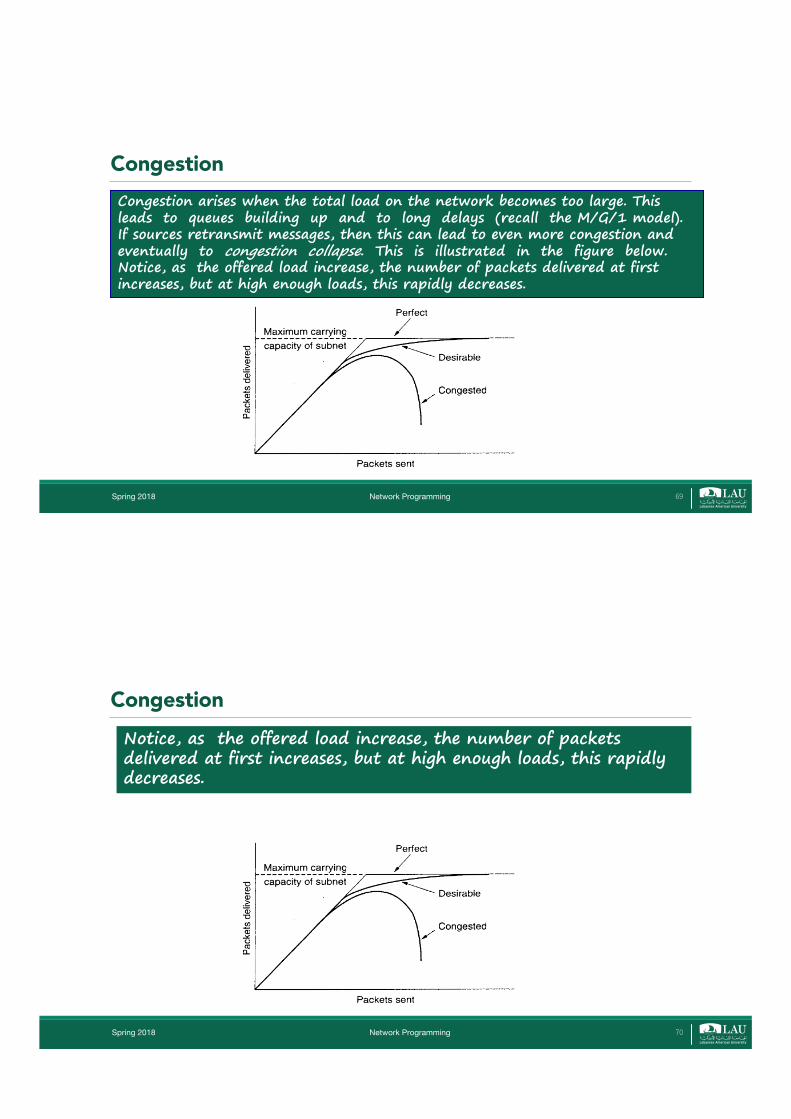
Congestion arises when the total load on the network becomes too large. This leads to queues building up and to long delays (recall the M/G/1 model). If sources retransmit messages, then this can lead to even more congestion and eventually to congestion collapse. This is illustrated in the figure below. Notice, as the offered load increase, the number of packets delivered at first increases, but at high enough loads, this rapidly decreases.
Congestion
Spring 2018 Network Programming 69
Notice, as the offered load increase, the number of packets delivered at first increases, but at high enough loads, this rapidly decreases.
Congestion
Spring 2018 Network Programming 70
For example, originally the Internet (TCP/IP) did not implement congestion control.
This led to a series of congestion collapses starting in 1986.
[V. Jacobson, "Congestion Avoidance and Control", Proc. of SIGCOMM '88.]
To avoid this type of behavior, congestion control was incorporated into TCP.
Spring 2018 Network Programming 71
The first order goal of congestion control is to avoid this type of congestion collapse.
It is still desirable to get the best performance possible. Congestion control can also be used to ensure that users get a desired Quality of Service (QoS) (i.e. throughput, delay).
Also ensuring fairness between different sessions; in other words two sessions with the same requirements should receive equitable treatment from the network. (Exactly what is a fair treatment can be interpreted in several ways.)
Spring 2018 Network Programming 72
Congestion control may be addressed at both the network level and the transport layer.
At the network layer possible approaches include
Packet dropping à when a buffer becomes full a router can drop waiting packets - if not coupled with some other technique, this can lead to greater congestion through retransmissions.
Packet scheduling à certain scheduling policies may help in avoiding congestion - in particular scheduling can help to isolate users that are transmitting at a high rate.
Approaches to Congestion Control
Spring 2018 Network Programming 73
Dynamic routing à when a link becomes congested, change the routing to avoid this link - this only helps up to a point (eventually all links become congested) and can lead to instabilities
Admission control/Traffic policing - Only allow connections in if the network can handle them and make sure that admitted sessions do not send at too high of a rate - only useful for connection-oriented networks.
Approaches to Congestion Control
Spring 2018 Network Programming 74
An approach that can be used at either the network or transport layers is
Rate control à this refers to techniques where the source rate is explicitly controlled based on feedback from either the network and/or the receiver.
For example, routers in the network may send a source a "choke packet" upon becoming congested. When receiving such a packet, the source should lower it rate.
Approaches to Congestion Control
Spring 2018 Network Programming 75
These approaches can be classified as either "congestion avoidance" approaches, if they try to prevent congestion from ever occurring, or as "congestion recovery" approaches, if they wait until congestion occurs and then react to it. In general, “better to prevent than to recover."
Different networks have used various combinations of all these approaches.
Traditionally, rate control at the transport layer has been used in the Internet, but new approaches are beginning to be used that incorporate some of the network layer techniques discussed above.
Approaches to Congestion Control
Spring 2018 Network Programming 76
TCP implements end-to-end congestion control.
IP does not provide any explicit congestion control information; TCP detects congestion via the ACK's from the sliding-window ARQ algorithm used for providing reliable service.
Specifically, assume that the RTT for a session is known, so that the proper time-out time can be used.
When the source times out before receiving an ACK, the most likely reason is because a link became congested. TCP uses this as an indication of congestion. In this case, TCP will slow down the transmission rate.
Congestion Control in TCP
Spring 2018 Network Programming 77
Congestion Control§ Packet loss is most likely to be caused by congestion�Cannot inject additional copies of a message using retransmissiono May reach a state of congestion collapse
§ TCP uses packet loss as a measure of congestion � If a message is lost, TCP begins congestion control� Rather than sending enough data to fill the receiver’s buffero Send a single messageo If ack. is received without loss, TCP doubles the amount of datao If ack. is received without loss, TCP sends four more messageso The exponential increase continues until TCP sends half of the advertised window at which time TCP slows down
the rate of increase
Spring 2018 Network Programming 78
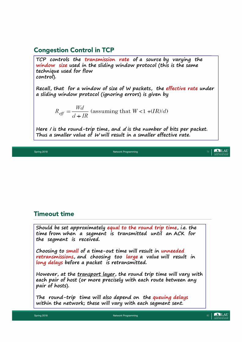
TCP controls the transmission rate of a source by varying the window size used in the sliding window protocol (this is the same technique used for flow control).
Recall, that for a window of size of W packets, the effective rate under a sliding window protocol (ignoring errors) is given by
Here I is the round-trip time, and d is the number of bits per packet. Thus a smaller value of W will result in a smaller effective rate.
Congestion Control in TCP
Spring 2018 Network Programming 79
Should be set approximately equal to the round trip time, i.e. the time from when a segment is transmitted until an ACK for the segment is received.
Choosing to small of a time-out time will result in unneeded retransmissions, and choosing too large a value will result in long delays before a packet is retransmitted.
However, at the transport layer, the round trip time will vary with each pair of host (or more precisely with each route between any pair of hosts).
The round-trip time will also depend on the queuing delayswithin the network; these will vary with each segment sent.
Timeout time
Spring 2018 Network Programming 80

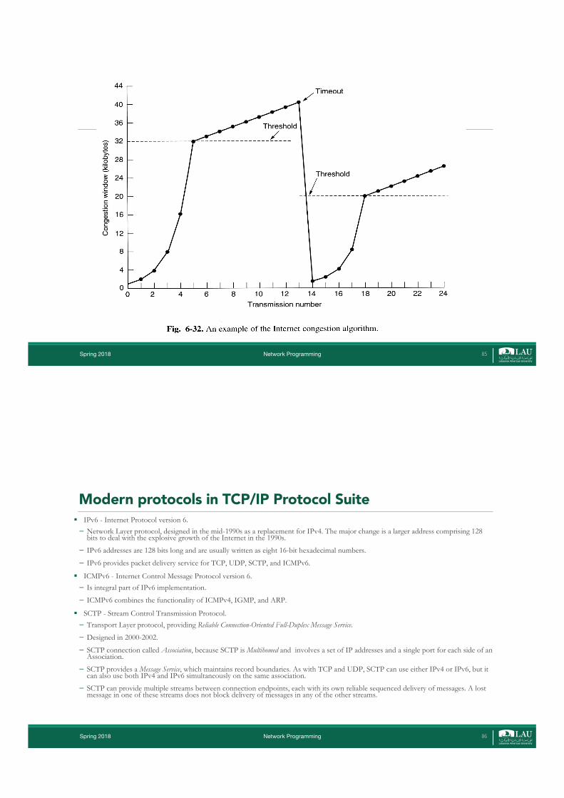
TCP tries to adaptively find the "right" congestion window sizefor the network. If window is too large, network will become congested; if too small then inefficient. More over, the "right" window size may change over time, depending on network load.
When segments are successfully acknowledged, without the sender timing out, TCP increases the window size. Whenever TCP times-out while waiting for a segment it decreases the window size. In this manner TCP continually adapts the window size.
In addition to the congestion window, the sender also keeps track of a parameter called the threshold;
TCP Congestion control
Spring 2018 Network Programming 81
We see that starting at WC = 1, the congestion window will increase by one for every ACK that is received until it becomes larger than the threshold, this phase is called slow start.
After the congestion window becomes larger than the threshold, the congestion window is increased by one for every congestion window worth of ACKs that are received; this phase is called the congestion avoidance phase.
TCP Congestion control
Spring 2018 Network Programming 82
Assume that in approximately one RTT, a congestion window worth of data can be sent and acknowledged (this is reasonable if the time to send a windows worth of data is much less than the RTT).
With this assumption:
à During the slow start phase, the congestion window will double during each RTT, i.e. it will grow exponentially fast.
à During the congestion avoidance phase, the window will increase by 1 during each RTT; in this case, it is growing at a linear rate.
TCP Congestion control
Spring 2018 Network Programming 83
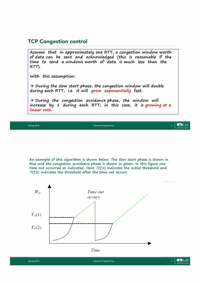
An example of this algorithm is shown below. The slow start phase is shown in blue and the congestion avoidance phase is shown in green. In this figure one time out occurred as indicated. Here TC(1) indicates the initial threshold and TC(2) indicates the threshold after the time out occurs.
Spring 2018 Network Programming 84
Spring 2018 Network Programming 85
Modern protocols in TCP/IP Protocol Suite§ IPv6 - Internet Protocol version 6. � Network Layer protocol, designed in the mid-1990s as a replacement for IPv4. The major change is a larger address comprising 128
bits to deal with the explosive growth of the Internet in the 1990s.
� IPv6 addresses are 128 bits long and are usually written as eight 16-bit hexadecimal numbers.
� IPv6 provides packet delivery service for TCP, UDP, SCTP, and ICMPv6.
§ ICMPv6 - Internet Control Message Protocol version 6. � Is integral part of IPv6 implementation.
� ICMPv6 combines the functionality of ICMPv4, IGMP, and ARP.
§ SCTP - Stream Control Transmission Protocol. � Transport Layer protocol, providing Reliable Connection-Oriented Full-Duplex Message Service.
� Designed in 2000-2002.
� SCTP connection called Association, because SCTP is Multihomed and involves a set of IP addresses and a single port for each side of an Association.
� SCTP provides a Message Service, which maintains record boundaries. As with TCP and UDP, SCTP can use either IPv4 or IPv6, but it can also use both IPv4 and IPv6 simultaneously on the same association.
� SCTP can provide multiple streams between connection endpoints, each with its own reliable sequenced delivery of messages. A lost message in one of these streams does not block delivery of messages in any of the other streams.
Spring 2018 Network Programming 86

Spring 2018 Network Programming 87
Virtual Network and Tunneling: The 6bone.
The 6bone is a virtual network that was created in 1996 for users with islands of IPv6-capable hosts wanted to connect them together using a virtual network without waiting for all the intermediate routers to become IPv6-capable. The 6bone is established on top of the existing IPv4 Internet using tunnels.
TCP/IP Summary§ IPv4� Internet Protocol version 4.
§ IPv6� Internet Protocol version 6.
§ TCP� Transmission Control Protocol.
§ UDP� User Datagram Protocol.
§ SCTP� Stream Control Transmission Protocol.
§ ICMP� Internet Control Message Protocol
� (version 4).
Spring 2018 Network Programming 88
§ IGMP� Internet Group Management Protocol.
§ ARP� Address Resolution Protocol.
§ RARP� Reverse Address Resolution Protocol.
§ ICMPv6� Internet Control Message Protocol version 6.
§ BPF� BSD Packet Filter. Provides access to the datalink layer in
Berkeley-derived kernels.
§ DLPI� Datalink Provider Interface. Provides access to the datalink
layer in System V R4.
Network Programming
What is Internet
Internet
•Set of interconnected independent computer networks. •Uses common suite of protocols called TCP/IP.•Managed by groups of representatives:
• IAB -Internet Activity Board• NIC -National Information Center• FNC -Federal Network Center
Internet ServicesTransport Level:
• Unreliable packet delivery• Reliable stream transport
Application Level:• File Transfer (FTP, TFTP)• Electronic Mail (SMTP)• Remote Login (TELNET)• Network File System (NFS)• Remote Program Execution• Shared peripheral devices
Spring 2018 89
![1 CSC 443: Web Programming - GitHub Pagesharmanani.github.io/classes/csc443/Notes/Lecture02.pdf · History of Internet [8 Minutes] CSC443: Web Programming 5 Brief history (cont.)](https://img.pdfslide.us/doc/110x75/613ffa96b44ffa75b8048f30/1-csc-443-web-programming-github-history-of-internet-8-minutes-csc443-web.jpg)