Embed Size (px)
Citation preview
CSC 395 –Software Engineering
Lecture 13:
Object-Oriented Analysis –or–
Let the Pain Begin (At Least I’m Honest!)
Today’s Goal
Begin discussion OO analysis How do we transition from requirements to code? What can we do to help create reusable designs? Ways to check our analysis How UML helps express these ideas
Analysis Workflow
Translate project to software engineering terms Begins with use-cases and textual descriptions End with a highest-level modules (classes), what
each modules must do, and how they may interact Workflow accomplishes this in two ways:
1. Obtain deeper understanding of the requirements
2. Describe requirements in manner resulting in maintainable design & implementation
For unified process, this is use case driven Everything begins with the use cases
3 “Types” of Classes
Unified Process concept to simplify designs Entity classes hold the long-lived data Boundary classes performs the input & output Control classes do complex processing and
actions “Types” exist only for purposes of design
Need UML stereotypes to display them
Iteratively Extract Classes
1. Functional modelingPresent scenarios of use cases
2. Class modelingFind entity classes and their attributesDetermine their interrelationships and interactionsShow this information using UML class diagrams
3. Dynamic modelingDetermine operations for entity classDisplay information using UML statechart
Scenarios
Use case provides generic description of functionality Scenario scripts one instance of the use case Provides idea of how use case could play out
Study more than one scenario per use case Need comprehensive insight into target product Examining multiple situations reduces chance that
rare condition is overlooked Details skipped here cause impossible-to-find
errors later
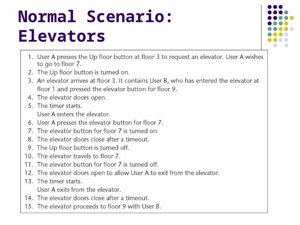
Normal Scenario: Elevators
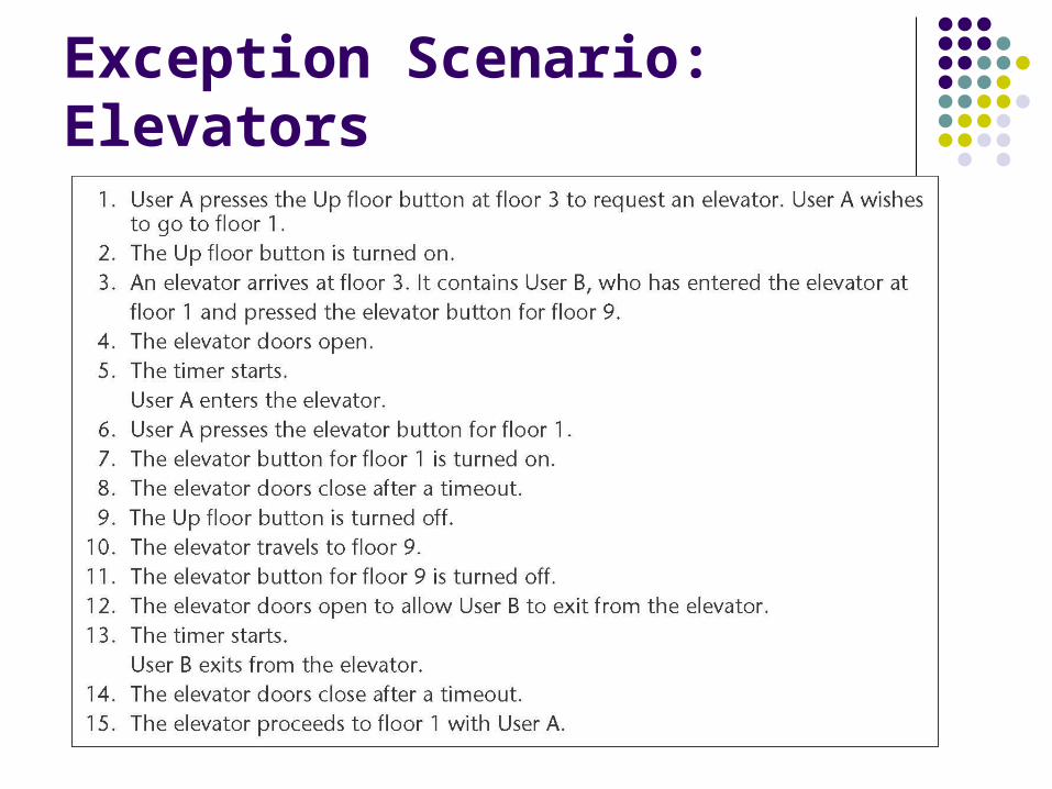
Exception Scenario: Elevators
Entity Class Modeling
Extract classes and their attributes Represent them using a UML class diagram Diagram enables deducing class properties Enables early refinement of class design
Try deducing from use cases and scenarios Risks finding too many candidate classes
Instead use domain knowledge via CRC cards or play English major and use noun extraction But remember, these find candidate classes
Noun Extraction
Initially finds entity class candidates Not all entity classes will be found during initial pass Some classes in early passes will not be used Also provides really good hints as to other classes
Identify nouns in requirements Eliminate classes external to the problem Ignore abstract (non-physical) nouns and those for
communication
Boundary Classes
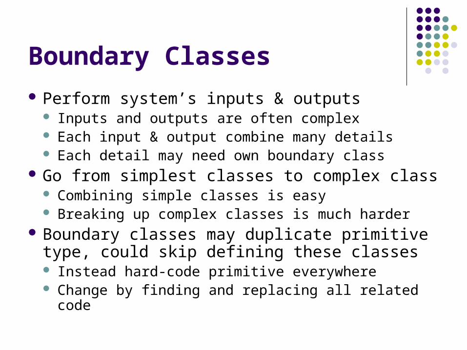
Perform system’s inputs & outputs Inputs and outputs are often complex Each input & output combine many details Each detail may need own boundary class
Go from simplest classes to complex class Combining simple classes is easy Breaking up complex classes is much harder
Boundary classes may duplicate primitive type, could skip defining these classes Instead hard-code primitive everywhere Change by finding and replacing all related code
Control Classes
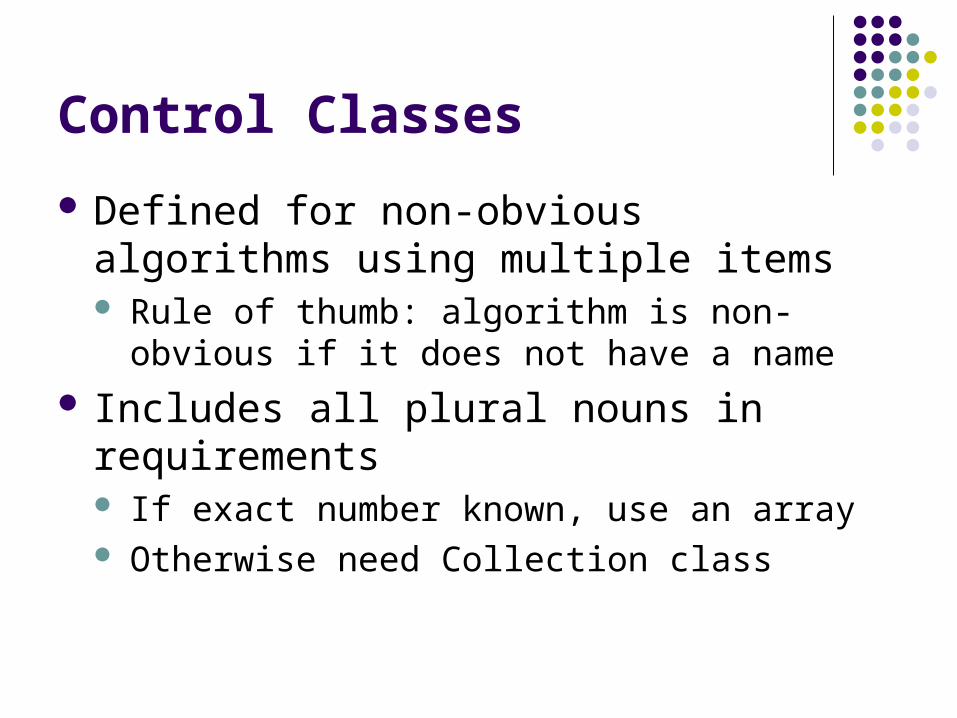
Defined for non-obvious algorithms using multiple items Rule of thumb: algorithm is non-obvious if it does
not have a name Includes all plural nouns in requirements
If exact number known, use an array Otherwise need Collection class
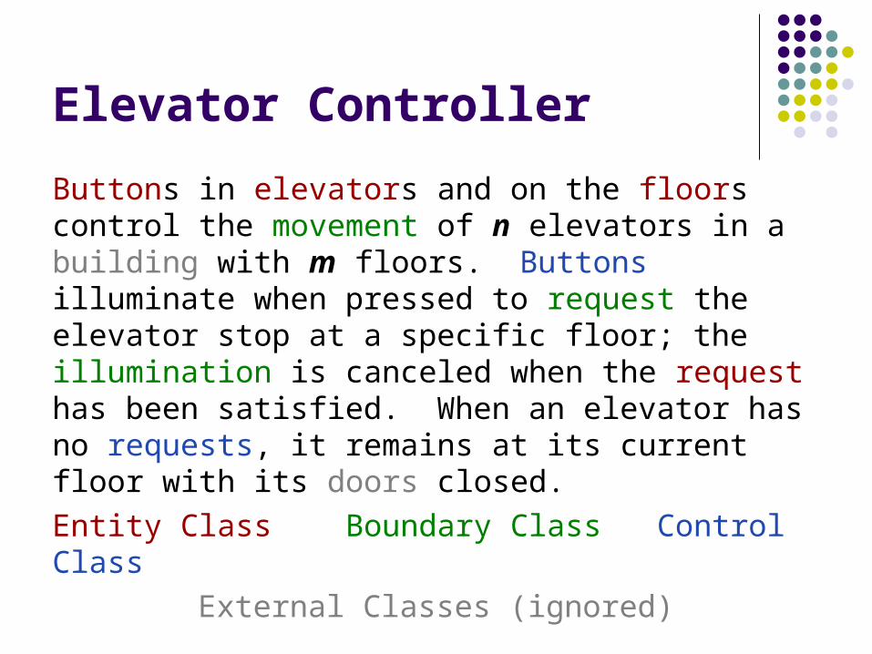
Buttons in elevators and on the floors control the movement of n elevators in a building with m floors. Buttons illuminate when pressed to request the elevator stop at a specific floor; the illumination is canceled when the request has been satisfied. When an elevator has no requests, it remains at its current floor with its doors closed.
Entity Class Boundary Class Control Class
External Classes (ignored)
Elevator Controller
UML Class Diagrams
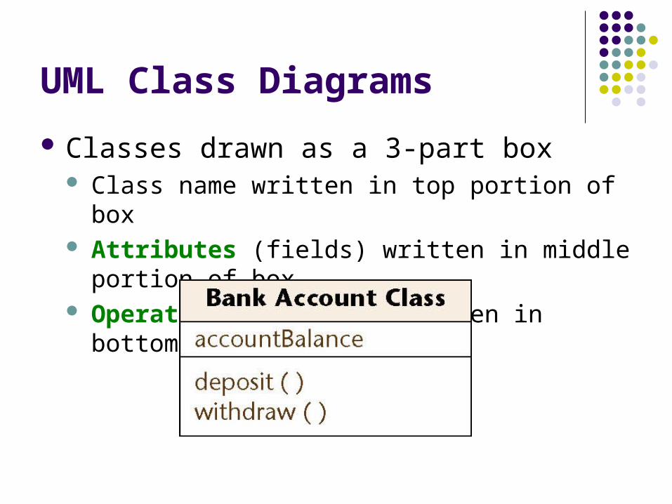
Classes drawn as a 3-part box Class name written in top portion of box Attributes (fields) written in middle portion of box Operations (methods) written in bottom portion
Connection Between Classes
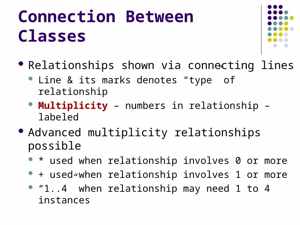
Relationships shown via connecting lines Line & its marks denotes “type” of relationship Multiplicity – numbers in relationship – labeled
Advanced multiplicity relationships possible * used when relationship involves 0 or more + used when relationship involves 1 or more “1..4” when relationship may need 1 to 4 instances
Connection Between Classes
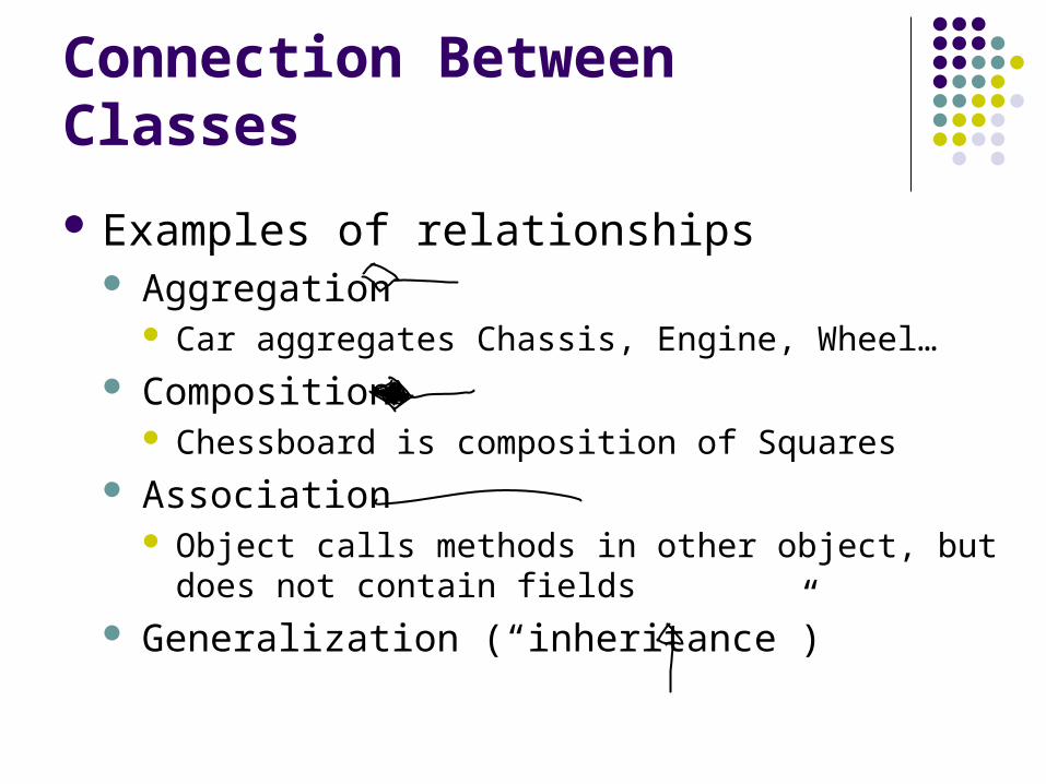
Examples of relationships Aggregation
Car aggregates Chassis, Engine, Wheel… Composition
Chessboard is composition of Squares Association
Object calls methods in other object, but does not contain fields
Generalization (“inheritance”)
UML Class Diagram for Elevator Controller
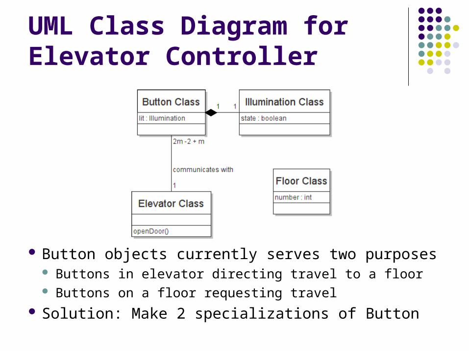
Button objects currently serves two purposes Buttons in elevator directing travel to a floor Buttons on a floor requesting travel
Solution: Make 2 specializations of Button
UML Class Diagram for Elevator Controller
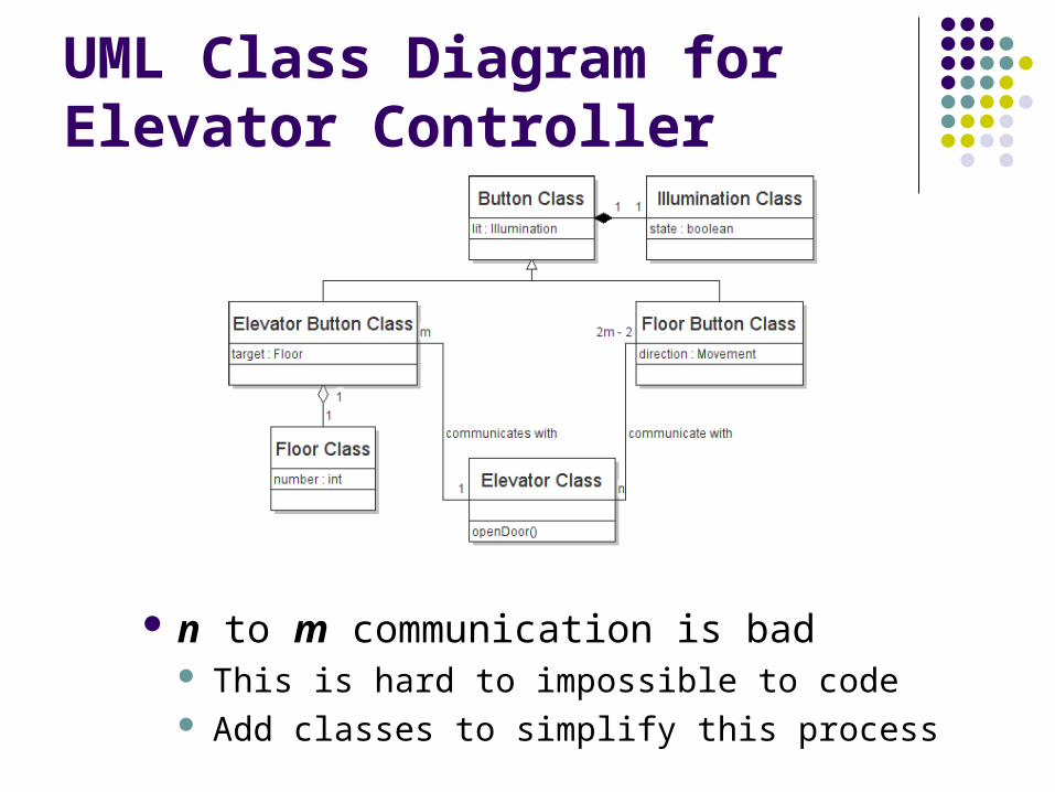
n to m communication is bad This is hard to impossible to code Add classes to simplify this process
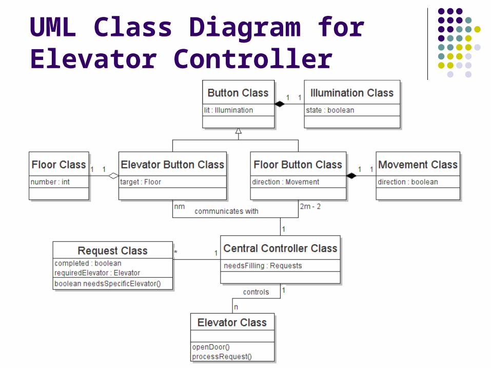
UML Class Diagram for Elevator Controller
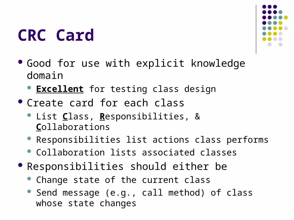
CRC Card
Good for use with explicit knowledge domain Excellent for testing class design
Create card for each class List Class, Responsibilities, & Collaborations Responsibilities list actions class performs Collaboration lists associated classes
Responsibilities should either be Change state of the current class Send message (e.g., call method) of class whose
state changes
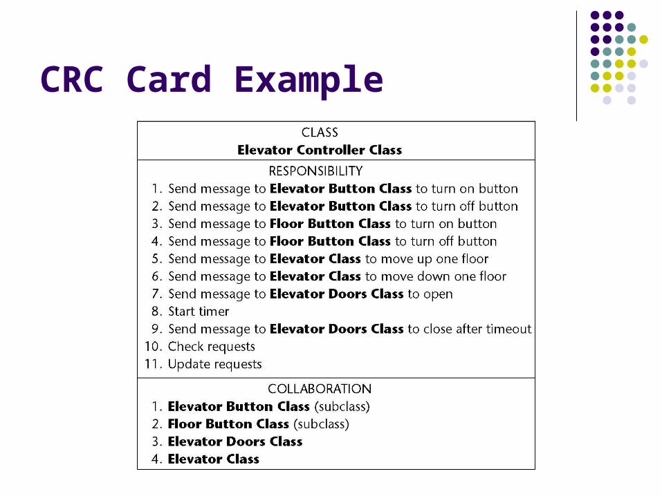
CRC Card Example
Dynamic Modeling
Dynamic modeling is 3rd step in extraction Constructs statechart showing software operation Operations determined from the scenarios
State diagrams (aka, event flow) rely on meaningful symbols Solid circle represents initial state White circle containing small black circle is final
state Other states use rectangles with rounded corners Arrows represent possible state transitions
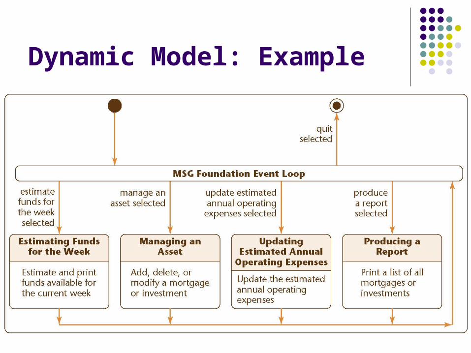
Dynamic Model: Example
For Next Lecture
Complete discussion OO analysis Developing sequence & collaboration diagrams to
refine use cases Give you chance to practice all these ideas