Embed Size (px)
Citation preview
CSA Z240.2.1 Technical Requirements for Manufactured Homes – Implications of the More Significant Proposed Changes
Prepared for the CSA Technical Committee
21 March 2014
Z240.2.1 Technical Requirements for Manufactured Homes 21 March 2014
Implications of the More Significant Proposed Changes Page i
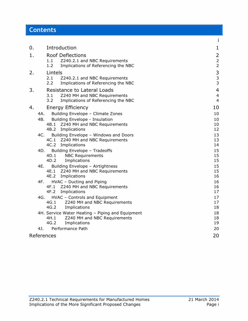
Contents
i
0. Introduction 1
1. Roof Deflections 2 1.1 Z240.2.1 and NBC Requirements 2 1.2 Implications of Referencing the NBC 2
2. Lintels 3 2.1 Z240.2.1 and NBC Requirements 3 2.2 Implications of Referencing the NBC 3
3. Resistance to Lateral Loads 4 3.1 Z240 MH and NBC Requirements 4 3.2 Implications of Referencing the NBC 4
4. Energy Efficiency 10
4A. Building Envelope – Climate Zones 10
4B. Building Envelope - Insulation 10 4B.1 Z240 MH and NBC Requirements 10 4B.2 Implications 12
4C. Building Envelope – Windows and Doors 13 4C.1 Z240 MH and NBC Requirements 13 4C.2 Implications 14
4D. Building Envelope – Tradeoffs 15 4D.1 NBC Requirements 15 4D.2 Implications 15
4E. Building Envelope – Airtightness 15 4E.1 Z240 MH and NBC Requirements 15 4E.2 Implications 16
4F. HVAC – Ducting and Piping 16 4F.1 Z240 MH and NBC Requirements 16 4F.2 Implications 17
4G. HVAC – Controls and Equipment 17 4G.1 Z240 MH and NBC Requirements 17 4G.2 Implications 18
4H. Service Water Heating – Piping and Equipment 18 4H.1 Z240 MH and NBC Requirements 18 4G.2 Implications 19
4J. Performance Path 20
References 20
Z240.2.1 Technical Requirements for Manufactured Homes 21 March 2014
Implications of More Significant Proposed Changes Page 1 of 20
0. Introduction
Proposed General Reference to the NBC
Many of the current requirements in Z240 MH Series are copies of requirements in the
National Building Code (NBC) or they reference NBC requirements. It is proposed that the
next edition of the standard reference the NBC as a general requirement and provide
explicit requirements and exceptions only where these are needed to address issues that
are specific to manufactured homes.
Implications – General
Where Z240 MH does not copy or reference NBC requirements, the resultant technical
changes may range from minimal to quite significant – sometimes making the requirement
less stringent and sometimes more stringent. This document provides information on the
proposed changes that could result in notably more stringent requirements.
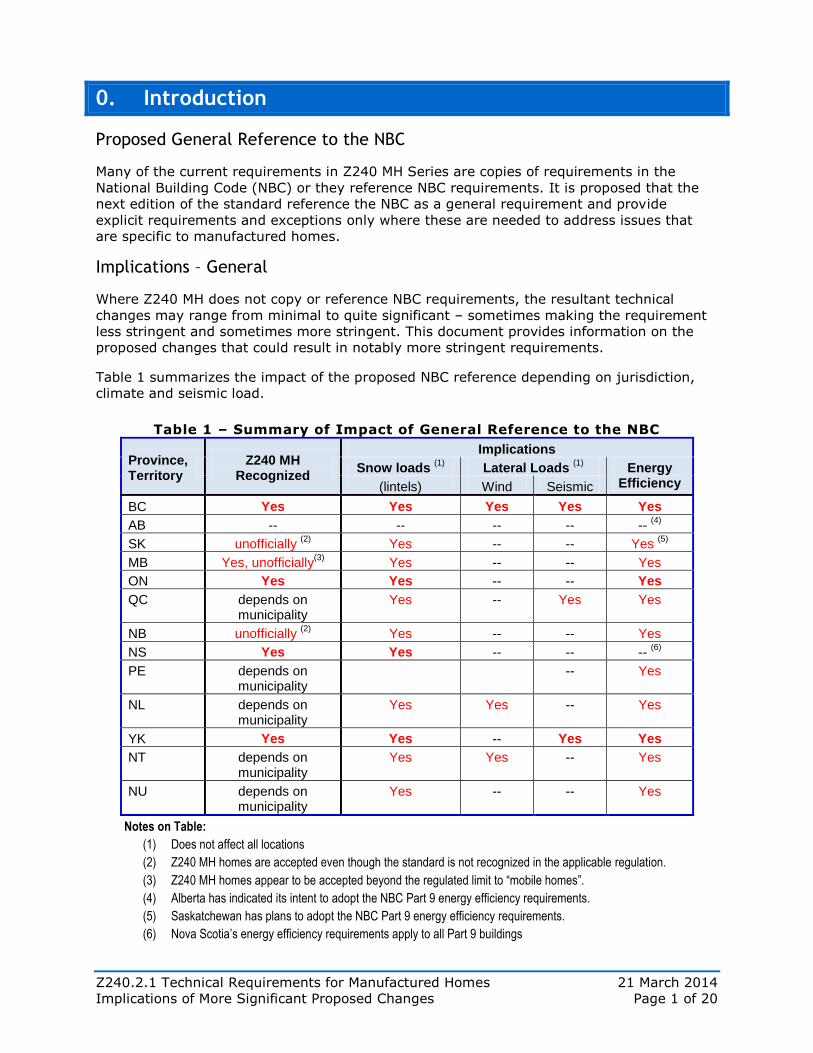
Table 1 summarizes the impact of the proposed NBC reference depending on jurisdiction,
climate and seismic load.
Table 1 – Summary of Impact of General Reference to the NBC
Province, Territory
Z240 MH Recognized
Implications
Snow loads (1)
Lateral Loads (1)
Energy Efficiency (lintels) Wind Seismic
BC Yes Yes Yes Yes Yes
AB -- -- -- -- -- (4)
SK unofficially (2)
Yes -- -- Yes (5)
MB Yes, unofficially(3)
Yes -- -- Yes
ON Yes Yes -- -- Yes
QC depends on municipality
Yes -- Yes Yes
NB unofficially (2)
Yes -- -- Yes
NS Yes Yes -- -- -- (6)
PE depends on municipality
-- Yes
NL depends on municipality
Yes Yes -- Yes
YK Yes Yes -- Yes Yes
NT depends on municipality
Yes Yes -- Yes
NU depends on municipality
Yes -- -- Yes
Notes on Table:
(1) Does not affect all locations
(2) Z240 MH homes are accepted even though the standard is not recognized in the applicable regulation.
(3) Z240 MH homes appear to be accepted beyond the regulated limit to “mobile homes”.
(4) Alberta has indicated its intent to adopt the NBC Part 9 energy efficiency requirements.
(5) Saskatchewan has plans to adopt the NBC Part 9 energy efficiency requirements.
(6) Nova Scotia’s energy efficiency requirements apply to all Part 9 buildings
Z240.2.1 Technical Requirements for Manufactured Homes 21 March 2014
Implications of More Significant Proposed Changes Page 2 of 20
1. Roof Deflections
1.1 Z240.2.1 and NBC Requirements
Limits and Test Criteria
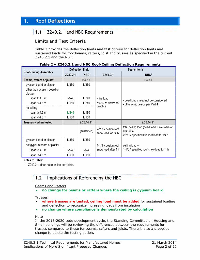
Table 2 provides the deflection limits and test criteria for deflection limits and
sustained loads for roof beams, rafters, joist and trusses as specified in the current
Z240.2.1 and the NBC.
Table 2 – Z240.2.1 and NBC Roof-Ceiling Deflection Requirements
Roof-Ceiling Assembly Deflection limit Test criteria
Z240.2.1 NBC Z240.2.1 NBC*
Beams, rafters or joists* 9.4.3.1. 9.4.3.1.
gypsum board or plaster L/360 L/360
- live load
- good engineering
practice
- dead loads need not be considered
- otherwise, design per Part 4
other than gypsum board or
plaster
span ≥ 4.3 m L//240 L/240
span < 4.3 m L/180 L/240
no ceiling
span ≥ 4.3 m L/240 L/180
span < 4.3 m L/180 L/180
Trusses – when tested 9.23.14.11. 9.23.14.11.
(sustained) 2-2/3 x design roof
snow load for 24 h
total ceiling load (dead load + live load) of
0.35 kPa +
2-2/3 x specified live roof load for 24 h
gypsum board or plaster L/360 L/360
1-1/3 x design roof
snow load after 1 h
ceiling load +
1-1/3 * specified roof snow load for 1 h
not gypsum board or plaster
span ≥ 4.3 m L//240 L//240
span < 4.3 m L/180 L/180
Notes to Table:
* Z240.2.1. does not mention roof joists.
1.2 Implications of Referencing the NBC
Beams and Rafters
no change for beams or rafters where the ceiling is gypsum board
Trusses
where trusses are tested, ceiling load must be added for sustained loading
and deflection to recognize increasing loads from insulation
no change where compliance is demonstrated by calculation
Note
In the 2015-2020 code development cycle, the Standing Committee on Housing and
Small buildings will be reviewing the differences between the requirements for
trusses compared to those for beams, rafters and joists. There is also a proposed
change to delete the testing option.
Z240.2.1 Technical Requirements for Manufactured Homes 21 March 2014
Implications of More Significant Proposed Changes Page 3 of 20
2. Lintels
2.1 Z240.2.1 and NBC Requirements
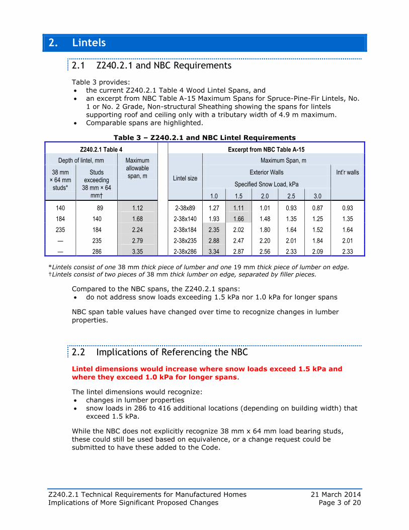
Table 3 provides:
the current Z240.2.1 Table 4 Wood Lintel Spans, and
an excerpt from NBC Table A-15 Maximum Spans for Spruce-Pine-Fir Lintels, No.
1 or No. 2 Grade, Non-structural Sheathing showing the spans for lintels
supporting roof and ceiling only with a tributary width of 4.9 m maximum.
Comparable spans are highlighted.
Table 3 – Z240.2.1 and NBC Lintel Requirements
Z240.2.1 Table 4 Excerpt from NBC Table A-15
Depth of lintel, mm Maximum allowable span, m
Lintel size
Maximum Span, m
38 mm × 64 mm
studs*
Studs exceeding
38 mm × 64 mm†
Exterior Walls Int’r walls
Specified Snow Load, kPa
1.0 1.5 2.0 2.5 3.0
140 89 1.12 2-38x89 1.27 1.11 1.01 0.93 0.87 0.93
184 140 1.68 2-38x140 1.93 1.66 1.48 1.35 1.25 1.35
235 184 2.24 2-38x184 2.35 2.02 1.80 1.64 1.52 1.64
— 235 2.79 2-38x235 2.88 2.47 2.20 2.01 1.84 2.01
— 286 3.35 2-38x286 3.34 2.87 2.56 2.33 2.09 2.33
*Lintels consist of one 38 mm thick piece of lumber and one 19 mm thick piece of lumber on edge. †Lintels consist of two pieces of 38 mm thick lumber on edge, separated by filler pieces.
Compared to the NBC spans, the Z240.2.1 spans:
do not address snow loads exceeding 1.5 kPa nor 1.0 kPa for longer spans
NBC span table values have changed over time to recognize changes in lumber
properties.
2.2 Implications of Referencing the NBC
Lintel dimensions would increase where snow loads exceed 1.5 kPa and
where they exceed 1.0 kPa for longer spans.
The lintel dimensions would recognize:
changes in lumber properties
snow loads in 286 to 416 additional locations (depending on building width) that
exceed 1.5 kPa.
While the NBC does not explicitly recognize 38 mm x 64 mm load bearing studs,
these could still be used based on equivalence, or a change request could be
submitted to have these added to the Code.
Z240.2.1 Technical Requirements for Manufactured Homes 21 March 2014
Implications of More Significant Proposed Changes Page 4 of 20
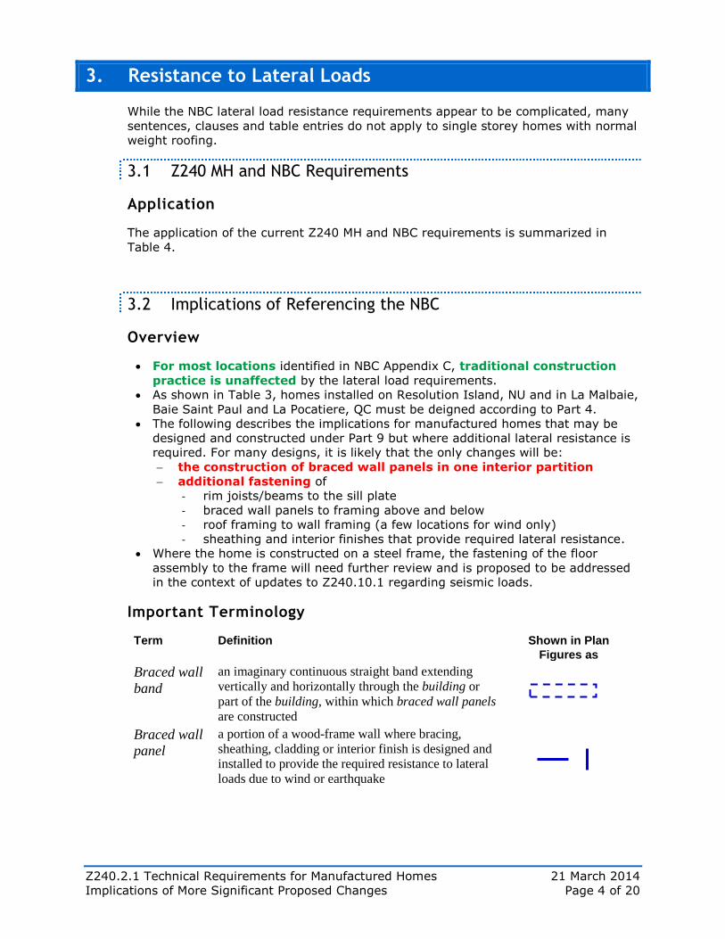
3. Resistance to Lateral Loads
While the NBC lateral load resistance requirements appear to be complicated, many
sentences, clauses and table entries do not apply to single storey homes with normal
weight roofing.
3.1 Z240 MH and NBC Requirements
Application
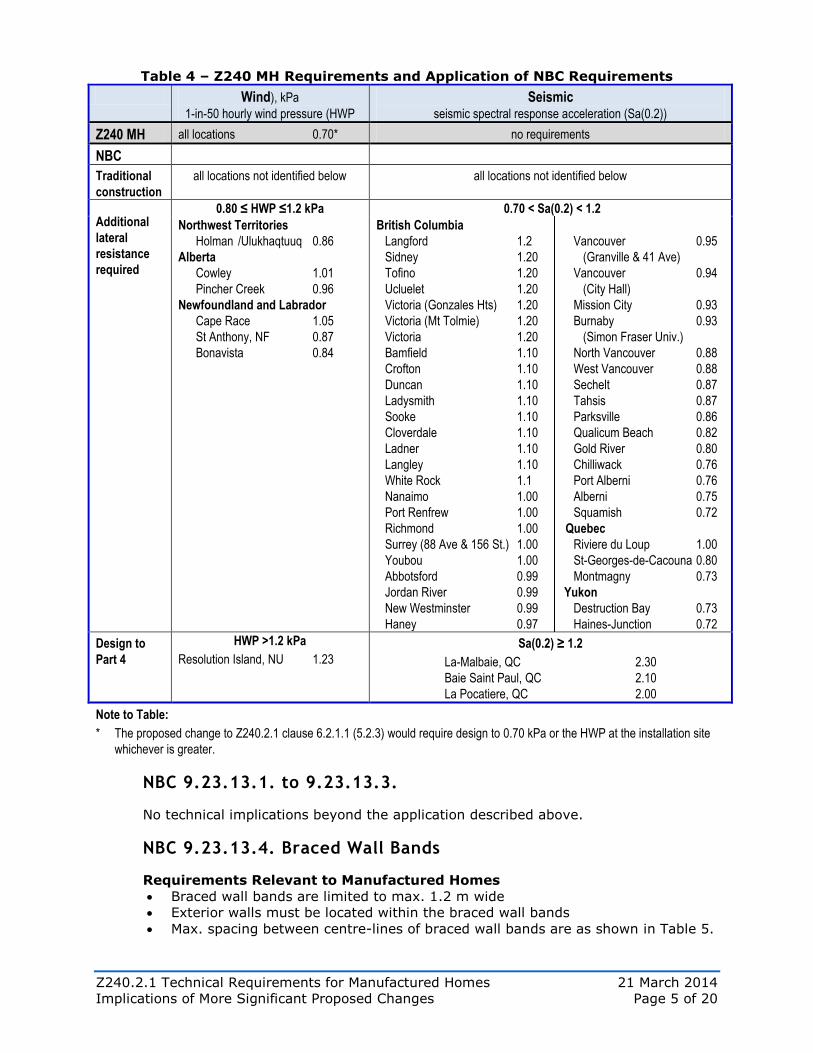
The application of the current Z240 MH and NBC requirements is summarized in
Table 4.
3.2 Implications of Referencing the NBC
Overview
For most locations identified in NBC Appendix C, traditional construction
practice is unaffected by the lateral load requirements.
As shown in Table 3, homes installed on Resolution Island, NU and in La Malbaie,
Baie Saint Paul and La Pocatiere, QC must be deigned according to Part 4.
The following describes the implications for manufactured homes that may be
designed and constructed under Part 9 but where additional lateral resistance is
required. For many designs, it is likely that the only changes will be:
the construction of braced wall panels in one interior partition
additional fastening of
- rim joists/beams to the sill plate
- braced wall panels to framing above and below
- roof framing to wall framing (a few locations for wind only)
- sheathing and interior finishes that provide required lateral resistance.
Where the home is constructed on a steel frame, the fastening of the floor
assembly to the frame will need further review and is proposed to be addressed
in the context of updates to Z240.10.1 regarding seismic loads.
Important Terminology
Term Definition Shown in Plan
Figures as
Braced wall
band
an imaginary continuous straight band extending
vertically and horizontally through the building or
part of the building, within which braced wall panels
are constructed
Braced wall
panel
a portion of a wood-frame wall where bracing,
sheathing, cladding or interior finish is designed and
installed to provide the required resistance to lateral
loads due to wind or earthquake
Z240.2.1 Technical Requirements for Manufactured Homes 21 March 2014
Implications of More Significant Proposed Changes Page 5 of 20
Table 4 – Z240 MH Requirements and Application of NBC Requirements
Wind), kPa
1-in-50 hourly wind pressure (HWP
Seismic
seismic spectral response acceleration (Sa(0.2))
Z240 MH all locations 0.70* no requirements
NBC
Traditional
construction
all locations not identified below all locations not identified below
Additional
lateral
resistance
required
0.80 ≤ HWP ≤1.2 kPa 0.70 < Sa(0.2) < 1.2
Northwest Territories
Holman /Ulukhaqtuuq 0.86
Alberta
Cowley 1.01
Pincher Creek 0.96
Newfoundland and Labrador
Cape Race 1.05
St Anthony, NF 0.87
Bonavista 0.84
British Columbia
Langford 1.2
Sidney 1.20
Tofino 1.20
Ucluelet 1.20
Victoria (Gonzales Hts) 1.20
Victoria (Mt Tolmie) 1.20
Victoria 1.20
Bamfield 1.10
Crofton 1.10
Duncan 1.10
Ladysmith 1.10
Sooke 1.10
Cloverdale 1.10
Ladner 1.10
Langley 1.10
White Rock 1.1
Nanaimo 1.00
Port Renfrew 1.00
Richmond 1.00
Surrey (88 Ave & 156 St.) 1.00
Youbou 1.00
Abbotsford 0.99
Jordan River 0.99
New Westminster 0.99
Haney 0.97
Vancouver 0.95
(Granville & 41 Ave)
Vancouver 0.94
(City Hall)
Mission City 0.93
Burnaby 0.93
(Simon Fraser Univ.)
North Vancouver 0.88
West Vancouver 0.88
Sechelt 0.87
Tahsis 0.87
Parksville 0.86
Qualicum Beach 0.82
Gold River 0.80
Chilliwack 0.76
Port Alberni 0.76
Alberni 0.75
Squamish 0.72
Quebec
Riviere du Loup 1.00
St-Georges-de-Cacouna 0.80
Montmagny 0.73
Yukon
Destruction Bay 0.73
Haines-Junction 0.72
Design to
Part 4
HWP >1.2 kPa
Resolution Island, NU 1.23
Sa(0.2) ≥ 1.2
La-Malbaie, QC 2.30
Baie Saint Paul, QC 2.10
La Pocatiere, QC 2.00
Note to Table:
* The proposed change to Z240.2.1 clause 6.2.1.1 (5.2.3) would require design to 0.70 kPa or the HWP at the installation site
whichever is greater.
NBC 9.23.13.1. to 9.23.13.3.
No technical implications beyond the application described above.
NBC 9.23.13.4. Braced Wall Bands
Requirements Relevant to Manufactured Homes
Braced wall bands are limited to max. 1.2 m wide
Exterior walls must be located within the braced wall bands
Max. spacing between centre-lines of braced wall bands are as shown in Table 5.
Z240.2.1 Technical Requirements for Manufactured Homes 21 March 2014
Implications of More Significant Proposed Changes Page 6 of 20
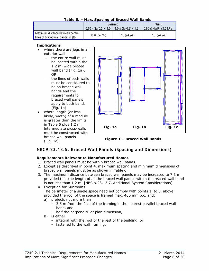
Table 5. – Max. Spacing of Braced Wall Bands
Seismic Wind
0.70 < Sa(0.2) < 1.0 1.0 ≤ Sa(0.2) < 1.2 0.80 ≤ HWP ≤1.2 kPa
Maximum distance between centre
lines of braced wall bands, m (ft) 10.6 (34.78’) 7.6 (24.94’) 7.6 (24.94’)
Implications
where there are jogs in an
exterior wall
the entire wall must
be located within the
1.2 m–wide braced
wall band (Fig. 1a),
OR
the lines of both walls
must be considered to
be on braced wall
bands and the
requirements for
braced wall panels
apply to both bands
(Fig. 1b)
where length (or less
likely, width) of a module
is greater than the limits
in Table 5 plus 1.2 m,
intermediate cross-walls
must be constructed with
braced wall panels
(Fig. 1c).
NBC9.23.13.5. Braced Wall Panels (Spacing and Dimensions)
Requirements Relevant to Manufactured Homes
1. Braced wall panels must be within braced wall bands.
2. Except as described in point 4, maximum spacing and minimum dimensions of
braced wall panels must be as shown in Table 6.
3. The maximum distance between braced wall panels may be increased to 7.3 m
provided that the length of all the braced wall panels within the braced wall band
is not less than 1.2 m. [NBC 9.23.13.7. Additional System Considerations]
4. Exception for Sunrooms
The perimeter of a single space need not comply with points 1. to 3. above
provided the roof of the space is framed max. 400 mm o.c. and:
a) projects not more than
- 3.5 m from the face of the framing in the nearest parallel braced wall
band, and
- half the perpendicular plan dimension,
b) is either
- integral with the roof of the rest of the building, or
- fastened to the wall framing.
Figure 1 – Braced Wall Bands
Fig. 1a Fig. 1b Fig. 1c
Z240.2.1 Technical Requirements for Manufactured Homes 21 March 2014
Implications of More Significant Proposed Changes Page 7 of 20
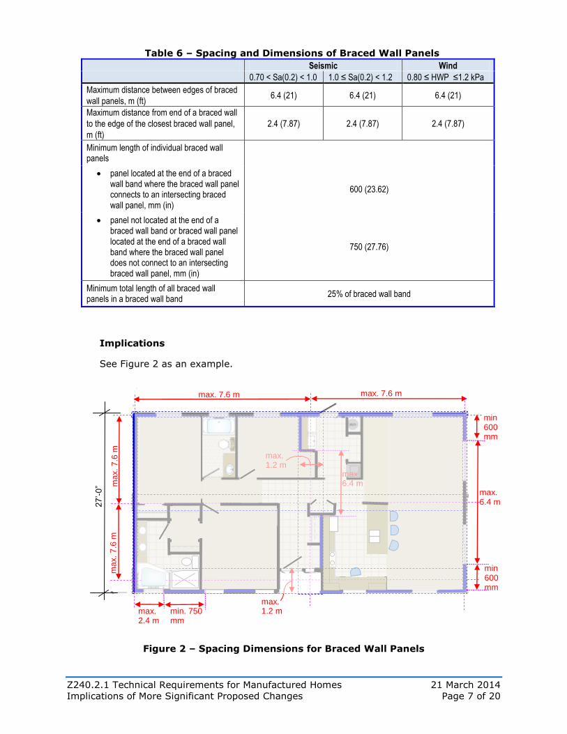
Table 6 – Spacing and Dimensions of Braced Wall Panels
Seismic Wind
0.70 < Sa(0.2) < 1.0 1.0 ≤ Sa(0.2) < 1.2 0.80 ≤ HWP ≤1.2 kPa
Maximum distance between edges of braced
wall panels, m (ft) 6.4 (21) 6.4 (21) 6.4 (21)
Maximum distance from end of a braced wall
to the edge of the closest braced wall panel,
m (ft)
2.4 (7.87) 2.4 (7.87) 2.4 (7.87)
Minimum length of individual braced wall panels
panel located at the end of a braced wall band where the braced wall panel connects to an intersecting braced wall panel, mm (in)
600 (23.62)
panel not located at the end of a braced wall band or braced wall panel located at the end of a braced wall band where the braced wall panel does not connect to an intersecting braced wall panel, mm (in)
750 (27.76)
Minimum total length of all braced wall panels in a braced wall band
25% of braced wall band
Implications
See Figure 2 as an example.
Figure 2 – Spacing Dimensions for Braced Wall Panels
27
’-0
”
max. 1.2 m
max. 7.6 m max. 7.6 m
ma
x. 7
.6 m
m
ax. 7
.6 m
max. 6.4 m
max. 1.2 m
max. 6.4 m
max. 2.4 m
min 600 mm
min. 750 mm
min 600 mm
Z240.2.1 Technical Requirements for Manufactured Homes 21 March 2014
Implications of More Significant Proposed Changes Page 8 of 20
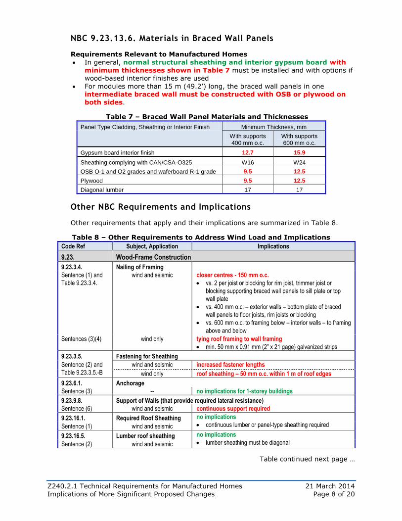
NBC 9.23.13.6. Materials in Braced Wall Panels
Requirements Relevant to Manufactured Homes
In general, normal structural sheathing and interior gypsum board with
minimum thicknesses shown in Table 7 must be installed and with options if
wood-based interior finishes are used
For modules more than 15 m (49.2’) long, the braced wall panels in one
intermediate braced wall must be constructed with OSB or plywood on
both sides.
Table 7 – Braced Wall Panel Materials and Thicknesses
Panel Type Cladding, Sheathing or Interior Finish Minimum Thickness, mm
With supports 400 mm o.c.
With supports 600 mm o.c.
Gypsum board interior finish 12.7 15.9
Sheathing complying with CAN/CSA-O325 W16 W24
OSB O-1 and O2 grades and waferboard R-1 grade 9.5 12.5
Plywood 9.5 12.5
Diagonal lumber 17 17
Other NBC Requirements and Implications
Other requirements that apply and their implications are summarized in Table 8.
Table 8 – Other Requirements to Address Wind Load and Implications
Code Ref Subject, Application Implications
9.23. Wood-Frame Construction
9.23.3.4. Nailing of Framing
Sentence (1) and
Table 9.23.3.4.
wind and seismic closer centres - 150 mm o.c.
vs. 2 per joist or blocking for rim joist, trimmer joist or
blocking supporting braced wall panels to sill plate or top
wall plate
vs. 400 mm o.c. – exterior walls – bottom plate of braced
wall panels to floor joists, rim joists or blocking
vs. 600 mm o.c. to framing below – interior walls – to framing
above and below
Sentences (3)(4) wind only tying roof framing to wall framing
min. 50 mm x 0.91 mm (2” x 21 gage) galvanized strips
9.23.3.5. Fastening for Sheathing
Sentence (2) and
Table 9.23.3.5.-B
wind and seismic increased fastener lengths
wind only roof sheathing – 50 mm o.c. within 1 m of roof edges
9.23.6.1. Anchorage
Sentence (3) -- no implications for 1-storey buildings
9.23.9.8. Support of Walls (that provide required lateral resistance)
Sentence (6) wind and seismic continuous support required
9.23.16.1. Required Roof Sheathing no implications
continuous lumber or panel-type sheathing required Sentence (1) wind and seismic
9.23.16.5. Lumber roof sheathing no implications
lumber sheathing must be diagonal Sentence (2) wind and seismic
Table continued next page …
Z240.2.1 Technical Requirements for Manufactured Homes 21 March 2014
Implications of More Significant Proposed Changes Page 9 of 20
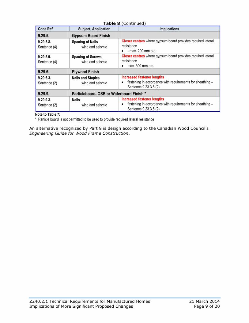
Table 8 (Continued)
Code Ref Subject, Application Implications
9.29.5. Gypsum Board Finish
9.29.5.8. Spacing of Nails Closer centres where gypsum board provides required lateral
resistance
- max. 200 mm o.c. Sentence (4) wind and seismic
9.29.5.9. Spacing of Screws Closer centres where gypsum board provides required lateral
resistance
max. 300 mm o.c. Sentence (4) wind and seismic
9.29.6. Plywood Finish
9.29.6.3. Nails and Staples increased fastener lengths
fastening in accordance with requirements for sheathing –
Sentence 9.23.3.5.(2) Sentence (2) wind and seismic
9.29.9. Particleboard, OSB or Waferboard Finish *
9.29.9.3. Nails increased fastener lengths
fastening in accordance with requirements for sheathing –
Sentence 9.23.3.5.(2) Sentence (2) wind and seismic
Note to Table 7:
* Particle board is not permitted to be used to provide required lateral resistance
An alternative recognized by Part 9 is design according to the Canadian Wood Council’s
Engineering Guide for Wood Frame Construction.
Z240.2.1 Technical Requirements for Manufactured Homes 21 March 2014
Implications of More Significant Proposed Changes Page 10 of 20
4. Energy Efficiency
4A. Building Envelope – Climate Zones
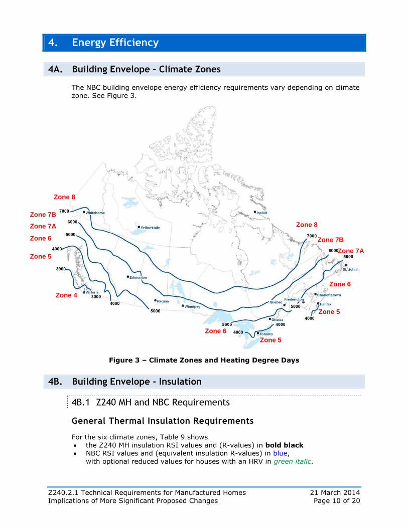
The NBC building envelope energy efficiency requirements vary depending on climate
zone. See Figure 3.
Figure 3 – Climate Zones and Heating Degree Days
4B. Building Envelope - Insulation
4B.1 Z240 MH and NBC Requirements
General Thermal Insulation Requirements
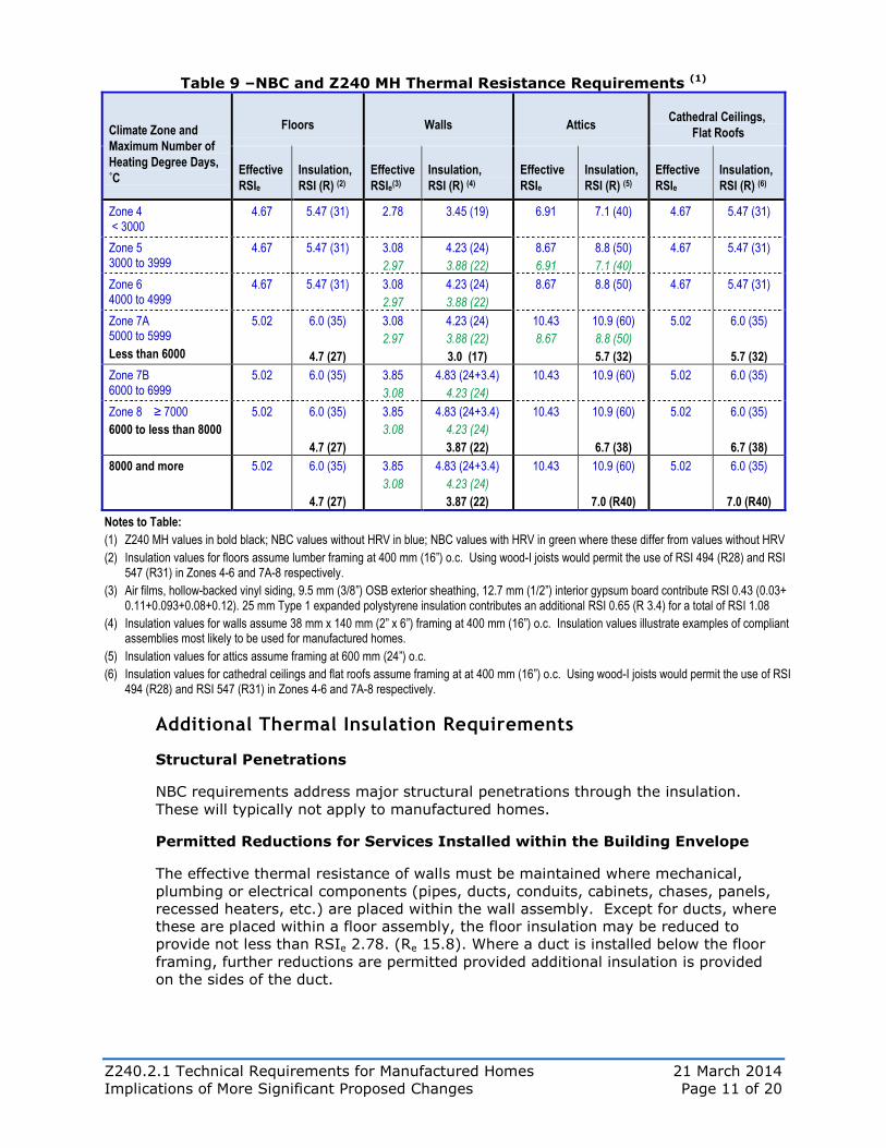
For the six climate zones, Table 9 shows
the Z240 MH insulation RSI values and (R-values) in bold black
NBC RSI values and (equivalent insulation R-values) in blue,
with optional reduced values for houses with an HRV in green italic.
Zone 8
Zone 7B
Zone 7A
Zone 7A
Zone 6
Zone 8
Zone 7B
Zone 6
Zone 5
Zone 5
Zone 4
Zone 6
Zone 5
Z240.2.1 Technical Requirements for Manufactured Homes 21 March 2014
Implications of More Significant Proposed Changes Page 11 of 20
Table 9 –NBC and Z240 MH Thermal Resistance Requirements (1)
Climate Zone and
Maximum Number of
Heating Degree Days,
˚C
Floors Walls Attics Cathedral Ceilings,
Flat Roofs
Effective
RSIe
Insulation,
RSI (R) (2)
Effective
RSIe(3)
Insulation,
RSI (R) (4)
Effective
RSIe
Insulation,
RSI (R) (5)
Effective
RSIe
Insulation,
RSI (R) (6)
Zone 4 < 3000
4.67 5.47 (31)
2.78 3.45 (19) 6.91 7.1 (40) 4.67 5.47 (31)
Zone 5 3000 to 3999
4.67 5.47 (31)
3.08
2.97
4.23 (24)
3.88 (22)
8.67
6.91
8.8 (50)
7.1 (40)
4.67 5.47 (31)
Zone 6 4000 to 4999
4.67 5.47 (31)
3.08
2.97
4.23 (24)
3.88 (22)
8.67 8.8 (50) 4.67 5.47 (31)
Zone 7A 5000 to 5999
Less than 6000
5.02 6.0 (35)
4.7 (27)
3.08
2.97
4.23 (24)
3.88 (22)
3.0 (17)
10.43
8.67
10.9 (60)
8.8 (50)
5.7 (32)
5.02 6.0 (35)
5.7 (32)
Zone 7B 6000 to 6999
5.02 6.0 (35) 3.85
3.08
4.83 (24+3.4)
4.23 (24)
10.43 10.9 (60) 5.02 6.0 (35)
Zone 8 ≥ 7000
6000 to less than 8000
5.02 6.0 (35)
4.7 (27)
3.85
3.08
4.83 (24+3.4)
4.23 (24)
3.87 (22)
10.43 10.9 (60)
6.7 (38)
5.02 6.0 (35)
6.7 (38)
8000 and more 5.02 6.0 (35)
4.7 (27)
3.85
3.08
4.83 (24+3.4)
4.23 (24)
3.87 (22)
10.43 10.9 (60)
7.0 (R40)
5.02 6.0 (35)
7.0 (R40)
Notes to Table:
(1) Z240 MH values in bold black; NBC values without HRV in blue; NBC values with HRV in green where these differ from values without HRV
(2) Insulation values for floors assume lumber framing at 400 mm (16”) o.c. Using wood-I joists would permit the use of RSI 494 (R28) and RSI 547 (R31) in Zones 4-6 and 7A-8 respectively.
(3) Air films, hollow-backed vinyl siding, 9.5 mm (3/8”) OSB exterior sheathing, 12.7 mm (1/2”) interior gypsum board contribute RSI 0.43 (0.03+ 0.11+0.093+0.08+0.12). 25 mm Type 1 expanded polystyrene insulation contributes an additional RSI 0.65 (R 3.4) for a total of RSI 1.08
(4) Insulation values for walls assume 38 mm x 140 mm (2” x 6”) framing at 400 mm (16”) o.c. Insulation values illustrate examples of compliant assemblies most likely to be used for manufactured homes.
(5) Insulation values for attics assume framing at 600 mm (24”) o.c.
(6) Insulation values for cathedral ceilings and flat roofs assume framing at at 400 mm (16”) o.c. Using wood-I joists would permit the use of RSI 494 (R28) and RSI 547 (R31) in Zones 4-6 and 7A-8 respectively.
Additional Thermal Insulation Requirements
Structural Penetrations
NBC requirements address major structural penetrations through the insulation.
These will typically not apply to manufactured homes.
Permitted Reductions for Services Installed within the Building Envelope
The effective thermal resistance of walls must be maintained where mechanical,
plumbing or electrical components (pipes, ducts, conduits, cabinets, chases, panels,
recessed heaters, etc.) are placed within the wall assembly. Except for ducts, where
these are placed within a floor assembly, the floor insulation may be reduced to
provide not less than RSIe 2.78. (Re 15.8). Where a duct is installed below the floor
framing, further reductions are permitted provided additional insulation is provided
on the sides of the duct.
Z240.2.1 Technical Requirements for Manufactured Homes 21 March 2014
Implications of More Significant Proposed Changes Page 12 of 20
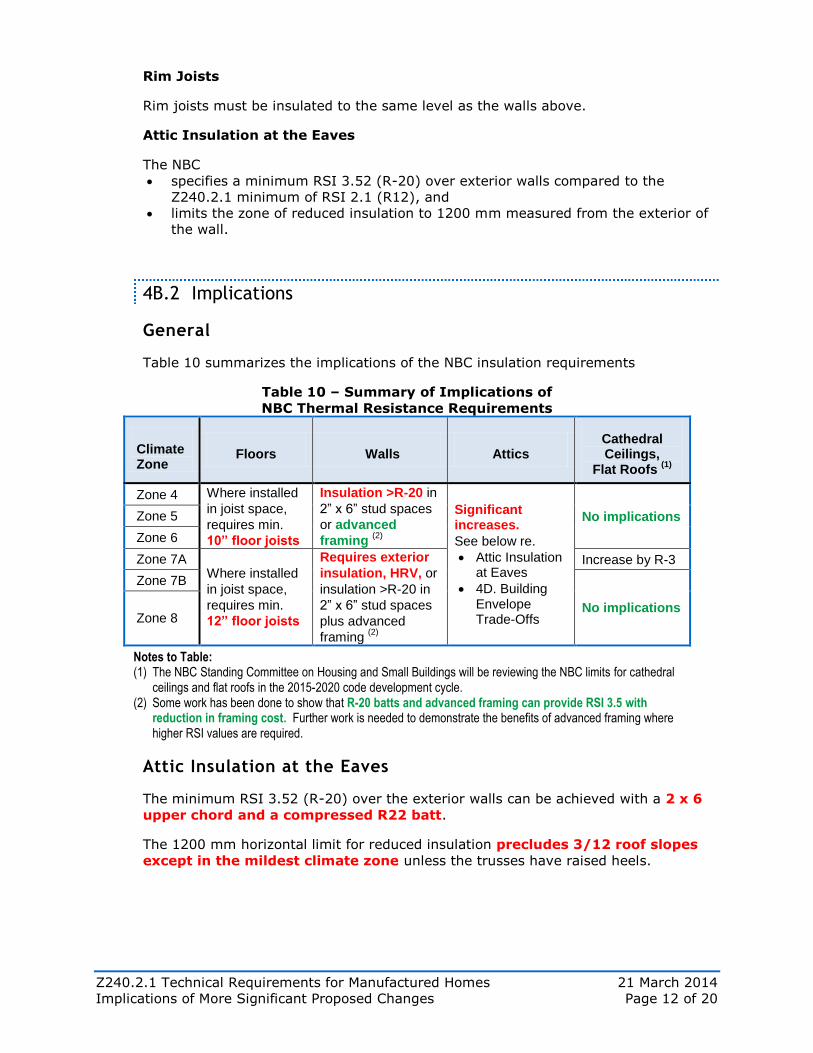
Rim Joists
Rim joists must be insulated to the same level as the walls above.
Attic Insulation at the Eaves
The NBC
specifies a minimum RSI 3.52 (R-20) over exterior walls compared to the
Z240.2.1 minimum of RSI 2.1 (R12), and
limits the zone of reduced insulation to 1200 mm measured from the exterior of
the wall.
4B.2 Implications
General
Table 10 summarizes the implications of the NBC insulation requirements
Table 10 – Summary of Implications of
NBC Thermal Resistance Requirements
Climate Zone
Floors Walls Attics Cathedral Ceilings,
Flat Roofs (1)
Zone 4 Where installed
in joist space,
requires min.
10” floor joists
Insulation >R-20 in
2” x 6” stud spaces
or advanced
framing (2)
Significant increases.
See below re.
Attic Insulation at Eaves
4D. Building Envelope Trade-Offs
No implications Zone 5
Zone 6
Zone 7A Where installed
in joist space,
requires min.
12” floor joists
Requires exterior
insulation, HRV, or
insulation >R-20 in
2” x 6” stud spaces
plus advanced
framing (2)
Increase by R-3
Zone 7B
No implications Zone 8
Notes to Table: (1) The NBC Standing Committee on Housing and Small Buildings will be reviewing the NBC limits for cathedral
ceilings and flat roofs in the 2015-2020 code development cycle. (2) Some work has been done to show that R-20 batts and advanced framing can provide RSI 3.5 with
reduction in framing cost. Further work is needed to demonstrate the benefits of advanced framing where higher RSI values are required.
Attic Insulation at the Eaves
The minimum RSI 3.52 (R-20) over the exterior walls can be achieved with a 2 x 6
upper chord and a compressed R22 batt.
The 1200 mm horizontal limit for reduced insulation precludes 3/12 roof slopes
except in the mildest climate zone unless the trusses have raised heels.
Z240.2.1 Technical Requirements for Manufactured Homes 21 March 2014
Implications of More Significant Proposed Changes Page 13 of 20
4C. Building Envelope – Windows and Doors
4C.1 Z240 MH and NBC Requirements
General
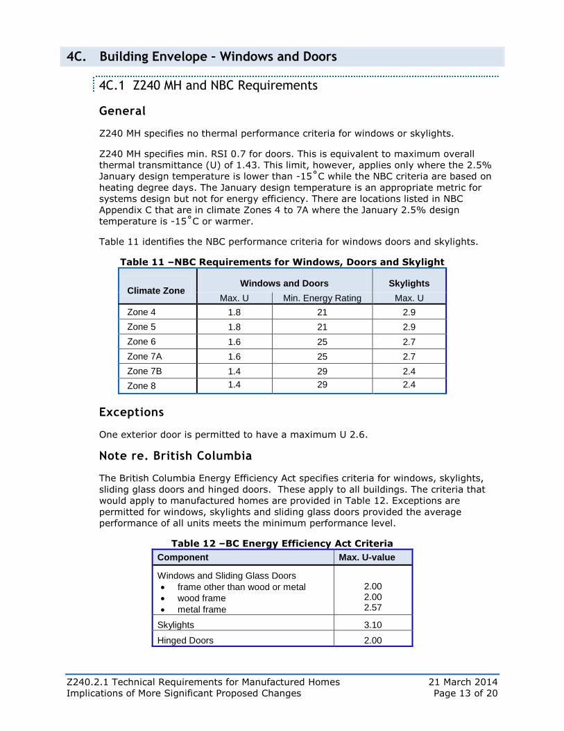
Z240 MH specifies no thermal performance criteria for windows or skylights.
Z240 MH specifies min. RSI 0.7 for doors. This is equivalent to maximum overall
thermal transmittance (U) of 1.43. This limit, however, applies only where the 2.5%
January design temperature is lower than -15˚C while the NBC criteria are based on
heating degree days. The January design temperature is an appropriate metric for
systems design but not for energy efficiency. There are locations listed in NBC
Appendix C that are in climate Zones 4 to 7A where the January 2.5% design
temperature is -15˚C or warmer.
Table 11 identifies the NBC performance criteria for windows doors and skylights.
Table 11 –NBC Requirements for Windows, Doors and Skylight
Climate Zone Windows and Doors Skylights
Max. U Min. Energy Rating Max. U
Zone 4 1.8 21 2.9
Zone 5 1.8 21 2.9
Zone 6 1.6 25 2.7
Zone 7A 1.6 25 2.7
Zone 7B 1.4 29 2.4
Zone 8 1.4 29 2.4
Exceptions
One exterior door is permitted to have a maximum U 2.6.
Note re. British Columbia
The British Columbia Energy Efficiency Act specifies criteria for windows, skylights,
sliding glass doors and hinged doors. These apply to all buildings. The criteria that
would apply to manufactured homes are provided in Table 12. Exceptions are
permitted for windows, skylights and sliding glass doors provided the average
performance of all units meets the minimum performance level.
Table 12 –BC Energy Efficiency Act Criteria
Component Max. U-value
Windows and Sliding Glass Doors
frame other than wood or metal
wood frame
metal frame
2.00 2.00 2.57
Skylights 3.10
Hinged Doors 2.00
Z240.2.1 Technical Requirements for Manufactured Homes 21 March 2014
Implications of More Significant Proposed Changes Page 14 of 20
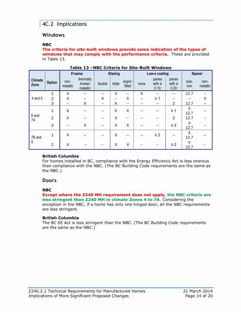
4C.2 Implications
Windows
NBC
The criteria for site-built windows provide some indication of the types of
windows that may comply with the performance criteria. These are provided
in Table 13.
Table 13 –NBC Criteria for Site-Built Windows
Climate Zone
Option
Frame Glazing Low-e coating Spacer
non-metallic
thermally broken metallic
double triple argon-filled
none panes with ≤ 0.10
panes with ≤ 0.20
size, mm
non-metallic
4 and 5 1 X -- -- X -- X -- -- 12.7 --
2 X -- X -- X -- ≥ 1 -- -- X
3 -- X -- X -- -- -- 2 12.7 --
6 and 7A
1 X -- -- X X -- -- ≥ 1 ≥
12.7 --
2 X -- -- X -- -- -- 2 12.7 --
3 -- X -- X X -- -- ≥ 2 ≥
12.7 --
7B and 8
1 X -- -- X -- -- ≥ 2 -- ≥
12.7 --
2 X -- -- X X -- -- ≥ 2 ≥
12.7 --
British Columbia
For homes installed in BC, compliance with the Energy Efficiency Act is less onerous
than compliance with the NBC. (The BC Building Code requirements are the same as
the NBC.)
Doors
NBC
Except where the Z240 MH requirement does not apply, the NBC criteria are
less stringent than Z240 MH in climate Zones 4 to 7A. Considering the
exception in the NBC, if a home has only one hinged door, all the NBC requirements
are less stringent.
British Columbia
The BC EE Act is less stringent than the NBC. (The BC Building Code requirements
are the same as the NBC.)
Z240.2.1 Technical Requirements for Manufactured Homes 21 March 2014
Implications of More Significant Proposed Changes Page 15 of 20
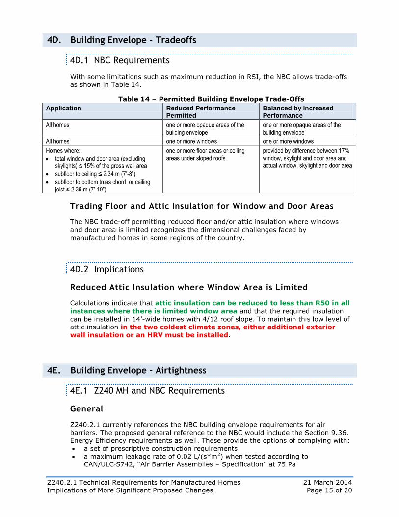
4D. Building Envelope – Tradeoffs
4D.1 NBC Requirements
With some limitations such as maximum reduction in RSI, the NBC allows trade-offs
as shown in Table 14.
Table 14 – Permitted Building Envelope Trade-Offs
Application Reduced Performance Permitted
Balanced by Increased Performance
All homes one or more opaque areas of the building envelope
one or more opaque areas of the building envelope
All homes one or more windows one or more windows
Homes where:
total window and door area (excluding skylights) ≤ 15% of the gross wall area
subfloor to ceiling ≤ 2.34 m (7’-8”)
subfloor to bottom truss chord or ceiling joist ≤ 2.39 m (7’-10”)
one or more floor areas or ceiling areas under sloped roofs
provided by difference between 17% window, skylight and door area and actual window, skylight and door area
Trading Floor and Attic Insulation for Window and Door Areas
The NBC trade-off permitting reduced floor and/or attic insulation where windows
and door area is limited recognizes the dimensional challenges faced by
manufactured homes in some regions of the country.
4D.2 Implications
Reduced Attic Insulation where Window Area is Limited
Calculations indicate that attic insulation can be reduced to less than R50 in all
instances where there is limited window area and that the required insulation
can be installed in 14’-wide homes with 4/12 roof slope. To maintain this low level of
attic insulation in the two coldest climate zones, either additional exterior
wall insulation or an HRV must be installed.
4E. Building Envelope – Airtightness
4E.1 Z240 MH and NBC Requirements
General
Z240.2.1 currently references the NBC building envelope requirements for air
barriers. The proposed general reference to the NBC would include the Section 9.36.
Energy Efficiency requirements as well. These provide the options of complying with:
a set of prescriptive construction requirements
a maximum leakage rate of 0.02 L/(s*m2) when tested according to
CAN/ULC‐S742, “Air Barrier Assemblies – Specification” at 75 Pa
Z240.2.1 Technical Requirements for Manufactured Homes 21 March 2014
Implications of More Significant Proposed Changes Page 16 of 20
OR
a maximum leakage rate of 0.02 L/(s*m2) when tested according to ASTM E
2357, “Determining Air Leakage of Air Barrier Assemblies” where the building will
not be subjected to 1/50 sustained wind loads exceeding 0.65 kPa. (This
standard could be used for all but 27 locations listed in NBC Appendix C.)
Specific
The NBC energy efficiency requirements for air barriers specify:
air barrier material compliance with CAN/ULC‐S741, “Air Barrier Materials –
Specification”
sealant material compliance with one of a number of standards
specific constructions for various penetrations, joints and junctions.
4E.2 Implications
Compliance with Test
Standard factory-construction practices should be such that manufactured homes
should comply with the performance limit of 0.02 L/(s*m2) when tested at 75 Pa.
Compliance with prescriptive Requirements
The prescriptive construction requirements essentially describe accepted good
practice. Standard factory-construction practices should be such that manufactured
homes should comply.
4F. HVAC – Ducting and Piping
4F.1 Z240 MH and NBC Requirements
Duct Sealing and Insulation
The application of the NBC duct sealing requirement is not as broad as in Z240 MH.
The NBC, however, does not permit the use of fabric‐backed tape with rubber
adhesives to provide the required airtightness.
Z240 MH requires exposed ducts to be insulated to a minimum of RSI 1.23 (R-7).
The NBC requires, in general, that ducts be insulated to the same level as walls. An
exception allows a minimum RSI 2.11 (R-12) under ducts installed under an
insulated floor provided additional insulation is installed on the sides so that there is
no increase in the total heat loss. An Appendix table provides a number of deemed-
to-comply solutions for various climate zones and duct dimensions.
Pipe Insulation
The NBC requires that piping installed outside the building envelope, except
high‐temperature refrigerant piping, be insulated to the same level as walls.
Z240 MH has no requirement.
Z240.2.1 Technical Requirements for Manufactured Homes 21 March 2014
Implications of More Significant Proposed Changes Page 17 of 20
Dampers
The NBC requires all duct openings to be equipped with a damper except:
where dampers are not permitted by other regulations
on air intakes in locations with fewer than 3500 heating degree days (climate
Zone 4 and some locations in climate Zone 5).
4F.2 Implications
Duct Sealing and Insulation
Sealing
Manufactured homes should comply with the NBC requirement provided fabric-
backed tape with rubber adhesive is not used.
Insulation
Depending on the proximity of ducting to the eaves, manufactured homes should be
able to meet the insulation requirement for ducts installed in attics.
For single-section homes where transportation height limits are stringent, the
insulation of ducts installed under the floor framing is more of a challenge. With
additional insulation on the sides of the duct, RSI 2.11 can be used in Zone 4, and in
Zones 5 to 7A provided an HRV is installed. Otherwise, additional thickness must
be provided or the insulation material must be more effective. The latter
should become a practical option with the expected approval of an NBC proposed
change to permit foam plastic insulation for ducts (some limitations apply).
Dampers
Except in climate Zone 4 and some locations in climate Zone 5, depending on current
practice there may be an additional cost for dampers.
4G. HVAC – Controls and Equipment
4G.1 Z240 MH and NBC Requirements
Controls
The NBC requirements specify various types of controls that must be installed and
required characteristics of those controls.
Equipment
The NBC specifies required performance levels for HVAC equipment. Equipment
efficiencies are the same or somewhat more stringent than the energy efficiency
ratings specified by the national Energy Efficiency Act. Table 15 provides a few
examples for heating equipment.
Z240.2.1 Technical Requirements for Manufactured Homes 21 March 2014
Implications of More Significant Proposed Changes Page 18 of 20
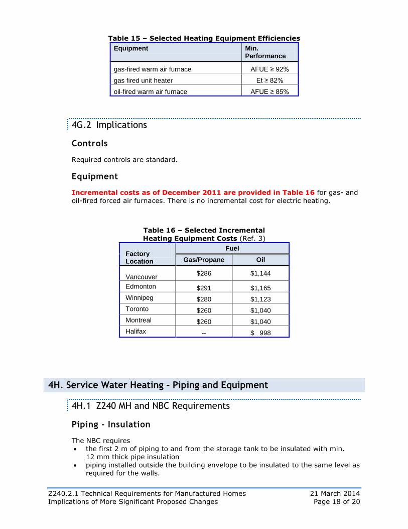
Table 15 – Selected Heating Equipment Efficiencies
Equipment Min. Performance
gas-fired warm air furnace AFUE ≥ 92%
gas fired unit heater Et ≥ 82%
oil-fired warm air furnace AFUE ≥ 85%
4G.2 Implications
Controls
Required controls are standard.
Equipment
Incremental costs as of December 2011 are provided in Table 16 for gas- and
oil-fired forced air furnaces. There is no incremental cost for electric heating.
Table 16 – Selected Incremental
Heating Equipment Costs (Ref. 3)
Factory Location
Fuel
Gas/Propane Oil
Vancouver $286 $1,144
Edmonton $291 $1,165
Winnipeg $280 $1,123
Toronto $260 $1,040
Montreal $260 $1,040
Halifax -- $ 998
4H. Service Water Heating – Piping and Equipment
4H.1 Z240 MH and NBC Requirements
Piping - Insulation
The NBC requires
the first 2 m of piping to and from the storage tank to be insulated with min.
12 mm thick pipe insulation
piping installed outside the building envelope to be insulated to the same level as
required for the walls.
Z240.2.1 Technical Requirements for Manufactured Homes 21 March 2014
Implications of More Significant Proposed Changes Page 19 of 20
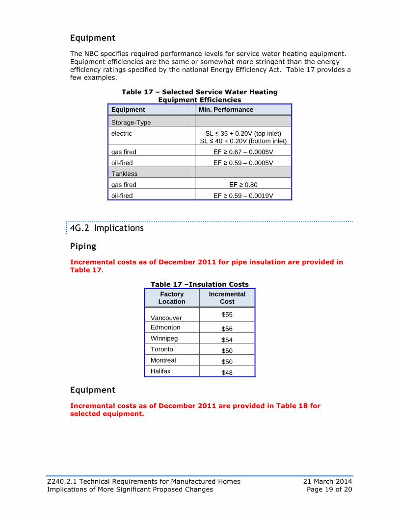
Equipment
The NBC specifies required performance levels for service water heating equipment.
Equipment efficiencies are the same or somewhat more stringent than the energy
efficiency ratings specified by the national Energy Efficiency Act. Table 17 provides a
few examples.
Table 17 – Selected Service Water Heating
Equipment Efficiencies
Equipment Min. Performance
Storage-Type
electric SL ≤ 35 + 0.20V (top inlet) SL ≤ 40 + 0.20V (bottom inlet)
gas fired EF ≥ 0.67 – 0.0005V
oil-fired EF ≥ 0.59 – 0.0005V
Tankless
gas fired EF ≥ 0.80
oil-fired EF ≥ 0.59 – 0.0019V
4G.2 Implications
Piping
Incremental costs as of December 2011 for pipe insulation are provided in
Table 17.
Table 17 –Insulation Costs
Factory Location
Incremental Cost
Vancouver $55
Edmonton $56
Winnipeg $54
Toronto $50
Montreal $50
Halifax $48
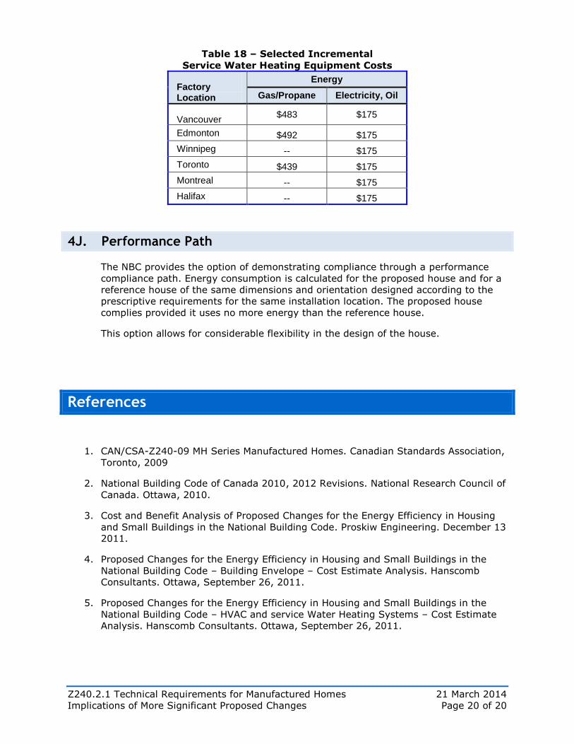
Equipment
Incremental costs as of December 2011 are provided in Table 18 for
selected equipment.
Z240.2.1 Technical Requirements for Manufactured Homes 21 March 2014
Implications of More Significant Proposed Changes Page 20 of 20
Table 18 – Selected Incremental
Service Water Heating Equipment Costs
Factory Location
Energy
Gas/Propane Electricity, Oil
Vancouver $483 $175
Edmonton $492 $175
Winnipeg -- $175
Toronto $439 $175
Montreal -- $175
Halifax -- $175
4J. Performance Path
The NBC provides the option of demonstrating compliance through a performance
compliance path. Energy consumption is calculated for the proposed house and for a
reference house of the same dimensions and orientation designed according to the
prescriptive requirements for the same installation location. The proposed house
complies provided it uses no more energy than the reference house.
This option allows for considerable flexibility in the design of the house.
References
1. CAN/CSA-Z240-09 MH Series Manufactured Homes. Canadian Standards Association,
Toronto, 2009
2. National Building Code of Canada 2010, 2012 Revisions. National Research Council of
Canada. Ottawa, 2010.
3. Cost and Benefit Analysis of Proposed Changes for the Energy Efficiency in Housing
and Small Buildings in the National Building Code. Proskiw Engineering. December 13
2011.
4. Proposed Changes for the Energy Efficiency in Housing and Small Buildings in the
National Building Code – Building Envelope – Cost Estimate Analysis. Hanscomb
Consultants. Ottawa, September 26, 2011.
5. Proposed Changes for the Energy Efficiency in Housing and Small Buildings in the
National Building Code – HVAC and service Water Heating Systems – Cost Estimate
Analysis. Hanscomb Consultants. Ottawa, September 26, 2011.