Embed Size (px)
Citation preview

CS48704-1/47
Illinois Institute of Technology
CS487
Software Engineering
Requirements II- part B
Instructor David Lash
CS48704-2/47
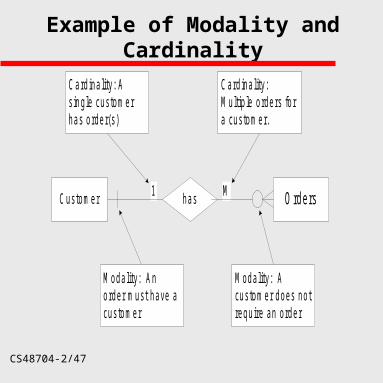
Example of Modality and Cardinality
Customer has Orders
M odality: Anorder must have acustomer
M odality: Acustomer does notrequire an order
Card ina lity: Asing le customerhas order(s)
Card ina lity:M ultip le orders fora customer.
1 M
CS48704-3/47
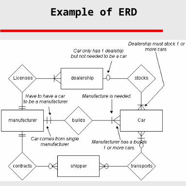
Example of ERD
CS48704-4/47
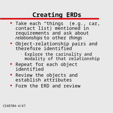
Creating ERDs Take each “things” (e.g., car, contact list)
mentioned in requirements and ask about relationships to other things
Object-relationship pairs and therefore identified
– Explore the carinality and modality of that relationship
Repeat for each object identified Review the objects and establish
attributes Form the ERD and review
CS48704-5/47
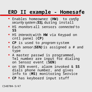
ERD II example - Homesafe Enables homeowner (HW) to config
security system (SS), during install HS monitors all sensors connected to SS HS interacts with HW via Keypad on cntl
panel (CP) CP is used to program system Each sensor (SEN) is assigned a # and
type A master passwd is programmed, Tel
number are input for dialing on Sensor event (SEN)
on SEN event, alarm invoked & SS dials phone number, and gives info to (MS) monitoring Service
CP has keyboard input stuff
CS48704-6/47
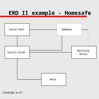
ERD II example - Homesafe
Sensor
Security System
HomeOwner
MonitoringService
Control Panel
CS48704-7/47
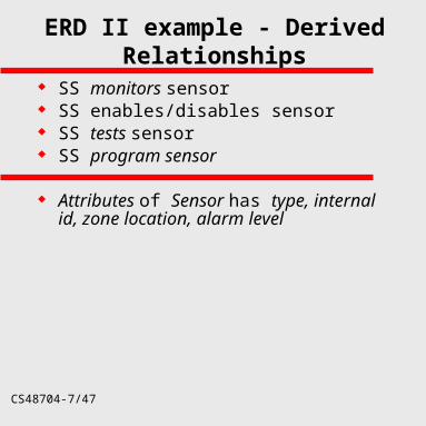
ERD II example - Derived Relationships
SS monitors sensor SS enables/disables sensor SS tests sensor SS program sensor
Attributes of Sensor has type, internal id, zone location, alarm level
CS48704-8/47
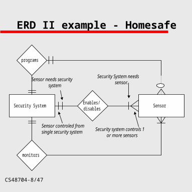
ERD II example - Homesafe
programs
Enables/disables
monitors
SensorSecurity System
Security system controls 1or more sensors
Security System needssensor.
Sensor controled fromsingle security system
Sensor needs securitysystem
CS48704-9/47
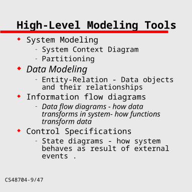
High-Level Modeling Tools System Modeling
– System Context Diagram– Partitioning
Data Modeling – Entity-Relation - Data objects and their
relationships Information flow diagrams
– Data flow diagrams - how data transforms in system- how functions transform data
Control Specifications– State diagrams - how system behaves
as result of external events .
CS48704-10/47
Data Flow Diagrams ( Information Flow )
A graphical technique that depicts information flow and the transforms that are applied as data moves from input to output.
– Input can be sensor, human operator, web page input, hardware
– Transformation can be logical comparison, numerical algorithm, graphic algorithm,
– Output can be LED, web page, report, effect on hardware
CS48704-11/47
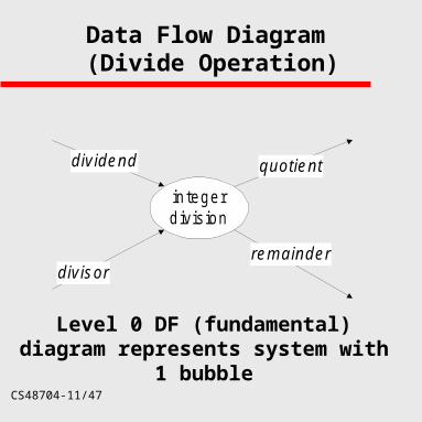
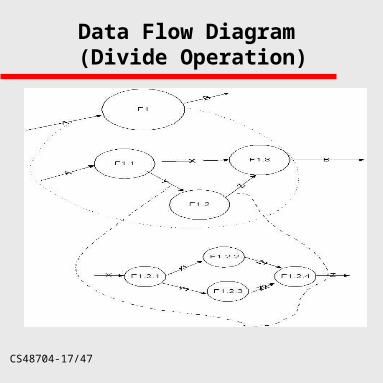
Data Flow Diagram (Divide Operation)
in tege rd iv is ion
d iv idend
d iv iso rrem a inde r
quo tien t
Level 0 DF (fundamental) diagram represents system with 1 bubble
CS48704-12/47
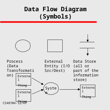
Data Flow Diagram(Symbols)
Process (Data Transformation)
External Entity (I/O Src/Dest)
Data Store (all or part of the information store)
System
External
Thing
External
Thing
External
Thing
CS48704-13/47
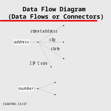
Data Flow Diagram (Data Flows or Connectors)
address
s tree t add ress
c ity
s ta te
Z IP C ode
num ber
CS48704-14/47
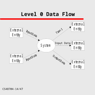
Level 0 Data Flow
E xte rna lE n tity
E xte rna lE n tity
S ys tem
E xte rna lE n tity
E xte rna lE n tity
E xte rna lE n tity
Output dataInput Data
CS48704-15/47
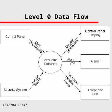
Level 0 Data Flow

CS48704-16/47
Level 0 Data Flow (Interactive System)
E xte rna lE n tity
S ys tem
M anua lInpu t
G enera tedO utpu t
A generalization of users
CS48704-17/47
Data Flow Diagram (Divide Operation)
CS48704-18/47
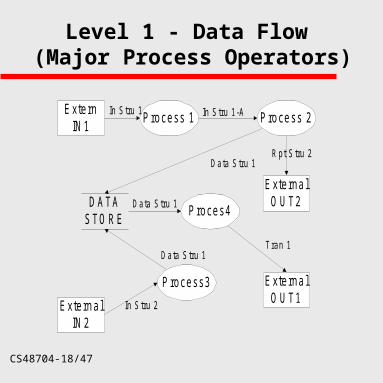
Level 1 - Data Flow (Major Process Operators)
E xte rnIN 1
E xte rna lIN 2
P rocess3
P rocess 1
D A TAS TO R E
P rocess 2
E xte rna lO U T1
P roces4
In Stru 1 In Stru 1-A
Data Stru 1
Data Stru 1
Data Stru 1
E xte rna lO U T2
In Stru 2
Rpt Stru 2
Tran 1
CS48704-19/47
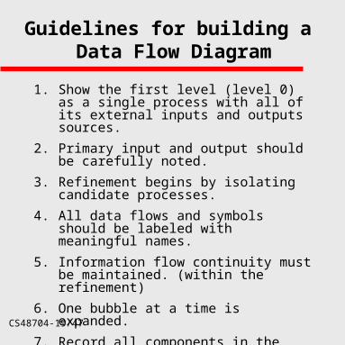
Guidelines for building a Data Flow Diagram
1. Show the first level (level 0) as a single process with all of its external inputs and outputs sources.
2. Primary input and output should be carefully noted.
3. Refinement begins by isolating candidate processes.
4. All data flows and symbols should be labeled with meaningful names.
5. Information flow continuity must be maintained. (within the refinement)
6. One bubble at a time is expanded.
7. Record all components in the data dictionary.
CS48704-20/47
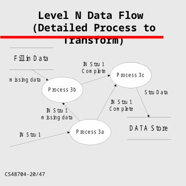
Level N Data Flow (Detailed Process to Transform)
Process 3a
Process 3b
Process 3c
D A TA S to reIN Stru 1
IN Stru 1Com plete
IN Stru 1Com plete
Stru Data
IN Stru 1m issing data
F ill in D a ta
m issing data
CS48704-21/47
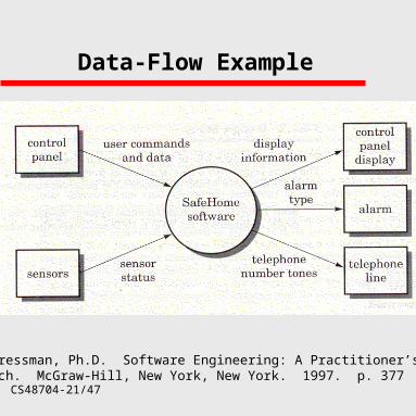
Data-Flow Example
R.S. Pressman, Ph.D. Software Engineering: A Practitioner’s Approach. McGraw-Hill, New York, New York. 1997. p. 377
CS48704-22/47
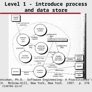
Level 1 - introduce process and data store
R.S. Pressman, Ph.D. Software Engineering: A Practitioner’s Approach. McGraw-Hill, New York, New York. 1997. p. 378
CS48704-23/47
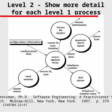
Level 2 - Show more detail for each level 1 process (monitor sensors)
R.S. Pressman, Ph.D. Software Engineering: A Practitioner’s Approach. McGraw-Hill, New York, New York. 1997. p. 379
CS48704-24/47
Behavioral Modeling
Behavior is the observable effects of an event,
including its results.
Control flow diagramming – An extension to data flow diagramming
– Adds events to the data model
State transition diagrams– More traditional behavior model.
– Useful for a variety of applications.
CS48704-25/47
State Diagram
A state diagram illustrates how the system moves from state to state. For example
– monitoring state -> alarm state -> monitoring state (homesafe)
– What events trigger the change in state? Sense danger, reset alarm
A state diagram shows the state machine – State Machine
A behavior that specifies the sequences of states an object goes through during its lifetime in response to events, together with its responses to those events
CS48704-26/47
What is the scientific base for state-machine?
Conservation of Momentum Law
When the resultant external force acting on a system is zero, the total momentum of the system remains constant.
CS48704-27/47
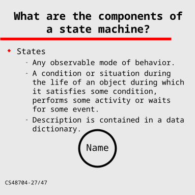
What are the components of a state machine?
States– Any observable mode of behavior.– A condition or situation during the life of an
object during which it satisfies some condition, performs some activity or waits for some event.
– Description is contained in a data dictionary.
Name
CS48704-28/47
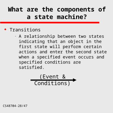
What are the components of a state machine?
Transitions– A relationship between two states indicating
that an object in the first state will perform certain actions and enter the second state when a specified event occurs and specified conditions are satisfied.
(Event & Conditions)
CS48704-29/47
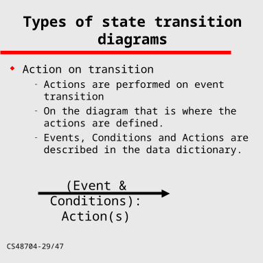
Types of state transition diagrams
Action on transition– Actions are performed on event transition– On the diagram that is where the actions are
defined.– Events, Conditions and Actions are described
in the data dictionary.
(Event & Conditions): Action(s)
CS48704-30/47
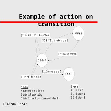
Example of action on transition
State 0
State 1
State 2
Events:T1 - T im e 1B1 - Button 1B2 - Button 2
T1: Set T im e to nn
(B1 & T1): Invoke state2
(B1 & NOT T1): No action.
B2: Invoke state0
B2: Invoke state 1
States:State 0: Norm ally idleState 1: ProcessingState 2: The blue screen of death
CS48704-31/47
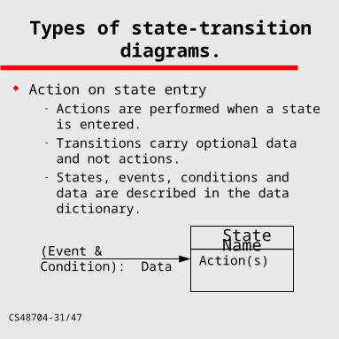
Types of state-transition diagrams.
Action on state entry– Actions are performed when a state is entered.– Transitions carry optional data and not actions.– States, events, conditions and data are
described in the data dictionary.
State Name
Action(s)(Event & Condition): Data
CS48704-32/47
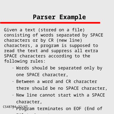
Parser Example
Given a text (stored on a file) consisting of words separated by SPACE characters or by CR (new line) characters, a program is supposed to read the text and suppress all extra SPACE characters according to the following rules:
– Words should be separated only by one
SPACE character, – Between a word and CR character there
should be no SPACE character,– New line cannot start with a SPACE character,– Program terminates on EOF (End of File)
character.
CS48704-33/47
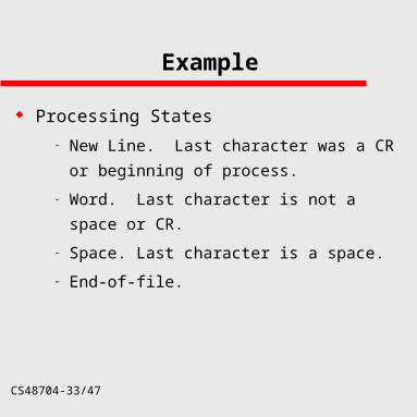
Example
Processing States
– New Line. Last character was a CR or
beginning of process.
– Word. Last character is not a space or CR.
– Space. Last character is a space.
– End-of-file.
CS48704-34/47
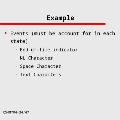
Example
Events (must be account for in each state)
– End-of-file indicator
– NL Character
– Space Character
– Text Characters
CS48704-35/47
Example
Actions
– Read Next
– Store Word
– Set Error
– List Stored Words
CS48704-36/47
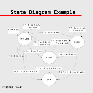
State Diagram Example
New Line
SP: Read Next, Set Error
EO F
Space
W ordCR: Read Next
Char: Read Next
EO F: L ist S tored W ords
SP: Read Next S tore W ord
EO F: L ist S tored W ords EO F: L ist S tored W ords
CR: Read Next S tore W ord
Char: Read Next
CR: Read Next
SP: Read Next, Set ErrorRead Next
CS48704-37/47
Analysis Modeling Software models must represent:
– the information that the sftwr acts on– the function that enable action – and overall system behavior
Requirements Models Roles: – Understand the information, function, behavior
and information in the system– Focal Point for the review - Avoids lots of wrds
help deal with complexity of problem– Become foundation for design process

CS48704-38/47
High-Level Modeling Tools System Modeling
– System Context Diagram– Partitioning
Data Modeling – Entity-Relation - Data objects and their
relationships Information flow diagrams
– Data flow diagrams - how data transforms in system- how functions transform data
Control Specifications– State diagrams - how system behaves
as result of external events.


![[PRINT] Lash Catalogue OCT 2018 · Lash extension is the new beauty must-have for modern women. • ... Only one lash extensions is glued on one original lash, creating a natural](https://img.pdfslide.us/doc/110x75/5e1f4bb7afe75b4c2863b493/print-lash-catalogue-oct-2018-lash-extension-is-the-new-beauty-must-have-for-modern.jpg)