Embed Size (px)
Citation preview
CS234 – Internet Technology
Tuesdays, Thursdays 3:30-4:50p.m.
Prof. Nalini [email protected]
(with slides from Kurose/Ross book, Prof. Zhang -UMN, Van Jacobsen’s clean slate design talk
Prof. Scott Jordon -UCI etc.)
1. Internet - Traffic measurements(Tue-Week 2)2. Web Caching (Thu-Week 2)3. Unstructured P2P 4. Structured P2P5. Application Layer Multicasting6. Multimedia Networking Systems7. QoS based Streaming8. Cellular Networks9. WiFi Networks10. WiFi Ad Hoc Networks11. Disruption Tolerant Networks12. Sensor Networks13. Pervasive Networking Technologies14. Smartphone Power Awareness15. Hybrid Networks16. Mobile Cloud Computing
Class Presentation Topics
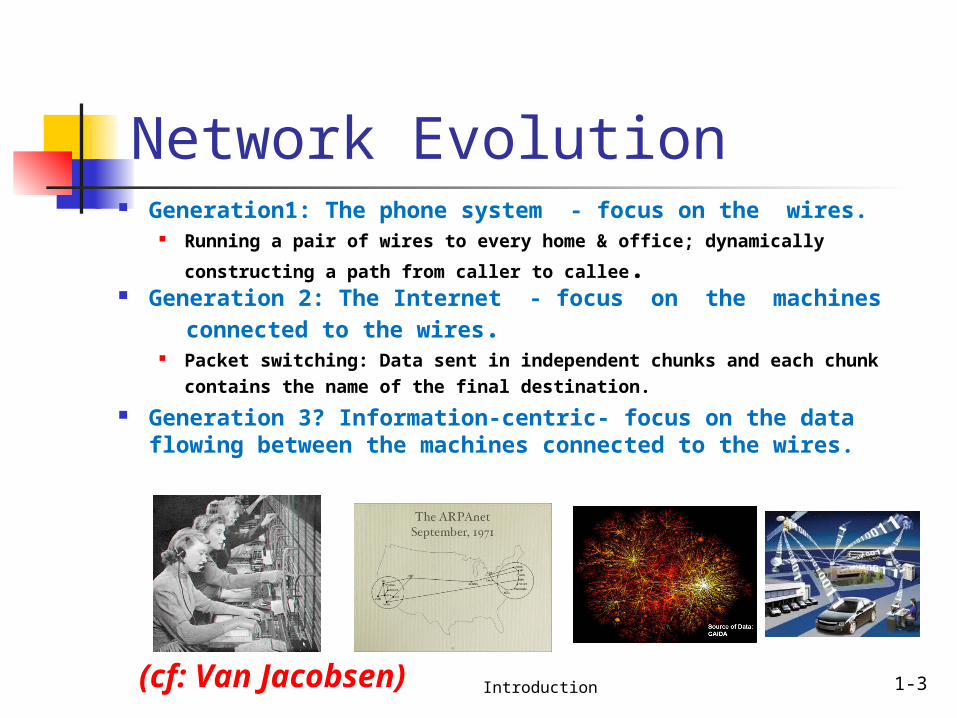
Network Evolution Generation1: The phone system - focus on the wires.
Running a pair of wires to every home & office; dynamically
constructing a path from caller to callee. Generation 2: The Internet - focus on the machines connected to the wires.
Packet switching: Data sent in independent chunks and each chunk contains the name of the final destination.
Generation 3? Information-centric- focus on the data flowing between the machines connected to the wires.
Introduction 1-3(cf: Van Jacobsen)
CSci5221: Zhi-Li Zhang Internet Design 4
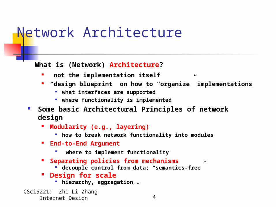
Network Architecture
What is (Network) Architecture? not the implementation itself “design blueprint” on how to “organize” implementations
what interfaces are supported where functionality is implemented
Some basic Architectural Principles of network design Modularity (e.g., layering)
how to break network functionality into modules End-to-End Argument
where to implement functionality Separating policies from mechanisms
decouple control from data; “semantics-free” Design for scale
hierarchy, aggregation, …
Chapter 1,2Introduction, Applications
Computer Networking: A Top Down Approach ,5th edition. Jim Kurose, Keith RossAddison-Wesley, April 2009.
A note on the use of these ppt slides:We’re making these slides freely available to all (faculty, students, readers). They’re in PowerPoint form so you can add, modify, and delete slides (including this one) and slide content to suit your needs. They obviously represent a lot of work on our part. In return for use, we only ask the following: If you use these slides (e.g., in a class) in substantially unaltered form, that you mention their source (after all, we’d like people to use our book!) If you post any slides in substantially unaltered form on a www site, that you note that they are adapted from (or perhaps identical to) our slides, and note our copyright of this material.
Thanks and enjoy! JFK/KWR
All material copyright 1996-2010J.F Kurose and K.W. Ross, All Rights Reserved
Introduction 1-5
Chapter 1: roadmap
1.1 What is the Internet?1.2 Network edge
end systems, access networks, links
1.3 Network core circuit switching, packet switching, network structure
1.4 Delay, loss and throughput in packet-switched networks
1.5 Protocol layers, service models1.6 Networks under attack: security1.7 History
Introduction 1-6
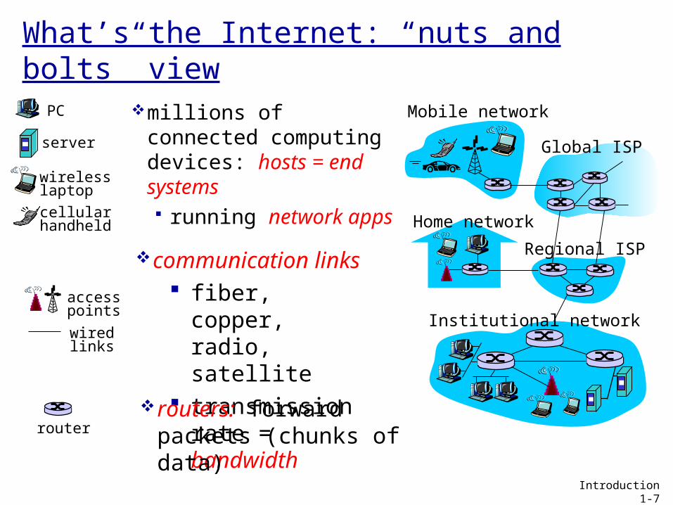
What’s the Internet: “nuts and bolts” view
millions of connected computing devices: hosts = end systems running network
apps Home network
Institutional network
Mobile network
Global ISP
Regional ISP
router
PC
server
wirelesslaptop
cellular handheld
wiredlinks
access points
communication links
fiber, copper, radio, satellite
transmission rate = bandwidth
routers: forward packets (chunks of data)
Introduction 1-7
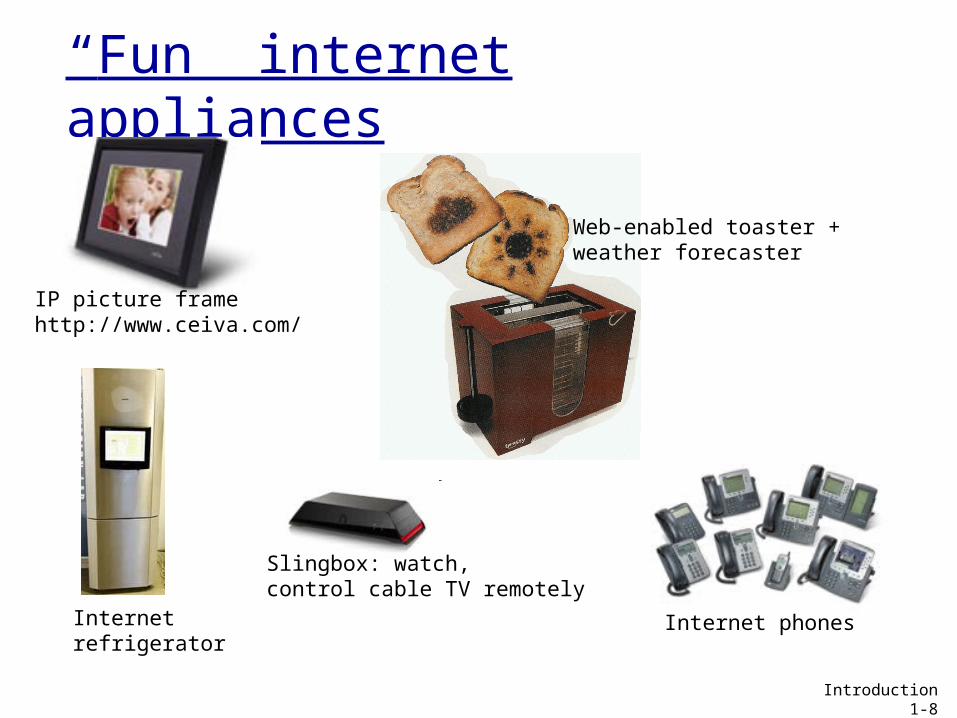
“Fun” internet appliances
IP picture framehttp://www.ceiva.com/
Web-enabled toaster +weather forecaster
Internet phonesInternet refrigerator
Slingbox: watch,control cable TV remotely
Introduction 1-8
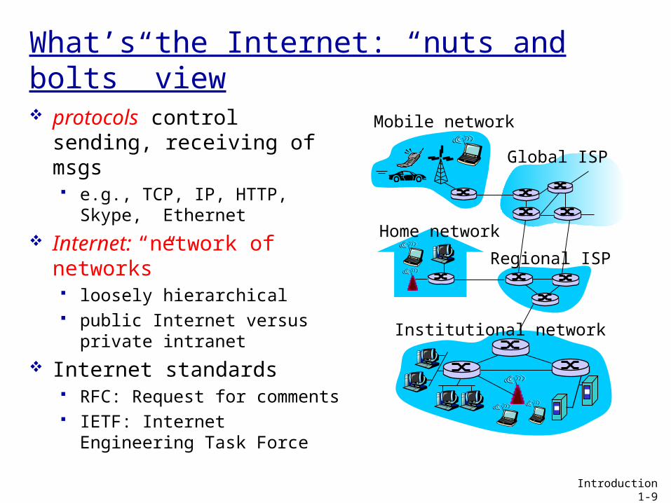
What’s the Internet: “nuts and bolts” view protocols control sending,
receiving of msgs e.g., TCP, IP, HTTP, Skype,
Ethernet Internet: “network of
networks” loosely hierarchical public Internet versus
private intranet Internet standards
RFC: Request for comments IETF: Internet Engineering
Task Force
Home network
Institutional network
Mobile network
Global ISP
Regional ISP
Introduction 1-9
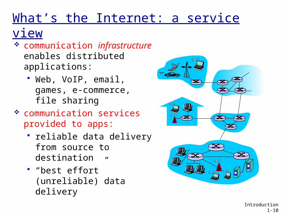
What’s the Internet: a service view communication
infrastructure enables distributed applications: Web, VoIP, email, games,
e-commerce, file sharing communication services
provided to apps: reliable data delivery
from source to destination
“best effort” (unreliable) data delivery
Introduction 1-10
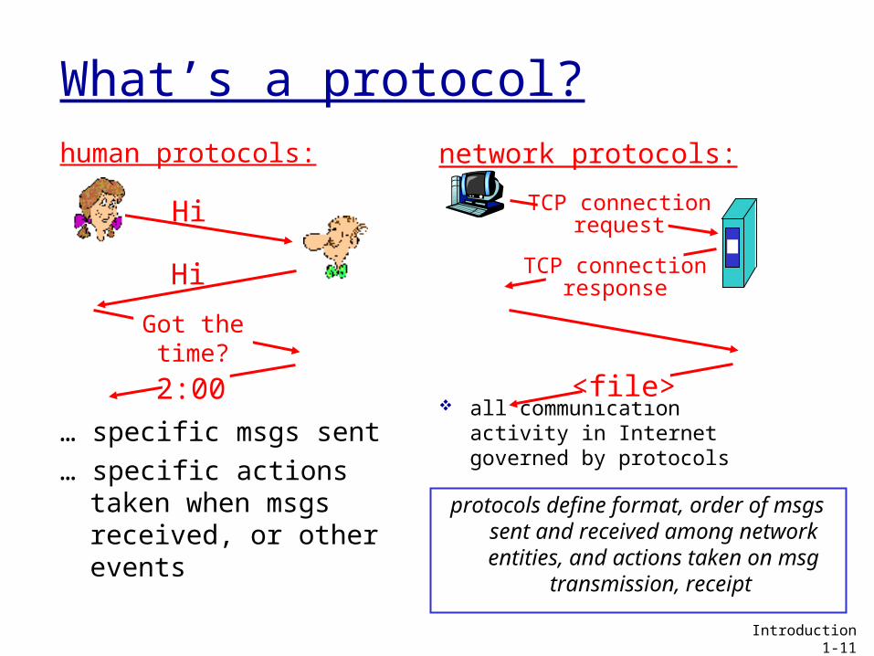
What’s a protocol?human protocols:
… specific msgs sent… specific actions
taken when msgs received, or other events
network protocols:
all communication activity in Internet governed by protocols
protocols define format, order of msgs sent and received among network entities, and actions taken on msg transmission,
receipt Introduction 1-11
Hi
Hi
Got thetime?
2:00
TCP connectionresponse
<file>
TCP connectionrequest
Chapter 1: roadmap
1.1 What is the Internet?1.2 Network edge
end systems, access networks, links
1.3 Network core circuit switching, packet switching, network structure
1.4 Delay, loss and throughput in packet-switched networks
1.5 Protocol layers, service models1.7 History
Introduction 1-12
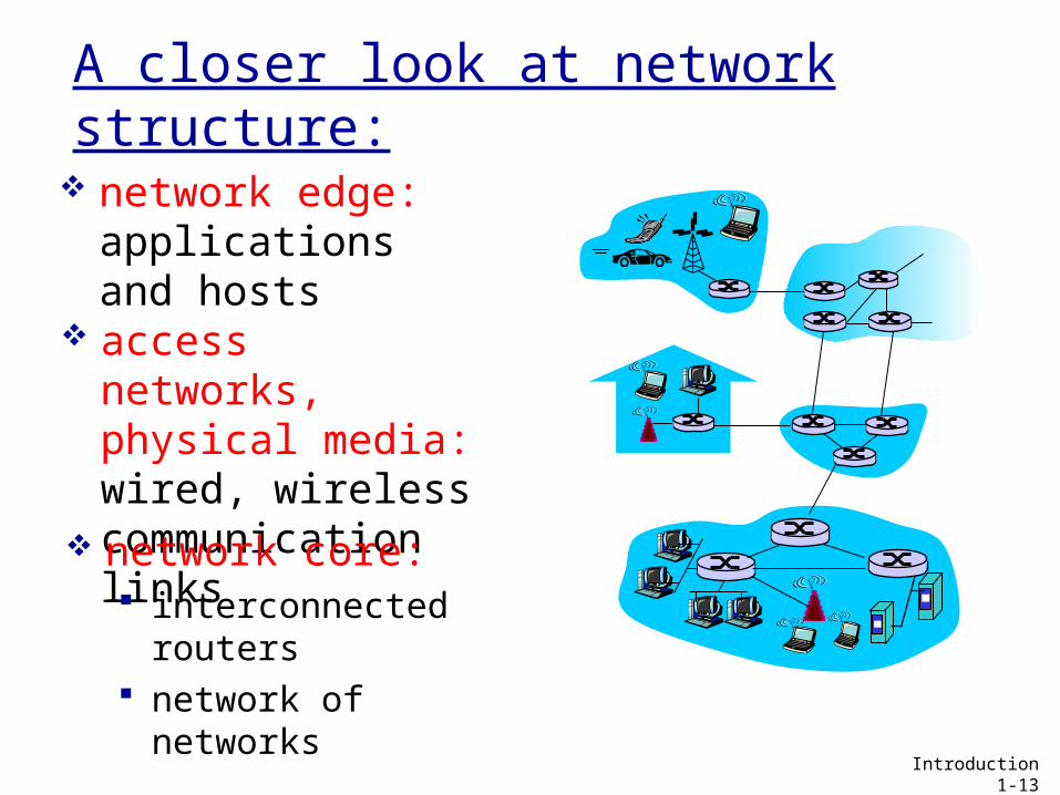
A closer look at network structure:
network edge: applications and hosts
access networks, physical media: wired, wireless communication links network core: interconnected
routers network of
networks Introduction 1-13
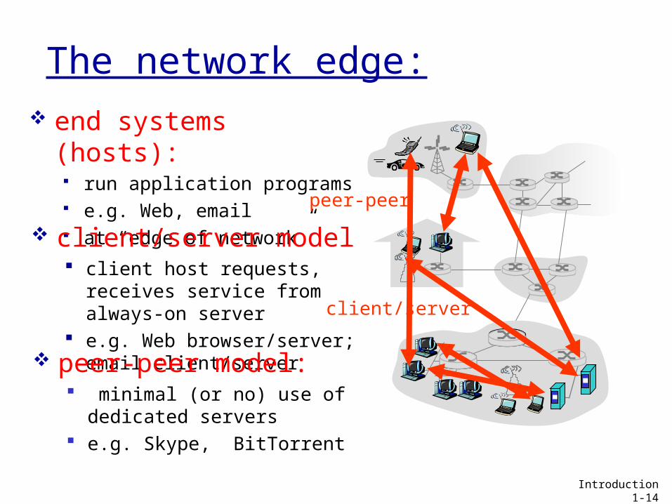
The network edge: end systems (hosts):
run application programs e.g. Web, email at “edge of network”
client/server
peer-peer
client/server model client host requests,
receives service from always-on server
e.g. Web browser/server; email client/server peer-peer model:
minimal (or no) use of dedicated servers
e.g. Skype, BitTorrent
Introduction 1-14
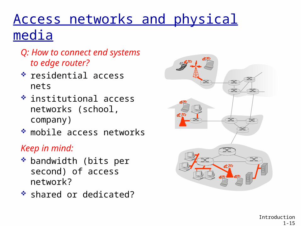
Access networks and physical media
Q: How to connect end systems to edge router?
residential access nets institutional access
networks (school, company)
mobile access networks
Keep in mind: bandwidth (bits per
second) of access network?
shared or dedicated? Introduction 1-15
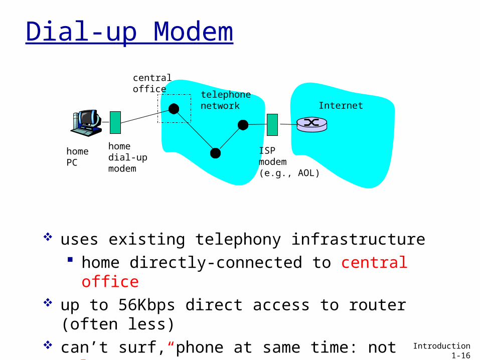
telephonenetwork Internet
homedial-upmodem
ISPmodem(e.g., AOL)
homePC
central office
uses existing telephony infrastructure home directly-connected to central office
up to 56Kbps direct access to router (often less) can’t surf, phone at same time: not “always on”
Dial-up Modem
Introduction 1-16
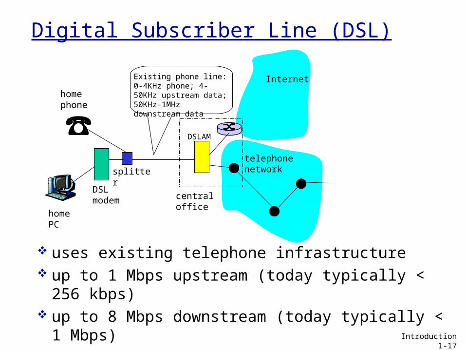
telephonenetwork
DSLmodem
homePC
homephone
Internet
DSLAM
Existing phone line:0-4KHz phone; 4-50KHz upstream data; 50KHz-1MHz downstream data
splitter
centraloffice
Digital Subscriber Line (DSL)
uses existing telephone infrastructure up to 1 Mbps upstream (today typically < 256
kbps) up to 8 Mbps downstream (today typically < 1
Mbps) dedicated physical line to telephone central office
Introduction 1-17
Residential access: cable modems
uses cable TV infrastructure, rather than telephone infrastructure
HFC: hybrid fiber coax asymmetric: up to 30Mbps downstream,
2 Mbps upstream network of cable, fiber attaches homes to
ISP router homes share access to router unlike DSL, which has dedicated access
Introduction 1-18
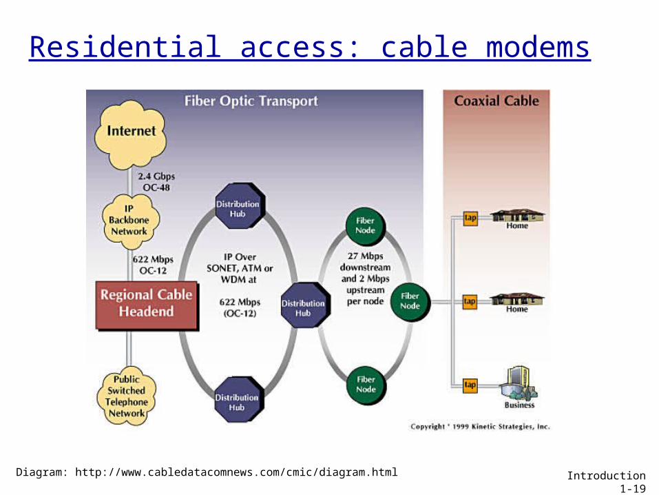
Residential access: cable modems
Diagram: http://www.cabledatacomnews.com/cmic/diagram.html Introduction 1-19
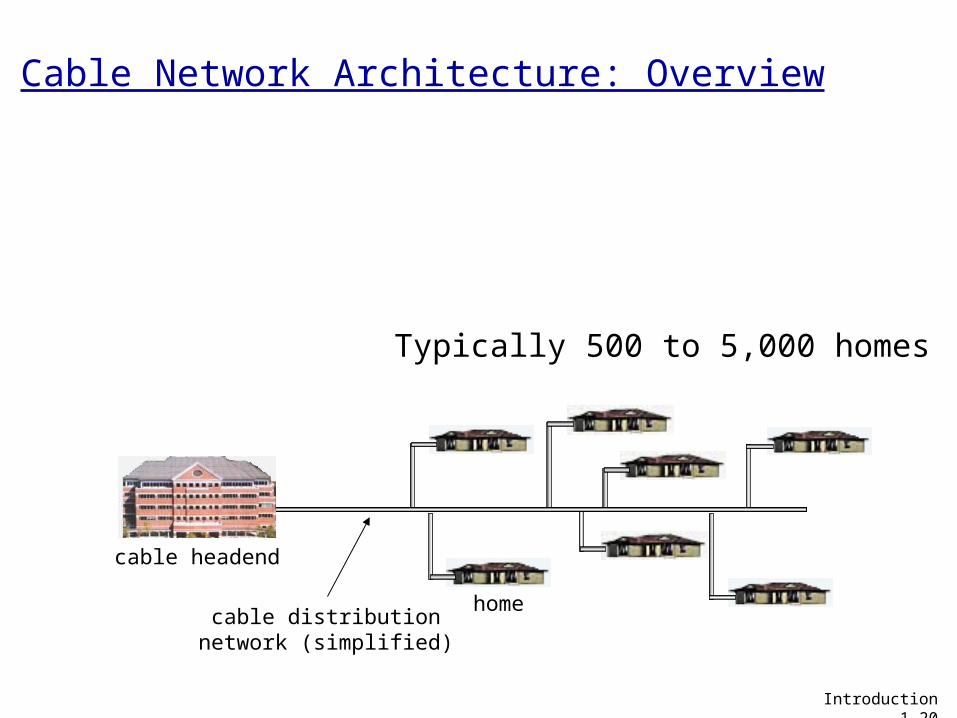
home
cable headend
cable distributionnetwork (simplified)
Typically 500 to 5,000 homes
Introduction 1-20
Cable Network Architecture: Overview
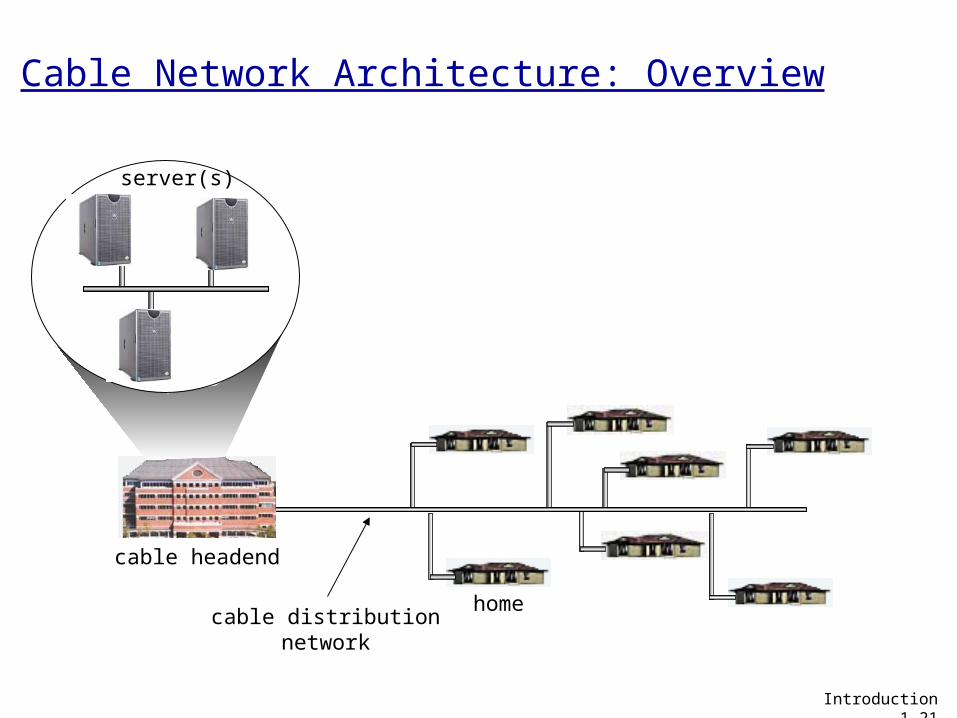
home
cable headend
cable distributionnetwork
server(s)
Introduction 1-21
Cable Network Architecture: Overview
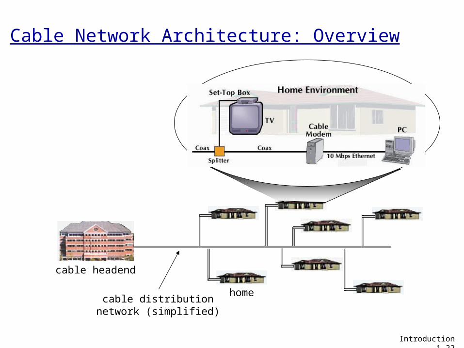
Cable Network Architecture: Overview
home
cable headend
cable distributionnetwork (simplified)
Introduction 1-22
home
cable headend
cable distributionnetwork
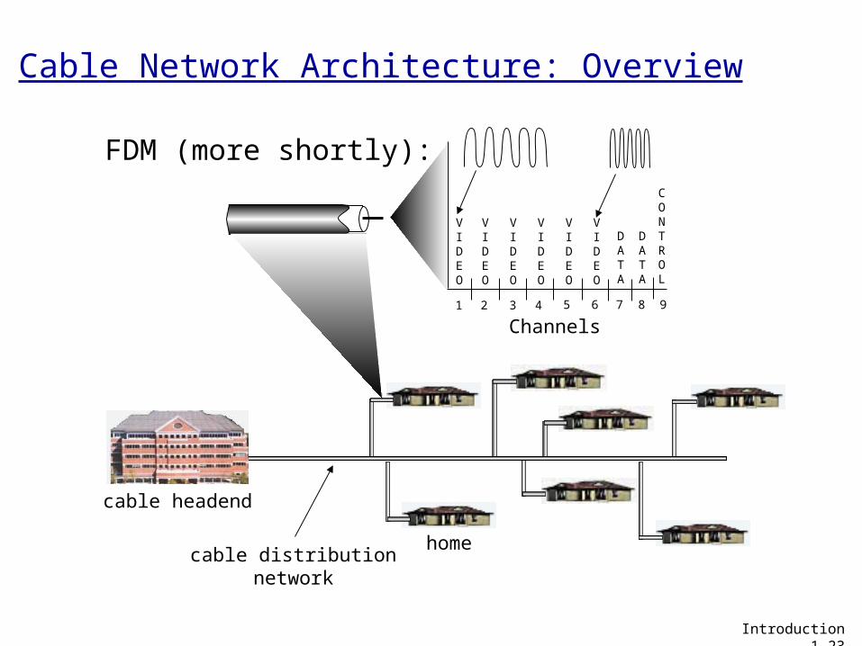
Channels
VIDEO
VIDEO
VIDEO
VIDEO
VIDEO
VIDEO
DATA
DATA
CONTROL
1 2 3 4 5 6 7 8 9
FDM (more shortly):
Introduction 1-23
Cable Network Architecture: Overview
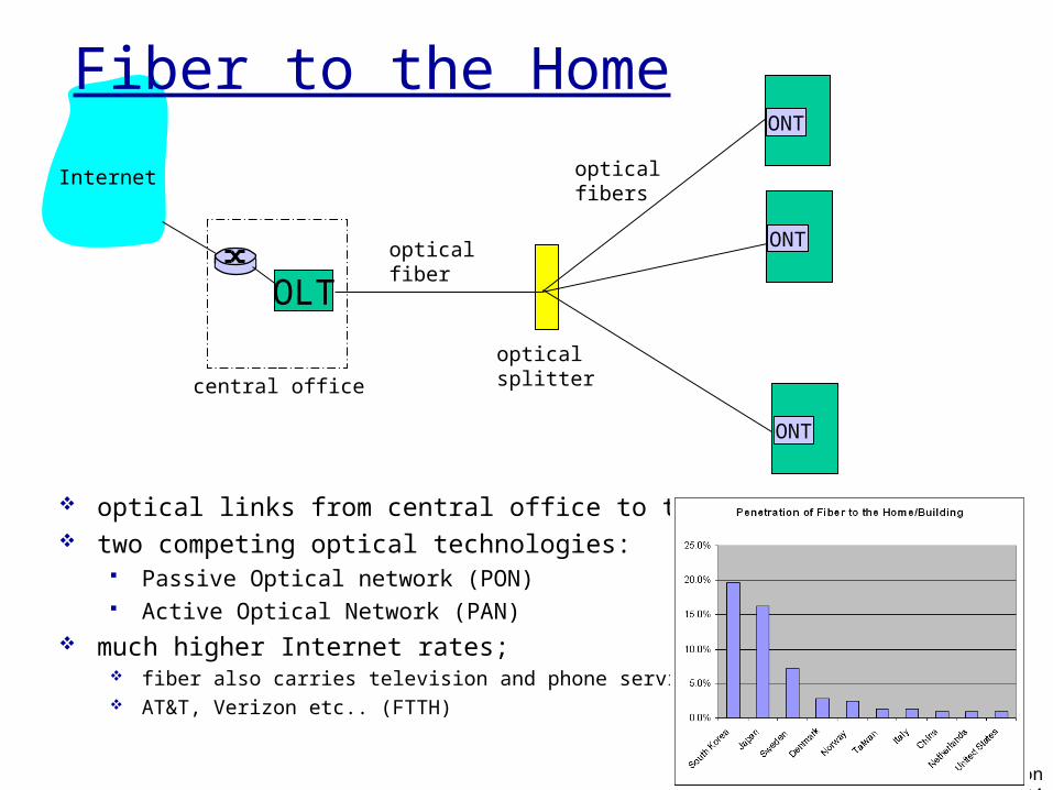
ONT
OLT
central office
opticalsplitter
ONT
ONT
opticalfiber
opticalfibers
Internet
Fiber to the Home
optical links from central office to the home two competing optical technologies:
Passive Optical network (PON) Active Optical Network (PAN)
much higher Internet rates; fiber also carries television and phone services AT&T, Verizon etc.. (FTTH)
Introduction 1-24
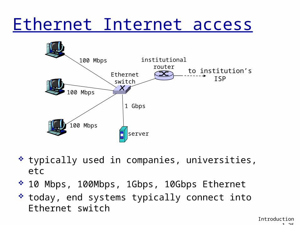
100 Mbps
100 Mbps
100 Mbps
1 Gbps
server
Ethernetswitch
institutionalrouter
to institution’sISP
Ethernet Internet access
typically used in companies, universities, etc 10 Mbps, 100Mbps, 1Gbps, 10Gbps Ethernet today, end systems typically connect into
Ethernet switch
Introduction 1-25
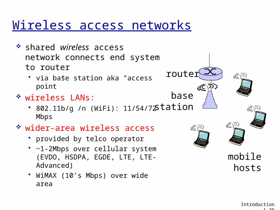
Wireless access networks
shared wireless access network connects end system to router via base station aka “access
point” wireless LANs:
802.11b/g /n (WiFi): 11/54/72 Mbps
wider-area wireless access provided by telco operator ~1-2Mbps over cellular system
(EVDO, HSDPA, EGDE, LTE, LTE-Advanced)
WiMAX (10’s Mbps) over wide area
basestation
mobilehosts
router
Introduction 1-26
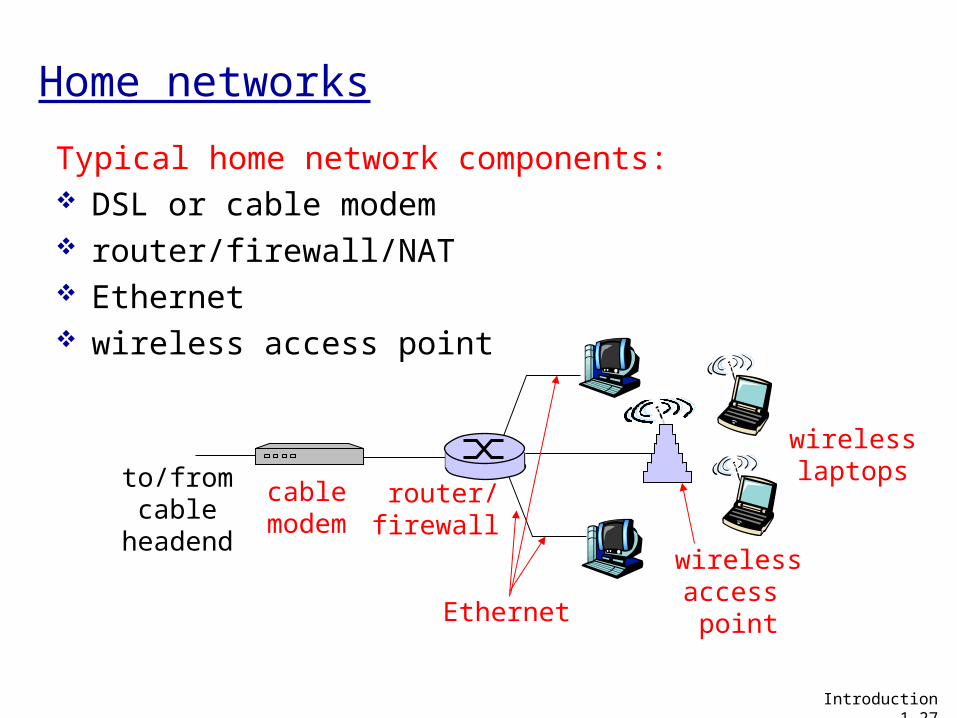
Home networks
Typical home network components: DSL or cable modem router/firewall/NAT Ethernet wireless access point
wirelessaccess point
wirelesslaptops
router/firewall
cablemodem
to/fromcable
headend
Ethernet
Introduction 1-27
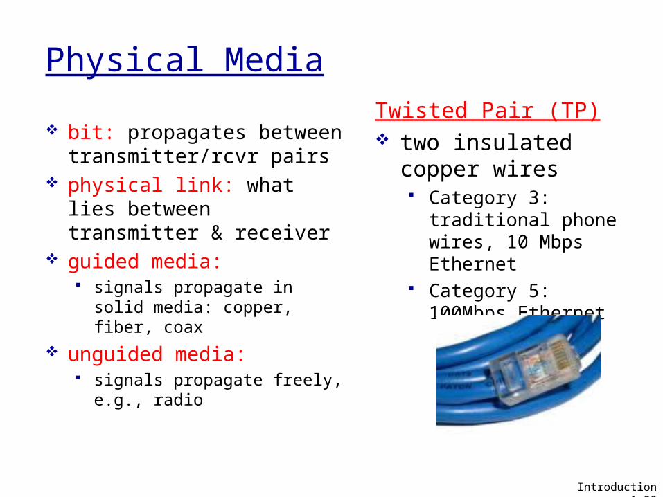
Physical Media
bit: propagates betweentransmitter/rcvr pairs
physical link: what lies between transmitter & receiver
guided media: signals propagate in solid
media: copper, fiber, coax unguided media:
signals propagate freely, e.g., radio
Twisted Pair (TP) two insulated copper
wires Category 3: traditional
phone wires, 10 Mbps Ethernet
Category 5: 100Mbps Ethernet
Introduction 1-28
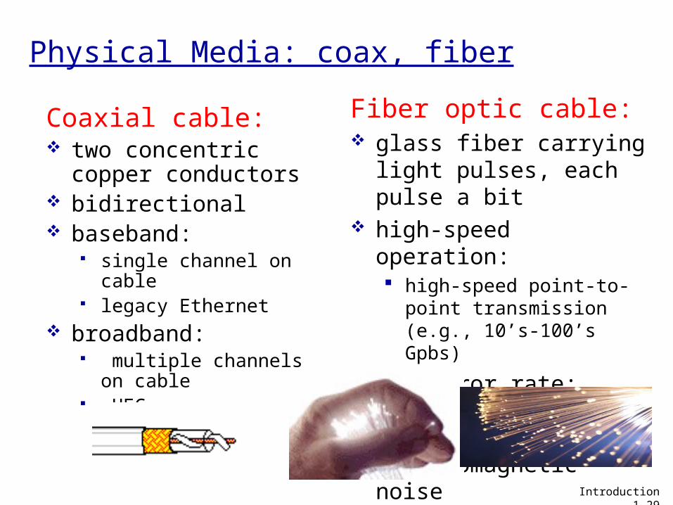
Physical Media: coax, fiber
Coaxial cable: two concentric copper
conductors bidirectional baseband:
single channel on cable legacy Ethernet
broadband: multiple channels on
cable HFC
Fiber optic cable: glass fiber carrying
light pulses, each pulse a bit
high-speed operation: high-speed point-to-point
transmission (e.g., 10’s-100’s Gpbs)
low error rate: repeaters spaced far apart ; immune to electromagnetic noise
Introduction 1-29
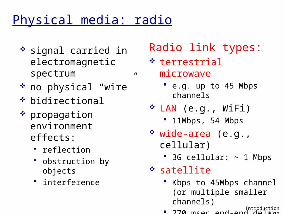
Physical media: radio
signal carried in electromagnetic spectrum
no physical “wire” bidirectional propagation
environment effects: reflection obstruction by objects interference
Radio link types: terrestrial microwave
e.g. up to 45 Mbps channels
LAN (e.g., WiFi) 11Mbps, 54 Mbps
wide-area (e.g., cellular) 3G cellular: ~ 1 Mbps
satellite Kbps to 45Mbps channel
(or multiple smaller channels)
270 msec end-end delay geosynchronous versus low
altitude Introduction 1-30
Chapter 1: roadmap
1.1 What is the Internet?1.2 Network edge
end systems, access networks, links
1.3 Network core circuit switching, packet switching, network structure
1.4 Delay, loss and throughput in packet-switched networks
1.5 Protocol layers, service models1.6 Networks under attack: security1.7 History
Introduction 1-31
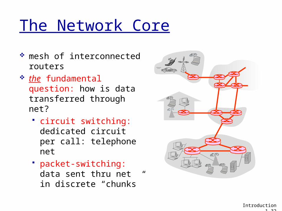
The Network Core
mesh of interconnected routers
the fundamental question: how is data transferred through net? circuit switching:
dedicated circuit per call: telephone net
packet-switching: data sent thru net in discrete “chunks”
Introduction 1-32

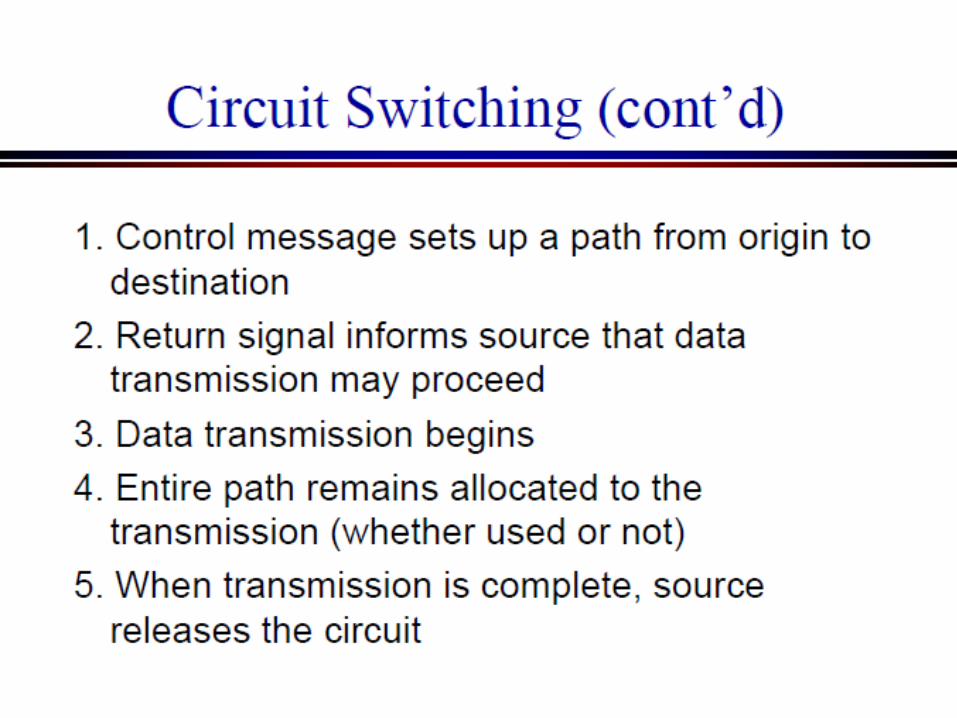
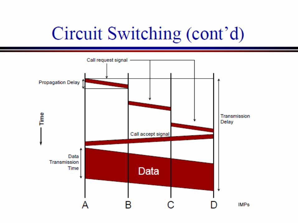
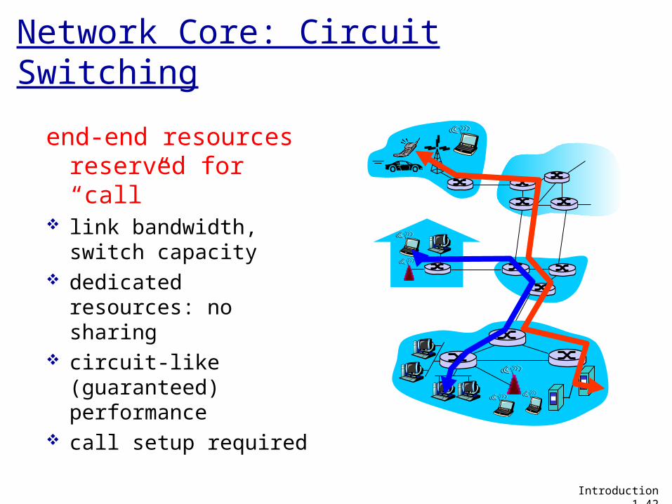
Network Core: Circuit Switching
end-end resources reserved for “call”
link bandwidth, switch capacity
dedicated resources: no sharing
circuit-like (guaranteed) performance
call setup required
Introduction 1-42
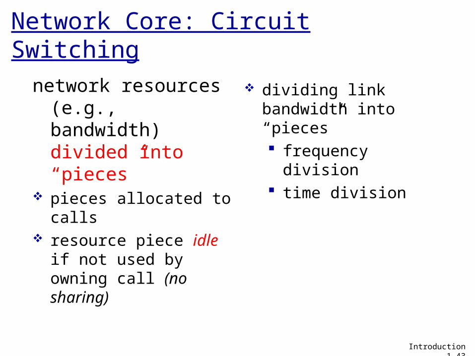
Network Core: Circuit Switching
network resources (e.g., bandwidth) divided into “pieces”
pieces allocated to calls
resource piece idle if not used by owning call (no sharing)
dividing link bandwidth into “pieces” frequency division time division
Introduction 1-43
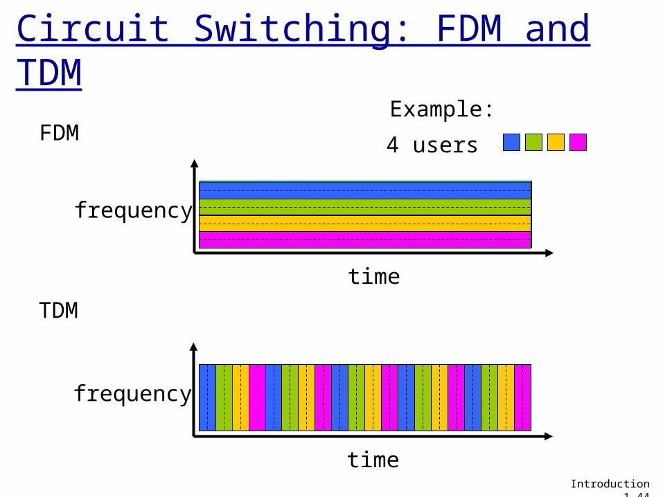
Circuit Switching: FDM and TDM
FDM
frequency
time
TDM
frequency
time
4 users
Example:
Introduction 1-44
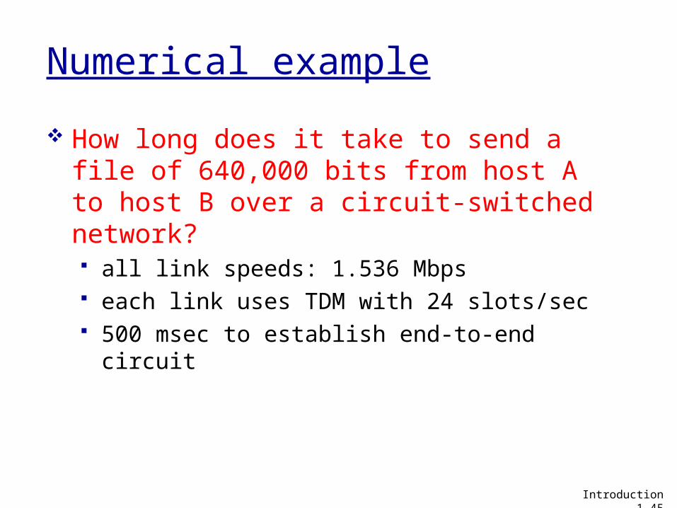
Numerical example
How long does it take to send a file of 640,000 bits from host A to host B over a circuit-switched network? all link speeds: 1.536 Mbps each link uses TDM with 24 slots/sec 500 msec to establish end-to-end circuit
Introduction 1-45
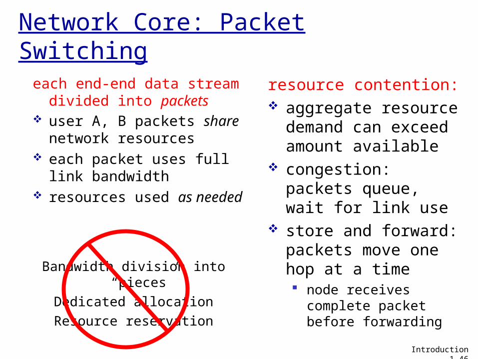
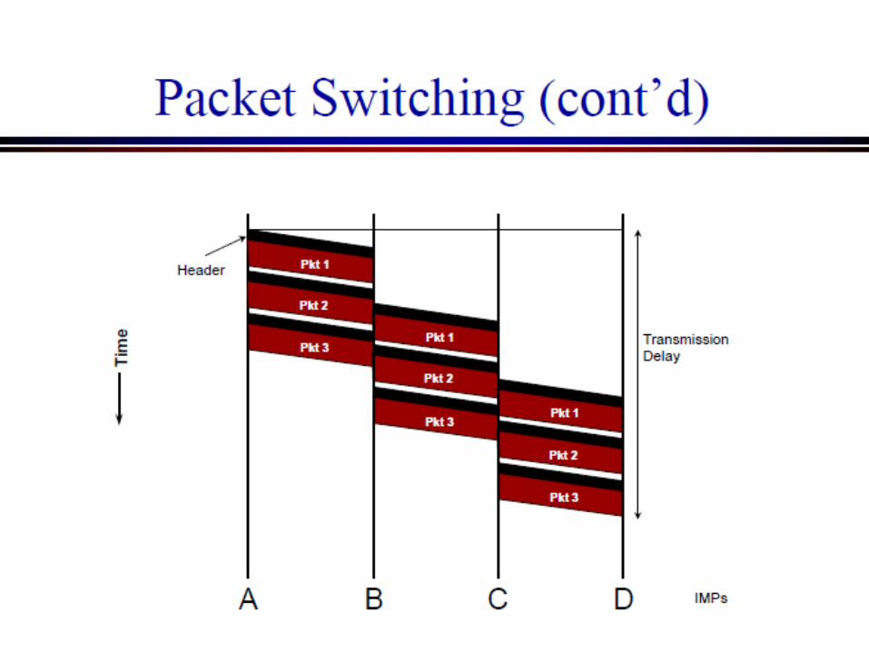
Network Core: Packet Switching
each end-end data stream divided into packets
user A, B packets share network resources
each packet uses full link bandwidth
resources used as needed
resource contention: aggregate resource
demand can exceed amount available
congestion: packets queue, wait for link use
store and forward: packets move one hop at a time node receives
complete packet before forwarding
Bandwidth division into “pieces”
Dedicated allocationResource reservation
Introduction 1-46
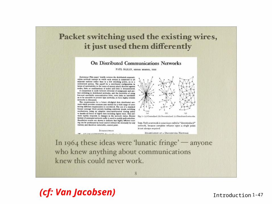
Introduction 1-47(cf: Van Jacobsen)
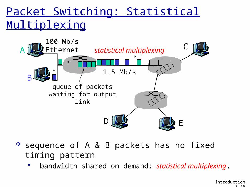
Packet Switching: Statistical Multiplexing
sequence of A & B packets has no fixed timing pattern bandwidth shared on demand: statistical multiplexing.
A
B
C100 Mb/sEthernet
1.5 Mb/s
D E
statistical multiplexing
queue of packetswaiting for output
link
Introduction 1-48
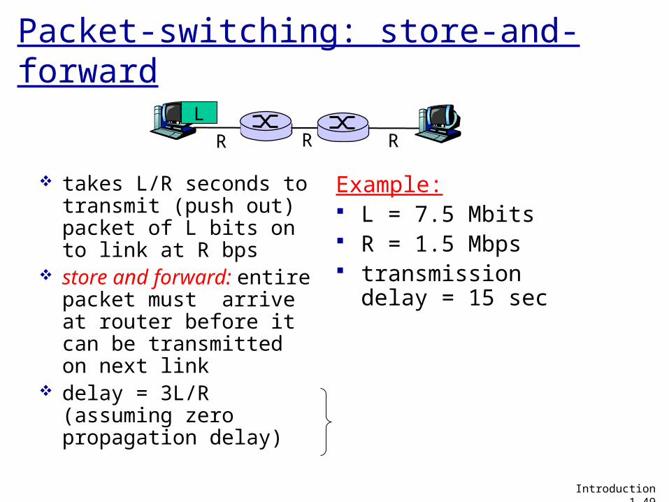
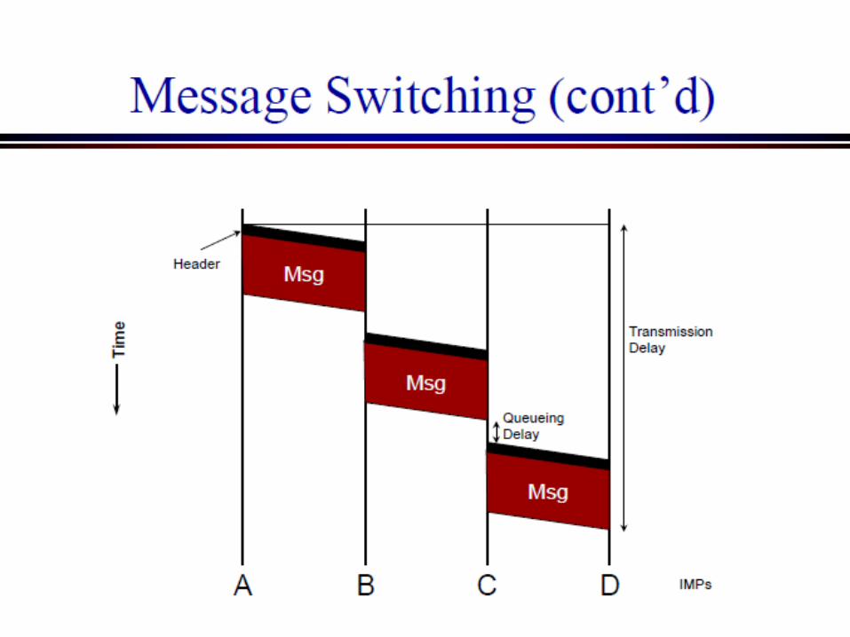
Packet-switching: store-and-forward
takes L/R seconds to transmit (push out) packet of L bits on to link at R bps
store and forward: entire packet must arrive at router before it can be transmitted on next link
delay = 3L/R (assuming zero propagation delay)
Example: L = 7.5 Mbits R = 1.5 Mbps transmission delay =
15 sec
R R RL
Introduction 1-49
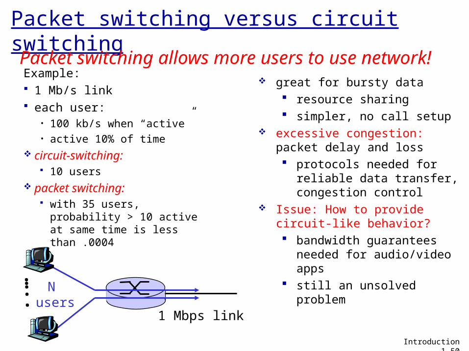
Packet switching versus circuit switching
Example: 1 Mb/s link each user:
• 100 kb/s when “active”• active 10% of time
circuit-switching: 10 users
packet switching: with 35 users, probability
> 10 active at same time is less than .0004
Packet switching allows more users to use network!
N users
1 Mbps link
Introduction 1-50
…..
great for bursty data resource sharing simpler, no call setup
excessive congestion: packet delay and loss protocols needed for
reliable data transfer, congestion control
Issue: How to provide circuit-like behavior? bandwidth guarantees
needed for audio/video apps
still an unsolved problem
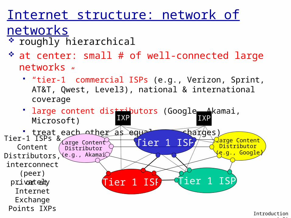
Internet structure: network of networks roughly hierarchical at center: small # of well-connected large networks
“tier-1” commercial ISPs (e.g., Verizon, Sprint, AT&T, Qwest, Level3), national & international coverage
large content distributors (Google, Akamai, Microsoft) treat each other as equals (no charges)
Tier 1 ISP Tier 1 ISP
Introduction 1-51
Large Content Distributor
(e.g., Google)
Large Content Distributor
(e.g., Akamai)
IXP IXP
Tier 1 ISPTier-1 ISPs &Content
Distributors, interconnect
(peer) privately … or at Internet
Exchange Points IXPs
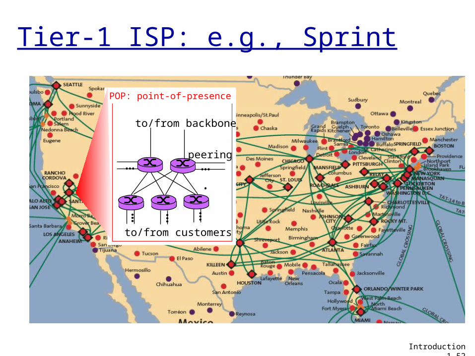
Tier-1 ISP: e.g., Sprint
…
to/from customers
peering
to/from backbone
….
………
POP: point-of-presence
Introduction 1-52
CSci5221: Introduction 53
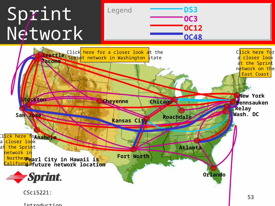
SprintNetwork
Click here fora closer lookat the Sprint
network on theEast Coast
Click here fora closer lookat the Sprintnetwork inNorthernCalifornia
Pearl City in Hawaii isa future network location
Click here for a closer look at theSprint network in Washington state
Legend DS3OC3OC12OC48
Seattle
Atlanta
Chicago
Roachdale
Stockton
San Jose
Anaheim
Fort Worth
Orlando
Kansas City
CheyenneNew York
PennsaukenRelay
Wash. DC
Tacoma
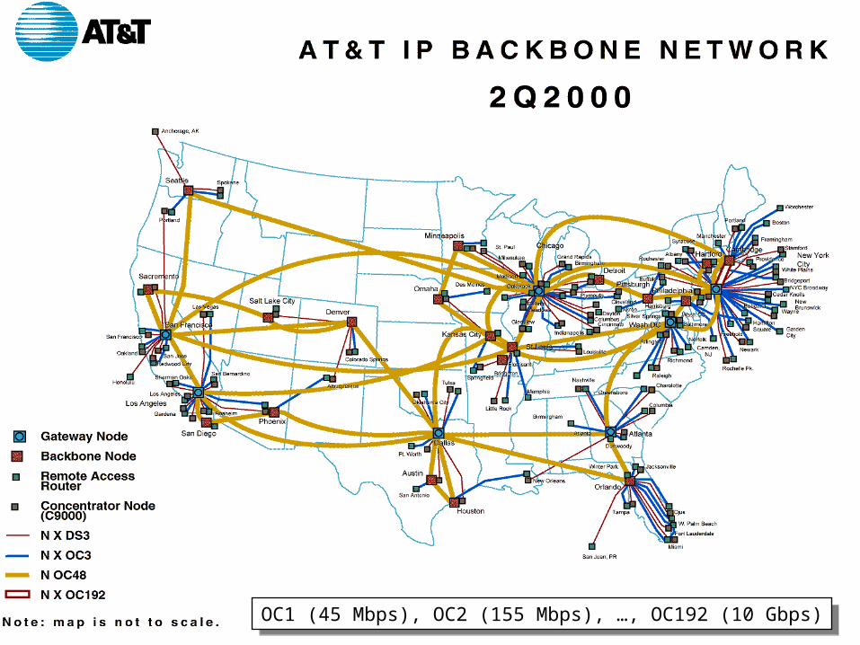
CSci5221: Introduction 54OC1 (45 Mbps), OC2 (155 Mbps), …, OC192 (10 Gbps)OC1 (45 Mbps), OC2 (155 Mbps), …, OC192 (10 Gbps)
CSci5221: Introduction 55
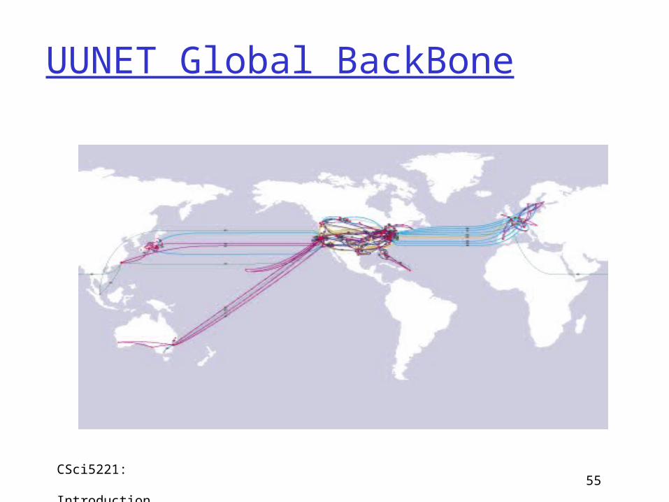
UUNET Global BackBone
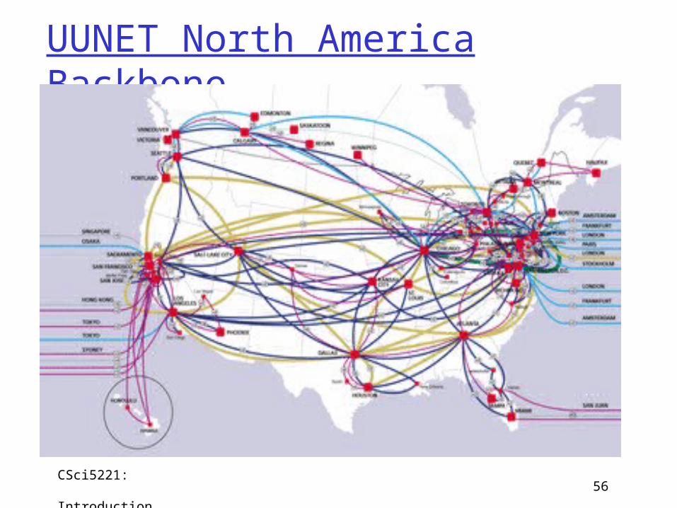
CSci5221: Introduction 56
UUNET North America Backbone
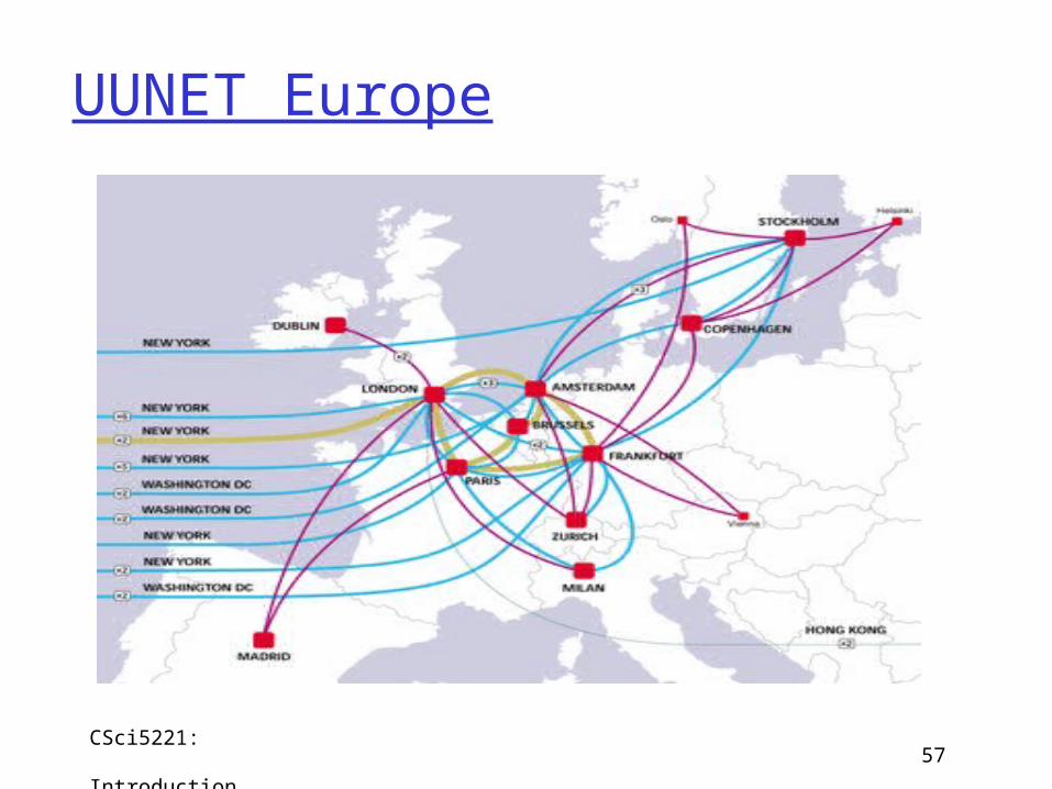
CSci5221: Introduction 57
UUNET Europe
Tier 2ISP
Internet structure: network of networks
Introduction 1-58
Tier 1 ISP Tier 1 ISP
Large Content Distributor
(e.g., Google)
Large Content Distributor
(e.g., Akamai)
IXP IXP
Tier 1 ISP
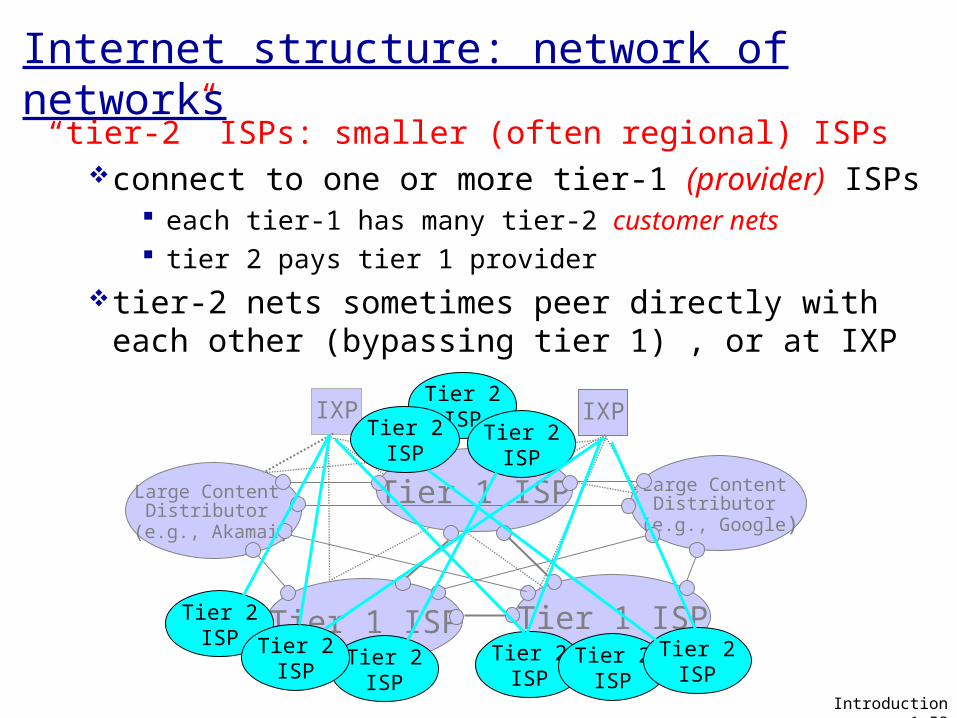
“tier-2” ISPs: smaller (often regional) ISPsconnect to one or more tier-1 (provider) ISPs
each tier-1 has many tier-2 customer nets tier 2 pays tier 1 provider
tier-2 nets sometimes peer directly with each other (bypassing tier 1) , or at IXP
Tier 2ISP
Tier 2ISP
Tier 2ISP
Tier 2ISP Tier 2
ISPTier 2
ISPTier 2
ISP
Tier 2ISP
Tier 2ISP
Internet structure: network of networks
Introduction 1-59
Tier 1 ISP Tier 1 ISP
Large Content Distributor
(e.g., Google)
Large Content Distributor
(e.g., Akamai)
IXP IXP
Tier 1 ISP
Tier 2ISP
Tier 2ISP
Tier 2ISP
Tier 2ISP Tier 2
ISPTier 2
ISPTier 2
ISP
Tier 2ISP
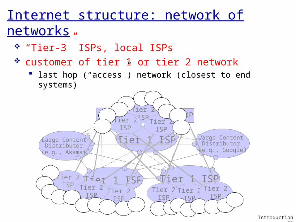
“Tier-3” ISPs, local ISPs customer of tier 1 or tier 2 network
last hop (“access”) network (closest to end systems)
Tier 2ISP
Internet structure: network of networks
Introduction 1-60
Tier 1 ISP Tier 1 ISP
Large Content Distributor
(e.g., Google)
Large Content Distributor
(e.g., Akamai)
IXP IXP
Tier 1 ISP
Tier 2ISP
Tier 2ISP
Tier 2ISP
Tier 2ISP Tier 2
ISPTier 2
ISPTier 2
ISP
Tier 2ISP
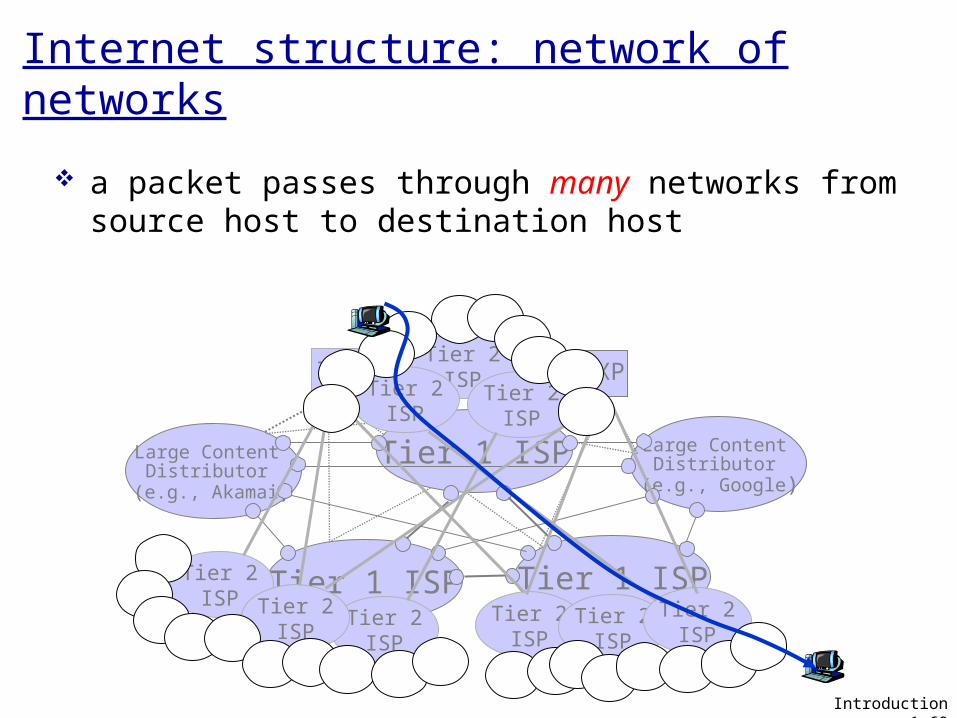
a packet passes through many networks from source host to destination host
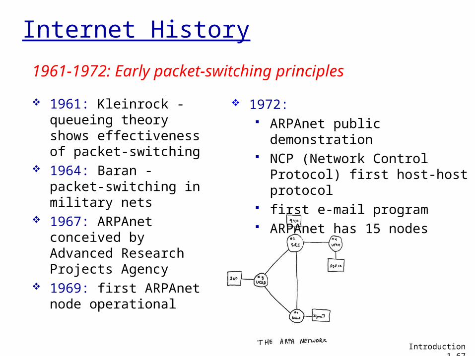
Internet History
1961: Kleinrock - queueing theory shows effectiveness of packet-switching
1964: Baran - packet-switching in military nets
1967: ARPAnet conceived by Advanced Research Projects Agency
1969: first ARPAnet node operational
1972: ARPAnet public
demonstration NCP (Network Control
Protocol) first host-host protocol
first e-mail program ARPAnet has 15 nodes
1961-1972: Early packet-switching principles
Introduction 1-67
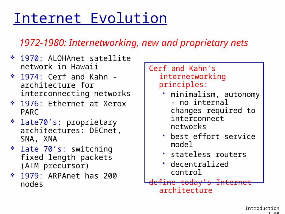
Internet Evolution
1970: ALOHAnet satellite network in Hawaii
1974: Cerf and Kahn - architecture for interconnecting networks
1976: Ethernet at Xerox PARC
late70’s: proprietary architectures: DECnet, SNA, XNA
late 70’s: switching fixed length packets (ATM precursor)
1979: ARPAnet has 200 nodes
Cerf and Kahn’s internetworking principles: minimalism,
autonomy - no internal changes required to interconnect networks
best effort service model
stateless routers decentralized control
define today’s Internet architecture
1972-1980: Internetworking, new and proprietary nets
Introduction 1-68
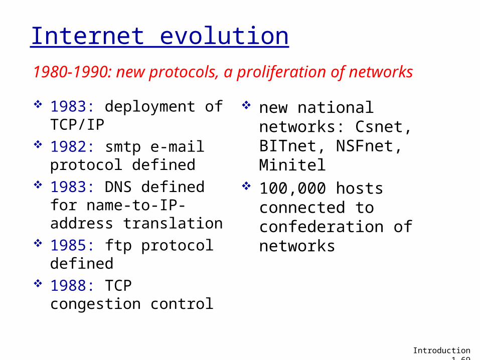
Internet evolution
1983: deployment of TCP/IP
1982: smtp e-mail protocol defined
1983: DNS defined for name-to-IP-address translation
1985: ftp protocol defined
1988: TCP congestion control
new national networks: Csnet, BITnet, NSFnet, Minitel
100,000 hosts connected to confederation of networks
1980-1990: new protocols, a proliferation of networks
Introduction 1-69

Internet Evolution
early 1990’s: ARPAnet decommissioned
1991: NSF lifts restrictions on commercial use of NSFnet (decommissioned, 1995)
early 1990s: Web hypertext [Bush 1945,
Nelson 1960’s] HTML, HTTP: Berners-Lee 1994: Mosaic, later Netscape late 1990’s:
commercialization of the Web
late 1990’s – 2000’s: more killer apps: instant
messaging, P2P file sharing
network security to forefront
est. 50 million host, 100 million+ users
backbone links running at Gbps
1990, 2000’s: commercialization, the Web, new apps
Introduction 1-70
Internet Evolution
2010: ~750 million hosts voice, video over IP P2P applications: BitTorrent
(file sharing) Skype (VoIP), PPLive (video)
more applications: YouTube, gaming, Twitter
wireless, mobility
Introduction 1-71
CSci5221: Internet Design 72
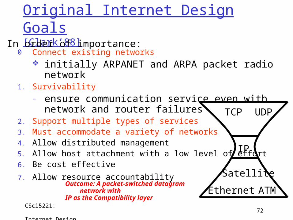
Original Internet Design Goals[Clark’88]
0 Connect existing networks initially ARPANET and ARPA packet radio
network1. Survivability
- ensure communication service even with network and router failures
2. Support multiple types of services3. Must accommodate a variety of networks4. Allow distributed management5. Allow host attachment with a low level of effort6. Be cost effective
7. Allow resource accountability
In order of importance:
IP
TCP UDP
ATM
Satellite
EthernetOutcome: A packet-switched datagram network with IP as the Compatibility layer
Motivation: Clean Slate design
Introduction 1-73
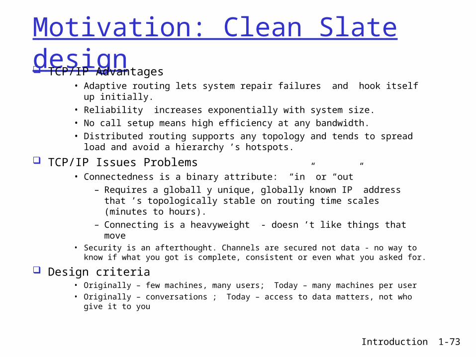
TCP/IP Advantages• Adaptive routing lets system repair failures and hook itself up
initially.• Reliability increases exponentially with system size.• No call setup means high efficiency at any bandwidth.• Distributed routing supports any topology and tends to spread
load and avoid a hierarchy ’s hotspots.
TCP/IP Issues Problems• Connectedness is a binary attribute: “in” or “out”
– Requires a globall y unique, globally known IP address that ’s topologically stable on routing time scales (minutes to hours).
– Connecting is a heavyweight - doesn ’t like things that move• Security is an afterthought. Channels are secured not data - no way to
know if what you got is complete, consistent or even what you asked for.
Design criteria• Originally – few machines, many users; Today – many machines per user• Originally – conversations ; Today – access to data matters, not who give
it to you
CSci5221: Internet Design 74
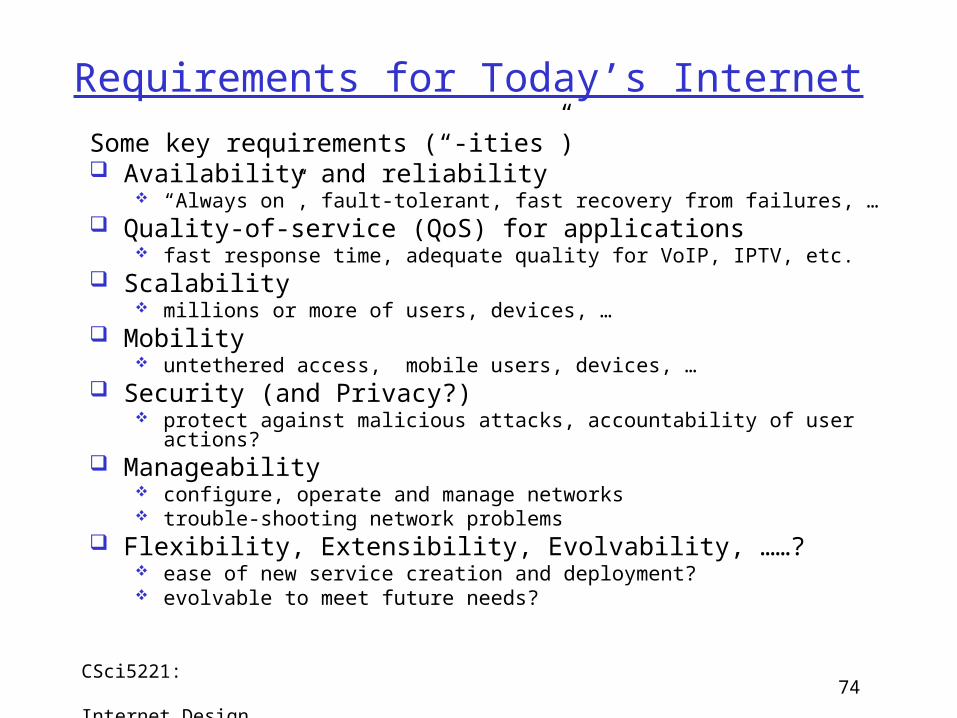
Requirements for Today’s Internet
Some key requirements (“-ities”) Availability and reliability
“Always on”, fault-tolerant, fast recovery from failures, … Quality-of-service (QoS) for applications
fast response time, adequate quality for VoIP, IPTV, etc. Scalability
millions or more of users, devices, … Mobility
untethered access, mobile users, devices, … Security (and Privacy?)
protect against malicious attacks, accountability of user actions? Manageability
configure, operate and manage networks trouble-shooting network problems
Flexibility, Extensibility, Evolvability, ……? ease of new service creation and deployment? evolvable to meet future needs?
Chapter 1: roadmap
1.1 What is the Internet?1.2 Network edge
end systems, access networks, links
1.3 Network core circuit switching, packet switching, network structure
1.4 Delay, loss and throughput in packet-switched networks
1.5 Protocol layers, service models1.6 Networks under attack: security1.7 History
Introduction 1-75
Protocol “Layers”
Networks are complex,
with many “pieces”: hosts routers links of various
media applications protocols hardware,
software
Question: Is there any hope of organizing structure of
network?
Or at least our discussion of networks?
Introduction 1-76
ticket (purchase)
baggage (check)
gates (load)
runway (takeoff)
airplane routing
departureairport
arrivalairport
intermediate air-trafficcontrol centers
airplane routing airplane routing
ticket (complain)
baggage (claim
gates (unload)
runway (land)
airplane routing
ticket
baggage
gate
takeoff/landing
airplane routing
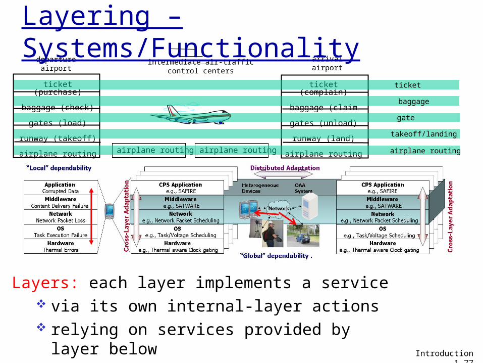
Layering – Systems/Functionality
Layers: each layer implements a service via its own internal-layer actions relying on services provided by layer below
Introduction 1-77
Why layering?
Dealing with complex systems: explicit structure allows identification,
relationship of complex system’s pieces layered reference model for discussion
modularization eases maintenance, updating of system change of implementation of layer’s service
transparent to rest of system e.g., change in gate procedure doesn’t
affect rest of system layering considered harmful?
Introduction 1-78
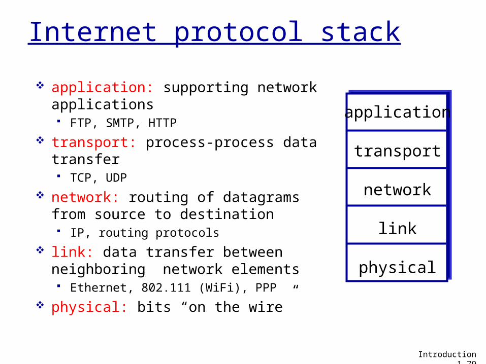
Internet protocol stack
application: supporting network applications FTP, SMTP, HTTP
transport: process-process data transfer TCP, UDP
network: routing of datagrams from source to destination IP, routing protocols
link: data transfer between neighboring network elements Ethernet, 802.111 (WiFi), PPP
physical: bits “on the wire”
application
transport
network
link
physical
Introduction 1-79
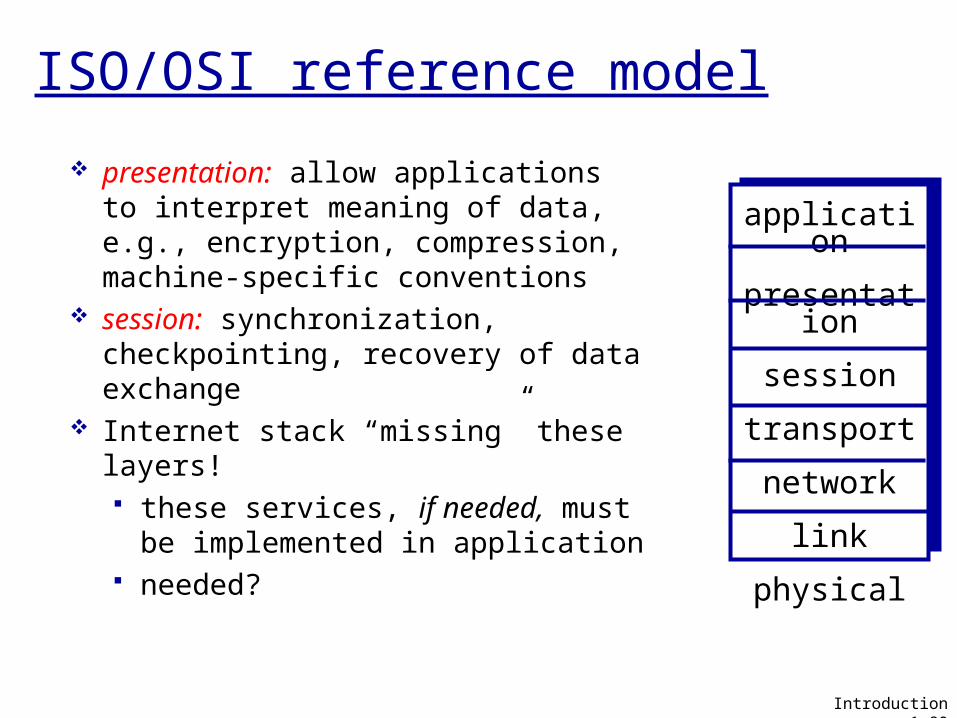
ISO/OSI reference model
presentation: allow applications to interpret meaning of data, e.g., encryption, compression, machine-specific conventions
session: synchronization, checkpointing, recovery of data exchange
Internet stack “missing” these layers! these services, if needed, must
be implemented in application needed?
application
presentation
session
transport
network
link
physical
Introduction 1-80
sourceapplicatio
ntransportnetwork
linkphysical
HtHn M
segment Ht
datagram
destination
application
transportnetwork
linkphysical
HtHnHl M
HtHn M
Ht M
M
networklink
physical
linkphysical
HtHnHl M
HtHn M
HtHn M
HtHnHl M
router
switch
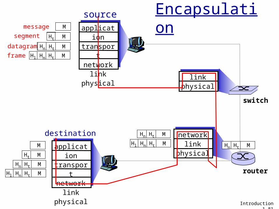
Encapsulationmessage M
Ht M
Hn
frame
Introduction 1-81
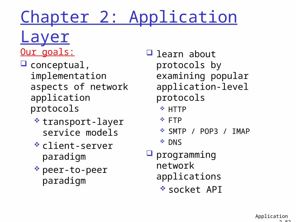
Chapter 2: Application LayerOur goals: conceptual,
implementation aspects of network application protocols transport-layer
service models client-server
paradigm peer-to-peer
paradigm
learn about protocols by examining popular application-level protocols HTTP FTP SMTP / POP3 / IMAP DNS
programming network applications socket API
Application 2-82
Some network apps
e-mail web instant messaging remote login P2P file sharing multi-user network
games streaming stored
video (YouTube)
voice over IP real-time video
conferencing cloud computing … …
Application 2-83

Creating a network app
write programs that run on (different) end
systems communicate over
network e.g., web server software
communicates with browser software
No need to write software for network-core devices network-core devices do
not run user applications applications on end
systems allows for rapid app development, propagation
application
transportnetworkdata linkphysical
application
transportnetworkdata linkphysical
application
transportnetworkdata linkphysical
Application 2-84
Application architectures
client-server peer-to-peer (P2P) hybrid of client-server and P2P
Application 2-85
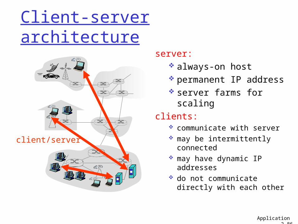
Client-server architecture
server: always-on host permanent IP address server farms for
scalingclients:
communicate with server may be intermittently
connected may have dynamic IP
addresses do not communicate
directly with each other
client/server
Application 2-86
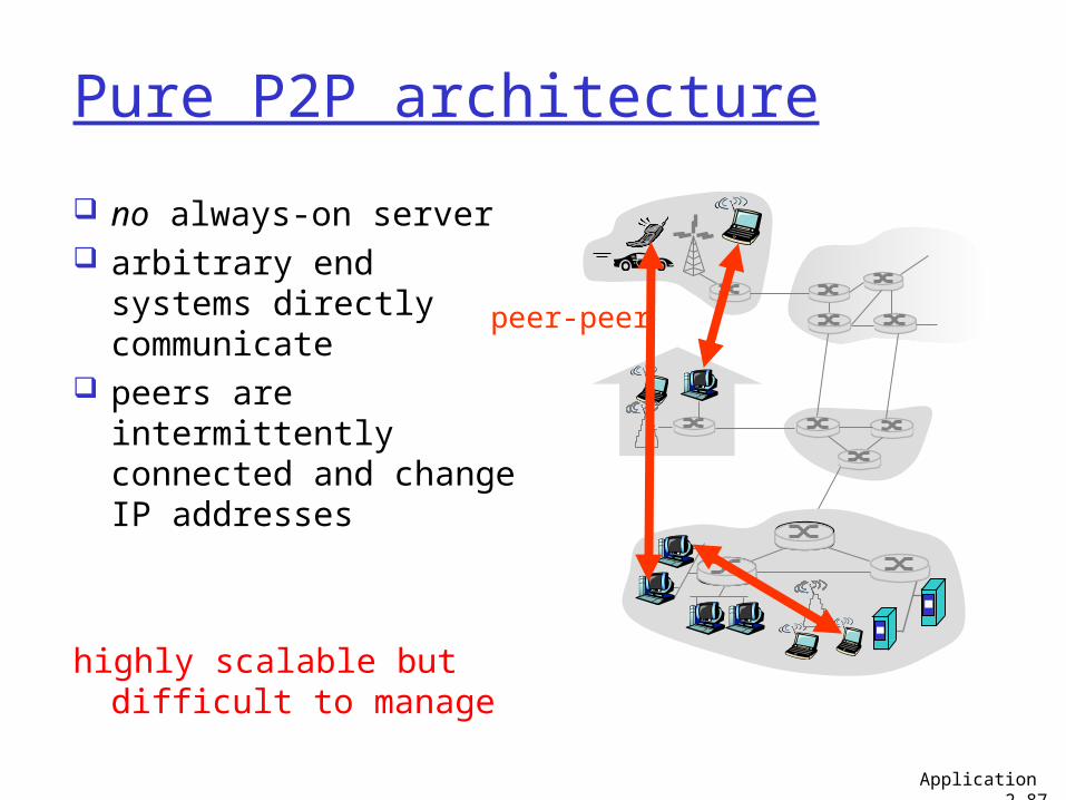
Pure P2P architecture
no always-on server arbitrary end systems
directly communicate peers are
intermittently connected and change IP addresses
highly scalable but difficult to manage
peer-peer
Application 2-87
Hybrid of client-server and P2PSkype
voice-over-IP P2P application centralized server: finding address of
remote party: client-client connection: direct (not through
server) Instant messaging
chatting between two users is P2P centralized service: client presence
detection/location• user registers its IP address with central
server when it comes online• user contacts central server to find IP
addresses of buddies
Application 2-88
Processes communicating
process: program running within a host.
within same host, two processes communicate using inter-process communication (defined by OS).
processes in different hosts communicate by exchanging messages
client process: process that initiates communication
server process: process that waits to be contacted
aside: applications with P2P architectures have client processes & server processes
Application 2-89
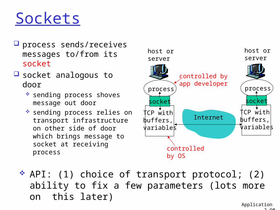
Sockets
process sends/receives messages to/from its socket
socket analogous to door sending process shoves
message out door sending process relies on
transport infrastructure on other side of door which brings message to socket at receiving process
process
TCP withbuffers,variables
socket
host orserver
process
TCP withbuffers,variables
socket
host orserver
Internet
controlledby OS
controlled byapp developer
API: (1) choice of transport protocol; (2) ability to fix a few parameters (lots more on this later)
Application 2-90
Addressing processes to receive messages,
process must have identifier
host device has unique 32-bit IP address
Q: does IP address of host on which process runs suffice for identifying the process?
Application 2-91
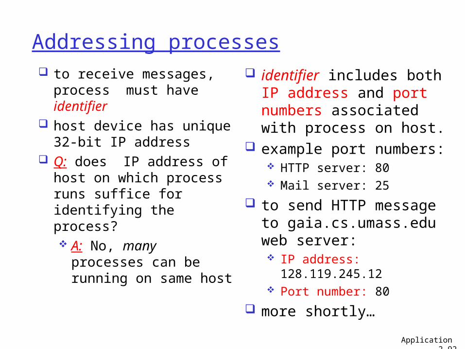
Addressing processes to receive messages,
process must have identifier
host device has unique 32-bit IP address
Q: does IP address of host on which process runs suffice for identifying the process? A: No, many
processes can be running on same host
identifier includes both IP address and port numbers associated with process on host.
example port numbers: HTTP server: 80 Mail server: 25
to send HTTP message to gaia.cs.umass.edu web server: IP address:
128.119.245.12 Port number: 80
more shortly…Application 2-92
App-layer protocol defines
types of messages exchanged, e.g., request, response
message syntax: what fields in messages
& how fields are delineated
message semantics meaning of information
in fields
rules for when and how processes send & respond to messages
public-domain protocols:
defined in RFCs allows for
interoperability e.g., HTTP, SMTPproprietary protocols: e.g., Skype
Application 2-93
What transport service does an app need?
Data loss some apps (e.g., audio)
can tolerate some loss other apps (e.g., file
transfer, telnet) require 100% reliable data transfer
Timing some apps (e.g.,
Internet telephony, interactive games) require low delay to be “effective”
Throughput some apps (e.g.,
multimedia) require minimum amount of throughput to be “effective”
other apps (“elastic apps”) make use of whatever throughput they get
Security encryption, data
integrity, …
Application 2-94
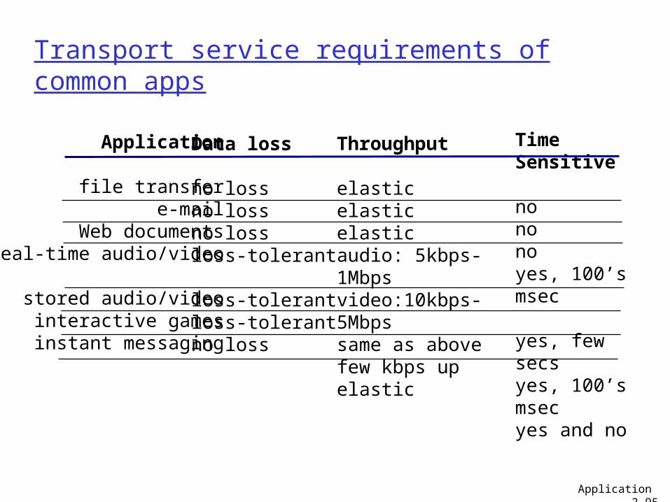
Transport service requirements of common apps
Application
file transfere-mail
Web documentsreal-time audio/video
stored audio/videointeractive gamesinstant messaging
Data loss
no lossno lossno lossloss-tolerant
loss-tolerantloss-tolerantno loss
Throughput
elasticelasticelasticaudio: 5kbps-1Mbpsvideo:10kbps-5Mbpssame as above few kbps upelastic
Time Sensitive
nononoyes, 100’s msec
yes, few secsyes, 100’s msecyes and no
Application 2-95
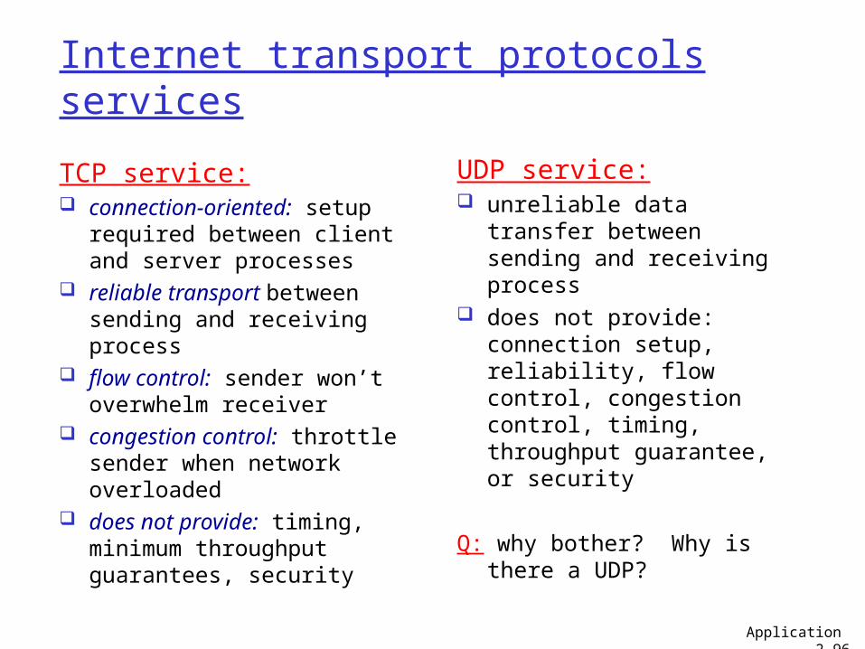
Internet transport protocols services
TCP service: connection-oriented: setup
required between client and server processes
reliable transport between sending and receiving process
flow control: sender won’t overwhelm receiver
congestion control: throttle sender when network overloaded
does not provide: timing, minimum throughput guarantees, security
UDP service: unreliable data transfer
between sending and receiving process
does not provide: connection setup, reliability, flow control, congestion control, timing, throughput guarantee, or security
Q: why bother? Why is there a UDP?
Application 2-96
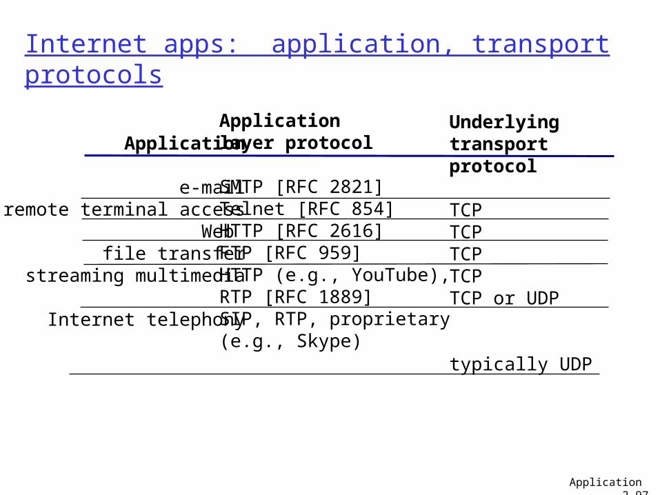
Internet apps: application, transport protocols
Application
e-mailremote terminal access
Web file transfer
streaming multimedia
Internet telephony
Applicationlayer protocol
SMTP [RFC 2821]Telnet [RFC 854]HTTP [RFC 2616]FTP [RFC 959]HTTP (e.g., YouTube), RTP [RFC 1889]SIP, RTP, proprietary(e.g., Skype)
Underlyingtransport protocol
TCPTCPTCPTCPTCP or UDP
typically UDP
Application 2-97
Chapter 2: Application layer
2.1 Principles of network applications app architectures app requirements
2.2 Web and HTTP2.3 FTP2.4 Electronic Mail
SMTP, POP3, IMAP
2.5 DNS
2.6 P2P applications2.7 Socket programming
with TCP2.8 Socket programming
with UDP
Application 2-98
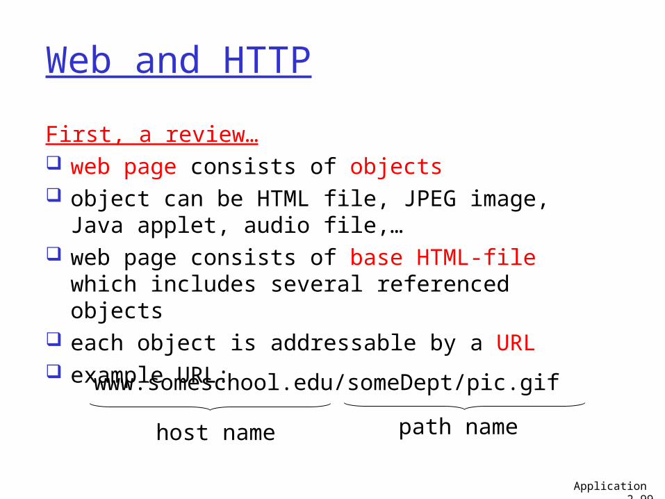
Web and HTTP
First, a review… web page consists of objects object can be HTML file, JPEG image, Java
applet, audio file,… web page consists of base HTML-file which
includes several referenced objects each object is addressable by a URL example URL:
www.someschool.edu/someDept/pic.gif
host name path name
Application 2-99
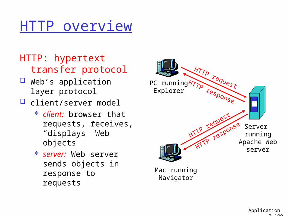
HTTP overview
HTTP: hypertext transfer protocol
Web’s application layer protocol
client/server model client: browser that
requests, receives, “displays” Web objects
server: Web server sends objects in response to requests
PC runningExplorer
Server running
Apache Webserver
Mac runningNavigator
HTTP request
HTTP request
HTTP response
HTTP response
Application 2-100
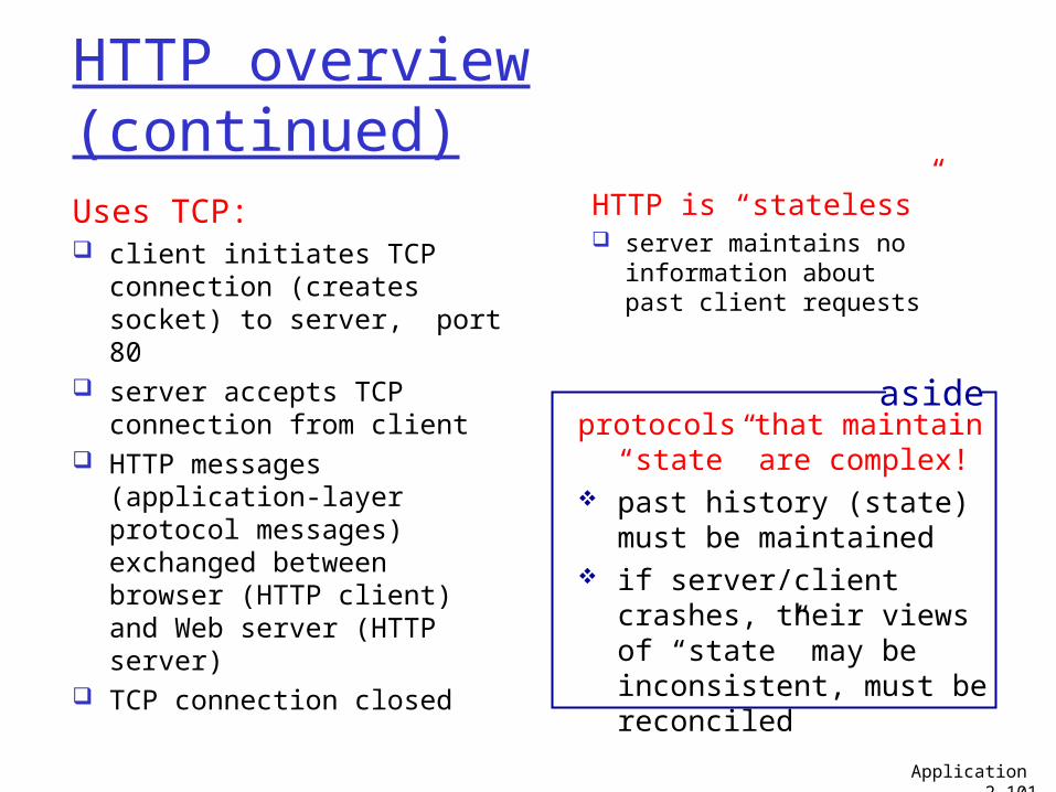
HTTP overview (continued)
Uses TCP: client initiates TCP
connection (creates socket) to server, port 80
server accepts TCP connection from client
HTTP messages (application-layer protocol messages) exchanged between browser (HTTP client) and Web server (HTTP server)
TCP connection closed
HTTP is “stateless” server maintains no
information about past client requests
protocols that maintain “state” are complex!
past history (state) must be maintained
if server/client crashes, their views of “state” may be inconsistent, must be reconciled
aside
Application 2-101
HTTP connections
non-persistent HTTP at most one object
sent over TCP connection.
persistent HTTP multiple objects can
be sent over single TCP connection between client, server.
Application 2-102
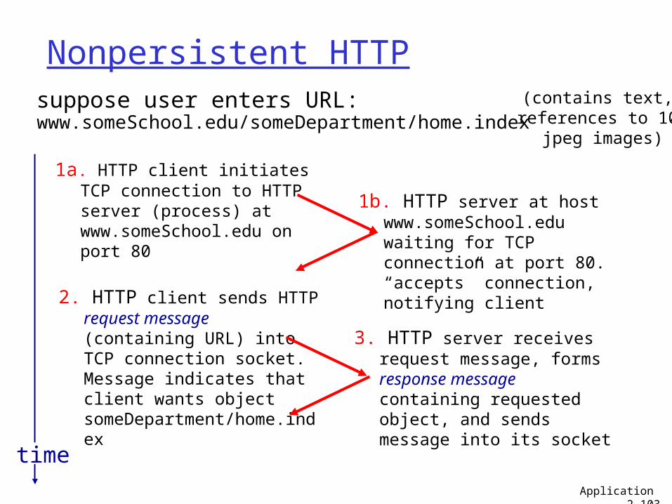
Nonpersistent HTTPsuppose user enters URL:
1a. HTTP client initiates TCP connection to HTTP server (process) at www.someSchool.edu on port 80
2. HTTP client sends HTTP request message (containing URL) into TCP connection socket. Message indicates that client wants object someDepartment/home.index
1b. HTTP server at host www.someSchool.edu waiting for TCP connection at port 80. “accepts” connection, notifying client
3. HTTP server receives request message, forms response message containing requested object, and sends message into its socket
time
(contains text, references to 10
jpeg images)
Application 2-103
www.someSchool.edu/someDepartment/home.index
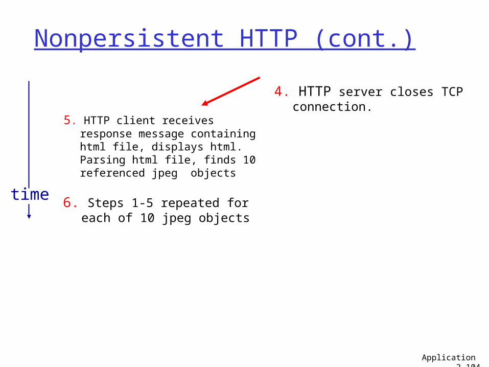
Nonpersistent HTTP (cont.)
5. HTTP client receives response message containing html file, displays html. Parsing html file, finds 10 referenced jpeg objects
6. Steps 1-5 repeated for each of 10 jpeg objects
4. HTTP server closes TCP connection.
time
Application 2-104
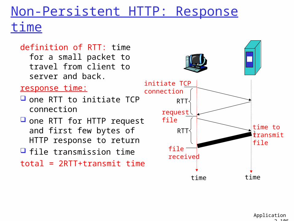
Non-Persistent HTTP: Response time
definition of RTT: time for a small packet to travel from client to server and back.
response time: one RTT to initiate TCP
connection one RTT for HTTP request
and first few bytes of HTTP response to return
file transmission timetotal = 2RTT+transmit time
time to transmit file
initiate TCPconnection
RTT
requestfile
RTT
filereceived
time time
Application 2-105
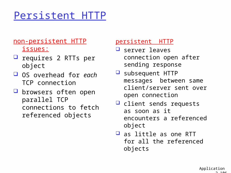
Persistent HTTP
non-persistent HTTP issues: requires 2 RTTs per object OS overhead for each TCP
connection browsers often open
parallel TCP connections to fetch referenced objects
persistent HTTP server leaves connection
open after sending response
subsequent HTTP messages between same client/server sent over open connection
client sends requests as soon as it encounters a referenced object
as little as one RTT for all the referenced objects
Application 2-106
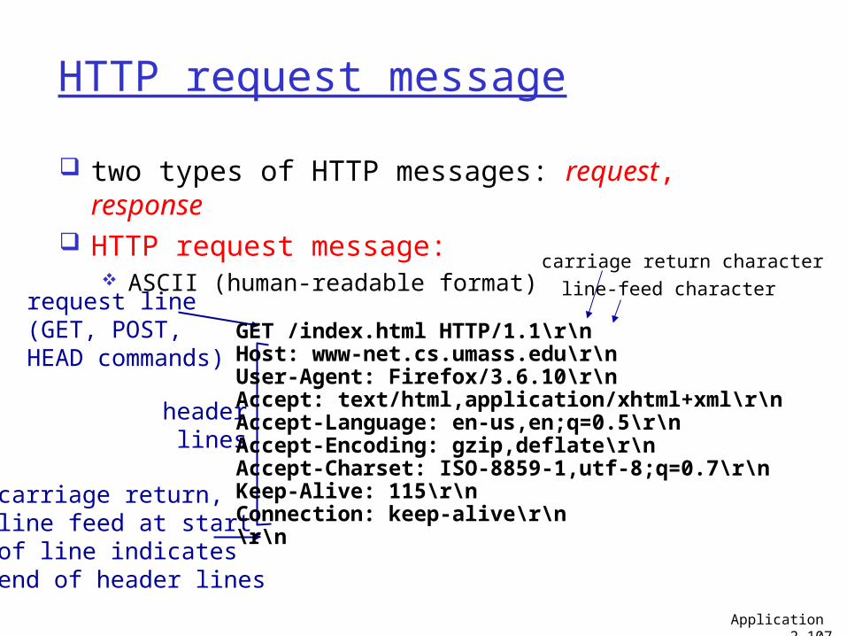
HTTP request message
two types of HTTP messages: request, response
HTTP request message: ASCII (human-readable format)
request line(GET, POST, HEAD commands)
header lines
carriage return, line feed at startof line indicatesend of header lines
Application 2-107
GET /index.html HTTP/1.1\r\nHost: www-net.cs.umass.edu\r\nUser-Agent: Firefox/3.6.10\r\nAccept: text/html,application/xhtml+xml\r\nAccept-Language: en-us,en;q=0.5\r\nAccept-Encoding: gzip,deflate\r\nAccept-Charset: ISO-8859-1,utf-8;q=0.7\r\nKeep-Alive: 115\r\nConnection: keep-alive\r\n\r\n
carriage return character
line-feed character
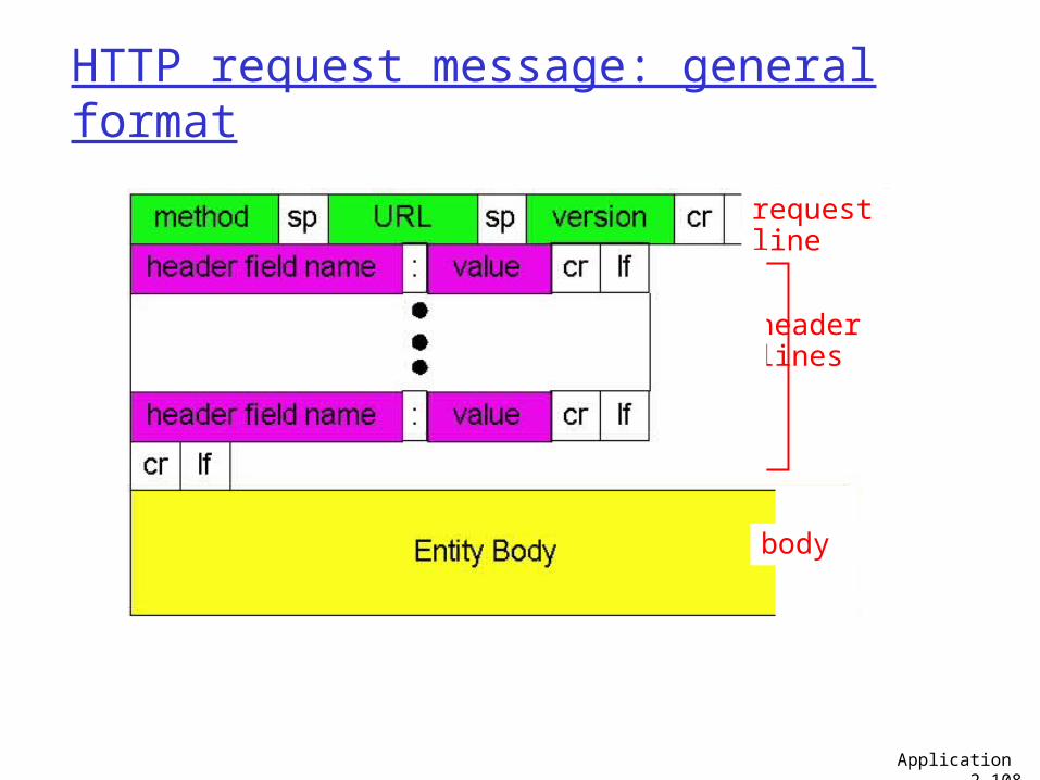
HTTP request message: general format
Application 2-108
requestline
headerlines
body
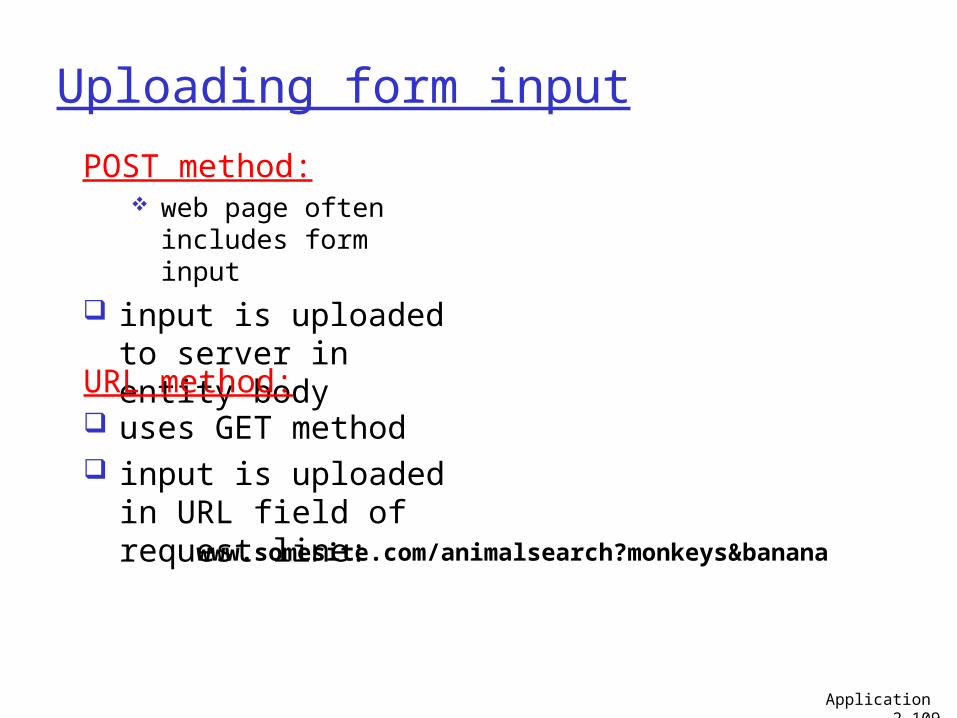
Uploading form input
POST method: web page often
includes form input
input is uploaded to server in entity body
URL method: uses GET method input is uploaded in
URL field of request line: www.somesite.com/animalsearch?monkeys&banana
Application 2-109
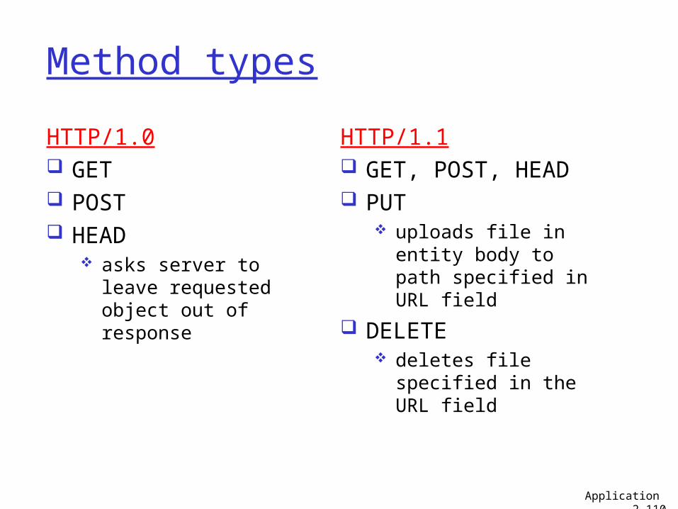
Method types
HTTP/1.0 GET POST HEAD
asks server to leave requested object out of response
HTTP/1.1 GET, POST, HEAD PUT
uploads file in entity body to path specified in URL field
DELETE deletes file specified
in the URL field
Application 2-110
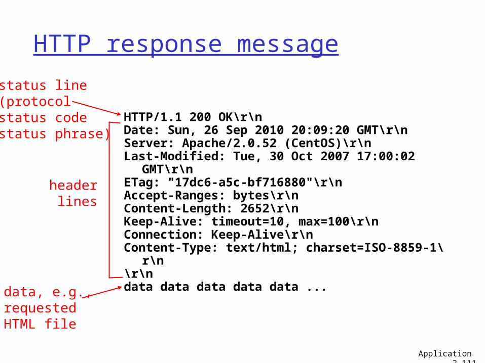
HTTP response message
status line(protocolstatus codestatus phrase)
header lines
data, e.g., requestedHTML file
Application 2-111
HTTP/1.1 200 OK\r\nDate: Sun, 26 Sep 2010 20:09:20 GMT\r\nServer: Apache/2.0.52 (CentOS)\r\nLast-Modified: Tue, 30 Oct 2007 17:00:02
GMT\r\nETag: "17dc6-a5c-bf716880"\r\nAccept-Ranges: bytes\r\nContent-Length: 2652\r\nKeep-Alive: timeout=10, max=100\r\nConnection: Keep-Alive\r\nContent-Type: text/html; charset=ISO-8859-1\
r\n\r\ndata data data data data ...
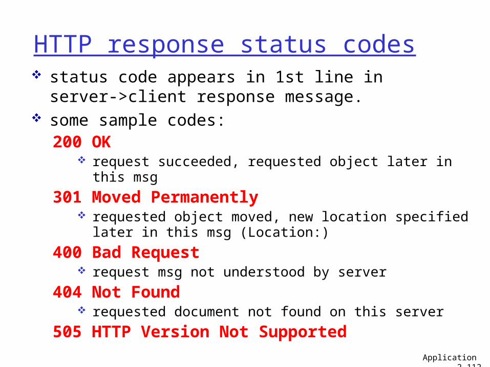
HTTP response status codes
200 OK request succeeded, requested object later in this msg
301 Moved Permanently requested object moved, new location specified later in
this msg (Location:)
400 Bad Request request msg not understood by server
404 Not Found requested document not found on this server
505 HTTP Version Not Supported
status code appears in 1st line in server->client response message.
some sample codes:
Application 2-112
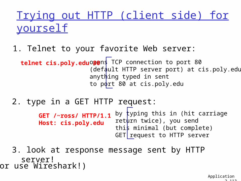
Trying out HTTP (client side) for yourself
1. Telnet to your favorite Web server:
opens TCP connection to port 80(default HTTP server port) at cis.poly.edu.anything typed in sent to port 80 at cis.poly.edu
telnet cis.poly.edu 80
2. type in a GET HTTP request:
GET /~ross/ HTTP/1.1Host: cis.poly.edu
by typing this in (hit carriagereturn twice), you sendthis minimal (but complete) GET request to HTTP server
3. look at response message sent by HTTP server!
Application 2-113
(or use Wireshark!)
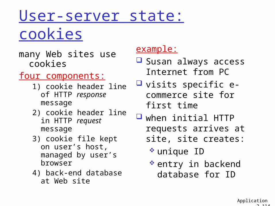
User-server state: cookies
many Web sites use cookies
four components:1) cookie header line of
HTTP response message
2) cookie header line in HTTP request message
3) cookie file kept on user’s host, managed by user’s browser
4) back-end database at Web site
example: Susan always access
Internet from PC visits specific e-
commerce site for first time
when initial HTTP requests arrives at site, site creates: unique ID entry in backend
database for ID
Application 2-114
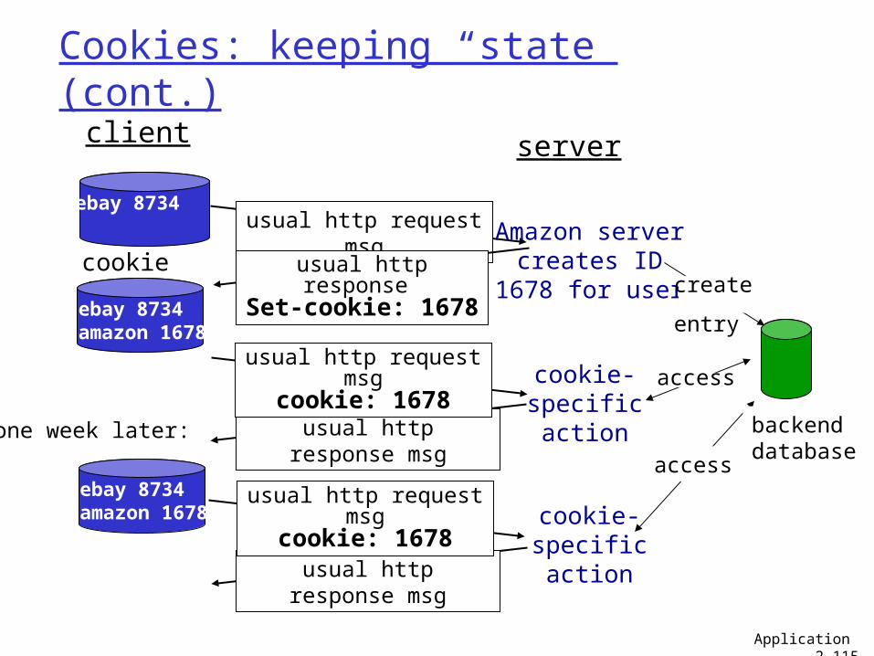
Cookies: keeping “state” (cont.)
client server
usual http response msg
usual http response msg
cookie file
one week later:
usual http request msg
cookie: 1678cookie-specificaction
access
ebay 8734usual http request
msgAmazon server
creates ID1678 for usercreate
entry
usual http response Set-cookie: 1678
ebay 8734amazon 1678
usual http request msg
cookie: 1678cookie-specificaction
accessebay 8734amazon 1678
backenddatabase
Application 2-115
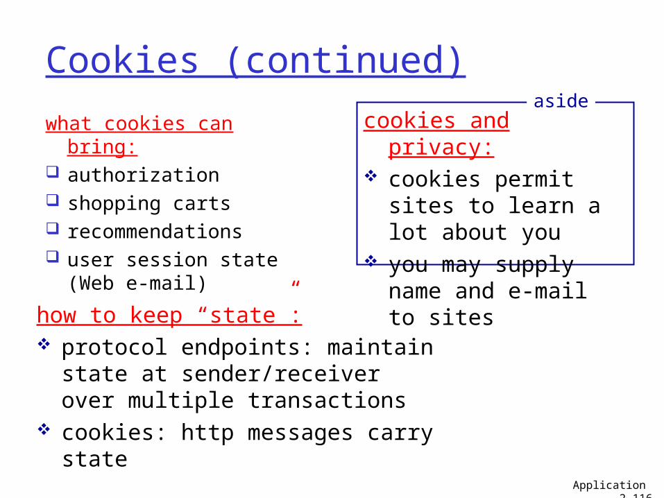
Cookies (continued)
what cookies can bring: authorization shopping carts recommendations user session state
(Web e-mail)
cookies and privacy: cookies permit sites
to learn a lot about you
you may supply name and e-mail to sites
aside
how to keep “state”: protocol endpoints: maintain
state at sender/receiver over multiple transactions
cookies: http messages carry state
Application 2-116
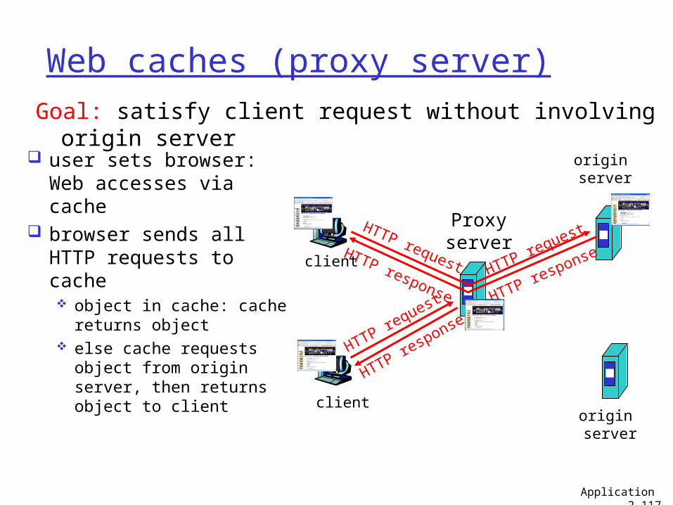
Web caches (proxy server)
user sets browser: Web accesses via cache
browser sends all HTTP requests to cache object in cache: cache
returns object else cache requests
object from origin server, then returns object to client
Goal: satisfy client request without involving origin server
client
Proxyserver
client
HTTP request
HTTP response
HTTP request HTTP request
origin server
origin server
HTTP response HTTP response
Application 2-117
More about Web caching
cache acts as both client and server
typically cache is installed by ISP (university, company, residential ISP)
why Web caching? reduce response time
for client request reduce traffic on an
institution’s access link.
Internet dense with caches: enables “poor” content providers to effectively deliver content (but so does P2P file sharing)
Application 2-118
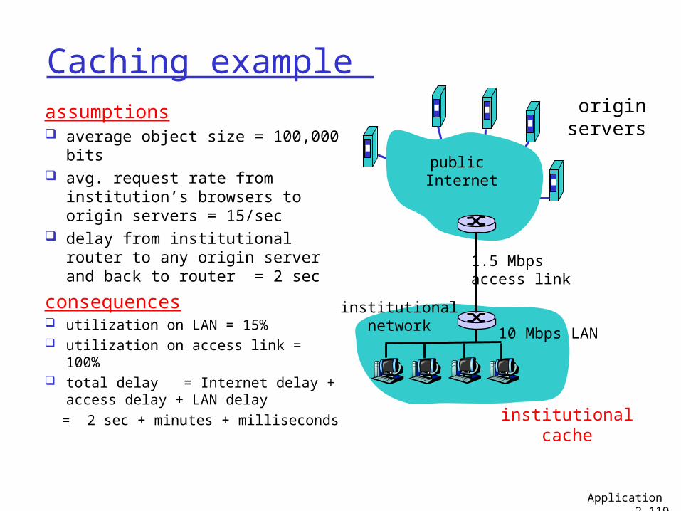
Caching example assumptions average object size = 100,000
bits avg. request rate from
institution’s browsers to origin servers = 15/sec
delay from institutional router to any origin server and back to router = 2 sec
consequences utilization on LAN = 15% utilization on access link = 100% total delay = Internet delay +
access delay + LAN delay = 2 sec + minutes + milliseconds
originservers
public Internet
institutionalnetwork 10 Mbps LAN
1.5 Mbps access link
institutionalcache
Application 2-119
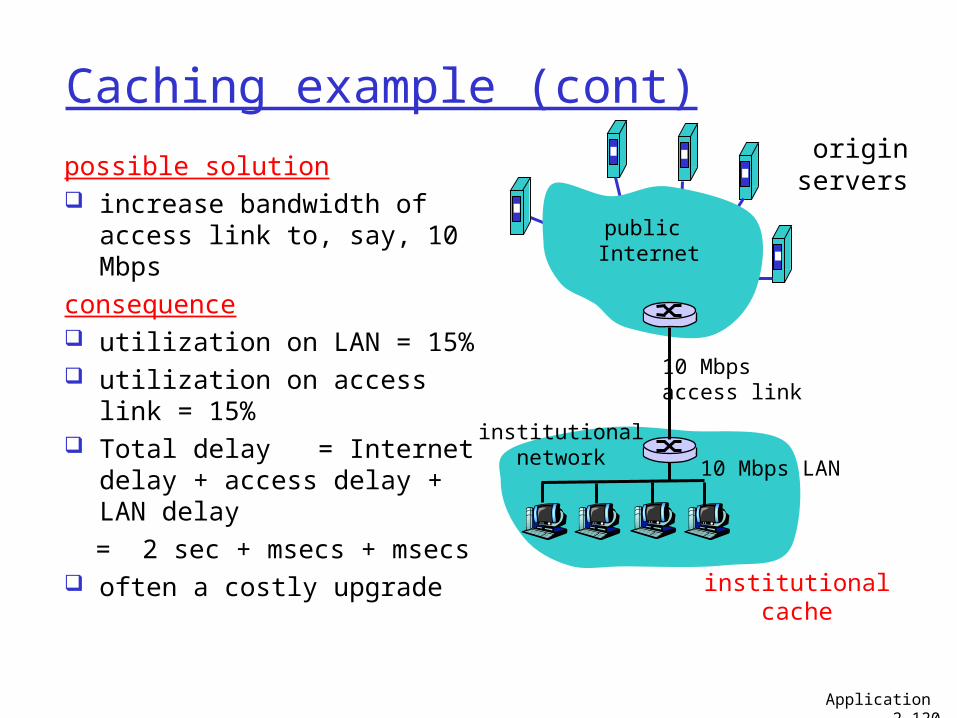
Caching example (cont)
possible solution increase bandwidth of
access link to, say, 10 Mbpsconsequence utilization on LAN = 15% utilization on access link =
15% Total delay = Internet
delay + access delay + LAN delay
= 2 sec + msecs + msecs often a costly upgrade
originservers
public Internet
institutionalnetwork 10 Mbps LAN
10 Mbps access link
institutionalcache
Application 2-120
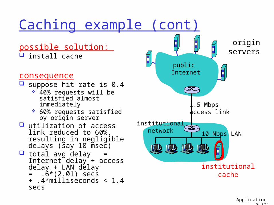
Caching example (cont)
possible solution: install cache
consequence suppose hit rate is 0.4
40% requests will be satisfied almost immediately
60% requests satisfied by origin server
utilization of access link reduced to 60%, resulting in negligible delays (say 10 msec)
total avg delay = Internet delay + access delay + LAN delay = .6*(2.01) secs + .4*milliseconds < 1.4 secs
originservers
public Internet
institutionalnetwork 10 Mbps LAN
1.5 Mbps access link
institutionalcache
Application 2-121
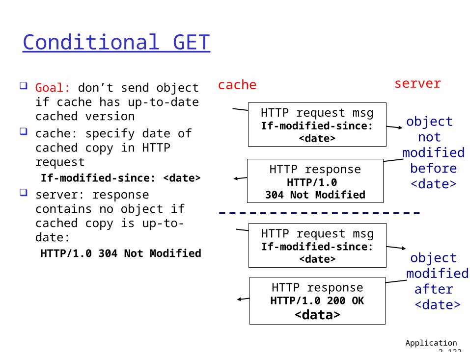
Conditional GET
Goal: don’t send object if cache has up-to-date cached version
cache: specify date of cached copy in HTTP requestIf-modified-since:
<date> server: response contains
no object if cached copy is up-to-date: HTTP/1.0 304 Not
Modified
cache server
HTTP request msgIf-modified-since: <date>
HTTP responseHTTP/1.0
304 Not Modified
object not
modifiedbefore<date>
HTTP request msgIf-modified-since: <date>
HTTP responseHTTP/1.0 200 OK
<data>
object modified
after <date>
Application 2-122
Chapter 2: Application layer
2.1 Principles of network applications
2.2 Web and HTTP2.3 FTP 2.4 Electronic mail
SMTP, POP3, IMAP
2.5 DNS
2.6 P2P applications2.7 Socket programming
with TCP2.8 Socket programming
with UDP
Application 2-123
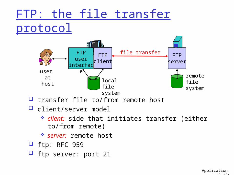
FTP: the file transfer protocol
transfer file to/from remote host client/server model
client: side that initiates transfer (either to/from remote)
server: remote host ftp: RFC 959 ftp server: port 21
file transfer FTPserver
FTPuser
interface
FTPclient
local filesystem
remote filesystem
user at host
Application 2-124
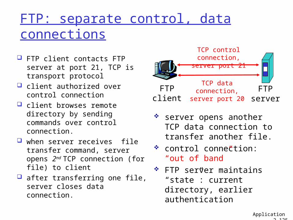
FTP: separate control, data connections
FTP client contacts FTP server at port 21, TCP is transport protocol
client authorized over control connection
client browses remote directory by sending commands over control connection.
when server receives file transfer command, server opens 2nd TCP connection (for file) to client
after transferring one file, server closes data connection.
FTPclient
FTPserver
TCP control connection,
server port 21
TCP data connection,server port 20
server opens another TCP data connection to transfer another file.
control connection: “out of band”
FTP server maintains “state”: current directory, earlier authentication
Application 2-125
FTP commands, responses
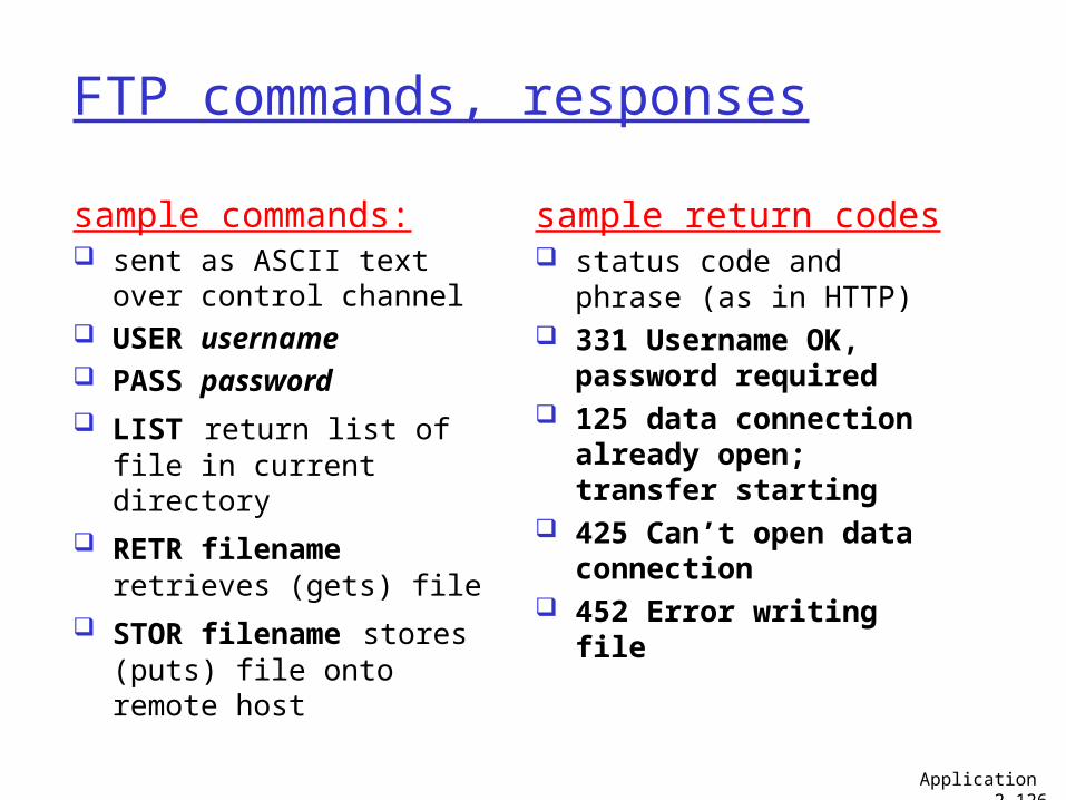
sample commands: sent as ASCII text over
control channel USER username PASS password LIST return list of file in
current directory RETR filename retrieves
(gets) file STOR filename stores
(puts) file onto remote host
sample return codes status code and phrase
(as in HTTP) 331 Username OK,
password required 125 data connection
already open; transfer starting
425 Can’t open data connection
452 Error writing file
Application 2-126
Chapter 2: Application layer
2.1 Principles of network applications
2.2 Web and HTTP2.3 FTP 2.4 Electronic Mail
SMTP, POP3, IMAP
2.5 DNS
2.6 P2P applications2.7 Socket programming
with TCP2.8 Socket programming
with UDP
Application 2-127
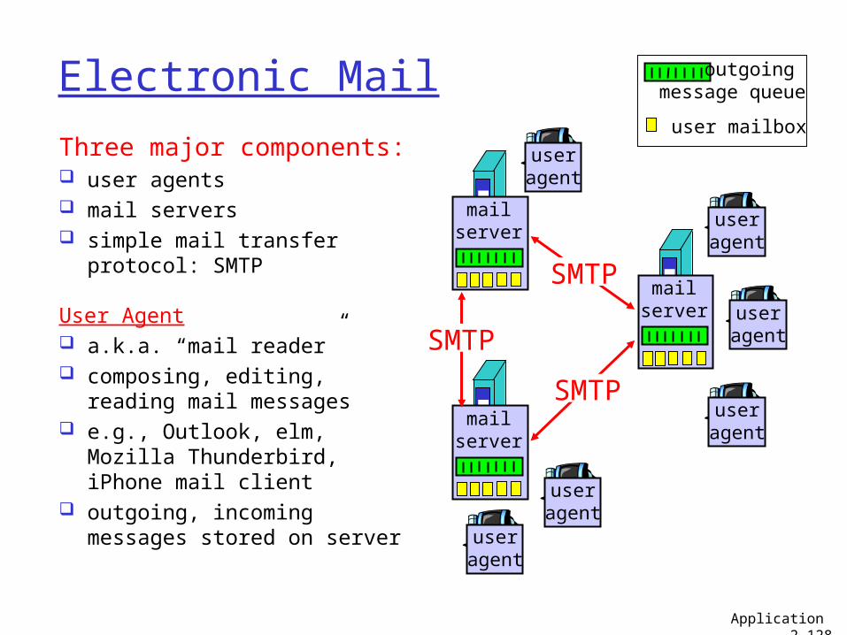
Electronic Mail
Three major components: user agents mail servers simple mail transfer protocol:
SMTP
User Agent a.k.a. “mail reader” composing, editing, reading
mail messages e.g., Outlook, elm, Mozilla
Thunderbird, iPhone mail client
outgoing, incoming messages stored on server
user mailbox
outgoing message queue
mailserver
useragent
useragent
useragent
mailserver
useragent
useragent
mailserver
useragent
SMTP
SMTP
SMTP
Application 2-128
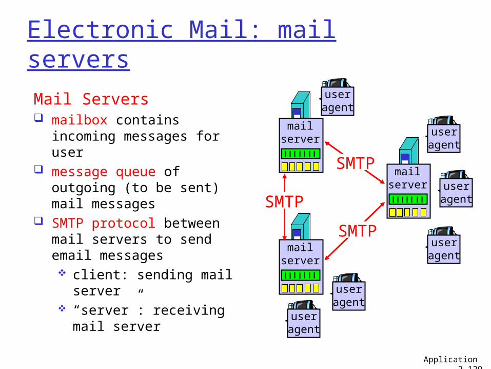
Electronic Mail: mail servers
Mail Servers mailbox contains
incoming messages for user
message queue of outgoing (to be sent) mail messages
SMTP protocol between mail servers to send email messages client: sending mail
server “server”: receiving
mail server
mailserver
useragent
useragent
useragent
mailserver
useragent
useragent
mailserver
useragent
SMTP
SMTP
SMTP
Application 2-129
Electronic Mail: SMTP [RFC 2821]
uses TCP to reliably transfer email message from client to server, port 25
direct transfer: sending server to receiving server three phases of transfer
handshaking (greeting) transfer of messages closure
command/response interaction commands: ASCII text response: status code and phrase
messages must be in 7-bit ASCII
Application 2-130
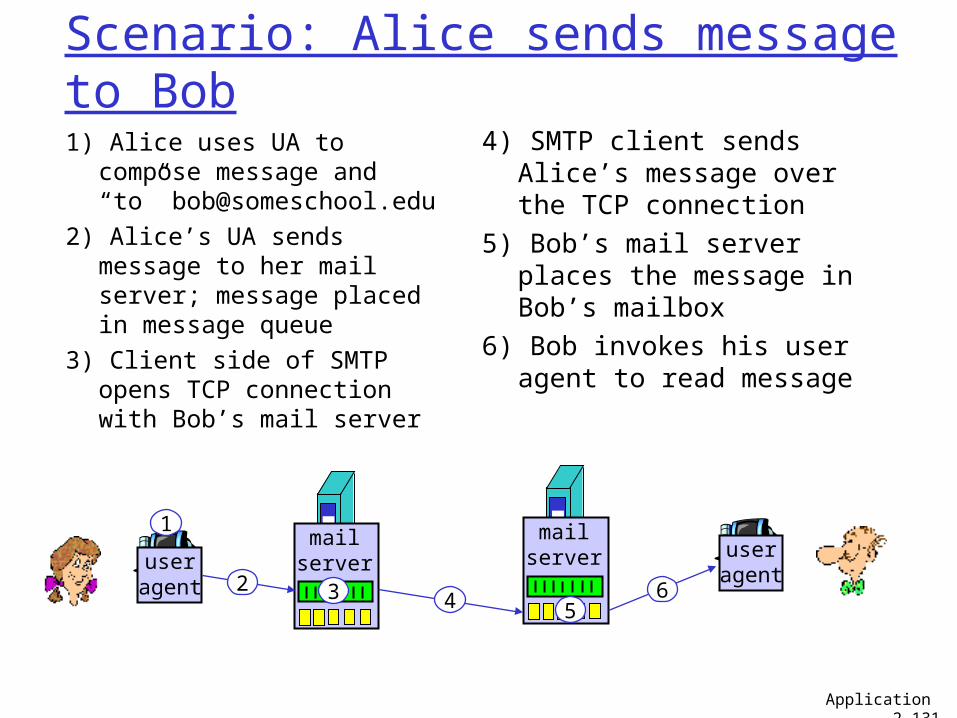
Scenario: Alice sends message to Bob1) Alice uses UA to compose
message and “to” [email protected]
2) Alice’s UA sends message to her mail server; message placed in message queue
3) Client side of SMTP opens TCP connection with Bob’s mail server
4) SMTP client sends Alice’s message over the TCP connection
5) Bob’s mail server places the message in Bob’s mailbox
6) Bob invokes his user agent to read message
useragent
mailserver
mailserver user
agent
1
2 3 4 56
Application 2-131
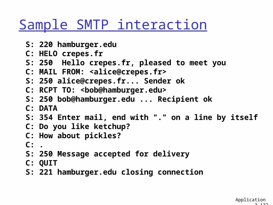
Sample SMTP interaction S: 220 hamburger.edu C: HELO crepes.fr S: 250 Hello crepes.fr, pleased to meet you C: MAIL FROM: <[email protected]> S: 250 [email protected]... Sender ok C: RCPT TO: <[email protected]> S: 250 [email protected] ... Recipient ok C: DATA S: 354 Enter mail, end with "." on a line by itself C: Do you like ketchup? C: How about pickles? C: . S: 250 Message accepted for delivery C: QUIT S: 221 hamburger.edu closing connection
Application 2-132
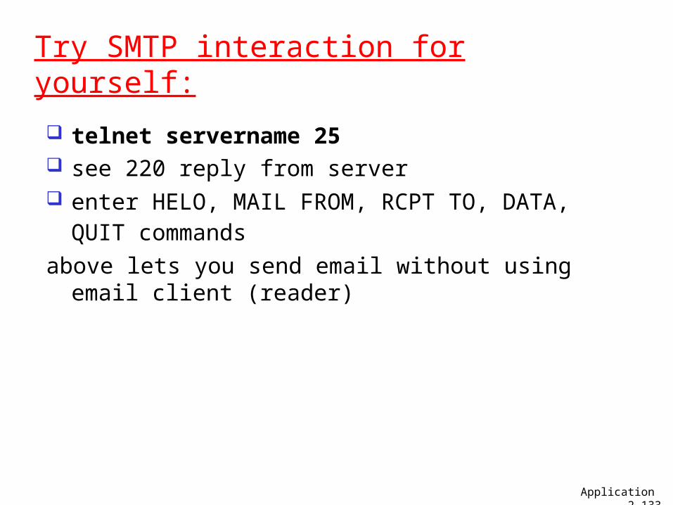
Try SMTP interaction for yourself:
telnet servername 25 see 220 reply from server enter HELO, MAIL FROM, RCPT TO, DATA, QUIT
commands above lets you send email without using email
client (reader)
Application 2-133
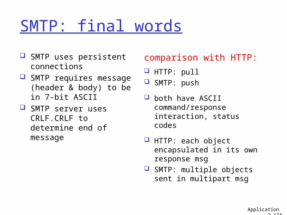
SMTP: final words
SMTP uses persistent connections
SMTP requires message (header & body) to be in 7-bit ASCII
SMTP server uses CRLF.CRLF to determine end of message
comparison with HTTP: HTTP: pull SMTP: push
both have ASCII command/response interaction, status codes
HTTP: each object encapsulated in its own response msg
SMTP: multiple objects sent in multipart msg
Application 2-134
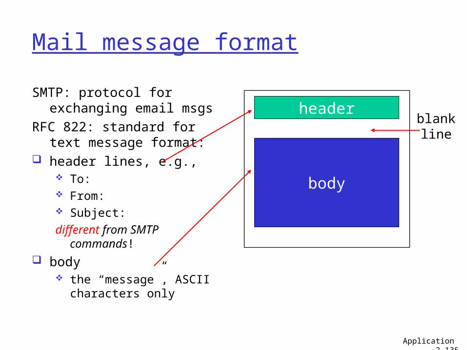
Mail message format
SMTP: protocol for exchanging email msgs
RFC 822: standard for text message format:
header lines, e.g., To: From: Subject:different from SMTP
commands! body
the “message”, ASCII characters only
header
body
blankline
Application 2-135
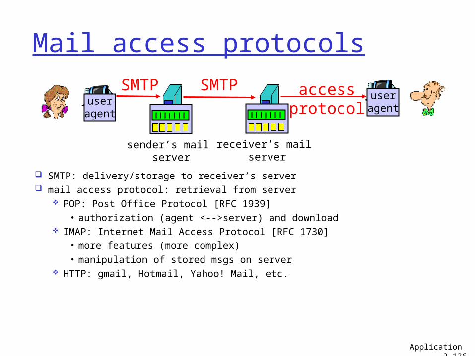
Mail access protocols
SMTP: delivery/storage to receiver’s server mail access protocol: retrieval from server
POP: Post Office Protocol [RFC 1939]• authorization (agent <-->server) and download
IMAP: Internet Mail Access Protocol [RFC 1730]• more features (more complex)• manipulation of stored msgs on server
HTTP: gmail, Hotmail, Yahoo! Mail, etc.
useragent
sender’s mail server
useragent
SMTP SMTP accessprotocol
receiver’s mail server
Application 2-136
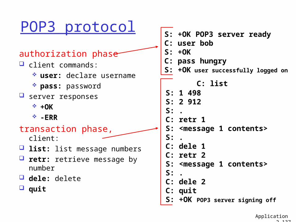
POP3 protocol
authorization phase client commands:
user: declare username pass: password
server responses +OK -ERR
transaction phase, client: list: list message numbers retr: retrieve message by
number dele: delete quit
C: list S: 1 498 S: 2 912 S: . C: retr 1 S: <message 1 contents> S: . C: dele 1 C: retr 2 S: <message 1 contents> S: . C: dele 2 C: quit S: +OK POP3 server signing off
S: +OK POP3 server ready C: user bob S: +OK C: pass hungry S: +OK user successfully logged on
Application 2-137
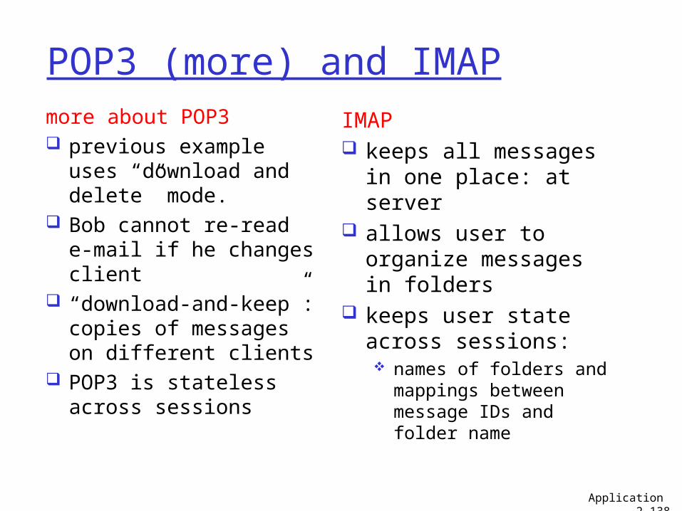
POP3 (more) and IMAPmore about POP3 previous example
uses “download and delete” mode.
Bob cannot re-read e-mail if he changes client
“download-and-keep”: copies of messages on different clients
POP3 is stateless across sessions
IMAP keeps all messages in
one place: at server allows user to
organize messages in folders
keeps user state across sessions: names of folders and
mappings between message IDs and folder name
Application 2-138
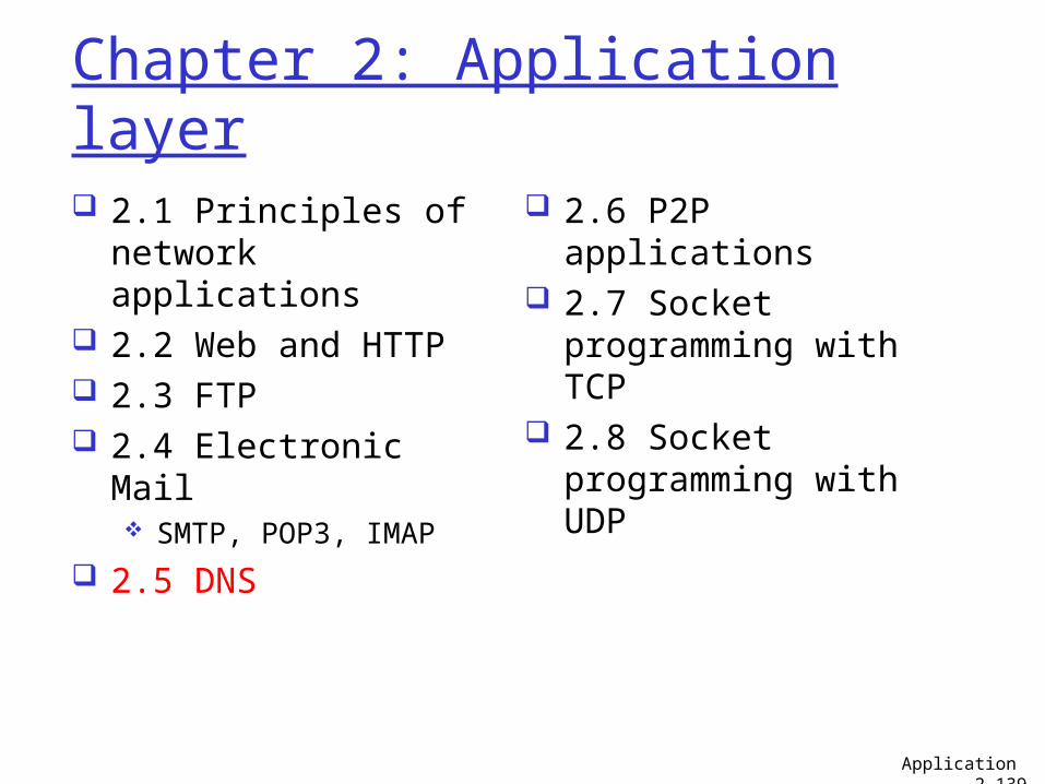
Chapter 2: Application layer
2.1 Principles of network applications
2.2 Web and HTTP 2.3 FTP 2.4 Electronic Mail
SMTP, POP3, IMAP
2.5 DNS
2.6 P2P applications 2.7 Socket
programming with TCP 2.8 Socket
programming with UDP
Application 2-139
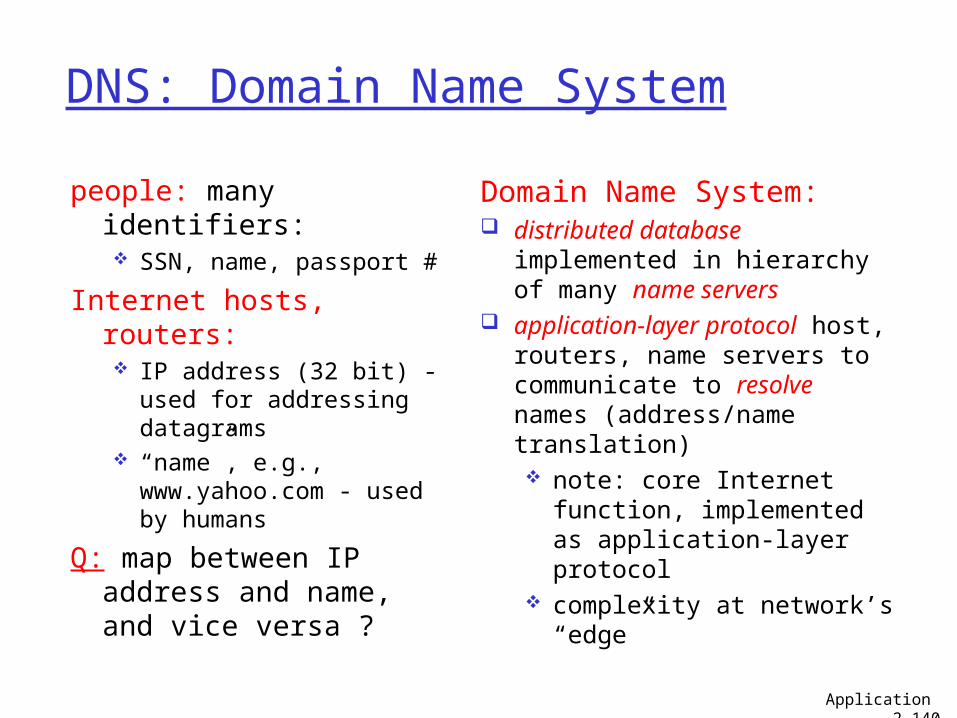
DNS: Domain Name System
people: many identifiers: SSN, name, passport #
Internet hosts, routers: IP address (32 bit) -
used for addressing datagrams
“name”, e.g., www.yahoo.com - used by humans
Q: map between IP address and name, and vice versa ?
Domain Name System: distributed database
implemented in hierarchy of many name servers
application-layer protocol host, routers, name servers to communicate to resolve names (address/name translation) note: core Internet
function, implemented as application-layer protocol
complexity at network’s “edge”
Application 2-140
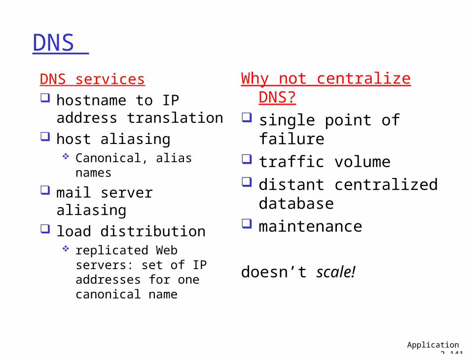
DNS Why not centralize DNS? single point of failure traffic volume distant centralized
database maintenance
doesn’t scale!
DNS services hostname to IP
address translation host aliasing
Canonical, alias names
mail server aliasing load distribution
replicated Web servers: set of IP addresses for one canonical name
Application 2-141
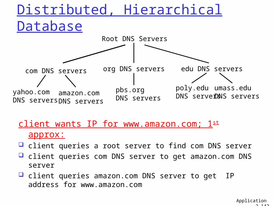
Root DNS Servers
com DNS servers org DNS servers edu DNS servers
poly.eduDNS servers
umass.eduDNS servers
yahoo.comDNS servers
amazon.comDNS servers
pbs.orgDNS servers
Distributed, Hierarchical Database
client wants IP for www.amazon.com; 1st approx: client queries a root server to find com DNS server client queries com DNS server to get amazon.com DNS
server client queries amazon.com DNS server to get IP address
for www.amazon.com
Application 2-142
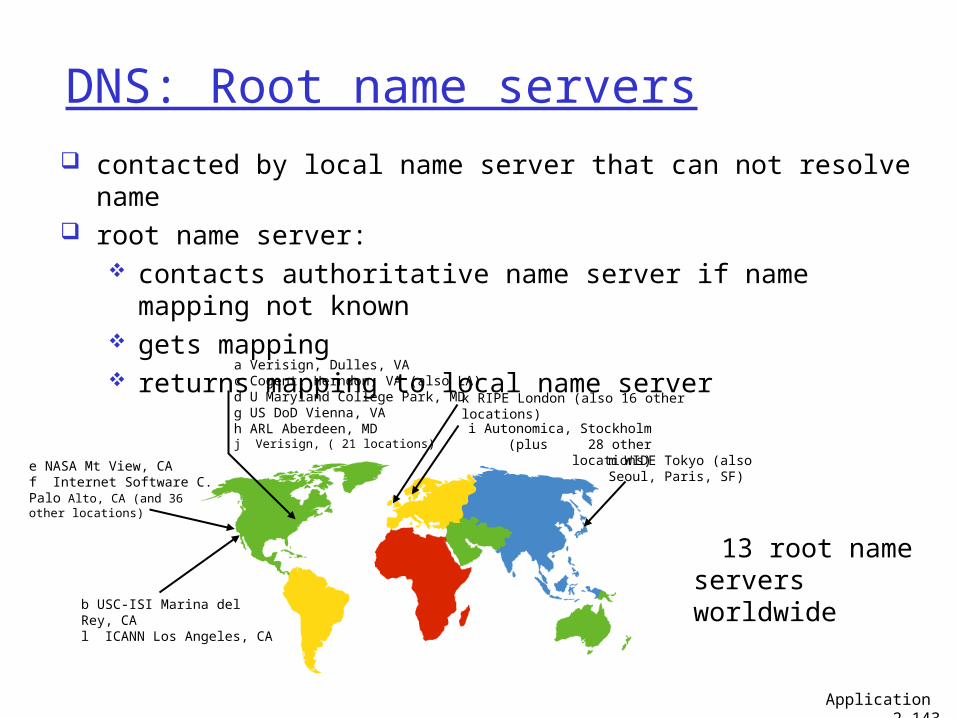
DNS: Root name servers contacted by local name server that can not resolve name root name server:
contacts authoritative name server if name mapping not known
gets mapping returns mapping to local name server
13 root name servers worldwideb USC-ISI Marina del Rey, CA
l ICANN Los Angeles, CA
e NASA Mt View, CAf Internet Software C. Palo Alto, CA (and 36 other locations)
i Autonomica, Stockholm (plus 28 other locations)
k RIPE London (also 16 other locations)
m WIDE Tokyo (also Seoul, Paris, SF)
a Verisign, Dulles, VAc Cogent, Herndon, VA (also LA)d U Maryland College Park, MDg US DoD Vienna, VAh ARL Aberdeen, MDj Verisign, ( 21 locations)
Application 2-143
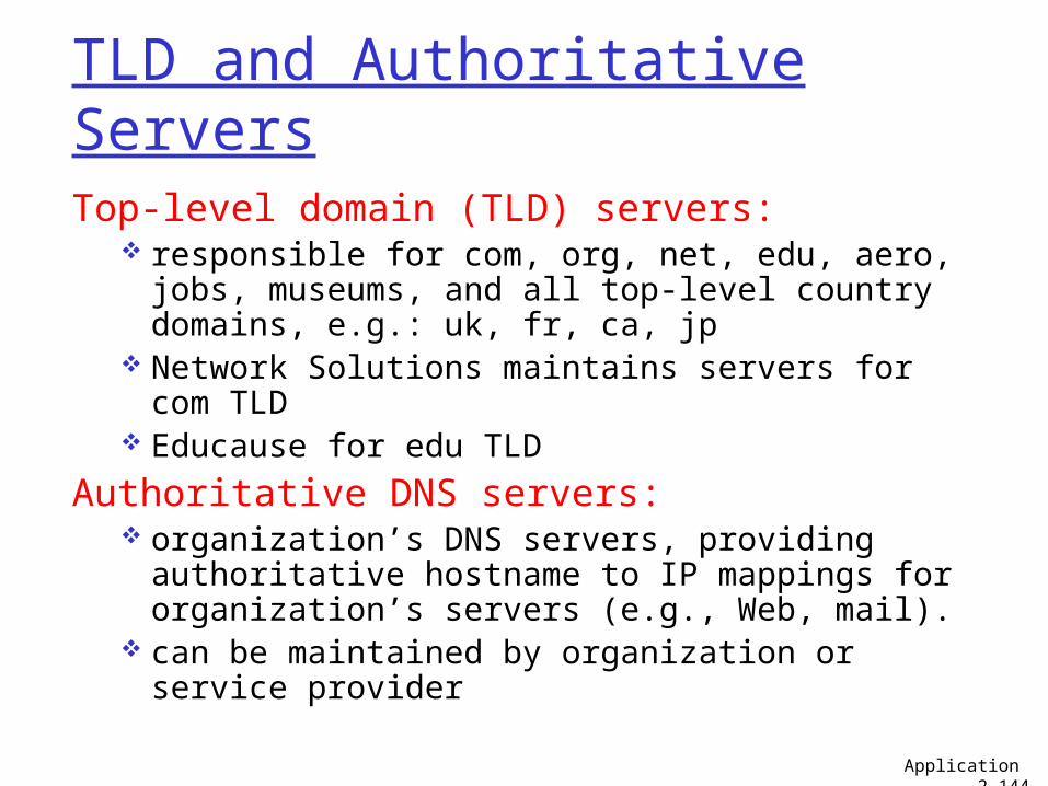
TLD and Authoritative ServersTop-level domain (TLD) servers:
responsible for com, org, net, edu, aero, jobs, museums, and all top-level country domains, e.g.: uk, fr, ca, jp
Network Solutions maintains servers for com TLD
Educause for edu TLD
Authoritative DNS servers: organization’s DNS servers, providing
authoritative hostname to IP mappings for organization’s servers (e.g., Web, mail).
can be maintained by organization or service provider
Application 2-144
Local Name Server
does not strictly belong to hierarchy each ISP (residential ISP, company,
university) has one also called “default name server”
when host makes DNS query, query is sent to its local DNS server acts as proxy, forwards query into hierarchy
Application 2-145
requesting hostcis.poly.edu
gaia.cs.umass.edu
root DNS server
local DNS serverdns.poly.edu
1
23
4
5
6
authoritative DNS serverdns.cs.umass.edu
78
TLD DNS server
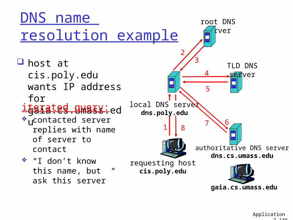
DNS name resolution example
host at cis.poly.edu wants IP address for gaia.cs.umass.edu
iterated query: contacted server
replies with name of server to contact
“I don’t know this name, but ask this server”
Application 2-146
requesting hostcis.poly.edu
gaia.cs.umass.edu
root DNS server
local DNS serverdns.poly.edu
1
2
45
6
authoritative DNS serverdns.cs.umass.edu
7
8
TLD DNS server
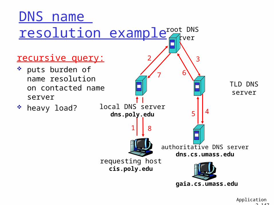
3recursive query: puts burden of
name resolution on contacted name server
heavy load?
DNS name resolution example
Application 2-147
DNS: caching and updating records once (any) name server learns mapping, it
caches mapping cache entries timeout (disappear) after
some time TLD servers typically cached in local name
servers• Thus root name servers not often visited
update/notify mechanisms proposed IETF standard RFC 2136
Application 2-148
DNS records
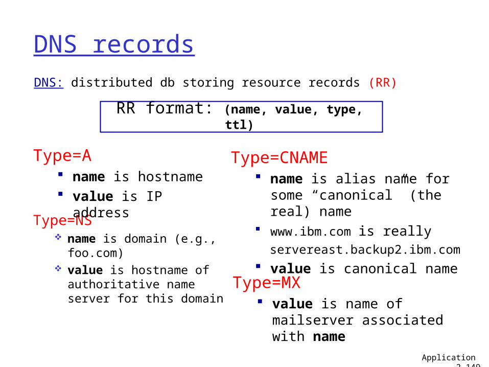
DNS: distributed db storing resource records (RR)
Type=NS name is domain (e.g.,
foo.com) value is hostname of
authoritative name server for this domain
RR format: (name, value, type, ttl)
Type=A name is hostname value is IP address
Type=CNAME name is alias name for some
“canonical” (the real) name www.ibm.com is really servereast.backup2.ibm.com value is canonical name
Type=MX value is name of
mailserver associated with name
Application 2-149
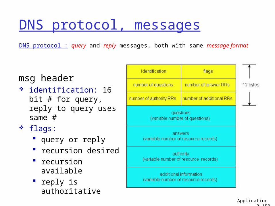
DNS protocol, messagesDNS protocol : query and reply messages, both with same message format
msg header identification: 16 bit #
for query, reply to query uses same #
flags: query or reply recursion desired recursion available reply is authoritative
Application 2-150
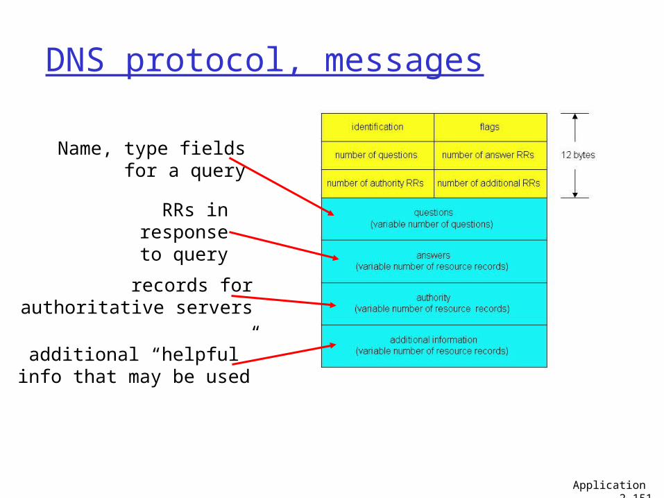
DNS protocol, messages
Name, type fields for a query
RRs in responseto query
records forauthoritative servers
additional “helpful”info that may be used
Application 2-151
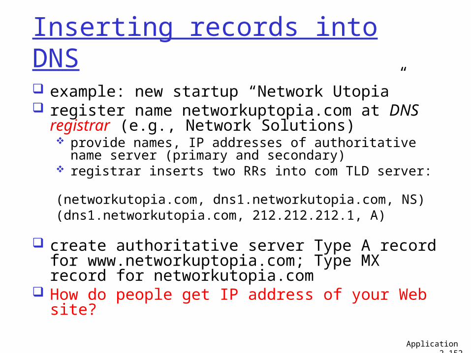
Inserting records into DNS
example: new startup “Network Utopia” register name networkuptopia.com at DNS
registrar (e.g., Network Solutions) provide names, IP addresses of authoritative name
server (primary and secondary) registrar inserts two RRs into com TLD server:
(networkutopia.com, dns1.networkutopia.com, NS)(dns1.networkutopia.com, 212.212.212.1, A)
create authoritative server Type A record for www.networkuptopia.com; Type MX record for networkutopia.com
How do people get IP address of your Web site?
Application 2-152
Chapter 2: Application layer
2.1 Principles of network applications
2.2 Web and HTTP2.3 FTP2.4 Electronic Mail
SMTP, POP3, IMAP
2.5 DNS
2.6 P2P applications2.7 Socket programming
with TCP2.8 Socket programming
with UDP
Application 2-153
Future Client Server Nets: Beyond IP Networking
Building Large Networks (at the edge)… Large Scale Ethernets and enterprise
networks - Scaling Ethernets to millions of nodes
Building networks for the backend of the Internet – networks for cloud computing and data centers
154
Slides in this section by Prof. Zhi-Li Zhang, UMN Advanced Networking Course CSci5221
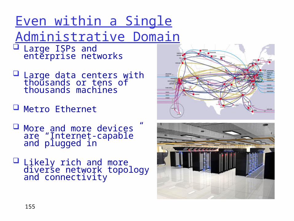
Even within a Single Administrative Domain Large ISPs and enterprise
networks
Large data centers with thousands or tens of thousands machines
Metro Ethernet
More and more devices are “Internet-capable” and plugged in
Likely rich and more diverse network topology and connectivity
155
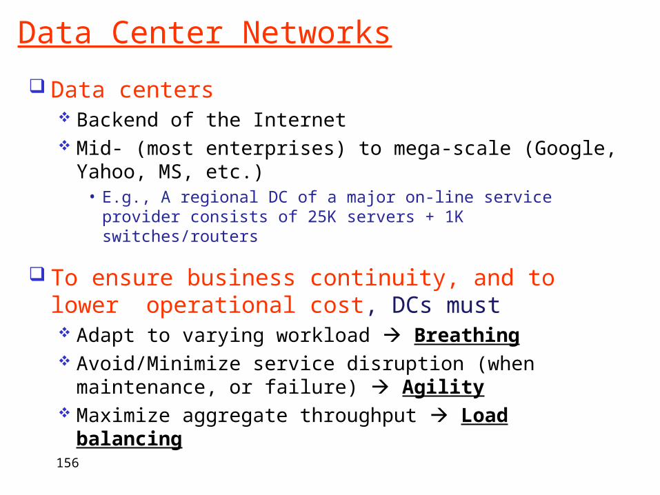
Data Center Networks
Data centers Backend of the Internet Mid- (most enterprises) to mega-scale (Google,
Yahoo, MS, etc.)• E.g., A regional DC of a major on-line service provider
consists of 25K servers + 1K switches/routers
To ensure business continuity, and to lower operational cost, DCs must Adapt to varying workload Breathing Avoid/Minimize service disruption (when
maintenance, or failure) Agility Maximize aggregate throughput Load
balancing156
Challenges posed by These Trends
Scalability: capability to connect tens of thousands, millions or more users and devices routing table size, constrained by router memory, lookup speed
Mobility: hosts are more mobile need to separate location (“addressing”) and identity (“naming”)
Availability & Reliability: must be resilient to failures need to be “proactive” instead of reactive need to localize effect of failures
Manageability: ease of deployment, “plug-&-play” need to minimize manual configuration self-configure, self-organize, while ensuring security and trust
…….
157
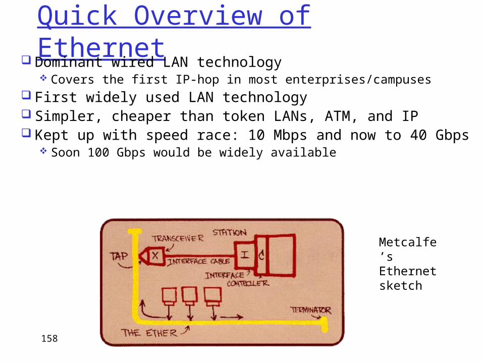
Quick Overview of Ethernet Dominant wired LAN technology
Covers the first IP-hop in most enterprises/campuses First widely used LAN technology Simpler, cheaper than token LANs, ATM, and IP Kept up with speed race: 10 Mbps and now to 40 Gbps
Soon 100 Gbps would be widely available
Metcalfe’s Ethernetsketch
158
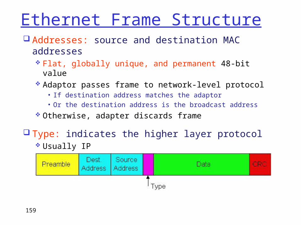
Ethernet Frame Structure Addresses: source and destination MAC
addresses Flat, globally unique, and permanent 48-bit
value Adaptor passes frame to network-level protocol
• If destination address matches the adaptor• Or the destination address is the broadcast address
Otherwise, adapter discards frame
Type: indicates the higher layer protocol Usually IP
159
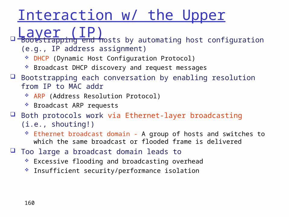
Interaction w/ the Upper Layer (IP) Bootstrapping end hosts by automating host configuration (e.g., IP
address assignment) DHCP (Dynamic Host Configuration Protocol) Broadcast DHCP discovery and request messages
Bootstrapping each conversation by enabling resolution from IP to MAC addr
ARP (Address Resolution Protocol) Broadcast ARP requests
Both protocols work via Ethernet-layer broadcasting (i.e., shouting!) Ethernet broadcast domain - A group of hosts and switches to which the
same broadcast or flooded frame is delivered Too large a broadcast domain leads to
Excessive flooding and broadcasting overhead Insufficient security/performance isolation
160
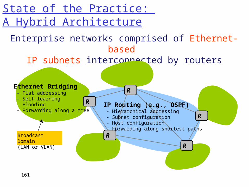
State of the Practice: A Hybrid Architecture
Enterprise networks comprised of Ethernet-based
IP subnets interconnected by routers
R
R
R
R
Ethernet Bridging - Flat addressing - Self-learning - Flooding - Forwarding along a tree
IP Routing (e.g., OSPF) - Hierarchical addressing - Subnet configuration - Host configuration - Forwarding along shortest paths
R
Broadcast Domain(LAN or VLAN)
161
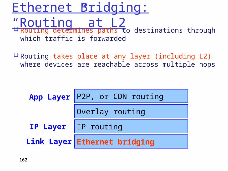
Ethernet Bridging: “Routing” at L2 Routing determines paths to destinations through
which traffic is forwarded
Routing takes place at any layer (including L2) where devices are reachable across multiple hops
IP routing
Overlay routing
P2P, or CDN routing
Ethernet bridging
IP Layer
App Layer
Link Layer
162
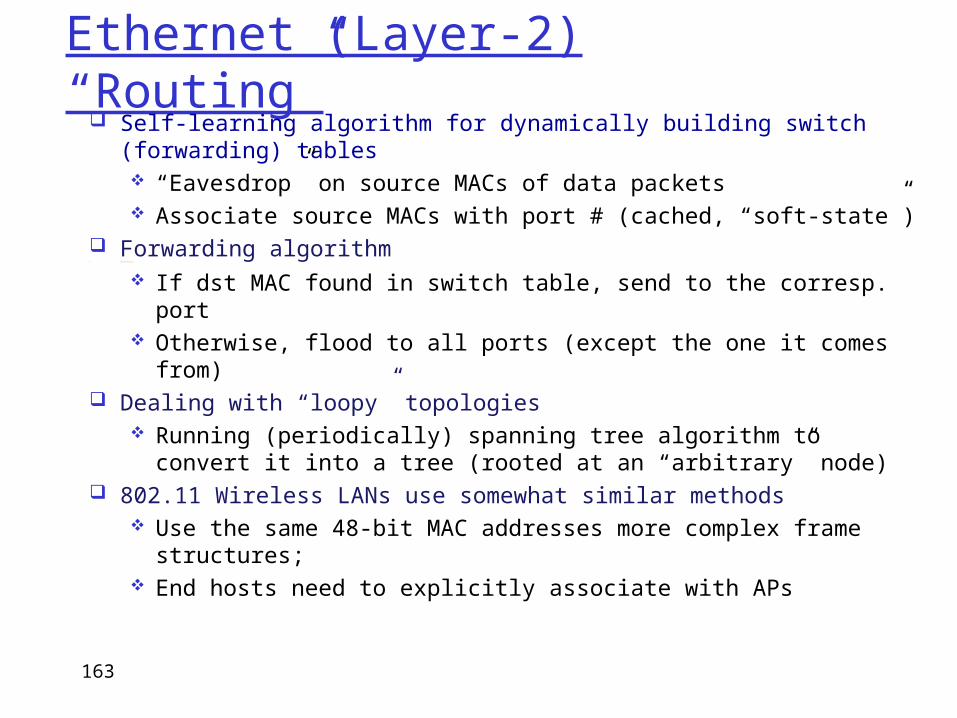
Ethernet (Layer-2) “Routing” Self-learning algorithm for dynamically building switch
(forwarding) tables “Eavesdrop” on source MACs of data packets Associate source MACs with port # (cached, “soft-state”)
Forwarding algorithm Forwarding algorithm
If dst MAC found in switch table, send to the corresp. port Otherwise, flood to all ports (except the one it comes
from) Dealing with “loopy” topologies
Running (periodically) spanning tree algorithm to convert it into a tree (rooted at an “arbitrary” node)
802.11 Wireless LANs use somewhat similar methods Use the same 48-bit MAC addresses more complex frame
structures; End hosts need to explicitly associate with APs
163
164
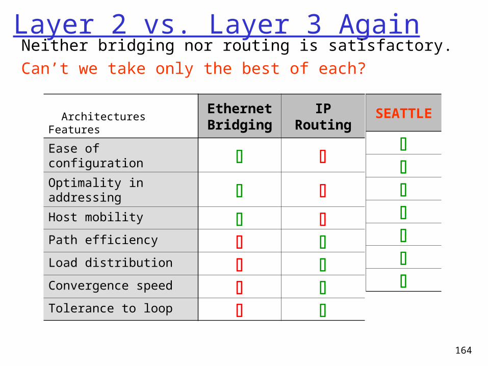
Layer 2 vs. Layer 3 AgainNeither bridging nor routing is satisfactory.Can’t we take only the best of each?
ArchitecturesFeatures
EthernetBridging
IPRouting
Ease of configuration Optimality in addressing Host mobility Path efficiency Load distribution Convergence speed Tolerance to loop
SEATTLE
SEATTLE (Scalable Ethernet ArchiTecTure for Larger Enterprises)
Plug-and-playable enterprise architecture ensuring both scalability and efficiency
Objectives Avoiding flooding Restraining broadcasting Keeping forwarding tables small Ensuring path efficiency
SEATTLE architecture – design principles Hash-based location management Shortest-path forwarding Responding to network dynamics (reactive location
resolution and caching) Lessons
Trading a little data-plane efficiency for huge control-plane scalability makes a qualitatively different system
165
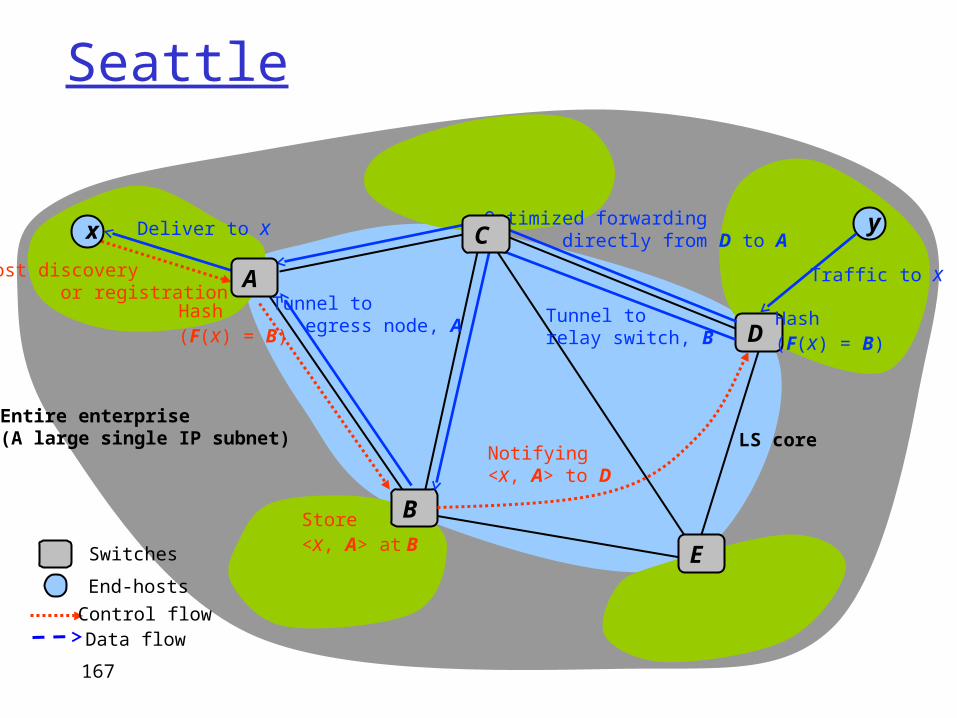
Seattle
Host discovery or registration
B
D
x y
Hash(F(x) = B)
Store<x, A> at B
Traffic to x
Hash(F(x) = B)
Tunnel to egress node, A
Deliver to x
Switches
End-hosts
Control flowData flow
Notifying<x, A> to D
Entire enterprise(A large single IP subnet) LS core
E
Optimized forwarding directly from D to AC
A
Tunnel to relay switch, B
167
168
Cloud Computing and Data Centers
Why Study this: they represent part of current and “future” trends
how applications will be serviced, delivered, … what are important “new” networking problems?
more importantly, what lessons can we learn in terms of (future) networking design? closely related, and there are many similar
issues/challenges (availability, reliability, scalability, manageability, ….)
(but of course, there are also unique challenges in networking)
169
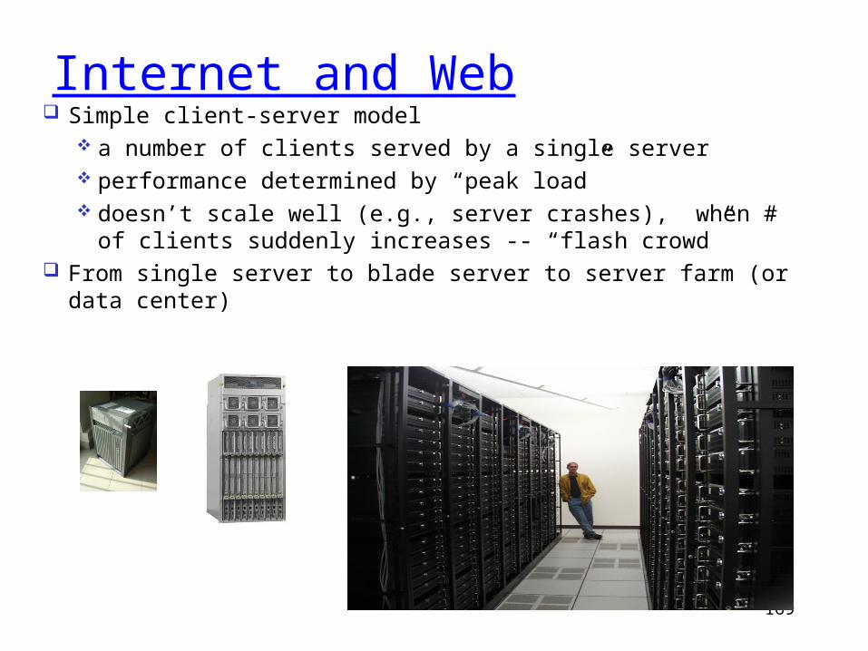
Internet and Web Simple client-server model
a number of clients served by a single server performance determined by “peak load” doesn’t scale well (e.g., server crashes), when # of clients
suddenly increases -- “flash crowd” From single server to blade server to server farm (or data
center)
170
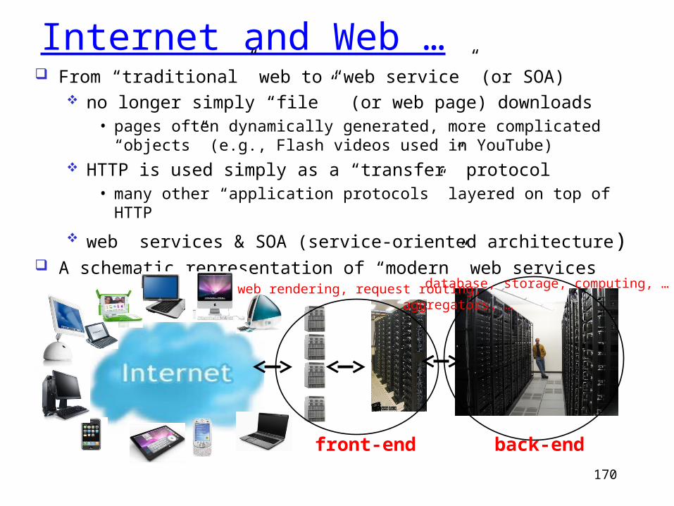
Internet and Web … From “traditional” web to “web service” (or SOA)
no longer simply “file” (or web page) downloads• pages often dynamically generated, more complicated
“objects” (e.g., Flash videos used in YouTube) HTTP is used simply as a “transfer” protocol
• many other “application protocols” layered on top of HTTP
web services & SOA (service-oriented architecture) A schematic representation of “modern” web services
front-end
web rendering, request routing, aggregators, …
back-end
database, storage, computing, …
171
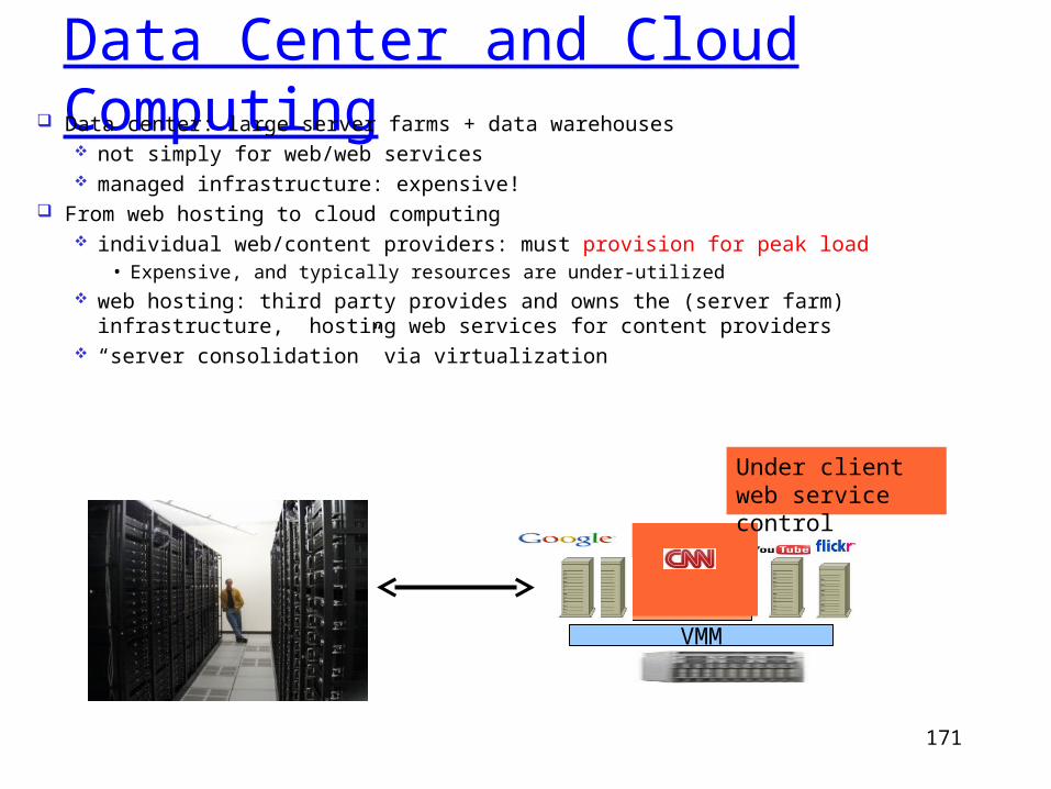
Data Center and Cloud Computing Data center: large server farms + data warehouses
not simply for web/web services managed infrastructure: expensive!
From web hosting to cloud computing individual web/content providers: must provision for peak load
• Expensive, and typically resources are under-utilized web hosting: third party provides and owns the (server farm) infrastructure,
hosting web services for content providers “server consolidation” via virtualization
VMMGuest OS
App
Under client web service control
172
Cloud Computing Cloud computing and cloud-based services:
beyond web-based “information access” or “information delivery” computing, storage, …
Cloud Computing: NIST Definition "Cloud computing is a model for enabling convenient, on-demand network access to a shared pool of configurable computing resources (e.g.,
networks, servers, storage, applications, and services) that can be rapidly provisioned and released with minimal management effort or service provider interaction."
Models of Cloud Computing “Infrastructure as a Service” (IaaS), e.g., Amazon EC2, Rackspace
“Platform as a Service” (PaaS), e.g., Micorsoft Azure
“Software as a Service” (SaaS), e.g., Google
173
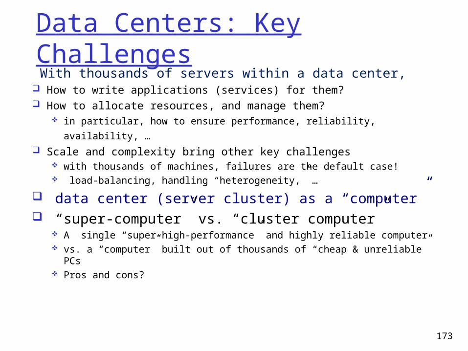
Data Centers: Key Challenges With thousands of servers within a data center, How to write applications (services) for them? How to allocate resources, and manage them?
in particular, how to ensure performance, reliability, availability, …
Scale and complexity bring other key challenges
with thousands of machines, failures are the default case! load-balancing, handling “heterogeneity,” …
data center (server cluster) as a “computer” “super-computer” vs. “cluster computer”
A single “super-high-performance” and highly reliable computer vs. a “computer” built out of thousands of “cheap & unreliable”
PCs Pros and cons?
Data Center NetworkingMajor Theme: What are new networking issues posed by large-
scale data centers? Network Architecture? Topology design? Addressing? Routing? Forwarding?
180 CSci5221: Data Center Networking, and Large-Scale Enterprise Networks: Part I
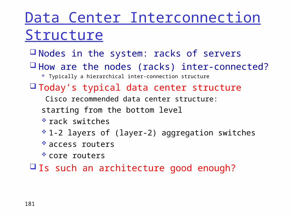
Data Center Interconnection Structure Nodes in the system: racks of servers How are the nodes (racks) inter-connected?
Typically a hierarchical inter-connection structure
Today’s typical data center structure Cisco recommended data center structure:
starting from the bottom level rack switches 1-2 layers of (layer-2) aggregation switches access routers core routers
Is such an architecture good enough?
181
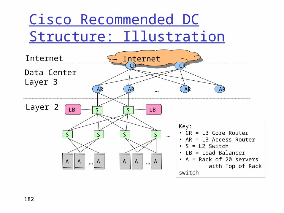
Cisco Recommended DC Structure: Illustration
182
InternetInternetCR CR
AR AR AR AR…
SSLB LB
Data CenterLayer 3
Internet
SS
A AA …
SS
A AA …
…
Layer 2
Key:• CR = L3 Core Router• AR = L3 Access Router• S = L2 Switch• LB = Load Balancer• A = Rack of 20 servers with Top of Rack switch
Data Center Design Requirements Data centers typically run two types of applications
outward facing (e.g., serving web pages to users) internal computations (e.g., MapReduce for web indexing)
Workloads often unpredictable: Multiple services run concurrently within a DC Demand for new services may spike unexpected
• Spike of demands for new services mean success!• But this is when success spells trouble (if not prepared)!
Failures of servers are the norm Recall that GFS, MapReduce, etc., resort to dynamic re-
assignment of chunkservers, jobs/tasks (worker servers) to deal with failures; data is often replicated across racks, …
“Traffic matrix” between servers are constantly changing
183
Data Center Costs Data centers typically run two types of applications
outward facing (e.g., serving web pages to users) internal computations (e.g., MapReduce for web indexing)
Workloads often unpredictable: Multiple services run concurrently within a DC Demand for new services may spike unexpected
• Spike of demands for new services mean success!• But this is when success spells trouble (if not prepared)!
Failures of servers are the norm Recall that GFS, MapReduce, etc., resort to dynamic re-
assignment of chunkservers, jobs/tasks (worker servers) to deal with failures; data is often replicated across racks, …
“Traffic matrix” between servers are constantly changing
184
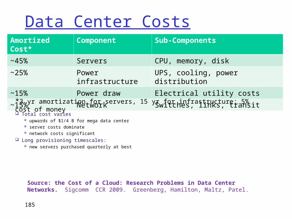
Data Center Costs
Total cost varies upwards of $1/4 B for mega data center server costs dominate network costs significant
Long provisioning timescales: new servers purchased quarterly at best
185
Amortized Cost*
Component Sub-Components
~45% Servers CPU, memory, disk
~25% Power infrastructure
UPS, cooling, power distribution
~15% Power draw Electrical utility costs
~15% Network Switches, links, transit*3 yr amortization for servers, 15 yr for infrastructure; 5% cost of money
Source: the Cost of a Cloud: Research Problems in Data Center Networks. Sigcomm CCR 2009. Greenberg, Hamilton, Maltz, Patel.
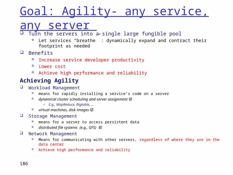
Goal: Agility- any service, any server Turn the servers into a single large fungible pool
Let services “breathe” : dynamically expand and contract their footprint as needed
Benefits Increase service developer productivity Lower cost Achieve high performance and reliability
Achieving Agility Workload Management
means for rapidly installing a service’s code on a server dynamical cluster scheduling and server assignment
• E.g., MapReduce, Bigtable, … virtual machines, disk images
Storage Management means for a server to access persistent data distributed file systems (e.g., GFS)
Network Management Means for communicating with other servers, regardless of where they are in the data center Achieve high performance and reliability
186
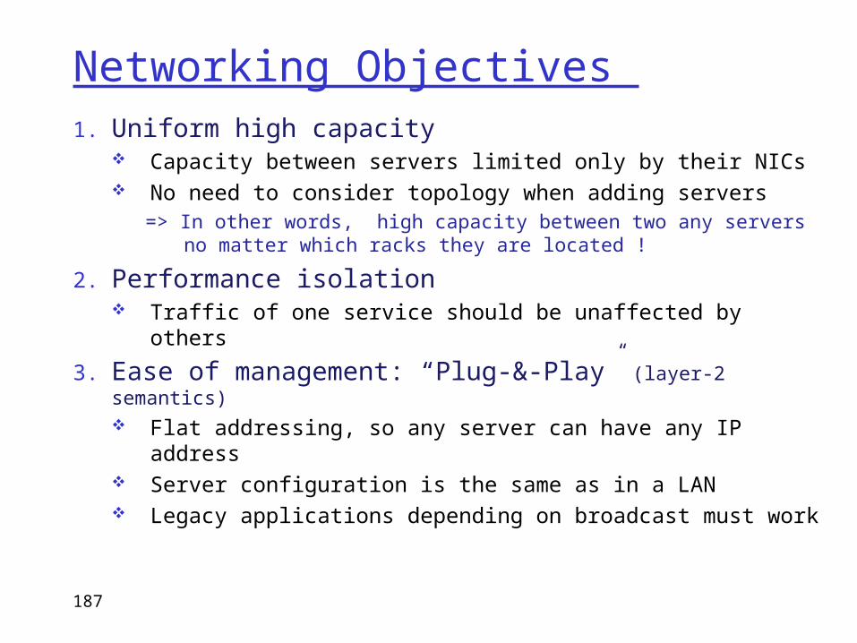
Networking Objectives 1. Uniform high capacity
Capacity between servers limited only by their NICs No need to consider topology when adding servers
=> In other words, high capacity between two any servers no matter which racks they are located !
2. Performance isolation Traffic of one service should be unaffected by others
3. Ease of management: “Plug-&-Play” (layer-2 semantics) Flat addressing, so any server can have any IP address Server configuration is the same as in a LAN Legacy applications depending on broadcast must
work
187
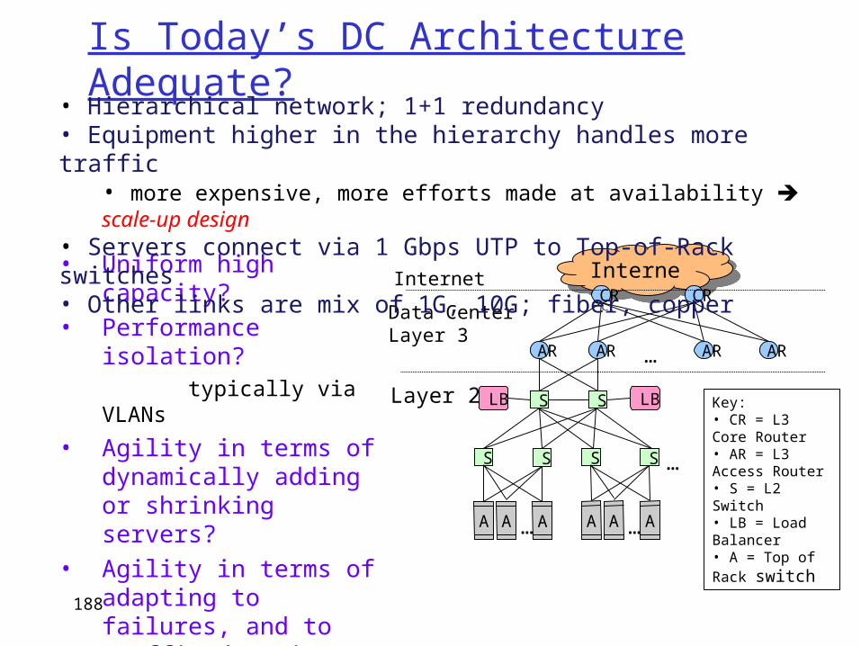
Is Today’s DC Architecture Adequate?
188
InternetInternetCR CR
AR AR AR AR…
SSLB LB
Data CenterLayer 3
Internet
SS
A AA …
SS
A AA …
…
Layer 2 Key:• CR = L3 Core Router• AR = L3 Access Router• S = L2 Switch• LB = Load Balancer• A = Top of Rack switch
• Uniform high capacity?• Performance isolation? typically via VLANs
• Agility in terms of dynamically adding or shrinking servers?
• Agility in terms of adapting to failures, and to traffic dynamics?
• Ease of management?
• Hierarchical network; 1+1 redundancy• Equipment higher in the hierarchy handles more traffic
• more expensive, more efforts made at availability scale-up design• Servers connect via 1 Gbps UTP to Top-of-Rack switches• Other links are mix of 1G, 10G; fiber, copper
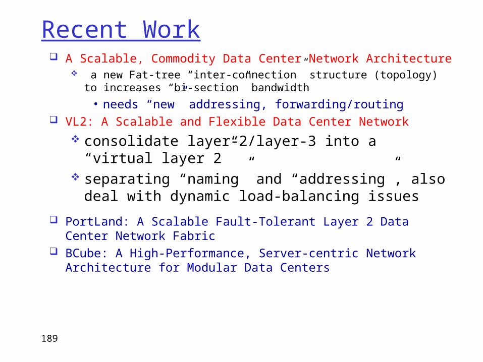
Recent Work A Scalable, Commodity Data Center Network Architecture
a new Fat-tree “inter-connection” structure (topology) to increases “bi-section” bandwidth
• needs “new” addressing, forwarding/routing VL2: A Scalable and Flexible Data Center Network
consolidate layer-2/layer-3 into a “virtual layer 2”
separating “naming” and “addressing”, also deal with dynamic load-balancing issues
PortLand: A Scalable Fault-Tolerant Layer 2 Data Center Network Fabric
BCube: A High-Performance, Server-centric Network Architecture for Modular Data Centers
189
A Scalable, Commodity Data Center Network Architecture Main Goal: addressing the limitations of today’s data
center network architecture single point of failure oversubscription of links higher up in the topology
• trade-offs between cost and providing
Key Design Considerations/Goals Allows host communication at line speed
• no matter where they are located! Backwards compatible with existing infrastructure
• no changes in application & support of layer 2 (Ethernet) Cost effective
• cheap infrastructure • and low power consumption & heat emission
190
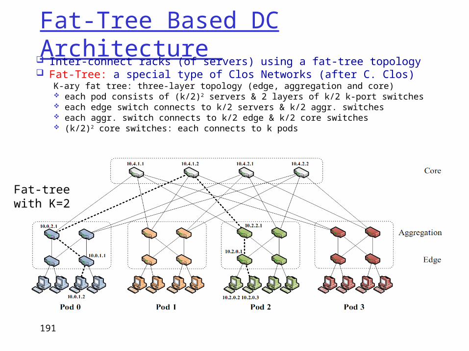
Fat-Tree Based DC Architecture Inter-connect racks (of servers) using a fat-tree topology Fat-Tree: a special type of Clos Networks (after C. Clos)
K-ary fat tree: three-layer topology (edge, aggregation and core) each pod consists of (k/2)2 servers & 2 layers of k/2 k-port switches each edge switch connects to k/2 servers & k/2 aggr. switches each aggr. switch connects to k/2 edge & k/2 core switches (k/2)2 core switches: each connects to k pods
Fat-tree with K=2
191
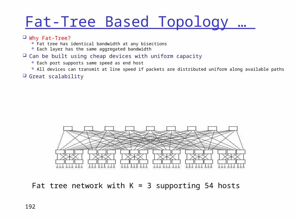
Fat-Tree Based Topology … Why Fat-Tree?
Fat tree has identical bandwidth at any bisections Each layer has the same aggregated bandwidth
Can be built using cheap devices with uniform capacity Each port supports same speed as end host All devices can transmit at line speed if packets are distributed uniform along available paths
Great scalability
Fat tree network with K = 3 supporting 54 hosts
192
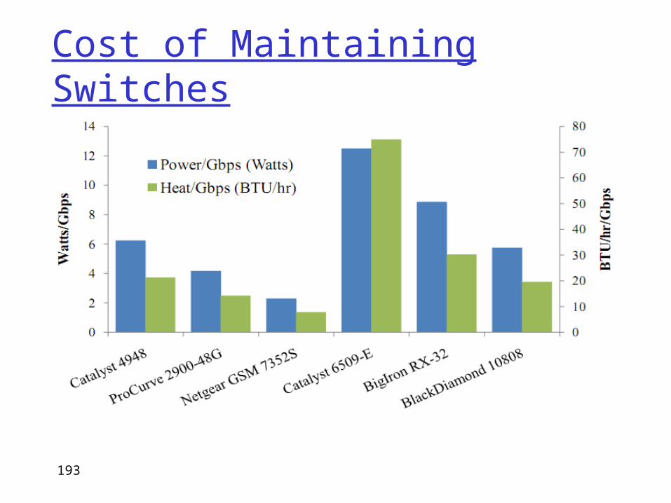
Cost of Maintaining Switches
193
Fat-tree Topology is Great, But …Does using fat-tree topology to inter-connect
racks of servers in itself sufficient? What routing protocols should we run on these
switches? Layer 2 switch algorithm: data plane flooding! Layer 3 IP routing:
shortest path IP routing will typically use only one path despite the path diversity in the topology
if using equal-cost multi-path routing at each switch independently and blindly, packet re-ordering may occur; further load may not necessarily be well-balanced
194
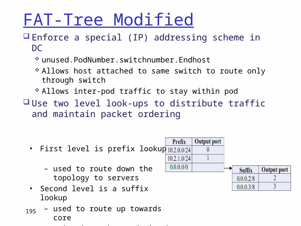
FAT-Tree Modified Enforce a special (IP) addressing scheme in DC
unused.PodNumber.switchnumber.Endhost Allows host attached to same switch to route only
through switch Allows inter-pod traffic to stay within pod
Use two level look-ups to distribute traffic and maintain packet ordering
• First level is prefix lookup– used to route down the
topology to servers• Second level is a suffix lookup
– used to route up towards core– maintain packet ordering by
using same ports for same server
195
More on Fat-Tree DC Architecture
Diffusion Optimizations Flow classification
Eliminates local congestion Assign to traffic to ports on a per-flow basis
instead of a per-host basis Flow scheduling
Eliminates global congestion Prevent long lived flows from sharing the
same links Assign long lived flows to different links
196

ADDITIONAL SLIDES
Introduction 1-197
Chapter 1: roadmap
1.1 What is the Internet?1.2 Network edge
end systems, access networks, links
1.3 Network core circuit switching, packet switching, network structure
1.4 Delay, loss and throughput in packet-switched networks
1.5 Protocol layers, service models1.6 Networks under attack: security1.7 History
Introduction 1-198
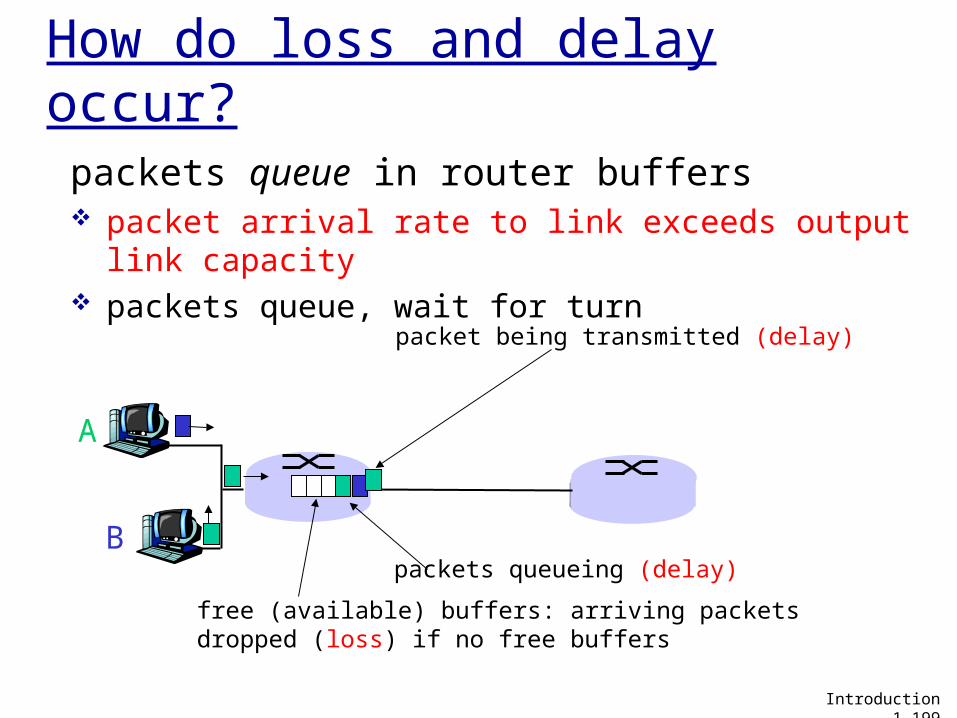
How do loss and delay occur?
packets queue in router buffers packet arrival rate to link exceeds output link
capacity packets queue, wait for turn
A
B
packet being transmitted (delay)
packets queueing (delay)
free (available) buffers: arriving packets dropped (loss) if no free buffers
Introduction 1-199
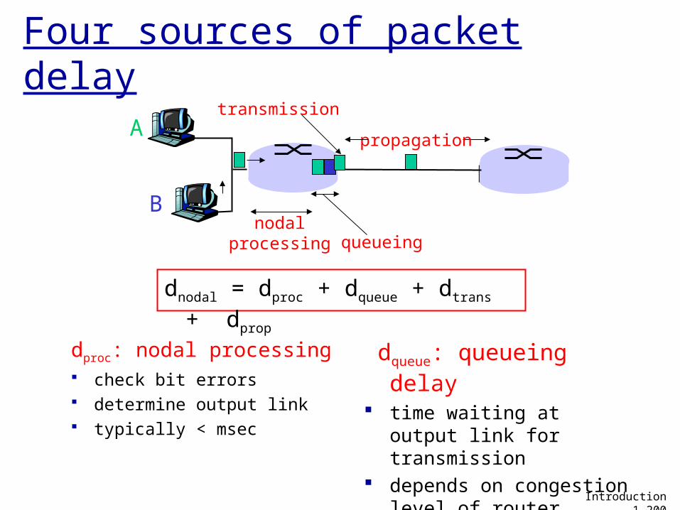
Four sources of packet delay
dproc: nodal processing check bit errors determine output link typically < msec
A
B
propagation
transmission
nodalprocessing queueing
dqueue: queueing delay time waiting at output
link for transmission depends on congestion
level of router
Introduction 1-200
dnodal = dproc + dqueue + dtrans + dprop
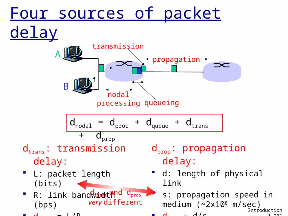
Four sources of packet delay
A
B
propagation
transmission
nodalprocessing queueing
Introduction 1-201
dnodal = dproc + dqueue + dtrans + dprop
dtrans: transmission delay:
L: packet length (bits) R: link bandwidth (bps) dtrans = L/R
dprop: propagation delay: d: length of physical link s: propagation speed in
medium (~2x10⁸ m/sec) dprop = d/sdtrans and dprop
very different
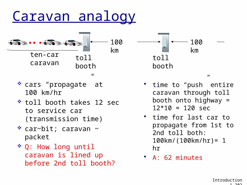
Caravan analogy
cars “propagate” at 100 km/hr
toll booth takes 12 sec to service car (transmission time)
car~bit; caravan ~ packet Q: How long until caravan
is lined up before 2nd toll booth?
time to “push” entire caravan through toll booth onto highway = 12*10 = 120 sec
time for last car to propagate from 1st to 2nd toll both: 100km/(100km/hr)= 1 hr
A: 62 minutes
toll booth
toll booth
ten-car caravan
100 km
100 km
Introduction 1-202
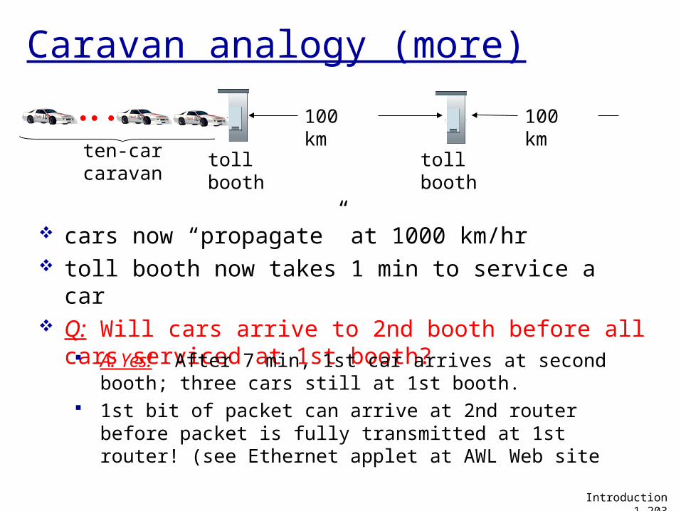
Caravan analogy (more)
cars now “propagate” at 1000 km/hr toll booth now takes 1 min to service a car Q: Will cars arrive to 2nd booth before all cars
serviced at 1st booth? A: Yes! After 7 min, 1st car arrives at second booth; three
cars still at 1st booth. 1st bit of packet can arrive at 2nd router before packet is
fully transmitted at 1st router! (see Ethernet applet at AWL Web site
toll booth
toll booth
ten-car caravan
100 km
100 km
Introduction 1-203
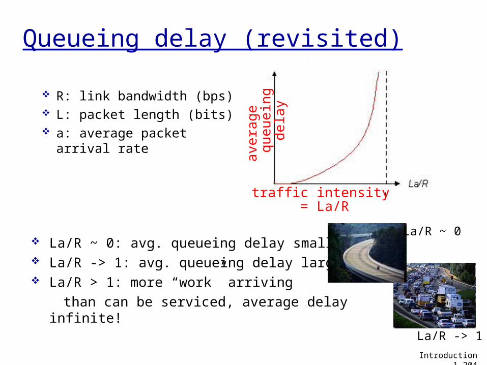
R: link bandwidth (bps) L: packet length (bits) a: average packet
arrival rate
traffic intensity = La/R
La/R ~ 0: avg. queueing delay small La/R -> 1: avg. queueing delay large La/R > 1: more “work” arriving than can be serviced, average delay infinite!
Introduction 1-204
avera
ge
qu
eu
ein
g
dela
y
La/R ~ 0
Queueing delay (revisited)
La/R -> 1
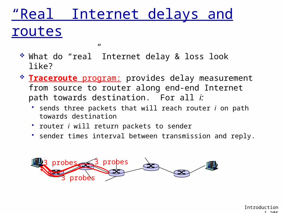
“Real” Internet delays and routes
What do “real” Internet delay & loss look like? Traceroute program: provides delay
measurement from source to router along end-end Internet path towards destination. For all i: sends three packets that will reach router i on path
towards destination router i will return packets to sender sender times interval between transmission and reply.
3 probes
3 probes
3 probes
Introduction 1-205
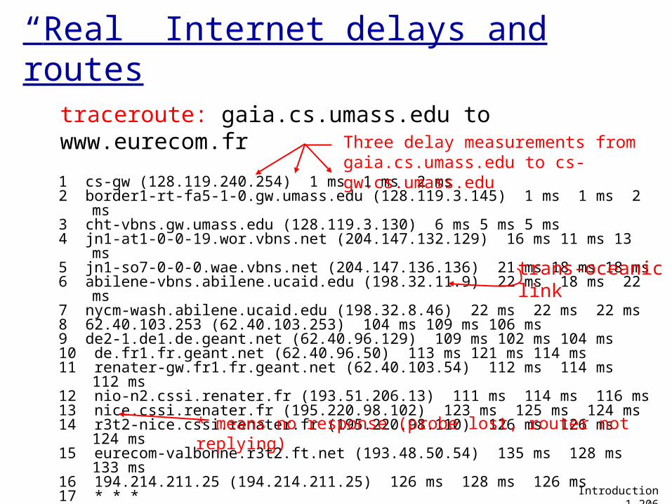
“Real” Internet delays and routes
1 cs-gw (128.119.240.254) 1 ms 1 ms 2 ms2 border1-rt-fa5-1-0.gw.umass.edu (128.119.3.145) 1 ms 1 ms 2 ms3 cht-vbns.gw.umass.edu (128.119.3.130) 6 ms 5 ms 5 ms4 jn1-at1-0-0-19.wor.vbns.net (204.147.132.129) 16 ms 11 ms 13 ms 5 jn1-so7-0-0-0.wae.vbns.net (204.147.136.136) 21 ms 18 ms 18 ms 6 abilene-vbns.abilene.ucaid.edu (198.32.11.9) 22 ms 18 ms 22 ms7 nycm-wash.abilene.ucaid.edu (198.32.8.46) 22 ms 22 ms 22 ms8 62.40.103.253 (62.40.103.253) 104 ms 109 ms 106 ms9 de2-1.de1.de.geant.net (62.40.96.129) 109 ms 102 ms 104 ms10 de.fr1.fr.geant.net (62.40.96.50) 113 ms 121 ms 114 ms11 renater-gw.fr1.fr.geant.net (62.40.103.54) 112 ms 114 ms 112 ms12 nio-n2.cssi.renater.fr (193.51.206.13) 111 ms 114 ms 116 ms13 nice.cssi.renater.fr (195.220.98.102) 123 ms 125 ms 124 ms14 r3t2-nice.cssi.renater.fr (195.220.98.110) 126 ms 126 ms 124 ms15 eurecom-valbonne.r3t2.ft.net (193.48.50.54) 135 ms 128 ms 133 ms16 194.214.211.25 (194.214.211.25) 126 ms 128 ms 126 ms17 * * *18 * * *19 fantasia.eurecom.fr (193.55.113.142) 132 ms 128 ms 136 ms
traceroute: gaia.cs.umass.edu to www.eurecom.frThree delay measurements from gaia.cs.umass.edu to cs-gw.cs.umass.edu
* means no response (probe lost, router not replying)
trans-oceaniclink
Introduction 1-206
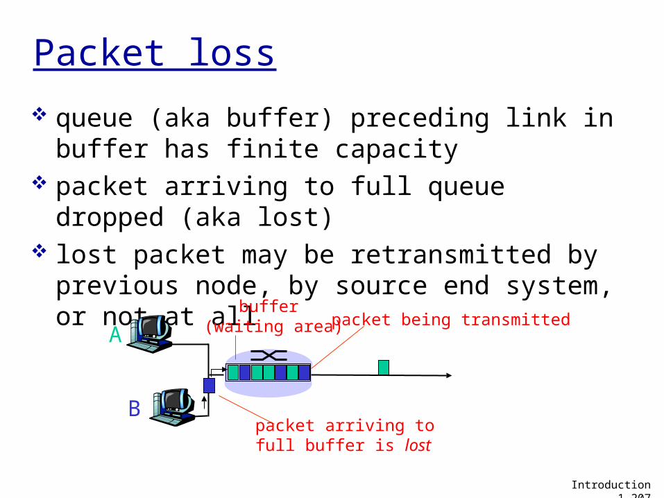
Packet loss
queue (aka buffer) preceding link in buffer has finite capacity
packet arriving to full queue dropped (aka lost)
lost packet may be retransmitted by previous node, by source end system, or not at all
A
B
packet being transmitted
packet arriving tofull buffer is lost
buffer (waiting area)
Introduction 1-207
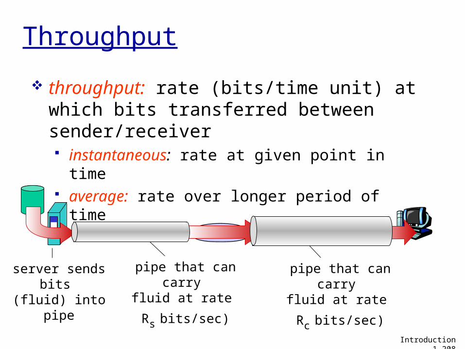
Throughput
throughput: rate (bits/time unit) at which bits transferred between sender/receiver instantaneous: rate at given point in time average: rate over longer period of time
server, withfile of F bits
to send to client
link capacity
Rs bits/sec
link capacity
Rc bits/secserver sends
bits (fluid) into pipe
Introduction 1-208
pipe that can carryfluid at rate
Rs bits/sec)
pipe that can carryfluid at rate
Rc bits/sec)
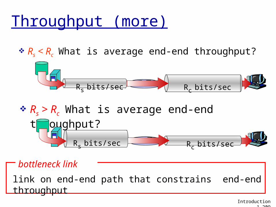
Throughput (more)
Rs < Rc What is average end-end throughput?
Rs bits/sec Rc bits/sec
Rs > Rc What is average end-end throughput?
Rs bits/sec Rc bits/sec
link on end-end path that constrains end-end throughput
bottleneck link
Introduction 1-209
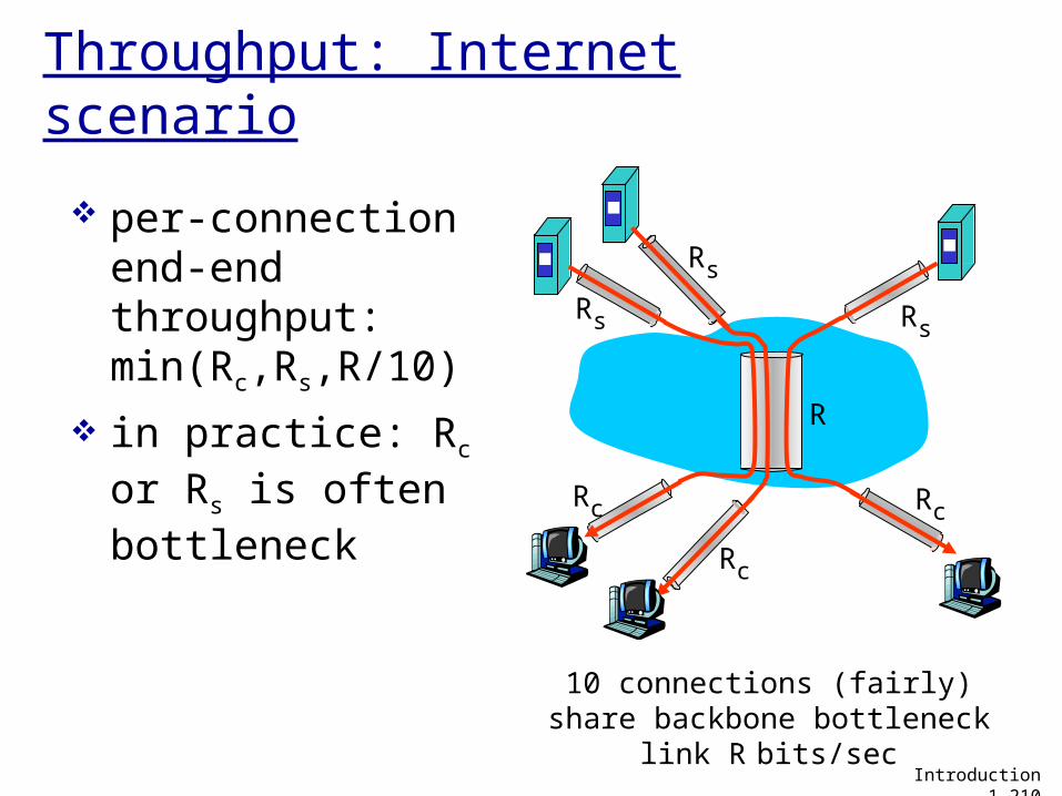
Throughput: Internet scenario
10 connections (fairly) share backbone bottleneck link R
bits/sec
Rs
Rs
Rs
Rc
Rc
Rc
R
per-connection end-end throughput: min(Rc,Rs,R/10)
in practice: Rc or Rs is often bottleneck
Introduction 1-210
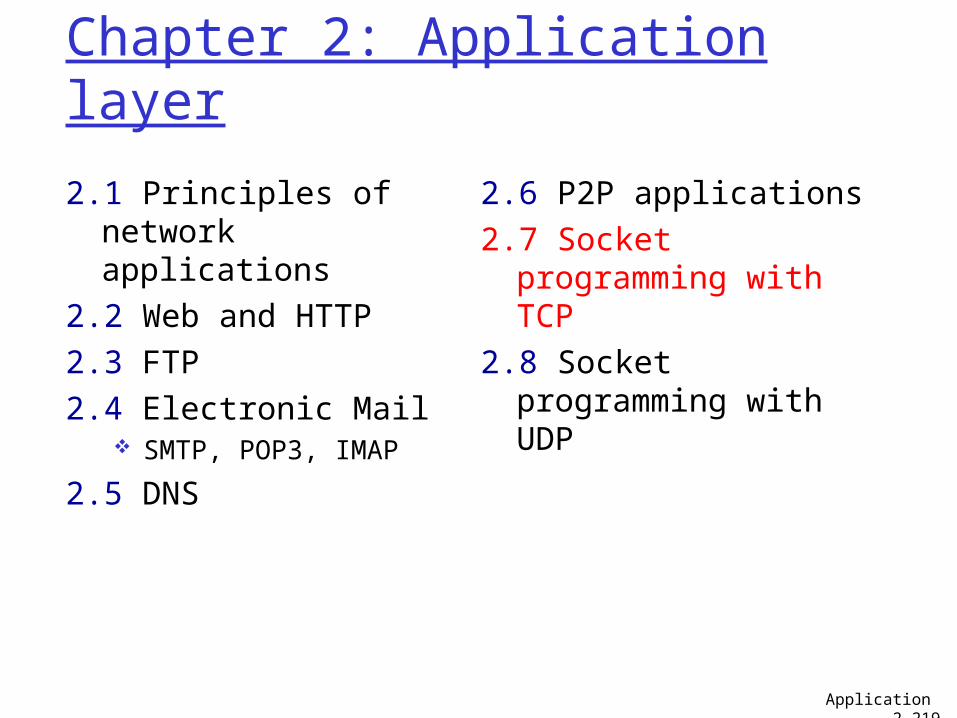
Chapter 2: Application layer
2.1 Principles of network applications
2.2 Web and HTTP2.3 FTP 2.4 Electronic Mail
SMTP, POP3, IMAP
2.5 DNS
2.6 P2P applications2.7 Socket programming
with TCP2.8 Socket programming
with UDP
Application 2-219
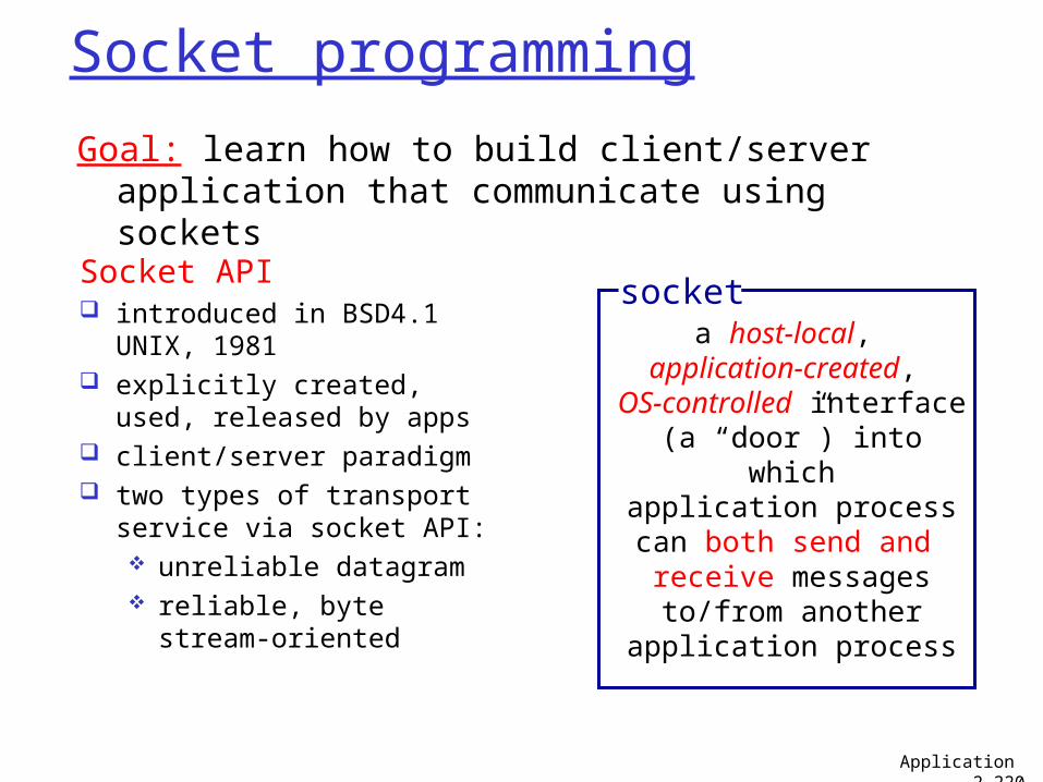
Socket programming
Socket API introduced in BSD4.1 UNIX,
1981 explicitly created, used,
released by apps client/server paradigm two types of transport
service via socket API: unreliable datagram reliable, byte stream-
oriented
a host-local, application-created,
OS-controlled interface (a “door”) into which
application process can both send and
receive messages to/from another
application process
socket
Goal: learn how to build client/server application that communicate using sockets
Application 2-220
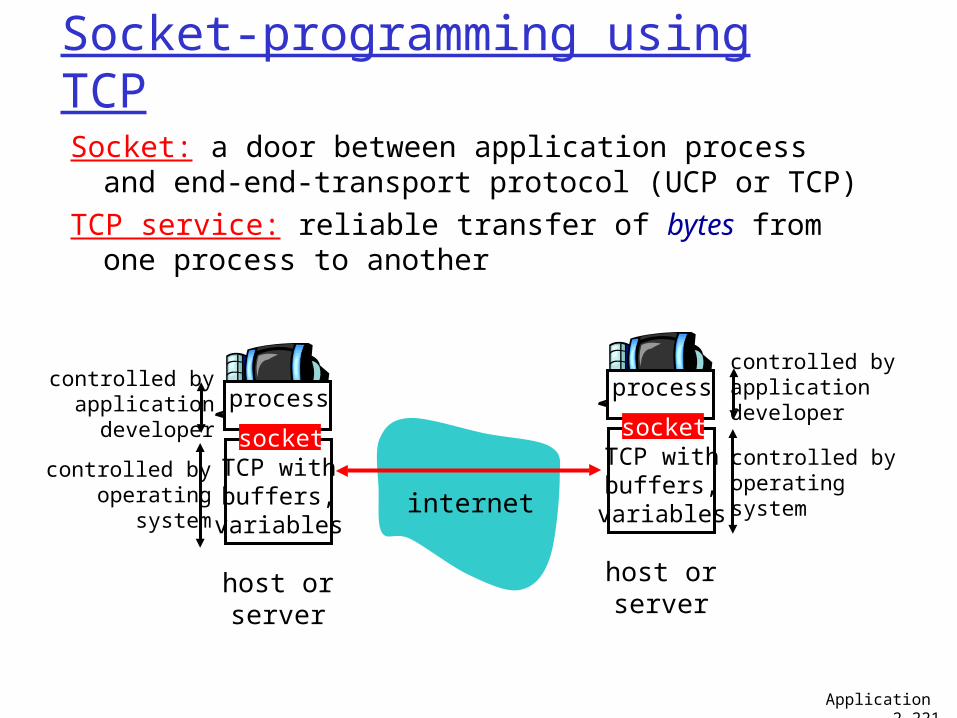
Socket-programming using TCP
Socket: a door between application process and end-end-transport protocol (UCP or TCP)
TCP service: reliable transfer of bytes from one process to another
process
TCP withbuffers,
variables
socket
controlled byapplicationdeveloper
controlled byoperating
system
host orserver
process
TCP withbuffers,
variables
socket
controlled byapplicationdeveloper
controlled byoperatingsystem
host orserver
internet
Application 2-221
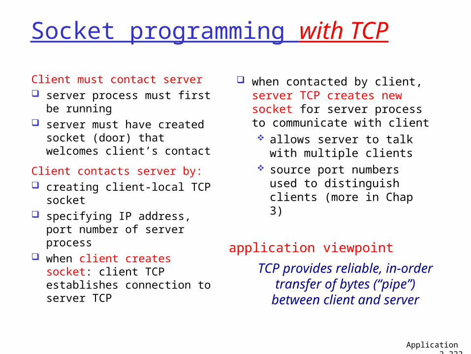
Socket programming with TCP
Client must contact server server process must first
be running server must have created
socket (door) that welcomes client’s contact
Client contacts server by: creating client-local TCP
socket specifying IP address, port
number of server process when client creates socket:
client TCP establishes connection to server TCP
when contacted by client, server TCP creates new socket for server process to communicate with client allows server to talk
with multiple clients source port numbers
used to distinguish clients (more in Chap 3)
TCP provides reliable, in-order transfer of bytes (“pipe”) between client and server
application viewpoint
Application 2-222
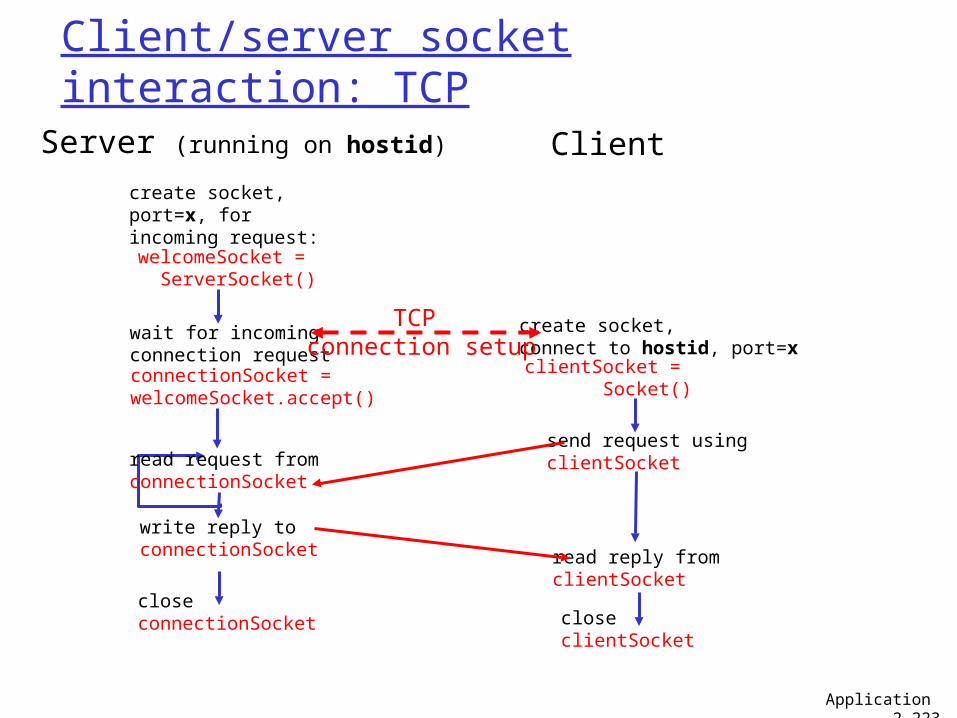
Client/server socket interaction: TCP
wait for incomingconnection requestconnectionSocket =welcomeSocket.accept()
create socket,port=x, forincoming request:welcomeSocket =
ServerSocket()
create socket,connect to hostid, port=xclientSocket =
Socket()
closeconnectionSocket
read reply fromclientSocket
closeclientSocket
Server (running on hostid) Client
send request usingclientSocketread request from
connectionSocket
write reply toconnectionSocket
TCP connection setup
Application 2-223
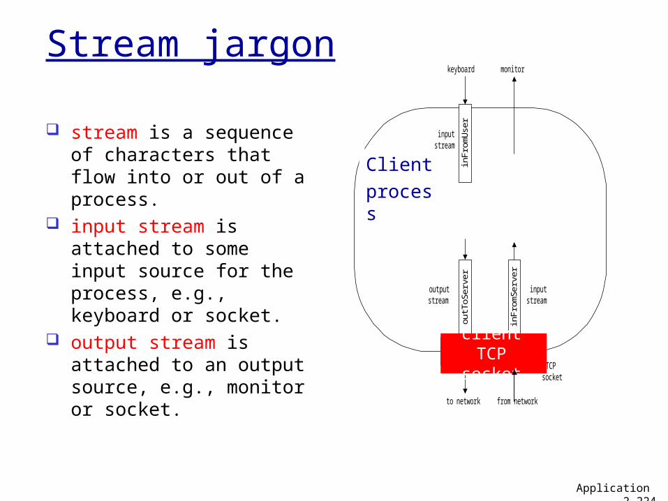
outT
oSer
ver
to network from network
inFr
omS
erve
r
inFr
omU
ser
keyboard monitor
Process
clientSocket
inputstream
inputstream
outputstream
TCPsocket
Client
process
client TCP socket
Stream jargon
stream is a sequence of characters that flow into or out of a process.
input stream is attached to some input source for the process, e.g., keyboard or socket.
output stream is attached to an output source, e.g., monitor or socket.
Application 2-224
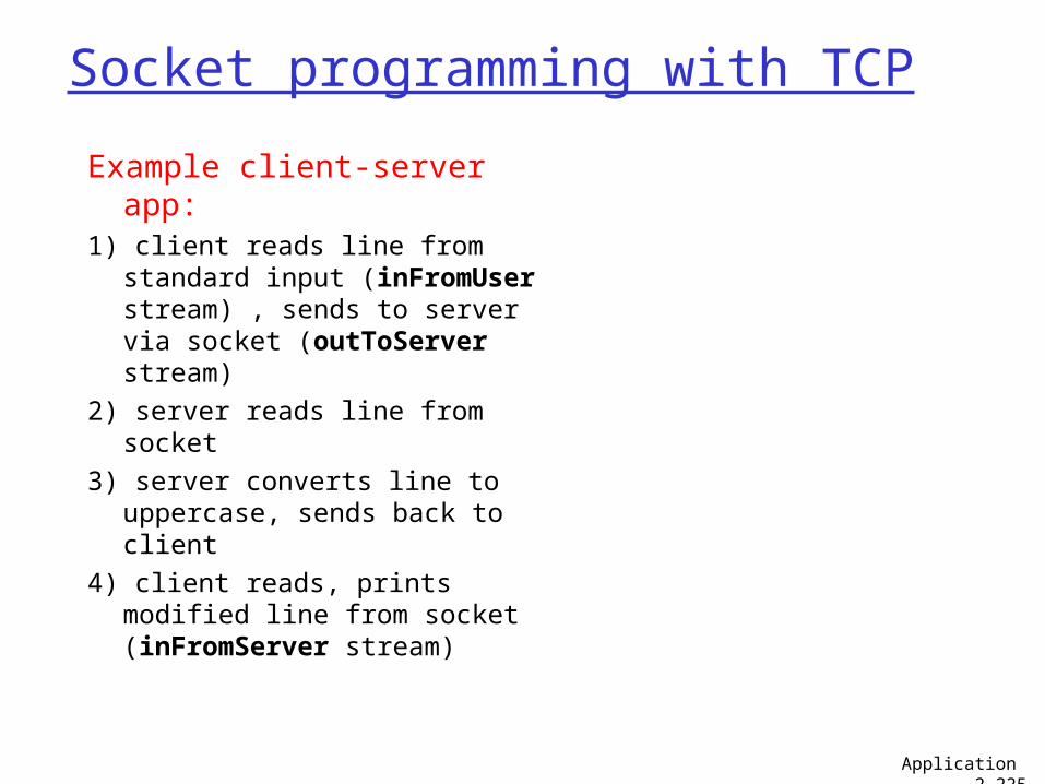
Socket programming with TCP
Example client-server app:
1) client reads line from standard input (inFromUser stream) , sends to server via socket (outToServer stream)
2) server reads line from socket3) server converts line to
uppercase, sends back to client
4) client reads, prints modified line from socket (inFromServer stream)
Application 2-225
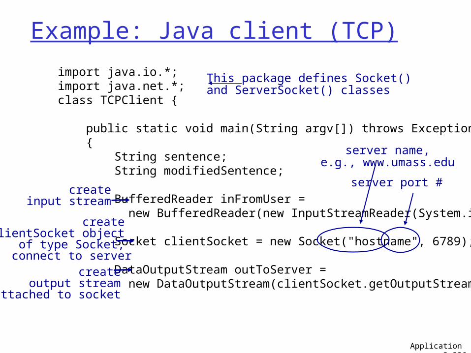
Example: Java client (TCP)
import java.io.*; import java.net.*; class TCPClient {
public static void main(String argv[]) throws Exception { String sentence; String modifiedSentence;
BufferedReader inFromUser = new BufferedReader(new InputStreamReader(System.in));
Socket clientSocket = new Socket("hostname", 6789);
DataOutputStream outToServer = new DataOutputStream(clientSocket.getOutputStream());
createinput stream
create clientSocket object
of type Socket, connect to server
createoutput stream
attached to socket
Application 2-226
This package defines Socket() and ServerSocket() classes
server port #
server name,e.g., www.umass.edu
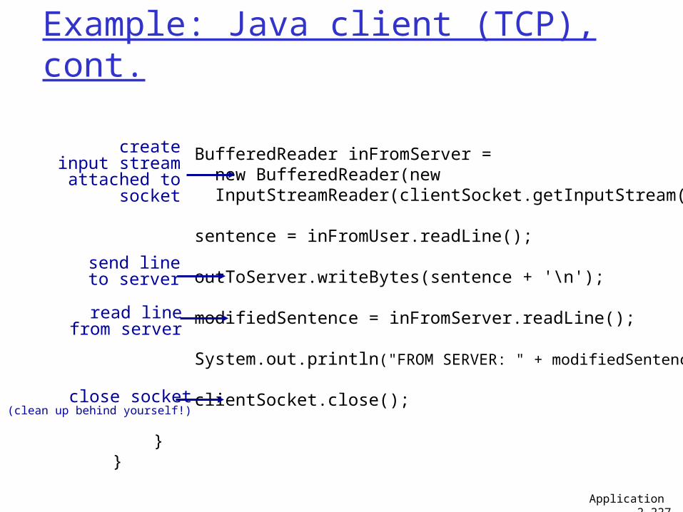
Example: Java client (TCP), cont.
BufferedReader inFromServer = new BufferedReader(new InputStreamReader(clientSocket.getInputStream()));
sentence = inFromUser.readLine();
outToServer.writeBytes(sentence + '\n');
modifiedSentence = inFromServer.readLine();
System.out.println("FROM SERVER: " + modifiedSentence);
clientSocket.close(); } }
createinput stream
attached to socket
send lineto server
read linefrom server
Application 2-227
close socket(clean up behind yourself!)
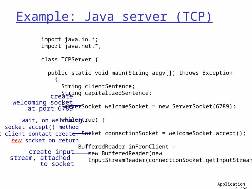
Example: Java server (TCP)
import java.io.*; import java.net.*;
class TCPServer {
public static void main(String argv[]) throws Exception { String clientSentence; String capitalizedSentence;
ServerSocket welcomeSocket = new ServerSocket(6789); while(true) { Socket connectionSocket = welcomeSocket.accept();
BufferedReader inFromClient = new BufferedReader(new InputStreamReader(connectionSocket.getInputStream()));
wait, on welcomingsocket accept() method
for client contact create, new socket on return
Application 2-228
createwelcoming socket
at port 6789
create inputstream, attached
to socket
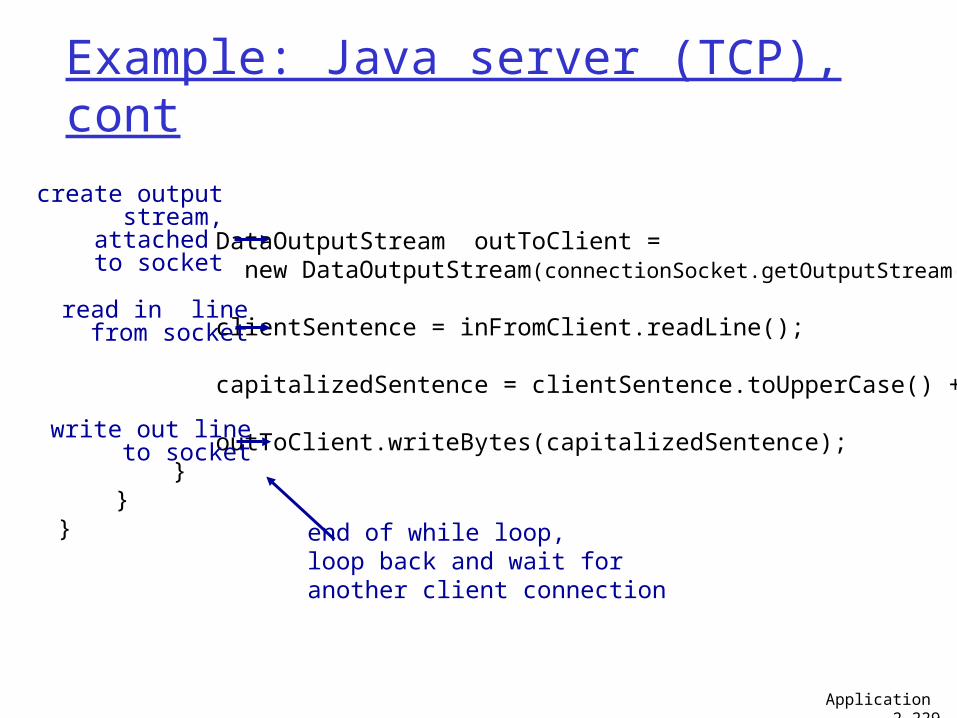
Example: Java server (TCP), cont
DataOutputStream outToClient = new DataOutputStream(connectionSocket.getOutputStream());
clientSentence = inFromClient.readLine();
capitalizedSentence = clientSentence.toUpperCase() + '\n';
outToClient.writeBytes(capitalizedSentence); } } }
read in linefrom socket
create outputstream,
attached to socket
write out lineto socket
end of while loop,loop back and wait foranother client connection
Application 2-229
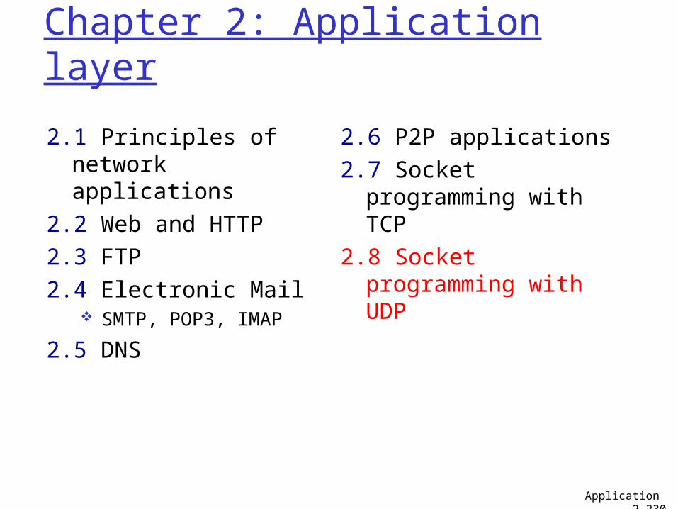
Chapter 2: Application layer
2.1 Principles of network applications
2.2 Web and HTTP2.3 FTP 2.4 Electronic Mail
SMTP, POP3, IMAP
2.5 DNS
2.6 P2P applications2.7 Socket programming
with TCP2.8 Socket programming
with UDP
Application 2-230
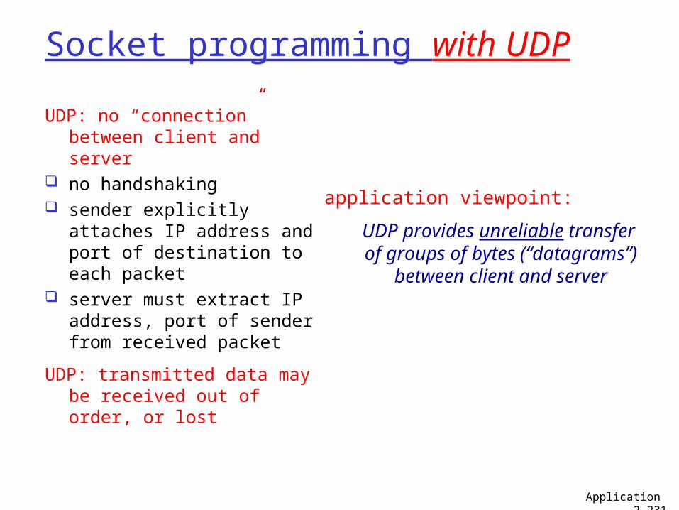
Socket programming with UDP
UDP: no “connection” between client and server
no handshaking sender explicitly attaches
IP address and port of destination to each packet
server must extract IP address, port of sender from received packet
UDP: transmitted data may be received out of order, or lost
application viewpoint:
UDP provides unreliable transfer of groups of bytes (“datagrams”)
between client and server
Application 2-231
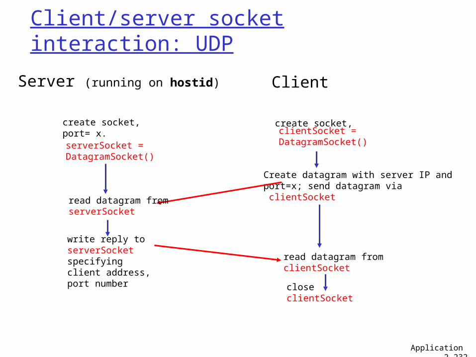
Client/server socket interaction: UDP
Server (running on hostid)
closeclientSocket
read datagram fromclientSocket
create socket,clientSocket = DatagramSocket()
Client
Create datagram with server IP andport=x; send datagram via clientSocket
create socket,port= x.serverSocket = DatagramSocket()
read datagram fromserverSocket
write reply toserverSocketspecifying client address,port number
Application 2-232
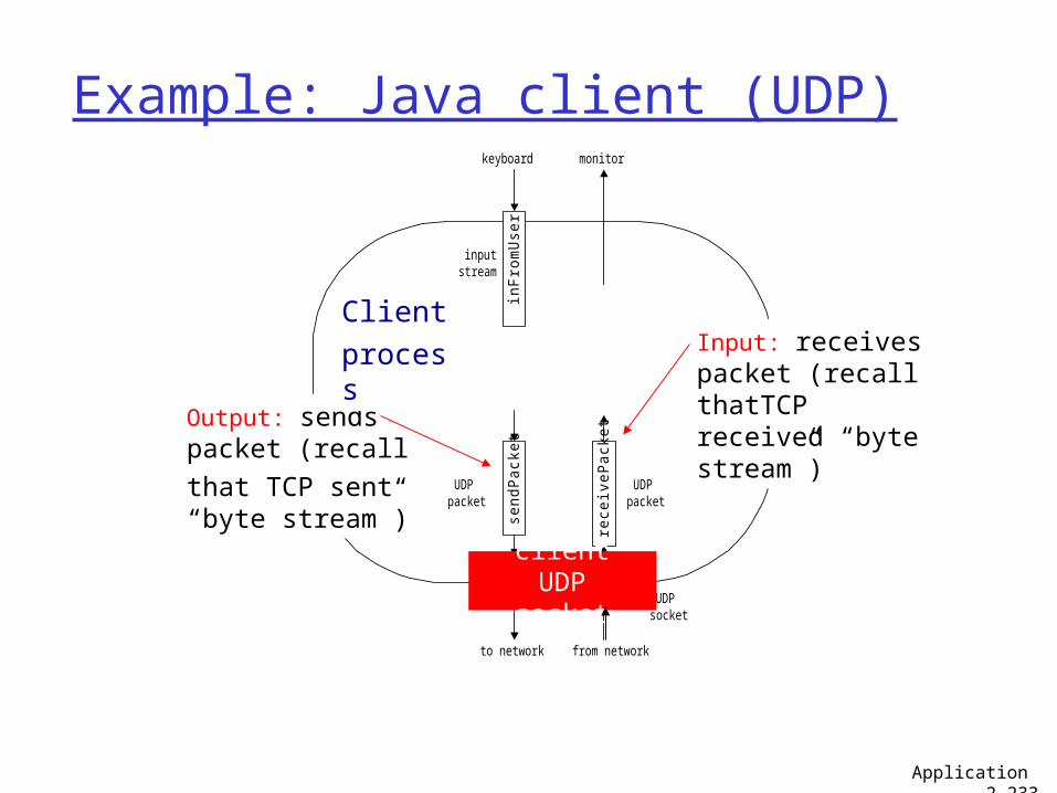
Example: Java client (UDP)
sendP
ack
et
to network from network
rece
iveP
ack
et
inF
rom
Use
r
keyboard monitor
Process
clientSocket
UDPpacket
inputstream
UDPpacket
UDPsocket
Output: sends packet (recall
that TCP sent “byte stream”)
Input: receives packet (recall thatTCP received “byte stream”)
Client
process
client UDP socket
Application 2-233
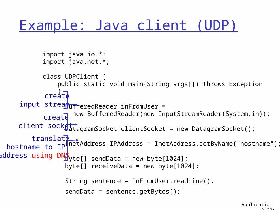
Example: Java client (UDP)
import java.io.*; import java.net.*; class UDPClient { public static void main(String args[]) throws Exception { BufferedReader inFromUser = new BufferedReader(new InputStreamReader(System.in)); DatagramSocket clientSocket = new DatagramSocket(); InetAddress IPAddress = InetAddress.getByName("hostname"); byte[] sendData = new byte[1024]; byte[] receiveData = new byte[1024]; String sentence = inFromUser.readLine();
sendData = sentence.getBytes();
createinput stream
create client socket
translate hostname to IP
address using DNS
Application 2-234
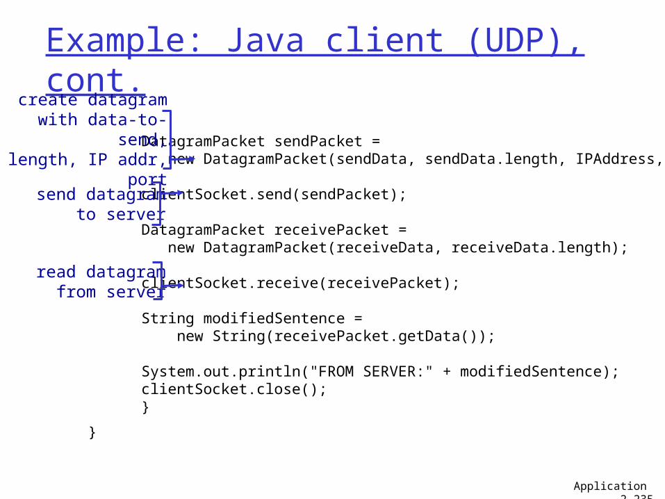
Example: Java client (UDP), cont.
DatagramPacket sendPacket = new DatagramPacket(sendData, sendData.length, IPAddress, 9876); clientSocket.send(sendPacket); DatagramPacket receivePacket = new DatagramPacket(receiveData, receiveData.length); clientSocket.receive(receivePacket); String modifiedSentence = new String(receivePacket.getData()); System.out.println("FROM SERVER:" + modifiedSentence); clientSocket.close(); }
}
create datagram with data-to-send,
length, IP addr, port
send datagramto server
read datagramfrom server
Application 2-235
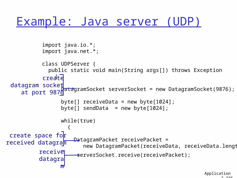
Example: Java server (UDP)
import java.io.*; import java.net.*; class UDPServer { public static void main(String args[]) throws Exception { DatagramSocket serverSocket = new DatagramSocket(9876); byte[] receiveData = new byte[1024]; byte[] sendData = new byte[1024]; while(true) { DatagramPacket receivePacket = new DatagramPacket(receiveData, receiveData.length);
serverSocket.receive(receivePacket);
createdatagram socket
at port 9876
create space forreceived datagram
receivedatagra
mApplication 2-236
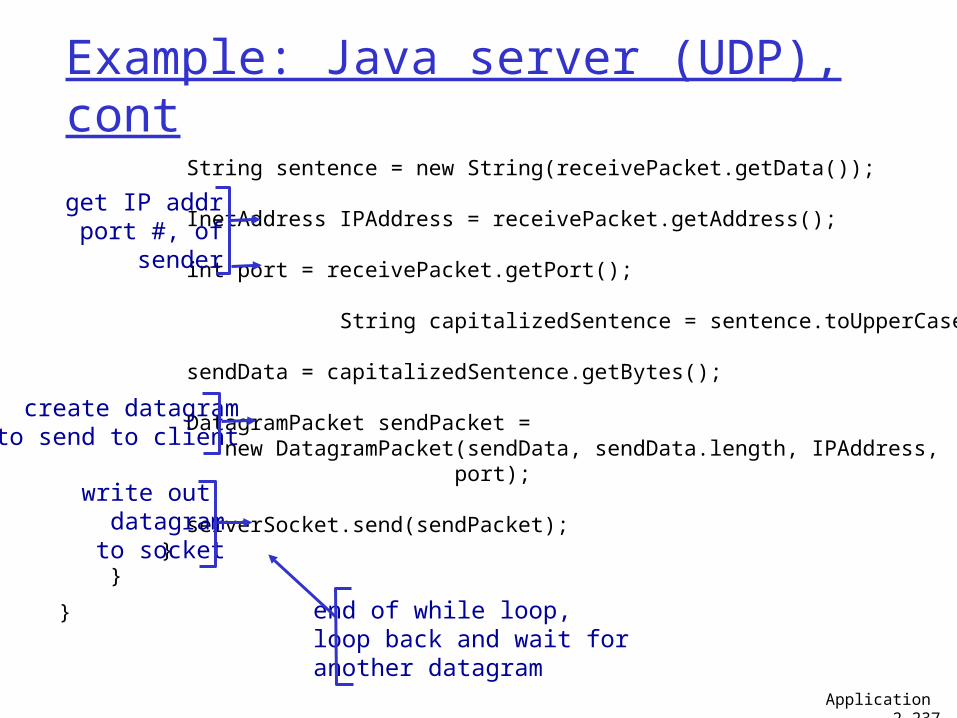
Example: Java server (UDP), cont
String sentence = new String(receivePacket.getData()); InetAddress IPAddress = receivePacket.getAddress(); int port = receivePacket.getPort(); String capitalizedSentence = sentence.toUpperCase();
sendData = capitalizedSentence.getBytes(); DatagramPacket sendPacket = new DatagramPacket(sendData, sendData.length, IPAddress, port); serverSocket.send(sendPacket); } }
}
get IP addrport #, of
sender
write out datagramto socket
end of while loop,loop back and wait foranother datagram
create datagramto send to client
Application 2-237
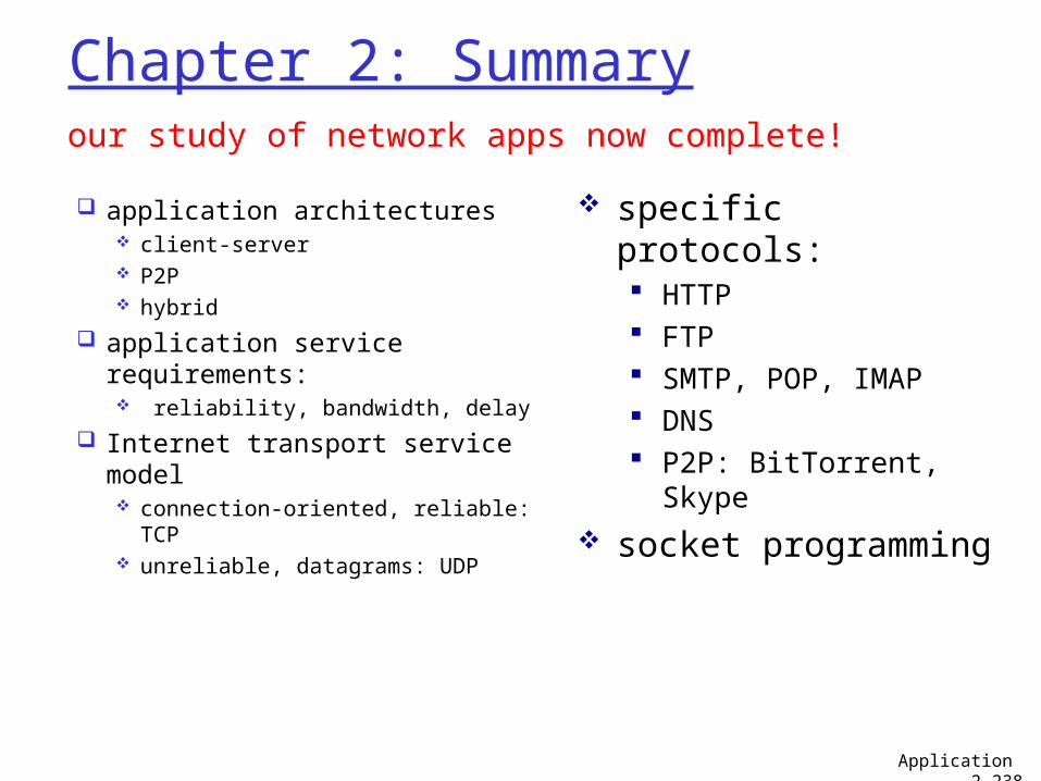
Chapter 2: Summary
application architectures client-server P2P hybrid
application service requirements: reliability, bandwidth, delay
Internet transport service model connection-oriented, reliable:
TCP unreliable, datagrams: UDP
our study of network apps now complete!
specific protocols: HTTP FTP SMTP, POP, IMAP DNS P2P: BitTorrent, Skype
socket programming
Application 2-238
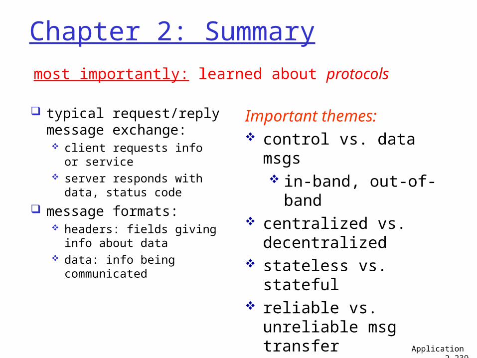
Chapter 2: Summary
typical request/reply message exchange: client requests info or
service server responds with
data, status code
message formats: headers: fields giving
info about data data: info being
communicated
most importantly: learned about protocols
Important themes: control vs. data msgs
in-band, out-of-band
centralized vs. decentralized
stateless vs. stateful reliable vs. unreliable
msg transfer “complexity at
network edge”Application 2-239


![Lecture 12: Fast Reinforcement Learning [1]With …web.stanford.edu/class/cs234/slides/lecture12_postclass.pdfLecture 12: Fast Reinforcement Learning 1 Emma Brunskill CS234 Reinforcement](https://img.pdfslide.us/doc/110x75/5ea9dceb336dde7b5c510cf2/lecture-12-fast-reinforcement-learning-1with-web-lecture-12-fast-reinforcement.jpg)
![Lecture 10: Policy Gradient III & Midterm Review =1[1]With ... › class › cs234 › slides › lecture10_1.pdf · Emma Brunskill (CS234 Reinforcement Learning. )Lecture 10: Policy](https://img.pdfslide.us/doc/110x75/5f24d18c0a096d071454a4b9/lecture-10-policy-gradient-iii-midterm-review-11with-a-class-a.jpg)


![Cementum in Disease[Nalini]](https://img.pdfslide.us/doc/110x75/55cf9d52550346d033ad2077/cementum-in-diseasenalini.jpg)